86215.pdf - federal highway administration
TRANSCRIPT

f>w RABLROADmMIIGHWAlf
U S DepaflmentofTransportation GRikDE CROSSING
F&era! ~IghwayAdmlnlWr*!on
HAIMDBOOK
–SEC4DND EDITION FHWA-TS-86”275SEPTEMBER1986
FOREWORO
This handbook provides general infer.nationon railroad-highway crossings,including Cilaracteristicsof the crossing environl~~nta~~ US~rs, and thephysical and operational improveinentsfor safe and efficient use by bothhighway and rail traffic. The handbook wil1 be of interest to Federal, Stateand local ilighwayagency personnel, railroad officials, consulting engineersand educators involved witilrailroad–highway grade crossi:lgsafety andoper3ti9n.
The late William J. Hedley contributed generously of his 5ackground andexperience tu,wardthe colnpletionof this handbook.
This is the second printing of the second edition of the handbook. The onlychange from the first pri,ltingis a revision of Figure 24, page 103, to reflectthe guidance for placement of the railroad crossing pavements marking synbol inrelation tu the location ,ofthe advance wa,-rringsign.
A standard distribution of the handbook was made to the FHdA Region andDivision offices, the State highway agencies and the T~ Centers in ?986.Copies of the handbook were also pr>vided to the Federal RailroadAd~:)inistrationand the Association of A;nericanRailroads for“their ~se. Alimited n(~mberof copies are available from the Railroads, IJtilitiesandPrograms Branch, HNG-?2, Federal liigl~wayAdministration, Washington, D.C. 205%and the RD&T Report Center, HRD-11, Federal Highway Administration, 6300Georgetown Pike, ~~cLean,Virginia 22101-23Y6. Copies maythe N~tional Technical Infer.lationService, 5285 Port RoyalVirginia 22161.
be pur~tlasedfroinRoad, Springfield,
.&&f s~~Stanley R. 3y(ngtonDirector, Office of ImplementationFederd? IiighwayAdministration
NOTICE
This document is disseminated under the sponsorship of the Department ofTrans})ortationin the interest [jfinformation exchange. The United StatesGovern!nentassumes no 1iai)i1ity for its contents or use thereof. The contentsof this report reflect the views of the author, who is responsible for theaccuracy of the data presented herein. The contents do not necessarilyreflect the official policy of the Departinentof Transportation].This reportdoes not constitute a standard, specification, or regulation.
“TheUnited States Govern;nentdoes not endorse products or manufacturers. Tradeor manufacturers’ names appear herein only because they are consideredessential to the object of tilisdoc(~ment.
T(@chnicolkepotiDocumentationpeg,
1. R.P.t, No.
FHWA TS-86-215
4.1;,1.andS.b+itl. ~2G0”*’”m*”’Ace*’s’O”M” ~=
Se?tember 1986Railroad-Highway Grade Crossing Handbook-2nd Edition ~,~.,,Q,m,n*~,gen,,o,,on~odo —
2- —8 P.r{o,m,.s O,g.n,,.,i.nR.p.,, N..7.A.?ho,,,)B.H. Tustin, H. Richards, H. i!cG(:e,and R. Patterson
9. P.,l.,mi.o0,9m,,.,;onNom.md Add,.,,—
/10.W..ku.,tN..(TRAISI
Tustin Enterprises2903 Maple Lane
FCP Category 12 (A)11.Con,,..,o,G,..,N..
—
Fairfax; Virginia 22031
c
13.Typ..1R.per,andP.r,.dCev.r.d12,S9..,.,;.$A9...YNom.o.dAdd,.,,
Office of ImplementationFederal Highway Administration6300 Georg;to~ Pike
r— -14.Sp..,.,,.g Ag..cyCod.
McLean, Virginia 22101-2296,
15.$.ppl.m.n,o,yN.,.,—
FHWA Contract Manager (COTR): Eric ltinley(HRT-20)FHWA Office of Engineering Cont:~ct: Jim Overton (KNG-12]FRA Office of Safety Analysis: Tom P. Well [RRS-Z:[)
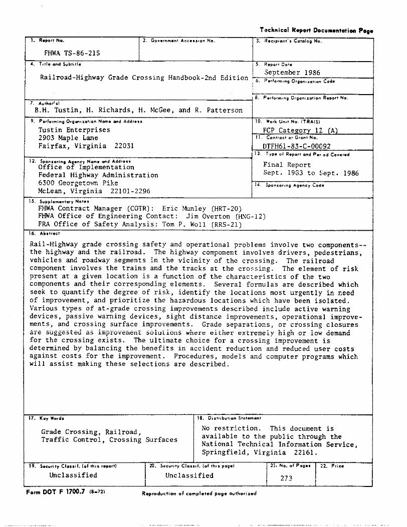
Rail-Highway grade crossing safety and operational problems involve two component$--the highway and the railroad. The!highway component involves drivers, pedestrians,vehicles and roadway segments in the vicinity of the crossing. The railroadcomponent involves the trains and the tracks at the crossing. The element of riskpresent at a given location is a function of the ch~lracteristicsof the twocomponents and their corresponding;elements. Sever:llformulas are described whichseek to quantify the degree of risk, identify the locations most urgently in needof improvement, and prioritize the!hazardous locations which have been isolated.Various types of at-grade crossin~;improvements described include active warningdevices, passive warning devices, sight distance improvements, operational improve-ments, and crossing surface improvements. Grade sel)arations,or crossing closuresare suggested as improvement solutions where either extremely high or low demmdfor the crossing exists. The ultimate choice for a crossing improvement isdetermined by balancing the benefits in accident reduction and reduced user costsagainst costs for the improvement. Procedures, models and computer programs whick~will assist making these selectior~sare described.
17.K,YWo,d, 18.Distrtb.?oon$?.~.m.nl—
Grade Crossing, Railroad,No restriction. This document is
Traffic Control, Crossing Surfaces availablt!to the public through theNational Technical Information Service,Springfield, Virginia 22161.
19,$.e.rityClo.sil.(.Ithisr.p.rt)
I ‘~z’ ““* -
m. S,,.vr; ty Clo,,, t. (ef,h,,pag.)
~classified Unclassified1 t i
:ormDOT F 17N.7 (6-72]—
R.p,od..?ionof..mpl.?edpg. ..lho,i=ed
I
GZ
22
12IOZ61
81
,1
,1
S1
bl
El
Z1
11
0T68L,
s,
s,
,~,
1111111111111111111I
IIlll’1!’11II
III
11111111111111111111
11111111111111111111
11111111111111111111
11111111111111111111
11111111
11111111
11111111
111111111111111111111
!111
11111111111111111
11111111
11111111
11!1
111111111111
11111111
,,,!,O!s!!,,!,,!,$!,!,,!,,,,,,,,,,,,,,,,,,,,,,,,,,,,,,,, ,,,,,,,,,,,,,,,,
IllIllIllIllIllIllIllIll1]1IllIllIllIll1]1IllIllIll1[1
98
32
1‘..,.,
17
16
Is
14
RAILROAD-llIG~AY GRADE CROSSING WNDBOOK
Chapter Pa{;e
List of Figures ............................. ..........................List of Tables ..........................................................
A. Backgromd ..........................................................1. Introduction to Railro/id-HighwayGrade Crossings .................2. Safety and Operations :itRailroad-Highw%y Grade Crossings ........
B. Railroad-Highway Grade Cr~>ssingPrograms ...........................C. Responsibilities at Railroad-Highway Grade Crossings ................D. Some General Lagal Considerations - Railroad-Highway Grade
Crossings .......................................)..................E. References ............................................................
II. COWONENTS OF A RAILROAD-HIG~AY GRADE CROSSING
A. The Highway Component ................................................1. Driver .............................................................2. Vehicle ...........................................................3. Roadway .....................................................<......4. Pedestrian ..................................................t.....
B. Railroad Components .................................................1. Train ...........................................................2. Track .............................................................
C. References ............................................................
III. ASSESS~NT OF CROSSING SAFETY AND OPERATION
A. Collection and Maintenance of Data ...................................B. Identification of CrOssinigsfor Further Analysis .................... .
1. Peabody Dimmick Formula ..........................................2. New Hampshire Index ...............................................3. NCHRP 50 ..........................................................4. U.S. DOT Accident Pred,ction~uations ...........................5. Florida DOT Accident Prediction Model ............................
C. Engineering Study ....................................................1. Diagnostic Study Team Method ......................................2. Other Engineering Studies ........................................
D. The Systems Approach ................................................E. References ..........................................................
v<LX
1
:8“1&
;2327
:29:293336LoLo414549
51’636356667076’7979848587
iii
-.tihapter
IV. IDENTIFICATION OF ALTERNATI~S
A. Elimination ..........................................................1. Grade Separation ..................................................2. Highway and Railroad Relocation ...................................3. Closure ...........................................................4. Abandoned Crossings ...............................................
B. Passive Traffic Control Devices .....................................1. Signs ................o............................................2. Pavement Markings .................................................
C. Active Traffic Control Devices .......................................1. Flashing Light Signals ............................................2. Automatic Gates ...................................................3. Warning Bell ......................................................4. Active Advance Warning Sign .......................................5. Traffic Si~als ...................................................6. Train Detection ...................................................
D. Site and Operational Improvements ....................................1. Sight Distance ....................................................2. Geometries ........................................................3. Illumination ......................................................4. Shielding Supports for Traffic Control Devices ....................5. Flagging ..........................................................6. Miscellaneous Improvements ........................................
E. Crossing Surfaces ....................................................1. Unconsolidated ....................................................2. Asphalt ...........................................................3. Wood Plank ........................................................4. Sectional Treated Timber ..........................................5. Precast Concrete Slabs ............................................6. Continuous Concrete pavement ......................................7. Steel Sections ....................................................8. Rubber Panels .....................................................9. High Density Polythylene Modules ..................................
F. Removal of Grade Separation Structures ...............................G. References ...........................................................
v. SELECTION OF ALTERNATIVES
A. Warrant Procedures ...................................................B. Economic Analysis Procedures .........................................
1. Cost-Effectiveness Analysis .......................................2. Benefit-Cost Ratio ................................................3. Net Annual Benefit ................................................
C. Resource Allocation Procedure ........................................D. Selection of Other Improvements ......................................E. References ...........................................................
Fage
;:9192949696102103104108110114115125131131135140141142I42143I50I50I54155156159159161164166168
1711711721731751771791al
iv
Chapter page
VI. I~L_TATION OF PROJECTS
A. Funding ...............................................................1. Federal Sources ............................. .....................2. State Finding ....................................................3. Local Agency Finding .............................................4. Railroad Funding ................................................
B. Agreements ............................................................C. Accounting ............................. ............................D. Design and Construction ...............................................E. Traffic Control During Construction ......)............................
1. Traffic Control Zones .............................................2. Traffic Control Devi(:es..........................................3. Application .....................................................
F. References .........................................................
\711. MAINTENANCE I?ROGRAM
A. Maintenance Program ................................................B. References ..........................................................
VIII. ElrALUATIONOF PROJECTS AND PROGR~S
A. Project Evaluation ....!)........................ .....................B. Program Evaluation ....................................................C. Administrative Evaluation ...........................................D. References ............................. .............................
IX. SPECIAL ISSUES
A. Private Crossings ....................................................B. Short Line Railroads .................................................C. High Speed Rail Corridors ............................................D. Special Vehicles, Pedestrians, Motorcycles, and Bicycles .............
1. Trucks with HazardoufsMaterial Cargo ..............................2. Long and Heavily Laden Trucks .....................................3. Buses ............................................................4. Motorcycles and Bicy,~les..........................................5. Pedestrians ......................................................
E. Refersncss ............................. ............................
183183
185
186186186187189191194196200203
205208
210211212212
213215217218218219219219220221
v
Chapter Page
x. SUPPORTING PROGRMS
A. Driver Education and Enforcement ..................................... 223B. Research and Development ............................................. 225C. References ........................................................... 23I
APPENDICES
A. Separate State Funding Programs Crossing Improvements ................B. States Having Maintenance Finding Programs ...........................C. Class Iand II Railroads .............................................D. Example of a Diagnostic Team Crossing Evaluation Report used by
Nebraska .............................................................E. State Agencies Having Authority to Close Crossings ...................F. Crossing Surfaces used by States, Trial Basis or Adopted for
General Use, 1984 ....................................................
GLOSSARY ................................................................INDEX ...................................................................
23323523?
239245
247
249257
LIST OF FIGURES
Fi~e Page
1. Crossing Exposure Index ...........................................2. Historical Phases of Crossing Safety Programs ......................3. Public Crossing Accident Rate by Type of Urban Road, 1983 .........4. Public Crossing Accident Rate by Type of Rural Road, 1983 ..........5. Public Crossing Accident Rate by Annual Average Daily Traffic,
1983 ...............................................................6. Public Crossing Accident Rate by Number of Trains per Day,
1983 ...............................................................7. U.S. DOT/AAR National Rail-Highway Crossing Inventory Form ........8. Crossing Identification ”NumberTag .................................9. Accident Report Form for Federal Railroad Administration ..........10. Accident Report Form for National Highway Traffic Safety
Administration .....................................................11. Accident Report Form for Bureau of Motor Carrier Safety ............12. Accident Report Form for Materials Transportation Bweau ..........13. Curves for Peabody Dimmick Formula .................................14. NCHRP 50 Priority Index ............................................15. Sample Questionnaire for Diagnostic Team Evaluation ................16. Study Positions for Diagnostic Team ................................17. Type III Barricade,.................................................18. Typical Crossing Signs ..............................................19. Crossing Sign (Crossbuck) ..........................................20. Typical Sign Placement Where Parallel Road is ove~ 100 feet
from Crossing ......................................................21. Typical Sign Placement Where Parallel Road is within 100 feet
of Crossing and Intersecting Road Traffic must Stop ...........,....22. Typical Sign Placement Where Parallel Road is within 100 feet
of Crossing and Parallel Road Traffic must Stop ...............,,....23. Typical Application of a Stop Sign at a Crossing ...................24. Typical Placement of Warning Signs and Pavement Markings25. Typical Alignment Pattern for Flashing Light Signals with
...........
30-15 Degree Roundel, Two-Lane, Two-Way Roadway ....................26. Typical Alignment Pattern for Flashing Light Signals with
20-32 Degree Romdel, Multi-Lane Roadway ............................27. Typical Flashing Light Signal - Post Mounted .......................28. Typical Flashing Light Signal - Cantilevered .......................29. Use of Multiple Flashing Light Signals for Adequate Visibility
Horizontal Curve to the Left .......................................30. Use of Multiple Flashing Light Signals for Adequate Visibility
Horizontal Curve to the IRight......................................31. Typical Clearances for Flashing Light Signals with Automatic
Gates ...............................................................32. Typical Location of Signml Devices .................................33. Typical Location Plan, Wlght Angle Crossing, One-Way Two Lanes .....34. Typical Location Plan, Wlght Angle Crossing, One-Way Three
Lanes ...............................................................
L6
3?38
39
4653
;:
586164676981829L9798
100
100
100101103
105
106105106
108
103
113Illo111
111
vif

Figure Page
35.
36.
37.
38.
39.
40.
?2:43.
44.
45.
46.
47.
Typical Location Plan, Divided Highway with Signals in MediansTwo Lanes Each Way .................................................Typical Location Plan, Divided Highway with Signals in Median,Three Lanes Each Way ...............................................Typical Location Plan, Divided Highway with InsufficientMedian for Signals, Two Lanes Each Way .............................Typical Location Plan, Acute Angle Crcssing for DividedHighway with Signals in Median, Two or Three Lanes Each Way ........Typical Location Plan, Obtuse Angle Crossing for DividedHighway with Signals in Median, Two or Three Lanes Each WayExamples of Active Advance Warning Signs
...................................
Example of Cantilevered Active Advance Warning Sign ................Key to be Used with Figures 43 through 53 ..........................Typical Preemption Sequence, Signalized Intersection, Four LaneUndivided Roadways, Two Phase Operation ............................Typical ?reemption Sequence, Signalized Intersection, Two LaneRoadways with Railroad Bisecting Intersection, Two PhaseOperation ................................o.........................Typical Preemption Sequence, Signalized Intersection,Four LaneUndivided Roadways with Railroad Bisecting Intersection,Two Phase Operation ................................................Typical Preemption Sequence, Signalized Intersection, Two LaneRoadways with Crossings on Two Approaches, Two Phase Operation .....Typical Preemption Sequence, Signalized Intersection, Four LaneUndivided Roadways with Crossing on Two Approaches, Two Phase
112
112
113
113
114114114117
117
118
118
119
48. ‘
49.
50.
51.
52.
53.
54.
55.
56.5?.58.59.
Operation .............a........................................... 119Typical Preemption Sequence. Signalized Intersection. Four Lanewi~h Railroad-Bisecti;g One”Roa~way, Two Phase Opera~ion withPedestrian Signals .................................................Typical Preemption Sequ(nce, Crossing Between Two SignalizedIntersections,Two Phase Operation with Pedestrian Signals .........rypical Preemption Sequence, Signalized Intersection, Four LaneDivided and Two Lane Roadways with Crossing on Major Approach,Three Phase Operation ..............................................Typical Preemption Sequence, Signalized Intersection, Four LaneDivided and Two Lane Roadways with Crossing on Minor Approach,Three Phase Operation ..............................................Typical Preemption Sequence, Intersection with Beacon Control,Crossing on Major Approach .........................................Typical Preemption Sequence, Intersection with Beacon Control,Crossing on Minor Approach .........................................Relocation of Intersection Stop Line to Reduce Possibility ofVehicles Stopping on Tracks ........................................Relocation of Intersection Stop Line and Signal Faces to ReducePossibility of Vehicles Stopping on Tracks .........................Use of Additional Traffic Control Signals at Crossings .............Standby Power Arrangement ..........................................DC Track Circuit ...................................................Three Track Circuit System,... .....................................
120
120
121
121
122
122
123
124I24126127128
.Vlxl

Figure Page
60. Track Circuits with Timing Sections ................................61. AC-DC Track Circuit ...............................................62. Audio Frequency Overlay Track Circuit .............................63. Motion Sensitive Track Circuit Bi-Directi.onalAFFliCatiOn ..........
64. Motion Sensitive Track Circuit Uni-Direct,ionalApplication .........65. Constant Warning Time Track Circuit Uni-I)irectional
Application ............................’...........................66. Constant Warning Time Track Circuit Bi-Di.rectional
Application ............................!............................67. Crossing Sight Distances ...........................................68. Sight Distance for a Vehicle Stopped at Crossing ...................69. Elements of a Highway Cross Section ...............................70. Elements of a Railroad Track Cross Section .........................71. Typical Pullout Lane at a Crossing ................................72. Connection of the Rail to the Crosstie ..............................73. Typical Cross Section thru Plain Bituminous Crossing ...............74. Typical Cross Section thru Asphalt Cross~.ngwith Timber
Headars ...........................................................75. Typical Cross Section t,hruAsphalt Cross~.ngwith Flange
Rails ..................................4............................76. Detail Section thru Flengeway of Asphalt Crossing ..................77. Typical Cross Sectionc,f Epflex Railseal ...........................78. Typical Cross Section thru Wood Plank Crossing .......t.............79. Typical Cross Section t,hruSectional Trested Timber Crossing .......80. Typical Cross Section t,hruConcrete Slab Crossicg ..................81. Typical Cross Section t,hruFAB-RA-CAST Crossing ....................82. Typical Cross Section t,hruPremier Cross5.ng........................83. Typical Cross Section thru Continuous CoIlcretePavement ............84. Typical Cross Section ?,hruSteelpank Crossing ......................85. Typical Cross Section t,hruR.R. Crossings, Inc. Crossing ...........86. Typical Cross Section t,hruGoodyear Tire & Rubber Co. Crossing .....87. Typical Cross Section t,hruOMWI Crossing ...........................88. Typical Cross Section t,hruParko Crossin/1..........................89. Typical Cross Section thru Red Hawk Crossing .......................90. Typical Cross Section t,hruStrail Hi-Rai:LCrossing .................91. Typical Cross Section thru SAF & DRI Crossing ......................92. Typical Cross Section t,hruCOBRA X Cross:Lng........................93. Sample Cost-Effectivene:ssAnaylsis Worksheet .......................94. Sample Benefit-to-Cost Analysis Workshee-i..........................95. Crossing Resource Allocation Procedure .............................96. Resource Allocation Procedure Field Verification Worksheet .........97. Areas ina Traffic Control Zone ....................................98. TyFical Signs for Traffic Control in Work Zones ................ ...99. Use of Hand Signaling Oevices by Flagger ...........................100. Crossing Work Activitif?s,Two Lane Highway, One Lane Closed ........101. Crossing Work Activities, Multi-lane Urbnn DivicledHighway,
One Roadway Closed, Twc,Way Traffic ...............................102. Crossing Work Activitic!s,Closure of Sidf?Road Crossing ............
128128129129130
130
130131134137138139147150
153
153154154155155‘,56158‘58159-60160‘61162‘62163‘63‘64‘i64:?&‘176‘78“180’95‘197200201
201202
ix
Figme Page
103. Crossing Work Activities, One Lane of Side Road CrossingClosed ............................................................. 202
104. Typical Private Crossing Sign ...................................... 215105. Recommended Sign and Marking Treatment for Bicycle Crossing ........ 220
x
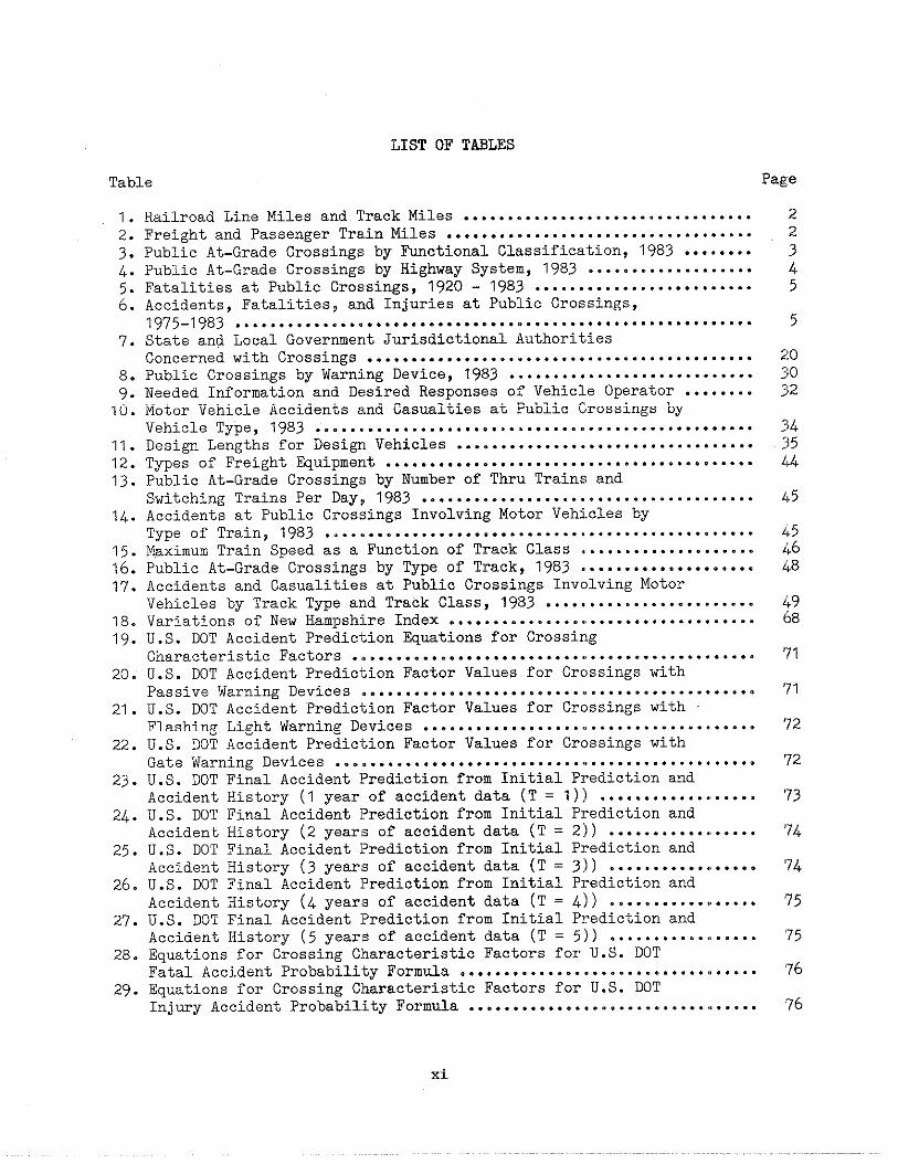
LIST OF TABLES
Table Page
1. Railroad Line Miles and Track Miles .................................2. Freight and Passenger Tr&,inMiles ....................................3. Public At-Grade Crossings by Mctional Classification, 1983 ........4. Public At-Grade Crossings by Highway System, 1983 ...................5. Fatalities at Public Crossings, 1920 - 1983 .........................6. Accidents, Fatalities, aridInjuries at Pub:LicCrossings,
1975-1983 ................................c,..........................7. State and Local GovernmerltJurisdictional l!uthorities
Concerned with Crossings .............................................8. Public Crossings by Warnj.ngDevice, 1983 ............................9. Needed Information and Df>siredResponses of Vehicle Operator ........10. Motor Vehicle Accidents ?lndCasualties at l?ublicCrossings by
Vehicle Type, 1983 .................................................11. Desi~ Lengths for Desi~l Vehicles .................................12. Types of Freight Equipmerlt..........................................13. Public At-Grade Crossings by Number of ThrllTrains and
Switching Trains Per Day,,1983 ......................................14. Accidents at Public Crossings Involving Mo-borVehicles by
Type of Train, 1983 .....!............................................15. Maximum Train Speed as a Fmction of Track Class ....................16. Public At-Grade Crossings by Type of Track, 1983 ....................17. Accidents and Casualitie!sat Public Crossi]~gsInvolving Motor
Vehicles by Track Type a]ldTrack Class, 1983 ........................18. Variations of New Hampsh!LreIndex ...................................19. U.S. DOT Accident Prediction ~uations for Crossing
Characteristic Factors ..............................................20. U.S. DOT Accident Prediction Factor Values for Crossings with
Passive Warning Devices .............................................21. U.S. DOT Accident Predicf;ionFactor Values for Crossings with
Flashing Light Warning Df?vices.....................................22. U.S. DOT Accident Prediction Factor Values for Crossings with
Gate Warning Devices .............................. .................23. U.S. DOT Final Accident l?redictionfrom Initial Prediction and
Accident History (1 year of accident data (T = 1)) ..................24. U.S. DOT Final Accident l?redictionfrom Initial Prediction and
Accident History (2 years of accident data (T = 2)) ...........‘,.....25. U.S. DOT Final Accident l?redictionfrom Initial Prediction and
Accident History (3 years of accident data (T = 3)) ...........4!.....26. U.S. DOT Final Accident Prediction from Initial Prediction and
Accident History (4 years of accident data (T = 4)) ...........(!.....27. U.S. DOT Final Accident Prediction from Initial Prediction and
Accident History (5 years of accident data (T = 5)) ...........<L.....28. Equations for Crossing Characteristic Factors for U.S. DOT
Fatal Accident ProbabilityFormula ..................................29. Equations for Crossing Characteristic Factors for U.S. DOT
Injmy Accident Probability Formula .................................
22345
5
2!030
32
343544
~b5
~k5i+6ih8
ib968
’71
’71
’72
72
’73
’74
’74
’75
’75
76
76
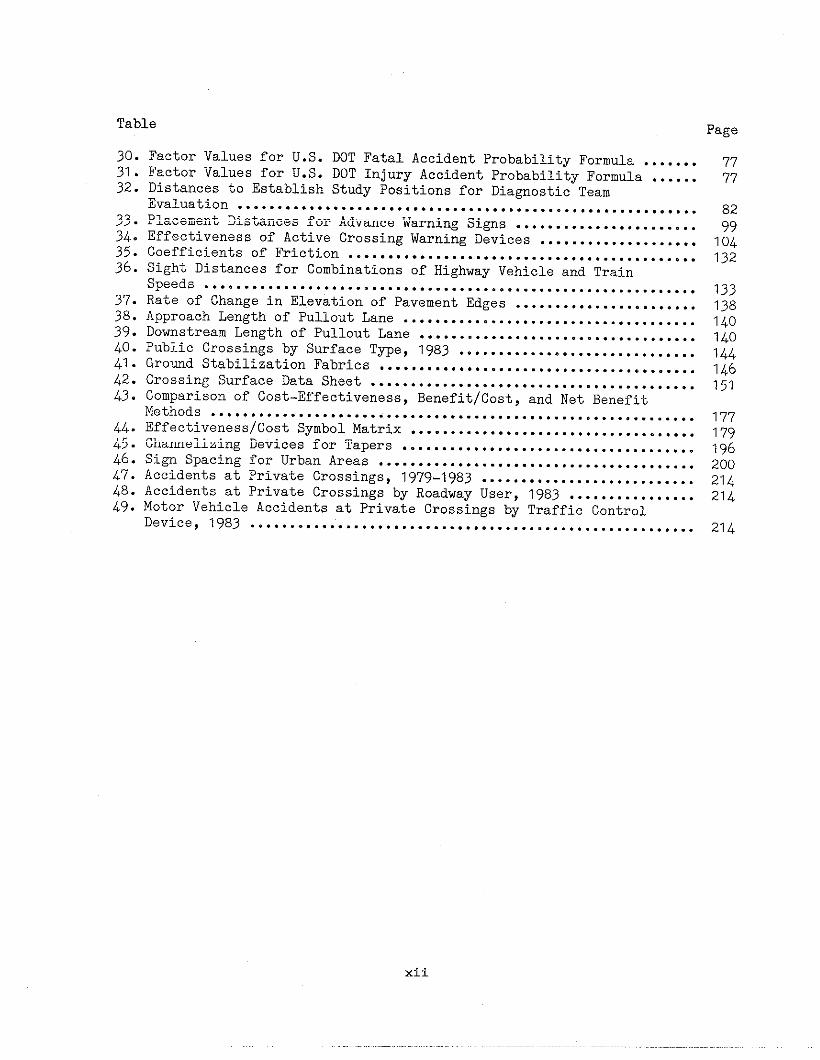
Table Page
30.31.32.
:::
:i:
;::39.40.41.42.43.
:::46.47.48.49.
Factor Values for U.S. DOT Fatal Accident Probability Formula .......Factor Values for U.S. DOT Injury Accident Probability Formula ......Distances to Establish Study Positions for Diagnostic TeamEvaluation ..........................................................Placement Distances for Advance Warning Signs .......................Effectiveness of Active Crossing Warning Devices ....................Coefficients of Friction ............................................Sight Distances for Combinations of Highway Vehicle and TrainSpeeds ..............................................................Rate of Change in Elevation of Pavement Edges .......................Approach Length of Pullout Lane .....................................Dowstream Length of Pullout Lane ...................................Public Crossings by Surface Type, 1983 ..............................Gromd Stabilization Fabrics ........................................Crossing Surface Data Sheet .........................................Comparison”of Cost-Effectiveness,Benefit/Cost, and Net BenefitMethods .............................................................Effectiveness/Cost Symbol Matrix ....................................Channelizing Devices for Tapers .....................................Sign Spacing for Urban Areas ........................................Accidents at Private Crossings, 1979-1983 ...........................Accidents at Private Crossings by Roadway User, 1983 ................Motor Vehicle Accidents at Private Crossings by Traffic ControlDevice, 1983 ........................................................
?77?
8299104132
133138140
140144146151
17?1?9196200214214
214
xii

1. OVERVIEW
This handbook providesinformation on railroad -crossings, characteristics
generalhighwayof the
crossing environment and users, andthe physical and operational imF,rove-ments that can be made at rail.road-highway grade crossings to enhancesafety and operation of both hi.Ehwayand rail traffic over crossing in-tersections. The guidelines ar~dal-ternative improvements presented inthis handbook are primarily thosethat have proven to be effectiv~! andtinat are accepted nationwide. Thishandbook supersedes the Rail.road-——Highway Grade Crossing Handboc)k ofAugust 1978.
A. Backgrowd
1. Introduction to Railroad-Hj.ghwayGrade Crossings
The railroad-highway grade c:ross-ing is unique in that it constitutesthe intersection of two trans;)orta-tion modes, which differ both ~.nthephysical characteristics of theirtraveled ways and in their npera-tions.
Railroad transportation in theUnited States had its beginnin~;dur-ing the 1830’s and became a majorfactor in accelerating the greatwestward expansion of this coutry byproviding a reliable, economical, andrapid method of transport:ition.Today, railroads are major move]?s ofcoal, ores and minerals, grains andother fam products, chaical!3 andallied products, food and kindredproducts,products,ment, andproducts.
lmber and other ~?orestmotor vehicles and (?quip-other bulk materials and
As additional railroad lineswere built and extended, they facili-tated the?establishment and growth oftoms in the midwest and west by pro-viding a relatively rapid means oftranspori,ation of goods and people.Towns d<?pendedon the railroads andtherefore were developed along therailroad lines. The Federal govern-ment and certain States encouragedwestward expansion of the railroadsand financially supported them byland grants and loans. The FederalGovermer]t enjoyed reduced freightrates 01]its cargoes for many yearsas a result of these land grants. Inthe east, railroads were built toserve the existing towns and cities.Many communities wanted a railroadand certain concessions were made toobtain one. Railroads were allowedto build their tracks across existingstreets <indroaclsat-grade, primarilyto avoid the high capital costs ofgrade separations. As people fol-lowed the railroads west, there was aneed fo]” new highways and streetsmost of ~dhich,primarily for economicreasons, crossed the railroads at-grade.
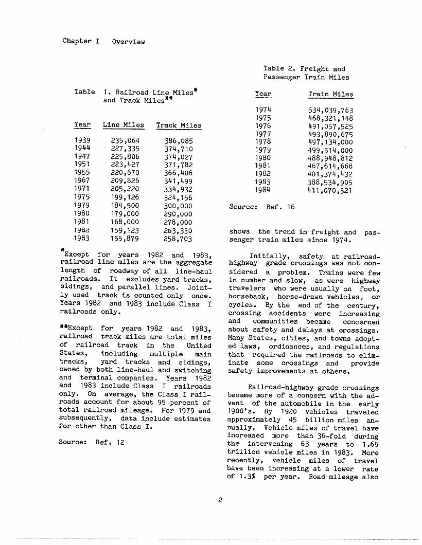
The nwber of railroad, linemiles g]”ewuntil a peak was reachedin 1920 when 252,8U5 miles of rail-road line were in service. The nm-ber of ]~ailroadline miles and trackmiles have been decreasing sir[ce the1930’s as shown in Table 1. Whilethe nwb,ar of railroad 1ine and trackmiles have beetldecreasing continu-ously at about 2 percent per yearduring the past few years, and thenmber ~f train miles operat,ed hasgone up and down with the ~luctua-tions in industrial activity, therehas been an overall decline in trainmiles. ‘Thehea~riestdecline has beenin passenger train miles. Table 2
1
.-,.,
Chapter I Overview
Table 2. Freight andPassenger Train Miles
Table
Year
1939lg4419471951195519671971197519791980198119821983
1. Railroad Line Miles*and Track Mile~**
Line Miles
235,064227,335225,806223,427220,670209,826205,220199,126184,500179,000168,000159,123155,879
Track Miles
386,085374,710374,027371,782366,406341,499334,932324,156300,000290,000278,000263,330258,703
*~xcept for years 1982 and 1983,railroad line miles are the aggregatelength of roadway of all line-haulrailroada. It excludes yard tracks,sidings, and parallel lines. Joint-ly used track is touted only once.Years 1982 and 1g8S include Class Irailroads only.
**Except for years 1982 and 1g83,railroad track miles are total milesOf railroad track in the UnitedStates, including multiple maintracks, yard tracks and sidings,owned by both line-haul and switchingand terminal companiea. Years lg82and 1983 include Class I railroadsonly. On average, the Class I rail-roads account for about 95 percent oftotal railroad mileage. For lg7g andsubsequently, data include estimatesfor other than Class 1.
Source: Ref. 12
Year
19741975197619771978197919801981198219831984
Source: Ref. 16
Train Miles
534,039,763468,321,148491,057,525493,890,675497,134,000499,514,000488,948,812467,614,668401,374,432388,534,905411,070,321
shows the trend in freight and pas-senger train miles since lg74.
Initially, safety at railrOad-highway grade crossings was not con-
sidered a problem. Trains were fewin number and slow, as were highwaytravelers who were usually on foot,horseback, horse-dram vehicles, orcycles. By the end of the century,crossing accidenta were increasingand communities became concernedabout safety and delays at crossings.Many States, cities, and tows adopt-ed laws, ordinances, and regulationsthat required the railroads to elim-inate some crossings and providesafety improvements at others.
Railroad-highwaygrade crossingsbecame more of a concern with the ad-vent of the automobile in the early1900’s. By 1920 vehicles traveledapproximately 45 billion miles an-nually. Vehicle miles of travel haveincreased more than 36-fold dwingthe intervening 63 years to 1.65trillion vehicle miles in lg83. Morerecently, vehicle miles of travelhave been increasing at a lower rateof 1.3% per year. Road mileage also
2

grew during the 63 years tO approxi-mately 3.88 million miles in 1983.
The number of railroad-highwaygrade crossings grew with the growthin highway miles. In cities andtoms , the grid method of laying outstreets was utilized, particularly inthe midwest and west. A CrOSSingover the railroad was often providedfor every street, resulting in aboutten crossings per mile. In 1983,there were 379,611 total intersec-tions of vehicular and pedestriantraveled ways with railroads. Thisequates to approximately 2.4 crOss-ings per railroad line mile.
Crossings are divided intc,cate-gories. Public crossings are!thoseon highways waler the jurisdictionof, and maintained by, a public au-thority and open to the travelingpublic. In 1983, there were 242,980public crossings, of which 2!05,339were at-grade and 37,641 were gradeseparated. Private crossin~;s arethose on roadways privately Owrledandutilized only by the land ow~ler orlicensee. There were 133,011 I)rivatecrossings in 1983. Pedestrian crOss-ings are those that are used solelYby pedestrians and there were?3,620pedestrian crossings in 1983.
Sixty-three percent, 128,1162,ofpublic at-grade crossings were 10cat-ed in rural areas, compared to 76,877in urban areas. For both url)anandrural areas, the majority of crOss-ings are located on local ro:ids asdepicted in Table 3. Twent:!-threepercent of public at-grade crnssingsare located on Federal-aid highwaysas shown in Table 4. Fiftee]o per-cent, 32,200, are located on Statehighways.
The most important singl’= sta-tistic affecting the occurrence ofaccidents at railroad-highway grade
3
Chapter I overview
Table 3. Public At-Grade Crossingsby Functional Classification, 1983
Rural-------------------------------------
Functional Classification Nwber
Interstate*Other principalMinor arterialMajor cc,llectorMinor cc,llectorLocalNot reported
Total
20arterial 1,568
4,63313,79313,29695,108
4U
128,462
Urban--------------------------------------FunctiorlalClassification Nmber
Interstate* 95Other fr,eeway/expressway 529Other pl.incipalarterial 7,472Minor al-terial 12,837COllectnr 11,475Local 44,469
Total 76,877
*CrOssings classified as ‘vlnter-statel’ are typically located onraps.
Source: Ref. 11
crossings is the exposure inclex, theproduct of annual train miles andvehicle miles, divided by 10 to the18th power for convenience. The expo-sure index quantifies the interactionbetween railroad and highway traffic,and provides a suitable base forassessing trends inFigure 1 illustratesexposure index.
crossin$;safety.the trend in the

Chapter I OveTview
Table 4. Publicby Highway
Highway System
Interstate
At-Grade CrossingsSystem, 1983
Nmber
129Federal-aid primary 10,182Federal-aid urban 13,3g8Federal-aid secondary 24;193Non-federal-aid 157,394Not reported 43
Total 205,339
Note: Crossings classified as ltlnter-state” are typically located onraps.
Source: Ref. 11
2. Safety and Operations at Railroad-Highway Grade Crossings
National statistics on crossingaccidents have been kept since theearly 1900!s as a result of the re-quirements of the Accident ReportsAct of lg10. The Act required railcarriers to submit reports of acci-dents involving railroad personneland railroad equipment, includingthose that occurred at crossings.Not all crossing accidents were re-ported because the railroads wererequired to report only those acci-dents that resulted in:
0
0
0
a fatality;
an injury to a person sufficientto incapacitate him Or her for aperiod of 24 hours in the aggre-gate during the 10 days immediat-elyfollowing; or,
more than $750 dmage to railroadequipment, track or roadbed.
800
700 r }
Iv ~600 ,
500
1
400
300 A /“
200 P,
100
I ! 1 1 1 I I I1920 1930 1940 1950 1960 1970 1980
Year
Figure 1. Crossing Exposure Index
These reporting requirementsremained essentially the sae until1975 when the Federal Railroad Admin-istration (FRA) redefined a report-able railroad-highwaygrade crossingaccident. Under the new guidelines,any impaCt “between railroad On-trackequipment and an automobile, bus,truck, motorcycle, bicycle, fam ve-hicle, pedestrian or other highwayuser at a rail-highway crossingt~1must be reported.
Table 5 gives the number Offatalities occurring at public rail-road-highway grade crossings from1920 to lg83. Also shown separately
----------
1Rail-Highway Crossing Accident/Incident and Inventory Bulletin NO.Calendar Year 1983, Washington, DC:Federal Railroad Atiinistration lg84.

Chapter I Overview
Table 5. Fatalitie!3at Public Crossi]~gs,1920-1983
AllYear Fatabties.— —
1920 1,7911921 t,7051922 1,8101923 2,2681924 2,1491925 2,2061926 2,4911927 2,3711928 2,566i929 2,485
1930 2,0201931 1,8111932 1,5251933 1,5111934 1,554i935 1,6801936 1,7861937 1,8751938 1,5171939 1,398
Source: Ref.
MotorVehicleFatalities
1,2731,2621,3591,7591.6881;7842,062i,9742,1652,085
1,6951,5801,3101,3051,3201,4451,5261,6131;3111,197
11 and 13
AllYear Fatalities——
1940 1,8081941 1,9311942 1,9701943 1,7321944 1,840i945 1,9031946 1,8511947 1,7901948 1,6121949 1,507
1950 1,5761951 1,5781952 1,4071953 1,494g ;,303
,4481956 1,3381957 1,3711968 1,2711959 1,203
are fatalities resulting from collis-ions involving motor vehicles. Ta-ble 6 provides data on the nmbe!r ofaccidents, injuries and fatalities atpublic railroad-highway grade cross-ings for the period from 1975 - 1983.Accidents and injuries from 1Si20tO1974 are not provided because not allaccidents and injuries were recluiredto be re~rted during those yea~,s.
The motor vehicle fatalit:{sta-tistics are depicted graphically inFigure 2 which clearly demonstratesthe overall improvement in safefcy at
crossings. The exposure inde:~prO-vides a means by which crossing sta-tistics can be compared thrOllghOUtthe years. The fatality ratio (num-ber of fatalities divided bY theexposure index) for the years 1920through lg83 is also depicted inFigure 2.
MotorVehicleFatalltle5
1,5881,6911,6351,3961,5201,5911,5751,5361,3791,323
1,4101,4071,2571,3281,1811.3221;2101,2221,1411,073
Al!Year Fatalities—c
1960 1,3641961 1,2911982 1,2411963 1,3021964 1,5431965 1,5341966 1,7801967 1,6321968 1,5461969 1,490
1970 1,4401971 1,3561972 1,2601973 1,1851974 1,2201975 978i976 1,1141977 9441978 1,0211979 834
1980 7881981 6971982 5801983 542
VeticleFatatiVes——
1.2611,1721,1321,2171,432!1,434.1,6571,52CI1,44:11,381
1,36;!1,2671,1901,0771,12878897[1846g2g72i,
70862S5264%3
Table 6,,Accidents, Fatalities,*andInjuries at Public Crossings,
1975-1983
year Ac{>idents Fatalities Injuries_ ——
1975 1“1,354 9781976 12,114 1,1141977 12,299 944lg78 12,435 1,0211979 11,552 8341980 ‘3,763 78a1981 3,546 69719a2 7,158 5801983 6,562 5Q2
*Including motor vehiclemotor vehicle accidents.
Source: Ref. 11
4,16a4,8314,64g4,2564,1723,6623,1212,5082,467
and non-
5
Cnapter I Overview
1920-193(—
kFatality
epression
1
1935-
VeryFew Improvements‘—
II141— FederalAidPrograms
VarPeriod—UttleActivit~
M
PeriodofIncreasedFederalK
i 920 1930 1940
Figure 2. Historical
+
?s
I
+
+
1950
Year
Phases of
1960 1970
Crossing Safety
1980
Programs
5
Chapter I Overview
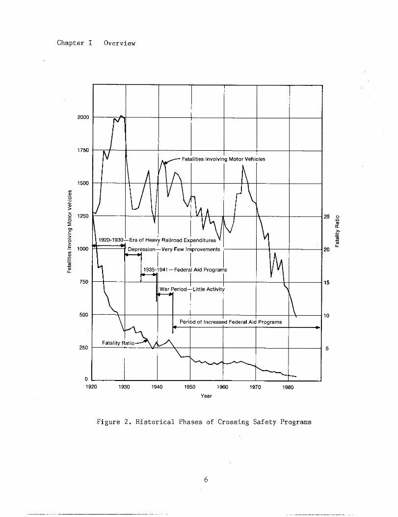
The variation in the fatalityratio appears to be related to var-ious occurrences over the years.From 1920 to 1930, railroad expendi-ture for the construction of gradeseparations and crossing active traf-fic control devices was extensive.During the early four year period ofthe depression, railroad expendituresfor crossing improvements lagged, andthe fatality ratio remained about thesame. Starting in 1935 some specialFederal progrms were initiated tOimprove crossing safety and. thefatality ratio decreased. During thewar period of the 1940’s, crcssiWimprovement work was greatly reducedand the fatality ratio increasedslightly. Since 1946, Federal-aidhas increased and the fatality ratiohas correspondingly been decrea~sing.
During the period between 1960and 1967, the fatality ratio reu~inedalmost constant; however, the rlmberof fatalities increased as dicl theexposure index. This was in spj.teOfcontinual Federal funding for gradeseparations and crossing traffic!con-trol device improvements. A nat,iOnalconcern for crossing safety was de-veloped as witnessed by the h[)ldingof national conferences to addresathe increase in casualties. Th<?U.S.Congress responded by establishing acategorical funding program forcrossing safety improvements ill the1973 Highway Act. This categoricalsafety progrsm was extended ill thelg76 Highway Act, and the 1978 and1g82 Surface Transportation Acts.The result of this safety progr+m andother emphases On crossing saf!?tyisillustrated in Figure 2 which showsthe drsmatic reduction in the ]~mberof fatalities involving motor vehi-cles.
In 1983, approximately 18.:3mil-lion motor vehicle traffic accidentsoccurred. Crossing accidents ac-
couted for 0.03% of all moto]:vehi-cle accidents o)tpublic roads. How-ever, the severity of crossing acci-dents demands s,pecialattention. In1983, there were 483 motor vehiclefatalities at crossings and a totalof 42,584 motor vehicle fatalities.Thus, crossing fatalities acoountedfor 1.1% of all motor vehicle fatalit-ies. Orle out of every 430 vehicleaccidents resulted in a fatality, butone out of every 12 crossing acci-dents resulted in a fatality.
Whil.e railroad - highway gradecrossing accidents account for only asmll portion of all highway acci-dents, they represent a large portionof all r:~ilroadaccidents. In 1983,there wer>e1,073 fatalities resultingfrom all. railroad accidents / inci-dents. of these, 53.6%, 575, oc-curred at crossings, both public andprivate.
In additian to the possibilityof a collision between a train and ahighway user, a railroad - highwaygrade crnssing presents the possibil-ity of an accident that does notinvolve “atrain. Non-train accidentsinclude: rear-end accidents in whicha vehicle that has stopped at acrossing is hit from the rear; colli-sions wi’Lhfixed objects such as sig-nal equi]?mentor signs; and, c[on-col-lision accidents in which Z[driverloses co]mtrolof the vehicle.
These non-train acciderlts arealso a c>ncarn particularly with re-gard to the transportation of hazard-ous materials by truck and the trans-portation of passengers, especiallyschool buses. These “special Vehi-
cles” are, in many Statas, x.equiredby law to stop at all crossings andlook for a train before proceedingacross the tracks. The driver Of avehicle that is following a specialvehicle may not expect to stop and
7
Chapter I Overview
maY rear-end the vehicle, perhapsresulting in a catastrophic accident.
While safety is a primary cOn-cern, railroad-highway grade crOas-ings affect the public and railroadsin other ways. In the 19th centurymost communities and cities welcomedand actively encouraged the ~Onstruc-tion of railroad lines to and withinthe community. As the benefits ofthis transportation service were re-alized, the communities and the rail-road system within the communitiesgrew. Today, highway-oriented trans-portation provides much of the ser-vice needed for commercial and Otherland uses in and near the centralcity. Newer industrial developmentsthat need rail transportation arefrequently located in outlying areas.
Historically, railroads cme in-to the centers of communities becausethe railroads were first or becausethe community wanted the railroad toenter to provide transportation tothe rest of the country. In todaytsenvironment, especially with high ve-hicular traffic, conflicts have aria-en over the railroads’ location incentral cities. From the eomunityviewpoint, the railroad is now adividing force providing delays~ con-gestion, and concerns over emergencyvehicle response while traina aremoving through, blocking mny streetcrOssings. Some communities imposespeed restrictions on the trains,thereby exacerbating the situation ofdelays because trains take longer toclear crossings.
From the railroad viewpointsspeed restrictions are undesirablebecause of the delays incurred bytrains ?lOwing down to pass throughthe comunity. However, the centralcitY location has an advantage forthe railroad. Its right-of-way maybe attractive to power companies who
wish to reach electric customers inthe city, hence railroads may leasespace for electric power transmissionlines. Also, with the new develop-ment of fiber optic cables for highcapacity comunicat ions services,comunicationa Comon carriers arealso finding railroad rights of wayinto center cities very attractive.Thus, On the positive side, commun-itiesand railroads are finding mutualadvantages in communicating and coop-erating with each other on thismutual situation.
B. Railroad-High~y Grade CrossingPrOgras
The first authorization of Fed-eral funds for highway constmctionoccurred in 1912 when the U.S. COn-gress allocated $500,000 for anexperimental rural post road program.The Fedaral-Aid Road Act of 1916 pro-vided Federal funds to the States forthe constmction of “rwal postroads”. These finds could be expend-ed for railroad-highway wade cross-ing safety improvements as well asother highway constmction. TheStates had to match the funds on a50-50 basis and they oftan requiredthe railroads to pay the state,s 50%share and sometimes mre. The Feder-al Highway Act of 1921 provided fundswith similar provisions except thatthe expenditure of Federal funds wasrestricted to a limited connectedsystem of principal roads now calledthe Federal-aid primry highway sys-tem.
The Depression era of the 1930’sbrought about a change in railroadand highway traffic volmes and cre-ated a nead for Federal assistance topromote safety as well as to provideemplowent throughout the nation.Congress passed the National Indus-trial Recovery Act in 1g33 that,
8
among other things, authorized thePresident to provide grants totaling$300 million to the States to be usedin paying any or all of the costg foreliminating the hazards of railroad-highway grade crossings. The Statesdid not have to provide matchingfwds and the improvements did nothave to be mde at crossings on theFederal-aid highway system.
The Hayden - Cartwright Act of1934 authorized additional funds forthe construction of railroad-highwaygrade separations and traffic coctroldevices at crossings. Federal funds
were available for initial construc-tion costs but not for maintenancecosts nor for right-of-way cc,sts.Other Federal-aid highway funds wereprovided in the Emergency Relief Ap-propriation Act of 1935, the Authori-zation and Amentient Act of 1936~ theFederal-Aid Highway Act of 1938, andthe Federal Highway Act of 1940. Inspite of these efforts to eliminatecrOssings, the number of crossingsactually increased due to nwe!roushighway construction projects beingcompleted during the sme period.
The Federal-Aid Highway Act. of1944 authorized the expenditure! ofFederal funds for Federal-aid l!igh-ways in urban areas and provided forthe designation of a Federal-aid sec-ondary highway system and a nationalsystem of Interstate Highways. Whilethe States had to provide 50Z mntch-ing funds for expenditures on theprimary, secondary, and urban hi:;hwaysystems, the entire cost for theelimination of railroad-highway ~;radecrossing hazards on the Federal.-aidsystem could be paid from Fecleralfunds. However, no more than 50% oftbe right-of-way and property damagecosts could be paid with Fecleralfunds. In addition, no more tharl10%of the total funds apportioned toeach State in any year could be used
Chapter
for crossing projects onable basis up to 100%.
I Overview
a rei:mburs-
In the 1960’s the InterstateComerce Cwission conducted an in-vestigation of railroad-highwaygradecrossing safety. It conciuded thatthe public was now responsible forcrossing safety and recommended thatCongress take appropriate action bystating:
Sinc6? the Congress has the au-thorj.tyto promulgate any neces-sary legislation along this lineit is recommended that it giveserious study and considerationto erlactmentof legislation ~flitha view to having the public in-cluding the principal users,assume the entire cost of rail-high~ray grade crossing improve-ments or allocating the costsequitably between those bene-fited by the improvements.2
In ‘1970, the U.S. Congresspassed two acts, the Highway SafetyAct and i,heFederal Railroad SafetyAct, that conte,inedspecific provi-sions concerning railroad - highwaygrade crossings. The Highway SafetyAct authol>izedtxo demonstration pro-jects, one for tke elimination of at-grade crossings along the NortheastCorridor high speed rail passengerroute frorkWashir,gton, D.C. to Bos-ton, ~ and the other for the elimin-ation or :Lnstallationof traffic con-trol devices at public crossings inand near Greenwood, SC. The Act pro-vided $3’1 million for these demon-stration projects.
-----------
2Preventi0n of Rail - HighwayGrade Crossing Accidents InvolvingRailway Trains and Motor Vehicles,Washington, DC: Interstate CcmerceComissio]~, November 1962.
9
Chapter I Overview
The Railroad Safety Act of lg70required the Secretary of Transporta-tion to undertake “... a comprehensivestudy of the probla of eliminatingand protecting railroad grade cross-ings“ and to provide “recommendationsfor appropriate action includi~, ifrelevant, a recommendation for equi-table allocation of the economiccosts of any progrm proposed as aresult of such study!!. Similarly,the Highway Safety Act of lg70 calledfOr “...a full and complete investi-gation and study of the problem ofprovidi~ increaaed highway safety atpublic and private ground-level rail-highway crossings ... iucluding theestimate of the cost of such a prO-grm” .3
The Federal Highway Administra-tion (FHWA) and the Federal RailroadAtiinistration (FRA) preparad a two-part report to satisfy the require-ments of the legislation. Part Idiscussed the crossing safety problaand Part II provided crossing im-provement recommendations, one ofwhich was a Federal finding prograexclusively for crossings. The Sec-retary also recouended that theDepartment of Transportation, in co-operation with the railroad industryand appropriate State agencies, de-velop a national inventory of crOss-ings and a unifom national nmberi~Systa of crossings. In addition,the Secretary recomendad that rail-road-highway grade crossing safetyresearch be emphasized and thateffOrts tO educate drivers regardingthe potential hazards of crossings befurthered.
----------5Railr0ad-HighWaY Saf‘ty) Part
I: A Comprehensive Statement of theProblem, A Report to Congress, Wash-ington, DC: U.S. Department OfTransportation, November 1971.
Based on the recommendations ofthis study, the U.S. Congress, in theHighway Safety Act of 1g73, estab-lished a categorical safety prografor the elimination of hazards atrailroad - highway grada crossings.Section 203 of the Act authorized,from the Highway Trust Fud, $175million for crossing improvements onthe Federal-aid highway system. TheFederal share of improvement cOstswas set at 90%. This Act also estab-lished funds for other categoricalsafety pro~as that could be usedfor crossing improvements at theStatea’ discretion. Section 230 es-tablished the Safer Roads Demonstra-tion Progrm that provided fundingfor safety improvements off the Fed-eral-aid highway systa. Funds mderthis program were available for threetypes of safety projects: to elimin-ate hazards at railroad-highwaygradecrossings; to improve highway urkingand signing; and, to eliminate road-side obstacles. The Pavement MarkingDemonstration Progrm, Section 205,provided finds for pavement ~rkingson any road. The Federal-Aid HighwayAmendments of 1974 added Section 21g,which provided funds for the con-struction, reconstwction, and im-provement of highways off the Feder-al-aid highway system.
In 1975, all public and privatecrossings had been smveyed in theUs. DOT/AAR National Rail-HighwayCrossing Inventory progra. Thisinvento~ showed that the majority ofcrossings, 77%, were located off theFederal-aid highway systm and thuswere not eligible for improvementwith Federal funds from the Section203 pro~m. Thus, in 1976 the U.S.Co%ress provided funding for allpublic crossings. The legislationauthorized an additional $z50 millionfrom the Highway Trust Fwd forcrossinzs on the Federal-aid highwaysystm and $168.75 million from the
10

Chapter I Overview
general fund for crossings off theFederal-aid highway systa.
The Surface TransportationAssistance Act of 1978 continued theSection 203 categorical funding pro-gra by providing $760 million forsafety improvements at any publiccrossi~ -- the distinction betweenon and off the Federal-aid highwaysystem was eliminated.
In 1982, Congress again contin-ued the railroad-highwaygrade cross-ing safety tiprovement progrm in theSurface Transportation AssistanceAct. The Act provided $760 u[illionfor crossing safety projects duringthe four fiscal years 1983 through1986.
The Section 203 funds are appor-tioned to the States in the followingmanner: 50% of the money is appor-tioned accovding to the ratio of thenmber of public crossings in[ eachState to the total nwber of publiccrossings in the entire country. Theremainder is apportioned on the!basisof area, population and road mileage.The Federal funds are eligible for90Z of the project costs and ulay beused for any public crossing, on oroff the Federal-aid highway nystem.For more information on the rc!quire-ments governing the expenditc~re ofFederal funds on grade crossir~g im-provements, see Chapter VI, Im~}lemen-tation of Projects.
Other regular Federal-aiclhigh-way funds, such as those frc)m theprimary, secondary, and urbarlprog-rms, may also be used for creasingimprovements on the Federal-aiclhigh-way system. These improvements caninclude the installation of standardsigns and pavement markings, theinstallation or upgrading of activetraffic control devices, crossj.ngil-lminatiOn, crossing surface inlprOve-
menta, new grade separations and re-construction of existing grade sepa-rations, crossing closures or removalof existing crossings, and crossingeliminat.ions by relocation of high-ways and/or relocation of railroads.For projects to eliminate or reducehazards,at crossings, the State mayutilize Federal funds for 100% of theprelimiz~aryengineering and construc-tion costs. Right-of-way costs arefunded at 75%. Most projects requireno additional railroad share ofcoats.
The Federal-Aid Highway Act oflg73, section 163, established a dem-onstration progra to eliminate rail-road-highway co~licts in specifiedurban nreas. Additional funds wereprovided in the Federal-Aid HighwayAmenherlts of 1974, the National MassTransportation Assistance Act of1974, the Federal-Aid Highway Act of1g76 aridthe Surface TransportationAssistarlceActs of 1978 and 1982.
These demonstration projects areintended to determine the feasibilityof increasing highway safety by therelocat?Lon,consolidation, or separa-tion of rail lines in center-cityareas. The funds are available for95~ of the project costs, with theState or local governments providingthe matching 5$.
These demonstrateion projectswere designated for Elko, NV; Lin-coln, NE; Wheeling, WV; Blue Island,Carbondale, Dolton, East St. Louisand Sp:”ingfield, IL; New Albany,Terre Haute, Lafayette, and H-end,IN; Anoka, MN; Brownsville, TX-Mata-moros, Mexico; Greenville, TX,;Metai-rie, LA; Augusta, GA; and Pine Bluff,AR.
In the Surface TransportationAssiataIlce Act of 1982, Title II,Section 202, Congress authorized the
Chapter I Overview
expenditure of $7.05 billion for thecontinuation of the on and off systemhighway bridge replacement and reha-bilitation program. All bridges car-rying highway traffic on publicroads, regardless of ownership ormaintenance responsibility, are eli-gible for improvement uder this pro-gram. This includes highway bridgesowned by railroads.
In addition to administeringFederal funds for improvements atrailroad-highway grade crossings, theFHWA is active in conducting researchOn crossings. The FRA is also activein conducting research pertaining torailroad - highway grade crossings.More detailed information on crossingresearch is contained in Chapter X,Supporting PrOgras.
Many States have been active incrossing improvement programs fordecades. States have been responsi-ble for initiating and implementi~projects under the various Federalf~ding progrms. In general, mostStates once required the railroad orthe local goverment to provide thefuds needed to match the Federalcontribution. However, in the 1930’ssome States began to apportion ftian-cial responsibility for crossingimprovements baaed on the benefitseach, the public (highway agency) andthe private (railroad) received, fromthe project.
California was the first Stateto establish a State crossing protec-tion fund. In 1953, the Public Util-ities Commission was authorized bylegislation to expend or allocatefuds from the State Highway UserFwd , or any other fud, to assistthe cities and counties in payingtheir allocated portion of the costsfor the installation of active traf-fic control devices on non-Federal-aid highways and streets. In 1g57
California established a grade separ-ation fund with an initial appropria-tion of $5 million per year. Thepurpose of the fund was to eliminateexisting at-grade crossings by con-structing new grade separations or byimproving existing grade separations.Eighteen additional States have sinceestablished separate finding prograsfor crossing improvements. AppendixA contains a brief description of theState funding programs as of lg84.
States may also utilize otherState finds for crossiag improvementsand to provide the required 10% matchfor projects funded mder the FederalSection 203 program. In addition tofinancing cOsts directly associatedwith the improvement of railroad-highway wade crossings, al1 Statescontribute incidentally to the cross-ing components. In general, forcrossings located on the State high-way system, States provide for theconstruction and maintenance of thehighway approaches and for trafficcontrol devices not located on rail-road right-of-way. Typically, theseinclude advance warting signs andpavement markings. Presently, 17States have programs to contributetowards the maintenance of flashioglights, gates, track circuitry,crossing surfaces, and crosshucks.These States are listed in AppendixB. More information on State ma.tite-nance programs is included in ChapterVII, Maintenance Progrm.
States are involved in otherareas of crossing safety improvementbesides the financial contributionstowards improvement projects. Gov-erment agencies and the nation’srailroads are participating in Oper-ation Lifesaver programs which havebeen established in forty - fourStates. Operation Lifesaver Programsare designed to improve crossingsafety through education of the pub-
lic regarding the hazards of CP099-i~9, promotion of engineering im-provements, and enforcement of wtor-i9t traffic law9 at crossings. Thegeindividual State programs are coor-dinated on the national level by theNational Safety Council. More infor-mation on Operation Lifegaver isincluded in Chapter X, Sup~rti~Programs.
Some States also conduct rail-road-highway grade crossing research,utilizing Highway Planni~ Research(HPR) funds made available by theFHWA. Other studies are conductedin-house or on a contractual basiswith consultant firms and diversi-ties and are financed from regularState highway funds.
Some local government agenciesparticipate in railroad-highwaygradecrossi~ safety by providing thematching funds for improvement pro-jects constructed waler the Section203 Federal program. Localities havebeen contributing for decades throughthe installation and maintenance oftraffic control devices located inadvance of crossings. Some citiesand counties conduct safety studiesat specific crossing locations.
The railroad industry has, his-torically, contributed greatly to theimprovement of railroad-highwa,ygradeCrogsings. Until the advent of theautomobile in the early 1900!s therailroads were considered to be pri-marily responsible for safety atcr09sings. After that, the conceptof joint responsibility between pub-lic agencies and private agencies,t.e. the railroads, began to emerge.A9 discussed previously, the Federalgoverment and State governments be-gan to contribute financially towardscrossing improvement projects, thusaccepting part of the responsibilitythat originally had been placed sole-
Chapter
ly upon the railroads.of whc, is responsibleaspects of the crossingtinues to be refined.
I Overview
The questionf’~r what
program cOn-
While public agencies have es-tablisb,edfunding programs for cross-ing imF,rovements,railroads l~avecon-tinued to contribute financially aswell. In some cases, the railroadmay pay all or a portio]n of therequired retching funds of a FederalSection, 203 project in excha~e forsome other benefit such as the clO-sure Clf an adjacent crossi]ng. &nyrailroads have established right-of-way clearance programs that assist intiprovi,ng quadrant sight distance atcrossin~gs.
At present, costs for mainte-nance C,fcrossing trsffic co]~trolde-vices and crossing surfaces are pri-marily fwded by the railroads.Crossing devices and surfaces areusually maintained by railroad workforces because they are i]~tegratedinto the signal system regulatingtrain operations and into the physi-cal railroad track structme. Also,labor ~reements generally specifythat union members are to perfomthis type of work. A survey by theAssociation of American l?ailroadsdetemined that annual maintenancecosts associated with active trafficcontrol devices can range fr{>m$1~200to $3,000 per crossing in 1982 dol-lars dependent upon the complexity ofthe system. With over 55,000 cross-ingS with active trtific controldevices, the annual expend:Lture byrailroads for crossfig maintenance issubstantial, ,#ithminimal ct>stshar-ing by other involved parties, suchas Federal, State, or local govern-ment agencies.
Railroads also work wif;h localcommunities to alleviate operationalconeems at railroad-highway grade

Chapter I Overview
crossings. For example, locationsfor train crew changes can be madeoutside of city limits to avoidblocking crossings by non-movingtrains. Railroads conduct some re-search for the purpose of identifyingnew technologies and furthering newconcepts regardi~ crossing safetyand operations.
The Association of AmericanRailroads (AAR) has been active incrossing programs and has establisheda separate State-Rail Programs Divi-sion within its Operations and Main-tenance Department. This Divisionprovides information to the U.S. Con-gress and the U.S. Department ofTransportation to assist in theestablishment and atiinistration ofcrossing programs. Railroad inter-ests and concerns regarding crossingsare typically coordinated through theAAR office. The State-Rail PrograsDivision has appointed a railroad em-ployee in each State to serve as theAAR State Representative on crossingprograms. A list of these represen-tatives is available from the AAR.
Other railroad related companiesalso participate in crossing safetyprogr~s. The signal suppliers andthe manufacturers of crossing sur-faces provide guidance for the selec-tion of a specific device or crossingsurface. In addition, these compan-ies are actively conducting researchto improve their products.
Other groups and organizationsare actively involved in railroad-highway grade crossing safety pro-grsms. These include the NationalSafety Council, the National Trans-portation Safety Board, the AmericanRailway Engineering Association, theRailway Progress Institute, theTransportation Research Board, andvarious other highway safety organi-zations. The responsibilities of
these organizations are discussed inthe next section.
C. Responsibilities at Railroad -H~hway Grade Crossings
An issue that is as old as thegrade crossing safety problem itselfis that of responsibility. MOshould provide and pay for the traf-fic control devices at railroad-high-way grade crossings?
During the years from 1850 to1870, there was tremendous growth inpopulation that followed the rail-roads west. Consequently there wasneed for new highways and streets,practically all of which crossed therailroads at grade. In most casesthe responsibility for these cross-ings automatically fell upon therailroads. Occasionally, there wereaccidents at crosstigs, but they wereusually not as seriuos as thoseoccurring today.
One of these early accidents,involving the collision of a trainand wagon at Lima, Indiana, resultedin a court suit that eventuallyreached the U.S. Supreme Court in1877. In Centinental Improvement Co.v. Stead, the Court had to deteminewho was liable for the damages in-curred. In its decision the Courtsaid that the duties, rights, andobligations of a railroad company aswell as a traveler on the highway atthe public crossing were “mutual andreciprocal”. It also said that atrain had the right - of - way overcrossings because of its “character”,,,momentum,,, and *1the requirements Of
public travel by means thereof”. Therailroad, however, was bound to givereasonable and timely warning of thetrain’s approach. The Court furtherstated that “those who are crossing arailroad track are bound to exercise
Chapter I Overview
ordinary care and diligence to ascer-tain whether a train is approachi~”.This Supreme Court decision clearlyindicated that there was a responsi-bility upon the railroads tc, warntravelers on the highways c,f ap-proaching trains and a responsibilityof travelers to look, listen and stopfor approaching trains.4
During the late 1890’s, the nm-ber of crossings and the number ofaccidents increased. Many States,cities, and towns dmanded that therailroads take immediate action toeliminate the hazardous crossings andto provide better traffic control de-vices at others to minimize the acci-dents. Nmerous laws, ordinances,and regulations were enacted oradopted to enforce these demnds.There was no unifomity among thelaws, ordinances, and regula.tions.Neither was the division of responsi-bility nor the allocation of costsspecified.
In 1893, the U.S. Supreme Court,in New York & N.E. Ry. v. Town ofBristol, upheld the constitutionalityof a Connecticut statute that re-quired the railroads to pay three-fourths of the costs to improve oreliminate crossings where the highwaywas in existence before the railroad.If the highway was constructed afterthe railroad, the State required therailroad to pay one-half of suchcosts. This so-called “Senior-Junior”principle was followed by the c-is-sions and courts in several States todetemine the railroads’ division ofresponsibility or liability for theconstruction, improvement 0? elimina-tion of crossings. From 1896 to 1935the U.S. Supreme Court adhered to theposition that a State could allocateto the railroads all, or a portfon,
----------41bid.
of the expense or cost for the con-stmction, maintenance, improvement,or elimination of public railroad-highway grade crossings.
The crossing safety problem waschangad greatly by the appearance ofmotor vehicles on the Nation’s high-ways arid streets in 1893. As thenumber of motor vehicles, highwaymileage, and railroad trackage in-creaaed, so did the number of cross-ings ar[d crossing accidents. Thedmands for elimination of crossingsgrew str,ongernationwide. Besause ofthe dominance and financial status ofthe railroad industry during thisperiod, the public, State legislativeand regulatory bodies, and most afthe coursts,did not hesitate to placethe majcjr, or entire, responsibilityfor crossing separations and improve-ments on the railroads. By 1915 therailroads were beginning to feel theimpact of the crossing safety prob-lem, a~kdestablished a national com-mittee to study the problem. Duri~the period from 1915 to 1924, thiscommittee, the National Safety Coun-cil, arid the Amarican Railway Asso-ciation angaged in extensive publiceducatic)nprogrms to reduce the num-ber of accidents at crossings.
The depression era of the 1930’sbrought about abrupt and varyi~changes in the volmes of rail andhighway traffic, which contributed tochanges in the responsibility forcrossing improvements. A new idea ofpublic r,espOnsibilitywas enhanced byCongress in its passage of theNational Industrial Recovery Act of1933 and.The Hayden-Cartwright Act of1934 that provided funds for the con-structicn of railroad-highway gradeseparations and the installation ofcrossing traffic control devi(>es.
This expanded Federal highwayconstriction progrsm had a gr{~atdeal
Chapter I Overview
of influence on the U.S. SupremeCourt’s landmark decision in Nash-ville, C. & St. L. Ry. v. Walters in1935. Just-ice Brandeis, writing forLhe majo~ity of the Court, said:
The railroad has ceased to bethe prime instrment of dangerand the main cause of accidents.It is the railroad which nowrequires protection from dangersincident to motor transporta-tiOn.5
In light of that decision, someSkate legislatures, commissions, andCouPts revised their divtsion ofresponsibility criteria, and the re-sulting allocation of costs relatingto crossing safety projects.
The Federal-Aid Highway Act of1944 provided that any railroad in-volved in any crossing improvement?Yoject, paid for entirely or in partwith Federal funds, would be liableto the United States for “a sw bear-ing the same ratio to the net bene-fits received by such railway fromsuch project that the Federal fundsexpended on such project would bearto the total cost of such project”.This subsection also p~ovided thatthe net benefits received by a rail-way should not “be deemed to have areasonable value in excess of tenpercent of the cost of any such pro-ject”. The Commissioner of PublicRoads was authorized to determine therailroad benefits on the basis ofrecommendations made by the Statehighway departments and other infor-nation.6
During the period from 1944 tolg46, many crossing safety projects
----------
51bid.
61bid.
were delayed, or never started, be-cause of prolonged negotiations, ar-gments, and litigation on the issueof railroad benefits. A compromisewas eventually reached whereby eachof the crossing improvement projectswould be classified as being in oneof five general classes. Dependingupon the classification assigned toan individual project, the railroadswould be liable for up to 10% of thecosts of crossing improvements fi-nanced with Federal - aid highwayfunds. The FHWA later modified thispolicy and presently the railroadsare required only to share in 5 per-cent of the costs of certain types ofcrossing work on Federal-aid highwayprojects.
In the early 1960’s, the I~ter-state Commerce Comission completedan investigation to detemine whatactfon should be taken to preventcrossing accidents. In its reportand accompanying orde~, the C~is-sion said that:
For practical reasons costs as-sociated with crossing safetyimprovements should be borne bypublic funds as users of the
crossing plus the fact that itis the increasing highway traf-fic that is the controlling ele-ment in accident exposure atthese crossings.
The Commission also said that:
In the past it was the rail-road’s responsibility for pro-tection of the public at gradecrossings. This responsibilityhas now shifted. Now it is thehighway, not the railroad, andthe motor vehicle, not Vne trainwhich creates the hazard andmust be primarily responsiblefor its removal. Railroads wereSn operation before the problem
16
presented itsslf and if tl~e in-creasing seriousness is a resultof the increasing devslop]uentofhighways for public US(:, whyshould not the cost of gradecrossing protection be assessedto the public?
The Commission found:
That highway users are th,:prin-cipal recipients of the b(?nefitsfollowing from rail - l~ighwaygrade separations and from spe-cial protection at rail-l~ighwaygrade crossings. For thYLsrea-son the cost of installi]lg andmaintaining such separati[>nsandprotective devices is a publicresponsibility and should befinanced with public funds the
ye, .~s highway traffi> de_
During the 1970’s the publicassumed more of the responsibYLlitiesfor financing crossing safe.ky im-provements. Federal highway l{?gisla-tion in 1973, 1976, 1978, 19<30,and1982 provided categorical funds forcrossing safety improvements. Today,an understanding exists that~ becauserailroad-highway grade crossi]lgsin-volve two transportation modes, onepublic and the other private, theirsafe and efficient operation ]:equirestrict cooperation and coordCLnationof the involved agsncies and organi-zations. Public agencies havj.ngre-sponsibilities at an intersectYLon ofthe two modes include the following.
----------7preventi0n *e~~de~~l - ‘w
Grade Crossing In\rolvinKRailway Trains and Motor Vel_,Washington, DC: Interstate CommerceCommission, November 1962.
At
0
0
0
0
At
0
0
~.
0
0
At
0
0
0
0
Chapter I Overview
the Federal Level
Fede:ral H~.ghway Administration(FNA)
Fede:ral Railroad Administration(FRA)
Naticnal Transportation SafetyBoard (NTSB)
National Highway Traffic SafetyAdministration (NHTSA)
the State Level
State highway departments
State departments of transporta-tion
State regulatory agsncies
State highway safety agencies
State departments of public safety
the Total Level
Highl~aydepartment field mainten-ance offices
County road engineer offices
City public works agencies
Law enforcement agencies
Th(?U.S. Department of Transpor-tation (DOT) seeks to ensure that aviable and safe national transporta-tion system is maintained tc trans-port people and goods while makingefficient use of our national re-sources, Three agencies within theU.S. DOT, F~lA, FRA, and NHTSA,activel~r participate in crossingprograms.
Chapter I Overview
The FHWA administers Federallyfuded programs, several of which areavailable for crossing improve:nents.In addition to finds from the Section203 categorical crossing program,funds from the primary, secondary,and urban progrms may be utilized atcrossings. The FHWA apportions thesefinds to the States according to leg-islated formulae and in the mowtsauthorized by Congress for each pro-gram. It establishes procedures bywhich the States obligate the fundsto specific projects. It overseesthe overall implementation of theFederally funded programs.
The FHWA establishes standardsfor traffic control systems at crOss-ings and publishes these in the -=
al on Uniform Traffic Control De-vices. The FHWA has also adopted,for use in Federal-aid highway proj-ects, various design criteria andguidelines developed by AASHTO andother organizations. The FHWA pro-vides technical assistance to theStates through the distribution ofstate - of - the - art handbooks andthrough special training classes.
The FHWA conducts research tosupport the above activities. Typi-cal research ~-nvolvesroad-side traf-fic control devices, accident causa-t%on, program management tools, andaccident countermeasures. All ofFHwA‘S crossing research is coordi-nated wtth FRA and, in some cases FRAcontributes financially to the proj-ects. The FHWA promotes maintenanceof individual State grade crossinginventories and maintenance of thenational inventory by the individualStates.
The FRA maintains the RailroadAccident/Incident Reporting Systathat contains information reported bythe railroads on all crossing acci-dents. The FRA also serves as custo-
d:an of the National Rail-HighwayCrossing Inventory that containsphysical and operating characteris-tics of each crossing. The info--tion is submitted voluntarily by therailroads and States. The FRA workswith other agencies and organizationsin overseeing the submission of theinventory data to ensure accurate andtimely fnformation.
The FRA conducts field investi-gateions of selected railroad acci-dents, including crossing accidents.The FRA investigates complaints bythe public pertaining to crOssingsand makes recommendations to theindustry, as appropriate.
The FRA conducts research toidentify solutions to crossing prob-lems, primarily from a railroad per-spective. Typical research includesprogr~ management tools, train-bornewarning devices, and track circuitryLmprOvements. Research is coordinat-ed with FHWA and In some cases, FHWAcontributes financially.
Both the FHWA and FRA have fieldoffices located throughout the coun-try, which collaborate with the Statehighway agencies, and the individualrailroads, respectively, on a day-to-day basis. They ensure that policiesand regulations are effectively im-plemented and provide feedback toheadquarters regarding needa realizedat the field level. FHWA has a Divi-siOn Atiinistrator located in eachState.
The NHTSA is involved in thecrossing program on a limited basis.It maintains the Fatal AccidentReporting System (FARS), a data basecontaining information on all fatalhighway accidents. NHTSA cooperateswith FRA and FHWA in providing infor-mation contafned in FARS that is per-tinent to crossings.
The National Transpo;rtatIon‘Safety Board (NTSB) provides ~a com-prehensive review of the safetyaspects of all transportationmodes.Through special analyses and a(~cidentinvestigations, it identifies speci-fic safety problems and asst>ciatedremedies that are presented as recom-mendations to specific agencif?s andorganizations. Results of re(20mmen-dations pertatni~ to crossingsinclude: 1) the adoption of theOperation Lifesaver Progrm by theNational Safety Council; and, 2) thedevelopment by FHWA of a s]>ecificprogra addressing the operat:Lon oftrucks carrying hazardous msterialsover crossings.
Jurisdiction over railroa(i-high-way grade crossings resides prf~marilywith the States. Within some States,responsibility is divided amor]gsev-eral public agencies and tbe rail-road. In a number of States, juris-diction over the crossing is a:;si~edto a regulatory agency referred to asa Public Utilities C-ission, PublicService commission, or similar desig-nation. In other States, the ~lUthOr-ity is divided among the publicadministrative agencies of the State,countys and city having jurisdictionand responsibility for their respec-tive highway systems. State k,ighway
agencies are responsible for t,heim-plementation of a program that isbroad enough to involve any publiccrossing within the State. Table 7indicates the State agencies respon-sible for public and private crOss-ings, and whether their jurisdictionis regulatory or atiinistrative.
State and local law enforcementagencies are responsible fc,r theenforcement of traffic laws at CrOSS-ings. Local goverment bodis!s areresponsible for ordinances governingoperational matters related to cross-i~s.
Chapter I Overview
Private and non-profit agenciesand or,ganizat’ionshavtng sc)me con-cerns for crossings include the fol-lowi~ :
0 Railroad companies
o Equipment suppliers
o Rail labor organizations
o Asso(ziation of American Flailroads(AAR)
o Amer:tcanRaf.lwayEngineeri.~ Asso-ciation (A~A)
o AmerLcan Short Line Railrc,adAsso-
ciation (ASLRA)
o Railway Progress Institute (RPI)
o Amer:Lcan Association of StateHighway anclTransportation Offi-cial!3(AASHTO)
0 Transportation Research Board(TRB;)
o National Safety Council (NSC)
o AmerfLcan Road and TransportationBuilders Association (ARTBA)
o Amerf.canTrucking Association (ATA)
o Instf.tute of Transportation Engi-neers (ITE)
The Assc,ciation of AmericanRailroads is a voluntary, unincorpor-ated, non-profit organization cOm-posed of member railroad companiesoperating in the United States, Can-ada and Mexico. It is a joint repre-sentatilre and agent of these rail-roads ir]connection with Federal reg-ulatory matters of town concern tothe industry as a tiole.
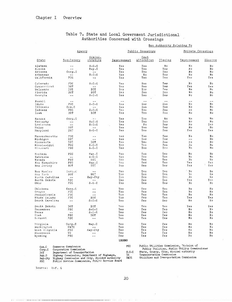
Chapter I Overview
Table 7. State and Local Government JurisdictionalAuthorities Concerned with Crossings
R. e A“t hori tx_E$&s21cK_!2.__ —--------
Private Cr.. si.g*
s-c-cHWY.C
S.i:c.-
PucDOT
DOT
DOT--
s-c-c
D;;DOT
s-c-c
Pi;
Corn. c
PscDOT
Idaho
Illinois
Indiana
10”.
Corp. c----
DOT
DOT
s-c-cs-c-c
Maryland
Massachusetts Puc
DOT
DOTPSc
no--No
NoNo
--
D;;s-c-c
s-c-c
Hi.h,i8..Minnesotab!i.sissippiMi,s”uri Psc
M<,,, t,,”. Psc Hvv. C
NsbraskaNevada
New Ham”shireDOT
C“FP. CDO’r
--,5,,,: Y<,, k
+I”rt,lt Ca,”li”aNorth Dakota
Ohio
Psc
Puc
Corp. cOregon PucPe”nsyl. ani. PUC
Rhofie Island PUCSouth Carolina
--.---
DOT
s-c-c
South Dakota
T,,>” ..,..T,,,.,
Utah
DOT
Psc
Pi;Psc
DOT
s-c-cs-c-c
DOT
Ye,
No
!:No. .
Corp. cu&Tc
PscTC
Psc
Yes
Yes
No
NoN.
NoNo
-.Hwy-cty Yes
Yes----
commerceCommission PVC
Corporation Commission
Department of Tra..portation s-c-c
Highway Commia, ion, Department of EighmYs, TC
Hi~h”.yG...i..i.”andCity,divided.“th.rit~DaTGpublicS.=,i..C...iss”,”,PublicS.r.i..Boud
PublicUtilities Commission, Divisiofi ofPublic Utilities, P“blic Utility Commissioner
State, ComtY, City, divided authority
Traneport.tie” Com.i..io”utilities and Trensport.tion C...iss”.”
Con.cCorp. cDOT
Hw. C
::-ctY
SOUrCe: Itef. 6
20
Chapter I Overview
AARIn the area of crossings, the
works closely with the U.S. DOT,the U.S. Congress, NTSB, the Ne[tionalSafety COuncil (NSC), the RailwayProgress Institute (RPI) and others.
The AAR has crossing representat-ives in each State. These Staterepresentatives, who are railrc,adem-ployees, provide liaison with groupsand government agencies having inter-ests in crossings within that State.They hold meetings when deemed neces-sary to ensure that a cooperative ap-proach is established and maintained.
The AAR provides some of thefinancial support for the NationalOperation Lifesaver progrm and worksclosely with the NSC in promoting thecontinued development of this pro-gra.
The AAR conducts research per-taining to crossings. Some of thisresearch is conducted jointly withother organizations~ e.g. AASHTO andthe U.S. DOT. Recent research hasincluded a cOmpilatiOn of State lawsand regulations pertaining to cross-ings and a review of the “tilizatiOnof train-borne traffic warnin,g de-vices. The AAR cooperates with OtherOrganizations conducting resear,?h byproviding infomat ion on crossingsfrom the railroad perspective.
The American Railway EngineeringAssociation (AREA), an organizationof railway engineers and off:Lcers,and having a close relationship withAAR, serves to advance bowledgf? per-taining to the scientific and e(!onom-ic location, construction, and main-tenance of railways. It has 22 tech-nical comittees that develop factsand infowation pertaining to theirscientific and technical int<?restsand develop recommended practicf?sforadoption in the Manual for Rz~ilwayEngineering and Portfolio of Track-
work P:lans. Comittee g, ~ighway
Railway PrOgrms, is charged withmatters pertaining to railroad-high-way grade crossings.
Th<>American Short Line RailroadAssociation (ASLRA) is a non-profitorganization representing the inter-ests of fts member railroads. Itprovides liaison between its membersand other groups having interests inthe railroad industry. The ASL8Aworks l~iththe U.S. DOT and the U.S.Congress to ensure that the uniquecharacteristics of small railroadsare cO~sldered in national legisla-tions an,d regulations.
The Railway Progress Iostitute(BPI) is an organization of railroadequipment suppliers. It se:rves asliaison on the national level betweenits members and those agencies andorganizations having interest:~in therailroad indust~.
The RPI monitors the developmentof national policies and progl?amsanddetemines the:~rimpact on its mem-bers. It identifies the futlire de-mand for its members’ products andidentifies areas of needed ?roductdevelopment and research.
Each of its members is continu-ally conducting in-house research Fortine purpose Of improving existingproducts and developing new productsto meet :railroadneeds. Improvementsfn the crossing area involve constantwarni~ ‘timedevices, Crossirlg sur-faces~ a]tdmodifications to aL1tomatic’traffic control devices. RPI is afinancial supporter of OperationLifesave;?and a collabOratOr ~,iththeNational Safety Co~lncil.
The American Association ofState }Iighway and TransportationOfficials (AASHTO) Ss an organizationof officials from State highway agen-
Chapter I Overview
eies. AASHTO seeks to foster thedevelopment of a national transporta-tion system and serves as liaison be-tween its members and other agenciesand organizations having interests inhighway transportation.
AASHTO devslops and publishesrecommended standards for the design,operation and maintenance of high-ways, including crossings. It con-ducts research as appropriate andparticipated with the AAR in thedevelopment of information pertainingto rail-highway related matters.
The Transportation ResearchBoard (TRB) was established in 1920and operates mder the corporateauthority of the National ResearthCouncil, which serves both theNational Academy of Sciences and theNational Academy of Engineering. Thepurpose of TRB is to advance knowl-edge of the nature and performance oftransportation systems through thestimulation of research and dissemi-nation of information. The TRB1sobjectives are accomplished ‘throughtechnical committee activities,amual meetings, seminars and work-shops, computerized information ser-vices, publications, and specialprojects.
TRB Committee A3A05, RailrOad-Highway Grade Crossings, promotescrossing research and sponsors tech-nical papers for publication and pre-sentation at the TRB Amual Meeting.It identifies areas of needed re-search and publishes a bibliographyof past crossing research and othersubstantive documents in the generalarea of railroad-highway grade cross-ings.
The National Safety COucil(NSC) was established in 1913 andchartered by Congress as a not-for-profit voluntary service organization
solely committed to preventing acci-dents and occupational illnesses.The NSC coordinates the NationalOperation Lifesaver Program. The NSCworks with State agencies to encour-age the development and promotion ofOperation Lifesaver programs withineach State. It sponsors nationalconferences for the purpose of shar-ing mique Operation Lifesaver prO-grams and for identifying solutionsto existing impediments. The NSC de-velops Operation Lifesaver materialsand guides for use in individualState programs.
The American Road and Transpor-tation Builders Association (ARTBA)is an organization whose members in-clude representatives of the railroadindustry, public officials at alllevels of government, business firmsin the traffic safety industry, andhighway contractors. For many years,ARTBA has supported programs of Fed-eral assistance for safety improve-ments at grade crossings.
American Trucking Associations,In.. (ATA) is the national organiza-tion of trucking industry management.It represents all segments of theindustry and deals with all phases ofthe industry1s operations.
Safety has the highest priority.As a part of its overall safety ef-fort, the ATA’s Safety Departmentdevelops material to inform manage-ment and drivers of grade crossinghazards and the safe practices neces-sary to avoid accidents. The depart-ment has developed a grade crossingevaluation program for use by membersof its safety arm, the ATA Council ofSafety Supervisors, at the State andnational level.
The Institute of TransportationEngineers (ITE) is a professionalscientific society of transportation
Chapter I Overview
professionals responsible for plan-ning, design, operations, and Inainte-nance of surface transportatit>n fa-cilities. The ITE has more th:~n7000members in over 70 countries. Themajority of its members are ijlvolvedin highway and public transportation.Many Institute members, emplo!~ed bygovernment agencies, industrj,, andconsulting firms, work direct;Lywithrailroad - highway grade cl,ossingissues and problems.
D. Some General Legal Co~ider<~tions-Railroad-Highway Grade Cros:;~s
Highway and railroad en~~ineersare becoming increasingly involved ina field of litigation that WZLS re-cently of concern only to attc>rneys.Today, it f.sincumbent upon stzlffsofState highway departments, localtransportation agencies, and rail-roads to become aware and keepabreast of highway law in gener,alandthe legal elements Of oPer~,tionalpractices in particular. This dis-cussion of legal considerattc,ns inthe administration and management ofrailroad-highwaygrade crossings is avery basic discussion of a very com-plex subject. It is not meant tointerpret the law or establish guide-lines. It is intended only to alerttransportation agencies and railroadsof the need to recognize and respondto the possible consequences of fail-ure to maintain and safeguard therailroad-highway wade crossing. Theparticular aspects of a specificpotential legal problem should bediscussed with an attorney.
Until recently, govermnent enti-ties were generally immune from law-suits on the theory of 11sovereignimmunity” derived from English commonlaw. Under the sovereign immunitydoctrine, a government entity can besued only if it consents to the suit
in advance. Over the past 25 yearsthis situation has changed dramat-ically. SOvere~.gn imun~.ty k~as beeneroded through the actions c~fcourtsand/or legislatures and now survives
in less than a third of the States.Consequ{sntly, mny State highway de-partments have become vulnerable tolawsuit:s for damages resulting fromhighway accidents.
Since many States now may besued for negligence on the part ofits officers or employees, new empha-sis ha!s been placed upon the legalrespons:Lbilityof parties involved inthe se:LectiOnand implementation ofcrossing safety .~provements. Thisis especially true when the State isrespons:Lble for determining whichcrossin[$s are to be upgraded and thetype of warning systernsto be in-stalled,,
The State has a duty to correcta dangerous condition when its agencyhas act,ual or “constmcttve!f nottceof the hazards. The sctual noticerequirement does not apply when thedangerous condition is the res,~ltofthe State’s own negligence. For ex-ample, a State is not required tohave ac!tual notice of faulty cOn-structicjn, maintenance, or repair ofits highways, because the State isexpecteclto know of its own actions,i.e. “constructive!? nottce. ,,con-structive” notice is howle dge im-puted by law, usually after a.ninjuryhas occu[rred. However, if the dangerdid not arise as a consequence of ac-tive negligence (such as faulty con-Stmction ), the agency has tl~e duty
to make repairs once it has actualnotice of the defect.
Most courts hold that the Statemust have had notice of the d,:fectorhazard for a sufficient or reasonabletime ,,t~afford them a reasonable op-portunity to repair the cond?tton or
23
Chapter I Overview
take precautions against the danger.”Statutes may require that States havenotfce of the condition for a speci-fied period of time. If, for exam-ple, the notice period is five days,and an accident was caused by a de-fect that originated early in the dayof the accident, the statutory noticeperiod would not be satisfied and theagency would not have had a reasona-ble opportunity to effect repairs.On the other hand, the notice may besatisfied where the condition has ex-isted for such a time and is of sucha nature that the State should havediscovered the condition by reasona-ble diligence, particularly wherethere is no statutory specified time.In such instances, the notice is saidto be constmctive, and the State’sknowledge of the condition is said tobe tiplied. In deciding whether theState had notice, the courts mayconsider whether the defect was la-tent and difficult to discover. Thatis, the court will consider the na-ture of the defect, its location andduration, the extent and use of thehighway, and whether the defect couldbe readily and instantly perceived.Routine inspection and correctionprocedures are important in light ofthe trend by courts to pemit lessand less time before findi~ “con-structive notice”.
To wderstand the legal respon-sibilities of traffic agencies andrailroads, it is necassary to wder-stand the basic principles and termi-nology of tort law.
A tort in legal terminology is acivil wrong other than breach of con-tract, for which a court of law willprovide a remedy in the fom of anaction for money daages. There arethree basic elements involved in anytort action:
0a legal duty exists between theparties;
o a violation or breach of that dutyby one of the parties; and,
o daage to the other party as aproximate result of the breach ofduty.
Torts can be either intentional(e.g., assault, and battery, falseimprisonment, trespass, and theft) orunintentional (e.g., negligence).The primry concern for crossings areallegations of negligence.
Liability for a tort means thelegal obligation to pay money damagesto the person injured or dmaged.More than one person or organizationmay be liable for dmages arising outof the same incident. In the case Ofnegligent conduct by an employee,both the employee and the employermy be liable.
Negligence can be defined as thefailure to do something that a “rea-sonable person” would ordinarily do,or the doing of some~ning that a rea-sonably prudent person would not do.Negligent conduct is that which cre-ates an unreasonable risk for othersto whom is owed a duty of exercisingcare.
The reasonable person is a cri-teria used to set the standard ofcare in judging conduct. In effect,this test of negligence representsthe ,,failure to use OrdinarY care,”and is most often used in determiningliability. In the context of thisHandbook, engineers may be fomd tobe negltgent if their conduct doesnot measure up to that of a hypothe-tical reasonable, prudent, and care-ful engineer mder similar circu-mstances.
24
Chapter I Overview
Contributory negligence refersto cOnduct that falls below thestandard of care that a persOn
is legally require~e.g.a driver) toexercise for his own safety, and thisfailure is a contributing cause tothe injury or daage he has suffered.Until recently, in most States, afinding of contributory negligence bythe court would bar a plaintiff fromrecovering dmages even if the de-fendant’s negligence had been estab-lished and was the primary cause ofthe accident. Contributory negli-gence as a bar to recovery is beinggradually eroded in the U.S. by thedoctrine of “comparative negligence!!.
Comparative negligence is a ruleof law adopted by mny States wherebythe negligence of both part~es iscompared, and recovery is pe:mitteddespite the contributory negligenceOf the plaintiff. However, plain-tiff’s d~ages are usually decreasedin proportion to his own contr:Lbutorynegligence.
Duty in tort law is an <obliga-tion requiring persons to confom toa certain standard of conduct for theprotection of others against mrea-sonable risks. Negligence is abreach of duty to exercise rea:;Onablecare owed to those persons tn whomthe duty applies. In this context, ahighway department owes a duty to alltravelers on the highway tO avOidcreating unreasonable risks fo~,thosetravelers, and to meet the standardof care imposed upon that depa?.tment.
The standard of care may be es-tablished by a multitude of f:lctors.As a minimm, all persons are re-quired to avoid the creation c)f un-reasonable risks, where feasible. Inaddition, statutes and regulationsgovernfng conduct are also com~,onentsof the standard of care by whic!hcon-duct is judged.
Ftially, and perhaps most impor-tantly, the accepted standards andpractices of a profession, :Lrade,orindustry define the standard Of careby which conduct is judged. Includedin the definition of ‘!acceptedstand-ards and practices!lis the Manual onUnifO~ Traffic Control De;~icesand——-other similar standards. The Ameri-can Railway Engineering Associationpromulgates technology pertaining torailroads in its Manual of RailwayEnginee~.
——This is not a stand-
ard, however, but a wans oj;provid-ing railroad engtieers with guide-lines for the construction of rail-roads.
To place tbe above concepts inperspective, it is necessary to rec-
ognize the following characteristicsof tort liability.
o Negligence is the failure to usereasonable care.
o Court decisiom in tort c].aimsarebasei on the concept of the exis-tenCe of a ‘treasonable person!!exercising “ordinary care”, i.e.“reasonable care“ mder the sameor similar circumstances whichwould be exercised by a pmdentperson.
o The three elements necessary inever:ytort elafm are:
- existence of legal duty owed bythe defendant to the plaintiff;
- a breach of that duty; and,
- the occurrence of dm,age Orinjury which is the reasonablyforeseeable result cf thatbreach of duty.
In effect, this means that theplaintiff (the one bringtng thesuit), if he is to win a jud~ent in
Chapter I Overview
a basic highway negligence case, mustprova the following.
o The defendant (agency)had a legalduty to use reasonable care to-wards the plaintiff (the injuredparty).
o The defendant breached that duty,(fell below the standard of carethus comitting an act of negli-gence).
o The dmages (tnjuries, prOPertYdamage, pain and suffering, 10ssof income, etc.) suffered by theplaintiff were caused by thebreach (defendant’s negligence),and were the foreseeable result ofthat breach. That is, but for thedefendant’s negligence, the plain-tiff “ould not have suffered da-ages.
o Finally, depending on whether theState follows the “contributory”or ,,comparative,,negligence doc-trine, the plaintiff, in order torecover all of the dmages suf-fered, must not have contributedto that negligence (“contributory”negligence), or must have beenless at fault than the agency
(“comparative”negligence).
To understand the concept oflegal duty, it is necessary to recog-nize the distinctions between discre-tionary acts and ministerial (nondis-cretionary) acts. Many States thatno longer retain their sovereignimunity have enacted a Tort ClaimsAct. This Act prescr?-besthe condf.-tions ~der which the State, theiragencies, and their employees may beheld accountable. Most of theseinclude a limited exemption frombility for negligence in the per-formance (or in the nonperformance)of so-called discretionary aCtiVi-t~es.
The tem “discretiomry” refersto the power and duty to make an in-formed choice among alternatives. Itrequires consideration of these al-ternatf.vesand the exercise of inde-pendent and professional judgment inarriving at a decision or in choosinga coursa of action. On the otherhand, ministerial duties ?nvolveclearly defined tasks perfomed withlninim~ leeway as to parsonal judg-ment and not requiri~ any evaluatingor weighing of alternatives. Conse-quently, they are nondiscretionary.
In modern law, the dtst%ncttonsbetween discretf.onaryand Lninisterialfunctions are of great importance injudging tort claims Sgainst govern-mental entities. In general, a pub-lic Organization or its employees arenot l!.ablefor negligence in the per-formance of discretionary activities.However, the courts are constantlyrevising the law in these areas, andthe classification of a particulargovernmental activity as ef.ther dis-cretionary or ministerial is subjectto shift!ng legal titerpretations.
It should be recognized that thelim;.tedexemption from liability thathas been afforded to discretionaryactivities in no way providas abso-lute protection from legal liabf.lity.If discretion is abused or exercisedrecklessly or unjustly, courts mymove in and substitute their own dis-cretion for that of the agency.
The courts are fairly unifom inholdfng that the design of highwaysis a discretionary fmcti.on becauseit involves high - level planningactfv:-ty and evaluation of policies,alternatives, and other factors.This is supported by court decisionswhich hold that design funCtiOnS arequasi-legislat~.vein character andmust be protected from second-guess-ing by the courts who are inexpert at
26
making such decisions. Design i~un-ity ~tatutes represent a fu~ther ef-fort by legislatures to immunize gov-ernmental bodfes and employees fromliability arising out of negligenceor errors tn a plan or design dulyapproved under current standards ofreasonable safety.
The courts consider two factorsin determining whether a State hastaken reasonable care in giving thepublic adequate warning at a rail-road-highway grade crossing. Thesefactors can be stated in the follow-ing mnner.
o In light of the history of acci-dents and/or level of traffic atthe particular crossing, was anaccident reasonably foreseeable?If S0,
o Was the State reasonable in itschoice of warning devices to alertthe public of the foreseeablerisk?
Liability for accidents occur-ring at grade crossings is governedby the law of negligence. The lawimposes upon states and railroads theduty to exercise reasonable care toavoid injury to persons using thehighway. States and railroads areunder no duty to provide absolutesafety.
Potential liability in crossingaccidents may create a reluctance onthe part of States, railroads, andsuppliers, to initiate new technologyor procedures that may lead to charg-es of negligence. Experimentalionand in-service trials of new devicesis restricted by both potential liti-gation and the contractual, insur-ance requirements and negotiationthat are involved.
Chapter I Overview
The scheduling of improvementprojects has become a significantissue in,recent court cases involvingcrossing accidents. The applicationof administrative rules and proce-dures to ensure the expeditious in-stallation of safety improvementsbased upon the principal of the alle-viation of the highest potential haz-ard is a.major factor In these cases.
It shOuld be ObviOus that it iSmore 10gical to expend public fundsin sound management practices and inproper highway maintenance than inthe settlement of claims or in pay-ment of adverse judgments. Conse-quently, it would seem appropriate toreview maintenance activities andreporting procedures to limit expO-sure to tort liability. It wouldalso seem helpful to assure that allagency employees involved in such ac-tivities are well informed of the le-gal implications of their functions.
It has been suggested that agen-cies and railroads could significant-ly reduce tort liability suits in-volving traffic control devices byimplemer[tingfour basic principles.
0
0
0
0
E.
Know the laws relating to trsfficcontrol devices
Condu\ct and maintain an inventoryof devices
Replace devices at the end oftheir effective lives
Apply approved traffic control de-vice specifications and standards
References
1. Accident/Incident Bulletin, Wash-ington, DC: Fe{eral Railroad Admin-istration, published annually.
Chapter I Overview
2. Alternative Solutions to Railroad 12. RailrOad Faet~, Washington, DC:Impacts on Communities, Final Report, Association of American Railroads,Minnesota Department of Transporta- September 1983 and October lg84.tion and North Dakota State HighwayDepartment, December 1981. 13. Railroad-HighwaySafety, Part I:
A Comprehensive Statement of the3. Amos, Charles L., ‘tRailroadCross- Problem, A Report to Congress, Wash-ings‘v, Better Roads, Vol. 49, No. 9, ington, DC: U.S. Department of Trans-September 1979, No. 10, October 1979. portation, November 1971.
4. Annual Report on Highway SafetyImprovement Programs, Washington, DC:Federal Highway Administration,published annually.
5. Federal-Aid Highway Program Manu-~, Washington, DC: Federal HighwayAfiinistration, updated periodically.
6. Federal Highway AtiinistratSonSurvey of Region and Division Of-fices, unpublished, 1984.
7. Gertler, Judith B., A Study ofState Programs for Rail-Highway GradeCrossing Improvements, Washington,DC: Federal Railroad Administration.
14. Railroad-HtghwaySafety, Part II:Recommendations for Resolving theProblem, A Report to Congress, Wash-ington, DC: U.S. Department of Trans-portation, August lg72.
15. Report on the Unit Coal TrainComunity Impact Conference, Washing-ton, DC: U.S. Department of Trans-portation, August 1979.
16. Schercinger, John M., ‘t1g84 GradeCrossing Statistics Show ContinuedSafety Improvement”, Washington, DC:Assocl.ation of American Railroads,September lg84.
Report FRA-oPPD-78-7, June lg78. “ 17. Schoppert, David W. and Dan W.Hoyt, Factors Influencing Safety at
8. Highway Statistics, Washington, Highway-Rail Grade Crossings, Wash-DC: Federal Highway Administration, ington, DC: Highway Research Board.published annually. NC~RP Report 50~ lg~8.
g. ‘!Maintenance Cost Study of Rail- 18. Traffic Control Devices Handbook,road-Highway Grade Crossing Warni~ Washington, DC: Federal HighwaySystemsqf, Association of American Administration, 1983.Railroads, October 1982.
10. Prevention of Rail-Highway GradeCrossing Accidents Involving RailwayTrains and Motor Vehicles, Washing-ton, DC: Interstate Comerce Comis-sion, November lg62.
11. Rail-Highway Crossing Accident/Incident and Inventory Bulletin,Washington, DC: Federal RailroadAtiini~tra~ion, published annually,
2a
II. COWONRNTS OF A RAILROAD-HIGWAY GRADE CROSSING
A railroad-highway grade cross-ing Uy be viewed as simply a specialtype of highway intersection, in thatVne three basic elements of highwaysare present: the driver, the vehi-cle, and the physical intersection.As with a highway intersection, driv-ers must appropriately yield theright - of - way to opposing traffic;but unlike highway intersections, theopposing trsffic, trains, only rarelymust yield Yne right-of-way to themotorist. Drivers of motor vehicleshave the flexibility of alteringtheir path of travel and can altertheir speed within a short distance.Locomotive engtieers, on the otherhand, are restricted to moving theirtrains down a fixed path and changesin speed can only be accomplishedmuch more slowly. Because of this,motorists bear most of the responsi-bility for avoiding collisions withtrains. In effect, the “RailroadCrossing,,cro~ab~ck is a “Yield” sign
and motorists have an obligation toso interpret it. Traffic and highwayengineers can assist motorists intheir task by providi~ them withproper highway design and trafficcontrol devices.
Tbe components of a railroad-highway grade crossi~ are dividedinto two categories: highway andrailroad. The highway component isfurther classified into four ele-ments: driver, vehicle, roadmy, andpedestrians. The railroad componentIs classified tito train and trackelements. The location where thesetwo components intersect must be de-signed to incorporate the basic needsof both highway vehicles and trains.
Traffic control devices are uti-lized to provide the motorist withinformation concerning the crossing.
Typically, an advance warning signand pavement markings inform the mo-torist that a crossing lies ahead inthe travel path. The crossing itselfis identified through the use of thecrossbuek. These traffic control de-vices, advance warning sign, pavementmarktngs, and crosshuck, are temed“passive” because their message re-mins constant with time.
,,A=t~vett traffic ~ont~~l devices
tell the motorist whether or not atrain is approaching or occupying thecrossing and thus give a variablemessage. Typical active traffic con-trol devices are flashing lights andautomatic gates.
The U.S. DOT/AAR National Rail-Highway Crossing Inventory providesinformation on the number of publiccrossi~s having each type of trafficcontrol device as shown in Table 8.
A. The l[~hway Component
1. Driver
The driver is a key component ofthe railroad-highway grade crossiwscene and is responsible for obeyingtrafftc control devices, trafficlaws, and the rules of the road.Highway and railroad engineers, whoplan and design initial installationsand later improvements of railroad-highway grade crossings, should beaware of the several characteristics,capabilities, requirements, needs,and obligations of Vne driver. Thisinformation wil1 help them, throughthe proper engineering design ofcrossing installation and improve-ments, to asaist drivers in meeti~their responsibilities.
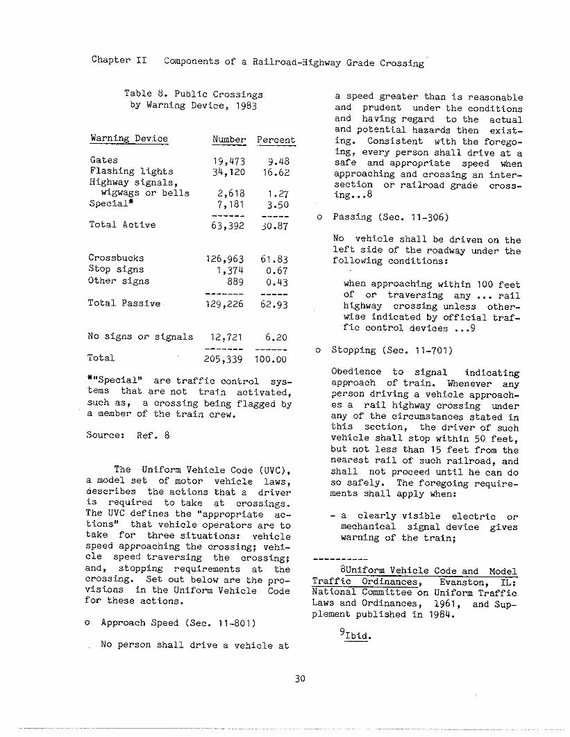
Chapter II Components of a Railroad-HighwayGrade Crossing
Table 8. Public Crossings
by warning Device, 1983
Warning Device
GatesFlashing lightsHighway signals,wigwags or bells
Special*
Total Active
CrossbucksStOp signsOther signs
Total Passive
No signs or signals
Total
Number
19,47334,120
2,6187,181
------63,392
126,9631,374883
-------129,226
12,721-------
205,339
Percent——
9.4816.62
1.273.50-----30.87
61.830.670.43-----62.g3
6.20------100.00
*“Speeial~i are traffic control sys-tems that are not train activated,such as, a crossing being flagged bya member of the train crew.
.Source: Ref. 8
The Unifora Vehicle Code (UVC),a model set of motor vehicle laws,describes the actions that a driveris required to take at crossings.The UVC defines the “appropriate ac-tions” that vehicle operators are totake for three situations: vehiclespeed approaching the crossing; vehi-cle speed traversing the crossing;and, stopping requirements at thecrossing. Set out below are the pro-visions in the Uniform Vehicle Codefor these actions.
0 Approach Speed (Sec. 11-801)
No person shall drive a vehicle at
0
0
a speed greater than is re~onableand prudent under the conditionsand having regard to the actualand potential hazards then exist-ing. Consistent with the forego-ing, every person shall drive at asafe and appropriate speed when
approaching and crossing an inter-section or railroad grade cross-ing...a
Passing (Sec. 11-306)
No vehi.eleshall be driven on theleft side of the roadway ~der thefollowing conditions:
when approaching within 100 feetOf or traversing any ... railhighway crossing unless other-wise indicated by official traf-fic control devices ...9
Stopping (Sec. 11-701)
Obedience to signal indicatingapproach of train. Whenever anyperson driving a vehicle apprOa~h-es a rail highway crossing mderany of the circumstances stated inthis section, the driver of suchvehicle shall stop within 50 feet,but not less than 15 feet from thenearest rail of such railroad, andshall not proceed until he can doso safely. The foregoing require-ments shall apply when:
-a clearly visible electric ormechanical signal device giveswarning of the train;
----------8Uniform Vehicle Code and Model
Traffic Ordinances, Evanston, IL:National Comittee on Unifom TrafficLaws and Ordinance,plement published in
‘Ibid.
30
1961, and Sup-1984.
Chapter II Components of a Railroad-HighwayGrade Crossing
-a crossj.ng gate is lowered orwhen a human flagman gives orconttnues to give a signal ofthe approach or passage of arailroad train;
-a railroad train approachingwithin approxi!mtely 1,500 feetof the highway crossing emits as~.gnal audible from such dis-tance and such railroad train,by reason of its speed or near-ness to such crossing, is animmediate hazard; and,
- an approachi~ railroad trainis plainly visible and is inhazardous prOXimity tO suchcrossing.10
The UVC also prohibits any vehi-cle from driving around or under anygate or barrier while it is closed orwhile it is being opened or closed(Sec. 11-701b).
Each State has its own regula-tions that may vary from those above.More information on State laws andregulations affectim crossings areco~tained in a Comp~lation of-StateLaws and Regulations on Matters,AffectingRail-Highway Crossings.
The situations faced by a driverof any vehicle at a crossing occursin three areas or zones. These zonesare adapted from the informationhandling zones defined in A User’sGuide to Positive Guidance. Infoma-~n handling zones are particularareas of road that correspond to sec-tions of highway on which driversshould ideally make certain decisionsconcerning the upcoming crossing.The three zones are described belowand shown in Table 9.
----------
l“Ibid.——
Approach Zone -- Tllis zone isthe a“~a in which drivers begin toformula:~e actions needed tO avOidcolliding with trains. Drivers usethis zone to search for a train orsignal, to recognize any hazards, andto decide on the proper course ofaction. The approach zone precedesthe non]?ecovery zone.
Within the approach zone, thevehicle operator must become awarethat a crossing is ahead. Inform-ation is usuaily provided by an ad-vance warning sign and, in some cas-es, by pavement mrkings. In virtu-ally all situations, the driver musttake notice through visual observa-tion of the crossing itself, its as-sociated control devices, and sOme-times through the sound of the trainhorn.
The advance warning should beplaced at a distance in advance ofthe crossing such that the driver isprovided sufficient time to alter ve-hicle speed and take tne appropriateaction. It is incmbent upon thedriver to heed the advance warningand to operate the vehicle such thatthe driver can respond properly tOthe conditions ahead. Sign placementdistances for advance warning signsare discussed in Chapter IV, Identi-fication of Alternatives.
Nonrecovery Zone -- The nonre-covery zone begins at the point alongthe road where drivers must make astop decision if a train is approach-ing or occupying a crossing. Theore-tically, if the stop/go decision isdelayed beyond the beginning of thenonrecovery zone, the amowt of high-way remaining will be insufficient toavoid a collision. The nonrecoveryzone ends at the beginning of thehazard zone. It starts at the stop-ping sight distance point required bythe vehicle speed. Stopping sight
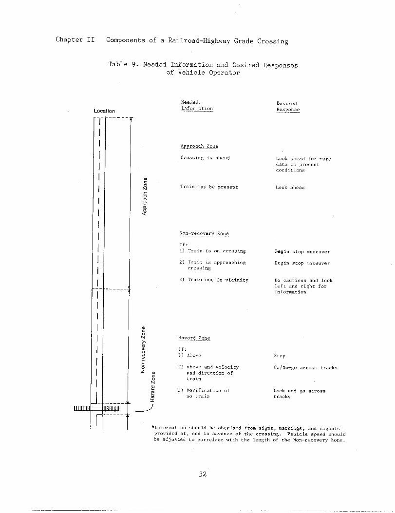
Chapter II Components of a Railroad-HighwayGrade Crossing
‘Ta.ole9. Needed I!lforma-Lio~zand 2esired ReSpO:ISeSof Vehicle Opsrator
Location
Needed Desiredl“f<, r~ .R&s&o>~
m
I
II
III
I
I
I
i
IIII
----m
APProa cl, z“”.
Cr.ssi”g i. akead L.,,kaheadFo.....dataO“p,ese”~.“”di~i.”s
If:
1) Train is on crossing Begin stop ma”e””er
3) Troi” not i“ “ici”ity Be ca”tio”s a“d l“ok
left a“d right for
i“f”r”atiom
Ilazaxd zone
If:
1) ab””e
2) abc,.e and velocity
and direction of
tra, n
3) Verification of
“o train
stop
Co/No-go across tracks
L“ok and go across
tracks
*Information should be obtained from signs , markings, a“d signals
pr.”ided at , a“d i“ ad” . . . . “f tke crossing. Vehicle speed sh”.ld
be adj”ste. d c“ c“rre late with che length of the No”-recovery Zone.
32

Chapter II Components of a Railroad-HighwayGrade Crossing
distances are discussed in ChapterIV, Identification of Alternatives.
The proper design and installa-tion of traffic control devices willprovide the majority of drivers withthe information needed to make thedecision to stop, if necessary. Atcrossings with passive traffic con-trol devices, the motorist is prO-vided with a view of the crossbuckthat, by its design, infO~s the mo-torist of the location of the cross-ing and requires, as a regulato~y de-vice, that the motorist approach thecrossing at a speed such that thevehicle can be stopped safely if atrain is approaching or occupying thecrossing. Having been provided thisinformation, the motorist must oper-ate the vehicle as required by theprevalent conditions, e.g. visibilityof an approaching train. Thus, if adriver’s view of an approaching trainis restricted, e.g. due to sightobstructions, inclement weather, ordarkness, the driver should reducevehicle speed so that, if necessary,it can be stopped.
Active traffic control devicesare designed to assist the driver inmaking the appropriate stop/go deci-sion. Active traffic control devicesare activated by an approaching trainand thus provide this information tOthe motorist who is then required bylaw to stop in advance of the cross-tng. Ideally, all crossings wouldhave active traffic control devices;however, the cost to install andmaintain them at the 205,000 publicat-grade crossings is prohibitive.Thus, active traffic control devicesare placed at those crossings consid-ered to be nore hazardous than oth-ers.
Hazard Zone -- The hazard zoneis the rectangle formed by the widthof the highway and a distance meas-
ured along the highway on either sideof the tl”acks. This zone is the areawhere stopped or approaching rotorvehicles can collide with approach-ing or stopped trains. This zone canbe considered as being 15 feet eitherside of the closest and farthestrail.
In this final zone, the objec-tive is for the mtorist to cross thetracks safely. At crossings withpassive control devices, the pmdentdriver has heeded the advance warningand the crossbuck and has deteminedif a train is occupying or approach-ing the crossing. The driver thenbrings the vehicle to a stop short ofthe hazard zone. At crossings withactive traffic control devices, thepmdent driver has heeded the acti-vated device and brings the vehicleto a stop short of the hazard zone.
Once stoDoed. a driver must not‘.. ,
cross the tracks mtil a decision hasbeen made that it is safe to dO S0.This action is dictated by law orregulation.
and operation of agrade crossing must
2. Vehicle
The designrailroad-highwaytake into consideration the varietyof vehj.cles that are 1ikely to trav-erse the crosstig. In this regard,crossings are exposed to the fullarray of vehicle types found on thehighway,,from motorcycles to tractor-trailer trucks. These vehicles havewidely different characteristics thatwill directly influence the designelements of the crossing. Equallyimportant is the cargo these vehiclescarry, especially children in schoolbuses and hazardous materials intrucks.
Table 10 shows the nmber, type,and percentage of rotor vehicle acci-

Chapter II Components of a Railroad-HighwayGrade Cross~ng
Table 10. Motor Vehicle Accidents and Casualtiesat Public Crossings by Vehicle Type, 1983
Total AccidentsNuberRate*Percent
Total FatalitiesNmberRate*Percent
Total InjuriesNmberRate*Percent
Vehicle miles oftravel (billions)
Registered vehicles
Accidents permfllfon vehicles
Automobiles
4,2733.5068.13
3150.2665.22
1,6031.31
67.58
1,221.85
Buses
111.630.17
00.000.00
355.181.47
6.75
Trucks
1,9454.7631.01
1510.3731.26
7171.76
30.23
408.51
123,169,738 555,819 35,197,962
34.69 19.79 55.26
Motorcycles Total
43 6,2723.58 ---0.69 100.0
17 4831.U2 ---
3.52 100.0
1‘1 23721.40 ---
0.72 100.0
12.00 1,649.11
5,736,001 164,659,520
7.50 ---
*Rate is the nmber of accidents, fatalities or injuries divided by billionsof vehicle miles traveled.
Source: Ref. 8
dents by vehicle type ~.nvolvingtrains at crossings during 1983. Thedata provides some indication of therelative hazard for each of the vehi-cleS. Trucks have the highest over-all accident rate, t.e. nmber ofaccidents per number of vehicle milestraveled on all highways.
Motorcycle accidents have ahigher fatality rate, probably be-cause of the lack of operator protec-tion provided by the vehicle. Buses,trucks and motorcycles all have high-er injury rates than automobiles.The relatively high injury rate for
buses can be attributed to the highnmber of passengers typically fomdin buses. Of the 11 bus accidentsoccurring in 1983, five involvedschool buses.
Several physical and petiomancecharacteristics of vehicles itiluencethe safety of vehicles at crossings.These include vehicle dimensions,braking performance, and accelerationperformance.
Vehicle Dimensions. The lengthOf a vehicle has a direct bearing Ontbe inherent safety of a vehicle at a
34
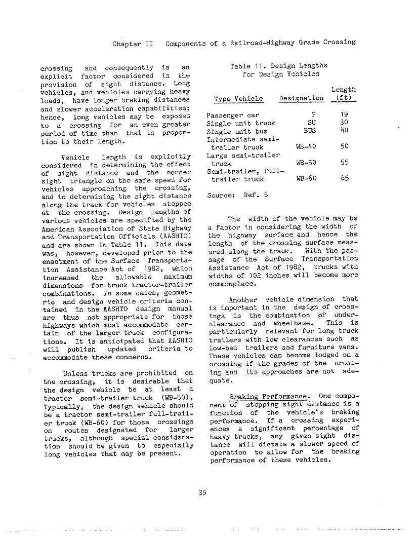
Chapter II Components of a
crossing and consequently is anex?licit factor conside~ed in theprovision of sight distance. Lo~gvehicles, and vehicles car~ing heavyloads, have longer braking distancesand slower acceleration capabilities;hence, long vehicles may be exposedto a crOssing fOr an even greaterperiod of time than that in propor-tion to their length.
Vehicle length is explicitlyconsidered in determining the effectof sig’ht distance and the cOrnepsight triangle on the safe speed forvehicles approaching the crossing,and in determining the sight distancealong the track for vehj.cles stoppedat the crossing. Design lengths ofvarious vehicles are specified by theAmerican Association of State Highwayaad Transportation Officials (AASHTO)and are shown in Table 11. This datawas, however, developed prior to theenactment of the Surface Transporta-tion Assistance Act of 1982, whichincreased the allowable maxi.mmdimensions for truck tractor-trailerCombinations. In some cases, geomet-ric and design vehicle criteria con-tained in the AASdTO design mnualare thus not appropriate for thosehighways which must accomoaate cer-tain of the larger truck configura-tions. It is anticipated that AASHTOWill publish updated criteria toaccommodate these concerns.
Unless trucks are prohibited onthe crossing, it is desirable thatthe design vehicle be at least atractor semi-trailer truck (~-50).Typically, the design vehicle shouldbe a tractor semi-trailer full-trail-er truck (~-60) for those crossingson routes desIgnated for largertrucks, although special considera-tion should be given to especiallylong vehicles that may be present.
Railroad-HighwayGrade Crossing
Table 11. Design Lengthsfor Design Vehicles
Type Vehicle_.—
Passenger carSingle u!nittruckSingle u~nitbusIntermediate sai-trailer truck ~-l~o 50
Lengtn(ft)Designatio~
P 19Su 30BUS 40
Large semi-trailertruck m-50 55
Semi-trailer, f~lll-trailer truck ~-60 65
Source: Ref. 6
The width of the vehicle may bea factor in considering the width ofthe highway surface and hence thelength of the crossing surface meas-ured along the track. With the pas-sage oj?the Surface TransportationAssistal~ce Act of 1982, trucks withwidths of 102 inches till become morecommonplace.
Another vehicle dimension thatis important in the design of cross-ings is the combination of under-clearanlte and wheelbase. This isparticularly relevant for long trucktrailers with low clearances such aslow-bed trailers and furniture vans.These vehicles can become lodged on acrossing if the grades of the cross-ing and its approaches are not ade-quate.
Braking Performance. One compo-nent of stopping sight distance is afunction of the vehicle’s brakingperforunce. If a crossing experi-ences a significant percentage ofheavy trucks, any given sight dis-tance will dictate a slower speed ofoperation to allow for the braki~performance of these vehicles.
Chapter II Components of a Railroad-HighwayGrade Crossing
Acceleration Performance..- Ac-celeration of vehicles is ixnportantto enable a stopped vehicle to accel-erate and clear the crossing before atrain that was just out-of-sight, orjust beyond the train detection cir-CUitry, reaches the crossing. Largetrucks that have relatively poor ac-
celePatlOn capabilities, coupled ,xiththeir long lengths, make them partic-ularly hazardous in this type of sit-
uation.
There are three phases of opera-tion for a truck that has stopped ata crossing:
0 start-up whel?the cllltchi.s beingengaged;
0 acceleration from the point offull clutch engagement; and,
0 COntinued travel until the cross-ing is cleared.
Another aspect of the accelera-tion performance of vehicles atcrossings is the design of tinecross-f.ngand the condition of the crossingsurface. Crossings and approachesthat are on a steep rise are dfl,ffi-clultand time consming to cross.Also, vehicles will move SIOWer over
crossings that have rough surfaces.
Special Vehicles. Three vehj.cletypes‘are of particular concern forcrossing safety: e) trucks car~inghazardous materials; b) vehj.clescar-rYing Passengers for hire; and, c)school buses. Accidents involvingthese vehicles can result in numerousinjuries and/or fatalities, perhapsin catastrophic proportions if cer-tain hazardous cargoes are involved.
In a special study condticted bythe National Transportation SafetyBoard (NTSB), it was determined thatan average of 62 accidents involving
train collisions l~ithtrucks trans-porting hazardous materials occurannually. Their exainat ion of theaccident data revealed that theseaccidents tend to occur near truckteminals.
Provis~.onsto enhance safety forthese special Vehicles are furtherdiscussed in Chapter IX, SpecialIssues.
3. Roadway
A major component of the cross-ing consists of the physj.cal aspectsof the highway on the approach and atthe crossing itself. The followi~roadway characteristicsare relevantto the design and control of rail-road-highway grade crossings.
0
0
0
0
0
0
0
Location -- urban, rural
Type of road -- arterial, COIIec-tor, local
Trafftc volme
Geometric features -- number oflanes, horizontal and verticalaligment, sight distance, cross-ing angle, etc.
Crossfig surface and elevation
Nearby intersecting highways
Illumination
These elements will be discussedbriefly in this Chapter and in detailin subsequent Chapters.
Location and Type of Road. Fig-ures 3 and 4 show the accidents perCrossing per year for Ig83 as a func -
tiOn of type of road for the urbanand rural system. Roads are classi-fied by function, from interstate tolocal roads. Crosstigs designated as
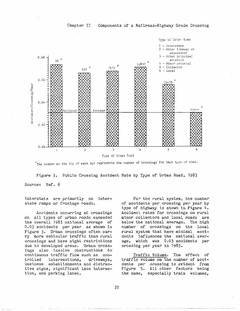
Chapter 11
“o’: 95*
Components of a Railroad-HighwayGrade Crossing
Pjpe 0: u,’,,. ?Oad
; - I“t, rstate2 - Otherfreeway“r
expressway3 - Otherprincipal
arterial,, .,.
1
.Then..berat
Figure 3.
Source: Ref. 8
i]lterstate are
2 3 h 5 6
T;fpeofUrban8.0.6
the top of each bar represents the numberof.ro.singsf.?thattype.fr.aa.
Public Crossing Accident Rate by Type of Urban Road, 1983
pr?.marily on inter-state rwps or frontage roads.
Accidents occurring at crossingson all types of urban roads exceededthe overall 1983 national average of0.03 accidents per year as shown inFigure 3. Urban crossings often car-ry more vehicular traffic than ruralcrossings and have sight restrictionsdue to developed areas. Urban cross-i.n~s also involve obstructions tocontinuous traffic flow such as con-trolled <intersections, driveways,business establishments and distrac-tive signs, significant lane interac-tion, and parking lanes.
Fe)?the rural system, the numberof accidents per crossing per year bytype of highway is shown in Figure 4.Accident rates for crossings on ruralminor collectors and local roads arebelow the national average. The highnmber of crossings on the localrwal system that have minimal acci-dents influences the national aver-age, which was 0.03 accidents percrossing per year in 1g83.
Traffic Volue. The effect oftraffic volume on the number of acci-dents per crossing is evident fromFigure 5. All other factors beingthe same, especially train volmes,
37

Chapter II Components of a Railroad-HighwayGrade Crossing
20“0.10
0.08II
0.02
0.00
Typ.Ofisu~.1RO.C1 - T“terscate2 - Other principal
arterial
3- Minor arterial
4 - Xajor C“llect”r
5 - >lin”rC“llect”r6 - Local
1 2 3 4 5 6
TYP~OfH.ralRoad
*Then“.berat ths top of each bar represents the number of crossings for that type of road.
Figure 4. Public Crossing Accident
Source: Ref. 8
accident frequency increases with in-creasing traffic volume. However,traffic vollme alone is not a suffi-cient forecaster of accidents atcrossings, as demonstrated by acci-dent prediction models, that are dis-cussed in Chapter III, Assessment ofCrossing Safety and Operation.
Geometric Features. The geomet-ric design features that can affectsafety at railroad - highway gradecrossings Include the following.
0000
Nwber of lanes and pavement l~idthHorizontal and vertical aligmentCrossing angleCrOasing elevation
Rate by Type of Rural Road, 1983
These features, in turn, affect sightdistance to, and at crossings.
Nuber of Lanes. Only a smallportion, 6$, of crossings are onhighways with more than two lanes.It is not bown how ~ny crossi~swith two lanes have an approach widthgreater than two lanes. The reduc-tion of lane width at a crossing canaffect vehicle-vehicleaccidents aswell as accidents with trains.
At two lane crossings, a pulloutlane may be provided for tmcks orbuses that are required to stop atthe crossing. By providing a pullout
38
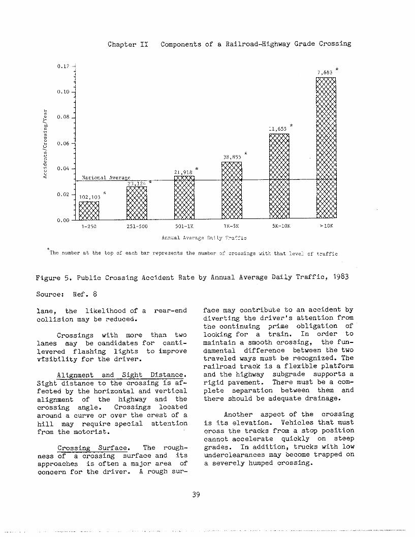
Chapter II Components of a Railroad-HighwayGrade Crossing
7,683*
11,655*
38.855* M
. . .1-250 251-500 501-lK lK-5K 5K-10K >10K
Ar>nualA.,erageDailyTraf:ic
Thenumberatthetopofeachbarrepresentsthe““mberofcrossing.withthatlevelofr,r.ffi.
Figure 5. Public Crossing Accident Rate by Annual Average Daily Traffie, 1983
Source: Ref. 8
lane, the likelihood of a rear-endcollision may be reduced.
Crossings with more than twolanes may be candidates for canti-levered flashing lights to improvevisibility for the driver.
Aligment and Sight Distance.Sight distance to the crossing is af-fected by the horizontal and verticalalignment of the highway and thecrossing angle. Crossings locatedaround a curve or over the crest of ahill may require special attentionfrom the motorist.
Crossing Surface. The rough-ness of a crossing surface and itsapproaches is often a major area ofconcern for the driver. A rough Sur-
face may contribute to an accident bydiverting the driver’s attentfon fromthe continuing prime obligation oflooking for a train. In order tomaintain a smooth crosstig, the fun-damental difference between the twotraveled ways must be recognized. Therailroad track is a flexible platfomand the highway subgrade supports arigid pavement. There must be a com-plete separation between them andthere should be adequate drainage.
Another aspect of the crossingis its elevation. Vehicles that mustcross the tracks from a stop positioncannot accelerate quickly on steepgrades. In addition, trucks with lowuderclearances may become trapped ona severely hmped crosstig.

Chapter II Components of a Railroad-HighwayGrade Crossing
Intersecting Highways. Approxi-mately 36% ~f~~oad-highwaygrade crossings have a highway inter-section within 75 feet. Frequently,roads parallel tracks and intersect-ing roads als[>intersect the railroadI-esulting in s crossing near thehighway Intersection.
The higher occurrence of acci-dents at these crossings is in partdue to a short stora2e area for vehi-cles waiting to move through theintersection after passin2 over thecrossing. If the intersection issignalized, or if the approach fromtinecrossing is controlled by a stopsign, then queues may develop to thecrossing, leaving a vehicle “trapped’!on the crossing. Also there are moredistractions to the mOtOrist and Inorevehicle-vehicle conflicts.
Crossings within a close dis-tance to a signalized or stop-con-trolled Intersection should be care-fully evaluated for proper controls.The critical distance is a functionof the number of vehicles expected tobe stopped by the intersection con-trol.
Illumination. Illuinination ofthe crossing c= definitely aid themotorist. In 1983, 2,582, of 6,272total crossing accidents, occurreddurin2 darkness. Illumination may beeffective in redlucingaccidents atnight. The U.S. DOT / AAR NationalRail-Hi2hway Crossing Inventory re-ports that commercial power is avail-able at over 90% of public crossings.Therefore, lightin2 is feasible atmost crossings, depending, of course,on t}le reliability of the powersource. Design details on illumina-tion are discussed in Chapter IV,Identification of Alternatives.
4. Pedestrian
In 1983, accidents involving pe-destrians at crossin2s accounted foronly 1%, 68, of all crossing acci-dents. As can be expected, theseaccidents almost always result in aninjury or fatality. In fact, in 1983there were 37 pedestrian fatalities,6.8% of all crossing fatalities.Tnese statistics do not includepedestrian accidents occurring else-where along railroad tracks. Exclud-ing accidents and incidents at cross-ings, 400 trespasser fatalitiesoccurred on railroad property during1983. This represents 37% of allrailroad related fatalities.
There are several types of pre-ventive measures that might be em-ployed. The list includes:
o fencing or other devices for en-closing rights-of-way;
o grade separations;
0 additional signing;
0 safety education; and,
0 surveillance and enforcement.
These measures are discussed in moredetail in Chapter IX, Special Issues.
B. Railroad C-ponents
Railroad companies are classi-fied by the Interstate Commerce Com-mission (ICC) on the basis of grossrevenue. Effective Janua~ 1, 1982,the ICC adopted a procedure to adjustthe Class I threshold for ifilationby restating current revenues in 1g78constant dollars. A Class I railroadcompany has an annual gross operatingrevenue In excess of $50 million in1978 dollars which equates to about
40

Chapter”II Components of a Railroad-Highway Grade Crossing
$83.5 million in 1983 dollars. AClass II railroad has an annual grossoperating revenue of between $10 and$50 million in 1978 dollars. ClassIII railroads include all switchingand terminal companies and all rail-roads with annual gross operatingrevenues of less than $10 million in1978 dollars. In 1983, there were 27Class I and 18 Class II railroads inoperation as shorn in Appendix C.
In 1983, there were about 270Class III line-haul railroads andabout 142 switching and terminal com-panies, also Class III. Many ofthese Class 111 railroads provideswitthing and terminal services forthe larger Class I and II railroadcompanies. Some Class III railroadstake over the operation of a singleline that a larger railroad abandonedfor economic reasons. Class IIIrailroads often require assistancewith regard to railroad-highway gradecrossings because of their limitedmanpower and financial resources.These small railroads are often un-able to seek out Federal and Statefunds for improving crossings, yetsafety at their crossings is just asimportant as at any other crossing.
For the purposes of this hand-book, the railroad components ofrailroad-highway grade crossings havebeen divided into two categories,train and track, as discussed below.
l.-
During every business day, ap-proximately 100,000 freight cars areloaded in the United States, Canada,and Mexico. Statistics as to the av-erage length, net lading, and overallspeed of freight trains in a typicalyear do not begin to describe the va-riety of operations involved in rail-road freight movements. Unit trainsmay cover over 1,500 miles without a
change of consist and gross from6,500 tO 13,500 tons, while a car ina local freight may move only a cou-ple of miles and represent the entiretrain consist. Dedicated piggybacktrains may be limited to 25 to 50cars, and run over several railroadswith fe%,, if any, intermediate stopsto set out and pick up blocks of carsat major terminals. This variationin rail movements occurs also on themicrosca.le, i.e. at individual rail-road-highway grade crossings. Thus,the design of traffic control systemsat crossings must allow for a widevariation in train length, trainspeed> and train occurrence.
Long trains, e.g. unit trains,directly affect the operation ofhighway traffic over crossings andindirectly affect safety as well.Unit trains consist of as many as 100freight cars with the same lading.Coal and grain are two major commodi-ties that are transported in unittrains. Because of their lengths,unit t]:ainswill take longer to passover a crossing and, in effect, closethe crossing to highway traffic for alonger period of time. In addition,some commwities have passed ordi-nances restricting train speed forthe purpose of improving safety.However, this practice directly re-duces the level of service for high-way traffic and may also affect safe-ty. Because of the longer period oftime during which the crossing isclosed to highway traffic, a motoristmay take risks by passing over thecrossing just ahead of a train. Inmany cases, risks such as these arenot successful and collisions re-sult.
Trains other than mit trainstypically consist of a variety Ofcars and ladings. A few cars may bepicked up along the way and may bedropped off from the same train or
41
Chapter II Components of a Railroad-HighwayGrade Crossing
may be taken to a railroad yard where
a new train is made up of cars withsimilar destinations. It is obviousthat trains must stop to pick upcars, but it is unfortunate that some
Of these pick-up points are locatedin the central portion of communi-ties. ,Thisresults in trains movingslowly over the crossing, or evenstanding on the crossing as the pick-up is made. With the lengths offreight trains today, an entire com-munity can be physically divided by afreight train stopped on all of itscrossings.
Railroads have operating proce-dures designed to prevent extensiveblockage of crossings and many Stateshave passed regulations prohibitingVne blockage of crossings for variouslengths of time. Twenty-nine Statesexpressly prohibit trains from block-i!lgcrossings for a period that var-ies from 5 to 15 minutes. Of these,16 States exempt moving trains. Afreight train can be divided to allowhighway traffic to pass through, butthis practice requires the braking
system to be filled with air, whf.chcan take considerable time. Changesin operating practices that mayassist in the alleviation of thesetypes of problems are discussed fur-ther in Chapter IV, Identification ofAlternatives.
Railroads carry passengers inaddition to freight although thismode of transportation has declinedduring recent decades due to con-struction of the interstate highwaysystem, the convenience of the auto-mobile, and the speed of the air-plane. Amtrak, the National RailroadPassenger Corporation, provtdes pas-senger service nationwide. Thisrailroad, created by Congress in1971, operates over track owned byitself (primarily in the Northeast)and over track owned by other rail-
road companies. In accordance withlabor agreements, employees of pri-vately owned railroad companies oper-ate Amtrak passenger trains over thatrailroad’s trackage. Some privaterailroad companies continue to oper-ate passenger trains particularly forcommuter service in urban areas.Some municipal, regional, and Stateauthorities have taken over railroadcommuter services. Many light-railtransit companies are in operationand being constructed in this countrywith rlumerouscrossings and 10ngitu-dinal street use. (These are notnormally considered as railroads .intabulating crossing accidents). Onthe heavy rail rapid transit systems,there are few crossings of publichighways at-grade.
X.ocomotives and cars obviouslyform a train, but for crossing pur-poses any rail operation over a high-way is of concern, whether it is oneor more engtnes or a group of carspushed over a crossing. Most locomo-tives today are diesel-electric orstraight electric although some rail-roads operate stem locomotives asspecial passenger trains for histori-cal purposes. In 1983, there were25,838 10cOmOtive units in service on
Class I railroads, all but 63 of theunits were diesel-electric.
All locomotives are equippedwith headlights that are illuminatedwhenever the locomotive is in motion.One type of light is a 30 volt, 200.~attPAR-56 sealed bea lamp with anoutput of 200,000 to 300,000 candle-power. Tbe lamp is usually used inpairs. Some railroads use oscillat-ing headlights, comprised of one ormore standard locomotive headlightlamps on a mounting plate that ismoved by a small mntor in a figureeight, circular, or oval pattern.The light beam thus “sweeps” acrossthe tracks.
Chapter II Componen-tsof a Railroad-Highway Grade Crossing
Several different types of rooflights are sometimes used on locomo-tives to serve as markers illyards sothat the locomotive can be easilylocated among numerous freight cars.These types of roof lights includebeacon lights* strobe lights, andsequentially flashing lights. In aneffort to make the locomotive as vis-ible as possible; some railroads uti-lize these types of lights at rail-road-highway grade crossings~ eitherilluminating them whenever the loco-motive is in motion or illuminatingthem in advance of crossings. TheFederal Railroad Administration (FRA)considered a regulation that wouldrequire the mandatory use of strobelights or, in a later proposed rule-making, the use of any of the fourtypes of roof lights at crossings.However, based on information re-ceived in response to the proposedrulemakings and on an indepth analy-sis of costs and benefits~ the FRAconcluded that “...the information inthe Docket does not support the prop-osition that alerting lights areeffective in reducing the incidenceof grade crossing accidents. Withoutthat support a Federal regulatory re-quirement that railroads equip theirlocomotives with an alerting light isnot justified’!.1’1
Locomotives are also equippedwith air powered horns that are usedto sound a warning of a train’s ap-proach to a crossing and are used forvarious other signals in railroad op-erations. The FRA requires the hornto produce a minimum sound level of96db(A) at 100 feet forward of the
1lllDisplayof Altering Lights byLocomotives at Public Rail-HighwayCrossings: Termination of Rule Mak-ing,‘f Docket No. RSGC-2, Notice 4,Federal Register, Vol. 48, No. 88,Washington, DC: May 5, 1983.
locomotive. The locomotive enginee:rsowds the horn in advance of :>crossing in a sequence of two longblasts, followed by a short blast,then followed by one long blast. Th?point of initiation of the whistle i;~indicated by a whistle post locatedalongside of the tracks. Many Stateshave laws pertaining to the Iocatiomwhere the horn must be blom. Ninet-een States specify 80 rods (1/,Lmile), but 14 others specify varyingdistances ranging from 300 to 1,80,3feet.
Some local agencies have passedordinances prohibiting the soundin,gof the whistle in certain areas tolessen the environmental noise im-pact. This is not generally recom-mended because the train whistle pro-vides warning to a motorist or pedes-trian that a train is approaching thscrossing. Even at crossings withactive traffic control systems, thetrain whistle provides a redundantindication that affects the hearingof a highway user while the trafficcontrol device affects sight.
In 1983, there were 1,542,278freight cars in service. The majori-ty of these were box cars, hoppers,and covered hoppers as shown in Table12. In addition, there were 2,61Dpassenger-train cars,in service in1983, not including those owned bycommuter authorities which do notreport to the Interstate CommerceCommission. The majority of freightcars have a capacity of 70 or 100tons; however, 125 ton cars are usei
track rated to support them.
:R ~terchangeOver 1 car size is standardized byregulations. A car
10.08 feet wide by 15.08 feet highcan go an~here. Some cars may be ashigh as 17.08 feet. Overall car bodylength.is limited to 89 feet, or 95feet including the couplers.
Chapter II Components of a Railroad-HighwayGrade Crossing
Table 12. Types
Type
Box Cars:
of Freight Equipment
Number
Plain boxEquipped box
Covered hoppersFlat carsRefrigerator carsGondolasHoppersTankOther
Total
17a,465157,291303,172142,29163,705171,554315,ao5la3,73026,265
I,542,27a
Source: Ref. 9
Railroad freight cars are notilluminated and the installation ofreflectorized markers on freight carshas been studied for some time. Themost recent study found that the ra-pid accumulation of dirt necessitates
frequent cleaning of the reflectors,
which represents more than half ofthe total cost of freight car reflec-torization. In this study, testswere conducted on the Canadian rail-road systea, where reflectors havebean installed on freight cars since1959, and on the Boston and MaineRailroad that installed high intensi-ty retroreflectors for the purposesof the study. Reflector reflectiveintensity was found to be reduced to23% of its initial value after sixmonths in service. After one and twoyears in service, reflective intensi-ty degraded to 14 and 5%, respective-ly, of its initi.alvalue. This deg-~adation of reflective i.ntensttyre-sults in the reflector providing lit-tle to no improvement in visibilityof freight cars at crossings.
Primarily because of their enor-mous weight, railroad trains are slowto accelerate and decelerate. Nurner-
ous factors affect a traints acceler-ation capability such as the numberof locomotive units, the horse~werrating of each unit and, of course,the number and weight of freightcars. At low speeds, a commutertrain may accelerate at 1.5 mph persecond while a fast freight mayaccelerate at O.3 mph per second. Asspeed increases, the accelerationrate decreases, a freight with 4.0 hpper ton can accelerate at only aboutO.1 mph per second at 70 mph.
The br~ing system used ontrains is the air brake that providesadequate uninterrupted pressure frolncar to car. The single air hose atthe end of each car is manually con-nected to its neighbor and then thebrake system is charged. When brak-i~ is required, the pressure in thebrake pipe leading back through thetrain is reduced. This causes thevalve on each car to use air from theauxiliary reservoir to build up pres-sure in the brake cylinder, thus ap-plying the brakes. For an emergencyapplication, the brake valve openstine brake pipe to atmospheric pres-sure and the resulting rapid rate ofbrake pipe pressure reduction causesthe car valves to dmp the contentsof both auxiliary and emergency res-
ervoirs j.ntothe brake cylinder.
Braking distances are dependenton mny factors that vary for eachtrain, e.g. nmbe r and horsepowerrating of locomotives, number andweight of cars, adhesion of wheels onrails, speed, and grade. Tnerefore,the braking distance of a train cannot be stated exactly. An estimateis that a typical 100 car freighttrain traveling 60 mph would requireover one mile to stop in emergencybraking.
Table 13 shows that the majorityof crossings have rail traffic con-
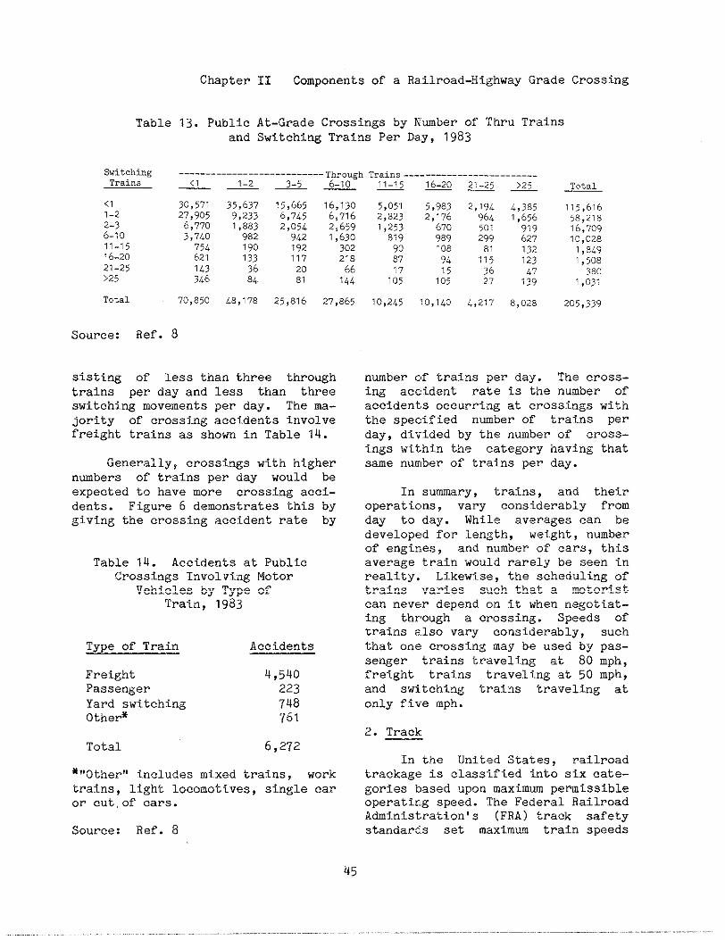
Chapter
Table 13. Publicand
SwitchingTr.i”,
<11-22-36.1011-1516-2021-25>25
Total
II Components of a Railroad-HighwayGrade Crossing
At-Grade Crossings by Nmber of Thru TrainsSwitching Trains Per Day, 1983
Source: Ref. 8
30,57127,9056,7703,74075462114>346
70,850
35,b3?9,2331,8839821901333684
48,178
15,6656,7452,0549421921172081
25,816
16,13ob,7?62,659?,63030221866144
27,865
sisting of less than three throughtrains per day and less than threeswitching movements per day. Tbe ma-jority of crossing accidents involvefreight trains as shown in Table 14.
Generally, crossings with highernwbers of trains per day would beexpected to have more crossing acci-dents. Figure 6 demonstrates thisgiving the crossing accident rate
Table 14. Accidents at PublicCrossings Involvi~lgMotor
Vehicles by Type ofTrain, 1983
Type of Train Accidents
Freight Q,540Passenger 223Yard switching 74aOther* 761
Total 6,272
byby
~,,other!iincludes mixed trains, worktrains, light locomotives, single caror cut,of cars.
Source: Ref. a
5,0512,8231,2538199087
lH
?0,245
5,9832,17b67o9891089415105
30,140
2,194964501299811353627
4,217
4,3851,b5b
“919
627
6,028
335,6?658,2?816,709?0,0281,8L93,508380
7,03?
205,339
number of trains per day. The cross-ing accident rate is the number ofaccidents occurring at crossings withthe specified nmber of trains perday, divided by the number of cross-ings within the category having thatsame number of trains per day.
In summary, trains, and theiroperations, vary cons iderably fromday to day. While averages can bedeveloped for length, weight, numberof engines, and number of cars, thisaverage train would rarely be seen inreality. Likewise, the scheduling oftrains varies such that a motoristcan never depend on it when negotiat-ing through a crossing. Speeds oftrains also vary considerably, suchthat one crossing may be used by pas-senger trains traveling at ao mph,freight trains traveling at 50 mph,and switching trains traveling atonly five mph.
2. Track
In the United States, railroadtrackage is classified into six cate-gories based upon maximum permissibleoperating speed. The Federal RailroadAdministration’s (FRA) track safetystandards set maximm train speeds
45
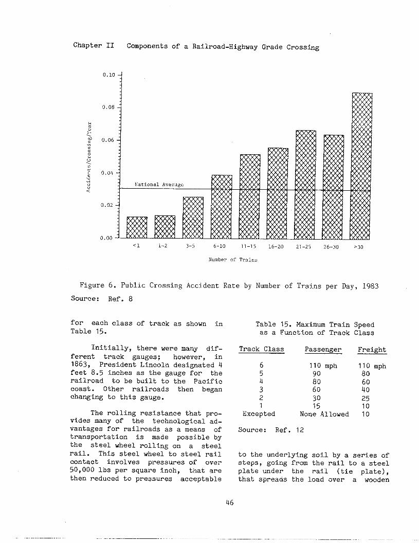
Chapter II Components of a Railroad-HighwayGrade Crosstig
0.10
0.08
/> 0.06~
0.00
m
<1 1-2 3-5 6-10 11-15 16-20 21-25 26-:)0 >30
Numberof Train.
Figure 6. Public Crossing Accident Rate by Number of Trains per Day, 1983
Source: Ref. 8
for each class of track as shown inTable 15.
Initially, there were many dif-ferent track gauges; however, in1863, President Lincoln designated 4feet 8.5 inches as the gauge for therailroad to be built to the Pacificcoast. Other railroads then beganchanging to thj.s gauge.
The rolling resistance that pro-vides many of the technological ad-vantages for railroads as a means oftransportation is made possible bythe steel wheel rolling on a steelrail. This steel wheel to steel railcontact involves pressures of over50,000 lbs per square inch, that arethen reduced to pressures acceptable
Table 15. Maximum Train SDeedas a Function of Track Class
Track Class Passenger
6 110 mph5Q ::3 602 301 15
Excepted None Allowed
Freight
110 mph806040251010
Source: Ref. 12
to the underlying soil by a series ofsteps, going from the rail to a steelplate under the rail (tie plate),that spreads the load over a wooden
46
Chapter 11 Components of a 13allroad-HighwayGrade Crossing
tie, that spreads the load over rockor slag ballast, that spreads theload to a sub-ballast (usually grav-el, cinders, or sand), that spreadsthe load to the subgrade consistingof either the native soil below orsome superior material obtained offsite.
Rail is rolled from high qualitysteel and that being rolled todayweighs from 115 to 140 lbs. per yardand is six to eight inches high. Forthe last 50 years the standard raillength has been 39 feet for transpor-tation in 40 foot cars. In track,these rails are held together bybolted joint bars or are welded endto end in long strings. Boltedjoints are, however, less rigid thanthe rest of the rail so that the railends wear more rapidly. COntinuouslywelded rail is often used today, par-ticularly on main line tracks. Railis welded into lengths of about 1,500feet and taken to the point of in-stallation. The remaining joints canbe eliminated by field welding in-place.
The steel rails are spiked toties that are typically msde of woodwith preservative impregnated to pre-vent decay. The ties hold the railsto gauge, support the rail, distrib-ute the load to the ballast, and pro-vide flexibility to cushion impactsof the wheels on the rail. Pre-st.ressedconcrete ties have come intogreater use on American railroads inrecent years, but still represent un-der 1% of the ties in use in the U.S.
Spikes or otinerrail fastenersare used to connect the rail to theties for the primary purpose Of Pre-venting the rail from shffting side-ways. Since rail has a tendency tomove lengthwise, rail anchors areused, particularly on heavy-dutytrack.
Ballast.is used to hold the tiesin place, to prevent lateral deflec-.ti0n9, and to spread out the loadthat averages about 100 pst justwderneath the tie. Ballast must bc?able to resist degradation from theeffects of tie motion that generat.c:“fines” that may “cement” into azlimpervious mass. Ballast must alsoprovide good drainage that is espe-.cfally Important for the strength ofthe subgrade, and also prevents mudfrom working its way up to contmi-.nate the ballast.
Railway track is normally main-.tained by sophisticated high produc-.tion mechanized equipment. Track:surface is maintained by tamping ma-.chines that raise the track and corn-.pact the ballast waler the tieg. Inthis process it is often necessary toraise the track a few inches, and the>best f~rack stability will occw ifthis raise can conttnue through the?crossing area instead of leaving aldip in the track. Lowering track isa very costly operation and can leaclto subgrade instability problems.
Tl”ack components are generallyreplaced as needed. A typical heavy-.duty freight llne on tangent may bcisurfaced every two years, have about.25% of its ties renewed every eightyears, and have its rail changed eve-.ry ’12years.
Similar to htghways, railroadtrack is classified intO several cat-.egories dependent on its utilizatiorlfn t.e]%s of traffic flow. Mairltracks are used for through trairlmovements between and through sta-.t.iOns and terminals. Branch linetrackage typically carries freightfrom its origin to the main line oriwhich it moves to its destination oz-to another branch line to its desti..nation,, Passing tracks, sometimescalled sidings, are used for meeting!
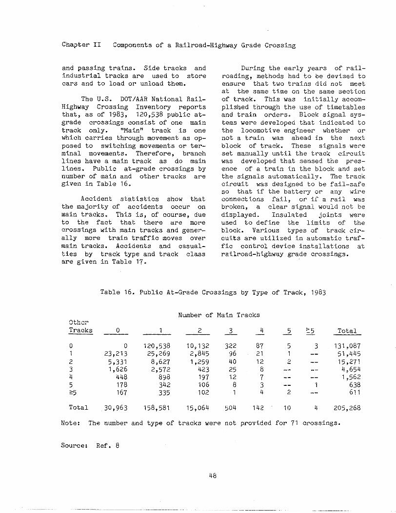
Chapter II Components of a Railroad-Highway
and passing trains. Side tracks andindustrial tracks are used to storecars and to load or unload then.
The U.S. DOT/AAR National Rail-Highway Crosstig Inventory reportsthat, as of 1983, 120,538 public at-grade crossings consist of one maintrack only. “Main” track is onewhich carries through movement as op-posed to switching movements or ter-minal movements. Therefore, branchlines have a main track as do mainlines. Public at-grade crossings bynmber of main and other tracks aregiven in Table 16.
Accident statistics show thatthe majority of accidents occur onmain tracks. This is, of course, dueto the fact that there are mrecrossings with main tracks and gener-ally more train traffic moves overmain tracks. Accidents and casual-ties by track type and track classare given in Table 17.
Grade Crossing
During the early years of rail-roading, methods had to be devised toensure that two trains did not meetat the same time on the same sectionof track. This was initially accom-plished through the use of timetablesand train orders. Block signal sys-tems were developed that indicated tothe locomotive engtieer whether ornot a train was ahead i.n the nextblock of track. These signals wereset manually until the track circuitwas developed that sensed the pres-ence of a train illthe block and setthe signals automatically. Tne trackcircuit was designed to be fail-safeso tinatif the battery or any wireconnections fail, or if a rail wasbroken, a clear signal wo,~ldnot bedisplayed. Insulated joints wereused to define the limits of theblock. Various types of track cir-cuits are utilized j.na,~tomatictraf-fic control device installations atrailroad-highway grade crossings.
Table 16. Public At-Grade Crossings by Type of Track, 1983
Nmber of Main TracksOtherTracks o 1 2 ~ ~ ~ > Total—. _ _
o 0 120,538 10,132 322 a7 5 3 131,oa71 23,213 25,269 2,845 96 21 1 -- 51,4452 5,331 8,627 1,259 40 12 ~ -_
315,271
1,626 2,572 423 25 8 -- --
44,654
448 89a 197 12 7 -- --
5 1781,562
342 106 a 3 -- 1 63825 167 335 102 1 4 ~ -- 611
Total 30,963 15a,581 15,064 5~4 142 10 4 205,26a
Note: The number and type of tracks were not provided for 71 crossings.
Source: Ref. a

Chapter II Components of a Railroad-Highway Grade Crosstig
Table 17. Accidents and Casualties at Public Crossings InvolviwMotor Vehicles by Track Type and Track Class, 1983
Track Class*
&
1,382219590
5---2
4------
10---
3
2---
1
1,403219596
&
932633
---------
1------
---------
---------
942633
6— Unknown Total
5,480473
2,~a2
416295
123---24
24Ua67
9---4
6,2724a3
2,372
Track Type
MainAccidentsKilledInjuries
YardAccidentsKilledInjuries
1 2
1,3604a529
69---25
22---8
29---
5
1------
1,4814a567
~
I,74a159758
20---11
7---
1
11------
2---2
1,7aa159772
a23la
236
3---1
71335
27a244
44---13
---------
Sidi~AccidentsKilledInjuries
79---
15
10------
---------
IndustryAccidentsKilledInjuries
1745oa
20311
---------
UnknownAccidentKilledInjuries
1---
---
3---
1
---
------
TotalAccidentsKilledInjuries
1,35525343
3---
1
14a660
*See Table 15 for a definition of Track Class
Source: Ref. 8
C. R=EREWCRS
1. Accident/Incident Bulletin, Wash- Simons - Boar&an Publishing Corp.,ington, DC: Federal Railroad Atiin- lga2.istration, published annually.
3. Code of Federal Regulations, Title2. Amstrong, John H., The Railroad - ~, Washington, DC: General ServicesWhat It Is, What It Does, Omaha, NE: A*inistration, published annually.
49
Chapter II
u. “DisplayLocomotivesCrossings”,
Components of a Railroad-HighwayGrade Crossing
of Alerting Lights by 12. Traffic Control Devices Handbookat Public Rail-Highway Washington, DC: Federal Highway Ad-Teminiation of Rule mak- ministration, 1983.
ing, D6ck:t No. RSGC-2. NotIce 4.Fe~&ral Register, Vol. 48, No. 88, 13. Unifom Vehicle Code and ModelWashington, DC: May 5, 1983. Traffic Ordinance, National C~ittee
on Unifom Traffic Laws and Ordi-5. Poage, J.L., J.C. Pomfret, and nances, 405 Church Street, P.O. BoxJ.B. Hopkins, Freight Car Reflectori- 1409, Evanston, Illinois 60204, 1961zation, Washington, DC: Federal Rail- and Supplement published in lg84.road Atiinistration, Report FRA-RRS-83-1, December lg82.
6. A Policy on Geometric Design ofHighway and Streets, Washington, DC:herican Association of State High-way and Transportation Officiais,lg84.
7. Post, T.J., G.J. Alexander, and H.Lunenfeld, A User’s Guide to PositiveGuidance, Second editfon, Washington,DC: Federal Highway Atiinistration,Report FHWA-TO-81-1, December, 1981.
8. Rail-Highway Crossing Accident/In-cident and Inventory Bulletin, Wash-ington, DC: Federal Railroad Atiin-istratiOn, published annually.
9. Railroad Facts, Washington, DC:Association of American Railroads,October 1984.
10. Railroad/Highway Grade CrossingAccidents Involving Trucks Transport-ing Bulk Hazardous Materials, A Spe-cial Study, Washington, DC: NationalTransportation Safety Board, ReportNTSB-HZM-81-2, September 1981.
11. Russell, Eugene, R., BeverlyNarm, Charles L. Amos, and John M.Schercinger, COmpilatIon of StateLaws and Regulations on Matters Af-fecting Rail-Highway Crossings, Wash-ington, DC: Federal Railroad Atiinls-tration, Report FHWA-TS-83-203, April1983.
50

III. A8SESSWNT OF CROSSING SAFNTY AND OPERATION
The Federal Highway Administra-tion (FHWA) requires each State todevelop and implement a highway safe-ty tiprovement program that consistsof three components: planni~, imple-mentation, and evaluation. The proc-ess for improving safety and opera-tions at railroad - highway gradecrossings consists of the same threecomponents and may be considered apart of a State’s highway safetyimprovement program.
FHWA policy and procedures for ahighway safety improvement programare contained in the Federal - AidHighway Program Manual, Volme 8,ChaDter 2, Section 3 (FHPM 8-2-3).The objective of a highway safetyimprovement program is to reduca ‘fthenumber and severity of accidents“ anddecreaae “the potential for accidentson all highways”.
FHPM 8-2-3 requires the planningcomponent to consist of:
0
0
0
a process for collecting a~ldmain-taining a record of accident,traffic, and highway data, includ-ing, for railroad - highway gradecrossings, the characteristics ofboth highway and train traffic;
a process for analyzing availabledata to identify highway loca-tions, sactions, and elements de-temined to be hazardous on thebasis of accident experience oraccident potential;
a process for conducting angtieer-ing studies of hazardous loca-tions, sections, and elements todevelop highway safety improvementprojects; and,
0 a process for establishing priorit-ies for implementing highwa:{safety improvement projects.
The implementalion componentconsists of a process for programmiw~and implementing safety improvements.The evaluation com~nent consists Ora process for determining the effec’tthat safety improvements have i]treducing the number and severity OFaccidents and potential accidents.
This section of the Railroad-Highway Grade Crossing Handbook pro-vides guidance for tha planning comp-onent consisting of the collectio]~and maintenance of data, the analysisof data, and engineering studies. I!~addition, the “systems approach”, amethod by which several crossings arestudied collectively, is discussed.Chapter IV identifies the variouscrossing improvements that are availa-ble. Chapter V presents guidelinesfor selecting improvements based Onsafety and operational effectivenessand costs. Chapter VI provides guide-lines for the implementation compo-nent of the safety program and Chap-ter VIII addrasses the evaluationcomponent.
A. Collection and Wintenace of Datm
A systematic method of identify-ing problem locations is most impor-tant. For railroad - highway gradecrossings two types of informationare needed: invento~ and accidentdata. Inventory data includes thelocation of the crossing, volmes ofhighway and train traffic over thecrossing, and Ag~~n:ld~~am~:sea;:the crossing. .crossing are also neaded.
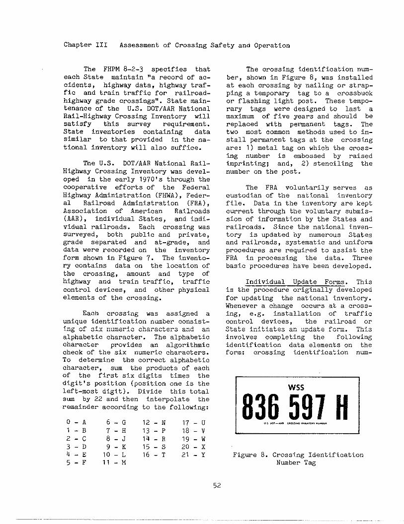
Chapter III Assessment of Crossing Safety and Operation
The FHPM 8-2-3 specifies thateach State mintain “a record of ac-cidents, highway data, highway traf-fic and train traffic for railroad-highway grade crossings’!.State main-tenance of the U.S. DOT/AAR NationalRail-Highway Crossing Inventory willsatisfy this survey requirement.State inventories containing datasimilar to that provided in the na-tional inventory will also suffice.
The U.S. DOT/AAR National Rail-Highway Crossing Inventory was devel-oped in the early 1970’s through thecooperative efforts of the FederalHighway Atiinistration (FHWA), Feder-al Railroad Atiinistration (FRA),Association of American Railroads(AAR), individual States, and indi-vidual railroads. Each cross ing was
surveyed, both public and private,
grade separated and at-grade, and
data were recorded on the inventoryform shorn in Figure 7. The invento-ry contains data on the location ofthe crossing, ~ount and type ofhighway and train traffic, trafficcontrol devices, and other physicalelements of the crossing.
Each crossing was assigned aunique identification nmber consist-ing of six numeric characters and analphabetic character. The alphabeticcharacter provides an algorithmiccheck of the six numeric characters.To detemine the correct alphabeticcharacter, sum the products of eachof the first six digits times thedigitts position (position one is theleft-most digit). Divide this totalsm by 22 and then interpolate theremaindar according to the following:
O-A 6-G 12-N 17-UI-B 7-H 13-P 18-v2-c 8-J 14-R Ig-w3-D 9-K 15-s 20-X4-E 1O-L 16-T 21-Y5-F 11-M
The crossing identificationnm-ber, shown in Figure 8, was installedat each crossing by nailing or strap-ping a temporary tag to a crossbuckor flashing light post. These tempo-rary tags were designed to last amaximm of fIve years and should bereplaced with pemanent tags. Thetwo most common methods used to in-stall pemanent tags at the crosstigare: 1) metal tag on which tinecross-ing number is embossed by raisedimprinting; and, 2) stenciling thenmber on the post.
The FRA voluntarily serves ascustodian of the national inventoryfile. Data in the inventory are keptcurrent through the voluntary submis-sion of information by the States andrailroads. Since the national inven-tory is updated by numerous Statesand railroads, systematic and uniformprocedures are required to assist theFRA in processing the data. Threebasic procedwes have been developed.
Individual Update Forms. Thisis the procedure originally developedfor updating the na~ional-invento-~.Whenever a change occurs at a crOss-ing, e.g. installation of trafficcontrol devices, the railroad orState initiates an update form. Thisinvolves completing the followingidentification data elements on thefore: crossing identification nm-
1 Wss
836597HFigure a. Crossing Identification
Nmber Tag
52

Chapter III Assessment of Crossing Safety and Operation
0., 2,%-W,, U.S. DOT– AARCROSSING INVENTORY FORM
A. INITIATING AGENcV C. REA=N FOR UPDATE:
❑ RAILROAD ❑ STATE GCWAVGESIN EXISTING CROSSING DATA 0. EFFECTIVE DATE
❑ NEW CROSSING0. cROslNGNUMBERl I I II I I IU ❑ CLOSED CROSSING
+~+
Part 1 L.ca~i.n..dClassificatio”of All Crossin9s(M”st Be Completed)
1. Ra~lro.d Ow,at, ”9tim,,”” 2. Ra;\ro8dmvisio. or Re~ion 3. Ra,lroad Subdiv;,;o”or D,,,,,.,
COMPLETE REMAINDER OF FORM ONLY FOR PUBLIC VEHICLE CROSSINGS AT GRADE
Pan 11 DeTai led I“formatio” for Public Vehic” la, at Grade Cross; n~
1A. 7,,;.,1 Number of D,(I, Train Movement,2. SPeed of Train at cro$s;”~
,,,.0.. M.u,m,n, “ Z:;::’me
mm’E~~a~ ~ 2 30.T,,italSwed.,”9,OverCrossingf,o~[,,1,.1,,l~,h
Figure ?.
~o~rce: Ref.
U.S. DOT/AAR National Rail-Highway Crossing Inventory Form
14
53
Chapter 111 Assessment of Crossing Safety and Operation
ber, effective date of.the change,State code, county code, railroadcode, and type of update, i.e. achange at an existing crossing, a newcrossing, or a closed crossing. Oth-er data elements are completed onlyif they have changed or if they werenot previously reported, such as fora new crossi~.
To ensure that the State andrailroad are in agreement on the ele-ments contained in the inventory, aprocess was developed by which eachwould have the opportunity to reviewan update initiated by the other. Ifthe railroad initiated the update, itwould retain a copy of the four-partform (usually the last copy that isorange) and send the other three cop-ies to the State agency. The Statereviews the information and makes anyappropriatee changes. It then sendsthe pink copy back to the railroadfor its files, retains the yellowcopy for its files, and sends theoriginal, or green copy, to the FRAfor processing.
If a State initiates the update,it retains the orange copy and sendsthe other three to the railroad foritS review. The railroad then re-tains the pink copy for its files andreturns the other two (green and yel-low) to the State. The State retainsthe yellow copy and submits the greencopy to the FRA for processing.
This procedure allows both theState and railroad to concur on thecrOssing information prior to submit-tal to FRA and establishes the Stateas the agency that submits all datato FRA. Another advantage of thisprocedure is that both the State andrailroad have a bard copy record ofthe update that can be placed in afile along with the original inven-tory record.
The primry disadvantage of theindividual form method is that theform must be completed for everycha~e. This may result in a tilne-conswing effort particularly forchanges that affect a nwber ofcrossings. For example, if a rail-road changes its operation over aroute that results in an increase inthe number of traias per day, an in-dividual form would be completed foreach crossing. To assist in thesetypes of changes, the FRA has estab-lished procedwes for the “mass” up-dating of one or two data elements.
Fill-in-the-BlanksList. One ofthe ,,mass!,updating procedures is the
fill-in-the-blankslist that consistsof a printout of specified informa-tion currently contained in the in-ventory on a crossing and a series ofblanks for those data elements thatare to be changed. The list can beobtained from the FRA by request.For exmple, if a State wanted tochange the annual average daily traf-fic (AADT) for all crossings in acounty, the list would consist of thesix identifying elements, the currentAADT and a blank. The State canquickly review the crossing informa-tion on the list and enter the newAADT if it had changed.
The list is usually sorted byrailroad (if it is a State request)or by State (if it is a railroadrequest) so that a copy of the listcan be sent to the other party. Theentire list is then sent to the FRAfor processing.
Magnetic Tape. Another “mass”updating procedure involves the sub-mission of’data via computer magnetictape. This method is advantageousfor those States and railroads thatmaintain the inventory on a computer.A State or railroad may enter changes
Chapter III Assessment of Crossing Safety and Operation
onto its own computer file and thenperiodically send FRA a magnetic tapeof the changes in a prescribed for-mat. This method, once established,provides for tbe updating of the na-tional file with relative ease. How-ever, three cautions should be noted.
o The information contained on themagnetic tape must be in the pre-scribed format. Since FRA re-ceives information from 50 Statesand numerous railroads it must beable to process the magnetic tapewithout having to make any changesto its fomat. Details on the re-quired fomat can be obtained fromFRA.
o The magnetic tape must contain on-ly changed information and not theentire crossing record. FRA’s pro-cedures creates a new crossing re-cord whenever any data element ischanged. Submission of a State orrailroad’s entire crossing filewould result in a new record foreach crossing regardless of wheth-er any data element changed. Thenational inventory consists of500,000 original crossing recordsmost of which have been updated atleast once. The unnecessary crea-tion of a new record would resultin an extremely large file to
msnipulate and maintain.
o The other party must be providedwith a printout of the changedinformation on the magnetic tapefor its records.
One primary disadvantage of thetWo ,,mas~!,updating procedures isthat a single fom is not generatedfor each crossing which could beplaced in a manual file. Many Statesand railroads do not have computerfacilities for maintaining the inven-tory and rely upon a manual file oneach crossing. To overcome this, the
FRA till provide “feedback” to anyState or railroad upon request. TheFRA can provide information from thenational inventory in three primaryways.
0 One Page Per Crossing Printout --This is simply a computer generat-ed printout that contains all theinformation for a crossing on asingle 8.5 inch by 11 inch sheetof paper. The information hasbeen decoded and is easily read.
o Continuous Feed Fom -- This is afom identical to the individualupdate fom that can be generatedby computer.
o Lists -- The FRA will also gener-ate, upon request, a list of spec-ified information for specifiedcrossings. This might be usefulfOr obtaining current data on theelements contained in a priorityindex fomula.
The continuous feed fom may al-so be used for updating by States andrailroads that have computer facili-ties. Changes are made on the Stateor railroad’s computer and an updateform is automatically generated andprocessed as described under the “in-dividual form” procedue.
Data contained in the nationalinventory or a State inventory mustbe used with care. The data shouldbe verified in the field as discussedin a later section on engineeringstudies. The national inventory isused not only by States and railroadsin conducting their crossing improve-ment programs but also by nationaland Fe,ieral agencies in assessingcrossing improvement needs and inconducting research. Both States andrailroads are urged to keep theinformation in this valuable database up-to-date.
55

Chapter III Assessment of Crossing Safety and Operation
Information on railroad-highway
grade crosshg accidents is alsoneeded to assess safety and Opera-tions. Data on accidents involving
traina are essential in identifyingcrossings with safety problems. In
addition, data on accidents not in-
vOlving trains, but occuring at or
near a crossing, are useful. Forexample, non-train involved accidentsmay indicate a deficiency in sightdistance such that a vehicle suddenlystops at a crossing causing the fol-lowing vehicle to hit the leadingvehicle in the rear.
Accident data are available fromseveral sources including State andlocal police and the FRA. In addi-tion, the National Highway Transpor-tation Safety Administration (NHTSA)and the FHWA maintain some info~-tion on crossing accidents.
Most State and local policemaintain a record of all highwaytraffic accidents, including thoseoccurring at or near crossings. Itis essential that the police recordthe crossing identification number onthe accident report fem. If theaccident did not involve a train, butoccurred at or near a crossing, thecrossing identificationnumber shouldalso be recorded on the report fem.Thus, accidents in which the presenceOf the crOssing (regardlessof thepresence of a train) was a contribut-ing factor to the accident can beidentified. It is recommended thatthe accident report form gtve thecrossing identification number foraccidents that occur within 200 feetof a crossing.
The FRA requires each railroadto report any “impact between rail-road on-track equipment and an auto-mobile, bus, truck, motorcycle, bicy-cle, fam vehicle, or pedestrian at a
rail-highway wade crossing!!.12 Thefom used for reporting crosstigaccidents is shown in Figme 9. Anannual summary of the accident data(and the national inventory data) isprepared by FRA, titled Rail-HighwayCrossing Accident/Incident and Inven-tory Bulletin. This document andother data contained in the accidentdata file can be obtained from FRA.
The NHTSA mintains a data baseon all fatal highway traffic acci-dents including those occurring atrailroad - highway grade crossings.The data base is called FARS for Fa-tal Accident Reporting System. Theform utilized for these fatal acci-dents is shown in Figure 10.
The Bureau of Motor CarrierSafety (BMCS) maintains data on high-way accidents involving motor carri-ers. A reportable accident is onethat involves “a motor vehicle en-gaged in the titers’tate,foreign, orintrastate operations of a motor car-rier who is subject to the Departmentof Transportation Act resulting in:1) the death of a human being; or, 2)bodily injury to a person who, as aresult, receives medical treatmentaway from the scene of the accident;or, 3) total dsmage to all propertyaggregati~ $2,000 or more based onactual costs or reliable esti-mates”.13 These accidents are rePOrt-ed on the fom shown in Figme 11.
Accidents fnvolving the trans-port of hazardous materials are re-ported to the Materials Transporta-
----------
12C0de of Federal Regulations~
Title 49, Washington, DC: Superin-tendent of Documents, GovernmentPrinting Office, published annually.
131bid.
56
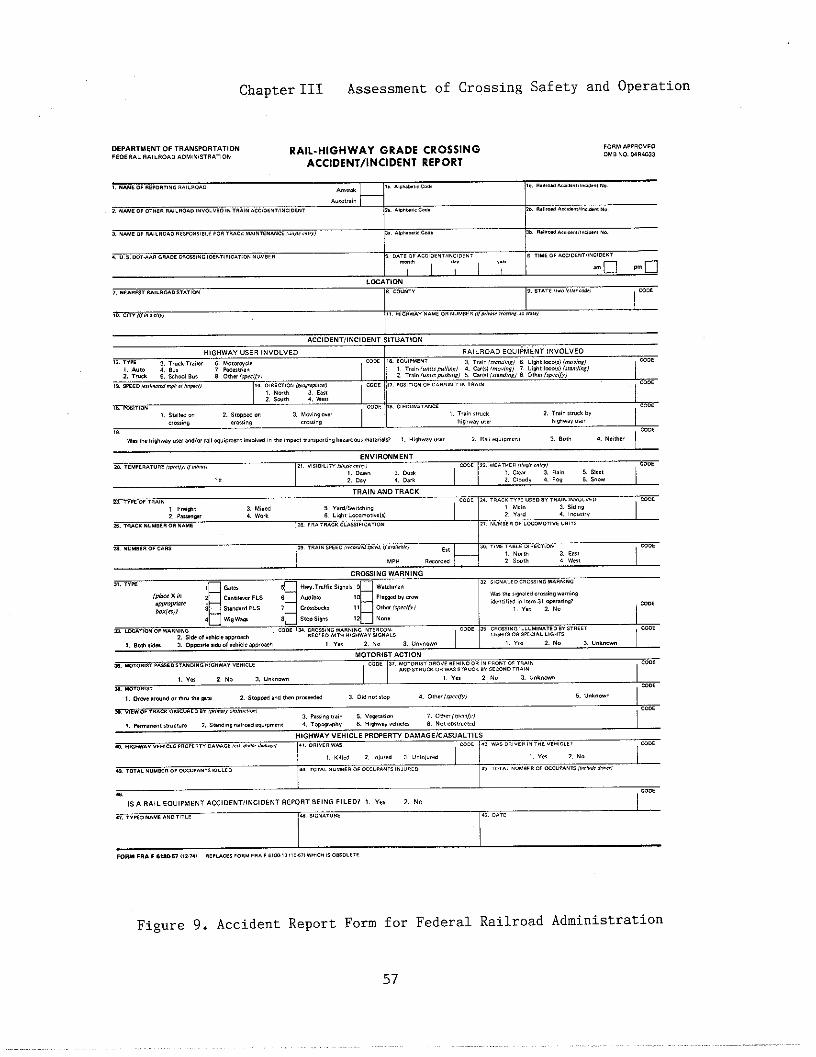
Chapter111 Assessment of Crossing Safety and Operation
Figure 9. Accident Report Form for Federal Railroad
57
Administration
,..
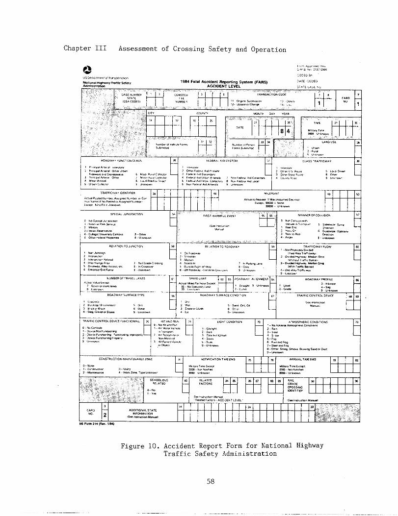
Chapter 111 Assessment of Crossing Safety and Operation
I. . .,,,,.,., 4,
AC,.., ,. .M,., , .,. ,..”- k..,,,C.ce,--,-- “., -.
. ,,,,,“inMF”L, ”EM,
Q
.
5,
d..
Figure 10. Accident Report Form for National HighwayTraffic Safety Administration
58

Chapt2r III Assessment of Crossing Safety and
,..,.,..,,..,,,,,,,?3 (,,4!:!,.,.,,oaf.
,..
Operation
,.

Chapter III Assessment of
?3,,,,,,.:,:,.!,,,,“,,,.,,..,,,,,,,.,,Wi>.ml.4..,,rr.fr.S-,,Mti”,,!m!m
Crossing Safety and Operation
,,,,..,,,,,,,,.,,.,,.“,,,;,,..,,9S4Fa,.1Acclde”tRew”l”gSys,e~(FARS),.,,,,,,,,,”
PERSON LEVEL ,,. :,, ,:,, ”,” ___...
Sir, c..,, .,, .
T~ “:,3,,,,, q:*A~
T*.NSACTION...E ? B : CA.. ~
,,,,,
(.s. . ..ss),, o..,ml sum,=..
m “M,!.., ch.-3
... ,s), ,,.
,,- 2,* ,W, IM,
Figure 10. AccidentTraffic Safety
t
IS5.,I,GPOS!T!O. 1.1
t
0,.,..,,, . 1111 .
-– NO!A,,,=@mm . . . . . . .
. ...” m,, “w.
Report Form for National HighwayAdministration (Continued)
60

ChapterIII Assessment of Crossing Safety and Operation
Ttis::?&”mw“.. .*Am- 0, -Nsmm.rlo.
SWU’O!’”M”OWA: ztk?L:m&’% MOTOR CARRIER ACCIDENT REPORT
Otig~naland two copies of MCS 50-T shall be filed with the &rector, Regional Motor Carrier SafeW Ofice, FHWA, asWunrd by 394.9. Copy shall be retained !“ Carr,er,s file. Grcle or (X) appropriate boxes below.
1. Name Ofcarrier (Co,Do,ate b“si”ess “area) 2. Principal Address (Street and .6, Citi. State, ZIP Code.)
pa) [z-w
w
Figure 11. Accident ReportMotor Carrier
61
Form for Bureau ofSafety
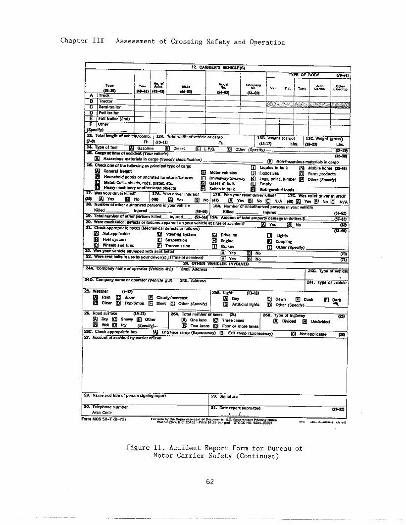
Chapter III Assessment of Crossing Safety and Operation
I A,,.Code I .. . . ..J . . . . . . . .. . . . . .
Fwm M= 5&T (&72) F., ,.!. by,,. ,Uwri”,md.ti d OW”m.”,,. “.s. .Wmmm, ,.”.” O*&,W.,,,”*”, . .. . *MO, %,=. S*., *, M. s,... . . . m
Figure 11. Accident Report Form for BureauMotor Carrier Safety (Continued)
62
of
Chapter III Assessment of Crossing Safety and Operation
tion Bursau (MTB) of the Research andSpecial Programs Administration(RSPA). An immediate telephone no-tice is required under certain condi-tions and a detailed written reportis required whenever there is any un-intentional release of a hazardousmaterial during transportation ortemporary storage related to trans-portation. Accidents are to be re-ported when, as a direct result ofhazardous materials: 1) a person iskilled; 2) a person receives injuriesrequiring hospitalization; 3) esti-mated carrier or other property dam-age exceeds $50,000; or, 4) a situa-tion exists such that a continuingdanger to life exists at the scene ofthe incident. The form used forreporting these accidents to MTB isshown in,Figure 12.
B. Identification of Crossings forFmther Analysis
A systematic method for identi-fying crossings that have the ,mostneed for safety and/or operationalimprovements is essential in order tocomply with requirements of the Fed-eral Highway Program Manual (FHPM),which specifies that each Stateshould maintain a priority scheduleof crossing improvements. The prior-ity schedule is to be based on:
o the potential reduction in thenumber andlor severity of acci-dents;
o the cost of the projects and theresources available;
o the relative hazard of publicrailroad-highway grade crossingsbased on a hazard index formula;
0 onsite inspections of publiccrossings;
o the potential danger to large num-bers of people at public crossingsused on a regular basis by passen-ger trains, school buses, transitbuses, pedestrians, bicyclists, orby trains and/or motor vehiclescarrying hazardous materials; and,
0 other criteria as appropriate ineach State.
Various hazard indices and acci-dent prediction formulae have beendeveloped for ranking railroad-high-,Jay grade crossings. These are com-monly used to identify those cross-ings that are to be investigated inthe field. Procedures for conductingthe onsite inspection are discussedin the next section. Some hazardindices incorporate accident historyas a factor in the ranking formula;if not, this factor should be subjec-tively considered.
There are several advantages ofusing a hazard index to rank cross-ings. A mathematical hazard indexenhances objectivity. It can be cal-culated by computer, thus facilitat-ing the ranking process. As cross-ing conditions change, a computerizeddata base can be updated and thehazard index recalculated.
The hazard indices or accidentprediction formulae commonly used arethe Peabody Dimmick Formula, the NewHampshire Index, the National Cooper-ative Highway Researth Program Report50 Form,,la (NCHRP 50), and the U.S.DOT Accident Prediction Formulae.Several States have developed theirown formulae.
1. Peabody Dimmick Formula
The Peabody Dimmick Formula,published in 1941, was based on fiveyears of accident data from 3,563rural crossings in 29 States. It is
63
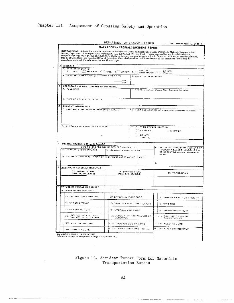
Chapter III Assessment of Crossing Safety and Operation
Department OF TRANSPORTATION ..,. . . . . . . . . 0.s ,., ,,.,, ),
HAZARDOUS MATERIALS INCIDENT REPORT
,NSTR”CT,ONS: S“,,!!’, t,,i, ,,,”,, i“ d.,,,,,,,,, ,. ,,!? ““..,,,,, 0,,,,, “~ “?,,!,,””s ,V.,eti,, 0,,.,,,””,, M.,erfi,, T.J”sP”,,I,;o”““r., u, L),,,l,,,,>, c”! ,,, T,4. SP,,,C4,,. ”, ,,’,,,h,,, g,,>., i~.c. 2“59”, (ATTN: “p. 0,”.). If ,p,,. ,Io”id.d i., ,ny,i, cm ~sinddequa,e,
\cc,,,,,, .,. ,,r~, ,,, ”, ““d., s<,,,”” E,, ,,!/., ”,,,,,,, ,,,,., ,,, ,,>.,.,,, nun!he, bums cam,,,,,.,. CoPie, “f ,,,i, ,“, m, ,“ ,,m,,<d q“znt,,ic,,
m,, ~ ohl,m,d f,”., the D&c,”I, Offic. <,f ~a,d”u, Mote,Id, “P..J,,00,. Addi,iora, COBI,, h ,,i, P,tx,,kd farm., ,.., Mr.,r”d”c.d .,, d “,.,, ,, “n ,h. w,.. s.,. ,“d k,. d ., ..&r.
,. s“,,.,.. ,.,,. ,.,.,,,,..,,0. . . .
j
Y,,s“, ,,,.. ,,,,.s ,,,.,. ,,
::..: CA R.,,. .,, :$.1.,,.., ,0,.,.
!,. s.,,,.,
,,.,. s, (“>u R, Es, ,0s5 AND D+MAGE
. . . ,0 ..,..00 as..,..,,. s ,.”07”,. !,. ,s,,..,,. . . . . . . ., ..,, ,.O .R
,,. .“. s.. ,..s.., ,.,.., O }2. . ...,, ,,. $.., .,.., O . . . . . . . . . . . . . . ,NCL”., NG ..,,
. . 0, CO NT9M, NA, ,0. ,R. ””d o,,,”
..1,.,,,
,4. .s,,.. ,.. ,.,,. .”..,,,, ., ..,,. OO”, .A, CR, AL, .= L,,, EO
$
H. ZARDO” S ..,,,,.,, ,,”0.,,0 —
,,. ... . . . . ..s. 16. ,., ,,, . . ..; ,
1.*. 172,10?, C.I.3, 1.%. 172.$01. Cot., ),,. T. AD&NAM.
..,,,, OF PACK.,,”, ,,,, ”,,
, a. !.. ?,* .!, ,.,.,, ,...,. h,,.,
:%iE-- S=
,!, ) LOOSE FITTINGS, “AL” ESO. ,,2, FAILURE o, ,NN, m
I
!i,,.,c.,........ ,,,,.,.,.co..,,,..,,,.<”,.,,,,,9.SPACEFOR.0,“s,ON.“,rm 00, F ,mo., (,,.,0) ,9,,,76)I,d i,,,,,:,, ,,,l,,,. ,,, i,l.”,,,<,,l(c ,S,c$,gn., i”,, ,., ,,,,., ,2.
Figure 12. Accident ReportTransportation
Form for MaterialsBureau
64
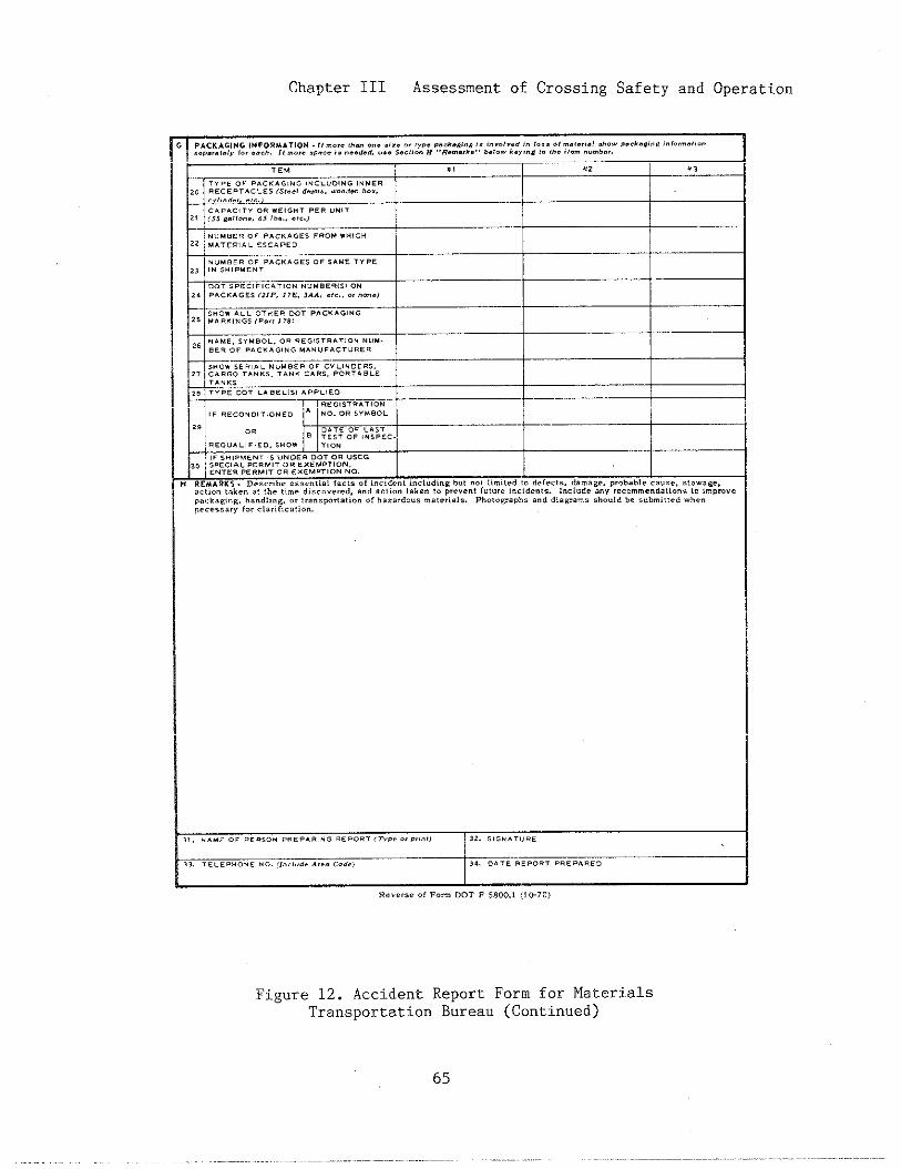
Chapter 111 Assessment of Crossing Safety and Operation
Figure 12. Accident Report Form for MaterialsTransportation Bureau (Continued)
65
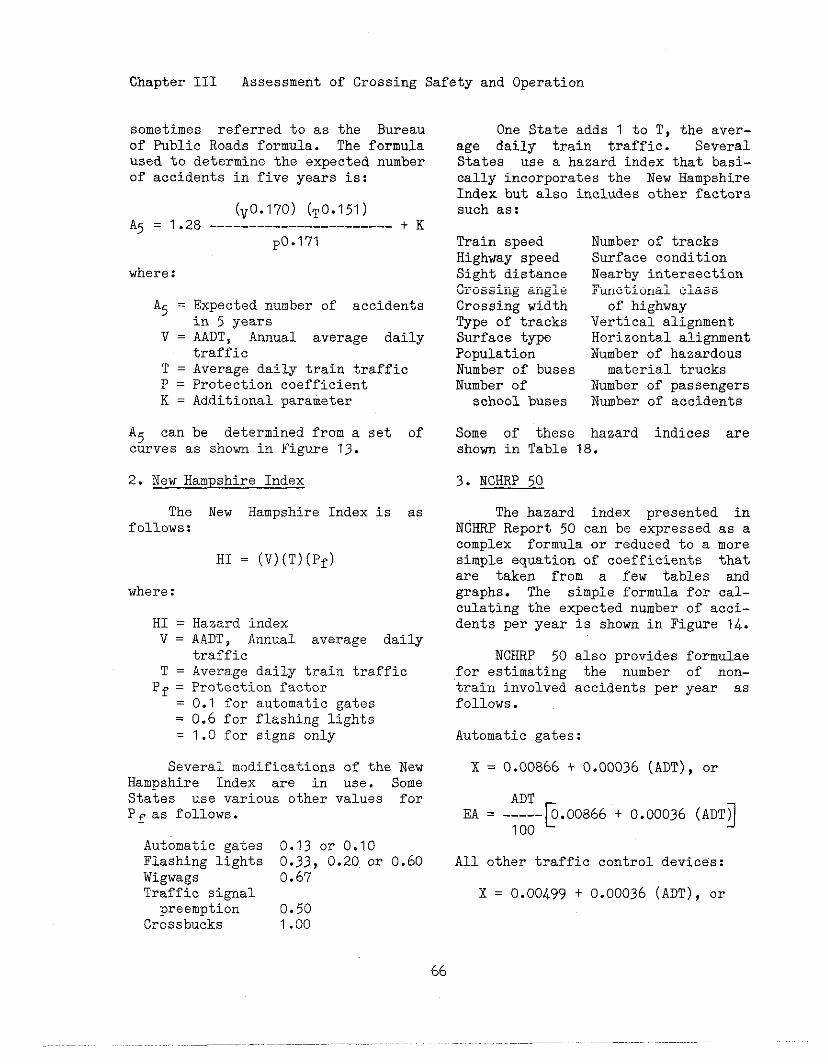
Chapter 111 Assessment of Crossing Safety and Operation
sometimes referred to as the Bureauof Public Roads formula. The formulaused to determine the expected numberof accidents in five years is:
(V0.170) (~o.151)A5 = 1.28 -----------------------+ K
po.171
where:
A5 = Expected number of accidentsin 5 years
V = AADT, Annual average dailytraffic
T = Average daily train trafficP = Protection coefficientK = Additional parameter
A5 can be determined from a set ofcurves as shorn in Figure 13.
2. New Hampshire Index
The New Hampshire Index is asfollows:
HI = (V)(T)(Pf)
where:
HI =v=
T=Pf =
——
Hazard indexAADT, Amual avsrage dailytrafficAverage daily train trafficProtection factor0.1 for automatic gates0.6 for flashing lights1.0 for signs only
Several modifications of the NewHampshire Index are in use. SomeStates use various other values forPf as follows.
Automatic gates 0.13 or 0.10Flashing lights 0.33, 0.20.or 0.60Wigwags 0.67Traffic signalpreemption 0.50
Crossbucks 1.00
66
One State adds 1 to T, the aver-age daily train traffic. SeveralStates use a hazard index that basi-cally incorporates the New HampshireIndex but also includes other factorssuch as:
Train speed Number of tracksHighway speed Surface conditionSight distance Nearby intersectionCrossing angle Fuctional classCrossing width of highwayType of tracks Vertical alignmentSurface type Horizontal alignmentPopulation Number of hazardousNumber of buses material trucksNumber of Number of passengers
school buses Number of accidents
Some of these hazard indices areshorn in Table 18.
3. NCHRP 50
The hazard index presented inNCHRP Report 50 can be expressed as acomplex formula or reduced to a moresimple equation of coefficients thatare taken from a few tables adgraphs. The simple formula for cal-culating the expected number of acci-dents per year is show in Figure 14.
NCHRP 50 also providesfor estimating the numbertrain involved accidents perfollows.
Automatic gates:
formulaeof nOn-year as
X = 0.00866 t 0.00036 (ADT), or
EA = -~-~. 00866 t 0.00036 (ADTj
All other traffic control devices:
x = 0.00499 t 0.00036 (ADT), or
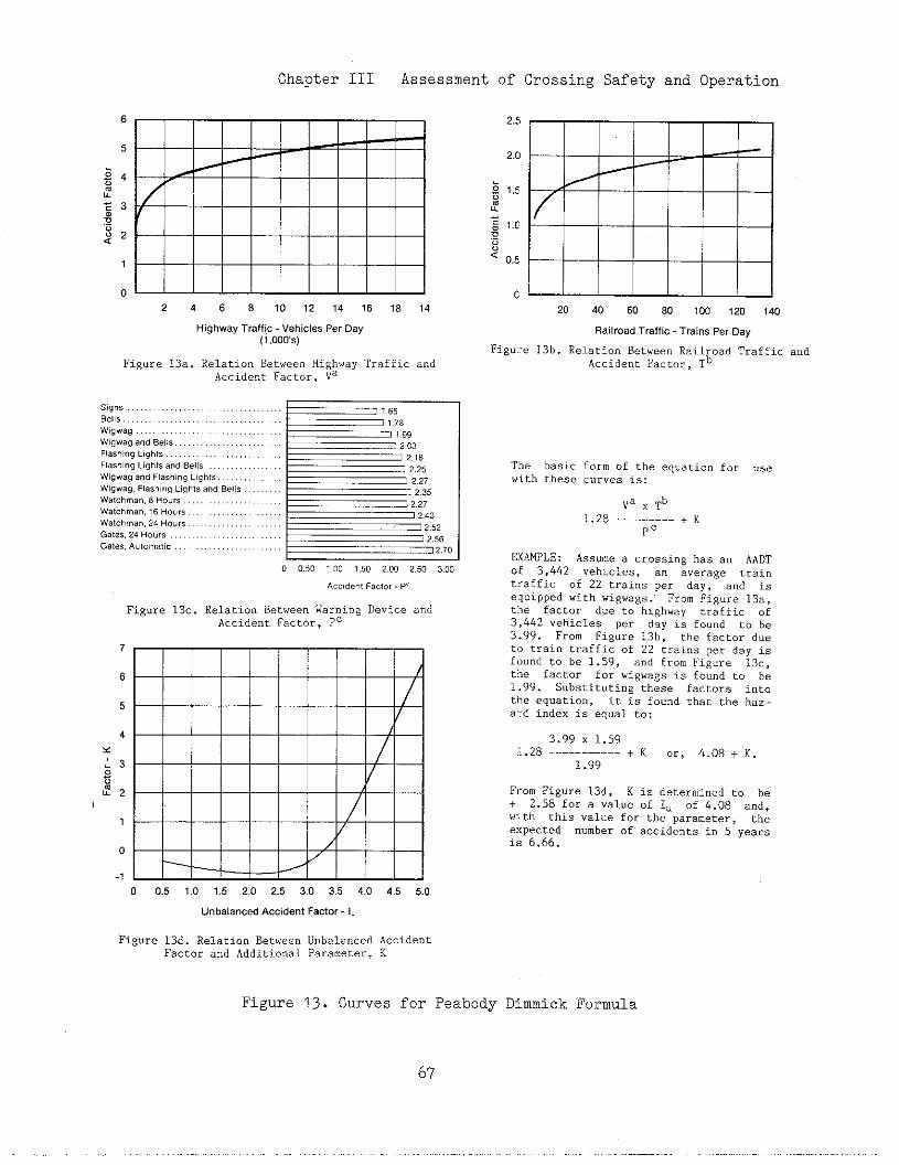
Chapter III Assessment of Crossing Safety and Operation
2468101214 161814
Highway Traffic Vehicles Per Oay
(1,000$)
Figure13.. RelationBetweenHighwayTraffica“dAccidentFactor,Va
sag”, . . . . . . . . . . . . . . . . . . . . . . . . . . ,,65Bells, . . . . . . . . . . . . . . . . . . . . . . . . 1.78wQw,g . . . . . . . . . . . . . . . . . . . . . . . . . . 1,99wgwaga”d Bells . . . . . . . . . . . . . L 2,03F!ashi”Q Lights . . . . . . . . . . 2.18F1a.hi”n tiahtsa”d Bells,...,,...,,. — 2.25
= 2,27
T 2,3522,27
WgWaQ-an; flashing Lights..
Wgwag, Flashing Llghlsa”dBells .,
Watch m,n,8Ho”rs, . . . . . . . ,,
watchma”,,6 Hoers,... . . . . . . . .
W,tchma”,24 Ho”rs ,...
G8t,,,24HO”,,.............,..
Gat,*, A.t0.8,1 C.........,,..::::::s6
5
4
0
-1
12.43
= 2.52
- 2.56
-2.701 1
0 0,50 1,00 ,,50 2.00 2.50 3.00
Acc’dent F,’,., Fe
Figure 13..RelationBetweenWar”i”gDeviceandAccidentFactor,Pc
0 0.5 1,0 1.5 2,0 2.5 3.0 3.5 4.,0 4.5 5.0
E20 40 60 80 100 120 140
Railroad Traffic Trains Per Day
Fig”]:. 13b. Re].ation Between Railroad Trafficar,dAccident~acror,~b
The basicf“rmof the eq”atio,,for usewith these curves is:
Va x cb
1.28 --------- + K
P’
EXAMPLE: Ass”.. a crossing has a“ AADT
.f 3,442 vehicles, a“ average train
traffic of 22 trains per day, a“d is
equipped with .igwa~s. Fro. Figure 13.,
tlbe factor d“e to highway traffic of3,442vehicles per day is fo””d to be3.99. From Fig”r.13b, thefactordueto cr.<”trafficof 22 trainsper day isf“undto be 1.59, a“d fromFiRure 13.,the factor for wigwaRsis foundto be1.99. Substitutingthese factors inc.theequati.”, it is fo””dthattbe haz-a]:dindexis equalto:
3.99x 1.591.28-----------+ K .,, &.08+ X,
1.99
FromFig”..13d, K i. determinedto be+ 2.58for a ..1”,of 1“ of 4.08 and,with thisvaluefor the parameter,theexpected numberof accidentsin 5 yearsis 6.66.
Unbalanced Accident Factor -1,
Fig”.e13d.RelationBetweenDnbalanced Accident
Factor a“d Additional Parameter, K
Figure 13. Curves for Peabody Dimmick Formula

Chapter III Assessment of Crossing Safety and Operation
Table 18. Variations of New Hampshire Index
(SD + AX + NTR). . - —---- . . . . . . . . .
4
3:(TT+TTR +SD+AN+AL+L+C+ vsu+w+L1)
HI = (V) (T) ------------------------i~;-----------------------
4:(Pf)(Vf)(T) (TS) (NTR)
HI = -----------igr----------+ (70Aa)2+ 1,2(SD);Aa = (V+ -f;-)(~)
5: HI = .l(Pf)(Af)(rl)+ (AN)(NTR)(s) (.5L)+ T5((Fcx p) + (i~-~6~-)+ SB)
(Vf) (Pf) (T)6: HI = ---------------------------------
VR + ~N + r ~+ Hs+G+SD+AN
7: HI = (.01)(v) (T)+ (.1)(HS)(TS)+ (SD) (m) (TR)(NTR)(AL)+
(A%+ I) (RF)(LF)(Pf)+ (SB)(SBP)+ (10)(m)
where :
A5 = Numberof accidentsi“ fiv,eyearsAa = Numberof a.cide”tsper yearA = AccidentfsctorAl = Factorfor highway alignment
AN = Factor foraPProacba“~leFC = Factorfor f“”cti””.1classG = Fact”rforapproachgrades
HI = Hazard T“dex
IN = Pa<:t”r f“r hazard.”.,“aterialsvehicles
HS = Factor for hishway speed
L = Factorfor““”!berof 1s..s1,1= Factorfor 10..1interferenceLP = Factorfor localpriorityNTR = Factorfor““mberof tracks1>= F,,,”,for PoPLll.tiO”P = Pr<,tecti””factorRF = Factorfor rid-ability
Source: Ref. 5
EA = -~D-~.00499 + 0.0036 (ADT~
where:
X = Probability of coincidental
vehicle and train arrivalscaled by 10-3
S = Factorfor surfacetypeSB = Numberof schoolbusesSBP = Numberof schoolb“. passenger.SD = Factorfor sightdistanceT = Average“umber“f Crai”sper day
Tf = Numberof fasttrainsT, = Number“f slow trains,~ = Trainfactor,r~= Factorfornumberof nightt..i.sTR = Factorfornumbera“d type of tracksTS ,=Factorfor trainspeedsTT = Faccorfor typeof trainmovementsTTR = Factor for tyPe of tracks
V = A“T)u*ll average dailytrafficVf = Factorforan”.alaverage daily
tr.fficVSD = Factorforverticalsightdistancew = Factorfor crossingwidth
ADT = Average daily trafficEA = Expected number of accidents
per year
Modifications of the NCHW 50hazard index exist. For example, oneStatefs formula is:
68
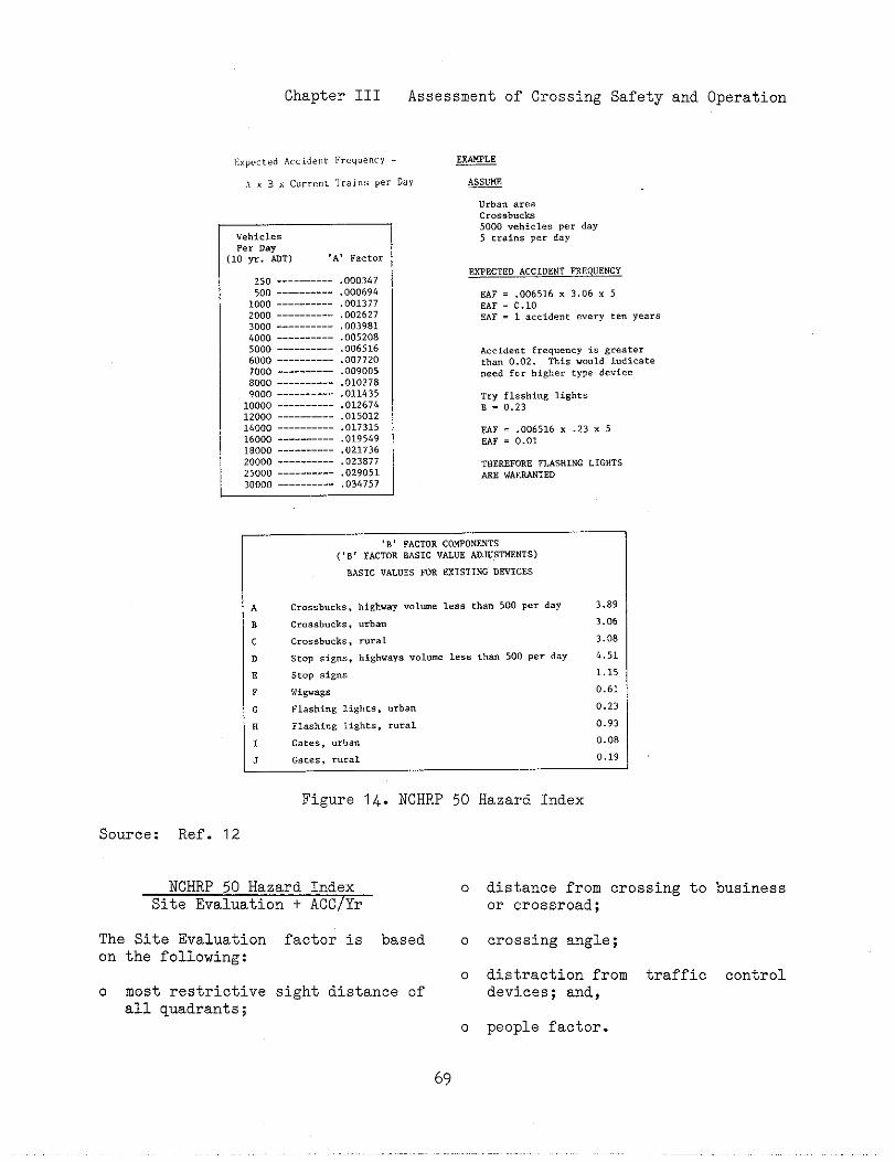
Chapter III Assessment of Crossing Safety and Operation
1:.Pt,c,,~Accidek>c Fr. Q.~.. Y = ~
A x “ x current ~r.i”s per D.Y m
“ehicles
P,, Day10 yr. ~T) ‘A, Fact..
250 ---------- .0003h7
500 ---------- .0006941000 ---------- .001377
2000 ---------- ,0026273000 ---------- ,003981
4000 ---------- .005208
5000 ---------- .006516
6000 ---------- .0077207000 ---------- .009005
8000 ---------- .0102789000 ---------- .011435
10000 ---------- .01267&
12000 ---------- .01501214000 ---------- .017315
16000 ----—---- .019549
10000 ---------- .02173620000 ---------- .023877
25000 ---------- .029051
30000 ---------- .034757
Urban areaCc.ssb.ck
5000 vehicles Per day
5 train. Per day
EXPECTED ACC lDENT ~EQUENCY
EAF = .006516 x 3.06 x 5EAF = 0.10
EAF = 1 accident e“ery ten yeers
Accident frequency is ~reater,ha” 0.02. This vo”ld indicate
need for hi~her type device
Try flashing lights
B = 0.23
~F = .006516 x .23 x 5
mF = 0.01
THEREFORE =ASHING L lGHTS
ME WARMED
vB, FACTOR COWON~TS
(, B S FACTOR BASIC VALUE ADJUS~NTS)
BAS 1 C VALUES FOR EXIST lNG DEVICES
A
B
c
D
E
F
G
N
1
Crossb”cks, highway volume 1.s, than 500 P.= day
Cr.ssb”ck, , urban
Cro,ab”cks . r“ra L
SCOP si~ns, highways “olme 1.,s than 500 Per day
stop .ig”s
Wig..g.
F1ashi”& lights, “rba”
Flashing li8ht,, r“Tal
Gate, , “rb,”
3.89
3.06
3.08
4.51
1.15
0.61
0.23
0,9?
0.08
J Gate, , rural 0,1:
Figure 14. NCHRP 50 Hazard Index
Source: Ref. 12
NCHRP 50 Hazard Index 0Site Evaluation t ACC/Yr
The Site Evaluationon the following:
0 most restrictiveall quadrants;
factor is based o
0sight distance of
0
distance from crossing to businessor crossroad;
crossing angls;
distraction from traffic controldevices; and,
people factor.
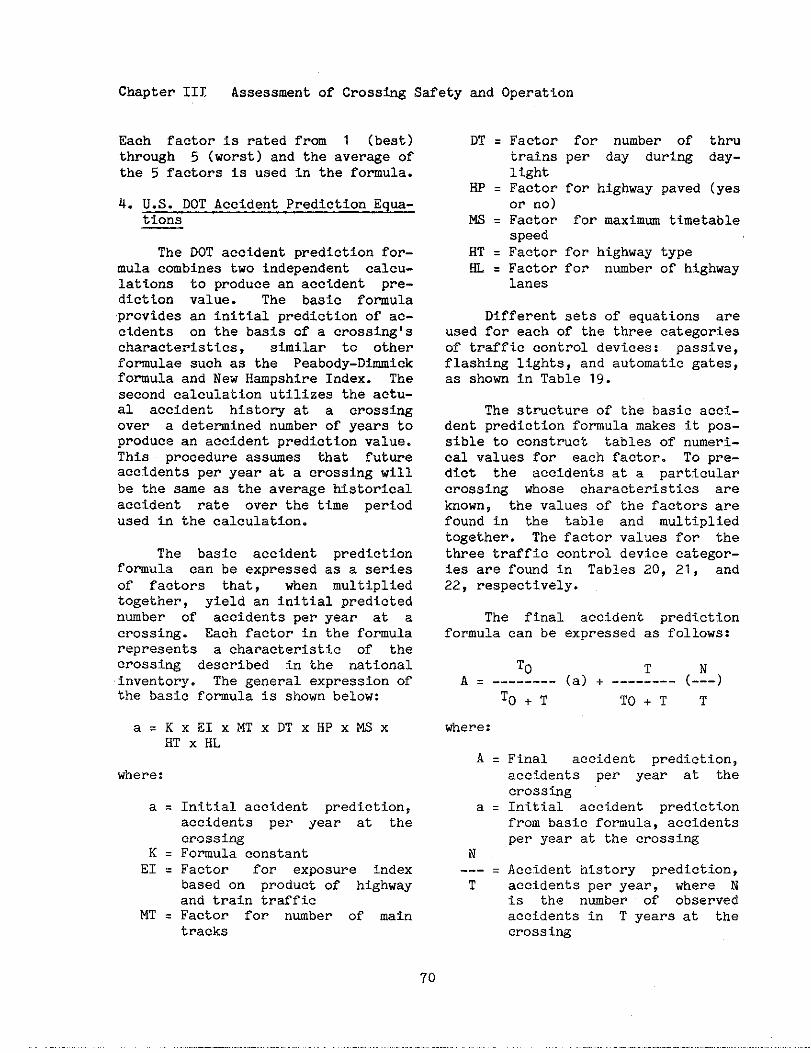
Chapter 111 Assessment of Crosstig Safety and Operation
Each factor is rated from 1 (best)through 5 (worst) and the average ofthe 5 factors is used in the formula.
4. U.S. DOT Accident Prediction Equa-tions
The DOT accident prediction for-mula combines two independent calcu-lations to produce an accident pre-diction value. The basic formulaprovides an initial prediction of ac-cidents on the basis of a crossing!scharacteristics, similar to otherformulae such as the Peabody-Dimmickformula and New Hampshire Index. Thesecond calculation utilizes the actu-al accident history at a crossingover a determined number of years toproduce an accident prediction value.This procedure assumes that futureaccidents per year at a crossing willbe the same as the average historicalaccident rate over the time periodused in the calculation.
The basic accident predictionformula can be expressed as a seriesof factors that, when multipliedtogether, yield an initial predictednumber of accidents per year at acrossing. Each factor in the formularepresents a characterist~.c of thecrossing described In the nationalinventory. The general expression ofthe basic formula is shown below:
a= KxEIx MTx DTx HP XMSXHT X HL
where:
a=
K=EI ❑
MT ❑
Initial accident prediction,accidents per year at thecrossingFomula constantFactor for exposure indexbased on product of highwayand train trafficFactor for number of maintracks
DT = Factor for number of thrutrains per day during day-1ight
HP = Factor for highway paved (yesor no)
W = Factor for maximum timetablespeed
HT = Factor for highway type~ = Factor for nwber of highway
lanes
Different sets of equations areused for each of the three categoriesof traffic control devices: passive,flashi~ lights, and automatic gates,as shorn in Table 19.
The structure of the basic acci-dent prediction formula makes it pos-sible to construct tables of numeri-cal values for each factor. To pre-dict the accidents at a particularcrossing whose characteristics areknown, the values of the factors arefound in the table and multipliedtogether. The factor values for thethree traffic control device categor-ies are found in Tables 20, 21, and22, respectively.
The final accident predictionformula can be expressed as follows:
ToA= -------- (a) + -------- (-1-)
To+T TO+T T
where:
A = Final accident prediction,accidents per year at thecrossing
a = Initial accident predictionfrom basic formula, accidentsper year at the crossing
N--- = Accident history prediction,T accidents per year, where N
is the nmber of observedaccidents in T years at thecrossi~
70

ChapterIII Assessment of Crossing Safety and Operation
Table 19. U.S. DOT Accident Prediction Equations forCrossing Characteristic Factors
Table 20. U.S. DOT Accident Prediction Factor Values forCrossings with Passive Warning Devices
Source:
miim”m-
48$*,<;,‘-
him m, ,,=. “’,,.., ,,m,.b,a
K !!=,, , ,.t,, ,, T,*. “=Tr.ck. ~ ,,.,.s m ,.,,, “, SAd ,, ,.,. m .
0’ ,.m o ,.m o ,.W ,C,=,],.m o ,,m
.—.. -—
.m,,a, ,.2, ,,23 , ,.,7 * (..) ,.5’ 5 ,.,’
01811I.m , ,.W
:: 3,30 : ,,,2 ,.%~: ~g 2 ,.m
,, : ,.,, , ,.,,,,W
: ,.6, : ,.12[:: ;
,, w ,.0, , ,.,, & ,.m07816 0,74 :,
3, 5.86 , ,.8, 5 ,.>520 ,.,7 0%,7 0.6, ;::/
51 2 6.,, 6 3,,, 6 ,.,,25 ,.,1 m,, 0.6, :m 1.26
8, - ,20 ,.,, ,.6,l.m
,,, ,m 9.*935 1.,,
: ,,6,: ,,m,
1.X,0, ,m ,,.78 9 ~;g
, ,,m2 ,.,,
m, 4W ‘*.M . ,.4740, 5W ,,.,,xl ‘w ,,.0,
11!;0 ,.7, ,5 ,,,,21-% ,.9, ,.,9
a, ,m ,4.8, 3140 ,.m70, - lm ,6,2,
2 ,,6,614 2.B
,m, - ,,m ,7.9,70 ,.7,
,.7s130, - ,6w ,9.37 : ,.85la, ,m 20.s,,m* ,,m ,,.42
8, ,.92. 2.W
25,, ,W ,,.9,m, ,W 25.%‘m, ,m *g. *6,Wl *W ,2.7,ml ,Wm ,,.,,
Iml - ,5M 3,,7,15W1 - ,- 44.4,2W1 2- 4,,,,,m, m 5,,653m1 4m ,,.,84~1 m 60.875m1 m 6S, M6~, 7- 68.8,7ml m 7,,7,-, ,1- 7,,’4
llml Im a’,’,13W, ,,m ,,.,,lam, 23m ,m.,,,-, m ,W.,’3-, 37- ~,,
Ref. 7 ----~
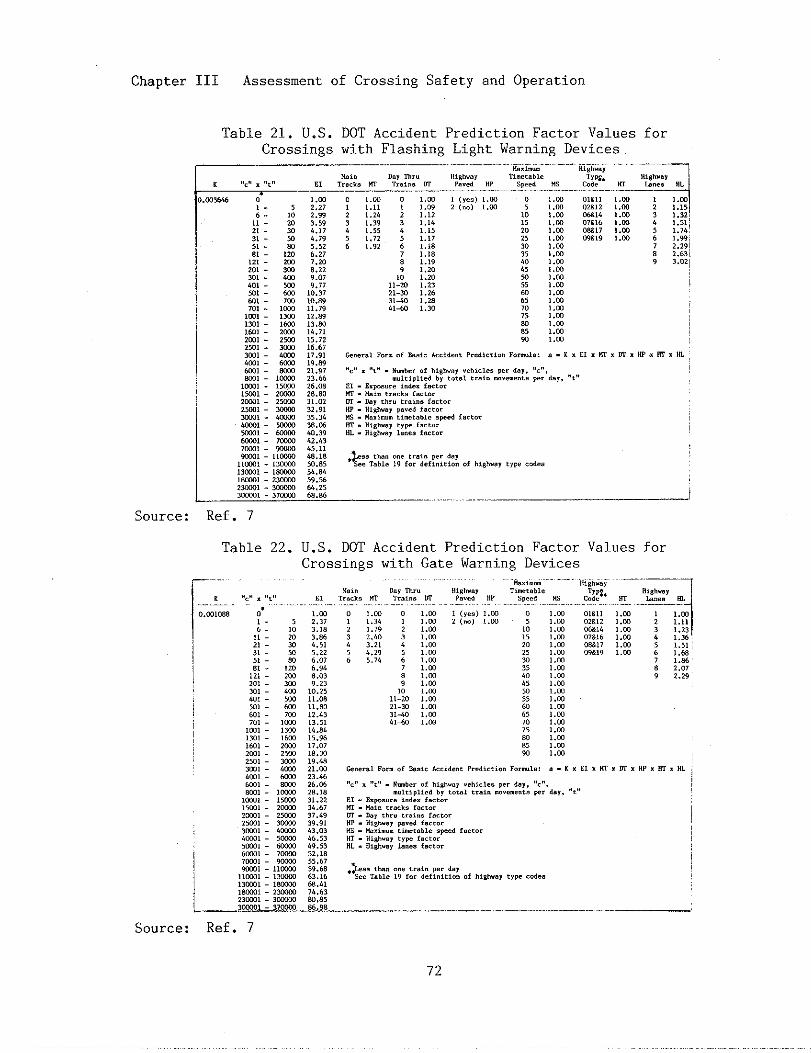
Chapter III Assessment of Crossing Safety and Operation
Source:
Table 21. U.S. DOT Accident Prediction Factor Values forCrossings with Flashing Light Warning Devices
..“,,,..,,.”.,“,;[~1::: ,,W
1,W, .m, .m, .m, .W
Ref. 7
Table 22. U.S. DOT Accident Prediction Factor Values forCrossings with Gate Warning Devices
Source: Ref. 7
am
, .m,.,,,.,9,,,0,.2,::;:
, .m, .m
, .m, .W1.m,.m,.m, .m
8.
,.m,.,,,.*31,36,,.,,,,68I.M’2.072.2,
.———--..,——...—.—— ------ .—-..,. ..-..-. -... ..
72
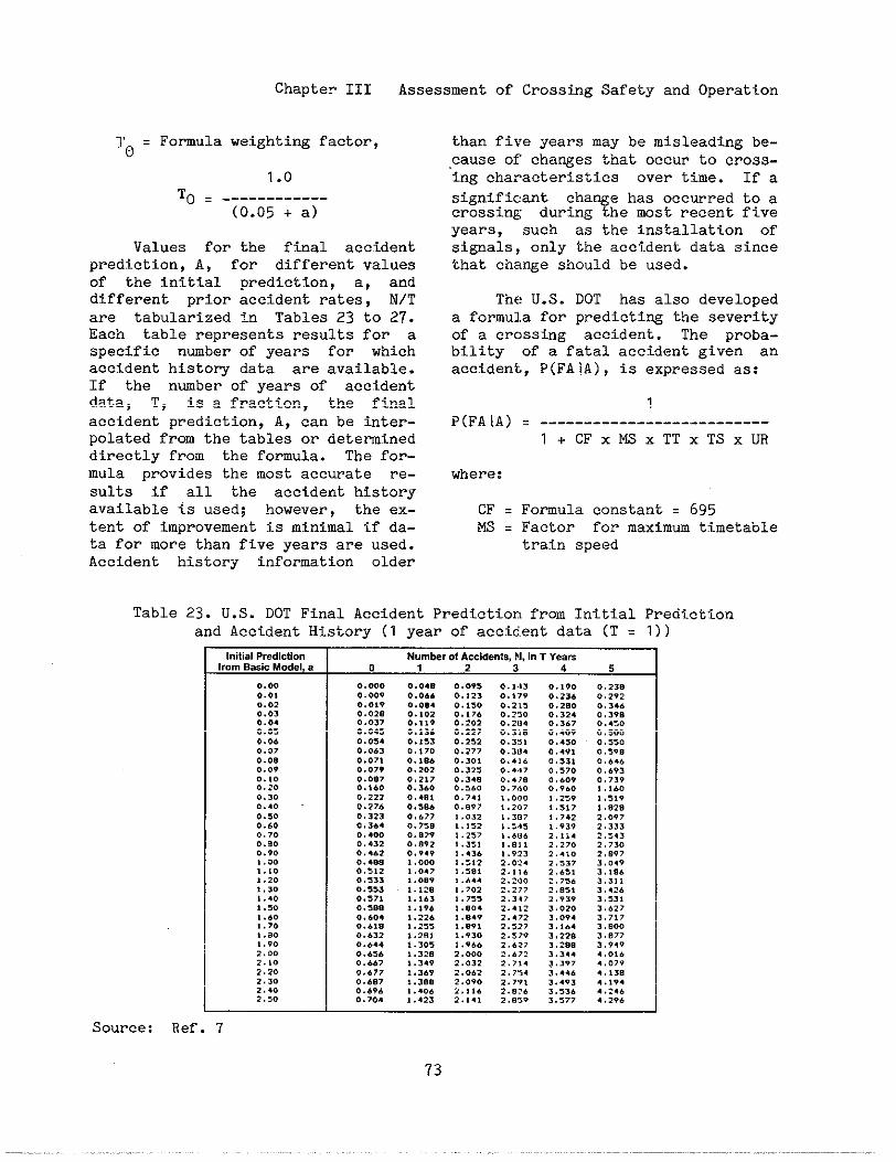
Chapter III Assessment of Crossing Safety and Operation
TO = Fomula weighting factor,
1.0To = ------------
(0.05 + a)
Values for the final accidentprediction, A, for different valuesof the initial prediction, a, anddifferent prior accident rates, N/Tare tabularized in Tables 23 to 27.Each table represents results for aspecific number of years for whichaccident histo~ data are available.If the number of years of accidentdata, T, is a fraction, the finalaccident prediction, A, can be fiter-polated from the tables or detemlneddirectly from the formula. The for-mula provides the most accurate re-sults if all the accident historyavailable is used; however, the ex-tent of improvement is minimal if da-ta for more than five years are used.Accident history information older
than five years may be misleading be-cause of cha~es that occur to cross-
‘ing characteristics over time. If a
significant change has occurred to acrossing during the mst recent fiveyears, such as the installation ofsignals, only the accident data sincethat change should be used.
The U.S. DOT has also developeda formula for predicting the severityof a crossing accident. The proba-bility of a fatal accident given anaccident, P(FA!A), is expressed as:
P(FA1A)
where:
CF =MS =
1= --------------------------
l+ CFXMSXTTXTSXUR
Formula constant ❑ 695Factor for maximm timetabletrain speed
Table 23. U.S. DOT Final Accident Prediction from Initial Predictionand Accident History (1 year of accident data (T = 1))
Initial Pretictio. Number.1 Accidents, N, i. T Yeavsfrom Basic Model, a 01234 5
0.00 0.000 0.04. 0..,, O,,*, 0.,,0 0.,3.
0.., 0.00, 0.0.6 0.,23 .,,,, 0.,3. .,,,,0.02 ..0,, 0...4 .,,,0 ..,,, 0.2s. 0,34.,.03 0,02. 0,,,, 0.,76 .,250 0.3,, 0,,,,.,.4 ,,0,7 0.,,9 .,,02 .,,”4 0.,., ..4:00.0, 0.04, 0.,,. 0.,2, 0,,,, .,4., .,s00
0,06 0.0s4 ..:53 0.2s2 0.351 ..450 ~,5500.07 0.063 0.,70 0.2,, 0.,04 0.4,, 0,5,8
0.0, 0..7, Q., e. 0,3., 0,,,. 0,,3, 0,,4,0.0, 0.07? 0.>0> 0.325 0.447 ,.,,0 0,6,,..,0 0.08, .,,,, 0.,.. 0,.,, ,,6., .,,,,0.,0 0.%60 0.160 0.,.. ,,7,0 0,,6. ,,,..0.30 0.22, O,*8, 0.74, ,,0., ,.,,, ,.5,,0.4, ..27. 0.3.6 0.897 ,,2., ,,3,7 ,,.,s0.,. 0.323 ..677 x,.32 ,.3., ,,,.2 ~,o,,O.*, .,3.4 0.,,, ,,,,2 ,.,4, ,.,3, ,,,33..70 0..00 0.,,, ,,,,7 ,..., ,,,,4 2,:430.9, 0,43, 0,8,2 ,,3,, ,.*, , ,. ,7. 2,7300.,, 0,..2 0.9,, ,,43. ,.,,, ,..,0 2,,,7,.00 0 . . . . 1 .0.0 x,:,, ,.02. ,,,,, ,,0,,,.,. 0,5,2 ,,0,, ,,,8, ,., ,. ,,.,, ,,, s.
,.,, 0.,33 ,.0,, ,,,44 ,.,.. 2,7,. 3,3,,
i,,. 0.553 ,, ,2, ,,,., 2.,,, 2,,,, 3,42.,.40 ..,7, ,.,,3 ,,,,, ,,,4, ,,,,, ,,,,,
,.,0 0.,.s ,. ,9. ,,,0. ,.4,, 3,0,. 3,,,,,... 0.60, ,.22. ,,.4, 2.,72 3,0,4 3,7,7,.70 O.bla 1.255 1..9, 2.3,, ,,,., ,,,.0,.,0 0.632 ,,2., 1,,,0 ,.,7, 3,,,, ,,,77,.,. 0.644 i.xos 1.966 2,627 ,,2s, ,,9,9,,00 0..,. ,,3,s ,,00. ,..,, 3.,,, 4,.,.,.,0 0,.67 i.,,, ,, ,32 2,,,4 3,,,7 4 ,0,,2,2. .,6,, ,, ,6, 2, ... ,,,,4 3. 4,. ,,,,,2.30 0.6.7 1.300 2.090 ,.,,, ,..,, ,.,,,2,40 0.6,4 1..0. 2., ,. 2.8,, 3.,,, ..2.,2.,0 0.7.. ,.423 ,,,,, ,..,, 3.,7, 4.,,,
Source: Ref. 7
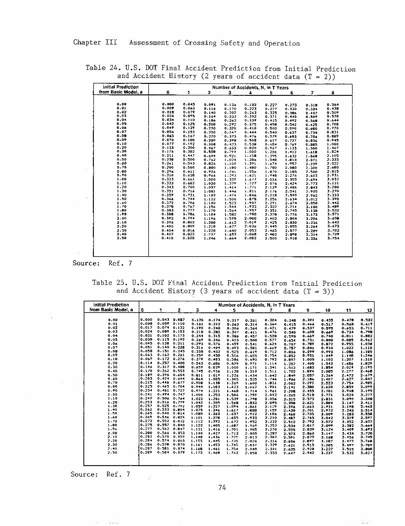
Chapter III Assessment of Crossing Safety and Operation
Table 24. U.S. DOT Final Accident Prediction from Initial Predictionand Accident History (2 years of accident data (T = 2))
Initial Prediction Number of Accidents, N, I“ T Yearsfrom BasIc Model, a 0 <234 5678
r
Source: Kel. I
0.000.0,0,0,0,03,,040.0s0.06..07..0.0,090.,00.20..,..,400,,00.600.7,
0.,0.,,0
,.00,,,0,.20,,30,,..,,,0,..0,,70,,80,.,0
,.002.,02,20,,3,2,.0,,,0
O.W0.00,.,0,.0, .,.0.0340.042,.,.,0.0,...0.,0.,70..077,. ,330.,760,2,,0,,,.0.,,,
0.2,00.,,.0,3,.0.32,.,33,0,,.30 ,3,,0.35,0. 3..,.37,0.37,,,3s30.3.s0,39,0,3,.,,400
0.4..0,..70,,,0
,,04,.,..30,0,,0,,9,... ,00.,,s0.,,,0.,,3
,.,.70,,..0, ,,,.. ,00.,3,20,4470.,0.0.,.30,,s00,.,,,..,,0, ...0,..,0, 700,.,,.., ,3,..,4..,,,.0,7.7.,7770,7860,7,..,,.20,,0,
0,,,.0,,2,0,.2s
0.0,,0,, ,60,,,00.,,40, ,8.0.,0s0,,3..,,,.,,2,.0.209.,30.0.4.>0.,,8. . . . ..,76,.,,,.0.88..,,2.0.,..,.00.1 ..,., ,0,7,..8,,,,.,,.,22,. 140,.,3.,. ,7.,.,,4
,.,9,,.2..,.2,,,.,2s, .2,,,.24.
0,,3.0.,700.2020.2330.2630.2.20,,200,,.70.,730.,9,..,,30..33..,,,0.,, !! .02.1.10,,,1.0,,241,.293,.,39, ,3,.,,4,.,..44,,47., .,..*.,2,*,544* ,,.4, ,5.2, ,,,,,,.,3* ,.27
* ,.40, .6,3*...,
.,,,,
., ,2,0,2430,3.,0,,,,0.37,0.,,0. . . . .,..,60.50,..,3,0, ,,., .000,, !,., .,,.!.,?,1 ,..0, .5,.,, .,,i ..7,1 .,,7,., >,,.,, ,! .,.., .s78, .,0,, ,,,3! ,,,7, ,,,.
2.0.02.0,,2..,62,.,,2.0.,,.0.,
0.22,..,7,0.3,,0,37,,,.,,0.45.0.,.,0.,.0,,,7,0. .,70,.340,,.7, .20,,, ,7,, . . . ., ..74, .7..
, ..70, ,9.,2,0,... 07.2.,,9,.!?6,.2,.2,2,,2,,,,2, 3222.3,,,. ,78,,.02,, .2,2,.4,,,4.,,,.,,2.,0.
0,,730,,,00,3..0,..,.,4920.,,,,.,9...6,70,.,3.. 727..,6,,, !,,,.4,2,..3,,,8,0, ,,,7,,.,02, ,8,,,,7.,,,,,2.42.,..a.
,.,.,2.59.2..342..,.2,7,,2.74,2.7,,
2.,042.,30,.8,,2.,772.,9.,.,, s
0,,,.., 384. ...,.,,.,0.,.,0.62,0..,00. 7,4a .7.60.83.O.,=i .300,..,0, .,.,,.,7,2,23,2. 3s02,,.0,,.03,,.942,,,,2.8432,,,,,,,.,3..,,3..50,., W,.,3,,.,733.,063.,363.2.4
,.2.,3.3,.3.3,6
0.3640,+3,0,,090,,7.0,..4.,70,.,77,
0.83,,..890,,4,, .000,,4.7,, ,2.>.,0,2,333,.,,,2..,0,.,,,2,,3,,,0323,,2,3. 2..,.270,.33,3.390,,..,,,4,,,,,,2,.,7,
3.60.3..4,3.67,
,.7.23.72,,.,,4
-.-
Table 25. U.S. DOT Final Accident Prediction from Initial Predictionand Accident History (3 years of accident data (T = 3))
Initial Prediction Number of Accidents, N, f. T Yearsfrom Basic Model, e 01234 56789 10, jj2
.,000..,0,02.,.,0,040.0,0,060.07,.0,0.0,0.,00.200.30,..,0.,00,.00.,00...0.,0,.00!.,,,,2.,,,.,...,.,.,..0,.,.,.,0,.9,,.0,2 .,02.20,.302,402 .,,
0.,000.0.,0,.,70.,240,.3,. ..3..,0.s0.0,,0.,,80, ..30.0690., ,40.,.6..,700,,.,..,.30,,,,.,22,0,,34.,24,0.,.70,,,30 .2,70.2.20.2.50 .2.,..,720,,7,0,,77
0. 2s..,2.2.,28...,,.0 .2,70,>s?
..,4,0.0,,.,07,0.,89.. ,0,0,, ,,0,,,s0.,400.,,,0.,.20.,?,.,2,7,.3,70.3.,..39.0,42,,,4.6., +.,0..s,0.4,... ,0..,,,.0.3,,0,,3,0,,.0.,,...,,,20,,,7.,,.2
0.,.,0,,7.0,,7,.,,,00,,.,0,,s4
0,,,70,, ,.0.,,,..,,3,., ?,..,,2,.,,,0.,,,.,2,,.,2.,..276
0. +000,.8,0.,,30,6040,..,.,.77,.7,.0,7,,.,7.70,,.40.7790.,,,. ...4. ...4.,*2...83,.,,.0.,..70.,,3,..,,0,.6,0,8700,,7.0, .,,
0,,,,., ,.,0.,900.2!,,,244..,.,.,2930,,,..,3,,0.3,,,.37,0,,.,0,6,,,,,.,0,,, ,0,8.4.,,.,..9.,0.,7.,.00.,..,,,..42, ,.,9, ,.,,,.0,,,.,0,,., ,2,, ,221 .,,,,. ,4.1.,.s,,,,,,, ,6,,,,.0,,, ,,
0.,740,2,,0 .2.,0.2,20.3, s0,34.0.3,6.,.0,..4320 ..,,0, .,30.,.,0.s,,0,,34
,,.,9,. 0s,,, ,3.,.,,3,.,2,t .?.31 .2,,* .3.,,,327t .3.6,.36,, ,37,, .3,2, ...,,.,6,,4,7, ,4,., ,..,,.,,3,,4.,, ..6,
0.,,70.2.30,3060,3+7. . . . .., .,3.,4,,.,.,,0,,,,0.,,60.,0.., .29, .000,. ,2,, .226, .30,,.36?,..,,, ..*, . . . .,.,,?, .,6,,.,,.,..,7,, .,7, .6,,, .6,,, . ..7,,70,,,7,,, .,2,,. 73,1 ,7.,,.,,4, .7.,
0,26,.,3,40.,.4.,4, ,0..,,,,,000.,.10.,s,O..*,0,6,,.,6,0..97,,, ,7,,,3,9,,43., ,,2,* ,...,...2,,7,,, .7,,, .79,, ,s,2, ,s.,, .,8.,.,,,, ,,33* ,,s2,. ,69, .,.,2.0002.0132 ,0, .2..372,.4,,.o, e
.,,.4
. . . . .0..,,..4760.,2,0.,,70.62.0...,.,7,20, 7,.0.,,,
t., ,,$,,,,,.5,,,,..2,,,,.,.,3,,.90,,.,.,,.01.2.0,62. O*,,,,.9,, ,,,,, ,,*2.2,0,.2,,2.,,22.270, .2.,,.3.22 ,3,.2,32,2.34,2, ,,3
0.34s,.4,,0,4,,0.,.0.,,,,0,.s40.707..7,70,,0.0.,,20.s,7, .2,7* .,,2, .70,, ,..,, . . . .,.0,,2.,.,2.,0.,. 2.,2.3,,,.3,.2.,,4,.43.2,46.,,4072,,,22.,,.2.,,,,,,7,,.59,2..0.2..2,2,.3,2.6.,
0.39,0...,0.,370.,.,,,..,0.,3,0,,.,,.8.,0.8,90,,s,, .000, .4.0, ,.,,, ,89.,,0s,,.,,.2.,922. 3*O2,4,,,,,,,2.,?,2..2,,.6.3z.,.,,,73,,,76,,,,,,,,,,72,,3,,. s..2.,,9,,897,,,,,,,,2.2,,42
..4,,0.,,70.,-0..49..740. . . . ...,720.,340.9,3, ,04,,.,0,
, .,43,. *,4,. 0s,,.2.42,4072,,,3,..2.2.70’,.77,
2.*,,2...4,,,,,2.,723,0093,.423,07,,.099,.,2.,.,473.,.8,.,,73.20,3.,,2,.237
,.47. 0.,22,,,., 0..,90..,, ..,,,0.7,4 0.,,.0.s,, ,.*.20,,.,.,9.,::% ,.03,
,,,,,,.0.4 ,.,,,,, ,4, ,.2..,,,.7 ,.,,.
,,.06 ,.,2,,,02. 2.,9,,,277 2...02.472 2,679,,.,7 ,,s47,.7,4 2,,,,,..,, 3..,92.,., ,.,,,3.,2. 3.2773,0,. ,.,4.3.,4, ,..,,,,,,, ,...,3,,49 3.,,4,,2,3 3.,-,.3,, ,.s97,,3,2 ,..3>,.,,, . . . . .3..09 ,.’,3,..,4 3,720,,4,. ,,74,3,,7, ,.,..,.4,7 3,,.9
3.,,, ,.80.3.,32 ,,s27
I
Source: Ref. 7
74
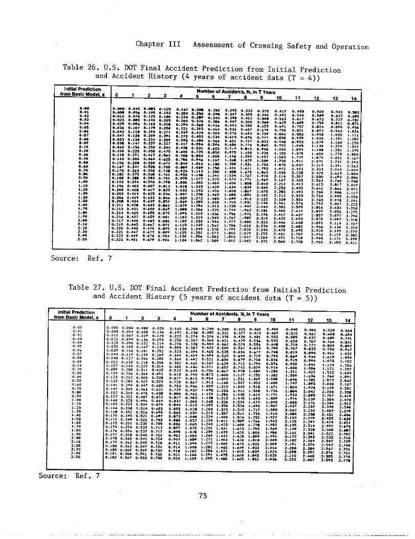
Chapter III Assessment of Crossing Safety and Operation
Table 26. U.S. DOT Final Accident Prediction from Initial Predictionand Accident History (4 years of accident data (T = 4))
I“itlalPrdlctl.n Numbr of Acciti”b, N, 1“ T Yearnfrom Basic Model, . ~,2345 ~789 ,0,, ,2
I13 14
1o.m0..,0..,..0,. ..4. . . .0.0’0.,7O..*0..,..,0,.,00.3.0.4.,.*..’.0.70,.m0.?0,.00,.,.,.m*.,.,...l.-,...,.,0,...,.,0,.W2,1.2.,.2.3.,...2.,0
0.- 0.04,o.m ..m,..0,. 0..,00.02, o.m,0..2, 0...,0.03, 0.,.>..0,2 ..,,,.,,., .,,,,. ..., 0.,3,. ..= 0.,.70...2 ..,,60.,00 ,.,2,..,,, ..2,,., ,43 ..,0...,,, ..,,,0.,,7 0,,+,0.,,, 0.3.3..**2 ..37,... * 0,3,,0.,,, 0.,,,..,,. . ..0.O.NO 0.4....203 ..4,4o.m. 0.,,,0.20, 0..2.,.,,, 0..2.0.,,3 0.4,,0.,,4 . ...,0.,,4 . ...70.,,, ..,.00.2,, 0,4.3..220 0..43..22, . . . . .0,,,, . ...,..22, 0..,,
o.m, ... =0.,., ,,,s,0.,,, ..*W. . . . . . . . . .0.,6, ..,,.0.,,, ..m..,?4 ..,,,O.,W ..*,..22. ..,0,0.,,, 0.,,7o.no.,,..O,,* ..,n. ..., ..,.,0.4.4 . ...,O.* e..,,0.,,. ,.,.,..,M ..,,,. . . . . . . . . .O.,*J ..,,,0.,9. . . . . .0.’., 0.,,,0,.,, e.,m0..,, . ..U..6,2 ..,.’. ..., ..,,4..*., . ..62O..* 0.,.,..6,, 0,,,,0,’,, 0,.,,0,.,, ,,...0.4.7 . . . . .. ...0 ..8,,. ..73 0,,,,,.676 0,,.,..,,, 0,,..
..1,, ..=0.,0, o.m.0.2,. ...0.,., ..,2.O.*. o.,ti..,2, 0.,,,..,4, ..,2.0.,7, ..,,,0.3,, ..4.0. ..., . . . . .,..,, 0.,,,,.’- O.,=0.70. ..,,4. . . . . 0.,..0.,,4 ,.0,,O..*. ,.0..0.,2, ,.,,,0.”, ,,,,,0,,,. ,. ,7,I.* ,.2.2,.0,. ,.,23,.0,3 ,.24,,.0.7 ,.,,,,.0,. ,.,72,.0.. ,.,H,..,. ,.2,.1 .0.. . . . . .$..9, ,.,,,1.,02 ,.3,,*.,,9 ,.,32*, *,, ,.3,9,.,,. ,.,,,,.,2s ,.3,,,.,,0 ,.,,.,.,,4 ,,U2
..,,00.29.0.3..0.,.40..2.. ..4.0.,000.,340.=...,*.. ..=e. ,-4, .Om,. ,0,,.!,., ,,01 .,-,.,4,,.37,,.,0.,..,,, ..,0,...,, . ..5* . . . .,.,,3
, .,=.
,.,3., .,.,,,,,,, ,,.,, .,7.,.,,,, .,0,1.,8,
,.,-.,,890,.,,..,,00..,.0.,930,,,,0, ,02.,.,,,,.,,,,., s,i,.00, ..7,,,0,,2 ,2,,,, ,3,,. .,,2.,0.2.,63,,.,,,. 6.,.....2.73.,.,.,2.7,,2..,.2.,372 .0,72. e,,,.,9,. . . . .2.,,.,,,3,,.,.4
, .9,,
0.s.2 O,=,0.637 0.-0.727 ..,,,0.0!1 ..*,,O.*9. ..9,6;:~ ,,03.
,,, ,,1.10! ,. ,021 .1.. ,.:,0,.,,4 ,.,,.!.2., ,.,7,1.7:s ,,,,.2.02, 2,!.72.232 2,,,,2.391 2,,.,2.s1. 2 ..,.;::;; . . . . .
2.,,.2.760 2.9,,2.s,, ,..,,
2.04. 3,.,,2.90. 3., ,,2.?.5 ,.,,.2.97* ,.,,,3.007 3,,223..33 3,2,.3.03. ,.,,31.077 ,.,,.1..?7 3,, !03.114 ,.3,73.130 ,,,:.3. 1., 3.,,.3.159 3.,8:3.171 ,.,,,3.,83 ,..,,
Source: Ref. ?
Table 27. U.S. DOT Final Accident Prediction from Initial Predictionand Accident History (5 years of accident data (T = 5))
Initial Prediction Numkr 01 AwO&n& N, In T veamfmm Bmlc Model, a o,~345 ~789 ,011 ,21314
0.0, 0.,.. . ...0 . ..00 0.120 0.,.. 0.,.0. . . . 0.24. 0.,,.
..0,0.2,, 0.2s, 0.,,, ::% ::R ::ti ::R ::% 0“” os~o
.,0, !!U {:E !;fi {:!; ;:O0.27. 0.32. 0.37s 0.+3. 0..,, 0.,3, ..,., .,6,, 0.’OO 0.””
. . . . 0.307 0.3.. 0,4:1 ..4,, ..,,. 0,,,, 0.6,,0.6.9 0,,,,
0..,O,o~@ ..090 0.152 0.214 0.274 0,,,8 0.400 .,,6,0..,> 0. !.. .. 167 ..233 ..,,,
0.,,. ..,.6 0..., 0.,,. :::; ::% :::;
.,..0.167 0.433 ,.,00 ,.,4> 0.63, 0.7w 0.,4, . ..., ,.sw .,,6,
..0,. ..39 0.:10 0.181 0.23> .,3,3 0.,,. 0, ... 0.,,,
::;; ::::; :::: ::;::
0,6.. ,,6,7 O.,.* 0..,.
.,0. 0.3.4 0..1s 0.494 ..,.9 .,.4. 0,7,, 0.,9. 0,... ::% ;:fi: ‘.””
. ..9.. 3.4 0.442 0.s21 ..600 . ..7. 0.,,8 ,.,3,
..o~, 0.11. 0.218 0.3.0 0,3,, 0,.6,0.91s 0.9.. ,..,, ;:2
..,47 0,6,, 0.,,, 0,7,4 0.,,. . . . . ...,,0.,.
0.057 .. :+3 0.229 0.1]. O...O . ..86 ..37, ..4,7...,, ..200 0.311 0..22 ..,33 0,... . . . . . . . . . . 0’7”’ 0’02’ :::::
..,.
,..00 ::%; “’” 120’,,,,, ,,42: :::; ,.,,,
0.109 0.?3. .. 16. 0.4?! . ..!. .. 7., 0.873 ,.OW0.978 ,..,9
. ..0, . ..4
,.,,7 ,.2,, ,.,,, ,.m, ,,6,. ,, ,6. ,,,,,..,,, 0.~.2 . ..00 0.33s :::<: ..8,. 0..,4 ,..,, ,.,,, ,.,., ,.,,.
,.,. 0.,3, . . . . . ,. .,, ..,,,0.., . ...7 1.oi3 ,. ,60 ,.307 ,..s3 ,.40. ;:% i:% ‘.’” 2,062
..,00.,., 0.294 0. ..7 0...0 0.>,, . . . . . ,,,24 ,,, >d ~:yg 2,,. >
:.0s? ,.2,2 ,.s.s ,.,,, ,,.7,..I., .. 3.: 0.4.3 . ..21 .,7,, . ..3. ,,.,, ,.,,3
0,,0 0.1:: 0.114 0..7. 0..- . ...0 ..,.2 ,.,,, ,.,,, “’” ““e ::;% ,.,.* 2.042 J.200 ::Y:0.,. ... $7 0.312 0.407 0.63: 0.,, > 0.,,,
1 ..., ,..,.
,.0.1.?33 ;:;: ::;~ ,.,,,
6.,6. 0.,,. . . . . .,.,0 0,,., 0.33, . . . . . ::%: 0“32 ‘0”0 ::~ :::~~ :::: ::~~ ~;~ ::~ :.17. 2.34. ::%,,,0
O.*.4 1.01s 1.10s ,.,,. ,.,2. ,..,.0.,.. 0.138 0.s!0 0.603 0,8,, ,..,s ,.:00 ,.,,,
,.,,, ,,,., ,,3,8 ,,,4,
,.30 ..,~. 0. 3.2 0.s16 0..?0 0.,., ,.0,, ,,2,, ,.,,,,.,., ,,7,, ,.,,, ,.0., 2.23* ;:~ 2.,,,
,... 0.170 ..3.3 ..s21 ..697 0.873 ,...8,.,. ! ,,,,, ,.,,.
,.,. ,,.,, :::3: ::~ ,.s>. ,.,,, ,.,2, ::!% :::%2..0.
,..00.171 0.3.v ..324 .. 703 ..,,0 ,,,,0 ,,,,, ::% ,..,.
0.,7S 0.3S1 0.330 0.70S 0.884 ,..6s ,.2.3 ,..,, ‘“w “’” 1:~~,.,.,,s.
0.174 0.3.4 0.,3, 0.7,3 ,,,,, ,,,,, ,.,,, ,,,3, ‘.’w ‘.7m ,.,.,2.11s 2.,,. 2..., $:::
0.17. 0.33. 0.,3, ,.7,, ..,,. ,,,,. ,,,,, ,,.,, :::( ::;: ,,..O ;::% ;:%: ~.,o. 2.-7::: :::; ::y;: ::fi :::: 0.,., ,.0., ,.2., ,.,., ,..,, ,.,., ,.,,, ,.,,2 ,,=, ;:;: ::%
0.907 ,..., 1.271 1..s3 ,..!,6 ,., !. 2.OM ,.,.2 ,.,6.2 .,, 0.179 0.3.s 0.34s 0.72. ..9,, . . . . . ,.277 ,..60 ,.44, ,,.,6 ,.w,
2.s.7 :.,m2 .,0,.,.
..,@O ..161 0.3.7 0.731 ..,,. ,.0,, ,.20, ,...s . . . . . ,..,, . . . . .;::.: 2.,7. ,.,,, ,.,,.
:::~ ::~ ::::: ::= ,,9,. ,.,., . . . . . ,,4,, ,,4,, ,,e,, ,,024 ,,m* ;:= ::% ::;fl2 ...2.,,
1.106 :.291 *.4= ,.,,,. ,.,,, 2.0,0 ,.2,,0.,., 0.367 0.ss3 0.73. ::E: ,.,., ,.**, ,..,0 ,.6.s ,,,,, ,.OU
~.222 :::; ::* ,.>,02.,,.
I 1 ISource: Ref. 7
75
.—..
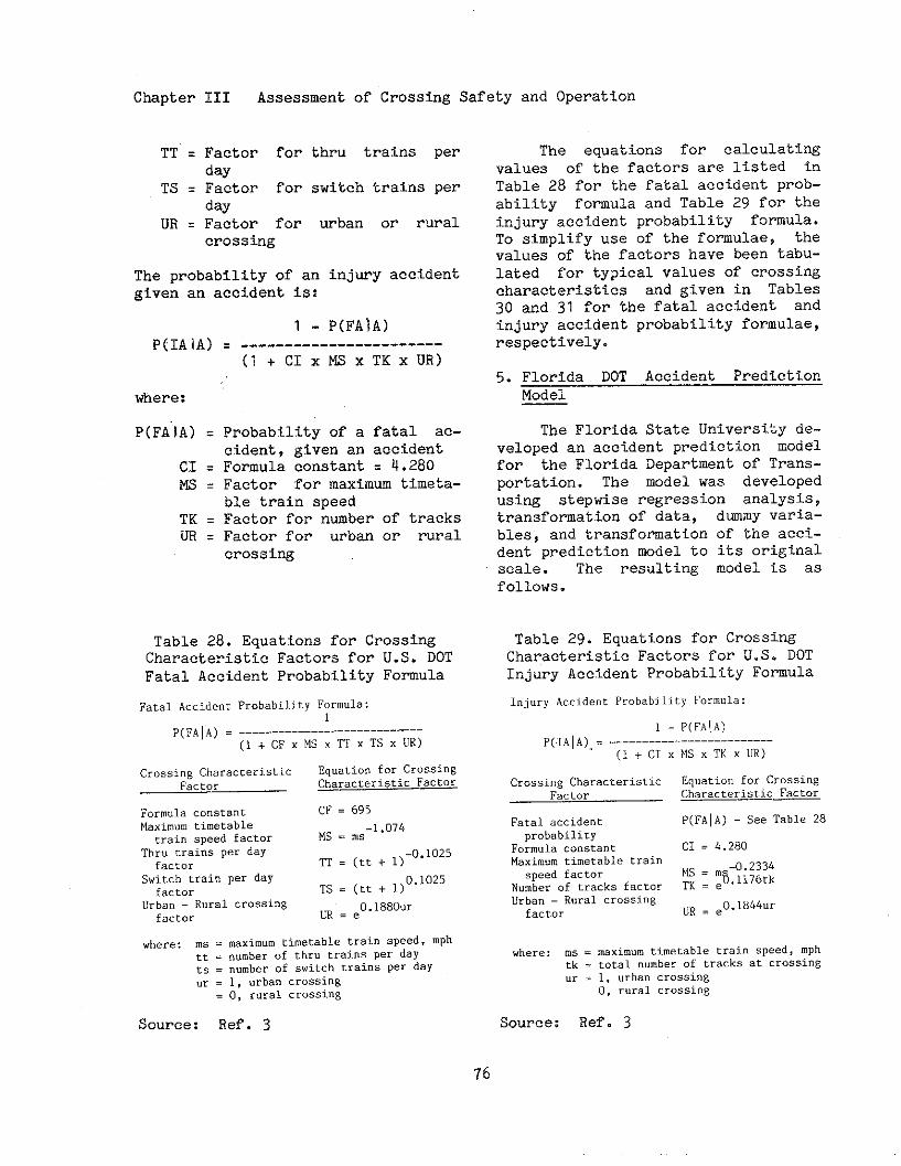
Chapter III Assessment of Crossing Safety and Operation
TT = Factor for thru trains perday
TS = Factor for switch trains perday
UR = Factor for urban or ruralcrosstig
The probability of an injury accidentgiven an accident is:
P(IAIA)
where:
P(FA’IA)=
CI =MS =
TK =UR =
1- P(FA]A)= -----------------------
(l+ CIx~x TKx UR)
Probability of a fatal ac-cident, given an accidentFormula constant = 4.280Factor for maximu timeta-ble train speedFactor for nmber of tracksFactor for urban or ruralcrossing
Table 28. Equations for CrossingCharacteristic Factors for U.S. DOTFatal Accident Probability Fomula
FatalAccidentProbabilityFormula:1
P(FAIA)= ---------------------------(I+cFx MS XTTXTSXUR)
CrossingCharacterl.stic EquationforCrossingFa’tor CharacteristicFactor
Formulaconstant CF = 695Maxim”.timetabletrainspeedfactor MS= ms-’.074
Thr” trainsper dayfactor m=(tt+l)
-0.1025
Suit.htrainper dayfactor TS = (tt+ 1)
0.1025
urban– Ruralcrossing ~R = ,0.1880..factor
where: ms = maximum timetable train speed,mphtt = numberof thrutrainsper dayts = ““mherof switchcr.i”sper day.r = 1, “rba”crossing
= o, ruralcrossing
Source: Ref. 3
The equations for calculatiWvalues of the factors are listed inTable 28 for the fatal accident prob-ability fomula and Table 29 for theinjury accident probability formula.To simplify use of tbe fomulae, thevalues of the factors have been tabu-lated for typical values of crossingcharacteristics and given in Tables30 and 31 for the fatal accident andinjury accident probability fomulae,respectively.
5. Florida DOT Accident PredictionModel
The Florida State University de-veloped an accident prediction modelfor the Florida Department of Trans-portation. The mdel was developedusing stepwise regression analysis,transformation of data, dwmy varia-bles, and transformationof the acci-dent prediction mdel to its originalscale. The resulting model is asfollows.
Table 29. Equations for CrossingCharacteristic Factors for U.S. DOTInjury Accident Probability Fomula
I“j”ry Accident Probability Form”la:
1 - P(FA\A)
P(:IA IA),,= . . . . . . . . . . . . . . . . . . . . . . .._
(l+ CIXMSXTKXUR)
Crossing Characteristic Equation for Crossing
Factor Characteristic-
Fatal accident P(FAIA) - See Table 28
probability
Form”la constant CI = 4.280
Maximum cimet.ble train
speed factOr MS = ~~~~i~~k
Numberof tracksfactor TK=eurban– Ruralcrossingfactor
“R = ,0.1844”.
where: m. = maxim”. timetable train speed,mphtk = total“umberof tracksat crossing.r . 1, urbancross,ng
O, ruralcrossing
Source: Ref. 3
76
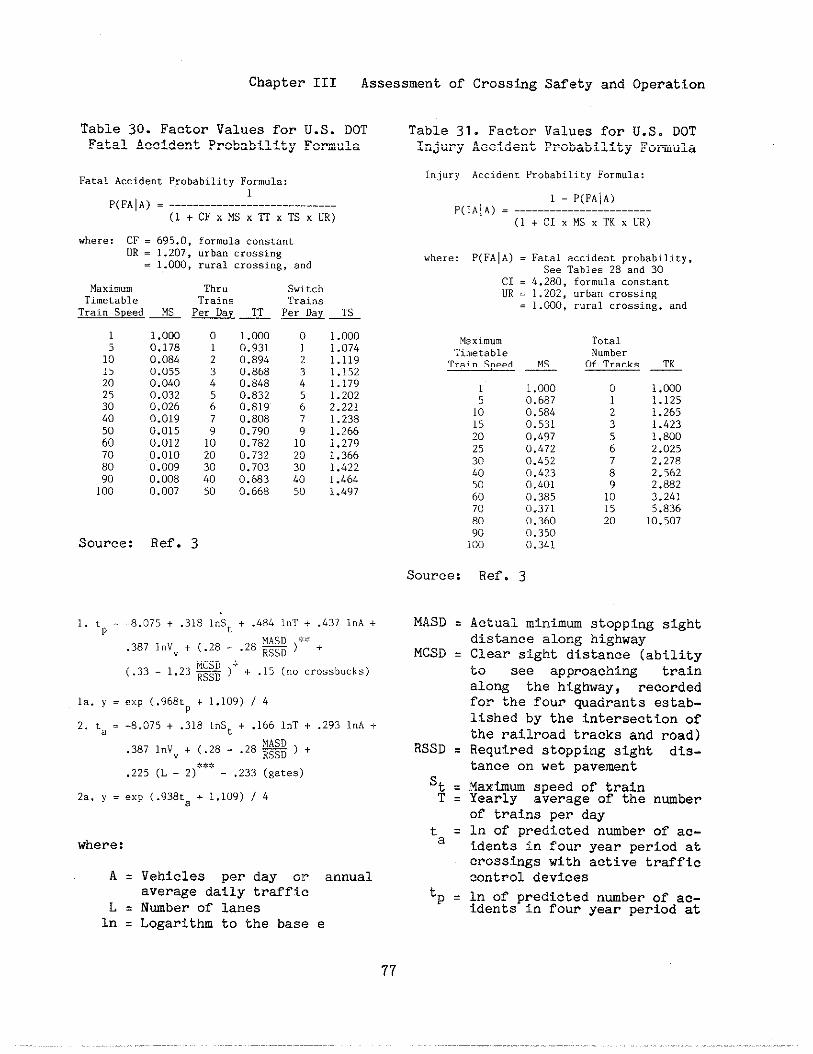
Chapter III Assessment of Crosstig Safety and Operation
Table 30. Factor Values for U.S. DOTFatal Accident Probability Formula
FatalAc.ide”tProbabilityF.rm”l.:
P(FAIA) = -------------!--------------(l+ CFXMSXTTXTSXUR)
where: CF = 695.0,formulaconstant
UR = 1.207,urban cros*i”g
= 1.000, rural crossing, a“d
Maximum Thru Switch
Timetable Trains TraifisTrainSpeed~ Per Day ~ Per Day TS
151015202530405060
1.000 0 1.000 00.178 1 0.931 10.084 2 0.894 20.055 3 0.868 30.040 4 0.848 40.032 5 0.832 50.026 6 0.819 60.019 7 0.808 70.015 9 0.790 90.012 10 0.782 10
70 0.010 20 0.732 2080 0.009 30 0.703 3090 0.008 40 0.683 40100 0.007 50 0.668 50
Source: Ref. 3
1.0001.0741.1191.1s21.1791.2022.2211.2381.2661.2791.3661.4221.4641.497
1. t,,=
la. y =
2. ta =
2a. y =
-8.075+ .3181.S,+ .484l“T+ .437l“A+
.387lnV + (.28- .28~ )*:X+v
(.33- 1.23- ):$+ .15 (“. crossbucks)
exp (.968LP + 1.1OY)/ 4
-8.075+ .318l.St+ .166lnT + .2931.A +
.387lnVv+ (.28- .28- ) +
.225(L - 2)***- .233(gates)
exp (.938ta+ 1.109)/ 4
where:
A = Vehicles per day or annualaverage daily traffic
L = Nmber of lanesin = Logarithm to the base e
Table 31. Factor Values for U.S. DOTInjury Accident Probability Fomula
I.”j”.y Accident Probabili ty Form”la:
1 - P(FA]A)
P(IA\A) = -----------------------
(l+ CIXMSXTKXUR)
where: P(FAIA) = Fatal accident probability,
See Tables28 a“d 30CI = 4.280,formulaconstant
UR = 1.202,urban crossing
= 1.000, rural crossing, a“d
Maxi.”mTi”,etableTrainSpeed &
1 1.0005 0.68710 0.58415 0.53120 0.49725 0.47230 0.45240 0.42350 0.401
Source:
~SD =
MCSD ❑
RSSD ❑
St =T=
t=a
‘P =
60 0.38570 0.37180 0.36090 0.350100 0.341
Ref. 3
TotalNumberOf Tracks ~
o 1.0001 1.1252 1.2653 1.4235 1.8006 2.0257 2.2788 2.5629 2.88210 3.24115 5.83620 10.507
Actual minimm stopping sightdistance along highwayClear sight distance (abilityto see approaching trainalong the highway, recordedfor the four quadrants estab-lished by the intersection ofthe railroad tracks and road)Required stopping sight dis-tance on wet pavement
Maximm speed of trainYearly average of the nwberof trains per dayIn of predicted nwber of ac-tdents in four year period atcrossings with active trafficcontrol devices
In of predicted nmber of ac-idents in four year period at
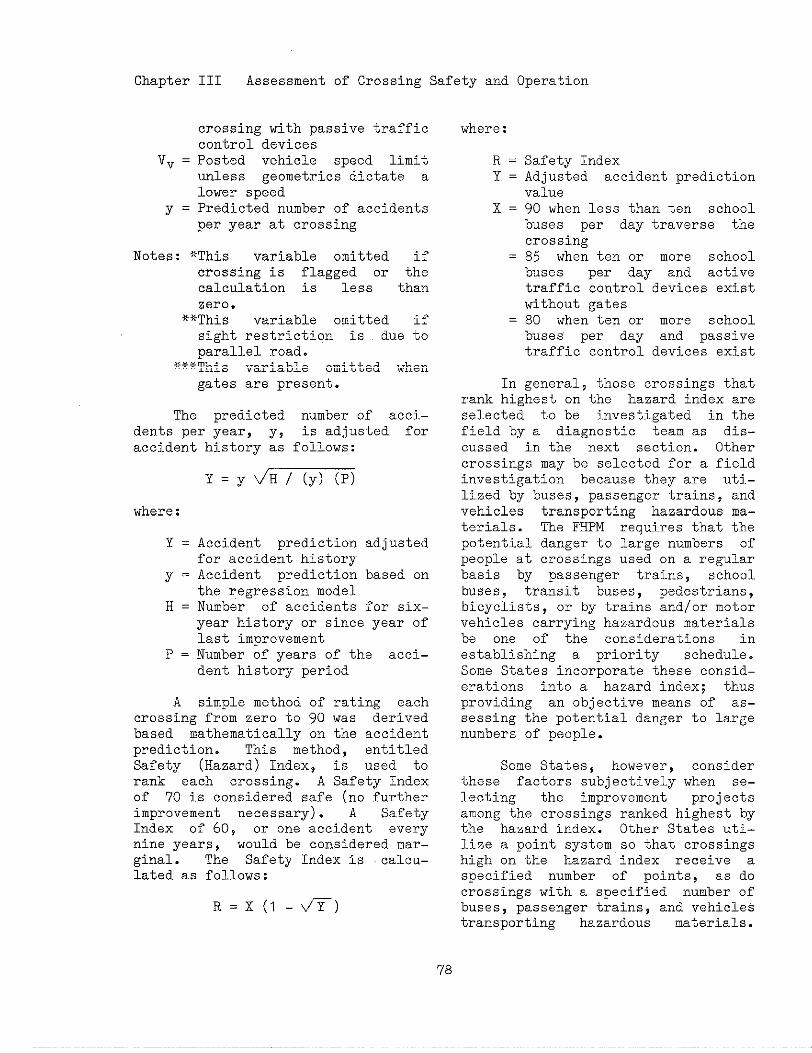
Chapter III Assessment of Crossing Safety and Operation
crossing with passive trafficcontrol devices
Vv = Posted vehicle speed limitunless geometries dictate alower speed
y = predicted number of accidentsper year at crossing
Notes: *This variable omitted ifcrossing is flagged or thecalculation is less thanzero.
**This variable omitted ifsight restriction is due toparallel road.
Y,+f*Thisvariable omitted whengates are present.
The predicted number of acci-dents per year, y, is adjusted foraccident history as follows:
Y=ytiH /(y)(P)
where:
Y = Accident prediction adjustedfor accident history
Y = Accident prediction based onthe regression model
H = Number of accidsnts for six–year history or since year oflast improvement
P = Number of years of the acci-dent history period
A simple method of rating eachcrossing from zero to 90 was derivedbased mathematically on the accidentprediction. This method, entitledSafety (Hazard) Index, is used torank each crossing. A Safety Indexof 70 is considered safe (no furtherimprovement necessary). A SafetyIndex of 60, or one accident everynine years, would be considered mar-ginal. The Safety Index is calcu-lated as follows:
R= X(l-ti~)
where:
R = Safety IndexY = Adjusted accident prediction
valueX = 90 when less than ten school
buses per day traverse thecrossing
= 85 when ten or more schoolbuses per day and activetraffic control devices existwithout gates
= 80 when ten or more schoolbuses’ per day and passivetraffic control devices exist
In general, those crossings thatrank highest on the hazard index areselected to be investigated in thefield by a diagnostic team as dis-cussed in the next section. Othercrossings may be selected for a fieldinvestigation because they are uti-lized by buses, passenger trains, andvehicles transporting hazardous ma-terials. The FHPM requires that thepotential danger to large numbers ofpeople at crossings used on a regularbasis by passenger trainsp schoolbuses, transit buses, pedestrians,bicyclists, or by trains and/or motorvehicles carrying hazardous materialsbe one of the considerations inestablishing a priority schedule.Some States incorporate these consid-erations into a hazard index; thusproviding an objective means of as-sessing the potential danger to largenumbers of people.
Some States, however, considerthese factors subjectively when se-lecting the improvement projectsamong the crossings ranked highest bythe hazard index. Other States uti-lize a point system so that crossingshigh on the hazard index receive aspecified number of points, as docrossings with a specified number ofbuses, passenger trains, and vehiclestransporting hazardous materials.
78
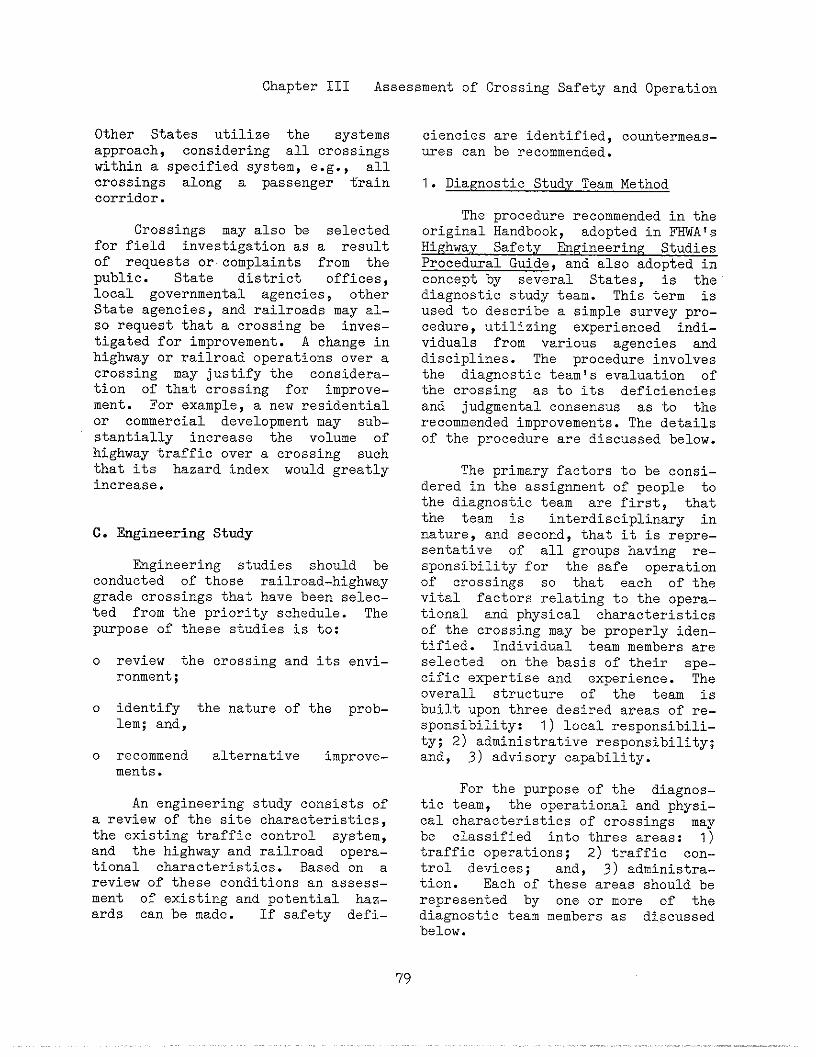
Chapter III Assessment of Crossing Safety and Operatio]~
Other States utilize the systemsapproach, considering all crossingswithin a specified system, e.g., allcrossings along a passenger traincorridor.
Crossings may also be selectedfor field investigation as a resultof requests or.complaints from thepublic. State district offices,local governmental agencies, otherState agencies, and railroads may al-so request that a crossing be inves-tigated for improvement. A change inhighway or railroad operations over acrossing may justify the considera-tion of that crossing for improve-ment. For example, a new residentialor commercial development may sub-stantially increase the volume ofhighway traffic over a crossing suchthat its hazard index would greatlyincrease.
C. Engineering Study
Engineering studies should beconducted of those railroad-highwaygrade crossings that have been selec-ted from the priority schedule. Thepurpose of these studies is to:
0
0
0
a
review the crossing and its envi-ronment;
identify the nature of the prob-lem; and,
recommend alternative improve-ments.
An engineering study consists ofreview of the site characteristics,
the existing traffic control system,and the highway and railroad Opera-tional characteristics. Based on areview of these conditions an assess-ment of existing and potential haz-ards can be made. If safety defi-
ciencies are identified, couutermeas.-ures can be recommended.
1. Diagnostic Study Team Method
The procedure recommended in theoriginal Handbook, adopted in FNA !;~
-Y Safety Engineering StudieLProcedural Guide, and also adopted inconcept by several States~ is th,?diagnostic study team. This term i~~used to describe a simple survey proc-edure, utilizing experienced indiv-iduals from various agencies anddisciplines. The procedure involvesthe diagnostic team!s evaluation
deflc~encl~~the crossing as to its . . .and judgmental consensus as to therecommended improvements. The detailf;of the procedure are discussed below,
The primary factors to be consid-ered in the assignment of people tothe diagnostic team are first, thatthe team is interdisciplinary innature, and second, that it is repres-entative of all groups having re..sponsi”bilityfor the safe operationof crossings so that each of thevital factors relating to the opera--tional and physical characteristicsof the crossing may be properly iden--tified. Individual team members arc]selected on the basis of their spe--cific expertise and experience. The?overall structure of the team isbuilt upon three desired areas of re--sponsibility: 1) local responsibili--ty; 2) administrative responsibility;and, 3) advisory capability.
For the purpose of the diagnos--tic team, the operational and physi--cal characteristics of crossings maybe classified into three areas: 1~traffic operations; 2) traffic con-.trol devices; and, 3) administra..tion. Each of these areas should bc?represented by one or more of thediagnostic team members as discussedbelow.
?9
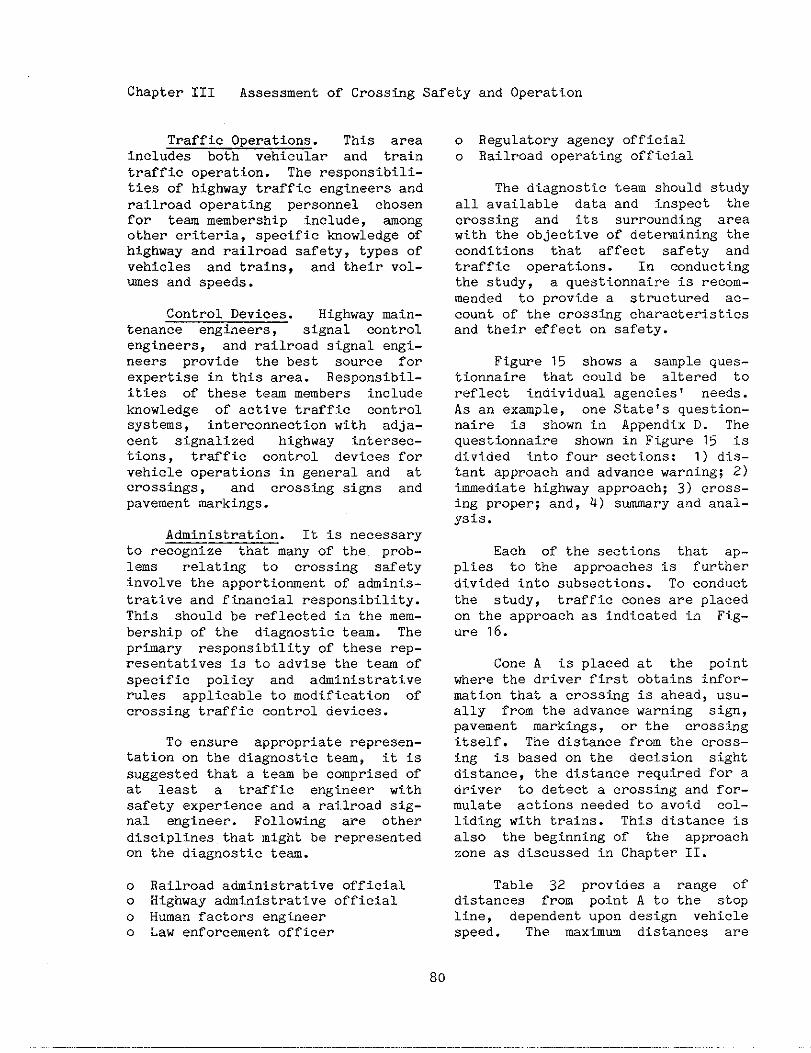
Chapter III Assessment of Crossing Safety
Traffic Operations. This areaincludes both vehicular and traintraffic operation. The responsibili-ties of highway traffic engineers andrailroad operating personnel chosenfor team membership include, amongother criteria, specific tiowledge ofhighway and railroad safety, types ofvehicles and trains, and their vol-wes and speeds.
Control Devices. Highway main-tenance engtieers, signal controlengineers, and railroad signal engi-neers provide the best source forexpertise in this area. Responsibil-ities of these tem members includeknowledge of active traffic controlsystems, interconnectionwith adja-cent signalized highway intersec-tions, traffic control devices forvehicle operations in general and atcrosstigs, and crossing signs andpavement markings.
Administration. It is necessaryto recognize that many of the prob-lems relating to crossing safetyinvolve the apportionment of adminis-trative and financial responsibility.This should be reflected in the mem-bership of the diagnostic team. Theprimary responsibility of these rep-resentatives is to advise the team of
specific policy and atiinistrativerules applicable to modification ofcrossing traffic control devices.
To ensure appropriate represen-tation on the diagnostic team, it issuggested that a team be comprised ofat least a traffic engineer withsafety experience and a railroad sig-nal engineer. Following are otherdisciplines that might be reDresentedon
0
0
0
0
th~ diagnostic t~m. “
Railroad administrative officialHighway administrative officialHuman factors engineerLaw enforcement officer
0
0
and Operation
Regulatory agency officialRailroad operating official
The diagnostic team should studyall available data and inspect thecrossing and its surrounding areawith the objective of determining theconditions that affect safety andtraffic operations. In conductingthe study, a questionnaire is recom-mended to provide a structured ac-count of the crosstig characteristicsand their effect on safety.
Figure 15 shows a sample ques-tionnaire that could be altered toreflect individual agencies’ needs.As an exaple, one State’s question-naire is shown in Appendix D. Thequestionnaire shown in Figure 15 isdivided into four sections: 1) dis-tant approach and advance warning; 2)immediate highway approach; 3) cross-ing proper; and, 4) s-ry and anal-ysis.
Each of the sections that ap-plies to the approaches is furtherdivided into subsections. To conductthe study, traffic cones are placedon the approach as indicated in Fig-ure 16.
Cone A is placed at the pointwhere the driver first obtains infor-mation that a crossing is ahead, usu-ally from the advance warning sign,pavement markings, or the crossingitself. The distance from tinecross-ing is based on the decision sightdistance, the distance required for adriver to detect a crossing and for-mulate actions needed to avoid col-liding with trains. This distance isalso the beginning of the approachzone as discussed in Chapter II.
Table 32 provides a range ofdistances from point A to the stopline, dependent upon design vehiclespeed. The maximm distances are
80
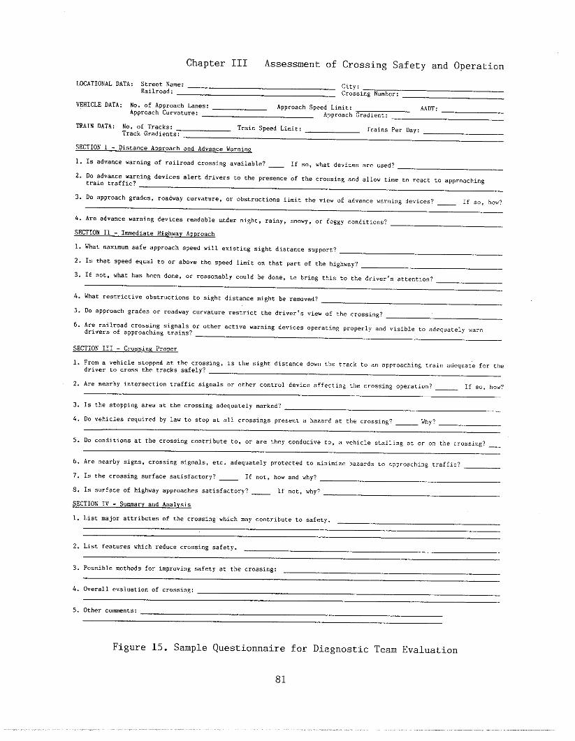
Chapter III Assessment of Crossing Safety and Operaticn
~ATIONAL DATA: Street Name:Railroad:
City:
Crassi”g Number:—
VEHICLE DATA : No. of ADProach h.,,:
—
Approach Speed Limit:Approach Curvature:
AADT :
APPr.ach Gradient:—
—
~AIN DATA: No. of Tracks: Train Speed Limit: Trains Per Day :Track Gradients:
—
—
sECTION 1 - Distance APDreach a“d Advance warning
1. 1s advance warning of railro.d crossing available? _ If so, what devices are used? —
2. Do advance warnin8 devices alert drivers LO the presence of the cros,i”g a“d al low time to react to .ppro.chi”g
train traffic?
3. Do apP,oach grades, roadway turvat”re , or obstructions limit che vie” of advance warning devices? _ If s., ho,, ?
—
h. Are advance warning devices readable under night, rainy, snowy, or fo~~y co”ditio”s?
SECTION 11 - Imediate High”ay ADDroach
—
1. What maximum safe approach speed “ill existing sight distance *.pport?
2. Is that speed equal to or above the speed limit o“ that part of the highwey?
3. If“o,,whathasbee”d.”,, 0.,easO”ably,.”ldbed.”.,t. bring this to the dri.er, s atte”ti o”?
4. What restrictive ob~tr”ctio”s to $ight distance mi8ht be removed?
5. Do approach grades or roadway curvature restrict the driver >s view of the crossing?
6. Are railroad crossing signals or other active .ar”i”g device* operating properly a“d visible co adequately war”drivers of appr.aching tra.”s?
SEmlON 111 - Crossi”E~
1. From a vehicle stopped at the crossi”e, IS the si8ht distance down the track to an approaching train adeq”at”e for the
driver to cross the tracks safely?
2. Are nesrby intersection traffic si8n.ls or other cOntrol deice affecti. ~ the cr.ssin8 OPerat iOn? _ If so, ho”?
3. 1s the stoppl”g area at the crossing adequately marked?
4. DO vehicles required by la” to stop at all crossi.8s Present a hazard at the crossina? _ why?
5. Do co”ditlons at the crossi”~ ..”tribute to, or are they co”d.cive co, a vehicle stalling at or o. the crossing? __
6. Are nearby signs, crossing si8”a1s, etc. adeq.etelyProtectedt..i.i.i..hazardst.aPPrOach$.atraffi.?_-
7. 1s the crossing surface satisfactory? _ If “at. ho” and why?
8. 1s surface of highway approaches satisfactory? _ If not, why?
SECTION IV - S.mar? and A“alysi*
1. List major attributes of the crossing which may co”trib. te to .afety.
2. List, features which reduce crossing safety.
3. Possible “ethods for improving safety at the crossi”8:
4. Overall eval.atio” of crossi”~:
5. Other come”,,:
Figure 15. Sample Questionnaire for Diagnostic Team Evaluation
81
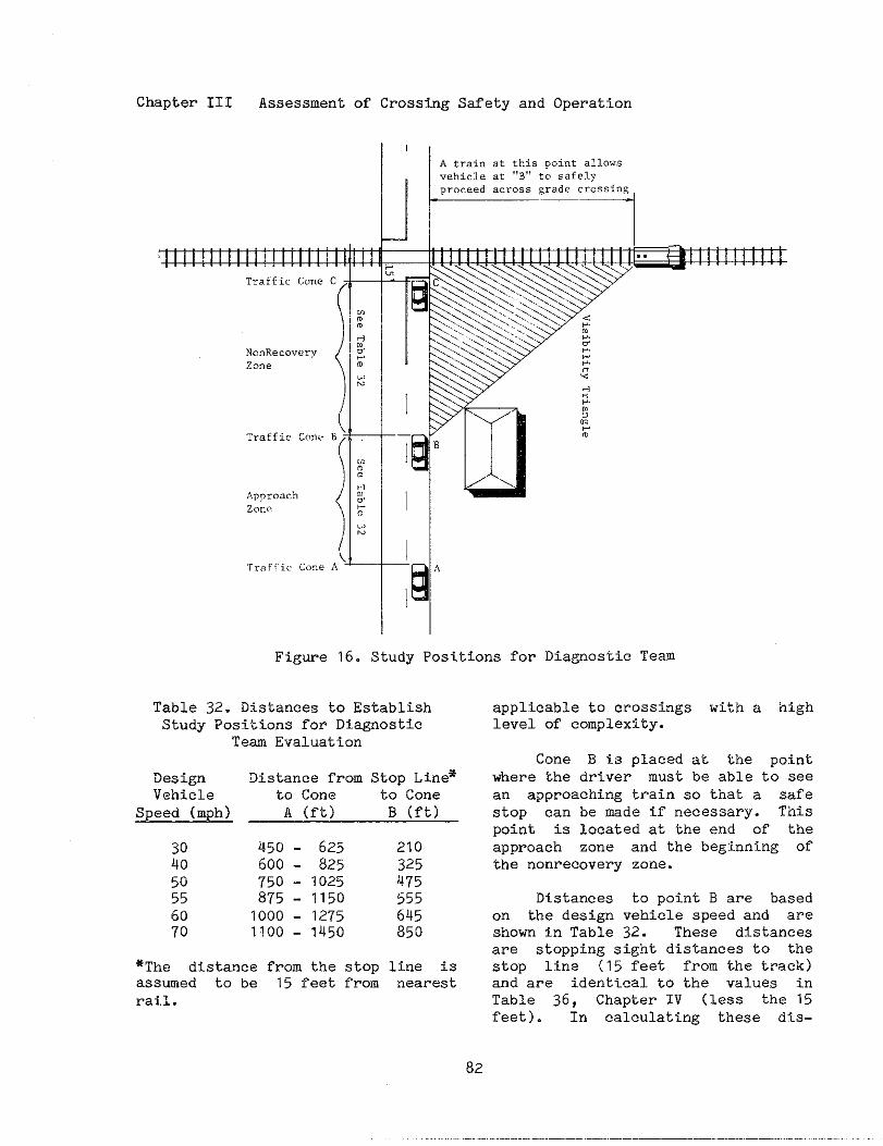
Chapter III Assessment of Crosstig Safety and Operation
Iiiiiiiiiil
TrafficCO”.C
(
N“”Reco”eryz.”.
TrafficCone
IL--A train at this point allow.
vehicle at ,, B,% to safely
prOc-ed a.rOss grad. crOssing
7
I
I--Q A
Figure 16. Study Positions for Diagnostic Team
Table 32. Distances to EstablishStudy Positions for Diagnostic
Te= Evaluation
Design Distance from Stop Line*Vehicle to Cone to Cone
Speed (mph) A (ft) B (ft)
450 - 625 210:; 600 - 825 32550 750 - 1025 47555 875 - 1150 55560 1000 - 1275 64570 1100 - 1450 850
*The distance from the stop line isassumed to be 15 feet from nearestrail.
applicable to crossings with a highlevel of complexity.
Cone B is placed at the pointwhere the driver must be able to seean approaching train so that a safestop can be mde if necessary. Thispoint is located at the end of theapproach zone and the beginning ofthe nonrecovery zone.
Distances to point B are basedon the design vehicle speed and areshown in Table 32. These distancesare stopping sight distances to thestop line (15 feet from the track)and are identical to the values inTable 36, Chapter IV (less the 15feet). In calculating these dis-
82
Chapter III Assessment of Crossing Safety and Operation
tances, a level grade is asswed. Ifthis is not the case, an allowanceshould be mde for the positive ornegative effects of grade.
Cone C is placed at the stopline, assumed to be 15 feet from thenearest rail.
The questions in Section I ofthe questionnaire (Figure 15) areconcerned with the fOllowing.
0
0
0
0
Driver awareness of the crossing
Visibility of the crossing
Effectiveness of advance warning
signs and signals
Geometric features of the highway
Men responding to questions in thissection, the crosstig should be ob-served at the beginning of the ap-proach zone, the location of trafficcone A.
The questions in Sectfon II areconcerned with whether or not thedriver has sufficient information todetect an approaching train and makecorrect decisions about crossingsafely. Observations for respondingto questions in this section shouldbe made from cone B. Factors consid-ered by these questions include thefollowing.
o Driver awareness of approachingtrains
o Driver dependence on crossing sig-nals
o Obstruction of view of train ap-proach
o Roadway geometries diverting driv-er attention
0 Potential location of standingrailroad cars
o Possibility of removal of sightobstructions
o Availability of information fOrproper stop or go decisions bythe driver
The questions in Section IIIaPPIY tO observations adjacent to thecrOssing, i.e. cone C. Of particularconcern, especially when the drivermust stop, is the ability to see downthe tracks for approaching trains.Also, intersecting streets and drive-ways should be observed to deteminewhether intersecting traffic couldaffect the operation of highway vehi-cles over the crossing. Questions inthis section relate to the following.
0
0
0
0
0
0
Sight distance down the tracks
Pavement markings
Conditions conducive to vehiclebeconing stalled or stopped on thecrosstig
Operation of vehicles required bylaw to stop at crossing
Signs and signals as fixed objecthazards
Opportunity for evasive action bythe driver
In Section IV of the question-naire the diagnostic team is giventhe opportunity to do the following.
o List major features that contrib-ute to safety
o List features that reduce crossingsafeky
83
Chapter III Assessment of Crossing Safety and Operation
0 Suggest methods for improvingsafety at the crossing
o Give an overall evaluation of thecrossing
o Provide comments and suggestionsrelative to the questionnaire
In addition to completing thequestionnaire, team members shouldtake photographs of the crossing fromboth the highway and the railroadapproaches.
Current and projected vehiclead train operation data should beobtained from the team members. In-formation on the use of the crossingby buses, school buses, trucks trans-porting hazardous material and pas-senger trains should be provided.The evaluation of the crossing shouldinclude a thorough examination of ac-cident frequency, accident types, andaccident circumstances. Both train-vehicle accidents and vehicle-vehicleaccidents should be examined.
Team members should drive each
apprOach several times tO become fa-miliar with all conditions that existat, or near, the crossing. All traf-fic control devices (signs, signals,markings, and train detection cir-cuits) should be examined as part ofthis evaluation. If the crossing isequipped with signals, the railroadsignal engineer should activate themso that their alignment and lightintensity may be observed.
Two principal references to beused for this evaluation are theMnual on Uniform Traffic Control De-vices and the Traffic Control DevicesHandbook. Also, A User!s Guide toPositive Guidance provides informa-tion for conducting evaluations oftraffic control devices.
After the questionnaire has beencompleted, the team is reassembledfor a short critique and discussionperiod. Each member should summa-rize his observations pertaining tosafety and operations at the cross-ing. Possible improvements to con-sider include the following.
0
0
0
0
Closing of crossing -- Availablealternate routes for highway traf-fic.
Site Improvements -- Removal ofobstructions in the sight trian-gle, highway realignment, improvedcross section, drainage, or illu-mination.
Crossing Surfaces -- Rehabilita-tion of the highway structure, thetrack structure, or both. Instal-lation of drainage and subgradefilter fabric.
Traffic Control Devices -- Instal-lation of passive or active cOn-trol devices and improvement oftrain detection equipment.
The results and recommendationsof the diagnostic team should be doc-umented, Recommendations should bepresented promptly to programming andimplementationauthorities.
2. Other Engineering Studies
In addition to the factors men-tioned abo,vethere are other consid-erations to complete a comprehensiveexamination of a crossing. These arebriefly described below.
Traffic Flow Operations. Impor-tant considerationsfor traffic flowoperations are the traffic volume(daily and peak how), the mix of ve-hicle types, their operating speeds,the capacity of the road, delays, and
84
Chapter III
queue lengths. These should beviewed in terms of their statushow they might be affected by
Assessment of Crossing Safety and Operation
re-andim-
provemen~s at-the crossing. Tw~ par-ticular concerns are access acrossthe railroad by emergency vehiclesand the uss of the crossing by spe-cial vehicles, i.e. trucks transport-ing hazardous material and buses.Standard data collection proceduresfor evaluating these factor; are con-tained in FWA Js Highway Safet3~Engi-neering Studies, Procedural Guide orin the Institute of TransportationEngineer’s Manual of Traffic Engi-neering Studies.
Commwity Separation. The engi-neering field survey should also con-sider the impacts of crossing opera-tions on the commmity. Considera-tions include frequency and type oftrain operations, pedestrian and bi-cycle access, and number of crossingsin the commmity needed to provideadequate vehicle access.
D. The Systems Approach
The procedures for evaluatingrailroad-highway grade crossings aregenerally based upon the physical andoperational characteristics of indi-vidual crossings. A typical crossingsafety program consists of a numberof individual crossing projects.Finding for crossing safety is ap-proved on the basis of the require-ments of these individual projects.Therefore, crossing evaluation, pro-gramming, and construction followstraditional highway project implemen-tation procedures.
The concept of using the systemsapproach tO railroad - highway gradecrossing improvements was etiancedwhen crossings off the Federal-aidsystem were made eligibls for Feder-ally fuuded programs. Since all pub-
lic crossings are now eligibls forimprovement with Federal funds, thesystems approach provides a compre-hensive method for addressing safetyand operations at crossings.
The systems approach considersthe railroad-highway grade crossingto be a part, or a component of, alarger transportation system. Forthis purpose, the transportation sys-tem is defined as a land surface sys-tem consisting of both highway andrailroad facilities. The intersec-tion of these two transportationmodes affects both safety and opera-tions of the entire system. Theobjective of the systems approach forcrossings is to improve both safetyand operations of the total system orsegments of the system.
The systems approach may beapplied to a segment of the rail com-ponent of the system. For example, toimprove operating efficiency andsafety over a specified segment of arail line, all crossings would beconsidered in the evaluation. Thus,the systems approach is often calledthe corridor approach. Or, the sys-tems approach may be applied to anurban area, city, or commmity. Inthis case, all public crossings with-in the jurisdiction of a public agen-cy are evaluated and programmed forimprovements. The desired outcome isa combination of engineering improve-ments and closures such that bothsafety and operations are highlyimproved.
Assume that a segment of railline is to be upgraded for mit trainoperations or high speed passengerservics. This type of change in railoperations would provide an idsal op-portunity for the application of thesystems approach. Ths rail line maybe upgraded by track and signal im-provements for train operations that
85
Chapter III Assessment of Crossing Safety and Operation
might cause a need for adjustments intrain detection circuits of activetraffic control devices. Also, modi-fications of train operations andspeeds may require the installationof active traffic control devices atselected crossings.
A system approach developed for
crossings in a specified commmity or
political subdivision allows for a
comprehensive analysis of highway
traffic operations. Thus , unnece-
ssary crossings can be closed and
improvements made at other crossings.
This approach enhances the accepta-
bility of crossing closures by local
officials and citizens.
Initially, all crossings in thesystem, both public and private,
should be identified and classified
by jurisdictional responsibility,
e.g. city, Comty, and State for
public crossings, and parties to the
agreement for private crossings. In-
formation should be gathered on high-
way traffic patterns, train Opera–
tions, emergency access needs, land
uses, and growth trends. The inven–
tory records for the crossings should
be updated to reflect current opera-
tional and physical characteristics.
A diagnostic team, consisting of rep-
resentatives from all of the public
agencies having jurisdiction over the
identified crossings and the rail-
roads operating over the crossings,should make an on-site assessment ofeach crossing as described in theprevious section. The diagnosticteam!s recommendations should consid-er, among other things, crossing clo-sure, installation of active trafficcontrol devices, upgrading existingactive devices, elimination by gradeseparation, surface improvements~ andimprovements in the train detectioncircuits. In addition, modificationof train operations near, and at,
each crossing, removal of sight ob-structions, rerouting of specialvehicles and emergency vehicles, andrailroad relocation should be consid-ered.
Federal, State, and local cross-ing funding programs should be re-viewed to identify the eligibility ofeach crossing improvement for publicfunding. Other funding sources in-clude railroads, urban renewal finds,land development funds, and otherpublic or private funding sources.
There are several advantages ofthe systems approach. A group Of
crossings may be improved more effi-ciently through the procurement ofmaterials and equipment in quantity,thus reducing product procurement andtranspOrtatiOn costs. Usually, onlyone agreement between the State,local jurisdiction, and railroad isnecessary for all of the improve-ments. Train detection circuits maybe designed as a part of the totalrailroad signal system rather thancustom designed for each individualcrossing. Electronic components,relay houses, and signal transmissionequipment may be more efficientlyutilized. Labor costs may be si~if-icantly reduced. Travel time of con-struction crews may be reduced whenprOjects are in close proximity ofeach other.
Railroads benefit from the ap-plication of the systems approach inseveral ways. Train speeds may beincreased due to safety improvementsat crossings. Maintenance costs maybe reduced if a sufficient number ofcrossings are closed. Other improve-ments may efiance the efficiency ofrail operations.
Safety improvements are an obviousbenefit to the public. Other bene-
86
Chapter III Assessment of Crossing Safety and Operation
fits include reduced vehicular de-
lays and better access for emergency
vehicles.
One impediment to the systems
approach is that most Federal and
State crossing safety improvement
programs provide funding for safety
improvements only. Also, safety im-
provement pro jects may be limited to
crossings that rank high on a prior-
ity schedule. Another impediment is
the involvement of multiple jurisdic-
tions.
The Federal Highway Administra-
tion (FHWA) has endorsed the systems
aPProach and its resultant identifi-
cation of low-cost improvements to
crossing safety and operations. The
FHWA has sponsored a demonstration
project that utilized the systems
approach to improve crossings along arail corridor in Illinois.
In order to eliminate the need
for pro ject agreements with each
local agency, the Illinois CommerceCommission issued a single order cov-ering the work to be performed atnine locations. This accelerated theproject and reduced labor intensivework. The FRWA and the IllinoisDepartment of Transportation (DOT)agreed that minimal plan submittalswould be required of the local agen-cies, and the local agencies agreedto perform the necessary work atmutually agreed upon lump sum pricesmder the supervision of Illinois DOTdistrict representatives.
Improvements made as part of thedemonstration project in Illinoisincluded the following.
o Removal of vegetation
o Pavement widening
o Reconstruction of approaches
o Installation of 12-inch lenses incrossing signals
o Relocation of train loading areas
0 Closure of crossings
o Removal of switch track
o Installation of traffic controlsi~s pertinent to crossing geo-metric
The Florida Department of Trans-portation (DOT) and other States haveadopted policies incorporating thesystems approach as a part of theircrossing safety improvement programs.The Florida DOT selects track seg-ments on the basis of the followingconditions.
0
0
0
0
E.
1.
Abnormally high percentage ofcrossings with passive trafficcontrol devices only
Freight trains carrying hazardousmaterial in an environment thatpresents an unacceptable risk of acatastrophic event
Passenger train routes
Plans for increased rail traffic,especially commuter trains
References
Box, Paul C. and Oppenlander, J.C.Manual of Traffic Engineering Stud-=, Washington, DC: Institute ofTransportation Engineers, 1976.
2. Code of Federal Regulations, TitleQ, Washington, DC: Superintendentof Documents, Government Printing Of-fice, published annually.
3. Farr, E.H. and J.S. Hitz, AccidentSeverity Prediction Formula for Rail-

Chapter III Assessment of Crossing Safety and Operation
Highway Crossings, Washington, DC: 12. Schoppert, David W. and Dan W.Federal Highway Administration, Fed- Hoyt, Factors Influencing Safety ateral Railroad Administration, Report HiEhway-Rail Grade Crossings, Wash-FHWA-RD-83/092, JUIY 1983. ington, DC: Highway Research Board,
NCHRP Report 50, 1968.4. Federal-Aid Highway Program Manu-g, Washington, DC: Federal Highway 13. Traffic Control Devices Handbook,Administration, updated periodically. Washington, DC: Federal Highway Ad-
ministration, 1983.5. Federal Highway AdministrationSurvey of Region and Division Of- 14. Update Ma.nl]a.l: Nat.ional Rai 1road
fices, unpublished 1984. Highway Cros:–..~_...-...ton, DC: U.S. Departm,
6. GOOdell - Grivas, Inc., Highway portation, 1976.
---------sin. Tnvent~, Washing-
Ientof Trans-
Safety Engineering Studies, Procedur-&Guide, Washington, DC: Federal
Hi g—zhway Administ~ati8n. FHWA-TS-81-
226, J~ne 1981.
7. Hitz, John and Mary Cross, Rail-Highway Crossing Resource AllocationProcedure User!s Guide, Washington,DC: Federal Highway Administrationand Federal Railroad Administration,Report FHWA-IP-82-7, December 1982.
8. Manual on Uniform Traffic ControlDevices Washington, DC: Federal— 7Highway Administration, 1978, Revised1979, 1983, and 1984.
9. A Policy on Geometric Design ofHighway and Streets, Washington, DC:American Association of State Highwayand Transportation Officials, 1984.
10. Post, T.J., G.J. Alexander, andH. Lunenfeld, A Userts Guide to Posi-tive Guidance, Second edition, Wash-ington, DC: Federal Highway Adminis-tration, Report FHWA-TO-81-1, Decem-ber 1981.
11. Railroad/Highway Grade CrossingAccidents Involving Trucks Transport–ing Bulk Hazardous Materials, A Spe-cial Study, Washington, DC: NationalTransportation Safety Board., ReportNTSB-HZM-81-2, September 1981.
88
IV. IDENTIFICATION OF MTE~ATIVES
In the previous chapters, meth-odologies for selecting and analyzingpotentially hazardous railroad-htgh-way grade crossings were presented.In this chapter, alternative safetyand operational improvements are dis-cussed. These alt.ernat.ives are pre-sented by type: crossing elimination;installation of passive traffic cOn-trol devices; installation of activetraffic control dev?.ces; site im-provements; crossing surface improve-ments; and, removal of grade separa-tions. From information conta%ned inthis chapter, tinehighway engineershould select. several alternativeilnprOVementproposals for any partic-ular crossing being studied. The *vdo-nothingt! alternative should also beconsidered a proposal. Proceduresfor selecting song the variousalternatives are presented in ChapterV, Selection of Alternatives.
A. Eltiinatfon
The first alternative thatshould always be considered for arailroad-highway at-grade crossing iselimination. Elimination can be ac-complished by grade separating thecrossing, closing the crossing tohighway traffic, or closure of thecrossing to railroad traffic throughthe abandonment or relocation of therail line. Elimination of a crossingprovides the highest level of crossing safety because the point of in-tersection between highway and rail-road is removed. However, the ef-fects of elimination on highway andrailroad operations may be beneficialor adverse. Thus, the benefits of
the elimination alternative are pri-marily safety and perhaps operation-
al, offset by construction and opera-tional costs.
Decisions regarding whether thecrossing should be eliminated or oth-erwise improved through the installa-t.iOnof traffic control devices orsite or surface improvements dependsupon safety, operational, and costconsiderations. However, the FederalHighway Progrm Manual (FHPM) doesspecify that ,,allcrossings Of rail-
roads and highways at wade shall beeliminated where there is full cOn-trol of access on the highway (afreeway) regardless of the v~~me ofrailroad or highway traffic”.
The major benefits of crossingelimination include reductions in ac-cidents, reductions in highway vehi-cle delay, reductions in rail trafficdelay, and reductions in maintenancecosts of crossing surfaces and traf-fic control devices.
Safety considerations includeboth train - involved accidents andnon-train involved accidents. Cer-tain vehicles, e.g. school buses andtrucks carrying hazardous materials,may be required to stop at all cross-ings. These vehicles, that may stopunexpectedly, my cause collisionswith other vehicles. In addition,the presence of the crossing itselfmay cause non-train accidents. Forexmple, when stopping suddenly toavoid a collis%on with an oncomingtrain, a driver may lose control ofthe vehicle and collide with a road-
14Federal - Aid Highway Program
Manual, 6-6-2-1, Washington, DC:Federal Highway Atiinistration.
Chapter IV Identificationof Alternatives
side object. Thus, these types ofaccidents would be avoided if an at-grade crossing were eliminated.
Four types of delay are imposedon highway traffic by crossings.
o Delay due to trains occupyingcrossings. Highway traffic shouldslow down to look for trains, par-ticularly at crossings with pas-sive traffic control devices. Ve-hicles must stop and wait for atrain to clear a crossing. Fur-thermore, there may be some delayto vehicles which arrive at acrossing before those vehiclesthat were delayed by a train havecleared the crossing.
o Delay to special vehicles. Cer-tain vehicles may be required tostop at all crossings. These in-clude school buses, buses carryingpassengers for hire, and vehiclescarrying hazardous materials. Inaddition to the delay incurred bythese special vehicles, theirstopping may also impose delay onfollowing vehicles.
o Delay due to crossing surface.Crossing surfaces should be main-tained so that they provide asmooth surface.
o Delay due to crossing. This delayoccurs regardless of whether ornot a train is approaching or oc-cupying the crossing. Motoristsusually slow down in advance ofcrossings so that they can stopsafely if a train is approaching.In fact, this is a required safedriving practice in conformancewith the Uniform Vehicle Code,which states “...vehicles muststop within 15 to 50 feet from thecrossing when a train is in suchproximity so as to constitute an
imedi.ate hazard.”15 Therefore~the existence of a crossing maycause some delays to motorists whoslow to look for a train.
Railroads also sometimes exper-ience delays due to the presence ofcrossings, that may be alleviatedshould the crossings be eliminated.Some local jurisdictions restricttrain speeds on the basis that cross-ing accidents would be less severeshould they occur. Not only are de-lays caused by trains moving at slow-er speeds, but also because trainsare slow to accelerate back to thehigher speed. Eliminating crossingswould also reduce train delay due tocrossing accidents.
Another benefit of crossingelimination is the alleviation ofmaintenance costs of surfaces andtraffic control devices. As dis-cussed in a later chapter on mainte-nance, these costs can be quite sub-stantial for both highway agenciesand railroads.
Costs of eliminating crossingsdepend on whether the crossing ismerely closed to highway traffic, agrade separation is constructed, orthe highway or railroad is relocated.These costs are discussed along withother considerations for each type ofelimination alternative.
1. Grade Separation
The Traffic Control DevicesHandbook suggests that grade separa-tions be considered specifically in
15u~if0~~ vehicle code and Model
Traffic Ordinances, Evanston, IL:National Comittee on Unifom TraffieLaws and Ordinances, lg61, and Sup-plement, 1984.
Chapter IV Identification of Alternatives
the design of new highway routes andimprovements to railroad facilities.A grade separation is recommended forhighways that must cross high speedrailroad passenger routes.
While no Federal criteria forgrade separations exist, many Stateshave developed their own criteria orwarrants. Specific criteria providea means to justify the expenditure offunds for separating grades at somecrossings while not separating gradesat others. Obviously, costs and ben-efits should be considered Ln thedecision-making process; however, asdiscussed in Chapter V, some costsand benefits are difficult to quanti-fy. Thus, engineering judgment playsa major role in selecting the gradeseparation alternative.
A few States consider the gradeseparation alternative for a crossingif its priority index is above aspecified value. A few other Statesutilize an exposure index such thatif the product of train and highwaytraffic is above a specified value aseparation of grade is considered.
It is recommended that gradeseparations be considered as an al-ternative for heavily traveled cross-ings. However, costs and benefitsshould be carefully weighed as gradeseparations are expensive to cOn-struct and maintain. In some cases,it may be feasible to separate gradesat one crossing in a comunity ortown and close mogt of the remainingcrossings.
2. Highway and Railroad Relocation—
Other alternatives to railroad-highway grade crossing problems arerelocation of the highway or railroador railroad consolidation. These al-ternatives provide a solution to oth-er railroad impacts on comunlties;
however, the costs associated withrelocation or consolidation can bequite high.
Railroads provide advantages anddisadvantages to communities. Theygenerate emplo~ent opportunities forlocal citizens, provide transporta-tion services to local industries andbusinesses, and are a source of taxrevenue to goverment agencies. Butthe presence of railroads in commun-ities can impose some disadvantages,such as vehicular delay and safetyconcerns at railroad-highway gradecrossings. In addition, the presenceof railroads may impose noise andoVner environmental concerns upon thecomunity. Railroad relocation tothe outer limits of the c-unity maybe a viable alternative for alleviat-ing these concerns while retainingthe advantages of having railroadservice. Relocation generally in-volves the conplete rebuilding ofrailroad. facilities. Not only doesthis req,uiretrack construction, butalso acquisition of right-of-way andconstrueti.on of drainage structures,signals, communications, crossingsand separations, station facilities,and utilities.
In some cases, consolidation ofrailroad.lines into comon corridorsor joint operations over the sametrackage may allow for the removal ofsome trackage through a comunity.Railroad. consolidation may providebenefits similar to those of railroadrelocation, and possibly at lowercosts.
Benefits of railroad relocation,in addition to those associated withcrossing safety and operations, in-clude: improved environment result-ing from decreased noise and air pol-lution; improved land use and appear-ance; and, improved railroad effi-ciency. Railroad relocation and con-
91
Chapter IV Identtftcatton of Alternatives
solidation may also provide for theelimination of obstructions to emer-gency vehicles and the safer movementof hazardous materials. Collective-ly, the tangible and intangible bene-fits may justify the relocation orconsolidation of railroad facilities,whereas, any one of the benefitsalone might not provide sufficientjustification for the expense.
Many factors must be consideredin planning for railroad relocation.The new location should provide goodalignment, minimum grades, and ade-quate drainage. Sufficient right-of-way should be available to providethe necessary horizontal clearances,additional rail facilities as servicegrows, and a buffer for abating noiseand vibrations. The nmber of cross-ings should be minimized.
The railroad corridor can befurther isolated from residential andcomercial activity by zoning theproperty adjacent to the railroad aslight and heavy industrial. Busi-nesses and industry desiring railservice can locate in this area.
To accomplish a rail relocationor consolidation project, a partner-ship is required between the Federalgovernment (if Federal funds are in-volved), State and local govermentagencies, the railroad, and the com-munity. While the purpose of theproject may be only to eliminatephysical conflicts between the high-WaY user and the railroad, the part-nership developed for this projectprovides an atmosphere of cooperative
working relationships that continuesinto the future.
Highway relocations are some-times accomplished to provide im-proved highway traffic flow aroundcommunities and other developed ar-
eas. Planning for highway reloca-tions should consider routes thatwould eliminate at-grade crossings byavoidtng the need for access overrailroad trackage or by providinggrade separations.
3. Closure
Closure of a railroad-highwaygrade crossing to highway trafficshould always be considered as an al-ternative. Numerous crossings werebuilt when railroads first beganoperating. Then, safety was not aserious concern since horse drawncarriages could easily stop and trainspeeds were low.
Closure of at-grade crossings isnormally accomplished by closing thehighway. The nwber of crossingsneeded to carry highway traffic overa railroad in a comunity ts i,nflu-enced by many of the characteristicsof the comunity itself. A study ofhighway trtific flow should be con-ducted to detemine origin and desti-nation points and needed highwaycapacity. Thus, optimm routes overrailroads can be detemined. Highwayoperation over several crossings maybe consolidated to move over a nearbycrossing with flashing lights andgates or over a nearby grade separa-tion. Alternative routes should bewithin a reasonable travel time anddistance from a closed crossing. Thealternate routes should have suffi-cient capacity to accommodate thediverted traffic safely and effi-ciently.
There are several stumblingblocks to successful closure, such asnegative comunity attitudes, fundingproblems, and lack of forceful Statelaws authorizing closure or reluctantutilization of State laws that pemitclosure.
92

Chapter IV Identification of Alternatives
Legislation that authorizes a
State agency to close crossings fa-
cilitates the implementation of clo-
sures greatly. A list of State agen-
cies that have the authority to close
crossings is contained in Appendix E.
These State agencies should utilize
their authority to close crossings
whenever possible. Often, a State
agency can accomplish closure where
local efforts fail due to citizen bi-ases and fear of losing access acrossthe railroad. Local OppOsitiOn maysometimes be overcome through empha-sis on the benefits resulting fromclosure such as improved traffic flowand safety as traffic is redirectedto grade separations or crossingswith active traffic control devices.Railroads often support closure, notonly because of safety concerns, butalso because maintenance costs asso-ciated with the crossing are elimi-nated.
To assist i.n the identificationof crossings that may be closed, thesystems approach Inightbe utilized asdiscussed in Chapter 111. With thismethod, several crossings in a comu-nity or rail corridor are improved bythe installation of traffic controldevices while other crossings areclosed. This i.saccomplished follow-ing a study of traf~ic flows in thearea to assure continuing accessacross the railroad. Traffic flowsare sometimes improved by the instal-lation of more sophisticated trafficcentrol systems at the remainingcrossings and perhaps the cOnstruc-tion of a grade separatiOn at one ofthe remaining crossings.
Another important matter to con-
sider in connection with crossingclosure is access over the railroadby emergency vehicles, ambulances,fire trucks, and police. Crossingsthat are frequently utilized by emer-gency vehicles should not be closed.
On the contrary, these crossingsshould be candidates for grade sepa-rations or the installation of activetraffic control devices.
Specific criteria to identifythose crossings that should be closedare difficult to establish because ofthe nmerous and various factors thatshould be considered. The TrafficControl
—.Devices Handbook suggests
criteria that my be used for cross-ing closure. It is important thatthese criteria not be used withoutprofessional, objective, engineering,and economic assessment of the posi-tive and negative impacts of crossingclosures.
Criteria for crossings on branchlines:
o less than 2,000 ADT;
0 more than two trains per day; and,
0 alternate crossing within 0.25miles that has less than 5,000 ADTif two-lane, or less than 15,000ADT if four-lane.
Criteria for crossings on spurtracks:
o less than 2,000 ADT;
0 more than 15 trains per day; and,
0 alternate crossing within 0.25miles with less than 5,000 ADT iftwo-lane, Or less than 15,000 ADTif four-lane.
Criteria for crossing on main line:
0 any main line section with morethan five crossings within a 1.0mile segment.
When a crossing is permanentlyclosed to highway traffic, the exist-
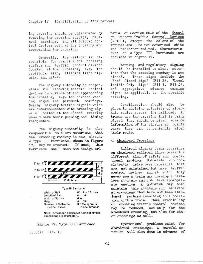
Chapter IV Identification of Alternatives
ing crossing should be obliterated byremoving the crossing surface, pave-ment markings, and all traffic con-trol devices both at the crossing andapproaching the crossing.
Generally, the railroad is re-
sponsible for removing the crossing
surface and traffic control devices
located at the crossing, e.g. the
crossbuck sign, flashin2 light sig-
nals, and gates.
The highway authority is respon-sible for removing traffic controldevices in advance of and approachingthe crossing, e.g. the advance warn-ing signs and pavement markings.Nearby highway traffic signals whichare interconnected with crossing sig-nals located at the closed crossingshould have their phasing and timingreadjusted.
The highway authority is alsoresponsible to alert motorists thatthe crossing roadway is now closed.A Type III barricade, shown in Figure17, may be erected. If used, thisbarricade shall meet the design cri-
Type III Sarticade
Wdth of Rail Vmin-l YmaxLength of Rail 4 ft. minWdth of Stripes 6 in.Height 5 ft. min
Number of Reflector- 3 if facing trafficized Rail Faces in one direction
Note For wooden barricades nominal lumberdimensions are satisfactory.
Figure 17. Type III Barricade
Source: Ref. 15
teria of Section 6c-8 of the Manualon Uniform Traffic Control Devices(~TCD), except the colors of thestripes shall be reflectorized whiteand reflectorized red. Characteris-tics of a Type III barricade areprovided in Figure 17.
Warning and regulatory signingshould be installed to alert motor-ists that the crossing roadway is nowclosed. These signs include the!!Road Closed Signll (R11-2), “LocalTraffic Only Sign!! (R11-~, RI 1-4),and appropriate advance warningsigns as applicable to the specificcrossing.
Consideration should also begiven to advising motorists of alter-nate routes across the railroad. Iftrucks use the crossing that is beingclosed they should be given advanceinformation of the C1Osure at pointswhere they can conveniently altertheir route.
4. Abandoned Crossings
Railroad-highway grade crossingson abandoned railroad lines present adifferent kind of safety and opera-tional problem. Motorists who con-sistently drive over crossings thatare not maintained but have trafficcontrol devices and at which theynever see a train may develop a care-less attitude and not take appropri-ate caution. A motorist may thenmaintain this attitude and behaviorat crossings that have not been aban-doned; perhaps resuiting in a colli-sion with a train. Thus, credibilityof crossing traffic control devicesmay be reduced, not only for theabandoned crossing, but also for oth-er crossings as well.
Operational problems exist forabandoned crossings. A careful mo-torist will slow down in advance of
94

Chapter IV Identification of Alternatives
every crossing, especially those withPassive traffic control devices. Ifthe track has been abandoned, unnec-essary delays result, particularlyfor special vehicles required by Fed-eral and State laws to stop in ad-vance of every crossing. These spe-cial vehicles include school buses,buses carrying passengers for hire,and vehicles transporting hazardousmaterials. In addition, these vehi-cles may be involved in vehicle-veili-cle collisions that occur because of
their unexpected stops.
The desirable action for aban-doned crossings is to remove alltraffic control devices related tothe crossing and to remove or paveover the tracks. The difficulty isidentifying abandoned railroad lines.For example, a railroad my discon-tinue service over a line or a track;with the possibility that anotherrailroad, particularly a short linerailroad, may later purchase or leasethe line to resme that service.These railroad lines are called inac-tive lines and, obviously, removingor paving over the track will addsubstantial cost in reactivating theservice.
Another type of inactive railline is one whose service is seasOn-al. For example, rail lines thatserve grain elevators may only havetrainS during harvest season. Thelack Of use during the rest of theyear may cause the same safety andoperational problems described ear-lier.
The first step in addressj.ngtheproblem of crossings on abandOnedrail lines is to obtain informationfrom the Interstate Comerce Comis-sion (ICC) or a State regulatory com-mission. Railroads are required toapply to the ICC for pemission toabandon a rail line. In addition,
some Stabe laws require the railroadto also apply for pemi.ssion or nOti-
fy a State agency of its intentions
to abandon the line. The State high-
way engineer responsible for crossing
safety a]~d operations should be noti-fied of these intentions. The Statehighway agency (SHA) might work outan agreement with the State regl~lato-ry comission that any information on
railroad abandonments is automatical-ly sent to the SHA. Additionally,the SHA should periodically call theState regulatory comission Or tineICC to obtain the records on railabandonments in the State. Railroadpersonnel responsible for crossingsafety and operations should alsoseek the sae information from theirtraffic and operating departments.
Once a rail line has been iden-tified as abandoned or abandonment isplanned, the crossings on that Ii.ne
should be identified. This can bedetemined from the State inventoryof crossings OF obtained from theFederal Railroad Administration, CUS-
todian of the U.S. DOT/AAR NationalRail-Highway Crossing Inventory. Afield Inspection of these crossingsshould be made to detemine if allcrossings on that line, both publicand private, are listed in the inven-tory and to verify the type of traf-fic control devices located at eachcrossing.
This field inspection providesan excellent OPPOrtunity to asse~~
the safety and operations of eachcrossing on that line as discussed inChpater 111. If the rail line is nOtabandoned., the necessary informationhas been gathered to improve eachcrossing by one of the alternativesdescribed in following sections.
If rail service has been discon-tinued, pending resolution of theabandonment application and thus fOr-
Chapter IV Identification of Alternatives
mal abandonment, imedi.ate measuresshould be taken to inform the public.For exmple, “Exempt“ signs, if au-thorized by State law or regulation,can be placed at the crossings to no-tify drivers of special vehicles thata stop at the crossing is not naces-sary. Gate arms should be removedand flashing light signal headsshould be hooded, turned or removed.However, if these actions are taken,the traffic control devices must berestored to their original conditionprior to operating any trains overthe crossing. The railroad mightflag the train over the crosai~until such action can be taken.
If it appears that rail servicehas been permanently discontinued andreSOIUtiOn of official abandonmentappears certain, the track might bepaved over and all traffic controldevices removed. This action shouldbe taken immediately following offi-cial abandonment if no possibilityexists for resmption of rail serv-ice. This can be determined by exaa-ining the potential for industry orbusiness to require rail service.For exmple, if the rail line wasabandoned because the industry thatrequired the service has moved andother plans for the land area havebeen made, then it col~ldbe deter-mined whether need for the rail serv-ice will continue. An agreement maybe necessary between the publicauthority and railroad to accomplishthe physical removal of the tracks.
B. Passive 7rtific Control Detices
Passive traffic control devicesprovide static messages of warning,guidance, and in some instances, mn-datory action for the driver. Theirpurpose is to identify and direct at-tention to the location of a crossing
in order to permit drivers and pedes-trians to take appropriate action.Passive traffic control devices cOn-sist of regulatory, warning, andguide signs, and supplemental pave-ment mrkings. They are basic de-vices and are incorporated into thedesign of active traffic controldevices.
Signs and pavement markings areto be in conformance with the Manual
on Uniform Traffic Control D=
(MUTCD) . The MUTCD is revised Peri-
odically as the need arises. Ifthere are differences between thisHandbook and the current edition ofthe MUTCD concerning both active andpassive traffic control devices, theMUTCD should be followed.
Federal law requires that as aminimm each State shall providesigns at all crossings. The railroadcrossbuck sign and other supplementalsigns attached to the crossbuck mastare usually installed and maintainedby the railroad company. The agencyresponsible for maintenance of theroadway is nomally responsj.bleforadvance warning signs and pavementmrkings.
1. Signs
The typical signs used at rail-road-highway grade crossings areshown in Figure 18. Individual char-acteristics and location requirementsare discussed below.
In general, the MUTCD specifiesthat signs should be located on theright-hand side of the highway wherethe driver is looking for them.Signs should be located to optimizevisibility. Signs should not be lo-cated in a highway dip nor beyond thecrest of a bill. Care should be tak-en so that the sign is not obscured
96
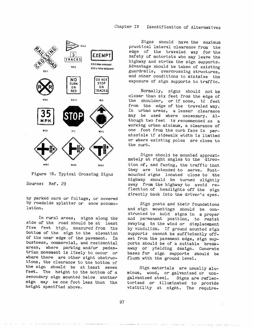
-., –......, .-Chapter IV laenLll lcaclOn or ~lternatt~e~
81s1
W,o., n,,.,,
W,3., ,,.,
nEXEMPT
uDO NOTSTOPON
TRACKS
R&a
o
4
e
W31,
@@@
.,0.2 w,0.3 WI04
Figure 18. Typical Crossing
Source: Ref. 29
by parked cars or foli.age,orby roadside splatter or snowlation.
Signs
coveredaccmu-
In rural areas, signs along theside Of the rOad should be at leastfive feet high, measured from thebottom of the sign tO the ele~atiOnof the near edge of the pavement. Inbusiness, comercial, and residentialareas, where parking and/or pedes-trian movement is likely to occur orwhere there are other sight obstruc-tions, the clearance to the bottom ofthe sign should be at least sevenfeet. The height to the bottom of asecondary sign mounted belOw anotherSign may be one foot less than theheight specified above.
signs should have the maximumpractical lateral clearance from theedge of the traveled way for theSafety of motorists who may leav~ the
highway and strike the sign supports.Advantage should be taken of existingguardrails, overcrossing structmes,and other conditions to minimize theexposure of sign supports to trsffic.
Normally, signs should not becloser than six feet from the edge ofthe shoulder, or if ~One, 12 feetfrom the edge of the traveled way.In urban areas, a lesser clearancemay be used where necessary. Al-though two fee: is recowended as aworking urban minimm, a clearance ofone foot from the curb face is per-missible if sidewalk width is limitedor where existing poles are close to
the curb.
Signs should be mounted approxi-mately at right angles to the direc-tion of, and facing, the traffic thatthey are intended to serve. POst-mounted signs located close to thehighway should be turned slightlyaway from the highway to avoid re-flection of headlights off the signdirectly back into the driverfs eyes.
Sign posts and their foundationsand si~~ momtings should be con-structed to hold signs in a properand permnent position, to resistswaying in the wind or displacementby vandalism. If ground momt ed signsupports cannot be sufficiently Off-set from the pavement edge, sign sup-ports should be of a suitable break-away or yielding design. Concretebases for sign supports should beflush with the ground level.
Sign materials are usually alu-minu, wood, or galvanized or nOrl-galvanized steel. Signs are reflec-torized or illwinated to providevisibility at night. The require-
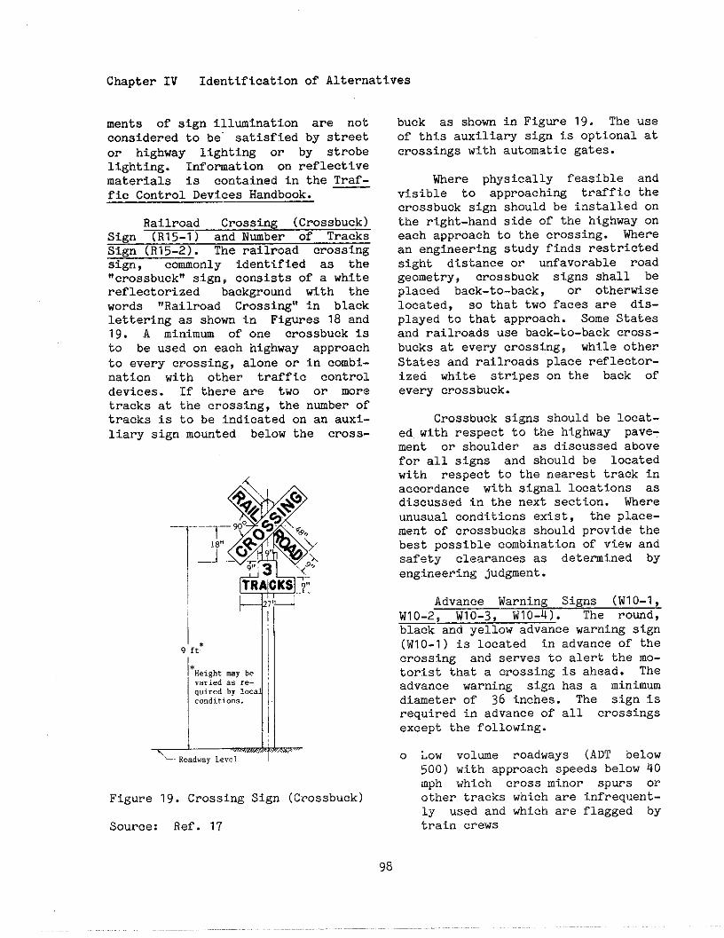
Chapter IV Identification of Alternatives
ments of sign illumination are notconsidered to be” satisfied by streetor highway lighting or by strobelighting. Information on reflectivematerials is contained in the Traf-fic Control Devices Handbook.
Railroad Crossing (Crossbuck)Sign (Rl5-1) and Number of TracksSign (R15-2). The railroad crossingsign, commonly identified as the!!crossb~ek,,sign, consists Of a white
reflectorized background with thewords ,,Railroad Crossing” in blacklettering as shown in Figures 18 andlg. A minimum of one crossbuck isto be used on each highway approachto every crossing, alone or in combi-nation with other traffic controldevices. If there are two or more
tracks at the crossing, the nmber oftracks is to be indicated on an auxi-liary sign mounted below the cross-
z--
9’ft* Ill
q.i.edbY10C.CO”ditio”e. 1I
Figure 19. Crossing Sign (Crossbuck)
Source: Ref. 17
buck as shown in Figwe 19. The useof this auxiliary sign is optional atcrossings with automatic gates.
Where physically feasible andvisible to approaching traffic thecrossbuck sign should be installed onthe right-hand side of the highway oneach approach to the crossing. Wherean engineering study finds restrictedsight distance or unfavorable roadgeometry, crossbuck signs shall beplaced back-to-back, or otherwiselocated, so that two faces are dis-played to that approach. Some Statesand railroads use back-to-back cross-bucks at every crossing? while otherStates and railroada place reflector-ized white stripes on the back ofevary crossbuck.
Crossbuck signs should be locat-ed with respect to the highway pave-ment or shoulder as discussed abovefor all signs and should be locatedwith respect to the nearest track inaccordance with signal locations asdiscussed in the next section. Whereunusual conditions exist, the place-ment of crossbucks should provide thebest possible combination of view andsafety clearances as determined byengineering judgment.
Advance Warning Signs (WlO-1,WIO-2, W1O-3, W1O-4). The round,black and yellow advance warning sign(W1O-1) is located in advance of thecrossing and serves to alert the mo-torist that a crossing is ahead. Theadvance warning sign has a minimumdiameter of 36 inches. The sign isrequired in advance of all crossingsexcept the following.
o Low volme roadways (ADT below500) with approach speeds below 40mph which cross minor spurs orother tracks which are infrequent-ly used and which are flagged bytrain crews
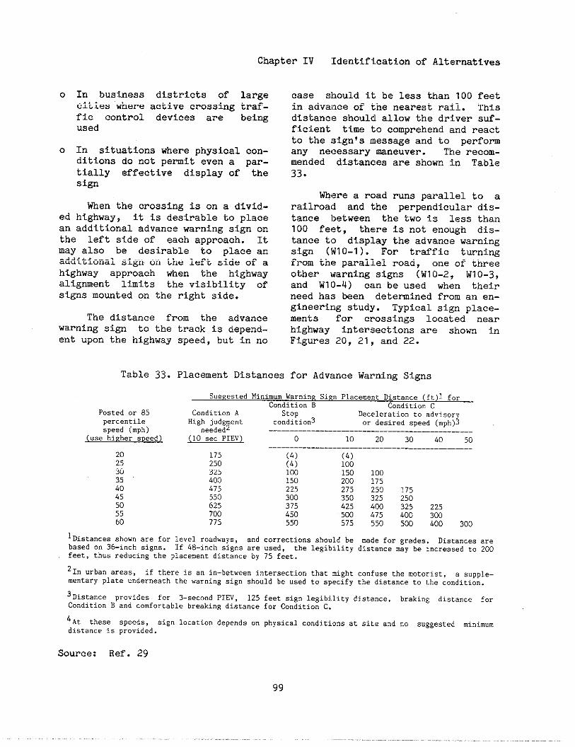
Chapter IV Identification of Alternatives
o In business districts ofcities where active crossingfic control devices areused
large
traf -
bei~
o In situations where physical con-dition do not pemit even a par-tially affective display of thesign
When the crossing is on a divid-ed highway, it is desirable to placean additional advance warning sign onthe left side of each approach. Itmay also be desirable to place anadditional sign.on the left 5ide of ahighway approach when the highwayalignment limits the visibility ofsigns mounted on the right side.
The distance from the advancewarning sign to the track is depend-ent upon the highway speed, but in no
Table 33. Placement Digtances
case should it be less than 100 feetin adva]!ceof the nearest rail. Thisdistance should allow the driver suf-ficient time to comprehend and reactto the sign’s message and to perfomany necessary Mneuver. The recom-mended distances are shown in Table33.
Where a road runs parallel to arailroad and the perpendicular dis-tance between the two is less than100 feet, there is not enough dis-tance to display the advance warningsign (W1O-1). For traffic turningfrom the parallel road, one of th~eeother warning signs (WlO-2, WIO-3,and W10-4) can be used when theirneed has been detemined from an en-gineering study. Typical sign place-ments for crossings located nearhighway intersections are shown inFigures 20, 21, and 22.
for Advance Warning Signs
Su8gested Minimum Warning SifinPlaceme”c Distance (ft)l for
Condition B Condition C
Posted or 85 Co”ditio” A stop Decelerationto advisorype..e.ri1e High judgment co”ditio”3 ox desired speed (mph)3speed (mph) “eededz
~“.e hi~her speed) (10 s,. PIEv) o 10 20 30 40 50
202530354045505560
175250325Loo475550625700?75
(4)(4j1001502253003?5450550
(4)100150 100200 175275 250 175350 325 250425 400 325 225500 4?5 400 300575 550 500 400 300
lDistances show” are for 1.”.] roadw,ys, and correcti.”s should be made for grades, Disca”ces arebased on 36-inch signs. If 48-inch signs are used, the legibility distance mey be Increased to 200feet, thus reducing the placement distance by 75 feet.
21, “rb.nareas, if thereis .“ i“-betweenintersectionthatmightc.”f.se the motorist, . supple-mentaryplate.“derneath the war”i”g slg” should be used to specify the dist.”ce to the co”dicio”.
3Distance p.o.id.. for 3-seco.d PIEV, 125 feet sign legibility distance, h..ki”g dist.”.e f..Condition B a“d comfortable breaking dista”.e for Condition C.
4At these speeds, Sign location depends .“ physical c.”diri... at site .“d .0 .“gge,ted ~lnim”mdistance is provided.
Source: Ref. 29
99
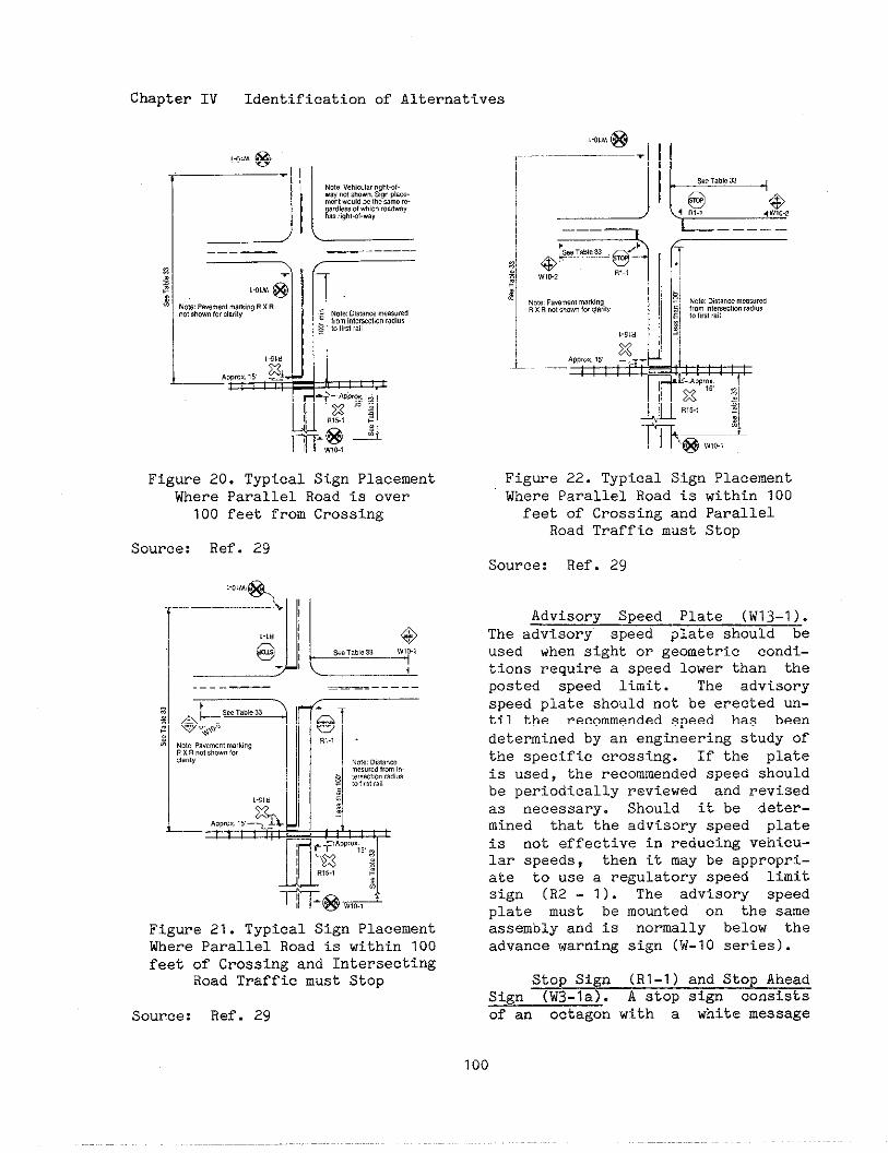
Chapter IV Identification of Alternatives
Figure 20. Typical Sign PlacementWhere Parallel Road is over
100 feet from Crossing
Source: Ref. 29
Figure 21. Typical Sign PlacementWhere Parallel Road is within 100feet of Crossing and Intersecting
Road Traffic must Stop
Source: Ref. 29
,+,. @.
I ‘!1 F=”’L
Figure 22. Typical Sign PlacementWhere Parallel Road is within 100feet of Crossing and Parallel
Road Traffic must Stop
Source: Ref. 29
Advisory Speed Plate (W13-1).The advisory speed plate should beused when sight or geometric condi-tions require a speed lower than theposted speed limit. The advisoryspeed plate should not be erected un-til the recommended speed has beendetermined by an engineering study oftinespecific crossing. If the plateis used, the recommended speed shouldbe periodically reviewed and revisedas necessary. Should it be deter-mined that the advisory speed plateis not effective in reducing vehicu-lar speeds, then it may be appropri-ate to use a regulatory speed limitsign (R2 - 1). The adviso~ speedplate must be mowted on the sameassembly and is normally below theadvance warning sign (W-1O series).
Stop Sign (Rl-1) and Stop AheadSign (W3-la). A stop sign consistswan octagon with a white message
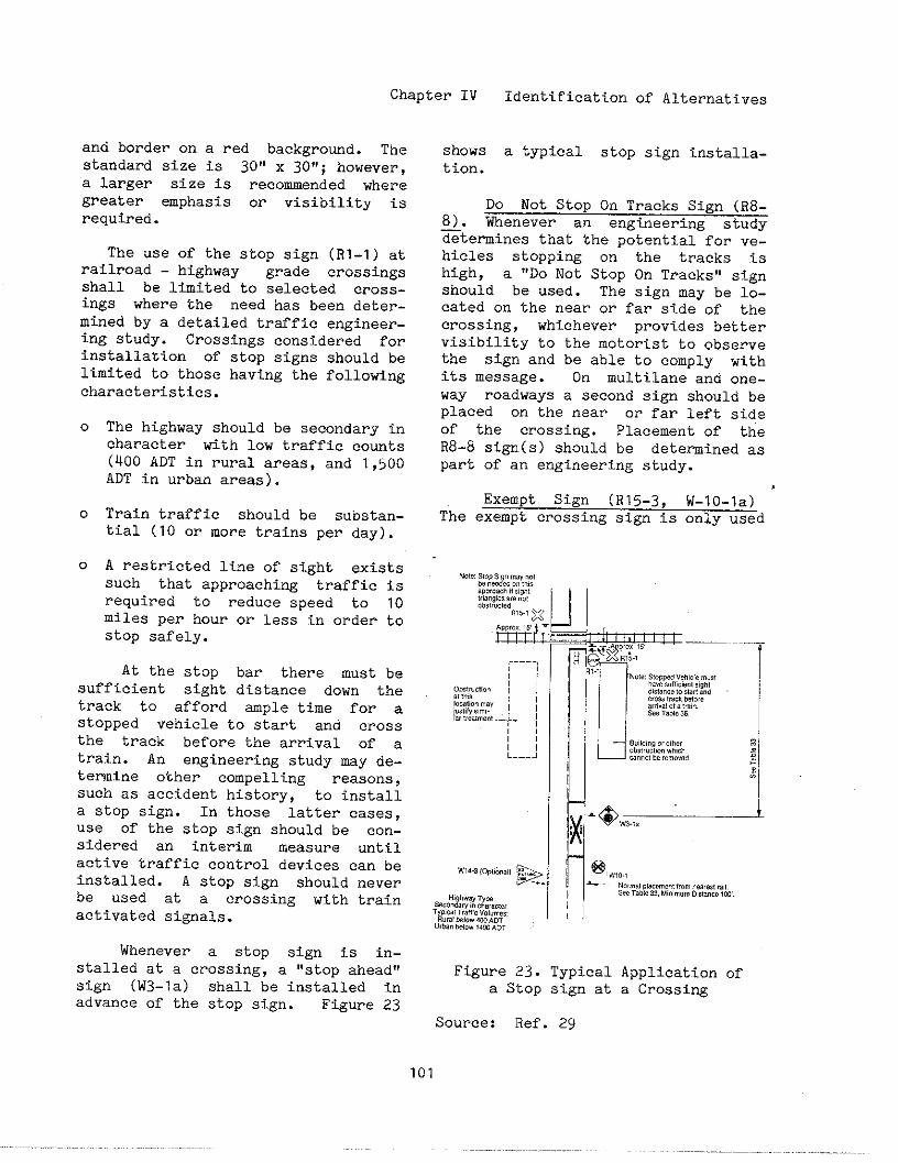
Chapter IV
and border on a red background. Thestandard size is 30” x 3071;however,a larger size is recommended wheregreater emphasis or visibility iSrequired.
The use of the stop sign (R1-1) atrailroad - highway grade crossingsshall be limited to selected cross-ings where the need has been deter-mined by a detailed traffic engineer-ing study. Crossings considered forinstallation of stop signs should belimited to those having the followingcharacteristics.
0
0
0
The highway should be secondary incharacter with low traffic ~ount~(400 ADT in rural areas, and 1,500ADT in urban areas).
Train traffic should be substan-tial (10 or more trains per day).
A restricted line of sight existssuch that approaching ‘traffic isrequired to reduce speed to 10miles par hour or less in order tostop safely.
At the stop bar there must besufficient sight distance down thetrack to afford mple time for astopped vehicle to start and crossthe track before the arrival of atrain. An e~ineering study my de-temine other compelling reasons,such as accident history, to installa stop sign. In those latter cases,use of the stop sign should be con-sidered an interim measure untilactive traffic control devices can beinstalled. A stop sign should neverbe used at a crossing with trainactivated signals.
Whenever a stop sign iS in-
stalled at a crossing, a !Istopahead!!
sign (W3-la) shall be installed inadvance of the stop sign. Figure 23
showstion.
Identification of Alternatives
a typical stop sign installa-
Do Not Stop On Tracks Sign (R8-8). Whenever an engineering study~temines that the potential for ve-hicles stopping on the tracks ishigh, a ,,DoNot Stop On Tracks!!signshould be used. The sign may be lo-cated On the near or far side of thecrossing, whichever provides bettervisibility to the motorist to observethe sign and be able to comply withits message. On multilane and One-way roaclwaysa second sign should beplaced on the near or far left sideof the crossing. Placement of theR8-8 sign.(s)should be determined aspart of an engineering study.
Exempt Sign (R15-3, W-lO-la)The exempt crossing sign is only used
Figure 23. Typicala Stop sign at
Application ofa CrOssi~
Source: Ref. 2g
101
Chapter IV Identification of Alternatives
when authorized by law or regulation.
Its purpose is to inform drivers of
vehicles, normally required to stop
at all crossings, that a stop is not
required at a specific crossing un-less a train, locomotive, or otherrailroad equipment is approaching oroccupying the crossing. When used,the exempt sign (R15-3) is placed un-der the crossbuck (R15-1) sign. Asupplemental exempt sign (WIO-la)may be placed under the advance warn-ing sign (WIO-1).
Turn Prohibition Signs (R3-1aand R3-2a). At signalized highwayintersections within 200 feet of acrossing, where traffic signal con-trol is preempted by the approach ofa train, all turning movements towardthe crossing should be prohibited.Turn prohibition signs, “NO RightTurn” (R3-la) and “NO Left Turn” (R3-2a), consist of a 24” x 30” rectanglewith black letters and border on awhite background. These signs are tobe visible only when the turn prohib-ition is in effect; thus a blank-outor internally illwinated sign, orother type of changeable message signmay be used to accomplish this objec-tive. These signs are activated bythe approach of a train using thesae train detection circuitry asflashing light signals. Therefore,these signs could be consideredactive traffic control devices.
No Passing Zone Sign (W14-3).The “NO Passing Zone” sign may be in-stalled at crossings to supplement nopassing pavement markings. This signconsists of black letters and borderon a yellow background and is in theshape of a pennant ,dithdimensions of36” x 48” x 481’. The sign is to beplaced on the left side of the high-way at the beginning of the no pass-ing zone.
2. Pavement Markings
Pavement markings are used tosupplement the regulatory and warningmessages presented by crossing signsand signals. Pavement mrkings havelimitations in that they may be ob-literated by snow, may not be clearlyvisible when wet, and may not be verydurable when subjected to heavy traf-fic.
Pavement markings in advance ofrailroad-highwaywade crossings con-
sist of an X, the letters RR, a nopassing urking for 2-lane roads, andcertain transverse lines as shown inFigure 24. These pavement markingsshall be placed on each approach laneon all paved approaches to crossingswhere crossing signals or automaticgates are located, and at all othercrossings where the prevailing speedof highway traffic is 40 mph orgreater. These markings are also tobe placed at crossings where engi-neering studies indicate there is asignificant potential cotilict be-tween vehicles and trains. Thesemrkings may be omitted at minorcrossings or in urban areas if an en-gineering study indicates that othercrossing devices provide suitablecontrol.
The most common pavement markingmaterial is paint; however, a widevariety of other materials is availa-ble. Pavement urkings are to be re-flectorized by mixing glass beads inwet paint or thermoplastic. Raisedpavement markers can be used to sup-plement pavement mrkings in advanceof crossings. The “X” lane lines andthe stop line can be delineated byraised reflective markers to provideimproved guidance at night and duringperiods of rain and fog. Disadvan-tages of the raised pavement mrkers

Chpter IV Identification of Alternatives
Ath,eel,,ne rn.Aws,,.ha,,,ti ..-.., . . . .. .. .. . . . . . ., .,,-.,.. .,, ,., .V”W,,,,.centerline foc two-lane approach oPeration onthe aPP,oach to a c,ossi”g.
0“ multi.lane road, the t,a”sverse band,Sh?u!d extend ,.,.s, ,,1 approach /,.,s, ,“d,nd,v, dual RXR symbol, should be “,ed ineach approach lane,
Refer to Standard Alphabet for Highway %g”sa“d Markings for RXR symbol, detail,.
Figue 24. Typical Placement of Warning Sigr!sand Pavement ~rkings
Source: Ref. 17
are the initial cost and the possi-bility of being dmaged or removed bysnow plows.
All pavement markings are to bereflectorized white except for the nopassing markings that are to be re-flectorized yellow. The stop line isto be 2 feet in width and extendacross the approach lanes. The stopline should be located perpendiculartO the highway centerline and approx-imately 15 feet from the nearestrail. Where automatic gates areinstalled, the stop line should belocated approximately eight feet inadvance of where thethe highway surface.
gate–am crosses
C. Active Trtific Control Devices
Active crossing traffic controldevices are those that give warningof the approach or presence of a‘train. They are activated by thepassage of a train over a detectioncircuit in the track except in thosefew situations where manual controlor mnual operakion is used. Activecontrol devices are supplemented withthe sae signs and pavement mrkingsthat are used for passive control.Acttve traffic control devices in-clude flashing light signals, bothpost-mounted and cantilevered, bells,automatic gates~ active advance warn-ing devices, and highway traffic sig-nals. Also included in this sectionis a description of the various meth-ods of t,raindetection.
103
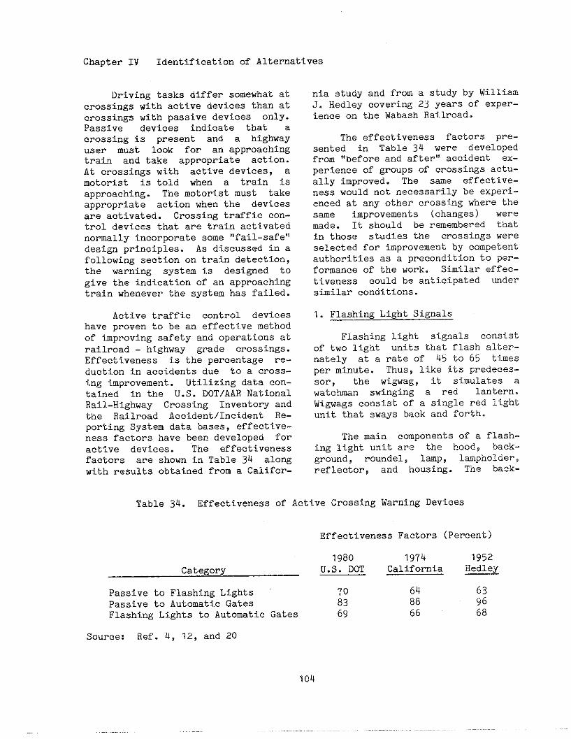
Chapter IV Identification of Alternatives
Driving tasks differ somewhat atcrossings with active devices than atcrossings with passive devices only.Passiva devices indicate that acrossing is present and a highwayuser must look for an approachingtrain and take appropriate action.At crossings with active devices, amotorist is told when a train is
approaching. The motorist must take
appropriate action when the devices
are activated. Crossing traffic cOn-trol devices that are train activatednormally incorporate some “fail-safe”design principles. As discussed in afollowing section on train detection,the warning system is designed togive the indication of an approachingtrain whanever the system has failed.
Active traffic control deviceshave proven to be an effective methodof improving safety and operations atrailroad - highway grade crossings.Effectiveness is the percentage re-duction in accidents due to a cross-
ing improvement. Utilizing data con-
tainad in the U.S. DOT/AAR National
Rail-Highway Crossing Inventory and
tha Railroad Accident/Incident Re-
porting System data bases, effective-
ness factors have been developed for
active devices. The effectivenessfactors are shown i.n Table 34 along
with results obtained from a Califor-
nia study and from a study by WilliamJ. Hedley covering 23 years of exper-ience on the Wabash Railroad.
The effectiveness factors pre-sented in Table 34 were developedfrom “before and after” accident ex-perience of groups of crossings actu-ally improved. The same effective-ness would not necessarily be experi-enced at any other crossing where thesae improvements (changes) wererode. It should be remembered thatin those studies the crossings wereselected for improvement by competentauthorities as a precondition to per-formance of the work. Similar effec-tiveness could be antj.cipated undersimilar conditions.
1. Flashing Light Signals
Flashing light signals COnSistof two light units that flash alter-nately at a rate of 45 to 65 timesper minute. Thus, like its predeces-sor, the wi.gwag, it simulates awatc~n swinging a red lantern.Wi~ags consist of a single rad lightunit that sways back and forth.
The main components of a flash-ing light unit are the hood, back-ground, roundel, lamp, lampholdev,reflector, and housing. The back-
Table 34. Effectiveness of Active Crossing Warning Devices
Effectiveness Factors (Percent)
lg80 1974 1952Category U.S. DOT California Hedley
Passive to Flashing Lights 70 64 63Passive to Automatic Gates 83 88 g6Flashing Lights to Automatic Gates 69 66 68
Source: Ref. 4, 12, and 20
104
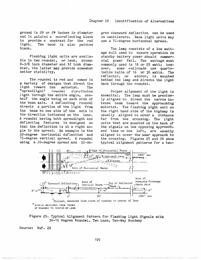
Chapter IV Identification of Alternatives
ground is 20 or 24 inches in diameterand is painted a nonreflecting blackto provide a contrast for the redlight. The hood is also paintedblack.
Flashing light units are availa-ble in two roundel, or lens, sizes:8-3/8 inch diameter and 12 inch diam-eter, the latter my provide somewhatbetter visibility.
The roundel is red and comes ina variety of designs that direct tbelight toward the motorist. The“spreadllghti! roundel distributeslight through the entire angle, one-half the angle being on each side ofthe bem axis. A deflecting roundeldirects a portion of the light fromthe beam to one side of the axis inthe direction indicated on the lens.A roudel having both spreadlight anddeflecting features is designed sothat the deflection is at a right an-gle to the spread. An example is the30-degree horizontal deflection and15-degree vertical spread. A roundelusing a 20-degree spread and 32-de-
gree dok,nwarddeflection can be usedon cantilevers. Back light units may
use a 70-degree horizontal spread.
The lap consists of a low watt-age bulb used to ensure operation onstandby battery power should comer-cial power fail. The wattage mostcomonly used is 18 or 25 watt; how-ever, some railroads use quartz-iodi.debulbs of 16 or 36 watts. Thereflector, or mirror, is mountedbehind the lamp and directs the lightback th~ough the roundel.
Proper alignment of the light isessential. The lamp must be precise-ly aligned to direct the narrow in-tense bea toward the approachingmotorist. The flashing light unit onthe right hand side of the highway isusually aligned to cover a distancefar from the crossing. The ltghtunits that are mounted on the back ofthe signals on the opposing approach,and thus on the left, are usuallyaligned to cover the near approach tothe crossing. Figures 25 and 26 showtypical alignment patterns for a twO-
#cMi”im”m, measured from crown of roadway to ce”cer of lens
“ M, N)M”., MEASURED FROM CROWN
OF ROADWAY TO CENTER OF LENS.
Figure Z5. Typical Alignment Pattern for Flashing Light Signals with30-15 Degree Ro~del, Two Lane, Two-Way Roadway
Source: Ref. 29
105
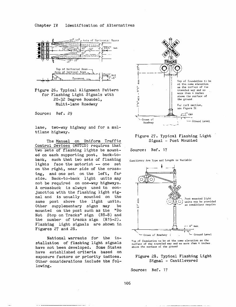
Chapter IV Identificationof Alternatives
Figme 26. Typical Alignment Patternfor Flashing Light Signals with
20-32 Degree Roundel,Multi-lane Roadway
Source: Ref. 29
lane, two-way highway and for a mul-tilane highway.
The Manual on Unifom TrafficControl Devices (MUTCD) requires Vnattwo sets of flashing lights be mount-ed on each supporting post, baek-to-back, such that two sets of flashinglights face the motorist -- one seton the right, near side of the cross-ing, and one set on the left, farside. Back-to-back light units maynot be required on one-way highways.A crossbuck is always used in con-junction with the flashing light sig-nal and is usually mounted on thesame post above the light units.Other supplementary signs my bemounted on the post such as the ,,Do
Not Stop on Tracks” sign (R8-8) andthe number of tracks sign (R15-2).Flashing light signals are shown inFigures 27 and 28.
National warrants for the in-stallation of flashing light signalshave not been developed. Some Stateshave established criteria based onexposure factors or priority indices.Other considerations include the fol-lowing.
~----- -—
-0-mL--*
f<,, curb section,see Figure 31
~ 4,, . . .-...
~crom ofRoadway ‘—Gro””dLevel.-.----
Figure 27. Typical Flashing LightSignal - Post Mounted
Source: Ref. 17
cantilever Arm Type a“d Length <* variable
L— 4 _J
- C.”.. (,[ Roadway , ,L ~rou”d Leve ,
Topof fo.”datio”tobe at thesameele..cio”as thesurfaceof thetraveledway and“o morethan4 inchesabovethe,urfaceof the~ro””d
Figure 28. Typical Flashing LightSi@al - Cantilevered
Source: Ref. 17
106

Chapter IV Identification of Alternatives
o Volume of vehicular traffico Volume of railroad traffico Speed of vehicular traffico Speed of railroad traffico Volume of pedestrian traffico Accident recordo Sight distance restrictions
Flashi~ light signals are gen-erally post-mounted, but where im-proved visibility tO approachingtraffic is required, cantileveredflashing light signals are used.Cantilevered flashing lights may beappropriate when any of the followingconditions exists.
o Multilane highways (two or morelanes in one direction)
o Highways with paved shoulders or aparking lane that would require apost-mounted light to be more than10 feet from the edge of thetravel lane
o Roadside foliage obstructing theview of post - mounted flashinglight si~als
o Line of roadside obstacles such asutility poles (when minor lateraladjustment of the poles would notsolve the problem)
o Distracting backgrounds such asexcessive number of neon signs.(Conversely,cantilevered flashi~lights should not distract fromnearby highway traffic signals.)
o Horizontal or vertical cur~,es at10CatiOnS where extension offlashing lights over tha trafficlane will provide sufficient visi-bility for the required stoppi~sight distance.
A typical installation consistsof one pair of cantilevered lightson each highway approach supplemented
with a ]?airof lights mouted on thesupporti~ mast. However, two ormore pairs of cantilevered flashinglights may be desirable for multi-lane ap]?roaches,as determined by anengineel?ing study. The cantileveredlights can be placed over each laneso that the lights are mutually visi-ble from adjacent driving lanes.
Ca]~tilevers are available withfixed, ~“otatableor walkout sup~rts.The primary disadvantage of the fixedsupport is that maintenance of thelight ulit is usually performed fromequipment in the traffic lane, there-by blOcking highway traffic. Rotata-ble cantilevers can be turned to theside of the highway for maintenancebut noi> for aligning the flashinglights.
Walkout cantilevers allow foreasier maintenance. Standard canti-levers for mounti~ flashing lightsare made with am lengths up to 40feet. Where cantilever am le~th inexcess of 35 feet is required, abridge structure is preferred.
Post-mounted flashing light sig-nals are normally located on theright side of the highway on al1highway approaches to the crossing.Horizontal clearances for flashinglight si~als are discussed in thenext section along with clearancesfor automatic gates.
Additional pairs of light mitsmaY alsO be installed for side roadsintersecti~ the approach highwaynear the crossing or for horizontalcurves. Figure 29 shows the use ofmultiple pairs of lights to cover ahorizontal curve to the left on theapproach highway. A horizontal cmveto the right may be covered by plac-ing another roadside flashing lightunit on the opposite side of thehighway as shown in Figure 30.
107
,..
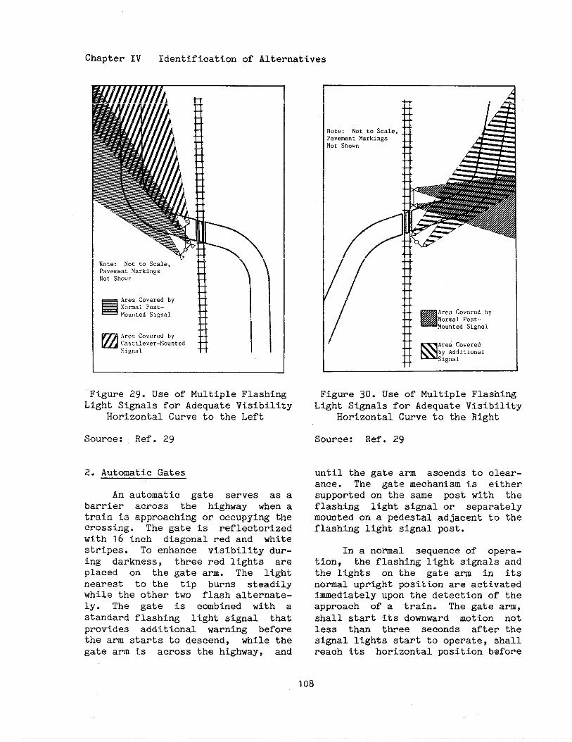
Chapter IV Identificationof Alternatives
u
Figure 29. Usa of Multiple FlashingLight Signals for Adequate Visibility
Horizontal Curve to the Left
Source: Ref. 29
2. Automatic Gates
An automatic gate serves as abarrier across the highway when atrain is approaching or occupying thecrossing. The gate is reflectorizedwith 16 inch diagonal red and whitestripes. To enhance visibility dur-ing darkness, three red lights areplaced on the gate arm. The lightnearest to the tip burns steadilywhile the other two flash alternate-ly. The gate is combined with astandard flashing light signal thatprovides additional warning beforethe arm starts to descend, while thegate arm is across the highway, and
1A
/
Figure 30. Use of Multiple FlashiwLight Signals for Adequate Visibility
Horizontal Curve to the Right
Source: Ref. 29
until the gate arm ascends to clear-ance. The gate mechanism i.s eithersupported on the sme post with theflashing light signal or separatelymo~ted on a pedestal adjacent to theflashing light signal post.
In a nomal sequence of opera-tfon, the flashing light si~als andthe lights on the gate am in itsnormal upright position are activatedimmediately upon the detection of theapproach of a train. The gate arm,shall start its downward motion notless than ttiee seconds after thesignal lights start to operate, shallreach its horizontal position bafore
108
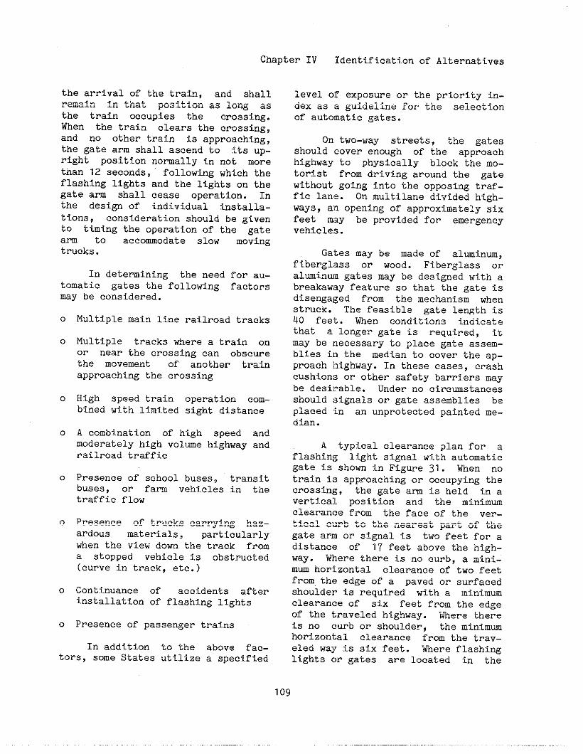
Chapter IV Identification of Alternatives
the arrival of the train, and shallremain in that position as long asthe train occupies the crossing.When the train clears the crossing,and no other train is approaching,the gate arm shall ascend to its up-right position normally in not morethan 12 seconds, following which theflashing lights and the lights on thegate arm shall cease operation. Inthe design of individual installa-tions, consideration should be givento timing the operation of the gatearm to accommodate slow movingtrucks.
In determining the need ~or au-tomatic gates the following factorsmay be considered.
0
0
0
0
0
0
0
0
Multiple main 1~.nerailroad tracks
Multiple tracks where a train onor near the crossing can obscurethe movement of another trainapproaching the crossing
High speed train operation com-bined with limited sight distance
A comb~.nation of high speed andmoderately high volwe highway andrailroad trtific
Presence of school buses, transitbuses, or farm vehicles in thetraffic flow
Presence of trucks carrying haz-ardous materials, particularlywhen the view dom the track froma Stopped vehicle is obstructed(curve in track, etc.)
COnt~.nuance of accidents afterinstallation of flashing lights
Presence of passenger trains
In addition to the above fac-tors, some States utilize a speci.fied
level of exposure or the priority in-dex as a guideline for the selectionof automatic gates.
On two-way streets, the gatesshould cover enough of the approachhighway to physically block the mo-torist from driving around the gatewithout going into the opposing traf-fic lane. On multilane divided high-ways, an opening of approximately sixfeet may be provided for emergencyvehicles.
Gates may be made of almj.num,fiberglass or wood. Fiberglass oral~inUIO gates may be designed with ~breakaway feature so that the gate isdisengaged from the mechanism whenstruck. The feasible gate length is40 feet. When conditions indicatethat a longer gate is required, itmay be necessary to place gate assem-blies in the median to cover the ap-proach l~ighway.In these cases, crashcushions or other safety barriers maybe desi]?able. Under no circumstancesshould signals or gate assemblies beplaced in an unprotected painted me-dian.
A typical clearance plan for aflashing light signal with automaticgate i.sshown in Figure 31. When notrain is approaching or occupying thecrossing, the gate am is held in avertica:l position and the minimmclearanCe from the face of the ver-tical curb to the nearest part of thegate arm or signal is two feet fOr adistance of 17 feet above the high-way. Where thare is no curb, a mini-mm horizontal clearance of two feetfrom.the edge of a paved or surfacedshoulder is required with a minimumclearance of six feet from the edgeof the traveled highway. Where thereis no curb or shoulde~, the minimuhorizontal clearance from the trav-eled wa~?is six feet. Where flashi~lights or gates are located in the
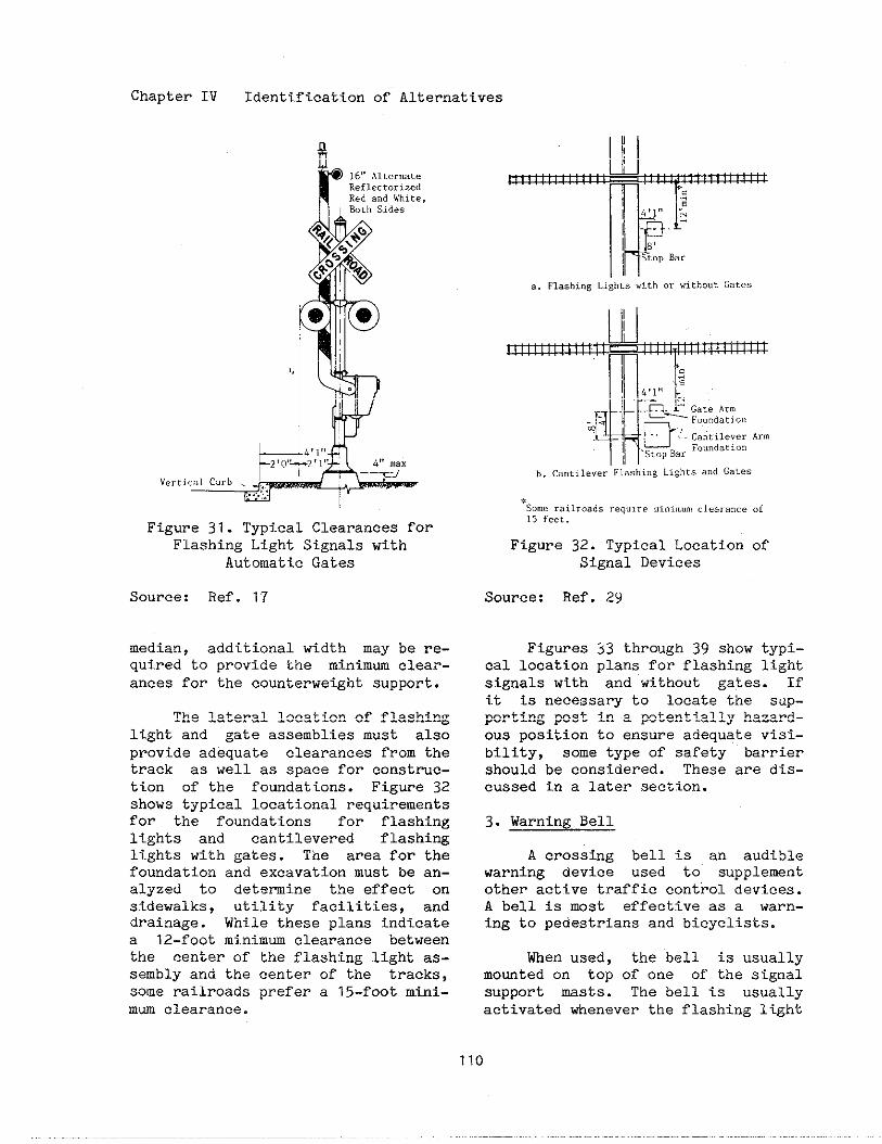
Chapter IV Identification of Alternatives
8r]6,,~lt,,..t.ReflectorizedReda“dWhite,BothSides
,,
& ~fl,,
*! O! T!l!! 4f~...— .-JV.r,i.alcurb. .,.,.,.:,
Figure 31. Typ~.calClearances forFlashing Light Signals with
Automatic Gates
Source: Ref. 17
median, additional width may be re-quired to provide the minimm clear-ances for the counterweight support.
The lateral location of flashinglight and gate assemblies must alsoprovide adequate clearances from thetrack as well as space for construc-tion of the fomdat ions. Figure 32shows typical locational requirementsfor the foundations for flashinglights and cantilevered flashi~lights with gates. The area for thefoundation and excavation must be an-alyzed to detemine the effect onsidewalks, utility facilities, anddrainage. While these plans indicatea 1Z-foot mi.nimm clearance betweenthe center of the flashing light as-sembly and the center of the tracks,some railroads prefer a 15-foot mini-mm clearance.
b. C8”ti1ever”F1ashi”gLightsa“dGales
*Somerailroadsrequireminimumclearanceof15 feet.
Figure 32. Typical Location ofSignal Devices
Source: Ref. 2Y
Figures 33 through 39 show typi-cal location plans for flashing lightsignals with and without gates. Ifi.t is necessary to locate the sup-porting post in a potentially hazard-ous position to ensure adequate visi-bility, some type of safety barriershould be considered. These are dis-cussed in a later section.
3. Warning Bell
A crossing bell is an audiblewarning device used to supplementother active traffic control devices.A bell is most effective as a warn-ing to pedestrians and bicyclists.
When used, the bell is usuallymowted on top of one of the signalsupport masts. The bell is usuallyactivated whenever the flashing 1ight
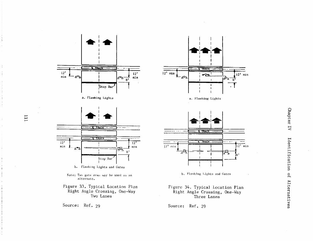
.
.
.. Flashi”~Li8hts
b. FlashingLight.andGate.
Figure 33. Typical Location PlanRight Angle Crossing, One-Way
Two Lanes
Source: Ref. 29
a. F1ashi”g Lights
1 I
7+- < T“&cK ~ —
“’”’’”L-.4:’”’”m’
b. Flashing Lights a“d Gates
Figure 34. Typical Location PlanRight Angle Crossing, One-Way
Three Lanes
Source: Ref. 29
H<
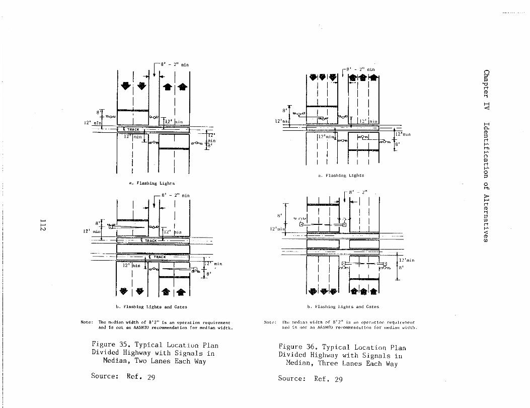
ChapterIV
IdentificationofAlternatives
-c.5,.
-5
112
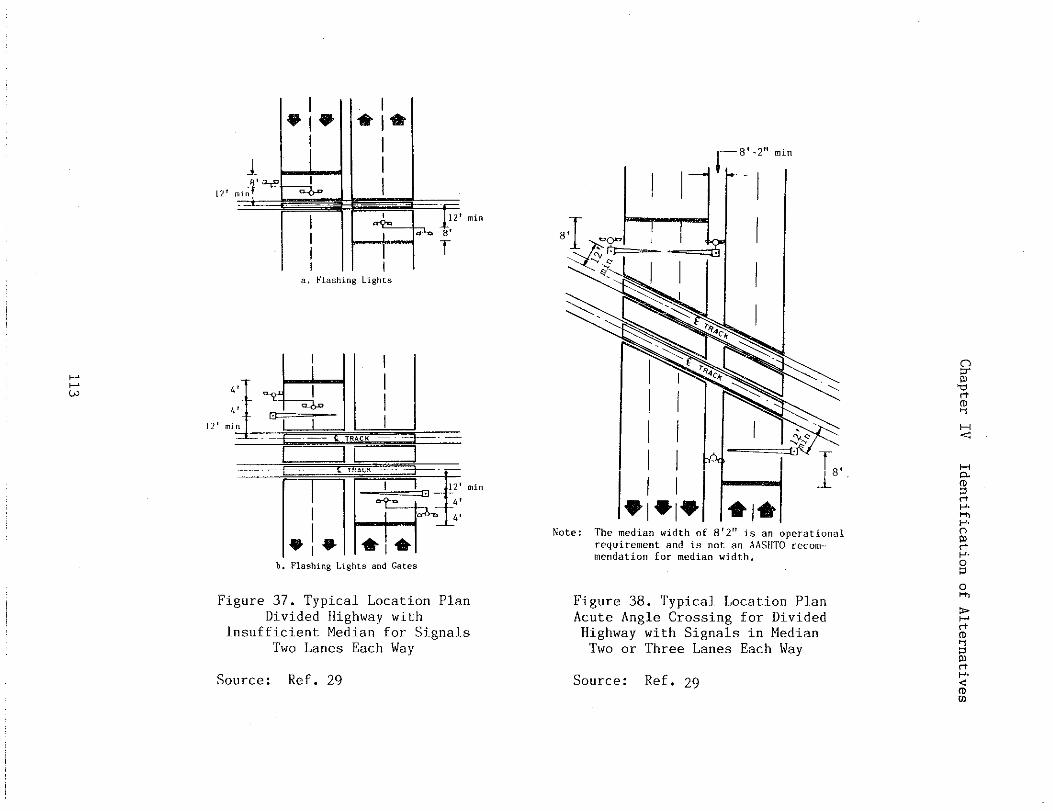
ChapterIV
IdentificationofAlternatives
-mI
_——
—
.--.,

Chapter IV Identificationof
r 8’-2”mi”
Alternatives
Note:Themedia”widthof8’2”isanoperationalrequirementandisnotanAASdTOreco))I–me”datio”formedia”width.
Figure 39. Tvuical Location PlanOb;use Angle-~rossingHighway with SignalsTwo or Three Lanes
Source: Ref. 29
SignalS are operati~.
for Dividedin MedianEach Way
yei.Lowhazard identification beaconsmounted above the advance warni~sign as shown in Figures 40 and 41.The AAWS provides a motorist with ad-vance nrning that a train is ap-proaching the crossi~. The beaconsare connected to the railroad trackcircuit~preach ofcontinuecrossingvated.
and activated on the ap-a train. The AAWS shouldto be activated ~til thesignals have been deacti-
&W1O-1
RR
TOE
qmfiol,i”~,i~n~y,i ControlSy,t?,,(op.,) (Closed)f
Figure 40. Examples of ActiveAdvance Warning Signs
Source: Ref. 29Bell circuit-
ry may be designed so that the bellstops ringing when the lead end ofthe train reaches the crossing. Whengates are used, the bell may be si-lenced when the gate arms descend towithin 10 degrees of the horizontalposition. Silencing the bell whenthe train reaches the crossing orwhen the gates are dom may be de-sired to accommodate residents ofsuburban areas.
4. Active Advance Warning Sign
An active advance warning sign(AAWS) consists of one or two 8-inch
Yellow8eaco”I
IIFigure 41. Example of Cantilevered
Active Advance Warning Sign
Source: Ref. 29
114
Chapter IV Identification of Alternatives
A train-activated advance warn-ing sign should be considered atlocations where the erossi~ flashinglight signals cannot be seen until anapproaching motorist has passed thedecision point (the distance from thetrack from which a safe stop can bemade). Use of active advance warni~signs may require some mOdiftcatiOnof the track circuitry. Considera-tion should be given to providing abackup source of power In the eventof comercial power failure.
The AAWS is sometl.mes supple-mented with a message, either activeor paSSiVe, that indicates the mean-ing of tbe device, e.g. “Train WhenFlashing”. A passive supplementalmessage remains constant while anactive supplemental message changeswhen the device is activated by theapproach of a train.
The AAWS should be placed at thelocation where the advance warningsign would normally be placed. Toenhance vis~.bility at crosstigs withunusual geometry or site cOnditiOns,the devices may be cantilevered orinstalled on both sides of the high-way. An engineeri~ study shoulddetermine the most appropriate loca-tion.
5. Traffic Signals
Highway traffic control signalslocated at intersections within 200feet of a crossing should be pre-empted by the approach of a train.Signals at intersections further than200 feet from a crossing should alsobe preempted if traffic flow is suchthat vehicles queue up on the cross-ing, or if an engineeri~ studydetemines the need for preemption.Railroad-highway grade crossing sig-nals are coordinated with adjacenthighway traffic control signals sothat the operation of these separate
control. devices till at all timescomplement rather than negate each,other. The Manual on Unifom TrafficControl.Devices (MUTCD) stresses that.,,..design, installation,and opera-tion sh~uld be based upon a ~otalsystem approach in order that allrelevant features may be consid-ered.”~6 A primry criterion is toavoid the entrapment of vehicles onthe crossing by conflicting aspectsof the highway signal and the cross-in$ Si~al . The best way to do thisis to prevent vehicle queues onto thetracks by the proper design and oper-atiOn of the dual signal systems.
The preemption feature requiresan electrical circuit between thecontrol relay of the crossing warningsystem and the traffic si~al con-troller. The circuit shall be on theclosed circuit principle, that is,the traffic sf.gnalcontroller is nor-mally energized and the circuit iswired through a closed contact Of theenergized control relay of the cross-ing warning system. This is to estab-lish and maintain the preempted con-ition aluring the time the crossingsignals are in operation. Where mul-tiple or Successive preemption mayoccur from differing modes, trainactuation should receive first prior-ity and emergency vehicles secondpriority.
Crossings without active trafficcontrol devices but near signalizedhighway intersections also present asituation where vehicles may beentrapped on the crossing when atrain is approaching. Thus, preemp-tion of the highway traffic signalshould be considered. If the neces-
16Manual on Unifom Traffic Con-trol Devices, Washington, DC: Fed-eral Highway Atiinistration, 1978,Revised 1979, lg80, lg84.
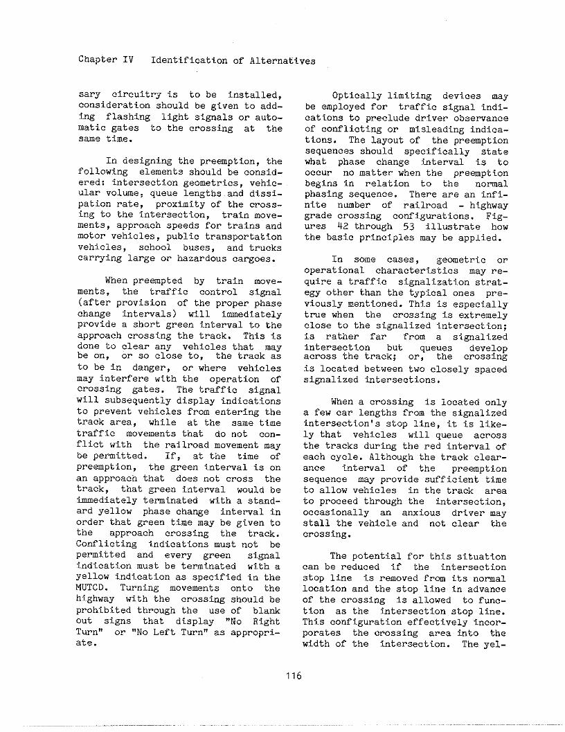
Chapter IV Identificationof Alternatives
Sary circuitry is to be installed,consideration should be given to add-ing flashing light signals or auto-matic gates to the crossing at thesme time.
In designing the preaption, thefollowing elements should be consid-ered: intersection geometries, vehic-ular vOl~e, queue lengths and dissi-pation rate, proximity of the cross-ing to the intersection, train mOve-ments, approach speeds for trains andmOtOr vehicles, public transportationvehicles, school buses, and truckscarrying large or hazardous cargoes.
When preempted by train move-ments, the traffic control si@al(after provision of the proper phasechange intervals) will immediatelyprovide a short green Interval to the
apprOach crossing the track. This iS
done to clear any vehicles that maybe on, or so close to, the track asto be in danger, or where vehiclesmay interfere with the operation ofcrossing gates. The traffic signalwill subsequently display indicationsto prevent vehicles from entering thetrack area, while at the same timetraffic movements that do not con-flict with the railroad movement maybe pemitted. If, at the time ofpreemption, the green interval is onan approach that does not cross thetrack, that green t.nterval would beimmediately teminated with a stand-ard yellow phase change interval inorder that green time may be given tothe approach crossing the track.Conflicting i.ndfcationsmust not bepermitted and every green signalindication must be terminated with ayellow indication as specified in theMUTCD. Turning movements onto thehf.ghway with the crossing should beprohibited through the use of blankout signs that display “NO RightTurn!’ or “NO Left Turn“ as appropri-ate.
Optically limiting devices maybe employed for traffic signal indi-cations to preclude driver observanceof conflicting or misleading indica-tions. The layout of the preemptionsequences should specifically statewhat phase change titerval is tooccur no matter when the preemptionbegins in relation to the normalphasing sequence. There are an infi-nite n~ber of railroad - highwaygrade crossing configwations. Fig-ures 42 through 53 illustrate howthe basic principles may be applied.
In some cases, geometric oroperational characteristics may re-quire a traffic signalization strat-egy other than the typical ones pre-viously mentioned. This is especiallytrue when the crossing is extremelyclose to the signalized intersection;is rather far from a signalizedintersection but queues developacross the track; or, the crossingis located between two closely spacedsignalized intersections.
When a crossing is located onlya few car lengths from the signalizedintersection!s stop line, it is like-ly that vehicles will queue acrossthe tracks during the red interval ofeach cycle. Although the track clear-ance intewal of the preemptionsequence may provide sufficient timeto allow vehicles in the track areato proceed through the intersection,occasionally an anxious driver maystall the vehicle and not clear thecrossing.
The potential for this situationcan be reduced if the intersectionstop line is removed from its nomallocation and the stop line in advanceof the crossing is allowed to func-tion as the intersection stop line.This configuration effectively incor-porates the crossing area tito thewidth of the intersection. The yel-
116
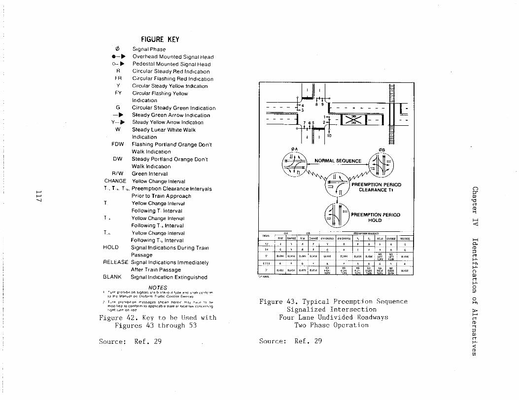
ChapterIV
IdentificationofAlternatives
117
,..

ChapterIV
IdentificationofAlternatives
...—
t
Mlx M
u
118
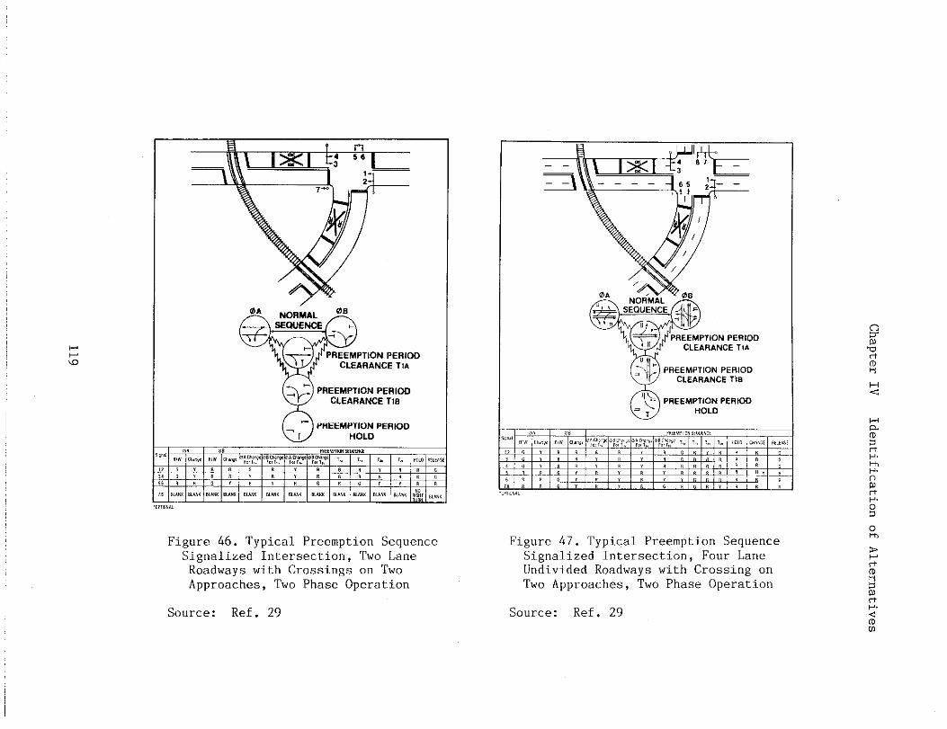
ChapterIV
IdentificationofAlternatives
,Ul
1,1111
Im

ChapterIV
IdentificationofAlternatives
,,
x; 8,,1
----
-—
-*-
—-
--
L
ChapterIV
IdentificationofAlternatives
21
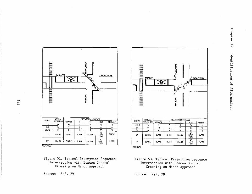
ChapterIV
IdentificationofAlternatives
122
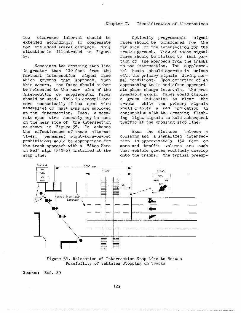
Chapter IV Identification of Alternatives
low clearance interval should beextended accordingly to compensatefor the added travel distance. Thissituation is illustrated in Figwe54.
Sometimes the crossing stop lineis greater than 120 feet from thefarthest intersection signal facewhich governs that approach. Whenthis occurs, the faces should eitherbe relocated to the near side of thetitersection or supplemental facesshould be used. This is accomplishedmore economically if box span wireassemblies or ~st ams are employedat the ~.ntersection. Then, a sepa-rate span wire assembly my be usedon the near side of the titersectionas shown in Figure 55. To enhancethe effectiveness of these alterna-tives, perunent rtght-turn-on-redprohibitions would be appropriate forthe track approach with a “Stop Hereon Red” sign (R1O-6) installed at thestop line.
—
Optically progrmable si~alfaces should be considered for thefar side of the intersection for thetrack approach. View of these signalfaces should be limited to that por-tion of the approach from the tracksto the intersection. The supplemen-tal heads should operate in unisonwith the primry si~als during nor-ml conditions. Upon detection of anapproaching train and after appropri-ate phase change intenals, the pro-grmable si~al faces would displaya green indication to clear thetracks while the prim~ si~alswould display a red indicati.nn inconjunction with the creasing flash-ing light signals to hold subsequenttraffic at the crossing stop ltie.
When the distance between acrossing and a signalized intersec-tion is approximately 150 feet ormore and traffic volwes are suchthat vehicle queues routinely developonto the tracks, the typical premp-
Figure
Source: Ref. 29
R1O-11,
n
r’”
100t ...
)+~, l~g, /FI\
0,..1stop-l,.,w kstion
\ - - -– —*––——
+—— — —
+ F
\
‘\~-------54. Relocation of Intersection Stop Line to ReducePossibility of Vehicles Stoppi~ on Tracks
123
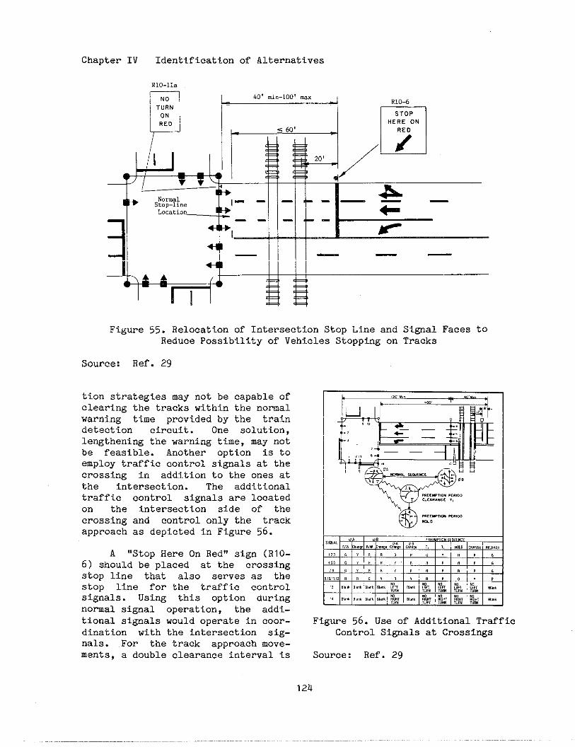
Chapter IV Identification of Alternatives
m R10-6——
I STOPHERE ON
,/ ,I1/
~/
m20,
4
Iw Normal &S,op-line 1- - — ‘-- ———Lo.atio” +
I -- - --11 +, II IIIF
Figure S5. Relocation of Intersection Stop Line and Si@al Faces toReduce Possibility of Vehicles Stopping on Tracks
Source: Ref. 29
tion strategies may not be capable ofclearing the tracks within the nomalwarning time provided by the traindetection circuit. One solution,lengtheni~ the warning time, may notbe feasible. Another option is toemploy traffic control signals at thecrossing in addition to the ones atthe intersection. The additionaltraffic control signals are locatedon the intersection side of thecrossing and control only the trackapPrOach as depicted in Figure 56.
A ,,stopHere on Red!!sign (RlO-
6) should be placed at the crossingstop line that also serves as thestop line for the traffic controlsignals. Using this option duringnomal signal operation, the addi-tional signals would operate in coor-dination with the intersection sig-nals. For the track approach move-ments, a double clearance interval is
Figure 56. Use of Additional TrafficControl Signals at CrOssi~s
Source: Ref. 29
124
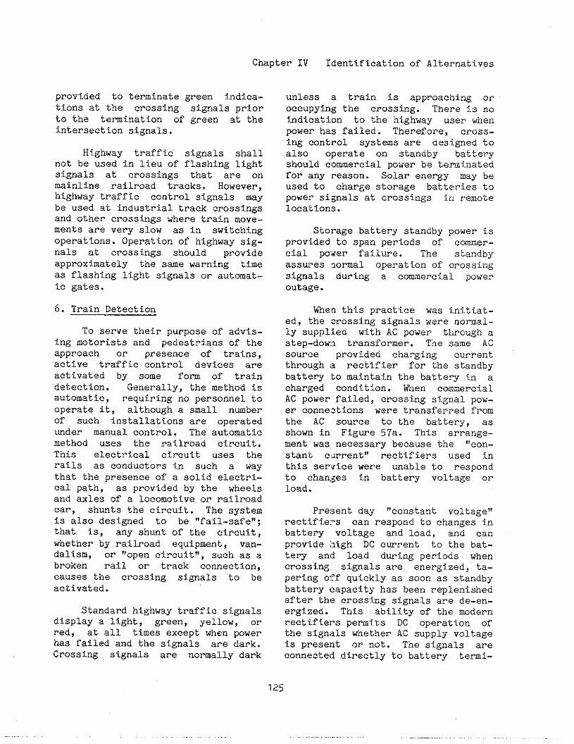
Chapter IV Identification of Alternatives
provided to terminate green t.ndica-tions at the crossing signals priorto the temi.nation of green at theintersection signals.
Highway traffic signals shallnot be used in lieu of flashing lightsignals at crossings that al-e onmainline railroad tracks. However,highway traffic control signals maybe used at industrial track crossingsand other crossings where train move-ments are very slow as in switchingoperations. Operation of highway sig-nals at crossings should provideapproximately the sae warning timeas flashing light signals or automat-ic gates.
6. Train Detection
To Serve their purpose of advis-ing motorists and pedestrians of theapproach or presence of trains,active traffic control devices areactivated by some fom of traindetection. Generally, the method isautomatic, requiring no personnel tooperate it, although a small nmberof such installations are operatedrider mnual control. The automaticmethod uses the railroad circuit.This electrical circuit uses therails as conductors in such a waythat the presence of a solid electri-cal path, as provided by the wheelsand axles of a locomotive or r~llroadcar, shunts the circuit. The systemis also designed to be “fail-safe!!;Vnat is, any shunt of the circuit,whether by railroad equipment, van-dalism, or ,,Open circuit,,, such as a
broken rail or track connection,causes the crossing signals to beactivated.
Standard highway traffic s~.gnalsdisplay a light, green, yellov7, orred, at all times except when powerhas failed and the signals are dark.Crossing signals are normally dark
unless a train is approaching oroccupying the crossing. There is noindication to the highway user whenpower has failed. Therefore, crOss-ing control systems are designed toalso operate on standby batteryshould commercial power be temi.natedfor any reason. Solar energy may beused to charge storage batteries topower signals at crossings j.nremotelocations.
Storage battery standby power isprovided to span periods of comer-cial power failure. The standbyassures normal operation of crossingsignals during a comercial poweroutage.
~en this practice was initiat-ed, the crossing signals were normal-ly supplied with AC power through astep-dowlo transformer. The same ACsource provided charging currentthrough a rectifier for the standbybatte~ to maintain the batte~ in acharged condition. Men commercialAC power failed, crossing signal pow-er connections were transferred fromthe AC source to the battery, asshown in Figure 57a. This arrange-ment was necessary becadse the ,~~~*-
stant current” rectifiers used inthis servtce were unable to respondto changes in battery voltage orload.
Present day “constant voltage!!rectifiers can respond to changes inbattery voltage and load, and canprovide l?tgh DC cwrent to the bat-te~ and load during periods whencrossing signals are energ~.zeal,ta-pering Oj!fquickly as soon as standbybattery capacity has been replenishedafter the crossing signals are de-en-ergized. This ability of the modernrectifiers permits DC operation ofthe signals whether AC supply voltageis present or not. The signals areconnected directly to battery temi-
125
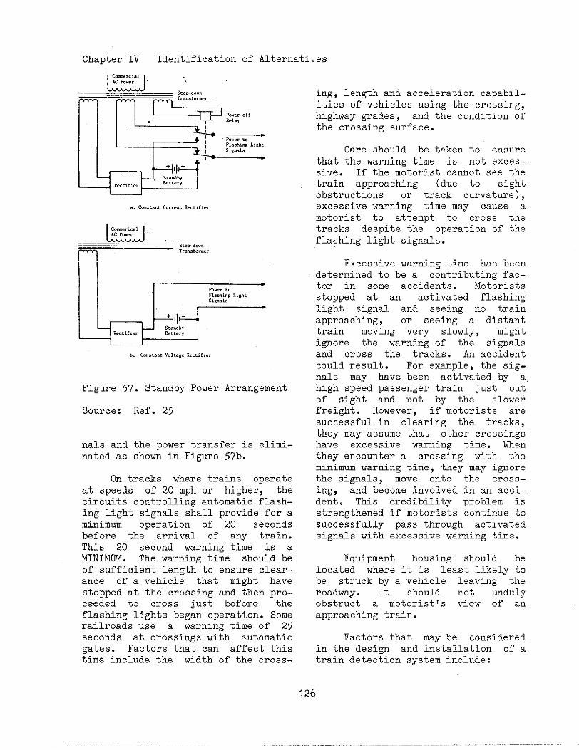
Chapter IV Identification of Alternatives
W9b.m“.,.”,“.,1.,,RCc,i,.,r
Figure 57. Standby Power Arrangement
Source:
nals andnated as
Ref. 25
the power transfer is elimi-shom in Figure 5?b.
On tracks where trains operateat speeds of 20 mph or higher, thecircuits controlling automatic flash-ing light signals shall provide for aminimum operation of 20 secondsbefore the arrival of any train.This 20 second warning time is aMINIm. The warning time should beof sufficient length to ensure clear-ance of a vehicle that might havestopped at the crc)ssingand then pro-ceeded to cross just before theflashing lights began operation. Somerailroads use a warning time of 25seconds at crossings with automaticgates. Factors that can affect thistime include the width of the cross-
ing, length and acceleration capabil-ities of vehicles using the crossing,highway grades, and the condition ofthe crossing surface.
Care should be taken to ensurethat the warning time is not exces-sive. If the motorist cannot see thetrain approaching (due to sightobstructions or track curvature),excessive warning time may cause amotorist to attempt to cross thetracks despite the operation of theflashing light signals.
Excessive warning time has beendetermined to be a contributing fac-tor in some accidents. Motoristsstopped at an activated flashinglight signal and seeing no trainapproaching, or seeing a distanttrain moving very slowly, mightignore the warning of the signalsand cross the tracks. An accidentcould result. For example, the sig-nals may have been activated by ahigh speed passenger train just outof sight and not by the slowerfreight. However, if motorists aresuccessful in clearing the tracks,they may assume that other crossingshave excessive warning time. menthey encomter a crossing with theminimum warning time, they may ignorethe signals, move onto the cross-ing, and become involved in an acci-dent. This credibility problem isstrengthened if motorists continue tosuccessfully pass through activatedsignals with excessive warning time.
Equipment housing should belocated where it is least likely tobe struck by a vehicle leaving theroadway. It should not undulyobstruct a motorist!s view of anapproaching train.
Factors that may be consideredin the design and installation of atrain detection system include:
126
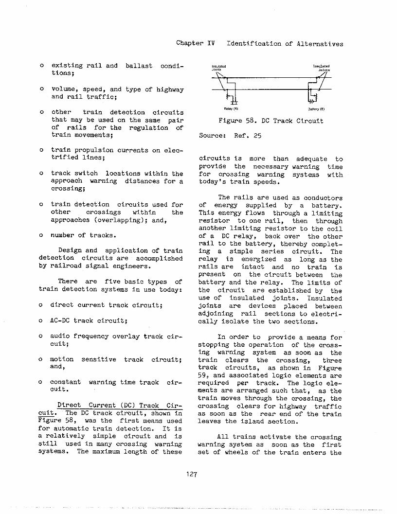
Chapter IV l:dentifieationof Alternatives
0
0
0
0
0
0
0
existing rail and ballast condi-tions;
volwe, speed, and type of highwayand rail traffic;
other train detection circuitsthat may be used on the same pairof rails for the regulation oftrain movements;
train propulsion currents on elec-trified lines;
track switch locations within theaPPrOach warning distances for acrossing;
train detection circuits used forother crossings within the
approaches (overlapping);and,
nmber of tracks.
Design and application of traindetection circuits are accomplishedby railroad signal engineers.
There are five basis types oftrain detection systems in use today:
0
0
0
0
0
direct current track circuit;
AC-DC track circuit;
audio frequency overlay track cir-cuit;
motion sensitive track circuit;and,
constant warning time track ciP-Cuit.
Direct Current (DC) Track Cir-cuit. The DC track circuit, shown inFigure 58, was the first means usedfor automatic train detection. It iSa relatively simple circuit and isstill used in mny crossing warningsystems. The maximum length of these
—R.(8,(,, aa!t,w,,)
Figure 58. DC Track Circuit
Source: Ref. 25
circuits is more thanprovide the necessaryfor crossing warningtoday’s train speeds.
The rails are used
adequate towarning timesystems with
as conductorsof energy supplied by a battery.This energy flows through a limitingresistor to one rail, then throughanother limiting resistor to the coilof a DC relay, back over the otherrail to the battery, thereby complet-ing a simple series circuit. Therelay is energized as long aS therails are intact and no train ispresent on the circuit between thebattery and the relay. The limits ofthe circuit are established by theuse of insulated joints. Insulatedjoints are devices placed betweenadjoining rail sections to electri-cally isolate the two sections.
In order to provide a means forstopping the operation of the cross-ing warning system as soon as thetrain clears the crossing, threetrack circuits, as shown in Figure59, and associated logic elements areTequired per track. The logic ele-ments are arranged such that, as thetrain moves through the crossing, thecrossing clears for highway trafficas soon as the rear end of the trainleaves the island section.
All trains activate the crossingwarning system as soon as the firstset of wheels of the train enters the
127
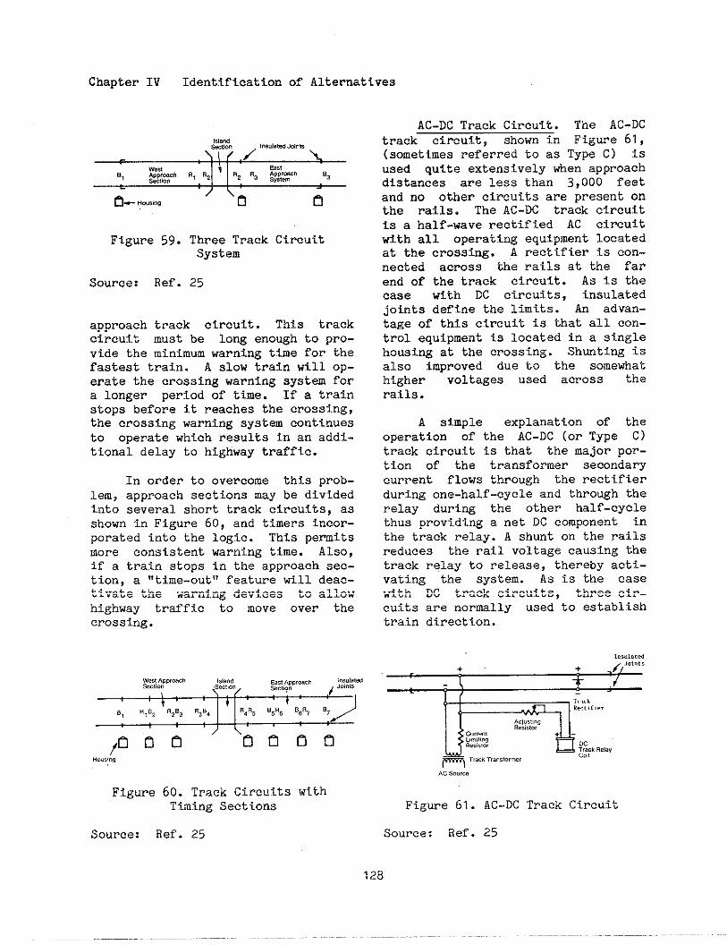
Chapter IV Identification of Alternatives
Figure 59. Three Track CircuitSystem
Source: Ref. 25
approach track circuit. This trackcircuit must be long enough to pro-vide the minimum warning time for thefastest train. A slow train will op-erate the crossing warning aysta fora longer period of time. If a trainstops before it reaches the crossing,the crossing warning system continuesto operate which results in an addi-tional delay to highway traffic.
In order to overcome this prob-lem, approach sections may be dividedinto several short track circuits, asshown in Figure 60, and timers incor-porated into the logic. This pemitsmore consistent warning time. Also,if a train stops in the approach sec-tion, a “time-out” feature till deac-tivate the warning devices to allowhighway traffic to move over thecrossing.
HO”aii,
Figure 60. Track CircuitsTiming Sections
Source: Ref. 25
AC-DC Track Circuit. The AC-DCtrack circuit, shown in Figme 61,(sometimes referred to as Type C) isused quite extenstvely when approachdistances are less than 3,000 feetand no other circuits are present onthe rails. The AC-DC track circuitis a half-wave rectified AC circuitwith all operating equipment locatedat the crosstig. A rectifier is con-nected across the rails at the farend of the track circuit. As is thecase with DC circuits, insulatedjoints define the limits. An advan-tage of this circuit is that all con-trol equipment is located in a singlehousing at the crossing. ShutiW isalso improved due to the somewhathigher voltages used across therails.
A simple explanation of theoperation of the AC-DC (or Type C)track circuit is that the major por-tion of the transformer secondarycurrent flows through the rectifierduring one-half-cycle and through therelay during the other half-cyclethus providing a net DC component inthe track relay. A shunt on the railsreduces the rail voltage causing thetrack relay to release, thereby acti-vating the system. As is the casewith DC track circuits, three cir-cuits are normlly used to establishtrain direction.
Figure 61. AC-DC Track Circuit
Source: Ref. 25
128

Chapter IV Identification of Alternatives
Audio Frequency Overlay TrackCircuit (AFO). The AFO track cir-cuit, shorn in Figure 62, is similarin application to the DC track cir-cuit, except that it can be superim-posed over other circuits which mayexist on the rails. Instead of thebattery and relay used in the DC cir-cuit, a transmitter and receiver ofthe same frequency are used for eachAFO track circuit. No insulatedjoints are required with this type ofcircuit.
The AFO track circuit uses an ACsignal applied to the rails through atransmitter. This signal is trans-mitted via the rails to a ~e~etver atthe opposite end of the track cir-cuit, which converts the AC signal toDC to operate a relay, which in turn,PerfO~s the function of operatingthe warning devices via the control~Qgic similar to the DC track cir-cuit. Once again, three circuits arerequired to establish the directionin which the train is moving.
Figure 62. Audio Frequency OverlayTrack Circuit
Source: Ref. 25
Motion Sensitive Track Circuit.This type of circuit employs audiofrequencies similar to the AFO equip-ment and is desi~ed to detect thepresence, as well as the directiOn ofmotion, of a train by continuouslymOnitOping the track circuit tiped-ance. AS long as the track circuitis unoccupied or no train is movingwithin the approach, the impedance of
the track circuit is relatively con-stant. A decreasing track circuitimpedance indicates that a train ismoving toward the crossing. If atrain should subsequently stop, tileimpedance will again remain at a COO-stant value. If the train is movi]!gaway from a CrOSShg, the impedancetill increase. Thus, if the tra:instops on the approach, or moves awayfrom the crossing, the crossing warlt-ing system Is deactivated and thecrossing is cleared for highway traf-fic.
‘Thistype of circuit is advantfL-geous where trains stop or condu[:tswitching operations within the nor-mal a)?proach limits of a particularcrossing. All powered equipment ~.slocated at the crossing with tileadditional advant~e that insulat{!djoints are not required when appli<!din a hi-directtonal manner, as shOl;nin Figure 63. Adjacent crossing cir,-cuits can be overlaid and overlappc!dwith other train detection circuits.Tuned electrical shunts are requiredto de?fne the end limits of motic,nsensitive circuits and coupling Unit,sare required to bridge any existir~ginsulated joints used in ConjmCtiC,n
with other types of track ~ircuit,ssuch as might be required for waysidesignaling purposes.
,s,.”.*.!,.”
--u n.”,,,,
Figure 63. Motion Sensitive TrackCircuit, Bi-Directional Appltcatiorr
Source: Ref. 25
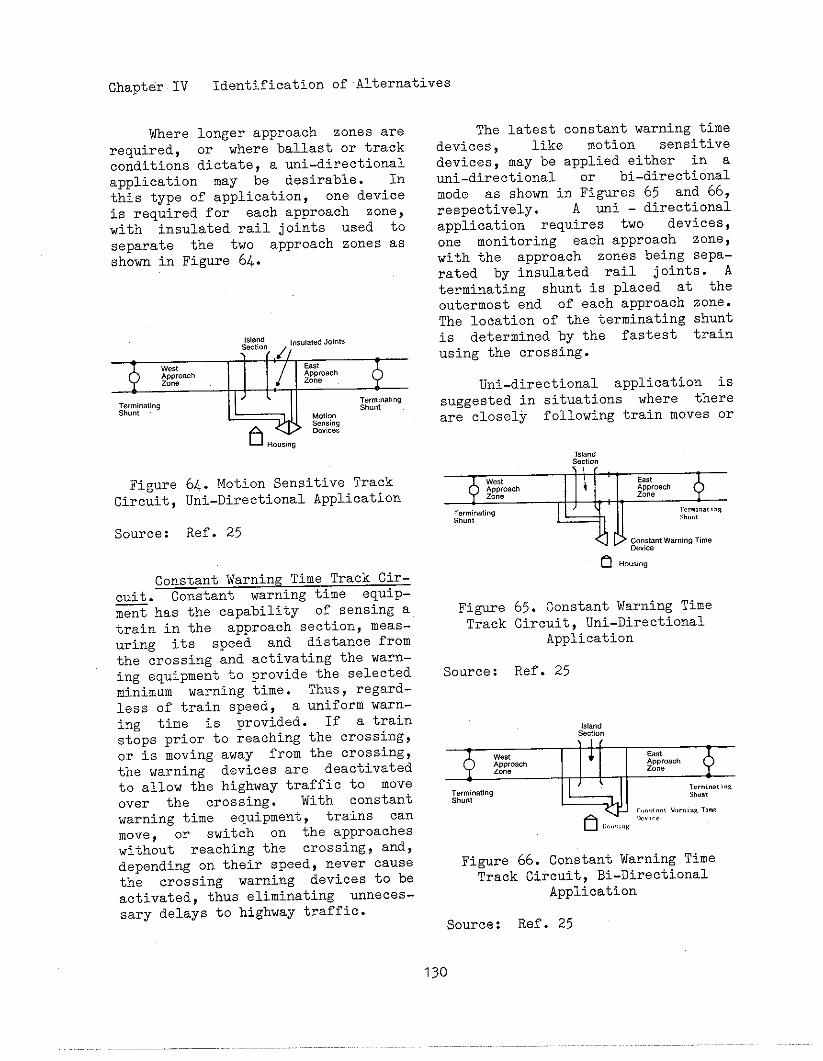
Chapter IV Identification of Alternatives
Where longer approach zones arerequired, or where ballast or trackconditions dictate, a mi-directionalapplication may be desirable. Inthis type of application, one deviceis required for each approach zone,with insulated rail joints used toseparate the two approach zones asshown iriFigure 6k.
The latest constant warning timedevices, like motion sensitivedevices, may be applied either in ami-directional or hi-directionalmode as shown in Figures 65 and 66,respectively. A uni - directionalapplication requires twO devices,one monitoring each approach zone,with the approach zones being sepa-rated by insulated rail jOints. Aterminating shunt is placed at theoutermost end of each approach zone.The location of the terminating shuntis determined by the fastest train
\ (,dl using the crossing.
+
west East;g:y~ ;~~yh
4 Uni-directional application is~“:~q
FigureCircuit,
Source:
W)\ gu:pg
6...,,”,‘;;ii:64., Motion Sensitive TrackUni-Directional Application
Ref. 25
Constant Warning Time Track Cir-cuit. Constant warning time equip-ment has the capability of sensing atrain in the approach section, meas-uring its speed and distance fromthe crossing and activating the warn-ing equipment to provide the selectedminimum warning time. Thus, regard-less of train speed, a unifOrm warn-ing time is prOvided. If a trainstops prior to reaching the crossing,or is moving away from the crossing,the warning devices are deactivatedto allow the highway traffic to moveover the crossing. With constantwarning time equipment, trains canmove, or switch on the approacheswithout reaching the crossing~ and,depending on their speed, never causethe crossing warning devices tO beactivated, thus eliminating ~neces -sary delays to highway traffic.
suggested in situations where thereare closely following train moves or
Figure 65. Constant Warning TimeTrack Circuit, Uni-Directional
Application
Source: Ref. 25
Figure 66. Constant Warning TimeTrack Circuit, Bi-Directional
Application
Source: Ref. 25
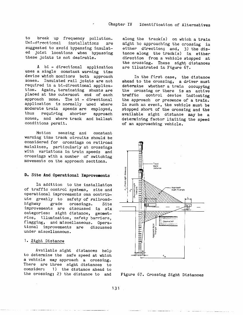
Chapter IV Identification of Alternatives
to break up frequency pollution.Uni-directional installations aresuggested to avoid bypassing insulat-ed joint 10catiOns when bypassingthese joints is not desirable.
A bi - directional applicationuses a single constant warning timedevice which monitors both approachzones. Insulated rail joints are notrequired in a hi-directional applica-tion. Again, terminating shuts areplaced at the outemost end of eachapproach zone. The bi - directionalapplication is nomally used wheremoderate train speeds are employed,thus requiring shorter approachzones, and where track and ballastconditions permit.
Motion sensing and constantwarning time track circuits should beconsidered for crossings on railroadmainlines, particularly at crossingswith variations in train speeds andcrossings with a number of switchingmovements on the approach sections.
D. Site And Operational Improvements
In addition to the installationof traffic control systems, site andoperational improvements can contrib-ute greatly to safety of railroad-highway grade crossings. Siteimprovements are discussed in sixcategories: sight distance, geomet-ric, illwination, safety barriers,flagging, and miscellaneous. Opera-tional improvements are discussedunder miscellaneous.
1. Sight Distance
Available sight distances helpto determine the safe speed at whicha vehicle may approach a crossing.There are three sight distances tOconsider: 1) the distance ahead tothe crossing; 2) the distance tO and
along the track(s) on which a trainmight be approaching the crOssing ineither direction; and, 3) the dis-tance along the track(s) in eitherdirection from a vehicle stopped atthe crosstig. These sight distancesare illustrated in Figme 67.
In the first case, the distanceahead to the crossing, a driver mustdetemine whether a train OCCUpyiDgthe crossing or there is an activetraffic control device indicatingthe approach or presence of a train.In such an event, the vehicle must bestopped short of the crossing and theavailable sight distance may be adetermining factor limiting the speedof an approaching vehicle.
ti
—u ““-” -... “., ,, . . . . . .r/\:O,s,,”.,,..~<.. x.:.;?;.:.:s.,
j:
j“
w. .
“H
Ed—
Figure 67. Crossing Sight Distances
131
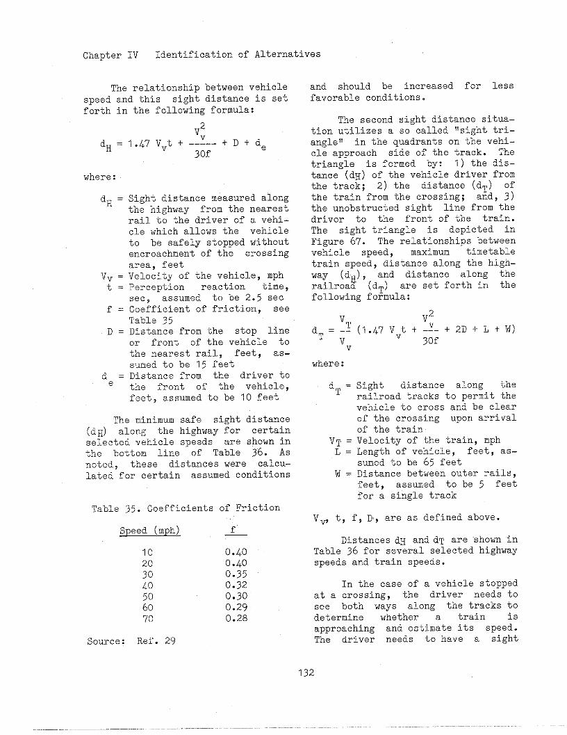
Chapter IV Identification of Alternatives
The relationship between vehiclespeed and this sight distance is setforth in the following formula:
dH =
where:
dH =
Vv =t=
f=
V2?.47 Vvt + --1-- t D t de
3of
Sight distance measured alongthe highway from the nearestrail to the driver of a vehi-cle which allows the vehicleto be safely stopped withoutencroachment of the crossingarea, feetVelocity of the vehicle, mphPerception reaction time,seep assumed to be 2.5 seeCoefficient of friction, seeTable 35
D = Distance from the stop lineor front of the vehicle tothe nearest rail, feet, as-sumed to be 15 feet
de = Distance from the driver tothe front of the vehicle,feet, assumed to be 10 feet
The minimum safe sight distance(dH) along the highway for certainselected vehicle speeds are shown inthe bottom line of Table 3“6. ASnoted, these distances were calcu-lated for certain assumed conditions
Table 35. Coefficients of Friction
Speed (mph) f
10 0.400.40
28 0.3540 0.32
0.302: 0.29
70 0.28
Sw~rce: Ref. 29
and should be increased for lessfavorable conditions.
The second sight distance situa-tion utilizes a so called “sight tri-angle1’ in the quadrants on the vehi-cle approach side of the track. Thetriangle is formed by: 1) the dis-tance (dH) of the vehicle driver fromthe track; 2) the distance (dT) Ofthe train from the crossing; and, 3)the unobstructed sight line from thedriver to the front of the train.The sight triangle is depicted inFigure 67. The relationships betweenvehicle speed, maximum timetabletrain speed, distance along the high-way (d ), and distance along therailroa~ (dT) are set forth in thefollowing formula:
vdT = -~
Vv
where:
dT =
VT =L=
w=
V2(1.47 Vvtt-~-+2D+L+W)
jof
Sight distance along therailroad tracks to permit thevehicle to cross and be clearof the crossing upon arrivalof the trainVelocity of the train, mphLength of vehicle, feet, as-sumed to be 65 feetDistance between outer rails,feet, assumed to be 5 feetfor a single track
v ~, t, f, D, are as defined above.
DistancesdH and dT are ‘shorninTable 36 for several selected highwayspeeds and train speeds.
In the case of a vehicle stoppedat a crossing, the driver needs tosee both ways along the tracks todetermine whether a train isapproaching and estimate its speed.The driver needs to have a sight
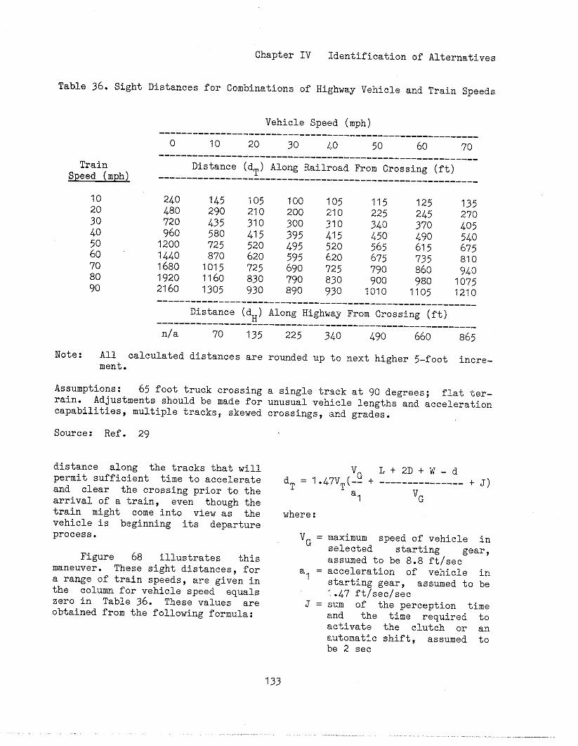
Chapter IV Identification of Alternatives
Table 36. Sight Distances for Combinations of Highway Vehicle and Train Speeds
TrainSpeed (mph)
Vehicle Speed (mph)---------------------------------------------------------
o 10 20 30 1)0 50 60 70---------------------------------------------------------
Distance (dT) Along Railroad From Crossing (ft)---------------------------------------------------------
240 145 105 100 105480
115290
125210
135200 210 225
720 435245
310270
300 31096o
340580
370415 395
405415
1200 ?25450
520:~
495
540
1440520
62o565
870675
595 620 6751680 1015
735?25 690
810725
1920790
1160860
830 790940
8302160
9001305
980930
1075890 930 1010 1105 1210
_________________________________________________________
Distance (dH) Along Highway From Crossing (ft)_________________________________________________________
n/a 70 135 225 340 490 660 865
Note: All calculated distances are rounded up to next higher 5-foot incre-ment.
Assumptions: 65 foot truck crossing a single track at 90 degrees; flat ter-rain. Adjustments should be made for unusual vehicle lengths and accelerationcapabilities,multiple tracks~ skewed crossings, and grades.
Source: Ref. 29
distance along the tracks that willpermit sufficient time to accelerateand clear the crossing prior to thearrival of a train, even though thetrain might come into view as thevehicle is beginning its departureprocess.
Figure 68 illustrates thismaneuver. These sight distances, fora range of train speeds, are given inthe column for vehicle speed equalszero in Table 36. These values areobtained from the following formula:
‘GLt2DtW-d
dT = 1.47VT(-- + --------------- t J)
al ‘G
where:
VG = maximum speed of vehicle inselected starting gear,assumed to be 8.8 ft/sec
al= acceleration of vehicle instarting gear, assumed to be1.47 ft/sec/sec
J = sum of the perception timeand the time required toactivate the clutch or anautomatic shift, assumed tobe 2 sec
133
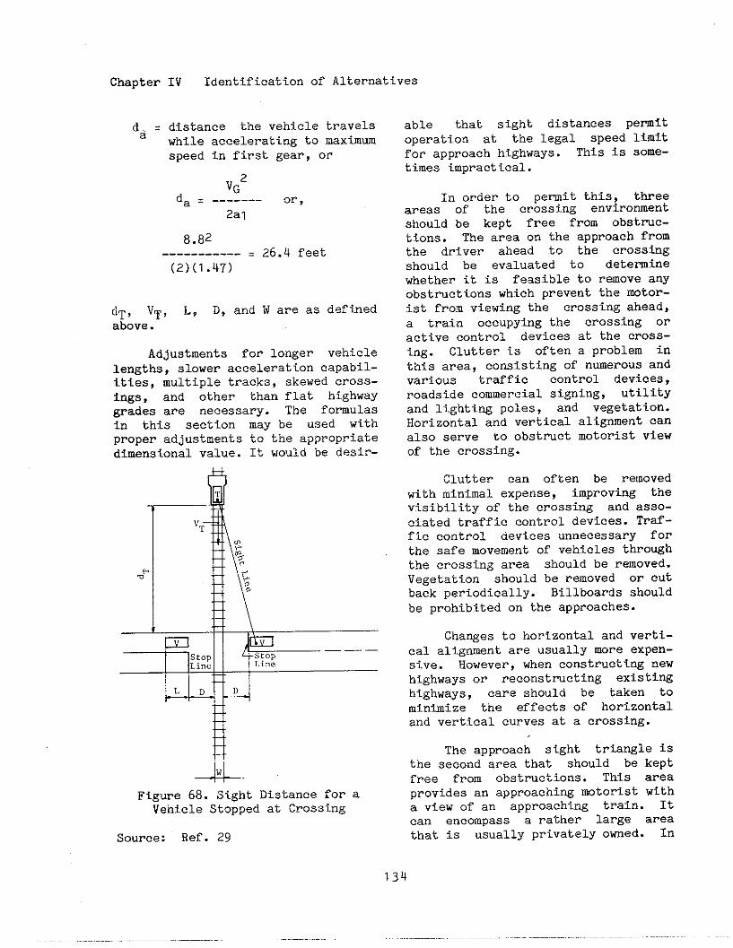
IV Identification of AlternativesChapter
da = distance the vehicle travelswhile accelerating to maximumspeed in first gear, or
VG2da = ------- or,
2al
a.a2---------- = 26.4 feet(2)(1.47)
dT, VT, L, D, and W are as definedabove.
Adjustments for longer vehiclelengths, slower acceleration capabil-ities, multiple tracks, skewed cross-ings, and other than flat highwaygrades are necessary. The fo~ulasin this section may be used withproper adjustments to the appropriatedimensional value. It would be desir-
A
I B\
BA
Figure 6a. Sight Distance for aVehicle Stopped at Crossing
Source: Ref. 29
able that sight distances Pe~itoperation at the legal speed limitfor approach highways. This is sOme-times impractical.
In order to pemit this, threeareas of the crossing environmentshould be kept free from obstnc-tions. The area on the approach fromthe driver ahead to the CrOSSingshould be evaluated to deteminewhether it is feasible to remove anyobstructions which prevent the mtor-ist from viewing the crossing ahead,a train occupying the crossing oractive control devices at the cross-ing. Clutter is often a problem inthis area, consisting of nmerous andvarious traffic control devices,roadside commercial signing, utilityand lighting poles, and vegetation.Horizontal and vertical alianment canalso serve to obstruct mot~rist viewof the crossing.
Clutter can often be removedwith minimal expense, improving thevisibility of the crossing and asso-ciated traffic control devices. Traf-fic control devices unnecessary forthe safe movement of vehicles throughthe crossing area should be relnoved.Vegetation should be removed or cutback periodically. Billboards shouldbe prohibited on the approaches.
Changes to horizontal and verti-cal alignment are usually more expen-sive. However, when constricting newhighways or reconatrueting existiwhighways, care should be taken tominimize the effects of horizontaland vertical curves at a crossing.
The approach sight triangle isthe second area that should be keptfree from obstmctions. This areaprovides an approaching mtorist witha view of an approaching train. Itcan encompass a rather large areathat is usually privately owned. In

Chapter IV Identification of Alternatives
rural areas, this sight triangle maycontain cropg or fam equipment thatblock the motorist1s view. For thisreason, clearing the sight trianglemy be cliffieult to achieve. How-ever, obstructions should be removed,if possible, to allow vehicles totravel at the legal speed limit forthe approach highway. Vegetation canbe removed or cut back periodically,billboards and parking should be pro-hibited, and small hills my beregraded.
The third area of concern is thetrack sight distance, or the areaalong the track. Usually, this areais located on railroad right-of-way.Vegetation is often desired alongrailroad right-of-way to serve as anenvironmental barrier to noise gener-ated from train movements. However,the safety concern at crossings is ofmore tiportance and, if possible,vegetation should be removed or cutback periodically. Also, if practi-cal, this sight distance area shouldbe kept free of parked vehicles andstanding railroad cars. Care shouldbe taken to avoid the accumulation ofsnow in this area.
An engineering study, asdescribed in Chapter III, should beconducted to determine if the threetypes of sight distance can be pro-vided as desired. If not, otheralternatives should be considered.The highway speed might be reduced,either through the installation of anadvisory or regulatory speed sign, toa level which confoms with theavailable sfght distance. It iSimportant that a motorist understandwhy the speed reduction is necessary,otherwise, it may be ignored unlessenforced. At crossings with passivecontrol devices only, conaiderationmight be given to the installationof active traffic control devicesthat warn of the approach of a train.
2. Geometries
The ideal crossing geometry is a90 degree titersection of track andhighway with slight ascendi~ gradeson toth highway approaches to reducethe flow of surface water toward thecrossing. Few crossings have thisideal geometry because of topographyor llmitationa of right-of-way forboth the htghway and the railroad.Every effort ghould be mde to con-struct new crosstigs in this manner.Horizontal and vertical alignmnt andcross-sectional design are discussedbelow.
Horizontal Alignment. Desira-bly, the highway should titersect thetracks at a right angle with no near-by intersections or driveways. Thislayout enhances the driver’s view ofthe crossing aud tracks and reducesconflicting vehicular movements fromcrossroads and driveways. To theextent practteal, crosstigs shouldnot be located on either highway orrailroad curves. Roadway curvatureinhibits a driver’s view of a cross-ing ahead and a driver’s attentionmay be directed toward negotiatingthe curve rather than looking for atrain. Railroad curvature inhibits adriver’s view down the tracka fromboth a stopped position at the cross-ing and on the approach to the cross-ing. Those crossings that are locatedon botb. highway and railroad curvespresent matitenance problems and poorridability for highway traffic dueto conflicting superelevations. Sim-ilar difficulties arise when super-elevation of tl~etrack is oppositeto the grade of the highway.
If the intersection betweentrack and highway cannot be mde atright angles, the variation from gOdegrees should be minimized. OneState limits the minimm skew to 70degreea. At skewed crossings, motor-

Chapter IV Identification of Alternatives
ists must look over their shoulder toview the tracks. Because of thismore awkward movement, some motoristsmay only glance quickly and not takethe necessary precaution.
Generally, improvements to hori-zontal aligment are expensive. Spe-cial consideration should be given tocrossings that have complex horizon-tal geometries as described above.These crossings may warrant theinstallation of active traffic cOn-trol systems or, if possible, may beclosed to highway traffic.
Vertical Alignment. It is desir-able that the intersection of high-way and railroad be mde as level aspossible from the standpoint of sightdistance, ridability, and j brakingand acceleration df.stances. Drainagewould be improved if the crossingwere located at the peak of a 10ngvertical curve on the highway. Ver-tical curves should be of sufficj.entlength to insure an adequate view ofthe crossing.
Track maintenance can result inraising the track as new ballast isadded to the track structure. Unlessthe highway profile is properlyadjusted, this practice results in a‘ihmped!icrossing that may adverselyaffect safety and operation of high-way traffic over the railroad. Hmpedcrossings can be of particular con-cern for vehicles with low under-clearances, e.g. “low-boy” trucks.It is possible for these trucks tobecome caught on the tracks, obvious-ly causing a hazard.
Alternatives to this probleminclude a design standard that dealswith maximum grades at the crossing,prohibiting truck trailers with acertain combination of underclearanceand wheelbase to cross the crossing,
setting trailer design standards, orminimizing the rise in track due tomaintenance operations.
Some States have addressed thisissue by setting standards. The Illi-nois Commerce Commission specifiesthat From the outer rail of the out-ermost track, the road surface shouldbe level for about 24 inches. Fromthere to a distance of 25 feet, amaximum grade not to exceed one per-cent is specified. From that pointto the railroad right-of-way line,the maximum grade is five percent.
The West Virginia Department ofHighways recommends that when a trackraise of one tnch or more is neces-sary, the approach pavement should betapered at a rate of not less than 10feet per one inch of track raj.se.The pavement immediately adjacent tothe outermost rail should be levelfor a minimw distance of three feet.
The Florida Department of Trans-portation (DOT) has initiated a sur-vey of crossings on the State h~.ghwaysystem to determine if a particularcrossing profile will accommodate lowbed vehicles that meet State roadclearance requirements. The FloridaDOT has identified seven differentprofile types and co~respondingtables to be used in the determin-ationof adequate profiles.
The “AmericanRailway EngineeringAssociation (AREA) Manual for RailwayEngineering recommends that thecrossing surface be in the same planeas the top of rails for a distance oftwo feet outside of rails and thatthe surface of the highway be notmore than three inches higher nor sixinches lower than the top of nearestrail at a point 30 feet from the railunless track superelevationdictatesotherwise.
136
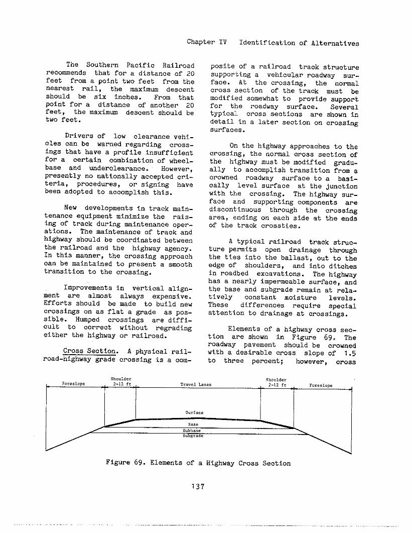
Chapter IV Identification of Alternative:;
The Southern Pacific Railroadrecommends that for a distance of 20feet from a point two feet from thenearest rail, the maximom descentshould be six inches. From thatpoint for a dtstance of anothe~ 20feet, the maximw descent should betwo feet.
Drivers of low clearance vehi-cles can be warned regarding cross-ings that have a profile insufficientfor a certain combination of ~heel-base and underclearance. However,presently no nationally accepted cri-teria, procedures, or signing havebeen adopted to accomplish this.
New developments in track main-tenance equipment minimize the rais-ing of track during maintenance oper-ations. The maintenance of track andhighway should be coordinated betweenthe railroad and the highway agency.In this manner, the crossing ~PProachcan be maf.ntainedto present a s~Othtransition to the creasing.
Improvementa in vertical align-ment are almst always expensive.EffOrts should be made to build newcrossings on as flat a grade aa pos-sible. Hmped crossings are diffi-cult to correct without regradingeither the highway or railroad.
Cross Section. A physical rail-road-highway grade crossing is a com-
posite of a railroad track structm<?supporting a vehicular roadway sur..face. At the crossing, the nomal.cross section of the track must b<!modified somewhat to provide support,for the roadway surface. Several,typical, cross sections are shown irIdetail tn a later section on crossingsurfacea.
On the highway approaches to thecrossing, the normal cross section orthe highway must be modified gradu-ally to accomplish transition from acrowned roadway surface tO a basi-cally level surface at the junctiOnwith tk!e crossing. The highway sur-face and supporting com~nents arediscontinuous through the crosstigarea, ending on each side at the endsof the track crossties.
A typical railroad track st~c-ture pemits open drainage throughthe ties into the ballast, Out to theedge of shoulders, and into ditchesin roadbed excavations. The highwayhas a nearly impermeable surface, andthe base and subgrade remain at rela-tively constant moisture levels.These dl.fferences require specialattention to drainage at crossings.
Elements of a highway cross sec-
tiOn are shown in Figure 69. Theroadway pavement should be crownedwith a desirable crOss slope of 1.5to three percent; however, cross
Shoulder Shoulder
Figure 69. Elements of a Highway Cross Section
137
,.
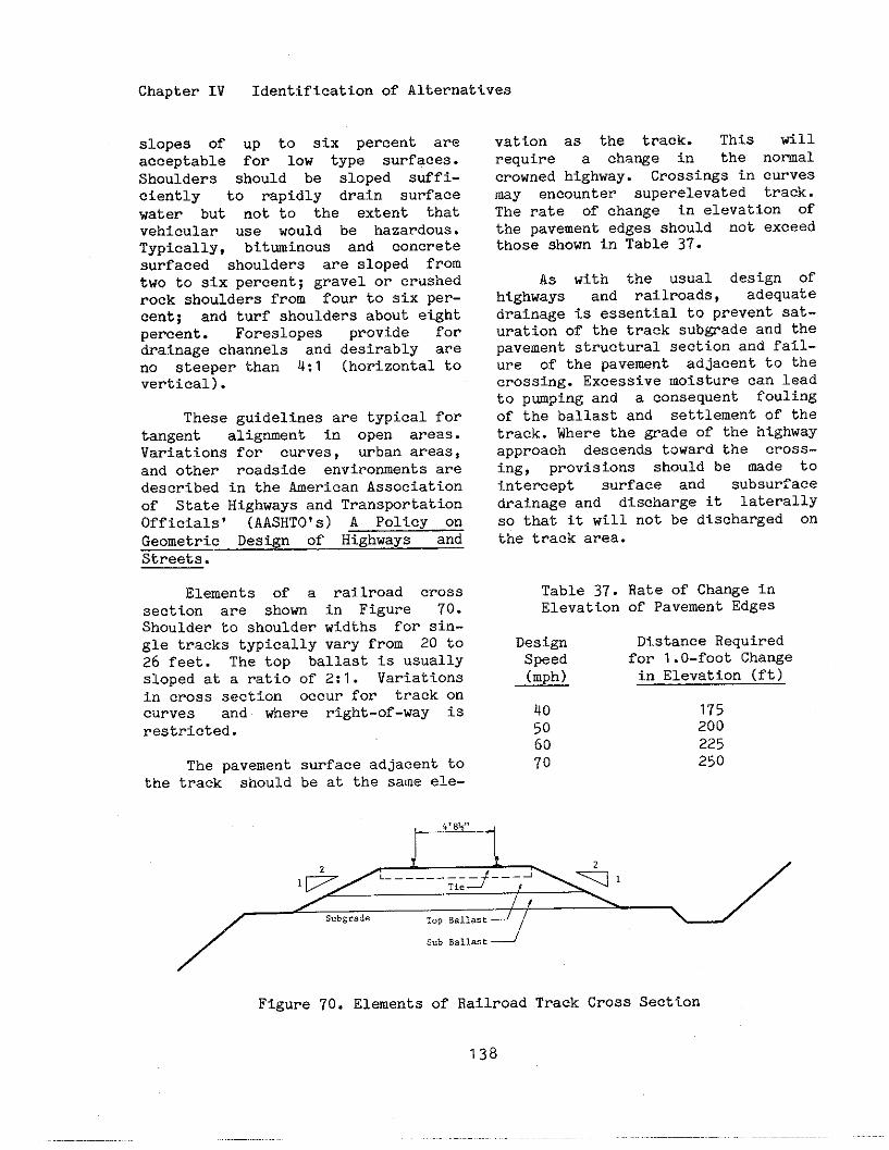
Chapter IV Identification of Alternatives
slopes of up to six percent areacceptable for low type surfaces.Shoulders should be sloped Suffi-ciently to rapidly drain surfacewater but not to the extent thatvehicular use would be hazardous.Typically, bitwinous and concretesurfaced shoulders are sloped fromtwo to six percent; gravel or crushedrock shoulders from four to six per-cent; and turf shoulders about eightpercent. Foreslopes provide fordrainage channels and desirably areno steeper than 4:1 (horizontaltovertical).
These guidelines are typical fortangent alignment in open areas.Variations for curves, urban areas,and other roadside environments aredescribed in the American Associationof State Highways and TransportationOfficials’ (AASHTO’s) A POliCY OnGeometric Design of Highways andStreets.
Elements of a railroad crosssection are shown in Figure 70.Shoulder to shoulder widths fOr sin-gle tracks typically vary from 20 to26 feet. The top ballast is usuallysloped at a ratio of 2:1. Variationsin cross section occur for track oncurves and where right-of-way isrestricted.
The pavementthe track should
surface adjacent tobe at the same ele-
vation as the track. This willrequire a cha~e in the nomalcrowned highway. Crossings in curves
~Y encOunter Superelevated track.The rate of change in eleVatiOn Ofthe pavement edges should not exceedthose shown in Table 37.
AS with the usual design ofhighways and railroads, adequatedrainage is essential to prevent sat-uration of the track sub~ade and thepavement structural section and failu-re of the pavement adjacent to thecrossing. Excessive moisture can leadto pmping and a consequent foulingof the ballast and settlement of thetrack. Where the grade of the highwayapproach descends toward the crOss-ing, provisions should be mde tointercept surface and subsurfacedrainage and discharge it laterallYso that it will not be discharged onthe track area.
Table 37. Rate of Cha%e inElevation of Pavement Edges
Design Distance RequiredSpeed for 1.O-foot Change(mph) in Elevation (ft)
40 17550 20060 22570 250
/
Figure 70.
SubBallast
Elements of Railroad Track Cross Section
138
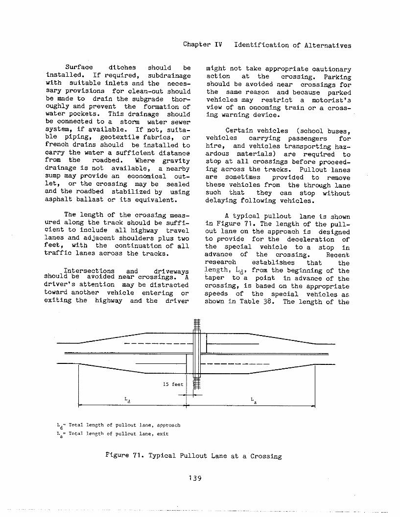
Chapter IV Identification of Alternatives
Surface ditchesinstalled. If required,with suitable inlets and
should besubdrainagethe neces-
sary provisions for clean-out shouldbe made to drain the subgrade thor-o~hly and prevent the formtion ofwater pockets. This drainage shouldbe connected to a storm water sewerSystem, if available. If not, suita-ble piping, geotextile fabrics, orfrench drains should be installed tocarry the water a sufficient distancefrom the roadbed. Where gravitydrainage is not available, a nearbysump may provide an economical Out-let, or the crossing may be sealedand the roadbed stabilized by usingasphalt ballast or its equivalent.
The length of the crosstig meas-ured along the track should be suffi-cient to include all highway travellanes and adjacent shoulders plus twofeet, with the continuation of alltraffic lanes across the tracks.
Intersections and drivewaysshould be avoided near crossings. Adriver’s attention may be distractedtoward another vehicle entering Orexiting the highway and the driver
might not take appropriate cautionaryaction at the crossing. Parkingshould be avoided near crossings fojrthe same reason and because parke,ivehicles may restrict a wtorist$ :Sview of an oncoming train or a crOss.-ing warning device.
Certain vehicles (school buses,,vehicles carrying passengers forhire, and vehicles transporting haz..ardous materials) are required t()StOp at all crossings before proceed..ing across the tracks. Pullout lanesare sometimes provided to remove?these rehicles from the through lanf?such ‘that they can stop withO”t,delaying following vehicles.
A typical pullout lane is showrlin Figwe 71. The length of the pull-.out lane on the approach is designedtO provide for the deceleration ofthe special vehicle to a stOP ir,advance of the crossing. Recent.research establishes that the!length, Ld,,from the beginning of the!taper to a point in advance of the!crossing, is based on the appropriatespeeds of the special vehicles asshown ~.nTable 38. The length of the
-— —— _____ Jill II
15feet
Ld La
Ld=TotallengthofPull.”clane,a~pro.chLa=TocallengthofPull.”t1...,exir
Figure 71. Typical Pullout Lane at a Crossing
139
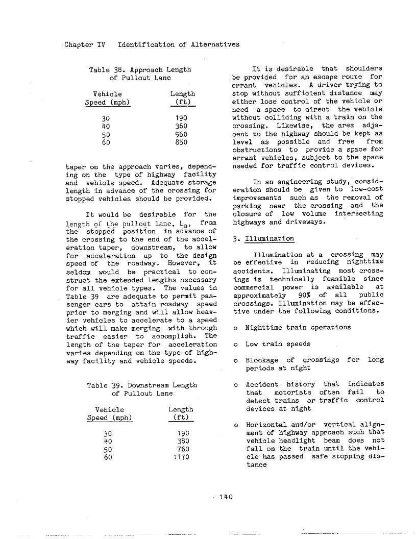
Chapter IV Identification of Alternatives
Table 38. Approach Lengthof Pullout Lane
Vehicle LengthSpeed (mph) (ft)
30 19040 36o
50 56060 850
taper on the approach varies, depend-ing on the type of highway facilityand vehicle speed. Adequate StOragelength in advance of the crossing forstopped vehicles should be provided.
It would be desirable for thelength gf ~he pulloq.tlane, La, fromthe- stopped position in advance ofthe crossing to the end of the accel-eration taper, downstream, to allowfor acceleration up to the designspeed of the roadway. However, itseldom would be practical to cOn-struct the extended lengths necessaryfor all vehicle types. The values inTable 39 are adequate to pemit pas-senger cars to attain roadway speedprior to merging and till allow heav-ier vehicles to accelerate to a speedwhich wil1 make merging with throughtraffic easier to accomplish. Thelength of the taper for accelerationvaries depending on the type of high-way facility and vehicle speeds.
Table 39. Downstream Lengthof Pullout Lane
Vehicle LengthSpeed (mph) (ft)
30 19040 38050 76060 1170
It is desirable that shouldersbe provided for an escape route forerrant vehicles. A driver trying tostop without sufficient distance mayeither lose control of the vehicle orneed a space to direct the vehiclewithout colliding with a train on thecrossing. Likewise, the area adja-cent to the highway should be kept aslevel as possible and free fromobstructions to provide a space forerrant vehicles, subject to the spaceneeded for traffic control devices.
In an engineering study, consid-erateion should be given to low-costImprovements such as the removal ofparki~ near the crossing and theclosure of low volme intersectinghighways and driveways.
3. Illumination
Illumination at a crossing mayhe effective in reduci~ nighttimeaccidents. Illminattng most crOss-ings is technically feasible sincecommercial power is available atapproximateely 90% of all publiccrossings. Illminatton may be effec-tive under the followi~ conditions.
0
0
0
0
0
Nighttime train operations
Low train speeds
Blockage of crossings for longperiods at night
Accident history that indicatesthat motorists often fail todetect trains or traffic controldevices at night
Horizontal and/or vertical align-ment of highway approach such thatvehicle headlight beam does nOtfall on the train until the vehi-cle has passed safe stopping dis-tance
Chapter IV Identification of Alternatives
o Long dark trains, e.g. unit coaltrains
o Restricted sight or stopping di~-tance in rural areas
o Humped crossings where oncomingvehicle headlights are visibleunder train
o Low ambient light levels
o A highly reliable source of power
Recommendations for the place-ment and type of luminaires areavailable in the F~A !s RoadwayLighting Handbook and the Illuminat-ing Engineering Society1s AmericanNational Standard Practice for Road-way Lighting. It is desirable thatat least two luminaires be provided,one on each side of the tracks,
On uncurbed roadways, luminairesupports should be erected as far aspractical from the traveled way,desirably outside the clear zone.men located within the clear zone,
defined in the Guide for SelectingtLocating, and Designing Traffic Bar-riers, luminaire supports should havebreakaway bases. If possible, lumi-naires should also be located toensure damaged poles will not fall onthe tracks. A distance of 25 tO 50feet from the nearest track is recom-mended.
Mounting height should be in therange of 30 feet to 40 feet. It ispreferable that the illumination bedistinctive in color, volume, or dis-tribution so that it clearly distin-guishes the crossing among otherstreet lighting.
The Oregon Public Utility Com-mission? recommends that thereshould be at least one foot-candle ofaverage maintained illumination on a
vertical planes five feet from thecenterline of the track. The lumi-naires should be oriented toward therailroad. Maximum permissible levelof illumination and exact orientationof the luminaires should be deter-mined on a case-by-case basis an.ishould consider site conditions anithe level of ambient nighttime illu-mination. Ideally, luminaires shoul,iilluminate an area along the trackthat is 50% longer than the width ofthe road. Illumination should extendto approximately 15 feet ab~~e th~top of rail.
The luminaires should be posi.-tiOned to ensure that a motorist o::railroad operator is not subjected toglare from the light source. 1:?glare cannot be eliminated, cutOffsmay be provided to shield the cone o~?vision of a motorist or locomotiveengineer. In rural areas with hightrain speeds, some lighting should b(?
directed dow the tracks to illumi..nate the sides of an approachingtrain. Trains, traffic control.devices, or signs should not be over..powered by ~ackground objects orlighting.
Train activated illuminatiorlcircuitry can be designed, but shouldnot be used as a substitute foractive traffic control systems.
4. Shielding Supports for Traffic:Control Devices
The purpose Of a traffic bar-rier, such as a guardrail or crash,cushion, is to protect the motoristby redirecting or containing anerrant vehicle. The purpose is nottO protect a traffic control deviceagainst collision and possible dam-age. Their use should be limited tosituations where hitting the object,i.e. a traffic control device, ismore hazardous than hitting the traf-
Chapter IV
fic barrierthe vehicle
Identification of Alternatives
and possibly redirectinginto a train.
A longitudinal guardrail shouldnot be used for trtifie centroldevices at crossings unless theguardrail is otinerwisewarranted, asfor a steep embantient. The reasonfor not using a longitudinal guard-rail is that it might redirect avehicle into a train.
On some crossings, it may bepossible to use crash cushions toprotect the motorist from striking atraffic control device. Some crashcushions are designed to capture,rather than redirect a vehicle, andmay be appropriate for use at crOss-ings to reduce the redirection of avehicle into the path of a train.
The ring type guardrail placedaround a signal mast may create thesae type of hazard as the signalmast itself, i.e. the guardrail mybe a roadside obstacle. They do how-ever serve to protect the signalmast. Since functioning devices arevital to safety, the ring type guard-rail may be used at locations withheavy industrial traffic, such astrucks, and low highway speeds.
When a barrier is used, itshould be installed according to therequirements In the Guide for Select-ing, Locating and Designing TrafficBarriers.
Flaggi~5.
At certain crossings, railroadcompanies may have a policy to use aflagger to stop highway vehicles andpedestrians before allowi~ a trainto move over the crossing. Thesecrossings typically have only passivewarning signs. Flaggers should beemployed at crossings which do not
have active control devices when therailroad cars are not headed by anengine. Some railroad companiesrequire flagging when the train hasbeen split or when switching opera-tions necessitate numerous movementsacross the roadway.
6. Miscellaneous Improvements
There are several other siteimprovements that can be mde toenhance safety and operations atrailroad-highway grade crossings.One of the alternatives is crossingclosure, as discussed in an earliersection.
Prolonged blockage of crossfigsas a result of low train speeds ornumerous switchi.ng movements canadversely affect crossing safety andoperations. Increased vehicular delaynot only affects operations but mayalso affect safety if emergency vehi-cles cannot respond to a life-threat-ening situation. Train speeds mightbe increased by upgrading the trackclass, removing local speed restric-tions, and improving crossings tocompensate for local concerns regard-ing the safety of higher speedtrains. Crossings located on track-age that has nmerous switching move-ments should be closed, if possible.If not, switches might be relocatedor switching operations might be re-scheduled at times other than peakhighway traffic periods. Establish-ing “hotlines,,between emergency ser-
vices and the railroad can assist therailroad in opening blocked crossingsto allow emergency vehicles accessacross the tracks. Sidings might beextended to allow space for storageof railroad equipment away fPorncrossings. Rail operations, such astrain crew changes and refuelingpoints, might be relocated outside ofcowunities.

Chapter IV Identification of Alternatives
Exposure between trains andgchool buses, commercial buses, andvehicles transporting hazardous mte-rials should be minimized because ofthe potential catastrophic conse-quences. These types of vehiclesmight be rerouted tO avOid crossingthe railroad at-grade, if possible.If not, these vehicles may traversethe railroad at crossingg with activetraffic control devices.
Traffic divisional islands maybe used at crossings on multi-laneroadways to prevent motorigts fromdriving around a lowered gate. Traf-fic divisional islands are narrowelongated iglands that follow thecourse of the highway to separateconflicting traffIc movements.
An engineering study should beconducted to determine if trafficdivisional islands are appropriate.The study should consider the acci-dent history of the crossing, driverresponse to lowered gates, trsin andhighway traffic volumes and condi-tions, need for upgraded train detec-tiOn Systems, and crossing apprOachgeometry. Consideration should begiven to the potential hazard of theisland itself.
Islands must extend far enoughback from the crogsi~ to accommodatetraffic queueg and should not havecut-outs for access and egress oflocal traffic. The pavemant mayrequire wideni~ to retain mintiumlane widths. Vertical transit:lonsonthe raised igland approaches shouldbe treated similar to curbed goreareas. Delineators might be placed onthe raised island to aid snow plowi~operations.
The ends of the island should beprotected as other traffic islands,to provide a maximum degree of warn-
ing of the presence of the island anda definite indication of the propervehicle path or paths to be followed.
Comprehendive planni~ is essen-tial to avoid future crossi~ prob-lems. Community development shouldbe planned to avoid crossings at-grade.
E. Crossing Stiaces
This portion of the handbOOkprovides general information of cur-rently available types of crossingsurfaces. The use of trade names andthe identification of manufacturersand distributors are solely fOr theconvenience of the reader. Such useand identification do not constitutean OffiCial endorsement by the U.S.Department of Transportation of anyproduct to the exclusion of othersthat may be suitable.
As a vehicle moves across arailroad-highway grade crossing, themterial on which its tires roll iscommonly referred to as a crossingsurface. It is supported by therailroad track structure, primrilythe crossties, which in turn trans-fers the highway load, as well asthe train load, through the ballastto the uderlying sub~ade.
For railroads, the crossing sur-face and the highway approach pave-ments leading up to the crossing con-fine the track structure and createdrainage and maintenance problms.
Fo]ehighway authorities, cross-ings create discontinuity in the nor-mal highway surface, which at bestresults in somewhat poorer ridingquality and may result in increasedvehicle operating costs, hazard, andinconvenience to highway traffic.
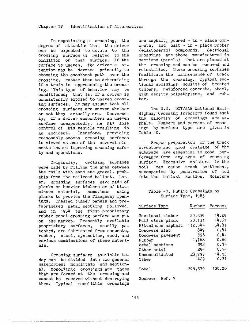
Chapter IV Identification of Alternatives
In negotiating a crossing, thedegree of attention that the drivercan be expected to devote to thecrossing surface is related to thecondition of that surface. If thesurface is uneven, the driver’s at-tention may be devoted primsrily tochoosing the smoothest path over thecrossing, rather than to detemini~if a train is approaching the cross-ing. This type of behavior may beconditioned; that is, if a driver isconsistently exposed to uneven cross-ing surfaces, he may assume that allcrossing surfaces are uneven whetheror not they actually are. Converse-ly, if a driver encounters an unevensurface unexpectedly, he may losecontrol of his veh%cle resulting inan accident. Therefore, provtdingreasonably smooth crossing surfacesis viewed as one of the several ele-ments toward improving crossing safe-ty and operations.
Originally, crossing suri”aceswere made by filling the area betweenthe rails with sand and gravel, prob-ably from the railroad ballast. Lat-er, crossing surfaces were made ofplanks or heavier timbers or of bitu-minous material, sometimes usingplanks to provide the flangeway open-ings. Treated timber panels and pre-fabricated metal sectf.ons followed,and in 1954 the first proprietawrubber panel crossing surface was puton the msrket. Presently availableproprietary surfaces, usually pa-tented, are fabricated from concrete,rubber, steel, synthetics~ wood, andvarious combinations of these materi-ala.
Crossing surfaces available to-day can be divided !nto two generalcategories: monolithic and section-al. Monolithic crossings are thosethat are formed at the crossing andcannot be removed without destroyingthem. Typical monolithic crossings
are asphalt, poured - in - place con-crete, snd cast - in - place rubber(elastomeric) compounds. Sectionalcrossings are those manufactured insections (panels) that are placed atthe crosstig and can be ~emoved andreinstalled. These crossing surfacesfacilitate the maintenance of trackthrough the crossing. Typical sec-tional crossings consist of treatedtimbers~ reinforced conc~ete, steel,high dens+.typolyethylene, and rub-ber.
The U.S. DOTIAAR National Rail-Highway Crossing Inventory found thatthe majority of crossings are as-phalt. Nmbers and percent of cross-ings by surface type are given inTable 40.
Proper preparation of the trackstructure and good drainage of thesubgrade are essential to good per-formance fro.n any type of crossingsurface. Excessive moisture in thesoil can cause track settlement,accompanied by penetrat+.on of mudinto the ballast section. Moisture
Table 40. Public Crosstngs bySurface Type, 19a3
Surface Type
Sectional timberFull width plankBituminous asphaltConcrete slabConcrete pavementRubberMetal sectionsOkher metalUnconsolidatedOther
Total
Source: Ref. 7
Nwber Percent
29,339 14.2930,131 14.67
112,544 54.81849 0.4?896 0.44
1 ,76a o.a6292 0.14294 0,14
28,797 14.03u2g 0.21
205,339 100.00
Chapter IV Identification of Alternatives
can enter the subgrade and ballastaeotion from above, below and/oradjacent subgrade areas. To the ex-tent feaaible, surface and subsurfacedrainage should be intercepted anddischarged away from the crossing.Drai~ge can be facilitated by estab-lishing an adequate difference inelevation between the crossing sur-faces and ditohes or embantientslopes. The highway profile at allcrossings should be such that waterdrains away from the crossing.
In sltuattons where the grade ofthe highway approach descends towardthe crossing, provisions should bemade to intercept sur~ace and subsur-face drainage and discharge it later-ally so thak it will not be dis-charged on the track area. Surfaceditches should be installed, If re-quired, subdraimge with suitableinlets and the necessary provisionsfor clean-out should be made LO drainthe subgrade and prevent the forma-tiOn of water pockets. This drainageshould be connected to a storm waterdrainage system, if available; ifnot, suitable piping~ geotextile fab-rics and/or french drains should beinstalled to carry the water a suffi-cient d?stance from the roadbed.Where gravity drainage is not avail-able, a nearby S~P may QPOVlde aneconomical outlet, or the crossingmay be sealed and the roadbed stabi-lized by using asphalt ballast or itsequivalent.
Sfnce drainage is more of aproblem in multitrack ter?itory, theinstallation of catch basins betweentracks at the ends of a crossingshould be considered. Any lag bolt,drive spike or track spike holes inthe ties should be filled and sealedto prevent entrance of moisture thatcauses early deterio?atf.on of theties.
It is desirable that the sub-grade be cleaned of all old contami-nated ballast and bladed tO a levelsurface. Selected subgrade materialshould be placed in layers no morethan 12 inches thick, then thoroughlycompacted by approved methods. Sub-grade material may consist of selectsoils~ soil cement, or asphaltic mix-es, to be selected by the individualrailroad.
Use of a suitable filter fabricover tbe entire subgrade area underthe crossing and for a sufficientdistance beyond can be a significantaid in separation~ fIltration, watertransport, and tensile reinforce-ment. The fabric separates tihebal-last from the subgrade, and thusrestricts ballast penetration downinto the subgrade and prevents con-tami~tion of the ballast from theflow of soft sub~ade material intothe ballast layer through pumpingaction caused by heavy train loads.Fabrics also provtde additionalstructural support at the ballast-subgrade interface such that loadsare spread over a greater area.
Numerous stabilization fabricaare available from several manufac-turers and are useful in a variety ofcivil engtieeril~gfunctions involvi~tiprovements in drainage and reten-tion of fine soil particles. Thesefabrics are made of polymers; someare woven but uny non-woven ones areproduced by spunbonding or by felt-ing. These fabrics are also called“engineering fabrics” or ‘iplasticfilter fabrics’!. However, the termstabilization fabrics better charac-terizes their function in highway andrailroad applications where abrasionresistance and tensile strength underheavy loads are quite important.Some of the available products arelisted in Table 41.
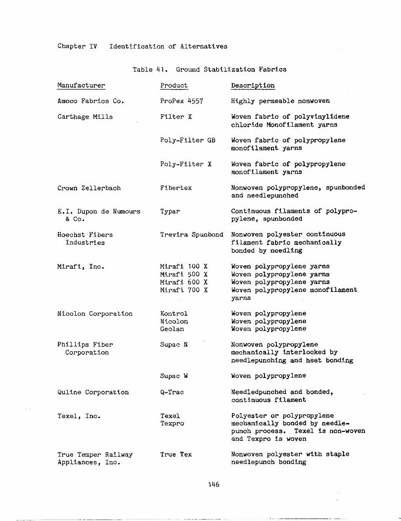
Chapter IV Identification of Alternatives
Table 41. Ground Stabilization Fabricg
Manufacturer
Amoco Fabricg Co.
Carthage Mills
Crown Zellerbach
E.I. Dupon de Nmows& co.
Hoechst FibersIndustries
Mirafi, Inc.
Nicolon Corporation
Phillips FiberCOrpOration
Quline Corporation
Texel, Inc.
True Temper RailwayAppliances, Inc.
Product
PrOPex 4557
Filter X
Poly-Filter GB
Poly-Filter X
Fibertex
Typar
Trevira Spunbond
Mirafi 100 XMirafi 500 XMirafi 600 XMirafi 700 X
KontrolN<colonGeolan
Supac N
Supac w
Q-Trac
TexelTexpro
True Tex
Description
Highly permeable nonwoven
Woven fabric of polyvinylidenechloride Monofilament yarns
Woven fabricmonofilament
Woven fabricmonofilament
of polypropyleneyarns
of polypropyleneyarns
Nonwoven polypropylene, gpunbondedand needlepunched
Continuous filament9 of polypro-pylene, spunbonded
Nonwoven polyester continuousfilment fabric mechanicallybonded by needli~
Woven polypropylene yarnsWoven polypropylene yarnsWoven polypropylene yarnsWoven polypropylenemonofilamentyarns
Woven polypropyleneWoven polypropyleneWoven polypropylene
Nonwoven polypropylenemechanically titerlocked byneedlepunchi~ and heat bonding
Woven polypropylene
Needledpunched and bonded,COUtinUOUS fil~nt
Polyester or polypropylenemechanically bonded by needle-punch procesg. Texel is non-wovenand Texpro is woven
Nonwoven polyester with stapleneedlepunch bonding
146
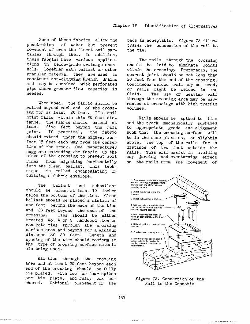
Chapter IV Identification of Alternatives
Some of these fabrics allow thepenetration of water but preventmovement of even the finest soil par-ticles through them. In addition,these fabrics have various applica-tions in below-grade drainage chan-nels. Together with ballast or othergranular material they are used toconstruct non-clogging French drainsand may be combined with perforatedpipe where greater flow capacity isneeded.
When used, the fabric should berolled beyond each end of the cross-ing for at least 20 feet. If a railjoint falla within this 20 foot dis-tance, the fabric should extend atleast five feet beyond the railjoint. If practical, the fabricshould extend mder the highway sur-face 15 feet each way from the centerline of the track. One manufacturersuggests extending the fabric up thesides of the crossing to prevent soilfines from migrating horlzontallyintO the clean ballast. This tech-nique is called encapsulating orbuilding a fabric envelope.
The ballast and subballastshould be clean at least 10 inchesbelow the bottoms of the ttes. Cleanballast should be placed a mimhm ofone foot beyond the ends of the tiesand 20 feet beyond the ends of thecrossing. Ties should be eithertreated No. Q or 5 hardwood ties orcOncrete ties through the crossingsurface area and beyond for a minfmwdistance of 20 feet. Length andspacing of the ttes should confom tothe type of crossing surface ~ateri-als being used.
All ties through the crossingarea and at least 20 feet beyond eachend of the crossing should be fullytie plated, with two or four spikesper tie plate, and fully box an-chored. Optional placement of tie
pads 2s acceptable. Figure 72 illus-trates the connectIon of the rail tothe tie.
The rails through the crossingshOuld be laid to ebinate jointswithin the crossing. Preferably, thenearest joint should be not less than20 feet from the end of the crossing.Continuous welded rail may be used,or rails might be welded in thefield. The use of heavier railthrough the crossing area may be ~ar-ranted at crossings with high trafficvolwes.
Rails should be spiked to line
and the track mechanically surfacedtO appropriate grade and aligmentsuch that the crossing surface willbe in the sme plane as, or slightlyabove, the top of the rails for adistance of two feet outside therails. This will assist in avoidingany jarring and overturning effecton the rails from the movement of
,,4,,s .“,,,,, ,,s ,.., ., ,,0
,“””!”, .,,s .;,, ,,,”.,..”8.,.,,., ..,.,1 .,.
Figwe 72. Connection of theRail to the Crosstie
Chapter IV Identlftcat%on of Alternatives
heavily loaded highway vehicles andwill aid in providing a smooth ridingsurface. In turnv the first two orthree inches of the top surface ofany non - plastic crossing surfacematertal immediately adjacent to theoutside of the head of a running railshould be lowered by clappingapproxi-mately one quarter inch, so that itwill not be damaged by contact withfalse flanges of railroad car wheelswith worn treads.
Following completl.on of theoriginal tamping, arrangements shouldbe made for rail traffic to move overthe track to induce any initial set-tlement, and the track should then beretamped to obtain optimum track sta-bility. This retamping should in-clude the area of the crosstng andextand one rail length past the near-est joint. In its final pOsf.tiOn,the top of the crossing surfaceshould be at the same elevation asthe top of the adjscent highway sur-face.
Flangeway openings on the insideof the running rails are provided invarious ways. Prefabricated section-al type surfaces make provision forflangeways in the desIgn and fabrica-tf.on of the individual sections. Inthe very simple monolithic bitminouscrossing surfaces, flangeways may beformed by placing a removable woodstrip adjacent to the head of therail and removing it after the sur-face has been compacted by rolling.This procedure is not recommended,except for crossings with very lightvehicular traffic. A more durableinner edge of the flangeway will beformed by using a 1ine of permanentlyfastened timbers or scrap railS.Constderatfon must be given to theimpact on track cireu$.tsand appro-priate Federal Railroad Administra-tion (FRA) rules. The flangewayopening should have a minimm widtin
of 2.5 inches and should extend atleast two inches below the top of therunning rails. Flangeway openingsand spaces outside the head of therunning rails should be sealed toreduce the flow of water into theballast and subgrade in the crossi~area.
The crossing length, measuredalong the track, should be sufficientto extend at least one foot beyondtha edge of the highway pavement, in-cluding any paved shoulders on thehighway approaches to the crossing.State laws may dictate that +.f hot-mix b+.tuminous asphalt pavement isused on the highway approaches, con-sideration should be given to instal-ling the pavement to at least thebottom of the tie elevation, placi~it in several layers, and rolling itparallel to the track with the finallayer rolled in both directions. Theends of the crossing surface shouldbe beveled to avoid dmage by drag-ging railroad equipment. MedianStr+.ps, shoulder escape routes, andsidewalks normlly should have thesame surface material installed toprovide one continuous crossing sur-face. In urban areas, separate sec-tions of crossings may be providedfor pedestrian use if sidewalks aresomewhat reInoved from the highway.However, unless adequate drainage isprovided, the unsurfaced pockets be-tween the separate crossing areas maycreate undesirable soft subwade con-ditions.
Proper preparation of subgradecannot be overemphasized. SevaralStates have experienced problems witincrossing surfaces that can be direct-ly related to inadequate subgradepreparation. Typical problas foudat crossings include the following.
o Replacement pavement failed(cracked and settled) in apron
148
Chapter IV Identificationof Alternative
area adjacent to crossing surfacebecauae of:
- inadequate compaction in apronarea (from ends of ties to ex-isting pavement) of subgrade,ballast, and pavement material;
- failure to install header boardwhen required;
- failure to fom pavement/crOss-ing relief joint;
- failure to seal pavement/crOss-ing relief joint; or,
- inadequate existi~ pa,rementremoved for crossing installa-tion, creating a space too nar-row to properly compact re-placement material. (Mintium of36 inches is recommended.)
o Frost heaving of pavement on high-way approaches.
o Improper establishment of highwaypavement and crossing surface ele-vations resulting in a nOn-uni-fOm transition and causing adecrease in riding comfort.
o Track settlement causing poortransition, and loose outside pan-els due to:
- Unstable subgrade (inadequateadvance investigation) or,
- Inadequate ballast depth and/orcompaction.
o Improper placement of filter clothand failure to place under track-bed.
Whenever either track resurfac-ing or highway resurfacing projectsinvolve a crossing, appropriate meas-urea should be taken to avoid detri-
mental effects to the serviceabilityof the crosstig surface. In tracksurfacing projects, the general trackraise should be tapered off in thearea approaching the crosstig so asnot to disturb the elevation of thecrossing. Or, the level of the en-tire crossing should be raised andgradual adjustments should be made inthe grade l?.neof the highway ap-proaches consistent with the profiledesign criteria for the class ofhighway involved. If more than onetrack is involved, the adjusted sur-face of the entire crossing shouldlie in one plane and all tracksshould be raised to correspond wtththe new elevation.
Caution must also be taken whenconstructing or maintaining crossingsurfaces in signalized track terri-tory. The rails must be kept insula-ted one from the other. Metal contactbetween the rails till shunt thetrack circuit and cauae signal fail-ures. Standing water fn the crossingarea may also shwt the circuit.
In highway resurfacing projects,the crossing surface should beraiaed, if necessary, to avoid creat-ing a pocket that till increase theflow of surface drainage into thecrossing area. Track raises shouldbe msde where necessary to accommo-datee the highway grade adjustment.Also, highway agencies should raiseapproaches where necessary to accom-modate track made adjustments.
Proper liasion should be estab-lished between railroad and highwayauthorities so that plans and sched-uling of work can be coordinated toavoid the planning or execution ofwork on either the highway or rail-road that might adversely affect thegrade line of the other. This isespecially true for removing snowfrom the crossing surface. Removal of
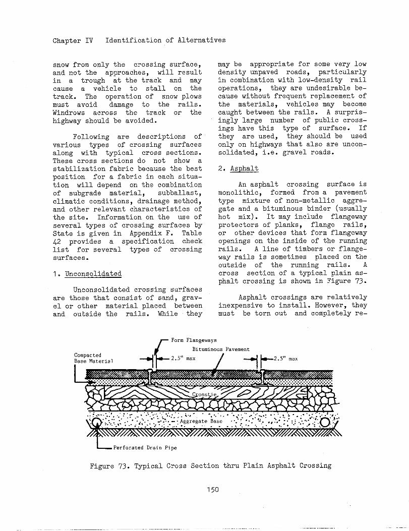
Chapter IV Identification of Alternatives
snow from only the crossing surface,and not the approaches, will resultin a trough at the track and maycause a vehicle to stall on thetrack. The operation of snow plowsmust avoid damage to the rails.Windrows across the track or thehighway should be avoided.
Following are descriptions ofvarious types of crossing surfacesalong with typical cross sections.These cross sections do not show astabilization fabric because the bestposition for a fabric in each situa-tion will depend on the combinationof subgrade material, subballast,climatic conditions, drainage method,and other relevant characteristics ofthe site. Information on the use ofseveral types of crossing surfaces byState is given in Appendix F. Table42 provides a specification checklist for several types of crossingsurfaces.
1. Unconsolidated
Unconsolidated crossing surfacesare those that consist of sand, grav-el or other material placed betweenand outside the rails. While they
may be appropriate for soresvery lowdensity repaved roads, particularlyin combination with low-density railoperations, they are mdesirable be-cause without frequent replacement ofthe materials, vehicles may becomecaught between the rails. A surpris-ingly large number of public cross-ings have this type of surface. Ifthey are used, they should be usedonly on highways that also are uncon-solidated, i.e. gravel roads.
2. Asphalt
An asphalt crossing surface ismonolithic, formed from a pavementtype mixture of non-metallic aggre-gate and a bituminous binder (usuallyhot mix). It may include flangewayprotectors of planks, flange rails,or other devices that form flangewayopenings on the inside of the runningrails. A line of timbers or flange-Way railS is sometimes placed on theoutside of the running rails. Across section of a typical plain as-phalt crossing is shorn in Figure 73.
Asphalt crossings are relativelyinexpensive to install. However, theymust be torn out and completely re-
~Perfor.ted DrainPipe
Figure 73. Typical Cross Section thru plain Asphalt CrOssing
150
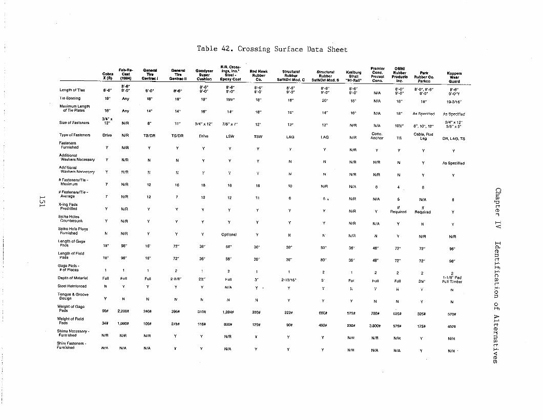
Table 42. Crossing Surface Data Sheet
*3
~a
Any
Any
N/R
N,R
M,R
Nm
N(R
N/R
N(R
N/R
M,R
N/R
w
se
f,.,,
“
N
2,2W
~+.
,8,
,4
~
TS,DR
Y
N
N
,2
12
Y
Y
“
Iv
,6
F.,,
Y
N
.,.N/A
N,,
N/A
c.”.,An.,.,
Y
N(R
N/R
8
N/A
Y
N/A
N
,8
,6
2
,.,,
Y
N
7m#
3,m#
N/R
N/A
,6
,6
N,R
NIB
.,6
N(R
N(R
N,A
N(R
N/R
N,R
N(R
3&
36
1
f“,,
.
“
575,
2m#
N,.
N/R
,9-3,,6
A, SPe.ified
3,WX ,25/8 x5
0,)”. D., LAG, TS
“
As Spmiti.d
v
Y
Y
Y
18
,2
Y
Y
Y
36
3W
,
*W,
“
N
3,0#
,,W
“
Y
Y
,
Y
?8
,,
Y
Y
Y
36
3?
1
~
“
N
32w
N/R
~v
58
2
f.,,
./,
N
1,Ow
N
570,
m,”
N/R
39,, 222, es,”
1,W IW
N/R
275,
Y
“
1,5# 9W
“
Y
4m# 575#
N/R
N(A
.,.
N,A
Y
Y
Y
vN/A
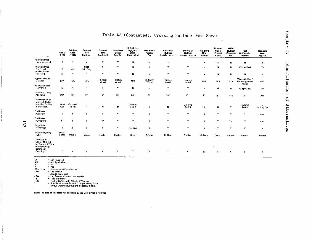
Table 42 (Continued).Crossing Surface Data Sheet
Fab-Ra. Genera,cobra C*8, ,,,.x(R)(,9,,)Gent,,. ,
C.”Pad, incenter., x.ingb.R,..”,, w,,outRemovingBalance ofcrossing?
YN
Y N/R
N.
N/A .,.
N.
,o~ 22.
Field Order.,c“, T.n,
““
“. Y
Y“St,.,,.F... M.,,!.
““
“Held
%,.0.,,.
.,.
.
,5.
N
Y
Y
“
Rubber
Y
YDR o,LAG.;;W
TS W
rD,,”,,..
=“e,=w,,,., HeadD,,”,spike,=LagScrew,=A, addlti..a,.0,,=Lag Screws .,,, Ati,ched washer= mmber screw.= Tmberscrews.),, A,,,.h.d W,,,er,=SP..ifl..ts..sare f., R.R.C.Su,.r Heavy DutyModel.other Ught.r weigh,mod.,,avail,,,,.
Y,
“
RUbb.r,wood
Y
30~
N
Y
,
Y
Rubber
“
NN
N
.,,
N
,o~
O;:;d
Y
Y
.,,0...
s,.,,
“
Y Y Y N
Y , Y N
Y ““ Y N
,Vbbe,, Rubber, R.,,,,, ~,,wood wood Wood
, “ Y
9* 30° 1,. 9*
Orde,.d“ N TO ., Y
Y Y “ “
Y “ Y “
Y Y Y Y
s“bbe, ..,,., RUbber Rubber
Y “ Y N
NN
M
N,A
N
6,
.
Y
Y
Y
con..
Y
N
A“y
Y
Y
Y.
Y
..,,,,
Y
K~~w.Guard
“Y.
N
.,,
.,.
A“,
,.C,O’Tc.,
.,.
.,.
,
mm,,,
Y
NoteThe,.,..“,,1s,abl..,s ..(lectedbytheu.,.. Pa.,,,.Ra,,coad
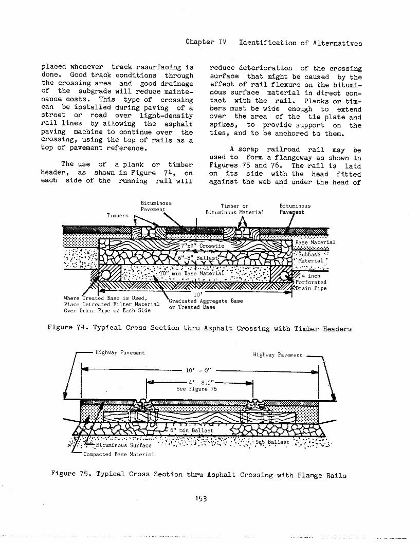
Chapter IV Identification of Alternatives
placed whenever track resurfacing i9done. Good track condition throughthe crossing area and good drainageof the gubgrade will reduce mainte-nance cogts. This type of crossingcan be installed during paving of astreet or road over light-densityrail lines by allowing the asphaltpaVing machine to continue over thecrossing, using the top of rails as atop of pavement reference.
The use of a plank or timberheader, as shown in Figure 74, oneach gide of the running rail will
reduce deterioration of the crossingsurface that might be caused by theeffect of rail flexure on the bitumi-nous surface Uterial in direct COn-tact with the rail. Planks or tim-bers must be wide enough to extendover the area of the tie plate andspikes, to provide support on theties, and to be anchored to them.
A scrap railroad rail may beused to form a flangeway as shown inFigures 75 and 76. The rail ~S laidon its side with the head fittedagainSt the web and under the head Of
Figure 74. Typical Cross SectiOn thru Asphalt Crossing with Timber Headers
- Compacted Base Material
Figure 75. Typical Cross SectiOn thru Asphalt Crossing with Flange Rails
153
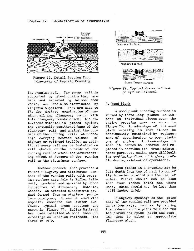
Chapter IV Identificationof Alternatives
W,um; no.,,, ,.”...”,
Figure 76. Detail Section ThruFlangeway of Asphalt Crossing
the running rail. The scrap rail issupported by steel chairs that aremade and mrketed by Nelson IronWorks, Inc. and also distributed byVirginia Suppliers. They are mde tofit the desired combination of rW-ning rail and flangeway rail. Withthis flangeway construction, the bi-tuminous material is placed againstthe vertically-positionedbase of theflangeway rail and against the out-side of the rmni~ rail. At cross-ings carryi~ heavier volmes ofhighway or railroad traffic, an addi-tional scrap rail may be installed onrail chairs on the outside of therunning rail to avoid the deteriorat-ing effect of flexure of the runningrail on the bitwinous surface.
Another product that provides aformed flangeway and eliminates con-tact of the running rails with cross-ing surface materials is Epflex Rail-seal, produced and marketed by EptonIndustries of Kitchener, Ontario,Canada. An extruded elastomeric pro-duct formed from an ethylene propy-lene copol~er, it can be used withasphalt, concrete and timber sur-faces. Typical cross sections areshown in Figure 77. Epflex Railsealhas been installed at more than 200crossings on Canadian railroads, thefirst in 1970.
—..
Light Timber Surface
Figwe 77. Typical Cross Sectionof Epflex Railseal
3. Wood Plank
A wood plank crossing surface 1Sformed by installing planks or tiM-bers as individual pieces over theentire crossing area as shown inFigwe 78. An advantage of the woodplank crossing is that it can becontinuously mintained by replace-ment of deteriorated or worn planksone at a time. A disadvantage isthat it cannot be removed and re-placed in sections for track maint-enancepurposes, making more dtfficultthe continuing flow of highway traf-fic during maintenance operations.
Wood planks in a crosstig my befull depth from top of rail to top oftie in order to elimtiate the use ofshims. Planks should not be lessthan four inches thick and whereused, shims should not be less than1.625 inches thick.
Flangeway openi~s on the gaugeside of the running rail are providedin various ways, such as by clappingthe mders fde of a plank to clear thetie plates and spike heads and spac-ing them to allow an appropriateflangeway width.

Chapter IV Identification of Alternatives
~!,
4?- s.~,,
Filler Blocks
MasticJoint
Crosstie?“x 9“x 9’- 0’,~!x6!!Header 14” Tie Plate
Figure 78. Typical Cross Section thru Wood Plank Crossing
4. Sectional Treated Timber
A sectional treated timbercrossing consists of an assembly ofpre-fabricated treated timber panels,installed between the rails and tothe ends of the ties as shown inFigure 79. The panels can be removedand replaced for maintenance pur-poses.
The panels are fabricated fromgw timbers or other suitable hard-wood timbers. Usually, the timber isthick enough to extend fron the topof the rail to the top of the tie andnot require shims. Thinner timberscan be used with shims on top of theties. The minimm thickness of tim-ber should be 5.125 inches and theminimm thickness of shims should be1.625 inches.
Ill”strati”eCross Section thr.Sectional Treated Timber Crossing
,,,1“*,,rocka.,asphalt
,..,,.. show,., DW & ,rillim,ofPlank,atkil I
Figure 79. Typical Cross Section
Is,.,3.. Shw.i”% ,.7 6 .rilli.%of Plank. at
E.,, c.,AItem. ceOutside Slab Unit
thru Sectional.Treated Timber Crossing
155
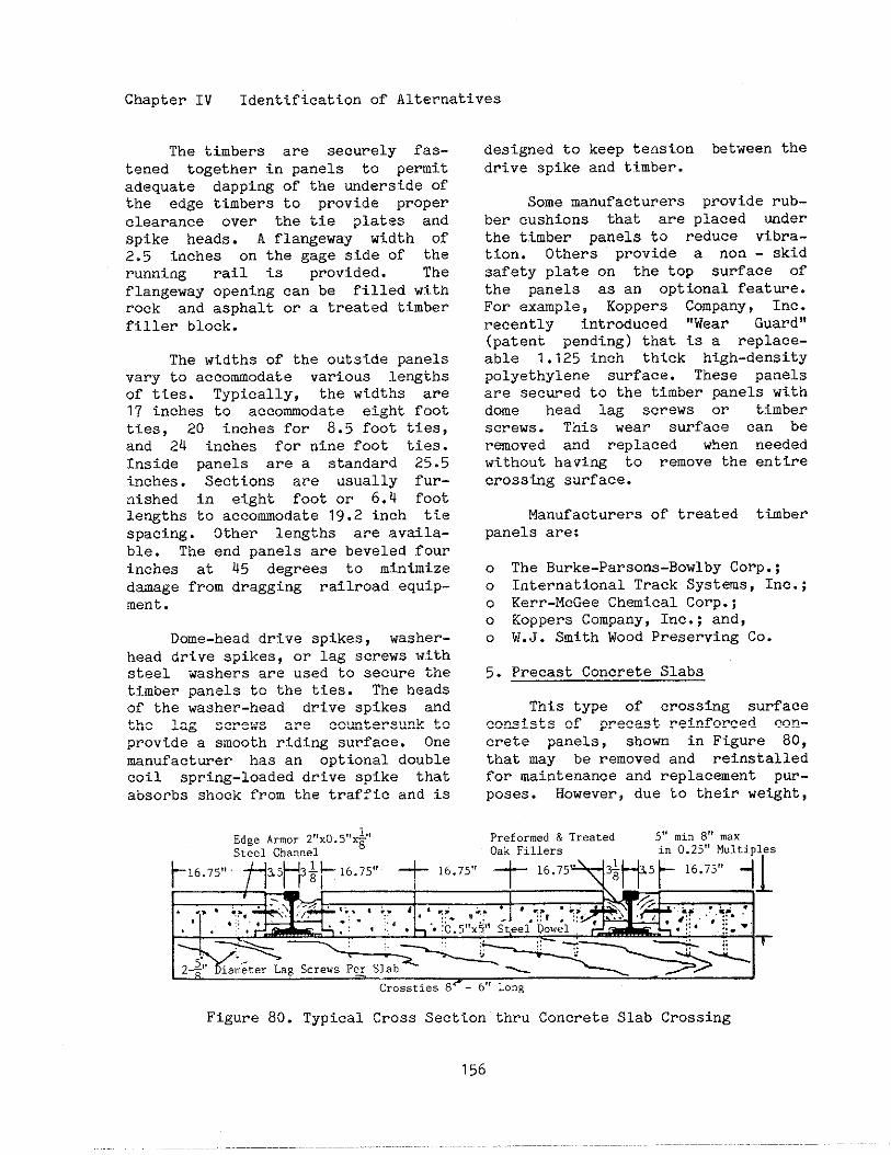
Chapter IV Identification of Alternatives
The timbers are securely fas-tened together in panels to pemitadequate clappingof the ~derside ofthe edge timbers to provide properclearance over the tie plates andspike heads. A flangeway width of2.5 inches on the gage side of therunning rail is provided. Theflangeway opening can be filled withrock and asphalt or a treated timberfiller block.
The widths of the outside panelsvary to accommodate various lengthsof ties. Typically, the widths are17 inches to accommodate eight footties, 20 inches for 8.5 foot ties,and 24 inches for nine foot ties.Inside panels are a standard 25.5inches. Sections are usually fur-nished in eight foot or 6.4 footlengths to accommodate 19.2 inch tiespacing. Other lengths are availa-ble. The end panels are beveled fourinches at 45 degrees to minimizedmage from dragging railroad equip-ment.
Dome-head drive spikes, washer-head drive spikes, or lag screws ~iithsteel washers are used to secure thetimber panels to the ties. The headsof the washer-head drive spikes andthe lag screws are countersunk toprovide a smooth riding surface. Onemanufacturer has an optional doublecoil spring-loaded drive spike thatabsorbs shock from tinetraffic and is
~dge~rmor~,,xo~!!~!!Steel Channel
8
designed to keep tension between thedrive spike and timber.
Some manufacturers provide rub-ber cushions that are placed mderthe timber panels to reduce vibra-tion. Others provide a non - skidsafety plate on the top surface ofthe panels as an optional feat~e.For example, Koppers Company, Inc.recently introduced “Wear Guard”(patent pending) that is a replace-able 1.125 inch thick high-densitypolyethylene surface. These panelsare secwed to the timber panels withdome head lag screws or timberscrews. This wear surface can bermoved and replaced when neededwithout having to remove the entirecrossing surface.
Manufacturers of treated timberpanels are:
o The Burke-Parsons-Bowlby Corp.;o International Track Systas, Inc.;o Kerr-McGee Chemical Corp.;o Koppers Company, Inc.; and,o W.J. Smith Wood Preserving Co.
5. Precast Concrete Slabs
This type of crossing surfaceconsists of precast reinforced cOn-erete panels, shown in Figwe 80,that may be removed and reinstalledfor maintenance and replacement pur-poses. However, due to their weight,
Preformed & Treated 5“ mi. 8“ ma.Oak Fillers in 0.25” M“ltipl,es
t 1675””f115H+b’675°t 1675”t 1675
Z%’ ~iam;ter Lag Screws Per Slab< —1
Crossties 8<- 6,’Long
Figure 80. Typical Cross Section thru Concrete Slab Crossing
156
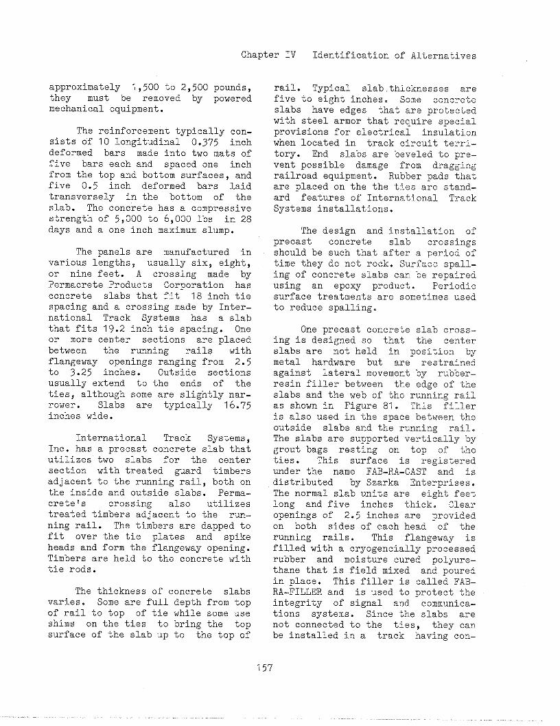
Chapter IV Identification of Alternatives
approximately 1,500 to 2,500 pounds,they must be removed by poweredmechanical equipment.
The reinforcement typically con-sists of 10 longitudinal 0.375 inchdeformed bars made into two mats offive bars each and spaced one inchfrom the top and bottom surfaces, andfive 0.5 inch deformed bars laidtransversely in the bottom of theslab. The concrete has a compressivestrength of 5,000 to 6,000 lbs in 28days and a one inch maximum slump.
The panels are manufactured invarious lengths, usually six, eight,or nine feet. A crossing made byPermacrete Products Corporation hasconcrete slabs that fit 18 inch tiespacing and a crossing made by Inter-national Track Systems has a slabthat fits 19.2 inch tie spacing. Oneor more center sections are placedbetween the rmning rails withflangeway openings ranging from 2.5to 3.25 inches. Outside sectionsusually extend to the ends of theties, although some are slightly nar-rower. Slabs are typically 16.75inches wide.
International Track Systems,Inc. has a precast concrete slab thatutilizes two slabs for the centersection with treated guard timbersadjacent to the rmning rail, both onthe inside and outside slabs. Perma-crete1s crossing also utilizestreated timbers adjacent to the run-ning rail. The timbers are clappedtofit over the tie plates and spikeheads and form the flangeway opening.Timbers are held to the concrete withtie rods.
The thickness of concrete slabsvaries. Some are full depth from topof rail to top of tie while some useshims on the ties to bring the topsurface of the slab up to the top of
rail. Typical slabthicknesses arefive to eight inches. Some concreteslabs have edges that are protectedwith steel armor that require specialprovisions for electrical insulationwhen located in track circuit terri-tory. End slabs are beveled to pre-vent possible damage from draggingrailroad equipment. Rubber pads thatare placed on the the ties are stand-ard features of International TrackSystems installations.
The design and installation ofprecast concrete slab crossingsshould be such that after a period oftime they do not rock. ~~rface spall-ing of concrete slabs can be repairedusing an epoxy product. Periodicsurface treatments are sometimes usedto reduce spalling.
One precast concrete slab crOss-ing is designed so that the centerslabs are not held in position bymetal hardware but are restrainedagainst lateral movement by rubber–resin filler between the edge of theslabs and the web of the running railas shown in Figure 81. This filleris also used in the space between theoutside slabs and the running rail.The slabs are supported vertically bygrout bags resting on top of theties. This surface is registeredunder the name FAB-RA-CAST and isdistributed by Szarka Enterprises.The normal slab units are eight feetlong and five inches thick. Clearopenings of 2.5 inches are providedon both sides of each head of therunning rails. This flangeway isfilled with a cryogencially processedrubber and moisture cured polyure-thane that is field mixed and pouredin place. This filler is called FAB-RA-FILLER and is used to protect theintegrity of signal and communica-tions systems. Since ~ne slabs arenot connected to the ties, they canbe installed in a track having con-
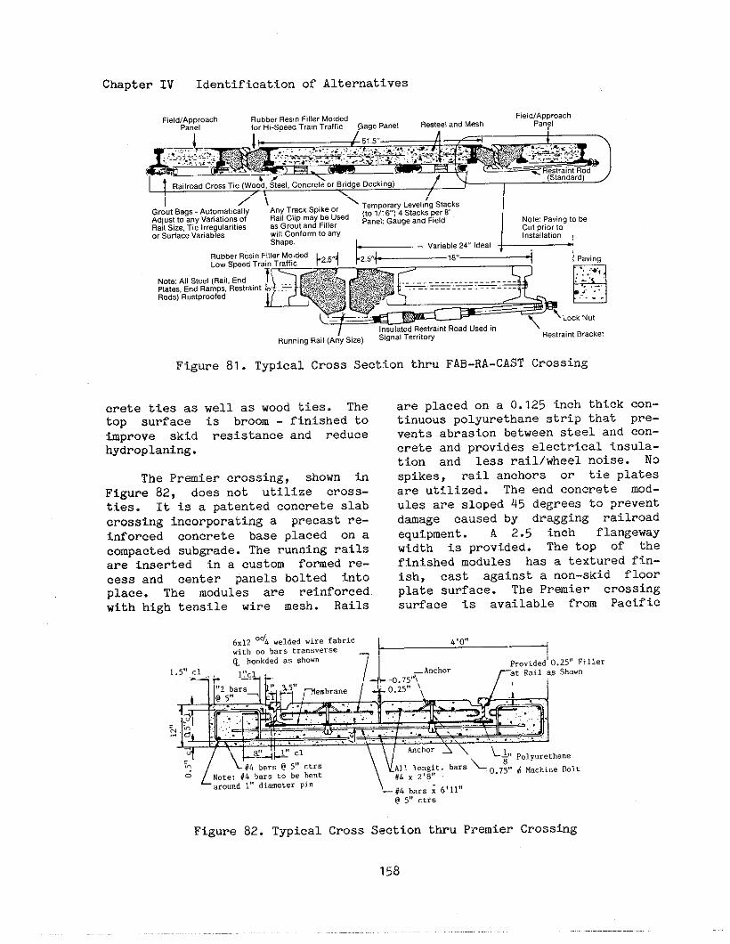
Chapter IV Identification of Alternatives
field;~~yh RubberResinfillerMolded fie!d/APPrOachforHi-SpeedTrainTraffic P8”el
RailroadcrossXe (woo;,S?-1,concreteorBridgeDectingl
GroutBags AutomaticallyAnyTr.ckSpike0,TemporavLevelingSlacks
Adi”sttoanyVariations.+RailCfipmaybeUsed (to1/1614StacksPer6
RailSze,n. IrregularitiesasGroutandfillerPanekGe”geand~eld NotePaving10be
orS.tia.eVariablesCutprior10;~ajyf.rmtoany Installation
NoteAllSteel(Rail,E“d
Rods)R“stproofed
I“s.latedRestraintRoadusedinR.”ningRail(Any5..) %gn.1Territow RestraintBracket
Figwe 81. Typical Cross Section thru FAB-RA-CAST Crossing
crete ties as well as wood ties. Thetop surface is broom - finished toimprove skid resistance and reducehydroplaning.
The Premier crossing, shown inFigure 82, does not utilize cross-ties. It is a patented concrete slabcrossing incorporating a precast re-inforced concrete base placed on acompacted subgrade. The running railsare inserted in a custom formed re-cess and center panels bolted intoplace. The modules are reinforcedwith high tensile wire mesh. Rails
C,lZ‘d~weldedwirefabricwith.. barstre”s”,~.~o hookdedas she”. 7
are placed on a O.125 inch thicktinuous polyurethane strip thatvents abrasion between steel and
cOn-pre-cOn-
crete and provides electrical insula-tion and less rail/wheel noise. Nospikes, rail anchors or tie platesare utilized. The end concrete mod-ules are sloped 45 degrees to preventdamage caused by dragging railroadequipment. A 2.5 inch flangewaywidth is provided. The top of thefinished modules has a textured fin-ish, cast against a non-skid floorplate surface. The Premier crOssingsurface is available from Pacific
~[
L#4 ha,.@ 5,9ctrsNote:#h barsZ. be bentaround1,,diameterPin
Figure 82. Typical Cross Section thru Premier Crosshg
158

Chapter IV Identification of Alteruative~
International Pipe and Engineering,Inc. and Railroad Crossings, Inc.
6. Continuous Concrete pavement
The cross section of a cast-in-place continuous concrete surfacethat covers the entire crossing areaencasing the crossties is shown inFigure 83. This type of surface doesnot allow for track maintenance”with-out removing the surface. Therefore,a continuous concrete pavement shouldbe used only on auxiliary trackswhere track resurfacing till not beneeded duri~ the life of the cross-iw surface. Such a surface might beappropriate at 10catiOns where atrack extends longitudinally in apaved street. While the encasementof a track in a concrete pavement isrelatively expensive, it can provideexcellent riding quality over thetrack area. It is totally unsuitedfor use on a main track.
7. Steel Sections
several manufacturers have pro-duced prefabricated steel sections ofan open grating type, that may beinstalled and removed individuallyfor maintenance and replacement pur-poses. An advantage of this crossingsurface is the better aeration of
the ballast and roadbed sectiOn inthe crosstig area, providing the areawaler the crossing and on top of theballast is kept clear Of dirt anddebris. Accwulation and retention ofdirt on the steel crossing may leadtO rapf.dcorrosiOn. These surfacesgenerally have good riding qualitybut are sometimes difficult to holdin place. Shims are requfred on tOpof the ties. Insulation is requiredin track circuit territory.
Steelplank Corporation producesa Solicl surface sectional steelcrossing that is shown in Figure 84.It is made of die formed 0.25 inchsteel aridconsists of channel shapedplanks for the rmning surface thatare solidly welded to U-shaped sup-porting sections that rest directlyon and are secured to the ties withsix inch lag screws. These sup~rtrisers run perpendicular to the tiesand, while 19.5 inch tie spaci~ ispreferred, minor variations in spac-i~ are not critical. Center sec-tions of the five-plank mits are 6.5feet long and 4.23 feet wide. Ap-proach panels are 20 inches wide.Tapered end sections are available toprevent daage from dragging railroadequtpment. To permit installationand removal of lag screws, accessholes are provided in the center of
8.25” 6 Lo”git”di”alBars 2“d P.”./ ,,.~th 12 lap at midpoint betuee”toD of tze and top of concrete l~langeway
6“ mi”Paving r- (, ,0.25,3”Bevel
,P.vi”g.
,.
8“min
.1 ”.> ,..
,. . ---- .
~ ~ -. ..cb ~5,;b_io“git”di”al Bars
25” min cover l~!fctrs 1219lap15” ctrs
Figure 83. Typical Cross section thru Continuous Concrete Pavement
159
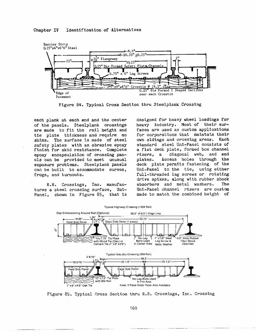
Chapter IV Identification of Alternatives
BarrierStrip
Pavement
Figure 84. Typical Cross Section thru Steelplank Crossing
each plank at each end and the centerof the panels. Steelplank crossingsare made to fit the rail height andtie plate thickness and require noshims. The surface is made of steelsafety plates with an abrasive epoxyfinish for skid resistance. Completeepoxy encapsulation of crossi~ pan-els can be provided to meet unusualexposure problems. Steelplank panelscan be built to accommodate curves,frogs, and turnouts.
R.R. Crossings, Inc. manufac-tures a steel crossing surface, Uni-Panel$ shown in Figure 85, that is
designed for heavy wheel loadi~s forheavy industry. Most of their sur-faces are used as custom applicationsfor corporations that maintain theirown sidings and crossing areas. Eachstandard steel Uni-Panel consists ofa flat deck plate, formed box channelrisers, a diagonal web, and endplates. Access holes through thedeck plate permits fastening of theUni-Panel to the tie, using eitherfull-threaded lag screws or rotatingdrive spikes, along with rubber shockabsorbers and metal washers. TheUni-Panel channel risers are custmmade to match the combined height of
TypicalHighwayCrossing(132#Rail)
G.pDimensioningAro”na8.!1(optional) 56,5(C8.5)Gagetine
.[r~z~g~[’rj
~@~
—e w,thWoodX. (Oak)o’ BoltsUsed L8QScrew& fiberShock
Cemenlme(7X9X86) 1.c..t.,A,..M.t.Iwasher Absorber
TypicalIndustryCrossing(90#Rail]29/16
Eg=pL
—7.9XWV OakXe Note3Rec.GagePanelAl..A..ilable
Figure 85. Typical Cross Section thru R.R. Crossings, Inc. Crossing
160

Chapter IV Identification of Alternatives
the rail and tie-plate. The standardtie spacing is 1~.5 inches, but thesurface can be customized for anycrossing. Flangeways of 2.875 inchesare provided. The steel surfaces arecoated with a coal tar epoxy and thetop surface given a non-skid treat-ment, End sections are tapered toprevent daage from dragging railroadequipment. A 0.25 inch rubber gtrlpcan be fastened between the centerpanels to provide signal insulation.
8. Rubber Panels
This type of cross%ng surfaceconsists of molded rubber panels usu-ally steel-reinforced and with a pat-terned surface. The panels can beremoved and replaced for track main-tenance. There are several manufac-turers of robber crossing panels asdiscussed below.
The Goodyear Tire and RubberCompany makes a rubber crossing sur-face, known as Supercushion and firstproduced in 1954, with panels thatare three feet long, each spanningtwo tie spaces. The center pads ex-tend from rail web to rail web, with2.375 inch flangeway openings. Sidepanels are 21 inches wide at the topand fit against the head of the run-ning rail as shown in Figure 86.
Thus the Goodyear crossing completelycovers an 8 foot 6 inch tie and pro-vides header strips at each end. Fornine foot ties, extension pads arefurnished as a part of the headerstrips. Panels require perfomedwood shims on top of the t%es held inplace by eight inch spikes driventito th~eties. A 0.25 inch rubberabrasion pad is installed on top ofthe shims to reduce abrasion andwear. A dtamond pattern antiskidsurface is molded into the rubber.The transverse jotits between thepanels can be sealed against waterpenetration by applying pressure tocompress a O.125 inch by 0.25 inchprotrusion at the top edge before thepanels are fastened to the ties.Rubber header strips are now providedinstead of wood header boards. Gal-vanized steel end plates are fw-nished to prevent daage by draggingrailroad equipment.
OWI Rubber Products, Inc, asubsidiary of Riedel International,hes recently introduced a rubbercrossing surface called 0~1. Thiscrossing surface, is full-depth andrequlr~s no shims, as shown in Figurea7. It can be installed on concreteties. The panels are custom moldedto fit specific rail and tie platedimensions and the six foot long pan-
RUBBERPLUG15 HEADER1P
SAMEQuANTITIESASPLUGS
Figure a6. Typical Cross Section thru Goodyear Tire & Rubber Co. Crossing
161
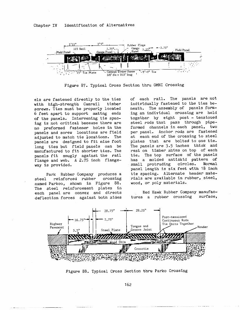
Chapter IV Identification of Alternatives
~?l,?, *,5,,
RubberPlugs
FieldPanel,
.,,.<.-
5/8,,dk x 10.Ylow
Figure 87. Typical Cross Section thru OMNI Crossing
els are fastened directly to the tieswith high-stre%th C=rail timberscrews. Ties must be properly located6 feet apart to support mating endsof the panels. Intervening tie spac-ing is not critical because there areno preformed fastener holes in thepanels and screw locations are fieldadjusted to match tie locations. Thepanels are designed to fit nine footlong ties but field panels can bemanufactured to fit shorter ties. Thepanels fit snugly against the railflange and web. A 2.75 fnch flange-way is provided.
Park Rubber Company produces asteel reinforced rubber crossingnamed Parkco, shown in Figure 88.The steel reinforcement plates fneach panel are convex and directsdeflection forces against both sides
of each rail. The panels are notindividually fastened to the ties be-neath. The assembly of panels form-ing an individual crossing are heldtogether by eight post - tensionedsteel rods that pass through pipe-formed channels in each panel, twoper panel. Anchor rods are fastenedat each end of the crossing to steelplates that are bolted to one tie.The panels are 3.5 tithes thick andrest on timber shims on top of eachtie. The top surface of the panelshas a molded antiskid pattern ofsmall protruding circles. Normalpanel length is six feet with 18 inchtie spacing. Alternate header mate-rials are available in rubber, steel,wood, or poly materials.
Red Hawk Rubber Company manufac-tures a rubber crossing surface,
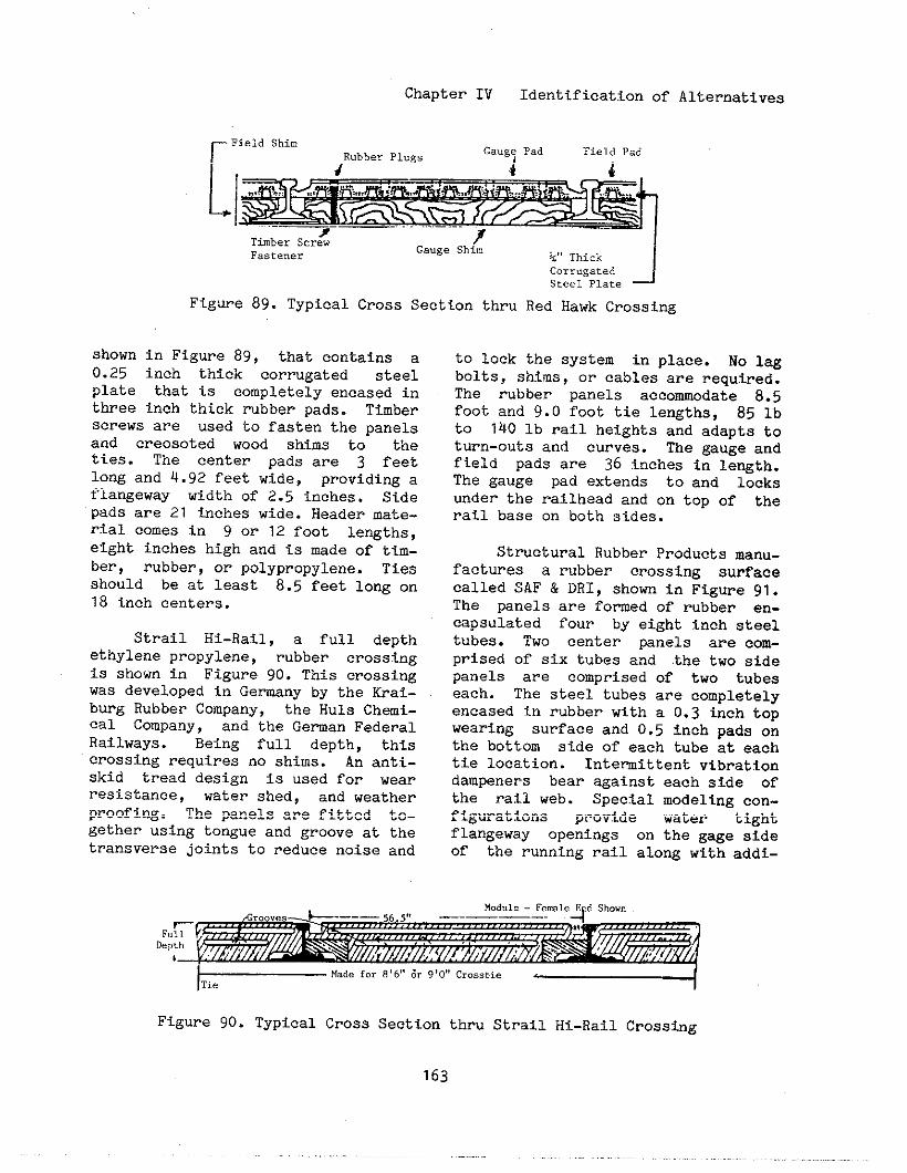
Chapter IV Identification of Alternatives
shown0.25platethree
rField ShimRubber?l”,s Gang,Fad Fieldpad
Corrugatedsteel Plate J
Figure 89. Typical Cross Section thru Red Hawk Crossing
in Figure 89, that contains ainch thick corrugated steelthat is completely encased ininch thick rubber Dads. Timber
screws are used to fasten the panelsand creosoted wood shims to theties. The center pads are 3 feetlong and 4.92 feet wide, providing aflangeway width of 2.5 inches. Sidepads are 21 inches wide. Header mate-rial cOmes in 9 or 12 foot le~ths,eight inches high and is made of tim-ber, rubber, or polypropylene. Tiesshould be at least 8.5 feet long on18 inch centers.
Strail Hi-Rail, a full depthethylene propylene, rubber crossingis shown in Figure 90. This crossingwas developed in Gemany by the Krai-burg Rubber Company, the Huls Chemi-cal Company, and the Geman FederalRailways. Being full depth, thiscrossing requires no shims. An antt-skid tread design is used for wearresistance, water shed, and weatherproofing. The panels are fitted to-gether using tongue and groove at thetransverse joints to reduce noise and
to lock the system in place. No 1-bolts, shims, or cables are requtied.The rubber panels accommodate 8.5foot and 9.0 foot tie lengths, 85 lbto 140 lb rail heights and adapts toturn-outs and curves. The gauge andfield pads are 36 inches in le~th.The gauge pad extends to and 10cksunder the railhead and on top Of therail base on both sides.
Structural Rubber Products manu-factures a rubber crossing surfacecalled SAF & DRI, shown in Figure 91.The panels are fomed of rubber en-capsulated four by eight inch steeltubes. Two center ~nels are com-prised of six tubes and the twO sidepanels are comprised of two tubeseach. The steel tubes are completelyencased in rubber with a 0.3 tich topwearing surface and 0.5 inch pads onthe bottom side of each tube at eachtie location. Intermittent vibrationdampeners bear against each side ofthe rail web. Special modeling con-figurations provtde water tightflangeway openings on the gage sideof the running rail alo~ with addi-
FuDep
Figure 90. Typical Cross Section thru Strail Hi-Rail Crossing
163
,..
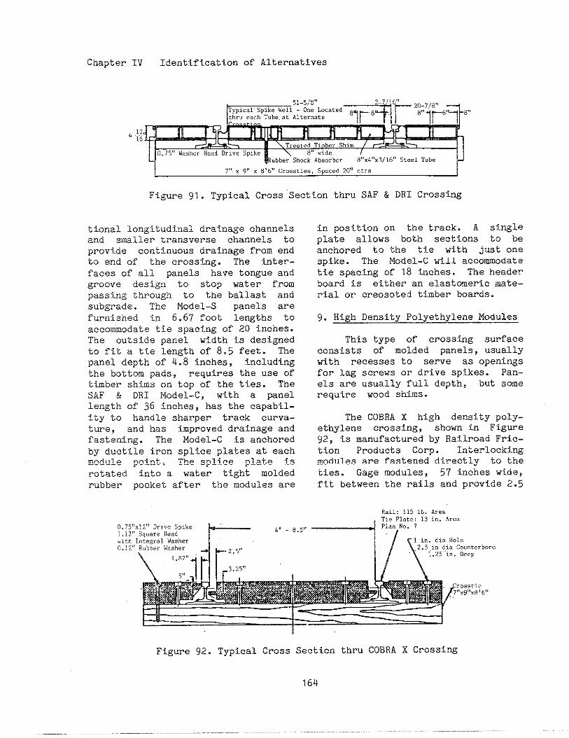
Chapter IV Identification of Alternatives
7“ x 9r’x 8’6”c..s.tles,Sp..ed20”.tr.
Figure 91. Typical Cross Section thru SAF & DRI Crossing
tional longitudinal drainage channelsand smiler transverse channels toprovide continuous drainage from endLo end of the crossing. The inter-faces of all panels have tongue andgroove design to stop water frompassing through to the ballast andsubgrade. The Model-S panels arefu?~ished in 6.67 foot lengths toaccomodaie tie spacing of 20 inches.The outside panel width is designedto fit a tie length of 8.5 feet. Thepanel depth of 4.8 inches, includingthe bottom pads, requires the use oftimber shims on top of the ties. TheSAF & DRI Model-C, with a panellength of 36 inches, has the capabil-ity to handle sharper track curva-ture, and has improved drainage andfastening. The Model-C is anchoredby ductile iron splice plates at eachmodule point. The splice plate isrotated into a water tight moldedrubber pocket after the roodulesare
in position on the track. A singleplate allows both sections to beanchored to the tie with just onespike. The Model-C will accommodatetie spacing of 18 inches. The headerboard is either an elastomeric mate-rial or creosoted timber boards.
9. High Density Polyethylene Modules—
This type of crossing surfaceconsists of molded panels, usuallywith recesses to serve as openingsfor lag screws or drive spikes. Pan-els are usually full depth, but somerequire wood shims.
The COBRA X high density poly-ethylene crossing, shown in Figure92, is manufactured by Railroad Fric-tion Products Corp. Interlockingmodules are fastened directly to theties. Gage modules, 57 inches wide,fit between the rails and provide 2.5
1,..“iLh0.12
1~-— J1
Figure 92. Typical Cross Section thru COBRA X Crossing
164
Chapter
inch flangeways. Field modules, are20 inches wide, extending to the endof an 8.5 foot tie. These modulesspan one tie space of 18 inches.Prefomed and countersunk holes,aligned with the ties, provide adrilling template for the anchoringdrive spikes. The modules are avail-able in various heights between sixand eight inches to accommodate avariety of rail sizes and tie platethicknesses. The mdules are fulldepth and do not require shims.
No national guidelines exist forselecting the appropriate surface fora specified crossing. Thirty-sevenStates have guidelines for selecti~the type of crossing surface. TenStates require the railroad to se-lect, construct, and maintain cross-ing surfaces. Factors that should beconsidered in selecting an appropri-ate surface are as follows.
0
0
0
0
0
Highway traffic - The volme,type, and speed of highway trafficaffects the loadings the surfacemUSt bear. Many States considerAADT and percent trucks whenselecting a surface.
Highway functional classifica-tion - This factor is generally ameasure of the volme and capacityof the highway.
Special vehicles - Crossings usedregularly by special vehiclesshould be given very careful con-sideration.
Railroad traffic - The volume,type, and speed of railroad traf-fic affects the loading the sup-porting track and subgrade bas tobear. Some States consider grosstonnage over the crossing.
Track classification - This factorgenerally is a measure of the
0
0
0
0
as
IV Identification of Alternatives
weight of rail and size as well asthe volume and type of train traf-fic.
Accident histo~ - Particularly,accidents related to the conditionof tl~esurface.
Engineering jud~ent
Costs - Initial construction cost,replacement cost, and maintenanceCost.
Expected service life of surface
At least 23 States consider AADTone factor in selecti~ a crossing
surface. The AADT grou~s vary con-siderably. Rubber crossings arespecifted for crosstigs with AADTtsgreater than a certain value: theminimum value ranges from 1,000 to10,000. Asphalt and timber crossingsare specified for crossings withAADT’s of certain values less than avalue which ranges from 100 to 7,500.
Consideration should be given tousing header boards or header stripsmade of materials other than wood,e.g. rubber, polymeric, or metal.Some States have found that woodenheader boards deterioratee quickly.Whatever is used, careful stepsshould be taken to ensure a cleanseparation between crossing surfaceand approach pavement.
The Florida Department of Trans-portation (DOT), Office of Value En-gineeri~, completed a Highway Plan-ning Research study to develop crite-ria for the selection of crossingsurfaces. The expected life of eachsurface type is reduced by factorsfor various characteristics of acrossing: AADT, percent trucks,track spacing, and gross train tOn-nage. These factors were deteminedfrom data on the actual condition of

Chapter IV Identification of Alternatives
various surface types of variOusages. The equivalent annual cost foreach surface type is then determinedbased on costs per linear foot. Thesurface type with the lowest equiva-lent annual cost is selected.
The Florida DOT has also devel-oped a procedure for the selection ofcrossing surfaces for improvement.Crossings are assigned points in fourareas as follows.
0 Condition of surface - crackingand patching
o Slowing and swerving by drivers
o Dipping and bouncing of vehicles
o Rail and pad movement
The final formula also considers AADTand percent trucks.
The condition of the crossingsurface should be evaluated at leastby physical inspection and by ridingover it. TWO States utilize the MaysRide Meter to assess surface cOndi-tion. One State performs skid tests.A few States assign a rating tO thesurface condition using a question-naire or point system.
Other States have conductedevaluations of crossing surfaces inservice. Because Of the varietY Oftest conditions, procedures, and doc-umentations, the results of theseevaluations are not reported here.Following is a list of States knomto have completed a formal documentedevaluation.
Connecticut Mississippi OhioFlorida Missouri PennsylvaniaIllinois Montana South DakotaLouisiana Nebraska TennesseeMichigan Nevada Wisconsin
F. Removal of Grade Separation Struc-tures
There are nearly 38,000 publicgrade separated railroad - highwaycrossings in the United States. Morethan half of the grade separatedcrossings have a bridge or highwaystructure over the railroad tracks.AS these structures age, become dam-aged, or are no longer needed becauseof changes in highway or railroadalignment or use, alternative engi-neering decisions must be made. Thealternatives to be considered are: 1)upgrade the existing structure to newconstruction standards; 2) replacethe existing structure; 3) remove thestructure, leaving an at-grade cross-ing, and 4) close the crossing andremove the structure.
In general, crossing programsare based upon criteria establishedfor the installation of traffic cOn-trol devices or the elimination of acrossing. However, rehabilitation ofstructures is a significant part ofthe crossing improvement program atboth the State and national level.Currently, there are no nationallyrecognized guidelines for evaluatingthe alternatives available for theimprovement or the replacement Ofgrade separation structures.
Some States have developed eval-uation methods for the selectiOn Ofprojects to remove grade separationstructures. The following is a sum-mary of the State of Pennsylvaniaguidance.
The purpose of the Pennsylvaniaguidance is to assist highway depart-ment personnel in the selectiOn Ofcandidate bridge removal projectswhere the railroad line is abandoned.Both bridges carrying highways overrailroad and bridges carrying aban-
166
Chapter IV Identification of Alternatives
clonedrailroads over highways can beconsidered.
The factors to be considered inselecting candidate projects are asfollows.
For bridges carrying highway over anabandoned railroad
o Bridges that are closed or postedfor a weight limit because Ofstructural deficiencies (Thelength of the necessary detour isimportant.)
o Bridges that are narrow and there-fore hazardous
o Bridges with hazardous verticaland/or horizontal alignment of thehighway approaches (Accident re-cords can be reviewed to verifysuch conditions.)
For bridges carrying abandoned rail-road over a highway
o Bridges that are structurally ~n-soud and a hazard to trafficoperating mder the bridge
o Bridges whose piers and/or abut-ments are in close proximity tOthe traveled highway and consti-tute a hazard
o Bridges whose vertical Clearanceover the highway is substandard
o Bridges where the vertical and/orhorizontal alignment of the high-way approaches are hazardous pri-marily because of the location ofthe bridge
It should be noted that thisguidance is applicable to situationsthat involve abandoned rail lines.
In those instances where a railroad
cOntin~~estO Operate, other decisionsmust be made. Some considerationsfor removing a grade separation over,or ~der a rail line that is stillbeing operated are as follows.
0 Can the structure be removed andreplaced with an at-grade cross-ing?
o ~o is liable if an acc,ident oc-curs at the new at-grade crossing?
o If the structure is to be rebuilt,who is to pay the cost or who isto share in the cost and to whatextent?
o To what standards is the structureto be rebuilt?
0 mat is the future track use andpotential for increase in trainfrequency?
o If tilestructure is replaced withan at-grade crossing, what delaysto motorists and emergency servicewill result? Are alternate routesavailable?
0 mat impact will an at-gradecrossing have on railroad Opera-tions?
o mat will be the impact on safetyof an at-grade crossing vs. astructure?
To ensure a proper answer tothese and other related questions, anengineering evaluation, includingrelative costs, should be conducted.This evaluation should follow proce-dures described in Chapter V.
Chapter IV Identification of Alternatives
G. References
1. American National Standard Prac-tices for Roadway Lighting, New York,NY: Illuminating Engine~ing Societyof America, July 1977.
2. Code of Federal Regulations, Title23, Washington, DC: Generai Services~tiinistration, published annually.
3. Collision of Amtrak Train No. 88with Tractor Lowboy~ailer Com-—.zbination Truck, Rowland, N.C., August25, lg83,~shington, ~–—”— NationalTransportation Safety Board, ReportNo. NTSB/RHR-84/01, 1984.
ties Comission, June 1974.
5. Federal-Aid Highway Program Man-ual, Washington, DC: Feder_~w~~ini~tration, updated periodically.
6. Federal Highway AtiinistrationSurvey of Region and Division Of-fices, unpublished, 1984.
7. Federal Railroad Atiinistration,Data from the U.S. DOT/AAR NationalRail-Highway CrOsaing Inventory,1g84.
8. Field and Office Manual fOr prO=file Surveys of Highway-Rail At-Grade—Crossings on Existing Paved Roadways,~1~, FL: Florida Departmentof Transportation, September 1984.
9. Fitzpatrick, Gary M., Standardiz-ation of Criteria for R~w~————=-g Construction, Talla-hassee, FL: Florida Department ofTransportation, Office of Value Engi-neering, August 1982.
10. Guide for Selecting, Locating,and ~~~ning Traff~B%r=a~_-= ——— __‘-— Anerxcan Asaoc!ation ofington, DC:State Highways and Transportatf.onOfficials, IY77.
11. Heathington, K.W. and T. Urbanik,~,Driver Information Systems fOr High-way-Railway Grade Crossings”, HighwayResearch Record No. 41~, Wash~ngton,
_ -—
DC: H~ghw~y Research Board, 1972.
12. HedleY, Willim J., Proceedings,_-—_—
American Railway Engineering Associa-“-~~-e~~~;ago, IL:
——tion 1952.—-—~
13. Hedley, Wtlliam J., Railroad-Highway Grade Crossing Surfaces,Washington, DC: Federal Highway~-ministration, August 1979.
14. Illinois Comerce Comission Gen-—— —-——138 Revisederal Order No. , Spring-
field, IL: Illinois COmerce COmis-sion, 1Y73.
15. Knoblauch, Karl, Wayne Hucke, andWillis Berg, Rail Highway Crossing.——Accident Causation Study. VOlme II,_—_, __ ——_— _Technical Report, Washington, DC:ma~=a7—Adminlstrat ton, Re-port FHWA/RD-81/083, August 1982.
16. Manual for Railway Engin~ering,Wasl~ington,DC: American Railway En-gineering Associatf.on,1981.
17. Manual on Uniform Traffic Control—-—Devices,‘———Washington, DC: Feder~———Highway Atiiniatration, 1g78, revisedlg7g, 1983, 1984.
18. Mather, Richard A., “Public Rail-road-Highway Grade Crossing Illumin-ationProject in Oregon”, Washington,DC: Transportation Research Board,January 1983.
19. Monroe, Richard L., Debra K.Munsel1, and T. Jaes Rudd, ConstantWarning Time Concept Development for————
Chapter IV Identification of Alternatives
Motorist Warning at Grade Crossings,Washington, DC: Federal Railroad Ad-ministration, Report FRA/ORD-81/07,May 1981.
20. Morrissey, J., The Effectivenessof Flashing Light~nd FlashingLights with Gates in Reducing Agc~dent Frequency at Public Rail-HighwayCrossings, 1975-1g78, Washington, DC:Federal Railroad Administration andFederal Highway Administration, Aprillg80.
21. A Policy on Geometric Design of.———=Y>d Streetsv Washingtonv DC:American Association of State Righwayand Transportation Officials, 1984.
22. Proceedings, National Conferenceon RXo=hway Crossing Safet~Colorad~a~ U.S. Air ForceAcademy I~ter-~’ Education Center,A~ust 1974.
23. Proceedings, National Conferenceon Railroad-Highway Crossing Safety,———Salt Lake City, UT: University%fUtah, August 1g77.
24. Proceedings, National Rail-High-——way Crossing Safety Conference, Knox-ville, TN: The University of Tennes-see, June 1980.
25. Rail-Highway Grade Crossing Warn-——ing ~ems and Surfaces, Alexandria,r— The Railway Progress Institute,lg83.
26. Roadway Lighting Handbook, Wash-ington, DC: Federal Highway A&ninis-tration, Implementation Package 78-15, December 1978.
27. Ruden, Robert J., Albert Burg,and John P. McGuire, &tivated Ad-vance Warning for Railroad Grade——Crossings, Washington, DC: Federal—-—Highway Administration, Report FHWA/RD-80/003, July 1982.
169
28. Standard Alphabet for Highway.Signs and Markings, Washington, DC:Federal.Highway Administration.
29. Traffic Control Devices Handbook,Wash~&~:——— Federal Highway Ad-ministration, 1983.
30. Uniform Vehicle Code and ModelTraffic Ordinance, National Committee’——. —of Uniform Traffic Laws and Ordin-ances, Charlottesville, VA: TheMichte Company, 1961 and Supplement,1979.
31. ‘“Use of Traffic Divisional Is-lands at Railroad Grade Crossings,”Technical Notes 84-1, Albany, NY: New~e=e nt of Transportation,March 1984.
32. West Virginia’s Highway-RailroadManual, Charleston, WV: West Virgi~ia Department of Highways, RailroadSection, Right of Way Division, pre-liminary, 1984.
V. SELECTION OF ALTERNATIVES
In this Chapter, analyses arepresented to assist in tiprovementalternative selectiOn by exainingthe costs and benefits of each alter-native and by making comparisonsamong alternatives. In addition,these analyses can be used to prior-itize prOjects for implementationsand funding.
Methods for selecttng alterna-tives and economic analysis tech-niques which may be utilized are dis-cussed. In addition, the Rail-High-way Crossing Resource Allocation Pro-cedure is presented. Other low-cOstsolutions are also discussed.
A. Wsrraot Prmedures
As noted in Chapter IV, someFederal and/or State guidelines havebeen established for certain types ofimprovements. In some cases, theseguidelines serve as a threshold forimplementation actton when certainconditions exist, thus dictating theatiprOpriate hprovement alternative.In most cases, however, the guide-lines provide for several alternativeimprovements.
B. Economic Aoalysis Pr@edwes
An economic analysis my bePerformed to detemine the possiblealternative improvements which couldbe made at a railroad-highway gradecrossing. These procedures involveestimates of expected project costsand safety and operational benefitsfor each alternative. Much Of thefOllOwing discussion is adapted fromthe methodology presented in theHighway safety Improvement ProgrmUser’s Manual (HSIP User,s Manual).
Imltially, information on thefollowing elements must be estab-lished, using the best availablefacts and estimates.
o Accident costso Interest rates0 Service lifeo Initial improvement co~t~o Maintenance costso Salve~gevalueo Traffic growth rates
Other considerations are theeffestiveness of the Improvement Lnreducing accidents and the effects ontravel, such as reduction in delays.
The Cost information is notalways readily available, thus someStates are reluctant tO impute adollar cost to human life or personalinjury. Considerable care must beused in establishing values for thesecosts.
The selection of accident costvalues is of major importance in theeconomic analyses. The two mostcommon sources of accident costs are:
o National Safety Council (NSC), and
o National Highway Traffic SafetyAtitnistration (NHTSA).
NSC costs include wage losses,medical expenses, insmance adminis-trative costs, and property damage.NHTSA i]~cludesthe calculable costsassociated with each fatality andinjury plus the cost to society, i.e.consumption losses of individuals andsociety at large caused by losses inproduction and the inability to pro-duce. Many states have developedtheir own values which reflect theirSituation and philosophy. Whichever
Chapter V Selection of Alternatives
is selected the values ought to beconsistent with those used for othersafety improvement programs.
An appropriate interest rate isneeded for most of the proceduresconsidered. The selection of aninappropriatee interest rate couldresult in unsuitable project costsand benefits and thus, in selectionof an ineffective solution. Periodsof rapid inflation and fluctuation ofinterest rates make the identifica-tion of an appropriate rate somewhat
difficult. The standard rates usedby the highway department should beselected.
The HSIP Users’ Manual statesthat the service life of an improve-ment should be equal to the timeperiod that the improvement can rea-sonably affect accident rates. Bothcosts and benefits should be calcu-lated for this time period. Hence,the service life is not necessarilythe physical life of the improvement,For railroad-highway grade crossings,however, it is a reasonable assmp-tion that the improvement would beequally effective over its entirephysical life. Thus, selecting theservice life equal to the physicallife would be appropriate.
The selected service life canhave a profound effect on the eco-nomic evaluation of improvement al-ternatives; therefore, it should beselected using the best availableinformation. The Depreciation Branchof the Interstate Comerce Comission(ICC) periodically studies individualClass I railroads to detamine theeconomic life of railroad signalequipment. For example, their re-sults indicate that the average ICCsignal equipment depreciation periodin 1977 for the 20 largest Class Irailroads was 30 years.
Project costs should includeinitial capital costs and maintenancecosts and be considered as lffe-cyclecosts, i.e. all costs are distributedover the service life of the improve-ment.
The installation cost elementsInclude the following.
00000
Preliminary engineeringLaborMaterialLease or rental of equipmentMiscellaneous costs
The maintenance costs are allthose costs associated with keepingthe system and components in Opera-ting condition. Maintenance costsare discussed in Chapter VII.
The salvage value is def;.nedasthe dollar value of a project at theend of its service life and is there-fore dependent on the service life ofthe project. For crossing signalimprovement projects, salvage valuesare generally very smal.1.
Tnere are several accepted eco-nmic analysis methods, all of whichrequire differant inputs, assump-tions, calculations, and methods, andwhich may yield different results.Several appropriate methods are de-scribed here.
1. Cost-EffectivenessAnalysis
The cost-effectiveness analysismethod is an adaptation of a tradi-tional safety analysis procedurebased on the calculation of the costto achieve a given unit of effect(reduction in accidents). The signif-icant aspects of this procedure isthat it need not require the assign-ment of a dollar value to hmaninjuries or fatalities, and requiresminiml manpower to apply.
172
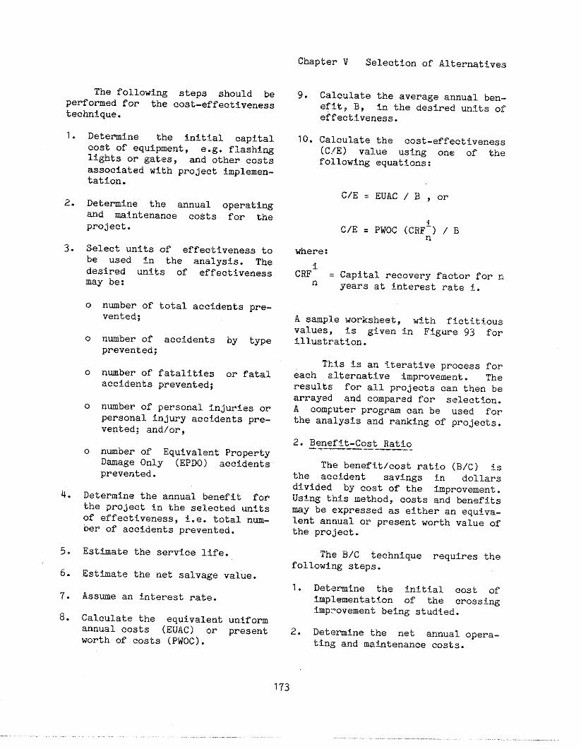
Chapter V Selection of Alternatives
The following steps should bePerformed for the cost-effectivenesstechnique.
1.
2.
3.
4.
5.
6.
7.
8.
Detemine the initial capitalcost of equipment, e.g. flashi~lights or gates, and other co~t~associated with project implemen-tation.
Determine the annual operatingand maintenance COStS for theproject.
Select units of effectiveness tobe used fn the analvsis. Thedesired units of eff~ctivenessmay be:
0 nmber of total accidenta pre-vented;
0 n~ber of accidents by typeprevented;
0 nmber of fatalities or fatalaccidents prevented;
0 n~ber of personal injuries orpersonal injury accidents pre-vented; and/or,
0 nmber of Equivalent PropertyD~age only (EPDO) accidentsprevented.
Determine the annual benefit fortha project in the selected unitsOf effectiveness, i.e. total nm-ber of accidents prevented.
Esttiate the service life.
Esttiate the net salvage value.
Assme an interest rate.
Calculate the equivalent unifomannual cOsts (EUAC) or presentworth of costs (PWOC).
9.
10.
Calculate the average annual ben.-efitj B, in the desired units ofeffactiveness.
Calculate the cost-effectiveness(CfE) value using one of th<?following equations:
C/E = EUAC / B , or
C/E = PWOC (CRF1) / Bn
where:
CRFi = Capital recovery factor for Cln years at interest rate i,
A smple worksheet, with fictitj-o”svalues, is given tn Figure 93 forillustration.
This is an iterative process foreach alternative improvement. Theresults for all projects can then bearrayed and compared for selectton.A computer progra can be used fOrthe analysis and ranking of projects.
2. Benefit-Cost Ratio-— ——_——___
The benefit/cost ratio (B/C) isthe accident savings in dollarsdfvided by cost of the improvement.Using thts method$ costs and benefits
~Y be expressed as either an equiva-lent annual or present worth value ofthe project.
The B/C technique requires thefollowing steps.
1. Detemine the initial cost Ofimplementation of the CrossingImpl-ovementbefng studfed.
2. Detemine the net annual opera-tfng and matitenance costs.
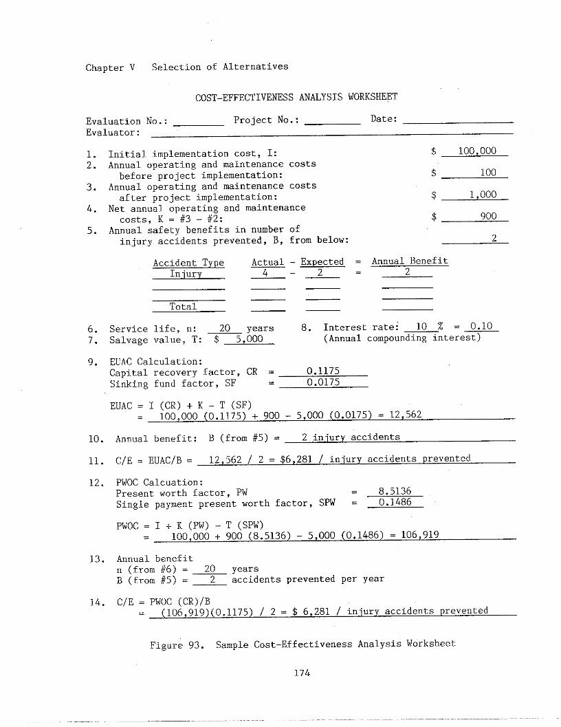
Chapter V Selection of Alternatives
COST-EFFECTIVENESSANALYSIS WORKSHEET
Evaluation No.: Project No.: Date:Evaluator:
1. Initial implementation cost, I: $2.
100,000
Annual operating and maintenance costsbefore project implementation: $ 100
3. Annual operating and maintenance costsafter project implementation: $ 1,000
4. Net annual operating and maintenancecosts, K = #3 - #2: $ 900
5. Annual safety benefits in number ofinjury accidents prevented, B, from below: 2
Accident Type Actual - Expected = Annual BenefitInlury 4 2= 2— -—
— —— —
Total — —
6. Service life, n: 20 years 8. Interest rate: 10 % = 0.107. Salvage value, T: $ 5,000 (Annual compounding interest)
9. EUAC Calculation:Capital recovery factor, CR = 0.1175Sinking fund factor, SF = 0.0175
EUAC = I (CR) + K - T (SF)100,000 (0.1175) + 900 - 5,000 (0.0175) = 12,562
10. Annual benefit: B (from #5) = 2 iniury accidents
11. C/E = EUAC/B = 12,562 / 2 = $6,281 / iniury accidents prevented
12. PWOC CalcuatiOn:Present worth factor, PW 8.5136Single payment present worth factor, SPW = 0.1486
PWOC = I + K (PW) - T (SPW)100,000 + 900 (8.5136) - 5,000 (0.1486) = 106,919
13. Annual benefitn (from #6) = 20 yearsB (from #5) = Z accidents prevented per year
14. C/E = PWOC (CR)/B(106,919)(0.1175)/ 2 = $ 6,281 / injury accidents prevented
Figure 93. Sample Cost-EffectivenessAnalysis Worksheet
174
3. Determine the annual safetj~bene-fits derived from the project.
4. Assign a dollar value to eachsafetY benefit unit (NSC, NHTSAor other).
5. Esttiate the gervice life of theproject baged on patterng ofhistoric depreciation of stiilartype9 of projects.
6. Estimate the salvage value of theproject or improvement titer itsprimary service life has ended.
7. Determine the ~nterest rate bytaking into account the timevalue of money.
8. Calculate the B/C ratio u9tngequivalent unifOrm annual ~Ogts(EuAc) and equivalent uniformannual benefits (EUAB).
9. Calculate the B/C ratio usingpresent worth of cost9 (PWOC) andpresent worth of benefItg (PWOB).
A 9ample worksheet with ficti-tious value9 for the B/C analysis isgiven in Figure g4.
This method requires an esttiateof accident severity in dollar termg,which can greatly affect the outcome.It is relatively easy to apply and isgenerally accepted in engineering andfinancial studies. As with the cost-effectiveness method, the process canbe performed for alternative improve-ments at a single crossing, and ar-rayed for all projects to deteminepriorities for funding.
3. Net Annual Benefit
The net annual benefit method i9based on the premise that the rela-tive merit of an tiprovement is meas-ured by ita net annual benefit. This
Chapter V Selection of Alternatives
method is used to select improvementsthat will engure maximum total bene-
fits at each location. The net an-nual benefit of an improvement isdefined as follows.
Net Annual Benefit ❑ (EUAB) - (EUAC)
where:
EU&B = Equivalent UnifOm AnnualBenefit
EUAC = Equivalent Uniform Annualcost
A positive value for net annualbenefit indicates a feasible improve-ment and the improvement, or set ofimprove~~ents, with the largest p09i-tive net annual benefit i9 consideredto be the best alternative.
The following steps should beused to compute the net annual bene-fit.
1. Estimate the initial cost, annualcOst, te~inal value, and servicelife of each improvement.
2. Esttmate the benefits (in dol-lars) for each improvement.
3. Select an !nterest rate.
4. Compute the EUAB.
5. Compute the EUAC.
6. Calculate the Net Annual Benefitof each improvement.
For the data and calculationsshown in Figwe 94, the net annualbenefit would be $g1,438, dete~inedfrom an EUAB of $104,000 less an EUACof $12,562.
While any of the three methodsis an acceptable procedure to followfor economic analyses, they might
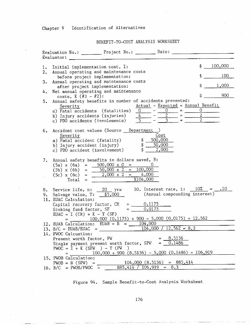
Chapter V Identification of Alternatives
BENEFIT-TO-COST ANALYSIS WORKSHEET
Evaluation No.: Project No.: Date:
Evaluator:
1.2.
3.
4.
5.
6.
7.
8.9.11.
12.13.14.
15.
16.
Initial implementation coat, I: $ 100,000
Annual operating and maintenance costsbefore project implementation: $ 100
Annual operating and maintenance costsafter project implementation: $ 1,000
Net annual operating and maintenancecosts, K (#3 - #2): $ 900
Annual safety benefits in number of accidents prevented:Severity Actual - Expected = Annual Benefit
a) Fatal accidents (fatalities) ~ - ~ = o
b) Injury accidents (injuries) 2c) PDO accidents (involvements) 5 - 3 = 2
Accident cost valuea (Source Department )Severitv ~
a) Fatal accident (fatality) $ 500,000b) Injury accident (injury) $ 50,000c) PDO accident (involvement) $ 2,000
Annual safety benefits in dollars saved, B:(5a) x (6a) = 500,000 x o = o
(5b) X (6b) = 50,000 x 2 = 100,000
(5c) X (6c) = 2,000 x 2 = 4,000Total = $104,000
Service life, n: 20 yrs 10. Interest rate, i: 10Z = 10
Salvage value, T: $5,000 (Annual compounding intereat)-EUAC Calculation:Capital recovery factor, CR = 0.1175Sinking fund factor, SF - 0.0175EUAC = I (CR) + K - T (SF) -
100,000 (0.1175) + 900 - 5,000 (0.0175) = 12,562EUAB Calculation: EUAB = B = 104,000B/C = EUAB/EUAC = 104,000 / 12,562 = 8.3PWOC CalcuatiOn:Present worth factor, PW 8.5136Single payment present worth factor, SPW = 0.1486PWOC=I+K(SPW )- T(PW )
100,000 + 900 (8.5136) - 5,000 (0.1486) = 106,919PWOB Calculation:PWOB = B (SPW) = 104,000 (8.5136) = 885,414B/C = PWOB/PWOC = 885,414 I 106,919 = 8.3
Figure 94. Sample Benefit–to-Cost Analysis Worksheet
176
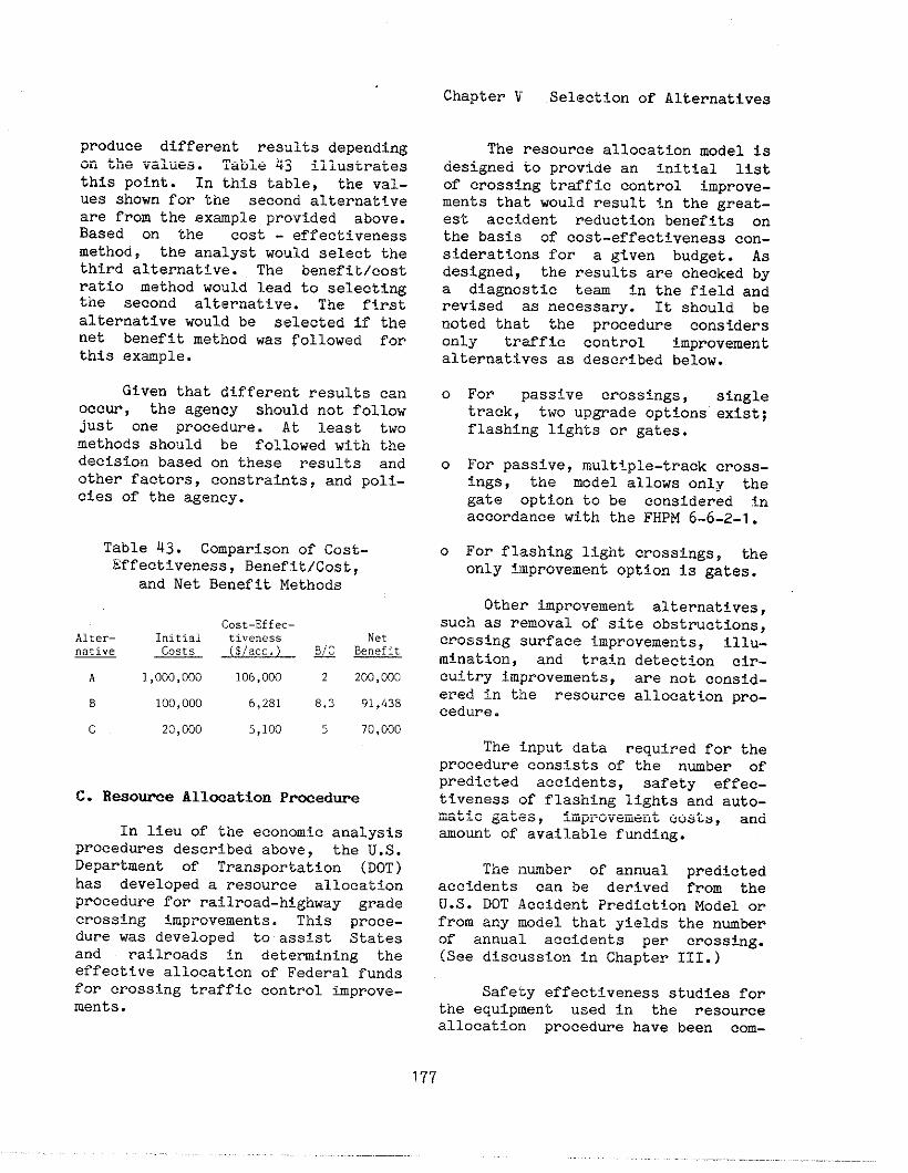
produce different results dewendins.-on the values. Table 43 !Ilustratesthis point. In this table, the VSI-ues shown for the second alternat+.veare from the example provided above.Based on the cost - effectivenessmethod, the analyst wol~ldselect thethird alternative. The benefit/costratio method would lead to selecti~the second alternative. The firstalternative would be selected if thenet benefit method was followed forthis example.
Given that different results canOccur, the agency should not followjust one procedure. At least twomethods should be followed with thedecision based on these results andother factora, constraints, and Poli-cies of the agency.
Table 43. Comparison of COst-Effactiveness, Benefit/Cost,
and Net Benefit Methods
Cost-Effec–A1ter– I“itial ti.eness Net
m ~ (5/ace.) ~ ~
A 1,000,000 106,000 2 200,000
B 100,000 6,281 8.3 91,&38
(
c.
20,000 5,100 5 70,000
Resouroe All@ation Prwedwe
In lieu of the economic analysisprocedures described above, the U.S.
Department Of Transportation (DOT)has developed a resource allocationprocedure for railroad-highway gradecrossing improvements. This proce-dure was developed to asstst Statesand railroads in determining theeffectfve allocation of Federal fundsfor crossing traffic control improve-ments.
Chapter V Selection of Alternatives
The resource allocation model isdesigned to provide an initial listof crossing trsffic control improve-ments that would result in the great-est accSdent reduction benefits onthe basis of cost-effectiveness con-siderations for a given budget. Asdesigned, the results are checked bya dia~ostic tea fn the field andrevised as necessary. It should benoted that the procedure considersonly traffic control improvementalternatives as described below.
o For passive crossings, singletrack, two upgrade options exist;flashing lights or gates.
o For passive, multiple-track cross-ings, the model allows only thegate option to be considered tnaccordance with the FHPM 6-6-2-1.
0 For flashing light crossings, theonly improvement option is gates.
Other improvement alternatives,such as removal of site obstructions,crossing surface improvements, illu-mination, and train detection cir-cuitry improvements, are not consid-ered in tine resource allocation prO-cedure.
The input data required for theprocedure consists of the nmber ofpredicted acctdents, safety effec-tiveness of flashing lights and auto-~tiC gates, improvement costs, andsmount of available funding.
The ]tumber of annual predictedacctdents can be derived from theU.S. DOT Accident PredictIon Model orfrom any model that yields the nuberof annual accidents per crosstig.(See discussion in Chapter III.)
Safe’cyeffectiveness studies forthe eouioment used in the resource.,–.—=allocation procedure have been com-
177
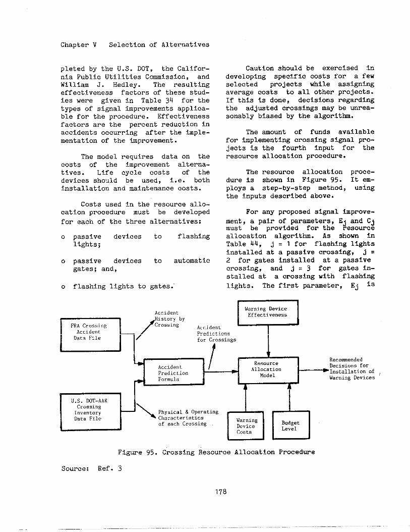
Chapter V Selection of Alternatives
pleted by the U.S. DOT, the Califor-nia public Utilitias Commission, andWilliam J. Hedley. The resultingeffectiveness factors of these stud-ies were given In Table 34 for thetypes of signal improvements applica-ble for the procedure. Effectivenessfactors are the percent reduction inaccidents occurring after the imple-mentation of the improvement.
The model requires data on thecosts of the improvement alterna-tives. Life cycle costs of thedevices sho~ld be used, i.e. bothInstallation and maintenance coats.
Costs used in the resource allo-cation procedure must be developed
for each of the three alternatives:
0 passive devices to flashinglights;
0 passive devices to automaticgates; and,
o flashing lights to gates.”
Caution should be exercised indeveloping specific costs for a fewselected projects while assigningaverage costs to all other projects.If this is done, decisions regardingthe adjwted crossings may be unrea-sonably biased by the algorithm.
The amount of funds availablefor implementing crossing si~al prO-jects is the fourth input for theresource allocation procedure.
The resource allocation proce-dure is shown in Figure 95. It em-ploys a step-by-step method, usingthe Inputs described above.
For any proposed signal improve-ment, a pair of parameters. Ej and Cjmust be provided for the resourceallocation algorithm. As shown inTable Q4, j = 1 for flashing lightsinstalled at a passive crossing, j =2 for gatea installed at a passfvecrossing, and j = 3 for gates in-stalled at a crossing with flashinglights. The first parameter, Ej is
!env
Accident
-/
Hist”ry byFRA Cr”s.inR CrossingAccident
Acc.i.d
Data FilePredi.ctio”sf“. Crossings
+,/ ~ 1
ResourceRecommended
Accident AllocationDecisions for
Prediction Model~Installation of ;
Form”la Warning Devices
k ?1
DU.S. DOT-AARCross.”gI“ve”tory
\Physical & Operating
Data File Characteristics
dd
War”i”gof each Crossing Device
Budget
costsLevel
Figure 95. Crossing Resource Allocation Procedure
Source: Ref. 3
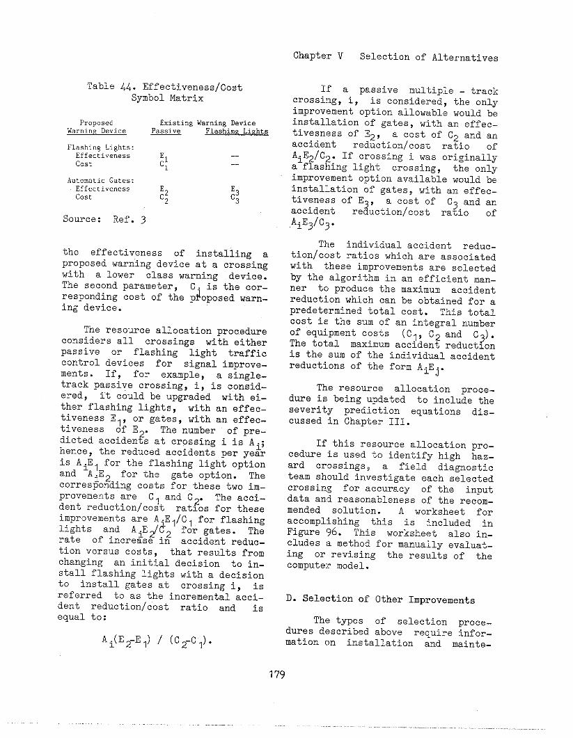
Chapter V Selection of Alternatives
Table 44. Effectiveness/CostSymbol Matrix
Proposed Existing Warni”~ DeviceWarning Device ~ F1.shi”z LiKhts
Flashing Lights:Effectiveness :1
--
Cost -.1
Automatic Gates:Effectivenesscost :2 :3
2 3
Source: Ref. 3
the effectiveness of installing ~proposed warning device at a crossingwith a lower class warning device.The second parameter, C. is the Cor-responding cost of the p~oposed warn-ing device.
The resource allocation procedureconsiders all crossings with eitherpassive or flashing light trafficcontrol devices for signal improve-ments. If, for example, a single-track passive crossing, i, is consid-ered, It could be upgraded with ei-ther flashing lights, with an effec_
tiveness El, or gates, with an effec-tiveness of E . The number Of pre-
2dieted acciden s at crossing i is Ai;hence, the reduced accidents per yearis AiEl for the flashing light optionand AiE2 ,for the gate optiOn. Thecorresponding costs for these two im-provements are Cl and C2. The acci-dent reduction/cost ratios for theseimprovements are A.El/Cl for flashinglights and A.E~d2 for gates. Therate of incre~se in accident reduc-tion versus costs, that results fromchanging an initial decision to in-stall flashing lights with a decisiontO install gates at crossing i, is
referred to as the incremental acci-dent reduction/cost ratio and isequal to:
Ai(E2-E1) / (C2-C1).
If a passive multiple - trackcrossi]tg,i, is considered, the onlyimprovement option allowable would beinstallation of gates, with an effee-.tivesness of E2, a cost of C2 and anaccident reduction/cost ratio ofAiE2/C2. If crossing i was originallya flashing light crossing, the onlyimprovement option available would beinstallation of gates> with an effec-.
~~~K~! ‘f~~~;.t~o~~~~s~fr~?i~d ~AiE3/C3.
The individual accident reduc-tion/cost ratios which are associatedwith these improvements are selectedby the algorithm in an efficient man-ner to produce the maximum accidsntreduction which can be obtained for apredetermined total cost. This totalcost is the sum of an integral numberof equipment costs (Cl, C2 and C3).The total maximum accident reductionis the sum of the individual accidentreductions of the form A.E..
IJ
The resource allocation proce-dure is being updated to include theseverity prediction equations dis-cussed in Chapber III.
If this resource allocation pro-cedure is used to identify high haz-ard crossings~ a field diagnosticteam should investigate each selectedcrossing for accuracy of the inputdata and reasonableness of the recom-mended solution. A worksheet foraccomplishing this is included inFigure 96. This worksheet also in-cludes a method for manually evaluat-ing or revising the results of thecompute:rmodel.
D. Selection of Other Improvements
The types of selection proce-dures described above require infor-mation on installation and mainte-
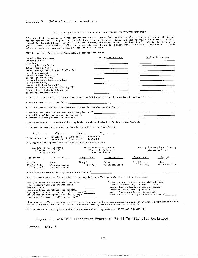
Chapter V Selection of Alternatives
RA1L-HIGHWAYcEOss18GRE50URCEALLKATIONPRmEDUREVERlF1CAT1ONWORKSHEET
This worksheet pr.vld.. , fo...t ..d i..t...si..s f.r US* 1. field .valu.tiOn .f crossi.s tO determine if jnfti.;recome”datio.s for warning device i.stallati.ns f... the Resource Al1“cation P.”ted.re sh”,ild be r~v;seal. SLep.thr.”gh 5, described below, .h.”ldbe followed i“ .aking the deter.i.ation. 1“ Steps 1 and 3, the in,txal i“for..tie.
(left ..1”.”) is obtained f... office inventorydata prior to the field i.specti.”. 1“ Step 4, the decision criteria
..1..s are “btai”ed fro. the Resource AllocationM“delpri.tot,t.
STEP1: ValidateDataused i“ Calc”lati.gPredictedAccident.:
Cr.s.in8 Ch.r.cterlstic Initial I“for.ation Revised l“for.atio”
Crossing Nu.berLocatl.”Existi”swarningDeviceTotalTrainsperDayA.”ual Average Daily Highw.y Traffic (.)Day thr” Trains (d)Numb,.ofMainTracks (t)1. Highway Paved? (hp)Maxi.”. Ti.etable Speed, .ph (.s)IlighwayType (ht)N“.ber of Hi8h”ay Lanes (hi)N“.ber of Yea., of Accident History (T)Nu.ber of Accidents i“ T Years (N)Predicted Accide.t Rate (A)
STEP 2: Cal.”late Revised Ac.ide”t Prediction fr.. ~ Formula if *.Y Data i“ Step 1 has been Revised.
Re”ised Predicted Accidents (A) =
STEP 3: Validate Cost a“d Effective”essData for Rec.me.ded Warning Device
A.s.”ed Effecti”e”essof Rec...e”dedWar”i”* kvice (E)Ass..ed Cost of Rec.ome”dedWarning Device (C)Re.....”d.d W.ruing Device l“St.11..1O”
STEP 4: Deter.i”e if Reco..e.dedWarning Device should be Revised if A, E, or C has Changed.
1. Oht.j. Decisi”n Criteri,e Values fro.ResourceA1loceti”.M“de],Output:
~1=— ~2=— ~3=— ~4=—
2, Calculate:R = - x ~ x -
3. CompareR with AppropriateDecision Criteria .* show. Below:
E.i*ci”8 Passive Cr.s.i”g Existing Passive Crossing Existing Flashing LiEht Czossi”g(classes1, 2, 3, 4) (classes1, 2, 3, L) (Cl.,,,, 5, 6, 7)
Single Track MultlP1e Track,
Como,riso” Decision Com,ariaon Decision Co.Dariso” Decision
~2<R Gate. ~3XR Gates ~G<R Gates
~31;:~; F1.shi”8 Lights R(E3 No Install,,<.” R < DC~ No l“*tall.tie”No I.stallatio”
4. Revised Re.emended War”i”g Device I“stallatio”*
STEP 5: Deter.i”e other Characteristicsthat .ay I“fI.e”ce Warning Device Install.tlo”Decisions
Multiple tracks where one trai”lloc..otive Either, or a“y co.bi”atio. of, high .ehic”lar.ay obscure vision of another train?
Percent truckstraffic ..1”..s, hish n..hers of train...e.e.ts. s“bstanti.1n“.hers of school
Pass.”ger trei” operations over crossi”* _ b“,., or trucks carryins hazardousHigh speed ,..%”s with li.ited sight di.t...e’~ materials, .“us”.llJ restricted .ightC..bin.tio” of high speeds & .oderately high distance .. .o.ti””i”g accident oc.urre.ce.*~
VOl”.e. of hi8h..y % railroad traffic** _
*The cost and effectivenessvalues for the revised war”i.g deice are assumed to change by a“ a.o..t proportionalto thechange i“ these .al.es for the initial tecome”ded warning device .s determined i“ Step 3.
**G=tee .leh flashi”a li~hts are the .“1y recome”ded “arni”8 device per 23CFR 646.21L(b)(3)(i).
Figure 96. Resource Allocation Procedure Field Verification
Source: Ref. 3
Worksheet

Chapter V Selection of Alternatives
nance costs and safety effectivenessOf each alternative fmp~ovement.
There is, however, a familY ofimprovements for which there is nodata on safety benefits. SUCII ~-provements include closure, removalof obstructions, surface tiprOve-ments, train detection circuitry im-provements, improved signing andpavement markings, preemption ofhighway signals at nearby intersec-tions, ?.nnovativesignals, and rail-rOad operational tiprovements. Goodengineering practice should be usedto identify specific crossing prob-lems and to reveal the most appropri-ate sOlutions for these situations.Extensive economic analysis may notbe required to effect safety and op-erational improvements at crossings.
Some safety projects may beselected on the basis of other socio-economic considerations, such asState or local political constraints,availability Of financial OF manpOwerresources, etc. These situations mustbe decided on the basis of individualmerit.
E. Refermces
1. The Effectiveness of Automatic—— __Protection in Reducing Accident Fre~————quency and Severity at Public Gra~-—- ——________Crossings in California, San Fran-cisco, CA: Califor~ Public Utili-ties Comissfon, June 1974.
2. Highway Safety Improvement Pro-——grati-User’s Manual, Washington, DC:Federal Highway~inistration.
4. Morrissey, J., The Effectivenessof Flashing Lights and Flash=—-—Lights with Gates in Reducing Acci-
———_. —-,____dent Frequency at Public Rail-Highway,-—— ____Crossings, Washington, DC:— .— FederalRailroad Atiinistratton, Report FRA-RRS-80-005, April 1980.
3. Hitz, John and Mary Cross, Rail-Highway Crossing Resource Allocation~r-ocedure User’s Guide,
——Washington,
~—- Federal Highway A&inistratiOnand Federal Railroad Atiinistration,Report FHwA-IP-82-7, December 1982.
181
VI. IWL~NTATION OF PRWECTS
An organized approach to theimplementation of a railroad-highwaygrade crossing improvement program isnecessary so that its administratorswill proceed effectively and expedi-tiously to obtain the benefits of theprogra. The implementalion componentconsists of obtafntng all requiredregulatory and funding approvals,preparing and executing agreeme~tsbetween participating parties (poten-tially Federal, State, railroad, andlocal highway authority), designingthe selected alternative in detail,establishing appropriate accountingprocedures (generally set forth inthe agreements), and constructing theproject.
Sources of funds for railroad-highway grade crossing improvementsinclude Federal, State, and localgoverment agencies, railroad indus-try, and special fundi~. The fol-10wIw is a brief description ofthese fundfng sources.
1. Federal Sources—_, ___
The Surface Transportation!Ssfstance Act Of 1982 a~thOri~ed the
aPPrOPriatiOn of Federal-aid highwayfunds through fiscal year 1g86. ThisAct, a fourth in a series of highwaysafety acts, continues a railroad-highway grade crossing Safetjr im-provement program that began in 1973.This crossing program is cowonly re-ferred to as the Section 203 program.Fifty percent of the Section 203fmda are apportioned to the Statesaccording to the ratio of the n~berof public crossings in each State tothe total nmber of public crossingsin the nation. The remainder is ap-
portioned on the basis of population,area, and road mileage of each Statecompared to the total in the nation.
Federal Section 203 funds may beused for, but are not limtted to, thefOllOwing types of crossfig improve-ment projects.
3 Crosstig elimination by new gradeseparations, relocation of high-ways, relocation of railroads, andcrossing closure without otherconstruction
0 Reconstruction Of existing gradeseparations
0 Crossing improvement by:
- installation of standard signsand pavement markings;
installation or replacement Ofactive warning devices, includ-fng track circuit improvementsand interconnection tith high-waY intersection traffic sig-nals;
crosstig illminat ion;
crossing surface improvements;and,
- general site improvements
For projects completed with Sec-tion 203 funds, the Federal share ofthe improvement costs are 90%.States, local governments, railroads,and other involved parties may par-ticipate in the remaining 10% shareof the costs.
States cannot require a railroadto participate in the cost of certaincrossing improvement projects cOm-
Chapter VI Implementation of Projects
pleted with Federal funds. Theseprojects are specified by theFederal-aid Highway Progra Manual—————(FHpM), 6-6-2-1, as fOllOws.
0 Projects for crossing improvementsare deemed to be of no ascertain-able net benefit to the railroadsand there shall be no requfredrailroad share of the costs.
o Projects for the reconstruction ofexistfng separations are deemed togenerally be of no ascertainablenet benefit to the railroads andthere shall be no required rail-road share of the costs, unlessthe railroad has a specific con-tractual obligation with the Stateor its political subdivision toshare in the costs.
o On projects for the elimination ofexisting crossings at whl.chactivetraffic control devices are not inplace and have not been ordered orinstalled by a State regulatoryagency, or on projects that do noteliminate an existing crossing,there shall be no required rail-road share of the project cost.
The railroad share of Federal-aid projects that eliminate an exist-fng crossing at which active trafficcontrol devices are in place, orordered to be installed by a Stateregulatory agency, is to be 5%. Thesecosts are to include costs for pre-liminary engineering, right-of-way,and construction as described below.
o Mere a crossing is eliminated bygrade separation, the structureand approaches required to transi-tion to a theoretical highway pro-file that wo~~ld have been con-structed if there were no railroadpresent, for the nwber of laneson the existing highway and inaccordance with the current design
standards of the State htghwayagency
o Where another facility, such as ahighway or waterway, requiring abridge st~~~t~re iS located withinthe limits of a grade separationproject, the estfmated cost of atheoretical structure andapproaches as described above toelimtiate the railroad - highwaygrade crossing without consideringthe presence of the waterway orother highway
o Where a grade crossing is elimi-nated by railroad or highway relo-cation, the actual cost of the re-location project, or the estimatedcost of a structure and approachesuder specified conditions
Ratlroads may voluntarily con-tribute a greater share of projectcosts. Railroads may be willing toassme a greater share if certainconcessions are made, e.g. closure ofone or more crossings. Also, otherparties may voluntarily asswe therailrOadts share.
At least one-half of the Section203 Federal funds must be used fOrthe installation of “protective”devices, which the Federal HighwayAtiinistrati.on (FHWA) has defined toinclude crossbucks, warning signs,pavement markings, flashing lightsignals, automatic gates, crossingsurfaces and illwination. The re-maining funds may be used for anYtype of eligible improvement.
Another Federal progra providesfwds for railroad - highway gradecrossings. The 1982 Surface Trans-portation Assistance Act authorized$7.05 billion for the ‘tonand offttsystem highway bridge replacement andrehabilitation progrm. All highwaybridges on public roads, regardless
Chapter VI Implementation of Projeets
of existing ownership or maintenanceresponsibility, could be eligible un-der this program. The Federal sharein this program is 80%. To be eli-gible for these funds, the highwaybridge over the railroad must beincluded in the State!s bridge inven-tory and be placed onto the State1sprioritized implementation schedule.
In addition to the specific pro-grams described above, other regularFederal-aid highway funds may be usedfor improvements at crossings. TheFederal share is the normal pro-ratashare for the Federal - aid highwayfunds involved, e.g. 75% for primaryfinds. However, under the provisionsof the law, certain categories offinds may be increased up to 100% ofthe cost of preliminary engineeringand construction. In this case right-of-way costs remain at 75%.
Other requirements pertaining tothe use of Federal funds are as fol-lows.
0 Federal funds are not eligible toparticipate in costs incurredsolely for the benefit of therailroad.
o At grade separations Federal fundsare eligible to participate incosts to provide space for moretracks than are in place when therailroad establishes, to the sat-isfaction of the State highwayagency and F~A, that it has adefinite demand and plans forinstallation of the additionaltracks within a reasonable time.
o The Federal share of the cost of agrade separation project shall bebased on the cost to provide hori-zontal and/or vertical clearancesused by the railroad in its normalpractice, subject to limitationsas agreed to periodically by FNA
and the joint American Associationof State Highway and Transporta-tion Officials (AASHTO) - Associa-tion of American Railroads (AAR)Committee, or as required by aState regulatory agency.
There are a number of Federallyfunded railroad relocation and demon-stration projects. These projectsare site specific and are dependentupon annual authorization and appro-priation by Congress.
There are.several other poten-tial sources for Federal funding,particularly if the improvement proj-ect incorporates specific commmitybenefits. These include the follow-ing.
o Farmers Home Administration. Con-strut-tion of community facilitiessuch as fire and rescue services,trans]?ortation, social, health,cultural and recreational facili-ties
o Economic Development Administra-tion. Construction of public fa-cilities to initiate and encourageeconomic growth
o Health and Human Services. Assis-tance to develop regional emer-gency medical services includingoperations
o Department of Housing and UrbanDevelopment. Assistance for eco-nomic development, neighborhoodrevitalization and improved cOm-munity services and facilities
2. State Funding
States also participate in thefunding of railroad - highway gradecrossing improvement projects. Statesoften contribute the matching sharefor projects financed under the Fed-

Chapter VI Implementationof Projects
eral-aid highway program. In addi-tion, States sometties finance entire
erOssing projects, particularly ifthe crossing is on a State highway.
AS Of 1984, 19 States had es-tablished State crossing funds. Themonies in these funds are dedicatedto crossing fiprovement projects,either financing them completely orproviding the required match. TheseStates, and a brief description oftheir State funding programs aa of1984, are contained in Appendix A.
In general, for crossings on theState highway system, States provide
fOr the maintenance of the highwayapproach and for traffic controldevtces not located on the railroadright-of-way. Typically, these in-clude advance warning signs ad pave-ment markings. As of 1984, 17 Stateshave legislation authorizing theState to contribute to the mainte-nance costs of traffic control de-vices and/or surfaces at the crossingproper. These States and a briefdescription of their maintenance prO-grams as of 1984 are contained InAppendix B.
3. Local Agency Funding—-
There are a nmber of citlea andcounties that have established rail-road-highway grade crossing improve-ment finds. Some of these programsprovide funding for partial reim-bursement of railroad maintenancecosts at crossings, and some havebeen established to meet the retchingrequirements of State and Federalprogras. Local agencies are oftensources of funding for low-cost im-provements such as removing vegeta-tion and providing illumination. Inaddition, local agencies are respon-sible for maintaining the roadwayapproaches and the traffic controldevices off the railroad right-of-way
on highways under their maintenancejurisdiction.
4. Railroad Funding—__—-_--
Except in certain Instances,raflrOads cannOt be required to con-tribute to the costs of most improve-ment projects that are fimnced withFederal funds. However, railroadsoften voluteer to participate ifthey receive some benefit from theproject. For exmple, if a projectincludes the closure of one or morecrossings, the railroad may benefitfrom reduced matitenance cost. Rail-roads also may assist in low-costimprovements such as changes in rail-road operations, track improvements,right-of-way clearance, and others.
The maintenance costs incurredby railroads are increased signifi-cantly with the installation of addi-tional active traffic control de-vices. These costs are discussed inChapter VII.
B. Agrements
An agreement between the rail-road and the agency responsible forthe highway should be executed for acrossing improvement project. ForFederal - aid highway projects, theFederal-aid Highway Program Manual
-), 6-6-z-i,————specifies that thefollowing be inciuded in the writtenagreement between the State and therailroad.
0
0
0
The regulatory provisions of theFHPM 6-6-2-1 and 1-4-3 incorpor-ated by reference
A detailed statement of the workto be perfomed by each party
Method of pawent (either actualcost or lmp Sm)
186
Chapter VI Implementation of Projects
0
0
0
0
0
0
0
0
0
For projects that are not for theelimination of hazards of rail-road-highway crossings, the c>xtentto which the railroad is obligatedto move or adjust its facilitiesat its om expense
The railroad1s share of the proj-ect cost
An itemized estimate of the costof the work to be performed I)ytherailroad
Method to be used for performingthe work, either by raj.lroadforces or by contract
Maintenance responsibility
Form, duration, and amounts of anyneeded insurance
Appropriate reference to or iden-tification of plans and specifica-tions
Statements defining the cond:LtiOnsmder which the railroad willprovide or require protectiv(~ser-vices during performance o~t thework, the type of protective?ser-vices and the method of reiml]urse-ment to the railroad
Provisions regarding inspection ofany recovered materials
Master agreements betwe(~n aState and a railroad may be used tofacilitate the progress of projects.A master agreement is intended tocircumvent the necessity of process-ing and executing a separate ~3gree-ment for each individual crossingproject. The master agreement setsforth the purpose of an agen~y toengage in the construction or precon-struction of some part or parts ofits highway system that calls forinstallation and adjustment of traf-
fic con-irol devices at crossings.The mastar agreement requires a rail-road to prepare detailed plans andspecific:itionsfor the work to beperformed and establishes responsi-bility for the procurement cf mate-rials fo]: improvements. It containsother p:covisions pertaining to thegeneral requirements contained incontractl~ral agreements. Change or-ders in a specified format are thenissued for individual projects.
For Federal-aid projects, a sim-plified procedure is provided.in theFHPM 6-6-2-1. Eligible preliminaryengineering costs include those in-curred in selecting crossings to beimproved, determining the type of im-provement for each crossing, estimat-ing costs, and preparing the requiredagreement. The agreement must containthe ide]~tificationof each crossinglocation, a description of the im-provements, an estimate of costs bycrossing location, and an estimatedschedule for the completion c,fwork.Following programming, authorization,and approval of the agreemerit,,F~Amay authorize construction, i~lCIUdingthe acquisition of materials, withthe condition that work not be uder-taken u~til the agreement i.sfoundsatisfactory by FNA and the finalplans, specifications,and estimatesare approved. Only material zlctuallyincorpor~ted into the project will beeligible for Federal participation.
C. Accounting
To ‘be eligible for reimburse-ment, the costs incurred i.n workperformed for railroad-highway gradecrossing safety improvements must bein accordance with strict accountingpractices and procedures. l:n thatFederal-aid highway funds are theprimary revenue source for crossingsafety improvements, accounting prin-
18?
Chapter VI Implementation of Projects
ciples adopted by the Federal HighwayAdministration (F~A) have become theguide for most State and all Federalcrossing programs. There are severalreasons for the similarity betweenState and Federal accounting proce-dures. First, as mentioned pre-viously, Federal-aid highway fundsrepresent a major portion of totalState expenditures for crossingimprovements. Second, a large partof the State funds expended are inthe form of matching funds. Third,since States reach agreement withrailroad and local communities forthe implementation of crossing proj-ects, under both Federal and Statefunded programs, the accomting pro-cedure for the two programs requirecompatibility.
The policies and procedures ofthe F~A on reimbursement to theStates’ for railroad - highway gradecrossing work are contained in theFederal-Aid Highway Program Manual(FHPM), 1-4-3, for Federal-aid hi~h-way projects. To be eligible Forreimbursement, the costs must be:1) for work that is included in anapproved program; 2) incurred subse-quent to the date of authorization byF~A ; 3) incurred in accordance withFHPM 6-6-2; and, 4) properly attrib-utable to the project.
The following is a brief de-scription of railroad-highway gradecrossing improvement costs that aregenerally considered eligible forreimbursement.
o Labor costs: salaries and wages,including fringe benefits and em-ployee expenses. Labor costs in–elude labor associated with pre-liminary engineering, constructionengineering, right-of-way, andforce account construction. Feespaid to engineers, architects and
o
0
0
0
others for services are also reim-bursable.
Material and supply costs: Theactual costs of materials and sup-plies including testing, inspec-tion and handling
Equipment costs: The actual ex-penses incurred in the operationof equipment. costs incurred inequipment leasing and accruedequipment rental charges at estab-lished rates are also eligible forreimbursement.
Transportation costs: The cost ofemployee transportation and thetransportation cost for the move-ment of material, supplies andequipment
Protective services cOsts: Ex-penses incurred in the provisionof safety to railroad and highwayoperations during the constructionprocess
An agreement providing for alump sum payment in lieu of a laterdetermination of actual costs may beused for the installation or improve-ment of crossing traffic controldevices and/or crossing surfaces,regardless of costs. If the lump summethod of payment is used, periodicreviews and analyses of the rail-roadts methods and cost data used todevelop lump sum estimates should bemade.
Progress billings of incurredcosts may be made according to theexecuted agreement between the Stateand the railroad. Costs for mate-rials stockpiled at the project siteor specifically purchased and deliv-ered to the company for use on theproject may also be reimbursed fol-lowing approval of the agreement.
188
Chapter VI Implementation of Frojects
A major problem experiencf;d inthe accounting process is the tj.meli-ness of final billing. The raj.lroadshould provide one final and con~pletebilling of all incurred costs, or ofan agreed lump sum, at the earliestpossible date. The final bj.llingshould include certification that thework is complete, acceptable, and inaccordance with the terms of theagreement.
Salvage value of the ex:Lstingtraffic control devices is a concernat crossings to be closed or up-graded. If the equipment is rela-tively new and in good conditio~l, itis desirable to reuse the equ:Lpmentat another crossing. However, :Lftheequipment is older, the cost toremove and refurbish it may b!~suchthat this is inefficient.
D. Desigriand Construction
The design of railroad-highwaygrade crossing improvement projectsare usually completed by State orrailroad engineering forces, or by anengineering consultant select(?d bythe State or railroad with the sameagency administering the con-bract.The designation of the designer is tobe mutually agreed to by both theState and the railroad.
The railroad signal departmentusually prepares the design for theactive traffic control system includ-ing the train detection circuits. Inaddition, the railroad signal depart-ment usually prepares a detailed costestimate of the work.
Adequate provision for ]~eededeasements, rights-of-way, and tempo-rary crossings for construction pur-poses, or other property int,>rests
should be inclt[ded in the projectdesign and covered in the agreement.
For Federal - aid highway proj-ects, i.t is expected that materialsand supp:Lies, i.favailable~ will befurnished from railroad companystock, (?xcept they may be cbtainedfrom other sources near the projectsite when available at less ccst,. ifthe necessary materials and suppliesare not :ivailablefrom company stock,they may be purchased either undercompetitive bids or existing contin-uing contracts, under which the low-est available prices are developed.Minor quantities and propriets.rypro-ducts a:reexcluded from these re-quirements. The company shot[ld notbe required to change its existingstandards for o]aterialsused in per-manent changes to its facilities.
SoresStates allow railroads tostockpile crossing signal mnterialsso that :?rojects may be completed asrapidly as possible. Provided thedesign of the crossing signals isbased on the most appropriate equip-ment for the individual project~ thispractice is acceptable.
Scheduling of crossing I]rojectsshould be accomplished to nlaximizethe efficiency of railroad, State,local, and contractor work forces.This requires coordination aridcoop-eration between all parties. Inaddition, construction at crossingsshould be scheduled to minimi:ze theeffects on the traveling public.Notice of planned constructiorlactiv-ities should be sent to local news-papers, and TV and radio statj.onsoneto three months in advance,, Finalnotices should be given one \Jeekandone day in advance of commencf?mentofconstruction work. Efforts should bemade to avoid construction during
189
Chapter VI Implementation of Projects
peak hours of highway and train traf-fIc.
When scheduling constructionactiviti-es, consideration should begiven to accomplishing work at cross-ings in the same geographical area atthe sme time. In this mnner, trav-el time of construction crews andtransportation costs of materials areminimtzed. This is one advantage ofthe systems approach because allcrossings in a specified rail corri-dor, comunity, or area are improvedat the same t?-me.
For Federal-aid hfghway projectsconstruction may be accomplished by:
0
0
0
0
railroad force account;
contracting with the lowest quali-fied bidder based on appropriatesolicitations;
existing continuing contracts atreasonable costs; or,
contract without competitive b~d-ding, for minor work, at reason-able costs.
Reimbursement with Federal-aidhighway funds will not be made forany increasad costs due to changes inplans for the convenience of thecontractor, nor for changes that havenOt been approved by the State andthe Federal Highway Atiinistration(FHWA).
Contractors may be subject toliability with respect to bodilyinjury to or death of persons andinjury to or destruction of property,that may be suffered by persons otherthan their own employees as a resultOf their operations in connectionwith construction of highway projectslocated wholly or partly within rail-road right-of-way and financed in
whole or in part with Federal funds.Under the Federal-Aid Highway prOgraQManual (FHPM), 6-6-2-2, protection tocover such liability of contractorsis to be furnishe~ unde~ regularcontractors’ public liability andproperty insurance policies, issuedin the rimes of the contractors.Such policies should be written tofurnish protection to contractorsrespecting their operations in per-foming work covered by their con-tract.
If a contractor sublets a partof the work on any project to a sub-contractor, the contractor should re-quire insurance protection in his ownbehalf under the contractor’s publicliability and property dmage insur-ance policies. This should cover anyliability imposed on him by law fordaages because of bodily injury toor death of persons, and injury to ordestruction of property as a resultof work wdertaken by such subcon-tractors. In addition, the contractorshould provfde for and on behalf ofany such subcontractors, protectionto cover like liability imposed uponthe latter as a result of their oper-ations by means of separate and indi-vidual contractor’s public liabilityand property daage policies. Alter-natively, each subcontractormay pro-vide satisfactory insurance on hisown behalf to cover his tidividualoperations.
The contractor should furnish tothe State highway department evidencethat the required insurance coverageshave been provided. The contractorshould also furnish a copy of thisevidence to the railroad cOm-pany(ies). The insurance specifiedshould be kept in force wtil allwork required to be perfomed hasbeen satisfactorily completed andaccepted in accordance with the con-tract.
Chapter VI Implementation of Projects
In connection with crossingprojects, railroad protective liabil-ity insurance should be purchased onbehalf of the railroad by the con-tractor. Railroad protective insur-ance should be in conformance withappropriate State laws.
Railroad protective insurancecoverage should be limited to liabil-ities and damages suffered by therailroad on accomt of occurrencesarising out of the work of the con-tractor on or about the railroadright-of-way, regardless of the rail-road!s general supervision cr cOn-trol.
The maximum amount of cc,veragefor which premiums are to be reim-bursed from Federal funds with re-spect to bodily injury, death, andproperty damage normally is limitedto a combined amount of $2 u[illionper occurrence with an aggregate of$6 million applying separately toeach amual period. In cases involvi-ng real and demonstrable da~lgerofappreciably higher risks, higher dol-lar amomts of coverage for whichpremiums will be reimbursable fromFederal funds will be allowed. Theselarger amounts will depend on circum-stances and will be written for theindividual project in accordance withstandard mderwriting practices upon
aPPrOval Of the FNA Division Admin_istrator.
In determining whether a largerdollar amount of coverage is neces-sary for a particular project,, con-sideration should be given to thesize of the project, the amount andtype of railroad traffic passingthrough the project area, the volumeof highway traffic in the projectarea, and the accident experi(?nceofthe contractor involved in th<?proj-ect.
E. Traffic Control During Construc-tion
Traffic control for r:ailroad-highway grade crossing constructionis very similar to traffic controlfor highway construction. The majordifferer[ce is that the work area isin joirltuse right-of-way and thepossibility of conflict exists be-tween rail and highway traffic aswell as in construction operations.Construction areas can present to themotorist,wexpected or unusual situa-tions as far as traffic operationsare concerned. Because of this, spe-cial care should be taken in applyingtraffic control techniques in theseareas.
Both railroad and highway per-sonnel :Lrewell-trained in the safetyand control of their respective traf-fic streams. However, constructionpractices, agency policy, labor workrules, and State and Federal regula-tions all contribute to the complex-ity of crossing work zone trafficcontrol,, men highway constructionand ma:,ntenance activities at theinterse(:tiontake place on the tracksor within 15 feet of an active run-ning ra~.1, railroad persomel shouldbe pressnt. Railroad maintenance andconstru(;tionof crossing signals orsurfaces will often require somemeasure of control of highwsy traf-fic.
An open communication channelbetween railroed and highway person-nel is essential to the coo~dinationof crossing construction and mainte-nance. For example, the railroadenginee:cingdepartment should. notifyall highway agencies several weeks inadvance of track resurfacing orcrossing reconstruction operationsthat require crossings to be closedto highl~aytraffic. The exact sched-
Chapter VI Implementation of Projectg
ule of the track work activity shouldbe confirmed by the railroad engi-neering department a few days beforethe actual work takes place. Propercoordination will ensure mlntialcrogging closure time and will reducecost of work zone traffic controlactivities. Highway personnel shouldinfO~ railroad engineering depart-ments of any work gcheduled withinthe railroad right-of-way weeksbefore the work begins. The gchedule
should be reconfirmed with the ra~l-
road a few days before the crews areto be on the site.
If the construction or mainte-nance activity requires the entirecrossing to be removed, the crossingshould be closed and traffic shouldbe detoured over an alternate routeOr temporary bypass. Crossings onhigh volme rural and urban highwaysshould not be closed duri~ week daysor peak hours. Traffic control forthe construction or Uintenance Ofcrossings should be the sae as thatused for highway construction andmaintenance and should comply withthe applicable reguirments of theManual- on Unifo~ T~affic ControlDevices (MUTCD).———
Traffic safety in constructionzones should be an integral and high
priority element of every projectfrom planning through design and con-struction. Similarly, maintenancework should be planned and conductedwith the safety of motorists, pedes-trians, workers, and train crews inmind at all times. The basic safetyPrinciples governing the design ofcrossfngs should also govern the de-
sign Of Construction and maintenancesites. The goal should be to routetraffic through such areas with geo-metries and traffic control devicescomparable, as nearly as possible, tothose for normal crossing situations.
A traffic control plan, in de-tail appropriate to the complexity ofthe work project, should be preparedand mderstood by all responsibleparties before the site is occupied.A traffic control plan is required tobe included in the plans, specifica-tions and estimates for al1 Federal-aid projects as Indicated in the Fed-
eral Highway program Manual (FH~Usually the highway agency developsthe traffic control plans. Anychanges in the traffic control planshould be approved by an individualtrained in safe traffic control prac-tices.
The method for accomplishingtraffic control is to be worked outbetween the railroad and the State orlocal highway agency. There is a widelatitude as to which party does &hework. Many States require that theagency responsible for the highway onwhich the crossing is located also beresponsible for the preparation andImplementation of the traffic controlplan. This may be the State agencyor a local county, city, or town.Some States require the railroad orcontractor to fmplement the trafficcontrol plan. It is emphasized thatthe individuals who prepare or imple-ment the tiraffic control in workareas be trained in the requirementsof the MUTCD. Reimbursement for traf-fic control costs for a Federal-aidproject includes payment fop forceaccount costs and reimbursement forcontractor services.
Traffic movement should be in-hf,bited as little as practicable.Traffic control in work sites shouldbe designed on the assumption thatmotorists wil1 only reduce theirspeeds if they clearly perceive aneed to do so. Reduced speed zoningshould be avoided as much as practi-cable. Guidelines ?or determining
192
Chapter VI Implementalion o]FProjects
speed limits in detour, transitions?and median crossovers are as follows.
0
0
0
Detours and crossovers should bedesigned for speeds equal to theexisting speed limit if at allpossible. Speed reductions shouldnot be more than 10 mph below thespeed of the entering highway.
Where a speed reduction greaterthan 10 mph is mavoidable, thetransition to the lower limitshould be made In steps of notmore than 10 mph.
Where severe speed reductions arenecessary, police or flag,gersmaybe used in addition to advancesigning. Tbe conditions requiri~the reduced speed should “bealle-viated as soon as possible.
Frequent and abrupt changes ingeometries, such as lane narrowing,dropped lanes, or main highway tran-sitions, that require rapid maneuversshould be avoided. Provisions shouldbe mde for the safe operation ofwork vehicles, particularly on highspeed, high volme highways. Con-struction time should be mini]nfzedtoreduce exposure to potential liazards.
Motorists shOuld be gui,iedin aclear and POSitive mnner wl~ileap-proaching and traversing constructionand maintenance work areas. ,idequatewarning, delineation, and cbannelSza-tion by means of proper pavementmrking, signfng, and use l~fotherdevices that are effective unier var-ying conditions of light and weathershould be provided to assure themotorist of positive guid;snce inadvance of and through the wo:rkarea.
Inappropriatee markings sl!ouldberemoved to eliminate any misleadingcues to drivers under all co]ndltionsof light and weather. On sh,ortterm
maintenance :projects, it may be de-temined that such remova:Lis morehazardous than leaving the existingmrkings in place. If so, specialattentton must be paid to pro~?ideadditional guidance by other trafficcontrol measures. Flagging proce-dures can provide positive guidanceto the motorist traversing the workarea and should be employed whenrequired to control traffic or whenall other mefnods of traff:tccontrolare inadequate to warn and directdrivers.
Each person whose actions affectmaintenance and construct:Lon zonesafety, frornthe upper-level manage-ment personnel through constructionand maintenance field l>ersonnel,should receive training appropriateto the job decisions each :Lndividualis required to make. only thoseindividuals who are qualtfied bymeans of adequate tratning in safetraffic control practices and have abasic mderstanding of the participlesestablished by applicable standardsand regulations~ includfng those Ofthe MUTCD, should supervise the se-lection, placement, and maintenanceof traffic control devices in main-tenance and constwction areas.
To insure acceptable levels o:foperations, routfne inspection ortraffic control elements should beperformed. This inspecting shouldverify that all traffic coutrol ele-ments of the project are in conform-ity with the traffic contro:Lplan andare effective in providing safe con-ditions for motorists, pedestrians~and workers.
The ma:!ntenance of roadsidesafety requires constant attentfo:nduring the lffe of the constructionzone because of the potential in-crease in hazards. To a(:comodaterun-off-the-road incidents, disabled
193

Chapter VI Implementation of Projects
vehicles, or other emergency situa-tions, it is desirable to provide anmencumbered roadside recovery areathat is as wide as practical. Chan-nelization of traffic should beaccomplished by the use of pavementmarkings and signing, flexible posts,barricades, and other lightweight de-vices that will yield when hit by anerrant vehicle. Menever practical,construction equipment, materials,and debris should be stored in such amanner as not to be vulnerable torm-off -the-road vehicle impact.
As with highway traffic, controlof train traffic through constructionareas must provide for the safety ofthe labor forces and for safe trainoperations. Ideally, construction andmaintenance at a railroad - highwaygrade crossing would occur under con-ditions of no highway or train traf-fic. However, this is rarely practi-cal.
To minimize the impact on trainoperations careful planning is re-quired. The railroad should be noti-fied well in advance of plamed con-struction or maintenance activities.Thus, necessary work can be coordi-nated and proper plans can be madefor the operation of train traffic.
Rail traffic is not as easilydetoured as highway traffic. Highwayusers may be directed over an adja-scentcrossing which may not be morethan one mile away. Or, a temporarycrossing surface may be inexpensivelyconstructed adjacent to the worksite.
Detours for rail traffic maygreatly increase the costs of railoperations due to the increase traveltime and distance. Temporary track-age (shoo-fly) may be expensive toconstruct. At multiple track cross-ings, work may sometimes be planned
to close only one track to traintraffic at a time and provide for thecontinuation of all train trafficover the remaining track. At othertimes, the hea~ cost of temporaryrailroad signaling and interlockingmay preclude this solution.
Train crews are notified of con-struction or maintenance activitiesthrough train orders or railroadsignal systems. Appropriate instruc-tions for operating through the areaare provided by the dispatcher. Arailroad employee is established onthe construction site as a flagman toadvise of approaching trains so thatthe labor forces may move off thetrack while the train passes throughthe area.
men planning construction ormaintenance work at railroad-highwaygrade crossings, proper coordinationwith the railroad is essential.Through the development of a workplan to meet the needs of rail andhighway traffic, safety of highwayusers, highway and railroad workcrews, and train crews can best beprovided.
1. Traffic Control Zones
men traffic is affected by con-struction, maintenance, utility, orsimilar operations, traffic controlis needed to safely guide and protecthighway users and workers in a traf-fic control zone. The traffic con-trol zone is the distance between thefirst advance warning sign and thepoint beyond the work area wheretraffic is no longer affected.
Most traffic control zones canbe divided into the following parts:advance warning area, transitionarea, buffer space, work area, andtermination area. These are shorn inFigure 97.

Chapter VI Implementation of Projects
I,.I
I
1
s
.———T
.II
TEWINATIONMEA
-- lets traffic.,,”..“omal d.i.i”g
I
~ ‘ORK’AR”
BUFFE;SPACE
-- Provide.separationbet.,.”,,.ffi.&w.,ke,,
I~oN ,,EA
--..”.straffic0“,Ofit,n.mal~,,h
t
-- tellstraftic what. to exPect ahe,,d
. 1Figure 97. Areas in a Traffic
Control Zone
Source: Ref. 4
The advance warning area shouldbe long enough to give motorists ade-qUate time to respond to the cha~edconditions. The length is at least1500 feet in rural areas but may be aminimm of one block in urban areas.
If a lane or shoulder is closed,a transition area is needed to chan-nelize traffic from the nomal high-way lanes to the path required tomove traffic around the work area.The transition area contains thetapers that are used to close lanes.A taper iS a series of channelizi~
devices and pavement markings placedon an angle to move traffic out ofits norolalpath.. The length of taperis detemined by the speed of trafficand the width of the lane to beclosed. The fcmulae for detemfningthe length of a,taper are:
Posted speed 40 mph or less:
WS2L = -----
60
Posted speed 45 mph or more:
L=WS
where:
L ❑ taper lengthW = width of lane or offsetS = posted speed or off peak 85
percentile speed
The recommended nmber and spac-ing of channelizing devices for var-ious speeds and widths of closing aregiven in Table 45.
A two-way traffic taper is usedin advarlce of a work area that occu-pies part of a two-way road in such away that the remafnder of the road isused alternately by traffic in eitherdirection. A short taper is used tocause tr)afficto slow down by givingthe appearance of restricted align-ment. Clneor more flaggers are usu-ally emF,lOyedto assign the right-of-way. T~o-way traffic tapers shouldbe 50 tc,100 feet long, with channel-izing devices spaced a maximwn of 10to 20 feet.
The buffer space is the open orunoccupied space between the transi-tion and work areas and provides amargin of safety for both traFfic andworkers. Channelizi~ devices shouldbe placed along the edge of the buf-
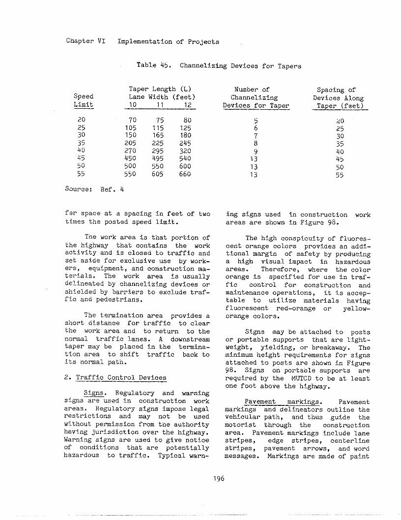
Chapter VI
Speed
Implementalion of Projects
Table 45. Channelizing Devices for Tapers
Taper Length (L)Lane Width (feet)10 11 12
~ource: Ref. 4
70 75 80105 115 125150 165 180205 225 245270 295 320450 495 540500 550 600550 605 660
I“erspace at a spacing In feet of twotimes the posted speed Iimlt.
The work area is that portion ofthe highway that contains the workact?.vityand is closed to traffic andSet aside for exclusive use by work-ers, equipment, and construction ma-terials. The work area is usuallydelineated by channelizing devices orshielded by barriers to exclude traf-ffc and pedestrians.
The termination area provides ashort distance for traffic to clearthe work area and to return to thenormal traffic lanes. A downstre~taper may be placed in the termin-ationarea to shift traffic back to!ts nomal path.
2. Traffic Control Devices—-— —
Signs. Regulatory and warning——signs are used in construction workareas. Regulatory signs impose legalrestrictions and may not be usedw?.thout pemission from the authorityhaving jurisdiction over the highway.Warning signs are used to give noticeof conditions that are potentiallyhazardous to traffic. Typical warn-
Nmber of Spacing ofChannelSzing Devices Along
Devices for Taper Taper (feet)——— —_
20: 2578 ;;
401; 4513 5013 55
ing signs used fn construction workareas are shown in Figure 98.
The high conspicuity of fluores-cent orange colors provides an addi-tional margin of safety by producinga high visual impact in hazardousareas. Therefore, where the colororange is specified for use in traf-fic control for construction andmaintenance operations, it is accep-table to utilize materials havingfluorescent red-orange or yellOw-ora~e colors.
Sf.gns may be attached to postsor portable supports that are light-weight, yielding, or breakaway. Thelninimm height requirements for signsattached to posts are shown in Figme98. Signs on portable supports arerequired by the MUTCD to be at leastone fOOt above the highway.
Pavement markings. Pavement—-—marki~gs and delineators outline thevehicular path, and thus guide themotorist through the constructionarea. Pavement markings include lanestripes, edge stripes, centerlinestripes, pavement arrows, and wordmessages. Markings are made of paint
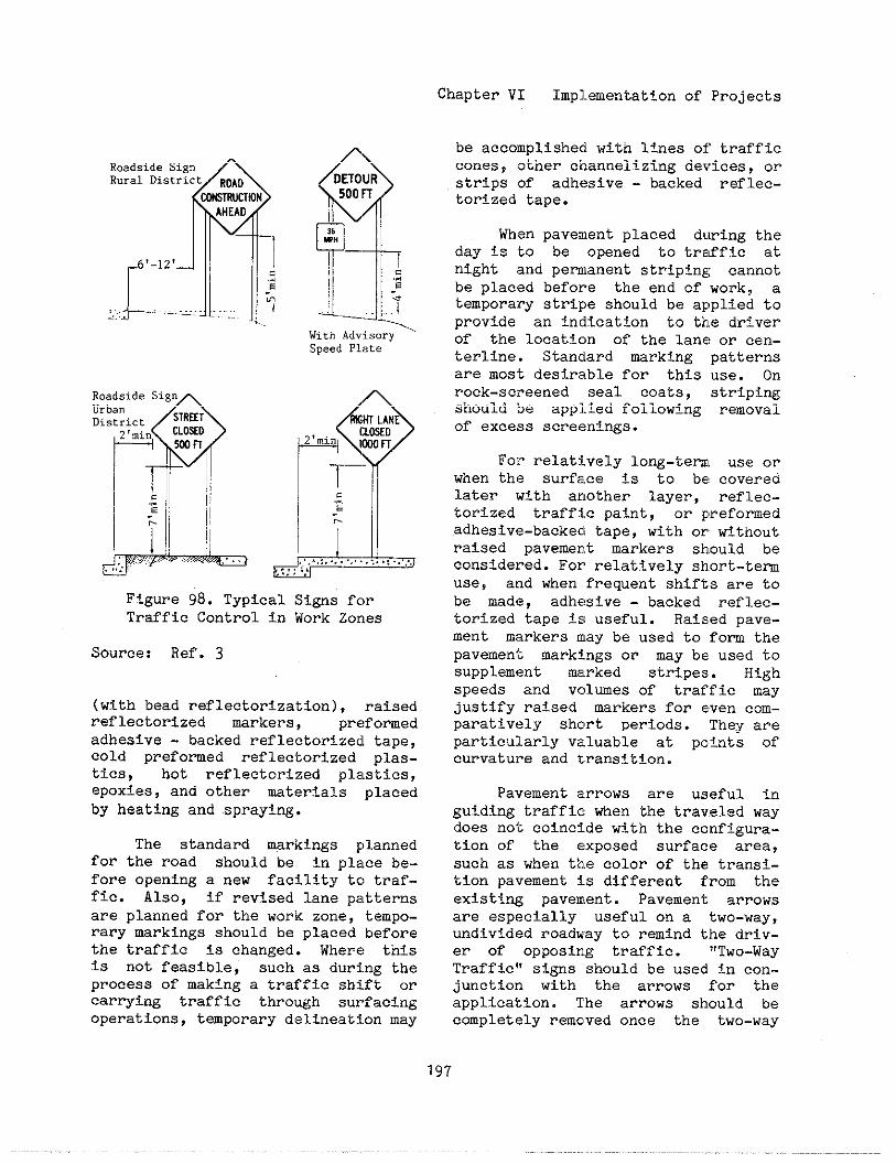
Chapter VI Implementation of Projects
QRoadside SignRural District ROAD
C~RUHIONAHEAO
6’-l2’–d
>,..L- ... ....1..., .—-—- .:..
Roadside SignUrbanDistr5ct STREET
2‘mi” CLOXO
~ p
mm
.5
~~
-,
- i
& Ii.,,,,,,,.,..,~, ,.
,,..,.
$~DETOUR500FT
:,
1
—
! ‘;-e
—.-.
With AdvisorySpeed Plate
Figure 98. Typical Signs fc)rTraffic Control in Work Zorles
Source: Ref. 3
(with bead reflectorization), raisedreflectorized markers, prc!formedadhesive - backed reflectortzecltape,cold preformed reflectorized plas-tics, hot reflectorized plnstics,epoxies, and other mterials placedby heating and sprayi~.
The standard markings plannedfOr the road should be in pl:,eebe-fore opening a new facility tc~traf-fic. Also, if revised lane pe~tternsare planned for the work zone, tempo-rary markings should be placed beforethe traffic is changed. Where! thisis not feasible, such as during theprocess of making a traffic shift orcarrying traffic through surfacingoperations, temporary delineat~.onmay
be accomplished with lines of trafficcones, ,~therchannelizing devices, orstrips of adhesive - backed reflec-torized tape.
When pavement placed dtlringtheday is ‘to be opened to trzffic atnight [~ndpermanent striping cannotbe placf~dbefore the end of work, atemporary stripe should be applied toprovide an indication to tk!edriverof the location of the lane or cen-terline. Standard marking patternsare mos’tdesirable for this use. Onrock-sc]~eened seal coats, stripi~should ioe apP1.iedfollowing removalof exce~ssscreenings.
Fe]”relatively long-tem~ use orwhen thf? surface is to be coveredlater Tiith another layer, reflec-torized traffic paint, or F,reformedadhesive-backecltape, with or withoutraised pavement markers should beconsidered. For relat~.velysb,ort-termuse, and when frequent shifts are tobe made, adhesive - backed reflec-torized tape is useful. Raised pave-ment markera may be used to fom thepavement markings or may be used tosupplement ~rked stripes. Highspeeds and volmes of traffic mayjustify raised markers for even com-paratively short periods. They areparticularly valuable at points ofcurvatul.eand transftton.
Palrementarrows are useful inguiding traffic when the traveled waydoes not coincide with the configura-tion of the exposed surface area,such as when tk~ecolor of the transi-tion pavement is different from theexisting pavement. Pavement arrowsare especially useful on a two-way,undivid(?droadway to remind the driv-er of opposing traffic. “Two-WayTraffic” signs should be used in con-junction] with the arrows for theapplication. Tbe arrows should becompletely remcved once the two-way
Chapter VI Implementation of Projects
traffic condition is no longerneeded.
Whenever traffic is shifted fromits nomal path, whether a lane isclosed, lanes are narrowed, or traf-fic is shifted onto another roadwayor a detour, cotilicting pavementmarkings should be removed. Excep-tions to this may be made for short-tem operations, such as a work zone~der flaggers’ control or moving ormobile operations. Use of ratsedpavement markl~s or removable mark-ings may be economical since they areusually easier to remove when nolonger needed.
~elineators. Delineators arereflective units with a ~inimmdimension of approxi[nately threeinches. The reflector units can heseen up to 1,000 feet under nomalconditions when reflecting the highbeams of motor vehicle headlights.The delineator should be installedabout four feet above the roadway onlightweight posts.
Delineators should not be usedalone as channelizing devices In workzones but may be used to supplementthese channelizing devices in outlin-ing the correct vehicle path. Theyare not to be used as a warning de-vice. To be effective, several delin-eators need to be seen at the sametime. The color of the delineatorshould be the same as the pavementmarking that it supplements.
Channellzing Devices. Channel-izing devices consist of cones, tubu-lar markers, vertical panels, drums,barricades, and barriers. Cones arelightweight devices that may bestacked for storage, are easy toplace and remove, and are a minorimpedance to traffic flow. They areat least 18 inches high. Cones that
are 28 inches high should be used onhigh speed roadways, on all facili-ties during hours of darkness, orwhenever more conspicuous guidance isneeded. Cones are reflectorized foruse at night with a six inch widereflectorized band placed no morethan three Inches from the top orwith a lighting device.
Tubular markers are also light-weight, easy to install, and are aminor impedence to traffic flow. Theymust be set in weighted bases or fas-tened to the pavement. They should beat least 18 inches high with taller
devices preferred for better visibil-ity. Wrkers should be reflectorizedfor use at night with two reflec-torized bands, three inches in width,placed no more than two inches fromthe top and no more than six tithesbetween the bands.
Vertical panels are 8 to 12inches in width and a minimu of 24inches in height. They are advanta-geous in narrow areas fiere barri-cades and drma would be too wide.They are mounted on lightweight postsdriven into the ground or placed onlightweight portable supports. Theora~e and white stripes on verticalpanels slope down toward the sidethat traffic is to pass. They shouldbe reflectorized as barricades andinstalled such that the top ia a min-imu of 36 inches above the highway.
Drms are highly visible andappear to be fomidable objects thuscomanding the respect of motorists.They should be mrked with horizontalorange and white stripes that arereflectorized, four to eight inchesti-de. The drm must have at leasttwo sets of orange and white stripesbut can also have nonreflectorizedspaces up to two tichea wide betweenthe stripes.
198

Barricades should be constructedof lightweight materials and areclassified as Types I, 11, and III.Types I and II are used for eitherchannelizing or marking hazards.Type III barricades are used for roadclosures. The barricade rails havealternating orange and white reflec-torized stripes that slope downtoward the side traffic is to pass.
Barriers provide a physical lim-itation through which a vehicl,ewouldnot nomally pass. They are ~sed tokeep traffic from entering ia workarea or from hitting an (exposedobject or excavation. They ]?rovideprotection for workers and co]nstnc-tion and separate two-way t]raffic.They are usually made of conc]reteormetal and are designed to contiiinandredirect an errant vehicle. IIxposedends of barriers should have crashcushions to protect traffic Or flaredends provided by extending the bar-rier beyond the clear roadside recov-ery area. Two types of crash cush-ions used in work zones are sand-fllled plastic barriers and th(?port-able “Guard Rail Energy Ab$~orbfngTeminallt.
High level warning devi(:esaretall, portable stands with fla~;sand/Or flashiu lights. Three fla~~s, 16inch square or larger, are mounted atleast eight feet above the highway.
Lighting Devices. Three typesOf warning lights may be used inconstruction areas. Flashing lightsare appropriate for use on a channel-izing device to warn of an i:jolatedhazard at night or call attent,f.ontowarning signs at night. High titen-sity lights are appropriate to use onadvance warning lights day and night.Steady-burn lights are apprc>priatefor use on a series of channe!lizingdevtces or on barriers that either
Chapter VI Implementation of
form the taper to close ashoulder, or :<eepa sectionor shoulder closed, and arepropriate on the channelizin{3devicesalongside the work area at mLght.
Projects
lane orof lanealso ap-
Work vehicles in or near thetraffic areas are hazards al~dshouldbe equipped wi’kbflashing lights suchas emergency flashers, flashingIlghta, strobes, or rotating beacons.High intensity lights are effectiveboth da,yand night. The laws of tbeagency having jurisdiction over thestreet or highway should be checkedconcerning requirements for flashfngvehicle lights. These lights shouldbe used in addition to other channel-Izing and warning devices. However,in some emergency s?-tuations, tierethe work will be in progress for ashort time, these lights may be theonly warning device.
Flashing arrow panels :Lresignswith a matrix of lights capable ofeither flashing or sequentf.al dis-plays. They are effective day andnight f,>r moving traffic o~lt of alane to the left, to the right, andmay be used for tapered lane clO-sures. These arrow panels should notbe used when no lanes are clO~ed,when there is no interference intraffic flow, nor when a flagger iscontrolling traffic on a normal twO-lane two-way road.
Flagging. Flagging sk,ould beused ~~en required to controltraffiC or when all other methods oftraffic control are inadequate towarn and dtiect drivers. Tbe proce-dures for flagging traffic are con-tained in Sections 6F-2 through 6F-7of the MUTCD. The standard signalsto be used by flaggers are !1lus-trated fLnFigure 99. Flaggers shOuldbe in sf,ght of each other or havedirect communication at all times.
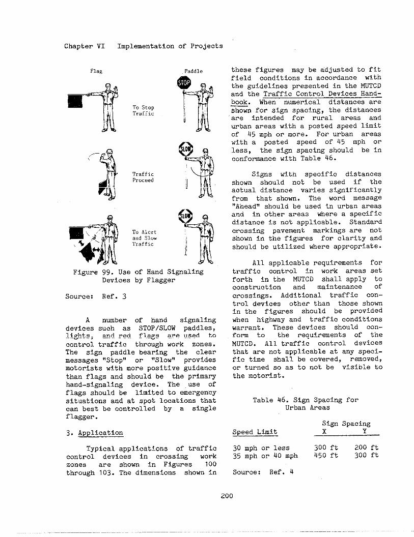
Chapter VI Implementation of Projects
t
,- :<,
-.
II.’
To StopTraffic
T,affj.cProceed
To Alert*“d S1OWTraffic
Figure 99. Use of Hand Signali~Devices by Flagger
Source: Ref. 3
A nuber of hand signalingdevices such as STOP/SLOW paddles,lights, and red flags are used tocontrol traffic through work zones.The sign paddle bearing the clearmessages “Stop” or “SICW” prcvidesmotorists with more positive guidancethan flags and should be the primaryhand-signaling device. The use offlags should be limited to emergencysituations and at spot locations thatcan best be controlled by a singleflagger.
3. Application
Typical applications of trafficcontrol devices fn crossing workzones are shorn in Figures 100through 103. The dimensions shown in
these figures may be adjusted to fitfield conditions in accordance withthe guidelines presented in the MUTCDand the Traffic Control Devices Hand-book. When nmerical distances a=shown for siKn s~acing, the distancesare intende~ f~r rural areas andurban areas with a posted speed limitof 45 mph or more. For urban areaswith a posted speed of 45 mph orless, the sign spacing should be inconfownce with Table 46.
Signs with specific distancesshcwn should not be used if theactual distance varies significantlyfrom that shorn. The word nessage,,Aheadll~hculd be used in urban areas
and in other areas where a specificdistance is not applicable. Standardcrossing pavement markings are notshown in the figures for clarity andshould be utilized where appropriate.
All applicable requirements fortraffic control in work areas setforth in the MUTCD shall apply toconstruction and maintenance ofcrossings. Additional traffic cOn-trol devices other than those shownin the figures should be prcvidedwhen highway and traffic conditionswarrant. These devices should cOn-fcm to the requirements of theMUTCD. All traffic control devicesthat are not applicable at any speci-fic time shal1 be covered, removed,or turned so as to not be visible tothe motorist.
Tabla 46. Sign Spacing fcrUrban Areas
Sign SpacingSpeed Lim?t x Y
30 mph or less 300 ft 200 ft35 mph or 40 mph 450 ft 300 ft
Source: Ref. 4
200
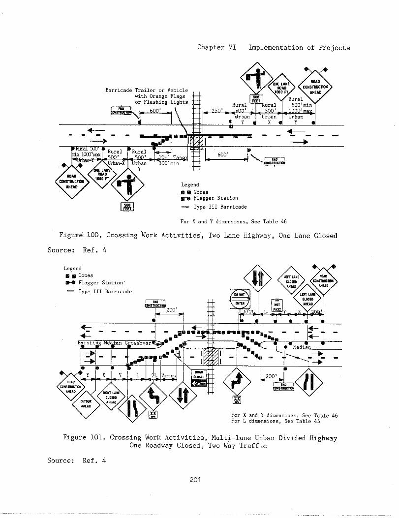
Chapter VI Implementation of Projects
~~ ~ $y<>* OEm;yE ‘0’40Barricade Trailer or Vehicle
CONSIRWTwom A“l.AD
with Orange Flags SW Ruralor Flashing Lights
Rural 500’min.W.>+, :* ~r;n ‘“’”:?: y:
d+---- - ~
---- -- ---+ d 4
4D’..W.
Legend❑ m ~~nes~ FlaggerStation
m — Type111Barricade
For X a“d Y dime”$sio”s,See Table h6
[email protected]~ossing Work Activities, Two Lane High,iay,One Lane Closed
Source: Ref. 4
~~ For X and Y dimensions, See Table 46For L dimensions, See Table 115
Figure 101. Crossing Work Activities, Multi-lane U]:ban Divided Hj.ghwayOne Roadway Closed, Two Way Traffic
Source: Ref. 4
201
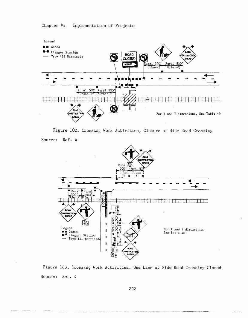
Chapter VI Implementation of Projects
Legend
mB cones~ FlaggerStation— TypeIIIBarricade
4- \“ 4+
-+-------T ‘= -------Gb b Bd
%=>
I 111! ~ I I I 1~[ I I I I I ! ! I I ! I I I ! I ! ~! I I
+
For x and Y dimensions,See Tsble 46
Figure 102. Crossing Work Activities, Closure of Side IloadCrossing
Source: Ref. 4
Figure 103. Crossing Work Activities, One Lane of Side Road Crossing Closed
Source: Ref. 4
202
Chapter VI Implementation of Projects
F. References
1. Federal-Aid Highway prOgr~ ~nzual, Washington, DC: Federal Highwayministration, updated periodically.
2. Federal Highway AdministrationSurvey of Region and DivfsioD Of-
fices, unpublished, 1984.
3. Manual on Uniform Traffic ControlDevices, Washington, DC: FederalHighway Administration, 1978, Revisedlg7g, 1983, 1984.
4. Traffic Control Devices Handbook,Washington, DC: Federal HighwayAdministration, 1983.

The railroad - highway gradecrossing is unique to other highwayfacilities in that railroads design,install, operate, and maintain thetraffic control devices located atthe crossing. Even though a largeportion Of the cost of design andconstruction of crossings, includingtraffic control devices, is assmedby the public, cu;rent proceduresplace maintenance responsibility withthe railroads. The public agencyhaving respossibility for the mainte-nance of the roadway approaches gen-erally teminates its mainte~nceresponsibility for the roadway at thecrossing surface. Traffic controldevices on the approach~ in mostinstances, is the full responsibilityof the public agency.
Railroad personnel maintain thedevices at the crossing and theircontrol circuitry. Highway trafficsignals located near the crossing maybe preampted utilizing the sae traindetection circuitry as the signals atthe crossing. Where this !~ccurs,coordination of railroad and l~ighwaymint enance activit?-esis essentialto safe and efficient traffic opera-tion.
Nomally, railroad maintenanceof traffic control devices is accom-plished as a part of the regularmaintenance progrm for signals cOn-trolling train operations. Railroadsignal maintenance personnel are sta-tioned at specific locations alongthe railroad line and are responsiblefor all signal maintenance withintheir assigned territories. Gener-ally, the maintenance of crossingdevices is only a portion of therailroad signal maintainer’s daily
activi:Ly. Although there are cur--rently no Federal safety regulationsspecifically addressing the mainte-.nance of these devices, a few Stat<!regulatory agencies have establishedregulations for their maintenance.All ra~.lroadcompanies have Lnstmc-tions for the inspection and mainte-nance of the devices.
The maintenance of crosstig sur-faces is perfomed by another depart-ment of the railroad. The Maf.ntenanceof Way Department of the railroadcompany has responsibility for alltrack~ roadbed and drainage mainte-nance. Maintenance of surfaces isusually a part of the railroad’speriodic track maintenance program.
Site specific maintenance is per-fomed only fn emergencies or uponspecial request.
The highway agency is usuallyresponsible for maintaining the high-way approaches, all traffic controldevices on the approaches, except thecrossbuck sIgn, ill~ination, andspecial signtng at the crossing suchas the “Exempt” sign, the “DO NotStop On Tracks” sign, and the stopsign.
An open channel of communicationbetween the local matitenance staffof the highway agency and the rail-road company 3s essential. Each high-way agency maintenance foreman shouldhave a railroad company telephonenmber available on a 24 hour basisto repo]”tcrossing device failure ormalfunction. In additfon, the rail-road signal maintainer should estab-lish and maintain contact wtth thehighway agency maintenance supervi-sor(s) in the signal maintainer’sassigned territory.
Chapter VII Maintenance Program
The U.S. DOT/AAR inventory nw-ber assigned to the crossing shouldbe used in any communication betweenrailroad and highway maintenance per-sonnel. This requires that the inven-tory nwber board be displayed ateach crossing and properly main-tained.
Highway maintenance personnel,during the course of their nomaltravel, should be encouraged to be onthe lookout for dmaged or malfunc-tioning crossing traffic control de-vices. To ensure the proper reportingof devices in d!srepair, the railroadsignal department should infom high-way agency personnel as to how andwhy the devices operate and what con-stitutes failure. A procedure forreporting dmaged or malfunctioningdevices should be developed. In Texasthe State highway agency has postedsigns at all crossings on the Statehighway system. These signs requestnotification of devices in disrepair.A tol1 free nmber along with thecrossing inventory nmber is includedon the sign that Is momted on theflashing light signal post.
The htghway agency maintenanceprogra should follow normal highwayinspection and maintenance proce-dures. For exaple, both signs andpavement ~rkings should be inspectedduring both daylight and nighttimeconditions every three to six months.This inspection should include thecondition and adequacy of reflectiv-ity of the signs and markings. Pave-ment marking experience at a particu-lar locale may indicate an approxi-mate interval between repainting 0p-erations. Such a determination willpemit the progr-ing of repainti~into the overall striping progrm forthe area. However, periodic inspec-t~on should not be eliminated in anY
case as spilled loads, resurfacingand other occurrences nay obllte~ate
the markings. Sign deterioration isonly one of several factors to beconsidered in sign maintenance. Ofequal or greater importance are van-dalism and inadvertent dmage. Care-ful choice of material, momt%wheight and mounting technique canreduce dmage from vandalism. D~agecaused by accidents can be con-strained through regular inspectionand repair.
The maintenance of the sighttriangle, beyond railroad right-of-way, presents a unique problem. Ex-cept for the portion of the sighttriangle within the roadway right-of-Way, most of the sight triangle in-volves private property. The removalof trees, vegetation, crops, buSld-ings, signs, storage facilities, andother ObstruetiOns to the dr?ver’sview of an approaching train requiresaccess to the property and an agree-ment with the property owner for theremoval of the Obstruction.
Some maintenance activities ator near crossings may require trafficcontrol. The procedures specified inChapter VI for traffic control inconstruction areas are applicable tomaintenance activities as well.
In addition to their usualresponsibility for the maintenance ofthe crossing surface and traffic con-trol devices at the crossing, rail-roads also maintain sight clearancewithin railroad right-of-way. Thisincludes vegetation control, removalof unused railroad buildings andplacment of rail cars.
Since these maintenance activ-ities are a part Of rout?ne railroadsignal and maintenance-of-way aCtiV-ity, site specific maintenance costsare difficult, if not impossible, tocalculate. As with most Federal high-way funding progrms, maintenance
Chapter VII Maintenance Progra
expenditures associated with crOss-ings are not reimbursable under theprogra. However, 17 States and a fewlocal governmental agencies havepassed legislation authorizing con-tribution, by the State, to the main-tenance of crossing surfaces and/ortraffic control devices located atthe crossing. Finding for these pro-grms is either by State legislatureappropriations or by local ordinance.Appendix B contains infomaticn onState maintenance progrms.
Such maintenance agreements be-tween a railroad and a State mustcontain mutually agreed to defini-tions of eligible devices. In sOmecases, the devices are defined asflaahing lights only or flashinglights and gates, with specificationof the nuber of tracka. Or, trafficcontrol devices my be defined interns of AAR units. Railroad signalSystas are comprised of componentparts, each of which (individually orin combinations) have been assignedrelative unit values by the Associa-tion of berican Ratlroads (AAR). Therelative unit values were developedfor accounting and record purposesdirected toward determining installa-tion, replacement, maintenance andoperating costs on an industry-wideunifom basis. Comittees of the AARhave established recommended prac-tices for the application of these~its. A 1982 AAR technical reportclassifies the following types ofcroaaing traffic control systems byAAR units.
o Type I -- Standard flashing lightsignals at single track, averageAAR units 13.85
0 Type II -- Standard flashiq; lightsignals tith gates at singletrack, average AAR units 23,*89
o Type III -- Cantilever type sig-nals at single track, average AARunits 18.23
0 Type IV -- Cantilever type signalswith gates at single track, aver-age AAR Wits 27.81
0 Type V -- Standard flashing lightsignals with gates at two maintracks, average AAR mits 34.30
0 Type VI -- Cantilever type signalswith gates at two main tracka,average AAR units 36.04
0 Type VII -- Special layout withmultiple gates and tracks, averageAAR Lmits 48.25
The AAR wit method for definingcrossing maintenance provides an op-portunity for negotiating a specificdollar value for each unit and thenapplying this value to any combina-tion of units. Dollar values arereportecl for AAR units in the 1982publication. These values, if used,should be adjusted for current ecO-nomic conditions.
Any method used for the reim-bursement of matitenance costs sho!lldconsider the components of mainte-nance. Maintenance costs are cOm-prised of equipment, material, labor,tranaportationp atiinistratiOn, ac-counting, and training costs. Laborcosts involve the hourly wage andbenefits received by the ~ailroad,State, local goverment, or contrac-tor employee. Materials associatedwith maintenance include the spareand replacement parts as well as thetools needed for repair. Transporta-tion must be provtded fOr laborers
and mater%als.
Chapter VII Maintenance Program
B. References
1. Federal Highway AtiinistrationSurvey of Region and Division Of-fices, unpublished, 1984.
2. !!MaintenanceCost Study Of Rail-
rOad-Highway Grade Crossing WarningSystms ,*!Wa~hingtOn, DC: Association
of kerican Railroads, October 1g82.
VIII. EVALUATION OF PROJECTS AWD PROGRW
An integral part of any rafl-road-highway grade crossing improve-ment program is the evaluation ofindividual projects and the OVeral~program. The Federal - aid Hi&~a~Program Manual (FHPM), 8-2-3, sPeci-fies that‘em State’s highway safetytiprovement program should include anevaluation of the progra. Thiseval,~ationcomponent Is to fnclude adetermination of the effects theimprovements have in reducing a~cci-dents, accident potential, and scci-dent severity. This process skiouldinclude:
o the cost of, and the safety bene-fits derived from, the vaz,fOusmeans and methods used to mitf.gateor eliminate hazards;
0 a record of accident exper:Lencebefore and after the implementa-tion of a highway safety improve-ment project; and,
0 a comparison of accident nwbers,rates, and severity observed afterthe tiplementation of a highwaysafety improvement project withthe accident nwbers, rates, andseverity expected if the imp]eove-ment had not been made.
In addition, the evaluation pro-gram is to include an annual evalua-tion and report of the State’s over-all safety improvement program andthe State’s progress in implementingthe individual Federal progras, suchas the Section 203 crossing progrm.
Evaluation is an assessment Ofthe value of an activity as measuredby its success or failure in achiev-ing a predetermined set of goals Orobjectives. The ultimate goal of
evaluattor~is to improve the agency’Sability to make future decisionsregarding the improvement progrm.These decisions can be aided by con-ducting formal effectiveness and ad-mfnistrative evaluations of ongoingand comp].eted improvement projectsand progrms.
In the Highway Safety Evalua-tion, Procedural Guide, two types of__—evaluation are addressed: effective-ness evaluation and administrativeevaluation. These two types of eval-uation Will be discussed in ttischapter only in sufficient detail forthe user to be aware of the need forit and the procedwes. However, thereader should refer to the ProceduralGuide fol-more details. Also, the——followlng references provide moreuseful information on safety evalua-tion procedmes.
0
0
0
0
Lunenfeld, H. Evaluation of Traf-fic Operations, Safety and posi-‘~u=~s, Washing-ton, DC: Federal Highway Adminis-tration, Report No. FHWA-1o-80-I,October 1980.
Tarrants, W.E. and Veigel, C.H.,~he Evaluation of Highway TrafficSafety Programs, Washington, DC:National Highway Traffic SafetYAdministration, Report DOT-HS-80-
525, Febnary 1978.
Comcil, F. lti.et al., AccidentResearch Manua~, Washington, DC:Federal Htghway Administration,Report FHwA/RD-80/016, February1980.
Berg, W. D., Expertiental Design~r Evaluating the Safety Benefitsof Railroad Advance Warning Signs,
Chapter VIII Evaluation of Projects and Progras
Washington, DC: Federal HighwayAtiinistration, Report FHWA-RD-7g-7a, April 1979.
A. Project Evaluation
Improvements to railroad-highwaygrade crossings that have aS theirobjective the enhancement of safetyshould be evaluated as to their ef-fectiveness. This can be done for in-dividual projects and should be donefor the overall improvement progrsm.An effectiveness evaluation for safe-tY purposes is the statistical andeconomic assessment of the extent towhich a project Or program achievesits ultimste safety goal of ~educi~g
the number and/or severity of acci-dents. It also can be expanded toinclude an assessment of the inter-mediate effects related to safetyenhancement. The latter type evalua-tion becomes particularly relevantfOr crossings because the low nwberof accidents occurring at a crossingmay preclude any meaningful accident-based evaluation of individual cross-ings or a smll nmber of them.
The Procedural Guide lists sevenfunctions—that should b: followed inconducting an effectiveness evalua-tion.
o Develop an evaluation plano Collect and reduce data0 Compare measures of effectiveness0 Perfom statistical tests0 Perform economic analyseso Prepare evaluation docmentso Develop and update a data base
The essential elements of theprincipal funct?.ons are described
below.
The evaluation plan addressessuch issues as the selection of: 1)projects for evaluation; 2) project
PurPOses; 3) evaluation objectivesand measures of effectiveness; 4 ) ex-perimental plans; and, 5) data re-quirements.
While it would be desirable toevaluate all improvement projects,mnpower and fiscal capabilities donot always pemit this. Consequentlywhen selecting projects for evalua-tion, the followi~ factors should beconstdered.
0
0
0
Improvement types that are ques-tionable as to their effectiveness
Projects that have sufficient datanecessary for statistical analysis
Projects that are directly relatedto accident reduction -
If the nuber of accidents oc-curring before the improvement fs toofew to allow a significant reductionof accidents to wcur, the project
~Y be evaluated along with othersimilar projects. This is frequentlythe situation with crosstigs sineethey experience very few accidents.If projects are aggregated fOr eval-uation, it is essential that the:
0
0
0
Countermeasures for each be iden-tical;
types Of locations be similar;and,
project purposes be similar.
The experimental plan selectedshoxld be consistent with the natweof the project and the completenessand availability of data. The mostcomon experimental plans for evalua-ting safety improvement projects are:1) before and after study with con-trol sites, and 2) before and afterstudy.
210
Chapter VIII Evaluation of Projects and Progras
The most desirable meas~lre ofeffectiveness (MOE) for cr,ossingsafety improvements would be the re-duction of accident frequency or se-verity. However, since a long periOdof time may be required to ~~lSS anadequate saple size, especially forindividual projects, evaluations canbe made based on other measures suchas:
o traffic performnee - speed,,stop-ping behavior, and conflfcts, or
o driver behavior - looking, com-pliance, and awareness.
The evaluation plan describesthe types and amounts of data neces-sary for the evaluation. Data forthe before situation could be ob-tained from the engineering study(see Chapter III) used to asaist indetermining the crossfng problem andappropriate improvement. Additionaldata, if not available from histori-cal records, till have to be col-lected before the tiproveme]tt ismade. If the measure of effective-ness involves accident data, severalyears of data would be required.Traffic and driver behavior data canbe collected four to six weeks afterproject implementation.
The effect of the project(s) ontbe selected MOE must be detemined.Computations are made tO dete~inethe expected value of the MOE if theproject(s) had not been implementedand the difference between the ex-pected MOE and the actual observedvalue of the MOE. This differenceshould then be tested to determine ifit is statistically significant.
An important objective of an ef-fectiveness evaluation is to obtain acomplete picture of how well the com-pleted project is perfoming from asafety standpoint. Economic analysis
provides another perspective. Fromsuch analysis, an assessment of costand accident reduction effects, incombination, may be made. This aspectof an evaluation is very important asit is possible to have a very effec-tive project that is cost-prohibi-tive in terns of future use undersimilar circumstances.
There are many economtc analysistechniques. The two most Comonlyused fo]eevaluating completed highwaysafety improvement projects are thebenefit/cost (B/C) and cost/effec-tiveness (C/E) methods.
An effectiveness data base is anaccwulation of project evaluationresults that are directly usable asinput to future project seleCtiOn.The data base:
0 contains pertinent infO~atiOn onthe accident reducing capabilitiesof countermeasures and/or proj-ects;
o must be continually updated withnew effectiveness evaluation in-fomat ion; and!
o should only conta?n evaluationresults from reliable and properlyconducted evaluations.
With such a data base, accidentreduction factors can be establishedand refined over time. These factorsin turn. can be used in dstemini~the most cost-effective improvements.
B. Pro~- Evaluation
Thle preceding section outlinedthe process for conducting evalua-
tions of one or more improvementp~~ject,s. This evaluation prOcess can
and should be applied to the entirecrossing improvement program or cOm-
Chapter VIII Evaluation of Projects and Progrms
ponents of it. The entire progrmwould consist of all those activitiesincluding physical improvements tothe crossing, changes in railrOad Orhighway traffic operations, andchanges in law enforcement and indriver education.
Throughout the pro~a it may beuseful for the policy mker to iden-tify whether certain specific progrmsubsets are effective. These prograsubsets could fnclude types of im-provements such as:
0
0
0
0
0
installation of flashing lights;relocation of crossing;illminatiOn;sight distance improvements; or,combinations of two or more types.
The steps and procedwes in con-ducting the progrm, or subset of theprogra, effectiveness evaluation areessentially the same as for projects.
FHWA’s Procedural Guide should bereferred~~o~-d~
C. Atiifistrative Evaluation
This evaluation is the assess-ment of the scheduling, design, con-struction, and operational reviewactivities undertaken during the im-plementation of the crossing improve-ment progrm. It evaluates these ac-tivities in terns of actual resourceexpenditures, planned versus actualresource expenditures, and produc-tivity.
In the FHWA Procedural Guide,—-eight steps are recommended foratiintstrative evaluation as listedbelow.
o Select evaluation subjects
o Review project (progrm) details
0
0
0
0
0
0
D.
1.
Identify atiinistrative issues
Obtain available data sources
Prepare atiinistrat;.ve data sm-mary tables
Evaluate administrative issues
Prepare andtion report
Develop and
References
distribute the evalua-
update data base
Berg, William D., ExperimentalDesign for Evaluating the SafetyBenefits of Railroad Advance Warningm, Washington, DC: Federal High-way Atiinistration, Report FHWA-RD-79-78, April 1979.
2. council, F.M. et al., A~~identResearch Manual, Washington, DC: Fed-eral Highway Atiinlstration, ReportFHwA/RD-80/016, February 1980.
3. Federal-Aid Highway Program Man-——ual, Washington, DC: Federal HighwayAtiinistration, updated periodically.
4. Goodell - Grivas, Inc., HighwaySafety Evaluation Procedural Guide,Washington, DC: Federal HighwayAtiinistration, FHWA-TS-81-219, OCtO-ber 1980.
5. Lunenfeld, H. Evaluation of Traf-fic Operations, Safety and Positiveguidance Projects, Washington, GFederal Highway Atiinistration, Re-port No. F~A-1 0-80-1, October 1980.
6. Tarrants, W.E. and Veigel, C. H.,The Evaluation of Highway TrafficSafety Atiinistration, Report DOT-HS-~5, February 1978.
212
,.
1,X.SPECIM ISSUSS
There are several issues thatare important to railroad - highwaygrade crossing safety and operationsthat either were not specificallycovered in previous chapters or thatwarrant special consideration. These?.ncludeprivate crossings, short linerailroads, high speed rail corridors,pedestrians, bicycles and motor-cycles, and special vehicles.
A. Private CrOssi~s
Private railroad-highway gradecrossings are those that are on,road-ways not open to use by the publicnor are they maintained by a publicauthority. According to the U.S.DOT/AAR National Rail-Highway Cross-fng Inventory, in 1983 there were133,011 private crossings in theUn~.tedStates. Usually, an agreementbetween the land owner and the rail-road governs the use of the privatecrossing.
Typical types of private CrOSS-ings are as follows.
o Farm crossings that provide accessbetween tracts of land lying onbotb sides of the railroad
o Industrial plant crossing5 thatprovide access between plantfacilitateson both sides of therailroad
o Residential access crossings overwhich the occupants and theirfnv:tees reach private residencesfrom another road, frequently apublic road paralleling and adja-cent to the railroad right-of-way
o Temporary crossings establishedfor the duration of a private
construction project or other sea-sonal acttvity
In some instances, changes inland use have resulted in an expan-sion of a crossing’s use to theextent that it has become a publiccrossing as evidenced by frequent useof the general public. This may occurwhether or not any public agency hasaccepted responsibility for maint-enanceor control of the use of thetraveled way over the crossing. Therailroad and highway agency shouldcontinually review the use of privatecrossings so that mutual agreement isobtained on its appropriate classifi-cation. If the general public tsmaking use of the crossing, appro-priate traffic control devices shouldbe installed for thetr warning andgutdance. Usually, State and Federalfunds are not available for use atprivate crossings.
The nuber of accidents at pri-vate crossings represent a Smllportfon of all crossing accidents;however, safe design and operation atprivate crossings should not be Over-
looked. Very few private crossingshave active traffic control devicesand many do not have signs. Typical-ly, they are on narrow gravel roadsoften with poor roadway approaches.
In 1983, there were 599 acci-dents, 33 fatalities, and 156 in-juries at prtvate crossings. Theserepresent reductions, since 1979, of37.4$ in accidents, 32.7% in fatal-ities, and 24.3% in injuries as shownin Table 47.
As with accidents at publiccrossings, the majority of acctdentsat private crossings involved automo-biles. Table 48 gives the nuber of
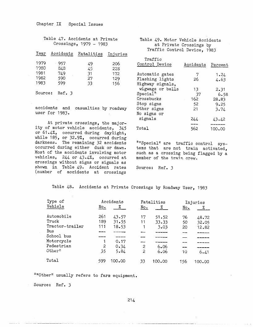
Chapter IX Special Issues
Tabls 47. Accidents at PrivateCrossings, 1979 - 1983
Tabls 49. Motor Vehicle Accidentsat Private Crossings by
Traffic Control Device, 1983~ Accidents Fatalities Injuries
1979 957 2061980 848 $ 2281981 749 31 1721982 590 I291983 599 z 156
TrafficControl Device Aacidents Percent
Automatic gatesFlashing lightsHighway signals,wigwags or bellsSpecial*CrossbucksStop signsOther signsNo signs orsignals
726
1.244.63
13
3?162
52
2.316.58
28.839.25
3.74
Source: Ref. 3
accidents and casualties by roadwayuser for 1983.
21
244---
562
43.42At private crossings, the major-
ity of motor vehicle accidents, 345or 61.4%, occurred during daylight,while 185, or 32.9%, occwred duringdarkness. The remaining 32 accidentsoccurred during either dusk or daw.Most of the accidents involving motorvehicles, 244 or 43.4%, occurred atcrossings without signs or signals asshorn in Table 49. Accident rates(number of accidents at crossings
------
Total 100.00
*!!Specialtyare traffic control sys-tems that are not train activated,such as a crossing being flagged by amember of the train crew.
Source: Ref. 3
Table 48. Accidents at Private Crossings by Roadway User, 1983
Type ofVehicle
AccidentsNo. z——
FatalitiesNo ~4
InjuriesNo %J_
AutomobileTruckTractor-trailerBusSchool busMotorcyclePedestrianOther*
261 43.57189 31.55111 18.53--- -----
17 51.5211 33.33
1 3.03
76 48.72
50 32.0520 12.82-- _____-- _____
--- ____
1 0.170.34
3: 5.84
-- ----- -- ------- ------- _____
2 6.06 -- _____
10 6.412 6.06
Total 599 100.00 33 100.00 156 100.00
*!Iother!1usually refers to farm equipment.
Source: Ref. 3
21L

Chapter IX Special Issues
with each typedevice dfvtded bywith that t~ue
of traffic c~ntrolnumber of crossingsof traffic control
device) cann~~ be detemined forprivate ~rOssings since no natfonalstatistics are kept on the type oftraffic control devices at privatecross?.ngs.
Some States and railroads haveestablished minimum Signing require-ments for private crossings. Typical-ly, these signs cons~st of a crOss-buck, stop Siw, andlor a warningagainst trespassing. California andOregon public utility commiss~Onersuse a standard highway stop signtogether with a sign indicating thatthe crossing is a private crOss~ng.A typical configuration is shown inFigure 104.
As with public crossings, thefirst consideration for improv?ngprivate crossings is closure. Adja-cent crossings should be evaluated todetermine if they can be used instead
;!
F~~~~e 104. Typical Priva~Le
Crossing Siw
Source: Ref. 1
of the private crossing. Every effortto close the crossing should be made.
If the private crossing is de-termined to be essential to the pri-vate landowner, then the crossingshould be mrked with some type ofsign. Controversy exists over wheth-er the marking sho~ld be identical topublic crossings so that the motoristis presented with unifom trafficcontrol devices, or whether the mark-ing should be distinct to notify themotorist that the crossing is privateand that use without pemission istrespassing. No national guidelinesexist; however, tt seems reasonablethat the crossing should be marked sothat it is identified as a privatecrossing. Supplemental crossbucks orstop signs might also be installed.
Some private crossings have suf-ficient train and roadway trafficvolme that they require active traf-ftc control devices. Cons?.derationsfor the installation of these devicesare the same as for public crossings,as discussed in Chapter IV. Federalfunds, and often State fwds, cannotbe used for the Installation of traf-fic conl;rol improvewnts at privatecrossings. The railroad and the land-owner ,~suallycae to an agreementregarding the f!-nanctng of the de-vices. In some cases, if the land-owner is required to pay for theinstallation of the crossing and itstra~fic control devices, the land-owner might reevaluate the need forthe cross%ng.
B. Short Ltie Railroads
There are nmerous short line~~il~~~d~ and the nmber is growingdue to Federal deregulation. Shortline railroads are typically Class111 railroads, as defined by theInterstate Commerce Commission (ICC ).
Chapter IX Special Issues
class III railroads Include allswitching and terminal companies andall line-haul railroads that have anannual gross revenue of less than $10million, in 1978 constant dollars.Many of these short line railroadsprovide switchtng and terminal serv-ices fOr the larger Class I and IIrailroad companies. Many of the shOrtline railroads belong to the AmericanShort Line Railroad Association(ASLRA). Headquartered in Washington,DC, the ASLRA provides liaison withgovernmental agencies, serves as aSOUrCe fOr information and ~SS is-
tance, and provides other benefits toshort line railroads.
Some short line railroads tookover the operatfon of a stngle linethat a larger railroad abandoned foreconomic reasons. Short line rail-roads often require assistance withregard to railroad - highway gradecrossings because of their limitedmanpower and financial resources.These smll railroads ape oftenunable to seek out Federal and Statefunds for improving crossfngs, yetsafety at their crossings is just asimportant as at any other crossing.
Ownership of these smaller linesare from a variety of investmentsources such as, State or local gov-ernments, port authorities, othershort lines, private entrepreneurs,and sh?.ppergroups. Many new ownersof short lines are keenly aware ofcosts of line acquisition, track androlling stock rehabilitation, alongwith other operational expenditures.Yet, new operators may be unaware ofthe substantial expenditures neededfor rebuilding crossing surfaces,renewing older traffic control sys-tems, and maintaining them.
Costs associated with crossingsmay comprise a considerable portionof the llmtted annual maintenance-of-
way budgets of short line railrOads.The general condition of the aban-doned plant, as acquired by the newowner, is usually far from best. Thetrack condit+-on my be adequate,requiring relatively little annualexpense in comparison to other plantneeds. Therefore, as annual trackmaintenance ~O~t~ are ~ed”ced, cros~-ing expenditures may constitute as
much as 50% of the annual mainte-nance-of-way budget over the next 10years. Thfs, of course, depends onfactors such as the location of theline in relation to population cen-ters, and intensities of heavy truckt~affic.
On short line raiiroads, thereis often a lack of specialized per-sonnel for handling the many crossingresponsib?.lities,such as the contin-uing maintenance of highly complexelectronic crossing traffic controlequipment.
While rail traffic on the smal-ler lines generally tends to besparse~ as well as slow, these cross-ings, fn comparison to the largerrailroads are not necessarily safer.National statistics indicate that thevast majortty of crossing accidentsoccur at relatively low train speeds.
Adequate planning is essentialto ensure the proper fomation of newshort I.ine railroads and to imprOVetheir survival as a necessary part ofthe natton’s transportation system.When dealing with short line rail-roads, State agencies should be awareof their limited experience, skills,and knowledge. State agencies canassist by informing short line rail-roads of the requirements for improv-ing crossings on their system anddirect them to other appropriatesOurces of information. State agen-cies should ensure that the shortline railroads operating in their
216
Chapter IX Special Issues
State are included in the lines Ofcomunicat ion regarding crossings.Short line railroads also should beencouraged to participate in othercrossing safety programs such asOperation Ltfesaver.
C. High Speed Wil Corridors
Special considerations must begiven to railroad - highway gradecrossings on high speed passengertrain routes. The potential I?or acatastrophic accident! injuring mnypassengers, demands special atten-tion. Not only does this i]>cludededicated routes with speeds ovsr 100mph, but also other passenger routesover which trains my opera:~e atspeeds higher than freight trailts.
Variation in warning time atcrossings equipped with active traf-fic control devices my occur withhigh speed passenger trains. Becauseof the wide variation in train speeds(passenger trains versus fre?ghttrains), train detection circuitryshould be designed to provide theappropriate advance warning for alltrains.
High speed passenger trains pre-sent additional problems at crossingswith only passive traffic controldevices. Safe sight distance alongthe track from a stopped positionmust be much greater for a fastertrain. The sight distance along thetrack from the highway approach mustalso be greater unless vehicle speedis reduced. In addition, it iS dif-ficult to judge the speed of anoncoming train.
Private crossings are a majorconcern for high speed passengertrains. These crossings usually haveonly passtve traffic control devicesand often consist of narrow, unimp-
roved or gravel roads with lfmitedvisibility along the raflroad tracks.
Special attent!on should be giv-en to crossings on high speed railpassengel~routes. Some States utilizepriority indices that include a fac-tor for train speed or potential dan-gers to large nmbers of people. Inthis mnner, crossings with highspeed passenger trains are likely torank higher than other crossings andthus be selected for crossing im-
provements.
Another method for improvingcrossings on high speed passengerroutes is to utilize the systemsapproach. As dfscussed in ChapterIII, the systems approach involvesthe inspection and evaluation ofsafety and operations at crossingswithin a specified system, such asalong a high speed rail corridor.
It is desirable that all cross-ings located on high speed rail cor-ridors either be closed, grade sepa-rated, or equipped with automaticgates. The train detection circuitryshould provide constant warning time.Where feasible, other site improve-ments may be necessary at thesecrossings. Sight distance should beimproved by clearing all unnecessarysigns, parking, and buildings fromeach quadrant. Vegetation should beperiodically cut back or removed.Improvements in the geometries of thecrossing should be made to providethe best braking and accelerationdistances for vehicles.
EdLlcationof the public is animportant element for the improvementof safety and operations at crossingson high speed rail corridors. Thiscan be accomplished by publicity cm-paigns and public service announce-ments as described in the next chap-ter. Public education might also
Chapter IX Special Issues
alleviate some fears of hightrains and provide for betterroad-co~unity relatlons. Stateties and railroads sho~~ldtively undertake thispublic education capaign.
Special signing mightemployed at these crossings
speedrail-agen-
cOOpera-important
also beto remind
the public that it is used by highspeed trains. No national standardexists fOr such signing; however, thesigning should be in conformance wf-thth~ gu~delines provided in the Manualon Unifom Traffic Control D==mr):-—’”––——-—
D. SQecfal Vehicles, Pedestrians,Motorcycles,and Bicycles
Railroad-highway grade crOsSingSare designed and controlled to accom-modate the vehicles that use them.The vast majortty of these vehiclesconsist of automobiles, buses, andall types of trucks. Generally speak-ing, improvements to the crossi~with these users in mind will beadequate for any other special userssuch as trucks carrying hazardousmaterials, long-length trucks, schoolbuses, motorcycles, bicycles, and pe-destrians. However, these users haveU*<que characteristics and specialneeds which should ba comidered.Chapter II discussed some of thesecharacteristics. This chaptar willpresent some design and controlconsiderations.
1. Trucks with Hazardous Material—-CargO
Accf.dentsinvolving trucks withhazardous material cargo are poten-tially the most dangerous becausethey can have deleterious effectsover a wide area. Consequently, allcrossings which are used by thesevehiclas should be cons!.dered for
improvementstiprovementsspecial needs
and, Ln turn, theseshould consfder theof these vehtcles.
Dra@-ng on the National Trans-portation Safety Board’s study oftrain accidents involving these vehi-cles, and their subsequent recomme-ndations, there ara several suggestedways to address this concern.
0
0
0
0
Trucks carrying buy~ hazardousmatertals should use routes thathave grade separations or activecontrol devices. mere routes thathave crossings with only passivecontrol devices are near temi-nals, the crossings should beconsidered for upgradtng to activecontrol.
Insure that active warning devicesprovide sufficient warning time sothat trucks have available thedistance required for stOQping.Also, for vehicles that arestopped at the crossing when stg-nals are not operating, adequatewarning time should be providedfor clearance of tracks by loadedtrucks before the arrival of atrain.
If feasible, where there is anintersection in close proximity tothe crossing, increase the storageroom between the tracks and theintersecting highway. If on a dT-rect route to a truck teminal,also consider giving right-of-wayto the critical movement throughcontrol measures.
Promote a progrm of education andenforcement to reduce the frequen-cy of hazardous driving and alertthe driver of potential danger.Operation Lifesavar prograsshould be expanded to include aspecific program which addressesthe problems.
218
Chapter IX Special Issues
At crossings where there is asignificant volme of trucks that arerequired to stop, Considerateionshould be given to providing a pull-out lae. These auxiliary lanes allowthe trucks to come to a stop and thento cross and clear the tracks withoutconflicting with other trafffc.Hence, they minimize the likelihoodof rear-end collisions or other vehi-cle-vehicle accidents. They would beappropriate for two-lane highways orfor high-speed multilane highways.
2. Long and Heavily Laden Trucks_ —_
As discussed in Chapter II,large trucks kve particular problemsat crossings because of their lengthand perfornance characteristics.Longer clearance times are requiredfor longer vehicles and those slow toaccelerate. Also, longer braking dis-tances become necessary when trucksare heavily laden, thus reducingtheir effective braking capability.
With the passage of the SurfaceTransportation Assistance Act of1982, there will likely be both long-er and heavier trucks. Consequently,when considering improvements, thedesigner should be aware of, anddesign for, the mount and type ofcurrent and expected truck traffic.
Areas that should be focusedupon fnclude:
o longer sight distances;
0 ?lacement of advance warningsigns;
0 warning time for signals;
0 ~~rh and,
0 storage areanearby highway
departure grades;
between tracks andintersection.
3. Buses—.- _
Since buses carry many passen-gers and have perforwnce character-istics similar to large trucks, thesevehicles also need special considera-tion.
Many of the measures suggestedfor trucks with hazardous materialsapply to buses. Ratlroad - highwaygrade crossings should be taken titoconsideration when planning schoolbus routes. Potentially hazardouscrossings should be avoided if possi-ble. Crosstngs along school busroutes should be evaluated by theappropriate highway and ratlroad per-sonnel to identify potentially dan-gerous crossings and the need forimprovements. Dr?.versshould be in-structed on safe crossing proceduresand be mde aware of expected rail-road operations, such as the speedand frequency of train movements.
4. Motorcycles and Bicycles—.——————-
Although motorcycles and bScy-cles typically travel at differentspeeds, these two-wheeled vehiclescan experience the same problem atcrossings. Depending on the angle andtype of crossing, a cyclist may losecontrol of the vehicle <f the wheelbecomes trapped in the flangeway. Thesurface materials and the flangewaywidth and depth must be evaluated.The more the crossing deviates fromthe ideal 90-de~ee crossing, thegreater the potential for a cyclewheel to be trapped in the flangeway.If the crossing angle is less than 45degrees, consideration should be giv-en to widening the bikeway to allowsufficient width to cross the tracksat a safer angle.
Other than smooth surface treat-ments, there are no special controlsfor these special vehicles. However,
219
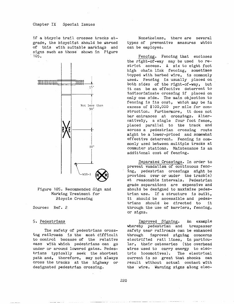
Chapter IX Special Issues
if a bicycle trail crosses tracks at-grade, the bicyclist should be warnedof this with suitable markings and
signs such as those show in Figure105.
4, J15‘
Figure 105. Recomnded Sign andMarking Treatment forBicycle Crossing
Source: Ref. 2
5. Pedestrians—.
The safety of pedestrians cross-ing railroads is the most dtfficultto control because of the relativeease with which pedestrians can gO
under or around lowered gates. Pedes-trians typically seek the shortestpath and, therefore, may not alwayscross the tracks at the highway ordesignated pedestrian crossing.
Nonetheless, there are severaltypes of preventive measures whichcan be employed.
Fencing. Fencing that encloses——-—the right-of-way nay be used to re-strict access. A six to eight foothigh chain link fencing, sometimestopped with barbed wire, is comonlyused. Fencing is usually placed onboth sides of the right-of-way, but?.tcan be an effective deterrent toindiscriminate crossing if placed ononly one side. The main objectton tofencing is Its cost, which may be inexcess of $100,000 per mile for con-struction. Furthermore, it does notbar entrances at crosstngs. Alter-natively, a single four foot fence,placed parallel to the track andacross a pedestrian crossing routemight be a lower-priced and somewhateffective deterrent. Fencing is com-monly used between multiple tracks atcomuter stations. Maintenance is anadditional cost of fencing.
Separated Crossings. In order to——. —prevent vandalism of continuous fenc-ing, pedestrian crossings might beprovided over or waler the track(s)at reasonable intervals. Pedestriangrade separations are expensive andshould be designed to maximize pedes-trian use. If a structure is built,it should be accessible and pedes-trians should be directed to itthrough the use of barriers, fencfng,or signs.
Improved Signing. An exmple——whereby pedestrian and trespassersafety near railroads can be enhancedthrough improved signing concernselectrified rail lines, in particu-lar, their eatenaries (the overheadwires used to carry energy to elec-tr!c locomotives). The electricalcurrent is so great that shocks canresult without actual contact withthe wire. Warning signs along elec-
Chapter IX Special Issues
trified railroads can reduce zLcci-dents. These signs should provideboth symbolic representation (such asa lightning bolt) and the warninglegend.
Safety Educatfon. The education~——.——of actual and potential trespasserscan reduce the incidence of right-of-way accidents. IndZviduaS railroads,as well as the Association of Ameri-can Railroads, have for many yearsconducted active railroad safety pro-grsms through the schools.
Surveillance and Enforcement.No form of a p=ian safety pr;-gram can be effective without somelevel of surveillance and enforce-ment. At present, trespassing isgenerally considered a misdemeanor,and law enforcement officials areoften indisposed to prosecute. A moreeffective procedure for some fores ofrailroad trespassing would be totreat it like ja~alktng, and issue acitation with automatic imposition ofa fine if a hearing were waived. Sucha procedure would impose some burdenon the trespasser who might otherwiseonly be reprimanded.
Because of the variety of fac-
tors that may contribute to pedes-trian hazards, detailed studies arenecessary to determine the most ef-fective measures to provide for pe-destrian safety at specific 10ca-tions.
E. References
1. Federal Highway AdministrationSurvey of Region and Division Of-fices, unpublished, 1984
2. Manual on Unifom Traffic Control———. ———Devices, Washington, DC: FederalHighway Administration, 1978, Revised1979, 1983, 1984.
3. Rail-Highway Crossing Accident/Incident and Inventory-m;tTnT_——v—-—~a–shington, DC: Federal Ra~lroadA&inistratiOn, published annuallY.
4. Railroad/Highway Grade Crossing— .-——Accidents Involving Trucks Transport-
,—-—_.——. ————
ing Bulk Hazardous Materials, A Spe-—-————cfal Study, Washington, DC: National——Transportation Safety Board, ReportNTSB-HZM-81-2, September 1981.
5. Railroad-Highway Safety, Part II:-———Recommendattons for Resolving ihe_—. ———-. —Problem, A Report to Congress, Wash-———-——————-in~ton, DC: U.S. Department of Trans-po~tat~on, August 1972.
6. Sonefeld, Otto F., “Crossing CostsCan Endanger New Short Line ‘U~abil-
ity”, Railway Track and Structures,—-————May 19ar———

X. SUPPORTING PROGW
Progrms other than engineeringsupport, and in fact are essentialto, railroad-highway grade crossingsafety and operations. These programsinclude public education of crossingcomponents and driver responsibili-ties, enforcement of the traffic lawsgoverni~ movement over crossings,and research of the various compo-nents of crossings.
A. Driver Education -d Eofo~-ent
As discussed in Chapter II,
motorists have major responsibilities
for their safe movement over cross-
ings. Since railroad trains cannot
stop as quickly as motor vehicles,drivers must take precaution tc,avoidcollisions with trains. However, manymotorists are unaware of these re-sponsibilities and do not tiow themeaning of crossing traffic c!ontroldevices. Education of motorists onsafe driving actions, train Opera-tions, and crossing traffic (!ontroldevices can minimize crossing acci-dents.
Since the early part of thiscentury, railroads have endeavored toeducate the publlc about crossings.On their own initiative, man~~rail-roads developed materials and dis-tributed them to the news media, lawenforcement agencies, schools, andcivic clubs. They made presentationsat schools, CIV%C club meetings, andother gatherings of people.
Today, these educational pro-grams have evolved into a nat:Lonwideprogram called Operation Lifesaver.This progra !s coordinated by theNational Safety Council and sul~portedby the U.S. Department of Transporta-tion, Association of American Rail-
roads, American Association of StateHighway and Transportation Officials,American.Short Line Railroad Associa-tiOD, National Transportation SafetyBoard, American Trucking Association,National Tank Truck Carriers Inc.,National School Transportation Asso-ciation, American Driver and TrafficSafety Education Association, Nation-al Association of Women Highway Lead-ers Inc., Railway Progress Institute,and other national. organizations.Forty-four States have adopted Opera-tion Lifesaver programs.
While many railroads had educa-tional progrms, Operation Lifesaverwas fomally initiated by the cooper-ative effort of the Union PacificRailroad, the State of Idaho, andmany communities in Idaho in 1972.Cooperation between the railroad andpublic agencies was what made thisprogrm different from previous rail-road educational progras. Encouragedby the results of the Idaho program,the Umlon Pacific Railroad and theState of Nebraska started a statewideprogr~,, Programs were also initi-ated in Kansas and Georgia.
In 1977, it becae evident thata national focal point was needed tofacilitate effective excha~e of in-fO~ation concerning these individualState pl-ograms. The National Trans-pOrbation Safety Board recommendedthat tileNational Safety Council, aprivate, nOnprOfit, nongovernmentalorganization, serve as an OperationLifesaver catalyst. In January 1978,the National Safety Council assmedthe responsibility to serve as thenational coordinator for the develop-ment, implementation, and evaluationof a nationwide Operation Lifesaverprogra. The Comcil has worked todevelop progrms in all States, has
Chapter X Supporting Programs
developed materials to be used byState progrms, and has held nationaland regional workshops and symposiwsto train volwteers and disseminateinformation.
A State Operation Lifesaver pro-gram usually begins by the establish-ment of an advisory and a coordinat-ing committee. The advisory commit-tee is made up of highly visibleindividuals from government agencies,~ivfc OrganiZatiOns, and the railroadindustry who support the program bytheir endorsements and by seektng thesupport of other itiluential persons.The support of the Governor of theState is impOrta*t and usuallyachieved. It is important that theadvisory committee has representationfrom both the railroad industry aswell as State highway agencies todemonstrate the cooperative aspectsof the program. The coordinatingCOmmittee iS respOnsibl@ for thedevelopment and implementation of theOperation Lifesaver progrsm.
Educational activities of Opera-tion Lifesaver programs are varied.The goal is to reach as many peopleaS possible through whatever mediumis available and appropriate. Typi-cally, the Operation Lifesaver com-mittee and volunteers make presen-tations at schools, civic associationmeetings, and other gatherings ofpeople. They “distributematerials atfairs, in shopping centers, throughthe mail, and wherever people aregathered. They wOrk with the media,TV, radio, and newspapers to broad-cast publlc serv!ce announcements, toappear on talk shows, and to printarticles and editorials regardingcrossings. They develop the materi-als, films, slide shows, and publicservice announcements that are dis-tributed.
Many Operation Lifesaver pro-grms work with drivers of specialvehicles, i.e. school bus drivers andtruck drivers, to educate them ontheir responsibilitiesand the poten-tial danger at crossings. In sOmeStates, associations representingthese groups are actively involved in
the program. Many Operation Lifesaverprograms work with driver trainingcourses to ensure that safe drivingpractices at CrOSSingS are includedin course material. Many State driv-ing manuals have been revised toinclude or update the sectfon onrailroad-highway grade crossings.
While education may be consid-ered the primry effort of OperationLifesaver programs, many addressenforcement, engineering, and evalua-tion as well. Enforcement of trafficlaws is important to remind motoristsof safe driving practices at crOss-ings as well as to “punish!!the reck-less driver. Many State laws requiremotorists to stop at crossings atwhich the flashing light signals areactivated and not to proceed wtil itis safe to do so. Many drivers, how-ever, do not stop. Other State lawsprohibit drivers from moving aroundlowered gates; however, many driversdo S0. Through the enforcement ofthese traffic laws, and others, driv-ers will understand that these lawsexist for their own safety.
In some States, local and/orState police have become active inOperation Lifesaver by making presen-tations and by writing citations whena motorist violates the law. Thissupport is essential. It is alsoimportant to educate the police inthe matter of traffic laws and safedriving practices at crosstngs. Manyinstances have occurred where apolice officer unknowingly violated
224
Chapter X Supporting Programs
the law or, when questioned, dis-played lack of knowledge of crossingtraffic laws.
Railroad po~ce are also fn-volved in Operation Lifesaver prO-grams. They assist prtiarily in mak-ing presentations. While they dO nothave the authority to stop and arrestmotorists at crossings, they can ar-rest or warn trespassers. They alsocan assist by notifying the State orlocal police of unsafe driving prac-tices occurring at specific crOss-ings.
Railroads also assist by havinglocomotive crews report near misses.Train crews who observe drivers whonarrowly escape collision with thetrain, can record the license platenumber or a commercial vehicle’sowning company or identifying number,and provide the Operation Lifesavercommittee, the State or local police,or the railroad safety departmentwith this informatlon. Action can betaken to station police officers atcrossings where near misses mostoften occur, to conduct an educa-tional campaign in the community, orto visit the company owning thetrucks whose drivers are observed tohave unsafe driving practices.
Operation Lifesaver programssometimes assist in the engineeri~aspects of crossing safety and.opera-tions. A combined effort of conduct-ing educational capaigns in a corn.munity, while making engineering im-provements at crossings, has provento be most effective in improvingsafety. The Operation Lifesaver com-mittee can assist by making theappropriate State and railroad engt-neers aware of crossings that mayneed engineering improvements.
Another area of concern forOperation Lifesaver programs is eval-
uation to ensure that the quality ofthe progrm is maintained and that itis reaching its stated goals.
While Operation Lifesaver is de-signed to improve safety at railroad-highway grade crossings, the programhas many positive side effects.First, the cooperative effort betweenthe State, local communities, andrailromds often enhances relation-ships. Many communities have beenaggravated by rail operations thatthey nay perceive to be too slow, toofast, too noisy, or unattractive.Through Operation Lifesaver, rail-roads and States work with theircomunf.ties through established com-municat+-onchannels.
Arlotherpositive side effect ofOperation Lifesaver is that, whilethe program’s message is primarilydirected toward motorists, it alscpertains to pedestrians and trespass-ers as wel1. School children are amajor safety concern around railroadtracks. Many children are inquisi-tive about the railroad and daringenough to play on the tracks. Edu-cating children, as well as adults,about crossing safety assists them inobtaining a respect for rai~rOad,operations in general.
While Operation Lifesaver pro-grams are usually directed towardmotortst behavior at public crOss-ings, the same behavior is needed anddesired at private crossings as well.People reached through Operatiou.Lifesa\rer may be the same people whc,use pr?ivatecrossings.
B. Research and Development
The U.S. Department of Transpor-tation has been active fn conductingcrossing research. Specifically, theFederal Highway Administrateion (FHWA)
Chapter X Supporting Programs
and the Federal Railroad Ahinistra-
tion (FRA) are sponsors of crossing
research and development efforts.
A s-ry of the studies under-
way or completed during the past 10
years by the FHWA or by the States
through the Highway Planning and
Research (HPR ) program is presentedbelow. Some of the research re~rts
are available from the National Tech-~ical Information Service (NTIS), asindicated by the listing of the ordernwber identified by the letters“PB”. To detemine the availabilityof these reports, contact the NTIS at5285 Port Royal Road, Springfield, VA22161.
T. Newton, R.L. Lytton, and R.M.Olson; Texas Transportation Insti-tute, Texas A&M University, CollegeStation, TX,.January 1976. This TexasHPR study investigated the structuraland geometric design of crossings.The study findings indicated thatmny of the crossings studied war-ranted more permanent type surfaces.Although, initial costs are higher,longer life and smoother, safer ridesare often offsetting factors. Severalrelatively inexpensive maintenancefunctions were identified that wouldextend cTOSSing ltfe and improveridability.
Development of an Improved Rail-~~hw=i Grade Cr~s~~F=
Analysis of Driver Reaction to by Donald Scheck, Ohio University,Warning Devices at a High-Accident Athens, OH, November 1981. This HPRRural Grade Crossing, by Dr. Eugene-— study updated the Amour Index factorRussell, Purdue University, Lafay- ~ette, IN, Joint Highway- Resear~hProject, Report JHRP-74-16, August1974. This Indiana HPR study in-cluded testing and evaluation ofalternative active trafftc controldevices at a high-accident crOssing.
Strobe lights on gate ams were in-vestigated with favorable results.
Development of Techniques toEvalua~e New and Exis~ing RailroadPassive Protection—DE, ‘——_ by I.N.Domasch, R.L. Hollinger, and E.F.Reilly, New Jersey Department ofTransportation, Division of Researchand Development, Trenton, NJ, Decem-ber, 1975. This HPR study was com-pleted in New Jersey to evaluateexisting and experimental passivesigns. Driver looking behavior wasfound to be very variable and therewere very few cases observed duringfield testing where drivers werelooking down the tracks for an ap-proaching train.
Structural and Geometric Design———of Highway-Rail Grade Crossings, by-—
used by Ohio to discriminate betweenhigh and low risk crossings. Thestudy was performed by Ohio Universi-ty and concluded that the New Hamp-shire formula would be simpler andless costly to update and would be aseffective.
Prioritization Of Rail-Highway.—Grade Crossing Surfaces, by Florida
—-———______Department of Transportation, 1982.This HPR study developed cr~.teriatoassist the Florida DOT and railroadsin selecting and evaluating crossingsurface materials.
Railroad Grade Crossing PassiveSigning Study, J. KOZ1OI and P:————Mengert, Transportation Systems Cen-ter, Cmbridge, MA, August 1978,FHWA-RD-78-34, PB/} 286-528/AS. Astudy funded by FHWA, FRA and 25Stat~s investiga~ed new at-crossingand advance Warning signs. The useof the new signs resulted in an 8to 10 % increase in driver lookingbehavior.
Chapter X Supporting PrOgras
Railroad Passive Sign Experiment——Design, Dr. Willism Berg, Universityof Wisconsin, lg78. Following theabove mentioned study, FHWA funded astudy to develop an experimental planto evaluate the safety benefits dueto the use of a red and yellow cross-ing advance warning sign. The studyfindings indicated that very largesamples would be needed to detect asignificant reduction in accidents.The costs of undertaking the fieldtesting to detemine the accident re-duction would, under some conditiom,equal the costs of replaci~ allexisting advance warning signs withthe new advance warning signs.
Grade Crossi~ Resource Alloca-tion Procedure and Institutional——Studies, Transportation-=ter (TSC), Csmbridge, MA. k crossinghazard index model and a resourceallocation model were developed byTSC for use by States and railroadsto assist them in identifying cross-ings for improvement.
The issue of liability was ana-lyzed by TSC to detemine if the useof innovative warning devices atcrossings increased a railroacl’sli-ability in the event of a cr,ossi~accident. No evidence was found dur-ing this effort to support the pre-mise that the use of innovative de-vices would increase a railroad’sliability. Alternative methods tomanage crossing liability were an-alyzed in a study performed by TSC.
Identification and Evaluation ofOff-T~ack Train Detecti=n—Systems for—— ———Grade Crossing Applications, E.E.Nylund and P.C. Holtermann, GardInc., FRA/ORD-80-32, PB/180-1186430,April 1980. This study was fuded byFHWA and FRA. The objectives were to
investigate the feasibility of off-track train detection and to developand field test prototype devices. Ap-
proximately 25 percent of all cross-ings have some fom of active de-vices. The track circuit is used fortrain detection in all fores of ac-tive warning devices. Previous workby TSC indicated that off-track traindetection may be feasible but furtherwork was needed. Various concepts foroff-track train detection were ana-lyzed. The most promising concept wasfield tested. The results of the lim-ited field testing were not promisingand no follow-on work is planned inthis area.
Activated ~dvance Warning for~ilroad Crossi~s; R.J. Ruden, A.Berg, and J.P. McGuire, J.G.M. Asso-ciates, Palo Alto, CA, FHWA/RD-80/003, PB{)83-16186Y, March 1980. Theobjectives of this study ‘were toidentl-fycrossing environments whereactive advance warning simals areneeded, to evaluate the effactivenessof such devices, and to develop,test, and evaluate prototype activeadvance warning devices. This effortwas funded by FHWA and FRA. Thisstudy analyzed drivers’ uders tandi~of act!.ve advance warni~ signals,studfed driver behavior data andspeed profile data, analyzed costs ofproviding active advance warning sig-nals, and field tested and evaluatedvarious actlve advance warning sig-nals. No single active advance warn-i~ signal was shown to be signifi-cantly better than the others, butall signals tested proved affectivein alerting drivers and preparingthem for the at-crossi~ si~al acti-vation.
Rail-Highway Crossing AccidentCausation Study, K. Knoblauch, W.Hucke, and W. Berg, Input-Output Com-puter Services, Washington, DC, FRWA/RD-81/083, PBII83-158733, April 1981.This study analyzed the human factorscauses of crossing accidents. Stateace+.dent reports were reviewed and
227
Chapter X Supporting Programs
crossing accident locations were vis-ited. Based on the accidents inves-tigated, the study findings indicatethat the main cause of accidents atcro”asbuckcrossings involved recogni-tion errors by drfvers. At crossingswith flashing lights, the main causeor accidents involved driver decisionerrors.
Constant Warning Time Concept——__Development for Motorist Warning a~———— _,_m—C=ings, R.L. Monroe, D.K.——-Munsell, and T.J. Rudd, Systems Tech-nology Laboratory Inc., Arlington VA,FRA/ORD-&l/07, PBII 81-205684, May1981. This study was jointly fundedby FHWA and FBA. The objectives wereto improve crossing safety throughthe effect~.veuse of constant warningtime devices, to improve the relia-bility Of such devices, and to lowertheir Costs. The constant warningtime device provides a uniform warn-ing ttme for all trains regardless ofspeeds. High costs and high powerrequirements currently l.imtt the in-creased installation of these de-~i~es. Ragnetic and acoustic detec-tors were identified as the morepromising concepts to use in the con-stant t~arning time devices. Limitedfteld testing was mdertaken at FortEustis, Virginia.
Railroad-Highway Crossi~s and———_Route Selection for Transpor-a~——-—k=dous Naterf-;ls Janet A. Coleman,——— ___ 7Public Roads, Vol. 48, No. 2, Septem-—— ——ber 1934. This study involved the de-velopment of a methodology to analyzealternative routes for transportinghazardous materials over raSlroad-highway grade crossings.
Current Studies—.—
Cost Effectiveness Analysis of———Using Railroad Highway Crossing Ac-——tive Advance Warning Devices. This———.
Study involves a field demonstrationof active advance warning devices.The contractor will analyze and eval-uate the alternative devices, deter-mine the most effective active ad-vance warning device ~ and developguidelines for its use.
Resource Allocation Procedure.The available crossing accident andinventory data are being analyzed todetemine the feasibility of expand-ing the number of categories of warn-ing devices in the resource alloca-tion procedure. Accident severityprediction equations were developedand will be added to the resourceallocation procedwe.
Innovative Railroad - HighwayCross=g ACtive Warning De=—— —— ——This studv involves the developmentand testing of innovative devices atcontrolled test sites. Tbe innova-tive COnCepts were identified andratied by representatives of FHWA,FRA, the railroad industry, the rail-road signal suppliers, and non-rail-road signal suppliers. The candidateinnovative devices to be evaluatedduring the controlled testing in-cluded four-quadrant gates with andwithout skirts~ standard highwaytraffiC signals with bar strobes inthe red signal heads, and existingflashing light signals on both sidesof the roadway supplemented by canti-levered strobes.
Alternative Ways to Improve theVisib-~ Railroad-HighwayCross-~S~aX.
——The objective of this——
studv iS tO develOD Drototype si~al.L.A.——–.
hard;are components and assemblies ofalternate approaches for improvingcrossing signal visibility aS well asreliability and Unifomity of thesignal display.
Consequences of Mandatory Stops———for Certain Classes of Vehicles at_——____,
228
C!mpter X Supporting PrOgrsms
Railroad-Highway Crossings. :rheob-jectives of this study are to inves-tigate the safety, operational, envi-ronmental and economic consequencesof: maintaining the current Federalregulation requiring certain t>lassesof vehicles to stop at all crossings;modifying the requirement to l.equfrestopping only at passive crossingsand at active crossings only when thedevices are activated; and, el:~minat-ing special pullout lanes at cross-ings with active warning devices withand without the requirement that cer-tain classes of vehicles are requiredto stop.
Effectiveness of Warning Devicesat Rail - Highway Grade Crossings.This HPR study involves the modifica-tion Of the DOT accident pred?.ctionfomula by adding additional varia-bles. Among the variables being in-vestigated are train speed differ-ence, train speed ratios, and cross-ing mgles.
The FRA is also active in spon-soring research pertaining to cross-ings. It jointly sponsored many ofthe research projects mentioned abovewith the FHWA. Other research proj-ects udertaken by FRA are listedbelow.
0
0
0
A Progra Definition Study forRail-Highway Grade Crossing Im-—— — ..—provement. Prepared by Alan M...—Voorhees and Associates, Inc., forFRA, Report FRA-RP-70-2, October1969, PB //190401.
The Visibility and Audibility ofTrains Approaching
————Rail-Highway
Grade Crossings. Prepared by Sys-tems Consultants, Inc.. for FRA,Report FRA-RP-71jl, May”1971, PB ii202668.
Technological Innovation in GradeCrossing Protective Systems. Pre-
229
0
0
0
0
0
0
0
0
0
pared by TSC for FRA, Report DOT-TSC-71-3, June 1971, PB 4/201624.
Enhancement of Train Visibility.Prepared by TSC for FRA, ReportFRA-ORD&D-74-l5, September 1973,PB /1223899.
Grade Crossing Protec~ion In High-Speed, High - DensityL Passenger-Service Rail Corridors. Preparedby TSC for FRA, ReDOrt FRA-ORD&D-7i-14, September “ 1973, PB {/223738.
State Grade CrOsSing prOgr~s: ACase Study. Prepared for FRA/TSC—-——by CONSAD Research Corp., ReportFRA-ORD&D-75-8, Septemb~r”1974; PB{/24~4175.
Field Evaluation of LocomotiveConspicuity Lights. Prepared by-—TSC for FRA, Report FRA-ORD&D-75-54, lqay1975, PB ~b244532.
Guidelines for Enhancement of Vis-—— —— .—ual Conspicuit~of Trains at Grade-———————Crossings. Prepared by TSC forFRA, Report FRA-ORD&D-75-71, May1975, PB {/244551.
A Communication-LinkApproach to~uation of Grade CrOssing Motor-—.-. —ist-~arning Systems. Prepared byTSC for FRA, Rep~t FRA-ORD&D-75-80, JUIY 1975, PB /}244584.
A Methodology for Determination of———Grade Crossi~ Resource AllocationGuidelines. Prepared by TSC for—._FRA, Report FRA - ORD&D - 76-04,August 1975, PB 1}259005.
Loco)notiveto Automobile BaselineCrash Tests. Prepared by UltraSystems for FRA, Report FRA-ORD&D-76-03, August IY75, PB ~1250564.
Lightning and Its Effects on Rail-road Signal Circuits. Prepared by
Chapter X Supporting Programs
University of Lowell, Lowell, MA,for FRA/TSC, Report FRA-ORD&D-76-129, December lg75, PB //250621.
0 Standby Power for Railroad-HighwayGrade Crossing Warning Systems.Prepared by University of Lowell,Lowell, MA, for FRA/TSC, ReportFRA-ORD&D-76-286, September 1976,PB {I2635g2.
o Improvement of the Effectivenessof Motorist Warnings at Railroad-Highway Grade Crossings. Preparedby TSC for FRA. ReDort FRA/ORD-7~107, February’ 1977; PB {1266784.
0 Potential Means at Cost Reduction-—in Grade Crossing Automatic GateSystems. Prepared by ~ Assoc.,et.al. for TSC/FRA, ReDOrts FRA/ORD 77-06.1 and 77-06.11; February1977, PB {/26572Q and 265725.
0 Innovative Concepts and Technologyfor Railroad-Highway Grade Cross-ing Motorist Warning Systems. Pre-~red by Cincinnati Electronicset.al. for TSC/FRA, Reports FRA/0RD-77/37.I and 77/37.11, Septem-ber 1977, PB 1}273354 and 273355.
0 Potential Means of Cost Reductionin Grade Crossing Motorist-WarningControl Equipment. Prepared byStorch Engineers et.al. for TSC/FRA Reports FRA/ORD-77/45.I and77/45.11, December 1977, PB {/277946 and 277947.
0 Analysis of NPRM Strobe Lights onLocomotives. Prepared by IOCS~“Inc., for FRA, Report FRA-OPPD-79-4, May 1978, PB ~1293483.
0 A Study of State Programs forRail-Highway Grade Crossing Im-provements. Prepared by~f~——FRA, Report FRA-OPPD-78-7, Junelg78, PB {/279774.
0
0
0
0
0
Legal Effects of Use of InnovativeEquipment at Railroad - HighwayGrade Crossings on Railroad’s Ac-cident Liability. Prepared by TSCfor FRA, Report FRA-RRS-80-01,October 1979, PB //80-137888.
Rail-Highway Crossing Hazard Pre-diction Research Results. Preparedby TSC for FRA, Report FRA-RRS-80-02, March 1980, PB /}80-170749.
Operational Testing of Locomotive-~unted Strobe Lights. Preparedby TSC for FRA, Report DOT-TSC-FRA/oRD-80-48, Jme lg80, PB /}80-224348.
Grade Crossing Accident InjuryMinimization Study. Prepared by—— -HH Aerospace Des~gn Company, Inc.,for FRA, Report No. FRA/oRD-80-87,December 1980, PB //81-155236.
Freight Car Reflectortzation.Pre-pared by TSC for~— ReDOrt No.FRA-RRS~83-l, December 19~2, PB //84-131283.
In addition to conducting re-search, the FRA annually publishes adocument that contains statisticallnfomation on crossings and crossi~accldenta. These data are generatedfrom the U.S. DOT/AAR National Rail-Highway Crossing Inventory, of whichFRA serves as custodian, and from theRailroad Acctdent/Incident Reporti~System.
Tne National Cooperative HighwayResearch Program (NCHRP) is adminis-tered by the Transportation ResearchBoard (TRB). One NCHRP project per-taining to railroad - highway gradecrossings is currently mderway. Thestudy is titled “Guidelines for Eval-
uating Alternatives for Replacing a
Grade-Separated Rail/Highway Cross-ing.” Its objective is to provide a
23o
Chapter X Supporting PrOgr~s
comprehensive fraework for use Inevaluating alternatives and develop-ing recommendations regarding gradeseparation reconstruction, replace-ment, or removal. The framework is tohe applicable for determining thebegt alternative for new crossingsand for changes to existing at-gradecrossings.
The TRB also assists in dissai-natfng research results through pres-entations made at its annual meetingin January. The TRB comittee re-sponsible for crossings, CO]mitteeA3A05, sponsors one or two sessionson crossings. The comittee is alsoactive in identifying areas of neededresearch and in encouraging an appro-priate agency and/or organization toundertake the research. Two versionsof a bibliography, Railroad-~JighwayGrade Croasi~s, Bibliography 57 and58, are available from TRB.
The Association of A]nericanRailroads (AAR) often conducts infOr-mal research and sometimes s]?onsorsresearch by a contractor. For exam-ple, tt participated in the fundingOf the compilation of State laws.The American Railway Engineering As-sOciatiOn’s Comittee 9 on crnssingsis often active in informal researchby its members’ employers. This com-mittee also Ldentifies are:>s ofneeded research and encoura{;esthemost appropriate agency or Organiza-tion to conduct the research.
The Nattonal Transpol.tationSafety Board conducts special studieson the safety aspects of a particulararea pertaining to crossings. Forexaple, it conducted a st~ldy ontrucks carrying hazardous materialsat crOssings. The report til;le isRailroad/HighwayGrade Crossin~$Acci-dents Involving Trucks Trans~)ortingBulk Hazardous Materials.
Individual railroads and cross-ing equipment suppliers often conductspecial studies or research anddevelopment activities. For exmple,railroads often monitor the perfor-mance of a particular crossing sur-face or test the use of speciallightfn.g devices. Supplie]?s oftenconduct tn-house research to identifytiprovements of existing products andto develop new products.
C. Refermces
1. National Safety Council, OperationLifesaver Progrm Guide, Chicago, IL:National Safety Council.
2. Rogers, Willim Charles, The Ef-fectiveness of Operation Lifesaver inReducing Railroad - H>ghwajr GradeCrossing Accidents, College Station,TX: Texas A & M University, December1980.

APPE~IX A
Separate State Fwdlmg Pro~~ for Crossing Improvements
Following is a list of Stateswhich have established separate fund-ing progr=s for railroad - highwaygrade crossing Improvements. This
list was developed from informationobtained in a Federal Highway Atiin-istration survey through its regionand division offices in 1981+. Thecontent of this list may change asthe States enact new legf!31ationpertaining to crossings.
California - $15 million per year forgrade separations
Colorado - $240,000 per year for ac-tive traffic control devices
Florida - $800,000 per year forcrossing Mprovements on Amtrakroutes and $8I0,000 per year forcrossing surfaces
Idaho - $100,000 per year for trafficcontrol devices and crossing clo-sures
Illinois - $6 million per year fortraffic control devices, crossingclosures, grade separations andother types of improvements
Iowa - $900,000 per year for crossingsurfaces
Kanaas - $5.5 mfllion per year foractive traffic control devices andcrossbucks
Minnesota - $600,000 per yeai. fortraffic control devices, cl”ossingclosures, grade separations, andsight distance tiprovements
Missouri - $600,000 per year for ac-tive traffic control devices
Nebraska - $360,000 per year for ac-tive traffic control devices andcrossing closures and $1.6 millionfrom the train/mile tax for gradeseparations
North Dakota - $100,000 bienrlim forthe 10 % match for Federal findsfor active traffic control devices
Ohio - $1.2 million per year for ac-tive ‘krafficcontrol devices
Oklahoma - Funds provided from theRailroad Revolving Fund for the 10%match for Federal funds
Oregon - $600,000 per year for activetraffic control devices, wade sep-arations, crossing closures, andsome site improvements
South Dakota - $200,000 per year for
traffic cOntrOl devices) grade sep-arations, crossing closures, andsight distance improvements
Texas - $5.5 mil~iOn per year fortraffic control devices and sur-faces, and $10.0 million per yearfor gl-adeseparations
Wash!ng’ton- $500,000 per year toprovide the 10 $ match for Federalfunds for active traffic controldevices and crossing”closures
Wisconsin - $500,000 per year fortraffic control devices and$100,000 per year for crossingsurfaces
Wyoming - $120,000 per year for ac-tive traffic control devices
233
MP~IX B
States Havfq3 Wintensnce Fund- Programs
Seventeen States have passedlegislation that authorizes ?~heex-penditure of funds for mainten:inceofrailroad-highway grade crossing traf-fic control systems and/or c]?ossingsurfaces. Following is a list ofthese States and a brief descl”iptionof their maintenance programs,. Thisinformation was obtained in 1!)84andis subject to change.
Alaska - Contributes 100% to themaintenance of traffic control de-vices and surfaces.
California - Contributes 100$ I!ornewstreet crossings requested by pub-lic agencies and 50% for e:cistingcrossings upgraded with either Fed-eral or State funds.
Delaware - Contributes 100 I to themaintenance of active traffic cOn-trol devices and surfaces at newcrossings and 50% to the mainte-nance of active traffic contl-olde-vices at existing crossings. costsare based on an agreement.
FlOrida - Contributes 50 % to themaintenance of flashfng lights andautomatic gates. Costs are based onan agreement.
Iowa - Contributes up to 75 % to themaintenance of active traff:Lccon-trOl devices. Costs are based onAAR signal units.
Kentucky - Contributes 100 % to themaintenance of flashing lights andgates at specified crossings,,Costsare based on an agreement.
Louisiana - Contributes up to 50 % tothe maintenance of active trafficcontrol devices and surfa(?es at
specified crossings. Costs arebased on an agreement.
Massachusetts - Contributes 100 % tothe maintenance of crossbLlcks andsurfaces.
Michiga]n - Contributes $10.00 permonth to the maintenance of flash-ing lights. Contributes 50 % to themaintenance of crossbucks.
Montana - Contributes to the repairOP replacement of damaged trafficcontrol devices.
North Carolina - Contributes 50 % totilemaintenance of flashing lightsand ,gates. Costs are based onon an agreement.
Nevada - Contributes 50$ to the main-tenance of active traffic controldevices. NO funds have been spent.
South Dakota - Contributes variableSmouts to the maintenance of sur-faces.
Tennessee - Contributes to the main-tenance of crossbucks.
Texas - Contributes 40% to the main-tenance of active control deviceson the State highway system.
Virginia - Contributes 50 % to themaintenance of active traffic cOn-trol devices. Costs are based on anagreement.
Wisconsin - Contributes 50 % to themaintenance of active traffic cOn-trol devices. Contributes 85 % tothe maintenance of surfaces. Costsare based on AAR signal units andagreement.
APPE~IX C
Class I ad II Railroads
Railroad companies are classi-fied by the Interstate Cowerce Com-mission (ICC) on the basis of grossrevenue. Effective January 1, 1982,the ICC adopted a procedure to adjustthe Class I threshold for inflationby restating current revenues in 1978constant dollars. A Class I railroadcompany has an annual gross operatingrevenue in excess of $50 million in1978 dollars which equates to about$83 million tn 1983 dollars. A classII railroad has an annual groa,soper-ating revenue of between $10 and $50million in 1978 dollars. Class IIIrailroads include all switching andterminal companies and all railroadswith annual gross operating revenuesOf less than $10 million i]~ 1978dollars.
Following is a l!st of Class Irailroads as of 1984. Several ofthese Class I Railroads have mergedtheir operations; however, they stillreport as i~diVidual railroad CO~pa-
nies.
Atchison, Topeka and Santa Fe IRailwayCompany
Bessemer and Lake Erie Railroad Com-pany
Burlington Northern Railroad COmpany
Chicago and North Western Transportat-ion Company
Chicago, Milwaukee, St. Paul, andpaCific Railroad
Consolidated Rail Corporation (Con-rail)
CSX CorporationChessie SystemBaltimore and Ohio RailroadChesapeake and Ohio Railway
Seaboard System Railroad
Denver and Rio Grande Western Rail-road
Duluth, Missabe and Iron Range Rail-way
Elgin, JoI.Setand Eastern R~llway
Florida East Coast Ra!lway
Grand Trunk CorporationGrand Trunk Western Railroad
Guilford IndustriesBoston and Ma!ne CorporationDelaware and Hudson Railway
Illinois Central.Gulf Railroad
Kansas City Southern Railway
Missouri-Kansas-TexaaRailroad
National Railroad Passenger Corpora-tion (Amtrak)
Norfolk Southern CorporationNorfolk and Western RailwasrSouthern Railway System
Pittsburg and Lake Erie Railroad
Soo Line Railroad
Southern Pacif!c Transportation Com-panySt. Louis Southwestern RailwaySouthern Pacific
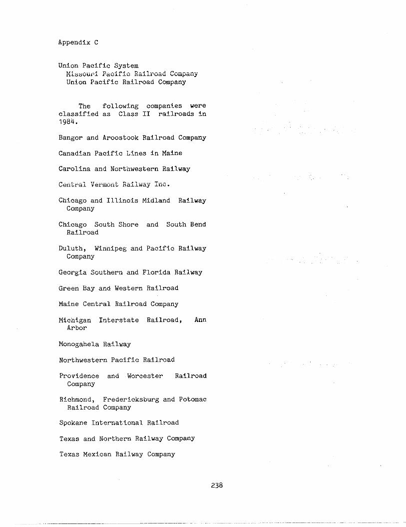
Appendix C
Union Pacific SystemMissouri Pacific Railroad CompanyUnion Pacific RailrOad Company
The following companies wereclassified as Class II railroads inlg84.
Bangor and Aroostook Railroad Company
Canadian Pacific Lines in Maine
Carolina and Northwestern Railway
Central Vermont Railway Inc.
ChicagO and Illinois Midland Ratlway
Company
Chicago South Shore and South BendRailroad
Duluth, Winnipeg and Pacific RailwayCompany
Georgia Southern and Florida Ra!lway
Green Bay and Western Railroad
Maine Central Railroad Company
Michigan Interstate Railroad, AnnArbor
Monogahela Railway
Northwestern Pacific Railroad
Providence and Worcester RailroadCompany
Richmond, Fredericksburg and PotomacRailroad Company
Spokane Internatl.onalRailroad
Texas and Northern Railway Company
Texas Mexican Railway Company
238

MPERDIX D
Emple of a Di~osttc Tasm Cross- Evaluation Report Used by Nel~raska
DIAGNOSTIC TEAM ~..r+,.(>T.0.
CROSSIN8 EVAIUAITION REPORT ‘
:.,!,, ,>, “,. <,.”,,,. ,,, V,!. W:
,. .,..
RAIL* ...: 1?,, .,, ,.”.., ”: ‘c!,”: r,,, ,,, ,,,,,,,
t“”’””””-””””””-““““””” i.,,..,”, s, O.: ~,,,e.ET,”oA.N#ME:
I.,...s, .,., T, M, TA..E, TKT, ON: :6t:.:MTL,ms7, !. . . . . . . . . . . NAME
I,.. .
,N,T,A,ED BY [] ‘AILROAD~:]STATE ~~ LOCAL ➤1 0,H6n~ATE ,N,T,ATEO
,.. INME I A, FIL,AT, OM
I ___ :.?2 . .._ ,..,, .f 3
~’;..1..,,.. ..-.
~~ : .
7
239
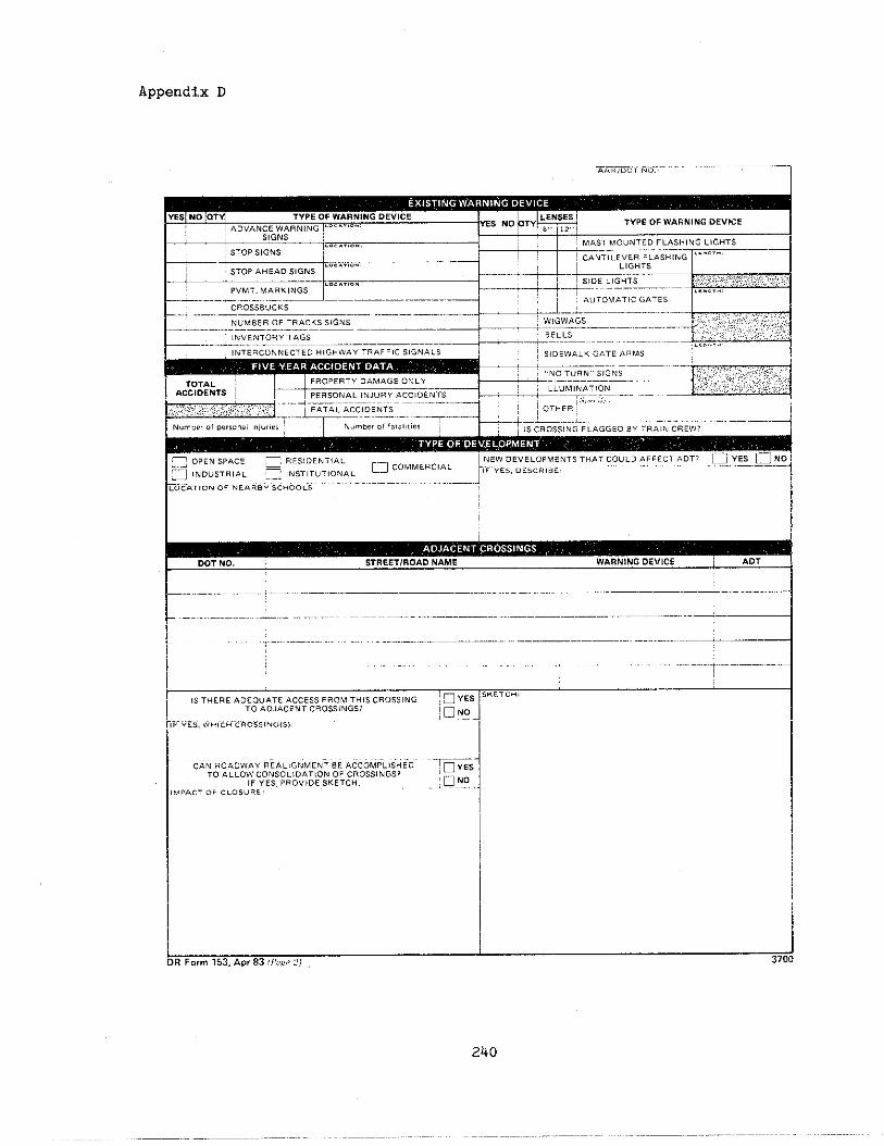
Appendix D
~o,mo.: . . . . . . . . . . . . . . . . . . .
YESI NO [OT~ TYPE OF WARNING DEVICETYPE OF WARNING DEVICE
MA,, .“,,.. s. FI.ASHING LIGHT,
I STOPSIGNS /’-’’.’-”’ I : “”,.,,.,,,..,..u,.,.”l....~-
~ OPEN SPACE ~ RES, DE NT!AL,- ,N,T,,”T,ONAL = cOMMERclAL k~~”ri.=”==-----““’ “’:J”””=”UNNEW .,”,,O,.,., s THA7 COULD AFFECT ADT,
~-1(NDUSTRIAL
r“-””””-”””””-”””-”””””‘-””””---””””.- —
.0,.710. OF .,... ” Sc.oou:’. . ..-
I
1 .,. .0
DOT NO. I STREET/ROADNAME I WARNINGDEVICE I ADT
~... .. ......... ,
CA. ROAOWA, .“i.L,.iMENTBE ACCOMPLIiHLbTO AL LOW CO. SO L, OAT ION OF CROSSINGS?
IF “,,, PRO” IDE SKETCH.IMPACT <>, ..0, ”.:
240
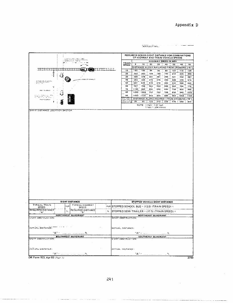
.“., ,,, ,.., “
!,
Appendix D
~-.-....,.,.0,.,,.:
S, G “, D,S,AWE STOPPED VEHICLE SIGHT DISTaNCE
TYPICAL T..,. I f:l:p’~;~Hw:+----------------- :-----------=----–;_FTANt~- -, _EOulR,D ~(,TANcEm,,STOPPED SCHOOL B“s (13 s) ,TBA,N SPEED)
.,A. I ;It STOpPED SEMI .THAILER = (17.5) (TRAIN SPEED] =
NORTHWEST .“.0..., NO.,..,,, 0..0...,.“, ..,,. ”.,, O.: s,.,!, O.s,. ”.,,0.,
,, . . . . .. . . . . . . AC, ”,. O,s, . . . .
.~. . ft. ,,A,,= i,,So”T”w,,, Q“.O. ANT
,.., O.s,. ”.,,0.SO”, ”..*T . . . . . . . .
s!.., OSSTR” CT,..:
,., . . . ., s,...,: AC,... .!s, . . . .
,,K,~ .........17.,x, ,. f,,
R Form 153, APr 83 {,,.,? .,} 3700
2U1

Appendix D
,, ,,s, ,
q
ES No
,-
,..
m
1ARE IMPROVEMENTSTO THE CROSING n
RECOMMENDED? H,,,M,Ro”EMEN-
,. OF IMP...,.
CROSSINGSIGNALS
!LLUMINA, IO”
OT., R
:, ADr 83 ,),,,,. !)
,.,,..
242
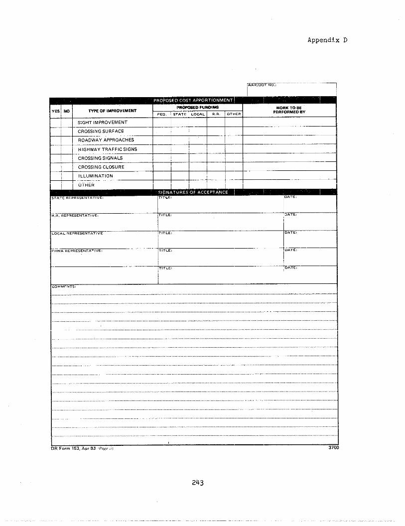
Appendix D
.-*. . ...0. .,
PR-ED FUN08W“Es~No TYPE OF IMPROVEMENTWORK To BE
t ,,0. STAT . Lo.., . .. . O.*E. PERFORMED BY
SIGHT IMPROVEMENT
-+” <G:y;,z.:.,s
HIGHWAY TRAFFIC SIGNS;1
!
——
CROSSING SI{NALS I I
CROSSING CLOSUREI
! ~~
,— ,LL” MI NAT ,ONI
~ OTHER1
I.-*. . .
STATE .EPR.SE. T. T!VE: ,1.,,.: DATE,
243
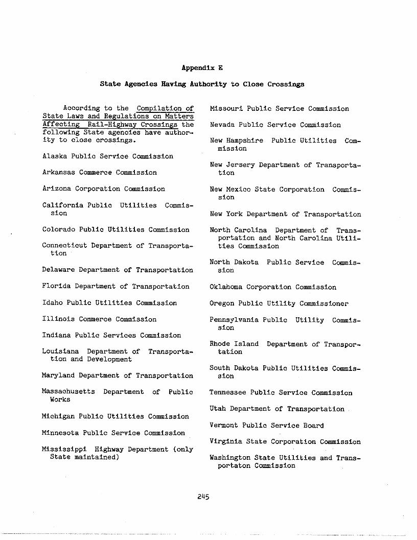
Appendix E
State Agencies SstiW Authority to Close Crossiqs
According to the Compilation ofState Laws and Regulations on MattersAffecting Rail-Highway Crossin@ thefollowing State agencies have :~uthor-ity to ciose cros~ings.
Alaska Public Service Cmission
Arkansas Comerce C~lssion
Arizona Corporation Comission
California Public Utilities Comis-sion
Colorado Public Utilities Comi.ssion
Connecticut Department of Transportat-ion
Delaware Department of Transportation
Florida Department of Transportation
Idaho Public Utilities Comiss~.on
Illinois Comerce Comission
Indiana Public Services Comisslion
Louisiana Department of Transporta-tion and Development
Maryland Department of Transportation
Massachusetts Department of PublicWorks
Michigan Public Utilities Comi,ssion
Minnesota Public Service Comission
Mississippi Highway Department (onlyState mintained )
Missouri Public Service Comission
Nevada Public Service Comission
New Hampshire Public Utilities Com-mission
New Jersery Department of Transporta-tion
New Mexico State Corporation Comis-sion
New York Department of Transportation
North Carolina Department of Trans-portation and North Carolina Utili-ties C~issiOn
North Dakota Public Service Comis-Sion
Oklahma Corporation Comission
Oregon Public Utility C~isstoner
PennsyllTaniaPublic Utility Co~is-sion
Rhode Island Department of Transpor-tation
South Dakota Public Utilities Cowis-sion
Tennessee Public Service Commission
Utah Department of Transportation
Vemont Public Service Board
Virginia State Corporation COmissiOn
Washington State Utillties and Trans-portationC-isslon
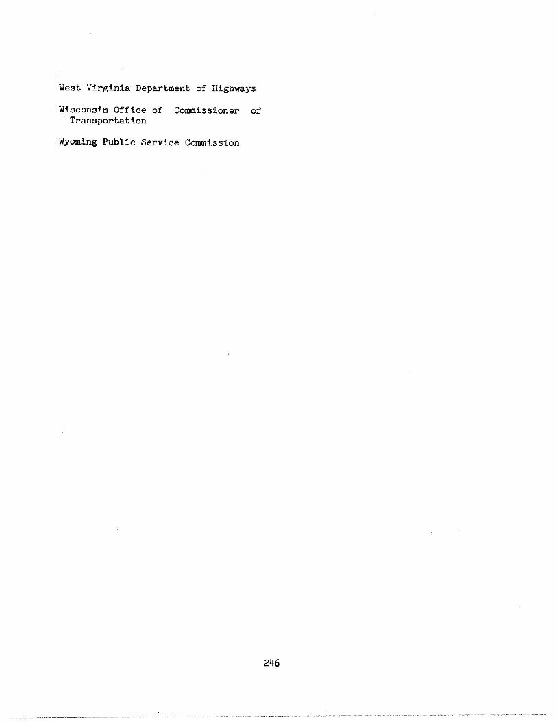
West Virginia Department of Hi/3hways
Wisconsin Office of Commissto]ler ofTransportation
Wyoming Public Service Commission
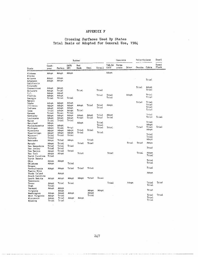
APP~DIX F
Crossing Smfaces Used By StatesTrial Basis or Adopted for General Use, 1984
R“bbe,, Concrete Polyethyl,”e Steel
Good- SkF8 Red FAB-RA Per.. steel
state Park.. DR1 Hawk @“i $tr.il CAST Other Oneida Cobra Plank***.************R***** ******************>,*****************************:EE*** ******"****"**""****************
Adopt AdoPt
Adopt Adopt
Adopt Adopt
.,. —.AOOPt
Trial
Adapt
AdoptAdoPt
Adopt
TrialAdopt
Ad”pt
Trial
Trial
Adopt
AdoptTrial
Adopt
Trial
Trial
Trial
Trial
Trial
Adopt
TrialAdopt Adopt
Adopt Trial
Adopt AdoPt
Adopt Adopt
Trial Trial
TrialTrialTrial
Adopt Trial
Triel
DelawareD.C.
FloridaGeorgia
Hawaii
Idaho
Trial Trial AdoPtTrial
Trial
Trial
AdoptAdoptAdoPtTrialTrialAdaptAdoBtTrialAdoptAdoptAdoPtAdaPtAdoptTrialTrialAdopt
AdoPtAdoPtAdoPtAdoptTrialAdoptAdoptTrial
AdoptTrialAdoptAdoptTrial
Trial
TrialTrialTrial
Trial
Trial AdoptTrial
IllinoisJ.ndi,..1... Trial
K,”,,,Ke”t”ckyLouisia”.
TrialTrial Trial
Trial
Trial AdoptTrial Trial
TrielTrialTrial Trial Trial
Adopt AdoptTrial Trial
&i”,tiryl..dMassa.h”set),s
Adopt
Trial TrialTrial
Trial
Trial Trial
Trial
r,i.1Trial
hd.~rTrial
~d.~tAdoptTrial
Adopt
AdoptTrial TrialAdopt
MichiganPlin”esotaMississippiMissouriMontanaNebraska
TrialTrialTrialAdopt
Adopt
Trial
AdoptTrial
Trial TrialNevadaN.” HampshireNew JerseyN.. Mexic”New YorkNorth CarolinaNorth Dakota
Ohio
Oklahow
AdoptTrialTrialAdoptAdoptTrial
Trial
TrialTrialTrial
Trial
Trial
TrialAdoptAdopt
OregonPen”sylv.nia AdoptPuerto RicoRhode lelandSouth CarolinaSouth Dak”ta AdoptTe”oesseeTexas AdoptUtah T.i.lVermont AdoptVirginiaWashington AdoptWest Virginia AdoptWi.c.”si” Adopt
Wyo.i.g Trial
Trial
Adopt
Adopt
AdoPt
Adopt Adopt Trial
Trial Adopt Trial TrialTrial
Trial
Adopt
AdoPt
AdoPt
AdoptAdoPtTrial
Trial
Trial TrialTrialTrial
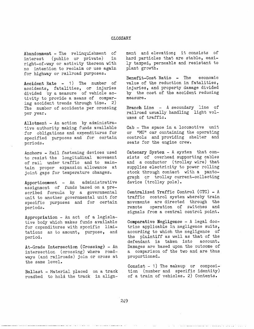
GLOSSARY
Abandonment - The relinquishment ofinterest (public or private) inright-of-way or activity thereon withno intention to reclaim or use againfor highway or railroad purposes.
Accident Rate - 1) The number ofaccidents, fatalities, or injuriesdivided by a measure of vehicle ac-tivity to provide a means of compar-ing accident trends through time. 2)The number of accidents per crossingper year.
Allotment - An action by administra-tive authority making funds availablefor obligations and expenditures forspecified purposes and for certainperiods.
Anchors - Rail fastening devices usedto resist the longitudinal movementof rail under traffic and to main-tain proper expansion allowance atjoint gaps for temperature changes.
Apportionment - An administrativeassignment of funds based on a pre-scribed formula by a governmentalunit to another governmental unit forspecific purposes and for certainperiods.
Appropriation - An act of a legisla-tive body which makes funds availablefor expenditures with specific limi-tations as to amount, purpose, andperiod.
At-Grade Intersection (Crossing) - Anintersection (crossing) where road-ways (and railroads) join or cross atthe same level.
Ballast - Material placedroadbed to hold the track
,,.
on a trackin align-
ment and elevation; it consists ofhard particles that are stable, easi-ly tamped, permeable and resistant toplant growth.
Benefit-Cost Ratio - The economicvalue of the reduction in fatalities,injuries, and property damage dividedby the cost of the accident reducingmeasure.
Branch Line - A secondary line ofrailroad usually handling light vol-umes of traffic.
Cab - The space in a locomotive unitor !t~!!car containing the operating
controls and providing shelter andseats for the engine crew.
Catenary System - A system that con-sists of overhead supporting cablesand a conductor (trolley wire) thatsupplies electricity to power rollingstock through contact with a panto-graph or trolley current-collectingdevice (trolley pole).
Centralized Traffic Control (CTC) - Atraffic control system whereby trainmovements are directed thrm~gh theremote operation of switches andsignals from a central control point.
Comparative Negligence - A legal doc-trine applicable in negligence suits,according to which the negligence ofthe plaintiff as well as that of thedefendant is taken into account.Damages are based upon the outcome ofa comparison of the two and are thusproportioned.
Consist - 1) The makeup or composi-tion (number and specific identity)of a train of vehicles. 2) Contents.
Glossary
Construction - The actual physicalaccomplishment of building, improv-ing, or changing a railroad-highwaygrade crossing or other finite facil-ity.
Contract - The mitten agreement be-tween the contracting agency and thecontractor setting forth the obliga-tions of the parties theremder forthe performance of the prescribedwork. The contract includes the invi-tation for bids, proposal, contractform and contract bond, specifica-tions, supplemental specifications,special provisions, general and de-tailed plans, and notice to proceed.The contract also includes any changeorders and agreements that are re-quired to complete the constructionof the work in an acceptable manner,including authorized extensionsthereof, all of which constitute oneinstrument.
Contractor - The individual, partner-ship, firm corporation, or any ac-ceptable combination thereof, orjoint venture, contracting with anagency for performance of prescribedwork.
Corridor - A strip of land betweentwo termini within which traffic,topography, environment and othercharacteristics are evaluated fortransportation purposes.
Cross Section - A vertical section ofthe gromd and facilities thereon atright angles to the center line.
Crossing Angle - The angle of 90 de-grees or less at which a railroad anda highway intersect.
Crosstie - The wooden or concretesupport upon which track rails restand which holds them to gauge andtransfers their load through theballast to the subgrade.
Culvert - Any structure mder theroadway with a clear opening of twen-ty feet or less measured along the
center of the roadway.
Diagnostic Team - A group of knowl-edgeable representatives of the par-ties of interest in a railroad-high-way crossing or a group of crossings.
Do-Nothing Alternative - An altern?-tive which refers to the existingstate of the system.
Easement - A right to use or controlthe property of another for desig-nated purposes.
Drainage Easement - An easement fordirecting the flow of water.
Planting Easement - An easement forreshaping roadside areas and estab-lishing, maintaining, and control-ling plant growth thereon.
Sight Line Easement - An easementfor maintaining or improving thesight distance.
Slops Easement -cuts or fills.
An easement for
Determination ofEconomic Analysis -the cost-effectiveness of a projectby comparing the benefits derived andthe costs incurred in a project.
Cost/Benefit Analysis - A form ofeconomic evaluation in which inputis measured in terms of dollarcosts and output is measured interms of economic benefit of aproject as compared to the incurredcost of the project.
Cost/Effectiveness Analysis - Acomparison study between the costof an improvement (initial plusmaintenance) and the benefits itprovides. The latter may be de-
250
Glossary
rived from accidents reduced, trav-el time reduced, or increased vol-ume of usage, and translated intoequivalent dollars saved.
Encroachment - Unauthorized use ofhighway or railroad right-of-way oreasements as for signs, fences,buildings, etc.
Equipment Rental Rate - Equipmentusage charges usually established ona time or mileage use basis, includ-ing direct costs, indirect costs anddepreciation.
E~enditures - A term applicable toaccrual accowting, meaning totalcharges incurred, including expenses,provision for retirement of debt, andcapital outlays. The making of a pay-ment is a disbursement.
E~osme Index - A method of meas-~ing the conflict of highway trafficwith train traffic at railroad-high-way grade crossings for the purposeof developing accident rates. Theexposure index is the product ofannual train miles and vehicle milesdivided by 10 to the 18th power forconvenience.
Force Accomt Work - Prescribed workpaid for on the basis of actual costsand appropriate additives.
Fmctional Classification - Divisionof a transportation network intoclasses, or systems, according to thenature of the service they are toprovide.
Grade - The rate of ascent or descentof a roadway, expressed as a percent;the change in roadway elevation perwit of horizontal length.
Grade Separation - A crossing of twohighways, or a highway and a rail-road, at different levels.
Guardrails - Traffic barriers used toshield hazardous areas from errantvehicles.
Highway, Street, or Road - A generalterm denoting a public way for pur-poses of vehicular travel, includingthe entire area within the right-of-way.
Lading - Freight or cargo making up ashipment..
Lane - A strip of roadway used for asingle line of vehicles.
Auxiliary Lane - The portion of theroadway adjoining the through trav-eled way for parking, speed change,turning, storage for turning, weav-ing, truck climbing or for otherpurposes supplementary to throughtraffic movement.
Pullout Lane - An amiliary laneprovided for removal from thethrough traffic lane those vehi-cles required to stop at all rail-road-highway grade crossings.
Speed-Change Lane - An auiliarylane, including tapered areas, pri-marily for the acceleration or de-celeration of vehicles entering orleaving the through traveled way.
Traffic Lane - The portion of thetraveled way for the movement of asingle line of vehicles.
Line Hau~l- The movement of freightover the tracks of a railroad fromone town or city to another tow orcity.
Local Freight Train - A train with anassigned. crew that works betweenpredesignated points. These trainshandle the switching outside thejurisdiction of a yard switcher.
251
Glossary
Locomotive - A self-propelledunit ofon-track equipment designed for mov-ing other rail freight and passengerequipment on rail tracks.
Main Line - The principle line orlines of a railway.
Main Track - A track extendingthrough yards and between stations,upon which trains are operated bytimetable or train order or both, orthe use of which is governed by blocksignals or by centralized trafficcontrol.
Materials - Any substances specifiedfor use in the construction of aproject and its appurtenances.
Measure of Effectiveness (MOE) - Ameasurable unit or set of units as-signed to each evaluation objective.The data collected in the units ofthe MOE will allow for a determina-tion of the degree of achievement forthat objective.
Pavement Makings - Markings set intothe surface of, applied upon, orattached to the pavement for thepurpose of regulating, warning, orguiding traffic.
Pavement Structure - The combinationof subbase, base course, and surfacecourse placed on a subgrade to sup-port the traffic load and distributeit to the roadbed.
Base Course - The layer or layersof specified or selected materialof desigued thickness placed on asubbase or subgrade to support asurface course.
Surface Course - One or more layersof a pavement structure designed toaccommodate the traffic load, thetop layer of which resists skid-
ding, traffic abrasion, and thedisintegrating effects of climate.The top layer sometimes called‘rWearingCourse!f.
Subbase - The layer or layers ofspecified or selected material ofdesigned thickness placed on asubgrade to support a base course.
Subgrade - The top surface of aroadbed upon which the pavementstructure and shoulders includingcurbs are constructed.
Plaintiff - The person who begins anaction at law; the complaining partyin an action.
Plans - The contract drawings whichshow the location, character, anddimensions of the prescribed work,including layouts, profiles, crosssections and other details.
Precedent - An adjudged case or judi-cial decision that furnishes a ruleor model for deciding a subsequentcase that presents the same or simi-lar legal problems.
Preliminary Engineering - The worknecessary to produce constructionplans, specifications,and estimatesto the degree of completeness re-quired for undertaking constructionthereunder, including locating, sur-veying~ designing, and related work.
Rail Joint - A fastening designed tounite abutting ends of rail.
Railroad Line Miles - The aggregatelength of road of linehaul railroads.It excludes yard tracks, sidings, andparallel lines. Jointly-used trackis counted only once.
Railroad Track Miles - Total miles ofrailroad track including multiple
252
Glossary
main tracks, yard tracks and sidings,owed by both line-haul and swi-tchingand terminal companies.
Railroad-Highway Grade Crossing - Thegeneral area where a highway and arailroad cross at the same ;Level,within which are included the rail-roadg roadway, and roadside facili-ties for traffic traversing thatarea.
Pedestrian Crossing - A railroad-highway grade crossing that is usedby pedestrians but not by vehicles.
Private Crossin< - A railroad.-high-way grade crossing that is on aprivately owned roadway utilizedonly by the ower 1s licensees andinvitees.
Public Crossing - A railroad-high-way grade crossing that is on aroadway under the jurisdiction of,and maintained by, a public al~thor-ity and open to the traveling pub-lic.
Right-of-Way - A general term denot-ing land, property, or interesttherein, usually in a strip, acquiredfor or devoted to transportationpurposes.
Roadway - The portion of a highway,including shoulders, for vehicularuse. A divided highway has two ormore roadways.
Salvage Value - Estimated residualworth of program or project compo-nents at the end of their expectedservice lives.
Service Life - The period of time, inyears, in which the components of aprogram or project can be expected toactively affect accident experience.
Shoulder - The portion of the roadwaycontiguous with the traveled way pri-marily for accommodation of stoppedvehicles for emergency use, and forlateral support of base and surfacecourses.
Sidewalk - That portion of the road-way primarily constructed for the useof pedestrians.
Sovereign Immmity - The immunity ofa government from being sued in itsOm courts except with its consent,or other exception.
Statute of Limitations - A statutethat imposes time limits upon theright to sue in certain cases.
Stopping Sight Distance - The lengthof highway required to safsly stop avehicle traveling at a given speed.
Superelevation Rate - The rate ofrise in cross section of the finishedsurface of a roadway on a curve~measured from the lowest or insideedge to the highest or outsids edge.
Tie Plate - A flanged plate between arail and a crosstie that distributesthe rail load over a larger 2rea andhelps hold track gauge.
Timetable - 1) The authority for tinemovement of regular trains subject tothe rules; it contains classifiedschedules with special instructionsrelating to the movement of trainsand engines. 2) A listing of thetimes at which vehicles are due atspecified time points (colloquial).
Tort - Any private or civil wrong byact or omission, but not includingbreach of contract. Some torts mayalso be crimes.
253
Glossary
Track - 1) An asssmblyties, and fastenings over
of railsswhich cars,
locomotives and tr~ins are moved. 2jthe width of a whesled vehicle fromwheel to whsel and usually from theoutside of the rims.
Double or Multiple - Two or moremain tracks over which trains maytravel in both directions.
-- I) The main track on aroadbed having one main track uponwhich trains are operated in bothdirections. 2) In multiple trackterritory, the process of runningall trains, regardless of directionon one track while the othertrack(s) is (are) temporarily out
of service.
Track Gauge - The distance betweenthe inside face of the heads of thetwo rails of a track measured perpen-dicular to the center line. (Standardguage in U.S. is 4’-8.5”.)
Traffic Control Device - A sign, sig-nal, marking or other device placedon or adjscent to a street or highwayby authority of a public body orofficial having jurisdiction to regu-late, warn, or guide traffic.
Active Traffic Control Device –Those traffic control devices acti-vated by the approach or presenceof a train, such as flashing lightsignals, automatic gates and simi-lar devices, as well as manuallyoperated devices and crossingwatchmen, all of which display tomotorists positive warning of theapprOach or presence of a train.
Passive Traffic Control Device -Those types of traffic controldevices, including signs, markingsand other devices, located at or inadvance of grade crossings to indi-
cate the presence of a crossingwhich do not change aspect uponapproach or presence of a train.
butthe
Traffic Control Signal - Any devicewhether manually, electrically, ormechanically operated by whichtraffic is alternately directed tostop or permitted to proceed.
Traffic Markings - All lines, pat-terns, words, colors, or otherdevices, except signs, set into thesurface of, applied upon, or at-tached to the pavement or curbingor to the”objects within or adja-cent to the roadway, officiallyplaced for the purpose of regula-ting, warning, or guiding traffic,.
Traffic Operation Plan - A program ofaction designed to improve the utili-zation of a highway, a street, orhighway and street network, throughthe application of the principles oftraffic engineering.
Traffic Sign - A device momted on afixed or portable support whereby aspecific message is conveyed by meansof words or symbols, officiallyerected for the purpose of regula-ting, warning, or guiding traffic.
Traffic Si~al - A power-operatedtraffic control device by which traf-fic is regulated, warned, or altern-ately directed to take specific ac-tions.
Cycle Time - The time required forone complete sequence of signalindications.
Detectors - Mechanical or electron-ic devices that sense and signalthe presence or passage of vehicu-lar or railroad traffic at one ormore points in the roadway ortrack.
254

Glossary
Phase - Those right-of-way andclearance intervals in a cycle as-signsd to any independent move-ment(s) of vehicular traffic.
Train - 1) One or more locomotivewits with or without connected.cars.2) Two or more vehicles physicallyconnected and operated as a unit.
Through - A freight train operatingbetween major classificationsyardsand serving non-local traffic.
Unit - A freight train moving greattomage of single bulk productsbetween two points coupled \rith asystem of efficient, rapid loadingand unloading facilities.
Train Orders - Authorization to movea train as given by a train dispatch-er either in writing or verbally.
Traveled Way - The portion of theroadway for the movement of vek[icles,exclusive of shoulders.
Vehicle - A means of carrying ortransporting something.
Bicycle - A vehicle having tkrotan-dem wheels, propelled solely byhuman power, upon which any personor persons may ride.
Bus - A self-propelled rubber-tired=icle designed to accommodate 15or more passengers and to operateon streets and roads.
Design Vehicle - A selected motorvehicle, the weight, dimensions andoperating characteristics of whichare used in highway design.
Motorcycle - A two-wheeled motor-ized vehicle having one or twosaddles and sometimes a sidecarwith a third supporting wheel.
Passenger Car - A motor vehicle,except motorcycles, designed forcarrying 10 passengers or less andused for the transportation ofpersons.
Semi-trailer - A vehicle with orwithout motive power, designed forcarrying persons or property andfor being dram by a motor vehicleand so constructed that some partof its weight and that of its loadrests upon or is carried by anothervehic:Le.
Special Vehicle - A vehicle whosedriver is required by law to stopin advance cf all railroad-highwaygrade crossings. Typically, spe-cial vehicles include: vehiclestransporting passengers for hire;trucks carrying hazardous mate-rials; and school buses.
Truck Tractor - A motor vehicledesigned for drawing other vehiclesbut not for a load other than apart of the weight of the vehicleand load dram.
Volume - The number of vehicles pass-ing a given point during a specifiedperiod of time.
Average Daily Traffic - The average24-hour volume, being the totalvolume during a stated period di-vided by the number of days in thatperiod. Unless otherwise stated,the period is a year. The term iscommonly abbreviated as ADT.
Design Volume - A volume determinedfor use in design, representingtraffic expected ~o”use ~he high:way. Unless otherwise stated, itis an hourly volume.
Warrants - The minimum conditionswhich would justify the establishment
Glossary
of a particular traffic control regu-lation or device, usually includingsuch items as traffic volumes, geo-metric, traffic characteristics,accident experience, etc.
Y~d - A system of tracks withindefined limits that is provided formaking up trains, storing cars, andother purposes.

INDEX
Abandonment: bl, 89, 94-96, 166-167,216, 249
Accident Prediction Formulae: 38, 63,66-?8, 8?, 1?7-180, 228-230
Accidents: 3-8, 14-16, 18-19, 27-28,34, 36-40, 42-43, 45-46, 48-52, 56-62-78, 84, 87, 89-90, 101, 104,107, 109, 126, 140, 143-144, 165,167-169, 171-181, 206, 209-214,217, 219, 221, 223, 226-228, 231,249, 251, 253, 256
Accident Costs: 171-176
Active Advance Warning Signs: 81, 83,103, 114-115, 169, 227-228
Active Traffic Control Devices: 7,11-13, 21, 29, 33, 43, 48, 66-72,77-78, 80, 84-86, 89, 93, 96, 99,101-125, 141-143, 768, ‘177-179,
183-186, 189, 191, 205, 213-215,217-218, 226-230, 233, 235, 254
Advance Warning Signs: 12, 29, 31,80-81, 83, 94, 96-103, 114-115,186, 194, 209, 212, 219-220, 226-227
Advisory Speed Plates: 97, 100
Agreements: 13, 42, 86-87, 95-96,183, 186-189, 207, 213, 250
American Association of State High-way and Transportation Officials:19, 21, 35, 50, 88, 138, 168-169,185, 223
American Railway Engineering Associa-tion: 14, 19, 21, 25, 136, 168, 231
American Road and TransportationBuilders Association: 199 22
American Short Line Railroadtion: 19, 21, 216, 223
Associa-
American Trucking Association: 19,22, 223
Annual Average Daily Traffic: 36-39,51-52, 54, 66-?2, 77, 79, 84, 93,98, 165-166, 180, 255
Approach Zones: 31, 80, 82-83
Association of American Railroads:13-15, 19, 2a, 50, 185, 207-208,221, 223, 231, 235
Audible Traffic Control Devices: 31,43, 110
Automatic Gates: 12, 29-31, 66-72,,78, 92, 94, 96, 98, 102-104, 107,116, 125, 143, 169, 173, 177-?79,,181, 184, 207, 214, 217, 224, 226,228, 230, 235, 254
Ballast: 47, 127, 130-131, 136-138,143-145, 147-150, 159, 164.,249-250
Barricades: 94, 194, 198-199, 201-202
Benefit-COst Analysis: 43, 91, 173,,175-177, 211, 249-250
Bicycles: 4, 56, 63, 78, 85, 110,213, 218-220, 255
Blocked142
Bridgement:
Bureau61-62
Crossings: a, 14, 42, 140,
Rehabilitation and Replace-.12, 184-185
Of MOtor Carrier Safety: 56,
257
Index
Buses: L, 34-36, 38, 56, 63, 66, 78,84-85, 90, 95, 109, 116, 139, 143,214, 218-219, 255
Cantilevered Flashing Lights: 39,103, 105-107, 110, 113-115, 207
Channelizing Devices: 193-199
Closure: 11, 13, 54, 84-a7, 89-94,136, 140, 142, 166, 181, 183-184,191-192, 194-196, 233, 245-246
Commmity Relations: 1-2, 13, 41-42,85-86, 91-93, 142, 225
COst-EffectivenessAnalysis: 172-175,177, 211, 228, 250
Cross Sections: 84, 135, 137-140,150, 153-164, 250, 252-253
Crossbucks: 12, 29-30, 33, 52, 66,69, 94, 96-lo2, 106, 184, 205,215, 22a, 233, 235
Crossties: 47, 137, 143, 145,151, 153-165, 250, 253-254
Delineators: 143, 193, 196, 198
Diagnostic Teams: 78-84, 86,179, 239-243, 250
DO Not Stop on Tracks Signs: 97,106, 205
Drainage: 39, 47, 84, 92-93,136-139, 143-145, 147-150,~64, 205, 250
Driver Characteristics: 29-33,80-83, 90, 126, 131-134, 168;223, 226-227
Miver Education: 10, 12, 15,212, 217-218, 221, 223-225
Driver Enforcement: 13, 19, 40,212, 218, 221, 223-225
214-
147-
177,
101,
110,153,
41,211,
40,
135,
Economic Analysis: 43, 93, 171-1al,250
Elimination: 2, 9-12, 15, a6, 89-96,166, 183-1a4
Engineering Studies: 51, 55, 79-85,87-88, 93, 9a-102, 107, 115, 135,140, 143, 167, 175, 211, 221
Evaluation: 26, 51, 79-85, 166-167,171-181, 209-212, 215, 224-225,227, 231, 239-243, 250, 252
Exempt Crossing/Signs: 96-97, 101,205
Exposure Index:106, 109, 251
Federal Highway12-13, 16-19,
3-5, 7, 70-72, 91,
Administration: 10,28, 50-52, 56, 79,
a5, 87-a9, 116, 141, 168-169, 181,184-la5, 187-188, 190-191, 203,20a-209, 212, 221, 225-229, 233
Federal Railroad Administration: 4,10, 12, 17-18, 27-2a, 43, 45, 49-50, 52, 54-57, 87-8a, 95, 148, 16a-169, 181, 221, 226-230
Flagging: 30-31, 78, 96, 98, 131,142, 193-195, 198-203, 214, 254
Flangeway: 144, 148, 150, 152-165,219
Flashing Lights: 12, 29-30, 52, 66-72, 92, 94, 96, 102-116, 123, 125-126, 169, 173, 177-179, Ial, 184,206-207, 214, 224, 228, 235, 254
Freight Cars: 41-45, 47-48, 125, 254-256
Freight Car Reflectors: U, 50, 230
Finding: 7-11, 13, 15-18, 27, 41, 85-87, 91, 92, 171, 175, 177-178, 183-187-la8, 190-191, 206-207, 213,215-216, 233, 235, 249
258
Index
Gate (see Automatic Gate)
GeOmetrics: 35-36, 38, 78, 83, 87-88,98, 100, 115-116, 131, 135-140,143, 169, 192-193, 217, 226, 256
Grade Separations: 1, 3, 7, 9, 11-12,15, 17, 40, 52, 86, 89-93, 166-167,183-185, 217, 220, 230-231, 233,251
Hazard Zones: 31-33
Hazardous Materials: 7, 19, 33, 36,56, 63, 6b , 68, 78-79, 84-85, 87-90, 92, 95, 109, 116, 139, 143,180, 218-219, 221, 228, 231, 255
High Speed Railroads: 9, 85, 91, 109,126, 141-142, 180, 213, 217-218,229
Highway Relocation: 11, 90-92, 183-184
Highway Safety Improvement Program:10, 17, 28, 51, 171-172, 181, 209
Horizontal Alignment: 3b, 38-39, bb,68, %1, 84, 134-136, 138, 140, lb7
Illumination: 11, 3b, 40, 84, 97-98,131, 140-141, lb8-lb9, 177, 183-184, 205, 212
Improvement Costs: 9-12, 15-17, 33,51, 5b, 63, 87, 89-91, 140, 165-167, 171-180, 183-190, 205, 228,250
Information Handling Zones: 31-33
Institute of Transportation Engi-neers: 19, 22-23
Insurance: 27, 171, 187, 190-191
Interstate Commerce Commission: 9,lb, 28, 40, 43, 95, 172, 215-21b,237
Islands, Traffic: 143, 1b9
Liabili-by: 14-lb, 23-27, 190-191,227, 230
Locomotives: 42-45, 50, 125, 229-230,249, 252, 254-255
~intenance: 3, 9, 12-13, 15, 17-18,21-23, 27-28, 33, 39, 47, 86, 90-91, 93, 96, 107, 135-137, 143-144,149, 153-156, 159, Ibl, 165, 171-17b, 178-181, 185-187, 191-194,19b, 200, 20b-208, 213, 21b, 220,235, 250, 253
Materials Transportation Bureau: 5b ,b3-65
Motorcycles: 4, 33-34, 5b, 213-2~4,218-220, 255
National Highway Traffic SafetyAdminj.stration: 17-18, 56, 59-bO,171, 175, 209
National Safety Comeil: 13-15, 19,21-22, 171, 175, 223, 23I
National Transportation Safety Board:14, 17, 19, 3b, 88, 168, 218, 221,223, 231
Nearby Highway Intersections: 3b-37,40, 66, 80-81, 94, 99-loo, 102,107, 115-125, 135, 139, 181, 183,205, 218
Net Amual Benefit: 175-177
Nonrecovery Zones: 31-32, 82
Operation Lifesaver: 12-13, 19, 21-22, 217-218, 223-225, 231
Passive Traffic Control Devices: 29,33, 66-72, 78, 80, 84, 87, 89, 90,94, 9b-lo4, 134, 137, 141-142, 177,181, 183-184, 186, 2ob, 213-214,217-220, 226-229, 233, 235, 254
259
Index
Pavement Markings: 10-12, 29, 31, 80, Roadway Miles: 2-3, 10, 1583-84, 94, 56, 101-103, 169,”186;193-194, 196-198, 200, 206, 220,252, 254
Pedestrians: 3-4,85, 96-97, 107,192-193, 196,221, 225, 253
29, 40, 56, 63, 78,110, 125, 142, 148,213-214, 218, 220-
Preemption of Highway Traffic Sig-nals: 40, 66, 80-81, 94, 102,115-125, 181, 183, 205
?riority (Hazard) Index/Schedule: 55,63-69, 78-?9, 8?, 91, 106, 109,171, 185, 217, 226
Private Crossings: 3, 7, 10, 19, 52,86, 95, 213-215, 217, 225, 253
Public Crossings: 3-5, 7, 9-11, 14-15, 19, 29-30, 33-34, 37-40, 43,45-&6, L8-49, 52, 63, 85-86, 95,140, 144, 166, 181, 213, 215, 225,253
P~llOut Lanes: 38-39, 139-140, 219,229, 251
Raiiroad Line Miles: 1-3, 252
Railroad Relocation: 11, 86, 89, 90-92, 183-185
Railroad Track Miles: 1-2, 15, 252
Railroad Train Miles: 1-3, 41, 251
Railway Progress Institute: 14, 19,21, 169, 223
Research: 10, 13-14, 18, 21-22, 55,226-231
Resource Allocation Procedure: 88,1?7-181, 227-229
Roadway Functional Classification:3, 36, 66, 68, 71-?2, 165, 251
Safety142,
School68,139,255
Barriers: 109-110, 131, 141-168, 196, 198-199, 220, 251
Buses: 7, 33-34, 36, 63, 66,?8, 84, 89-90, 95, 109, 116,143, 180, 214, 218-219, 224,
Short Line Railroads: 41, 95, 213,215-217, 221
Sight Distance: 13, 31, 33, 35-39,56, 66, 68-69, 77-78, 80-84, 97-98,100-101, 107, 109, 126, 131-136,141, 180-181, 206, 212, 217, 219,233, 250, 253
Solar Energy: 125
Special Vehicles: 7, 36, 85-86, 89-90, 95-96, 139, 165, 213, 218-221,229, 255
Stabilization Fabrics: 84, 139, 147,150
Stop Ahead Signs: 97
Stop Signs: 30, 40, 97, 100-101, 214-215
Stopping Distances: 31, 33, 35, 44,77, 82, 107, 115, 131, 140-141,211, 217, 219, 253
Surfaces: 11-14, 36, 39, 66, 68, 81,84, 86, 89-90, 94, 126, 136-137,?43-166, 168-169, 177, 181, 183-184, 186, 188, 191, 194, 205-207,216, 219, 226, 231, 233, 235, 2L7
Systems (Corridor) Approach: 51, 79,85-87, 93, 115, 190, 217, 250
Track characteristics: 39, 41, 43,;;~~;56125-138, 147-165, 250, 252-
Inde>:
Tr;fl;; co;~ol Devices: 7, 9,, 11-15, Wigwags: 30, 66, 104, 21423, 27-31, 33, 41, 43,
48, ;0, ;2, 66-72, 77-81, 84-85, Work Zones: 191-20287-90, 93-94, 95-125, 134, 137,139-143, 166, 168-169, 172, I?7-180, 183-184, 186-189, 191-193,196-203, 205-208, 213-221, 223-224,226-230, 233, 235, 254, 256
Train Characteristics: 41-45, 125-134, 223, 249, 251-255
Train Detection Circuits: 12, 18, 21,36, 48, 84-86, 102-104, 114-116,124-131, 149, 157, 159, 177, 181,183, 189, 205, 217, 227-229
Train HOrn/~istle: 43
Transportation Research Board: 14,19, 22, 230-231
Trespassers: 40, 215, 221, 225
Trucks: 4, 7, 22, 33-36, 38-39, 56,66, 84-85, 88-89, 93-94, 109, 116,133, 136, 142, 168, 180, 214, 218-219, 221, 224, 231, 251, 255
Turn Prohibition Signs: 102, 123
uniform Vehicle Code: 30-31, 50, 169
Us. DOT/AAR National Rail-HighwayCrossing Inventory: 10, 18, 29, 40,48, 50, 52-56, 70, 88, 95, 104,144, 168, 206, 213
Vehicle Characteristics: 29, 33-36,39, 80, 82, 132-134, 137, 219, 255
Vehicle Miles: 2-3, 34, 251
vertical Alignment: 36, 38-39, 66,81, 84, 135-137, 140, 167, 219
Warning Bells: 30, 67, 103, 110, 114,214
Warning Time: 14, 27, 31, 108-109,116, 125-131, 133, 168, 217-219
261*U.S. ~- ?RI- OFFICE: 1998-,38-203,90053