implementing high availability and disaster recovery
TRANSCRIPT

Redpaper
Front cover
Implementing High Availability and Disaster Recovery Solutions with SAP HANA on IBM Power Systems
Dino Quintero
Luis Bolinches
Rodrigo Ceron Ferreira de Castro
Fabio Martins
John Wright


International Technical Support Organization
Implementing High Availability and Disaster Recovery Solutions with SAP HANA on IBM Power Systems
October 2017
REDP-5443-00

© Copyright International Business Machines Corporation 2017. All rights reserved.Note to U.S. Government Users Restricted Rights -- Use, duplication or disclosure restricted by GSA ADP ScheduleContract with IBM Corp.
First Edition (October 2017)
This edition applies to:SAP HANA V2.0 SPS01 revision 10 (2.00.010.00.1491294693)SUSE Linux Enterprise Server for SAP Applications V12 SP2IBM Virtual I/O Server (VIOS): V2.2.4.23IBM Hardware Management Console (HMC): V8.8.6.0 SP1 + MH01703IBM Spectrum Scale V4.2.3.1
Note: Before using this information and the product it supports, read the information in “Notices” on page vii.

Contents
Notices . . . . . . . . . . . . . . . . . . . . . . . . . . . . . . . . . . . . . . . . . . . . . . . . . . . . . . . . . . . . . . . . . viiTrademarks . . . . . . . . . . . . . . . . . . . . . . . . . . . . . . . . . . . . . . . . . . . . . . . . . . . . . . . . . . . . . viii
Preface . . . . . . . . . . . . . . . . . . . . . . . . . . . . . . . . . . . . . . . . . . . . . . . . . . . . . . . . . . . . . . . . . ixAuthors. . . . . . . . . . . . . . . . . . . . . . . . . . . . . . . . . . . . . . . . . . . . . . . . . . . . . . . . . . . . . . . . . . ixNow you can become a published author, too! . . . . . . . . . . . . . . . . . . . . . . . . . . . . . . . . . . . xiComments welcome. . . . . . . . . . . . . . . . . . . . . . . . . . . . . . . . . . . . . . . . . . . . . . . . . . . . . . . . xiStay connected to IBM Redbooks . . . . . . . . . . . . . . . . . . . . . . . . . . . . . . . . . . . . . . . . . . . . . xi
Chapter 1. Introduction. . . . . . . . . . . . . . . . . . . . . . . . . . . . . . . . . . . . . . . . . . . . . . . . . . . . 11.1 About this publication . . . . . . . . . . . . . . . . . . . . . . . . . . . . . . . . . . . . . . . . . . . . . . . . . . . 21.2 The SAP HANA platform. . . . . . . . . . . . . . . . . . . . . . . . . . . . . . . . . . . . . . . . . . . . . . . . . 21.3 High availability for HANA . . . . . . . . . . . . . . . . . . . . . . . . . . . . . . . . . . . . . . . . . . . . . . . . 3
1.3.1 Disaster recovery: SAP HANA Systems Replication . . . . . . . . . . . . . . . . . . . . . . . 51.3.2 High availability: SAP HANA Host Auto-Failover . . . . . . . . . . . . . . . . . . . . . . . . . . 61.3.3 High availability: SAP HANA Systems Replication with SUSE Linux High Availability
Extension . . . . . . . . . . . . . . . . . . . . . . . . . . . . . . . . . . . . . . . . . . . . . . . . . . . . . . . . 8
Chapter 2. Planning your installation . . . . . . . . . . . . . . . . . . . . . . . . . . . . . . . . . . . . . . . 112.1 SAP requirements for HANA on Power Systems implementations. . . . . . . . . . . . . . . . 12
2.1.1 SAP HANA on Power Systems allowed hardware, core, and memory limits and core-to-memory ratios. . . . . . . . . . . . . . . . . . . . . . . . . . . . . . . . . . . . . . . . . . . . . . 12
2.1.2 Supported POWER8 processor configuration. . . . . . . . . . . . . . . . . . . . . . . . . . . . 132.1.3 Supported operating systems . . . . . . . . . . . . . . . . . . . . . . . . . . . . . . . . . . . . . . . . 142.1.4 Operating system customization . . . . . . . . . . . . . . . . . . . . . . . . . . . . . . . . . . . . . . 152.1.5 Multiple production LPAR support on a single POWER8 server. . . . . . . . . . . . . . 152.1.6 Storage and file system requirements. . . . . . . . . . . . . . . . . . . . . . . . . . . . . . . . . . 15
2.2 Preparing your software . . . . . . . . . . . . . . . . . . . . . . . . . . . . . . . . . . . . . . . . . . . . . . . . 182.2.1 Getting your operating system image . . . . . . . . . . . . . . . . . . . . . . . . . . . . . . . . . . 182.2.2 Getting the IBM service and productivity tools for Linux on POWER . . . . . . . . . . 182.2.3 Getting the HANA on Power Systems installation files . . . . . . . . . . . . . . . . . . . . . 19
2.3 SAP HANA implementation scenarios . . . . . . . . . . . . . . . . . . . . . . . . . . . . . . . . . . . . . 192.3.1 Scale-up scenarios without high availability . . . . . . . . . . . . . . . . . . . . . . . . . . . . . 202.3.2 Scale-up scenario with SAP HANA Systems Replication . . . . . . . . . . . . . . . . . . . 202.3.3 Scale-up scenario with SUSE HA and HANA Systems Replication . . . . . . . . . . . 202.3.4 Scale-out scenario with Host Auto-failover . . . . . . . . . . . . . . . . . . . . . . . . . . . . . . 212.3.5 Summary of covered scenarios and reading suggestion . . . . . . . . . . . . . . . . . . . 21
Chapter 3. IBM PowerVM and SAP HANA . . . . . . . . . . . . . . . . . . . . . . . . . . . . . . . . . . . . 233.1 Introduction to PowerVM and SAP HANA. . . . . . . . . . . . . . . . . . . . . . . . . . . . . . . . . . . 243.2 Virtual I/O Server. . . . . . . . . . . . . . . . . . . . . . . . . . . . . . . . . . . . . . . . . . . . . . . . . . . . . . 243.3 Dynamic Placement Optimizer . . . . . . . . . . . . . . . . . . . . . . . . . . . . . . . . . . . . . . . . . . . 27
Chapter 4. SUSE Linux Enterprise Server for SAP Applications V12 SP2 installation and customization . . . . . . . . . . . . . . . . . . . . . . . . . . . . . . . . . . . . . . . . . . . . . . . . . 29
4.1 Introduction . . . . . . . . . . . . . . . . . . . . . . . . . . . . . . . . . . . . . . . . . . . . . . . . . . . . . . . . . . 304.2 Creating the LPAR for SAP HANA . . . . . . . . . . . . . . . . . . . . . . . . . . . . . . . . . . . . . . . . 304.3 Installing the BOS into the LPAR . . . . . . . . . . . . . . . . . . . . . . . . . . . . . . . . . . . . . . . . . 30
4.3.1 Starting the LPAR in SMS mode. . . . . . . . . . . . . . . . . . . . . . . . . . . . . . . . . . . . . . 31
© Copyright IBM Corp. 2017. All rights reserved. iii

4.3.2 Installing BOS from the HMC virtual serial terminal . . . . . . . . . . . . . . . . . . . . . . . 344.3.3 Installing SUSE by using YaST2 and VNC . . . . . . . . . . . . . . . . . . . . . . . . . . . . . . 424.3.4 Installing the service and productivity tools from IBM for Power Systems . . . . . . 604.3.5 Network tuning . . . . . . . . . . . . . . . . . . . . . . . . . . . . . . . . . . . . . . . . . . . . . . . . . . . 624.3.6 Configuring the NTP client . . . . . . . . . . . . . . . . . . . . . . . . . . . . . . . . . . . . . . . . . . 62
Chapter 5. Storage and file systems setup and customization . . . . . . . . . . . . . . . . . . 655.1 Storage layout . . . . . . . . . . . . . . . . . . . . . . . . . . . . . . . . . . . . . . . . . . . . . . . . . . . . . . . . 66
5.1.1 HANA shared area storage layout for scale-up systems . . . . . . . . . . . . . . . . . . . 665.1.2 HANA shared area storage layout for scale-out systems . . . . . . . . . . . . . . . . . . . 665.1.3 Probing for newly attached disks . . . . . . . . . . . . . . . . . . . . . . . . . . . . . . . . . . . . . 68
5.2 Linux multipath setup . . . . . . . . . . . . . . . . . . . . . . . . . . . . . . . . . . . . . . . . . . . . . . . . . . 705.2.1 Applying changes to the multipath configuration. . . . . . . . . . . . . . . . . . . . . . . . . . 73
5.3 File system creation and setup . . . . . . . . . . . . . . . . . . . . . . . . . . . . . . . . . . . . . . . . . . . 755.3.1 File systems for scale-up systems . . . . . . . . . . . . . . . . . . . . . . . . . . . . . . . . . . . . 755.3.2 File systems for scale-out systems . . . . . . . . . . . . . . . . . . . . . . . . . . . . . . . . . . . . 80
5.4 Additional Linux I/O subsystem tuning . . . . . . . . . . . . . . . . . . . . . . . . . . . . . . . . . . . . . 845.4.1 I/O device tuning . . . . . . . . . . . . . . . . . . . . . . . . . . . . . . . . . . . . . . . . . . . . . . . . . . 845.4.2 I/O scheduler tuning . . . . . . . . . . . . . . . . . . . . . . . . . . . . . . . . . . . . . . . . . . . . . . . 84
Chapter 6. System evaluation . . . . . . . . . . . . . . . . . . . . . . . . . . . . . . . . . . . . . . . . . . . . . 876.1 HWCCT overview . . . . . . . . . . . . . . . . . . . . . . . . . . . . . . . . . . . . . . . . . . . . . . . . . . . . . 88
6.1.1 General prerequisites . . . . . . . . . . . . . . . . . . . . . . . . . . . . . . . . . . . . . . . . . . . . . . 886.1.2 SAP Notes . . . . . . . . . . . . . . . . . . . . . . . . . . . . . . . . . . . . . . . . . . . . . . . . . . . . . . 886.1.3 Current key performance indicators values. . . . . . . . . . . . . . . . . . . . . . . . . . . . . . 89
6.2 Tool downloads . . . . . . . . . . . . . . . . . . . . . . . . . . . . . . . . . . . . . . . . . . . . . . . . . . . . . . . 896.2.1 SAPCAR . . . . . . . . . . . . . . . . . . . . . . . . . . . . . . . . . . . . . . . . . . . . . . . . . . . . . . . . 896.2.2 HWCCT.SAR . . . . . . . . . . . . . . . . . . . . . . . . . . . . . . . . . . . . . . . . . . . . . . . . . . . . 906.2.3 Python scripts . . . . . . . . . . . . . . . . . . . . . . . . . . . . . . . . . . . . . . . . . . . . . . . . . . . . 926.2.4 Configuration file templates . . . . . . . . . . . . . . . . . . . . . . . . . . . . . . . . . . . . . . . . . 92
6.3 Scale-up evaluation. . . . . . . . . . . . . . . . . . . . . . . . . . . . . . . . . . . . . . . . . . . . . . . . . . . . 936.3.1 Landscape test . . . . . . . . . . . . . . . . . . . . . . . . . . . . . . . . . . . . . . . . . . . . . . . . . . . 946.3.2 File system test . . . . . . . . . . . . . . . . . . . . . . . . . . . . . . . . . . . . . . . . . . . . . . . . . . . 96
6.4 Scale-out evaluation . . . . . . . . . . . . . . . . . . . . . . . . . . . . . . . . . . . . . . . . . . . . . . . . . . 1046.4.1 Landscape test . . . . . . . . . . . . . . . . . . . . . . . . . . . . . . . . . . . . . . . . . . . . . . . . . . 1046.4.2 File system test (XFS). . . . . . . . . . . . . . . . . . . . . . . . . . . . . . . . . . . . . . . . . . . . . 1066.4.3 File system test (IBM Spectrum Scale) . . . . . . . . . . . . . . . . . . . . . . . . . . . . . . . . 1096.4.4 Network test . . . . . . . . . . . . . . . . . . . . . . . . . . . . . . . . . . . . . . . . . . . . . . . . . . . . 111
6.5 Further reading . . . . . . . . . . . . . . . . . . . . . . . . . . . . . . . . . . . . . . . . . . . . . . . . . . . . . . 113
Chapter 7. SAP HANA software stack installation for a scale-up scenario . . . . . . . . 1157.1 SAP HANA installation overview. . . . . . . . . . . . . . . . . . . . . . . . . . . . . . . . . . . . . . . . . 1167.2 Installation methods . . . . . . . . . . . . . . . . . . . . . . . . . . . . . . . . . . . . . . . . . . . . . . . . . . 117
7.2.1 GUI installation . . . . . . . . . . . . . . . . . . . . . . . . . . . . . . . . . . . . . . . . . . . . . . . . . . 1187.2.2 Text-mode installation. . . . . . . . . . . . . . . . . . . . . . . . . . . . . . . . . . . . . . . . . . . . . 131
7.3 Postinstallation notes . . . . . . . . . . . . . . . . . . . . . . . . . . . . . . . . . . . . . . . . . . . . . . . . . 135
Chapter 8. SAP HANA software stack installation for a scale-out scenario . . . . . . . 1398.1 Differences between a scale-out and scale-up installations . . . . . . . . . . . . . . . . . . . . 140
8.1.1 Prerequisites . . . . . . . . . . . . . . . . . . . . . . . . . . . . . . . . . . . . . . . . . . . . . . . . . . . . 1408.2 Installing HANA scale-out clusters . . . . . . . . . . . . . . . . . . . . . . . . . . . . . . . . . . . . . . . 140
8.2.1 Scale-out graphical installation . . . . . . . . . . . . . . . . . . . . . . . . . . . . . . . . . . . . . . 1418.2.2 Scale-out text-mode installation . . . . . . . . . . . . . . . . . . . . . . . . . . . . . . . . . . . . . 1428.2.3 Storage Connector API setup . . . . . . . . . . . . . . . . . . . . . . . . . . . . . . . . . . . . . . . 146
iv Implementing High Availability and Disaster Recovery Solutions with SAP HANA on IBM Power Systems

8.3 Postinstallation notes . . . . . . . . . . . . . . . . . . . . . . . . . . . . . . . . . . . . . . . . . . . . . . . . . 147
Chapter 9. SAP HANA Systems Replication for high availability and disaster recovery scenarios . . . . . . . . . . . . . . . . . . . . . . . . . . . . . . . . . . . . . . . . . . . . . . . . . . . . 149
9.1 SAP HANA Systems Replication overview . . . . . . . . . . . . . . . . . . . . . . . . . . . . . . . . . 1509.1.1 SAP HANA System Replication methods . . . . . . . . . . . . . . . . . . . . . . . . . . . . . . 1519.1.2 HSR requirements . . . . . . . . . . . . . . . . . . . . . . . . . . . . . . . . . . . . . . . . . . . . . . . 152
9.2 Implementing HSR . . . . . . . . . . . . . . . . . . . . . . . . . . . . . . . . . . . . . . . . . . . . . . . . . . . 1559.3 HSR and takeover tests . . . . . . . . . . . . . . . . . . . . . . . . . . . . . . . . . . . . . . . . . . . . . . . 161
9.3.1 Creating a test table and populating it . . . . . . . . . . . . . . . . . . . . . . . . . . . . . . . . 1629.3.2 Performing a takeover. . . . . . . . . . . . . . . . . . . . . . . . . . . . . . . . . . . . . . . . . . . . . 163
Chapter 10. SUSE high availability configuration for a two-node high availability scenario . . . . . . . . . . . . . . . . . . . . . . . . . . . . . . . . . . . . . . . . . . . . . . . . . . . . . 165
10.1 Assumptions . . . . . . . . . . . . . . . . . . . . . . . . . . . . . . . . . . . . . . . . . . . . . . . . . . . . . . . 16610.1.1 System replication. . . . . . . . . . . . . . . . . . . . . . . . . . . . . . . . . . . . . . . . . . . . . . . 16610.1.2 The /etc/hosts file . . . . . . . . . . . . . . . . . . . . . . . . . . . . . . . . . . . . . . . . . . . . . . . 16710.1.3 The /etc/multipath.conf file . . . . . . . . . . . . . . . . . . . . . . . . . . . . . . . . . . . . . . . . 16710.1.4 SSH key exchange . . . . . . . . . . . . . . . . . . . . . . . . . . . . . . . . . . . . . . . . . . . . . . 16810.1.5 Network Time Protocol . . . . . . . . . . . . . . . . . . . . . . . . . . . . . . . . . . . . . . . . . . . 168
10.2 Shoot The Other Node In The Head . . . . . . . . . . . . . . . . . . . . . . . . . . . . . . . . . . . . . 16810.2.1 Storage-Based Death . . . . . . . . . . . . . . . . . . . . . . . . . . . . . . . . . . . . . . . . . . . . 16810.2.2 Hardware Management Console . . . . . . . . . . . . . . . . . . . . . . . . . . . . . . . . . . . 171
10.3 Stopping SAP HANA. . . . . . . . . . . . . . . . . . . . . . . . . . . . . . . . . . . . . . . . . . . . . . . . . 17210.4 Watchdog . . . . . . . . . . . . . . . . . . . . . . . . . . . . . . . . . . . . . . . . . . . . . . . . . . . . . . . . . 17310.5 The ha-cluster-init process . . . . . . . . . . . . . . . . . . . . . . . . . . . . . . . . . . . . . . . . . . . . 17310.6 Checking the cluster status . . . . . . . . . . . . . . . . . . . . . . . . . . . . . . . . . . . . . . . . . . . . 17510.7 The ha-cluster-join command . . . . . . . . . . . . . . . . . . . . . . . . . . . . . . . . . . . . . . . . . . 17610.8 Updating the cluster configuration. . . . . . . . . . . . . . . . . . . . . . . . . . . . . . . . . . . . . . . 17910.9 HAWK SAP HANA configuration. . . . . . . . . . . . . . . . . . . . . . . . . . . . . . . . . . . . . . . . 18910.10 Maintenance . . . . . . . . . . . . . . . . . . . . . . . . . . . . . . . . . . . . . . . . . . . . . . . . . . . . . . 194
10.10.1 Simulated failure and recovery . . . . . . . . . . . . . . . . . . . . . . . . . . . . . . . . . . . . 19410.10.2 Migrating the primary HANA instance. . . . . . . . . . . . . . . . . . . . . . . . . . . . . . . 204
10.11 Further reading . . . . . . . . . . . . . . . . . . . . . . . . . . . . . . . . . . . . . . . . . . . . . . . . . . . . 208
Related publications . . . . . . . . . . . . . . . . . . . . . . . . . . . . . . . . . . . . . . . . . . . . . . . . . . . . 209IBM Redbooks . . . . . . . . . . . . . . . . . . . . . . . . . . . . . . . . . . . . . . . . . . . . . . . . . . . . . . . . . . 209Online resources . . . . . . . . . . . . . . . . . . . . . . . . . . . . . . . . . . . . . . . . . . . . . . . . . . . . . . . . 209Help from IBM . . . . . . . . . . . . . . . . . . . . . . . . . . . . . . . . . . . . . . . . . . . . . . . . . . . . . . . . . . 210
Contents v

vi Implementing High Availability and Disaster Recovery Solutions with SAP HANA on IBM Power Systems

Notices
This information was developed for products and services offered in the US. This material might be available from IBM in other languages. However, you may be required to own a copy of the product or product version in that language in order to access it.
IBM may not offer the products, services, or features discussed in this document in other countries. Consult your local IBM representative for information on the products and services currently available in your area. Any reference to an IBM product, program, or service is not intended to state or imply that only that IBM product, program, or service may be used. Any functionally equivalent product, program, or service that does not infringe any IBM intellectual property right may be used instead. However, it is the user’s responsibility to evaluate and verify the operation of any non-IBM product, program, or service.
IBM may have patents or pending patent applications covering subject matter described in this document. The furnishing of this document does not grant you any license to these patents. You can send license inquiries, in writing, to:IBM Director of Licensing, IBM Corporation, North Castle Drive, MD-NC119, Armonk, NY 10504-1785, US
INTERNATIONAL BUSINESS MACHINES CORPORATION PROVIDES THIS PUBLICATION “AS IS” WITHOUT WARRANTY OF ANY KIND, EITHER EXPRESS OR IMPLIED, INCLUDING, BUT NOT LIMITED TO, THE IMPLIED WARRANTIES OF NON-INFRINGEMENT, MERCHANTABILITY OR FITNESS FOR A PARTICULAR PURPOSE. Some jurisdictions do not allow disclaimer of express or implied warranties in certain transactions, therefore, this statement may not apply to you.
This information could include technical inaccuracies or typographical errors. Changes are periodically made to the information herein; these changes will be incorporated in new editions of the publication. IBM may make improvements and/or changes in the product(s) and/or the program(s) described in this publication at any time without notice.
Any references in this information to non-IBM websites are provided for convenience only and do not in any manner serve as an endorsement of those websites. The materials at those websites are not part of the materials for this IBM product and use of those websites is at your own risk.
IBM may use or distribute any of the information you provide in any way it believes appropriate without incurring any obligation to you.
The performance data and client examples cited are presented for illustrative purposes only. Actual performance results may vary depending on specific configurations and operating conditions.
Information concerning non-IBM products was obtained from the suppliers of those products, their published announcements or other publicly available sources. IBM has not tested those products and cannot confirm the accuracy of performance, compatibility or any other claims related to non-IBM products. Questions on the capabilities of non-IBM products should be addressed to the suppliers of those products.
Statements regarding IBM’s future direction or intent are subject to change or withdrawal without notice, and represent goals and objectives only.
This information contains examples of data and reports used in daily business operations. To illustrate them as completely as possible, the examples include the names of individuals, companies, brands, and products. All of these names are fictitious and any similarity to actual people or business enterprises is entirely coincidental.
COPYRIGHT LICENSE:
This information contains sample application programs in source language, which illustrate programming techniques on various operating platforms. You may copy, modify, and distribute these sample programs in any form without payment to IBM, for the purposes of developing, using, marketing or distributing application programs conforming to the application programming interface for the operating platform for which the sample programs are written. These examples have not been thoroughly tested under all conditions. IBM, therefore, cannot guarantee or imply reliability, serviceability, or function of these programs. The sample programs are provided “AS IS”, without warranty of any kind. IBM shall not be liable for any damages arising out of your use of the sample programs.
© Copyright IBM Corp. 2017. All rights reserved. vii

Trademarks
IBM, the IBM logo, and ibm.com are trademarks or registered trademarks of International Business Machines Corporation, registered in many jurisdictions worldwide. Other product and service names might be trademarks of IBM or other companies. A current list of IBM trademarks is available on the web at “Copyright and trademark information” at http://www.ibm.com/legal/copytrade.shtml
The following terms are trademarks or registered trademarks of International Business Machines Corporation, and might also be trademarks or registered trademarks in other countries.
AIX®DB2®DS8000®Enterprise Storage Server®GPFS™IBM®IBM Elastic Storage™IBM Spectrum™
IBM Spectrum Scale™IBM Spectrum Virtualize™POWER®Power Systems™POWER8®PowerHA®PowerVM®PureSystems®
Redbooks®Redpaper™Redbooks (logo) ®Resilient®Storwize®System Storage®XIV®
The following terms are trademarks of other companies:
Linux is a trademark of Linus Torvalds in the United States, other countries, or both.
Microsoft, and the Windows logo are trademarks of Microsoft Corporation in the United States, other countries, or both.
2017 SUSE LLC. All rights reserved. SUSE and the SUSE logo are registered trademarks of SUSE LLC in the United States and other countries.
Other company, product, or service names may be trademarks or service marks of others.
viii Implementing High Availability and Disaster Recovery Solutions with SAP HANA on IBM Power Systems

Preface
This IBM® Redpaper™ publication addresses topics for architects, brand specialists, distributors, resellers, and anyone developing and implementing SAP HANA on IBM Power Systems™ integration, automation, high availability (HA), and disaster recovery (DR) solutions. This book provides documentation to transfer how-to-skills to the technical teams, and documentation to the sales team.
This book describes how to implement an SAP HANA on IBM Power Systems solution from end to end and includes HA and DR guidelines by using theoretical knowledge, field experience, and sample scenarios.
This book is a hands-on guide and is targeted at technical staff who want to install SAP HANA on IBM Power Systems, and also use SAP HANA and IBM Power Systems HA solutions.
Authors
This paper was produced by a team of specialists from around the world working at the International Technical Support Organization, Poughkeepsie Center.
Dino Quintero is Solutions Enablement Project Leader and an IBM Level 3 Certified Senior IT Specialist with IBM Redbooks® in Poughkeepsie, New York. Dino shares his technical computing passion and expertise by leading teams developing content in the areas of enterprise continuous availability, enterprise systems management, high-performance computing, cloud computing, and analytics solutions. He also is an Open Group Distinguished IT Specialist. Dino holds a Master of Computing Information Systems degree and a Bachelor of Science degree in Computer Science from Marist College.
Luis Bolinches has been working with IBM Power Systems servers for over 15 years and has been with IBM Spectrum™ Scale (formerly known as IBM General Parallel File System (IBM GPFS™) for over 8 years. He works 50% for IBM Lab Services in Nordic where he is the subject matter expert (SME) for HANA on IBM Power Systems, and the other 50% is on the IBM Spectrum Scale™ development team.
Note: The contents of this book follow the guidelines from SAP regarding HANA installation on IBM Power Systems plus all the preferred practices that are gathered from the experiences of those consultants in hundreds of past HANA installations in customers’ environments.
Note: SAP HANA and SUSE screen captures that are used in this publication belong to their respective owners. The residency team showed them in the publication to demonstrate the implementation and integration parts of the solution with IBM Power Systems.
© Copyright IBM Corp. 2017. All rights reserved. ix

Rodrigo Ceron Ferreira de Castro is an IBM Master Inventor and Senior Managing Consultant at IBM Lab Services and Training. He has 17 years of experience in the Linux/UNIX arena, and has been working for IBM for over 13 years, where he received eight intellectual property patents in multiple areas. He graduated with honors in Computer Engineering from the University of Campinas (UNICAMP) and holds an IEEE CSDA credential. He is also an IBM Expert Certified IT Specialist. His responsibilities are to engage customers worldwide to deliver highly specialized consulting, implementation, and skill transfer services in his areas of expertise: SAP HANA, IBM Spectrum Scale, Linux on Power, Systems High Availability and Performance, Analytics. He has also been fostering business development by presenting these topics at IBM conferences globally, and writing technical documentations. He has written six IBM Redbooks publications so far, awarding him the tile of ITSO Platinum author.
Fabio Martins is a Senior Software Support Specialist with IBM Technical Support Services in Brazil. He has worked at IBM for 13+ years. His areas of expertise include IBM AIX®, IBM PowerVM®, IBM PowerKVM, IBM PowerHA®, IBM PowerVC, IBM PureSystems®, IBM DS8000®, IBM Storwize®, Linux, and Brocade SAN switches and directors. He is a Certified Product Services Professional in Software Support Specialization and a Certified Advanced Technical Expert on IBM Power Systems. He has worked extensively on IBM Power Systems for Brazilian customers, providing technical leadership and support, including how-to questions, problem determination, root cause analysis, performance concerns, and other general complex issues. He holds a bachelor’s degree in Computer Science from Universidade Paulista (UNIP).
John Wright is a Senior Technical Consultant with IBM UKI Lab Services. With over 17 years of experience, John has a deep and varied skill set that was gained from servicing multiple industry sectors. He specializes in cloud (IBM PowerVC, NovaLink, and OpenStack), analytics (SAP HANA on IBM Power Systems and Hortonworks Data Platform on Power), and Linux on Power. He has a background in traditional AIX and virtualization environments, including, but not limited to, complex data center migrations and hardware refresh projects. He holds certifications with IBM, Oracle, SUSE, and ISTQB. John splits his time between delivering services and running onsite workshops across the UK and Europe.
Thanks to the following people for their contributions to this project:
Wade WallaceInternational Technical Support Organization, Austin Center
Katharina Probst, Wolfgang Reichert, Walter Orb, Torsten WendlandIBM Germany
Richard WaleIBM UK
Pedro PrincipezaIBM Brazil
Bing HeIBM China
Thomas MarienIBM France
Duane WitherspoonIBM US
x Implementing High Availability and Disaster Recovery Solutions with SAP HANA on IBM Power Systems

Now you can become a published author, too!
Here’s an opportunity to spotlight your skills, grow your career, and become a published author—all at the same time! Join an ITSO residency project and help write a book in your area of expertise, while honing your experience using leading-edge technologies. Your efforts will help to increase product acceptance and customer satisfaction, as you expand your network of technical contacts and relationships. Residencies run from two to six weeks in length, and you can participate either in person or as a remote resident working from your home base.
Find out more about the residency program, browse the residency index, and apply online at:
ibm.com/redbooks/residencies.html
Comments welcome
Your comments are important to us!
We want our papers to be as helpful as possible. Send us your comments about this paper or other IBM Redbooks publications in one of the following ways:
� Use the online Contact us review Redbooks form found at:
ibm.com/redbooks
� Send your comments in an email to:
� Mail your comments to:
IBM Corporation, International Technical Support OrganizationDept. HYTD Mail Station P0992455 South RoadPoughkeepsie, NY 12601-5400
Stay connected to IBM Redbooks
� Find us on Facebook:
http://www.facebook.com/IBMRedbooks
� Follow us on Twitter:
http://twitter.com/ibmredbooks
� Look for us on LinkedIn:
http://www.linkedin.com/groups?home=&gid=2130806
� Explore new Redbooks publications, residencies, and workshops with the IBM Redbooks weekly newsletter:
https://www.redbooks.ibm.com/Redbooks.nsf/subscribe?OpenForm
� Stay current on recent Redbooks publications with RSS Feeds:
http://www.redbooks.ibm.com/rss.html
Preface xi

xii Implementing High Availability and Disaster Recovery Solutions with SAP HANA on IBM Power Systems

Chapter 1. Introduction
This chapter describes the goals of this publication, the contents that are covered, and key aspects of the SAP HANA solution on IBM Power Systems.
This publication is a hands-on guide that is targeted at technical staff installing and using SAP HANA on Power Systems.
This chapter contains the following sections:
� About this publication� The SAP HANA platform� High availability for HANA
1
© Copyright IBM Corp. 2017. All rights reserved. 1

1.1 About this publication
This book was written by IBM consultants who have experience with implementing SAP HANA, especially SAP HANA on IBM Power Systems. Therefore, the content of this book follows the guidelines from SAP regarding HANA installations and all the preferred practices that are gathered from the experiences of these consultants in hundreds of past HANA installations in customer environments.
This publication provides you with all of the information that you need up front to help you avoid issues later on with your HANA on Power Systems implementation. The goals of this publication are:
� To be a practical guide for the most common HANA on Power Systems landscapes
� To inform you of all of the SAP directives for HANA on a Tailored Data Center Integrated (TDI) architecture so that the environment is fully supported by SAP
� To suggest preferred practice standards for HANA on Power Systems implementations around the globe
The SAP HANA TDI architecture helps you to build an environment using your existing hardware such as servers, storage, SAN and network switches. This gives you freedom over the SAP HANA appliance model that is widely used in the past. However, you must follow SAP’s list for the supported hardware models and configurations.
Although SAP allows flexibility in a TDI implementation of HANA, there is a set of configuration and settings that work best for a HANA on a Power Systems implementation. This configuration and these settings are seen by many customers as the ones that bring the most performance and stability, less management and maintenance effort, and better understanding of the environment. That is why they are called preferred practices.
The audience of this publication consists of the following groups:
� Customers, Business Partners, and IBM consultants planning and installing HANA on IBM Power Systems
� System administrators managing the installed HANA systems
1.2 The SAP HANA platform
There are various answers that one can give to the question what is SAP HANA? However, the answer that can be emphasized is that SAP HANA is an SAP solution.
This is a simple but important definition. As shown in 2.1, “SAP requirements for HANA on Power Systems implementations” on page 12, the core aspects of your HANA implementation are defined by SAP guidelines and requirements. Factors such as supported operating systems (OS), core to memory ratios, allowed server hardware, allowed storage hardware, networking requirements, and also the HANA platform announcements roadmap, are determined by SAP.
Note: SAP HANA TDI must be performed by TDI Certified Personnel.
For more information, see the SAP HANA Tailored Data Center Integration (TDI) Overview and SAP HANA Tailored Data Center Integration - Frequently Asked Questions.
2 Implementing High Availability and Disaster Recovery Solutions with SAP HANA on IBM Power Systems

SAP HANA is the SAP database (DB) platform for multiple SAP solutions. In changing direction to former classic SAP solutions, HANA is the processing core of it all. Operations that formerly performed at application layers moved into the DB layer and are now performed by the HANA engines.
The changes in the way that data was traditionally processed by using Online Transactional Processing (OLTP), giving way to a more dynamic Online Analytical Processing (OLAP) or a mixed schema, required a solution that can work with both types of data processing. SAP was able to combine the processing of these two schemes as it concluded that many similarities existed in both types of processing. The result was a single DB able to use the same source of data for performing both kinds of operations, thus eliminating the need for time-consuming Extraction, Transformation, and Loading (ETL) operations between an OLTP base into an OLAP base. SAP HANA is built to work with both OLTP and OLAP data.
Traditionally, DBs store data by rows, having a data entry in each column. So, retrieving the data means that a read operation on the entire row is required to build the results of a query. Therefore, many data entries in the columns of a particular row are also read. However, in today’s world of analytical processing, the user is interested in building reports that provide an insight into a vast amount of data, but is not necessarily interested in knowing all of the details about that data.
Reading numerous columns of a row to create an answer for an aggregation report that targets only some of the columns’ data is perceived as a waste of I/O time because many other columns that are not of interest are also read. Traditionally, this task was minimized by the creation of index tables that lowered the amount of I/O at the expense of consuming more space on disk for the indexes. SAP HANA proposed a solution to this issue by storing data in columns as opposed to rows. Analytical processing greatly benefits from this change. Nevertheless, SAP HANA can work with both columnar and row data.
Sparsity of data is an aspect that has been treated by computer scientists since the early days of computing. Countless data structures were proposed to reduce the amount of space for storing sparse data. SAP HANA can potentially reduce the footprint of used memory by applying compression algorithms that treat this sparsity of data and also treat default data values.
SAP HANA works by loading all of the data into memory, which is why it is called an in-memory DB. This is the most important factor that allows SAP HANA to run analytical reports in seconds as opposed to minutes, or in minutes as opposed to hours, allowing real-time analysis of analytical data.
In summary, these characteristics of SAP HANA allow SAP to strategically place it at the core of its solutions. SAP HANA is the new platform core for all SAP applications.
For more information about SAP HANA, check the following websites:
� IBM Power Systems for SAP HANA
� SAP HANA solutions on IBM Power Systems
1.3 High availability for HANA
The costs of downtime have increased over time, so companies are paying more attention to high availability (HA) today than in the past. Also, the costs for HA solutions have decreased considerably in a way that makes much more sense to invest in protecting business continuity than to undertake the downtime costs.
Chapter 1. Introduction 3

No one has 100% business continuity, which is why HANA on Power Systems offers HA and disaster recovery (DR) solutions. Figure 1-1 shows the possible scenarios for HA and DR that you can implement. This publication focuses on HANA and SUSE Linux Enterprise Server and SAP HANA mechanisms to provide HA. Other alternatives are documented in SAP Note 2407186.
Figure 1-1 Available SAP HANA high availability and disaster recovery options
From a business continuity perspective, you can protect your systems by creating a local HA plan to ensure the minimum recovery time objective1 (RTO) possible, and also protect your business from a complete site failure (DR). Scenarios 1 and 2 in Figure 1-1 refer to HA, and scenarios 3 and 4 refer to DR.
Scenario 3, as it is based on bare storage hardware replication mechanisms, it is out of the scope for this publication. In this scenario, build a HANA environment the same way as of the primary system, and leave the secondary system turned off. Only the HANA data and log areas are replicated as each site instance has its own boot disk and HANA binaries disk (/hana/shared). The RTO is the highest of all solutions as shown in Figure 1-1 as a full start and mount of the DB happens, and the recovery point objective2 (RPO) is almost zero, but not zero.
IBM Geographically Dispersed Resiliency (GDR) is also a solution that can be used for HANA DR3.
The following sections briefly describe how the remaining scenarios work, and their implementation is covered in Chapter 9, “SAP HANA Systems Replication for high availability and disaster recovery scenarios” on page 149 and Chapter 10, “SUSE high availability configuration for a two-node high availability scenario” on page 165.
Note: The numbers in Figure 1-1 represent scenarios not steps numbered.
1 The amount of time that takes you to bring your system back online after a failure.2 The amount of data that is lost in case of failure. Resilient® IT systems attempt an RTO of 0.3 IBM Geographically Dispersed Resiliency for Power Systems enables Power users to reliably realize low recovery
times and achieve recovery point objectives
SAP HANA Host Auto-Failover(Scale-Out with Standby)
SAP HANA System Replication + SuseHA
1
2
SAP HANA Storage Replication
SAP HANA System Replication
3
4
Business Continuity
High Availability
within Data Center
Disaster recovery
between Data Centers
4 Implementing High Availability and Disaster Recovery Solutions with SAP HANA on IBM Power Systems

1.3.1 Disaster recovery: SAP HANA Systems Replication
This section describes how to create a DR environment by using only an SAP HANA mechanism for data replication: SAP HANA System Replication (HSR). Figure 1-2 summarizes how this mechanism works.
Figure 1-2 SAP HANA System Replication for Disaster Recovery scenario
In essence, there is one HANA instance at the primary site and another one at the secondary site. Each has their own independent storage areas for the HANA data, log, and shared areas. In this DR scenario, the DR site has a fully duplicated environment for protecting you from a total loss of the primary site. So, each HANA system has its own IP address, and each site has its own SAP application infrastructure pointing to that site’s HANA DB IP address.
The system replication technology within SAP HANA creates a unidirectional replication for the contents of the data and log areas. The primary site replicates data and logs to the secondary site, but not vice versa. The secondary system has a replication receiver status (secondary system), and can be set up for read-only DB access, thus not being idle.
If there is a failure in the primary site, all you need to do is perform a takeover operation on the secondary node. This is a DB operation that is performed by the basis team and informs the secondary node to come online with its full range of capabilities and operate as a normal, and independent instance. The replication relationship with the primary site is broken. When the failed node comes back online, it is outdated in terms of DB content, but all you need to do is create the replication in the reverse order, from the secondary site to the primary site. After your sites are synchronized again, you can choose to perform another takeover operation to move the DB back to its original primary site.
According to SAP HANA Network Requirements, it is recommended to have a dedicated network for the data replication between the nodes so that HSR does not compete for bandwidth with the data network. In DR implementations, the distance between the primary and DR data centers can be rather long, so the replication is usually done asynchronously.
According to SAP High Availability Guide, this scenario provides an RPO > 0 (asynchronous replication) and a medium RTO.
Data Center 2Data Center 1
DataVolumes
LogVolume
Primary(active)
Name Server
Index server
Name Server
Index server
Name Server
Index server
Secondary(stand-by)
Name Server
Index
server
Name Server
Index
server
Name Server
Index
server
DataVolumes
LogVolume
DataVolumes
LogVolume
DataVolumes
LogVolume
Transfer
by
HANA
database
kernel
Chapter 1. Introduction 5

From a cost analysis, you can choose to keep the DR instance active with few processor and memory resources while it receives the replica, and assign its full range of resources only when a take-over happens. You can even use a Power Enterprise Pools approach to save on processor and memory activation costs at the DR site. When you choose to do so, a HANA DB cold restart is needed because HANA does not work with dynamic memory increments4.
1.3.2 High availability: SAP HANA Host Auto-Failover
In this scenario, denoted as 1 in Figure 1-1 on page 4 (note that the numbers in the figure represent scenarios not steps numbered), the HA of the HANA system is built within the HANA software stack itself. There are no OS tools or additional software that are involved here. Controlling the HA mechanisms for heartbeating, failover, and master/worker/standby roles is decided by HANA. This scenario builds a real HANA cluster where the DB itself knows it is working as a cluster as shown in Figure 1-3.
Figure 1-3 HANA scale-out architecture
Each node has its own boot disk. The HANA data and log disks are either assigned to all nodes as shared disks using the storage connector API to ensure no two nodes access the same disk at the same time, or shared among the nodes as data and log file systems use a TDI supported file system such as Network File System (NFS) or IBM Enterprise Storage Server®. Additionally, a third area, the HANA shared file system, is shared among all nodes either through NFS or IBM Spectrum Scale. Also, this architecture needs a dedicated, redundant, and low-latency 10 Gbps Ethernet or InfiniBand network for the HANA nodes to communicate as a cluster environment, called the internode communication network.
This scenario has a master node, a set of worker nodes, and a set of standby nodes. The most common implementations have just one standby node; allowing the HANA cluster to handle the failure of a single node, of either given node type. Additional standby nodes are required to handle simultaneous node failures.
4 If you perform dynamic logical partitioning (DLPAR) operations, you might need to run the Dynamic Placement Optimizer (DPO) tool to ensure maximum processor and cache affinity, or shut down and power on the system.
Server 2
Server 1
Server 3
Standby Server
Name
server
Name
server
Name
server
Name
server
Stor
age
Con
nect
orA
PI
SAN
Sto
rage
6 Implementing High Availability and Disaster Recovery Solutions with SAP HANA on IBM Power Systems

Whenever a worker node fails, the services on the failed node are taken over by a standby node, which also reloads the portion of the data on the failed node into its memory. The system administrator does not need to perform any manual actions. When the failed node rejoins the cluster, it joins as a standby node. If the master node fails, one of the remaining worker nodes takes over the role as master to prevent the DB from being inaccessible, and the standby comes online as a worker node. For a comprehensive discussion on how failover occurs, see SAP HANA Host Auto-Failover.
In the event of a node failure, the SAP application layer uses a load-balancing configuration to allow any node within the cluster to take on any role. There is no concept of virtual IP addresses for the HANA nodes. Explaining how to set up the application layer for this particular environment is out of the scope for this publication.
According to SAP High Availability Guide, this scenario provides an RPO=0 and a medium RTO.
From a cost point of view, the standby nodes consume all of their entitled processor and memory resources and stay idling until a fail-over happens. The only room for cost optimization here is to use dedicated donating processors in the logical partitions (LPARs). Memory cannot be cost-optimized. Also, in scale-out clusters with less than 2 TB of memory per node, no data is handled by the master node, thus requiring an extra worker node.
Chapter 1. Introduction 7

1.3.3 High availability: SAP HANA Systems Replication with SUSE Linux High Availability Extension
This scenario applies to both scale-up and scale-out architectures. However, this publication focuses on the scale-up architectures only.
You can think of this scale-up to scale-up architecture as a two-node active/stand-by environment. This scenario is what most SAP customers are used to build with other DBs other than HANA, for example, a two-node, active-passive SAP + IBM DB2® controlled by PowerHA on AIX. It is most likely that these users migrate to HANA and apply this kind of architecture to their new HANA environment. Figure 1-4 depicts this scenario.
Figure 1-4 Two-node HANA scale-up with Systems Replication plus SUSE Linux HA
This scenario shows two independent HANA systems, where one system is the primary system and the other is the secondary system. The primary system is in active mode and replicates data, through HANA System Replication, to the secondary system, which is in a passive, stand-by mode. The secondary instance can also be put in read-only mode. Different from replication for DR, in this HA scenario the replication is synchronous, which ensures an RPO of zero and a low RTO.
The HA here is controlled at the OS layer by SUSE Linux High Availability extension modules. SUSE Linux HA works in a similar fashion as PowerHA on AIX, for a simple comparison. There are virtual IP addresses, resource groups, heartbeating disks and networks, and so on. Also, SUSE Linux HA has modules that can communicate with HANA and control HANA System Replication operations. Cluster internals, virtual IP address placement and fail-over, HSR set-up and take-over operations, are all managed, operated, and controlled from within SUSE Linux HA.
Data Center 1
OS: DNS, hostnames, virt. IPs
Primary(active)
Name Server
Index server
Secondary(active, data pre-loaded)
Name Server
Index server
HA
So
lutio
n P
art
ne
r
Clients Application Servers
HA
So
lutio
nP
art
ne
r
Transfer
by
HANA
database
kernelInternalDisks
InternalDisks
DataDisks
LogDisks
DataDisks
LogDisks
8 Implementing High Availability and Disaster Recovery Solutions with SAP HANA on IBM Power Systems

Compared to the HA scenario described in 1.3.2, “High availability: SAP HANA Host Auto-Failover” on page 6, this design does not use a network for HANA inter-node communication, but instead uses a separate network for replicating the data from one node to the other. Even though you can replicate data through the existing data network, use a dedicated, redundant network based on 10 Gbps technologies to avoid competing for bandwidth on the data network. Our guides throughout this publication use a dedicated network for data replication.
According to the SAP HANA High Availability Guide, this scenario provides an RPO=0 and a low RTO, being the most preferred HA architecture by SAP.
Important: As data is replicated from the source system to the destination system by using HANA System Replication (HSR), you need twice as much space for the HANA data, log, and shared areas because the disks are not shared between the two nodes and each node has its own disks.
Chapter 1. Introduction 9

10 Implementing High Availability and Disaster Recovery Solutions with SAP HANA on IBM Power Systems

Chapter 2. Planning your installation
This chapter provides an overview of the most important SAP HANA on Power Systems requirements based on published SAP notes. This chapter guides you through what you need to know in terms of hardware and infrastructure, and provides a plan for the rest of this publication based on which scenario you choose to implement. The chapters in this publication are created as independent chapters so that they can be joined to create an implementation flow. Because HANA installations are modular, the authors hope to create a multi-architecture flow.
The available scenarios that are covered in this publication by joining chapters are:
� End-to-end scale-up HANA V2.0 installation based on SUSE Linux Enterprise Server for SAP Applications V12 SP2.
� End-to-end scale-up HANA V2.0 installation based on SUSE Linux Enterprise Server for SAP Applications V12 SP2 with disaster recovery (DR).
� End-to-end scale-up HANA V2.0 installation based on SUSE Linux Enterprise Server for SAP Applications V12 SP2 with SUSE Linux High Availability Extension and HANA Systems Replication (high availability (HA) using HSR).
� End-to-end scale-out with host auto fail-over HANA V2.0 installation based on SUSE Linux Enterprise Server for SAP Applications V12 SP2.
This chapter contains the following sections:
� SAP requirements for HANA on Power Systems implementations� Preparing your software� SAP HANA implementation scenarios
2
Note: HANA V1.0 is not described in this publication because it will be discontinued in May 2021. For a new environment, consider implementing it with HANA V2.0 to avoid migration from HANA V1.0 to V2.0 later. Customers with existing HANA V1.0 environments who want to change to IBM Power Systems servers can consider performing the migration to HANA V2.0 during the same window.
© Copyright IBM Corp. 2017. All rights reserved. 11

2.1 SAP requirements for HANA on Power Systems implementations
The following sections explain the SAP requirements for HANA on Power Systems implementations. Each requirement is illustrated by an official SAP note, which is published and updated by SAP. As SAP notes are constantly updated, always check them before implementing HANA on Power Systems, no matter how familiar you are with them.
It is recommended to read the release notes for familiarity of features and requirements. Table 2-1 shows a summary of some important SAP notes you must pay special attention to.
Table 2-1 SAP notes that are related to HANA on Power Systems implementations
The following sections describe important aspects of HANA on Power Systems implementation that uses the guidelines in the notes in Table 2-1. These rules must be followed in order for the system to be compliant and supported by SAP. It is also considered a preferred practice to discuss these guidelines with SAP before starting the implementation because these might have an impact on your systems architecture. There are no comments that are documented in the following sections regarding the day-to-day requirements, but we certainly apply all of them throughout the implementations in this publication, and mention them when doing so.
2.1.1 SAP HANA on Power Systems allowed hardware, core, and memory limits and core-to-memory ratios
The list of IBM Power Systems servers that are allowed by SAP to run SAP HANA are documented in SAP Notes 2188482. This note points to the SAP HANA certified and supported hardware directory.
Hint: SAP notes change constantly. Validate all notes before you start implementing your HANA environment because SAP guidelines and statements change frequently. For SAP notes, see SAP ONE Support Launchpad.
SAP note Title
2055470 HANA on Power Systems planning and installation specifics - Central note
2188482 SAP HANA on IBM Power Systems: Allowed hardware
2218464 Supported products when running HANA on Power Systems
2230704 SAP HANA on IBM Power Systems with multiple LPARs per physical host
2235581 SAP HANA: Supported operating systems
2205917 Recommended operating system settings for SUSE Linux Enterprise Server V12 and SUSE Linux Enterprise Server for SAP applications 12
1943937 Hardware Configuration Check Tool - Central note
2161344 HWCCT patch note
2460914 SAP HANA Platform V2.0 SPS 02 Release Note
12 Implementing High Availability and Disaster Recovery Solutions with SAP HANA on IBM Power Systems

At the time this publication was written, the following IBM POWER8® servers are supported to run production HANA systems: IBM Power System E880, IBM Power System E880C, IBM Power System E870, IBM Power System E870C, IBM Power System E850, IBM Power System E850C, IBM Power System S824, IBM Power System S824L, IBM Power System S822, and IBM Power System S822L.
At the time this publication was written, the minimum memory and core (processor) requirements, according to SAP note 2188482, is 128 GB of memory and four cores. As systems get larger in terms of memory, you must also adhere to the following rules, which are described by SAP note 2188482:
� Suite for HANA (S/4 HANA) systems need one core per each 96 GB of memory (96 GB/core ratio), up to 9 TB.
� S/4 HANA systems over 9 TB must follow a specific core requirement table in note 2188482. Refer to it when working with more than 9 TB of memory.
� Business Warehouse (BW) systems are tightly controlled by SAP in terms of processor requirements. According to note 2188482, when using HANA V1.0 SPS12 or newer (including HANA V2.0), the maximum memory limit is 10 TB on the E880 and E880C servers. Other POWER8 models are determined by SAP to use lower limits.
� BW systems must use a maximum of 50 GB/core on the E880, E880C, E870, E870C, E850, and the E850C. Other POWER8 server models must adhere to a more strict, SAP-determined maximum of 32 GB/core.
Non-production systems can follow more relaxed rules, which are defined in SAP Note 2055470. This note says that non-production systems can be relaxed in the following ways:
� Non-production HANA V2.0 systems can run on any POWER8 hardware.
� The non-production HANA systems minimum core requirement is two cores.
� Non-production HANA systems do not need to follow a maximum memory-to-core ratio.
2.1.2 Supported POWER8 processor configuration
According to SAP note 2055470, all HANA on Power Systems production servers must run with dedicated or dedicated donating cores. They are not allowed to run in a shared processor pool.
However, SAP allows the use of dedicated donating cores for a HANA on Power Systems logical partition (LPAR), which means that although the cores are dedicated to the HANA LPAR, whenever its workload falls under a given percentage of processor utilization1, further idle cores are donated to the processor shared pool to be used by other systems within that pool. The combination of HANA on Power Systems production LPARs with other workloads on the same frame that use shared processors prevents waste of unused processor cycles and increases consolidation levels.
Note: In October 2017, SAP entered TDI phase 5 and now allows a processor configuration based on the use of SAPS for workload sizing provided by the SAP HANA Quick-Sizer as described in SAP note 1793345.
We are now on TDI Phase 5 as announced by SAP at the following website:
https://www.sap.com/products/hana/implementation/sizing.html
For additional questions and information contact IBM Pre-sales.
1 Determined by the firmware level in use. Different firmware levels can use different utilization percentage levels.
Chapter 2. Planning your installation 13

Non-production systems can follow a more relaxed rule. SAP note 2055470 specifies that non-production systems can run in shared processor pool mode in addition to dedicated and dedicated-donating modes. This rule means that if they are deployed on the same POWER8 server as HANA production systems with a dedicated donating configuration, a non-production HANA environment can run with as few as two entitled physical processors, as described in 2.1.1, “SAP HANA on Power Systems allowed hardware, core, and memory limits and core-to-memory ratios” on page 12; but with 10x more virtual processors than its physical entitlement, enabling you to provision only 10% of its processing power and having it get the other 90% by borrowing resources from the shared pool when available.
Notice that production LPARs are never penalized here, as they donate only their idle capacity to the shared pool, and are able to get those back immediately when load goes up. Alternatively, this methodology penalizes the non-production systems that borrow idle cycles from the shared pool because these cycles must be immediately released whenever the production HANA environments claim them. The performance of non-production environments is not a critical factor for most customers, so this can be an acceptable action.
You can design a mixed approach in which HANA production servers that use dedicated donating cores are on the same Power Systems server as other non-HANA production workloads that are configured to use the shared processor pool. Ensure that all systems aggregated peak loads stay under 85% (safety margin) of the server total processor capacity, or the shared processor LPARs can suffer from performance bottlenecks. HANA production LPARs are not affected because they have assigned dedicated cores and claim the resources immediately when required.
2.1.3 Supported operating systems
SAP note 2235581 provides the following support statements for HANA on Power Systems production environments.
For HANA V2.0 on IBM Power Systems, the supported operating systems (OS) are the following:
� SUSE Linux Enterprise Server for SAP Applications V12 SP1
� SUSE Linux Enterprise Server for SAP Applications V12 SP2
� Red Hat Enterprise Linux for SAP HANA V7.3 (requires HANA 2 revision 21 or newer).
You must have a valid SUSE license for the OS. A license is valid regardless of the OS version you use. Check that you have a valid license or you will not receive support from IBM or SUSE, depending who you purchased your OS support license from.
Non-production HANA on Power Systems can follow more relaxed rules, according to SAP note 2055470. For non-production HANA V2.0 on Power Systems, the supported OSs are the following:
� SUSE Linux Enterprise Server V12 SP1
� SUSE Linux Enterprise Server for SAP Applications V12 SP1
� SUSE Linux Enterprise Server V12 SP2
� SUSE Linux Enterprise Server for SAP Applications V12 SP2
Note: SUSE HA Extension is included in the SUSE Linux Enterprise Server for SAP Applications version of the OS. All of the additional HA RPMs are part of that version’s installation media. So, you do not need to have an additional license if you want to implement HA for your HANA environment.
14 Implementing High Availability and Disaster Recovery Solutions with SAP HANA on IBM Power Systems

At the time this publication was written, Red Hat is not supported or certified by SAP to run HANA on Power Systems. The roadmap for this support belongs to SAP. For more information, contact your SAP representative.
2.1.4 Operating system customization
Choose the OS version that you must use according to what is described in 2.1.3, “Supported operating systems” on page 14. Then, follow the guidelines that are outlined in SAP note 2205917 for SUSE Linux Enterprise Server V12 or SAP note 2292690 for Red Hat Enterprise Linux for SAP HANA V7.
We apply those recommendations throughout Chapter 4, “SUSE Linux Enterprise Server for SAP Applications V12 SP2 installation and customization” on page 29.
2.1.5 Multiple production LPAR support on a single POWER8 server
IBM POWER® virtualization technology can create multiple LPARs on Power Systems hardware, thus maximizing consolidation levels. SAP supports virtualization of HANA on Power Systems if some rules are observed. These rules are outlined as follows. Additionally, if you want to work with such a configuration, read Chapter 3, “IBM PowerVM and SAP HANA” on page 23.
According to SAP Note 2230704, the number of production HANA LPARs that can be run on the same server varies based on server type. The numbers at the time this publication was written are outlined in Table 2-2.
Moreover, if you want to create a shared processor pool on the server where production HANA LPARs are running, you can do so by subtracting one production LPAR from the allowed limit of production LPARs on that server. Table 2-2 also summarizes this information that is updated at the time this publication was written.
Table 2-2 Maximum allowed production LPARs on a given POWER8 server model
You can simultaneously run any number of non-production HANA LPARs in a shared pool, or any number of non-HANA systems in a shared pool if you acknowledge the numbers that are shown in the last column of Table 2-2.
2.1.6 Storage and file system requirements
SAP HANA requires a minimum of four file systems:
Hint: As SAP notes change over time, check any new requirements before performing an installation.
POWER server model
Number of production LPARs without a shared pool
Number of production LPARs when a shared pool is present
E880, E880C, E870, and E870C
8 7
E850C 6 5
All other supported models
4 3
Chapter 2. Planning your installation 15

� The data file system: Where all the data is stored.� The log file system: Where the logs are stored.� The shared file system: Where the binary file and file-based backups are stored.� The /usr/sap file system: Where the local SAP system instance directories are stored.
16 Implementing High Availability and Disaster Recovery Solutions with SAP HANA on IBM Power Systems

As an IBM preferred practice (see IBM System Storage Architecture and Configuration Guide for SAP HANA TDI (Tailored Datacenter Integration) VC2.12), for implementations using SAN storage disks with XFS, the data area can be divided into multiples of four LUNs2, the log area can be divided into multiple of four LUNs as well, and the shared area can be on a single LUN or multiple ones. Their sizes vary according to the following SAP rules documented in SAP HANA Storage Requirements:
� The minimal data area size requirement is 1.2 times the size of the memory. Although there is no maximum limit, three times the size of the memory is a good upper limit. Use multiples of four for the number of LUNs (4, 8, 12, and so on).
� The minimal log area size is 0.5 times the size of memory for systems with less than 512 GB of memory, or a fixed 512 GB for systems with 512 GB or more memory. As a preferred practice from our implementation experiences, using a log area equal to the memory size for systems with less than 512 GB of memory is adequate to ensure optimal performance. Also, use multiples of four LUNs for the log area as well.
� The shared area size is one times the size of the memory, up to the limit of 1 TB. For scale-out configurations, this requirement is per group of four worker nodes, not per node.
SAP Note 2055470 requires the use of one of three file systems types for production HANA on Power Systems environments for the data and log areas: XFS, Network File System (NFS) (with a 10 Gbps dedicated, redundant network), or IBM Spectrum Scale in an Elastic Storage Server configuration with a minimum 10 Gbps Ethernet or InfiniBand connection. No other file system type is supported.
In addition to the file system type, the storage unit providing the LUNs must be certified by SAP to work with HANA in a Tailored Datacenter Integration (TDI) methodology. A storage list can be found at Certified and Supported SAP HANA Hardware Directory.
For the log area, you must use either low-latency disks, such as Flash or SSD, or ensure that the storage unit has a low-latency write cache area. This idea allows changes to the data content in memory to be quickly written to a persistent device. These two alternatives ensure that the speed of making the changes persistent on disk is as fast as possible. After all, what good does an in-memory database (DB) provides if commit operations must wait on slow disk I/O operations?
Finally, and most important, the storage areas for data and log must pass the SAP HANA Hardware Configuration Check Tool (HWCCT) file system tests. A detailed explanation on how to use this SAP tool and what key performance indicators (KPIs) the I/O subsystem must achieve are described in Chapter 6, “System evaluation” on page 87.
Non-production HANA on Power Systems can follow relaxed guidelines for the storage and file systems, as described in SAP Note 2055470. Non-production systems can:
� Use IBM Spectrum Scale in any kind of configuration, not only Elastic Storage Server, for data and log disks
� Use ext3 for data and log disks
� Use standard network connectors (non-high-performance) for disk access when accessing disks over the network
Additionally, non-production systems can be relaxed in the following ways:
� No need to pass the HWCCT file system benchmarks
� Therefore, there is no need to place logs on low-latency disks or use a storage low-latency write-cache
2 Based on the number of paths to the storage. Our implementations use four N_Port ID Virtualization (NPIV) paths.
Chapter 2. Planning your installation 17

2.2 Preparing your software
This section provides guidelines about where to get the software that you need to perform a HANA on Power Systems installation, including the OS, some IBM extra software for Linux on Power, and the HANA installer itself.
2.2.1 Getting your operating system image
You can obtain the SUSE Linux Enterprise Server image directly from the SUSE Downloads. You can download the no-charge trial ISO images to start, but you must have a valid SUSE Linux Enterprise Server license to register the system later on, or your environment will not be supported after 60 days. Also, the versions that have the HA packages that are commercially supported are the for SAP Application ones, and they are also the only versions that are supported for production environments. So, ensure that you get the image that you need and that you have a license to apply it later.
Every customer who purchases HANA on Power Systems receives a SUSE Linux Enterprise Server license from either IBM or SUSE, depending on from whom the license was purchased. If the license is acquired from IBM, then IBM provides support for any issues with SUSE Linux Enterprise Server and is the starting point for opening OS support tickets. If the license is acquired directly from SUSE, then SUSE provides support for any issues with SUSE Linux Enterprise Server and is the starting point for opening OS support tickets.
You can use the SUSE Linux Enterprise Server license number during the OS installation and customization process, as described in Chapter 4, “SUSE Linux Enterprise Server for SAP Applications V12 SP2 installation and customization” on page 29, or during another time afterward.
2.2.2 Getting the IBM service and productivity tools for Linux on POWER
IBM Power Systems is known for its high levels of reliability, availability, and serviceability (RAS). The difference between an ordinary Linux for x86 image and a Linux on IBM Power image is that the latter has a layer of additional added value software to enable Linux to take advantage of Power System hardware and virtualization features, such as dynamic logical partition (DLPAR) operations, resource monitoring and control (RMC) communication with the Hardware Management Console (HMC), and other functions.
Parts of the IBM RAS tools are distributed to Linux Business Partners such as SUSE, Red Hat, and Ubuntu, and some others are available for download from IBM at no charge. So, when you install Linux on Power, a subset of the RAS tools are already there. Nevertheless, download the other packages from the IBM website, and any updates to the packages that are included with the Linux distribution.
Important notice: The SUSE Linux Enterprise Server license code comes in a white envelope with the IBM hardware if you purchased the SUSE Linux Enterprise Server license from IBM. Do not lose this envelope because if you do, you must engage your sales representatives to obtain another license, and this process is time consuming and impacts your project schedule.
18 Implementing High Availability and Disaster Recovery Solutions with SAP HANA on IBM Power Systems

The RAS tools are based on the OS version that you use. The supported SUSE version that you use with your HANA V2.0 implementations is SUSE Linux Enterprise Server V12. The contents of this link can be used as a YUM repository. So, you can choose to register that link as a repository into SUSE Linux Enterprise Server’s YaST and use the YaST management interface to install and update that software.
2.2.3 Getting the HANA on Power Systems installation files
The HANA on Power Systems installation files are downloadable from the SAP Support Portal. You must have an SAP user ID (SAP user) with enough credentials to download it. Only customers who have purchased HANA licenses have access to the software.
What you must download from SAP’s support portal are the installation files, not each individual SAP HANA component (server, client, studio, and so on). What you need to get is a set of compressed RAR files. The first of them has a .exe extension, but these RAR files work on Linux on Power Systems as well.
Click Download software on the SAP Support Portal website. Then, click By Alphabetical Index (A-Z) → H → SAP In-Memory (SAP HANA) → HANA Platform Edition → SAP HANA Platform Edition → SAP HANA Platform Edition 2.0 → Installation within the downloadable contents to get the HANA software.
Download all files for Linux on Power, including the HANA platform edition files and the HANA Cockpit. The Cockpit is available for HANA 2.0 only.
2.3 SAP HANA implementation scenarios
This section provides you with the information that you need to prepare your HANA implementation and your way through this publication. It assumes that you have already decided which of the architectures that are outlined in Figure 1-1 on page 4 that you want to implement based on your business needs.
All scenarios must follow the requirements that are described in 2.1, “SAP requirements for HANA on Power Systems implementations” on page 12. One requirement in particular is the number of LUNs that you need for both HANA and the OS. The information regarding the HANA LUNs are in 2.1.6, “Storage and file system requirements” on page 15.
For the OS, here are the preferred practices:
� A 48 GB LUN for the Linux OS
� A 50 GB LUN for the /usr/sap file system, as required by SAP
In the end, each HANA node (except for a scale-out architecture for which we describe the disk layout later) contains one OS disk, one /usr/sap disk, four data disks, four log disks, and one shared disk, for a total of 11 disks.
From a networking point of view, you need a data network, and can optionally assign backup and management networks to your system. A comprehensive documentation on network requirements is provided by SAP HANA Network Requirements and SAP Note 2382421.
Notice: Installing and updating the IBM Linux on Power RAS tools is a preferred practice for HANA on Power Systems environments and other Linux on Power environments.
Chapter 2. Planning your installation 19

2.3.1 Scale-up scenarios without high availability
Although this is a HANA on Power Systems HA publication, the prerequisites to implementing a system with HA also describes the way to create two systems without HA. So, you can use this publication to help people that are not interested in HA. Because HANA installations are modular, you can use a subset of the chapters to guide you.
To perform a HANA scale-up installation without HA, the chapters that you need to further go through are: Chapter 4, “SUSE Linux Enterprise Server for SAP Applications V12 SP2 installation and customization” on page 29, Chapter 5, “Storage and file systems setup and customization” on page 65, Chapter 6, “System evaluation” on page 87 and Chapter 7, “SAP HANA software stack installation for a scale-up scenario” on page 115.
2.3.2 Scale-up scenario with SAP HANA Systems Replication
This scenario covers the DR architecture that is proposed in Figure 1-1 on page 4. You can use it to create the base for a SUSE HA implementation later.
The prerequisites to this scenario are the same as the ones that are described in 2.3.1, “Scale-up scenarios without high availability” on page 20. You must start by implementing two independent HANA systems by following the chapters that are described in that section as well. However, in addition to those chapters, you must also read Chapter 9, “SAP HANA Systems Replication for high availability and disaster recovery scenarios” on page 149.
Both systems must have the same SAP ID and instance numbers, or you cannot replicate between them. Also, the instance number following the one you chose must be available. For example, if your instance number is 00, then 01 must not be used by any other instance with the same SID.
Plan for an additional segregated replication network to isolate replication traffic. Use a 10-Gbps, low-latency network. Our implementations in this publication use a segregated network for replication.
2.3.3 Scale-up scenario with SUSE HA and HANA Systems Replication
This scenario provides the best recovery time objective (RTO) and recovery point objective (RPO) metrics and is built with SUSE HA Extension (HAE) modules. This scenario ensures automated monitoring and control of the two-node HANA HA system. All failover operations are performed automatically, including a failed-node cluster rejoin and reverse replication. The control of which way HSR is flowing is automatically controlled by SUSE HAE. The prerequisites to this scenario are the same as the ones that are described in 2.3.2, “Scale-up scenario with SAP HANA Systems Replication” on page 20:
� You must have a service IP address that follows the active HANA node.
� You must have three additional shared disks that serve as Shoot The Other Node In The Head (STONITH) devices to avoid cluster split-brain situations. These disks can be small LUNs, about 1 GB, which are zoned to both nodes.
In addition, you need to read Chapter 10, “SUSE high availability configuration for a two-node high availability scenario” on page 165.
SUSE HAE and HSR can also be applied between scale-out systems that have the same cluster architecture (number of nodes, worker nodes, standby nodes, and so on) but this topic is out of the scope of this publication.
20 Implementing High Availability and Disaster Recovery Solutions with SAP HANA on IBM Power Systems

2.3.4 Scale-out scenario with Host Auto-failover
This scenario does not use any OS software to create HA for HANA. This scenario creates a true HANA cluster by joining multiple nodes where services are distributed across these nodes.
The prerequisites for this scenario are different than the others. Therefore, we explain here each one of them.
From a network perspective, you need a data network and optionally a backup3 and management networks. However, you must have a redundant 10-Gbps, low-latency network for internode communication. In addition to the network tuning described in Chapter 4, “SUSE Linux Enterprise Server for SAP Applications V12 SP2 installation and customization” on page 29, this network must also be tuned with jumbo frames so that all of the network stack must support a large MTU of 9000. Each node has its own IP address for each of these networks.
Regarding the disks layout, each node still has its own OS and /usr/sap LUNs according to what is described at the beginning of 2.3, “SAP HANA implementation scenarios” on page 19. However, the HANA disks layout is different, as described in Chapter 5, “Storage and file systems setup and customization” on page 65.
The chapters that you need to follow to perform such an implementation are: Chapter 4, “SUSE Linux Enterprise Server for SAP Applications V12 SP2 installation and customization” on page 29, Chapter 5, “Storage and file systems setup and customization” on page 65, Chapter 6, “System evaluation” on page 87 and Chapter 8, “SAP HANA software stack installation for a scale-out scenario” on page 139.
2.3.5 Summary of covered scenarios and reading suggestion
This section provides you with a summary of the installation scenarios that you can build with this guide, along with which chapters to review for each scenario. We hope that this can easily help you with any HANA implementation scenario from the simplest to the most complex one.
Table 2-3 is a reading guide for the scenarios that are covered in this publication. We suggest you keep following this guide according to which scenario you want to implement. Also, read Chapter 3, “IBM PowerVM and SAP HANA” on page 23 for details about virtualization.
Table 2-3 Covered scenarios and reading suggestions
3 Although optional, it is recommended to separate backup traffic on its own network.
Scenario Chapters that are required for implementation
HANA scale-up without HA Chapter 4, “SUSE Linux Enterprise Server for SAP Applications V12 SP2 installation and customization” on page 29, Chapter 5, “Storage and file systems setup and customization” on page 65, Chapter 6, “System evaluation” on page 87, and Chapter 7, “SAP HANA software stack installation for a scale-up scenario” on page 115.
Chapter 2. Planning your installation 21

HANA scale-up with HSR Chapter 4, “SUSE Linux Enterprise Server for SAP Applications V12 SP2 installation and customization” on page 29, Chapter 5, “Storage and file systems setup and customization” on page 65, Chapter 6, “System evaluation” on page 87, Chapter 7, “SAP HANA software stack installation for a scale-up scenario” on page 115 and Chapter 9, “SAP HANA Systems Replication for high availability and disaster recovery scenarios” on page 149.
HANA scale-up with SUSE HA + HSR Chapter 4, “SUSE Linux Enterprise Server for SAP Applications V12 SP2 installation and customization” on page 29, Chapter 5, “Storage and file systems setup and customization” on page 65, Chapter 6, “System evaluation” on page 87, Chapter 7, “SAP HANA software stack installation for a scale-up scenario” on page 115, Chapter 9, “SAP HANA Systems Replication for high availability and disaster recovery scenarios” on page 149 and Chapter 10, “SUSE high availability configuration for a two-node high availability scenario” on page 165.
HANA scale-out Chapter 4, “SUSE Linux Enterprise Server for SAP Applications V12 SP2 installation and customization” on page 29, Chapter 5, “Storage and file systems setup and customization” on page 65, Chapter 6, “System evaluation” on page 87, and Chapter 8, “SAP HANA software stack installation for a scale-out scenario” on page 139.
Scenario Chapters that are required for implementation
22 Implementing High Availability and Disaster Recovery Solutions with SAP HANA on IBM Power Systems

Chapter 3. IBM PowerVM and SAP HANA
This chapter describes the considerations for configuring PowerVM when providing logical partitions (LPARs) to run SAP HANA.
This chapter includes the following sections:
� Introduction to PowerVM and SAP HANA� Virtual I/O Server� Dynamic Placement Optimizer
3
© Copyright IBM Corp. 2017. All rights reserved. 23

3.1 Introduction to PowerVM and SAP HANA
IBM Power Systems provides flexibility to meet the individual needs of organizations deploying SAP HANA. One aspect of this flexibility is that a robust virtualization is supported, and ready for use. It helps consolidate multiple SAP HANA virtual machines (VMs) on a single Power Systems server. IBM PowerVM virtualization is fully supported by SAP, enabling customers to deploy SAP HANA in a virtual environment that supports both dedicated and shared processor resources, running both production and non-production workloads in a single server.
Virtualization with PowerVM also enables you to handle the varying utilization patterns that are typical in SAP HANA workloads. Dynamic capacity sizing allows for fast, granular reallocation of compute resources among SAP HANA VMs. This approach to load-balancing and tailoring capacity to the workload enhances agility, compared to competing processor architectures that require capacity to be allocated in larger chunks.
Another contributor to the flexibility of Power Systems is that they are deployed as part of SAP’s Tailored Data Center Integration (TDI) model. The goal of this approach is to reuse existing IT resources such as server, storage, and networking assets. By supporting TDI in the deployment of SAP HANA, Power Systems servers give organizations choice over the technology they use, compared to the rigidly defined hardware appliances that are used in many competing SAP HANA infrastructures. For more information about the SAP HANA TDI, see SAP HANA Tailored Data Center Integration - Frequently Asked Questions.
For more information about PowerVM, see IBM PowerVM - server virtualization for UNIX, Linux, and IBM i. For more information about PowerVM and SAP HANA, see IBM Power Systems for SAP HANA.
For technical details about the PowerVM configuration for systems that run SAP HANA, see SAP HANA on IBM Power Systems and IBM System Storage - Guides. Any information in this chapter is superseded by the information in SAP HANA on IBM Power Systems and IBM System Storage - Guides and the SAP Notes in Chapter 2, “Planning your installation” on page 11.
3.2 Virtual I/O Server
A medium level of knowledge about PowerVM and Virtual I/OS Server (VIOS) is assumed. If that is not the case, you should become familiar with the topic. A starting point can be setting up a dual VIOS by using the information in IBM Knowledge Center.
The specifics of the VIOS configuration when using LPAR with a production SAP HANA are:
� Dual-VIOS setup is mandatory.
� Each VIOS must use a dedicated CPU or dedicated donating (new).
Note: The following statements are based on multiple technical items, including NUMA allocations, Power Hypervisor dispatcher wheel, multipath, network communications optimization, and others.
It is not the goal of this chapter to explain in detail the reasons behind these statements. If the reader wants to understand the reasoning behind them, see the linked documentation in this chapter.
24 Implementing High Availability and Disaster Recovery Solutions with SAP HANA on IBM Power Systems

� At least one Fibre Channel card per VIOS is needed. For a bigger system, use optimal PCI placement. The port speed should be at least 8 Gbit.
� At least one Ethernet card per VIOS is needed. 10 GbE is preferred for scale-up, and mandatory for scale-out.
� Use Ethernet virtualization with Shared Ethernet Adapter (SEA). Although SR-IOV vNIC usage is not fully tested by IBM currently, use SR-IOV capable cards, in particular if other LPARs are going to be hosted in the system that already can use SR-IOV vNIC technology.
� Use only supported storage virtualization with N_Port ID Virtualization (NPIV) when using an SAP storage connector. Otherwise, use NPIV over other storage virtualizations on PowerVM. Four NPIV ports per HANA LPAR must be used.
� Jumbo frames with an MTU size of 9000 are required for native and VIOS-attached 10 Gb Ethernet adapters to achieve the throughput key performance indicators (KPIs) that are demanded by the SAP HANA HWCCT tool, as described in 6.4, “Scale-out evaluation” on page 104.
� Use Platform Large Send (PLSO).
For setting up PLSO, MTU, and other SEA tuning, see Configuring Platform Largesend for SAP HANA on SUSE Linux Enterprise Server with VIOS.
Note: There are strict PCI placement rules for optimal performance that are not explicitly HANA-related. These rules are server- and card-dependant, as described in PCIe adapter placement rules and slot priorities for the 8286-41A or 8286-42A.
For other servers, follow the required PCI slot placement. If you require assistance for your particular system, Contact IBM Support.
Chapter 3. IBM PowerVM and SAP HANA 25

A simple overview of the configuration of a stand-alone system with HANA LPAR is shown in Figure 3-1.
Figure 3-1 PowerVM overview
Virtual ISO image installationAlthough there are other ways to do a Base Operative System (BOS) installation than using a virtual ISO image, on virtual environments that lack other types of automation, such as IBM PowerVC, use the virtual ISO. For more information about how to use the virtual ISO installation media, see Creating a Virtual Optical drive in a HMC-Managed VIOS Partition.
Other considerationsIBM PowerVC can accelerate the deployment of LPARs in general. It performs Hardware Management Console (HMC) configurations, VIOS, SAN zoning, storage mapping, and BOS deployments. For more information, see IBM PowerVC Virtualization Center.
Live Partition Mobility (LPM) is technically supported by HANA systems, but due to the memory sizes of the LPAR on HANA and the rapid memory changes of an in-memory database (DB), it might not be a suitable option to use. Instead of LPM, you can use Inactive Partition Mobility (IPM) regardless of the RAM sizes, assuming that the source and destination systems fulfill the requirements. For more information about LPM and IPM, see IBM Knowledge Center.
26 Implementing High Availability and Disaster Recovery Solutions with SAP HANA on IBM Power Systems

3.3 Dynamic Placement Optimizer
The NUMA POWER8 processor-based servers with firmware at level FW760 or later can support the Dynamic Placement Optimizer (DPO) function. DPO is a hypervisor function that is initiated from the HMC. DPO rearranges LPAR processors and memory on the system to improve the affinity between processors and memory of LPARs. When DPO is running, mobility operations that target the system that is being optimized are blocked. Also, when DPO is running, many virtualization features are blocked. When a DPO operation is in progress and you want to dynamically add, remove, or move physical memory to or from running LPARs, you must either wait for the DPO operation to complete or manually stop the DPO operation.
After a HANA LPAR is deployed, the detailed steps on how to check whether the NUMA layout is optimal and operate DPO can be found in the Analyzing and fixing memory placement with the dynamic platform optimizer (DPO) section of IBM Supplmental Guide to the SAP HANA Server Installation Guide.
The idea of using DPO on a production HANA LPAR ensures the maximum CPU and memory affinity for that system and LPAR. Check the DPO scores of each LPAR after deployment, and before installing another LPAR.
Chapter 3. IBM PowerVM and SAP HANA 27

28 Implementing High Availability and Disaster Recovery Solutions with SAP HANA on IBM Power Systems
Chapter 4. SUSE Linux Enterprise Server for SAP Applications V12 SP2 installation and customization
This chapter describes the installation of the base operating system (BOS) of SUSE Linux Enterprise Server V12 for SAP applications on an IBM Power Systems logical partition (LPAR) to host an SAP HANA database (DB).
This chapter contains the following sections:
� Introduction� Creating the LPAR for SAP HANA� Installing the BOS into the LPAR
4
© Copyright IBM Corp. 2017. All rights reserved. 29

4.1 Introduction
The information in this chapter is valid at the time of writing. Before planing an SAP HANA BOS installation, see SAP Note 2055470, all the documentation that is specified in Chapter 2, “Planning your installation” on page 11, and SAP HANA on IBM Power Systems and IBM System Storage - Guides.
To install the BOS, start the LPAR, and install it by using the serial console on the Hardware Management Console (HMC) until the SUSE installer is available over the network with VNC. From this point, follow the SUSE GUI installation procedure.
4.2 Creating the LPAR for SAP HANA
There are multiple ways to create an LPAR, and all are documented in IBM Knowledge Center.
There are specific recommendations for LPAR to be used for the HANA DB that you must be aware of and follow. These recommendations are specified in Chapter 2, “Planning your installation” on page 11, and in subsequent SAP notes and SAP HANA on IBM Power Systems and IBM System Storage - Guides.
4.3 Installing the BOS into the LPAR
After the LPAR is created, a BOS installation must be done, as specified in Chapter 2, “Planning your installation” on page 11 and in SAP Note 2235581. HANA V2.0 SUSE Linux Enterprise Server for SAP Applications V12 SP2 is supported and is the version that is installed in this chapter.
This chapter also uses Virtual I/O Servers (VIOS) for the I/O without a dedicated PCI slot to the LPAR. We use N_Port ID Virtualization (NPIV) for the storage virtualization and Shared Ethernet Adapters (SEAs) for the network virtualization, as explained in Chapter 3, “IBM PowerVM and SAP HANA” on page 23.
Note: There are other ways to install the BOS, such as using the command-line interface (CLI). However, for this exercise, we use the GUI whenever possible.
Note: An LPAR is not the only way to install a HANA DB; it also can be installed in a full system partition configuration. The process of installing the BOS is similar either way.
30 Implementing High Availability and Disaster Recovery Solutions with SAP HANA on IBM Power Systems

4.3.1 Starting the LPAR in SMS mode
Complete the following steps:
1. From the HMC Enhanced GUI, select the HANA LPAR, in this example, HANA004. Click Actions → Activate, as shown in Figure 4-1.
Figure 4-1 LPAR in the system Hardware Management Console window
Note: Figure 4-1 shows the HMC Enhanced+ on V8R8.6.0.1 with MH01703. Other views or versions might have different windows.
Chapter 4. SUSE Linux Enterprise Server for SAP Applications V12 SP2 installation and customization 31

This action opens the System Activation Options window, as shown in Figure 4-2.
Figure 4-2 Choosing the Activations Options window
2. After you select the appropriate profile, click Advanced Settings and select Boot Mode under System Management Services. Click Finish to start the LPAR. When the LPAR starts, you see the window that is shown in Figure 4-3 on page 33.
32 Implementing High Availability and Disaster Recovery Solutions with SAP HANA on IBM Power Systems

Figure 4-3 Partition activated window
3. Close the wizard by clicking Close.
Note: There are multiple ways to start an LPAR from the HMC (classical HMC view, enhanced HMC version, HMC CLI, and so on). The enhanced view was used here. Whatever method you choose, be sure to boot into SMS so that you can choose the installation device.
For more information, see IBM Knowledge Center, where this method, among others, is explained in detail.
Chapter 4. SUSE Linux Enterprise Server for SAP Applications V12 SP2 installation and customization 33
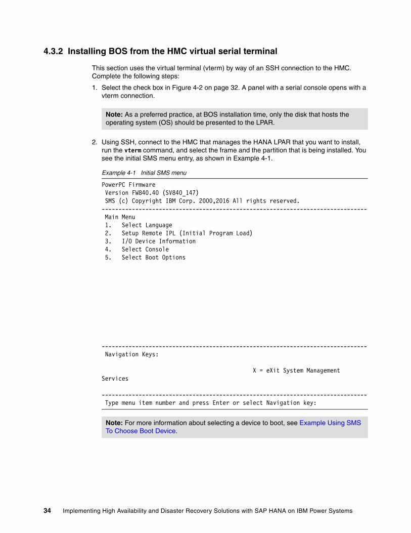
4.3.2 Installing BOS from the HMC virtual serial terminal
This section uses the virtual terminal (vterm) by way of an SSH connection to the HMC. Complete the following steps:
1. Select the check box in Figure 4-2 on page 32. A panel with a serial console opens with a vterm connection.
2. Using SSH, connect to the HMC that manages the HANA LPAR that you want to install, run the vterm command, and select the frame and the partition that is being installed. You see the initial SMS menu entry, as shown in Example 4-1.
Example 4-1 Initial SMS menu
PowerPC Firmware Version FW840.40 (SV840_147) SMS (c) Copyright IBM Corp. 2000,2016 All rights reserved.------------------------------------------------------------------------------- Main Menu 1. Select Language 2. Setup Remote IPL (Initial Program Load) 3. I/O Device Information 4. Select Console 5. Select Boot Options
------------------------------------------------------------------------------- Navigation Keys:
X = eXit System Management Services ------------------------------------------------------------------------------- Type menu item number and press Enter or select Navigation key:
Note: As a preferred practice, at BOS installation time, only the disk that hosts the operating system (OS) should be presented to the LPAR.
Note: For more information about selecting a device to boot, see Example Using SMS To Choose Boot Device.
34 Implementing High Availability and Disaster Recovery Solutions with SAP HANA on IBM Power Systems

3. Select 5. Select Boot Options and press Enter. The panel that is shown in Example 4-2 opens.
Example 4-2 SMS multiboot menu
PowerPC Firmware Version FW840.40 (SV840_147) SMS (c) Copyright IBM Corp. 2000,2016 All rights reserved.------------------------------------------------------------------------------- Multiboot 1. Select Install/Boot Device 2. Configure Boot Device Order 3. Multiboot Startup <OFF> 4. SAN Zoning Support
------------------------------------------------------------------------------- Navigation keys: M = return to Main Menu ESC key = return to previous screen X = eXit System Management Services ------------------------------------------------------------------------------- Type menu item number and press Enter or select Navigation key:
4. Select 1. Select Install/Boot Device and press Enter. The panel that is shown in Example 4-3 opens.
Example 4-3 Select Device Type SMS menu
PowerPC Firmware Version FW840.40 (SV840_147) SMS (c) Copyright IBM Corp. 2000,2016 All rights reserved.------------------------------------------------------------------------------- Select Device Type 1. Tape 2. CD/DVD 3. Hard Drive 4. Network 5. List all Devices
Chapter 4. SUSE Linux Enterprise Server for SAP Applications V12 SP2 installation and customization 35

------------------------------------------------------------------------------- Navigation keys: M = return to Main Menu ESC key = return to previous screen X = eXit System Management Services ------------------------------------------------------------------------------- Type menu item number and press Enter or select Navigation key:
5. Select 2. CD/DVD and press Enter. The panel that is shown in Example 4-4 opens.
Example 4-4 Select Media Type SMS menu
PowerPC Firmware Version FW840.40 (SV840_147) SMS (c) Copyright IBM Corp. 2000,2016 All rights reserved.------------------------------------------------------------------------------- Select Media Type 1. SCSI 2. SAN 3. SAS 4. SATA 5. USB 6. List All Devices
------------------------------------------------------------------------------- Navigation keys: M = return to Main Menu ESC key = return to previous screen X = eXit System Management Services ------------------------------------------------------------------------------- Type menu item number and press Enter or select Navigation key:
6. Because you are using vSCSI, select 1. SCSI and press Enter. The panel that is shown in Example 4-5 opens.
Example 4-5 Select Media Adapter SMS menu
PowerPC Firmware Version FW840.40 (SV840_147) SMS (c) Copyright IBM Corp. 2000,2016 All rights reserved.-------------------------------------------------------------------------------
Note: It is assumed that you are booting from a virtual ISO DVD, as described in “Virtual ISO image installation” on page 26.
36 Implementing High Availability and Disaster Recovery Solutions with SAP HANA on IBM Power Systems

Select Media Adapter 1. U8286.42A.21576CV-V19-C5-T1 /vdevice/v-scsi@30000005 2. List all devices
------------------------------------------------------------------------------- Navigation keys: M = return to Main Menu ESC key = return to previous screen X = eXit System Management Services ------------------------------------------------------------------------------- Type menu item number and press Enter or select Navigation key:
7. If the vSCSI adapter is properly configured, you see it in the SMS menu, as shown in Example 4-5 on page 36. Select the correct vSCSI adapter and press Enter. The panel that is shown in Example 4-6 opens.
Example 4-6 Select Device SMS menu
PowerPC Firmware Version FW840.40 (SV840_147) SMS (c) Copyright IBM Corp. 2000,2016 All rights reserved.------------------------------------------------------------------------------- Select Device Device Current Device Number Position Name 1. - SCSI CD-ROM ( loc=U8286.42A.21576CV-V19-C5-T1-L8100000000000000 )
------------------------------------------------------------------------------- Navigation keys: M = return to Main Menu ESC key = return to previous screen X = eXit System Management Services
Chapter 4. SUSE Linux Enterprise Server for SAP Applications V12 SP2 installation and customization 37

------------------------------------------------------------------------------- Type menu item number and press Enter or select Navigation key:
8. Select the vCD device number and press Enter. This shows you a screen similar to Example 4-7.
Example 4-7 Select Task SMS menu
PowerPC Firmware Version FW840.40 (SV840_147) SMS (c) Copyright IBM Corp. 2000,2016 All rights reserved.------------------------------------------------------------------------------- Select Task
SCSI CD-ROM ( loc=U8286.42A.21576CV-V19-C5-T1-L8100000000000000 )
1. Information 2. Normal Mode Boot 3. Service Mode Boot
------------------------------------------------------------------------------- Navigation keys: M = return to Main Menu ESC key = return to previous screen X = eXit System Management Services ------------------------------------------------------------------------------- Type menu item number and press Enter or select Navigation key:
9. Select 2. Normal Mode Boot and press Enter. The panel that is shown in Example 4-8 opens.
Example 4-8 Confirming the exit of the SMS mode menu
PowerPC Firmware Version FW840.40 (SV840_147) SMS (c) Copyright IBM Corp. 2000,2016 All rights reserved.------------------------------------------------------------------------------- Are you sure you want to exit System Management Services? 1. Yes 2. No
Note: If the CD/DVD is already set up as Current Position of boot number 1, choosing the boot device is optional.
38 Implementing High Availability and Disaster Recovery Solutions with SAP HANA on IBM Power Systems

------------------------------------------------------------------------------- Navigation Keys:
X = eXit System Management Services ------------------------------------------------------------------------------- Type menu item number and press Enter or select Navigation key:
10.Select 1. Yes and press Enter. You exit from SMS mode and boot from the SUSE installation media. After a few seconds, you see the GRUB boot main menu, as shown in Example 4-9.
Example 4-9 GRUB boot main menu
SUSE Linux Enterprise 12 SP2
+----------------------------------------------------------------------------+ |*Installation | | Rescue System | | Upgrade | | Check Installation Media | | local | | Other options... | | | | | | | | | | | | | +----------------------------------------------------------------------------+
Use the ^ and v keys to select which entry is highlighted. Press enter to boot the selected OS, `e' to edit the commands before booting or `c' for a command line.
Chapter 4. SUSE Linux Enterprise Server for SAP Applications V12 SP2 installation and customization 39

11.Move the arrow up until the Installation menu entry is highlighted. Then, press the e key to edit the commands. The window that is shown in Example 4-10 opens.
Example 4-10 GRUB Edit Installation submenu
SUSE Linux Enterprise 12 SP2
+----------------------------------------------------------------------------+ |setparams 'Installation' | | | | echo 'Loading kernel ...' | | linux /boot/ppc64le/linux | | echo 'Loading initial ramdisk ...' | | initrd /boot/ppc64le/initrd | | | | | | | | | | | | | +----------------------------------------------------------------------------+
Minimum Emacs-like screen editing is supported. TAB lists completions. Press Ctrl-x or F10 to boot, Ctrl-c or F2 for a command-line or ESC to discard edits and return to the GRUB menu.
For this installation, we know that the network device is eth0, which is going to be used for the VNC installation. We also know the IP address that is going to be used on that interface, which in this case is 10.10.12.83/24. We also know that the IP gateway is 10.10.12.1 and the DNS servers are 10.10.12.10 and 10.10.12.9. The host name is going to be redhana001 and the proxy IP address and port with no user authentication. Append to the Linux line the text that is shown in Example 4-11.
The reason that we are setting a proxy is that in our lab this is the option to access the SUSE registration and updates. If you have a system that has direct access to the internet or uses the Subscription Management Tool, you can ignore the proxy part.
Example 4-11 Options to append to the Linux entry in GRUB
ifcfg=eth0=10.10.12.83/24,10.10.12.1,10.10.12.10 hostname=redhana001 vnc=1 vncpassword=passw0rd proxy=http://10.10.16.10:3128
Note: If no key is pressed before the countdown ends on the GRUB main boot menu, a default installation is performed. This is most likely not what you need, so if necessary, start from the boot partition step that is described in 4.3.1, “Starting the LPAR in SMS mode” on page 31.
Note: If you are not sure of the network interface name, you can try eth* instead of eth0, which sets the information in all eth devices.
Note: Adapt your needs as needed by using the following format:
ifcfg=eth0=<IP Address>/<Netmask range>,<Gateway>,<nameserver> hostname=<host name> vnc=1 vncpassword='VNCPASSWORD' proxy=http://USER:[email protected]:PORT
40 Implementing High Availability and Disaster Recovery Solutions with SAP HANA on IBM Power Systems

After appending your information to the Linux entry in GRUB, the panel that is shown in Example 4-12 opens.
Example 4-12 Appended configuration to the GRUB Linux line
SUSE Linux Enterprise 12 SP2
+----------------------------------------------------------------------------+ |setparams 'Installation' | | | | echo 'Loading kernel ...' | | linux /boot/ppc64le/linux ifcfg=eth0=10.10.12.83/24,10.10.12.1,10.10.12.1\| |0 hostname=redhana001 proxy=http://10.10.16.10:3128 vnc=1 vncpas\| |sword=passw0rd | | echo 'Loading initial ramdisk ...' | | initrd /boot/ppc64le/initrd | | | | | | | | | +----------------------------------------------------------------------------+
Minimum Emacs-like screen editing is supported. TAB lists completions. Press Ctrl-x or F10 to boot, Ctrl-c or F2 for a command-line or ESC to discard edits and return to the GRUB menu.
12.Press Ctrl+x, which starts the SUSE installation media with the chosen parameters on GRUB. After a couple of minutes, the panel that is shown in Example 4-13 opens.
Example 4-13 Starting YaST2 and VNC boot message
starting VNC server...A log file will be written to: /var/log/YaST2/vncserver.log ...
****** You can connect to <host>, display :1 now with vncviewer*** Or use a Java capable browser on http://<host>:5801/***
(When YaST2 is finished, close your VNC viewer and return to this window.)
Active interfaces:
eth0: 2e:82:88:20:14:1e 10.10.12.83/24 fe80::2c82:88ff:fe20:141e/64
*** Starting YaST2 ***
Chapter 4. SUSE Linux Enterprise Server for SAP Applications V12 SP2 installation and customization 41

4.3.3 Installing SUSE by using YaST2 and VNC
Complete the following steps:
1. Use the VNC client or the web browser to connect to the GUI that is hosting the YaST2 installer. We use a VNC client. To connect to the YaST2 installer, input the IP address of the server (10.10.12.83) with VNC port 5901. When prompted for a password, use the password that is passed as the parameter, as shown in Example 4-11 on page 40.
After you connect, the Language, Keyboard, and License agreement window opens, as shown in Figure 4-4.
Figure 4-4 YaST2 Language, Keyboard, and License Agreement window
42 Implementing High Availability and Disaster Recovery Solutions with SAP HANA on IBM Power Systems

2. Select your language and keyboard settings, and if you agree with the SUSE license terms, select the I agree to the License Terms check box, and click Next.
The System Probing Yast2 window opens, where you can enable multipath in this setup, as shown in Figure 4-5.
Figure 4-5 Yast2 System Probing multipath window
3. Click Yes to activate multipath in this installation.
Note: If you do not see the multipath window, there is a problem with the storage configuration. Before continuing with the installation, see 3.2, “Virtual I/O Server” on page 24.
Chapter 4. SUSE Linux Enterprise Server for SAP Applications V12 SP2 installation and customization 43

The Registration window opens, as shown in Figure 4-6.
Figure 4-6 YaST2 Registration window
4. In this scenario, we use the scc.suse.com system to register this installation. If your setup has a local SMT server, you can also use it instead.
Note: If you do not register now, you must do it later before the HANA DB software is installed.
44 Implementing High Availability and Disaster Recovery Solutions with SAP HANA on IBM Power Systems

After you input the registration information, click Next. When the registration completes, a window opens that offers to enable the update repositories, as shown in Figure 4-7.
Figure 4-7 YaST2 update repositories window
Chapter 4. SUSE Linux Enterprise Server for SAP Applications V12 SP2 installation and customization 45

5. Click Yes to enable the update repositories. The Extension and Module Selection window opens, as shown in Figure 4-8.
Figure 4-8 YaST2 Extension and Module Selection window
46 Implementing High Availability and Disaster Recovery Solutions with SAP HANA on IBM Power Systems

6. Select the IBM DLPAR Utils for SLE 12 ppc64le and IBM DLPAR sdk for SLE 12 ppc64le extensions, and click Next. The IBM DLPAR Utils for SLE 12 ppc64le License Agreement window opens, as shown in Figure 4-9.
Figure 4-9 Yast2 IBM DLPAR Utils for SLE 12 ppc64le License Agreement window
Chapter 4. SUSE Linux Enterprise Server for SAP Applications V12 SP2 installation and customization 47

7. If you agree with the license terms, select I Agree to the License Term and click Next. The IBM DLPAR sdk for SLE 12 ppc64le License Agreement window opens, as shown in Figure 4-10.
Figure 4-10 Yast2 IBM DLPAR sdk for SLE 12 ppc64 License Agreement window
48 Implementing High Availability and Disaster Recovery Solutions with SAP HANA on IBM Power Systems

8. If you agree with the license terms, select I Agree to the License Terms and click Next. The Import GnuPG Key for IBM-DLPAR-utils repository window opens, as shown in Figure 4-11.
Figure 4-11 Yast2 Import GnuPG Key for IBM-DLPAR-utils repository window
Chapter 4. SUSE Linux Enterprise Server for SAP Applications V12 SP2 installation and customization 49

9. After you check that the ID and Fingerprint are correct, click Trust. The Import GnuPG Key for IBM-DLPAR-utils repository window opens, as shown in Figure 4-12.
Figure 4-12 Yast2 Import GnuPG Key for IBM-DLPAR-Adv-toolchain repository window
50 Implementing High Availability and Disaster Recovery Solutions with SAP HANA on IBM Power Systems

10.After you check that the ID and Fingerprint are correct, click Trust. The Choose Operation System Edition selection window opens, as shown in Figure 4-13.
Figure 4-13 YaST2 Choose Operation System Edition window
Chapter 4. SUSE Linux Enterprise Server for SAP Applications V12 SP2 installation and customization 51

11.Select SUSE Linux Enterprise Server for SAP Applications. Leave Enable RDP (Remote Desktop Protocol) Service and open in Firewall (the default) selected. Click Next. The Add-On Product Installation window opens, as shown in Figure 4-14.
Figure 4-14 YaST2 Add-On Product Installation window
Note: Although RDP is not a requirement, we found that using RDP for operations is a common practice in SAP Landscape. If that is not your case, clear the check box.
52 Implementing High Availability and Disaster Recovery Solutions with SAP HANA on IBM Power Systems

12.No changes are needed in this window. Click Next. The Suggested Partitioning window opens, as shown in Figure 4-15.
Figure 4-15 YaST2 Suggested Partitioning window
13.There is no need to change the suggested partitioning. Click Next.
Note: Although you can change the partitioning, there is no actual requirement to do so. For consistency, use the suggested defaults for the partitioning. If you change them, use Btrfs because it is the default for SUSE V12.
Chapter 4. SUSE Linux Enterprise Server for SAP Applications V12 SP2 installation and customization 53

The Clock and Time Zone window opens, as shown in Figure 4-16.
Figure 4-16 YaST2 Clock and Time Zone window
14.Select the time zone for your system and click Next.
The Password for the System Administrator root window opens, as shown in Figure 4-17 on page 55.
Note: You can click Other Settings and configure the Network Time Protocol (NTP) settings. However, if you join a domain, we do not show those steps at installation time to keep these instructions more generic. For more information about how to set up the NTP client after installation, see SUSE Doc: Administration Guide - Time Synchronization with NTP.
54 Implementing High Availability and Disaster Recovery Solutions with SAP HANA on IBM Power Systems

Figure 4-17 YaST2 Password for the System Administrator root window
15.After you input the password and confirm it, click Next.
Note: If YaST2 states that your password is weak, you see a warning. Input a stronger password.
Chapter 4. SUSE Linux Enterprise Server for SAP Applications V12 SP2 installation and customization 55

The Installation Settings window opens, as shown in Figure 4-18.
Figure 4-18 YaST2 Installation Settings default window
16.Click the Software link. The window that is shown in Figure 4-19 on page 57 opens.
Note: In our scenario, we install Gnome and other patterns that are not listed as required but optional. You can modify the patterns that you want to install. What you select must adhere to SAP Note 1984787. Use the current version.
56 Implementing High Availability and Disaster Recovery Solutions with SAP HANA on IBM Power Systems

Figure 4-19 YaST2 Software window
17.In the Software selection, click the SAP HANA Server Base and High Availability patterns. Click OK.
Note: If you are installing a stand-alone HANA DB without SUSE high availability (HA), you can select only the SAP HANA Server Base pattern.
Chapter 4. SUSE Linux Enterprise Server for SAP Applications V12 SP2 installation and customization 57

Depending on the installation source on your DVD, you might see a warning when you select the SAP HANA Server Base pattern, as shown in Figure 4-20.
Figure 4-20 YaST2 SAP HANA Server Base pattern krb5-32bit warning window
If this is your case, either select 2 break patterns-sap-hana-12.2.12.1.ppc64le by ignoring some of its dependencies. Click OK -- Try Again, or request from SUSE an updated installation source that has this issue already fixed.
18.Accept the patterns by clicking OK. You are back in the Software window but with the patterns selected, as shown in Figure 4-21 on page 59.
Note: SUSE is aware of this issue, and at the time of writing is working on a fix for it.
58 Implementing High Availability and Disaster Recovery Solutions with SAP HANA on IBM Power Systems

Figure 4-21 YaST2 Software with patterns selected window
19.Click disable for the Firewall and SSH menu. If your HANA installation requires hardening at the OS level, see Operating System Security Hardening Guide for SAP HANA.
Chapter 4. SUSE Linux Enterprise Server for SAP Applications V12 SP2 installation and customization 59

After the firewall is disabled, you see the window that shown in Figure 4-22.
Figure 4-22 YaST2 Software window all selections for installation
20.Click Install to start the installation. On the confirmation window, click Install if you are ready to perform the installation.
After several minutes, the installer completes and updates the system. The system also restarts so that you can then connect by using RDP or SSH when the installation completes.
4.3.4 Installing the service and productivity tools from IBM for Power Systems
If you did not install the service and productivity tools on the Extension and Module Selection selection that is shown in Figure 4-8 on page 46, then you must install the Service and productivity tools for Linux on Power Servers on the LPAR that you installed. To do so, you must download the binary files from the website and follow the instructions to install the repositories. In this scenario, we download the binary files directly to the LPAR and install them as shown in Example 4-14.
Example 4-14 Installing the service and productivity tools RPM
redhana001:~ # rpm -vih http://public.dhe.ibm.com/software/server/POWER/Linux/yum/download/ibm-power-repo-latest.noarch.rpm
60 Implementing High Availability and Disaster Recovery Solutions with SAP HANA on IBM Power Systems

Retrieving http://public.dhe.ibm.com/software/server/POWER/Linux/yum/download/ibm-power-repo-latest.noarch.rpmwarning: /var/tmp/rpm-tmp.kejIvd: Header V4 DSA/SHA1 Signature, key ID 3e6e42be: NOKEYPreparing... ################################# [100%]Updating / installing... 1:ibm-power-repo-3.0.0-17 ################################# [100%]
After the file is installed in your system, you must run the /opt/ibm/lop/configure command and accept the license.
Regardless, you can add the files by using the CLI or during the BOS installation. After the IBM repositories are visible (run the zypper lr command), you can install the needed software. Follow the instructions for Tools Installation instructions for SUSE. In this scenario, because the LPAR is managed by an HMC, we install the tools that are shown in Example 4-15.
Example 4-15 Installing the service and productivity tools binary files
redhana001:~ # zypper install ibm-power-managed-sles12Refreshing service 'SUSE_Linux_Enterprise_Server_for_SAP_Applications_12_SP2_ppc64le'.Loading repository data...Reading installed packages...Resolving package dependencies...
The following 12 NEW packages are going to be installed: DynamicRM IBMinvscout devices.chrp.base.ServiceRM ibm-power-managed-sles12 ibmPMLinux librtas1 powerpc-utils-python rsct.basic rsct.core rsct.core.utils rsct.opt.storagerm src
The following 12 packages are not supported by their vendor: DynamicRM IBMinvscout devices.chrp.base.ServiceRM ibm-power-managed-sles12 ibmPMLinux librtas1 powerpc-utils-python rsct.basic rsct.core rsct.core.utils rsct.opt.storagerm src
12 new packages to install.Overall download size: 26.3 MiB. Already cached: 0 B. After the operation, additional 85.4 MiB will be used.Continue? [y/n/...? shows all options] (y): yRetrieving package src-3.2.2.1-17038.ppc64le (1/12), 307.5 KiB ( 1.1 MiB unpacked)Retrieving: src-3.2.2.1-17038.ppc64le.rpm .............................................................................................[done (16.3 KiB/s)]
[ snip ]
(12/12) Installing: ibm-power-managed-sles12-1.3.1-0.ppc64le .......................................................................................[done]
Now, you can use dynamic LPAR operations on this LPAR for adding or removing devices, such as CPU or memory.
Chapter 4. SUSE Linux Enterprise Server for SAP Applications V12 SP2 installation and customization 61

4.3.5 Network tuning
For network tuning, follow the instructions in Configuring platform largesend for SAP HANA on SUSE Linux Enterprise Server with VIOS. You must complete the steps first on the VIOS, as described in 3.2, “Virtual I/O Server” on page 24, before doing the tuning at the SUSE LPAR level.
For SR-IOV virtualization, vNIC is not supported. However, you can use SR-IOV-capable adapters. For more information about this topic and future developments, see SAP HANA on IBM Power Systems and IBM System Storage® - Guides SAP HANA on IBM Power Systems and IBM System Storage - Guides.
4.3.6 Configuring the NTP client
If you did not configure the NTP client at installation time (see Figure 4-16 on page 54), you must do so before installing the HANA software. In this scenario, we use two NTP servers that we configure manually. For more information and other configuration options, see SUSE Doc: Administration Guide - Manually Configuring NTP in the Network.
Complete the following steps:
1. Add the IP addresses of the servers to the /etc/ntp.conf file, as shown in Example 4-16.
Example 4-16 Adding NTP IP servers to the ntp.conf file
redhana001:~ # echo server 10.10.12.10 iburst >> /etc/ntp.confredhana001:~ # echo server 10.10.12.9 iburst >> /etc/ntp.conf
2. Enable, start, and query the NTP service by running the systemctl command, as shown in Example 4-17.
Example 4-17 The systemcl enable, start, and query NTP commands
redhana001:~ # systemctl enable ntpdCreated symlink from /etc/systemd/system/multi-user.target.wants/ntpd.service to /usr/lib/systemd/system/ntpd.service.redhana001:~ # systemctl start ntpdredhana001:~ # systemctl status ntpd? ntpd.service - NTP Server Daemon Loaded: loaded (/usr/lib/systemd/system/ntpd.service; enabled; vendor preset: disabled) Drop-In: /run/systemd/generator/ntpd.service.d ••50-insserv.conf-$time.conf Active: active (running) since Wed 2017-07-12 17:05:14 EDT; 1s ago Docs: man:ntpd(1) Process: 42347 ExecStart=/usr/sbin/start-ntpd start (code=exited, status=0/SUCCESS)
Note: Enabling an MTU higher than 1500 can make some hosts unreachable or cause severe performance degradation due to network configurations across the LAN. Check that all the needed configurations are done before enabling jumbo frames. After you enable MTU 9000, check it by running the ping -M do -s 8972 [destinationIP] command. If you cannot reach the host with the ping command, it means fragmentation happened, which means that the MTU change worsened the performance. MTU changes are not changes that can be done only at the OS level, but must be incorporated with the settings in all participating devices on the flow.
62 Implementing High Availability and Disaster Recovery Solutions with SAP HANA on IBM Power Systems

Main PID: 42354 (ntpd) Tasks: 2 (limit: 512) CGroup: /system.slice/ntpd.service ••42354 /usr/sbin/ntpd -p /var/run/ntp/ntpd.pid -g -u ntp:ntp -c /etc/ntp.conf ••42355 ntpd: asynchronous dns resolver
Jul 12 17:05:14 redhana001 systemd[1]: Starting NTP Server Daemon...Jul 12 17:05:14 redhana001 ntpd[42353]: ntpd [email protected] Thu May 18 14:00:11 UTC 2017 (1): StartingJul 12 17:05:14 redhana001 ntpd[42353]: Command line: /usr/sbin/ntpd -p /var/run/ntp/ntpd.pid -g -u ntp...confJul 12 17:05:14 redhana001 ntpd[42354]: proto: precision = 0.072 usec (-24)Jul 12 17:05:14 redhana001 ntpd[42354]: switching logging to file /var/log/ntpJul 12 17:05:14 redhana001 start-ntpd[42347]: Starting network time protocol daemon (NTPD)Jul 12 17:05:14 redhana001 systemd[1]: Started NTP Server Daemon.Hint: Some lines were ellipsized, use -l to show in full.
3. Query the servers by running the ntpq command. You can see that both NTP servers have been contacted, as shown in Example 4-18.
Example 4-18 Querying the NTP servers
redhana001:~ # ntpqntpq> host localhostcurrent host set to localhostntpq> peers remote refid st t when poll reach delay offset jitter==============================================================================*stg-ad02.stg.fo 62.236.120.71 3 u 9 64 3 0.827 -2.343 1.773+stg-ad03.stg.fo 91.207.136.50 3 u 11 64 3 1.564 5.978 15.375ntpq> exit
Chapter 4. SUSE Linux Enterprise Server for SAP Applications V12 SP2 installation and customization 63

64 Implementing High Availability and Disaster Recovery Solutions with SAP HANA on IBM Power Systems

Chapter 5. Storage and file systems setup and customization
This chapter describes the storage layout and file system setup for a HANA on Power Systems installation, and includes both scale-up and scale-out scenarios.
This chapter describes step-by-step implementation instructions for:
� Customizing multipathing with recommended settings
� Customizing multipathing with aliases
� Creating the logical volume manager (LVM) groups and volumes with recommended settings
� Creating the file systems with recommended settings
� Applying Linux I/O subsystem recommended settings
This chapter contains the following topics:
� Storage layout� Linux multipath setup� File system creation and setup� Additional Linux I/O subsystem tuning
5
© Copyright IBM Corp. 2017. All rights reserved. 65

5.1 Storage layout
Before you start, you should review some key aspects.
In 2.1.6, “Storage and file system requirements” on page 15, you set up three file systems for HANA, including /usr/sap. Also, recall the numbers of LUNs and their sizes from that section.
For this publication, our lab environments are configured with 140 GB of memory, so each one of our logical partitions (LPARs) use, according to 2.1.6, “Storage and file system requirements” on page 151, the following specifications:
� Four 100 GB LUNs for the HANA data area
� Four 35 GB LUNs for the HANA log area
� One 50 GB LUN for /usr/sap
The LUNs are locally attached to the node, and each node has the number of LUNs described before, for either a scale-up or scale-out scenario. For a scale-out scenario, you must share each data and log LUN to each of the participating scale-out cluster nodes, which means that you must zone and assign all data and log LUNs to all nodes. For more information, see 5.3.2, “File systems for scale-out systems” on page 80.
Regarding the HANA shared area, there are different approaches depending on whether you are working with a scale-up or with a scale-out scenario.
5.1.1 HANA shared area storage layout for scale-up systems
The HANA shared area is basically where the HANA binary files are stored, along with HANA configuration files.
Scale-up systems do not need to share this area with any other nodes, so the simplest approach is to create a local file system by using locally attached storage disks. In our scale-up lab systems, in addition to the LUNs that are described in 5.1, “Storage layout” on page 66, we also add one 140 GB LUN for HANA shared to the LPAR.
If you are planning on implementing scale-up systems, go to 5.2, “Linux multipath setup” on page 70.
5.1.2 HANA shared area storage layout for scale-out systems
HANA scale-out clusters do not use a local HANA shared area. Instead, they share a file system as a shared area, which means that the binary and configuration files are shared among the participating nodes. This sounds logical, as all nodes must have the same software version for HANA and also the same configuration.
1 Our systems use bigger data and log areas than the guidelines that are presented. Those rules are minimum values.
Important: The log LUNs must either be on SSD or flash arrays, or the storage subsystem must provide a low-latency write cache area.
66 Implementing High Availability and Disaster Recovery Solutions with SAP HANA on IBM Power Systems

Scale-out systems have the following alternatives for sharing the HANA shared area:
� Place the /hana/shared file system on a highly available Network File System (NFS) server and have each scale-out cluster connect to it over the network.
� Create an IBM Spectrum Scale cluster with the scale-out nodes, and create an IBM Spectrum Scale file system for the /hana/shared area.
Both alternatives yield the same result, which ensures all scale-out nodes can access the contents of the /hana/shared file system. Some care must be taken because this file system must be protected with high availability (HA) technologies, or it becomes a single point of failure (SPOF) for the entire scale-out cluster.
You might already have an existing NetWeaver shared file system in your landscape. If so, consider taking advantage of it.
HANA shared area that is managed with IBM Spectrum ScaleIf you use IBM Spectrum Scale to create and manage the HANA shared file system, you can opt to create one LUN per node for the HANA shared area and map them to all scale-out nodes. Then, you create the IBM Spectrum Scale cluster and use these shared LUNs to create the Network Shared Disks (NSDs), and then create an IBM Spectrum Scale file system on them.
Recall that an IBM Spectrum Scale cluster with shared LUNs on all nodes already naturally provides a highly available file system on those LUNs. Even if a given node in the scale-out cluster fails, the /hana/shared content is still accessible by all the remaining nodes. This is a reliable architecture, not complex to implement, and it does not need for any environments to be set up external to the HANA scale-out nodes themselves.
HANA shared area that is managed with NFSThis approach is probably the easiest if you already have a highly available NFS server infrastructure in your enterprise environment. If you do not have one, you must ensure that you create an NFS server with an HA infrastructure.
Here are services that you should consider when implementing a highly available NFS server topology in your environment:
� Highly Available NFS service with DRBD and Pacemaker with SUSE Linux Enterprise High Availability Extension
� Highly Available NFS service on AIX with PowerHA SystemMirror
� High Availability NFS service with DRBD and IBM Tivoli System Automation for Multiplatform (SA MP) with SUSE Linux Enterprise High Availability Extension
For more information about how to set up the NFS server export parameters and the clients mount parameters, see 5.3.2, “File systems for scale-out systems” on page 80.
Note: The size of the HANA shared file system in a scale-out configuration is one times the amount of RAM per every four HANA worker nodes. For example, if you have nodes with 140 GB of memory and you have up to four worker nodes, your shared file system size is 140 GB. If you have 5 - 8 working nodes, the size is 280 GB, and so on.
Caution: You must use an NFS server with HA capability or your overall HANA scale-out cluster will be in jeopardy because of a SPOF in your NFS server system.
Chapter 5. Storage and file systems setup and customization 67

HANA shared area that is managed with Elastic Storage ServerAnother alternative to host the HANA shared area is to use scale-out nodes on an Elastic Storage Server. For more information, see SAP HANA and ESS: A Winning Combination, REDP-5436.
5.1.3 Probing for newly attached disks
If you have not yet attached the data, log, shared, and /usr/sap disks to your system, this section provides a quick and easy way to recognize them without requiring a system restart. Not all Linux distributions provide a system management tool, so in this scenario we provide an approach that works with all distributions.
The multipath -ll (double lowercase L) command shows the storage disks that are attached to your system and the paths to access them. Example 5-1 shows the output of one of our lab systems that contains only the operating system (OS) installation disk that is attached to it.
Example 5-1 Output of the multipath -ll command
hanaonpower:~ # multipath -ll2001738002ae12c88 dm-0 IBM,2810XIV 1size=64G features='2 queue_if_no_path retain_attached_hw_handler' hwhandler='1 alua' wp=rw 2`-+- policy='service-time 0' prio=50 status=active 3 |- 2:0:0:1 sda 8:0 active ready running |- 2:0:1:1 sdb 8:16 active ready running |- 3:0:0:1 sdc 8:32 active ready running |- 3:0:1:1 sdd 8:48 active ready running |- 4:0:0:1 sde 8:64 active ready running |- 4:0:1:1 sdf 8:80 active ready running |- 5:0:0:1 sdg 8:96 active ready running `- 5:0:1:1 sdh 8:112 active ready running
First, check the line that is marked as 1 in the example. In that line, you can identify the LUN ID of the target disk, which in this case is 2001738002ae12c88. Also, the disk device name is dm-0. The characters dm are the standard Linux nomenclature for devices that are managed by the device mapper service. The output tells us that this is an IBM XIV® LUN. So, in summary, you know that the XIV LUN with ID 2001738002ae12c88 is mapped as /dev/dm-0 in that system. As this is the only disk we have so far, we know that this is the OS installation disk.
Line 2 in the output shows some characteristics of that disk. The important information to notice is the disk size, which in this case is 64 GB.
Note: As a preferred practice, install the IBM Storage Host Attachment Kit. The IBM Storage Host Attachment Kit is a software pack that simplifies the task of connecting a host to supported IBM storage systems, and it provides a set of command-line interface (CLI) tools that help host administrators perform different host-side tasks.
For more information, see IBM Storage Host Attachment Kit welcome page.
68 Implementing High Availability and Disaster Recovery Solutions with SAP HANA on IBM Power Systems

Finally, line 3 onwards displays each one of the paths over which the disk is accessed. Our system has four Fibre Channel adapters, and the XIV storage has two controllers, so we see each disk through eight paths. Linux uses an ordinary disk device name for each path by which a disk is accessed, and then joins those disks under a device mapper entry. In our case, the sda through sdh devices are the same OS installation disk that is seen by each of the eight paths, and then joined under the dm-0 device.
You are most likely asking yourself why we have not yet mapped all of the other HANA LUNs to the system. The answer is based on experience. If you do so, SUSE Linux Enterprise Server’s disk probing mechanisms during the OS installation probe all the disks multiple times: once during start, another during the initial disk partitioning layout suggestion, and another one each time you change the partitioning scheme. Probing multiple disks multiple times is a time-consuming task, time that is valuable. So, to save time, attach the HANA LUNs after the OS is installed.
To probe for newly attached disks, complete the following steps:
1. Attach the other LUNs to your system by using your storage management configuration tool.
2. Run the rescan-scsi-bus.sh command. This command sends a loop initialization protocol (lip) signal to probe for new disks on each one of the Fibre Channel connections. This is essentially a bus scan operation that removes and adds devices to the scanned targets, as shown in Example 5-2.
Example 5-2 Issuing rescan-scsi-bus.sh to probe for newly added disks
hanaonpower:~ # rescan-scsi-bus.sh
Now, you can use the multipath -ll command again and verify that all of your disks appear in the listing. Send the output to the grep command to make the output shorter. If you want to see all of the output, run multipath -ll alone. Check that all the disks are there. Example 5-3 shows the output after attaching the remaining LUNs.
Example 5-3 Output of multipath -ll with all LUNs attached to the system
hanaonpower:~ # multipath -ll | grep dm-2001738002ae12c8a dm-6 IBM,2810XIV2001738002ae12c89 dm-5 IBM,2810XIV2001738002ae12c88 dm-0 IBM,2810XIV2001738002ae12c8f dm-10 IBM,2810XIV2001738002ae12c8e dm-8 IBM,2810XIV2001738002ae12c8d dm-9 IBM,2810XIV2001738002ae12c8c dm-7 IBM,2810XIV2001738002ae12c8b dm-4 IBM,2810XIV2001738002ae12c92 dm-13 IBM,2810XIV2001738002ae12c91 dm-12 IBM,2810XIV2001738002ae12c90 dm-11 IBM,2810XIV
Note: By design, all paths to the XIV storage devices are active. Other storage device types, such as IBM Spectrum Virtualize™ (formerly IBM SAN Volume Controller), work with active and passive paths.
Chapter 5. Storage and file systems setup and customization 69

Notice in Example 5-3 on page 69 that we have a total of 11 disks: dm-0, dm-4, dm-5, dm-6, dm-7, dm-8, dm-9, dm-10, dm-11, dm-12, and dm-13. Also, these names can change when the system restarts. It is not a preferred practice to rely on the device naming. A better approach is to use aliases for the disks. Section 5.2, “Linux multipath setup” on page 70 provides information about how to use aliases for the disks.
5.2 Linux multipath setup
Linux systems access disks over multiple paths by using its multipathing service. The configuration file that controls access is /etc/multipath.conf. This file is not created during the default Linux installation, so it must be created and populated based on your environment.
Each storage subsystem vendor has its own preferred practices for setting up the multipathing parameters for Linux. Check your storage vendor’s documentation for their specific recommendations.
The first piece of information that you must know about the /etc/multipath.conf file is that it is composed of four sections:
� The defaults section: Contains the parameters values that are applied to the devices.
� The blacklist section: Excludes devices in this list from being applied the default or specific device parameter values.
� The multipaths section: Defines aliases for the disks.
� The devices section: Overrides the default parameters section to enable specific parameter values according to the storage in use.
Example 5-4 is a fully functional multipath.conf file that is built for an IBM XIV Storage System. We reference this file throughout this chapter to explain the concepts behind it.
Example 5-4 A multipath.conf file for IBM XIV storage
hanaonpower:~ # cat /etc/multipath.confdefaults { user_friendly_names yes}
blacklist { devnode "^(ram|raw|loop|fd|md|dm-|sr|scd|st)[0-9]*" devnode "^(hd|xvd|vd)[a-z]*"}
multipaths {
#ROOTVG multipath { wwid 2001738002ae12c88 alias ROOTVG }
#USRSAP multipath { wwid 2001738002ae12c89 alias USRSAP }
70 Implementing High Availability and Disaster Recovery Solutions with SAP HANA on IBM Power Systems

#HANA DATA multipath { wwid 2001738002ae12c8c alias HANA_DATA_1_1 }
multipath { wwid 2001738002ae12c8d alias HANA_DATA_1_2 }
multipath { wwid 2001738002ae12c8e alias HANA_DATA_1_3 }
multipath { wwid 2001738002ae12c8f alias HANA_DATA_1_4 }
#HANA LOG multipath { wwid 2001738002ae12c8a alias HANA_LOG_1_1 }
multipath { wwid 2001738002ae12c90 alias HANA_LOG_1_2 }
multipath { wwid 2001738002ae12c91 alias HANA_LOG_1_3 }
multipath { wwid 2001738002ae12c92 alias HANA_LOG_1_4 }
#HANA SHARED multipath { wwid 2001738002ae12c8b alias HANA_SHARED01 }}
devices { device { vendor "IBM" product "2810XIV"
Chapter 5. Storage and file systems setup and customization 71

path_selector "round-robin 0" path_grouping_policy multibus rr_min_io 15 path_checker tur failback 15 no_path_retry queue }}
Let us analyze each one of the four sections of this multipath.conf file.
The defaults sectionThe defaults section in multipath.conf contains the parameters and values that are applied to all disks in the system. In this case, the only one that is uses in our HANA environments is the user_friendly_names parameter, which is set to yes.
The user_friendly_names parameter instructs the system to either not use friendly names (no, which is the default option) and instead use the LUN WWID to name the devices under the /dev/mapper directory, or use some better naming, such as /dev/mapper/mpath<n> when using friendly names. Even though the form mpath<n> looks better than the LUN WWID for listing the disks, we still recommend overriding the disk names with custom aliases entries, as described in “The multipaths section” on page 72.
For more information about user_friendly_names, see SUSE Doc: Storage Administration Guide - Configuring User-Friendly Names or Alias Names.
The blacklist sectionThe blacklist section instructs the system to ignore the devices in the list when applying the multipath settings that are defined in the multipath.conf file. Usually, devices that are not multipathed are put into this list. Example 5-4 on page 70 has a standard blacklist that is used in implementations in the field.
For more information about blacklisting devices, see SUSE Doc: Storage Administration Guide - Blacklisting Non-Multipath Devices.
The multipaths sectionThis section is where you define aliases for your disks. Although aliasing does not bring any performance advantage to your setup, it brings in ease of management and avoids problems with device renaming across system restarts. Consider using aliases in your implementation.
Example 5-4 on page 70 creates a multipath { } entry for each one of our 11 disks. Each entry contains a description for the LUN WWID and then the alias we want to assign to it. How do you know which LUN is supposed to be used with each alias? It was probably your storage admin who created the LUNs per your request, so ask what the LUN ID is for each one of the LUNs that are created for you. Verify this information with the output of the multipath -ll command, as shown in Example 5-3 on page 69, and check that the LUN IDs and size match what you are expecting.
After you have this information, populate your multipath.conf file.
Important: Check that you correctly assign the log LUN ID to your log disk alias, especially if you are directly specifying an SSD or flash disk to be used as the HANA log area.
72 Implementing High Availability and Disaster Recovery Solutions with SAP HANA on IBM Power Systems
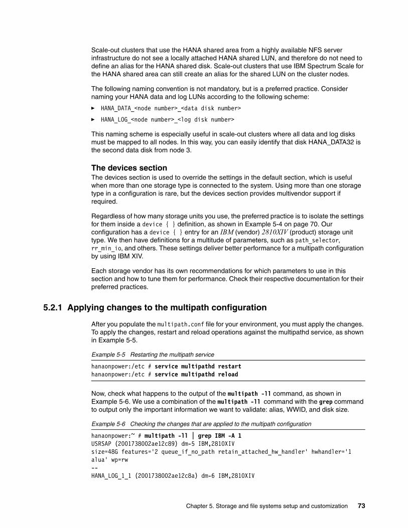
Scale-out clusters that use the HANA shared area from a highly available NFS server infrastructure do not see a locally attached HANA shared LUN, and therefore do not need to define an alias for the HANA shared disk. Scale-out clusters that use IBM Spectrum Scale for the HANA shared area can still create an alias for the shared LUN on the cluster nodes.
The following naming convention is not mandatory, but is a preferred practice. Consider naming your HANA data and log LUNs according to the following scheme:
� HANA_DATA_<node number>_<data disk number>
� HANA_LOG_<node number>_<log disk number>
This naming scheme is especially useful in scale-out clusters where all data and log disks must be mapped to all nodes. In this way, you can easily identify that disk HANA_DATA32 is the second data disk from node 3.
The devices sectionThe devices section is used to override the settings in the default section, which is useful when more than one storage type is connected to the system. Using more than one storage type in a configuration is rare, but the devices section provides multivendor support if required.
Regardless of how many storage units you use, the preferred practice is to isolate the settings for them inside a device { } definition, as shown in Example 5-4 on page 70. Our configuration has a device { } entry for an IBM (vendor) 2810XIV (product) storage unit type. We then have definitions for a multitude of parameters, such as path_selector, rr_min_io, and others. These settings deliver better performance for a multipath configuration by using IBM XIV.
Each storage vendor has its own recommendations for which parameters to use in this section and how to tune them for performance. Check their respective documentation for their preferred practices.
5.2.1 Applying changes to the multipath configuration
After you populate the multipath.conf file for your environment, you must apply the changes. To apply the changes, restart and reload operations against the multipathd service, as shown in Example 5-5.
Example 5-5 Restarting the multipath service
hanaonpower:/etc # service multipathd restarthanaonpower:/etc # service multipathd reload
Now, check what happens to the output of the multipath -ll command, as shown in Example 5-6. We use a combination of the multipath -ll command with the grep command to output only the important information we want to validate: alias, WWID, and disk size.
Example 5-6 Checking the changes that are applied to the multipath configuration
hanaonpower:~ # multipath -ll | grep IBM -A 1USRSAP (2001738002ae12c89) dm-5 IBM,2810XIVsize=48G features='2 queue_if_no_path retain_attached_hw_handler' hwhandler='1 alua' wp=rw--HANA_LOG_1_1 (2001738002ae12c8a) dm-6 IBM,2810XIV
Chapter 5. Storage and file systems setup and customization 73

size=35G features='2 queue_if_no_path retain_attached_hw_handler' hwhandler='1 alua' wp=rw--HANA_LOG_1_2 (2001738002ae12c90) dm-11 IBM,2810XIVsize=35G features='2 queue_if_no_path retain_attached_hw_handler' hwhandler='1 alua' wp=rw--HANA_LOG_1_3 (2001738002ae12c91) dm-12 IBM,2810XIVsize=35G features='2 queue_if_no_path retain_attached_hw_handler' hwhandler='1 alua' wp=rw--HANA_LOG_1_4 (2001738002ae12c92) dm-13 IBM,2810XIVsize=35G features='2 queue_if_no_path retain_attached_hw_handler' hwhandler='1 alua' wp=rw--ROOTVG (2001738002ae12c88) dm-0 IBM,2810XIVsize=64G features='2 queue_if_no_path retain_attached_hw_handler' hwhandler='1 alua' wp=rw--HANA_SHARED01 (2001738002ae12c8b) dm-4 IBM,2810XIVsize=144G features='2 queue_if_no_path retain_attached_hw_handler' hwhandler='1 alua' wp=rw--HANA_DATA_1_4 (2001738002ae12c8f) dm-10 IBM,2810XIVsize=112G features='2 queue_if_no_path retain_attached_hw_handler' hwhandler='1 alua' wp=rw--HANA_DATA_1_3 (2001738002ae12c8e) dm-8 IBM,2810XIVsize=112G features='2 queue_if_no_path retain_attached_hw_handler' hwhandler='1 alua' wp=rw--HANA_DATA_1_2 (2001738002ae12c8d) dm-9 IBM,2810XIVsize=112G features='2 queue_if_no_path retain_attached_hw_handler' hwhandler='1 alua' wp=rw--HANA_DATA_1_1 (2001738002ae12c8c) dm-7 IBM,2810XIVsize=112G features='2 queue_if_no_path retain_attached_hw_handler' hwhandler='1 alua' wp=rw
All disks are now referenced by their aliases and are mapped as symbolic links in the /dev/mapper/ directory. Example 5-7 lists our lab environment system’s disk aliases in /dev/mapper.
Example 5-7 Listing the disk aliases under /dev/mapper
hanaonpower:~ # ls -la /dev/mappertotal 0drwxr-xr-x 2 root root 340 Jun 22 18:50 .drwxr-xr-x 15 root root 5660 Jun 22 18:50 ..lrwxrwxrwx 1 root root 7 Jun 22 18:50 HANA_DATA_1_1 -> ../dm-7lrwxrwxrwx 1 root root 7 Jun 22 18:50 HANA_DATA_1_2 -> ../dm-9lrwxrwxrwx 1 root root 7 Jun 22 18:50 HANA_DATA_1_3 -> ../dm-8lrwxrwxrwx 1 root root 8 Jun 22 18:50 HANA_DATA_1_4 -> ../dm-10lrwxrwxrwx 1 root root 7 Jun 22 18:50 HANA_LOG_1_1 -> ../dm-6lrwxrwxrwx 1 root root 7 Jun 22 18:50 HANA_LOG_1_2 -> ../dm-11lrwxrwxrwx 1 root root 7 Jun 22 18:50 HANA_LOG_1_3 -> ../dm-12
74 Implementing High Availability and Disaster Recovery Solutions with SAP HANA on IBM Power Systems

lrwxrwxrwx 1 root root 7 Jun 22 18:50 HANA_LOG_1_4 -> ../dm-13lrwxrwxrwx 1 root root 7 Jun 22 18:50 HANA_SHARED01 -> ../dm-4lrwxrwxrwx 1 root root 7 Jun 22 18:50 ROOTVG -> ../dm-0lrwxrwxrwx 1 root root 7 Jun 22 18:50 ROOTVG1 -> ../dm-1lrwxrwxrwx 1 root root 7 Jun 22 18:50 ROOTVG2 -> ../dm-2lrwxrwxrwx 1 root root 7 Jun 22 18:50 ROOTVG3 -> ../dm-3lrwxrwxrwx 1 root root 7 Jun 22 18:50 ROOTVG_part1 -> ../dm-1lrwxrwxrwx 1 root root 7 Jun 22 18:50 ROOTVG_part2 -> ../dm-2lrwxrwxrwx 1 root root 7 Jun 22 18:50 ROOTVG_part3 -> ../dm-3lrwxrwxrwx 1 root root 7 Jun 22 18:50 USRSAP -> ../dm-5crw------- 1 root root 10, 236 Jun 22 18:16 control
Now that you have all your LUNs available and using aliases and the multipath daemon is set up according to your storage vendor specifications, it is time to create the HANA file systems.
5.3 File system creation and setup
This section explains how to create the following file systems, along with the setup that each of them requires:
� HANA data file system, mounted on /hana/data/<SID>
� HANA log file system, mounted on /hana/log/<SID>
� HANA shared file system, mounted on /hana/shared
� The /usr/sap file system
Each file system is created on its own disks and its own LVM elements. The <SID> is the SAP ID of the instance that you are installing. For example, if your SID is HP0, then the mount points are /hana/data/HP0 and /hana/log/HP0.
Also, notice that the mount point setup for scale-out is different and is treated as described in 5.3.2, “File systems for scale-out systems” on page 80.
As the implementation for scale-up systems and scale-out clusters differs slightly, we have a separate section for each scenario.
All tunings that are described in this section come from the IBM System Storage Architecture and Configuration Guide for SAP HANA Tailored Datacenter Integration. The values that are used in this publication are current at the time of writing. When you implement HANA on Power Systems, review the white paper to check for current tuning recommendations and guidance.
5.3.1 File systems for scale-up systems
A scale-up system has only local disks, so all HANA file systems are created on these local disks. Also, we used the cosmetic disk aliasing that is described in 5.2, “Linux multipath setup” on page 70.
Note: If you work with Multiple Component One System (MCOS) implementations where more than one HANA instance co-exists in the same OS, then use /hana/data<SID> and /hana/log/<SID> as the mount points for your file systems, and name each one of the instance’s volume groups (VGs) and logical volumes (LVs) uniquely to avoid confusion.
Chapter 5. Storage and file systems setup and customization 75

HANA data file systemStart by creating the HANA data file system on the HANA data disks. Recall that in our alias configuration, our disks are named /dev/mapper/HANA_DATA*. So, we use this wildcard to ease the creation of the LVM VG and LV for the HANA data area.
Example 5-8 shows how to create the HANA data VG. As a preferred practice, call the VG hanadata. You can copy and paste the steps from all of our further examples if you choose do to so. Also, notice that we use some tuning parameters, such as:
� -s 1M: Creates the VG with an extent size of 1 MB.
� --dataalignment 1M: Aligns the start of the data to a multiple of 1 MB.
Example 5-8 Creating the HANA data LVM volume group
hanaonpower:~ # vgcreate -s 1M --dataalignment 1M hanadata /dev/mapper/HANA_DATA* Physical volume "/dev/mapper/HANA_DATA01" successfully created Physical volume "/dev/mapper/HANA_DATA02" successfully created Physical volume "/dev/mapper/HANA_DATA03" successfully created Physical volume "/dev/mapper/HANA_DATA04" successfully created Volume group "hanadata" successfully created
Next, create an LV inside that newly created VG. Name this LV as datalv. Example 5-9 shows this step. Notice that we use some tuning parameters, such as:
� -i 4: Creates the LV by using four stripes across the VG. Because we use four data disks, I/O operations on this LV are spread to all four disks, thus maximizing read and write performance.
� -I 256K: Uses a 256 KB stripe size. Recall from Example 5-8 where we create the VG with an extent size and data alignment of 1 MB. So, having 4 four stripes of 256 KB matches the extent size nicely
Example 5-9 Creating the HANA data LVM volume group
hanaonpower:~ # lvcreate -i 4 -I 256K -l 100%FREE -n datalv hanadata Logical volume "datalv" created.
Finally, create the file system on the newly created LV. The SAP supported file system that we use in our examples is XFS. Example 5-10 shows this step. Notice that we use some tuning parameters, such as:
� -b size=4096: Sets the block size to 4096 bytes.
� -s size=4096: Sets the sector size to 4096 bytes.
Example 5-10 Creating the HANA data file system
hanaonpower:~ # mkfs.xfs -b size=4096 -s size=4096 /dev/mapper/hanadata-datalvmeta-data=/dev/mapper/hanadata-datalv isize=256 agcount=16, agsize=7339968 blks = sectsz=4096 attr=2, projid32bit=1 = crc=0 finobt=0, sparse=0data = bsize=4096 blocks=117439488, imaxpct=25 = sunit=64 swidth=256 blksnaming =version 2 bsize=4096 ascii-ci=0 ftype=1log =internal log bsize=4096 blocks=57343, version=2 = sectsz=4096 sunit=1 blks, lazy-count=1realtime =none extsz=4096 blocks=0, rtextents=0
76 Implementing High Availability and Disaster Recovery Solutions with SAP HANA on IBM Power Systems

HANA log file systemThe creation and setup for the HANA log file system in a scale-up configuration is similar to the HANA data file system. Example 5-11 shows the creation of the HANA log VG. As a preferred practice, name the VG hanalog.
Example 5-11 Creating the HANA log volume group
hanaonpower:~ # vgcreate -s 1M --dataalignment 1M hanalog /dev/mapper/HANA_LOG* Physical volume "/dev/mapper/HANA_LOG01" successfully created Volume group "hanalog" successfully created
Next, comes the creation of the LV. The tuning parameters are the same ones that are used for the data file system, as shown in Example 5-12.
Example 5-12 Creating the HANA log logical volume
hanaonpower:~ # lvcreate -i 4 -I 256K -l 100%FREE -n loglv hanalog Logical volume "loglv" created.
Finally, create the XFS file system on the newly created LV, as shown in Example 5-13. The HANA log file system has the same settings that are used for the HANA data area.
Example 5-13 Creating the HANA log file system
hanaonpower:~ # mkfs.xfs -b size=4096 -s size=4096 /dev/mapper/hanalog-loglvmeta-data=/dev/mapper/hanalog-loglv isize=256 agcount=4, agsize=9437120 blks = sectsz=4096 attr=2, projid32bit=1 = crc=0 finobt=0, sparse=0data = bsize=4096 blocks=37748480, imaxpct=25 = sunit=0 swidth=0 blksnaming =version 2 bsize=4096 ascii-ci=0 ftype=1log =internal log bsize=4096 blocks=18431, version=2 = sectsz=4096 sunit=1 blks, lazy-count=1realtime =none extsz=4096 blocks=0, rtextents=0
HANA shared file systemThe creation and setup of the HANA shared file system in a scale-up configuration is similar to the HANA log file system. Example 5-14 shows the creation of the HANA shared VG. As a preferred practice, name the VG hanashared.
Example 5-14 Creating the HANA shared volume group
hanaonpower:~ # vgcreate hanashared /dev/mapper/HANA_SHARED* Physical volume "/dev/mapper/HANA_SHARED01" successfully created Volume group "hanashared" successfully created
Chapter 5. Storage and file systems setup and customization 77

When you create the LV, there is no need to apply any striping parameters because the shared area is mapped onto one disk only. Example 5-15 shows the creation of the LV.
Example 5-15 Creating the HANA shared logical volume
hanaonpower:~ # lvcreate -l 100%FREE -n sharedlv hanashared Logical volume "sharedlv" created.
Finally, you must create the XFS file system on the newly created LV. For the HANA shared area, there is no need to apply any file system tuning flags, as shown in Example 5-16.
Example 5-16 Creating the HANA shared file system
hanaonpower:~ # mkfs.xfs /dev/mapper/hanashared-sharedlv meta-data=/dev/mapper/hanashared-sharedlv isize=256 agcount=4, agsize=9437120 blks = sectsz=512 attr=2, projid32bit=1 = crc=0 finobt=0, sparse=0data = bsize=4096 blocks=37748480, imaxpct=25 = sunit=0 swidth=0 blksnaming =version 2 bsize=4096 ascii-ci=0 ftype=1log =internal log bsize=4096 blocks=18431, version=2 = sectsz=512 sunit=0 blks, lazy-count=1realtime =none extsz=4096 blocks=0, rtextents=0
The /usr/sap file systemFinally, you must create the /usr/sap file system. We follow the same procedure that was used for creating VGs, LVs, and the file systems, except that there is no tuning needed at all for /usr/sap. Example 5-17 illustrates the creation of the VG. As a preferred practice, name this VG usrsap.
Example 5-17 Creating the /usr/sap volume group
hanaonpower:~ # vgcreate usrsap /dev/mapper/USRSAP Physical volume "/dev/mapper/USRSAP" successfully created Volume group "usrsap" successfully created
Creating the LV for /usr/sap is depicted in Example 5-18.
Example 5-18 Creating the /usr/sap logical volume
hanaonpower:~ # lvcreate -l 100%FREE -n saplv usrsap Logical volume "saplv" created.
Finally, creating the /usr/sap file system is depicted in Example 5-19.
Example 5-19 Creating the /usr/sap file system
hanaonpower:~ # mkfs.xfs /dev/mapper/usrsap-saplv meta-data=/dev/mapper/usrsap-saplv isize=256 agcount=4, agsize=3150848 blks = sectsz=512 attr=2, projid32bit=1 = crc=0 finobt=0, sparse=0data = bsize=4096 blocks=12603392, imaxpct=25 = sunit=0 swidth=0 blksnaming =version 2 bsize=4096 ascii-ci=0 ftype=1log =internal log bsize=4096 blocks=6154, version=2
78 Implementing High Availability and Disaster Recovery Solutions with SAP HANA on IBM Power Systems

= sectsz=512 sunit=0 blks, lazy-count=1realtime =none extsz=4096 blocks=0, rtextents=0
Creating the mount points and configuring /etc/fstabNow that you are done creating the HANA file systems, you must create the mount points and create the entries in the /etc/fstab file in order for the file systems to be mounted by the system.
The HANA mount points are standardized by SAP, and must follow the guidelines that are stated in 5.3, “File system creation and setup” on page 75. Example 5-20 depicts the creation of those mount points according to the proper SAP nomenclature.
Example 5-20 Creating the HANA file systems mount points
hanaonpower:~ # mkdir -p /hana/data/<SID> /hana/log/<SID> /hana/shared /usr/saphanaonpower:~ #
Next, you must append a section to the /etc/fstab file with the definitions of the HANA file systems. Example 5-21contains the entries that you must append, in bold. Do not change any existing entries and remember that your UUIDs are different from the one in Example 5-21.
Example 5-21 Creating entries in /etc/fstab for the HANA file systems
hanaonpower:~ # cat /etc/fstab UUID=58e3f523-f065-4bea-beb5-5ac44313ad30 swap swap defaults 0 0UUID=72f1be2c-022d-49f8-a6e6-a9c02122375a / btrfs defaults 0 0UUID=72f1be2c-022d-49f8-a6e6-a9c02122375a /home btrfs subvol=@/home 0 0UUID=72f1be2c-022d-49f8-a6e6-a9c02122375a /opt btrfs subvol=@/opt 0 0UUID=72f1be2c-022d-49f8-a6e6-a9c02122375a /srv btrfs subvol=@/srv 0 0UUID=72f1be2c-022d-49f8-a6e6-a9c02122375a /usr/local btrfs subvol=@/usr/local 0 0UUID=72f1be2c-022d-49f8-a6e6-a9c02122375a /var/log btrfs subvol=@/var/log 0 0UUID=72f1be2c-022d-49f8-a6e6-a9c02122375a /var/opt btrfs subvol=@/var/opt 0 0UUID=72f1be2c-022d-49f8-a6e6-a9c02122375a /var/spool btrfs subvol=@/var/spool 0 0UUID=72f1be2c-022d-49f8-a6e6-a9c02122375a /.snapshots btrfs subvol=@/.snapshots 0 0
#hana/dev/mapper/hanadata-datalv /hana/data/<SID> xfs defaults 0 0/dev/mapper/hanalog-loglv /hana/log/<SID> xfs defaults 0 0/dev/mapper/hanashared-sharedlv /hana/shared xfs defaults 0 0/dev/mapper/usrsap-saplv /usr/sap xfs defaults 0 0
Finally, as depicted in Example 5-22, mount all the HANA file systems and use df -h to check that they are all mounted. Take the time to check the file system sizes as well.
Example 5-22 Mounting the HANA file systems
hanaonpower:~ # mount -ahanaonpower:~ # df -hFilesystem Size Used Avail Use% Mounted ondevtmpfs 3.5G 0 3.5G 0% /devtmpfs 8.0G 128K 8.0G 1% /dev/shmtmpfs 3.5G 30M 3.5G 1% /runtmpfs 3.5G 0 3.5G 0% /sys/fs/cgroup/dev/mapper/ROOTVG3 62G 11G 50G 19% /
Chapter 5. Storage and file systems setup and customization 79

/dev/mapper/ROOTVG3 62G 11G 50G 19% /var/opt/dev/mapper/ROOTVG3 62G 11G 50G 19% /var/log/dev/mapper/ROOTVG3 62G 11G 50G 19% /.snapshots/dev/mapper/ROOTVG3 62G 11G 50G 19% /srv/dev/mapper/ROOTVG3 62G 11G 50G 19% /opt/dev/mapper/ROOTVG3 62G 11G 50G 19% /home/dev/mapper/ROOTVG3 62G 11G 50G 19% /usr/local/dev/mapper/ROOTVG3 62G 11G 50G 19% /var/spooltmpfs 708M 0 708M 0% /run/user/0/dev/mapper/hanadata-datalv 448G 33M 448G 1% /hana/data/dev/mapper/hanalog-loglv 144G 33M 144G 1% /hana/log/dev/mapper/hanashared-sharedlv 144G 33M 144G 1% /hana/shared/dev/mapper/usrsap-saplv 50G 33M 50G 1% /usr/sap
5.3.2 File systems for scale-out systems
This paper covers the scenarios that are commonly used by customers in the field. The next sections explain and point to existing reference documentation when appropriate.
Regardless of which implementation is used, your nodes must pass the HWCCT File System I/O benchmark tests. These tests are described in 6.4.2, “File system test (XFS)” on page 106.
IBM Elastic Storage Server based environmentsThe IBM Elastic Storage™ Server solution is fully compliant with SAP requirements and makes it simple to manage file systems for HANA scale-out clusters. Using an Elastic Storage Server is supported for all three HANA file systems: data, log, and shared.
In this implementation, all three file systems are created in your Elastic Storage Server infrastructure (data, log, and shared), and all scale-out nodes are connected to them. For more information, see SAP HANA and ESS: A Winning Combination, REDP-5436.
After reviewing that paper, confirm that all of your nodes can see the bolded file systems, as shown in Example 5-23. Our example is from a four-node scale-out cluster, so the file systems are sized.
Example 5-23 HANA scale-out cluster file systems that use Elastic Storage Server
saphana005:~ # mount[ ... snip ...]hanadata on /hana/data type gpfs (rw,relatime)hanalog on /hana/log type gpfs (rw,relatime)hanashared on /hana/shared type gpfs (rw,relatime)saphana005:~ #saphana005:~ # df -hFilesystem Size Used Avail Use% Mounted on[... snip ...]hanadata 1.0T 257M 1.0T 1% /hana/data
Note: The /usr/sap file system is still local to each node, so follow the procedures that are described in “The /usr/sap file system” on page 78 to create it on each scale-out cluster node.
80 Implementing High Availability and Disaster Recovery Solutions with SAP HANA on IBM Power Systems

hanalog 512G 257M 512G 1% /hana/loghanashared 1.0T 257M 1.0T 1% /hana/shared
HANA shared file system by using NFSThe NFS is another alternative to use with HANA scale-out clusters file systems. It is fully supported by SAP. The settings are governed by SAP Note 2099253. In addition to that note, we add some preferred practice configurations from our experience in the field. Using NFS is supported by all three HANA file systems: data, log, and shared.
Basically, you must ensure that your NFS server infrastructure has HA built in, as described in “HANA shared area that is managed with NFS” on page 67. Then, you must create an export on the NFS server to be shared to the HANA clients.
In this paper, we illustrate a single, overall export entry on the NFS server to share the whole /hana folder at once instead of having an entry for data (/hana/data), log (/hana/log), and shared (/hana/shared). If you want to use NFS only for the shared area, which is a more commonly used scenario, then adjust your settings. Even though we use a single export point from the NFS server, each area (data, log, and shared) has its own file system on the NFS server and uses a compliant file system type according to SAP Note 2055470, for example, XFS. Apply all the tunings that are pertinent to each file system, as described in 5.3.1, “File systems for scale-up systems” on page 75.
The NFS server export entry in the /etc/exports file for the /hana directory uses the parameters that are outlined in Example 5-24.
Example 5-24 HANA export on the NFS server
/hana node1(fsid=0, crossmnt, rw, no_root_squash, sync, no_subtree_check) node2(fsid=0, crossmnt, rw, no_root_squash, sync, no_subtree_check) node3(fsid=0, crossmnt, rw, no_root_squash, sync, no_subtree_check) node4(fsid=0, crossmnt, rw, no_root_squash, sync, no_subtree_check)
The export is granted permission to be mounted only by the participating scale-out nodes. This is a preferred practice that is followed to ensure that other systems do not have any access to the HANA file systems of the scale-out cluster. Example 5-24 has the /hana exported to four hosts: node1, node2, node3, and node4. This is a single, long line that contains all hosts for which the entry is exported, with each description node in the following format:
<node_hostname>(fsid=0, crossmnt, rw, no_root_squash, sync, no_subtree_check)
After completing the required configuration on your NFS server with that export, each of the scale-out nodes must mount it by using the correct parameters to ensure optimal performance.
Create a /hana mount point on your scale-out cluster nodes, and add the following line to the /etc/fstab file, where <nfsserver> is the resolvable host name of the NFS server:
<nfsserver>:/hana /hana nfs rw,soft,intr,rsize=8192,wsize=8192 0 0
Run the mount /hana command on all nodes and test whether they can all access that NFS share with read/write permissions.
To obtain the current NFS preferred practices from SAP, see SAP HANA Storage Requirements, especially if you are planning to use NFS for HANA data and log file systems.
Chapter 5. Storage and file systems setup and customization 81

HANA shared file system that uses IBM Spectrum ScaleIBM Spectrum Scale is an alternative to sharing the HANA shared file system among the scale-out nodes. It is not yet supported for sharing the data and log areas, though. If you decide to work with it as the foundation for your /hana/shared file system, then you still must use one of the other solutions that are presented in 5.3.2, “File systems for scale-out systems” on page 80 for data and log.
Installing IBM Spectrum Scale and creating a file system is out of the scope of this publication. For more information about implementing IBM Spectrum Scale, see Implementing IBM Spectrum Scale, REDP-5254. We provide guidance about how to design your IBM Spectrum Scale cluster to ensure HA. No special tuning is required for the file system.
If you decide to use IBM Spectrum Scale for the /hana/shared file system, here are some guidelines that you want to follow:
� Use an odd number of quorum nodes.
� If your scale-out cluster is composed of only two nodes, use IBM Spectrum Scale tiebreaker disks, or add a third Spectrum-Scale-only node for quorum.
� You can choose to create the file system over a single LUN or multiple ones. As a preferred practice, use a number of LUNs equal to the number of IBM Spectrum Scale nodes for better performance.
� Share the LUNs among the scale-out nodes by using the direct-attached methodology, where all nodes have access to them over local Fibre Channel adapters, physical or virtual (N_Port ID Virtualization (NPIV)) adapters.
Storage Connector API for the data and log areasIf you do not plan to work with truly shared file systems for the data and log areas, your scale-out HANA cluster can take advantage of the Storage Connector API to have a standby node take-over the file systems from a failed node and mount it. For more information, see SAP HANA Fibre Channel Storage Connector Admin Guide.
The idea is to use the Storage Connector API is to create as many individual data and log file systems as there are master and worker nodes in the scale-out solution. Figure 5-1 on page 83 illustrates such scenario by using a four-node cluster that is composed of one master node, two worker nodes, and one standby node. The standby node takes over if one of the other nodes fail.
82 Implementing High Availability and Disaster Recovery Solutions with SAP HANA on IBM Power Systems

Figure 5-1 Scale-out cluster: Data and log file systems that are under the Storage Connector API
To get started, create each of the data and log file systems individually, each in its own VG and LV, according to the explanations in sections “HANA data file system” on page 76 and “HANA log file system” on page 77. Recall from “The multipaths section” on page 72 that we recommended naming the LUNs after the standard HANA_DATA_<node number>_<data disk number> and HANA_LOG_<node number>_<log disk number>. So, in a four-node cluster with one master node, two worker nodes, and one standby node, we have the following (in the format <VG name>-<LV name>: participating disks):
� Master (represented as node 1):
– hanadata01-datalv01: /dev/mapper/HANA_DATA_1_*
– hanalog01-loglv01: /dev/mapper/HANA_LOG_1_*
� Worker (represented as node 2):
– hanadata02-datalv02: /dev/mapper/HANA_DATA_2_*
– hanalog02-loglv02: /dev/mapper/HANA_LOG_2_*
� Worker (represented as node 3):
– hanadata03-datalv03: /dev/mapper/HANA_DATA_3_*
– hanalog03-loglv03: /dev/mapper/HANA_LOG_3_*
� Standby (represented as node 4): Does not have associated data or log file systems. but takes over any of the other three nodes file systems if any of these nodes fail.
Important: All of the data and log LUNs are attached to all of the scale-out cluster nodes, so any of the nodes may access and mount the file systems.
Node 3
fail
Node 1
master
Node 1
masterNode 1
master
Node 1
master
Node 1
master
Node 1
masterNode 1
master
data
01
pg01
data
02
pg02
data
03
pg03
data
01
pg01
data
02
pg02
data
03
pg03
Chapter 5. Storage and file systems setup and customization 83

You can create all the file systems on just one node, as all of them have access to all LUNs anyway. You do not need to include the information of the file systems in the /etc/fstab file, as HANA in a scale-out cluster handles the mounting of them automatically when you use the storage connector API. When you are done creating the file systems, run a vgscan command on all nodes and check that they can all see the VGs that you created.
Now, from a disks and file systems perspective, everything is set up to trigger a HANA scale-out installation.
5.4 Additional Linux I/O subsystem tuning
In addition to IBM System Storage Architecture and Configuration Guide for SAP HANA Tailored Datacenter Integration, there is Linux I/O Performance Tuning for IBM System Storage, V1.4. This guide provides additional tuning for the I/O stack of the Linux OS on IBM Power Systems. The information that is provided in the next section was correct at the time of writing. Check for updates to the papers for current details.
5.4.1 I/O device tuning
These changes to the I/O device tuning is applied only if encounter performance issues with your disks. Our definition of a performance issue is not meeting the SAP I/O benchmark numbers that are outlined in Chapter 6, “System evaluation” on page 87.
The first change that you can make to improve performance is to add the rr_min_io_rq parameter to your /etc/multipath.conf “device { }” and set it to 1.
The second change is to increase the queue depth of your disk devices. Consult with your storage vendor about which increment to use and how to make it persistent across restarts. To change the queue depth dynamically without making the changes permanent, run the following command on all your disk devices, and replace <NN> with the chosen queue depth value:
echo <NN> > cat /sys/bus/scsi/devices/<device>/queue_depth
5.4.2 I/O scheduler tuning
The preferred I/O scheduler for HANA disks is NOOP. You can change it in the boot loader configuration by using the elevator boot parameter, in which case the changes are permanent and applied in the next system restart. Example 5-25 shows how to edit your /etc/default/grub file to make this change. You append elevator=noop to the line that starts with GRUB_CMDLINE_LINUX_DEFAULT, as shown in bold.
Example 5-25 Choosing the NOOP I/O scheduler at start time with the elevator parameter
hanaonpower:~ # cat /etc/default/grub# If you change this file, run 'grub2-mkconfig -o /boot/grub2/grub.cfg' afterward to update /boot/grub2/grub.cfg.
# Uncomment to set your own custom distributor. If you leave it unset or empty, the default# policy is to determine the value from /etc/os-releaseGRUB_DISTRIBUTOR=GRUB_DEFAULT=savedGRUB_HIDDEN_TIMEOUT=0
84 Implementing High Availability and Disaster Recovery Solutions with SAP HANA on IBM Power Systems

GRUB_HIDDEN_TIMEOUT_QUIET=trueGRUB_TIMEOUT=8GRUB_CMDLINE_LINUX_DEFAULT="splash=silent quiet showopts elevator=noop"GRUB_CMDLINE_LINUX=""
[... cropped ...]
After making the changes to /etc/default/grub, run grub2-mkconfig to apply the changes to the grub2 boot loader, as shown in Example 5-26.
Example 5-26 Applying the changes to the /etc/default/grub file
hanaonpower:~ # grub2-mkconfig -o /boot/grub2/grub.cfg Generating grub configuration file ...Found linux image: /boot/vmlinux-4.4.21-69-defaultFound initrd image: /boot/initrd-4.4.21-69-defaultdone
Afterward, if you also want to change the scheduler algorithm dynamically without restarting your system, you can do so by using the /sys interface. Every device mapper disk that represents your LUNs has an I/O scheduler interface that is accessed at /sys/block/<dm-X>/queue/scheduler. Example 5-27 shows how to change the I/O scheduler of one of our device mapper disks from cfq to noop.
Example 5-27 Changing the disk I/O scheduler dynamically
To check current (default is cfq):
for BLOCKDEV in `ls -1 /sys/block/| grep sd`; do echo "Device: $BLOCKDEV"; cat /sys/block/$BLOCKDEV/queue/scheduler; done
To set to NOOP on this boot:
for BLOCKDEV in `ls -1 /sys/block/| grep sd`; do echo "Device: $BLOCKDEV"; echo noop > /sys/block/$BLOCKDEV/queue/scheduler; done
You must do the same task for each disk that you have in your system by using their dm-X form. To get a list of such disks, use the commands from Example 5-7 on page 74.
Your environment is ready for HANA to be installed on it.
Chapter 5. Storage and file systems setup and customization 85

86 Implementing High Availability and Disaster Recovery Solutions with SAP HANA on IBM Power Systems

Chapter 6. System evaluation
This chapter describes how to download, configure, and run the current Hardware Configuration Check Tool (HWCCT).
The tool is used for checking the configuration and performance of both scale-up and scale-out environments from a landscape, storage, and network perspective. The results are retained so that you can provide this information to SAP if you have a support call with them. Furthermore, SAP can ask to run these tests again post-deployment.
This chapter contains the following topics:
� HWCCT overview� Tool downloads� Scale-up evaluation� Scale-out evaluation� Further reading
6
Note: Do not run these tests on production systems without the prior approval of SAP support because these tests can adversely affect the performance of the production systems.
© Copyright IBM Corp. 2017. All rights reserved. 87

6.1 HWCCT overview
Each release of SAP HANA contains a version of the HWCCT package. However, this package and its components are frequently updated outside of the cycle of HANA releases. It is imperative that the current version of the HWCCT, Python scripts, and configuration templates are used to produce the most relevant results.
6.1.1 General prerequisites
There are few prerequisites for the tool, but in general you must:
� Have the current SAPCAR tool for your architecture.
� Have exchanged SSH keys between all nodes if the test is to be run across a distributed infrastructure of a scale-out SAP HANA installation.
� Place the HWCCT in a shared location if running it across a distributed infrastructure. For example, /hana/shared/hwcct.
� Ensure that host name resolution by fully qualified domain names (FQDNs) is possible by all systems to be assessed.
6.1.2 SAP Notes
The following SAP Notes are useful in this chapter.
1943937 - Hardware Configuration Check Tool - Central NoteThis note is your first stop when looking at any HWCCT issues because it details the usage of the tool itself. Attached to this note are the current configuration file templates, in JSON format, and a PDF guide about how to use the tool.
2452588 - SAPCAR release and patch informationThis note details the current release of the SAPCAR tool and where to find it. The goal is to ensure that you are always using the current tool and the correct release for your architecture.
2161344 - HWCCT patch noteThis note describes which Python file is used in each scenario, for example, which Python file to use if you are running SAP HANA on ppc64le. Attached to this note are all the current Python files and instructions about how to use them. Usually, they are transferred to the target machine and renamed.
Note: SAP Note 1943937 contains a PDF file called SAP_HANA_Hardware_Configuration_Check_Tool_2.0.pdf. This PDF (see 1.1, “General Prerequisites”) details the prerequisites for running the tool.
Note: SAP Notes are updated regularly. Your first reference for any HWCCT-related issues are SAP Notes. Typically, problems are resolved by using the current HWCCT package with the current Python file and the current JSON formatted configuration file template.
88 Implementing High Availability and Disaster Recovery Solutions with SAP HANA on IBM Power Systems

6.1.3 Current key performance indicators values
The current key performance indicators (KPIs) targets for the file system performance test can be found in the SAP_HANA_Hardware_Configuration_Check_Tool_version.pdf file that is attached to SAP Note 1943937. The values in Table 6-1 are taken from the SAP_HANA_Hardware_Configuration_Check_Tool_2.0.pdf, which is the current file at the time of writing.
Table 6-1 File system test KPI targets
In addition to the values that are included in Table 6-1, note the max trigger time to I/O time ratio, alternatively known as the ratio trigger time (RTT). The current target value for the RTT is included in the SAP_HANA_Hardware_Configuration_Check_Tool_2.0.pdf file.
6.2 Tool downloads
The HWCCT tool comes packaged as a SAR file. To decompress this file, use the SAPCAR utility.
6.2.1 SAPCAR
SAPCAR is an SAP too that is l used for unpacking compressed files that are downloaded from SAP. You must have the current version of the tool for your architecture. To download this tool, go to the SAP Software Center and enter SAPCAR into the search field. The current version at the time of writing is SAPCAR 7.21. Check that you have selected the correct version of the operating system (OS) on which you want to run the tool.
Volume Block sizes
Test file size
KPIs
Initial Write(MBps)
Overwrite (MBps)
Read (MBps)
Latency (µs)
Log 4 KB 5 GB N/A 30 N/A 1000
16 KB 16 GB N/A 120 N/A 1000
1 MB 16 GB N/A 250 250 N/A
Data 4 KB 5 GB N/A N/A N/A N/A
16 KB 16 GB 40 100 N/A N/A
64 KB 16 GB 100 150 250 N/A
1 MB 16 GB 150 200 300 N/A
16 MB 16 GB 200 250 400 N/A
64 MB 16 GB 200 250 400 N/A
Chapter 6. System evaluation 89

In our scenario, we select LINUX ON POWER LE 64-BIT, as shown in Figure 6-1.
Figure 6-1 SAPCAR 7.21 download
Click the file name to download it. Transfer the file to your server and place it in the /hana/shared directory. Make it executable by running the following command:
# chmod 755 SAPCAR_816-70001810.EXE
6.2.2 HWCCT.SAR
The HWCCT is contained within a HWCCT.SAR file that you can download from SAP. To do so, go to the SAP Software Center and click SUPPORT PACKAGES AND PATCHES. Then, click By Alphabetical Index (A-Z) → H → SAP HANA PLATFORM EDITION → SAP HANA PLATFORM EDITION 2.0 → SAP HANA HW CONFIG CHECK 1.0.
A window opens with a list, as shown in Figure 6-2. Download the most recent SAR file or the one most relevant to your landscape (see SAP Note 1943937).
Figure 6-2 HWCCT download
Transfer the SAR file to the /hana/shared/ directory in your machine. Then, follow the instructions in Example 6-1 on page 91 to extract it.
90 Implementing High Availability and Disaster Recovery Solutions with SAP HANA on IBM Power Systems

Example 6-1 Extracting the HWCCT.SAR file
# cd /hana/shared# ./SAPCAR_816-70001810.EXE -xf HWCCT_212_0-70002371.SARSAPCAR: processing archive HWCCT_212_0-70002371.SAR (version 2.01)SAPCAR: 2030 file(s) extracted
You can check which version of the tool that you have installed by running the hwval -version command. You must first source the envprofile.sh file or you receive the error that is shown in Example 6-2.
Example 6-2 Incorrect environment variables that are set for hwval execution
# pwd/hana/shared/hwcct# ./hwval -version./hwval: error while loading shared libraries: libhdbversion.so: cannot open shared object file: No such file or directoryCorrected by:# source envprofile.sh# ./hwval -versionSAP HANA Hardware Configuration Check Tool: 2.00.012.00.1498457145In this case we are running version 2.00.012.00.1498457145.
Chapter 6. System evaluation 91

6.2.3 Python scripts
Within the HWCCT.SAR file, there are two Python scripts that we are interested in: LandscapeTest.py and FilesystemTest.py. Typically, you run the landscape and file system tests by using the Python files that are contained within the HWCCT.SAR file unless you find information that is relevant to your environment in the solution section of SAP Note 2161344 (Figure 6-3).
Figure 6-3 Python files from SAP Note 2161344
For example, if you intend on deploying SAP HANA2 SPS00, you must download the LandscapeTest-Revision200.py file, transfer it to /hana/shared/hwcct, and rename it to LandscapeTest.py.
The FilesystemTest.py file can be copied to the extracted HWCCT.SAR directory, most likely /hana/shared/hwcct. The file name must be FilesystemTest.py.
6.2.4 Configuration file templates
These files are available to download by way of SAP Note 1943937. Here you find the JSON files that correspond to the running the landscape test, a single node file system performance test, a network test for scale-out solutions, and a multinode file system performance test file. These files are displayed in Figure 6-4 on page 93.
92 Implementing High Availability and Disaster Recovery Solutions with SAP HANA on IBM Power Systems

Figure 6-4 JSON configuration file templates that are attached to SAP Note 1943937
6.3 Scale-up evaluation
There are only two tests to run in a scale-up scenario: landscape and file system. This section describes how to configure, run, and interpret these tests and their results. We assume that the HWCCT is extracted to /hana/shared/hwcct and the directory contains something similar to the output that is shown in Example 6-3.
Example 6-3 Contents of /hana/shared/hwcct
# pwd/hana/shared/hwcct# ls -latotal 8416-rwxrwxrwx 1 root root 27671 Jun 26 09:50 FilesystemTest.py-rwxrwxrwx 1 root root 125798 Jun 26 09:50 LandscapeTest.py-rwxrwxrwx 1 root root 7186 Jun 26 09:50 NetworkTest.py-rwxr-xr-x 1 root root 449 Jun 26 09:50 envprofile.shdrwxr-xr-x 2 root root 23 Jun 26 09:50 exampleprofiles-rwxrwxrwx 1 root root 7938 Jun 26 09:50 hwcctApi.py-rwxrwxrwx 1 root root 8374688 Jun 26 09:50 hwval-rwxrwxrwx 1 root root 9080 Jun 26 09:50 hwval_client.py-rwxrwxrwx 1 root root 28728 Jun 26 09:50 hwval_master.pydrwxr-xr-x 4 root root 4096 Jun 26 09:50 lib-rwxr-xr-x 1 root root 625 Jun 26 09:50 localclient.ini-rw-r--r-- 1 root root 898 Jun 26 09:50 manifest-rwxr-xr-x 1 root root 41 Jun 26 09:50 sapprofile.ini-rwxr-xr-x 1 root root 646 Jun 26 09:50 tdiserver.inidrwxr-xr-x 2 root root 6 Jun 26 09:50 trace
Chapter 6. System evaluation 93

Make a backup of the two Python files you are about to overwrite. It is unlikely that you need these backups, but do the backup regardless, as shown in Example 6-4.
Example 6-4 Backup Python files
# pwd/hana/shared/hwcct# cp FilesystemTest.py FilesystemTest.py.backup# cp LandscapeTest.py LandscapeTest.py.backup
6.3.1 Landscape test
This section uses the LandscapeTest-Revision200.py file from SAP Note 2161344. Complete the following steps:
1. Transfer the file to the server and place it in the /hana/shared/hwcct directory. Then, the file must be renamed, as shown in Example 6-5.
Example 6-5 Rename LandscapeTest.py
# ls -la Land*-rwxrwxrwx 1 root root 125798 Jul 4 16:56 LandscapeTest.py-rwxr-xr-x 1 root root 125798 Jul 4 16:55 LandscapeTest.py.backup-rw-r--r-- 1 root root 119394 Jul 4 16:15 LandscapeTest-Revision200.py-rw-r--r-- 1 root root 68683 Jul 4 17:08 LandscapeTest.pyc# cp LandscapeTest-Revision200.py LandscapeTest.py
2. Transfer the latest configuration file template into the same directory. In this case, the file is called landscape_test_cfg_template.json. By default, the file contains the text that is shown in Example 6-6.
Example 6-6 Default landscape_test_cfg_template.json
{"report_id":"<report_id>","use_hdb":false,"blades":["<hostname>"], "tests": [{ "package": "LandscapeTest", "test_timeout": 0, "id": 1, "config": {}, "class": "EvalOs" }
]}
3. You need to change only two entries in this file: <report_id> and <hostname>. The <report_id> field must not contain any spaces. Give your report a meaningful name because this field forms part of the directory name that is created after the test has started. All reports are placed in /hana/shared/hwcct/report_<report_id>_<timestamp>.
94 Implementing High Availability and Disaster Recovery Solutions with SAP HANA on IBM Power Systems
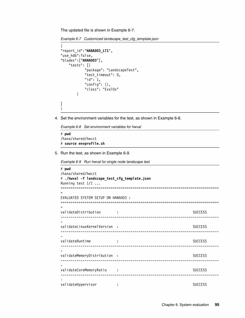
The updated file is shown in Example 6-7.
Example 6-7 Customized landscape_test_cfg_template.json
{"report_id":"HANA003_LT1","use_hdb":false,"blades":["HANA003"], "tests": [{ "package": "LandscapeTest", "test_timeout": 0, "id": 1, "config": {}, "class": "EvalOs" }
]}
4. Set the environment variables for the test, as shown in Example 6-8.
Example 6-8 Set environment variables for hwval
# pwd/hana/shared/hwcct# source envprofile.sh
5. Run the test, as shown in Example 6-9.
Example 6-9 Run hwval for single node landscape test
# pwd/hana/shared/hwcct# ./hwval -f landscape_test_cfg_template.jsonRunning test 1/1 ...================================================================================EVALUATED SYSTEM SETUP ON HANA003 :================================================================================validateDistribution : SUCCESS--------------------------------------------------------------------------------validateLinuxKernelVersion : SUCCESS--------------------------------------------------------------------------------validateRuntime : SUCCESS--------------------------------------------------------------------------------validateMemoryDistribution : SUCCESS--------------------------------------------------------------------------------validateCoreMemoryRatio : SUCCESS--------------------------------------------------------------------------------validateHypervisor : SUCCESS
Chapter 6. System evaluation 95

--------------------------------------------------------------------------------validateCPU : SUCCESS--------------------------------------------------------------------------------validateHTT : SUCCESS--------------------------------------------------------------------------------validateNetwork : SUCCESS--------------------------------------------------------------------------------validateMemory : SUCCESS--------------------------------------------------------------------------------Test Process Summary:---------------------Host configured prepared runTest gotresults cleanedupHANA003:39791 OK OK OK OK OK
6. Investigate any warnings, failures, or skipped results before proceeding with subsequent tests and, ultimately, the SAP HANA installation itself. Often, warnings are associated with a relevant SAP Note.
6.3.2 File system test
Example 6-10 uses the FilesystemTest.py file from SAP Note 2161344. Complete the following steps:
1. Transfer it to the server and place it in the /hana/shared/hwcct directory. This file does not need renaming because it is already in the correct format, as shown in Example 6-10.
Example 6-10 FilesystemTest.py
# ls -la File*-rwxrwxrwx 1 root root 27811 Jul 4 16:56 FilesystemTest.py-rwxr-xr-x 1 root root 27671 Jul 4 16:55 FilesystemTest.py.backup-rw-r--r-- 1 root root 20899 Jul 4 17:27 FilesystemTest.pyc
2. Transfer the latest configuration file template into the same directory. In this case, the file is called singleNode_to_storage_test_cfg_template.json. By default, the file contains the text that is shown in Example 6-11.
Example 6-11 Default singleNode_to_storage_test_cfg_template.json
{"report_id":"<report_id>","use_hdb":false,"blades":["<hostname>"],"tests": [{ "package": "FilesystemTest", "test_timeout": 0, "id": 1, "config": {"mount":{"<hostname>":["<mountpoint_of_data_volume>"]
Note: The Test Process Summary is often confused with test results. This section shows that each component of the test ran successfully. It does not show the results of the tests.
96 Implementing High Availability and Disaster Recovery Solutions with SAP HANA on IBM Power Systems

}, "duration":"short" }, "class": "DataVolumeIO" }, { "package": "FilesystemTest", "test_timeout": 0, "id": 2, "config": {"mount":{"<hostname>":["<mountpoint_of_log_volume>"] }, "duration":"short" }, "class": "LogVolumeIO" }]}
3. As before, there are some values to change in this file. In addition to <report_id> and <hostname>, enter the mount points of the data and log file systems and choose the duration of the test. There are three values for the duration, as shown in Table 6-2.
Table 6-2 Duration parameter values
The test results from a long duration run are retained so that SAP can request them as needed. The updated file is shown in Example 6-12.
Example 6-12 Customized singleNode_to_storage_test_cfg_template.json
{"report_id":"HANA003_FS1","use_hdb":false,"blades":["HANA003"],"tests": [{ "package": "FilesystemTest", "test_timeout": 0, "id": 1, "config": {"mount":{"HANA003":["/hana/data/RB1/"] }, "duration":"short" }, "class": "DataVolumeIO" },
Parameter Description
“duration”:”short” Data file size is 5 GB maximum.
“duration”:”long” Data file size is 16 GB maximum.
“duration”:”verylong”
Data file size is 32 GB maximum.
Tip: Run the short test before the longer tests to ensure that all your settings are correct, and that you can obtain what load it puts on the system and its storage.
Chapter 6. System evaluation 97

{ "package": "FilesystemTest", "test_timeout": 0, "id": 2, "config": {"mount":{"HANA003":["/hana/log/RB1/"] }, "duration":"short" }, "class": "LogVolumeIO" }]}
4. Setting the environment variables for the test, as shown in Example 6-13.
Example 6-13 Set environment variables for hwval
# pwd/hana/shared/hwcct# source envprofile.sh
5. Run the test, as shown in Example 6-14.
Example 6-14 Running hwval for single node file system test
# pwd/hana/shared/hwcct# ./hwval -f singleNode_to_storage_test_cfg_template.jsonRunning test 1/2 ...Test Process Summary:---------------------Host configured prepared runTest gotresults cleanedupHANA003:54147 OK OK OK OK OK
Running test 2/2 ...Host configured prepared runTest gotresults cleanedupHANA003:54147 OK OK OK OK OK
The test completes and produces an output directory that is named /hana/shared/HWCCT/hwcct/report_HANA003_FS1_07_06_2017-21, as shown in Example 6-15.
Example 6-15 File system performance test output
# cd /hana/shared/HWCCT/hwcct/report_HANA003_FS1_07_06_2017-21# ls -la total 0drwxr-xr-x 2 root root 6 Jul 6 21:11 DISKdrwxr-xr-x 2 root root 6 Jul 6 21:11 LINUXdrwxr-xr-x 2 root root 6 Jul 6 21:11 NET# cd DISK# ls -la
Note: Do not miss the trailing / character at the end of the mount points for the data and log file systems.
98 Implementing High Availability and Disaster Recovery Solutions with SAP HANA on IBM Power Systems

total 24-rw-r--r-- 1 root root 12620 Jul 6 21:50 1_contention_data_HANA003-rw-r--r-- 1 root root 6308 Jul 6 22:11 1_contention_log_HANA003
6. Review the contents of the output files. We highlight in bold (Example 6-16) the sections and values that you are looking to compare with the current KPI values, as shown in Table 6-1 on page 89.
Example 6-16 The 1_contention_data_HANA003 file content
********************************************************************************* Output of Results for 16M blocksize *********************************************************************************
Results of Initial Write Test=============================
Throughput Test:----------------
Trigger time:................... 0.000124 s (Throughput: 4.12903e+07 MB/s) Asynchronous submit time:....... 0.225467 s (Throughput: 22708.4 MB/s) Synchronous submit time:........ 0 s (Throughput: 0 MB/s) I/O time:....................... 5.47004 s (Throughput: 936.006 MB/s) Ratio trigger time to I/O time:.2.26689e-05
Latency Test:-------------
I/O time:....................... 9.77332 s (Throughput: 523.874 MB/s) Latency:........................ 30541 us
Results of Overwrite Test=========================
Throughput Test:----------------
Trigger time:................... 0.000117 s (Throughput: 4.37606e+07 MB/s) Asynchronous submit time:....... 0.148804 s (Throughput: 34407.6 MB/s) Synchronous submit time:........ 0 s (Throughput: 0 MB/s) I/O time:....................... 4.63398 s (Throughput: 1104.88 MB/s) Ratio trigger time to I/O time:.2.52482e-05
Latency Test:-------------
I/O time:....................... 9.13322 s (Throughput: 560.59 MB/s) Latency:........................ 28541 us
Results of Read Test
Chapter 6. System evaluation 99

====================
Throughput Test:----------------
Trigger time:................... 0.00011 s (Throughput: 4.65454e+07 MB/s) Asynchronous submit time:....... 0.10199 s (Throughput: 50201 MB/s) Synchronous submit time:........ 0 s (Throughput: 0 MB/s) I/O time:....................... 3.48043 s (Throughput: 1471.07 MB/s) Ratio trigger time to I/O time:.3.16052e-05
Latency Test:-------------
I/O time:....................... 5.28282 s (Throughput: 969.177 MB/s) Latency:........................ 16508 us
********************************************************************************* Output of Results for 16K blocksize *********************************************************************************
Results of Initial Write Test=============================
Throughput Test:----------------
Trigger time:................... 0.112582 s (Throughput: 45477.9 MB/s) Asynchronous submit time:....... 0.461728 s (Throughput: 11088.7 MB/s) Synchronous submit time:........ 0 s (Throughput: 0 MB/s) I/O time:....................... 15.7826 s (Throughput: 324.406 MB/s) Ratio trigger time to I/O time:.0.00713326
Latency Test:-------------
I/O time:....................... 389.874 s (Throughput: 13.1324 MB/s) Latency:........................ 1189 us
Results of Overwrite Test=========================
Throughput Test:----------------
Trigger time:................... 0.102145 s (Throughput: 50124.8 MB/s) Asynchronous submit time:....... 0.123139 s (Throughput: 41579 MB/s) Synchronous submit time:........ 0 s (Throughput: 0 MB/s) I/O time:....................... 11.0929 s (Throughput: 461.554 MB/s) Ratio trigger time to I/O time:.0.00920811
100 Implementing High Availability and Disaster Recovery Solutions with SAP HANA on IBM Power Systems

Latency Test:-------------
I/O time:....................... 150.132 s (Throughput: 34.1032 MB/s) Latency:........................ 458 us
Results of Read Test====================
Throughput Test:----------------
Trigger time:................... 0.085561 s (Throughput: 59840.3 MB/s) Asynchronous submit time:....... 0.128833 s (Throughput: 39741.3 MB/s) Synchronous submit time:........ 0 s (Throughput: 0 MB/s) I/O time:....................... 12.2907 s (Throughput: 416.572 MB/s) Ratio trigger time to I/O time:.0.0069614
Latency Test:-------------
I/O time:....................... 331.739 s (Throughput: 15.4338 MB/s) Latency:........................ 1012 us
The output in Example 6-16 on page 99 is truncated. The tests are repeated for all block sizes, as shown in Example 6-17.
Example 6-17 The 1_contention_log_HANA003 file content
********************************************************************************* Output of Results for 1M blocksize *********************************************************************************
Results of Initial Write Test=============================
Throughput Test:----------------
Trigger time:................... 0.00174 s (Throughput: 2.94252e+06 MB/s) Asynchronous submit time:....... 0.151036 s (Throughput: 33899.2 MB/s) Synchronous submit time:........ 0 s (Throughput: 0 MB/s) I/O time:....................... 9.31975 s (Throughput: 549.37 MB/s) Ratio trigger time to I/O time:.0.0001867
Latency Test:-------------
I/O time:....................... 9.85084 s (Throughput: 519.752 MB/s) Latency:........................ 1923 us
Chapter 6. System evaluation 101

Results of Overwrite Test=========================
Throughput Test:----------------
Trigger time:................... 0.001585 s (Throughput: 3.23028e+06 MB/s) Asynchronous submit time:....... 0.002995 s (Throughput: 1.70951e+06 MB/s) Synchronous submit time:........ 0 s (Throughput: 0 MB/s) I/O time:....................... 3.32615 s (Throughput: 1539.31 MB/s) Ratio trigger time to I/O time:.0.000476525
Latency Test:-------------
I/O time:....................... 8.89202 s (Throughput: 575.796 MB/s) Latency:........................ 1736 us
Results of Read Test====================
Throughput Test:----------------
Trigger time:................... 0.003281 s (Throughput: 1.56049e+06 MB/s) Asynchronous submit time:....... 0.003373 s (Throughput: 1.51793e+06 MB/s) Synchronous submit time:........ 0 s (Throughput: 0 MB/s) I/O time:....................... 3.31022 s (Throughput: 1546.72 MB/s) Ratio trigger time to I/O time:.0.000991171
Latency Test:-------------
I/O time:....................... 7.16112 s (Throughput: 714.971 MB/s) Latency:........................ 1398 us
********************************************************************************* Output of Results for 4K blocksize *********************************************************************************
Results of Initial Write Test=============================
Throughput Test:----------------
Trigger time:................... 0.086844 s (Throughput: 11791.2 MB/s) Asynchronous submit time:....... 2.01562 s (Throughput: 508.029 MB/s) Synchronous submit time:........ 0 s (Throughput: 0 MB/s)
102 Implementing High Availability and Disaster Recovery Solutions with SAP HANA on IBM Power Systems

I/O time:....................... 127.176 s (Throughput: 8.05178 MB/s) Ratio trigger time to I/O time:.0.00068286
Latency Test:-------------
I/O time:....................... 126.098 s (Throughput: 8.12065 MB/s) Latency:........................ 481 us
Results of Overwrite Test=========================
Throughput Test:----------------
Trigger time:................... 0.090236 s (Throughput: 11348 MB/s) Asynchronous submit time:....... 0.013471 s (Throughput: 76015.1 MB/s) Synchronous submit time:........ 0 s (Throughput: 0 MB/s) I/O time:....................... 4.93427 s (Throughput: 207.527 MB/s) Ratio trigger time to I/O time:.0.0182875
Latency Test:-------------
I/O time:....................... 126.986 s (Throughput: 8.06382 MB/s) Latency:........................ 484 us
Results of Read Test====================
Throughput Test:----------------
Trigger time:................... 0.075042 s (Throughput: 13645.6 MB/s) Asynchronous submit time:....... 0.010104 s (Throughput: 101346 MB/s) Synchronous submit time:........ 0 s (Throughput: 0 MB/s) I/O time:....................... 4.36146 s (Throughput: 234.783 MB/s) Ratio trigger time to I/O time:.0.0172056
Latency Test:-------------
I/O time:....................... 68.4614 s (Throughput: 14.9573 MB/s) Latency:........................ 261 us
Again, the output in Example 6-17 on page 101 has been truncated. The tests are repeated for all block sizes.
7. The final value to check in the output of Example 6-17 on page 101, for both data and log, is the largest RTT to I/O trigger time values. In this instance, the largest value is 0.0182875s, which is significantly lower than the maximum value of 0.1s.
Chapter 6. System evaluation 103

6.4 Scale-out evaluation
The evaluation of an SAP HANA scale-out configuration is similar to that of a scale-up configuration. However, the file system test is different because it introduces the network test. The network test is specific to a scale-out solution.
Before proceeding with these tests, it is important that you have configured and verified password-less SSH between all the nodes. Failure to do so results in the tests running incorrectly or not at all.
For ease of use, as a preferred practice, place the HWCCT in a directory that is shared between all nodes in the cluster. Typically, in a scale-out scenario, this setup can be achieved with IBM Spectrum Scale or a Network File System (NFS) share that is mounted as /hana/shared/.
6.4.1 Landscape test
The landscape test is configured and run as shown in 6.3.1, “Landscape test” on page 94. You use the same Python and JSON formatted configuration file templates in the running of these tests. This test must be run on each node. Use the <report_id> field to name the output appropriately so that it is easy to distinguish the reports.
It is possible to run the landscape test across multiple nodes. Check that password-less SSH is configured between the nodes and use a slightly amended configuration file template. You can review what the template looks like in Example 6-18.
Example 6-18 Multiple hosts landscape test configuration file template
{"report_id":"<report_id>","use_hdb":false,"blades":["<hostname1>", "<hostname2>"], "tests": [{ "package": "LandscapeTest", "test_timeout": 0, "id": 1, "config": {}, "class": "EvalOs" }
]}
The template can be adjusted by adding more hosts to line four. In our environment, this file looks like Example 6-19.
Example 6-19 Customized multiple hosts landscape test configuration file template
{"report_id":"HANA007_HANA008_LS1","use_hdb":false,"blades":["HANA007", "HANA008"], "tests": [{ "package": "LandscapeTest", "test_timeout": 0,
104 Implementing High Availability and Disaster Recovery Solutions with SAP HANA on IBM Power Systems

"id": 1, "config": {}, "class": "EvalOs" }
]}
The results are shown in Example 6-20. Although the file name is multiple_landscape_test.json, this is a copy of the landscape_test_cfg_template.json file with additional host names added.
Example 6-20 Multiple landscape tests across multiple hosts
# pwd/hana/shared./hwval -f multiple_landscape_test.jsonRunning test 1/1 ...================================================================================EVALUATED SYSTEM SETUP ON HANA007 :================================================================================validateDistribution : SUCCESS--------------------------------------------------------------------------------validateLinuxKernelVersion : SUCCESS--------------------------------------------------------------------------------validateRuntime : SUCCESS--------------------------------------------------------------------------------validateMemoryDistribution : SUCCESS--------------------------------------------------------------------------------validateCoreMemoryRatio : SUCCESS--------------------------------------------------------------------------------validateHypervisor : SUCCESS--------------------------------------------------------------------------------validateCPU : SUCCESS--------------------------------------------------------------------------------validateHTT : SUCCESS--------------------------------------------------------------------------------validateNetwork : SUCCESS--------------------------------------------------------------------------------validateMemory : SUCCESS--------------------------------------------------------------------------------================================================================================EVALUATED SYSTEM SETUP ON HANA008 :================================================================================validateDistribution : SUCCESS--------------------------------------------------------------------------------validateLinuxKernelVersion : SUCCESS--------------------------------------------------------------------------------validateRuntime : SUCCESS--------------------------------------------------------------------------------validateMemoryDistribution : SUCCESS--------------------------------------------------------------------------------validateCoreMemoryRatio : SUCCESS--------------------------------------------------------------------------------validateHypervisor : SUCCESS--------------------------------------------------------------------------------
Chapter 6. System evaluation 105

validateCPU : SUCCESS--------------------------------------------------------------------------------validateHTT : SUCCESS--------------------------------------------------------------------------------validateNetwork : SUCCESS--------------------------------------------------------------------------------validateMemory : SUCCESS--------------------------------------------------------------------------------Test Process Summary:---------------------Host configured prepared runTest gotresults cleanedupHANA007:51511 OK OK OK OK OKHANA008:48952 OK OK OK OK OK
6.4.2 File system test (XFS)
The file system performance test in a scale-out environment varies significantly from that of a scale-up environment. There are multiple values to amend in the multiNode_to_storage_test_cfg_template.json file. Also, the content varies depending on how many nodes you have in your environment. Typically, a scale-out scenario involves at least three nodes: two worker nodes and one standby node.
Example 6-21 shows two nodes. You can edit this file to add more nodes and more file systems. Carefully copy the sections that you must duplicate and then add the additional hosts and file systems.
Example 6-21 Default two-node multiNode_to_storage_test_cfg_template.json configuration file
{"report_id":"<report_id>","use_hdb":false,"blades":["<hostname_host1>", "<hostname_host2>"],"tests": [{ "package": "FilesystemTest", "test_timeout": 0, "id": 1, "config": {"mount":{"<hostname_host1>":["<mountpoint_of_data_volume_host1>"] }, "duration":"short" }, "class": "DataVolumeIO" }, { "package": "FilesystemTest", "test_timeout": 0, "id": 2, "config": {"mount":{"<hostname_host2>":["<mountpoint_of_data_volume_host2>"] }, "duration":"short" },
106 Implementing High Availability and Disaster Recovery Solutions with SAP HANA on IBM Power Systems

"class": "DataVolumeIO" }, { "package": "FilesystemTest", "test_timeout": 0, "id": 3, "config": {"mount":{"<hostname_host1>":["<mountpoint_of_log_volume_host1>"] }, "duration":"short" }, "class": "LogVolumeIO" }, { "package": "FilesystemTest", "test_timeout": 0, "id": 4, "config": {"mount":{"<hostname_host2>":["<mountpoint_of_log_volume_host2>"] }, "duration":"short" }, "class": "LogVolumeIO" }, { "package": "FilesystemTest", "test_timeout": 0, "id": 5, "config": {"mount":{ "<hostname_host1>":["<mountpoint_of_data_volume_host1>"], "<hostname_host2>":["<mountpoint_of_data_volume_host2>"] }, "duration":"short" }, "class": "DataVolumeIO" }, { "package": "FilesystemTest", "test_timeout": 0, "id": 6, "config": {"mount":{ "<hostname_host1>":["<mountpoint_of_log_volume_host1>"], "<hostname_host2>":["<mountpoint_of_log_volume_host2>"] }, "duration":"short" }, "class": "LogVolumeIO" }]}
Chapter 6. System evaluation 107

Example 6-22 shows how this file looks in a scale-out environment that uses XFS. Our two nodes are HANA007 and HANA008. We call the report HANA007_HANA008_FS1. There are four file systems; /hana/data/RB1/mnt00001, /hana/data/RB1/mnt00002, /hana/log/RB1/mnt00001, and /hana/log/RB1/mnt00002.
Example 6-22 Sample two-node configuration file for scale-out file system test
{"report_id":"HANA007_HANA008_FS1","use_hdb":false,"blades":["HANA007", "HANA008"],"tests": [{ "package": "FilesystemTest", "test_timeout": 0, "id": 1, "config": {"mount":{"HANA007":["/hana/data/RB1/mnt00001"] }, "duration":"short" }, "class": "DataVolumeIO" }, { "package": "FilesystemTest", "test_timeout": 0, "id": 2, "config": {"mount":{"HANA008":["/hana/data/RB1/mnt00002"] }, "duration":"short" }, "class": "DataVolumeIO" }, { "package": "FilesystemTest", "test_timeout": 0, "id": 3, "config": {"mount":{"HANA007":["/hana/log/RB1/mnt00001"] }, "duration":"short" }, "class": "LogVolumeIO" }, { "package": "FilesystemTest", "test_timeout": 0, "id": 4, "config": {"mount":{"HANA008":["/hana/log/RB1/mnt00002"] }, "duration":"short" }, "class": "LogVolumeIO" }, { "package": "FilesystemTest", "test_timeout": 0, "id": 5, "config": {"mount":{
108 Implementing High Availability and Disaster Recovery Solutions with SAP HANA on IBM Power Systems

"HANA007":["/hana/data/RB1/mnt00001"], "HANA008":["/hana/data/RB1/mnt00002"] }, "duration":"short" }, "class": "DataVolumeIO" }, { "package": "FilesystemTest", "test_timeout": 0, "id": 6, "config": {"mount":{ "HANA007":["/hana/log/RB1/mnt00001"], "HANA008":["/hana/log/RB1/mnt00002"] }, "duration":"short" }, "class": "LogVolumeIO" }]}
6.4.3 File system test (IBM Spectrum Scale)
The configuration test file for a scale-out environment that uses IBM Spectrum Scale looks similar to a scale-out environment that uses XFS.
The configuration in Example 6-23 shows how to set up the test for a three-node configuration.
Although the mount point in an IBM Spectrum Scale environment can be /hana/data/, we configure the file in such a way that it tests the performance of the subdirectory. There is technically no difference to /hana/data/ compared to /hana/data/RB1/mnt00001/, but we split them for parity with the XFS test.
Example 6-23 Sample three-node configuration file for file system test that uses IBM Spectrum Scale
{"report_id":"GPFS_FS1","use_hdb":false,"blades":["hana006", "hana007", "hana008"],"tests": [{ "package": "FilesystemTest", "test_timeout": 0, "id": 1, "config": {"mount":{"hana006":["/hana/data/RB1/mnt00001/"] }, "duration":"short" }, "class": "DataVolumeIO" }, { "package": "FilesystemTest",
Chapter 6. System evaluation 109

"test_timeout": 0, "id": 2, "config": {"mount":{"hana007":["/hana/data/RB1/mnt00002/"] }, "duration":"short" }, "class": "DataVolumeIO" },
{ "package": "FilesystemTest", "test_timeout": 0, "id": 2, "config": {"mount":{"hana008":["/hana/data/RB1/mnt00003/"] }, "duration":"short" }, "class": "DataVolumeIO" }, { "package": "FilesystemTest", "test_timeout": 0, "id": 3, "config": {"mount":{"hana006":["/hana/log/RB1/mnt00001/"] }, "duration":"short" }, "class": "LogVolumeIO" }, { "package": "FilesystemTest", "test_timeout": 0, "id": 4, "config": {"mount":{"hana007":["/hana/log/RB1/mnt00002/"] }, "duration":"short" }, "class": "LogVolumeIO" },
{ "package": "FilesystemTest", "test_timeout": 0, "id": 4, "config": {"mount":{"hana008":["/hana/log/RB1/mnt00003/"] }, "duration":"short" }, "class": "LogVolumeIO" }, { "package": "FilesystemTest", "test_timeout": 0, "id": 5, "config": {"mount":{
110 Implementing High Availability and Disaster Recovery Solutions with SAP HANA on IBM Power Systems

"hana006":["/hana/data/RB1/mnt00001/"],"hana007":["/hana/data/RB1/mnt00002/"],"hana008":["/hana/data/RB1/mnt00003/"] }, "duration":"short" }, "class": "DataVolumeIO" }, { "package": "FilesystemTest", "test_timeout": 0, "id": 6, "config": {"mount":{ "hana006":["/hana/log/RB1/mnt00001/"],"hana007":["/hana/log/RB1/mnt00002/"],"hana008":["/hana/log/RB1/mnt00003/"] }, "duration":"short" }, "class": "LogVolumeIO" }]}
6.4.4 Network test
The network test is run in a different way than the landscape and file system performance tests.
There are two executable files in /hana/shared/hwcct/lib. One is the server element (TDINetServer), and one is the client element (TDINetClient).
At the time of writing, the KPI for a bonded 10 Gbit device is 9.0 Gbit/s with a minimum payload of 10 MB with a run length of 10 iterations. This KPI can be found in the current SAP_HANA_Hardware_Configuration_Check_Tool_version.pdf file that is attached to SAP Note 1943937.
As in the earlier tests, you must set the environment variables on both client and server before you run the test.
This section uses hosts HANA006, HANA007, and HANA008. We demonstrate how to run these tests between two of the servers. Of course, if this is a production environment, you must run the test between every possible iteration of nodes. So, you need a test from HANA006 to HANA007, HANA006 to HANA008, HANA007 to HANA006, and so on.
As before, set the environment variables for both client and server, as shown in Example 6-24.
Example 6-24 Setting the environment variables for the network performance test
# pwd/hana/shared/hwcct/lib # source ../envprofile.shhana007:/hana/shared/hwcct/lib # ./TDINetServer
Chapter 6. System evaluation 111

TDI Server startingaccepting requests at 127.0.0.1:4464; 10.10.12.86:4464
Example 6-24 on page 111 shows which IP and which port on which the server is listening. We use this information to populate the fields for the client-side run. The possible switches for the TDINetClient run are displayed by running the script with a -h switch, as shown in Example 6-25.
Example 6-25 TDINetClient help window
# pwd/hana/shared/hwcct/lib# ./TDINetClient -hUsage: TDINetClient -<mode> <host> <port> <size> <iterations> --output <outputtype> mode = o/c/m/s/h with o=optimze (standard) c=measure for a fixed size and check that all data arrives m=measure only with a fixed size s=stop TDINetServer h=help (print this help) size = size of a test string iterations = amount of single tests to build average throughput upon outputtype can be json/short/long
TDINetClient -<o/c/m> <host> <port> is shorthand for TDINetClient -<o/c/m> <host> <port> 1024 25 --output short
TDINetClient -s <host> <port> requires no further parameter TDINetClient -h requires no further parameter
Now, we are ready to run the test. The results are shown in Example 6-26.
Example 6-26 Network test performance results
# pwd/hana/shared/hwcct/lib# ./TDINetClient -m 10.10.12.86 4464 100000000 10Running TDINetClient Mode: Measurement Initial Buffer Size (Byte): 100000000 Iterations: 10 Host: 10.10.12.86 Port: 4464
Result: Server Status: Running Buffer Size (Byte): 100000000 Throughput (MBit/s): 5016
In this instance, the throughput that is achieved is around 5 Gbit/s. This is 5 Gbit/s short of the KPI numbers. If you get this problem, check that you applied all possible network tuning in your environment, as described in 4.3.5, “Network tuning” on page 62.
112 Implementing High Availability and Disaster Recovery Solutions with SAP HANA on IBM Power Systems

6.5 Further reading
The current PDF version of the configuration tool, SAP_HANA_Hardware_Configuration_Check_Tool_version.pdf, is attached to SAP Note 1943937.
This file contains details of combining all these tests into one single run by using the test_config.json file to call each separate test in turn. This is outside of the scope of this document, but is useful if you want to consolidate the effort that is involved in running these tests across multiple environments with multiple servers.
Chapter 6. System evaluation 113

114 Implementing High Availability and Disaster Recovery Solutions with SAP HANA on IBM Power Systems

Chapter 7. SAP HANA software stack installation for a scale-up scenario
This chapter provides the instructions about how to use the SAP HANA on Power Systems installer for a scale-up installation. This chapter covers both the GUI and the text interface installations.
Additionally, this chapter provides a quick guide about how to use SAP HANA Studio to connect to the HANA instance to manage it.
This chapter includes the following topics:
� SAP HANA installation overview� Installation methods� Postinstallation notes
7
© Copyright IBM Corp. 2017. All rights reserved. 115

7.1 SAP HANA installation overview
The SAP HANA installer offers a good degree of flexibility in terms of installation interfaces and installation options.
The available installation interfaces are:
� A GUI interface� A browser-based interface� A text interface
This chapter demonstrates how to perform the installation by using both the GUI and the text interfaces. The results are the same for either approach.
The GUI installation requires installation of the X11 SUSE packages and a VNC server to connect to. If you followed the operating system (OS) installation guidelines that are described in Chapter 4, “SUSE Linux Enterprise Server for SAP Applications V12 SP2 installation and customization” on page 29, you already have an X11 capable with a VNC enabled environment, and all you need to do is to connect to it by using a VNC client.
If you prefer to perform the installation in text mode, all you need is an SSH connection to your system. It is simple because this approach uses a text-based preinstallation wizard to create a response file and then uses it to drive the installation in unattended mode.
From an installation options point of view, HANA enables you to select which components to install. These components are the server, the client, the AFL component, the Smart Data Access component, and so on. In this publication, we install only the server and the client components because we are interested in providing you the guidelines for installing a highly available HANA environment.
Before you start the installation, you need the following information as input for the installer:
� The SAP ID (SID) of the instance that you plan to install.
� The instance number of the instance that you plan to install.
� The passwords that you plan to use for the <sid>adm user, the SYSTEM user, and the SAP Host Agent user (sapadm).
The following sections provide information about how the instance number works. This information is used later to access the instance through HANA Studio, and is also used to assign the port number that is used for communicating with HANA. The port number has the form of 3<instance number>15. If you use an instance number of 00, then the port number that HANA listens to is 30015.
Also, if you plan to use SAP HANA Systems Replication (HSR) between two HANA instances, remember that the replication itself uses the next instance number to assign the port number for replication services. For example, if the instances you want to replicate have a SID / instance number of RB1 / 00, then connecting to those instances happens over port 30015 and the replication between them over port 30115.
Note: As documented by SAP Note 2423367, starting with HANA 2.0 SPS1, all databases (DBs) are configured in multitenant mode only. There is no option to install a single-container instance.
116 Implementing High Availability and Disaster Recovery Solutions with SAP HANA on IBM Power Systems

7.2 Installation methods
This section guides you through the installation process of HANA. If you have not yet done so, download the installer files for HANA, as described in 2.2.3, “Getting the HANA on Power Systems installation files” on page 19. At the time of writing, the HANA 2.0 on Power Systems installer is composed of four compressed files as follows (the first one has a .exe extension, and the others a .rar extension that is appended to them):
51052031_part1.exe51052031_part2.rar51052031_part3.rar51052031_part4.rar
SUSE can decompress those files with the unrar command. As a preferred practice, place these installation files in a directory inside /tmp to avoid having issues with file permissions during the installation. Example 7-1 shows the command to decompress the files, along with some of the expected output.
Example 7-1 Decompressing the HANA installation files
hana002:/tmp/hana20_sps1 # unrar x 51052031_part1.exe
UNRAR 5.01 freeware Copyright (c) 1993-2013 Alexander Roshal
Extracting from 51052031_part1.exe
Creating 51052031 OKCreating 51052031/DATA_UNITS OKCreating 51052031/DATA_UNITS/HDB_CLIENT_LINUX_S390X_64 OKExtracting 51052031/DATA_UNITS/HDB_CLIENT_LINUX_S390X_64/hdbsetup OK[…]Extracting 51052031/COPY_TM.TXT OK Extracting 51052031/COPY_TM.HTM OK Extracting 51052031/MD5FILE.DAT OK Extracting 51052031/SHAFILE.DAT OK All OK
When you complete the decompression of the files, you see that the contents are extracted into a folder that is named after an SAP product number, and that it contains a data structure similar to Example 7-2. The HANA installer scripts and components are inside the DATA_UNITS folder.
Example 7-2 SAP HANA installation media directory structure
hana002:/tmp/hana20_sps1 # ls51052031 51052031_part1.exe 51052031_part2.rar 51052031_part3.rar 51052031_part4.rarhana002:/tmp/hana20_sps1 # cd 51052031/hana002:/tmp/hana20_sps1/51052031 # ls -a. CDLABEL.EBC DATA_UNITS LABELIDX.ASC SHAFILE.DAT.. COPY_TM.HTM LABEL.ASC MD5FILE.DAT VERSION.ASCCDLABEL.ASC COPY_TM.TXT LABEL.EBC MID.XML VERSION.EBC
If you choose to perform an installation by using GUI, see 7.2.1, “GUI installation” on page 118. If you plan to perform a text-mode installation, see 7.2.2, “Text-mode installation” on page 131.
Chapter 7. SAP HANA software stack installation for a scale-up scenario 117

7.2.1 GUI installation
To start a GUI installation, complete the following steps:
1. Use a VNC client to connect to the HANA system. The VNC server is available on display:1 of your system. Access it by using its IP address and display:1, as shown in Figure 7-1.
Figure 7-1 Connecting to SUSE by using a VNC client
118 Implementing High Availability and Disaster Recovery Solutions with SAP HANA on IBM Power Systems

2. After connecting to the system, log in by using the root user and password, as shown in Figure 7-2.
Figure 7-2 SUSE logon window over VNC
Chapter 7. SAP HANA software stack installation for a scale-up scenario 119

3. After you are logged in, open a terminal and go to the DATA_UNITS/HDB_LCM_LINUX_PPC64LE directory where you decompressed the HANA installer files. Then, run the hdblcmgui command, as shown in Figure 7-3.
Figure 7-3 Starting the HANA graphical installer
120 Implementing High Availability and Disaster Recovery Solutions with SAP HANA on IBM Power Systems

4. After the GUI start, provide the inputs that are required by the GUI installer as it progresses. The first window displays a list of the available components, as shown in Figure 7-4. Click Next and proceed with the installation.
Figure 7-4 SAP HANA components at installation time
Chapter 7. SAP HANA software stack installation for a scale-up scenario 121

5. The next step prompts an update of an existing system. That option is disabled because you have no HANA environments that are installed yet or are installing a new system. Select Install New System and click Next to proceed, as shown in Figure 7-5.
Figure 7-5 Installing a new HANA system
122 Implementing High Availability and Disaster Recovery Solutions with SAP HANA on IBM Power Systems

6. The next window prompts for the components that you want to install. In our lab environment, we installed only the server and client options, as shown in Figure 7-6. The client is not required for a HANA installation because it is optional, so you can leave it out if you do not plan to use it. Click Next to proceed.
Figure 7-6 Selecting the components to install
Chapter 7. SAP HANA software stack installation for a scale-up scenario 123

7. Because this is a scale-up system installation, select Single-Host System, as shown in Figure 7-7. Click Next.
Figure 7-7 Single-host (scale-up) system installation
124 Implementing High Availability and Disaster Recovery Solutions with SAP HANA on IBM Power Systems

8. Input the information for the SID of your system. Most of the other parameters already are predefined, such as the host name and the installation path. As a preferred practice, keep the default values except for the SID and instance number, which you input according to your planning in 7.1, “SAP HANA installation overview” on page 116. You can also change the System Usage parameter according to what the system is used for. In our example (Figure 7-8), we chose production - System in used in a production environment. Your choice of System Usage relaxes some of the landscape test checks against your environment. After completion, click Next.
Figure 7-8 HANA installation parameters
Chapter 7. SAP HANA software stack installation for a scale-up scenario 125

9. Provide input for the location of the data and log files. The values are automatically completed based on your SID choice. As a preferred practice, do not change those values, as shown in Figure 7-9. Click Next.
Figure 7-9 HANA storage parameters
126 Implementing High Availability and Disaster Recovery Solutions with SAP HANA on IBM Power Systems

10.The window shows information about the host certificate. As a preferred practice, do not change this information; accept the defaults, as shown in Figure 7-10. Click Next.
Figure 7-10 HANA installation: Host certificate
Chapter 7. SAP HANA software stack installation for a scale-up scenario 127
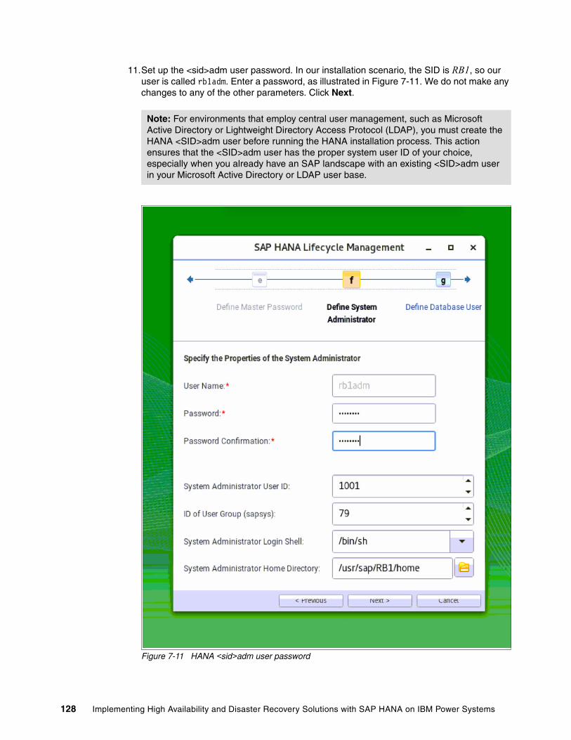
11.Set up the <sid>adm user password. In our installation scenario, the SID is RB1, so our user is called rb1adm. Enter a password, as illustrated in Figure 7-11. We do not make any changes to any of the other parameters. Click Next.
Figure 7-11 HANA <sid>adm user password
Note: For environments that employ central user management, such as Microsoft Active Directory or Lightweight Directory Access Protocol (LDAP), you must create the HANA <SID>adm user before running the HANA installation process. This action ensures that the <SID>adm user has the proper system user ID of your choice, especially when you already have an SAP landscape with an existing <SID>adm user in your Microsoft Active Directory or LDAP user base.
128 Implementing High Availability and Disaster Recovery Solutions with SAP HANA on IBM Power Systems

12.Define the password for the database (DB) SYSTEM user, as depicted in Figure 7-12.
Figure 7-12 Defining the SYSTEM user password
Chapter 7. SAP HANA software stack installation for a scale-up scenario 129
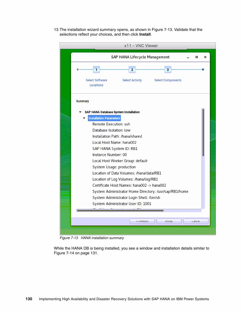
13.The installation wizard summary opens, as shown in Figure 7-13. Validate that the selections reflect your choices, and then click Install.
Figure 7-13 HANA installation summary
While the HANA DB is being installed, you see a window and installation details similar to Figure 7-14 on page 131.
130 Implementing High Availability and Disaster Recovery Solutions with SAP HANA on IBM Power Systems

Figure 7-14 HANA system installation progress
When the installation finishes, your HANA DB is installed, running, and fully functional. To set up your HANA Studio connection to your newly installed HANA system, go to 7.3, “Postinstallation notes” on page 135.
7.2.2 Text-mode installation
To start a text-mode installation, you must run the hdblcm command in the DATA_UNITS/HDB_LCM_LINUX_PPC64LE directory of the folder where you decompressed the HANA installer. This command starts the Life Cycle Manager that is installed as a text-mode wizard that collects your input to drive the installation. All that you need to do is to provide the required information. Except for the SID, instance number, and passwords, all other provided information is standard. The default inputs are between brackets [ ].
Chapter 7. SAP HANA software stack installation for a scale-up scenario 131

Example 7-3 shows the entire text mode installation process, where all of the user inputs are displayed in bold. Ensure that you select the server, client components, and any other options that your environment requires. The installer can be used to add additional components if required.
Also, because this is a scale-up installation, answer no to the question where it asks you if you want to add more hosts to the system.
Example 7-3 HANA text mode installation
hana002:/tmp/hana20_sps1/51052031/DATA_UNITS/HDB_LCM_LINUX_PPC64LE # ./hdblcm
SAP HANA Lifecycle Management - SAP HANA Database 2.00.010.00.1491294693************************************************************************
Scanning Software Locations...Detected components: SAP HANA Database (2.00.010.00.1491294693) in /tmp/51052031/DATA_UNITS/HDB_SERVER_LINUX_PPC64LE/server SAP HANA AFL (incl.PAL,BFL,OFL,HIE) (2.00.010.0000.1491308763) in /tmp/51052031/DATA_UNITS/HDB_AFL_LINUX_PPC64LE/packages SAP HANA EPM-MDS (2.00.010.0000.1491308763) in /tmp/51052031/DATA_UNITS/SAP_HANA_EPM-MDS_10/packages SAP HANA Database Client (2.1.37.1490890836) in /tmp/51052031/DATA_UNITS/HDB_CLIENT_LINUX_PPC64LE/client SAP HANA Smart Data Access (2.00.0.000.0) in /tmp/51052031/DATA_UNITS/SAP_HANA_SDA_20_LINUX_PPC64LE/packages SAP HANA XS Advanced Runtime (1.0.55.288028) in /tmp/51052031/DATA_UNITS/XSA_RT_10_LINUX_PPC64/packages GUI for HALM for XSA (including product installer) Version 1 (1.11.3) in /tmp/51052031/DATA_UNITS/XSA_CONTENT_10/XSACALMPIUI11_3.zip XSAC FILEPROCESSOR 1.0 (1.000.1) in /tmp/51052031/DATA_UNITS/XSA_CONTENT_10/XSACFILEPROC00_1.zip SAP HANA tools for accessing catalog content, data preview, SQL console, etc. (2.001.3) in /tmp/51052031/DATA_UNITS/XSAC_HRTT_20/XSACHRTT01_3.zip XS Monitoring 1 (1.004.0) in /tmp/51052031/DATA_UNITS/XSA_CONTENT_10/XSACMONITORING04_0.ZIP Develop and run portal services for custome apps on XSA (1.001.0) in /tmp/51052031/DATA_UNITS/XSA_CONTENT_10/XSACPORTALSERV01_0.zip SAP Web IDE Web Client (4.001.0) in /tmp/51052031/DATA_UNITS/XSAC_SAP_WEB_IDE_20/XSACSAPWEBIDE01_0.zip XS Services 1 (1.004.2) in /tmp/51052031/DATA_UNITS/XSA_CONTENT_10/XSACSERVICES04_2.ZIP SAPUI5 FESV3 XSA 1 - SAPUI5 SDK 1.44 (1.044.10) in /tmp/51052031/DATA_UNITS/XSA_CONTENT_10/XSACUI5FESV344_10.zip XSAC XMLA Interface For Hana 1 (1.000.1) in /tmp/51052031/DATA_UNITS/XSA_CONTENT_10/XSACXMLAINT00_1.zip Xsa Cockpit 1 (1.000.0) in /tmp/51052031/DATA_UNITS/XSA_CONTENT_10/XSACXSACOCKPIT00_0.zip
Choose an action
Index | Action | Description ----------------------------------------------- 1 | install | Install new system 2 | extract_components | Extract components
132 Implementing High Availability and Disaster Recovery Solutions with SAP HANA on IBM Power Systems

3 | Exit (do nothing) |
Enter selected action index [3]: 1
SAP HANA Database version '2.00.010.00.1491294693' will be installed.
Select additional components for installation:
Index | Components | Description ---------------------------------------------------------------------------------- 1 | server | No additional components 2 | all | All components 3 | afl | Install SAP HANA AFL (incl.PAL,BFL,OFL,HIE) version 2.00.010.0000.1491308763 4 | client | Install SAP HANA Database Client version 2.1.37.1490890836 5 | smartda | Install SAP HANA Smart Data Access version 2.00.0.000.0 6 | xs | Install SAP HANA XS Advanced Runtime version 1.0.55.288028 7 | epmmds | Install SAP HANA EPM-MDS version 2.00.010.0000.1491308763
Enter comma-separated list of the selected indices [4]: 1,4Enter Installation Path [/hana/shared]: Enter Local Host Name [hana002]: Do you want to add hosts to the system? (y/n) [n]: Enter SAP HANA System ID: RB1Enter Instance Number [00]: 00Enter Local Host Worker Group [default]:
Index | System Usage | Description ------------------------------------------------------------------------------- 1 | production | System is used in a production environment 2 | test | System is used for testing, not production 3 | development | System is used for development, not production 4 | custom | System usage is neither production, test nor development
Select System Usage / Enter Index [4]: 1Enter Location of Data Volumes [/hana/data/RB1]: Enter Location of Log Volumes [/hana/log/RB1]: Enter Certificate Host Name For Host 'hana002' [hana002]: Enter SAP Host Agent User (sapadm) Password: ********Confirm SAP Host Agent User (sapadm) Password: ********Enter System Administrator (rb1adm) Password: ********Confirm System Administrator (rb1adm) Password: ********Enter System Administrator Home Directory [/usr/sap/RB1/home]: Enter System Administrator Login Shell [/bin/sh]: Enter System Administrator User ID [1001]: Enter ID of User Group (sapsys) [79]: Enter Database User (SYSTEM) Password: ********Confirm Database User (SYSTEM) Password: ********Restart system after machine reboot? [n]:
Summary before execution:=========================
SAP HANA Database System Installation
Chapter 7. SAP HANA software stack installation for a scale-up scenario 133

Installation Parameters Remote Execution: ssh Database Isolation: low Installation Path: /hana/shared Local Host Name: hana002 SAP HANA System ID: RB1 Instance Number: 00 Local Host Worker Group: default System Usage: production Location of Data Volumes: /hana/data/RB1 Location of Log Volumes: /hana/log/RB1 Certificate Host Names: hana002 -> hana002 System Administrator Home Directory: /usr/sap/RB1/home System Administrator Login Shell: /bin/sh System Administrator User ID: 1001 ID of User Group (sapsys): 79 SAP HANA Database Client Installation Path: /hana/shared/RB1/hdbclient Software Components SAP HANA Database Install version 2.00.010.00.1491294693 Location: /tmp/51052031/DATA_UNITS/HDB_SERVER_LINUX_PPC64LE/server SAP HANA AFL (incl.PAL,BFL,OFL,HIE) Do not install SAP HANA EPM-MDS Do not install SAP HANA Database Client Install version 2.1.37.1490890836 Location: /tmp/51052031/DATA_UNITS/HDB_CLIENT_LINUX_PPC64LE/client SAP HANA Smart Data Access Do not install SAP HANA XS Advanced Runtime Do not install
Do you want to continue? (y/n): y
Installing components...Installing SAP HANA Database...
[ ... Cropped ... ]
Creating Component List...SAP HANA Database System installedYou can send feedback to SAP with this form: https://hana002:1129/lmsl/HDBLCM/RB1/feedback/feedback.htmlLog file written to '/var/tmp/hdb_RB1_hdblcm_install_2017-07-04_14.13.04/hdblcm.log' on host 'hana002'.
At this point, your HANA DB is installed, running, and fully functional.
134 Implementing High Availability and Disaster Recovery Solutions with SAP HANA on IBM Power Systems

7.3 Postinstallation notes
After you have installed HANA on your system, this section shows useful information to help you get started accessing and managing your DB.
First, you must install HANA Studio on your workstation. The installer is inside the DATA_UNITS/HDB_STUDIO_<platform> folder in your HANA system. Use an SCP client to copy the folder corresponding to your workstation architecture and install the software on your workstation. In our case, we use the MacOS 64-bit version of HANA Studio.
After installation, when you open HANA Studio on your workstation, you see a window similar to Figure 7-15. Add a connection to your newly installed HANA instance by using the Add System button on the left side of the Systems navigation tab, as depicted by the red arrow that is shown in Figure 7-15.
Figure 7-15 HANA Studio console: Adding a system
Chapter 7. SAP HANA software stack installation for a scale-up scenario 135

Input the required information, as shown in Figure 7-16. If your HANA environment is already registered in your DNS server, use the host name to complete the information that is depicted as 1 in the figure; otherwise, use the IP address. Complete the instance number information for 2. Starting with HANA 2.0 SPS1, all systems are multi-tenant, so make the proper selection as described by 3 and use the SYSTEM DB user to connect to the DB, as shown by 4. Give it a proper description, as outlined by 5, and click Next.
Figure 7-16 HANA Studio: Information to add a HANA instance
Note: When you add System to HANA, you must select Multiple containers because HANA V2.0 sps01 uses Multiple containers DB mode. Otherwise, you see the following error message.
1
2
3
4
5
136 Implementing High Availability and Disaster Recovery Solutions with SAP HANA on IBM Power Systems

Configure your connection to the DB by using the SYSTEM user and its password, as shown in Figure 7-17. Click Finish to complete this setup.
Figure 7-17 HANA Studio: Connecting to the HANA instance
Chapter 7. SAP HANA software stack installation for a scale-up scenario 137

After completion, double-click your instance entry on the left side of the Systems navigation menu to open its properties, as shown in Figure 7-18. Go to the Landscape tab of your instance to validate that all services are running.
Figure 7-18 HANA Studio: Checking the Landscape tab of your HANA system
You now have full control of your HANA system. From within the HANA Studio interface, you can take backups of your instance, configure SAP HSR, change the configuration of the DB parameters, and much more.
For a complete guide about how to manage a HANA DB, see SAP HANA Administration Guide.
If you are planning to configure HSR between two scale-up systems, or configuring high availability (HA) with the SUSE HA Extension, see Chapter 9, “SAP HANA Systems Replication for high availability and disaster recovery scenarios” on page 149.
Note: It is a preferred practice to now configure the backup strategy of your HANA system.
138 Implementing High Availability and Disaster Recovery Solutions with SAP HANA on IBM Power Systems
Chapter 8. SAP HANA software stack installation for a scale-out scenario
This chapter describes the differences between scale-up and scale-out HANA installations.
This chapter also provides the scale-out prerequisites that you must meet when you plan to use the Storage Connector API for sharing the data and log areas among the cluster nodes.
This chapter includes the following sections:
� Differences between a scale-out and scale-up installations� Installing HANA scale-out clusters� Postinstallation notes
8
© Copyright IBM Corp. 2017. All rights reserved. 139

8.1 Differences between a scale-out and scale-up installations
When installing HANA on a number of scale-out nodes, run the installer on the first node, and then request to add more nodes to the HANA instance. The installer then prompts you for the additional host names and adds the nodes to the existing HANA instance.
The HANA binary files are installed in the /hana/shared directory, which is shared among all the cluster nodes. As such, there is no duplication of the binary files on each node. After installation, each worker node has an entry inside the /hana/data/<SID> and /hana/log/<SID> directories, in the form of mntNNNN, characterizing a cluster-based layout of data and logs.
If you are using a shared storage approach, Elastic Storage Server, or Network File System (NFS), you do not need any special configuration for installing HANA. If you are using the storage connector API, then you must start the installer with a setup file, as described in 8.2.3, “Storage Connector API setup” on page 146.
8.1.1 Prerequisites
Your nodes must comply with the following prerequisites before you start a HANA scale-out installation:
� The date and time of all the nodes must be synchronized. Use a suitable Network Time Protocol (NTP) server to comply with this requirement. If you do not have any NTP server available, one of the nodes can act as one.
� Ensure that all nodes can ping one another by name by using both their short and fully qualified host names.
� A scale-out environment is characterized by a true cluster that is built at the application layer, that is, the HANA database (DB). To ease the management of the cluster, set up password-less communication among the cluster nodes.
8.2 Installing HANA scale-out clusters
Both the graphical and text-mode HANA installations are available for a scale-out installation. The next sections show only the differences in the steps when compared to a scale-up cluster installation.
All our installations use a four-node cluster with three worker nodes (saphana005, hana006, hana007), and one standby node (hana008).
Note: When using a shared storage for the HANA data and log areas, Elastic Storage Server, or NFS, validate that these file systems are mounted on all nodes before installing HANA. If using the storage connector for the data and log areas, check that they are unmounted on all nodes before installing HANA.
The HANA shared file system is mounted for both cases.
140 Implementing High Availability and Disaster Recovery Solutions with SAP HANA on IBM Power Systems
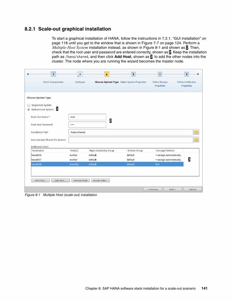
8.2.1 Scale-out graphical installation
To start a graphical installation of HANA, follow the instructions in 7.2.1, “GUI installation” on page 118 until you get to the window that is shown in Figure 7-7 on page 124. Perform a Multiple-Host System installation instead, as shown in Figure 8-1 and shown as 1. Then, check that the root user and password are entered correctly, shown as 2. Keep the installation path as /hana/shared, and then click Add Host, shown as 3, to add the other nodes into the cluster. The node where you are running the wizard becomes the master node.
Figure 8-1 Multiple Host (scale-out) installation
1
2
3
Chapter 8. SAP HANA software stack installation for a scale-out scenario 141

Every time that you click Add Host, a window similar to Figure 8-2 opens. Add one node at a time by using its host name, which is shown by 1, and select the appropriate node role, which is shown by 2. There is no need to change the other parameters.
Figure 8-2 Adding a node to the installation
In our scenario, we have two more worker nodes and one standby node. So, we perform the add-node step three times until we have a layout with all of our nodes, as shown in Figure 8-1 on page 141 and shown by 3.
The remaining of the installation process looks the same as a scale-up installation from this point. You can resume the installation by following the steps from Figure 7-8 on page 125 onward.
8.2.2 Scale-out text-mode installation
To start a text-mode installation of HANA, see 7.2.2, “Text-mode installation” on page 131. The installation flow looks similar to Example 7-3 on page 132, except that you enter yes to the question Do you want to add hosts to the system?. If you do so, you are prompted to add the information that is required for each one of the nodes. The complete installation flow is shown in Example 8-1 with the user inputs in bold.
Example 8-1 Scale-out installation: Text mode
saphana005:/tmp/51052031/DATA_UNITS/HDB_LCM_LINUX_PPC64LE # ./hdblcm
SAP HANA Lifecycle Management - SAP HANA Database 2.00.010.00.1491294693************************************************************************
Scanning Software Locations...Detected components: SAP HANA Database (2.00.010.00.1491294693) in /mnt/SW/HANA/HANA 2.0/SPS01/51052031/DATA_UNITS/HDB_SERVER_LINUX_PPC64LE/server
[... snip ...]
Xsa Cockpit 1 (1.000.0) in /mnt/SW/HANA/HANA 2.0/SPS01/51052031/DATA_UNITS/XSA_CONTENT_10/XSACXSACOCKPIT00_0.zip
Choose an action
Index | Action | Description
1
2
142 Implementing High Availability and Disaster Recovery Solutions with SAP HANA on IBM Power Systems

----------------------------------------------- 1 | install | Install new system 2 | extract_components | Extract components 3 | Exit (do nothing) |
Enter selected action index [3]: 1
SAP HANA Database version '2.00.010.00.1491294693' will be installed.
Select additional components for installation:
Index | Components | Description --------------------------------------------------------------------------------- 1 | server | No additional components 2 | all | All components 3 | afl | Install SAP HANA AFL (incl.PAL,BFL,OFL,HIE) version 2.00.010.0000.1491308763 4 | client | Install SAP HANA Database Client version 2.1.37.1490890836 5 | smartda | Install SAP HANA Smart Data Access version 2.00.0.000.0 6 | xs | Install SAP HANA XS Advanced Runtime version 1.0.55.288028 7 | epmmds | Install SAP HANA EPM-MDS version 2.00.010.0000.1491308763
Enter comma-separated list of the selected indices [4]: 1,4Enter Installation Path [/hana/shared]: Enter Local Host Name [saphana005]: Do you want to add hosts to the system? (y/n) [n]: yEnter comma-separated host names to add: hana006,hana007,hana008Enter Root User Name [root]: Collecting information from host 'hana006'...Collecting information from host 'hana007'...Collecting information from host 'hana008'...Information collected from host 'hana008'.Information collected from host 'hana007'.Information collected from host 'hana006'.
Select roles for host 'hana006':
Index | Host Role | Description ------------------------------------------------------------------- 1 | worker | Database Worker 2 | standby | Database Standby 3 | extended_storage_worker | Dynamic Tiering Worker 4 | extended_storage_standby | Dynamic Tiering Standby 5 | streaming | Smart Data Streaming 6 | rdsync | Remote Data Sync 7 | ets_worker | Accelerator for SAP ASE Worker 8 | ets_standby | Accelerator for SAP ASE Standby 9 | xs_worker | XS Advanced Runtime Worker 10 | xs_standby | XS Advanced Runtime Standby
Enter comma-separated list of selected indices [1]: 1Enter Host Failover Group for host 'hana006' [default]: Enter Storage Partition Number for host 'hana006' [<<assign automatically>>]: Enter Worker Group for host 'hana006' [default]:
Chapter 8. SAP HANA software stack installation for a scale-out scenario 143

Select roles for host 'hana007':
Index | Host Role | Description ------------------------------------------------------------------- 1 | worker | Database Worker 2 | standby | Database Standby 3 | extended_storage_worker | Dynamic Tiering Worker 4 | extended_storage_standby | Dynamic Tiering Standby 5 | streaming | Smart Data Streaming 6 | rdsync | Remote Data Sync 7 | ets_worker | Accelerator for SAP ASE Worker 8 | ets_standby | Accelerator for SAP ASE Standby 9 | xs_worker | XS Advanced Runtime Worker 10 | xs_standby | XS Advanced Runtime Standby
Enter comma-separated list of selected indices [1]: 1Enter Host Failover Group for host 'hana007' [default]: Enter Storage Partition Number for host 'hana007' [<<assign automatically>>]: Enter Worker Group for host 'hana007' [default]:
Select roles for host 'hana008':
Index | Host Role | Description ------------------------------------------------------------------- 1 | worker | Database Worker 2 | standby | Database Standby 3 | extended_storage_worker | Dynamic Tiering Worker 4 | extended_storage_standby | Dynamic Tiering Standby 5 | streaming | Smart Data Streaming 6 | rdsync | Remote Data Sync 7 | ets_worker | Accelerator for SAP ASE Worker 8 | ets_standby | Accelerator for SAP ASE Standby 9 | xs_worker | XS Advanced Runtime Worker 10 | xs_standby | XS Advanced Runtime Standby
Enter comma-separated list of selected indices [1]: 2Enter Host Failover Group for host 'hana008' [default]: Enter Worker Group for host 'hana008' [default]:
Enter SAP HANA System ID: RB1Enter Instance Number [00]: 13Enter Local Host Worker Group [default]:
Index | System Usage | Description ------------------------------------------------------------------------------- 1 | production | System is used in a production environment 2 | test | System is used for testing, not production 3 | development | System is used for development, not production 4 | custom | System usage is neither production, test nor development
Select System Usage / Enter Index [4]: 2Enter Location of Data Volumes [/hana/data/RB1]: Enter Location of Log Volumes [/hana/log/RB1]: Restrict maximum memory allocation? [n]:
144 Implementing High Availability and Disaster Recovery Solutions with SAP HANA on IBM Power Systems

Enter Certificate Host Name For Host 'saphana005' [saphana005]: Enter Certificate Host Name For Host 'hana006' [hana006]: Enter Certificate Host Name For Host 'hana007' [hana007]: Enter Certificate Host Name For Host 'hana008' [hana008]: Enter System Administrator (rb1adm) Password: ********Confirm System Administrator (rb1adm) Password: ********Enter System Administrator Home Directory [/usr/sap/RB1/home]: Enter System Administrator Login Shell [/bin/sh]: Enter System Administrator User ID [1001]: Enter Database User (SYSTEM) Password: ********Confirm Database User (SYSTEM) Password: ********Restart system after machine reboot? [n]:
Summary before execution:=========================
SAP HANA Database System Installation Installation Parameters Remote Execution: ssh Database Isolation: low
[ ... snip ...]
Additional Hosts hana008 Role: Database Standby (standby) High-Availability Group: default Worker Group: default Storage Partition: N/A hana007 Role: Database Worker (worker) High-Availability Group: default Worker Group: default Storage Partition: <<assign automatically>> hana006 Role: Database Worker (worker) High-Availability Group: default Worker Group: default Storage Partition: <<assign automatically>>
Do you want to continue? (y/n): y
Installing components...Installing SAP HANA Database... Preparing package 'Saphostagent Setup'...
[ ... snip ...]
Updating SAP HANA Database instance integration on host 'hana008'...Creating Component List...SAP HANA Database System installedYou can send feedback to SAP with this form: https://saphana005:1129/lmsl/HDBLCM/RB1/feedback/feedback.html
Chapter 8. SAP HANA software stack installation for a scale-out scenario 145

Log file written to '/var/tmp/hdb_RB1_hdblcm_install_2017-07-11_21.57.20/hdblcm.log' on host 'saphana005'.
8.2.3 Storage Connector API setup
There is more than one method to use the storage connector API. In this publication, we use a logical volume manager (LVM) -based one that is called hdb_ha.fcClientLVM. For more information and to check how to use a different storage connector, see SAP HANA Fibre Channel Storage Connector Admin Guide.
Complete the following steps:
1. To use the storage connector during a scale-out installation, you must create a text file that is used as the initial input to what will be part of the HANA instance global.ini configuration file. This text file provides instructions about the storage connector about how to map the volume groups (VGs) and logical volumes (LVs) that you created in “Storage Connector API for the data and log areas” on page 82.
Example 8-2 shows a global.ini file that works for our four-node cluster, with one master node, two worker nodes, and one standby node. The file system layout that we use is the one that is described in “Storage Connector API for the data and log areas” on page 82. Create this file in the /hana/shared directory so that all nodes have access to it.
Example 8-2 A global.ini file to be used at installation time for using the LVM storage connector
# cat /hana/shared/global.ini[storage]ha_provider = hdb_ha.fcClientLVMpartition_1_data__lvmname = hanadata01-datalv01partition_1_log__lvmname = hanalog01-loglv01partition_2_data__lvmname = hanadata02-datalv02partition_2_log__lvmname = hanalog02-loglv02partition_3_data__lvmname = hanadata03-datalv03partition_3_log__lvmname = hanalog03-loglv03
partition_*_*__prtype = 5partition_*_*__mountoptions = -t xfs
2. Call the installer by using the parameter --storage_cfg=<global.ini directory>, where the input is the path to the directory that contains the global.ini file (not the path to the file itself), which is /hana/shared, as shown in Example 8-2.
To check how to start the graphical installer, see Figure 7-3 on page 120. Start it by running the following command:
./hdblcmgui --storage_cfg=/hana/shared
3. Follow the guidelines in 8.2.1, “Scale-out graphical installation” on page 141 to proceed with the installation.
Similarly, if you want to install HANA by using the text-mode installer, go to the HDB_LCM_LINUX_PPC64LE folder, as explained in Example 7-3 on page 132, and run the following command:
./hdblcm --storage_cfg=/hana/shared
4. Follow the guidelines in 8.2.2, “Scale-out text-mode installation” on page 142 to proceed with the installation.
146 Implementing High Availability and Disaster Recovery Solutions with SAP HANA on IBM Power Systems

8.3 Postinstallation notes
After installing HANA on the scale-out cluster, you can connect to it by using the HANA Studio interface. The process for adding the HANA instance is the same as outlined in 7.3, “Postinstallation notes” on page 135. When you add the instance, use the master node of your cluster (the one you from which you ran the installation) as the node to which to connect.
After adding the instance in HANA Studio, go to the Landscape → Services tab to confirm that the services are distributed among all the nodes, as shown in Figure 8-3.
Figure 8-3 Scale-out instance in HANA Studio
Note: When you add System to HANA, you must select Multiple containers because HANA V2.0 sps01 uses multiple containers DB mode. Otherwise, you see the following error message.
Chapter 8. SAP HANA software stack installation for a scale-out scenario 147

Also, review the Landscape → Hosts tab, as shown in Figure 8-4. Node hana008 is displayed as STANDBY for the services for our installation.
Figure 8-4 Scale-out system: Current node roles
As a preferred practice, perform fail-over tests by shutting down the HANA service in one of the worker nodes, or shut down the node, and observe that the standby node takes over its role as a must to open a HANA Studio connection to another node that is running to check the cluster status.
Note: A scale-out cluster can handle only as many simultaneous node outages as the number of standby nodes in the cluster. For example, if you have only one standby node, you can sustain an outage of a single node. If two nodes fail at the same time, your HANA DB is brought offline. If you must protect your business against the failure of multiple nodes at the same time, add as many standby nodes as you need.
148 Implementing High Availability and Disaster Recovery Solutions with SAP HANA on IBM Power Systems

Chapter 9. SAP HANA Systems Replication for high availability and disaster recovery scenarios
This chapter introduces the concepts of SAP HANA Systems Replication (HSR), which is a feature included in HANA and can be used for replicating data between HANA systems.
This chapter also provides a step-by-step description of how to set up HSR and perform some simple tests before you place HSR into production.
This chapter includes the following sections:
� SAP HANA Systems Replication overview� Implementing HSR� HSR and takeover tests
9
© Copyright IBM Corp. 2017. All rights reserved. 149
9.1 SAP HANA Systems Replication overview
Having a well-configured system running on reliable hardware is a good start, but it does not protect you against hardware failures, software bugs, or human errors. Day-to-day operations are great if you have no system failures, but the price to pay when it fails is too high if you have not prepared for that moment.
The last line of defense against systems loss is the backup. If all other contingency strategies fail, restoring from backup is the solution. The problems of pure backup-based contingency strategies, though, are its high recovery time objective (RTO) and recovery point objective (RPO) metrics. It might take too much time to restore a backup, time that your business cannot afford to be offline. On the data side, depending on your backup strategy, your last backup might not contain all the data that you lost, which is why computer systems can be built with contingencies at various component layers, hardware and software, to ensure continuous operations.
The level of continuous operation that a contingency solution provides is the metric that is used to validate it as an acceptable solution to the business. There is no better or worse high availability (HA) solution for a system. There are solutions that meet the business requirements and others that do not. It is up to you to validate which ones are suitable for your business. The higher the continuous operation levels your business requires, the higher the cost of the solution, given the use of more sophisticated technologies.
SAP HSR is a contingency solution that is used to duplicate your HANA database (DB), which means that it uses a different system (that is, another operating system (OS) instance), a different set of disks, and a different DB instance than the primary ones. In summary, it is based on having two independent HANA environments host the same data. The data is created on the primary system and replicated to the secondary system over the network through TCP/IP. If a failure of the primary system occurs, you can choose to have the secondary one take over.
Section 1.3, “High availability for HANA” on page 3 describes the HA scenarios in this publication. SAP HSR is the SAP base technology for a HANA disaster recovery (DR) implementation. Figure 1-2 on page 5 shows two data centers where the primary HANA instance replicates its data to the secondary one at a different data center. This concept can also be applied to two DBs instances in the same data center, in which this configuration is closer to being called a HA solution. Additionally, you can create a 3-tier replication strategy, where the primary system replicates to the secondary one, and the secondary to a third one, thus creating a cascading relationship. This strategy is useful when you have HA between two systems on your production site, and a third system at your DR site.
Let us now look at how replication works so that you have an idea of how the available methodologies work, and so that you can choose which one to apply to your systems based on your business requirements.
Note: HSR takeover operations, without the assistance of additional software such as SUSE HA Extension, is a manual operation. You can automate the process, but triggering the takeover still is a manual operation. If your business must perform automated takeover operations with a more aggressive RTO, then in addition to this chapter, read Chapter 10, “SUSE high availability configuration for a two-node high availability scenario” on page 165.
150 Implementing High Availability and Disaster Recovery Solutions with SAP HANA on IBM Power Systems

9.1.1 SAP HANA System Replication methods
SAP HSR has two fundamental concepts that you must understand:
� The replication mode: Either synchronous to memory, synchronous, synchronous with full sync option, or asynchronous.
� The operation mode: Either delta shipping, log replay, or log replay with read access.
This section explains these two concepts in more detail.
HSR replication modeThe HSR replication mode determines the behavior of the secondary system in terms of acquiring the data from the primary system and having it ready for use.
One of the four replication modes is the asynchronous mode, in which the primary system sends the data to the secondary one but does not wait for the secondary to acknowledge it. In this manner, commit operations on the primary node do not require an acknowledgment from the secondary one, which does not delay the overall process for creating or modifying data on the primary system. However, an asynchronous operation means that your RPO is nonzero. To achieve zero data loss, you must use synchronous replication, usually done between systems at the same site. Nevertheless, the asynchronous replication mode is the only alternative for replicating data between distant data centers, as making it synchronous in this case adds too much latency to commit operations in the primary site.
For the synchronous mode, all data that is created or modified on the primary system is sent to the secondary system, and commit operations must wait until the secondary system replies that the data is safely stored on its disks. This process ensures an RPO of zero, but adds latency to all write operations. If you choose to replicate data by using this mode, your systems must adhere to the file system key performance indicators (KPIs) in which the maximum latency for log writing is 1000 μs. In essence, the network connection between your two systems must provide a low latency to enable this setup.
Another mode is the synchronous in-memory, where replication also happens synchronously, but the commit is granted after the replicated data is stored onto the secondary node’s memory. After that, the secondary node makes this data persistent on its disks. As the memory of the secondary system is already loaded with data, the takeover is much faster.
The last mode is the synchronous with full sync option, which requires the secondary node to be online and receiving the replicated data. If the secondary node goes offline, all transactions on the primary node are suspended until the secondary node comes back online.
HSR operation modeThe HSR operation mode determines how the data is sent and processed by the secondary system.
The delta shipping mode (delta_shipping) is the classic mode, and it works by shipping all of the modified data to the secondary system every 10 minutes by default. During these 10-minute intervals, the redo-logs are shipped to the secondary system. So, when a failure of the primary node occurs, the secondary processes the redo-logs since the last delta shipping point.
In the log replay mode (logreplay), only the redo-logs are sent over to the secondary system, and they are immediately replayed. This mode makes the transfer lighter in terms of network consumption, and also makes the takeover operations faster.
Chapter 9. SAP HANA Systems Replication for high availability and disaster recovery scenarios 151

The log replay with read access mode (logreplay_readaccess) works in a similar fashion to the log replay mode, except that it also enables the receiver to operate in read-only mode, so you can query the DB with proper SQL statements.
9.1.2 HSR requirements
There are a few systems requirements that you must meet before you start the configuration of HSR:
� All participating hosts must be able to ping each other by name, either by having the DNS server resolve the information or by using local /etc/hosts entries.
� The date and time of all participating hosts must be synchronized with a Network Time Protocol (NTP) server. If you do not have any suitable NTP server in your network, choose one of the hosts to act as one, and have all the others hosts synchronize their time with it.
� Both HANA systems must have the same SID and instance number. Also, the next instance number must be available on both systems, that is, if you use instance number 00, then 01 is also available. Host names can be different (a virtual IP and host name are defined when using HSR with SUSE HA Extension, as described in Chapter 10, “SUSE high availability configuration for a two-node high availability scenario” on page 165).
� Both HANA instances that take part in the replication must have a current backup. If you have not implemented a backup strategy, take a file-based backup from HANA Studio as a temporary solution.
� The systemPKI SSFS data and key must be exchanged between the two systems, otherwise the secondary system cannot be registered for the replication. This is a new requirement for HSR starting with HANA V2.0.
� The secondary HANA system must be turned off before configuring it to replicate data from the primary system.
You can use an isolated network or VLAN with HSR. It is not mandatory, but it is a preferred practice to avoid having the replication network traffic compete with the data traffic on the same logical network interface. If you decide to follow this preferred practice, see “Using a dedicated network for HSR” because there are some extra configuration steps that you must make to your HANA instances global.ini profile.
152 Implementing High Availability and Disaster Recovery Solutions with SAP HANA on IBM Power Systems

Using a dedicated network for HSRThe primary network for HANA is the data network through which the application servers access the DB. When you use a secondary network to handle HSR, your network layout looks similar to Figure 9-1, where HSR is set up between two scale-up systems on the same site.
Figure 9-1 HANA environment with a separate network for HSR
In our implementation, the 10.10.12.0/24 network is used by our hosts for data traffic, and for communicating with the external world. The 192.168.1.0/24 network is defined for HSR. Example 9-1 illustrates how our /etc/hosts file is configured to meet the second requirement in 9.1.2, “HSR requirements” on page 152. Note the sections in bold with the definitions for the IP addresses for the data and replication networks.
Example 9-1 The /etc/hosts file from host hana002
# IP-Address Full-Qualified-Hostname Short-Hostname
127.0.0.1 localhost
# special IPv6 addresses::1 localhost ipv6-localhost ipv6-loopback
fe00::0 ipv6-localnet
ff00::0 ipv6-mcastprefixff02::1 ipv6-allnodesff02::2 ipv6-allroutersff02::3 ipv6-allhosts
#Data network - RB1 hosts10.10.12.81 hana002.pok.stglabs.ibm.com hana00210.10.12.82 hana003.pok.stglabs.ibm.com hana003
#HSR network - RB1 hosts
192.168.1.81 hana002-rep.pok.stglabs.ibm.com hana002-rep192.168.1.82 hana003-rep.pok.stglabs.ibm.com hana003-rep
HANA A HANA B
App serversUsers
HSR Network
HSR Network
Data Network
Data Network
Chapter 9. SAP HANA Systems Replication for high availability and disaster recovery scenarios 153

When configuring HSR, you must use the host name of the system to create the replication scheme. However, the host names of the systems are always bound to the primary interface that is used for data traffic. So, if you do not explicitly instruct HANA to use the replication interface with HSR, it ends up using the data network.
All HANA instances have a global.ini configuration file. There are many parameters that can be changed within this file. To instruct HANA to use the replication interface with HSR, you must edit the following file:
/hana/shared/<SID>/exe/linuxppc64le/HDB_<HANA version>/config/global.ini
Open this file by using your favorite text editor and look for a section named “[system_replication_hostname_resolution]”, as shown in Example 9-2. It is empty when you first view it, and then you add the lines for your hosts, as shown by the highlights 1 and 2. These are the entries that instruct HANA to use the IP addresses in the 192.168.1.0/24 network for HSR, and still able to use the systems host name for replication.
Example 9-2 Configuring the global.ini file to use a dedicated replication network for HSR
[... cropped ...]# .short_desc# specifies the resolution of remote site hostnames to addresses for system replication# .full_desc# specifies the resolution of remote site hostnames to addresses for system replication.# for multi-tier replication only the direct neighbors must be specified# Format: ipaddress = internal hostname# e. g. 192.168.100.1 = hanahost01[system_replication_hostname_resolution]192.168.1.81=hana002 1192.168.1.82=hana003 2## .short_desc# Configuration of system replication communication settings# .full_desc# This section contains parameters that are related to configuration# of various system replication communication settings.[system_replication_communication]
# .short_desc# the network interface the processes shall listen on, if system replication is enabled.# .full_desc## Possible values are:# - .global: all interfaceslisteninterface = .global 3[... cropped ...]
Also, check that the listeninterface parameter is set to .global inside the section [system_replication_communication], as shown in Example 9-2 and depicted by 3.
154 Implementing High Availability and Disaster Recovery Solutions with SAP HANA on IBM Power Systems

9.2 Implementing HSR
This section illustrates how to replicate data between two scale-up systems. Both systems already meet the three requirements that are described in 9.1.2, “HSR requirements” on page 152. Complete the following steps:
1. You must take a backup. Considering that we are using an ordinary lab environment that contains no data inside the DB, we take a file-based backup. To do so, right-click your HANA instance inside HANA Studio and go through the menu to trigger a backup of the SYSTEM DB, as shown in Figure 9-2. This action opens a wizard that defaults to taking a file-based backup if you do not change any of its predefined parameters. Create the backup and proceed. Then, back up your SID tenant DB by repeating the process, but instead choose Back Up Tenant Database, as shown in Figure 9-2. Back up both the source and destination systems, which take part in the replication setup.
Figure 9-2 Backing up the HANA instance
2. Get the systemPKI, the SSFS data, and key from the source system and copy them to the secondary system. The locations where these files are kept are:
– /hana/shared/<SID>/global/security/rsecssfs/data/SSFS_<SID>.DAT
– /hana/shared/<SID>/global/security/rsecssfs/key/SSFS_<SID>.KEY
Example 9-3 shows how to perform these operations. In our example, we are logged on one of the servers (hana002) and copy the files over to the other server (hana003).
Example 9-3 Exchanging the systemPKI SSFS data and key files
hana002:/ # cd /hana/shared/RB1/global/security/rsecssfshana002:/hana/shared/RB1/global/security/rsecssfs # lsdata keyhana002:/hana/shared/RB1/global/security/rsecssfs # scp data/SSFS_RB1.DAT \ root@hana003:/hana/shared/RB1/global/security/rsecssfs/data/Password: SSFS_RB1.DAT 100% 2960 2.9KB/s 00:00 hana002:/hana/shared/RB1/global/security/rsecssfs # scp key/SSFS_RB1.KEY \ root@hana003:/hana/shared/RB1/global/security/rsecssfs/key
Special consideration: You must be careful when you change the value of the listeninterface parameter that is under the [system_replication_communication] section because there are two different listeninterface parameters in that file, and the other one has nothing to do with HSR.
Chapter 9. SAP HANA Systems Replication for high availability and disaster recovery scenarios 155

Password: SSFS_RB1.KEY 100% 187 0.2KB/s 00:00
3. Enable replication on the source system. Avoid calling the system’s primary and secondary because their roles are interchangeable as you perform takeovers. This is why we described them as source and destination, which is really how SAP refers to them in its replication wizard.
4. Enable HSR on the source system by right-clicking the source system in the HANA Studio and go to the menu shown in Figure 9-3.
Figure 9-3 Enabling HSR on the source system
156 Implementing High Availability and Disaster Recovery Solutions with SAP HANA on IBM Power Systems

5. Enable System Replication, as shown in Figure 9-4. All other options are disabled because they are not applicable to a source system that is being set up for replication. Click Next.
Figure 9-4 Enabling System Replication
Chapter 9. SAP HANA Systems Replication for high availability and disaster recovery scenarios 157

6. Assign your source system a Primary System Logical Name, as shown in Figure 9-5. This parameter is also known as the site name, and the HANA Studio HSR status information under the Landscape → System Replication tab refers to it as site name. In our example, we decide to name this first system MONTANA. Good choices are names that relate to the physical location of your system, such as data center locations or building names.
Figure 9-5 Assigning a primary system logical name
That is all there is to setting up the source system for HSR. Let us now set up the destination system. The destination instance must be shut down.
158 Implementing High Availability and Disaster Recovery Solutions with SAP HANA on IBM Power Systems
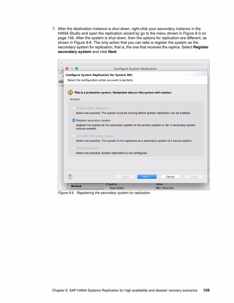
7. After the destination instance is shut down, right-click your secondary instance in the HANA Studio and open the replication wizard by go to the menu shown in Figure 9-3 on page 156. After the system is shut down, then the options for replication are different, as shown in Figure 9-6. The only action that you can take is register the system as the secondary system for replication, that is, the one that receives the replica. Select Register secondary system and click Next.
Figure 9-6 Registering the secondary system for replication
Chapter 9. SAP HANA Systems Replication for high availability and disaster recovery scenarios 159

8. Set the Secondary System Logical name and the replication parameters for replication mode and operation mode. In our example, we use CYRUS as the secondary system logical name (or site name), as shown by 1 in Figure 9-7. We choose to replicate it synchronously, as shown by 2. The operation mode that we choose is log replay, as shown by 3. Also, we make this destination system point to the source one to get the data, as shown by 4, by using the host name and HANA DB instance number of the source system. Click Finish to complete the wizard.
Figure 9-7 Choosing the replication parameters
123
4
160 Implementing High Availability and Disaster Recovery Solutions with SAP HANA on IBM Power Systems

9. The destination system starts in replication mode. You can check that the replication is running by double-clicking the source instance in the HANA Studio to open its properties, and then selecting Landscape → System Replication, as shown in Figure 9-8. Check all entries that are marked as ACTIVE in the column REPLICATION_STATUS.
Figure 9-8 Synchronized HANA Systems Replication
9.3 HSR and takeover tests
This section explains how to perform takeovers between two HANA systems by using System Replication. The next sections instruct you about how to create a simple table, add it, and then list an entry in it.
The following sections assume that your HSR is configured and synchronized.
Chapter 9. SAP HANA Systems Replication for high availability and disaster recovery scenarios 161

9.3.1 Creating a test table and populating it
To create a table in your HANA DB, complete the following steps:
1. Open the SQL console inside HANA Studio, as shown in Figure 9-9, by right-clicking your HANA instance and go to the Open SQL Console menu entry.
Figure 9-9 Opening the HANA instance SQL console
2. After the SQL console opens, use the SQL statements in Example 9-4 to create a table, populate it with one entry, and then query its contents. You can run one command at a time, or paste them all, one per line, and run them together. To run an SQL statement in the SQL console, use the F8 key or the Execute button on the upper right of the console.
Example 9-4 Creating some data with SQL statements
CREATE TABLE RESIDENCY (NAME CHAR(20), CITY CHAR (20) )
INSERT INTO RESIDENCY (NAME, CITY) VALUES ('hana', 'montana')
SELECT * FROM RESIDENCY
162 Implementing High Availability and Disaster Recovery Solutions with SAP HANA on IBM Power Systems

After running the three commands, the result of the SELECT statement displays an output similar to the one that is shown in Figure 9-10.
Figure 9-10 Querying a created entry by using SQL statements
9.3.2 Performing a takeover
Now that you have some data to validate a takeover, shut down the source system and initiate the takeover by right-clicking the destination system and selecting the Configure System Replication menu entry, as shown in Figure 9-3 on page 156. Choose the Perform takeover action, as shown in Figure 9-4 on page 157.
You do not have to change any of the parameters. The host and instance numbers are automatically input. Click Finish to proceed, as shown in Figure 9-11.
Figure 9-11 HANA System Replication: Takeover to the destination HANA instance
Chapter 9. SAP HANA Systems Replication for high availability and disaster recovery scenarios 163
The takeover operation brings the destination system to its full active state, and you can now connect to its DB and perform queries. A takeover does not shut down the DB on the source system in case of a controlled test, so applications can still send operations to it. You can take precautions to avoid applications from continuing to use the DB still running on the source system.
We encourage you to open the destination system SQL console, as explained in 9.3.1, “Creating a test table and populating it” on page 162 and running the SELECT statement from Example 9-4 on page 162. If you can see the created entry in the test table in your destination system, this means that the replication is working properly.
164 Implementing High Availability and Disaster Recovery Solutions with SAP HANA on IBM Power Systems

Chapter 10. SUSE high availability configuration for a two-node high availability scenario
This chapter describes the configuration and maintenance of a simple two-node cluster that uses SUSE Linux Enterprise Server V12 High Availability Extension and the SAP HANA system resource agents. This chapter describes prerequisites, hardware requirements, and the use of the High Availability Web Konsole (HAWK), and includes a detailed step-by-step guide about how to set up the cluster from scratch.
As with all clusters, this cluster must be thoroughly tested before going into production. Some test scenarios can be found in the SAP HANA SR Performance Optimized Scenario for SUSE Linux Enterprise Server for SAP Applications V12 SP1 Guide.
This chapter contains the following sections:
� Assumptions� Shoot The Other Node In The Head� Stopping SAP HANA� Watchdog� The ha-cluster-init process� Checking the cluster status� The ha-cluster-join command� Updating the cluster configuration� HAWK SAP HANA configuration� Maintenance� Further reading
10
Note: If you are planning to use Live Partition Mobility (LPM) on HANA, we do not recommend it for cluster or stand-alone large instances because of possible timeouts that can happen to the logical partition (LPAR) that is being moved and the consequences that can have on a running cluster. Although the team did not test the LPM on HANA feature, the timeouts due to these cluster configurations can potentially disrupt the running cluster.
© Copyright IBM Corp. 2017. All rights reserved. 165

10.1 Assumptions
This chapter has two servers that are divided across two sites, as shown in Table 10-1.
Table 10-1 Location and hosts
There is only a single IP network, but in a production environment, you must have at least two networks. If there are two networks, configure the additional corosync ring. This can be configured by using the YaST interface, as described in 10.8, “Updating the cluster configuration” on page 179.
10.1.1 System replication
Ensure that SAP HANA System Replication is configured and running correctly by using the HANA Studio client or the command line, which are shown in Figure 10-1 and in Example 10-1.
Figure 10-1 System replication status by using SAP HANA Studio
Example 10-1 Checking the system replication status by using hdbnsrutil
hana002:~ # su - rb1admrrb1adm@hana002:/usr/sap/RB1/HDB00> hdbnsutil -sr_statechecking for active or inactive nameserver ...
System Replication State~~~~~~~~~~~~~~~~~~~~~~~~online: true
mode: primaryoperation mode: primarysite id: 1site name: SiteA
is source system: trueis secondary/consumer system: falsehas secondaries/consumers attached: trueis a takeover active: false
Location Host Initial replication role
SiteA hana002 Source
SiteB hana003 Target
Note: For more information about corosync, what it is, and how it works, see SUSE Doc: Administration Guide - Definition of Terms.
166 Implementing High Availability and Disaster Recovery Solutions with SAP HANA on IBM Power Systems

Host Mappings:~~~~~~~~~~~~~~
hana002 -> [SiteA] hana002hana002 -> [SiteB] hana003
done.
10.1.2 The /etc/hosts file
The /etc/hosts files must be consistent between the two nodes. Each file contains the host names of both servers and the floating cluster IP, commonly referred to as the service IP address.
In our environment, the /etc/hosts file contains the entries that are shown in Example 10-2. The host name hanaclusip is our floating IP address.
Example 10-2 The /etc/hosts file
9.196.156.70 hanaclusip.sbank.uk.ibm.com hanaclusip9.196.156.71 hana002.sbank.uk.ibm.com hana0029.196.156.72 hana003.sbank.uk.ibm.com hana003
10.1.3 The /etc/multipath.conf file
The /etc/multipath.conf file for both nodes in this cluster is shown in Example 10-3.
Example 10-3 The /etc/multipath.conf file for high availability
defaults { user_friendly_names no}devices { device { vendor "IBM" product "2145" path_grouping_policy group_by_prio prio "alua" path_checker "tur" Path_selector "service-time 0" failback "immediate" rr_weight "priorities" no_path_retry "fail" rr_min_io_rq 10 dev_loss_tmo 600 fast_io_fail_tmo 5 }}
To ensure that the names stay consistent across restarts in our example, we opted not to use friendly names. Also, we set the no_path_retry value to fail. If you want to use the friendly names, see t 5.2, “Linux multipath setup” on page 70.
Chapter 10. SUSE high availability configuration for a two-node high availability scenario 167

For more information about why no_path_retry is set to this value, see SUSE Doc: Storage Administration Guide - Configuring Path Failover Policies and Priorities.
10.1.4 SSH key exchange
Password-less SSH must be configured between both nodes before continuing. hana002 must be able to SSH to itself and to hana003 without the prompt for a password. Likewise, hana003 must be able to SSH to itself and hana002 without the prompt for a password.
Exchange the public keys that are in /root/.ssh/ (generate them if needed) and place them into the authorized_keys file. You can use the ssh-copy-id tool that is included with OpenSSH. Test the access between the hosts by SSHing to both the fully qualified domain name (FQDN) and the short name (this also serves to add a corresponding entry into the known_hosts file, which requires a one-time prompt confirmation).
10.1.5 Network Time Protocol
Network Time Protocol (NTP) must be configured for both nodes in the cluster. Time synchronization is critical in clustered environments.
NTP can be configured from the command-line interface (CLI), YaST, or during the installation of the operating system (OS). For more information about this topic, see SUSE Doc: Administration Guide - Configuring an NTP Client with YaST.
10.2 Shoot The Other Node In The Head
A Shoot The Other Node In The Head (STONITH) device is mandatory. There are two options: a Storage-Based Death (SBD) device or the Hardware Management Console (HMC).
10.2.1 Storage-Based Death
In our example, we allocate three 1 GB LUNs to use as dedicated SBD devices. Their details are shown in Example 10-4. These details are needed in 10.5, “The ha-cluster-init process” on page 173.
In a two-node setup, two or three devices can be used. If one LUN is lost, the nodes continue to run. A third device can be on iSCSI, or that device can be the HMC.
Example 10-4 Device details
hana002:/dev/disk/by-id # multipath –ll<output cut>36005076400820006c800000000000020 dm-4 IBM,2145size=1.0G features='1 retain_attached_hw_handler' hwhandler='1 alua' wp=rw|-+- policy='service-time 0' prio=50 status=active| |- 2:0:0:12 sdz 65:144 active ready running| `- 4:0:0:12 sdaz 67:48 active ready running`-+- policy='service-time 0' prio=10 status=enabled |- 1:0:0:12 sdm 8:192 active ready running `- 3:0:0:12 sdam 66:96 active ready running36005076400820006c8000000000000e4 dm-6 IBM,2145size=1.0G features='1 retain_attached_hw_handler' hwhandler='1 alua' wp=rw|-+- policy='service-time 0' prio=50 status=active
168 Implementing High Availability and Disaster Recovery Solutions with SAP HANA on IBM Power Systems
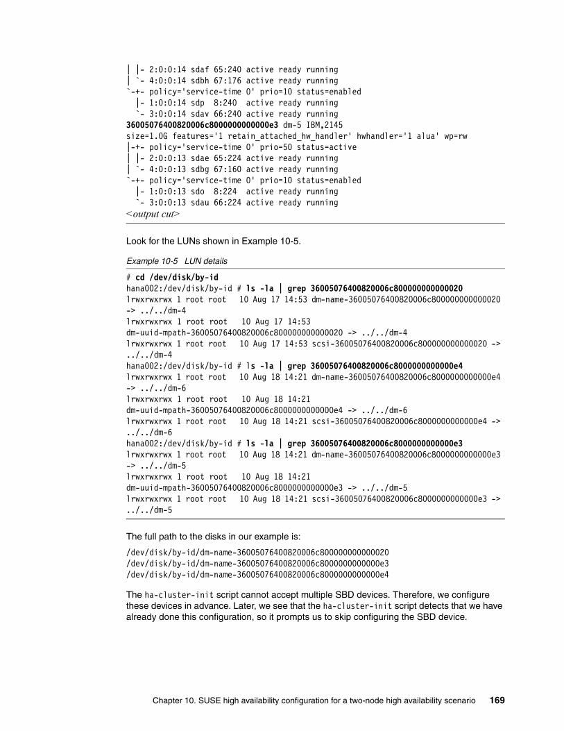
| |- 2:0:0:14 sdaf 65:240 active ready running| `- 4:0:0:14 sdbh 67:176 active ready running`-+- policy='service-time 0' prio=10 status=enabled |- 1:0:0:14 sdp 8:240 active ready running `- 3:0:0:14 sdav 66:240 active ready running36005076400820006c8000000000000e3 dm-5 IBM,2145size=1.0G features='1 retain_attached_hw_handler' hwhandler='1 alua' wp=rw|-+- policy='service-time 0' prio=50 status=active| |- 2:0:0:13 sdae 65:224 active ready running| `- 4:0:0:13 sdbg 67:160 active ready running`-+- policy='service-time 0' prio=10 status=enabled |- 1:0:0:13 sdo 8:224 active ready running `- 3:0:0:13 sdau 66:224 active ready running<output cut>
Look for the LUNs shown in Example 10-5.
Example 10-5 LUN details
# cd /dev/disk/by-idhana002:/dev/disk/by-id # ls -la | grep 36005076400820006c800000000000020lrwxrwxrwx 1 root root 10 Aug 17 14:53 dm-name-36005076400820006c800000000000020 -> ../../dm-4lrwxrwxrwx 1 root root 10 Aug 17 14:53 dm-uuid-mpath-36005076400820006c800000000000020 -> ../../dm-4lrwxrwxrwx 1 root root 10 Aug 17 14:53 scsi-36005076400820006c800000000000020 -> ../../dm-4hana002:/dev/disk/by-id # ls -la | grep 36005076400820006c8000000000000e4lrwxrwxrwx 1 root root 10 Aug 18 14:21 dm-name-36005076400820006c8000000000000e4 -> ../../dm-6lrwxrwxrwx 1 root root 10 Aug 18 14:21 dm-uuid-mpath-36005076400820006c8000000000000e4 -> ../../dm-6lrwxrwxrwx 1 root root 10 Aug 18 14:21 scsi-36005076400820006c8000000000000e4 -> ../../dm-6hana002:/dev/disk/by-id # ls -la | grep 36005076400820006c8000000000000e3lrwxrwxrwx 1 root root 10 Aug 18 14:21 dm-name-36005076400820006c8000000000000e3 -> ../../dm-5lrwxrwxrwx 1 root root 10 Aug 18 14:21 dm-uuid-mpath-36005076400820006c8000000000000e3 -> ../../dm-5lrwxrwxrwx 1 root root 10 Aug 18 14:21 scsi-36005076400820006c8000000000000e3 -> ../../dm-5
The full path to the disks in our example is:
/dev/disk/by-id/dm-name-36005076400820006c800000000000020/dev/disk/by-id/dm-name-36005076400820006c8000000000000e3/dev/disk/by-id/dm-name-36005076400820006c8000000000000e4
The ha-cluster-init script cannot accept multiple SBD devices. Therefore, we configure these devices in advance. Later, we see that the ha-cluster-init script detects that we have already done this configuration, so it prompts us to skip configuring the SBD device.
Chapter 10. SUSE high availability configuration for a two-node high availability scenario 169

If not already done, you must create the physical volume devices for the three SBD LUNs. This process must be completed on both hosts, as shown in Example 10-6.
Example 10-6 The pvcreate command for SBD LUNs
# pvcreate /dev/mapper/36005076400820006c800000000000020Physical volume "/dev/mapper/36005076400820006c800000000000020" successfully created
# pvcreate /dev/mapper/36005076400820006c8000000000000e3 Physical volume "/dev/mapper/36005076400820006c8000000000000e3" successfully created
# pvcreate /dev/mapper/36005076400820006c8000000000000e4Physical volume "/dev/mapper/36005076400820006c8000000000000e4" successfully created
Now, configure these three LUNs as SBD devices. Change the msgwait (-4) and watchdog (-1) timeouts to 180 and 90 respectively, as shown in Example 10-7. Again, this is performed from hana002.
Example 10-7 Configuring the LUNs
# sbd -d /dev/disk/by-id/dm-name-36005076400820006c800000000000020 -d /dev/disk/by-id/dm-name-36005076400820006c8000000000000e3 -d /dev/disk/by-id/dm-name-36005076400820006c8000000000000e4 -4 180 -1 90 create
From both nodes, check that the information can be read from the headers. The information matches when run from both nodes, as shown in Example 10-8.
Example 10-8 The sbd -d <DISK> dump command
hana002:~ # sbd -d /dev/disk/by-id/dm-name-36005076400820006c800000000000020 -d /dev/disk/by-id/dm-name-36005076400820006c8000000000000e3 -d /dev/disk/by-id/dm-name-36005076400820006c8000000000000e4 dump==Dumping header on disk /dev/disk/by-id/dm-name-36005076400820006c800000000000020Header version : 2.1UUID : a1d5dc47-af2d-48e3-92f8-cbe82523b7c2Number of slots : 255Sector size : 512Timeout (watchdog) : 90Timeout (allocate) : 2Timeout (loop) : 1Timeout (msgwait) : 180==Header on disk /dev/disk/by-id/dm-name-36005076400820006c800000000000020 is dumped==Dumping header on disk /dev/disk/by-id/dm-name-36005076400820006c8000000000000e3Header version : 2.1UUID : 57fb32a8-b544-415a-a77d-1a32f3b0a663Number of slots : 255Sector size : 512Timeout (watchdog) : 90Timeout (allocate) : 2Timeout (loop) : 1Timeout (msgwait) : 180==Header on disk /dev/disk/by-id/dm-name-36005076400820006c8000000000000e3 is dumped
170 Implementing High Availability and Disaster Recovery Solutions with SAP HANA on IBM Power Systems

==Dumping header on disk /dev/disk/by-id/dm-name-36005076400820006c8000000000000e4Header version : 2.1UUID : 19436144-b344-43fb-a8df-41f0a1e4a95fNumber of slots : 255Sector size : 512Timeout (watchdog) : 90Timeout (allocate) : 2Timeout (loop) : 1Timeout (msgwait) : 180==Header on disk /dev/disk/by-id/dm-name-36005076400820006c8000000000000e4 is dumped
These three LUNs can be added to the /etc/sysconfig/sbd file on hana002. The second node, hana003, gets this configuration file from the corosync process later.
Find the SBD_DEVICE section and add your LUNs so that it matches Example 10-9. Each entry is separated with a semicolon.
Example 10-9 SBD_DEVICE in /etc/sysconfig/sbd
SBD_DEVICE="/dev/disk/by-id/dm-name-36005076400820006c800000000000020; /dev/disk/by-id/dm-name-36005076400820006c8000000000000e3; /dev/disk/by-id/dm-name-36005076400820006c8000000000000e4"
This concludes the configuration of the SBD devices. For more information about storage-based fencing, see SUSE Doc: Administration Guide - Storage-based Fencing.
10.2.2 Hardware Management Console
The HMC can be configured as a STONITH device. In our example, we use a storage-based device.
To configure the HMC as a STONITH device, you must complete the following steps on both nodes:
1. Exchange SSH keys with your HMC and test access, as shown in Example 10-10.
Example 10-10 Exchanging SSK Keys with the HMC
# KEY=`cat ~/.ssh/id_rsa.pub` && ssh [email protected] mkauthkeys -a \"$KEY\"The authenticity of host 'a.b.c.d (a.b.c.d)' can't be established.ECDSA key fingerprint is dc:ec:ed:fa:27:b6:e7:bd:b7:03:aa:86:61:ed:7d:df [MD5].Are you sure you want to continue connecting (yes/no)? yesWarning: Permanently added 'a.b.c.d' (ECDSA) to the list of known [email protected]'s password:
# ssh [email protected] login: Mon Jun 5 21:45:19 2017 from sig-9-83-192-100.evts.uk.ibm.comhscroot@hmc10:~> exit
Where a.b.c.d is the IP address of your HMC.
Chapter 10. SUSE high availability configuration for a two-node high availability scenario 171

2. Create a text file with the configuration for the HMC as a STONITH and call it crm-stonith.txt, as shown in Example 10-11.
Example 10-11 The crm-stonith.txt file
# File: crm-stonith.txt
primitive rsc_hmc10 stonith:ibmhmc \params managedsyspat="hana002 hana003" ipaddr="a.b.c.d" \op monitor timeout=20 interval=3600 \op start timout=20 interval=0 \op stop timeout=15 interval=0
clone clone_hmc10 rsc_hmc10 \meta target-role="Stopped"
The file, which we place in /tmp, can be used to load the cluster configuration, as shown in Example 10-12.
Example 10-12 Loading the configuration file by using the crm command-line interface tool
# crm configure load update /tmp/crm-stonith.txt
10.3 Stopping SAP HANA
You must stop the SAP HANA instances on both nodes. Stop the instance on the primary source node first, and then on the secondary target node. Example 10-13 shows stopping the primary HANA instance on hana002.
Example 10-13 Stopping the HANA instance on hana002
rb1adm@hana002:/usr/sap/RB1/HDB00> HDB stophdbdaemon will wait maximal 300 seconds for NewDB services finishing.Stopping instance using: /usr/sap/RB1/SYS/exe/hdb/sapcontrol -prot NI_HTTP -nr 00 -function Stop 400
12.07.2017 14:48:23StopOKWaiting for stopped instance using: /usr/sap/RB1/SYS/exe/hdb/sapcontrol -prot NI_HTTP -nr 00 -function WaitforStopped 600 2
12.07.2017 14:49:03WaitforStoppedOKhdbdaemon is stopped.
Example 10-14 shows stopping the secondary HANA instance on hana003.
Example 10-14 Stopping the HANA instance on hana003
rb1adm@hana003:/usr/sap/RB1/HDB00> HDB stophdbdaemon will wait maximal 300 seconds for NewDB services finishing.Stopping instance using: /usr/sap/RB1/SYS/exe/hdb/sapcontrol -prot NI_HTTP -nr 00 -function Stop 400
172 Implementing High Availability and Disaster Recovery Solutions with SAP HANA on IBM Power Systems

12.07.2017 14:49:23StopOKWaiting for stopped instance using: /usr/sap/RB1/SYS/exe/hdb/sapcontrol -prot NI_HTTP -nr 00 -function WaitforStopped 600 2
12.07.2017 14:49:29WaitforStoppedOKhdbdaemon is stopped.
Table 10-2 shows the current system status.
Table 10-2 System status
10.4 Watchdog
The ha-cluster-init process calls for a watchdog service. Because there is no hardware watchdog service that is available for IBM Power Systems, we use softdog.
Example 10-15 shows softdog being enabled and the systemd-modules-load service being restarted. Check that the module is correctly loaded by running lsmod. This process must be performed on both nodes.
Example 10-15 The softdog enabling process
# echo softdog > /etc/modules-load.d/watchdog.conf# systemctl restart systemd-modules-load# lsmod | grep dogsoftdog 4961 0
10.5 The ha-cluster-init process
Start the cluster configuration from the source node hana002. By default, the ha-cluster-init process configures corosync to use multicast. However, by using the -u switch, you can configure the cluster to use unicast, as shown in Example 10-16.
Example 10-16 Initial cluster configuration with unicast
hana002:~ # ha-cluster-init -u Enabling sshd.service /root/.ssh/id_rsa already exists - overwrite? [y/N] N Configuring csync2 Generating csync2 shared key (this may take a while)...done Enabling csync2.socket
Host HANA status Replication role Replication status
hana002 Stopped Source Stopped
hana003 Stopped Target Stopped
Chapter 10. SUSE high availability configuration for a two-node high availability scenario 173

csync2 checking files/usr/sbin/ha-cluster-init: line 403: dmidecode: command not found
Configure Corosync (unicast): This will configure the cluster messaging layer. You will need to specify a network address over which to communicate (default is eth0's network, but you can use the network address of any active interface).
Network address to bind to (e.g.: 192.168.1.0) [9.196.156.0] Port [5405]
Configure SBD: If you have shared storage, for example a SAN or iSCSI target, you can use it avoid split-brain scenarios by configuring SBD. This requires a 1 MB partition, accessible to all nodes in the cluster. The device path must be persistent and consistent across all nodes in the cluster, so /dev/disk/by-id/* devices are a good choice. Note that all data on the partition you specify here will be destroyed.
SBD is already configured - overwrite? [y/N] N Enabling hawk.service HA Web Konsole is now running, to see cluster status go to: https://9.196.156.71:7630/ Log in with username 'hacluster', password 'linux'WARNING: You should change the hacluster password to something more secure! Enabling pacemaker.service Waiting for cluster........done Loading initial configuration
Configure Administration IP Address: Optionally configure an administration virtual IP address. The purpose of this IP address is to provide a single IP that can be used to interact with the cluster, rather than using the IP address of any specific cluster node.
Do you wish to configure an administration IP? [y/N] n Done (log saved to /var/log/ha-cluster-bootstrap.log)
Follow these preferred practices:
� Do not create SSH keys.
� Accept the network address to bind to (this is one of the networks that you want to use for corosync). In our environment, it is 9.196.156.0.
� Accept the defaults for the port.
� Do not overwrite the SBD configuration.
� Do not configure an administration IP address (this is up to preferences). If you want to configure it, you need another IP address in the same range and it must be in the /etc/hosts file on both nodes in your cluster.
174 Implementing High Availability and Disaster Recovery Solutions with SAP HANA on IBM Power Systems
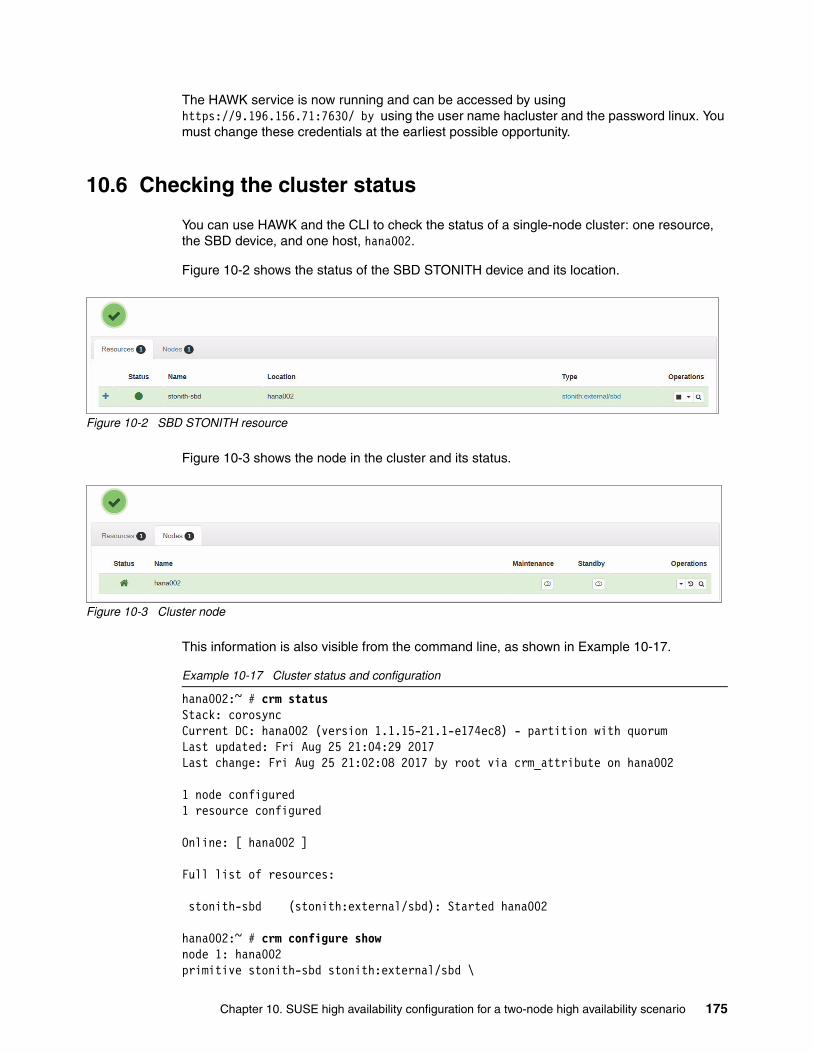
The HAWK service is now running and can be accessed by using https://9.196.156.71:7630/ by using the user name hacluster and the password linux. You must change these credentials at the earliest possible opportunity.
10.6 Checking the cluster status
You can use HAWK and the CLI to check the status of a single-node cluster: one resource, the SBD device, and one host, hana002.
Figure 10-2 shows the status of the SBD STONITH device and its location.
Figure 10-2 SBD STONITH resource
Figure 10-3 shows the node in the cluster and its status.
Figure 10-3 Cluster node
This information is also visible from the command line, as shown in Example 10-17.
Example 10-17 Cluster status and configuration
hana002:~ # crm statusStack: corosyncCurrent DC: hana002 (version 1.1.15-21.1-e174ec8) - partition with quorumLast updated: Fri Aug 25 21:04:29 2017Last change: Fri Aug 25 21:02:08 2017 by root via crm_attribute on hana002
1 node configured1 resource configured
Online: [ hana002 ]
Full list of resources:
stonith-sbd (stonith:external/sbd): Started hana002
hana002:~ # crm configure shownode 1: hana002primitive stonith-sbd stonith:external/sbd \
Chapter 10. SUSE high availability configuration for a two-node high availability scenario 175

params pcmk_delay_max=30sproperty cib-bootstrap-options: \ have-watchdog=true \ dc-version=1.1.15-21.1-e174ec8 \ cluster-infrastructure=corosync \ cluster-name=hacluster \ stonith-enabled=true \ placement-strategy=balanced \ stonith-timeout=259rsc_defaults rsc-options: \ resource-stickiness=1 \ migration-threshold=3op_defaults op-options: \ timeout=600 \ record-pending=true
10.7 The ha-cluster-join command
The initial cluster configuration is complete. Integrate the second node, hana003, into the cluster, as shown in Example 10-18.
Example 10-18 The ha-cluster-join command
hana003:~ # ha-cluster-join
Join This Node to Cluster: You will be asked for the IP address of an existing node, from which configuration will be copied. If you have not already configured passwordless ssh between nodes, you will be prompted for the root password of the existing node.
IP address or hostname of existing node (e.g.: 192.168.1.1) [] 9.196.156.71 Enabling sshd.service Retrieving SSH keys from 9.196.156.71 /root/.ssh/id_rsa already exists - overwrite? [y/N] N No new SSH keys installed Configuring csync2 Enabling csync2.socket Merging known_hosts Probing for new partitions......done Enabling hawk.service HA Web Konsole is now running, to see cluster status go to: https://9.196.156.72:7630/ Log in with username 'hacluster', password 'linux'WARNING: You should change the hacluster password to something more secure! Enabling pacemaker.service Waiting for cluster........doneOK: [hana003]NoneOK: [hana002]None Done (log saved to /var/log/ha-cluster-bootstrap.log)
176 Implementing High Availability and Disaster Recovery Solutions with SAP HANA on IBM Power Systems

You must change the HAWK logon credentials at the earliest possible opportunity.
You can encounter a problem with the synchronization of some files by using csync2. If you encounter this issue, you must find which files did not synchronize to rectify this issue by completing the following actions.
From hana002, check which files are out of sync or missing compared to hana003, as shown in Example 10-19.
Example 10-19 The csync2 -xv command
hana002:~ # csync2 -xvConnecting to host hana003 (SSL) ...Connect to 9.196.156.72:30865 (hana003).Updating /etc/sysconfig/pacemaker on hana003 ...File stays in dirty state. Try again later...Updating /etc/sysconfig/sbd on hana003 ...File stays in dirty state. Try again later...Connection closed.Finished with 2 errors.
The -f switch with the csync2 command runs checks for all given files and updates the remote hosts. The subsequent csync2 -xv command that is shown in Example 10-20 passes because the state of /etc/sysconfig/pacemaker, /etc/sysconfig/sbd, and /etc/modules-load.d/watchdog.conf files in hana002 and hana003 are now consistent. We include /etc/modules-load.d/watchdog.conf, and although not listed as failed, it is critical that these files are the same on each server.
Example 10-20 The csync2 -f pacemaker, sbd, and watchdog commands
hana002:~ # csync2 -f /etc/sysconfig/pacemakerhana002:~ # csync2 -f /etc/sysconfig/sbdhana002:~ # csync2 -f /etc/modules-load.d/watchdog.confhana002:~ # csync2 -xvConnecting to host hana003 (SSL) ...Connect to 9.196.156.72:30865 (hana003).Updating /etc/sysconfig/pacemaker on hana003 ...Updating /etc/sysconfig/sbd on hana003 ...Updating /etc/modules-load.d/watchdog.conf on hana003 ...Connection closed.Finished with 0 errors.
Chapter 10. SUSE high availability configuration for a two-node high availability scenario 177

Figure 10-4 List of Csync2 files
Now, looking at HAWK from hana002, you see that the second node joined the cluster, as shown in Figure 10-5.
Figure 10-5 HAWK showing two nodes
Note: Csync2 can be temperamental, so to ensure that all files are synchronized, perform a manual check of the files. You can find a list of files to be synchronized in the YaST2 Cluster interface under Configure Csync2, as shown in Figure 10-4.
178 Implementing High Availability and Disaster Recovery Solutions with SAP HANA on IBM Power Systems

10.8 Updating the cluster configuration
It is advantageous to stop and start cluster services before integrating SAP HANA into the cluster. You can also take this opportunity to change some cluster settings.
Table 10-3 shows the current system status.
Table 10-3 System status
Complete the following steps:
1. Stop pacemaker.service on hana002 and hana003. When the services stop (you can check by running systemctl status pacemaker.service), then they can be restarted.
You must wait for the services to stop on both nodes before restarting the service on either node, as shown in Example 10-21. Note the host order in which we are stopping these services.
Example 10-21 Stopping and starting pacemaker on both nodes
hana003:~ # systemctl stop pacemaker.service
hana003:~ # systemctl status pacemaker.service
hana002:~ # systemctl stop pacemaker.service
hana002:~ # systemctl status pacemaker.service
2. On hana002, change the entry in /etc/corosync/corosync.conf. By default, to_logfile is set to no, so change it to yes, as shown in Example 10-22.
Example 10-22 Turning on corosync log file
logging { fileline: off to_stderr: no to_logfile: yes logfile: /var/log/cluster/corosync.log
3. Push this configuration change to the second node by using csync2, as shown in Example 10-23.
Example 10-23 Pushing the configuration change
hana002:~ # csync2 -xvMarking file as dirty: /etc/corosync/corosync.confConnecting to host hana003 (SSL) ...Connect to 9.196.156.72:30865 (hana003).Updating /etc/corosync/corosync.conf on hana003 ...
Host HANA status Replication role Replication status
hana002 Stopped Source Stopped
hana003 Stopped Target Stopped
Note: The automatic start of the pacemaker service is still enabled on hana003. This must be manually changed by using the YaST Cluster application.
Chapter 10. SUSE high availability configuration for a two-node high availability scenario 179
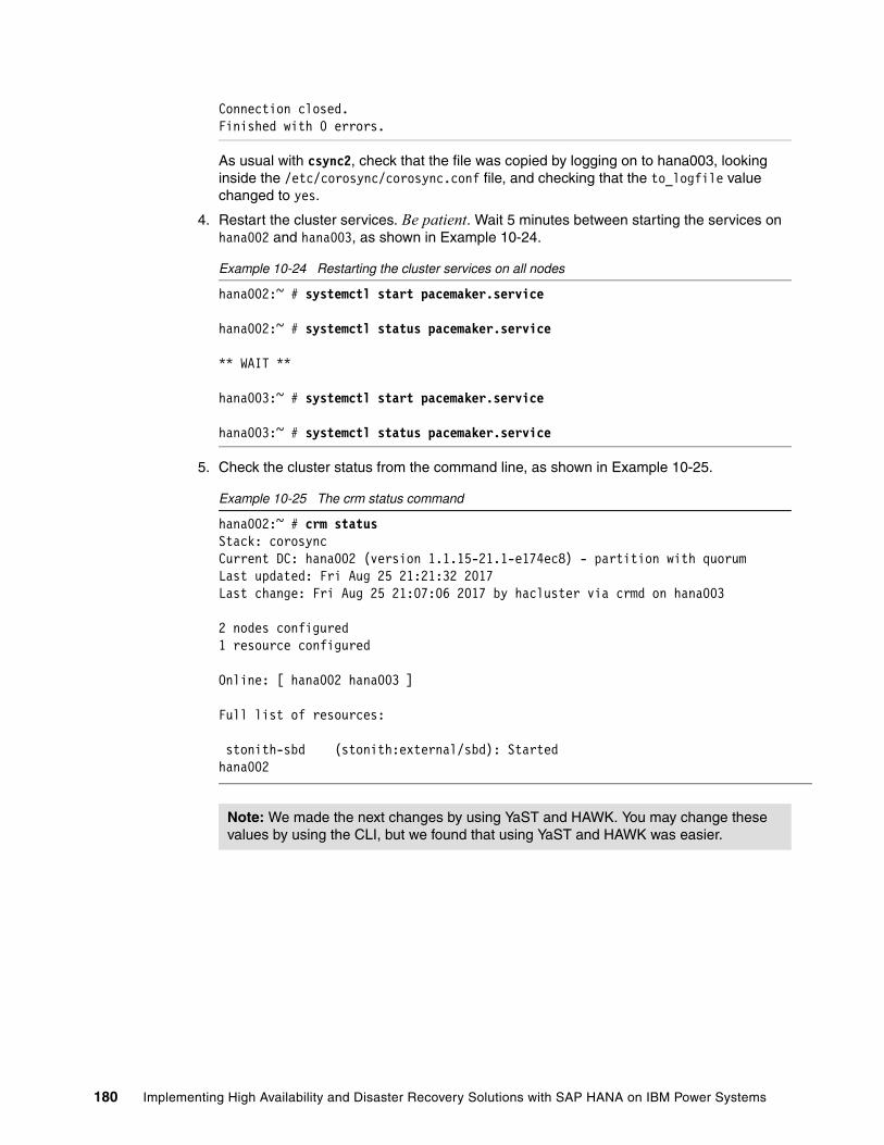
Connection closed.Finished with 0 errors.
As usual with csync2, check that the file was copied by logging on to hana003, looking inside the /etc/corosync/corosync.conf file, and checking that the to_logfile value changed to yes.
4. Restart the cluster services. Be patient. Wait 5 minutes between starting the services on hana002 and hana003, as shown in Example 10-24.
Example 10-24 Restarting the cluster services on all nodes
hana002:~ # systemctl start pacemaker.service
hana002:~ # systemctl status pacemaker.service
** WAIT **
hana003:~ # systemctl start pacemaker.service
hana003:~ # systemctl status pacemaker.service
5. Check the cluster status from the command line, as shown in Example 10-25.
Example 10-25 The crm status command
hana002:~ # crm statusStack: corosyncCurrent DC: hana002 (version 1.1.15-21.1-e174ec8) - partition with quorumLast updated: Fri Aug 25 21:21:32 2017Last change: Fri Aug 25 21:07:06 2017 by hacluster via crmd on hana003
2 nodes configured1 resource configured
Online: [ hana002 hana003 ]
Full list of resources:
stonith-sbd (stonith:external/sbd): Started hana002
Note: We made the next changes by using YaST and HAWK. You may change these values by using the CLI, but we found that using YaST and HAWK was easier.
180 Implementing High Availability and Disaster Recovery Solutions with SAP HANA on IBM Power Systems

6. Click Applications → System Tools → YaST → Cluster. The window that is shown in Figure 10-6 opens.
Figure 10-6 YaST cluster
Complete the following steps:
a. Edit and check the member IP addresses of each node in your cluster so that they are the actual IP addresses and not the host names.
b. Change the name of your cluster to one that is relevant to your environment.
You cannot close this window until you change the member IP addresses to the IP addresses and not the host names. If you try to move forward, you see the error that is shown in Figure 10-7.
Figure 10-7 Warning YaST2 window
Chapter 10. SUSE high availability configuration for a two-node high availability scenario 181

Figure 10-8 shows the updated settings.
Figure 10-8 Member IP addresses added and cluster name changed
182 Implementing High Availability and Disaster Recovery Solutions with SAP HANA on IBM Power Systems

7. Change the cluster service so that it does not start on boot, as shown in Figure 10-9.
Figure 10-9 Change booting to Off -- Start pacemaker manually
8. Click Finish to save your changes.
You must change the cluster service to not start at boot on all nodes. This setting is not synchronized. You must manually log on to the secondary node and change it to Off -- Start pacemaker manually.
In this scenario, we configured only a single corosync ring. It is strongly advised to configure a second corosync ring. Typically, there are at least two networks available: a data network and a replication network, for example.
Chapter 10. SUSE high availability configuration for a two-node high availability scenario 183

To configure the second ring, complete the following steps:
1. Open the YaST2 cluster on the first node and select Redundant Channel, as shown in Figure 10-10.
Figure 10-10 Configuring the redundant channel
2. Select the network that you want to use for your redundant channel, click Add, and enter the address of each node in the cluster on that network.
3. Synchronize these changes to the second node by using csync2, as shown in Example 10-26.
Example 10-26 Synchronizing the cluster nodes
hana002:~ # csync2 -xvMarking file as dirty: /etc/sysconfig/pacemakerMarking file as dirty: /etc/csync2/csync2.cfgMarking file as dirty: /etc/corosync/corosync.confConnecting to host hana003 (SSL) ...Connect to 9.196.156.72:30865 (hana003).Updating /etc/corosync/corosync.conf on hana003 ...Updating /etc/csync2/csync2.cfg on hana003 ...File is already up to date on peer.Updating /etc/sysconfig/pacemaker on hana003 ...
184 Implementing High Availability and Disaster Recovery Solutions with SAP HANA on IBM Power Systems

Connection closed.Finished with 0 errors.
4. Log on to HAWK from the primary node to change the no-quorum policy to ignore. To do this task, click Cluster Configuration, as shown in Figure 10-11.
Figure 10-11 Cluster configuration
Using the drop-down menu, highlighted in Figure 10-12, it is possible to add new policies to the cluster.
Figure 10-12 Cluster configuration drop-down menu
Chapter 10. SUSE high availability configuration for a two-node high availability scenario 185

In this instance, we want to add the no-quorum-policy. Select it from the drop-down list and click +, as shown in Figure 10-13.
Figure 10-13 Adding no-quorum-policy
Figure 10-14 shows the new configuration value set to ignore by using the drop-down menu.
Figure 10-14 Setting the policy value to ignore
186 Implementing High Availability and Disaster Recovery Solutions with SAP HANA on IBM Power Systems

5. Click Apply to save the changes, as shown in Figure 10-15.
Figure 10-15 Applying changes
This action automatically pushes the configuration to the secondary node. You can check that the action is completed by looking at the cluster config on both nodes, as shown in Example 10-27.
Example 10-27 Checking the cluster configuration after the configuration changes
hana002:~ # crm configure shownode 1: hana002node 2: hana003primitive stonith-sbd stonith:external/sbd \ params pcmk_delay_max=30sproperty cib-bootstrap-options: \ have-watchdog=true \ dc-version=1.1.15-21.1-e174ec8 \ cluster-infrastructure=corosync \ cluster-name=hacluster \ stonith-enabled=true \ placement-strategy=balanced \ stonith-timeout=259 \ no-quorum-policy=ignorersc_defaults rsc-options: \
Chapter 10. SUSE high availability configuration for a two-node high availability scenario 187

resource-stickiness=1 \ migration-threshold=3op_defaults op-options: \ timeout=600 \ record-pending=true
hana003:~ # crm configure shownode 1: hana002node 2: hana003primitive stonith-sbd stonith:external/sbd \ params pcmk_delay_max=30sproperty cib-bootstrap-options: \ have-watchdog=true \ dc-version=1.1.15-21.1-e174ec8 \ cluster-infrastructure=corosync \ cluster-name=hacluster \ stonith-enabled=true \ placement-strategy=balanced \ stonith-timeout=259 \ no-quorum-policy=ignorersc_defaults rsc-options: \ resource-stickiness=1 \ migration-threshold=3op_defaults op-options: \ timeout=600 \ record-pending=true
6. Afterward, restart the cluster services before integrating SAP HANA, as shown in Example 10-28.
Example 10-28 Restarting the cluster services
hana003:~ # systemctl stop pacemaker.service
hana003:~ # systemctl status pacemaker.service
** WAIT **
hana002:~ # systemctl stop pacemaker.service
hana002:~ # systemctl status pacemaker.service
** WAIT **
hana002:~ # systemctl start pacemaker.service
hana002:~ # systemctl status pacemaker.service
** WAIT **
hana003:~ # systemctl start pacemaker.service
hana003:~ # systemctl status pacemaker.service
188 Implementing High Availability and Disaster Recovery Solutions with SAP HANA on IBM Power Systems
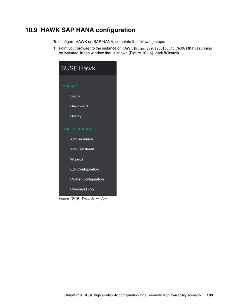
10.9 HAWK SAP HANA configuration
To configure HAWK on SAP HANA, complete the following steps:
1. Point your browser to the instance of HAWK (https://9.196.156.71:7630/) that is running on hana002. In the window that is shown (Figure 10-16), click Wizards.
Figure 10-16 Wizards window
Chapter 10. SUSE high availability configuration for a two-node high availability scenario 189

The SAP HANA SR Scale-Up Performance-Optimized agent is in the SAP section, as shown in Figure 10-17.
Figure 10-17 Performance-Optimized Agent
190 Implementing High Availability and Disaster Recovery Solutions with SAP HANA on IBM Power Systems

2. Click the green plus icon to proceed to the next window (Figure 10-18), where you are prompted for the SID, instance number, and floating/virtual/service IP address of your SAP HANA instance. Additionally, you can specify the prefer_site_takeover and automated_register values. The values in these fields are suggestions only. Each value in the Advanced section has a brief description that is associated with it.
Figure 10-18 SAP HANA System Replication
3. Click Verify when you have input details into each of the fields. After the configuration is verified, click Apply.
As this process proceeds, SAP HANA is started on both hana002 and hana003, and the system replication process also restarts.
Chapter 10. SUSE high availability configuration for a two-node high availability scenario 191

This process can take some time. Be patient. After the process completes, the webpage refreshes and you see a message, as shown in Figure 10-19.
Figure 10-19 Changes that are applied successfully
Table 10-4 shows the current system status.
Table 10-4 System status
Figure 10-20 shows the status of the cluster as seen from HAWK on hana002.
Figure 10-20 HAWK status
You can check the cluster status from the command line, as shown in Example 10-29.
Example 10-29 The crm command status with HANA resources running
hana002:/usr/share # crm statusStack: corosyncCurrent DC: hana002 (version 1.1.15-21.1-e174ec8) - partition with quorumLast updated: Fri Aug 25 22:25:28 2017Last change: Fri Aug 25 22:24:44 2017 by root via crm_attribute on hana002
2 nodes configured
Host HANA status Replication role Replication status
hana002 Running Source Running
hana003 Running Target Running
192 Implementing High Availability and Disaster Recovery Solutions with SAP HANA on IBM Power Systems

6 resources configured
Online: [ hana002 hana003 ]
Full list of resources:
stonith-sbd (stonith:external/sbd): Started hana002 rsc_ip_RB1_HDB00 (ocf::heartbeat:IPaddr2): Started hana002 Master/Slave Set: msl_SAPHana_RB1_HDB00 [rsc_SAPHana_RB1_HDB00] Masters: [ hana002 ] Slaves: [ hana003 ] Clone Set: cln_SAPHanaTopology_RB1_HDB00 [rsc_SAPHanaTopology_RB1_HDB00] Started: [ hana002 hana003 ]
Check that the service IP address is added to the correct interface on hana002, as shown in Example 10-30.
Example 10-30 Showing the service address
hana002:~ # ip addr show1: lo: <LOOPBACK,UP,LOWER_UP> mtu 65536 qdisc noqueue state UNKNOWN group default qlen 1 link/loopback 00:00:00:00:00:00 brd 00:00:00:00:00:00 inet 127.0.0.1/8 scope host lo valid_lft forever preferred_lft forever inet6 ::1/128 scope host valid_lft forever preferred_lft forever2: eth0: <BROADCAST,MULTICAST,UP,LOWER_UP> mtu 1500 qdisc pfifo_fast state UNKNOWN group default qlen 1000 link/ether ca:66:25:17:e8:02 brd ff:ff:ff:ff:ff:ff inet 9.196.156.71/24 brd 9.196.156.255 scope global eth0 valid_lft forever preferred_lft forever inet 9.196.156.70/24 brd 9.196.156.255 scope global secondary eth0 valid_lft forever preferred_lft forever inet6 fe80::c866:25ff:fe17:e802/64 scope link valid_lft forever preferred_lft forever
Check the corosync status in both nodes. The corosync status for hana002 is shown in Example 10-31.
Example 10-31 The hana002 corosync status
hana002:/var/log # /usr/sbin/corosync-cfgtool -sPrinting ring status.Local node ID 1RING ID 0 id = 9.196.156.71 status = ring 0 active with no faults
The corosync status for hana003 is shown in Example 10-32.
Example 10-32 The hana003 corosync status
hana003:/var/log # /usr/sbin/corosync-cfgtool -sPrinting ring status.Local node ID 2
Chapter 10. SUSE high availability configuration for a two-node high availability scenario 193

RING ID 0 id = 9.196.156.72 status = ring 0 active with no faults
10.10 Maintenance
This section describes two common tasks and scenarios. This is not an exhaustive list of scenarios that you can come across in the lifetime of supporting this cluster. You can check your experiences with other cluster software and use them as a basis to draw up a detailed test plan.
10.10.1 Simulated failure and recovery
This scenario simulates the complete failure of hana002. This scenario shows the failover of the resources to hana003, the recovery of hana002, the reverse of the replication so that hana002 is now the target, and then the process for reverting the cluster back to its original state. The state of both nodes at the start of these tests is shown in Table 10-5.
Table 10-5 System status
Example 10-33 shows the initial status of hana002 from the CLI.
Example 10-33 Initial status of hana002
hana002:~ # crm statusStack: corosyncCurrent DC: hana002 (version 1.1.15-21.1-e174ec8) - partition with quorumLast updated: Thu Jul 13 20:22:11 2017Last change: Thu Jul 13 20:21:55 2017 by root via crm_attribute on hana002
2 nodes configured6 resources configured
Online: [ hana002 hana003 ]
Full list of resources:
stonith-sbd (stonith:external/sbd): Started hana002 rsc_ip_RB1_HDB00 (ocf::heartbeat:IPaddr2): Started hana002 Master/Slave Set: msl_SAPHana_RB1_HDB00 [rsc_SAPHana_RB1_HDB00] Masters: [ hana002 ] Slaves: [ hana003 ]
Hosts Operating system status
HANA status SUSE Linux Enterprise Server high availability status
Replication status
hana002 Running Running Active / Primary Active / Source
hana003 Running Running Active / Secondary
Active / Target
194 Implementing High Availability and Disaster Recovery Solutions with SAP HANA on IBM Power Systems

Clone Set: cln_SAPHanaTopology_RB1_HDB00 [rsc_SAPHanaTopology_RB1_HDB00] Started: [ hana002 hana003 ]
Example 10-34 shows the initial status of hana003 from the CLI.
Example 10-34 Initial status of hana003
hana003:~ # crm statusStack: corosyncCurrent DC: hana002 (version 1.1.15-21.1-e174ec8) - partition with quorumLast updated: Thu Jul 13 20:23:07 2017Last change: Thu Jul 13 20:23:02 2017 by root via crm_attribute on hana002
2 nodes configured6 resources configured
Online: [ hana002 hana003 ]
Full list of resources:
stonith-sbd (stonith:external/sbd): Started hana002 rsc_ip_RB1_HDB00 (ocf::heartbeat:IPaddr2): Started hana002 Master/Slave Set: msl_SAPHana_RB1_HDB00 [rsc_SAPHana_RB1_HDB00] Masters: [ hana002 ] Slaves: [ hana003 ] Clone Set: cln_SAPHanaTopology_RB1_HDB00 [rsc_SAPHanaTopology_RB1_HDB00] Started: [ hana002 hana003 ]
Example 10-35 shows the hana002 service address.
Example 10-35 The hana002 node showing the service address
hana002:~ # ip addr show1: lo: <LOOPBACK,UP,LOWER_UP> mtu 65536 qdisc noqueue state UNKNOWN group default qlen 1 link/loopback 00:00:00:00:00:00 brd 00:00:00:00:00:00 inet 127.0.0.1/8 scope host lo valid_lft forever preferred_lft forever inet6 ::1/128 scope host valid_lft forever preferred_lft forever2: eth0: <BROADCAST,MULTICAST,UP,LOWER_UP> mtu 1500 qdisc pfifo_fast state UNKNOWN group default qlen 1000 link/ether ca:66:25:17:e8:02 brd ff:ff:ff:ff:ff:ff inet 9.196.156.71/24 brd 9.196.156.255 scope global eth0 valid_lft forever preferred_lft forever inet 9.196.156.70/24 brd 9.196.156.255 scope global secondary eth0 valid_lft forever preferred_lft forever inet6 fe80::c866:25ff:fe17:e802/64 scope link valid_lft forever preferred_lft forever
Failing the primary nodeYou can monitor the progress of the failover by using HAWK on hana003 or by running the crm_mon -r command on hana003.
Chapter 10. SUSE high availability configuration for a two-node high availability scenario 195

Fail hana002, as shown in Example 10-36.
Example 10-36 Halting hana002
hana002:~ # halt
Example 10-37 shows the failover progress of hana002 from hana003.
Example 10-37 Failover in progress as viewed from hana003
hana003:~ # crm_mon -rStack: corosyncCurrent DC: hana002 (version 1.1.15-21.1-e174ec8) - partition with quorumLast updated: Sun Aug 27 00:57:37 2017Last change: Sun Aug 27 00:57:34 2017 by root via crm_attribute on hana003
2 nodes configured6 resources configured
Online: [ hana002 hana003 ]
Full list of resources:
stonith-sbd (stonith:external/sbd): Started hana003rsc_ip_RB1_HDB00 (ocf::heartbeat:IPaddr2): Started hana003 Master/Slave Set: msl_SAPHana_RB1_HDB00 [rsc_SAPHana_RB1_HDB00] rsc_SAPHana_RB1_HDB00 (ocf::suse:SAPHana): Promoting hana003 Stopped: [ hana002 ] Clone Set: cln_SAPHanaTopology_RB1_HDB00 [rsc_SAPHanaTopology_RB1_HDB00] Started: [ hana003 ] Stopped: [ hana002 ]
Figure 10-21 shows the failover progress of hana002 as viewed from HAWK on hana003.
Figure 10-21 Failover in progress as viewed from HAWK on hana003
196 Implementing High Availability and Disaster Recovery Solutions with SAP HANA on IBM Power Systems

Example 10-38 shows the service address failed over to hana003.
Example 10-38 Service address failed over to hana003
hana003:~ # ip addr show1: lo: <LOOPBACK,UP,LOWER_UP> mtu 65536 qdisc noqueue state UNKNOWN group default qlen 1 link/loopback 00:00:00:00:00:00 brd 00:00:00:00:00:00 inet 127.0.0.1/8 scope host lo valid_lft forever preferred_lft forever inet6 ::1/128 scope host valid_lft forever preferred_lft forever2: eth0: <BROADCAST,MULTICAST,UP,LOWER_UP> mtu 1500 qdisc pfifo_fast state UNKNOWN group default qlen 1000 link/ether ca:66:23:c4:27:02 brd ff:ff:ff:ff:ff:ff inet 9.196.156.72/24 brd 9.196.156.255 scope global eth0 valid_lft forever preferred_lft forever inet 9.196.156.70/24 brd 9.196.156.255 scope global secondary eth0 valid_lft forever preferred_lft forever inet6 fe80::c866:23ff:fec4:2702/64 scope link valid_lft forever preferred_lft forever
Example 10-39 shows the crm status command output for of hana003 after failover.
Example 10-39 The crm status of hana003 post-failover
hana003:~ # crm statusStack: corosyncCurrent DC: hana003 (version 1.1.15-21.1-e174ec8) - partition with quorumLast updated: Thu Jul 13 20:46:07 2017Last change: Thu Jul 13 20:45:23 2017 by root via crm_attribute on hana003
2 nodes configured6 resources configured
Online: [ hana003 ]OFFLINE: [ hana002 ]
Full list of resources:
stonith-sbd (stonith:external/sbd): Started hana003 rsc_ip_RB1_HDB00 (ocf::heartbeat:IPaddr2): Started hana003 Master/Slave Set: msl_SAPHana_RB1_HDB00 [rsc_SAPHana_RB1_HDB00] Masters: [ hana003 ] Stopped: [ hana002 ] Clone Set: cln_SAPHanaTopology_RB1_HDB00 [rsc_SAPHanaTopology_RB1_HDB00] Started: [ hana003 ] Stopped: [ hana002 ]
Chapter 10. SUSE high availability configuration for a two-node high availability scenario 197

Figure 10-22 shows the status of HAWK from hana003 post-failover.
Figure 10-22 HAWK on hana003
Figure 10-23 shows the view from HANA Studio of the services running on hana003.
Figure 10-23 The hana003 services that are seen through SAP HANA Studio
198 Implementing High Availability and Disaster Recovery Solutions with SAP HANA on IBM Power Systems

Starting reverse replicationIt is possible to configure the cluster in such a way that reverse replication is started automatically on failover. This is controlled by the AUTOMATED_REGISTER value in the cluster configuration. This value can be edited by using HAWK, as shown in Figure 10-24.
Figure 10-24 Editing the configuration by using HAWK
Figure 10-25 shows changing the AUTOMATED_REGISTER parameter to Yes.
Figure 10-25 AUTOMATED_REGISTER = Yes
Chapter 10. SUSE high availability configuration for a two-node high availability scenario 199

Selecting Yes means that reverse replication starts automatically on failover. Selecting No means that you manually must intervene.
In a production environment, you must reintegrate hana002 into the cluster and reverse the direction of the replication. Table 10-6 shows the current cluster status.
Table 10-6 Status of the cluster
The process for reversing the direction of the replication is as follows:
1. Power on hana002.
2. Configure hana002 as the target for system replication through HANA Studio.
3. Start the pacemaker service on hana002.
Complete the following steps:
1. Power on hana002 from the HMC (this step is not shown here).
2. Configure hana002 as the target for system replication by using the same parameters that you used for the original configuration of replication from hana002 to hana003.
Figure 10-26 shows how to configure hana002 as the target for system replication.
Figure 10-26 Configuring the system replication
Hosts Operating system status
HANA status SUSE Linux Enterprise Server high availability status
Replication status
hana002 Stopped Stopped Stopped Stopped
hana003 Running Running Active / Secondary
Active / Target
200 Implementing High Availability and Disaster Recovery Solutions with SAP HANA on IBM Power Systems

Figure 10-27 shows how to register the secondary system for replication.
Figure 10-27 Registering the secondary system
Chapter 10. SUSE high availability configuration for a two-node high availability scenario 201

Figure 10-28 shows the settings for the system replication. The logical name is still SiteA for hana002. You can set these settings by using the command line, as shown in Example 10-40.
Example 10-40 Using hdbnsutil to register the secondary system
hana002:~ # hdbnsutil -sr_register --remoteHost=hana003 --remoteInstance=00 --replicationMode=syncmem --name=SiteA --operationMode=delta_datashipping
Figure 10-28 System replication settings
In most cases, full data shipping is not necessary because both nodes know where they are in terms of synchronized data.
Full data shipping is only necessary when the system is down for an extended period, and the required logs to synchronize are not available anymore.
Note: Do not start the secondary system. Starting pacemaker starts SAP HANA on the secondary system.
202 Implementing High Availability and Disaster Recovery Solutions with SAP HANA on IBM Power Systems

Example 10-41 shows the status of the system replication from hana003.
Example 10-41 Checking the system replication status from hana003
rb1adm@hana003:/usr/sap/RB1/HDB00> hdbnsutil -sr_statechecking for active or inactive nameserver ...
System Replication State~~~~~~~~~~~~~~~~~~~~~~~~online: true
mode: primaryoperation mode: primarysite id: 2site name: SiteB
is source system: trueis secondary/consumer system: falsehas secondaries/consumers attached: trueis a takeover active: false
Host Mappings:~~~~~~~~~~~~~~
hana003 -> [SiteA] hana002hana003 -> [SiteB] hana003
done.
3. Start the pacemaker service on hana002, as shown in Example 10-42. This rejoins the cluster and starts the SAP HANA instance.
Example 10-42 Starting pacemaker on hana002
hana002:~ # systemctl start pacemaker.service
4. Check the status of the cluster from hana003, as shown in Example 10-43.
Example 10-43 The crm status command from hana003
hana003:~ # crm statusStack: corosyncCurrent DC: hana003 (version 1.1.15-21.1-e174ec8) - partition with quorumLast updated: Thu Jul 13 22:20:50 2017Last change: Thu Jul 13 22:19:58 2017 by root via crm_attribute on hana003
2 nodes configured6 resources configured
Online: [ hana002 hana003 ]
Full list of resources:
stonith-sbd (stonith:external/sbd): Started hana003 rsc_ip_RB1_HDB00 (ocf::heartbeat:IPaddr2): Started hana003 Master/Slave Set: msl_SAPHana_RB1_HDB00 [rsc_SAPHana_RB1_HDB00] Masters: [ hana003 ]
Chapter 10. SUSE high availability configuration for a two-node high availability scenario 203

Slaves: [ hana002 ] Clone Set: cln_SAPHanaTopology_RB1_HDB00 [rsc_SAPHanaTopology_RB1_HDB00] Started: [ hana002 hana003 ]
The view from HAWK on hana003 is shown in Figure 10-29.
Figure 10-29 Cluster status on hana003 as seen from HAWK
Figure 10-30 shows the status of the system replication as seen from SAP HANA Studio.
Figure 10-30 SAP HANA Studio showing the reversed system replication status
10.10.2 Migrating the primary HANA instance
In this scenario, hana002 is the primary instance. hana003 is the target for replication and is in sync with hana002.
Complete the following steps:
1. Set the master/slave resource to unmanaged, as shown in Example 10-44. This can be run on either node.
Example 10-44 Unmanage the master/slave resource
hana002:~ # crm resource unmanage msl_SAPHana_RB1_HDB00
The cluster now looks like Example 10-45.
Example 10-45 Cluster status from the command-line interface
hana003:~ # crm statusStack: corosyncCurrent DC: hana002 (version 1.1.15-21.1-e174ec8) - partition with quorumLast updated: Wed Aug 23 21:03:15 2017Last change: Wed Aug 23 21:03:12 2017 by root via crm_attribute on hana002
2 nodes configured
204 Implementing High Availability and Disaster Recovery Solutions with SAP HANA on IBM Power Systems

6 resources configured
Online: [ hana002 hana003 ]
Full list of resources:
stonith-sbd (stonith:external/sbd): Started hana002 rsc_ip_RB1_HDB00 (ocf::heartbeat:IPaddr2): Started hana002 Master/Slave Set: msl_SAPHana_RB1_HDB00 [rsc_SAPHana_RB1_HDB00] (unmanaged) rsc_SAPHana_RB1_HDB00 (ocf::suse:SAPHana): Master hana002 (unmanaged) rsc_SAPHana_RB1_HDB00 (ocf::suse:SAPHana): Slave hana003 (unmanaged) Clone Set: cln_SAPHanaTopology_RB1_HDB00 [rsc_SAPHanaTopology_RB1_HDB00] Started: [ hana002 hana003 ]
Figure 10-31 shows the cluster view from HAWK.
Figure 10-31 Master/slave resource unmanaged as seen from HAWK
2. Stop the HANA database (DB) on hana002, as shown in Example 10-46.
Example 10-46 Stopping the HANA database
rb1adm@hana002:/usr/sap/RB1/HDB00> HDB stophdbdaemon will wait maximal 300 seconds for NewDB services finishing.Stopping instance using: /usr/sap/RB1/SYS/exe/hdb/sapcontrol -prot NI_HTTP -nr 00 -function Stop 400
23.08.2017 21:04:43StopOKWaiting for stopped instance using: /usr/sap/RB1/SYS/exe/hdb/sapcontrol -prot NI_HTTP -nr 00 -function WaitforStopped 600 2
23.08.2017 21:05:19WaitforStoppedOKhdbdaemon is stopped.
Chapter 10. SUSE high availability configuration for a two-node high availability scenario 205

3. Check the status of the cluster, as shown in Example 10-47.
Example 10-47 Checking the cluster status
hana003:~ # crm statusStack: corosyncCurrent DC: hana002 (version 1.1.15-21.1-e174ec8) - partition with quorumLast updated: Wed Aug 23 21:06:22 2017Last change: Wed Aug 23 21:05:24 2017 by root via crm_attribute on hana002
2 nodes configured6 resources configured
Online: [ hana002 hana003 ]
Full list of resources:
stonith-sbd (stonith:external/sbd): Started hana002 rsc_ip_RB1_HDB00 (ocf::heartbeat:IPaddr2): Started hana002 Master/Slave Set: msl_SAPHana_RB1_HDB00 [rsc_SAPHana_RB1_HDB00] (unmanaged) rsc_SAPHana_RB1_HDB00 (ocf::suse:SAPHana): FAILED Master hana002 (unmanaged) rsc_SAPHana_RB1_HDB00 (ocf::suse:SAPHana): Slave hana003 (unmanaged) Clone Set: cln_SAPHanaTopology_RB1_HDB00 [rsc_SAPHanaTopology_RB1_HDB00] Started: [ hana002 hana003 ]
Failed Actions:* rsc_SAPHana_RB1_HDB00_monitor_60000 on hana002 'master (failed)' (9): call=33, status=complete, exitreason='none', last-rc-change='Wed Aug 23 21:05:21 2017', queued=0ms, exec=0m
HANA is not running on hana002, and you can initiate the takeover to hana003, as shown in Example 10-48. This must be run from hana003.
Example 10-48 Initiating the takeover and checking the database status
hana003:~ # su - rb1adm
rb1adm@hana003:/usr/sap/RB1/HDB00> hdbnsutil -sr_takeoverchecking local nameserver ...done.
rb1adm@hana003:/usr/sap/RB1/HDB00> HDB infoUSER PID PPID %CPU VSZ RSS COMMANDrb1adm 40303 40302 0.0 9664 7552 -bashrb1adm 46900 40303 0.0 7232 5248 \_ /bin/sh /usr/sap/RB1/HDB00/HDB inforb1adm 46931 46900 0.0 11392 5376 \_ ps fx -U rb1adm -o user,pid,ppid,pcpu,vsz,rss,argsrb1adm 16835 1 0.0 9408 4480 sapstart pf=/usr/sap/RB1/SYS/profile/RB1_HDB00_hana003rb1adm 16843 16835 0.0 314560 59520 \_ /usr/sap/RB1/HDB00/hana003/trace/hdb.sapRB1_HDB00 -d -nwrb1adm 16859 16843 11.5 6185600 3102976 \_ hdbnameserverrb1adm 17562 16843 13.7 2556160 925312 \_ hdbcompileserverrb1adm 17566 16843 1.1 3632320 467840 \_ hdbpreprocessorrb1adm 17861 16843 12.7 8741824 5097216 \_ hdbindexserver -port 30003
206 Implementing High Availability and Disaster Recovery Solutions with SAP HANA on IBM Power Systems

rb1adm 17863 16843 2.3 5682368 1486208 \_ hdbxsengine -port 30007rb1adm 18753 16843 1.4 2725568 598592 \_ hdbwebdispatcherrb1adm 7534 1 0.0 472256 35008 /usr/sap/RB1/HDB00/exe/sapstartsrv pf=/usr/sap/RB1/SYS/profirb1adm 7275 1 0.0 9984 8128 /usr/lib/systemd/systemd --userrb1adm 7278 7275 0.0 19520 9216 \_ (sd-pam)
4. To complete the role swap, register hana002 as the target for replication and then start the DB. You can do this from the CLI as rb1adm, as shown in Example 10-49.
Example 10-49 Completing the role swap
rb1adm@hana002:/usr/sap/RB1/HDB00> hdbnsutil -sr_register --remoteHost=hana003 --remoteInstance=00 --replicationMode=syncmem --name=SiteA --operationMode=delta_datashippingadding site ...checking for inactive nameserver ...nameserver hana002:30001 not responding.collecting information ...updating local ini files ...done.
rb1adm@hana002:/usr/sap/RB1/HDB00> HDB start
5. Wait until the replication is fully synchronized. Clean up and manage the master/slave resource again, as shown in Example 10-50. This can be run from either node in the cluster.
Example 10-50 Resource cleanup
hana002:~ # crm resource cleanup msl_SAPHana_RB1_HDB00Cleaning up rsc_SAPHana_RB1_HDB00:0 on hana002, removing fail-count-rsc_SAPHana_RB1_HDB00Cleaning up rsc_SAPHana_RB1_HDB00:0 on hana003, removing fail-count-rsc_SAPHana_RB1_HDB00
* The configuration prevents the cluster from stopping or starting 'msl_SAPHana_RB1_HDB00' (unmanaged)
Waiting for 2 replies from the CRMd.. OK
hana002:~ # crm resource manage msl_SAPHana_RB1_HDB00
6. Check the cluster status, as shown in Example 10-51. You notice that the rsc_ip_RB1_HDB00 resource moved to hana003 because of the colocation rule of the DB and the service IP address.
Example 10-51 Checking the status from the command-line interface
hana002:~ # crm statusStack: corosyncCurrent DC: hana002 (version 1.1.15-21.1-e174ec8) - partition with quorumLast updated: Wed Aug 23 21:17:10 2017Last change: Wed Aug 23 21:16:49 2017 by root via crm_attribute on hana003
2 nodes configured6 resources configured
Chapter 10. SUSE high availability configuration for a two-node high availability scenario 207

Online: [ hana002 hana003 ]
Full list of resources:
stonith-sbd (stonith:external/sbd): Started hana002 rsc_ip_RB1_HDB00 (ocf::heartbeat:IPaddr2): Started hana003 Master/Slave Set: msl_SAPHana_RB1_HDB00 [rsc_SAPHana_RB1_HDB00] Masters: [ hana003 ] Slaves: [ hana002 ] Clone Set: cln_SAPHanaTopology_RB1_HDB00 [rsc_SAPHanaTopology_RB1_HDB00] Started: [ hana002 hana003 ]
Figure 10-32 shows the view of the cluster from HAWK post-role swap.
Figure 10-32 Cluster view from HAWK after the role swap
For more examples of maintenance scenarios, see SAP HANA SR Performance Optimized Scenario - SUSE Linux Enterprise Server for SAP Applications V12 SP1.
10.11 Further reading
Here are some additional resources:
� SUSE Linux Enterprise High Availability Extension V12 SP2 Documentation
� Automate your SAP HANA System Replication Failover (old but useful)
� SUSE Linux Enterprise Server for SAP Applications (Chapter 7.3 is useful.)
� Best Practices for Mission-Critical SAP Applications
208 Implementing High Availability and Disaster Recovery Solutions with SAP HANA on IBM Power Systems

Related publications
The publications that are listed in this section are considered suitable for a more detailed description of the topics that are covered in this paper.
IBM Redbooks
The following IBM Redbooks publications provide additional information about the topic in this document. Some publications that are referenced in this list might be available in softcopy only.
� Implementing IBM Spectrum Scale, REDP-5254
� SAP HANA and ESS: A Winning Combination, REDP-5436
You can search for, view, download or order these documents and other Redbooks, Redpapers, web docs, drafts, and additional materials, at the following website:
ibm.com/redbooks
Online resources
These websites are also relevant as further information sources:
� Automate your SAP HANA System Replication Failover
https://www.ibm.com/systems/power/solutions/bigdata-analytics/sap-hana/
� IBM Linux on Power RAS tools for SUSE Linux Enterprise Server 11
http://public.dhe.ibm.com/software/server/POWER/Linux/yum/OSS/SLES/11/ppc64/
� IBM Linux on Power RAS tools for SUSE Linux Enterprise Server 12
http://public.dhe.ibm.com/software/server/POWER/Linux/yum/OSS/SLES/12/ppc64le/
� IBM NFS setup with High Availability with Tivoli Provisioning Manager
http://pic.dhe.ibm.com/infocenter/tivihelp/v3r1/topic/com.ibm.samp.doc_3.2.1/HALICG21.pdf
� IBM System Storage Architecture and Configuration Guide for SAP HANA TDI
http://www.ibm.com/support/techdocs/atsmastr.nsf/WebIndex/WP102347
� Linux I/O performance tuning for IBM System Storage
http://www.ibm.com/support/techdocs/atsmastr.nsf/WebIndex/WP102584
� SAP HANA Certified IBM Power hardware
https://www.sap.com/dmc/exp/2014-09-02-hana-hardware/enEN/power-systems.html
� SAP HANA Certified storage
https://www.sap.com/dmc/exp/2014-09-02-hana-hardware/enEN/enterprise-storage.html
© Copyright IBM Corp. 2017. All rights reserved. 209

� SAP HANA High Availability Guide
https://www.sap.com/documents/2016/05/f8e5eeba-737c-0010-82c7-eda71af511fa.html#
� SAP HANA on IBM Power Systems
https://www.ibm.com/systems/power/solutions/bigdata-analytics/sap-hana/
� SAP HANA Solutions on IBM Power Systems
http://www.ibm.com/services/sap/solutions/hana.html
� SAP Note 2055470
https://launchpad.support.sap.com/#/notes/2055470/E
� SAP Note 2188482
https://launchpad.support.sap.com/#/notes/2188482/E
� SAP Note 2230704
https://launchpad.support.sap.com/#/notes/2230704/E
� SAP Note 2240716
https://launchpad.support.sap.com/#/notes/2240716/E
� SAP support landing page
https://support.sap.com/en/index.html
� SUSE Linux Enterprise High Availability Extension 12 SP2 Documentation
https://www.suse.com/documentation/sle-ha-12/
� SUSE Linux Enterprise Server 12 multipath references
https://www.suse.com/documentation/sles-12/stor_admin/data/sec_multipath_names.htmlhttps://www.suse.com/documentation/sles-12/stor_admin/data/sec_multipath_blacklist.html
� SUSE Linux Enterprise Server 12 I/O scheduler reference
https://www.suse.com/documentation/sles-12/book_sle_tuning/data/cha_tuning_io_switch.html
� SUSE NFS setup with High Availability through SUSEHA
https://www.suse.com/documentation/sle-ha-12/book_sleha_techguides/data/art_ha_quick_nfs.htmlhttps://www.suse.com/documentation/sle-ha-12/pdfdoc/book_sleha_techguides/book_sleha_techguides.pdf
Help from IBM
IBM Support and downloads
ibm.com/support
IBM Global Services
ibm.com/services
210 Implementing High Availability and Disaster Recovery Solutions with SAP HANA on IBM Power Systems


ibm.com/redbooks
Printed in U.S.A.
Back cover
ISBN 0738456357
REDP-5443-00
®