high availability and disaster recovery options for ibm
TRANSCRIPT
Redpaper
Front cover
High Availability and Disaster Recovery Options for IBM Power Cloud and On-Premises
Dino Quintero
Shawn Bodily
Manas Mohsin
Antony Steel
Kim Poh Wong

IBM Redbooks
High Availability and Disaster Recovery Options for IBM Power Cloud and On-Premises
March 2022
REDP-5656-00

© Copyright International Business Machines Corporation 2022. All rights reserved.Note to U.S. Government Users Restricted Rights -- Use, duplication or disclosure restricted by GSA ADP ScheduleContract with IBM Corp.
First Edition (March 2022)
This edition applies to the following software:� IBM PowerHA SystemMirror Standard Edition V7.2.5� IBM PowerHA SystemMirror V7.2.3 SP3� IBM AIX 7.2.5.1� IBM AIX 7.2.4 SP2� IBM Spectrum Scale V5.1.1.0 (ppc64le)� IBM Power Virtual Server� IBM Virtual Machine Recovery Manager V1.4
Note: Before using this information and the product it supports, read the information in “Notices” on page v.
Contents
Notices . . . . . . . . . . . . . . . . . . . . . . . . . . . . . . . . . . . . . . . . . . . . . . . . . . . . . . . . . . . . . . . . . .vTrademarks . . . . . . . . . . . . . . . . . . . . . . . . . . . . . . . . . . . . . . . . . . . . . . . . . . . . . . . . . . . . . . vi
Preface . . . . . . . . . . . . . . . . . . . . . . . . . . . . . . . . . . . . . . . . . . . . . . . . . . . . . . . . . . . . . . . . . viiAuthors. . . . . . . . . . . . . . . . . . . . . . . . . . . . . . . . . . . . . . . . . . . . . . . . . . . . . . . . . . . . . . . . . . viiNow you can become a published author, too! . . . . . . . . . . . . . . . . . . . . . . . . . . . . . . . . . . . ixComments welcome. . . . . . . . . . . . . . . . . . . . . . . . . . . . . . . . . . . . . . . . . . . . . . . . . . . . . . . . ixStay connected to IBM Redbooks . . . . . . . . . . . . . . . . . . . . . . . . . . . . . . . . . . . . . . . . . . . . . .x
Chapter 1. Introduction. . . . . . . . . . . . . . . . . . . . . . . . . . . . . . . . . . . . . . . . . . . . . . . . . . . . 11.1 Overview . . . . . . . . . . . . . . . . . . . . . . . . . . . . . . . . . . . . . . . . . . . . . . . . . . . . . . . . . . . . . 2
1.1.1 Downtime . . . . . . . . . . . . . . . . . . . . . . . . . . . . . . . . . . . . . . . . . . . . . . . . . . . . . . . . 21.1.2 Single points of failure. . . . . . . . . . . . . . . . . . . . . . . . . . . . . . . . . . . . . . . . . . . . . . . 31.1.3 Key recovery objectives . . . . . . . . . . . . . . . . . . . . . . . . . . . . . . . . . . . . . . . . . . . . . 4
1.2 High availability . . . . . . . . . . . . . . . . . . . . . . . . . . . . . . . . . . . . . . . . . . . . . . . . . . . . . . . . 51.3 Continuous operations . . . . . . . . . . . . . . . . . . . . . . . . . . . . . . . . . . . . . . . . . . . . . . . . . . 61.4 Continuous availability . . . . . . . . . . . . . . . . . . . . . . . . . . . . . . . . . . . . . . . . . . . . . . . . . . 61.5 Business continuity . . . . . . . . . . . . . . . . . . . . . . . . . . . . . . . . . . . . . . . . . . . . . . . . . . . . . 71.6 Disaster recovery . . . . . . . . . . . . . . . . . . . . . . . . . . . . . . . . . . . . . . . . . . . . . . . . . . . . . . 7
1.6.1 Hybrid cloud disaster recovery . . . . . . . . . . . . . . . . . . . . . . . . . . . . . . . . . . . . . . . 111.7 Review of planning . . . . . . . . . . . . . . . . . . . . . . . . . . . . . . . . . . . . . . . . . . . . . . . . . . . . 11
1.7.1 Planning . . . . . . . . . . . . . . . . . . . . . . . . . . . . . . . . . . . . . . . . . . . . . . . . . . . . . . . . 111.7.2 Monitoring . . . . . . . . . . . . . . . . . . . . . . . . . . . . . . . . . . . . . . . . . . . . . . . . . . . . . . . 111.7.3 Maintaining . . . . . . . . . . . . . . . . . . . . . . . . . . . . . . . . . . . . . . . . . . . . . . . . . . . . . . 121.7.4 Documenting. . . . . . . . . . . . . . . . . . . . . . . . . . . . . . . . . . . . . . . . . . . . . . . . . . . . . 121.7.5 Testing . . . . . . . . . . . . . . . . . . . . . . . . . . . . . . . . . . . . . . . . . . . . . . . . . . . . . . . . . 121.7.6 Comparing options . . . . . . . . . . . . . . . . . . . . . . . . . . . . . . . . . . . . . . . . . . . . . . . . 12
Chapter 2. High availability disaster recovery concepts and solutions . . . . . . . . . . . 152.1 High availability disaster recovery concepts . . . . . . . . . . . . . . . . . . . . . . . . . . . . . . . . . 162.2 High availability disaster recovery requirements . . . . . . . . . . . . . . . . . . . . . . . . . . . . . . 17
2.2.1 Basic system requirements . . . . . . . . . . . . . . . . . . . . . . . . . . . . . . . . . . . . . . . . . . 182.2.2 Network configuration . . . . . . . . . . . . . . . . . . . . . . . . . . . . . . . . . . . . . . . . . . . . . . 192.2.3 Storage configurations . . . . . . . . . . . . . . . . . . . . . . . . . . . . . . . . . . . . . . . . . . . . . 202.2.4 Site requirements . . . . . . . . . . . . . . . . . . . . . . . . . . . . . . . . . . . . . . . . . . . . . . . . . 23
2.3 Planning considerations . . . . . . . . . . . . . . . . . . . . . . . . . . . . . . . . . . . . . . . . . . . . . . . . 272.3.1 Data replication latency and throughput challenges . . . . . . . . . . . . . . . . . . . . . . . 272.3.2 Data divergence and recovery planning . . . . . . . . . . . . . . . . . . . . . . . . . . . . . . . . 282.3.3 Quorum sites. . . . . . . . . . . . . . . . . . . . . . . . . . . . . . . . . . . . . . . . . . . . . . . . . . . . . 28
2.4 Solutions . . . . . . . . . . . . . . . . . . . . . . . . . . . . . . . . . . . . . . . . . . . . . . . . . . . . . . . . . . . . 292.4.1 Introducing data replication options . . . . . . . . . . . . . . . . . . . . . . . . . . . . . . . . . . . 302.4.2 Comparing storage replication options . . . . . . . . . . . . . . . . . . . . . . . . . . . . . . . . . 482.4.3 Concurrent databases. . . . . . . . . . . . . . . . . . . . . . . . . . . . . . . . . . . . . . . . . . . . . . 492.4.4 Application-based and log shipping . . . . . . . . . . . . . . . . . . . . . . . . . . . . . . . . . . . 512.4.5 LPAR (or virtual machine) availability management options. . . . . . . . . . . . . . . . . 602.4.6 Clustering options . . . . . . . . . . . . . . . . . . . . . . . . . . . . . . . . . . . . . . . . . . . . . . . . . 672.4.7 Other IBM i offerings . . . . . . . . . . . . . . . . . . . . . . . . . . . . . . . . . . . . . . . . . . . . . . . 762.4.8 Disaster Recovery Solution Matrix . . . . . . . . . . . . . . . . . . . . . . . . . . . . . . . . . . . . 79
© Copyright IBM Corp. 2022. iii
Chapter 3. Scenarios . . . . . . . . . . . . . . . . . . . . . . . . . . . . . . . . . . . . . . . . . . . . . . . . . . . . 813.1 PowerHA for AIX cross-site Logical Volume Manager mirroring. . . . . . . . . . . . . . . . . . 82
3.1.1 Compared to local cluster . . . . . . . . . . . . . . . . . . . . . . . . . . . . . . . . . . . . . . . . . . . 823.1.2 General PowerHA requirements . . . . . . . . . . . . . . . . . . . . . . . . . . . . . . . . . . . . . . 833.1.3 Configuration scenarios . . . . . . . . . . . . . . . . . . . . . . . . . . . . . . . . . . . . . . . . . . . . 863.1.4 Failure scenario expectations . . . . . . . . . . . . . . . . . . . . . . . . . . . . . . . . . . . . . . . . 86
3.2 Stand-alone Geographic Logical Volume Manager . . . . . . . . . . . . . . . . . . . . . . . . . . . 893.2.1 Planning . . . . . . . . . . . . . . . . . . . . . . . . . . . . . . . . . . . . . . . . . . . . . . . . . . . . . . . . 913.2.2 AIX modifications that support GLVM . . . . . . . . . . . . . . . . . . . . . . . . . . . . . . . . . . 96
3.3 PowerHA for AIX Enterprise Edition with GLVM . . . . . . . . . . . . . . . . . . . . . . . . . . . . . . 973.3.1 Requirements . . . . . . . . . . . . . . . . . . . . . . . . . . . . . . . . . . . . . . . . . . . . . . . . . . . . 973.3.2 Configuration scenario . . . . . . . . . . . . . . . . . . . . . . . . . . . . . . . . . . . . . . . . . . . . . 973.3.3 Failure scenario expectations . . . . . . . . . . . . . . . . . . . . . . . . . . . . . . . . . . . . . . . . 98
3.4 PowerHA for AIX Enterprise Edition with HyperSwap. . . . . . . . . . . . . . . . . . . . . . . . . . 983.4.1 HyperSwap for PowerHA SystemMirror concepts . . . . . . . . . . . . . . . . . . . . . . . . 983.4.2 Requirements . . . . . . . . . . . . . . . . . . . . . . . . . . . . . . . . . . . . . . . . . . . . . . . . . . . 1003.4.3 Configuration scenario . . . . . . . . . . . . . . . . . . . . . . . . . . . . . . . . . . . . . . . . . . . . 1013.4.4 Failure scenario expectations . . . . . . . . . . . . . . . . . . . . . . . . . . . . . . . . . . . . . . . 102
3.5 IBM Virtual Machine Recovery Manager high availability . . . . . . . . . . . . . . . . . . . . . . 1023.5.1 Requirements . . . . . . . . . . . . . . . . . . . . . . . . . . . . . . . . . . . . . . . . . . . . . . . . . . . 1033.5.2 VMRM HA configuration scenario . . . . . . . . . . . . . . . . . . . . . . . . . . . . . . . . . . . . 1043.5.3 Failure scenario expectations . . . . . . . . . . . . . . . . . . . . . . . . . . . . . . . . . . . . . . . 104
3.6 Virtual Machine Recovery Manager disaster recovery . . . . . . . . . . . . . . . . . . . . . . . . 1053.6.1 Requirements . . . . . . . . . . . . . . . . . . . . . . . . . . . . . . . . . . . . . . . . . . . . . . . . . . . 1053.6.2 VMRM DR configuration scenario. . . . . . . . . . . . . . . . . . . . . . . . . . . . . . . . . . . . 1063.6.3 Failure scenario expectations . . . . . . . . . . . . . . . . . . . . . . . . . . . . . . . . . . . . . . . 106
3.7 IBM Tivoli System Automation for Multiplatform . . . . . . . . . . . . . . . . . . . . . . . . . . . . . 1073.7.1 Requirements . . . . . . . . . . . . . . . . . . . . . . . . . . . . . . . . . . . . . . . . . . . . . . . . . . . 1073.7.2 TSA MP configuration scenario. . . . . . . . . . . . . . . . . . . . . . . . . . . . . . . . . . . . . . 1083.7.3 Failure scenario expectations . . . . . . . . . . . . . . . . . . . . . . . . . . . . . . . . . . . . . . . 108
3.8 IBM Spectrum Scale stretched cluster . . . . . . . . . . . . . . . . . . . . . . . . . . . . . . . . . . . . 1093.8.1 Configuration of the nodes and the Network Shared Disks . . . . . . . . . . . . . . . . 1093.8.2 Configuring the file system . . . . . . . . . . . . . . . . . . . . . . . . . . . . . . . . . . . . . . . . . 1103.8.3 Failure scenarios. . . . . . . . . . . . . . . . . . . . . . . . . . . . . . . . . . . . . . . . . . . . . . . . . 110
Abbreviations and acronyms . . . . . . . . . . . . . . . . . . . . . . . . . . . . . . . . . . . . . . . . . . . . . 113
Related publications . . . . . . . . . . . . . . . . . . . . . . . . . . . . . . . . . . . . . . . . . . . . . . . . . . . . 115IBM Redbooks . . . . . . . . . . . . . . . . . . . . . . . . . . . . . . . . . . . . . . . . . . . . . . . . . . . . . . . . . . 115Online resources . . . . . . . . . . . . . . . . . . . . . . . . . . . . . . . . . . . . . . . . . . . . . . . . . . . . . . . . 116Help from IBM . . . . . . . . . . . . . . . . . . . . . . . . . . . . . . . . . . . . . . . . . . . . . . . . . . . . . . . . . . 116
iv High Availability and Disaster Recovery Options for IBM Power Cloud and On-Premises
Notices
This information was developed for products and services offered in the US. This material might be available from IBM in other languages. However, you may be required to own a copy of the product or product version in that language in order to access it.
IBM may not offer the products, services, or features discussed in this document in other countries. Consult your local IBM representative for information on the products and services currently available in your area. Any reference to an IBM product, program, or service is not intended to state or imply that only that IBM product, program, or service may be used. Any functionally equivalent product, program, or service that does not infringe any IBM intellectual property right may be used instead. However, it is the user’s responsibility to evaluate and verify the operation of any non-IBM product, program, or service.
IBM may have patents or pending patent applications covering subject matter described in this document. The furnishing of this document does not grant you any license to these patents. You can send license inquiries, in writing, to:IBM Director of Licensing, IBM Corporation, North Castle Drive, MD-NC119, Armonk, NY 10504-1785, US
INTERNATIONAL BUSINESS MACHINES CORPORATION PROVIDES THIS PUBLICATION “AS IS” WITHOUT WARRANTY OF ANY KIND, EITHER EXPRESS OR IMPLIED, INCLUDING, BUT NOT LIMITED TO, THE IMPLIED WARRANTIES OF NON-INFRINGEMENT, MERCHANTABILITY OR FITNESS FOR A PARTICULAR PURPOSE. Some jurisdictions do not allow disclaimer of express or implied warranties in certain transactions, therefore, this statement may not apply to you.
This information could include technical inaccuracies or typographical errors. Changes are periodically made to the information herein; these changes will be incorporated in new editions of the publication. IBM may make improvements and/or changes in the product(s) and/or the program(s) described in this publication at any time without notice.
Any references in this information to non-IBM websites are provided for convenience only and do not in any manner serve as an endorsement of those websites. The materials at those websites are not part of the materials for this IBM product and use of those websites is at your own risk.
IBM may use or distribute any of the information you provide in any way it believes appropriate without incurring any obligation to you.
The performance data and client examples cited are presented for illustrative purposes only. Actual performance results may vary depending on specific configurations and operating conditions.
Information concerning non-IBM products was obtained from the suppliers of those products, their published announcements or other publicly available sources. IBM has not tested those products and cannot confirm the accuracy of performance, compatibility or any other claims related to non-IBM products. Questions on the capabilities of non-IBM products should be addressed to the suppliers of those products.
Statements regarding IBM’s future direction or intent are subject to change or withdrawal without notice, and represent goals and objectives only.
This information contains examples of data and reports used in daily business operations. To illustrate them as completely as possible, the examples include the names of individuals, companies, brands, and products. All of these names are fictitious and any similarity to actual people or business enterprises is entirely coincidental.
COPYRIGHT LICENSE:
This information contains sample application programs in source language, which illustrate programming techniques on various operating platforms. You may copy, modify, and distribute these sample programs in any form without payment to IBM, for the purposes of developing, using, marketing or distributing application programs conforming to the application programming interface for the operating platform for which the sample programs are written. These examples have not been thoroughly tested under all conditions. IBM, therefore, cannot guarantee or imply reliability, serviceability, or function of these programs. The sample programs are provided “AS IS”, without warranty of any kind. IBM shall not be liable for any damages arising out of your use of the sample programs.
© Copyright IBM Corp. 2022. v
Trademarks
IBM, the IBM logo, and ibm.com are trademarks or registered trademarks of International Business Machines Corporation, registered in many jurisdictions worldwide. Other product and service names might be trademarks of IBM or other companies. A current list of IBM trademarks is available on the web at “Copyright and trademark information” at http://www.ibm.com/legal/copytrade.shtml
The following terms are trademarks or registered trademarks of International Business Machines Corporation, and might also be trademarks or registered trademarks in other countries.
AIX®Db2®DS8000®Easy Tier®FICON®FlashCopy®GDPS®HyperSwap®IBM®IBM Cloud®IBM FlashSystem®
IBM SmartCloud®IBM Spectrum®IBM Z®MQSeries®Parallel Sysplex®POWER®Power10™POWER8®POWER9™PowerHA®PowerVM®
Redbooks®Redbooks (logo) ®Resilient®S/390®Storwize®SystemMirror®Tivoli®WebSphere®XIV®z/OS®
The following terms are trademarks of other companies:
Intel, Intel logo, Intel Inside logo, and Intel Centrino logo are trademarks or registered trademarks of Intel Corporation or its subsidiaries in the United States and other countries.
The registered trademark Linux® is used pursuant to a sublicense from the Linux Foundation, the exclusive licensee of Linus Torvalds, owner of the mark on a worldwide basis.
Microsoft, Windows, and the Windows logo are trademarks of Microsoft Corporation in the United States, other countries, or both.
Java, and all Java-based trademarks and logos are trademarks or registered trademarks of Oracle and/or its affiliates.
OpenShift, Red Hat, are trademarks or registered trademarks of Red Hat, Inc. or its subsidiaries in the United States and other countries.
UNIX is a registered trademark of The Open Group in the United States and other countries.
VMware, and the VMware logo are registered trademarks or trademarks of VMware, Inc. or its subsidiaries in the United States and/or other jurisdictions.
Other company, product, or service names may be trademarks or service marks of others.
vi High Availability and Disaster Recovery Options for IBM Power Cloud and On-Premises
Preface
This IBM® Redpaper publication positions the new high availability disaster recovery (HADR) options in the cloud against those options that are on-premises for IBM Power servers.
Hybrid cloud applications on IBM Power servers are known for their high performance and reliability. The flexibility and available services options of IBM Cloud® ensures that the HADR for these hybrid applications on IBM Power is affordable and easy to use. This publication is intended to help with the basic requirements to configure and implement HADR for many cloud and on-premises configurations.
This book addresses topics for IT architects, IT specialists, sellers, and anyone looking to implement and manage HADR in the cloud or on-premises. Moreover, this publication provides documentation to transfer the how-to skills to the technical teams and solution guidance to the sales team. This book complements the documentation that is available at IBM Documentation, and it aligns with the educational materials that are provided by IBM Systems Technical Education.
Authors
This paper was produced by a team of specialists from around the world working at IBM Redbooks, Poughkeepsie Center.
Dino Quintero is an IBM Redbooks® Project Leader with IBM Systems. He has 25 years of experience with IBM Power technologies and solutions. Dino shares his technical computing passion and expertise by leading teams developing technical content in the areas of enterprise continuous availability, enterprise systems management, high-performance computing (HPC), cloud computing, artificial intelligence (AI) (including machine and deep learning), and cognitive solutions. He is a Certified Open Group Distinguished IT Specialist. Dino is formerly from the province of Chiriqui in Panama. Dino holds a Master of Computing Information Systems degree and a Bachelor of Science degree in Computer Science from Marist College.
Shawn Bodily is a six-time IBM Champion for IBM Power and a Senior IT Consultant for Clear Technologies in Dallas, Texas. He has 28 years of IBM AIX® experience with the last 24 years specializing in HADR that is primarily focused on IBM PowerHA® SystemMirror®. He co-authored AIX and PowerHA SystemMirror certification exams. He is an IBM Redbooks platinum author who has co-authored over a dozen IBM Redbooks and IBM Redpaper publications.
© Copyright IBM Corp. 2022. vii
Manas Mohsin is a Presales Solution Architect Leader & Coach in Kyndryl Global Solutioning Hub. He has more than a decade of experience in IT Systems and Service Management Tools & Automation. His area of expertise is Architecture & Solutioning of AIOps and Hybrid/Multi-cloud Observability & Automation Platforms. He is an Open Group Certified Expert Enterprise Architect and IBM Professional Certified Cloud Solution Architect. In his previous roles at IBM, he was the Singapore Country Service Line Manager for Tools & Automation and ASEAN Leader for Hybrid Service Technologies. Manas is a Professional mentor for open-source technologies and technical solution enabler for DevOps toolchain and Site Reliability Engineering (SRE) practices. Manas holds a Bachelor of Technology degree in Electronics & Communication Engineering. He is a professional Member of the Association of Enterprise Architects, IBM Cloud Advisory and Eminence Board, and the Singapore Computer Society.
Antony Steel (Red) is a senior technical staff member with an ASEAN IBM Business Partner (Belisama) who is based in Singapore. He has over 30 years experience with UNIX, predominately AIX and Linux. After many years with IBM Support, IBM ATS, and IBM Lab Services, he set up his own small company. He installs, configures, troubleshoots, and deploys IBM AIX, IBM PowerVM®, IBM PowerSC, PowerHA SystemMirror, IBM Power Virtual Server, and IBM Spectrum® Scale (formerly IBM GPFS). He is also an IBM Champion and has co-authored many IBM Redbooks publications, and he helped prepare AIX and high availability (HA) certification exams.
Kim Poh Wong is a Senior Technical Staff Member in Singapore. He has more than 30 years of experience in the information technology field. He holds a Master of Business degree in IT from Curtin University. His areas of expertise include Continuity Management and Critical Situation resolution. He has written extensively on emergency preparedness.
Thanks to the following people for their contributions to this project:
Wade WallaceIBM Redbooks, Austin Center
Jerry Cartwright, Neil Clark, Kyle Morrison, Joe CoxClear Technologies (an IBM Business Partner)
Dan SimmsPrecisely
Mark WattsRocket Software
Tom HuntingtonHelpSystems
Ash GiddingsMaxava
Brian ShermanIBM Canada
Steven FinnesIBM Power Product ManagementPowerHA SystemMirror, Virtual Machine Recovery Manager (VMRM), CBU
viii High Availability and Disaster Recovery Options for IBM Power Cloud and On-Premises

A. Ravi ShankarIBM Distinguished EngineerHybrid Cloud ResiliencyCognitive Systems Software Development
Kevin R GeeCapgemini Engineering
Maddison LeeIBM Summit Intern
Now you can become a published author, too!
Here’s an opportunity to spotlight your skills, grow your career, and become a published author—all at the same time! Join an IBM Redbooks residency project and help write a book in your area of expertise, while honing your experience using leading-edge technologies. Your efforts will help to increase product acceptance and customer satisfaction, as you expand your network of technical contacts and relationships. Residencies run from two to six weeks in length, and you can participate either in person or as a remote resident working from your home base.
Find out more about the residency program, browse the residency index, and apply online at:
ibm.com/redbooks/residencies.html
Comments welcome
Your comments are important to us!
We want our papers to be as helpful as possible. Send us your comments about this paper or other IBM Redbooks publications in one of the following ways:
� Use the online Contact us review Redbooks form found at:
ibm.com/redbooks
� Send your comments in an email to:
� Mail your comments to:
IBM Corporation, IBM RedbooksDept. HYTD Mail Station P0992455 South RoadPoughkeepsie, NY 12601-5400
Preface ix
Stay connected to IBM Redbooks
� Find us on LinkedIn:
http://www.linkedin.com/groups?home=&gid=2130806
� Explore new Redbooks publications, residencies, and workshops with the IBM Redbooks weekly newsletter:
https://www.redbooks.ibm.com/Redbooks.nsf/subscribe?OpenForm
� Stay current on recent Redbooks publications with RSS Feeds:
http://www.redbooks.ibm.com/rss.html
x High Availability and Disaster Recovery Options for IBM Power Cloud and On-Premises
Chapter 1. Introduction
This chapter defines common concepts and their associated terms that are used in IT infrastructures that are referred to as reliability, availability, and serviceability (RAS). Although this paper is focused on IBM Power, the concepts and terms that are used here are generic and applicable across most IT infrastructures.
The chapter contains the following topics:
� 1.1, “Overview” on page 2� 1.2, “High availability” on page 5� 1.3, “Continuous operations” on page 6� 1.4, “Continuous availability” on page 6� 1.5, “Business continuity” on page 7� 1.6, “Disaster recovery” on page 7� 1.7, “Review of planning” on page 11
1
© Copyright IBM Corp. 2022. 1
1.1 Overview
Today’s enterprises cannot afford planned or unplanned system outages. Even a few minutes of application downtime can result in considerable financial losses, eroded customer confidence, damage to brand image, and public relations problems.
To better control and manage their IT infrastructure, enterprises have concentrated their IT operations into large (and on-demand) data centers. These data centers must be resilient (and flexible) enough to handle the ups and downs of the global market. They also must manage changes and threats with consistent availability, security, and privacy, both around the clock and the world. Most of the solutions are based on an integration of operating system (OS) clustering software, storage, and networking.
How a system, server, or environment handles failures is characterized as its RAS. In today’s world of e-business, the RAS of an OS and the hardware on which it runs have assumed great importance.
Today’s businesses require that IT systems be self-monitoring, self-healing, maintained without outages, and support 7x24x365 operations. More IT systems are meeting this requirement through techniques such as redundancy and error correction to achieve a high level of RAS.
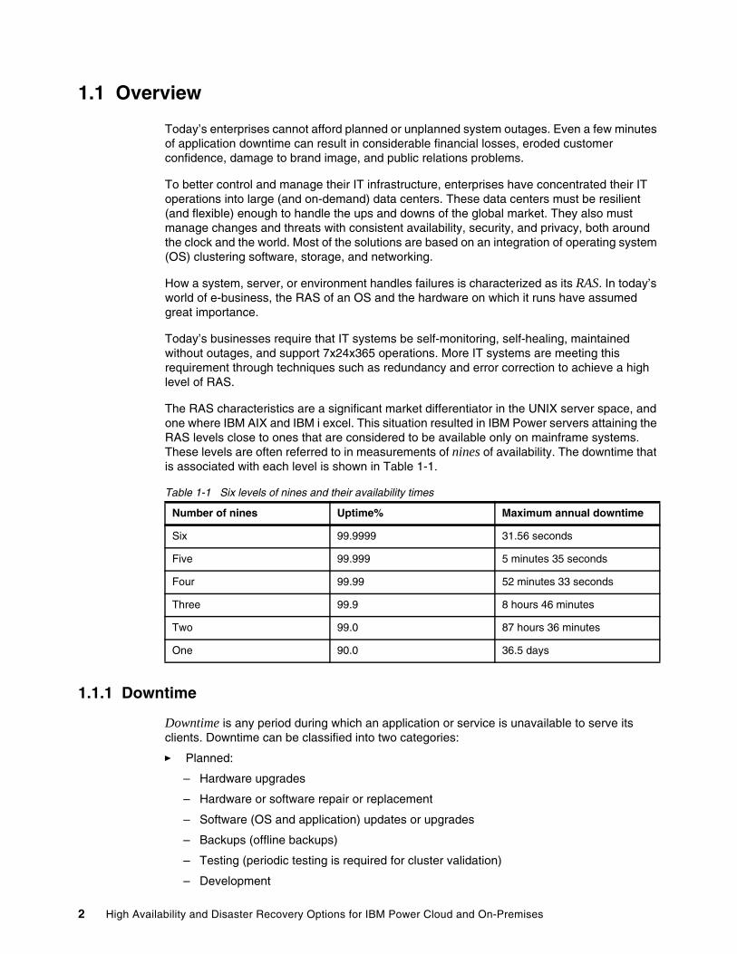
The RAS characteristics are a significant market differentiator in the UNIX server space, and one where IBM AIX and IBM i excel. This situation resulted in IBM Power servers attaining the RAS levels close to ones that are considered to be available only on mainframe systems. These levels are often referred to in measurements of nines of availability. The downtime that is associated with each level is shown in Table 1-1.
Table 1-1 Six levels of nines and their availability times
1.1.1 Downtime
Downtime is any period during which an application or service is unavailable to serve its clients. Downtime can be classified into two categories:
� Planned:
– Hardware upgrades
– Hardware or software repair or replacement
– Software (OS and application) updates or upgrades
– Backups (offline backups)
– Testing (periodic testing is required for cluster validation)
– Development
Number of nines Uptime% Maximum annual downtime
Six 99.9999 31.56 seconds
Five 99.999 5 minutes 35 seconds
Four 99.99 52 minutes 33 seconds
Three 99.9 8 hours 46 minutes
Two 99.0 87 hours 36 minutes
One 90.0 36.5 days
2 High Availability and Disaster Recovery Options for IBM Power Cloud and On-Premises
� Unplanned:
– Administrator errors
– Application failures
– Hardware failures
– OS errors
– Environmental disasters
Sometimes, downtime is associated with unplanned outage time. However, most downtime is the result of planned outages. Planned outages are necessary to help maintain systems to minimize the risk of an unplanned outage.
Uptime is a percentage of the amount of time that a system’s services are available, so anything less than 100% means that some downtime occurred. Any downtime, planned or unplanned, counts against total uptime. A planned and implemented high availability (HA) solution can help minimize, mask, or prevent planned maintenance that requires an outage.
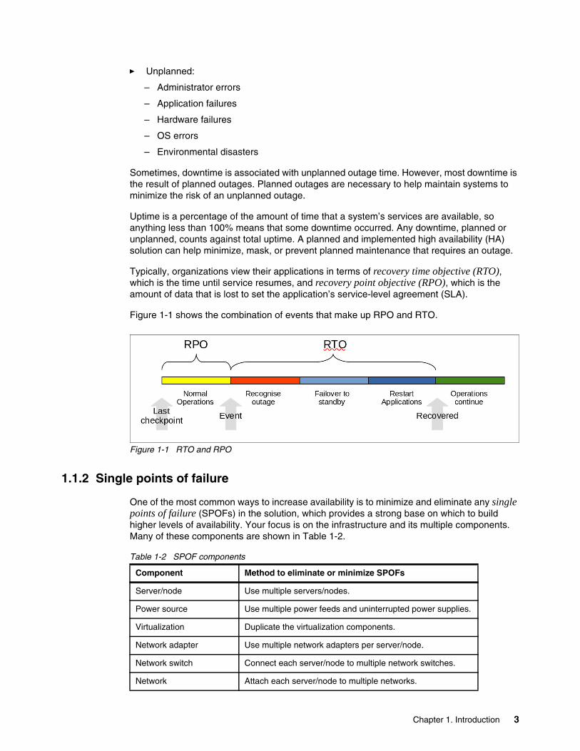
Typically, organizations view their applications in terms of recovery time objective (RTO), which is the time until service resumes, and recovery point objective (RPO), which is the amount of data that is lost to set the application’s service-level agreement (SLA).
Figure 1-1 shows the combination of events that make up RPO and RTO.
Figure 1-1 RTO and RPO
1.1.2 Single points of failure
One of the most common ways to increase availability is to minimize and eliminate any single points of failure (SPOFs) in the solution, which provides a strong base on which to build higher levels of availability. Your focus is on the infrastructure and its multiple components. Many of these components are shown in Table 1-2.
Table 1-2 SPOF components
Component Method to eliminate or minimize SPOFs
Server/node Use multiple servers/nodes.
Power source Use multiple power feeds and uninterrupted power supplies.
Virtualization Duplicate the virtualization components.
Network adapter Use multiple network adapters per server/node.
Network switch Connect each server/node to multiple network switches.
Network Attach each server/node to multiple networks.
Chapter 1. Introduction 3
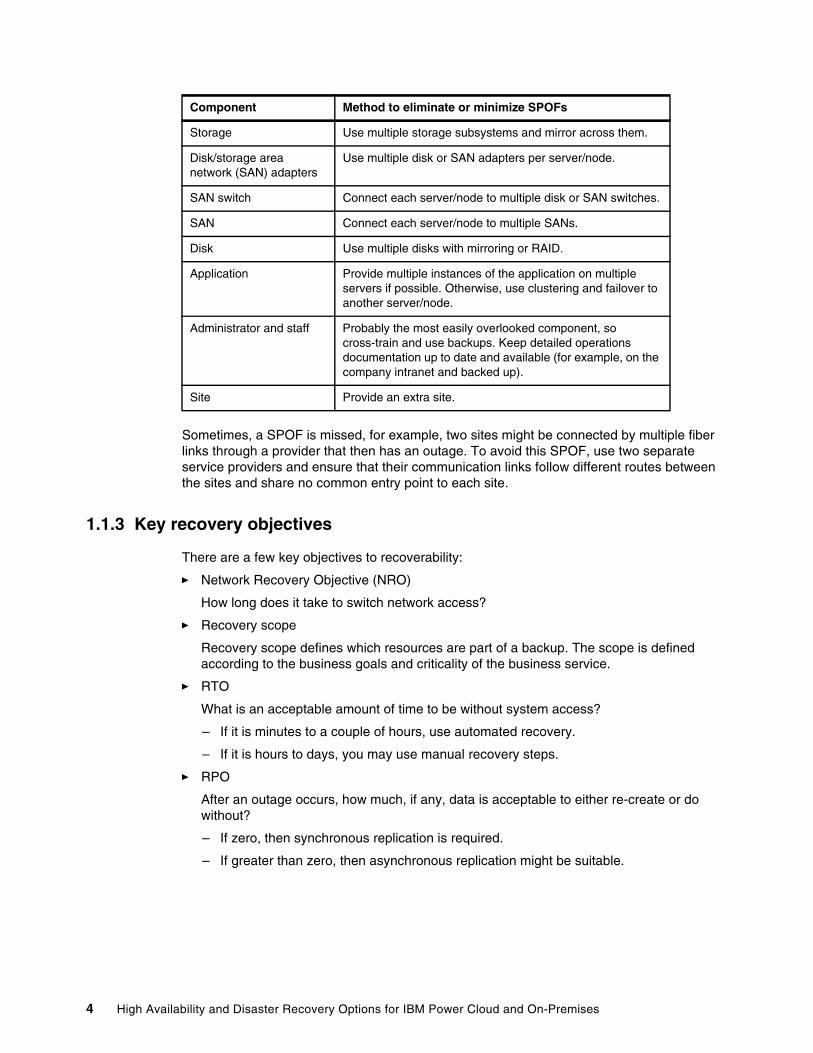
Sometimes, a SPOF is missed, for example, two sites might be connected by multiple fiber links through a provider that then has an outage. To avoid this SPOF, use two separate service providers and ensure that their communication links follow different routes between the sites and share no common entry point to each site.
1.1.3 Key recovery objectives
There are a few key objectives to recoverability:
� Network Recovery Objective (NRO)
How long does it take to switch network access?
� Recovery scope
Recovery scope defines which resources are part of a backup. The scope is defined according to the business goals and criticality of the business service.
� RTO
What is an acceptable amount of time to be without system access?
– If it is minutes to a couple of hours, use automated recovery.
– If it is hours to days, you may use manual recovery steps.
� RPO
After an outage occurs, how much, if any, data is acceptable to either re-create or do without?
– If zero, then synchronous replication is required.
– If greater than zero, then asynchronous replication might be suitable.
Storage Use multiple storage subsystems and mirror across them.
Disk/storage area network (SAN) adapters
Use multiple disk or SAN adapters per server/node.
SAN switch Connect each server/node to multiple disk or SAN switches.
SAN Connect each server/node to multiple SANs.
Disk Use multiple disks with mirroring or RAID.
Application Provide multiple instances of the application on multiple servers if possible. Otherwise, use clustering and failover to another server/node.
Administrator and staff Probably the most easily overlooked component, so cross-train and use backups. Keep detailed operations documentation up to date and available (for example, on the company intranet and backed up).
Site Provide an extra site.
Component Method to eliminate or minimize SPOFs
4 High Availability and Disaster Recovery Options for IBM Power Cloud and On-Premises
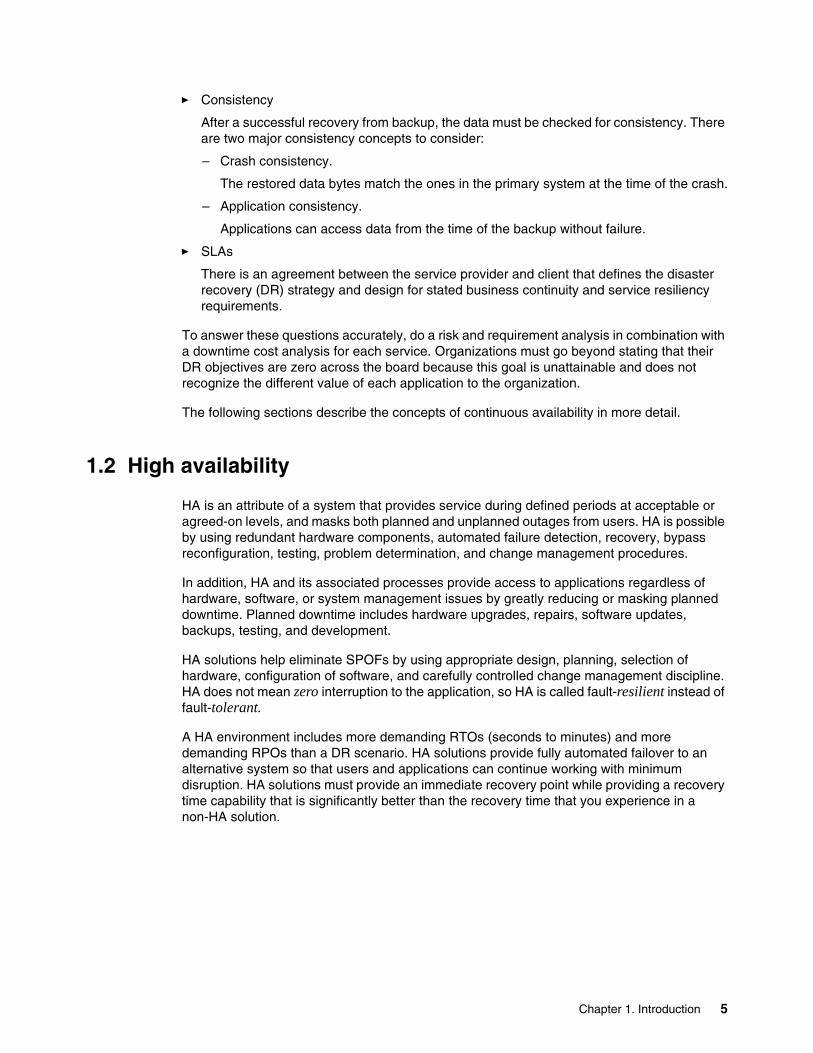
� Consistency
After a successful recovery from backup, the data must be checked for consistency. There are two major consistency concepts to consider:
– Crash consistency.
The restored data bytes match the ones in the primary system at the time of the crash.
– Application consistency.
Applications can access data from the time of the backup without failure.
� SLAs
There is an agreement between the service provider and client that defines the disaster recovery (DR) strategy and design for stated business continuity and service resiliency requirements.
To answer these questions accurately, do a risk and requirement analysis in combination with a downtime cost analysis for each service. Organizations must go beyond stating that their DR objectives are zero across the board because this goal is unattainable and does not recognize the different value of each application to the organization.
The following sections describe the concepts of continuous availability in more detail.
1.2 High availability
HA is an attribute of a system that provides service during defined periods at acceptable or agreed-on levels, and masks both planned and unplanned outages from users. HA is possible by using redundant hardware components, automated failure detection, recovery, bypass reconfiguration, testing, problem determination, and change management procedures.
In addition, HA and its associated processes provide access to applications regardless of hardware, software, or system management issues by greatly reducing or masking planned downtime. Planned downtime includes hardware upgrades, repairs, software updates, backups, testing, and development.
HA solutions help eliminate SPOFs by using appropriate design, planning, selection of hardware, configuration of software, and carefully controlled change management discipline. HA does not mean zero interruption to the application, so HA is called fault-resilient instead of fault-tolerant.
A HA environment includes more demanding RTOs (seconds to minutes) and more demanding RPOs than a DR scenario. HA solutions provide fully automated failover to an alternative system so that users and applications can continue working with minimum disruption. HA solutions must provide an immediate recovery point while providing a recovery time capability that is significantly better than the recovery time that you experience in a non-HA solution.
Chapter 1. Introduction 5
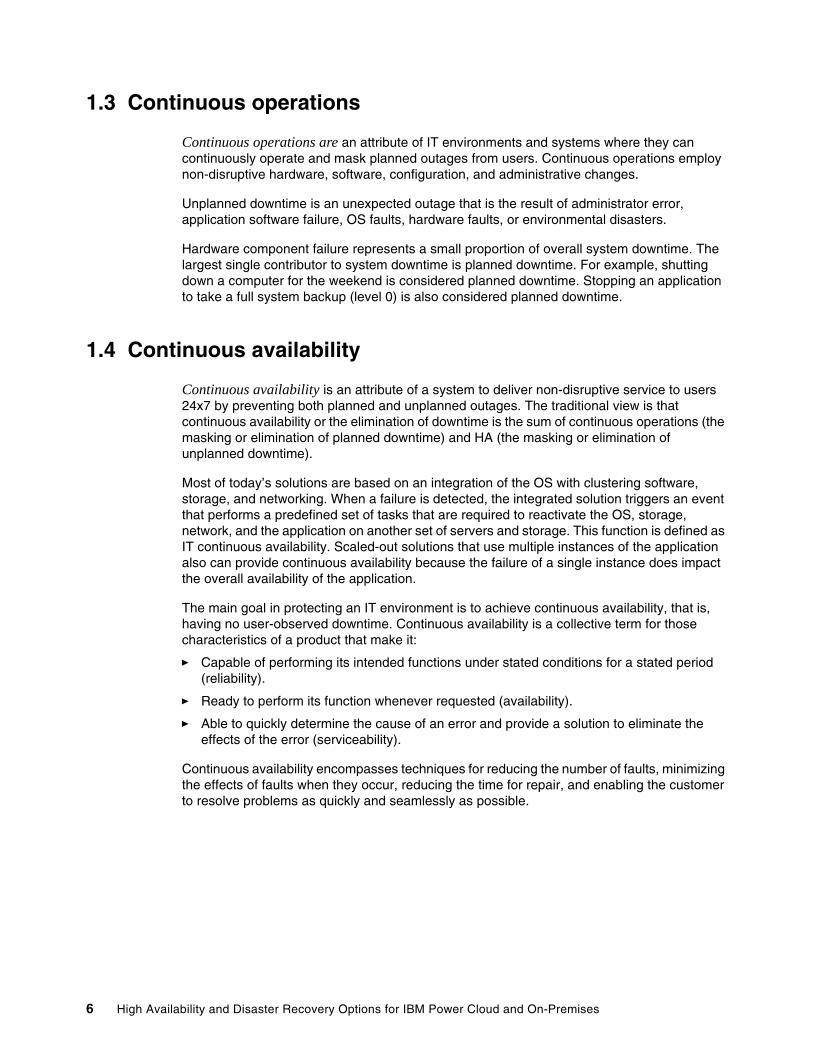
1.3 Continuous operations
Continuous operations are an attribute of IT environments and systems where they can continuously operate and mask planned outages from users. Continuous operations employ non-disruptive hardware, software, configuration, and administrative changes.
Unplanned downtime is an unexpected outage that is the result of administrator error, application software failure, OS faults, hardware faults, or environmental disasters.
Hardware component failure represents a small proportion of overall system downtime. The largest single contributor to system downtime is planned downtime. For example, shutting down a computer for the weekend is considered planned downtime. Stopping an application to take a full system backup (level 0) is also considered planned downtime.
1.4 Continuous availability
Continuous availability is an attribute of a system to deliver non-disruptive service to users 24x7 by preventing both planned and unplanned outages. The traditional view is that continuous availability or the elimination of downtime is the sum of continuous operations (the masking or elimination of planned downtime) and HA (the masking or elimination of unplanned downtime).
Most of today’s solutions are based on an integration of the OS with clustering software, storage, and networking. When a failure is detected, the integrated solution triggers an event that performs a predefined set of tasks that are required to reactivate the OS, storage, network, and the application on another set of servers and storage. This function is defined as IT continuous availability. Scaled-out solutions that use multiple instances of the application also can provide continuous availability because the failure of a single instance does impact the overall availability of the application.
The main goal in protecting an IT environment is to achieve continuous availability, that is, having no user-observed downtime. Continuous availability is a collective term for those characteristics of a product that make it:
� Capable of performing its intended functions under stated conditions for a stated period (reliability).
� Ready to perform its function whenever requested (availability).
� Able to quickly determine the cause of an error and provide a solution to eliminate the effects of the error (serviceability).
Continuous availability encompasses techniques for reducing the number of faults, minimizing the effects of faults when they occur, reducing the time for repair, and enabling the customer to resolve problems as quickly and seamlessly as possible.
6 High Availability and Disaster Recovery Options for IBM Power Cloud and On-Premises
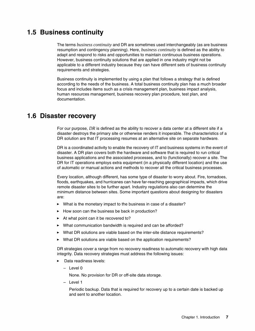
1.5 Business continuity
The terms business continuity and DR are sometimes used interchangeably (as are business resumption and contingency planning). Here, business continuity is defined as the ability to adapt and respond to risks and opportunities to maintain continuous business operations. However, business continuity solutions that are applied in one industry might not be applicable to a different industry because they can have different sets of business continuity requirements and strategies.
Business continuity is implemented by using a plan that follows a strategy that is defined according to the needs of the business. A total business continuity plan has a much broader focus and includes items such as a crisis management plan, business impact analysis, human resources management, business recovery plan procedure, test plan, and documentation.
1.6 Disaster recovery
For our purpose, DR is defined as the ability to recover a data center at a different site if a disaster destroys the primary site or otherwise renders it inoperable. The characteristics of a DR solution are that IT processing resumes at an alternative site on separate hardware.
DR is a coordinated activity to enable the recovery of IT and business systems in the event of disaster. A DR plan covers both the hardware and software that is required to run critical business applications and the associated processes, and to (functionally) recover a site. The DR for IT operations employs extra equipment (in a physically different location) and the use of automatic or manual actions and methods to recover all the critical business processes.
Every location, although different, has some type of disaster to worry about. Fire, tornadoes, floods, earthquakes, and hurricanes can have far-reaching geographical impacts, which drive remote disaster sites to be further apart. Industry regulations also can determine the minimum distance between sites. Some important questions about designing for disasters are:
� What is the monetary impact to the business in case of a disaster?
� How soon can the business be back in production?
� At what point can it be recovered to?
� What communication bandwidth is required and can be afforded?
� What DR solutions are viable based on the inter-site distance requirements?
� What DR solutions are viable based on the application requirements?
DR strategies cover a range from no recovery readiness to automatic recovery with high data integrity. Data recovery strategies must address the following issues:
� Data readiness levels:
– Level 0
None. No provision for DR or off-site data storage.
– Level 1
Periodic backup. Data that is required for recovery up to a certain date is backed up and sent to another location.
Chapter 1. Introduction 7
– Level 2
Ready to roll forward. In addition to periodic backups, data update logs are periodically sent to another location either by using physical media or electronically. The recovery point is up to the latest update log at the recovery site.
– Level 3
Roll forward or forward recover. A shadow copy of the data is maintained on disks at the recovery site. Data update logs are received and periodically applied to the shadow copy by using recovery utilities.
– Level 4
Real-time roll forward. Like roll-forward, except updates are transmitted and applied while they are being logged at the original site. This real-time transmission and application of log data does not impact transaction response time at the original site.
– Level 5
Real-time remote update. Both the original and the recovery copies of data are updated before sending the transaction response or completing a task.
� Site interconnection options:
– Level 0
None. There is no interconnection or transport of data between sites.
– Level 1
Manual transport. There is no interconnection. For transport of data between sites, dispatch, tracking, and receipt of data is managed manually.
– Level 2
Remote tape. Data is transported electronically to a remote tape. Dispatch and receipt are automatic. Tracking can be either automatic or manual.
– Level 3
Remote disk. Data is transported electronically to a remote disk. Dispatch, receipt, and tracking are all automatic.
� Recovery site readiness:
– Cold
A cold site is an environment with the proper infrastructure, but little or no data processing equipment. This equipment must be installed as the first step in the data recovery process. Both periodic backup and ready to roll forward data can be shipped from a storage location to this site when a disaster occurs.
– Warm
A warm site has data processing equipment that is installed and operational. This equipment is used for other data processing tasks until a disaster occurs. Data processing resources can be used to store data, such as logs. Recovery begins after the regular work of the site is shut down and backed up. Both periodic backup and ready to roll forward data can be stored at this site to expedite DR.
– Hot
A hot site has data processing equipment that is installed and operational, and the data can be restored either continually or regularly to reduce recovery time.
– Active-active
A subset of the applications is active in both sites at the same time.
8 High Availability and Disaster Recovery Options for IBM Power Cloud and On-Premises
There are many common things to account for in almost every DR solution, such as:
� Systems that are provisioned for DR are of a different type, size, and capacity than production.
� User and group permission problems.
� Application licenses that are tied to hardware.
� Some local HA options, such as multiple instances of an application, no longer exist at the DR site if the services are combined on the same server.
� Production applications that are tied to a specific network address or network name during installation.
� Node name and hostname conflicts between existing systems in the DR site and the new systems being implemented under the DR plan.
� Multiple implementation standards for various functional system types, such as stand-alone, HA, and DR.
� Networking name or address conflicts.
The best solution for avoiding networking conflicts during a DR implementation is to always ensure that each network address (TCP/IP) or name has a unique value across the enterprise. In organizations with multiple active data centers, network addresses (TCP/IP) from the production data center should not be failed over to the DR site. To do so requires reconfiguration of routers and switches, which can endanger the existing production systems running in the data center accepting the DR workload.
Therefore, the production applications should never be tied to or depend on a specific network TCP/IP address because in a disaster those network TCP/IP addresses change, which causes the applications to not work. Applications and regular users should never use or specify a network service by its TCP/IP address, and they should use only a symbolic name. Furthermore, the symbolic name that is used by applications and regular users should be only an alias that points to a hostname.
� Usernames.
Each person in an organization should be assigned a unique identifier across the enterprise that is assigned only to that person and retired when they leave the organization. This approach ensures a seamless audit trail when evaluating problems, issues, and actions. The username should consist of alphanumeric characters and be a valid structure for all systems within an organization so that each person has only one username. Specifying a username structure that works on all systems and provides enough variability can be a daunting task for organizations because they use many OSs, each with its own requirements for username structures, including password management.
� File system or mount point names.
To recover multiple instances of an application onto a single system in a DR scenario, each file system containing application files should have a unique mount point directory across the enterprise. The best way to achieve this configuration is to use the resource group name or a substring of the logical volume name as the top-level directory, considering that a file system mount point is required for each logical volume.
Other considerations for planning DR vary for each application environment. The connectivity options and the distance between sites also dictate what type of data replication options are available. There is a careful balance that is required between the bandwidth that is required and the latency that is encountered when traversing greater distance. Although technologies might support “unlimited” distance, it is not always possible or even feasible to implement it.
Chapter 1. Introduction 9
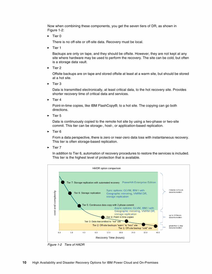
Now when combining these components, you get the seven tiers of DR, as shown in Figure 1-2:
� Tier 0
There is no off-site or off-site data. Recovery must be local.
� Tier 1
Backups are only on tape, and they should be offsite. However, they are not kept at any site where hardware may be used to perform the recovery. The site can be cold, but often is a storage data vault.
� Tier 2
Offsite backups are on tape and stored offsite at least at a warm site, but should be stored at a hot site.
� Tier 3
Data is transmitted electronically, at least critical data, to the hot recovery site. Provides shorter recovery time of critical data and services.
� Tier 4
Point-in-time copies, like IBM FlashCopy®, to a hot site. The copying can go both directions.
� Tier 5
Data is continuously copied to the remote hot site by using a two-phase or two-site commit. This tier can be storage-, host-, or application-based replication.
� Tier 6
From a data perspective, there is zero or near-zero data loss with instantaneous recovery. This tier is often storage-based replication.
� Tier 7
In addition to Tier 6, automation of recovery procedures to restore the services is included. This tier is the highest level of protection that is available.
Figure 1-2 Tiers of HADR
10 High Availability and Disaster Recovery Options for IBM Power Cloud and On-Premises
1.6.1 Hybrid cloud disaster recovery
A hybrid cloud application is a mix of on-premises, private, or public cloud platforms with orchestration between these distributed platforms and workloads to perform as a single business service. The flexibility, agility, scalability, and interoperability of a hybrid cloud environment creates a platform to run business-critical applications. The hybrid cloud applications that are built on IBM Power servers are known for their high performance and reliability. Although public cloud service providers ensure HA through data center redundancy, it is not always sufficient to protect from human or system errors or natural disasters hitting the services on a hybrid cloud application. Recent public cloud outages also point toward the need for a robust DR solution for your critical applications. Many protected environments, even IBM Power servers, can fail due to a single or multiple failures. To prepare for those scenarios, proactively define your DR strategy and design.
You can consider two possible approaches for hybrid cloud DR: application-driven and underlying technology driven. In the application-driven DR approach, assume that the application is built to be DR ready with replication enabled across multiple instances. In the technology driven DR approach, use data replication with DR site management or reprovisioning that is enabled through a recovery orchestrator.
1.7 Review of planning
Here are the critical components of successful HA or DR environments:
� Planning� Monitoring� Maintaining� Documenting� Testing
1.7.1 Planning
An important component of planning an overall HA or DR plan is to regularly review the organizations applications against the required RTO and RPO and ensure that the HADR solutions deliver those requirements. Chapter 2, “High availability disaster recovery concepts and solutions” on page 15 provides an overview of the options that are available and what they provide.
The other components are covered elsewhere, but include the following ones:
� Risk analysis and review of the types of possible disasters.
� Planning network throughput and latency while reducing the risks of both data centers being impacted by the same disaster.
� Planning resources for normal operations and during recovery from disaster.
1.7.2 Monitoring
Monitoring the entire environment is important to find and fix problems before they lead to an outage. For example, when a redundant component fails, the component is fixed or replaced to continue to provide the original level of redundancy. Undetected or unresolved problems can accumulate over time, which removes redundancy and ultimately leads to an outage.
Chapter 1. Introduction 11
1.7.3 Maintaining
Although problems that are found by monitoring often lead to maintenance, it is not the only component of maintaining an environment. Normal maintenance often includes the following items:
� Backups.� Installing OS updates.� Installing application updates.� User access and password management.� Old data and files cleanup.� Problem detection and fixes.� Security scans.
1.7.4 Documenting
Documenting can be a time-consuming task, but it is important during normal operations and especially in an emergency. Documentation can be done in various ways, and as a best practice, keep documentation on the company’s intranet when possible. Documentation must be constantly maintained, and there are often scripts and automated tasks that can help you keep system documentation current.
Another critical component of documentation is the post-outage review and update. After every incident, you can improve your organization’s HADR by learning from the experience, improving your monitoring so that the event will be captured, and updating your documentation, training, and testing.
1.7.5 Testing
All plans and solutions are worthless if they are never tested. All change and management procedures must be tested in a non-production environment before they are implemented in production. All HADR solutions must be methodically tested regularly. It is better to find a problem during planned testing than during an unplanned outage.
1.7.6 Comparing options
At a high level, the solutions that are presented in this publication apply equally to the following scenarios:
� HA with a data center (on-premises)� HADR across two data centers (on-premises)� HA within the cloud� HADR between on-premises and the cloud� HADR between two clouds (different providers or zones)
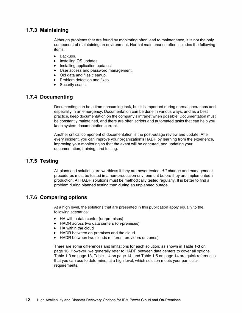
There are some differences and limitations for each solution, as shown in Table 1-3 on page 13. However, we generally refer to HADR between data centers to cover all options. Table 1-3 on page 13, Table 1-4 on page 14, and Table 1-5 on page 14 are quick references that you can use to determine, at a high level, which solution meets your particular requirements.
12 High Availability and Disaster Recovery Options for IBM Power Cloud and On-Premises
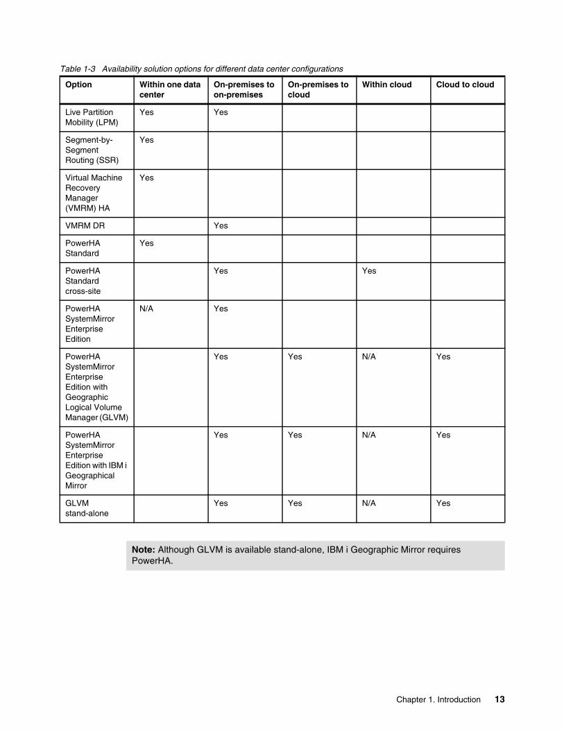
Table 1-3 Availability solution options for different data center configurations
Option Within one data center
On-premises to on-premises
On-premises to cloud
Within cloud Cloud to cloud
Live Partition Mobility (LPM)
Yes Yes
Segment-by-Segment Routing (SSR)
Yes
Virtual Machine Recovery Manager (VMRM) HA
Yes
VMRM DR Yes
PowerHA Standard
Yes
PowerHA Standard cross-site
Yes Yes
PowerHA SystemMirror Enterprise Edition
N/A Yes
PowerHA SystemMirror Enterprise Edition with Geographic Logical Volume Manager (GLVM)
Yes Yes N/A Yes
PowerHA SystemMirror Enterprise Edition with IBM i Geographical Mirror
Yes Yes N/A Yes
GLVM stand-alone
Yes Yes N/A Yes
Note: Although GLVM is available stand-alone, IBM i Geographic Mirror requires PowerHA.
Chapter 1. Introduction 13
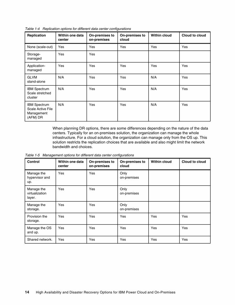
Table 1-4 Replication options for different data center configurations
When planning DR options, there are some differences depending on the nature of the data centers. Typically for an on-premises solution, the organization can manage the whole infrastructure. For a cloud solution, the organization can manage only from the OS up. This solution restricts the replication choices that are available and also might limit the network bandwidth and choices.
Table 1-5 Management options for different data center configurations
Replication Within one data center
On-premises to on-premises
On-premises to cloud
Within cloud Cloud to cloud
None (scale-out) Yes Yes Yes Yes Yes
Storage-managed
Yes Yes
Application-managed
Yes Yes Yes Yes Yes
GLVM stand-alone
N/A Yes Yes N/A Yes
IBM Spectrum Scale stretched cluster
N/A Yes Yes N/A Yes
IBM Spectrum Scale Active File Management (AFM) DR
N/A Yes Yes N/A Yes
Control Within one data center
On-premises to on-premises
On-premises to cloud
Within cloud Cloud to cloud
Manage the hypervisor and up.
Yes Yes Only on-premises
Manage the virtualization layer.
Yes Yes Only on-premises
Manage the storage.
Yes Yes Only on-premises
Provision the storage.
Yes Yes Yes Yes Yes
Manage the OS and up.
Yes Yes Yes Yes Yes
Shared network. Yes Yes Yes Yes Yes
14 High Availability and Disaster Recovery Options for IBM Power Cloud and On-Premises
Chapter 2. High availability disaster recovery concepts and solutions
This chapter describes some of the basic requirements for building a highly available disaster recovery (HADR) solution. Section 2.4, “Solutions” on page 29 looks at how this foundation is used by some of the many HADR solutions that are available. In a typical data center, a range of solutions is required because applications vary, for example, some have built-in availability, but each has its own service-level agreements (SLAs) and recovery times.
This chapter contains the following topics:
� 2.1, “High availability disaster recovery concepts” on page 16� 2.2, “High availability disaster recovery requirements” on page 17� 2.3, “Planning considerations” on page 27� 2.4, “Solutions” on page 29
2
© Copyright IBM Corp. 2022. 15
2.1 High availability disaster recovery concepts
The following concepts are used in this chapter:
Split-brain or split-cluster A cluster split-brain can occur when a subset of nodes in a cluster cannot communicate with the remaining nodes. Although it is possible for this situation to occur within the data center, it is far more likely to happen to a cluster across data centers due to the greater exposure of the interconnecting networks to potential risk.
In a split-brain situation, the two partitions have no knowledge of each other’s status, and each of them believe that the nodes in the other partition are offline. Therefore, each partition tries to bring online the other partition’s applications and access the shared resources, which is an action that is highly likely to result in lost or corrupted data on the shared storage.
Tie breaker or third site In HADR clusters, it is a best practice to use a tie breaker or a third site to prevent a split-brain situation. Although it is still important to avoid this situation for clusters within a single data center, it is far less likely because multiple communication paths connect all nodes in the cluster, which is a less common situation between sites.
The tie-breaker feature uses a tie-breaker resource to choose which partition survives and continues to operate when a cluster split-brain situation occurs. This feature prevents data corruption on the shared or replicated disks.
PowerHA SystemMirror uses tie-breaker disks or a Network File System (NFS) share file to act as the tie breaker and split-merge policies to control the behavior of the cluster.
Split policy When a split-brain situation occurs, each partition attempts to acquire the tie breaker by placing a lock on the tie-breaker disk or on the NFS file. The partition that holds the lock on the SCSI disk or reserves the NFS file wins, and the other loses.
All nodes in the winning partition continue to process cluster events, and all nodes in the losing partition attempt to recover according to the defined split and merge action plan. This plan most often implies either the restart of the cluster nodes or the restart of cluster services on those nodes.
Merge policy There are situations where, depending on the cluster split-brain policy, the cluster can have two partitions that run independent of each other. However, most often, it is a best practice to configure a merge policy that allows the partitions to operate together again after communications are restored between them.
16 High Availability and Disaster Recovery Options for IBM Power Cloud and On-Premises
In this second approach, when partitions that were part of the cluster are brought back online after the communication failure, they must be able to communicate with the partition that owns the tie breaker disk or NFS file. If a partition that is brought back online cannot communicate with the tie-breaker disk or the NFS file, it does not join the cluster. The tie-breaker device is released when all nodes in the configuration have rejoined the cluster.
The merge policy configuration must be the same type as the one for the split policy, for example, it uses an NFS-based tie breaker.
Synchronous replication Writes are committed at the remote storage before an acknowledgment can be returned to the application. This delay degrades the application performance and limits the distance between the application and the remote storage to around 80 - 120 km.
Asynchronous replication Writes are cached locally in some form of non-volatile storage and an acknowledgment is returned to the application. Later, the write is committed to the remote storage, and then the record is removed from the local cache.
Asynchronous mode allows for much greater distances between sites, smoother peaks in I/O, and a lower bandwidth network. However, in a disaster data will be lost, with the cache size representing the maximum amount of data that can potentially be lost.
2.2 High availability disaster recovery requirements
An underlying requirement is to remove all single points of failure (SPOFs) from the environment, which requires redundancy options for servers, networks, storage, data centers, and the surrounding infrastructure (people, printers, backups, and so on).
In this section, we examine the following items:
� Basic system requirements
� Network configuration
� Storage configurations
� Site requirements
� Cluster Aware AIX (CAA) for PowerHA SystemMirror
� Other prerequisites
Generally, applications can be broken down into two types:
� Scale-out or concurrent
� Clustered
Chapter 2. High availability disaster recovery concepts and solutions 17
Scale-out and concurrent solutions provide redundancy by using multiple instances, so the focus is on ensuring that the surrounding infrastructure provides client access to several application instances while ensuring that sufficient instances of the application are available to meet workload requirements.
Clustered solutions rely heavily on knowing the status of the infrastructure to keep the individual application available. The focus is on ensuring that the applications are online only when required while ensuring that they have consistent access to the data. If the cluster splits, then nodes on either side should not start to operate independently.
2.2.1 Basic system requirements
There are many different ways to build a highly available (HA) environment. This section describes a subset of options.
Mirrored architectureIn a mirrored architecture, you have identical or nearly identical physical components in each part of the data center. You can have this type of setup in a single room (although it is not recommended), in different rooms in the same building, or in different buildings.
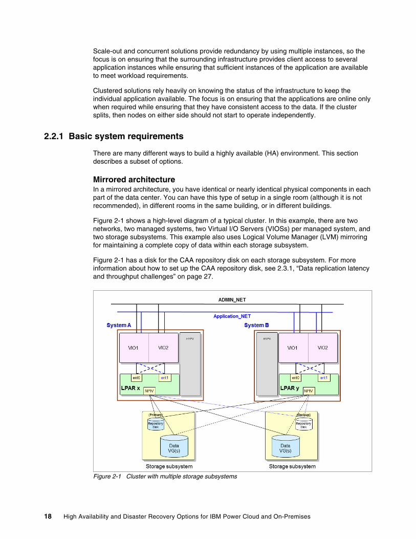
Figure 2-1 shows a high-level diagram of a typical cluster. In this example, there are two networks, two managed systems, two Virtual I/O Servers (VIOSs) per managed system, and two storage subsystems. This example also uses Logical Volume Manager (LVM) mirroring for maintaining a complete copy of data within each storage subsystem.
Figure 2-1 has a disk for the CAA repository disk on each storage subsystem. For more information about how to set up the CAA repository disk, see 2.3.1, “Data replication latency and throughput challenges” on page 27.
Figure 2-1 Cluster with multiple storage subsystems
18 High Availability and Disaster Recovery Options for IBM Power Cloud and On-Premises
2.2.2 Network configuration
This section focuses on the network considerations from an availability point of view and examines the following items:
� Types of network: Physical or virtual
� Network adapters
� Redundancy in networks
� Inter-site considerations
Physical or virtualUsing technologies such as Live Partition Mobility (LPM), Simplified Remote Restart (SRR) and Virtual Machine Recovery Manager (VMRM) require the environment to be fully virtualized. In clustered solutions such as PowerHA SystemMirror, although there are some configuration differences, they operate equally well in both physical or virtual environments.
Network adaptersNetwork redundancy has been traditionally provided by using dual-adapter networks. More recently, single logical adapters are used with their redundancy that is provided by multiple physical backing devices. This approach uses bonding (Etherchannel), failover (Network Interface Backup), virtualization (dual VIOSs and Shared Ethernet Adapters (SEAs)), or a combination thereof.
Redundancy in networksIn the past, redundant networks were common. Now, these networks are not as prevalent because improvements in the design and operations of the network hardware with the ability to have multiple paths introduced greater redundancy.
Intersite considerationsYou must ensure that the intersite connection does not become a SPOF. To accomplish this task, avoid the following items:
� A single provider
� A common entry point for client access to the applications at both sites
� A common entry or exit point for the intersite links
� Common intermediate points
Often different data centers use different subnets. and although they can be handled by PowerHA SystemMirror and VMRM DR, manual intervention might be required if other HA solutions are operated across sites.
This publication describes the importance of planning the network bandwidth and latency to meet the application response time requirements. What is equally important is to plan a bandwidth that is sufficient for both normal operations and the extra throughput that is required to recover and resynchronize a site after a disaster.
Chapter 2. High availability disaster recovery concepts and solutions 19
2.2.3 Storage configurations
This section describes different storage configurations.
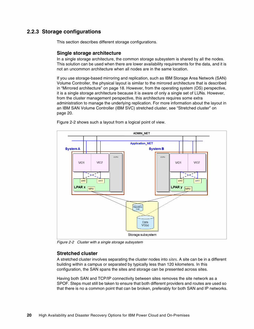
Single storage architectureIn a single storage architecture, the common storage subsystem is shared by all the nodes. This solution can be used when there are lower availability requirements for the data, and it is not an uncommon architecture when all nodes are in the same location.
If you use storage-based mirroring and replication, such as IBM Storage Area Network (SAN) Volume Controller, the physical layout is similar to the mirrored architecture that is described in “Mirrored architecture” on page 18. However, from the operating system (OS) perspective, it is a single storage architecture because it is aware of only a single set of LUNs. However, from the cluster management perspective, this architecture requires some extra administration to manage the underlying replication. For more information about the layout in an IBM SAN Volume Controller (IBM SVC) stretched cluster, see “Stretched cluster” on page 20.
Figure 2-2 shows such a layout from a logical point of view.
Figure 2-2 Cluster with a single storage subsystem
Stretched clusterA stretched cluster involves separating the cluster nodes into sites. A site can be in a different building within a campus or separated by typically less than 120 kilometers. In this configuration, the SAN spans the sites and storage can be presented across sites.
Having both SAN and TCP/IP connectivity between sites removes the site network as a SPOF. Steps must still be taken to ensure that both different providers and routes are used so that there is no a common point that can be broken, preferably for both SAN and IP networks.
20 High Availability and Disaster Recovery Options for IBM Power Cloud and On-Premises
Another main concern is having redundant storage and verifying that the data within the storage devices is synchronized across sites. The following section presents a method for synchronizing the shared data.
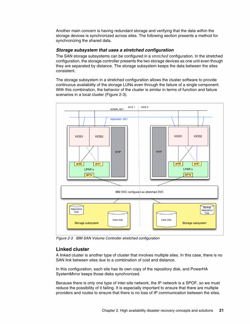
Storage subsystem that uses a stretched configurationThe SAN storage subsystems can be configured in a stretched configuration. In the stretched configuration, the storage controller presents the two storage devices as one unit even though they are separated by distance. The storage subsystem keeps the data between the sites consistent.
The storage subsystem in a stretched configuration allows the cluster software to provide continuous availability of the storage LUNs even through the failure of a single component. With this combination, the behavior of the cluster is similar in terms of function and failure scenarios in a local cluster (Figure 2-3).
Figure 2-3 IBM SAN Volume Controller stretched configuration
Linked clusterA linked cluster is another type of cluster that involves multiple sites. In this case, there is no SAN link between sites due to a combination of cost and distance.
In this configuration, each site has its own copy of the repository disk, and PowerHA SystemMirror keeps those disks synchronized.
Because there is only one type of inter-site network, the IP network is a SPOF, so we must reduce the possibility of it failing. It is especially important to ensure that there are multiple providers and routes to ensure that there is no loss of IP communication between the sites.
Chapter 2. High availability disaster recovery concepts and solutions 21
For more information about linked clusters, see IBM PowerHA SystemMirror 7.1.2 Enterprise Edition for AIX, SG24-8106.
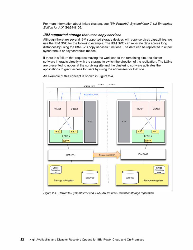
IBM supported storage that uses copy servicesAlthough there are several IBM supported storage devices with copy services capabilities, we use the IBM SVC for the following example. The IBM SVC can replicate data across long distances by using the IBM SVC copy services functions. The data can be replicated in either synchronous or asynchronous modes.
If there is a failure that requires moving the workload to the remaining site, the cluster software interacts directly with the storage to switch the direction of the replication. The LUNs are presented to nodes at the surviving site and the clustering software activates the applications to grant access to users by using the addresses for that site.
An example of this concept is shown in Figure 2-4.
Figure 2-4 PowerHA SystemMirror and IBM SAN Volume Controller storage replication
22 High Availability and Disaster Recovery Options for IBM Power Cloud and On-Premises
2.2.4 Site requirements
There are some differences between using on-premises solutions compared to solutions in the cloud.
Other site planning should include the following items:
� Staff access and facilities at both sites.
� All the associated infrastructure that is required by the application.
� Availability of critical information, documents, backups, and licenses.
� Distance between sites greater than what is affected by envisaged disasters.
� Access to backups.
� Access to qualified staff and documentation.
� Access to contracts and support services.
� Outages for maintenance, which should be at least quarterly for the next 2 years.1 If you do not do this task, you should run a test plan.
� Access to licenses and support contracts.
� Test PowerHA SystemMirror by using a test tool (script your own test plan). VMRM DR allows for a DR rehearsal.
IBM Power Virtual Server offeringThe IBM Power Virtual Server offering provides a secure and scalable server virtualization environment that is built on the IBM Cloud platform for on-demand provisioning. The IBM Power Virtual Servers are in IBM data centers, which are distinct from the IBM Cloud servers, with separate networks and direct-attached storage. The environment is in its own pod, and the internal networks are fenced but offer connectivity options to meet customer requirements. This infrastructure design enables IBM Power Virtual Server to maintain key enterprise software certification and support because the IBM Power Virtual Server architecture is identical to the certified on-premises infrastructure. The virtual servers, also known as logical partitions (LPARs), run on IBM Power hardware with the PowerVM hypervisor.
1 Set an aspirational target and expect the business to negotiate it back.
Chapter 2. High availability disaster recovery concepts and solutions 23
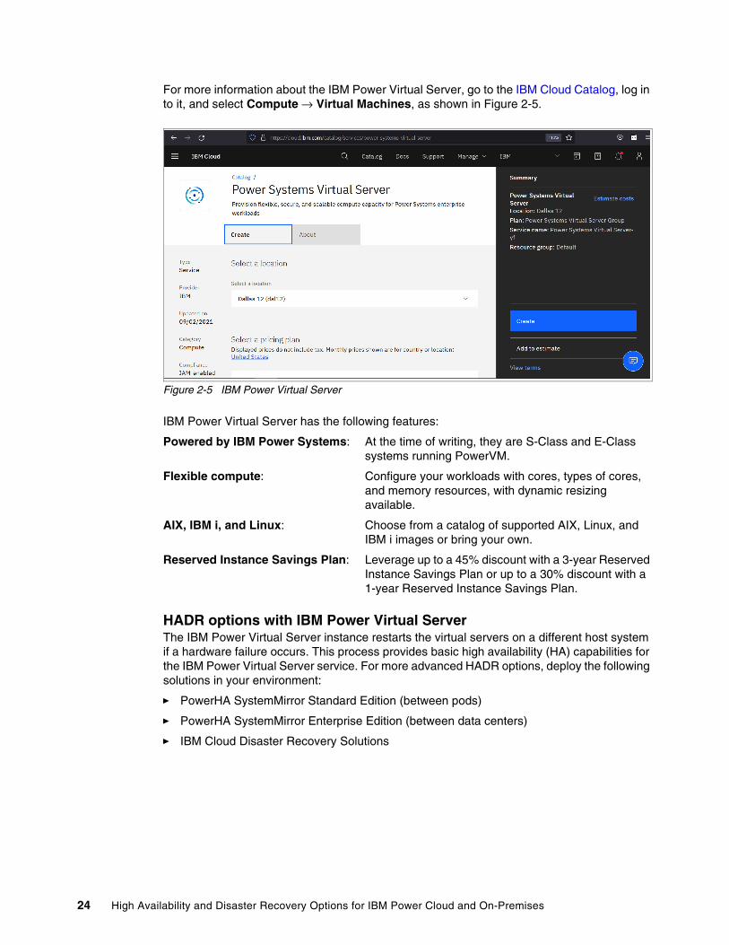
For more information about the IBM Power Virtual Server, go to the IBM Cloud Catalog, log in to it, and select Compute → Virtual Machines, as shown in Figure 2-5.
Figure 2-5 IBM Power Virtual Server
IBM Power Virtual Server has the following features:
Powered by IBM Power Systems: At the time of writing, they are S-Class and E-Class systems running PowerVM.
Flexible compute: Configure your workloads with cores, types of cores, and memory resources, with dynamic resizing available.
AIX, IBM i, and Linux: Choose from a catalog of supported AIX, Linux, and IBM i images or bring your own.
Reserved Instance Savings Plan: Leverage up to a 45% discount with a 3-year Reserved Instance Savings Plan or up to a 30% discount with a 1-year Reserved Instance Savings Plan.
HADR options with IBM Power Virtual ServerThe IBM Power Virtual Server instance restarts the virtual servers on a different host system if a hardware failure occurs. This process provides basic high availability (HA) capabilities for the IBM Power Virtual Server service. For more advanced HADR options, deploy the following solutions in your environment:
� PowerHA SystemMirror Standard Edition (between pods)
� PowerHA SystemMirror Enterprise Edition (between data centers)
� IBM Cloud Disaster Recovery Solutions
24 High Availability and Disaster Recovery Options for IBM Power Cloud and On-Premises
IBM Cloud Disaster Recovery SolutionsIBM Cloud offers built-in capabilities and services for business continuity, resiliency, and security. IBM Cloud Disaster Recovery Solutions are categorized into three major areas:
� Management: Improve the management of infrastructure, apps, processes, and entire cloud environments.
� Migration: Move existing applications and data to the cloud with a portfolio of disaster recovery (DR) focused migration tools and services.
� Storage: Scale capacity without interruption and deploy globally to achieve higher application performance.
IBM Backup as a ServiceIBM Backup as a Service (BUaaS) from IBM offers fully managed, end-to-end data protection and data backup in a security-rich environment. Its benefits include:
� Reliable data protection that complies with government and industry regulations.
� Scalability based on your business needs.
� Remote management and operation.
� Monitoring solutions to ensure the health of data protection.
IBM Resiliency ServicesIBM offers a full range of readily deployable services, solutions, and technologies for data protection and recovery:
� Security & Resiliency Consulting Services
� Disaster Recovery as a Service (DRaaS) for hybrid platform recovery
� Data Protection with BUaaS
� Cybersecurity and recovery
� Data center services
IBM Resiliency Disaster Recovery as a ServiceIBM Resiliency DRaaS offers continuous business resiliency of applications, infrastructure, data, and cloud systems with health monitoring and comprehensive DR services. Its benefits include:
� A less expensive operating expenses (OpEx) based solution compared to a self-managed on-premises model
� Reliable DR orchestration with automation
� Risk-based approach to protect critical IT services
� Data-driven service environment for testing DR, patches, and upgrades
MigrationThis section provides information about a few migration solutions options.
IBM Spectrum Protect PlusIBM Spectrum Protect Plus is a modern data resilience solution that provides recovery, replication, retention, and reuse for virtual machines (VMs), databases, applications, file systems, software as a service (SaaS) workloads, and containers in hybrid cloud environment.
Chapter 2. High availability disaster recovery concepts and solutions 25
Its benefits include:
� Easy to use and manage with SLA-based policies, role-based access control (RBAC), and drill-down dashboards.
� Simple deployment as a virtual appliance or container application and easy to maintain with the agentless architecture.
� Seamless integration and data access by using RESTful APIs.
� Supports data backup, recovery, and replication for VMs, Windows file systems, databases, applications, SaaS workloads and containers; and data retention and recovery on both on-premises and cloud object storage.
� Available on IBM Cloud, Amazon Web Services, and Microsoft Azure marketplaces.
Veeam on IBM cloudVeeam on IBM Cloud can deliver reliable backup and predictable DR for virtual and physical workloads, across your data center and the cloud. Its benefits include:
� Supported by no-cost networking that is available among more than 60 global data centers for replication.
� Supports on-premises and on cloud backup and recovery.
� Available as software to use or as a service model (SaaS and Backend as a Service (BaaS)).
� Long-term, low-cost retention options with IBM Cloud Object Storage (IBM Cloud Object Storage).
Zerto on IBM CloudZerto provides DR and cloud mobility within a single, simple, and scalable solution. Its benefits include:
� By using agentless, nondisruptive continuous data replication with journaling instead of snapshots, Zerto helps to deliver an accelerated recovery time objective (RTO) in minutes and a recovery point objective (RPO) in seconds.
� A high-speed global network backbone ensures resiliency with a multi-site IBM Cloud DR environment without added cost.
� Easy to manage with application-consistent recovery.
� Flexible SDDC and hardware configurations that can be automatically deployed.
StorageThis section provides information about a few storage solutions options.
Actifio GO on IBM CloudActifio GO on IBM Cloud is the next-generation, multi-cloud Copy Data Management SaaS solution that enables customers to back up enterprise workloads (VMware, Hyper-V, Physical Servers, SAP HANA, Oracle, SQL Server, and so on) directly to IBM Cloud while being able to instantly access the backup images within their data center.
IBM Cloud BackupIBM Cloud Backup is a full-featured, automated, and agent-based backup and recovery system that is managed through the IBM Cloud Backup WebCC browser utility. Its benefits include:
� Implement and monitor backup policies from anywhere by using a web-based GUI.
� You can choose an IBM data center or keep the backup outside the network.
26 High Availability and Disaster Recovery Options for IBM Power Cloud and On-Premises
� Recover from more than one facility by using multi-vaulting capabilities.
� Scheduled backup with intelligent compression of data.
� End-to-end encryption with Deltapro Deduplication.
� Restoration options from a previous backup or available multiple other recovery points.
IBM Cloud Object StorageIBM Cloud Object Storage is a flexible, cost-effective, and scalable cloud storage for unstructured data. Its benefits include:
� Less expensive because you can save costs that are related to server, power, and data center space requirements.
� Streamlined storage environment for increased agility and reduced downtime.
� Supports exponential data growth and built-in high-speed file transfer capabilities.
� Enhanced data security with role-based policies and access permissions.
2.3 Planning considerations
This section examines general planning considerations when planning HADR configurations.
2.3.1 Data replication latency and throughput challenges
This section describes data replication latency and throughput challenges.
Network latencyNetwork latency is the time that it takes for messages to go across the network. Even when there is plenty of network bandwidth, it still takes a finite amount of time for the bits to travel over the inter-site link. The speed of the network is limited by the quality of the switches and the laws of physics, and the network latency is proportional to the distance between the sites. Even if a network can transmit data at a rate of 120 kilometers per millisecond, it still adds up over a long distance.
For example, if the sites are 60 km apart, all I/O must travel 60 km from the application to the remote storage. After the remote storage is updated, the result of the I/O request must travel 60 km back to the application. This 120 km round trip adds about 1 millisecond to each I/O request, and this time can be much greater depending on the number and quality of routers or gateways that are traversed. Suppose that the sites are 4000 km apart, so each I/O request requires an 8000 km round trip, adding approximately 67 milliseconds to each I/O. The resulting application response time is in most cases unacceptable.
So, depending on the application, synchronous mirroring is the only practical approach, and for metro distances, that is in the order of 100 km or less. Greater distances typically necessitate asynchronous replication.
Network throughputAnother limitation on the operation of a DR site is the network bandwidth, which you can think of as the diameter of the pipe. The bigger the diameter, the more data that can be sent, but if the diameter is insufficient, then the data backs up until the flow is reduced, which adds to the latency in the I/O or fills the cache faster if you use asynchronous replication.
Chapter 2. High availability disaster recovery concepts and solutions 27
Planning for the bandwidth to be sufficient to meet the peaks in your I/O also might mean that an expensive network is sitting idle for most of the time if peaks are rare, but if the bandwidth is insufficient for peak I/O, then the application performance suffers.
Planning both bandwidth and latencyPlanning for latency is relatively simple, and after the sites are selected, they can be affected only by the quality of the network hardware. The application performance and user acceptance are the final arbiters in what is workable, and the I/O peak must not exceed the bandwidth of the network.
Planning bandwidth is more difficult because the bandwidth must be sufficient for normal operations and recovery requirements. If there is a disaster, after recovery happens, the networks, depending on the topology, might have to support the extra activity as users catch up with lost processing and the system refreshes stale data at the recovery site.
2.3.2 Data divergence and recovery planning
Typically, data divergence and recovery planning are experienced if there is loss of access to the active site when asynchronous or time-interval shipping of data is used. The organization must decide whether to move production to the alternative data center while using old data or whether waiting for the recovery of the failed active site falls within acceptable limits.
If operations continue at the alternative site, one of the following decisions must be made when the failed site is recovered and if the lost data can be recovered:
� Move operations back to the recovered site and not recover the data that is cached there.
� Move operations back to the recovered site by using the data there and discard the data that was created while running on the alternative site.
� Attempt to recover the cached data while using the recent data from the alternative site.
To make this decision, the organization must understand the following items:
� The amount of data that can be lost and its potential value.
� Alternative (manual) methods to recover the data.
� Site recovery time.
� Whether the failure is localized or does it apply to the whole data center, and if localized, what is the cost in moving all operations to the alternative site?
A good test plan, which is regularly run, helps with planning and training staff in the procedures.
2.3.3 Quorum sites
Many automated DR solutions must avoid creating a split-brain scenario due to the real possibility of losing or corrupting data. If the nodes in the two data centers lose contact, then the clustering software uses the quorum site (often called the third site or “laptop solution”) to determine which site should continue to operate.
The quorum site often has a disk device (Fibre Channel or iSCSI) or file in a network shared file system. Setting a lock on this object determines the surviving site.
28 High Availability and Disaster Recovery Options for IBM Power Cloud and On-Premises
2.4 Solutions
Over the last 10 years, IT operations have evolved to the point where critical applications are rarely hosted on the same frame (server) or in many cases in the same data center. However, this development tends to be more piecemeal rather than being driven by a detailed review. A detailed review examines the application requirements for HADR and then matches these requirements to the solutions that are available across the whole infrastructure.
For many years, IBM has been recognized as a leader in HADR solutions for workloads on IBM POWER® processor-based systems that meet the availability requirements of critical enterprise applications. In the recent years, the portfolio expanded to include protection for “less critical” applications in the data center. These applications are ones that can afford a slightly longer outage or have less stringent requirements around data loss. However, if you are looking for a less complex and lower-cost HADR solution, IBM now has many LPAR restart options (for more information, see “LPAR and virtual machine restart options” on page 62).
It is worth noting that the ITIC 2020 Reliability poll2 found that 87% of respondents consider 99.99% (52.56 minutes) of unplanned per server/per annum downtime to be the minimum acceptable level of reliability for mission-critical servers and applications, which is coupled with a reported increase in mission-critical business workloads by an average of 15% - 36% over the last three years. The same survey deals with the estimated costs of outages, while not under consideration here, must be accounted for when pricing your HADR solutions.
Now that IBM has a more comprehensive portfolio of HADR solutions, it is a good time to review what is available, what has changed, and how these options match your application availability requirements.
Although the primary focus of HADR solutions is to work around failures in the infrastructure, these tools are equally useful in managing maintenance and upgrade tasks. For example, PowerHA SystemMirror includes a tool on AIX to manage interim fixes and Service Packs across the cluster. Over the last few years, PowerHA SystemMirror development has focused on its ease of use, and it successfully countered the old and often inaccurate perception that PowerHA SystemMirror is difficult to manage.
Typically, organizations have a range of applications with related (but different) SLAs. For this situation, IBM has many solutions that can either work together or independently to meet your different SLAs and the different OSs that might be running in your IBM Power environment.
Addressing the cost of these solutions, which in most cases includes the duplication of expensive infrastructure, is not easy. However, to be prepared, an organization must be able to calculate a realistic cost to their business of some of the more common failure scenarios. Fortunately, the other side of the equation, the setup cost, is becoming easier to control by using some of the newer features of the products. For example, licenses now are activated only when needed, and resources can be freed as required by automating the shutdown of less critical workloads.
This section examines the options that are available to replicate the application data and to manage the application through building availability around the management of either the LPAR or the application. Availability can also be provided by scaling-out the application within the data center or across data centers.
2 https://www.ibm.com/downloads/cas/DV0XZV6R
Chapter 2. High availability disaster recovery concepts and solutions 29
The storage- and application-managed replication solutions include:
� Storage-managed replication solutions
� Application replication solutions
� Geographic Logical Volume Manager (GLVM)
� IBM i Geographic Mirroring
� IBM Spectrum Scale stretched cluster
� IBM Spectrum Scale Active File Management (AFM) DR
The options to manage the LPAR availability include:
� LPM, although it is more of a useful tool for administrators to move workloads for maintenance and some types of failure
� SRR
� IBM VMRM HA for the management of SRR
� IBM VMRM DR, which evolved from IBM Geographically Dispersed Resiliency (GDR) for IBM Power
The clustering options to manage application availability include:
� IBM Tivoli® System Automation for Multiplatform (AIX and Linux)
� PowerHA SystemMirror Standard Edition for AIX and i
� PowerHA SystemMirror Enterprise Edition for AIX and i
The scale-out option is Red Hat OpenShift.
2.4.1 Introducing data replication options
In general, data replication is a process that provides multiple copies of data, often across sites for HADR purposes. There are many ways to replicate data, such as:
� Storage
� Application
� Server and OS
This section covers options in each of these areas but in no way fully encompasses all options that are available today. We focus primarily on the options that are available for IBM Power servers. Many of these options can be used in combination with other HA management options, like PowerHA SystemMirror and VMRM.
Storage optionsThe following section primarily covers storage-based replication options that are available from IBM storage. There might be comparable options from other vendors.
IBM Spectrum Virtualize optionsHere are the details of each data replication option that is provided by IBM Spectrum Virtualize, formerly known as IBM Storwize®, and originally known as code from IBM SVC.
The IBM Spectrum Virtualize system combines software and hardware into a comprehensive, modular appliance that provides symmetric virtualization.
30 High Availability and Disaster Recovery Options for IBM Power Cloud and On-Premises
Symmetric virtualization is achieved by creating a pool of managed disks (MDisks) from the attached storage systems and optional SAS expansion enclosures. Volumes can be created in a pool for use by attached host systems. System administrators can view and access a common pool of storage on the SAN or local area network (LAN). This function helps administrators to use storage resources more efficiently and provides a common base of advanced functions for IBM storage and many heterogeneous storage environments.
IBM Spectrum Virtualize offers many functions and features, but for this document we focus on the Copy Services function. For more information about all features and functions,see IBM Documentation.
IBM FlashCopy FlashCopy makes an instant, point-in-time copy from a source volume to a target volume. Although this task often is performed within the same storage unit, virtual storage makes it possible to create the copies across separate storage units.
Some of the reasons for using FlashCopy to make copies of data are:
� Backup processing
� Data mining
� Creating an environment for testing
� Creating an environment for development
� Creating data for reporting
� Archiving
In its basic mode, the FlashCopy function creates copies of content on a source volume to a target volume in a mapping. The function associates a source volume and a target volume in a mapping. If data exists on the target volume, that data is replaced by the copied data. After the copy operation completes, the target volumes contain the contents of the source volumes as they existed at a single point in time unless target writes were processed.
FlashCopy is sometimes described as an instance of a time-zero copy (T 0) or point-in-time copy technology. Although the copy operation takes some time to complete, the resulting data on the target volume is presented so that the copy appears to have occurred immediately, and all data is available immediately. However, if needed, data that is still in the process of being copied can be accessed from the source.
Chapter 2. High availability disaster recovery concepts and solutions 31
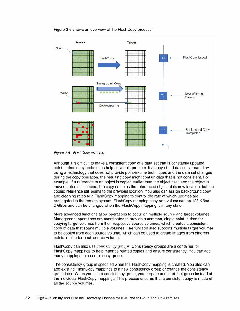
Figure 2-6 shows an overview of the FlashCopy process.
Figure 2-6 FlashCopy example
Although it is difficult to make a consistent copy of a data set that is constantly updated, point-in-time copy techniques help solve this problem. If a copy of a data set is created by using a technology that does not provide point-in-time techniques and the data set changes during the copy operation, the resulting copy might contain data that is not consistent. For example, if a reference to an object is copied earlier than the object itself and the object is moved before it is copied, the copy contains the referenced object at its new location, but the copied reference still points to the previous location. You also can assign background copy and cleaning rates to a FlashCopy mapping to control the rate at which updates are propagated to the remote system. FlashCopy mapping copy rate values can be 128 KBps - 2 GBps and can be changed when the FlashCopy mapping is in any state.
More advanced functions allow operations to occur on multiple source and target volumes. Management operations are coordinated to provide a common, single point-in-time for copying target volumes from their respective source volumes, which creates a consistent copy of data that spans multiple volumes. The function also supports multiple target volumes to be copied from each source volume, which can be used to create images from different points in time for each source volume.
FlashCopy can also use consistency groups. Consistency groups are a container for FlashCopy mappings to help manage related copies and ensure consistency. You can add many mappings to a consistency group.
The consistency group is specified when the FlashCopy mapping is created. You also can add existing FlashCopy mappings to a new consistency group or change the consistency group later. When you use a consistency group, you prepare and start that group instead of the individual FlashCopy mappings. This process ensures that a consistent copy is made of all the source volumes.
32 High Availability and Disaster Recovery Options for IBM Power Cloud and On-Premises
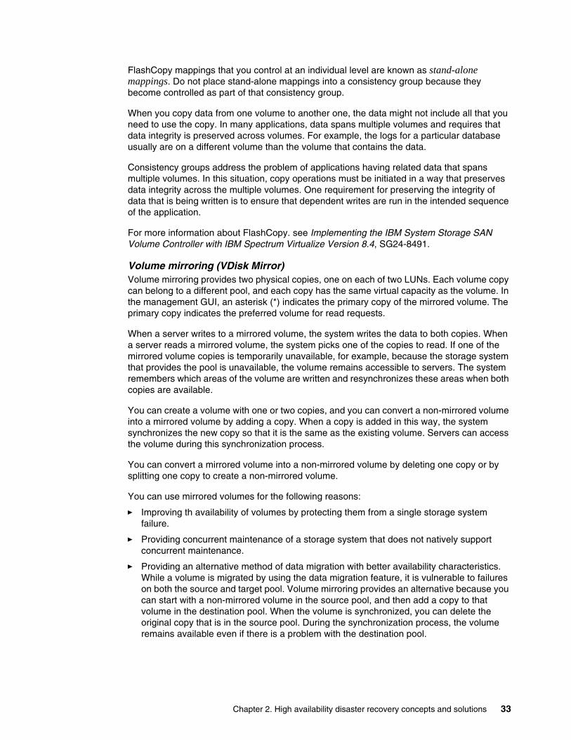
FlashCopy mappings that you control at an individual level are known as stand-alone mappings. Do not place stand-alone mappings into a consistency group because they become controlled as part of that consistency group.
When you copy data from one volume to another one, the data might not include all that you need to use the copy. In many applications, data spans multiple volumes and requires that data integrity is preserved across volumes. For example, the logs for a particular database usually are on a different volume than the volume that contains the data.
Consistency groups address the problem of applications having related data that spans multiple volumes. In this situation, copy operations must be initiated in a way that preserves data integrity across the multiple volumes. One requirement for preserving the integrity of data that is being written is to ensure that dependent writes are run in the intended sequence of the application.
For more information about FlashCopy. see Implementing the IBM System Storage SAN Volume Controller with IBM Spectrum Virtualize Version 8.4, SG24-8491.
Volume mirroring (VDisk Mirror)Volume mirroring provides two physical copies, one on each of two LUNs. Each volume copy can belong to a different pool, and each copy has the same virtual capacity as the volume. In the management GUI, an asterisk (*) indicates the primary copy of the mirrored volume. The primary copy indicates the preferred volume for read requests.
When a server writes to a mirrored volume, the system writes the data to both copies. When a server reads a mirrored volume, the system picks one of the copies to read. If one of the mirrored volume copies is temporarily unavailable, for example, because the storage system that provides the pool is unavailable, the volume remains accessible to servers. The system remembers which areas of the volume are written and resynchronizes these areas when both copies are available.
You can create a volume with one or two copies, and you can convert a non-mirrored volume into a mirrored volume by adding a copy. When a copy is added in this way, the system synchronizes the new copy so that it is the same as the existing volume. Servers can access the volume during this synchronization process.
You can convert a mirrored volume into a non-mirrored volume by deleting one copy or by splitting one copy to create a non-mirrored volume.
You can use mirrored volumes for the following reasons:
� Improving th availability of volumes by protecting them from a single storage system failure.
� Providing concurrent maintenance of a storage system that does not natively support concurrent maintenance.
� Providing an alternative method of data migration with better availability characteristics. While a volume is migrated by using the data migration feature, it is vulnerable to failures on both the source and target pool. Volume mirroring provides an alternative because you can start with a non-mirrored volume in the source pool, and then add a copy to that volume in the destination pool. When the volume is synchronized, you can delete the original copy that is in the source pool. During the synchronization process, the volume remains available even if there is a problem with the destination pool.
Chapter 2. High availability disaster recovery concepts and solutions 33
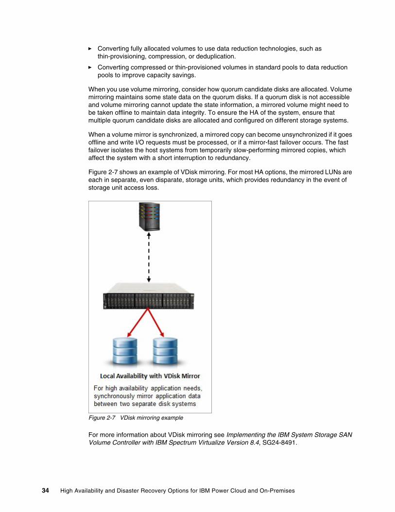
� Converting fully allocated volumes to use data reduction technologies, such as thin-provisioning, compression, or deduplication.
� Converting compressed or thin-provisioned volumes in standard pools to data reduction pools to improve capacity savings.
When you use volume mirroring, consider how quorum candidate disks are allocated. Volume mirroring maintains some state data on the quorum disks. If a quorum disk is not accessible and volume mirroring cannot update the state information, a mirrored volume might need to be taken offline to maintain data integrity. To ensure the HA of the system, ensure that multiple quorum candidate disks are allocated and configured on different storage systems.
When a volume mirror is synchronized, a mirrored copy can become unsynchronized if it goes offline and write I/O requests must be processed, or if a mirror-fast failover occurs. The fast failover isolates the host systems from temporarily slow-performing mirrored copies, which affect the system with a short interruption to redundancy.
Figure 2-7 shows an example of VDisk mirroring. For most HA options, the mirrored LUNs are each in separate, even disparate, storage units, which provides redundancy in the event of storage unit access loss.
Figure 2-7 VDisk mirroring example
For more information about VDisk mirroring see Implementing the IBM System Storage SAN Volume Controller with IBM Spectrum Virtualize Version 8.4, SG24-8491.
34 High Availability and Disaster Recovery Options for IBM Power Cloud and On-Premises
Remote copyRemote copy is a storage-based DR, business continuance, and workload migration solution that you can use to copy data to a remote location in real time. It is a blanket term that refers to the Advanced Copy Services that are covered in the remainder of this publication.
HyperSwapThe IBM HyperSwap® HA feature in the IBM Spectrum Virtualize software enables business continuity during an array of failures, such as hardware, power, connectivity, or even entire site disasters. It provides data access by using multiple volume copies in separate locations or sites.
IBM Spectrum Virtualize V8.4 introduced support for three-site implementations. HyperSwap volumes consists of a copy at each site. Data that is written to the volume is automatically sent to all copies. If any site or storage unit is no longer available, another site can provide access to the volume.
To construct HyperSwap volumes, active-active relationships are made between the copies at each site. These relationships automatically run and switch direction according to which copy or copies are online and up to date. The relationships provide access to whichever copy is up to date through a single volume, which has unique ID. These volumes are seen as a single volume to the OS, but are backed by many physical volumes and copies to provide continuous access.
Relationships can be grouped into consistency groups like Metro Mirror and Global Mirror relationships. The consistency groups fail over consistently as a group based on the state of all copies in the group. An image that can be used for DR is maintained at each site.
An active-active relationship is used to manage the synchronous replication of volume data between sites. You must make the master volume accessible through either I/O group. The synchronizing process starts after change volumes are added to the active-active relationship.
Systems that are configured in a three-site topology have high DR capabilities, but a disaster might take the data offline until the system can be failed over to an alternative site. HyperSwap allows active-active configurations to maintain data availability, eliminating the need to fail over if communication failures occur, which provides more resilience and up to 100% uptime for data.
To better assist with three-site replication solutions, IBM Spectrum Virtualize three-site Orchestrator coordinates replication of data for HADR scenarios between systems.
IBM Spectrum Virtualize three-site Orchestrator is a command-line interface (CLI) based application that runs on a separate Linux host that configures and manages supported replication configurations on IBM Spectrum Virtualize products.
Chapter 2. High availability disaster recovery concepts and solutions 35
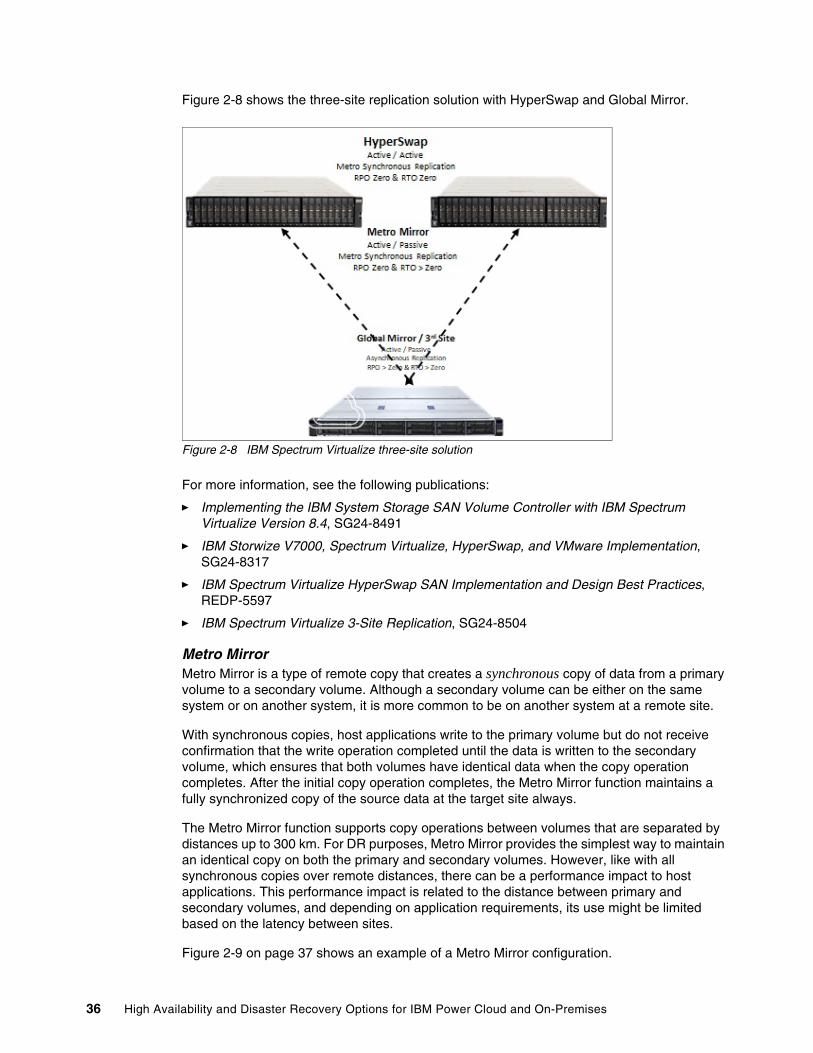
Figure 2-8 shows the three-site replication solution with HyperSwap and Global Mirror.
Figure 2-8 IBM Spectrum Virtualize three-site solution
For more information, see the following publications:
� Implementing the IBM System Storage SAN Volume Controller with IBM Spectrum Virtualize Version 8.4, SG24-8491
� IBM Storwize V7000, Spectrum Virtualize, HyperSwap, and VMware Implementation, SG24-8317
� IBM Spectrum Virtualize HyperSwap SAN Implementation and Design Best Practices, REDP-5597
� IBM Spectrum Virtualize 3-Site Replication, SG24-8504
Metro MirrorMetro Mirror is a type of remote copy that creates a synchronous copy of data from a primary volume to a secondary volume. Although a secondary volume can be either on the same system or on another system, it is more common to be on another system at a remote site.
With synchronous copies, host applications write to the primary volume but do not receive confirmation that the write operation completed until the data is written to the secondary volume, which ensures that both volumes have identical data when the copy operation completes. After the initial copy operation completes, the Metro Mirror function maintains a fully synchronized copy of the source data at the target site always.
The Metro Mirror function supports copy operations between volumes that are separated by distances up to 300 km. For DR purposes, Metro Mirror provides the simplest way to maintain an identical copy on both the primary and secondary volumes. However, like with all synchronous copies over remote distances, there can be a performance impact to host applications. This performance impact is related to the distance between primary and secondary volumes, and depending on application requirements, its use might be limited based on the latency between sites.
Figure 2-9 on page 37 shows an example of a Metro Mirror configuration.
36 High Availability and Disaster Recovery Options for IBM Power Cloud and On-Premises
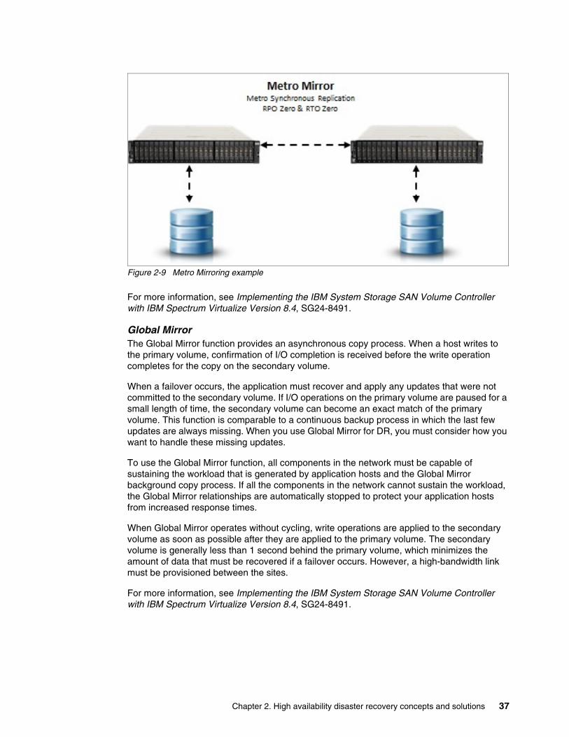
Figure 2-9 Metro Mirroring example
For more information, see Implementing the IBM System Storage SAN Volume Controller with IBM Spectrum Virtualize Version 8.4, SG24-8491.
Global MirrorThe Global Mirror function provides an asynchronous copy process. When a host writes to the primary volume, confirmation of I/O completion is received before the write operation completes for the copy on the secondary volume.
When a failover occurs, the application must recover and apply any updates that were not committed to the secondary volume. If I/O operations on the primary volume are paused for a small length of time, the secondary volume can become an exact match of the primary volume. This function is comparable to a continuous backup process in which the last few updates are always missing. When you use Global Mirror for DR, you must consider how you want to handle these missing updates.
To use the Global Mirror function, all components in the network must be capable of sustaining the workload that is generated by application hosts and the Global Mirror background copy process. If all the components in the network cannot sustain the workload, the Global Mirror relationships are automatically stopped to protect your application hosts from increased response times.
When Global Mirror operates without cycling, write operations are applied to the secondary volume as soon as possible after they are applied to the primary volume. The secondary volume is generally less than 1 second behind the primary volume, which minimizes the amount of data that must be recovered if a failover occurs. However, a high-bandwidth link must be provisioned between the sites.
For more information, see Implementing the IBM System Storage SAN Volume Controller with IBM Spectrum Virtualize Version 8.4, SG24-8491.
Chapter 2. High availability disaster recovery concepts and solutions 37
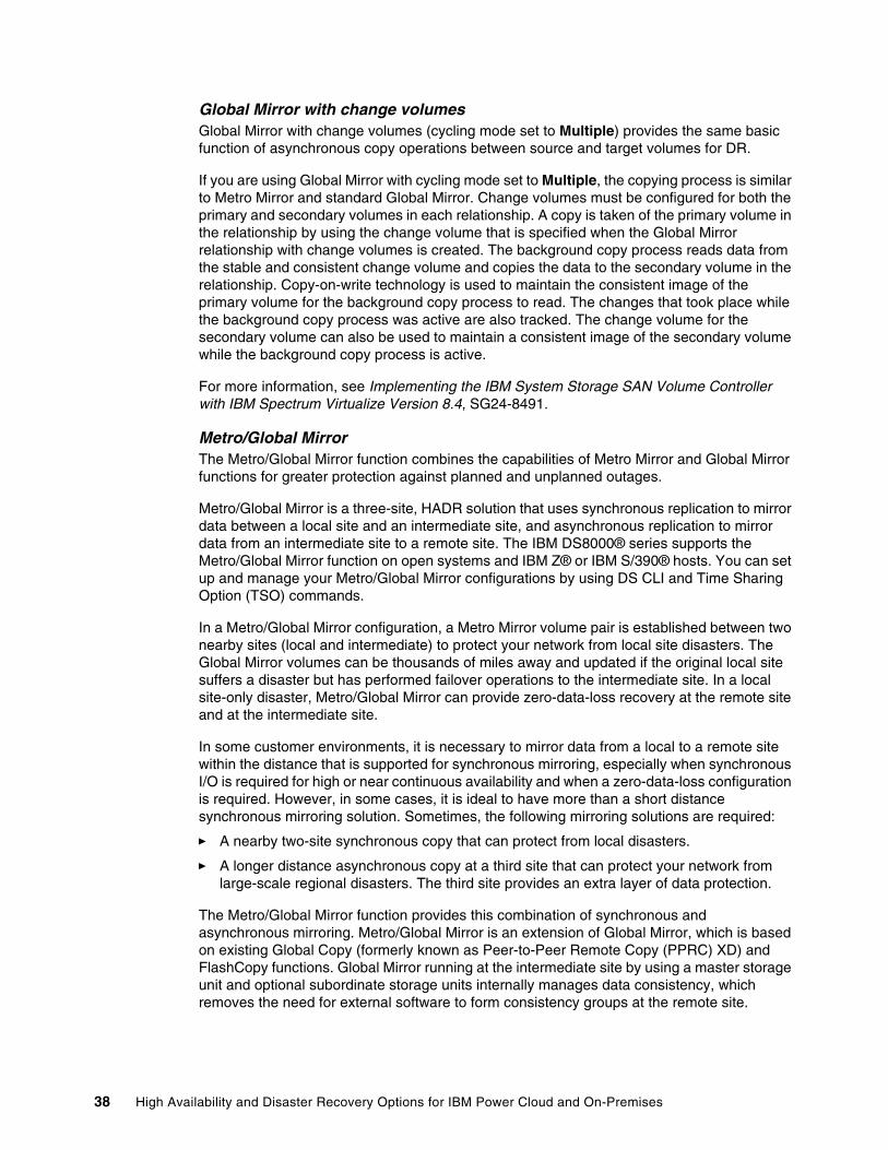
Global Mirror with change volumesGlobal Mirror with change volumes (cycling mode set to Multiple) provides the same basic function of asynchronous copy operations between source and target volumes for DR.
If you are using Global Mirror with cycling mode set to Multiple, the copying process is similar to Metro Mirror and standard Global Mirror. Change volumes must be configured for both the primary and secondary volumes in each relationship. A copy is taken of the primary volume in the relationship by using the change volume that is specified when the Global Mirror relationship with change volumes is created. The background copy process reads data from the stable and consistent change volume and copies the data to the secondary volume in the relationship. Copy-on-write technology is used to maintain the consistent image of the primary volume for the background copy process to read. The changes that took place while the background copy process was active are also tracked. The change volume for the secondary volume can also be used to maintain a consistent image of the secondary volume while the background copy process is active.
For more information, see Implementing the IBM System Storage SAN Volume Controller with IBM Spectrum Virtualize Version 8.4, SG24-8491.
Metro/Global MirrorThe Metro/Global Mirror function combines the capabilities of Metro Mirror and Global Mirror functions for greater protection against planned and unplanned outages.
Metro/Global Mirror is a three-site, HADR solution that uses synchronous replication to mirror data between a local site and an intermediate site, and asynchronous replication to mirror data from an intermediate site to a remote site. The IBM DS8000® series supports the Metro/Global Mirror function on open systems and IBM Z® or IBM S/390® hosts. You can set up and manage your Metro/Global Mirror configurations by using DS CLI and Time Sharing Option (TSO) commands.
In a Metro/Global Mirror configuration, a Metro Mirror volume pair is established between two nearby sites (local and intermediate) to protect your network from local site disasters. The Global Mirror volumes can be thousands of miles away and updated if the original local site suffers a disaster but has performed failover operations to the intermediate site. In a local site-only disaster, Metro/Global Mirror can provide zero-data-loss recovery at the remote site and at the intermediate site.
In some customer environments, it is necessary to mirror data from a local to a remote site within the distance that is supported for synchronous mirroring, especially when synchronous I/O is required for high or near continuous availability and when a zero-data-loss configuration is required. However, in some cases, it is ideal to have more than a short distance synchronous mirroring solution. Sometimes, the following mirroring solutions are required:
� A nearby two-site synchronous copy that can protect from local disasters.
� A longer distance asynchronous copy at a third site that can protect your network from large-scale regional disasters. The third site provides an extra layer of data protection.
The Metro/Global Mirror function provides this combination of synchronous and asynchronous mirroring. Metro/Global Mirror is an extension of Global Mirror, which is based on existing Global Copy (formerly known as Peer-to-Peer Remote Copy (PPRC) XD) and FlashCopy functions. Global Mirror running at the intermediate site by using a master storage unit and optional subordinate storage units internally manages data consistency, which removes the need for external software to form consistency groups at the remote site.
38 High Availability and Disaster Recovery Options for IBM Power Cloud and On-Premises
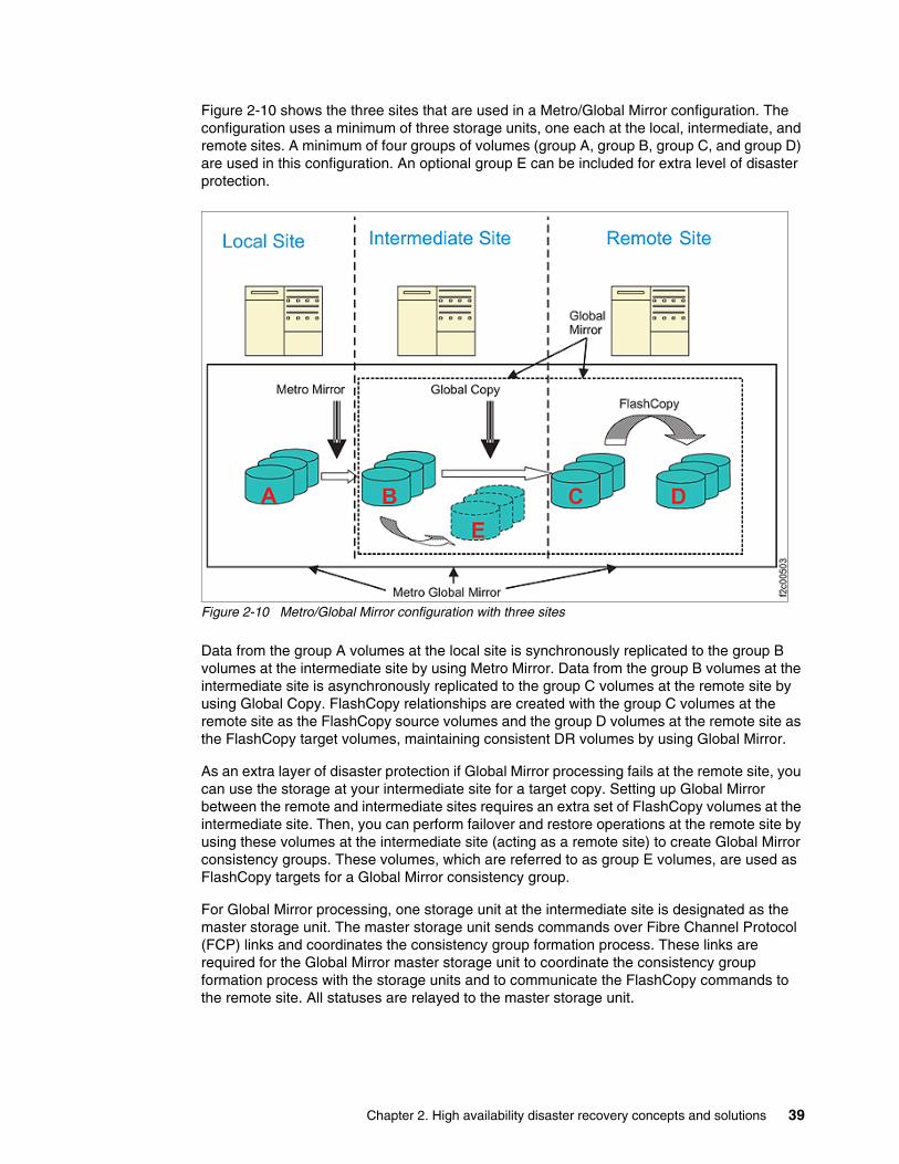
Figure 2-10 shows the three sites that are used in a Metro/Global Mirror configuration. The configuration uses a minimum of three storage units, one each at the local, intermediate, and remote sites. A minimum of four groups of volumes (group A, group B, group C, and group D) are used in this configuration. An optional group E can be included for extra level of disaster protection.
Figure 2-10 Metro/Global Mirror configuration with three sites
Data from the group A volumes at the local site is synchronously replicated to the group B volumes at the intermediate site by using Metro Mirror. Data from the group B volumes at the intermediate site is asynchronously replicated to the group C volumes at the remote site by using Global Copy. FlashCopy relationships are created with the group C volumes at the remote site as the FlashCopy source volumes and the group D volumes at the remote site as the FlashCopy target volumes, maintaining consistent DR volumes by using Global Mirror.
As an extra layer of disaster protection if Global Mirror processing fails at the remote site, you can use the storage at your intermediate site for a target copy. Setting up Global Mirror between the remote and intermediate sites requires an extra set of FlashCopy volumes at the intermediate site. Then, you can perform failover and restore operations at the remote site by using these volumes at the intermediate site (acting as a remote site) to create Global Mirror consistency groups. These volumes, which are referred to as group E volumes, are used as FlashCopy targets for a Global Mirror consistency group.
For Global Mirror processing, one storage unit at the intermediate site is designated as the master storage unit. The master storage unit sends commands over Fibre Channel Protocol (FCP) links and coordinates the consistency group formation process. These links are required for the Global Mirror master storage unit to coordinate the consistency group formation process with the storage units and to communicate the FlashCopy commands to the remote site. All statuses are relayed to the master storage unit.
Chapter 2. High availability disaster recovery concepts and solutions 39
With Incremental Resync, it is possible to change the copy target destination of a copy relationship without requiring a full copy of the data. This function can be used, for example, when an intermediate site fails because of a disaster. In this case, a Global Mirror is established from the local to the remote site, which bypasses the intermediate site. When the intermediate site becomes available again, the Incremental Resync is used to bring it back into the Metro/Global Mirror setup.
For more information, see IBM DS8000 Copy Services: Updated for IBM DS8000 Release 9.1, SG24-8367.
For public cloudDesigned for software-defined storage (SDS) environments, IBM Spectrum Virtualize for Public Cloud represents the solution for public cloud implementations and includes technologies that complement and enhance public cloud offering capabilities.
For example, traditional practices that provide data replication by copying storage at one facility to largely identical storage at another facility are not an option for public cloud. Also, using conventional software to replicate data imposes unnecessary loads on application servers.
IBM Spectrum Virtualize for Public Cloud delivers a powerful solution for the deployment of IBM Spectrum Virtualize software in public clouds, starting with IBM Cloud. This new capability provides a monthly license to deploy and use IBM Spectrum Virtualize in IBM Cloud to enable hybrid cloud solutions, which offer the ability to transfer data between on-premises data centers by using any IBM Spectrum Virtualize-based appliance and IBM Cloud.
With a deployment that is designed for the cloud, IBM Spectrum Virtualize for Public Cloud can be used in any of the over 30 IBM Cloud data centers around the world, where after provisioning the infrastructure an installation script automatically installs the software and creates the cluster.
IBM Spectrum Virtualize for Public Cloud offers a powerful value proposition for enterprise and cloud users who are searching for more flexible and agile ways to deploy block storage on cloud. Using standard Intel servers, IBM Spectrum Virtualize for Public Cloud can be easily added to existing cloud infrastructures to deliver more features and functions, enhancing the storage offering that is available on the public cloud catalog.
The benefits of deploying IBM Spectrum Virtualize on a public cloud platform are two-fold:
� Public cloud storage offering enhancement:
IBM Spectrum Virtualize for Public Cloud enhances the public cloud catalog by increasing standard storage offering capabilities and features improving specific limitations:
– Snapshots: A volume’s snapshots are placed into high-tier storage with no options for lower-end storage. Using IBM Spectrum Virtualize, the administrator has more granular control so that they can provide a snapshot that is stored on lower-end storage for a production volume.
– Volume size: Most cloud storage providers have a maximum volume size (typically a few terabytes), which can be mounted by a few nodes. At the time of writing, IBM Spectrum Virtualize allows for up to 256 TB and up to 20,000 host connections.
– Native storage-based replication: Replication features are natively supported, but are limited to specific data center pairs to a predefined minimum RPO. These features are accessible only when the primary volume is down. IBM Spectrum Virtualize provides greater flexibility in storage replication, which enables user-defined RPO and replication between any other system running IBM Spectrum Virtualize.
40 High Availability and Disaster Recovery Options for IBM Power Cloud and On-Premises
� New features for public cloud storage offering:
IBM Spectrum Virtualize for Public Cloud introduces IBM SVC and IBM Spectrum Virtualize capabilities to the public cloud catalog. These additional features mainly relate to hybrid cloud scenarios and the support to foster these solutions for improved hybrid architectures, which enhance data mobility and management flexibility:
– Replication or migration of data between on-premises storage and public cloud storage.
In a heterogeneous environment (VMware, bare metal, Hyper-V, and others), replication consistency is achieved through storage-based, replica-peering cloud storage with primary storage on-premises. Due to the standardization of the storage service model and the inability to move its own storage to a cloud data center, the storage-based replica is achievable only by involving an SDS solution on-premises.
In this sense, IBM Spectrum Virtualize for Public Cloud offers data replication among the Storwize family, IBM FlashSystem® 7200, IBM FlashSystem 9200, IBM SVC, and IBM VersaStack and Public Cloud, and it extends replication to all types of supported virtualized storage on-premises. Working together, IBM Spectrum Virtualize and IBM Spectrum Virtualize for Public Cloud support synchronous and asynchronous mirroring between the cloud and on-premises for more than 400 different storage systems from many vendors. In addition, these solutions support other services, such as IBM FlashCopy and IBM Easy Tier®.
– DR strategies between on-premises and public cloud data centers as alternative DR solutions. One of the reasons to replicate is to have a copy of the data from which to restart operations in an emergency. IBM Spectrum Virtualize for Public Cloud enables replication for virtual and physical environments, which adds new possibilities compared to software replicators in use today that handle virtual infrastructure only.
– Benefit from familiar, sophisticated storage functions in the cloud to implement reverse mirroring.
IBM Spectrum Virtualize enables the possibility to reverse data replication to offload from a cloud provider back to on-premises or to another cloud provider. IBM Spectrum Virtualize, both on-premises and in the public cloud, provides a data strategy that is independent of the choice of infrastructure. It delivers tightly integrated functions and consistent management across heterogeneous on-premises storage and cloud storage. The software layer that is provided by IBM Spectrum Virtualize on-premises or in the cloud can provide a business advantage by delivering more services faster and more efficiently, enabling real-time business insights and supporting more customer interaction.
Capabilities such as rapid, flexible provisioning, simplified configuration changes, nondisruptive movement of data among tiers of storage, and a single user interface help make the storage infrastructure (and the hybrid cloud) simpler, more cost-effective, and easier to manage.
For more information, see the following resources:
� Implementing IBM Spectrum Virtualize for Public Cloud Version 8.3.1, REDP-5602
� Implementing IBM Spectrum Virtualize for Public Cloud on AWS Version 8.3.1, REDP-5588
� Achieving Hybrid Cloud Cyber Resiliency with IBM Spectrum Virtualize for Public Cloud, REDP-5585
� Multicloud Solution for Business Continuity using IBM Spectrum Virtualize for Public Cloud on AWS Version 1 Release 1, REDP-5545
Chapter 2. High availability disaster recovery concepts and solutions 41
IBM Copy Services ManagerIBM Copy Services Manager (formerly IBM Tivoli Storage Productivity Center for Replication, which is a component of IBM Tivoli Storage Productivity Center and IBM SmartCloud® Virtual Storage Center) manages copy services in IBM storage environments. Copy services are features that are used by storage systems to configure, manage, and monitor data replication functions. These copy services include IBM FlashCopy, Metro Mirror, Global Mirror, and Metro/Global Mirror data replication.
IBM Copy Services Manager automates key replication management tasks to help you improve the efficiency of your storage replication. You can use a simple GUI or CLI to configure, automate, manage, and monitor all important data replication tasks in your environment, including the following tasks:
� Manage and monitor multisite environments to meet DR requirements.
� Automate the administration and configuration of data replication features.
� Keep data on multiple, related volumes consistent across storage systems in a planned or unplanned outage.
� Recover to a remote site to reduce downtime of critical applications.
� Provide HA for applications by using IBM HyperSwap technology.
� Practice recovery processes while DR capabilities are maintained.
� Plan for replication when you are provisioning storage.
� Monitor and track replication operations.
� Automate the mapping of source volumes to target volumes.
Copy Services Manager runs on Windows, AIX, Linux, Linux on IBM Z, and IBM z/OS® OSs. When it is running on z/OS, Copy Services Manager uses the Fibre Channel connection (IBM FICON®) to connect to and manage count-key data (CKD) volumes.
For more information, see the IBM Copy Services base publications at IBM Copy Services Manager documentation.
There is also more information and demonstrations that are available at the IBM Copy Services Manager YouTube Channel.
Geographic Logical Volume ManagerGLVM is an IP address-based replication facility that is both native and exclusive to the AIX OS. The main function of GLVM is mirroring local or production site data across an IP address-based network to a system at a remote or backup site. A total failure of the node at the local site does not cause the loss of data on the node at the remote site. GLVM does not provide any automated fallover to the remote site, but it is a supported component that PowerHA SystemMirror for AIX can use to provide automated recovery. For more information about this combination, see Chapter 7, “Geographical Logical Volume Manager configuration assistant” in IBM PowerHA SystemMirror V7.2.3 for IBM AIX and V7.22 for Linux, SG24-8434.
GLVM is based on the AIX native LVM facility, and it supports up to three total copies. However, typically only one copy is at a remote backup site. To use GLVM, an AIX instance with enough storage for the replication must be online and available at each location and connected by at least one IP network. GLVM keeps data volume groups synchronized and not the base operating system (BOS) volume group, rootvg. GLVM also supports both raw logical volumes and file systems.
42 High Availability and Disaster Recovery Options for IBM Power Cloud and On-Premises
GLVM is storage-type independent. If the storage is supported on AIX with native LVM, then it also can be used with GLVM, which also means that there is no requirement for similar storage types at each location. Internal disks locally can be mirrored across an IP network to either internal or external disks at the remote location. You also can mirror external disks locally to either internal or external disks remotely. Though you can mix storage, there might be performance implications. The key performance factor is that the I/O rates can never be faster than the slowest common denominator, which often is the IP network, but also can be because of old internal disks at either site.
GLVM supports both synchronous and asynchronous forms of replication. When RPO is zero, synchronous is required. When RPO is greater than zero, then asynchronous mode is an option. Although technically there is no distance limitation in using either option, the key factors for determining which method to use are bandwidth, latency, and cache logical volume size. Although it might be wanted to have an RPO of zero with 5000 km between sites, the latency most likely will result in unacceptable performance.
For more information about configuring GLVM, see the following resources:
� Seismic
� Replicating data to the IBM Cloud: GLVM
IBM i geographic mirroring Geographic mirroring is a function of the IBM i OS. All the data that is placed in the production copy of the independent auxiliary storage pool (IASP) is mirrored to a second IASP on a second, remote system. The replication is done within the OS, so this solution can be used with any type of storage that is supported by IBM i. There is both a synchronous and an asynchronous version of geographic mirroring.
The benefits of this solution are essentially the same as the switched LUN solution with the added advantage of providing DR to a second copy at increased distance. The biggest benefit continues to be operational simplicity. The switching operations are essentially the same as the ones of the switched LUN solution, except that you switch to the mirror copy of the IASP, making this solution a straightforward HA one to deploy and operate. As in the switched LUN solution, objects that are not in the IASP must be handled by some other mechanism, such as the administrative domain, and the IASP cannot be brought online to an earlier system. Geographic mirroring also provides real-time replication support for hosted integrated environments, such as Microsoft Windows and Linux. This support is not generally possible through journal-based logical replication.
Because geographic mirroring replication is within the IBM i OS, a potential limitation of a geographic mirroring solution is performance impacts in certain workload environments. For synchronous geographic mirroring, when running I/O-intensive batch jobs, some performance degradation on the primary system is possible. Also, be aware of the increased CPU that is required to support geographic mirroring.
The backup copy of the independent disk pool cannot be accessed while the data synchronization is in process. For example, if you want to back up to tape from the geographically mirrored copy, you must quiesce operations on the source system and detach the mirrored copy. Then, you must vary on the detached copy of the independent disk pool on the backup system, perform the backup procedure, and then reattach the independent disk pool to the original production host. Then, synchronization of the data that was changed while the independent disk pool was detached is performed. Your HA solution is running exposed, which means that there is no up to date second data set while doing the backups and when synchronization is occurring. Geographic mirroring uses source and target side tracking to minimize this exposure.
Chapter 2. High availability disaster recovery concepts and solutions 43
The following list shows the characteristics of geographic mirroring:
� All data that is maintained in the independent disk pool is replicated to a second copy of the data on a second system.
� Replication is a function of the IBM i OS, so any type of storage can be used.
� The application can be switched to the backup system and operate on the independent disk pool copy.
� Two copies of the data eliminate a SPOF.
� When using synchronous geographic mirroring, both copies of the IASP are identical. Synchronous geographic mirroring over a distance might impact application performance due to communication latency.
� A second copy of data can be geographically dispersed if you use asynchronous geographic mirroring. In an unplanned outage on the source system, a few seconds of data loss is possible.
� Data transmission over up to four TCP/IP communication lines for throughput and redundancy.
� As a best practice, use a separate line for the clustering heartbeat because sharing the heartbeat with a data port can cause contention and possible timeouts.
� There are offline saves and queries to a backup copy of the data while a backup data set is detached.
� Data resiliency is not maintained while a backup data set is detached. Data resiliency is resumed after partial or full resynchronization completes.
� Can be used with the IBM i switch LUN technology.
� A system performance impact is associated with running geographic mirroring.
� As a best practice, configure separate main storage pools or user jobs that access independent disk pools to prevent those jobs from contending with other jobs on the system and using more main storage than wanted.
More specifically, independent disk pool jobs should not use the machine pool or base pool. If independent disk pool jobs use the same memory as jobs that are not accessing the independent disk pools, independent disk pool jobs can monopolize the memory pool, lock out other jobs, and in extreme situations deadlock the system. Exposure for this situation is greater when using geographic mirroring.
� Journaled objects in the independent disk pool ensure a data update to target system.
� Simple monitoring of mirror processes.
� There is a cost that is associated with a second set of disks.
� Replication is at a memory-page level that is managed by IBM i.
IBM Spectrum ScaleIBM Spectrum Scale (previously called IBM General Parallel File System (GPFS) is a cluster file system that provides concurrent access to a file system or file systems from multiple nodes. All these nodes can be SAN-attached or a mix of SAN and network-attached, which enables high-performance access to this common set of data to support a scale-out solution or provide a HA platform.
44 High Availability and Disaster Recovery Options for IBM Power Cloud and On-Premises
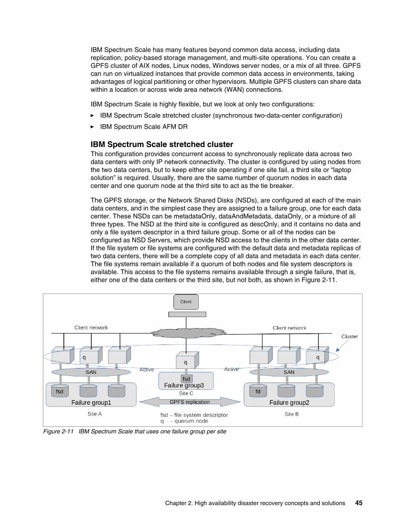
IBM Spectrum Scale has many features beyond common data access, including data replication, policy-based storage management, and multi-site operations. You can create a GPFS cluster of AIX nodes, Linux nodes, Windows server nodes, or a mix of all three. GPFS can run on virtualized instances that provide common data access in environments, taking advantages of logical partitioning or other hypervisors. Multiple GPFS clusters can share data within a location or across wide area network (WAN) connections.
IBM Spectrum Scale is highly flexible, but we look at only two configurations:
� IBM Spectrum Scale stretched cluster (synchronous two-data-center configuration)
� IBM Spectrum Scale AFM DR
IBM Spectrum Scale stretched clusterThis configuration provides concurrent access to synchronously replicate data across two data centers with only IP network connectivity. The cluster is configured by using nodes from the two data centers, but to keep either site operating if one site fail, a third site or “laptop solution” is required. Usually, there are the same number of quorum nodes in each data center and one quorum node at the third site to act as the tie breaker.
The GPFS storage, or the Network Shared Disks (NSDs), are configured at each of the main data centers, and in the simplest case they are assigned to a failure group, one for each data center. These NSDs can be metadataOnly, dataAndMetadata, dataOnly, or a mixture of all three types. The NSD at the third site is configured as descOnly, and it contains no data and only a file system descriptor in a third failure group. Some or all of the nodes can be configured as NSD Servers, which provide NSD access to the clients in the other data center. If the file system or file systems are configured with the default data and metadata replicas of two data centers, there will be a complete copy of all data and metadata in each data center. The file systems remain available if a quorum of both nodes and file system descriptors is available. This access to the file systems remains available through a single failure, that is, either one of the data centers or the third site, but not both, as shown in Figure 2-11.
Figure 2-11 IBM Spectrum Scale that uses one failure group per site
Chapter 2. High availability disaster recovery concepts and solutions 45
IBM Spectrum Scale Active File Management DRAFM is a feature that is available in IBM Spectrum Scale Standard Edition (or higher). It provides a scalable, high-performance file system caching layer that is integrated with the GPFS cluster file system. With AFM, you can create associations from a local GPFS cluster to a remote cluster or storage, and define the location and flow of file data to automate the management of the data. With this setup, you can implement a single namespace view across sites worldwide.
AFM-based asynchronous DR is a fileset-level replication DR capability. This capability is a one-to-one active-passive model and is represented by two sites: primary and secondary.
The primary site is a read/write file set where the applications are running and has read/write access to the data. The secondary site is read-only. All the data from the primary site is asynchronously synchronized with the secondary site. The primary and secondary sites can be independently created in a storage and network configuration. After the sites are created, you can establish a relationship between the two file sets. The primary site is available for the applications even when communication or the secondary site fails. When the connection with the secondary site is restored, the primary site detects the restored connection and asynchronously updates the secondary site.
The following data is replicated from the primary site to the secondary site:
� File-user data.
� Metadata, which includes the user-extended attributes except for the inode number and a time.
� Hard links.
� Renames.
The following file system and file-set-related attributes from the primary site are not replicated to the secondary site:
� User, group, and file set quotas
� Replication factors
� Dependent file sets
AFM DR can be enabled only on GPFS independent file sets. An independent file set that has dependent file sets cannot be converted into an AFM DR file set.
A consistent view of the data in the primary file set can be propagated to the secondary file set by using file-set-based snapshots (psnaps). RPO defines the frequency of these snapshots and can send alerts through events when it cannot achieve the RPO. RPO is disabled by default. The minimum time that you can set as RPO is 720 minutes. AFM-based asynchronous DR can reconfigure the old primary site or establish a new primary site and synchronize it with the current primary site.
Individual files in the AFM DR file sets can be compressed. Compressing files saves disk space. Snapshot data migration is also supported. For more information, see ILM for snapshots in the IBM Spectrum Scale Version 5.1.0 Administration Guide.
When a disaster occurs on the primary site, the secondary site can be failed over to become the primary site. When required, the file sets of the secondary site can be restored to the state of the last consistent RPO snapshot. Applications can be moved or failed over to the acting primary site. This application movement helps to ensure stability with minimal downtime and minimal data loss and makes it possible for applications to be failed back to the primary site as soon as the (new) primary is on the same level as the acting primary.
46 High Availability and Disaster Recovery Options for IBM Power Cloud and On-Premises
ConceptsAFM DR does not offer a feature to check consistency of files across primary and secondary sites. However, you can use any third-party utility to check that consistency after files are replicated.
You can simultaneously configure a site for continuous replication of IBM Spectrum Scale data along with the AFM DR site. With IBM Spectrum Scale continuous replication, you can achieve a near DR and a far DR with an AFM DR site.
AFM DR uses the same underlying infrastructure as AFM. AFM DR is characterized by two modes: the file set in the primary cluster uses the primary mode, and the file set in the secondary cluster uses the secondary mode.
AFM DR is supported over both NFS v3 and GPFS protocol. The primary file set is owned by the primary gateway, which communicates with the NFS server on the secondary side. The primary to secondary relationship is strictly one-to-one.
AFM revalidation does not apply to primary file sets. All files are always cached because the primary is the only writer and the secondary is in read-only mode.
You can convert the single writer (SW) or independent writer (IW) relationship to a DR relationship. However, you cannot convert a DR relationship to an SW or IW relationship.
FeaturesThe following AFM features are offered on AFM DR file sets:
� Force the flushing of contents before an async delay occurs.
� Parallel data transfers.
� Peer snapshot (psnap).
� Gateway node failure and recovery.
� Operation with a disconnected secondary.
� Using IBM Spectrum Protect for space management (Hierarchical Storage Management (HSM)).
� Disabling AFM DR.
� Using AFM DR with encryption.
� Stop and start replication on a file set.
You can use mmbackup command to back up all files from the primary because all files are in a cached state on the primary file set. Like AFM file sets, IBM Spectrum Protect (HSM) can be connected to a primary, secondary, or both sides. When HSM is connected to the primary side, set AFMSKIPUNCACHEDFILES yes in the dsm.sys file. AFM features such as revalidation, eviction, prefetch, partial file caching, expiration, resynchronization, failover, and showing home snapshots are not offered on AFM DR file sets.
Chapter 2. High availability disaster recovery concepts and solutions 47
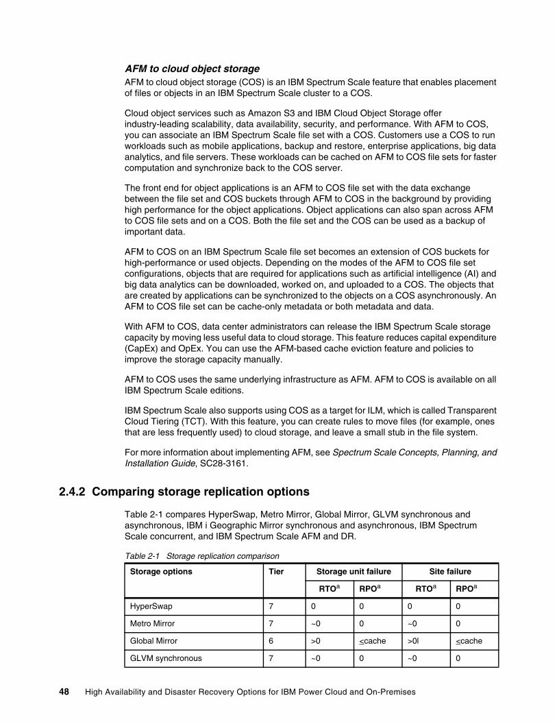
AFM to cloud object storageAFM to cloud object storage (COS) is an IBM Spectrum Scale feature that enables placement of files or objects in an IBM Spectrum Scale cluster to a COS.
Cloud object services such as Amazon S3 and IBM Cloud Object Storage offer industry-leading scalability, data availability, security, and performance. With AFM to COS, you can associate an IBM Spectrum Scale file set with a COS. Customers use a COS to run workloads such as mobile applications, backup and restore, enterprise applications, big data analytics, and file servers. These workloads can be cached on AFM to COS file sets for faster computation and synchronize back to the COS server.
The front end for object applications is an AFM to COS file set with the data exchange between the file set and COS buckets through AFM to COS in the background by providing high performance for the object applications. Object applications can also span across AFM to COS file sets and on a COS. Both the file set and the COS can be used as a backup of important data.
AFM to COS on an IBM Spectrum Scale file set becomes an extension of COS buckets for high-performance or used objects. Depending on the modes of the AFM to COS file set configurations, objects that are required for applications such as artificial intelligence (AI) and big data analytics can be downloaded, worked on, and uploaded to a COS. The objects that are created by applications can be synchronized to the objects on a COS asynchronously. An AFM to COS file set can be cache-only metadata or both metadata and data.
With AFM to COS, data center administrators can release the IBM Spectrum Scale storage capacity by moving less useful data to cloud storage. This feature reduces capital expenditure (CapEx) and OpEx. You can use the AFM-based cache eviction feature and policies to improve the storage capacity manually.
AFM to COS uses the same underlying infrastructure as AFM. AFM to COS is available on all IBM Spectrum Scale editions.
IBM Spectrum Scale also supports using COS as a target for ILM, which is called Transparent Cloud Tiering (TCT). With this feature, you can create rules to move files (for example, ones that are less frequently used) to cloud storage, and leave a small stub in the file system.
For more information about implementing AFM, see Spectrum Scale Concepts, Planning, and Installation Guide, SC28-3161.
2.4.2 Comparing storage replication options
Table 2-1 compares HyperSwap, Metro Mirror, Global Mirror, GLVM synchronous and asynchronous, IBM i Geographic Mirror synchronous and asynchronous, IBM Spectrum Scale concurrent, and IBM Spectrum Scale AFM and DR.
Table 2-1 Storage replication comparison
Storage options Tier Storage unit failure Site failure
RTOa RPOa RTOa RPOa
HyperSwap 7 0 0 0 0
Metro Mirror 7 ~0 0 ~0 0
Global Mirror 6 >0 <cache >0l <cache
GLVM synchronous 7 ~0 0 ~0 0
48 High Availability and Disaster Recovery Options for IBM Power Cloud and On-Premises
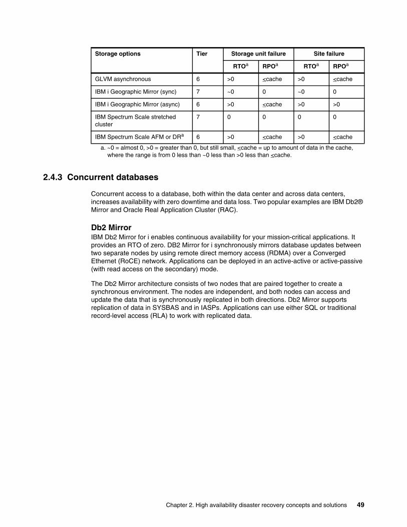
2.4.3 Concurrent databases
Concurrent access to a database, both within the data center and across data centers, increases availability with zero downtime and data loss. Two popular examples are IBM Db2® Mirror and Oracle Real Application Cluster (RAC).
Db2 MirrorIBM Db2 Mirror for i enables continuous availability for your mission-critical applications. It provides an RTO of zero. DB2 Mirror for i synchronously mirrors database updates between two separate nodes by using remote direct memory access (RDMA) over a Converged Ethernet (RoCE) network. Applications can be deployed in an active-active or active-passive (with read access on the secondary) mode.
The Db2 Mirror architecture consists of two nodes that are paired together to create a synchronous environment. The nodes are independent, and both nodes can access and update the data that is synchronously replicated in both directions. Db2 Mirror supports replication of data in SYSBAS and in IASPs. Applications can use either SQL or traditional record-level access (RLA) to work with replicated data.
GLVM asynchronous 6 >0 <cache >0 <cache
IBM i Geographic Mirror (sync) 7 ~0 0 ~0 0
IBM i Geographic Mirror (async) 6 >0 <cache >0 >0
IBM Spectrum Scale stretched cluster
7 0 0 0 0
IBM Spectrum Scale AFM or DRa 6 >0 <cache >0 <cache
a. ~0 = almost 0, >0 = greater than 0, but still small, <cache = up to amount of data in the cache, where the range is from 0 less than ~0 less than >0 less than <cache.
Storage options Tier Storage unit failure Site failure
RTOa RPOa RTOa RPOa
Chapter 2. High availability disaster recovery concepts and solutions 49
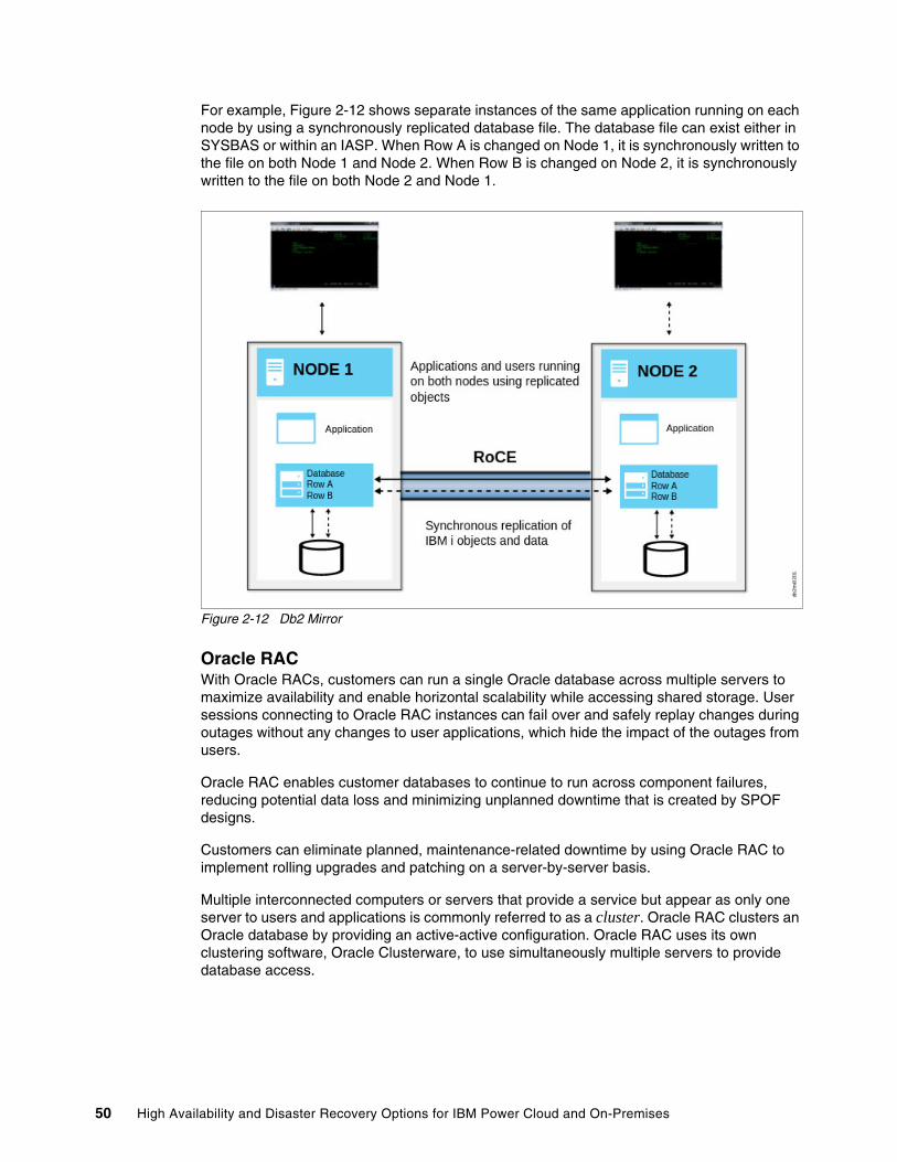
For example, Figure 2-12 shows separate instances of the same application running on each node by using a synchronously replicated database file. The database file can exist either in SYSBAS or within an IASP. When Row A is changed on Node 1, it is synchronously written to the file on both Node 1 and Node 2. When Row B is changed on Node 2, it is synchronously written to the file on both Node 2 and Node 1.
Figure 2-12 Db2 Mirror
Oracle RACWith Oracle RACs, customers can run a single Oracle database across multiple servers to maximize availability and enable horizontal scalability while accessing shared storage. User sessions connecting to Oracle RAC instances can fail over and safely replay changes during outages without any changes to user applications, which hide the impact of the outages from users.
Oracle RAC enables customer databases to continue to run across component failures, reducing potential data loss and minimizing unplanned downtime that is created by SPOF designs.
Customers can eliminate planned, maintenance-related downtime by using Oracle RAC to implement rolling upgrades and patching on a server-by-server basis.
Multiple interconnected computers or servers that provide a service but appear as only one server to users and applications is commonly referred to as a cluster. Oracle RAC clusters an Oracle database by providing an active-active configuration. Oracle RAC uses its own clustering software, Oracle Clusterware, to use simultaneously multiple servers to provide database access.
50 High Availability and Disaster Recovery Options for IBM Power Cloud and On-Premises
Oracle Clusterware is a portable cluster management solution that is integrated with Oracle Database. Oracle Clusterware is also a required component for using Oracle RAC. In addition, Oracle Clusterware enables both non-cluster Oracle databases and Oracle RAC databases to use the Oracle HA infrastructure. With Oracle Clusterware, you can create a clustered pool of storage to be used by any combination of non-cluster and Oracle RAC databases.
Oracle Clusterware is the only clusterware that you need for most platforms on which Oracle RAC operates. You also can use clusterware from other vendors if the clusterware is certified for Oracle RAC.
IBM and Oracle have had a longtime agreement that resulted in the IBM Oracle International Competency Center (ICC). This collaboration resulted in providing premier solutions and documentation of these solutions.
For more information about implementing Oracle RAC on IBM Power, see the following resources:
� IBM Spectrum Scale and Oracle Database 12cR2 RAC on IBM Power Systems
� Oracle Database 19c and Oracle Database 19c RAC on IBM: Tips and Considerations
� Oracle Real Application Clusters on IBM AIX: Best practices in memory tuning and configuring for system stability
� Oracle 19c to 12c and 11.2.0.4 Database Performance Considerations with AIX on Power Systems including IBM POWER9
You also can send an email to [email protected].
2.4.4 Application-based and log shipping
Many enterprise-level applications today provide their own inherent HADR capabilities. The following sections describe only some of the current offerings.
Db2IBM Db2 server contains functions that support many HA strategies:
� Automatic client reroute (ACR) roadmap
ACR is an IBM Db2 server feature that redirects client applications from a failed server to an alternative server so that the applications can continue their work with minimal interruption. ACR can be accomplished only if an alternative server was specified before the failure.
� Server lists
The server list is used by IBM Data Server drivers and clients for workload balancing (WLB) and ACR operation. The server list contains a list of addresses and the relative priority of those addresses. When a client connects to a Db2 server over TCP/IP, the server list is returned to and cached by the client. The server periodically provides a refreshed server list to the client.
� Db2 fault monitor facilities for Linux and UNIX
Available on UNIX based systems only, Db2 fault monitor facilities keep IBM Db2 server databases running by monitoring Db2 database manager instances and restarting any instance that exits prematurely.
Chapter 2. High availability disaster recovery concepts and solutions 51
� HADR
HADR provides a HA solution for both partial and complete site failures. HADR protects against data loss by replicating data changes from a source database that is called the primary database to the target databases, which are called the standby databases. HADR supports up to three remote standby servers.
� Db2 High Availability Feature
The Db2 High Availability Feature enables integration between a Db2 server and cluster-managing software.
� HA through log shipping
Log shipping is the process of copying whole log files to a standby machine either from an archive device or through a user exit program that is running against the primary database. A scheduled job on the standby issues the ROLLFORWARD DATABASE command at a specified interval to keep the standby current in terms of log replay.
� Log mirroring
IBM Db2 server supports log mirroring at the database level. Mirroring log files helps protect a database from accidental deletion of an active log and data corruption that is caused by hardware failure.
� HA through suspended I/O and online split mirror support
Db2 server suspended I/O support enables you to split mirrored copies of your primary database without taking the database offline. You can use this feature to quickly create a standby database to take over if the primary database fails.
HADR Data FlowEach rectangle in Figure 2-13 on page 53 represents a thread (also known as an Engine Dispatchable Unit (EDU)) in the Db2 engine. Here are the threads that are relevant to HADR:
� db2agent: A thread that serves an SQL client connection. There are multiple threads per database.
� db2loggw: A thread that writes log records to log files. There is one per database.
� db2hadrp: The HADR primary side EDU. There is one per database.
� db2hadrs: The HADR standby side EDU. There is one per database.
� db2lfr: The Log File Reader (LFR) thread. There is one per database.
� db2shred: The Shredder EDU. Shreds log pages into log records. There is one per database.
� db2redom: The Redo (replay) master thread. There is one per database.
� db2redow: The Redo (replay) worker thread. There are multiple threads per database.
52 High Availability and Disaster Recovery Options for IBM Power Cloud and On-Premises
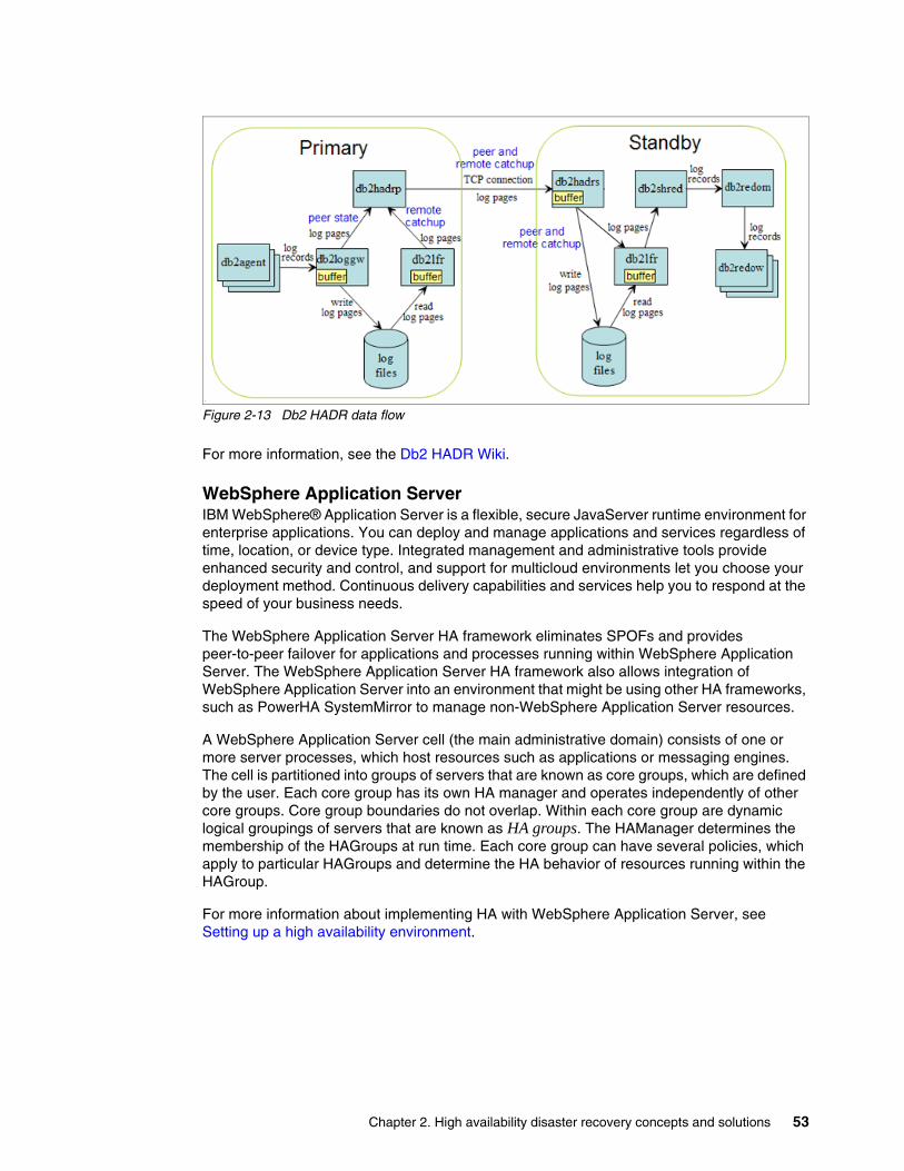
Figure 2-13 Db2 HADR data flow
For more information, see the Db2 HADR Wiki.
WebSphere Application ServerIBM WebSphere® Application Server is a flexible, secure JavaServer runtime environment for enterprise applications. You can deploy and manage applications and services regardless of time, location, or device type. Integrated management and administrative tools provide enhanced security and control, and support for multicloud environments let you choose your deployment method. Continuous delivery capabilities and services help you to respond at the speed of your business needs.
The WebSphere Application Server HA framework eliminates SPOFs and provides peer-to-peer failover for applications and processes running within WebSphere Application Server. The WebSphere Application Server HA framework also allows integration of WebSphere Application Server into an environment that might be using other HA frameworks, such as PowerHA SystemMirror to manage non-WebSphere Application Server resources.
A WebSphere Application Server cell (the main administrative domain) consists of one or more server processes, which host resources such as applications or messaging engines. The cell is partitioned into groups of servers that are known as core groups, which are defined by the user. Each core group has its own HA manager and operates independently of other core groups. Core group boundaries do not overlap. Within each core group are dynamic logical groupings of servers that are known as HA groups. The HAManager determines the membership of the HAGroups at run time. Each core group can have several policies, which apply to particular HAGroups and determine the HA behavior of resources running within the HAGroup.
For more information about implementing HA with WebSphere Application Server, see Setting up a high availability environment.
Chapter 2. High availability disaster recovery concepts and solutions 53
IBM MQIBM MQ, formerly known as IBM MQSeries® and IBM WebSphere MQ, enables applications to communicate at different times and in many diverse computing environments. IBM MQ supports the exchange of information between applications, systems, services, and files by sending and receiving message data by using messaging queues. This approach simplifies the creation and maintenance of business applications. IBM MQ works with a broad range of computing platforms, and it can be deployed across a range of different environments, including on-premises, cloud, and hybrid cloud deployments. IBM MQ supports several different APIs, including Message Queue Interface (MQI), Java Message Service (JMS), REST, .NET, IBM MQ Light, and MQTT.
IBM MQ provides the following features:
� Versatile messaging integration from mainframe to mobile that provides a single, robust messaging backbone for dynamic heterogeneous environments.
� Message delivery with security-rich features that produce auditable results.
� Qualities of service that provide once-only delivery of messages to ensure that messages withstand application and system outages.
� High-performance message transport to deliver data with improved speed and reliability.
� HA and scalable architectures to support an application’s needs.
� Administrative features that simplify messaging management and reduce the time that is spent using complex tools.
� Open standards development tools that support extensibility and business growth.
IBM MQ provides a universal messaging backbone with robust connectivity for flexible and reliable messaging for applications and the integration of existing IT assets by using a service-oriented architecture (SOA).
IBM MQ sends and receives data between your applications, and over networks.
Message delivery is ensured and decoupled from the application: Ensured because IBM MQ exchanges messages transactionally, and decoupled because applications do not have to check that the messages they sent are delivered safely.
� You can secure message delivery between queue managers with TLS.
� With Advanced Message Security (AMS), you can encrypt and sign messages that are put by one application and retrieved by another one.
� Application programmers do not need to have communications programming knowledge.
An IBM MQ messaging system is composed of one or more queue managers. Queue managers are where messaging resources, such as queues, are configured, and what applications connect to, either running on the same system as the queue manager or over the network.
A network of connected queue managers supports asynchronous routing of messages between systems, where producing and consuming applications are connected to different queue managers.
IBM MQ can be managed by using various tools, from the IBM MQ Explorer GUI to scripted or interactive CLI tools or programmatically.
The applications that connect to IBM MQ can be written in any one of many different programming languages and many different APIs, such as C, Cobol, Java, .NET, NodeJS, and Ruby.
54 High Availability and Disaster Recovery Options for IBM Power Cloud and On-Premises
If you want to operate your IBM MQ queue managers in a HA configuration, you can set up your queue managers to work either with a HA manager, such as PowerHA SystemMirror for AIX (formerly High Availability Cluster Multi-Processing (HACMP)), or with IBM MQ multi-instance queue managers. On Linux systems, you can also deploy replicated data queue managers (RDQMs), which use a quorum-based group to provide HA.
Oracle Data GuardOracle Data Guard provides a solution for HA, enhanced performance, and automated failover. You can use Oracle Data Guard to create and maintain multiple standby databases for a primary database. The standby databases can be started in the read-only mode to support reporting users and then returned to the standby mode. Changes to the primary database can be relayed automatically from the primary database to the standby databases with a guarantee of no data lost in the process. The standby database servers can be physically separate from the primary server.
In a Data Guard implementation, a database running in archive log mode is designated as the primary database for an application. One or more standby databases, which are accessible through Oracle Net Services, provide for failover capabilities. Data Guard automatically transmits redo information to the standby databases over an IP network, where it is applied. As a result, the standby database is transactionally consistent.
Depending on how you configure the redo application process, the standby databases might be in sync with the primary database or might lag behind it. The redo log data is transferred to the standby databases through log transport services, as defined through your initialization parameter settings. Log Apply Services apply the redo information to the standby databases.
In a network outage, Data Guard can automatically synchronize the data by applying the redo data to the standby database that was archived at the primary database during the outage period. Data Guard ensures that the data is logically and physically consistent before it is applied to a standby database.
A standby database is a transactionally consistent copy of an Oracle production database that is initially created from a backup copy of the primary database. After the standby database is created and configured, Oracle Data Guard automatically maintains the standby database by transmitting primary database redo data to the standby system, where the redo data is applied to the standby database.
The following types of standby databases are available from Oracle database version 11g onwards:
� Physical
� Logical
� Snapshot
Physical standby databaseA physical standby database3 is an exact, block-for-block copy of a primary database. A physical standby database is maintained as an exact copy by using a process that is called Redo Apply, in which redo data that is received from a primary database is continuously applied to a physical standby database by using the database recovery mechanisms.
3 https://docs.oracle.com/database/121/SBYDB/standby.htm#SBYDB00110>
Chapter 2. High availability disaster recovery concepts and solutions 55
A physical standby database can be opened for read-only access and used to offload queries from a primary database. If a license for the Oracle Active Data Guard option was purchased, Redo Apply can be active while the physical standby database is open, thus allowing queries to return results that are identical to what is returned from the primary database. This capability is known as the real-time query feature.
A physical standby database provides the following benefits:
� HADR
A physical standby database is a robust and efficient HADR solution. Easy-to-manage switchover and failover capabilities allow easy role reversals between the primary and physical standby databases, minimizing the downtime of the primary database for planned and unplanned outages.
� Data protection
A physical standby database can prevent data loss, even in the face of unforeseen disasters. It also supports all data types, and all Data Definition Language (DDL) and Data Manipulation Language (DML) operations that the primary database can support. It also provides a safeguard against data corruption and user errors. Storage-level physical corruption on the primary database is not propagated to a standby database. Similarly, logical corruption or user errors that otherwise cause data loss can be easily resolved.
� Reduction in primary database workload
Oracle Recovery Manager (RMAN) can use a physical standby database to offload backups from a primary database, saving valuable CPU and I/O cycles.
A physical standby database can also be queried while Redo Apply is active, which allows queries to be offloaded from the primary to a physical standby, further reducing the primary workload.
� Performance
The Redo Apply technology that is used by a physical standby database is the most efficient mechanism for keeping a standby database updated with changes being made at a primary database because it applies changes by using low-level recovery mechanisms that bypass all SQL level code layers.
Logical standby databaseA logical standby database is initially created as an identical copy of the primary database, but it later can be altered to have a different structure. The logical standby database is updated by running SQL statements. The flexibility of a logical standby database lets you upgrade Oracle Database software (patch sets and new Oracle Database releases) and perform other database maintenance in rolling fashion with almost no downtime. From Oracle Database 11g onward, the transient logical database-rolling upgrade process also can be used with existing physical standby databases.
Oracle Data Guard automatically applies information from the archived redo log file or standby redo log file to the logical standby database by transforming the data in the log files into SQL statements and then running the SQL statements on the logical standby database. Because the logical standby database is updated by using SQL statements, it must remain open. Although the logical standby database is opened in read/write mode, its target tables for the regenerated SQL are available only for read-only operations. Although those tables are being updated, they can be used simultaneously for other tasks such as reporting, summations, and queries.
56 High Availability and Disaster Recovery Options for IBM Power Cloud and On-Premises
A logical standby database is ideal for HA while still offering DR benefits. Compared to a physical standby database, a logical standby database provides more HA benefits:
� Minimizing downtime on software upgrades.
A logical standby database is ideal for upgrading an Oracle Data Guard configuration in a rolling fashion. Logical standby can be used to greatly reduce the downtime that is associated with applying patch sets and new software releases. A logical standby can be upgraded to the new release and then switched over to become the active primary. This action allows full availability while the old primary is converted to a logical standby and the patch set is applied. Logical standbys provide the underlying platform for the DBMS_ROLLING PL/SQL package, which is available as of Oracle Database 12c Release 1 (12.1). The DBMS_ROLLING package provides functions that allow you to make your Oracle Data Guard configuration HA in the context of rolling upgrades and other storage reorganization.
� Support for reporting and decision support requirements.
A key benefit of logical standby is that auxiliary structures can be created to optimize the reporting workload, that is, structures that might have a prohibitive impact on the primary's transactional response time. A logical standby can have its data physically reorganized into a different storage type with different partitioning; have many different indexes; have on-demand refresh materialized views that are created and maintained; and can be used to drive the creation of data cubes and other online analytical processing (OLAP) data views. However, a logical standby database does not allow for any transformation of your data (such as replicating only a subset of columns or allowing extra columns on user tables). For those types of reporting activities, Oracle GoldenGate is the Oracle preferred solution.
Snapshot standby databaseA snapshot standby database is a type of updatable standby database that provides full data protection for a primary database. A snapshot standby database receives and archives, but does not apply, redo data from its primary database. Redo data that is received from the primary database is applied when a snapshot standby database is converted back into a physical standby database after discarding all local updates to the snapshot standby database.
A snapshot standby database diverges from its primary database over time because redo data from the primary database is not applied as it is received. Local updates to the snapshot standby database cause more divergence. The data in the primary database is fully protected because a snapshot standby can be converted back into a physical standby database at any time, and then the redo data that is received from the primary is applied.
A snapshot standby database is a fully updatable standby database that provides DR and data protection benefits that are like the ones for a physical standby database. Snapshot standby databases are best used in scenarios where the benefit of having a temporary, updatable snapshot of the primary database justifies the increased time to recover from primary database failures.
The benefits of using a snapshot standby database include the following ones:
� It provides an exact replica of a production database for development and testing purposes while maintaining data protection always. You can use the Oracle Real Application Testing option to capture the primary database workload and then replay it for test purposes on the snapshot standby.
� It can be easily refreshed to contain current production data by converting to a physical standby and resynchronizing.
Chapter 2. High availability disaster recovery concepts and solutions 57
Creating a snapshot standby, testing, resynchronizing with production, and then creating a snapshot standby and test again is a cycle that can be repeated as often as needed. The same process can be used to easily create and regularly update a snapshot standby for reporting purposes where read/write access to data is required.
For more information about best practices for HA and maximum availability for Oracle, see Oracle Maximum Availability Architecture.
Oracle GoldenGateOracle GoldenGate4 is a licensed software product that can replicate, filter, and transform data between databases. Oracle GoldenGate replicates data between Oracle databases to other supported heterogeneous database and between heterogeneous databases. Also, data to Java Messaging Queues, Flat Files, and Big Data targets in combination with Oracle GoldenGate for Big Data can be replicated. Although the software has many uses, it often is used for data migrations and HADR to help achieve business continuity.
For more information about GoldenGate, see Oracle GoldenGate.
SAP HANASAP HANA is inherently designed for HA. It can recover from most hardware faults, errors, and entire system or data center failures. Like many enterprise-class applications, HANA provides three main levels DR support:
� Backups
The SAP HANA database is in-memory for performance, and it uses persistent storage to survive server outages without loss of data. Two types of persistent storage are used:
– Transaction redo logs
Changes are recorded so that after an outage the most recent consistent state of the database can be restored. This task is achieved by replaying the changes that are recorded in the log, redoing the completed changes, and rolling back the incomplete ones.
– Savepoints for data changes
A savepoint is a consistent point in time across all SAP HANA processes when all data is written to storage. One goal is to reduce the time to recover from an outage because the logs need to be replayed only from the latest savepoint.
Normally, savepoints overwrite previous savepoints, but they can be preserved for future use, which is equivalent to a snapshot that can be used to roll back to a specific point in time.
Shipping both the savepoints and transaction redo logs allow recovery of the SAP HANA database after a disaster, and depending on the technology that is used, recovery time can range from hours to days.
� System replication
In general, there is a single HANA instance at the primary site and another one at the secondary site. Each site has their own independent storage areas for the HANA data, log, and shared areas. In this DR scenario, the DR site has a fully duplicated environment to protect your data from a total loss of the primary site. So, each HANA system has its own IP address, and each site has its own SAP application infrastructure pointing to that site’s HANA DB IP address.
4 https://docs.oracle.com/goldengate/c1230/gg-winux/GGCON/introduction-oracle-goldengate.htm#GGCON-GUID-EF513E68-4237-4CB3-98B3-2E203A68CBD4
58 High Availability and Disaster Recovery Options for IBM Power Cloud and On-Premises
The system replication technology within SAP HANA creates unidirectional replication for the contents of the data and log areas. The primary site replicates data and logs to the secondary site, but not vice versa. The secondary system has a replication receiver status (secondary system), and it can be set up for read-only DB access so that it is not idle.
If there is a failure in the primary site, all you need to do is perform a takeover operation on the secondary node. This operation is a DB operation that is performed by the basis team and informs the secondary node to come online with its full range of capabilities and operate as a normal as an independent instance. The replication relationship with the primary site is broken. When the failed node comes back online, it is outdated in terms of DB content, but all you need to do is create the replication in the reverse order from the secondary site to the primary site. After your sites are synchronized again, you can choose to perform another takeover operation to move the DB back to its original primary site.
� Storage replication
A problem with backups is the loss of data between the time of failure and the last backup. A best practice is to replicate all data. Many storage vendors offer storage-based replication solutions. There are some certified SAP vendor-specific solutions that provide synchronous replication, which means that the transaction is marked completed only when the locally persisted transaction log is replicated remotely. Synchronous storage replication technically has no distance limitation, but often it is 100 km or less to keep round-trip latency to a minimum and acceptable level.
High availability for SAP HANASAP HANA is designed for HA and supports recovering from hardware and software errors. HA is achieved by eliminating SPOFs and rapidly resuming operations with minimum business loss after a system outage. SAP HANA also supports a DR configuration with multiple data centers.
Because SAP HANA is an in-memory database, it can manage both the integrity of data in memory in a failure and load it back as quickly as possible after the failure.
SAP HANA uses the following components for HA:
� A watchdog to automatically restart any stopped services.
� The ability to fail over from a failed host to a standby host.
� System replication.
This process replicates the in-memory databases from the primary system to a secondary system. This configuration offers several solutions:
– HA with pre-installation for faster recovery.
– DR with replication to another site.
– Load sharing with reporting running against the secondary system.
System replication supports database replication at the system level or at the tenant databases level.
SAP HANA supports the following items for DR:
� Off-site storage of backups
� Storage replication to a remote data center (synchronous or asynchronous)
� System replication
� Virtual persistent memory (VPMEM)
Chapter 2. High availability disaster recovery concepts and solutions 59
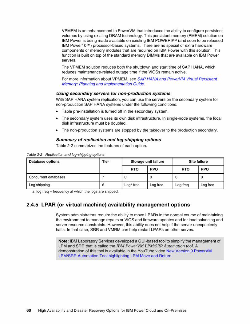
VPMEM is an enhancement to PowerVM that introduces the ability to configure persistent volumes by using existing DRAM technology. This persistent memory (PMEM) solution on IBM Power is being made available on existing IBM POWER9™ (and soon to be released IBM Power10™) processor-based systems. There are no special or extra hardware components or memory modules that are required on IBM Power with this solution. This function is built on top of the standard memory DIMMs that are available on IBM Power servers.
The VPMEM solution reduces both the shutdown and start time of SAP HANA, which reduces maintenance-related outage time if the VIOSs remain active.
For more information about VPMEM, see SAP HANA and PowerVM Virtual Persistent Memory: Planning and Implementation Guide.
Using secondary servers for non-production systemsWith SAP HANA system replication, you can use the servers on the secondary system for non-production SAP HANA systems under the following conditions:
� Table pre-installation is turned off in the secondary system.
� The secondary system uses its own disk infrastructure. In single-node systems, the local disk infrastructure must be doubled.
� The non-production systems are stopped by the takeover to the production secondary.
Summary of replication and log-shipping optionsTable 2-2 summarizes the features of each option.
Table 2-2 Replication and log-shipping options
2.4.5 LPAR (or virtual machine) availability management options
System administrators require the ability to move LPARs in the normal course of maintaining the environment to manage repairs or VIOS and firmware updates and for load balancing and server resource constraints. However, this ability does not help if the server unexpectedly halts. In that case, SRR and VMRM can help restart LPARs on other serves.
Database options Tier Storage unit failure Site failure
RTO RPO RTO RPO
Concurrent databases 7 0 0 0 0
Log shipping 6 Loga freq
a. log freq = frequency at which the logs are shipped.
Log freq Log freq Log freq
Note: IBM Laboratory Services developed a GUI-based tool to simplify the management of LPM and SRR that is called the IBM PowerVM LPM/SRR Automation tool. A demonstration of this tool is available in the YouTube video New Version 9 PowerVM LPM/SRR Automation Tool highlighting LPM Move and Return.
60 High Availability and Disaster Recovery Options for IBM Power Cloud and On-Premises
Live Partition MobilityLPM is a component of the PowerVM Enterprise Edition hardware feature that moves AIX, IBM i, and Linux LPARs from one system to another one. The mobility process transfers the system environment, which includes the processor state, memory, attached virtual devices, and connected users. All OS types (AIX, IBM i, and Linux) on IBM Power can use LPM. However, a VIOS LPAR cannot use LPM because the VIOS LPAR has dedicated adapter resources. The single biggest key requirement for an LPAR to use LPM is that its adapter devices must all be virtualized.
There are two primary mobility methods:
� Active partition mobility moves LPARs that are running, including the OS and applications, from one system to another one. The LPAR and the applications running on that migrated LPAR do not need to be shut down.
� Inactive/Static partition mobility moves a powered-off AIX, IBM i, or Linux LPAR from one system to another one.
Partition mobility provides systems management flexibility and can be used to improve system availability. For example:
� Planned outages for hardware or firmware maintenance can be avoided by migrating LPARs to another server and then performing the maintenance. Partition mobility can help because you can use it to work around scheduled maintenance activities.
� Outages for server hardware upgrades can be mitigated by migrating LPARs to another server and then performing the upgrade so that work can continue without disruption.
� In a predictive server, LPARs can be migrated to another server before the failure occurs. Partition mobility can help avoid unplanned downtime.
� Consolidating workloads running on several small, underutilized servers onto a single large server.
� WLB from server to server to optimize resource use and workload performance within your computing environment. With active partition mobility, you can manage workloads with minimal, if any, downtime.
� On some IBM Power servers, applications be moved from one server to an upgraded server by using IBM PowerVM Editions LPM or the AIX Live Application Mobility software without affecting availability of the applications.
Although partition mobility provides many benefits, it does not provide the following functions:
� Automatic WLB.
� A bridge to new functions. LPARs must be restarted and possibly reinstalled to take advantage of new features.
� HA.
During an LPM event, a matching profile or clone partition is automatically created on the target server. The partition’s memory is asynchronously copied from the source system to the target server. Any changed memory pages from the partition (“dirty” pages) are recopied at the end. After a threshold is reached that indicates that enough memory pages were successfully copied to the target server, the LPAR on that target server becomes active, and any remaining memory pages are copied synchronously. Then, the original LPAR is automatically deleted from the source server.
Chapter 2. High availability disaster recovery concepts and solutions 61
An inactive LPAR that has never been activated cannot be migrated because the HMC always migrates the last activated profile. In this case, to use inactive partition mobility, you can either select the partition state that is defined in the hypervisor or select the configuration data that is defined in the last activated profile on the source server.
For more information about LPM requirement, see Live Partition Mobility.
Application mobility for workload partitionsWorkload partitions (WPARs) are virtualized OS environments within a single instance of the AIX OS. The mobility feature was managed by IBM System Director, which is no longer supported.
LPAR and virtual machine restart optionsIn this section, the focus is on the ability to relocate and activate an LPAR in a hard outage where LPM inactive mobility cannot be used.
Remote restartRemote restart is a HA option for AIX, IBM i, or Linux LPARs when using PowerVM Enterprise Edition, PowerVM, or Linux. When an error causes a server outage, a partition that is configured with the remote restart capability can be restarted on a different physical server. Sometimes, it might take longer to start the server, in which case the remote restart feature can be used for faster reprovisioning of the partition. This operation completes faster compared to restarting the server that failed and then restarting the partition. Remote restart is supported on POWER7 and newer processor-based systems.
Here are the characteristics of the remote restart feature:
� The remote restart feature is not a Suspend/Resume or migration operation of the partition that preserves the active running state of the partition. During the remote restart operation, the LPAR is shut down and then restarted on a different system.
� The remote restart feature preserves the resource configuration of the partition. If processors, memory, or I/O are added or removed while the partition is running, the remote restart operation activates the partition with the most recent configuration.
The remote restart feature requires a reserved storage device that is assigned to each partition. You must manage a reserved storage device pool on both the source and the destination servers, and maintain a record of the device that is assigned to each partition. The SRR feature does not require a reserved storage device that is assigned to each partition.
The remote restart feature (including the simplified version) is not supported from the HMC for LPARs that are co-managed by the HMC and PowerVM NovaLink. However, you can run SRR operations by using PowerVC with PowerVM NovaLink, but this feature has been superseded mostly by SRR.
Simplified Remote RestartSimilar to remote restart, SRR is a feature that is available in PowerVM Enterprise Edition that can restart AIX, IBM i, and Linux LPARs on a different physical server when the original server is no longer active. If the source physical server has an error that causes it to halt, you can restart the LPARs on another (target) server. This feature might sound like inactive partition mobility, but the key difference is that the source physical server itself is no longer available or accessible.
If the source server has a physical fault, SRR can be used to recover the key LPARs quickly. In some instances, restarting the server might be a lengthy process, so using SRR can provide a shorter recovery time.
62 High Availability and Disaster Recovery Options for IBM Power Cloud and On-Premises
SRR with HMC Version 8.2.0 and later running on IBM POWER8® firmware 8.2.0 and later removes the need to assign reserved storage to each LPAR.
The characteristics of SRR are as follows:
� SRR is not a suspend and resume or migration operation of the partition that preserves the active running state of the partition. During the remote restart operation, the halted or failed LPAR is started on a different system.
� SRR preserves the resource configuration of the partition. If processors, memory, or I/O are added or removed while the partition is running, the remote restart operation activates the partition with the most recent configuration.
When an LPAR is restarted by using SRR, a new profile is automatically created on the target server that matches the profile on the source server. Then, that new profile is mapped to the storage LUNs that were being used by the original partition (that partition being inactive). Then, the new profile on the target server is activated and the partition is again active. When the source server becomes active, you must remove the old profile to ensure that the partition is not accidentally restarted on that server (if it restarts automatically). The automatic cleanup runs without the force option, which means that if a failure occurs during the cleanup (for example, RMC communications with the VIOS fails), the LPAR is left on the original source server and its status is marked as Source Side Cleanup Failed.
The prerequisites for SRR are like LPM. In short, if LPM does not work for an LPAR, then SRR does not work either.
Other than the minimum required firmware, HMC versions, and VIOS versions, the high-level SRR prerequisites include:
� Remote restart must be enabled on the VM. You can set this option while deploying or resizing the VM.
� Remote restart must be enabled on the host.
� The hosts and VMs must be capable of SRR capability.
� The source system must be in a state of Initializing, Power Off, Powering Off, No connection, Error, or Error - Dump in progress.
� The source systems VIOSs that provide the I/O for the LPAR must be inactive.
� The target system must be in an active state.
� The target systems VIOSs that provide the I/O for the LPAR must be active.
� The LPAR that will be restarted must be in an inactive state.
� The LMB size is the same on the source and the target system.
� The target system must have enough available resources (processors and memory) to host the partition.
� The target system VIOSs must be able to provide the networks that are required for the LPAR.
Using the simplified version of the remote restart feature is a best practice when the firmware is at level 8.2.0 or later and the HMC is at version 8.2.0 or later.
Chapter 2. High availability disaster recovery concepts and solutions 63
PowerVC automated remote restartSRR is available through the HMC and PowerVC. However, PowerVC also adds another level of HA by adding an automated operation for SRR. The HMC has only a hosts view.
Automated remote restart monitors hosts for failure by using the Platform Resource Scheduler (PRS) HA service. If a host fails, PowerVC automatically remote restarts the VMs from the failed host to another host within a host group.
Without automated remote restart enabled, when a host goes into the Error or Down state, you must manually trigger the remote restart operation, but you can manually remote restart VMs from a host at any time regardless of the host’s automated remote restart setting.
For more information about automated remote restart with PowerVC, see Automated remote restart.
IBM Virtual Machine Recovery Manager HAIBM VMRM HA for IBM Power is a HA solution that is easy to deploy and provides an automated solution to recover the VMs, also known as LPARs. It supports all three of the OS types that are supported on IBM Power: AIX, IBM i, and Linux.
The VMRM HA solution implements recovery of the VMs based on the VM restart technology. The VM restart technology relies on an out-of-band monitoring and management component that restarts the VMs on another server when the host infrastructure fails. The VM restart technology is different from the conventional cluster-based technology that deploys redundant hardware and software components for a near real-time failover operation when a component fails.
The VMRM HA solution is ideal to ensure HA for many VMs. Additionally, the VMRM HA solution is easier to manage because it does not have clustering complexities.
The VMRM HA solution provides the following capabilities:
Host health monitoring The VMRM HA solution monitors hosts for any failures. If a host fails, the VMs in the failed host are automatically restarted on other hosts. The VMRM HA solution uses the host monitor module of the VIOS partition in a host to monitor the health of hosts.
VM and app monitoring The VMRM HA solution monitors the VMs, its registered applications, and its hosts for any failures. If a VM or a critical application fails, the corresponding VMs are started automatically on other hosts. The VMRM HA solution uses the VM monitor agent that must be installed in each VM to monitor the health of VMs and registered applications.
Unplanned HA events During an unplanned outage, when the VMRM HA solution detects a failure in the environment, the VMs are restarted automatically on other hosts. You also can change the auto-restart policy to advisory mode. In advisory mode, failed VMs are not relocated automatically, instead email or text messages are sent to the administrator. The administrator can use the interfaces to manually restart the VMs.
Demo: A demonstration of the automated remote restart capability is available on YouTube.
64 High Availability and Disaster Recovery Options for IBM Power Cloud and On-Premises
Planned HA events During a planned outage, when you plan to update firmware for a host, you can use the LPM operation of the VMRM HA solution to vacate a host by moving all the VMs in the host to the remaining hosts in the group. After the upgrade operation is complete, you can use the VMRM HA solution to restore the VM to its original host in a single operation.
Advanced HA policies The VMRM HA solution provides advanced policies to define relationships between VMs, such as colocation and anti-collocation of VMs, the priority in which the VMs will be restarted, and the capacity of VMs during failover operations.
GUI and CLI management You can use GUI or CLI to manage the resources in the VMRM HA solution. For GUI, you can install the UI server and then use the web browser to manage the resources. Alternatively, the ksysmgr command and the ksysvmmgr command on KSYS LPAR provide end-to-end HA management for all resources.
IBM VMRM DRIBM VMRM DR for IBM Power, formerly known as IBM Geographically Dispersed Resiliency, consists of both HA and DR offerings in the same package. This solution is a DR solution that is easy to deploy and provides automated operations to recover the production site. The VMRM DR solution is based on the IBM Geographically Dispersed Parallel Sysplex® (IBM GDPS®) offering that optimizes the usage of resources. This solution does not require you to deploy the backup VMs for DR. Thus, the VMRM DR solution reduces the software license and administrative costs.
Clustered HA and DR solutions typically deploy redundant hardware and software components to provide near real-time failover when one or more components fail. The VM restart-based HADR solution relies on an out-of-band monitoring and management component that restarts the VMs on other hardware when the host infrastructure fails. The VMRM DR solution is based on the VM restart technology.
The VMRM DR solution automates the operations to recover your production site. This solution provides an easy deployment model that uses a controller system (KSYS) to monitor the entire VM environment. This solution also provides flexible failover policies and storage replication management.
Table 2-3 identifies the differences between the conventional cluster-based DR model and the VMRM DR solution.
Table 2-3 Clustered DR versus Virtual Machine Recovery Manager DR
Parameters Cluster-based DR model VM restart DR model that is used by the Virtual Machine Recovery Manager DR solution
Deployment method Redundant hardware and software components are deployed at the beginning of the implementation to provide near real-time failovers whensome of the components fail.
With virtualization technology, many images of the operating system are deployed in a system.These VMs are deployed on physical hardware by the hypervisor that allocates and manages the CPU, memory, and I/O physical resources that are shared among the VMs.
Chapter 2. High availability disaster recovery concepts and solutions 65
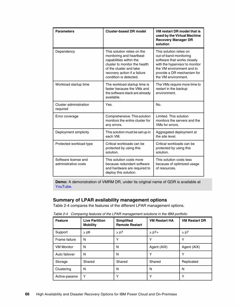
Summary of LPAR availability management optionsTable 2-4 compares the features of the different LPAR management options.
Table 2-4 Comparing features of the LPAR management solutions in the IBM portfolio
Dependency This solution relies on the monitoring and heartbeat capabilities within thecluster to monitor the health of the cluster and take recovery action if a failure condition is detected.
This solution relies on out-of-band monitoring software that works closely with the hypervisor to monitor the VM environment and to provide a DR mechanism for the VM environment.
Workload startup time The workload startup time is faster because the VMs and the software stack are already available.
The VMs require more time to restart in the backup environment.
Cluster administration required
Yes. No.
Error coverage Comprehensive. This solution monitors the entire cluster for any errors.
Limited. This solution monitors the servers and the VMs for errors.
Deployment simplicity This solution must be set up in each VM.
Aggregated deployment at the site level.
Protected workload type Critical workloads can be protected by using this solution.
Critical workloads can be protected by using this solution.
Software license and administrative costs
This solution costs more because redundant software and hardware are required to deploy this solution.
This solution costs less because of optimized usage of resources.
Demo: A demonstration of VMRM DR, under its original name of GDR is available at YouTube.
Feature Live Partition Mobility
Simplified Remote Restart
VM Restart HA VM Restart DR
Support > p6 > p7 > p7+ > p7
Frame failure N Y Y Y
VM Monitor N N Agent (AIX) Agent (AIX)
Auto failover N N Y Y
Storage Shared Shared Shared Replicated
Clustering N N N N
Active-passive Y Y Y Y
Parameters Cluster-based DR model VM restart DR model that is used by the Virtual Machine Recovery Manager DR solution
66 High Availability and Disaster Recovery Options for IBM Power Cloud and On-Premises
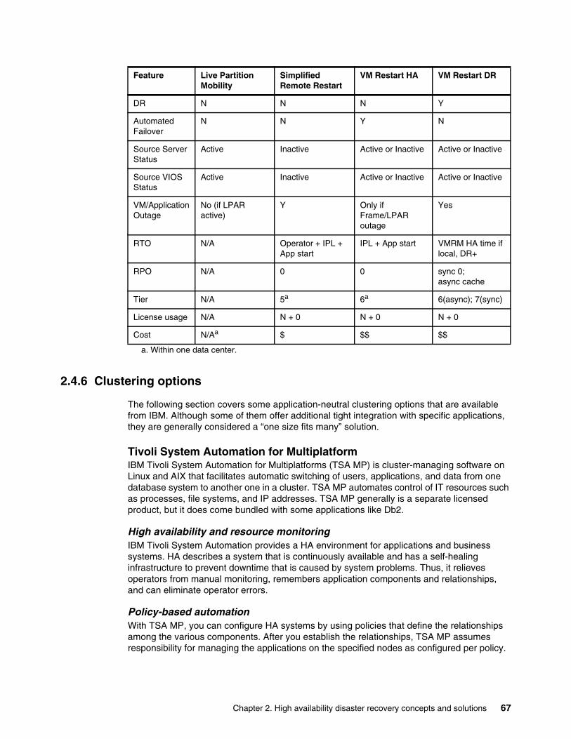
2.4.6 Clustering options
The following section covers some application-neutral clustering options that are available from IBM. Although some of them offer additional tight integration with specific applications, they are generally considered a “one size fits many” solution.
Tivoli System Automation for MultiplatformIBM Tivoli System Automation for Multiplatforms (TSA MP) is cluster-managing software on Linux and AIX that facilitates automatic switching of users, applications, and data from one database system to another one in a cluster. TSA MP automates control of IT resources such as processes, file systems, and IP addresses. TSA MP generally is a separate licensed product, but it does come bundled with some applications like Db2.
High availability and resource monitoringIBM Tivoli System Automation provides a HA environment for applications and business systems. HA describes a system that is continuously available and has a self-healing infrastructure to prevent downtime that is caused by system problems. Thus, it relieves operators from manual monitoring, remembers application components and relationships, and can eliminate operator errors.
Policy-based automationWith TSA MP, you can configure HA systems by using policies that define the relationships among the various components. After you establish the relationships, TSA MP assumes responsibility for managing the applications on the specified nodes as configured per policy.
DR N N N Y
Automated Failover
N N Y N
Source Server Status
Active Inactive Active or Inactive Active or Inactive
Source VIOS Status
Active Inactive Active or Inactive Active or Inactive
VM/Application Outage
No (if LPAR active)
Y Only if Frame/LPAR outage
Yes
RTO N/A Operator + IPL + App start
IPL + App start VMRM HA time if local, DR+
RPO N/A 0 0 sync 0;async cache
Tier N/A 5a 6a 6(async); 7(sync)
License usage N/A N + 0 N + 0 N + 0
Cost N/Aa $ $$ $$
a. Within one data center.
Feature Live Partition Mobility
Simplified Remote Restart
VM Restart HA VM Restart DR
Chapter 2. High availability disaster recovery concepts and solutions 67
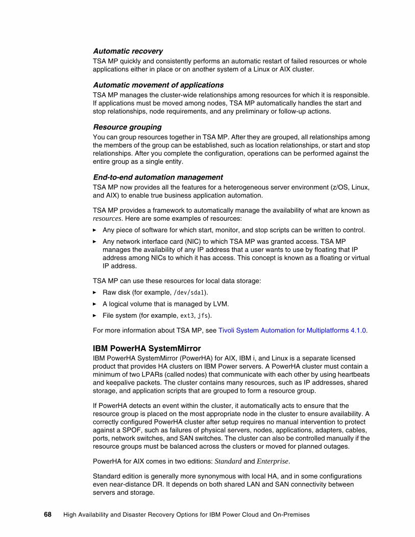
Automatic recoveryTSA MP quickly and consistently performs an automatic restart of failed resources or whole applications either in place or on another system of a Linux or AIX cluster.
Automatic movement of applicationsTSA MP manages the cluster-wide relationships among resources for which it is responsible. If applications must be moved among nodes, TSA MP automatically handles the start and stop relationships, node requirements, and any preliminary or follow-up actions.
Resource groupingYou can group resources together in TSA MP. After they are grouped, all relationships among the members of the group can be established, such as location relationships, or start and stop relationships. After you complete the configuration, operations can be performed against the entire group as a single entity.
End-to-end automation managementTSA MP now provides all the features for a heterogeneous server environment (z/OS, Linux, and AIX) to enable true business application automation.
TSA MP provides a framework to automatically manage the availability of what are known as resources. Here are some examples of resources:
� Any piece of software for which start, monitor, and stop scripts can be written to control.
� Any network interface card (NIC) to which TSA MP was granted access. TSA MP manages the availability of any IP address that a user wants to use by floating that IP address among NICs to which it has access. This concept is known as a floating or virtual IP address.
TSA MP can use these resources for local data storage:
� Raw disk (for example, /dev/sda1).
� A logical volume that is managed by LVM.
� File system (for example, ext3, jfs).
For more information about TSA MP, see Tivoli System Automation for Multiplatforms 4.1.0.
IBM PowerHA SystemMirror IBM PowerHA SystemMirror (PowerHA) for AIX, IBM i, and Linux is a separate licensed product that provides HA clusters on IBM Power servers. A PowerHA cluster must contain a minimum of two LPARs (called nodes) that communicate with each other by using heartbeats and keepalive packets. The cluster contains many resources, such as IP addresses, shared storage, and application scripts that are grouped to form a resource group.
If PowerHA detects an event within the cluster, it automatically acts to ensure that the resource group is placed on the most appropriate node in the cluster to ensure availability. A correctly configured PowerHA cluster after setup requires no manual intervention to protect against a SPOF, such as failures of physical servers, nodes, applications, adapters, cables, ports, network switches, and SAN switches. The cluster can also be controlled manually if the resource groups must be balanced across the clusters or moved for planned outages.
PowerHA for AIX comes in two editions: Standard and Enterprise.
Standard edition is generally more synonymous with local HA, and in some configurations even near-distance DR. It depends on both shared LAN and SAN connectivity between servers and storage.
68 High Availability and Disaster Recovery Options for IBM Power Cloud and On-Premises
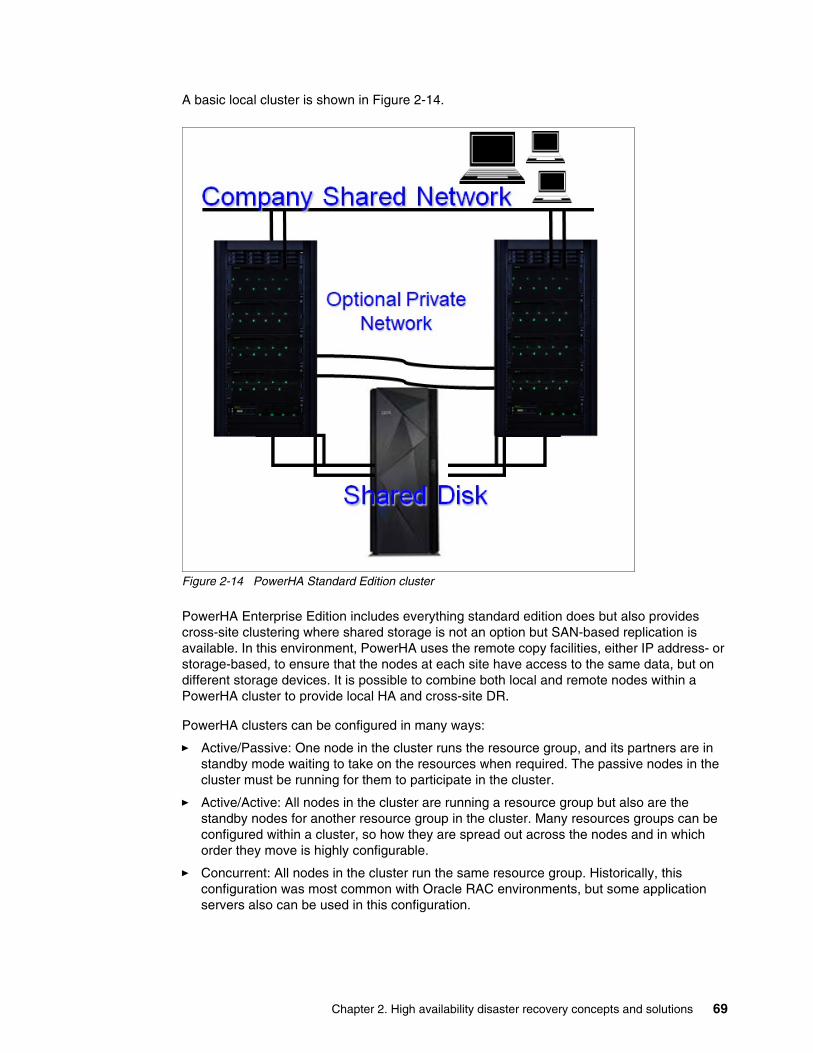
A basic local cluster is shown in Figure 2-14.
Figure 2-14 PowerHA Standard Edition cluster
PowerHA Enterprise Edition includes everything standard edition does but also provides cross-site clustering where shared storage is not an option but SAN-based replication is available. In this environment, PowerHA uses the remote copy facilities, either IP address- or storage-based, to ensure that the nodes at each site have access to the same data, but on different storage devices. It is possible to combine both local and remote nodes within a PowerHA cluster to provide local HA and cross-site DR.
PowerHA clusters can be configured in many ways:
� Active/Passive: One node in the cluster runs the resource group, and its partners are in standby mode waiting to take on the resources when required. The passive nodes in the cluster must be running for them to participate in the cluster.
� Active/Active: All nodes in the cluster are running a resource group but also are the standby nodes for another resource group in the cluster. Many resources groups can be configured within a cluster, so how they are spread out across the nodes and in which order they move is highly configurable.
� Concurrent: All nodes in the cluster run the same resource group. Historically, this configuration was most common with Oracle RAC environments, but some application servers also can be used in this configuration.
Chapter 2. High availability disaster recovery concepts and solutions 69
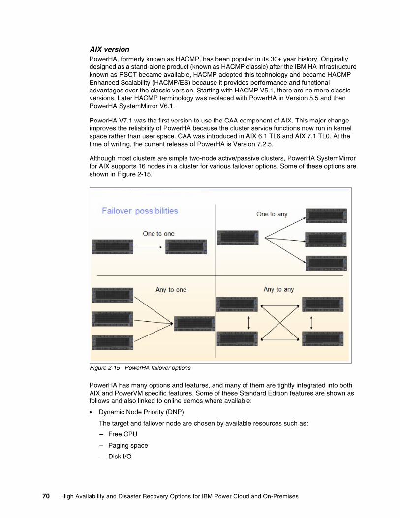
AIX versionPowerHA, formerly known as HACMP, has been popular in its 30+ year history. Originally designed as a stand-alone product (known as HACMP classic) after the IBM HA infrastructure known as RSCT became available, HACMP adopted this technology and became HACMP Enhanced Scalability (HACMP/ES) because it provides performance and functional advantages over the classic version. Starting with HACMP V5.1, there are no more classic versions. Later HACMP terminology was replaced with PowerHA in Version 5.5 and then PowerHA SystemMirror V6.1.
PowerHA V7.1 was the first version to use the CAA component of AIX. This major change improves the reliability of PowerHA because the cluster service functions now run in kernel space rather than user space. CAA was introduced in AIX 6.1 TL6 and AIX 7.1 TL0. At the time of writing, the current release of PowerHA is Version 7.2.5.
Although most clusters are simple two-node active/passive clusters, PowerHA SystemMirror for AIX supports 16 nodes in a cluster for various failover options. Some of these options are shown in Figure 2-15.
Figure 2-15 PowerHA failover options
PowerHA has many options and features, and many of them are tightly integrated into both AIX and PowerVM specific features. Some of these Standard Edition features are shown as follows and also linked to online demos where available:
� Dynamic Node Priority (DNP)
The target and fallover node are chosen by available resources such as:
– Free CPU
– Paging space
– Disk I/O
70 High Availability and Disaster Recovery Options for IBM Power Cloud and On-Premises
� Dynamic LPAR with extra CPU or memory during startup or fallover
Includes resource-optimized failovers by using Enterprise Pools (Resource-Optimized High Availability (ROHA))
� LPM awareness
� Live Kernel Update awareness
� Resource group dependencies
Great for multitier environments:
– Parent/child
– Same node or same site
– Different node or site
� Resource group priorities:
– Low
– Intermediate
– High
� AIX LVM or Enhanced Journaled File System (JFS2) specialized option utilization:
– File system Concurrent Mount Protection, also known as Mount Guard
– Active/Passive mode of concurrent volume groups
� Non-disruptive cluster updates and upgrades by using cl_ezupdate
� NovaLink managed LPAR support
� Rootvg and critical volume group loss detection
� User-defined events
� Customizable processing order
� Automatic repository replacement
� Cluster testing, both automated and customizable
� Delayed Fallback Timer
Enterprise Edition provides additional integrated support that primarily focuses on DR. Some of these features are:
� IP-based replication and GLVM
� IBM Spectrum Virtualize Storage Replication:
– Metro Mirror– Global Mirror– HyperSwap
� Dell EMC: Symmetrix Remote Data Facility (SRDF) (Synchronous or Asynchronous)
� Hitachi:
– TrueCopy for synchronous– Hitachi Universal Replicator for asynchronous
� IBM XIV®: Remote Mirror
� User confirmation on split site failure
� Site-specific service addresses
Chapter 2. High availability disaster recovery concepts and solutions 71
For more information about planning, installing, and configuring PowerHA SystemMirror for AIX, see the following resources:
� IBM PowerHA SystemMirror for AIX Cookbook, SG24-7739
� Guide to IBM PowerHA SystemMirror for AIX Version 7.1.3, SG24-8167
� IBM System Storage Solutions Handbook, SG24-5250
� PowerHA SystemMirror 7.2 for AIX
IBM i versionPowerHA SystemMirror for IBM i has been around since 2008 and shares many similarities with the AIX version. It is deeply integrated into IBM i and hardware-dependent System Licensed Internal Code (SLIC). However, it offers three editions: Express, Standard, and Enterprise.
� Express Edition enables single-node, full-system HyperSwap with the IBM DS8700 server, which provides continuously available storage through either planned or unplanned storage outage events.
� Standard Edition is generally for local data center HA.
� Enterprise Edition for multi-site DR solutions.
PowerHA for IBM i cluster configurations are also flexible. It is becoming more common for IBM i customers to deploy multi-site PowerHA clusters where the data is replicated either by IBM storage or by IBM i Geographic Mirroring. PowerHA integrates the IBM i OS with storage replication technologies that provide solutions that meet the HA needs of clients regardless of size.
Configurations range from a simple two-system, two-site cluster that uses IBM i Geographic Mirroring with internal storage to an IBM FlashSystem cluster or a three-site HyperSwap cluster with DS8000 storage. Using IBM storage adds the additional benefit of FlashCopy, which is used to eliminate the backup window, conduct query operations, and create point in time copies for data protection purposes.
The production data, including the local journals, is contained within an IASP, and planned switchovers between nodes in the cluster consists of a single command. Unplanned failovers can be configured to be automatic and require minimal operator intervention. The administration domain takes care of synchronizing security and configuration objects, such as user profiles. All these tasks are done with integration between PowerHA and the IBM i OS, and there is no dependency on third-party replication tools. Because there is at least one active OS on each node in the cluster, you can conduct software maintenance and OS upgrades on an alternative node without disrupting production.
Implementing IASPs is a simple task consisting of moving your application libraries and Integrated File System (IFS) data into the IASP, thus separating business data from the OS. The application binary files do not change, and most users are unaware of the migration in their daily workflow because their jobs automatically have access to libraries both in the system ASP and the IASP simultaneously.
Demonstration: A demonstration of PowerHA for IBM i that uses IBM i Geographic Mirroring can be found at YouTube.
72 High Availability and Disaster Recovery Options for IBM Power Cloud and On-Premises
For more information about planning, installing, and configuring PowerHA SystemMirror for IBM i, see the following resources:
� PowerHA SystemMirror for IBM i Cookbook, SG24-7994
� IBM PowerHA SystemMirror for i: Preparation (Volume 1 of 4), SG24-8400
� IBM PowerHA SystemMirror for i: Using DS8000 (Volume 2 of 4), SG24-8403
� IBM PowerHA SystemMirror for i: Using IBM Storwize (Volume 3 of 4), SG24-8402
� IBM PowerHA SystemMirror for i: Using Geographic Mirroring (Volume 4 of 4), SG24-8401
� IBM PowerHA SystemMirror for IBM i version support
LinuxThe PowerHA SystemMirror for Linux offering was withdrawn from marketing as of September 29, 2020. The official IBM replacement is VMRM HA, but its RTO is higher than general clustering.
For more information about PowerHA SystemMirror for Linux, see the following resources:
� IBM PowerHA SystemMirror V7.2.3 for IBM AIX and V7.22 for Linux, SG24-8434
� PowerHA SystemMirror 7.2 for Linux
More HA offerings for Linux are listed in the following sections.
Red Hat High Availability Add-OnThe Red Hat High Availability Add-On is a clustered system that provides reliability, availability, and serviceability (RAS) to critical production services. It consists of several components, and the major components are as follows:
� Cluster infrastructure
Provides fundamental functions for nodes to work together as a cluster, that is, configuration file management, membership management, lock management, and fencing.
� HA service management
Provides failover of services from one cluster node to another node if a node becomes inoperative.
� Cluster administration tool
Configuration and management tools for setting up, configuring, and managing the High Availability Add-On. The tools are uses with the cluster infrastructure components, the HA and service management components, and storage.
You can supplement the High Availability Add-On with the following components:
� Red Hat Global File System 2 (GFS2)
Part of the IBM Resilient® Storage Add-On, this component provides a cluster file system for use with the High Availability Add-On. GFS2 allows multiple nodes to share storage at a block level as though the storage were connected locally to each cluster node. A GFS2 cluster file system requires a cluster infrastructure.
Chapter 2. High availability disaster recovery concepts and solutions 73
� LVM Locking Daemon (lvmlockd)
Part of the Resilient Storage Add-On, this component provides volume management of cluster storage. lvmlockd support also requires a cluster infrastructure.
� HAProxy
Routing software that provides HA load balancing and failover in layer 4 (TCP) and layer 7 (HTTP and HTTPS) services.
PacemakerPacemaker is a cluster resource manager. It achieves maximum availability for your cluster services and resources by using the cluster infrastructure’s messaging and membership capabilities to deter and recover from node and resource-level failure.
Pacemaker is composed of separate component daemons that monitor cluster membership, scripts that manage the services, and resource management subsystems that monitor the disparate resources.
The following components form the Pacemaker architecture:
� Cluster Information Base (CIB)
The Pacemaker information daemon, which uses XML internally to distribute and synchronize the current configuration and status information from the Designated Coordinator (DC) to all other cluster nodes. The DC is a node that is assigned by Pacemaker to store and distribute the cluster state and actions by using the CIB.
� Cluster Resource Management Daemon (CRMd)
Pacemaker cluster resource actions are routed through this daemon. Resources that are managed by CRMd can be queried by client systems, and moved, instantiated, and changed when needed.
Each cluster node also includes a local resource manager daemon (LRMd) that acts as an interface between CRMd and resources. LRMd passes commands from CRMd to agents, such as starting and stopping and relaying status information.
� Shoot the Other Node in the Head (STONITH)
STONITH is the Pacemaker fencing implementation. It acts as a cluster resource in Pacemaker that processes fence requests, forcefully shutting down nodes and removing them from the cluster to ensure data integrity. STONITH is configured in the CIB and can be monitored as a normal cluster resource.
� corosync
corosync is the component, and a daemon of the same name, that serves the core membership and member-communication needs for HA clusters. It is required for the High Availability Add-On to function.
In addition to those membership and messaging functions, corosync also performs the following tasks:
– Manages quorum rules and determination.
– Provides messaging capabilities for applications that coordinate or operate across multiple members of the cluster and thus must communicate stateful or other information between instances.
– Uses the kronosnet library as its network transport to provide multiple redundant links and automatic failover.
74 High Availability and Disaster Recovery Options for IBM Power Cloud and On-Premises
� pcs
The pcs CLI controls and configures Pacemaker and the corosync heartbeat daemon. A CLI-based program, pcs can perform the following cluster management tasks:
– Create and configure a Pacemaker and corosync cluster.
– Modify the configuration of the cluster while it is running.
– Remotely configure both Pacemaker and corosync and start, stop, and display the status information of the cluster.
� pcsd Web UI
A GUI that you can use to create and configure Pacemaker and corosync clusters.
For more information about RHEL HA clustering on IBM Power servers, see Support Policies for Red Hat Enterprise Linux HA Clusters - IBM Power Virtual Server VMs as Cluster Members.
Red Hat OpenShift Container Platform clusterRed Hat OpenShift is available on Linux and AIX LPARs for both on-premises and in the cloud with IBM Power Virtual Server.
For more information about planning, installing, and configuring Red Hat OpenShift Container Platform clusters on IBM Power servers, see Installing a cluster on IBM Power Systems.
SUSE Linux Enterprise Server high availability extension SUSE Linux Enterprise Server HA works like PowerHA SystemMirror for AIX, as a simple comparison. There are virtual IP addresses, resource groups, heartbeat disks, and networks. Cluster internals, virtual IP address placement and failover, and takeover operations are managed, operated, and controlled from within SUSE Linux Enterprise Server HA.
For more information about the SUSE Linux Enterprise Server HA extension, see SUSE Linux Enterprise High Availability Extension.
Ubuntu Ubuntu also offers numerous packages to create tailored HA solutions. For more information about Ubuntu HA core and community packages, see Introduction to High Availability.
Summary of clustering optionsTable 2-5 compares the features of the different clustering options that were described in this chapter.
Table 2-5 Comparing features of the HADR clustering options
Feature Tivoli Systems Automation
PowerHA PowerHA SystemMirror Enterprise Edition
Linux clustering and Pacemaker
Support > p6 > p6 > p6 > p8
Frame failure Y Y Y Y
VM Monitor Y Y Y Y
Auto failover Y Y Y Y
Storage Shared Shared Replicated Replicated
Clustering Y Y Y Y
Chapter 2. High availability disaster recovery concepts and solutions 75
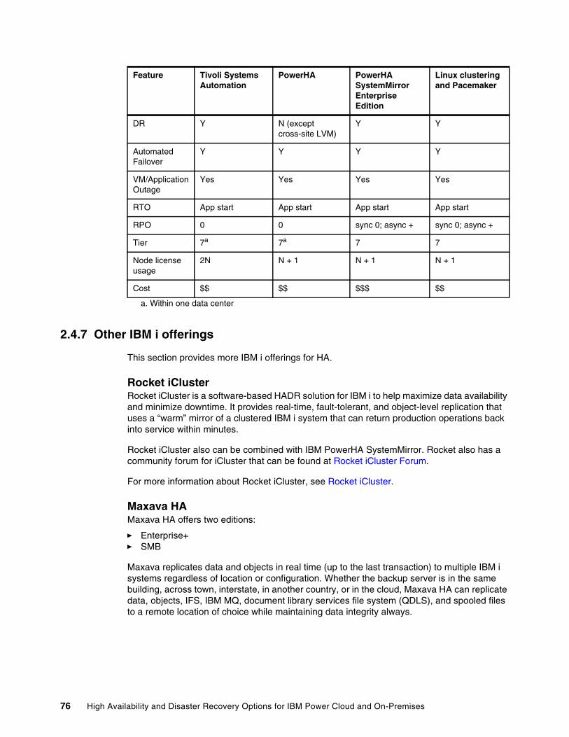
2.4.7 Other IBM i offerings
This section provides more IBM i offerings for HA.
Rocket iClusterRocket iCluster is a software-based HADR solution for IBM i to help maximize data availability and minimize downtime. It provides real-time, fault-tolerant, and object-level replication that uses a “warm” mirror of a clustered IBM i system that can return production operations back into service within minutes.
Rocket iCluster also can be combined with IBM PowerHA SystemMirror. Rocket also has a community forum for iCluster that can be found at Rocket iCluster Forum.
For more information about Rocket iCluster, see Rocket iCluster.
Maxava HAMaxava HA offers two editions:
� Enterprise+� SMB
Maxava replicates data and objects in real time (up to the last transaction) to multiple IBM i systems regardless of location or configuration. Whether the backup server is in the same building, across town, interstate, in another country, or in the cloud, Maxava HA can replicate data, objects, IFS, IBM MQ, document library services file system (QDLS), and spooled files to a remote location of choice while maintaining data integrity always.
DR Y N (except cross-site LVM)
Y Y
Automated Failover
Y Y Y Y
VM/Application Outage
Yes Yes Yes Yes
RTO App start App start App start App start
RPO 0 0 sync 0; async + sync 0; async +
Tier 7a 7a 7 7
Node license usage
2N N + 1 N + 1 N + 1
Cost $$ $$ $$$ $$
a. Within one data center
Feature Tivoli Systems Automation
PowerHA PowerHA SystemMirror Enterprise Edition
Linux clustering and Pacemaker
76 High Availability and Disaster Recovery Options for IBM Power Cloud and On-Premises
Built on native IBM i Remote Journaling, Maxava HA keeps the impact on the production server to an absolute minimum and comes complete with features that include the following ones:
� A highly functional GUI that is usable for both the initial configuration and day-to-day monitoring.
� Unlimited concurrent apply processing that is built to handle enterprise-level transactional volumes.
� Multi-Threaded IFS, which dynamically runs multiple IFS replication processes in parallel, increasing throughput so that replication is dramatically faster and more efficient in high-volume IFS environments.
� With Simulated Role Swaps (SRS), users can test their DR plan without downtime. SRS temporarily turns a backup system into a simulated primary system for role-swap readiness testing while the primary system remains live and unaffected.
� Multi-Node Role Swap enables role swaps for customers with multiple target IBM i systems, which can include hardware replication options such as PowerHA.
� With Remote Role Swap Capability, admins can perform role swaps (in either direction) by using a command or a mobile device.
� With Flexible Autonomics, users can design their own self-healing requirements.
� User-definable audits ensure data integrity always.
� The Command Scripting Function enables a predefined set of commands that are run at failover to minimize role-swap times.
For more information about Maxava HA, see Maxava HA.
Assure MIMIXAssure MIMIX provides full-featured, scalable HADR solutions by using real-time logical replication. Assure MIMIX is IBM i journal-based and includes extensive options for automating administration, comprehensive monitoring and alerting, data verification, customizable switch automation, and an easy to use GUI.
Assure MIMIX works with any combination of IBM i server, storage, and OS versions. It can provide HADR protection for one IBM i server or a multi-site mix of on-premises, remotely hosted, and cloud service-based systems. Assure MIMIX provides data protection and business continuity to help minimize planned and unplanned downtime.
Assure MIMIX can be combined with IBM PowerHA SystemMirror, Db2mirror, and switchable IASPs to provide options to manage risk and downtime.
For more information about Assure MIMIX, see Assure MIMIX.
Assure iTERA and Assure QuickEDDAssure iTERA and Assure QuickEDD provide HADR solutions by using real-time logical replication. They replicate IBM i data and objects in real time to local or remote backup servers. These servers stand ready to assume the production role. Assure iTERA and Assure QuickEDD also can be used with various IBM i OS levels and storage combinations, and they are scalable from SMB to enterprise workloads.
For more information about Assure iTERA, see Assure iTERA. For more information about Assure QuickEDD, see Assure QuickEDD HA.
Chapter 2. High availability disaster recovery concepts and solutions 77
Robot HARobot HA is a software-based HA solution for IBM i 7.2 or later that replicates important data by using IBM i remote journaling to provide business continuity. Robot HA can provide a fast, unplanned switchover to a target system, which ideally is at a remote location. The typical RTO is 15 - 30 minutes.
Robot HA provides many flexible options about how and what to replicate:
� Many-to-one� One-to-many� Object broadcast� Different library names� Only certain libraries� Only certain IFS directories
It also provides the following features:
� Simplified role swap for both audits and testing� Automatic resync� Automatic monitoring
Robot HA can be combined with IBM PowerHA SystemMirror.
For more information about Robot HA, see Robot HA: High Availability Software for IBM i.
78 High Availability and Disaster Recovery Options for IBM Power Cloud and On-Premises
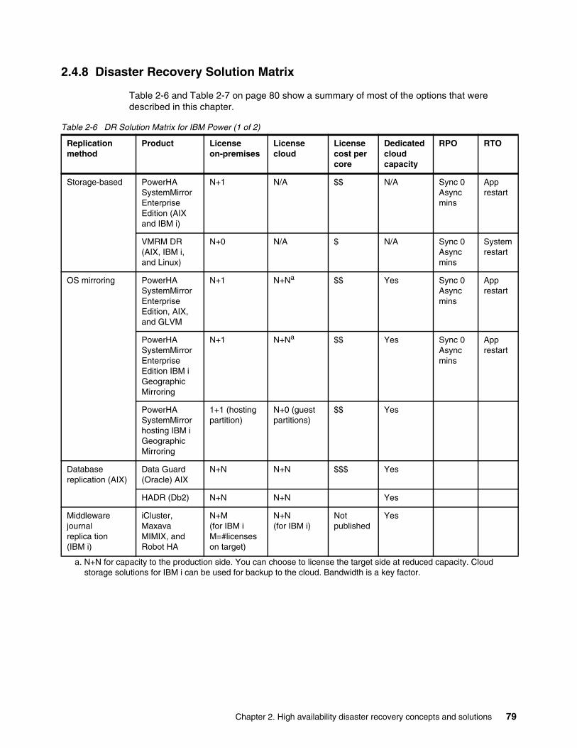
2.4.8 Disaster Recovery Solution Matrix
Table 2-6 and Table 2-7 on page 80 show a summary of most of the options that were described in this chapter.
Table 2-6 DR Solution Matrix for IBM Power (1 of 2)
Replication method
Product License on-premises
License cloud
License cost per core
Dedicated cloud capacity
RPO RTO
Storage-based PowerHA SystemMirror Enterprise Edition (AIX and IBM i)
N+1 N/A $$ N/A Sync 0 Async mins
App restart
VMRM DR (AIX, IBM i, and Linux)
N+0 N/A $ N/A Sync 0 Async mins
System restart
OS mirroring PowerHA SystemMirror Enterprise Edition, AIX, and GLVM
N+1 N+Na
a. N+N for capacity to the production side. You can choose to license the target side at reduced capacity. Cloud storage solutions for IBM i can be used for backup to the cloud. Bandwidth is a key factor.
$$ Yes Sync 0 Async mins
App restart
PowerHA SystemMirror Enterprise Edition IBM i Geographic Mirroring
N+1 N+Na $$ Yes Sync 0 Async mins
App restart
PowerHA SystemMirror hosting IBM i Geographic Mirroring
1+1 (hosting partition)
N+0 (guest partitions)
$$ Yes
Database replication (AIX)
Data Guard (Oracle) AIX
N+N N+N $$$ Yes
HADR (Db2) N+N N+N Yes
Middleware journal replica tion (IBM i)
iCluster, Maxava MIMIX, and Robot HA
N+M (for IBM i M=#licenses on target)
N+N (for IBM i)
Not published
Yes
Chapter 2. High availability disaster recovery concepts and solutions 79
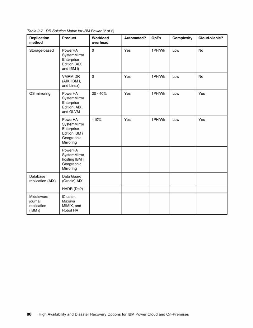
Table 2-7 DR Solution Matrix for IBM Power (2 of 2)
Replication method
Product Workload overhead
Automated? OpEx Complexity Cloud-viable?
Storage-based PowerHA SystemMirror Enterprise Edition (AIX and IBM i)
0 Yes 1PH/Wk Low No
VMRM DR (AIX, IBM i, and Linux)
0 Yes 1PH/Wk Low No
OS mirroring PowerHA SystemMirror Enterprise Edition, AIX, and GLVM
20 - 40% Yes 1PH/Wk Low Yes
PowerHA SystemMirror Enterprise Edition IBM i Geographic Mirroring
~10% Yes 1PH/Wk Low Yes
PowerHA SystemMirror hosting IBM i Geographic Mirroring
Database replication (AIX)
Data Guard (Oracle) AIX
HADR (Db2)
Middleware journal replication (IBM i)
iCluster, Maxava MIMIX, and Robot HA
80 High Availability and Disaster Recovery Options for IBM Power Cloud and On-Premises
Chapter 3. Scenarios
This chapter provides a series of case scenarios that illustrate high availability disaster recovery (HADR) solutions.
This chapter contains the following topics:
� 3.1, “PowerHA for AIX cross-site Logical Volume Manager mirroring” on page 82� 3.2, “Stand-alone Geographic Logical Volume Manager” on page 89� 3.3, “PowerHA for AIX Enterprise Edition with GLVM” on page 97� 3.4, “PowerHA for AIX Enterprise Edition with HyperSwap” on page 98� 3.5, “IBM Virtual Machine Recovery Manager high availability” on page 102� 3.6, “Virtual Machine Recovery Manager disaster recovery” on page 105� 3.7, “IBM Tivoli System Automation for Multiplatform” on page 107� 3.8, “IBM Spectrum Scale stretched cluster” on page 109
3
© Copyright IBM Corp. 2022. 81
3.1 PowerHA for AIX cross-site Logical Volume Manager mirroring
This section describes a disaster recovery (DR) solution that is based on AIX Logical Volume Manager (LVM) mirroring and a stretched PowerHA cluster. It is built from the same components that are used for local cluster solutions with storage area network (SAN)-attached storage. Cross-site LVM mirroring replicates data across the SAN between the disk subsystems at separate sites, and PowerHA provides automated failover in a failure. This solution can provide a recovery point objective (RPO) of zero and a recovery time objective (RTO) of minutes. The biggest determining factor in recovery time is application recovery and restart time.
Remote disks can be combined into a volume group by using the AIX LVM, and this volume group can be imported into the nodes at different sites. You can create logical volumes and set up an LVM mirror with a copy at each site. Although LVM mirroring supports up to three copies, PowerHA supports only two sites. However, it is possible to have two LVM copies locally, even two servers, locally at one site and one remote copy at another site.
Although it is common to have the same storage type at each location, it is not a requirement, which is a perk for these configurations because they are storage type neutral. If the storage is supported for SAN attachment to AIX and provides adequate performance, it most likely is a valid candidate to be used in this configuration.
3.1.1 Compared to local cluster
The main difference between local clusters and clustered solutions with cross-site mirroring is as follows:
� For local clusters, generally all nodes and storage subsystems are in the same location.
� With cross-site mirroring, cluster nodes and storage subsystems are at two different site locations. Each site has at least one cluster node and one storage subsystem with all the necessary IP network and SAN infrastructure.
This solution offers automation of AIX LVM mirroring within SAN disk subsystems between different sites. It also provides automatic LVM mirroring synchronization and disk device activation when, after a disk or site failure, a node or disk becomes available.
Each node in a cross-site LVM cluster accesses all storage subsystems. The data availability is ensured through the LVM mirroring between the volumes residing on separate storage subsystems at different sites.
In a site failure, PowerHA performs a takeover of the resources to the secondary site according to the cluster policy configuration. It activates all defined volume groups from the surviving mirrored copy. If one storage subsystem fails, data access is not interrupted and applications can access data from the active mirroring copy the on surviving disk subsystem.
PowerHA drives automatic LVM mirroring synchronization, and after the failed site joins the cluster, it automatically fixes removed and missing volumes (PV states removed or missing) and synchronizes data. Automatic synchronization is not possible for all cases, but Cluster Single Point of Control (C-SPOC) can be used to synchronize the data from the surviving mirrors to stale mirrors after a disk or site failure.
82 High Availability and Disaster Recovery Options for IBM Power Cloud and On-Premises
3.1.2 General PowerHA requirements
The following AIX base operating system (BOS) components are prerequisites for PowerHA:
� bos.adt.lib� bos.adt.libm� bos.adt.syscalls� bos.ahafs� bos.cluster (Cluster Aware AIX (CAA))� bos.clvm.enh� bos.data� bos.net.tcp.client� bos.net.tcp.server� bos.rte.SRC� bos.rte.libc� bos.rte.libcfg� bos.rte.libcur� bos.rte.libpthreads� bos.rte.lvm� bos.rte.odm� devices.common.IBM.storfwork.rte (optional, but required for sancomm)� rsct.basic.rte� rsct.compat.basic.hacmp� rsct.compat.clients.hacmp� rsct.core.rmc
Cluster Aware AIXThe Cluster Aware function is part of the AIX operating system (OS). PowerHA SystemMirror 7.1 and later uses CAA services to configure, verify, and monitor the cluster topology. This feature is a major reliability improvement because core functions of the cluster services, such as topology-related services, now run in the kernel space, which makes it much less susceptible to being affected by the workload that is generated in the user space.
Repository disk CAA uses a shared disk, 512 MB - 460 GB to store its cluster configuration information. CAA requires a dedicated shared disk that is available to all nodes that are part of the cluster. This disk cannot be used for application storage or any other purpose.
As a best practice, the repository disk in a two-node cluster should be at least 1 GB and be RAID-protected.
Virtualization layerThis section describes the virtualization layer characteristics and considerations.
Important considerations for Virtual I/O ServerThis section lists some new features of AIX and Virtual I/O Server (VIOS) that help to increase overall availability. These features are especially useful for PowerHA environments.
Important: The repository is not supported for mirroring by LVM.
Chapter 3. Scenarios 83
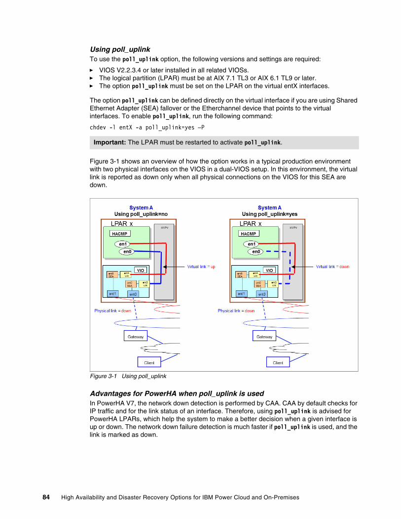
Using poll_uplinkTo use the poll_uplink option, the following versions and settings are required:
� VIOS V2.2.3.4 or later installed in all related VIOSs.� The logical partition (LPAR) must be at AIX 7.1 TL3 or AIX 6.1 TL9 or later.� The option poll_uplink must be set on the LPAR on the virtual entX interfaces.
The option poll_uplink can be defined directly on the virtual interface if you are using Shared Ethernet Adapter (SEA) fallover or the Etherchannel device that points to the virtual interfaces. To enable poll_uplink, run the following command:
chdev -l entX -a poll_uplink=yes –P
Figure 3-1 shows an overview of how the option works in a typical production environment with two physical interfaces on the VIOS in a dual-VIOS setup. In this environment, the virtual link is reported as down only when all physical connections on the VIOS for this SEA are down.
Figure 3-1 Using poll_uplink
Advantages for PowerHA when poll_uplink is usedIn PowerHA V7, the network down detection is performed by CAA. CAA by default checks for IP traffic and for the link status of an interface. Therefore, using poll_uplink is advised for PowerHA LPARs, which help the system to make a better decision when a given interface is up or down. The network down failure detection is much faster if poll_uplink is used, and the link is marked as down.
Important: The LPAR must be restarted to activate poll_uplink.
84 High Availability and Disaster Recovery Options for IBM Power Cloud and On-Premises
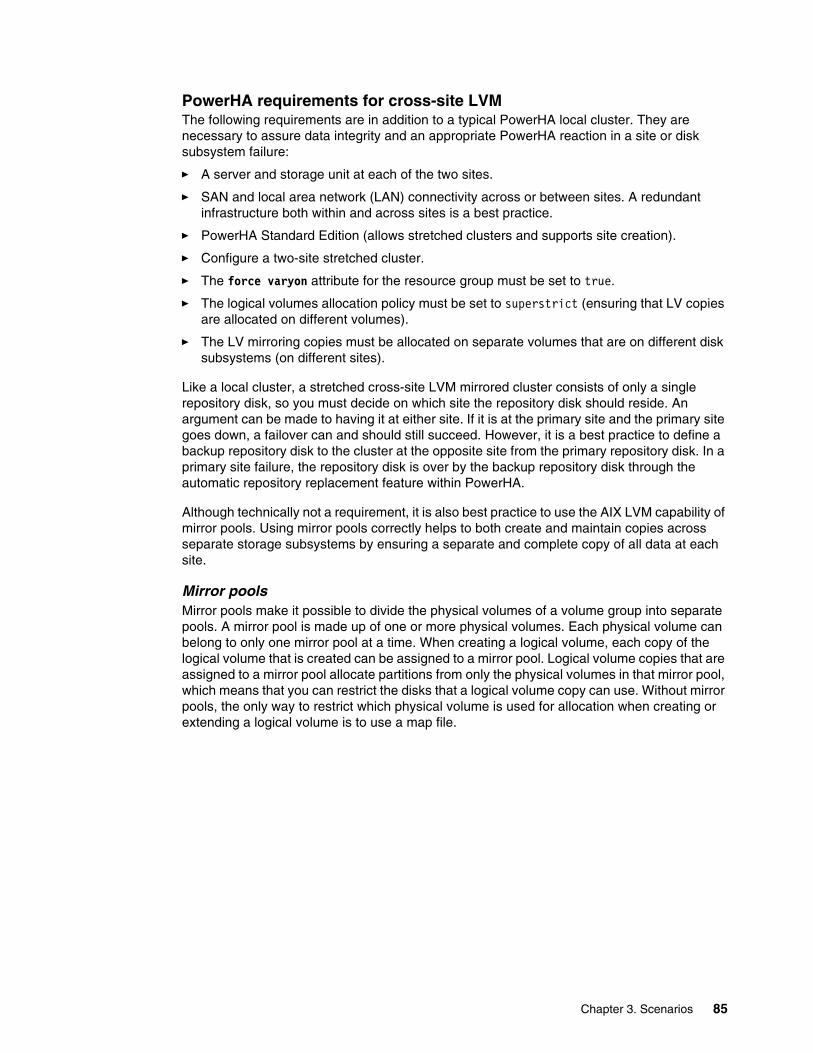
PowerHA requirements for cross-site LVMThe following requirements are in addition to a typical PowerHA local cluster. They are necessary to assure data integrity and an appropriate PowerHA reaction in a site or disk subsystem failure:
� A server and storage unit at each of the two sites.
� SAN and local area network (LAN) connectivity across or between sites. A redundant infrastructure both within and across sites is a best practice.
� PowerHA Standard Edition (allows stretched clusters and supports site creation).
� Configure a two-site stretched cluster.
� The force varyon attribute for the resource group must be set to true.
� The logical volumes allocation policy must be set to superstrict (ensuring that LV copies are allocated on different volumes).
� The LV mirroring copies must be allocated on separate volumes that are on different disk subsystems (on different sites).
Like a local cluster, a stretched cross-site LVM mirrored cluster consists of only a single repository disk, so you must decide on which site the repository disk should reside. An argument can be made to having it at either site. If it is at the primary site and the primary site goes down, a failover can and should still succeed. However, it is a best practice to define a backup repository disk to the cluster at the opposite site from the primary repository disk. In a primary site failure, the repository disk is over by the backup repository disk through the automatic repository replacement feature within PowerHA.
Although technically not a requirement, it is also best practice to use the AIX LVM capability of mirror pools. Using mirror pools correctly helps to both create and maintain copies across separate storage subsystems by ensuring a separate and complete copy of all data at each site.
Mirror poolsMirror pools make it possible to divide the physical volumes of a volume group into separate pools. A mirror pool is made up of one or more physical volumes. Each physical volume can belong to only one mirror pool at a time. When creating a logical volume, each copy of the logical volume that is created can be assigned to a mirror pool. Logical volume copies that are assigned to a mirror pool allocate partitions from only the physical volumes in that mirror pool, which means that you can restrict the disks that a logical volume copy can use. Without mirror pools, the only way to restrict which physical volume is used for allocation when creating or extending a logical volume is to use a map file.
Chapter 3. Scenarios 85
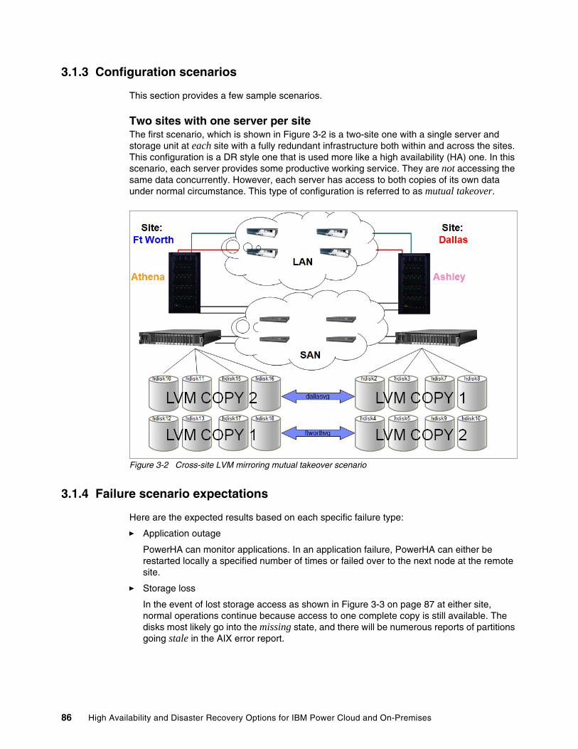
3.1.3 Configuration scenarios
This section provides a few sample scenarios.
Two sites with one server per siteThe first scenario, which is shown in Figure 3-2 is a two-site one with a single server and storage unit at each site with a fully redundant infrastructure both within and across the sites. This configuration is a DR style one that is used more like a high availability (HA) one. In this scenario, each server provides some productive working service. They are not accessing the same data concurrently. However, each server has access to both copies of its own data under normal circumstance. This type of configuration is referred to as mutual takeover.
Figure 3-2 Cross-site LVM mirroring mutual takeover scenario
3.1.4 Failure scenario expectations
Here are the expected results based on each specific failure type:
� Application outage
PowerHA can monitor applications. In an application failure, PowerHA can either be restarted locally a specified number of times or failed over to the next node at the remote site.
� Storage loss
In the event of lost storage access as shown in Figure 3-3 on page 87 at either site, normal operations continue because access to one complete copy is still available. The disks most likely go into the missing state, and there will be numerous reports of partitions going stale in the AIX error report.
86 High Availability and Disaster Recovery Options for IBM Power Cloud and On-Premises
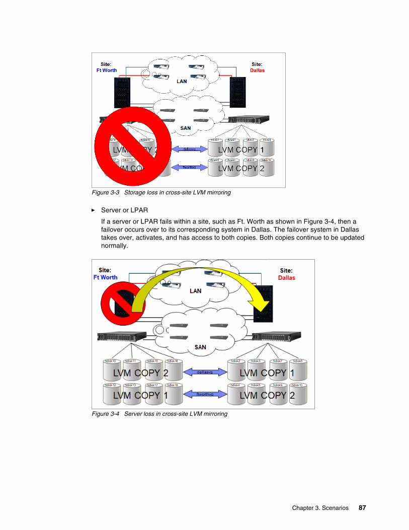
Figure 3-3 Storage loss in cross-site LVM mirroring
� Server or LPAR
If a server or LPAR fails within a site, such as Ft. Worth as shown in Figure 3-4, then a failover occurs over to its corresponding system in Dallas. The failover system in Dallas takes over, activates, and has access to both copies. Both copies continue to be updated normally.
Figure 3-4 Server loss in cross-site LVM mirroring
Chapter 3. Scenarios 87

� Site outage
In a site outage where both the storage and server are unavailable, as shown in Figure 3-5, then a failover occurs to the other site. The key difference is that now only one copy of the data is available, so the force varyon attribute for the resource group is needed. This attribute allows the failover server to start the volume group with only half the disks and one copy of data.
Figure 3-5 Site loss in cross-site LVM mirroring
Two sites, three servers, and two data copiesThis scenario is a continuation of the one in “Two sites with one server per site” on page 86. It adds another server locally to Ft. Worth to provide failover within the site first in a server outage, as shown in Figure 3-6 on page 89. All previous failure scenarios and expectations remain the same.
88 High Availability and Disaster Recovery Options for IBM Power Cloud and On-Premises
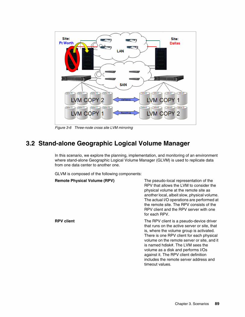
Figure 3-6 Three-node cross site LVM mirroring
3.2 Stand-alone Geographic Logical Volume Manager
In this scenario, we explore the planning, implementation, and monitoring of an environment where stand-alone Geographic Logical Volume Manager (GLVM) is used to replicate data from one data center to another one.
GLVM is composed of the following components:
Remote Physical Volume (RPV) The pseudo-local representation of the RPV that allows the LVM to consider the physical volume at the remote site as another local, albeit slow, physical volume. The actual I/O operations are performed at the remote site. The RPV consists of the RPV client and the RPV server with one for each RPV.
RPV client The RPV client is a pseudo-device driver that runs on the active server or site, that is, where the volume group is activated. There is one RPV client for each physical volume on the remote server or site, and it is named hdisk#. The LVM sees the volume as a disk and performs I/Os against it. The RPV client definition includes the remote server address and timeout values.
Chapter 3. Scenarios 89
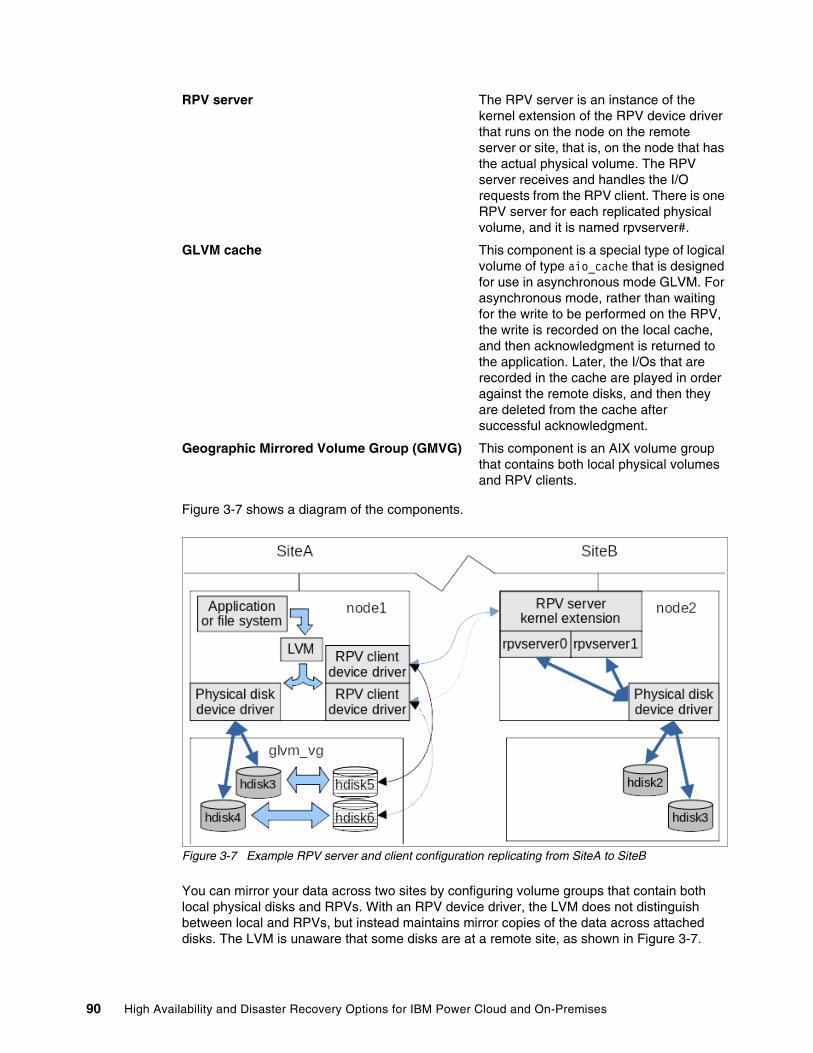
RPV server The RPV server is an instance of the kernel extension of the RPV device driver that runs on the node on the remote server or site, that is, on the node that has the actual physical volume. The RPV server receives and handles the I/O requests from the RPV client. There is one RPV server for each replicated physical volume, and it is named rpvserver#.
GLVM cache This component is a special type of logical volume of type aio_cache that is designed for use in asynchronous mode GLVM. For asynchronous mode, rather than waiting for the write to be performed on the RPV, the write is recorded on the local cache, and then acknowledgment is returned to the application. Later, the I/Os that are recorded in the cache are played in order against the remote disks, and then they are deleted from the cache after successful acknowledgment.
Geographic Mirrored Volume Group (GMVG) This component is an AIX volume group that contains both local physical volumes and RPV clients.
Figure 3-7 shows a diagram of the components.
Figure 3-7 Example RPV server and client configuration replicating from SiteA to SiteB
You can mirror your data across two sites by configuring volume groups that contain both local physical disks and RPVs. With an RPV device driver, the LVM does not distinguish between local and RPVs, but instead maintains mirror copies of the data across attached disks. The LVM is unaware that some disks are at a remote site, as shown in Figure 3-7.
90 High Availability and Disaster Recovery Options for IBM Power Cloud and On-Premises
For PowerHA SystemMirror installations, the GMVGs can be added to resource groups, and they are managed and monitored by PowerHA.
3.2.1 Planning
Before implementing GLVM between two data centers, you must consider the following items:
� AIX software requirements� Limitations� Sizing� Recommendations
AIX software requirementsAIX requires the following BOS components:
� glvm.rpv.client� glvm.rpv.server� glvm.rpv.util
LimitationsGLVM imposes the following limitations:
� The inter-disk allocation policy for logical volumes in AIX must be set to superstrict. This policy ensures that there is a complete mirror copy on each set of either local or RPVs. In GLVM, using the superstrict policy for mirroring ensures that when you create a mirrored logical volume, you always have a complete copy at each site.
� Up to three copies of the logical volumes can be created, with at least one mirror copy at each site. One of the sites may optionally contain a second copy. There will be extra considerations when moving back to the site with the two copies because the write to each copy is sent separately over the network.
� Two sites, with one local and one remote. If using PowerHA, GLVM site names must correspond with the PowerHA site names.
� The rootvg volume group cannot be geographically mirrored.
� Although asynchronous mode requires configuring mirror pools, it is a best practice for synchronous mode.
� The asynchronous GLVM volume group cannot contain an active paging space logical volume, and this volume is not recommended for synchronous GLVM.
� You must use scalable volume groups, which can be in non-concurrent or enhanced concurrent mode. Using enhanced concurrent volume groups is required for use with PowerHA but does not really provide an advantage for stand-alone GLVM. If you use enhanced concurrent stand-alone volume groups, there are extra steps to active the GMVG.
� The volume group should not be configured to auto-activate (varyon).
� Bad block relocation should be turned off. If a bad block is detected at one site and the block is relocated, then the block maps will differ between sites. This feature is required only for asynchronous replication because it impacts the playing of the cached I/O against the RPVs if the block maps differ.
� IP Security (IPsec) can be configured to secure the RPV client/server network traffic between the sites.
� 1 MB of available space is required in /usr before installation.
� Port 6192 TCP/UDP is open between the two servers.
Chapter 3. Scenarios 91
AIX LVM mirror poolsMirror pools are a way to divide the physical volumes in a volume group into distinct groups or pools and then control the placement of the LPAR mirrored copies. Mirror pools were introduced in AIX 6.1.1.0 and apply only to scalable volume groups. Mirror pool names must be fewer than 15 characters and are unique within a volume group.
A mirror pool is composed of one or more physical volumes, and each physical volume can belong only to one mirror pool at a time. When defining a logical volume, each copy of the logical volume can be assigned to a specific mirror pool to ensure that when a copy of a logical volume is assigned to a mirror pool, only partitions from physical volumes in that pool are allocated. Before the introduction of mirror pools, the only way you could extend logical volumes and guarantee that the partitions were allocated from the correct physical volume was to use a map file. Physical volumes can be assigned to a mirror pool by running chpv or extendvg.
There cannot be more than three mirror pools in each volume group, and each mirror pool must contain at least one complete copy of each logical volume that is defined in that pool.
Mirror pool strictness can be used to enforce tighter restrictions on the allocation of partitions in mirror pools. Mirror pool strictness can have one of the following values:
off The default setting. No restrictions apply to the use of the mirror pools.
on Each logical volume that is created in the volume group must have all copies assigned to mirror pools.
super Specifically for GLVM, and it ensure that local and RPVs cannot be assigned to the same mirror pool.
Mirror pool characteristics can be changed, but any changes do not affect currently allocated partitions. After you make any mirror pool changes, run the reorgvg command so that allocated partitions can be moved to conform to the mirror pool restrictions.
This mirror pools are used to ensure that the following items are true:
� Each site has complete copy of each mirrored logical volume in the GMVG.
� The cache logical volume for asynchronous GMVGs is configured and managed correctly.
Note: After mirror pools are defined, the volume group can no longer be imported into versions of AIX before AIX 6.1.1.0. If you use enhanced concurrent mode volume groups, all nodes in the cluster also must be later than AIX 6.1.1.0.
Note: AIX LVM Mirror pools are recommended only for synchronous mode, but are required for asynchronous mode.
92 High Availability and Disaster Recovery Options for IBM Power Cloud and On-Premises
SizingThere are many tools that you can use to examine the workload if GLVM is being planned for an existing application. Although network latency and throughput are critical to the performance on synchronous GLVM, it is also important in planning an asynchronous configuration.
� gmdsizing
A command to estimate network bandwidth requirements for GLVM networks. It was originally part of HAGeo and GeoRM, and it is part of the samples in PowerHA installations (it is in /usr/es/sbin/cluster/samples/gmdsizing/gmdsizing). It monitors disk utilization over the specified period and produces a report that is used as an aid for determining bandwidth requirements.
� lvmstat
Reports input/output statistics for LPARs, logical volumes, and volume groups. Also reports pbuf and blocked I/O statistics and allows pbuf allocation changes to volume groups.
lvmstat { -l | -v } Name [ -e | -d ] [ -F ] [ -C ] [ -c Count ] [ -s ] [ Interval [ Iterations ] ]
� iostat
Reports CPU statistics, asynchronous input/output (AIO) and input/output statistics for the entire system, adapters, tty devices, disks CD-ROMs, tapes, and file systems. Use flags -s and -f to show logical and disk I/O.
� Other tools
You can use general monitoring commands such as nmon and topas. For users that want a more graphical representation, statistics from rpvstat can be loaded into a time series database, such as influxDB, and then presented with a tool such as Grafana.
Cache planning (asynchronous mode)Asynchronous mode uses a local cache (a logical volume in the mirror pool) to store locally the updates to the remote logical volumes. The size of this cache is critical in two ways:
� Too large
The cache represents the maximum amount of data that can be lost in a disaster, so it must be planned. Roughly 2 GB of data in the cache represents 1 GB of updates for the remote system.
� Too small
After the local cache is full, GLVM suspends all local writes until space is cleared in the cache (updates are made to the remote copy). If there are sustained peaks in I/O activity greater than that which the network can handle, the cache fills faster than it can empty, eventually stopping local I/O until space can be cleared.
Planning for ongoing operationsBecause PowerHA SystemMirror will not be monitoring and managing the starting and stopping of the RPV servers and clients, this task falls to the administrator. Although many of these tasks can be scripted, careful checking must be done of the status of the environment before starting or stopping any services because GLVM has no awareness of the environment on which it is operating.
It is the task of the administrator to maintain the operations of the RPV servers and clients, monitor the health of the networks and the servers and LPARs, and set preferred read for the local disks.
Chapter 3. Scenarios 93
Planning quorumIn general, it is a best practice to disable quorum for GMVGs to minimize the possibility of the volume group going offline if access to the remote copy is lost. Therefore, you can keep operating in an inter-site network failure or maintenance activity on the remote site.
Planning for an increase in CPU loadImplementing GLVM increases the demand on system resources, so the following items must be accounted for in your planning:
� If compression is turned on, ensure that hardware compression is enabled (NX Crypto Accelerator) or compressing adds to CPU consumption on both the RPV client and server.
� Changes to io_grp_latency can increase CPU consumption.
� I/O wait increases for synchronous mode because of the delay that is introduced by acknowledgment from the RPV Server. There is a longer I/O code path, so a delay is introduced for asynchronous mode.
Tuning optionsThe rpvutil command has the following options for tuning the operation of GLVM:
� rpv_net_monitor=1|0
Setting rpv_net_monitor to 1 turns on monitoring of the RPV network by rpvutil so that the RPV client detects any network failures and attempts to resume after the network recovers. The default is 0 (disabled).
� compression=1|0
Before using compression, check that:
– Both the RPV client and the RPV server are running AIX 7.2.5 or later with all the latest RPV device drivers.
– Both the RPV server and the RPV client are IBM Power servers with NX842 acceleration units.
– The compression tunable parameter is enabled on both the RPV server and RPV client so that the I/O data packets are compressed when the workload is failed over between the RPV client and the RPV server.
When the compression tunable parameter is set to 1, the rpvutil command compresses the I/O data packet before it is sent from the RPV client to the RPV server by using the cryptography and compression units (NX842) on Power Servers servers. If the I/O data packet is compressed successfully, a flag is set in the data packet. When the RPV server receives a packet with the compressed flag set, the packet is decompressed. If the NX842 compression unit is not available, the RPV server attempts software decompression of the packet.
By default, this option is set to 0 (disabled).
� io_grp_latency=timeout_value (milliseconds)
Used to set the maximum expected delay before receiving the I/O acknowledgment for a mirror pool that is configured in asynchronous mode. The default delay value is 10 ms, and a lower value can be set to improve I/O performance but might cause higher CPU consumption.
Note: If you use PowerHA SystemMirror, it is a different situation because PowerHA detects quorum loss and manages the volume group.
Disabling quorum also requires setting forced varyon for the volume group in PowerHA.
94 High Availability and Disaster Recovery Options for IBM Power Cloud and On-Premises
� nw_sessions=<number of sessions> (1 - 99)
A new tunable (available in AIX 7.2.5.2) that controls the number of RPV sessions (sender and receiver threads) to be configured per network. This tunable is used to increase the number of parallel RPV sessions per GLVM network, which sends more data in parallel, improves the data transfer rate and more fully uses the network bandwidth.
Setting hardware compressionCheck that hardware compression is possible by running the command that is shown in Example 3-1.
Example 3-1 Checking the hardware compression capabilities
pcha1:/:# prtconf. . . NX Crypto Acceleration: Capable and Enabled. . .
Best practicesHere are some best practices that come from the team’s experiences:
� There are potential deadlocks if Mirror Write Consistency is set to active for asynchronous GMVG. As a best practice, use passive for both asynchronous and synchronous modes.
� Configure the RPV level I/O timeout value to avoid any issues that are related to network speed or I/O timeouts. This value can be modified when RPV disk is in a defined state. The default value is 180 seconds.
� AIX LVM allows the placement of disks in mirror pools and then selecting the read preference based on the mirror pool. A feature that was added for GLVM in PowerHA allows physical volumes to be added to sites and then the preferred read to be set to siteaffinity. This option is not available for stand-alone GLVM users, and they must set the LVM preferred read to the local mirror pool before activating the volume group.
� Turn off quorum and have multiple networks in PowerHA or Etherchannel in the stand-alone adapter. Ensure that all networks follow different paths and have no shared point of failure.
� rpvstat -n provides details about an individual network, and rpvstat -A provides details about AIO.
� For better performance, ensure that disk driver parameters are configured correctly for the storage that is deployed in your environment. For more information about setting those tunables (for example, queue_depth and num_cmd_elems), see the AIX and storage documentation.
In addition to these general best practices, here are some best practices for asynchronous mode:
� Asynchronous GLVM is supported only on scalable volume groups, which may be in enhanced concurrent mode.
� You can lower the timeout parameter for the RPV client to improve application response times, but balance this setting against latency problems. This value can be changed when the RPV client is in a defined state.
� Reducing the max_transfer size for the remote device while there is data in the AIO cache can cause remote I/O failures (lsattr -El hdiskX -a max_transfer).
Chapter 3. Scenarios 95
� In a stand-alone GLVM environment, you must ensure that all the backup disks in the secondary sites are in an active state before you bring the volume group online. During the online recovery of the volume group, if the RPV device driver detects that the RPV server is not online, it updates the cache disk with details about a failed request, and all subsequent I/Os are treated as synchronous. To convert back to asynchronous mode after the problem is rectified, you must first convert the mirror pool to synchronous mode and then back to asynchronous mode by using chmp.
� When an asynchronous GMVG it brought online, it performs a cache recovery. If previously the node halted abruptly, for example, because of a power outage, it is possible that the cache is not empty. In this case, cache recovery might take some time, depending on the amount of data in the cache and the network speed. No application writes may complete while cache recovery in progress to handle consistency at remote site. In this case, the application users might observe a pause.
� After a site failure, the asynchronous mirror state on the remote site is inactive. After integrating back with the primary site, the mirror pool must be converted to synchronous and then back to asynchronous to continue in asynchronous mode.
� Monitor regularly whether the asynchronous mirroring state of the GLVM is active by using the lsmp command.
� The rpvstat -C command provides details about the I/O cache monitor, and rpvstat provides details such as number of times that the cache is full.
� For better performance, ensure that the disk driver parameters of the storage device that is deployed in your environment is configured correctly.
3.2.2 AIX modifications that support GLVM
The following changes were made in AIX either for GLVM or for GLVM to take advantage of:
Mirror pools Introduced in AIX 6.1 to ensure that one copy of a mirror is placed on only one group of physical volumes. One or more physical volumes can be defined as a member of a mirror pool, so when logical volumes are created, each copy can be set to belong to a certain mirror pool. GLVM uses mirror pools to ensure that at a minimum that there is a complete copy of one logical volume mirror at each site because each logical volume copy can be on only one set of disks, which is the mirror pool at that site.
varyonvg The varyonvg command was modified to allow for instances where failures lead to a situation where the data at each site is not the same. You now can control the activation of a volume group by specifying where to use the local or remote copy data, which might be potentially stale.
varyoffvg The varyoffvg command was modified to ensure that all the outstanding I/Os in the aio_cache are drained before the command completes. This action can have a considerable performance impact on the varyoffvg command if there are many outstanding updates for the RPVs.
96 High Availability and Disaster Recovery Options for IBM Power Cloud and On-Premises
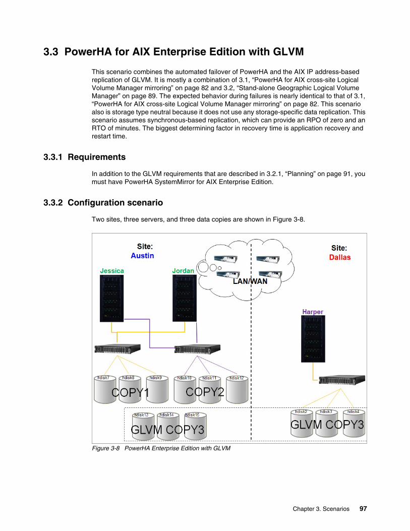
3.3 PowerHA for AIX Enterprise Edition with GLVM
This scenario combines the automated failover of PowerHA and the AIX IP address-based replication of GLVM. It is mostly a combination of 3.1, “PowerHA for AIX cross-site Logical Volume Manager mirroring” on page 82 and 3.2, “Stand-alone Geographic Logical Volume Manager” on page 89. The expected behavior during failures is nearly identical to that of 3.1, “PowerHA for AIX cross-site Logical Volume Manager mirroring” on page 82. This scenario also is storage type neutral because it does not use any storage-specific data replication. This scenario assumes synchronous-based replication, which can provide an RPO of zero and an RTO of minutes. The biggest determining factor in recovery time is application recovery and restart time.
3.3.1 Requirements
In addition to the GLVM requirements that are described in 3.2.1, “Planning” on page 91, you must have PowerHA SystemMirror for AIX Enterprise Edition.
3.3.2 Configuration scenario
Two sites, three servers, and three data copies are shown in Figure 3-8.
Figure 3-8 PowerHA Enterprise Edition with GLVM
Chapter 3. Scenarios 97
3.3.3 Failure scenario expectations
Here are the expected results based on each specific failure type:
� Application outage
PowerHA can monitor applications. In an application failure, PowerHA either can be restarted locally a specified number of times or failed over to the next node locally and then remotely.
� Storage loss
If there is lost storage access to any storage unit at either site, normal operations should continue because access to at least one complete copy is still available. In this scenario, any two of the three storage units can be lost and operations still continue. The disks most likely go into the missing state, and there are numerous reports of partitions going stale in the AIX error report.
� Server or LPAR
If a server or LPAR fails, for example, Jessica within the primary site in Austin, then a failover occurs to the next system, Jordan, within the site. Jordan takes over and activates all copies. All copies continue to be updated normally.
� Site outage
In a site outage where all storage and servers are unavailable in Austin, then a failover occurs to the Harper server in Dallas. The key difference is that only one copy of the data is available, and this scenario is where using the force varyon attribute for the resource group is needed so that the failover server starts the volume group with only one copy of data.
3.4 PowerHA for AIX Enterprise Edition with HyperSwap
The HyperSwap function in PowerHA SystemMirror for AIX Enterprise Edition 7.1.2 or later provides for continuous availability against storage errors. HyperSwap is based on storage-based synchronous replication. HyperSwap technology enables the host to transparently switch an applications I/O operation to the auxiliary volumes if physical connectivity exists between the host and the auxiliary storage subsystem.
The HyperSwap function in PowerHA SystemMirror supports the following capabilities within your environment:
� Eliminates primary disk subsystems as the single point of failure (SPOF).
� Provides maintenance for storage devices without any application downtime.
� Provides migration from an old storage device to a new storage system.
3.4.1 HyperSwap for PowerHA SystemMirror concepts
The HyperSwap function in PowerHA SystemMirror for AIX Enterprise Edition 7.1.2 or later enhances application availability for storage errors by using IBM DS8000 Metro Mirroring. If you use the HyperSwap function in your environment, your applications stay online even if errors occur on the primary storage because of application I/O to an auxiliary storage system.
98 High Availability and Disaster Recovery Options for IBM Power Cloud and On-Premises
The HyperSwap function uses a model of communication, which is called in-band, that sends the control commands to a storage system through the same communication channel as the I/O for the disk. The HyperSwap function supports the following types of configurations:
� Traditional Metro Mirror Peer-to-Peer Remote Copy (PPRC)
The primary volume group is visible only in the primary site, and the auxiliary volume group is visible only in the auxiliary site.
� HyperSwap
The primary and auxiliary volume groups are visible from the same node in the cluster.
You typically configure the HyperSwap function to be used in the following environments:
� Single-node environment
A single compute node is connected to two storage systems that are at two sites. This HyperSwap configuration is ideal to protect your environment against simple storage failures in your environment.
� Multiple-site environment
A cluster has multiple nodes that are spread across two sites. This HyperSwap configuration provides HADR for your environment.
Mirror groups in HyperSwap for PowerHA SystemMirror represent a container of disks and have the following characteristics:
� Mirror groups contain information about the disk pairs across the site. This information is used to configure mirroring between the sites.
� Mirror groups can contact a set of LVM volume groups and a set of raw disks that are not managed by the AIX OS.
� All the disk devices that are associated with the LVM volume groups and raw disks that are part of a mirror group are configured for consistency. For example, the IBM DS8800 system views a mirror group as one entity regarding consistency management during replication.
� The following types of mirror groups are supported:
– User mirror group
Represents the middleware-related disk devices. The HyperSwap function is prioritized internally by PowerHA SystemMirror and is considered low priority.
– System mirror group
Represents a critical set of disks for system operation, such as rootvg disks and paging space disks. These types of mirror groups are used for mirroring a copy of data that is not used by any other node or site other than the node that host these disks.
– Repository mirror group
Represents the cluster repository disks of that are used by CAA.
Chapter 3. Scenarios 99
3.4.2 Requirements
This section shows the hardware, software, and other requirements.
HardwareHere are the hardware requirements:
� An IBM POWER7 processor-based server or later (original support was POWER5 processor-based servers and later)
� A DS8800 system or later with firmware R6.3sp4 (86.xx.xx.x) or later
SoftwareHere are the software requirements:
� PowerHA 7.1.2 SP3 or later.
� AIX:
– Version 6, Release 1, Technology Level 8, Service Pack 2 or later
– Version 7, Release 1, Technology Level 2, Service Pack 2 or later
Other considerationsThere are a few more considerations to know about:
� Metro Mirror (in-band) functions, including HyperSwap, are supported in VIOS configurations by the N_Port ID Virtualization (NPIV) method of disk management.
� Metro Mirror (in-band) functions, including HyperSwap, are not supported by the virtual SCSI (VSCSI) method of disk management.
� To use Live Partition Mobility (LPM), you must bring the resource group that contains the mirror group into an unmanaged state by using the C-SPOC utility to stop cluster services with the Unmanage Resource Groups option. After you complete the LPM configuration process, you must bring the resource group back online by using SMIT. This process brings all mirror groups and resource groups back online.
� Disk replication relationships must adhere to a one-to-one relationship between the underlying logical subsystem (LSS). An LSS that is part of a mirror group cannot be part of another mirror group.
� Repository disks require that you specify an alternative disk or a disk that is not configured to use the HyperSwap function when you set HyperSwap property to Disable.
� SCSI reservations are not supported for devices that use the HyperSwap function.
� You must verify and synchronize the cluster when you change the cluster configuration. If you change the mirror group configuration while cluster services are active (Dynamic Automatic Reconfiguration Event (DARE)), those changes might be interpreted as failures, which result in unwanted cluster events. You must disable the HyperSwap function before you change any settings in an active cluster environment.
For more information about planning assistance, see Planning for HyperSwap for PowerHA SystemMirror.
100 High Availability and Disaster Recovery Options for IBM Power Cloud and On-Premises
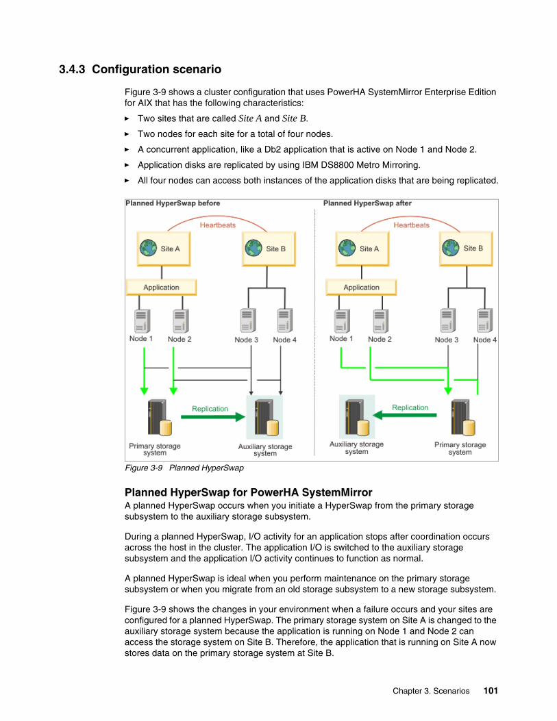
3.4.3 Configuration scenario
Figure 3-9 shows a cluster configuration that uses PowerHA SystemMirror Enterprise Edition for AIX that has the following characteristics:
� Two sites that are called Site A and Site B.
� Two nodes for each site for a total of four nodes.
� A concurrent application, like a Db2 application that is active on Node 1 and Node 2.
� Application disks are replicated by using IBM DS8800 Metro Mirroring.
� All four nodes can access both instances of the application disks that are being replicated.
Figure 3-9 Planned HyperSwap
Planned HyperSwap for PowerHA SystemMirrorA planned HyperSwap occurs when you initiate a HyperSwap from the primary storage subsystem to the auxiliary storage subsystem.
During a planned HyperSwap, I/O activity for an application stops after coordination occurs across the host in the cluster. The application I/O is switched to the auxiliary storage subsystem and the application I/O activity continues to function as normal.
A planned HyperSwap is ideal when you perform maintenance on the primary storage subsystem or when you migrate from an old storage subsystem to a new storage subsystem.
Figure 3-9 shows the changes in your environment when a failure occurs and your sites are configured for a planned HyperSwap. The primary storage system on Site A is changed to the auxiliary storage system because the application is running on Node 1 and Node 2 can access the storage system on Site B. Therefore, the application that is running on Site A now stores data on the primary storage system at Site B.
Chapter 3. Scenarios 101
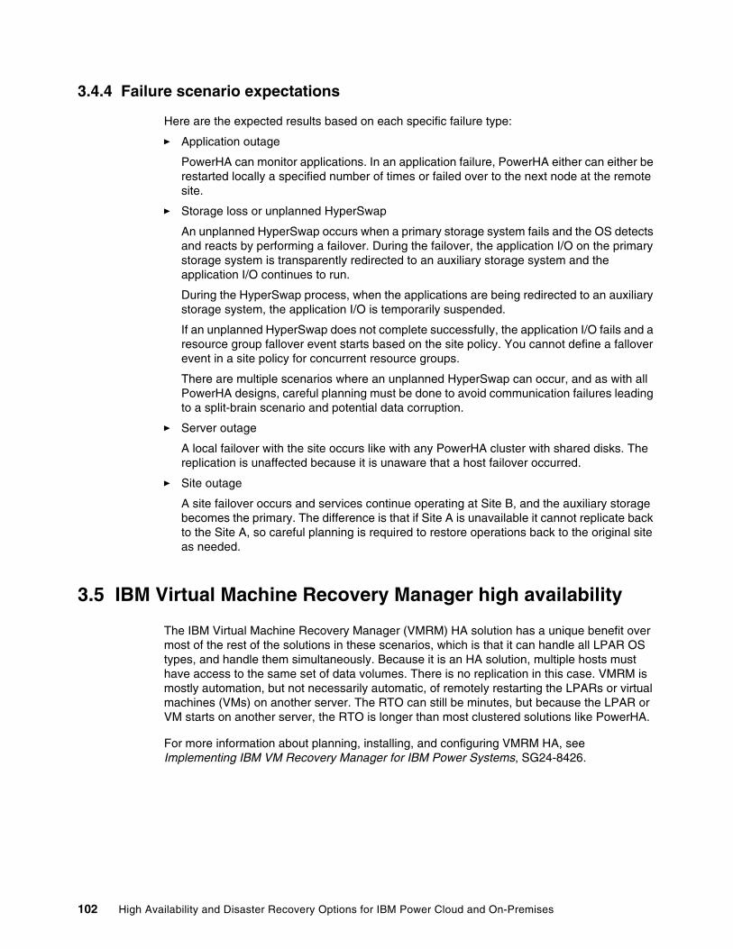
3.4.4 Failure scenario expectations
Here are the expected results based on each specific failure type:
� Application outage
PowerHA can monitor applications. In an application failure, PowerHA either can either be restarted locally a specified number of times or failed over to the next node at the remote site.
� Storage loss or unplanned HyperSwap
An unplanned HyperSwap occurs when a primary storage system fails and the OS detects and reacts by performing a failover. During the failover, the application I/O on the primary storage system is transparently redirected to an auxiliary storage system and the application I/O continues to run.
During the HyperSwap process, when the applications are being redirected to an auxiliary storage system, the application I/O is temporarily suspended.
If an unplanned HyperSwap does not complete successfully, the application I/O fails and a resource group fallover event starts based on the site policy. You cannot define a fallover event in a site policy for concurrent resource groups.
There are multiple scenarios where an unplanned HyperSwap can occur, and as with all PowerHA designs, careful planning must be done to avoid communication failures leading to a split-brain scenario and potential data corruption.
� Server outage
A local failover with the site occurs like with any PowerHA cluster with shared disks. The replication is unaffected because it is unaware that a host failover occurred.
� Site outage
A site failover occurs and services continue operating at Site B, and the auxiliary storage becomes the primary. The difference is that if Site A is unavailable it cannot replicate back to the Site A, so careful planning is required to restore operations back to the original site as needed.
3.5 IBM Virtual Machine Recovery Manager high availability
The IBM Virtual Machine Recovery Manager (VMRM) HA solution has a unique benefit over most of the rest of the solutions in these scenarios, which is that it can handle all LPAR OS types, and handle them simultaneously. Because it is an HA solution, multiple hosts must have access to the same set of data volumes. There is no replication in this case. VMRM is mostly automation, but not necessarily automatic, of remotely restarting the LPARs or virtual machines (VMs) on another server. The RTO can still be minutes, but because the LPAR or VM starts on another server, the RTO is longer than most clustered solutions like PowerHA.
For more information about planning, installing, and configuring VMRM HA, see Implementing IBM VM Recovery Manager for IBM Power Systems, SG24-8426.
102 High Availability and Disaster Recovery Options for IBM Power Cloud and On-Premises
3.5.1 Requirements
Here is the list of key requirements in addition to the licenses that are needed to use VMRM HA:
� An extra LPAR with at least a 1-core CPU and 8 GB memory running AIX 7.2 with Technology Level 2 Service Pack 1 (7200-02-01) or later for the controller system (KSYS). There must be 30 MB of disk space in the /opt directory and 200 MB of disk space in the /var directory.
� The HMCs must be Version 9 Release 9.1.0 or later.
� The pair of VIOSs per host must be Version 3.1.0.1 or later.
� LPM:
– All LPARs or VMs must have virtualized I/O resources.
– The same VLANs must be configured across hosts.
– SAN connectivity and zoning must be configured so that the target servers can access the host disks as required through VIOS.
� When using host groups, the KSYS subsystem requires two disks for health cluster management. A disk of at least 10 GB, which is called the repository disk, is required for health monitoring of the hosts, and another disk of at least 10 GB, which is called the HA disk, is required for health data tracking for each host group. All these disks must be accessible to all the VIOSs on each of the hosts on the host group.
� The LPARs or VMs must be at least one of the following OSs:
– AIX 6.1 or later.
– Red Hat Enterprise Linux (Little Endian) Version 7.4 or later (kernel version 3.10.0-693).
– SUSE Linux Enterprise Server (Little Endian) Version 12.3 or later (kernel version 4.4.126-94.22).
– Ubuntu Linux distribution Version 16.04.
– IBM i Version 7.2 or later.
Chapter 3. Scenarios 103
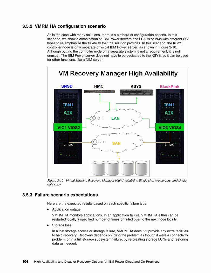
3.5.2 VMRM HA configuration scenario
As is the case with many solutions, there is a plethora of configuration options. In this scenario, we show a combination of IBM Power servers and LPARs or VMs with different OS types to re-emphasize the flexibility that the solution provides. In this scenario, the KSYS controller node is on a separate physical IBM Power server, as shown in Figure 3-10. Although putting the controller node on a separate system is not a requirement, it is not unusual. The IBM Power server does not have to be dedicated to the KSYS, so it can be used for other functions, like a NIM server.
Figure 3-10 Virtual Machine Recovery Manager High Availability: Single site, two servers, and single data copy
3.5.3 Failure scenario expectations
Here are the expected results based on each specific failure type:
� Application outage
VMRM HA monitors applications. In an application failure, VMRM HA either can be restarted locally a specified number of times or failed over to the next node locally.
� Storage loss
In a lost storage access or storage failure, VMRM HA does not provide any extra facilities to help recovery. Recovery depends on fixing the problem as though it were a connectivity problem, or in a full storage subsystem failure, by re-creating storage LUNs and restoring data as needed.
104 High Availability and Disaster Recovery Options for IBM Power Cloud and On-Premises
� Server or LPAR
If a server or LPAR fails, it can be restarted on the other server by using the KSYS controller node, so the KSYS controller node must be available to perform this action. This action can be either automatic or manually initiated.
� Site outage
In an entire site outage, this solution provides no additional recoverability because it is a single site without replication.
3.6 Virtual Machine Recovery Manager disaster recovery
The VMRM DR solution shares similar benefits of VMRM HA over many other solutions in DR scenarios: It can handle all LPAR OS types, and handle them simultaneously. Because VMRM DR is a DR solution, it is co-dependent on data replication across sites. VMRM DR is mostly automation, not necessarily automatic, of remotely restarting the LPARs or VMs on another server. The RPO varies based on the replication type, but the RTO can still be minutes. However, because the LPAR or VM starts on another server, the RPO is longer than most clustered solutions like PowerHA.
For more information about planning, installing, and configuring VMRM DR, see the following resources:
� IBM Geographically Dispersed Resiliency for IBM Power Systems, SG24-8382
� IBM VM Recovery Manager DR Version 1.5
3.6.1 Requirements
In addition to the requirements that are described in 3.5.1, “Requirements” on page 103, here are the requirements.
� An HMC at each site
� One of the supported storage replications:
– IBM Spectrum Virtualize:
• Metro Mirror• Global Mirror
– IBM DS8000 Global Mirror: DSCLI 7.7.51.48 or later
– IBM XIV and IBM FlashSystem A9000
– Dell EMC Symmetrix Remote Data Facility (SRDF) (VMAX):
• SRDF/S (Synchronous)• SRDF/A (Asynchronous)• SYMCLI installed on KSYS node
– Dell EMC Unity Storage System: Asynchronous replication with Version 5.0.6.0.6.252 or later
– Hitachi Virtual Storage Platform (VSP) G1000 and Hitachi VSP G400:
• CCI version 01-39-03/04 and model RAID-Manager or AIX• Synchronous data replication• Asynchronous data replication
Chapter 3. Scenarios 105
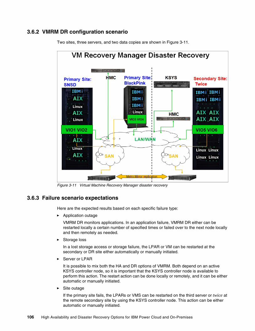
3.6.2 VMRM DR configuration scenario
Two sites, three servers, and two data copies are shown in Figure 3-11.
Figure 3-11 Virtual Machine Recovery Manager disaster recovery
3.6.3 Failure scenario expectations
Here are the expected results based on each specific failure type:
� Application outage
VMRM DR monitors applications. In an application failure, VMRM DR either can be restarted locally a certain number of specified times or failed over to the next node locally and then remotely as needed.
� Storage loss
In a lost storage access or storage failure, the LPAR or VM can be restarted at the secondary or DR site either automatically or manually initiated.
� Server or LPAR
It is possible to mix both the HA and DR options of VMRM. Both depend on an active KSYS controller node, so it is important that the KSYS controller node is available to perform this action. The restart action can be done locally or remotely, and it can be either automatic or manually initiated.
� Site outage
If the primary site fails, the LPARs or VMS can be restarted on the third server or twice at the remote secondary site by using the KSYS controller node. This action can be either automatic or manually initiated.
106 High Availability and Disaster Recovery Options for IBM Power Cloud and On-Premises
3.7 IBM Tivoli System Automation for Multiplatform
IBM Tivoli System Automation for Multiplatforms (TSA MP) automates IT resources by starting and stopping resources automatically and in the correct sequence. Resources are on a system that is referred to as node in the context of a cluster. Resources that are controlled by TSA MP can be applications, services, mounted disks, network addresses, or even data replication (basically, anything on a node that can be monitored, started, and stopped with commands or through an API). For each resource TSA MP provides, an availability state offers a way to start and stop them.
TSA MP allows customization of start and shutdown dependencies between resources and resource groups. After the resources are described in an automation policy, the operator can start or shut down an application in a reliable way.
The following section covers a three-node TSA MP cluster where a database or application server can fail over to a dedicated standby node.
3.7.1 Requirements
In addition to the TSA MP code itself, here are the requirements. TSA MP also provides a command, prereqSAM, to check whether all prerequisites are installed.
AIX prerequisitesThe following AIX prerequisites must be met:
� A 32-bit version of Java 7, Java 7.1, or Java 8 is required with the following minimum Service Refresh levels:
– Java 7.0 SR8: AIX package Java7.jre/Java7.sdk 7.0.0.145
– Java 7.1 SR2: AIX package Java71.jre/Java71.sdk 7.1.0.25
– Java 8.0 SR0: AIX package Java8.jre/Java8.sdk 8.0.0.507
– TSA MP Fix Pack Version 4.1.0.7 supports Java 8 SR6 FP30: AIX package Java8.jre/Java8.sdk 8.0.6.30
� TSA MP Fix Pack Version 4.1.0.7 on AIX. RSCT 3.2.6.1 will be installed. The following AIX TL levels are supported only with this fix pack:
– AIX 7.1 TL 5
– AIX 7.2 TL 3
– AIX 7.2 TL 4
– AIX 7.2 TL 5
� RSCT packages.
Linux prerequisitesThe following prerequisites must be met before TSA MP can be installed on a Linux system:
� RSCT packages.
� The perl-Sys-Syslog package is required on each Red Hat Enterprise Linux V7.1 system.
� The perl-Net-Ping package is required on each Red Hat Enterprise Linux V8 system.
� The mksh package is required on each SUSE Linux Enterprise Server (12/15) system.
Chapter 3. Scenarios 107
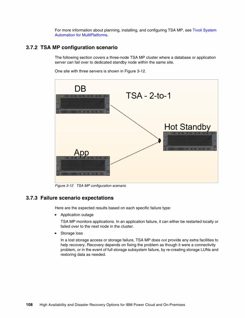
For more information about planning, installing, and configuring TSA MP, see Tivoli System Automation for MultiPlatforms.
3.7.2 TSA MP configuration scenario
The following section covers a three-node TSA MP cluster where a database or application server can fail over to dedicated standby node within the same site.
One site with three servers is shown in Figure 3-12.
Figure 3-12 TSA MP configuration scenario
3.7.3 Failure scenario expectations
Here are the expected results based on each specific failure type:
� Application outage
TSA MP monitors applications. In an application failure, it can either be restarted locally or failed over to the next node in the cluster.
� Storage loss
In a lost storage access or storage failure, TSA MP does not provide any extra facilities to help recovery. Recovery depends on fixing the problem as though it were a connectivity problem, or in the event of full storage subsystem failure, by re-creating storage LUNs and restoring data as needed.
108 High Availability and Disaster Recovery Options for IBM Power Cloud and On-Premises
� Server or LPAR
If a server or LPAR fails, it can be restarted on the other server by using the KSYS controller node, so the KSYS controller node must be available to perform this action, which can be either automatic or manually initiated.
� Site outage
In an entire site outage, this solution provides no extra recoverability because it is a single site without replication.
3.8 IBM Spectrum Scale stretched cluster
This section looks at the configuration of a stretched IBM Spectrum Scale cluster for DR. This solution is ideal if your application requires a HA, high-performance active-active file system across two data centers. Although the data centers can be connected by SAN or an IP network, we focus on the IP network solution because it is a solution for both on-premises and cloud.
IBM Spectrum Scale supports many applications:
� An HA and scalable Network File System (NFS)
� A tiered scalable storage solution
� A multi-site concurrent database solution
� A multi-media streaming solution
� A Persistent storage for Red Hat OpenShift or container solution
IBM Spectrum Scale has many advanced features, such as GPFS RAID, storage tiering, and information lifecycle management. For more information, see Overview of IBM Spectrum Scale.
This configuration uses two sites with IBM Spectrum Scale quorum nodes and a separate failure group that is defined at each site. A third site with a quorum node and a local disk with a file system descriptor is added for availability. IBM Spectrum Scale is installed on seven nodes, six of which provides cluster access to the data on their site’s SAN storage.
3.8.1 Configuration of the nodes and the Network Shared Disks
All sites in this example are connected by an IP network, which also provides client access to the clustered file system. At each of these sites, there are three nodes, one of which is a quorum node. Each of these nodes has SAN-attached local storage that provides the IBM Spectrum Scale Network Shared Disks (NSDs) (backing storage). The NSDs at SiteA are in failure group 1, and the NSDs at SiteB are in failure group 2. The third site has a quorum node with only one local NSD of type descOnly (contains no data) in failure group 3. The shared file system is built by using all these NSDs.
IBM Spectrum Scale uses failure groups to determine where to place copies of both file data and metadata. Thus, if a file system has the number of default data and metadata replicas set to 2, there is one copy of all data and metadata in each failure group. In this example, there is a complete mirror in both SiteA and SiteB.
Chapter 3. Scenarios 109
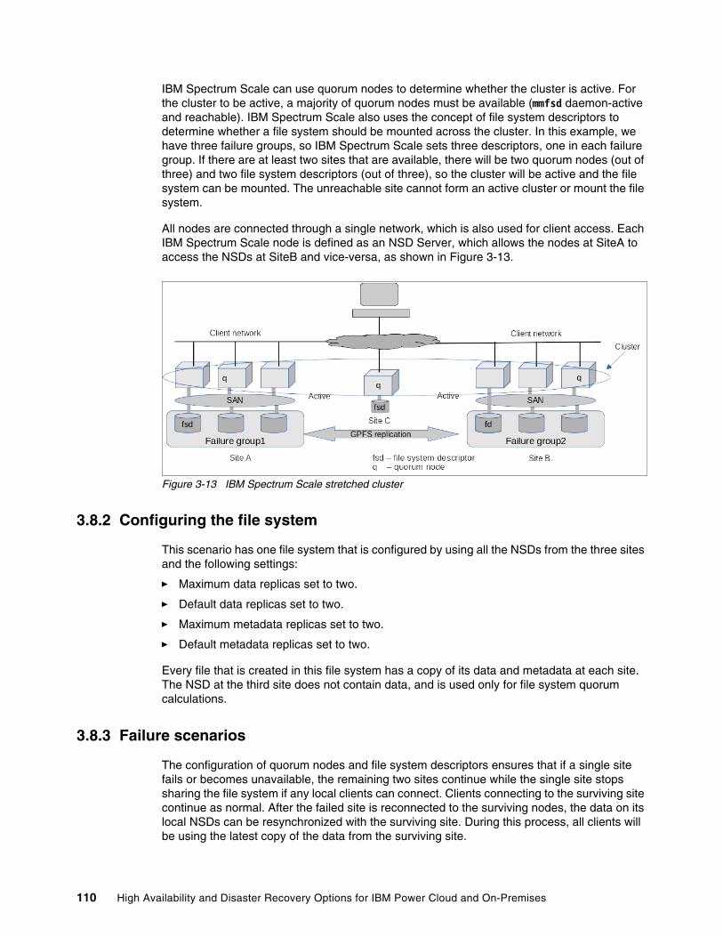
IBM Spectrum Scale can use quorum nodes to determine whether the cluster is active. For the cluster to be active, a majority of quorum nodes must be available (mmfsd daemon-active and reachable). IBM Spectrum Scale also uses the concept of file system descriptors to determine whether a file system should be mounted across the cluster. In this example, we have three failure groups, so IBM Spectrum Scale sets three descriptors, one in each failure group. If there are at least two sites that are available, there will be two quorum nodes (out of three) and two file system descriptors (out of three), so the cluster will be active and the file system can be mounted. The unreachable site cannot form an active cluster or mount the file system.
All nodes are connected through a single network, which is also used for client access. Each IBM Spectrum Scale node is defined as an NSD Server, which allows the nodes at SiteA to access the NSDs at SiteB and vice-versa, as shown in Figure 3-13.
Figure 3-13 IBM Spectrum Scale stretched cluster
3.8.2 Configuring the file system
This scenario has one file system that is configured by using all the NSDs from the three sites and the following settings:
� Maximum data replicas set to two.
� Default data replicas set to two.
� Maximum metadata replicas set to two.
� Default metadata replicas set to two.
Every file that is created in this file system has a copy of its data and metadata at each site. The NSD at the third site does not contain data, and is used only for file system quorum calculations.
3.8.3 Failure scenarios
The configuration of quorum nodes and file system descriptors ensures that if a single site fails or becomes unavailable, the remaining two sites continue while the single site stops sharing the file system if any local clients can connect. Clients connecting to the surviving site continue as normal. After the failed site is reconnected to the surviving nodes, the data on its local NSDs can be resynchronized with the surviving site. During this process, all clients will be using the latest copy of the data from the surviving site.
110 High Availability and Disaster Recovery Options for IBM Power Cloud and On-Premises
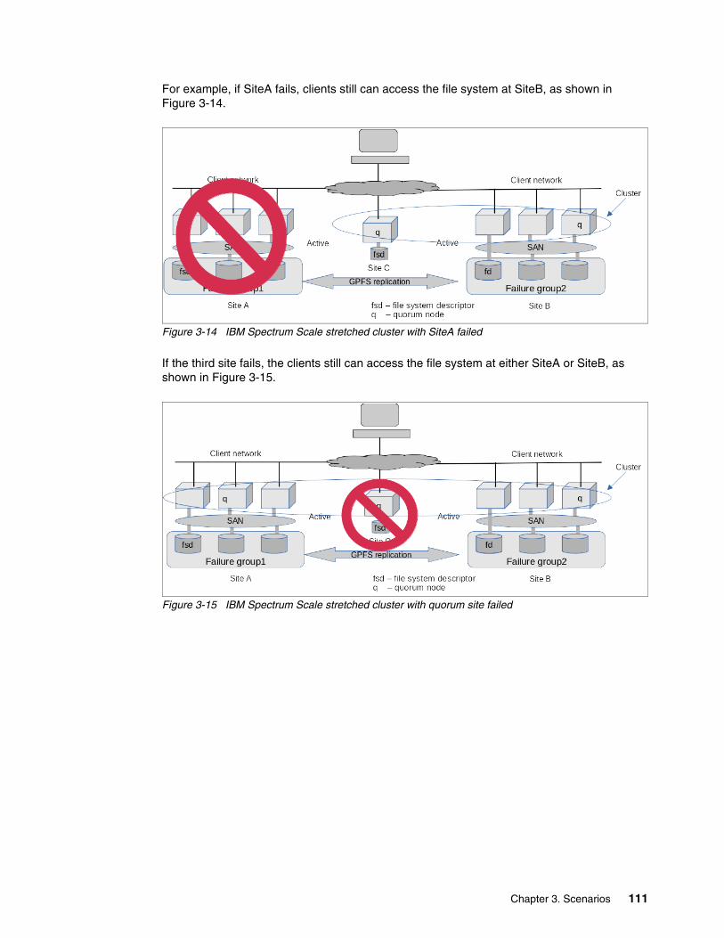
For example, if SiteA fails, clients still can access the file system at SiteB, as shown in Figure 3-14.
Figure 3-14 IBM Spectrum Scale stretched cluster with SiteA failed
If the third site fails, the clients still can access the file system at either SiteA or SiteB, as shown in Figure 3-15.
Figure 3-15 IBM Spectrum Scale stretched cluster with quorum site failed
Chapter 3. Scenarios 111

112 High Availability and Disaster Recovery Options for IBM Power Cloud and On-Premises
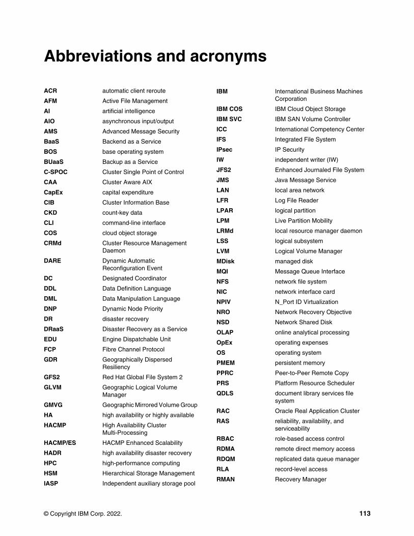
ronyms
ACR automatic client reroute
AFM Active File Management
AI artificial intelligence
AIO asynchronous input/output
AMS Advanced Message Security
BaaS Backend as a Service
BOS base operating system
BUaaS Backup as a Service
C-SPOC Cluster Single Point of Control
CAA Cluster Aware AIX
CapEx capital expenditure
CIB Cluster Information Base
CKD count-key data
CLI command-line interface
COS cloud object storage
CRMd Cluster Resource Management Daemon
DARE Dynamic Automatic Reconfiguration Event
DC Designated Coordinator
DDL Data Definition Language
DML Data Manipulation Language
DNP Dynamic Node Priority
DR disaster recovery
DRaaS Disaster Recovery as a Service
EDU Engine Dispatchable Unit
FCP Fibre Channel Protocol
GDR Geographically Dispersed Resiliency
GFS2 Red Hat Global File System 2
GLVM Geographic Logical Volume Manager
GMVG Geographic Mirrored Volume Group
HA high availability or highly available
HACMP High Availability Cluster Multi-Processing
HACMP/ES HACMP Enhanced Scalability
HADR high availability disaster recovery
HPC high-performance computing
HSM Hierarchical Storage Management
IASP Independent auxiliary storage pool
Abbreviations and ac
© Copyright IBM Corp. 2022.
IBM International Business Machines Corporation
IBM COS IBM Cloud Object Storage
IBM SVC IBM SAN Volume Controller
ICC International Competency Center
IFS Integrated File System
IPsec IP Security
IW independent writer (IW)
JFS2 Enhanced Journaled File System
JMS Java Message Service
LAN local area network
LFR Log File Reader
LPAR logical partition
LPM Live Partition Mobility
LRMd local resource manager daemon
LSS logical subsystem
LVM Logical Volume Manager
MDisk managed disk
MQI Message Queue Interface
NFS network file system
NIC network interface card
NPIV N_Port ID Virtualization
NRO Network Recovery Objective
NSD Network Shared Disk
OLAP online analytical processing
OpEx operating expenses
OS operating system
PMEM persistent memory
PPRC Peer-to-Peer Remote Copy
PRS Platform Resource Scheduler
QDLS document library services file system
RAC Oracle Real Application Cluster
RAS reliability, availability, and serviceability
RBAC role-based access control
RDMA remote direct memory access
RDQM replicated data queue manager
RLA record-level access
RMAN Recovery Manager
113
ROHA Resource Optimized High Availability
RPO recovery point objective
RPV Remote Physical Volume
RTO recovery time objective
SaaS software as a service
SAN storage area network
SDS software-defined storage
SEA Shared Ethernet Adapter
SLA service-level agreement
SLIC System Licensed Internal Code
SOA service-oriented architecture
SPOF single point of failure
SRDF Symmetrix Remote Data Facility
SRE Site Reliability Engineering
SRR Simplified Remote Restart
SRS Simulated Role Swap
SSR Segment-by-Segment Routing
STONITH Shoot the Other Node in the Head
SW single writer
TCT Transparent Cloud Tiering
TSA MP IBM Tivoli System Automation for Multiplatforms
TSO Time Sharing Option
VIOS Virtual I/O Server
VM virtual machine
VMRM Virtual Machine Recovery Manager
VPMEM virtual persistent memory
VSCSI virtual SCSI
VSP Virtual Storage Platform
WAN wide area network
WLB workload balancing
WPAR workload partition
114 High Availability and Disaster Recovery Options for IBM Power Cloud and On-Premises
Related publications
The publications that are listed in this section are considered suitable for a more detailed description of the topics that are covered in this paper.
IBM Redbooks
The following IBM Redbooks publications provide more information about the topics in this document. Some publications that are referenced in this list might be available in softcopy only.
� Achieving Hybrid Cloud Cyber Resiliency with IBM Spectrum Virtualize for Public Cloud, REDP-5585.
� End-to-end Automation with IBM Tivoli System Automation for Multiplatforms, SG24-7117.
� Exploiting IBM AIX Workload Partitions, SG24-7955.
� High Availability and Disaster Recovery Planning: Next-Generation Solutions for Multiserver IBM Power Systems Environments, REDP-4669.
� IBM AIX Continuous Availability Features, REDP-4367.
� IBM Copy Services Manager Implementation Guide, SG24-8375.
� IBM DS8000 Copy Services: Updated for IBM DS8000 Release 9.1, SG24-8367.
� IBM PowerHA SystemMirror for AIX Cookbook, SG24-7739.
� IBM Power System E980: Technical Overview and Introduction, REDP-5510.
� IBM SAN Volume Controller Stretched Cluster with PowerVM and PowerHA, SG24-8142.
� IBM Spectrum Virtualize 3-Site Replication, SG24-8504.
� IBM Spectrum Virtualize HyperSwap SAN Implementation and Design Best Practices, REDP-5597.
� IBM Storwize V7000, Spectrum Virtualize, HyperSwap, and VMware Implementation, SG24-8317.
� Implementing High Availability and Disaster Recovery Solutions with SAP HANA on IBM Power Systems, REDP-5443.
� Implementing IBM Spectrum Virtualize for Public Cloud Version 8.3.1, REDP-5602.
� Implementing the IBM System Storage SAN Volume Controller with IBM Spectrum Virtualize Version 8.4, SG24-8491.
� Implementing IBM VM Recovery Manager for IBM Power Systems, SG24-8426.
� Introduction to Workload Partition Management in IBM AIX Version 6.1, SG24-7431.
� Multicloud Solution for Business Continuity using IBM Spectrum Virtualize for Public Cloud on AWS Version 1 Release 1, REDP-5545.
� PowerHA SystemMirror for IBM i Cookbook, SG24-7994.
© Copyright IBM Corp. 2022. 115
You can search for, view, download, or order these documents and other Redbooks, Redpapers, web docs, drafts, and additional materials, at the following website:
ibm.com/redbooks
Online resources
These websites are also relevant as further information sources:
� Demonstration of automated remote restart capability:
https://www.youtube.com/watch?v=6s72ZR5OLr8
� Demonstration of Virtual Machine Recovery Manager (VMRM) DR:
https://www.youtube.com/watch?v=kTe0Tzp0ghs&t=8s
� IBM Copy Services base publications:
https://www.ibm.com/docs/en/csm
� IBM Spectrum Virtualize for Public Cloud:
https://www.ibm.com/products/spectrum-virtualize-for-public-cloud
� IBM Tivoli System Automation for Multiplatforms:
https://www.ibm.com/docs/en/tsafm/4.1.0
Help from IBM
IBM Support and downloads
ibm.com/support
IBM Global Services
ibm.com/services
116 High Availability and Disaster Recovery Options for IBM Power Cloud and On-Premises

ibm.com/redbooks
Printed in U.S.A.
Back cover
ISBN 0738460362
REDP-5656-00
®