floorplanning-aware design space exploration for application-specific hierarchical networks on-chip
TRANSCRIPT

Floorplanning-Aware Design Space Exploration forApplication-Specific Hierarchical Networks on-Chip
Debora Matos1 Gianluca Palermo2 Vittorio Zaccaria2 Cezar Reinbrecht1
Altamiro Susin1 Cristina Silvano2 Luigi Carro1
1UFRGS Institute of Informatics, Porto Alegre, Brazil{debora.matos, cezar.reinbrecht, carro, susin}@inf.ufrgs.br
2Politecnico di Milano - Dipartimento di Elettronica e Informazione, Milano, Italy{gpalermo, silvano, zaccaria}@elet.polimi.it
ABSTRACT
Application-specific network-centric architectures (such as Networkson-Chip, NoCs) have recently become an effective solution to sup-port high bandwidth communication in Multiprocessor Systems-on-Chip (MPSoCs). Moreover, the introduction of the hierarchyconcept in the NoC design benefits from the main locality nature ofthe communication in MPSoC architectures. This paper presentsa methodology to design Application Specific Hierarchical NoC(ASHiNoC) architectures considering foorplanning information. Thepresented approach targets heterogeneous clustered architectureswhere the intra-cluster communication is managed by a low-latencycircuit-switched crossbar, while the inter-cluster communicationsare managed by a high-bandwidth packet-based NoC, allowing reg-ulars topologies. The proposed design flow faces the problem bystarting from the cluster selection down-to the foorplanning-awareestimation of the interconnect performances in terms of latency,power, area within each cluster and for the backbone NoC. Exper-imental results show that the AHiNoC architecture is able to guar-antee an interconnection power and latency reduction of 49% and33% respectively, at a cost of an area increment of 78% with respectto a flat topology version. 1
Categories and Subject Descriptors
B.7.1 [Hardware]: Integrated Circuits—VLSI (very large scale in-tegration); C.0 [General]: System architectures; C.4 [Performanceof Systems]: Design Studies, Modeling Techniques
1. INTRODUCTIONThe current trend in System-on-Chip (SoC) design is to integrate
a large number of processors, memories and hardware accelera-tors onto a single die, making real the concept of MultiProcessorSystem-on-chip. The new philosophy brought by the enormousdegree of integration raises also new challenges in designing in-terconnection infrastructure, since old communication paradigmscannot scale anymore. Due to the complexity of future MPSoC
1This work was supported in part by the EC under grant COM-PLEX, 2PARMA, SMECY and HIPEAC2-NoE
Permission to make digital or hard copies of all or part of this work forpersonal or classroom use is granted without fee provided that copies arenot made or distributed for profit or commercial advantage and that copiesbear this notice and the full citation on the first page. To copy otherwise, torepublish, to post on servers or to redistribute to lists, requires prior specificpermission and/or a fee.NoCArc ’11, December 4, 2011, Porto Alegre, BrazilCopyright 2011 ACM 978-1-4503-0947-9 ...$10.00.
designs, the systems are requiring other alternatives to interconnectprocessing elements (PEs) instead of large and somehow inefficientconventional networks-on-chips (NoCs).
The performance and energy dissipation of a system is totallydependent on the network topology and how the cores are con-nected in the NoC. Selecting the network topology is one of thefirst steps in designing such kind of complex interconnection, sincethe routing strategy, flow control methods and mapping cores onthe network nodes heavily depend on the topology [1].
The use of regular Network-on-Chip topology, such as thoseused in macro-networks (e.g. mesh, torus, ring), represents a pri-ori decision especially when either we are targeting to homoge-neous systems or the system design characteristics (type and sizeof cores and traffic patterns) are not completely well known at thebeginning of the design phase. In fact, regular NoC topologies en-able design predictability, controlling the wires delay that some-times is enough to satisfy general-purpose requirements. However,higher performance and/or lower power dissipation are not possi-ble from the general alternatives since regular topologies presentpoor performance and have a large power overhead [2], [3]. Be-sides, a general purpose solution is not a good solution in the em-bedded system context where communication patterns are irregularand strongly application-dependent, while the cores are completelyheterogeneous also in terms of size impacting the links length andconsequently the network latency and its maximum frequency [3,4, 5, 6].
In the context of application-specific NoC design, both the knowl-edge of communication patterns and core dimension should be ex-ploited for optimization purposes, avoiding the design for either theworst case or average case which respectively means either waste ofarea or possible communication bottleneck. In fact, the knowledgeof the communication patterns helps on finding the best core allo-cations reducing the number of intermediate network hop for highbandwidth edges, and consequently reducing the network powerand latency. On the other side, the core size knowledge can beused to customize the topology considering that not all the router-to-router links can have the same size and that small cores can beconnected also to the same router instead of having one router percore.
Analyzing the interconnect architectures, one possibility in orderto obtain higher performance would be to use a circuit-switchingsolution employing crossbar switches in the interconnection. In or-der to circumvent the scalability problems of this component, theusage of a hierarchical topology using crossbar switches for localcommunication and packet-switched routers for the global commu-nication seems to be a viable solutions.
In this paper is presented the ASHiNoC (Application Specific Hi-erarchical NoC) analyzer framework, allowing an optimized topol-ogy for such kind of specific-application hierarchical interconnec-tion. The main contributions of this paper are:
31

• The exploitation of a hierarchical interconnection where thelocal interconnections are made by circuit-switched cross-bars while the global interconnection uses a packet-switchednetwork;
• The introduction of an automatic Design Space Exploration(DSE) framework for designing hierarchical network topolo-gies based on floorplanning considerations;
• The application-specific optimization in terms of area, powerand latency of the hierarchical interconnection infrastructure,while maintaining communication requirements, consideringboth core mapping and clustering problems and architecturalparameters tuning.
Experimental results present the power/performance/area trade-offs solutions for the Application-Specific Hierarchical NoC, bychanging mapping and architectural parameters on a state of the artreal application.
The paper is organized as follows. Section 2 briefly introducesthe background and state-of-the-art, while the hierarchical NoC ar-chitecture - ASHiNoC is presented in Section 3. The methodologyis proposed in Section 4 where we detail the flow used to find anoptimal hierarchical topology. In section 5 are shown the resultsobtained from the proposed tool and finally Section 6 concludesthe paper.
2. PREVIOUS WORKSA wide range of works have been proposed in literature to presents
tools and methodology to efficiently design application-specific NoCtopology, such as [5, 3, 4, 6, 7, 2].
In [5] the authors proposed four different approaches for application-specific mapping and topology customization applied to STNoCarchitecture. The proposed methods were based on the orthogonal-ization of the mapping an topology design concepts. The topolo-gies are derived from ring and spidergon topologies and this pro-posal considers routers with only three input/output ports for theconnection among the NoC routers and one port to connect thecore. However, the topology exploration in this work is limitedsince the proposal concerns only to the STNoC architecture.
In [3] was presented a method to considers in the floorplan thewiring complexity for NoC topology synthesis process. The pro-posed mechanism integrates the synthesis, generation, simulationand physical design processes. Firstly the tool considers a set ofconstrains defined by user. In the next step the NoC architecture issynthesized and a topology that best approximates to design con-straints is chosen, ensuring the required bandwidth for the appli-cation. After obtaining the synthesized topology, the floorplanninginformation are extracted. For the cluster partition the authors usedthe min-cut strategy to group the cores. The connection amongclusters was made using a path allocation algorithm.
Chan and Parameswaran presented in [4] an iterative methodol-ogy to obtain an energy efficient topology supporting point-to-pointand packet-switched connections. This work considers the effectsof the wire length according to the topology. The topology genera-tion algorithm consists of two phases: a phase that uses a topologyas an initial starting point and a refinement phase where are an-alyzed the possibilities to add or remove the links to compose apoint-to-point or a router connection.
Another proposal for an application-specific network-on-chip ar-chitecture was presented in [6]. This work proposed two heuristicalgorithms to examine the partition possibilities for communica-tion flows. The first algorithm was called CLUSTER and it reducesthe number of set partitions from a smaller subset of set partitions.The second algorithm was called DECOMPOSE and in this caseit starts with single cluster and creates new partitions for each it-eration. The two approaches generate the network topology using
a Rectilinear-Steiner-Tree based algorithm to evaluate the costs ofeach partitioned group.
In [7] floorplan-aware method focusing to minimize the powerconsumption was presented. The authors use a partition drivenfloorplanning to obtain the physical information. The switchesand network interfaces are defined using heuristic method and amin-cost max-flow algorithm, respectively. The difference of thisproposal is that it considers the network interfaces in the topol-ogy generation. The alternative to minimize power consumptionis achieved using an incremental path allocation. Another simi-lar proposal is found in [2]. This work attacks the same problembut uses a genetic algorithm to synthesize application-specific NoCtopology. However the majority of these proposals considers clus-ter connected by switches with buffers and many other controls thatincrease the area and power dissipation.
Despite of the previous works present advantages due to theapplication-specific NoC customization, their approaches continueto be within the concept of a flat topology. In fact, the idea of coreclustering is not used to separate local and global communicationsdefining two levels of interconnections, but it is used mainly to re-duce the number of NoC nodes, increasing the number of ports foreach router.
In this paper we present an automatic application-specific frame-work to exploit hierarchical interconnection based on floorplanninginformation, considering together the cores clustering, NoC map-ping and interconnection synthesis problems.
3. TARGET NOC ARCHITECTUREA hierarchical NoC topology brings many advantages for com-
plex MPSoCs since it can exploit the communication locality of thesystem, while maintaining the NoC advantages. Besides, the hier-archical NoC topology has proved not only to reduce the number ofhops when compared to a regular packet-switched topology, but itis also able to provide a suitable bandwidth, power and QoS results.
In this context, the target Application-Specific Hierarchical Net-work on-Chip (ASHiNoC) is composed by small clusters inter-connected by local crossbars (LXBars), that drastically reduce thepower consumption and improves the communication performanceof the system, interconnected by a regular packet switched back-bone NoC (BNoC). Figure 1 shows an example of the target ASHiNoCtopology.
Figure 1: Example of the target hierarchical NoC
LXBars. The proposed hierarchical network is constituted bycrossbar switches in the local level. Crossbar switches architec-tures are simple and provide fast communication among the cores.Besides, cores with more communication minimize the communi-cation energy when are in the same cluster [7].
32

The clusters are composed by the crossbar and an arbiter usedto define the multiplexer selection for each output data. This ar-biter is based in the Round-Robin algorithm and in the designedcluster architecture the data are only sent for the destination core ifthe destination core is available to receive it. In such case, up to ncommunications can be made simultaneous, where n is the numberof cores presents in the cluster. Each core sends a signal control in-forming its availability and a handshake protocol is used to managethe receiving data. The data is transmitted in accordance with thiscontrol and with the request of the source core (req, that containsthe ID of the destination core). The sending of messages uses aprotocol indicating the end-of-message (eom). The arbiter is com-posed by a finite state machine (FSM) that controls the requests fora same port and each output port has an arbiter. The implementationof the Round Robin algorithm takes only two cycles independentlyof the crossbar switch size, eventually impacting the LXBar maxi-mum frequency. In the first cycle, the arbiter verifies all requisitionsof the input ports of a crossbar for an output port and in the secondcycle it attends the next requisition. In summary, the arbiter verifiesonly the input ports where the requisitions are activated and in anorderly manner it defines the next input port that must be attended,ensuring the starvation free.
BNoC. For the global level we decided to use a conventionalpacket switching routers with a wormhole mechanism. This strat-egy has been the most popular since it is simple, regular and presentssuitable features for this level of hierarchy. The BNoC router issimilar to a conventional NoC, but in this case, instead of a PE be-ing coupled to a local channel, the local channel has a connectionwith a cluster port. However in the global level different regulartopologies can be considered like mesh, ring, torus, spidergon andothers. Anyway, for an application-specific NoC, only communi-cations with low bandwidth are defined in the global level.
The architecture of the crossbar switches and routers is illus-trated in figure 2. The bridge modules are the boundaries betweenthe two network levels and integrate the synchronization logic whenthe LXBars and the BNoC work at different frequencies.
Figure 2: LXBar switch and BNoC router architecture whichconstitute the basis of the target ASHiNoC Architecture
4. THE PROPOSED METHODOLOGYThe advantage introduced by the usage of hierarchical intercon-
nection topology for heterogeneous systems can only be exploitedby automatic tools for the design space exploration during the NoCsynthesis. In fact, the large design space introduced by the mappingand clustering decisions together with BNoC and LXBars architec-ture configuration is not possible to be faced manually.
The Application-Specific network-on-chip synthesis that we arefacing is carried out by selecting the NoC parameters (such as fre-quency and router buffer depth), the topology and by mapping the
Figure 3: ASHiNoC analyzer framework
application cores into the network nodes (Core-to-node mapping).In particular for the target Hierarchical NoC, the synthesis consistsalso in the generation of the local Xbar-based cluster interconnec-tions. The synthesis step is performed by taking into account es-timated performance, power consumption and latency consideringfloorplanning information.
4.1 Problem FormulationTo define the problem of designing an Application Specific Hi-
erarchical NoC, let us introduce the following concepts: the Coregraph, used to describe the target application, and the NoC topol-ogy graph, used in our approach to describe the Backbone NoCand the Core-to-Node mapping function used to correlate the twoprevious graphs.
The Core Graph is a directed graph G(V, E) where V is the setof PEs belonging to the target System-on-chip and E is the set ofedges representing the communication between the IPs vi ∈ V andvj ∈ V . The weight of the edge ei,j ∈ E, denoted by commi,j ,represents the bandwidth of the directed communication from vi tovj .
The NoC Topology Graph is a directed graph P(U, F ) whereU is the set of network nodes and F is the set of directed edges(ui,uj) representing an existing link between the network nodesui ∈ U and uj ∈ U . Each edge fi,j ∈ F has a weight bwi,j whichrepresents the bandwidth available across fi,j .
The Core-to-Node mapping function M : V → U is definedas the set Core-to-Node mappings (vi, uj), representing the Corevi ∈ V mapped to the network node uj ∈ U . The set of possiblemappings M(P,G) depends on a given network topology graph P
and an Core graph G.Despite of neither the NoC Topology Graph nor the Core-to-
Node mapping function explicitly manage the cluster hierarchy, weare able to manage the hierarchy in the mapping problem formu-lation considering that two (or more) cores mapped into the samenetwork node are parts of the same cluster and so interconnectedby a crossbar-based interconnection. Moreover, to evaluate the per-formance of each mapping and of the related Application-SpecificHierarchical NoC including the floorplanning information, in ourproblem we considered an enhanced version of the Core Graphwhere each core has been annotated with the equivalent area andaspect-ratio.
4.2 Overview of the application specific method-ology
The tool flow proposed in this paper is shown in Figure 3. It takesas input the definition of the target topology in terms of number ofrouters and pattern (e.g. mesh, ring), the routing functions associ-ated to the topology and the enhanced version of the Core Graph
33
(annotated also with the core dimensions) and generates as outputthe best ASHiNoC architecture together with the power/area/latencyevaluations. It is composed of 5 main steps done iteratively: coreallocation, floorplanning, cluster estimation, backbone NoC esti-mation and hierarchical NoC estimation.
Core Allocation. This is the step that has in charge the clustergeneration, each core of the Core Graph G(V, E) is mapped on aspecific cluster. It has been implemented by using the NSGA-II [8]multiobjective genetic algorithm since the design space of the tar-get problem results to be too vast to be analyzed exhaustively. Theadopted chromosome structure is composed by a set of genes equalto the number of cores in the Core Graph. Each gene identifiesthe cluster where the related core has been mapped. This chro-mosome structure gives the possibility to be extended by encodingalso additional genes for other architectural parameters related tothe Hierarchical NoC (e.g. Data-path width, BNoC frequency).
Floorplanning. This step analyzes the core-to-cluster assign-ment, performing the floorplan estimation for each cluster and forthe backbone NoC. The floorplan has been derived by using theHotfloorplan tool [9] considering a two dimensional layout, whereeach core is represented by a rectangular region with size and aspect-ratio specified in the input Core Graph, and each local crossbar andbackbone router (together with its related Network Interface) arerepresented by a square with size dependent respectively on thenumber of cores connected and on the BNoC topology 2. The cre-ated floorplan is based on the topology of the entire hierarchicalnetwork, by minimizing a linear combination of the silicon areafor the entire floorplan and the distance between interconnected re-sources.
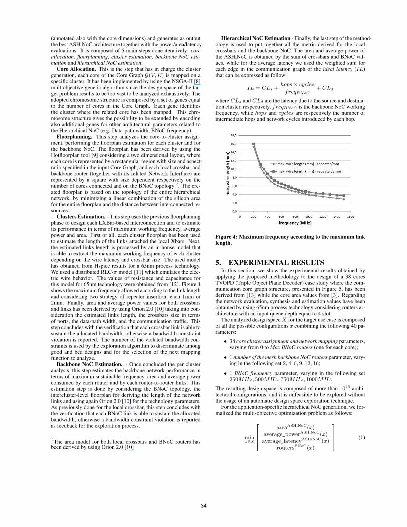
Clusters Estimation. - This step uses the previous floorplanningphase to design each LXBar-based interconnection and to estimateits performance in terms of maximum working frequency, averagepower and area. First of all, each cluster floorplan has been usedto estimate the length of the links attached the local Xbars. Next,the estimated links length is processed by an in house model thatis able to extract the maximum working frequency of each clusterdepending on the wire latency and crossbar size. The used modelhas obtained from Hspice results for a 65nm process technology.We used a distributed RLC-π model [11] which emulates the elec-tric wire behavior. The values of resistance and capacitance forthis model for 65nm technology were obtained from [12]. Figure 4shows the maximum frequency allowed according to the link lengthand considering two strategy of repeater insertion, each 1mm or2mm. Finally, area and average power values for both crossbarsand links has been derived by using Orion 2.0 [10] taking into con-sideration the estimated links length, the crossbars size in termsof ports, the data-path width, and the communication traffic. Thisstep concludes with the verification that each crossbar link is able tosustain the allocated bandwidth, otherwise a bandwidth constraintviolation is reported. The number of the violated bandwidth con-straints is used by the exploration algorithm to discriminate amonggood and bed designs and for the selection of the next mappingfunction to analyze.
Backbone NoC Estimation. - Once concluded the per clusteranalysis, this step estimates the backbone network performance interms of maximum sustainable frequency, area and average powerconsumed by each router and by each router-to-router links. Thisestimation step is done by considering the BNoC topology, theintercluster-level floorplan for deriving the length of the networklinks and using again Orion 2.0 [10] for the technology parameters.As previously done for the local crossbar, this step concludes withthe verification that each BNoC link is able to sustain the allocatedbandwidth, otherwise a bandwidth constraint violation is reportedas feedback for the exploration process.
2The area model for both local crossbars and BNoC routers hasbeen derived by using Orion 2.0 [10]
Hierarchical NoC Estimation - Finally, the last step of the method-ology is used to put together all the metric derived for the localcrossbars and the backbone NoC. The area and average power ofthe ASHiNoC is obtained by the sum of crossbars and BNoC val-ues, while for the average latency we used the weighted sum foreach edge in the communication graph of the ideal latency (IL)that can be expressed as follow:
IL = CLs +hops × cycles
freqBNoC
+ CLd
where CLs and CLd are the latency due to the source and destina-tion cluster, respectively, freqBNoC is the backbone NoC workingfrequency, while hops and cycles are respectively the number ofintermediate hops and network cycles introduced by each hop.
Figure 4: Maximum frequency according to the maximum linklength.
5. EXPERIMENTAL RESULTSIn this section, we show the experimental results obtained by
applying the proposed methodology to the design of a 38 coresTVOPD (Triple Object Plane Decoder) case study where the com-munication core graph structure, presented in Figure 5, has beenderived from [13] while the core area values from [3]. Regardingthe network evaluation, synthesis and estimation values have beenobtained by using 65nm process technology considering routers ar-chitecture with an input queue depth equal to 4 slot.
The analyzed design space X for the target use case is composedof all the possible configurations x combining the following 40 pa-rameters:
• 38 core cluster assignment and network mapping parameters,varying from 0 to Max BNoC routers (one for each core);
• 1 number of the mesh backbone NoC routers parameter, vary-ing in the following set 2, 4, 6, 9, 12, 16;
• 1 BNoC frequency parameter, varying in the following set250MHz, 500MHz, 750MHz, 1000MHz
The resulting design space is composed of more than 1046 archi-tectural configurations, and it is unfeasible to be explored withoutthe usage of an automatic design space exploration technique.
For the application-specific hierarchical NoC generation, we for-malized the multi-objective optimization problem as follows:
minx∈X
2
6
6
4
areaASHiNoC(x)average_powerASHiNoC(x)average_latencyASHiNoC(x)
routersBNoC(x)
3
7
7
5
(1)
34

Figure 5: Communication Core Graph for the TVOPD bench-mark
and subject to the respect of the application communication band-width.
In particular, the minimization problem we faced for this use caseconsists of four objective functions. Three of the objective func-tions are related to the entire ASHiNoC interconnection: the area,the average power consumption and the average latency. The fourthrefers to the Backbone NoC component of the ASHiNoC intercon-nection and in particular to the number of routers. The minimiza-tion problem is without any constraint except that to support theQoS requirements of the TVOPD application, the resulting designconfigurations should be able to support the data traffic presentedin Figure 5.
To help the system architect to select among the large numberof feasible solutions composing the Pareto front, and to better an-alyze the impact of the hierarchy in the different design configu-rations, we decided to first cluster the Pareto solution with respectto the number of routers in the Backbone NoC and then selectsa champion solution for each cluster by using a decision-making-mechanism based on the following product:
area(x) × avg_power(x) × avg_latency(x) (2)
The results of the NSGA-II based exploration phase after 50Kevaluations can be found in Figure 6, where we plot the intercon-nection Average Power and Area (respectively in Figure 6(a) and6(b)) and the Average Latency and BNoC hops for the best config-urations found accordingly to Equation 2 by varying the number ofrouters (see Figure 6(c)). Before commenting the results we wantto underline that, despite of the global trends will be clear in Figure6, some unexpected local trends can be shown due to the DecisionMaking Mechanism (DMM) represented by Equation 2.
Figure 6(a) shows the ASHiNoC average power, split also theXbars and Backbone NoC components. Except for a small reduc-tion passing from 4 to 9, the global power trend is to increase withthe number of BNoC nodes. While the backbone NoC power com-ponent, which is the main responsible of the global trend, increaseswith the number of nodes, the opposite happens for the Xbar com-
(a) Average Power
(b) Area
(c) Average Latency
Figure 6: ASHiNoC interconnection (a) Average Power, (b)Area and (c) Average Latency for the best configuration foundwith the proposed methodology, by varying the number of therouters in the backbone mesh NoC
ponent. This is mainly due to the increment of data traffic thatpass from inter-cluster to intracluster communications, removingthe pressure from the local Xbars. Passing from 4 to 9 BNoC nodes(probably due to the Equation 2 based selection), an almost con-stant BNoC power together with a power reduction due to Xbarscomponents cause a global reduction in the ASHiNoC power.
Figure 6(b) shows the ASHiNoC area, split for the Xbars andBackbone NoC components. The global area trends results in anASHiNoC area reduction with the increment of the number of BNoCnodes. The main reason can be found by taking a look to the twodifferent components, where the Xbars area presents the largest val-ues. In fact, large clusters (found when the number is small) requirelonger local interconnections with respect to small clusters (foundwhen the number is large) and thus, larger area. For the target casestudy, the area overhead introduced by the additional BNoC routers
35
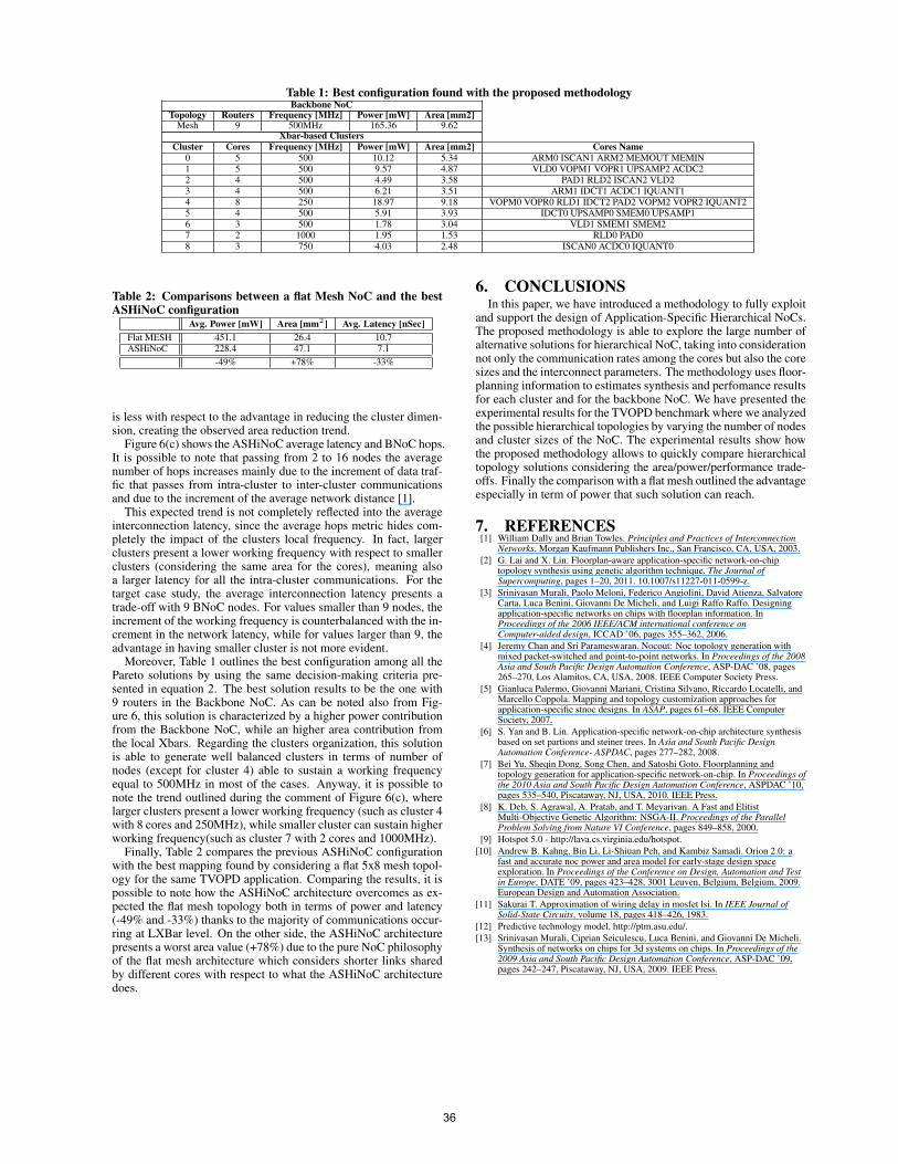
Table 1: Best configuration found with the proposed methodologyBackbone NoC
Topology Routers Frequency [MHz] Power [mW] Area [mm2]Mesh 9 500MHz 165.36 9.62
Xbar-based Clusters
Cluster Cores Frequency [MHz] Power [mW] Area [mm2] Cores Name
0 5 500 10.12 5.34 ARM0 ISCAN1 ARM2 MEMOUT MEMIN1 5 500 9.57 4.87 VLD0 VOPM1 VOPR1 UPSAMP2 ACDC22 4 500 4.49 3.58 PAD1 RLD2 ISCAN2 VLD23 4 500 6.21 3.51 ARM1 IDCT1 ACDC1 IQUANT14 8 250 18.97 9.18 VOPM0 VOPR0 RLD1 IDCT2 PAD2 VOPM2 VOPR2 IQUANT25 4 500 5.91 3.93 IDCT0 UPSAMP0 SMEM0 UPSAMP16 3 500 1.78 3.04 VLD1 SMEM1 SMEM27 2 1000 1.95 1.53 RLD0 PAD08 3 750 4.03 2.48 ISCAN0 ACDC0 IQUANT0
Table 2: Comparisons between a flat Mesh NoC and the bestASHiNoC configuration
Avg. Power [mW] Area [mm2] Avg. Latency [nSec]
Flat MESH 451.1 26.4 10.7ASHiNoC 228.4 47.1 7.1
-49% +78% -33%
is less with respect to the advantage in reducing the cluster dimen-sion, creating the observed area reduction trend.
Figure 6(c) shows the ASHiNoC average latency and BNoC hops.It is possible to note that passing from 2 to 16 nodes the averagenumber of hops increases mainly due to the increment of data traf-fic that passes from intra-cluster to inter-cluster communicationsand due to the increment of the average network distance [1].
This expected trend is not completely reflected into the averageinterconnection latency, since the average hops metric hides com-pletely the impact of the clusters local frequency. In fact, largerclusters present a lower working frequency with respect to smallerclusters (considering the same area for the cores), meaning alsoa larger latency for all the intra-cluster communications. For thetarget case study, the average interconnection latency presents atrade-off with 9 BNoC nodes. For values smaller than 9 nodes, theincrement of the working frequency is counterbalanced with the in-crement in the network latency, while for values larger than 9, theadvantage in having smaller cluster is not more evident.
Moreover, Table 1 outlines the best configuration among all thePareto solutions by using the same decision-making criteria pre-sented in equation 2. The best solution results to be the one with9 routers in the Backbone NoC. As can be noted also from Fig-ure 6, this solution is characterized by a higher power contributionfrom the Backbone NoC, while an higher area contribution fromthe local Xbars. Regarding the clusters organization, this solutionis able to generate well balanced clusters in terms of number ofnodes (except for cluster 4) able to sustain a working frequencyequal to 500MHz in most of the cases. Anyway, it is possible tonote the trend outlined during the comment of Figure 6(c), wherelarger clusters present a lower working frequency (such as cluster 4with 8 cores and 250MHz), while smaller cluster can sustain higherworking frequency(such as cluster 7 with 2 cores and 1000MHz).
Finally, Table 2 compares the previous ASHiNoC configurationwith the best mapping found by considering a flat 5x8 mesh topol-ogy for the same TVOPD application. Comparing the results, it ispossible to note how the ASHiNoC architecture overcomes as ex-pected the flat mesh topology both in terms of power and latency(-49% and -33%) thanks to the majority of communications occur-ring at LXBar level. On the other side, the ASHiNoC architecturepresents a worst area value (+78%) due to the pure NoC philosophyof the flat mesh architecture which considers shorter links sharedby different cores with respect to what the ASHiNoC architecturedoes.
6. CONCLUSIONSIn this paper, we have introduced a methodology to fully exploit
and support the design of Application-Specific Hierarchical NoCs.The proposed methodology is able to explore the large number ofalternative solutions for hierarchical NoC, taking into considerationnot only the communication rates among the cores but also the coresizes and the interconnect parameters. The methodology uses floor-planning information to estimates synthesis and perfomance resultsfor each cluster and for the backbone NoC. We have presented theexperimental results for the TVOPD benchmark where we analyzedthe possible hierarchical topologies by varying the number of nodesand cluster sizes of the NoC. The experimental results show howthe proposed methodology allows to quickly compare hierarchicaltopology solutions considering the area/power/performance trade-offs. Finally the comparison with a flat mesh outlined the advantageespecially in term of power that such solution can reach.
7. REFERENCES[1] William Dally and Brian Towles. Principles and Practices of Interconnection
Networks. Morgan Kaufmann Publishers Inc., San Francisco, CA, USA, 2003.
[2] G. Lai and X. Lin. Floorplan-aware application-specific network-on-chiptopology synthesis using genetic algorithm technique. The Journal ofSupercomputing, pages 1–20, 2011. 10.1007/s11227-011-0599-z.
[3] Srinivasan Murali, Paolo Meloni, Federico Angiolini, David Atienza, SalvatoreCarta, Luca Benini, Giovanni De Micheli, and Luigi Raffo Raffo. Designingapplication-specific networks on chips with floorplan information. InProceedings of the 2006 IEEE/ACM international conference onComputer-aided design, ICCAD ’06, pages 355–362, 2006.
[4] Jeremy Chan and Sri Parameswaran. Nocout: Noc topology generation withmixed packet-switched and point-to-point networks. In Proceedings of the 2008Asia and South Pacific Design Automation Conference, ASP-DAC ’08, pages265–270, Los Alamitos, CA, USA, 2008. IEEE Computer Society Press.
[5] Gianluca Palermo, Giovanni Mariani, Cristina Silvano, Riccardo Locatelli, andMarcello Coppola. Mapping and topology customization approaches forapplication-specific stnoc designs. In ASAP, pages 61–68. IEEE ComputerSociety, 2007.
[6] S. Yan and B. Lin. Application-specific network-on-chip architecture synthesisbased on set partions and steiner trees. In Asia and South Pacific DesignAutomation Conference- ASPDAC, pages 277–282, 2008.
[7] Bei Yu, Sheqin Dong, Song Chen, and Satoshi Goto. Floorplanning andtopology generation for application-specific network-on-chip. In Proceedings ofthe 2010 Asia and South Pacific Design Automation Conference, ASPDAC ’10,pages 535–540, Piscataway, NJ, USA, 2010. IEEE Press.
[8] K. Deb, S. Agrawal, A. Pratab, and T. Meyarivan. A Fast and ElitistMulti-Objective Genetic Algorithm: NSGA-II. Proceedings of the ParallelProblem Solving from Nature VI Conference, pages 849–858, 2000.
[9] Hotspot 5.0 - http://lava.cs.virginia.edu/hotspot.
[10] Andrew B. Kahng, Bin Li, Li-Shiuan Peh, and Kambiz Samadi. Orion 2.0: afast and accurate noc power and area model for early-stage design spaceexploration. In Proceedings of the Conference on Design, Automation and Testin Europe, DATE ’09, pages 423–428, 3001 Leuven, Belgium, Belgium, 2009.European Design and Automation Association.
[11] Sakurai T. Approximation of wiring delay in mosfet lsi. In IEEE Journal ofSolid-State Circuits, volume 18, pages 418–426, 1983.
[12] Predictive technology model, http://ptm.asu.edu/.
[13] Srinivasan Murali, Ciprian Seiculescu, Luca Benini, and Giovanni De Micheli.Synthesis of networks on chips for 3d systems on chips. In Proceedings of the2009 Asia and South Pacific Design Automation Conference, ASP-DAC ’09,pages 242–247, Piscataway, NJ, USA, 2009. IEEE Press.
36