chip removal tool project - core
TRANSCRIPT

Chip Removal Tool Project
A Senior Project
presented to
the Faculty of the Mechanical Engineering
California Polytechnic State University, San Luis Obispo
In Partial Fulfillment
of the Requirements for the Degree
Bachelor of Science
by
Brett Mori
John Cote
Kyle Rowland
Micah Wells
December, 2009

© 2009 Brett Mori, John Cote, Kyle Rowland, Micah Wells
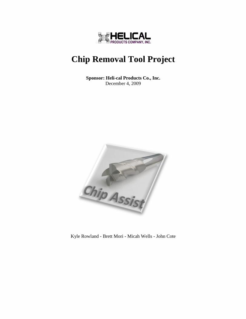
Chip Removal Tool Project
Sponsor: Heli
Kyle Rowland
Chip Removal Tool Project
Sponsor: Heli-cal Products Co., Inc. December 4, 2009
Kyle Rowland - Brett Mori - Micah Wells - John Cote
ii
Statement of Disclaimer
Since this project is a result of a class assignment, it has been graded and accepted as fulfillment of the course requirements. Acceptance does not imply technical accuracy or reliability. Any use of information in this report is done at the risk of the user. These risks may include catastrophic failure of the device or infringement of patent or copyright laws. California Polytechnic State University at San Luis Obispo and its staff cannot be held liable for any use or misuse of the project.
iii
Table of Contents
List of Tables .................................................................................................................................. v
List of Figures ................................................................................................................................. v
List of Nomenclature ..................................................................................................................... vi
Executive Summary ........................................................................................................................ 1
Chapter 1 Introduction .............................................................................................................. 2
Helical Background .................................................................................................................... 2
Our Plan: Flexibility and Integration .......................................................................................... 3
Management Plan........................................................................................................................ 5
Chapter 2 Background .............................................................................................................. 7
The Need for Chip Removal ....................................................................................................... 7
Fanuc Robodrill .......................................................................................................................... 8
Current Chip Handling Methods ................................................................................................. 9
Chapter 3 Design Development .............................................................................................. 10
Chip Diverter ............................................................................................................................ 10
Cylindrical Brush ...................................................................................................................... 11
Fork ........................................................................................................................................... 12
Compressed Air ........................................................................................................................ 12
Concept Selection ..................................................................................................................... 13
Preliminary Testing Methods .................................................................................................... 14
Results of Preliminary Testing.................................................................................................. 15
Safety Considerations ............................................................................................................... 16
Material Selection ..................................................................................................................... 16
Maintenance and repair considerations ..................................................................................... 17
iv
Final Concept Description ........................................................................................................ 17
Chapter 4 Final Designs ......................................................................................................... 23
Design Description.................................................................................................................... 23
Mounting Fixture ...................................................................................................................... 26
Conclusion ................................................................................................................................ 28
Cost Analysis ............................................................................................................................ 28
Bill of Materials ........................................................................................................................ 30
Chapter 5 Product Realization ................................................................................................ 31
Chapter 6 Design Verification Plan ........................................................................................ 32
Test Descriptions ...................................................................................................................... 32
Setup ......................................................................................................................................... 33
Results ....................................................................................................................................... 34
DVP&R ..................................................................................................................................... 35
Chapter 7 Conclusions and Recommendations ...................................................................... 36
References ..................................................................................................................................... 38
Appendix A .................................................................................................................................. A1
QFD – Quality Function Development .................................................................................... A1
Appendix B ................................................................................................................................... B1
Assembly and manufacturing drawings index: ......................................................................... B1
Appendix C ................................................................................................................................... C1
Production Real Estate Optimization ........................................................................................ C1
Appendix D .................................................................................................................................. D1
Gantt Chart of Project .............................................................................................................. D1
Appendix E ................................................................................................................................... E1
Testing Data Sheet .................................................................................................................... E1
v
Appendix F.................................................................................................................................... F1
Final Design Manufacturing Drawings ..................................................................................... F1
List of Tables
Table 1. Engineering requirements ................................................................................................ 3
Table 2. Clamping force calculations for varying height, thickness, and width .......................... 24
Table 3. Data used in production real-estate optimization. .......................................................... 29
Table 4. Bill of materials for final design[4]. ................................................................................ 30
Table 5. Design Verification Plan and Report ............................................................................. 35
List of Figures
Figure 1. Final design including fixtures for parts and cleaning device. ....................................... 1
Figure 2. Examples of Broken (Left) and Bushy (Right) metal shavings. .................................... 7
Figure 3. Fanuc Robodrill with side tool changer[2]. .................................................................... 8
Figure 4. Milling cutter with through-spindle coolant ports[3]. ..................................................... 9
Figure 5. Chip diverter concept solution....................................................................................... 10
Figure 6. Cylindrical brush concept solution. ............................................................................... 11
Figure 7. Chip removing fork concept solution. ........................................................................... 12
Figure 8. Examples of compressed air nozzles. ........................................................................... 13
Figure 9. Preliminary testing using steel wool to simulate chips. ............................................... 16
Figure 10. Top three concepts at the end of the initial design phase. .......................................... 18
Figure 11. Spring loaded hinge prototype created for testing. ...................................................... 19
Figure 12. Soft rubber flap prototype created for testing. ............................................................. 20
Figure 13. Firm rubber flap prototype created for testing. ........................................................... 21
Figure 14. Position of bit directly before entering spring loaded hinge prototype. ...................... 22
Figure 15. Steel prototype devices with varying height, material thickness, and bit entrances. .. 23
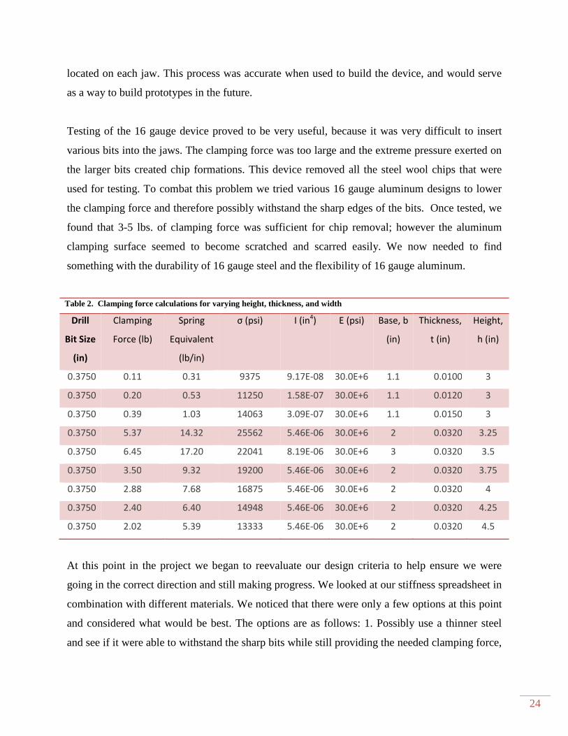
Figure 16. Some examples of different bit entrances ................................................................... 25
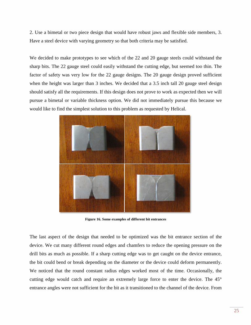
Figure 17. Chip removal device prototypes used to determine final design ................................. 26

vi
Figure 18. Base Plate with reference planes. ................................................................................ 27
Figure 19. Top view of Base Plate with Cleaning Device and Gauge in place. .......................... 27
Figure 20. Front View showing notch in gauge used for locating the cleaning device ............... 28
Figure 21. Comparison of total time to produce 1000 parts using the existing process and
expected process using the Chip Assist device. ............................................................................ 29
List of Nomenclature
Jobber Length Jobber-length drills are the most common type of drill. The length of the
flutes is ten times the diameter of the drill
Pallet A 9.75 x 14.00 inch tooling fixture. Two pallets can be mounted to a table at
a time.
Swarf Also known as turnings, chips, or filings — the debris or waste resulting
from metalworking operations.
Table Area Working area inside the Fanuc robodrill. The robodrill can actively work on
one table at a time, while the second table is located in the side tool changer.
Workpiece Piece of material currently being machined

1
Executive Summary
The Cal Poly senior project team worked with Helical Products Inc. to develop an automated
method for removing swarf and chip buildup from the drill bits of their CNC milling machines.
The removal methods in this report were designed for and tested using a Fanuc Robodrill while
keeping the potential in mind for their use in other CNC milling machines. After extensive
background research, preliminary and prototype design and testing the final chosen design is
shown below. The cleaning device is made from flexible sheet metal and placed on a fixture that
occupies one of the two pallet locations inside the CNC machine. The sheet metal is flexible
enough to accommodate the full range of dill bit sizes requested by Helical and strong enough to
hold the chips in place as the drill bit is removed from the cleaning device, cleaning the drill bit.
Figure 1. Final design including fixtures for parts and cleaning device.

2
Chapter 1 Introduction
Helical Background
Alex Ek, Manufacturing Engineering Manager of Helical Products Co., Inc. has requested the
design and building of a device for removing entangled chips from the tools used to manufacture
their products. Chip buildup on tooling can be a costly and time consuming manufacturing issue.
There are two primary reasons that Helical is experiencing excessive chip build up. First,
material such as stainless steel produces long thread-like chips that get entangled and accumulate
on the drilling tools. Second, due to the work hardening property of stainless steel, the material
hardens during the machining process causing premature wear of tool and difficulty of chip
control. Using a pecking cycle to break the stainless steel chips is inefficient and therefore
requires a more expensive drill bit associated with a dramatic increase in machining time.
The productivity benefits of CNC machine tools are lost when a manual tool cleaning process is
utilized. This manual operation has proved to be a difficult, hazardous, and time consuming
process. The challenge faced by Helical Products is to find a solution which removes the
entangled chips without disrupting the highly efficient CNC machining process. Left
unaddressed, this disruption in the machining process will cost Helical time and money. Not only
is the current method of intervention a time consuming process, but it remains a hazardous task
that puts the CNC operators at risk to injury.
The final design must automatically remove the chips from the specified tooling and operate
within a 5 second time interval per tool. The design must be completely safe to use by the
machine operator and cause no harm to the equipment. There can be no scratches, marks, or
damage to the parts being machined. A complete and innovative solution will be reached while
working under the authority of Helical.

3
Our Plan: Flexibility and Integration
The chip build up problem at Helical requires a solution that is flexible while allowing for
various types of machining processes and the ability to be integrated into current machining
processes and all future machining processes. Therefore, we believe a successful solution must
meet the following objectives:
• Automatic operation with minimum human intervention
• Integration with CNC machine control
• Minimize cleaning time for tool, thus maximizing productivity
• Must not scratch, mark, or damage tools or product
• Accommodate drills of jobber length #56 to 3/8”
• A solution that is robust and reliable, to satisfy the high operational hours demanded by
Helical Products
To meet these objectives, Chip Assist has developed a set of engineering requirements based on
Helical’s needs. To develop the engineering requirements we created a Quality Function
Deployment (QFD) diagram based on Helical’s requirements (Appendix B). Below is a table
summarizing the engineering specifications of this project.
Table 1. Engineering requirements
Spec # Parameter Description Requirements/ Target Tolerance Risk Compliance
1 Automatic Operation No human intervention N/A M A,I 2 Cleaning Cycle Time <5 [seconds] Max H A,T
3 Integration with CNC control
Can be accomplished with existing code N/A L I
4 Reliability 99% Min H A, T
5 Life of Tool between maintenance 1000 [hours] Min H A,T
6 Damage to tools or Product None Min M I
7 Fits Fanuc Robodrill N/A N/A L I 8 Drills Jobber length #56 to 3/8 N/A H A,I 9 Cost, per tool 1000-3000 [USD] Max L A
KEY: Compliance Methods: Analysis (A), Test (T), and Inspection (I)
4
Metal Chip Removal Mechanism Specifications
1. The automatic operation specification requires that no human intervention need take
place during that machining process. Reducing the need for human intervention reduces
the chance of injury to the CNC machinist and also decreases the production time of the
product.
2. The cleaning cycle time must be cost effective and efficient. A maximum cleaning cycle
time of 5 seconds will be an improvement on the current chip removal process. This
specification is listed as high risk because if the cleaning time is too long it will
drastically affect production.
3. The integration with CNC control specification is very important in that the machining
process and chip removal mechanism are operated by the same controller.
4. The chip removal mechanism must be robust and reliable, cleaning tool failures will
result in possible damage to CNC machinery and/or the product.
5. The mechanism must last at least 1000 hours between maintenance. The CNC machines
at Helical are operated up to 10 hours a day and a failure to a chip removal mechanism
may damage the machines or the product itself. This specification is listed as high risk
due to the fact that building a robust chip removal mechanism may affect some of the
other engineering requirements such as cost.
6. The chip removal mechanism must not damage any of Helical’s product, CNC
machinery, or CNC tooling. In the event of an unforeseen collision between the chip
removal device and a machining tool, the cleaning device must yield first.
7. The initial chip removal mechanism is to work with a Fanuc Robodrill. Ideally, the chip
removal mechanism would eventually be integrated into Helical’s various CNC
machines.
8. The mechanism must accommodate a wide variety of drills that are used daily at Helical.
Drills of jobber length #56 to 3/8” have a variety of different widths and lengths to
accommodate with the chip removal mechanism. This specification is listed as high risk
because the CNC machine knows where the tip of each drill is but not the length of each
drill itself.
5
Maximum cost per tool refers to the material and hardware costs to create each tool. The cost of
each tool is dependent on material selection, reliability, and robustness of the mechanism.
Management Plan
Project management is a key component in obtaining a successful chip removal design, by
effectively directing the teams time. A Gantt chart has been generated to help plan and organize
required tasks. The chart is broken up into the three-phases: design, implementation, and testing.
Expected completion of project is December 4th, 2009. The Gantt chart can be seen in Appendix
D.
The division of labor is necessary to efficiently complete all the required tasks. A management
plan was generated from our method of approach and will assist throughout the design period.
John Cote will actively coordinate with Alex Ek of Helical and determine group meetings when
design aspects need discussion. John will also act as a coordinator for the design team by
ensuring adequate completion of required tasks. Brett Mori will plan and establish travel
accommodations when necessary. Throughout the design process, it may be necessary to see the
machinery first hand. This will help in assuring that the design and prototype are going in the
direction desired. The design modeling will also be completed by Brett as needed. Micah Wells
will document the project progress until completion. This will include documentation of
scheduled tasks and all other aspects of the design. The documentation will benefit the team if
changes are needed, by utilizing it as a reference. Micah will also assist in information gathering
for the design as necessary. Kyle Rowland will lead in prototype fabrication. This will include
any required material gathering, tooling, etc. Kyle will also focus on document revision and
formatting with the assistance of John. Any changes to these roles will immediately be expressed
to all parties involved in the project.

6
Part of our management plan is to keep Helical updated on the progress of the team while
providing information on upcoming expectations. Helical can expect the following reports
delivered on these dates:
Final Design Report April 13, 2009
Critical Design Review April 20, 2009
Project Update Report June 1, 2009
Final Project Report December 4, 2009
7
Chapter 2 Background
The Need for Chip Removal
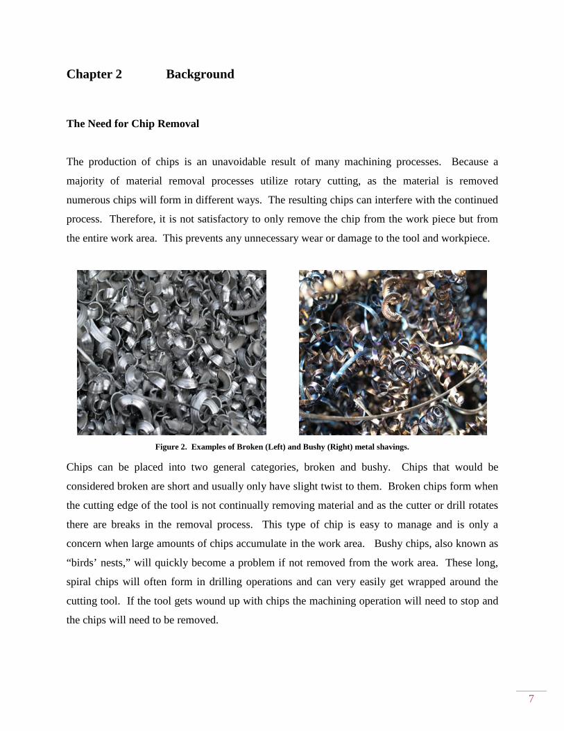
The production of chips is an unavoidable result of many machining processes. Because a
majority of material removal processes utilize rotary cutting, as the material is removed
numerous chips will form in different ways. The resulting chips can interfere with the continued
process. Therefore, it is not satisfactory to only remove the chip from the work piece but from
the entire work area. This prevents any unnecessary wear or damage to the tool and workpiece.
Figure 2. Examples of Broken (Left) and Bushy (Right) metal shavings.
Chips can be placed into two general categories, broken and bushy. Chips that would be
considered broken are short and usually only have slight twist to them. Broken chips form when
the cutting edge of the tool is not continually removing material and as the cutter or drill rotates
there are breaks in the removal process. This type of chip is easy to manage and is only a
concern when large amounts of chips accumulate in the work area. Bushy chips, also known as
“birds’ nests,” will quickly become a problem if not removed from the work area. These long,
spiral chips will often form in drilling operations and can very easily get wrapped around the
cutting tool. If the tool gets wound up with chips the machining operation will need to stop and
the chips will need to be removed.

Fanuc Robodrill
The current system that needs chip removal assistance is the
CNC Drill model α-T14iBs. Some major features of the machine are the 14 tool umbrella
changer and stroke in the horizontal plane of 500 by 400mm.
pallet changer that allows for parts to be continuously run while new parts are loaded onto the
pallet. Spindle speeds range from 80 to 80,000 RPM and fe
The table area is 650 by 400mm and will serve as the mounting surface for any
removal device. The chip removal mechanism will
spindle mounted tool to be cleaned.
Figure
The current system that needs chip removal assistance is the stare-of-the-art
Bs. Some major features of the machine are the 14 tool umbrella
changer and stroke in the horizontal plane of 500 by 400mm. Helical has also purchased a 2
pallet changer that allows for parts to be continuously run while new parts are loaded onto the
Spindle speeds range from 80 to 80,000 RPM and feedrates from 1 to 15,000 mm/min.
is 650 by 400mm and will serve as the mounting surface for any
device. The chip removal mechanism will need to be located in this area
spindle mounted tool to be cleaned.
ure 3. Fanuc Robodrill with side tool changer[2].
8
art Fanuc Robodrill
Bs. Some major features of the machine are the 14 tool umbrella
has also purchased a 2-
pallet changer that allows for parts to be continuously run while new parts are loaded onto the
rates from 1 to 15,000 mm/min.
is 650 by 400mm and will serve as the mounting surface for any passive chip
area in order for the

Current Chip Handling Methods
There are several techniques used today to control formation and interference of
methods go to the formation of the chip to control the problem at the source. The use of coolant
and compressed air will keep the tool and chips cool, preventing them from fusing together.
Special tooling even has channels for coolant to fl
bottom of deep holes.
A common method for keeping the length of the chips to a minimum is something called p
drilling. This operation can be easily added to the machine code and will have the tool
periodically retract from the workpiece to break/clear chips and allow coolant to flow into the
hole. However there are some drawbacks to this process. Work
the tool retracts and coolant rapidly quenches the surface of the wor
additional tool wear every time it has to remove this work
with the proper cutting-edge geometry is required for peck drilling,
Other state-of-the-art tools that can aid in clearing chips are high
coolant tooling. These will literally blast away any removed material and can operate at very
high speeds. However these systems are expensive because it requires modification of the
spindle to accommodate the coolant through the tool.
Figure 4. Milling cutter with through
Current Chip Handling Methods
There are several techniques used today to control formation and interference of
methods go to the formation of the chip to control the problem at the source. The use of coolant
and compressed air will keep the tool and chips cool, preventing them from fusing together.
Special tooling even has channels for coolant to flow built into the cutter to get the coolant to the
A common method for keeping the length of the chips to a minimum is something called p
can be easily added to the machine code and will have the tool
iodically retract from the workpiece to break/clear chips and allow coolant to flow into the
hole. However there are some drawbacks to this process. Work-hardening can occur every time
the tool retracts and coolant rapidly quenches the surface of the workpiece. This will cause
additional tool wear every time it has to remove this work-hardened material. A special tool
edge geometry is required for peck drilling, which is another drawback
tools that can aid in clearing chips are high-pressure through spindle
coolant tooling. These will literally blast away any removed material and can operate at very
high speeds. However these systems are expensive because it requires modification of the
spindle to accommodate the coolant through the tool.
. Milling cutter with through -spindle coolant ports[3].
9
There are several techniques used today to control formation and interference of chips. These
methods go to the formation of the chip to control the problem at the source. The use of coolant
and compressed air will keep the tool and chips cool, preventing them from fusing together.
ow built into the cutter to get the coolant to the
A common method for keeping the length of the chips to a minimum is something called peck-
can be easily added to the machine code and will have the tool
iodically retract from the workpiece to break/clear chips and allow coolant to flow into the
hardening can occur every time
kpiece. This will cause
hardened material. A special tool
another drawback[1].
pressure through spindle
coolant tooling. These will literally blast away any removed material and can operate at very
high speeds. However these systems are expensive because it requires modification of the

10
The problem of chip handling can be solved many ways. Newer advanced techniques have high
up-front costs but good results. Currently the machine operators at Helical are periodically
removing chips from the tools by hand. This solution can be dangerous and frequently interrupts
certain machining processes. A low-cost solution is desired to replace the current manual action
increasing safety and product output.
Chapter 3 Design Development
Chip Diverter
A chip diverter is to limit the buildup of chips on the drill bit by diverting the chips away from
the drill as the chips are forming. The concept shown in Figure 5 consists of three main features.
The first feature is a set screw that is located on the top half of the diverter. This set screw would
be tightened to hold the diverter in place on the drill bit. The second feature is the conical shape
on the bottom of the chip diverter which is used to push the chips located on the outside the drill
bit away from the bit, allowing them to fall off without getting caught in the drill bit. The last
feature is the threads located inside of the chip diverter. These threads would fit into the flutes of
the drill bit serving two purposes. The first purpose is to help hold the chip diverter in place on
the drill bit and the second is to push chips located inside the flutes of the drill bit to the outside
where they can be removed.
Figure 5. Chip diverter concept solution.
This concept meets our design specifications by providing the passive automatic operation, has
no cleaning cycle time and would easily be integrated into the existing equipment. It would
11
require no “real estate” on the CNC table and would be inexpensive to produce. A primary
drawback is that multiple sizes would have to be made to fit different tools.
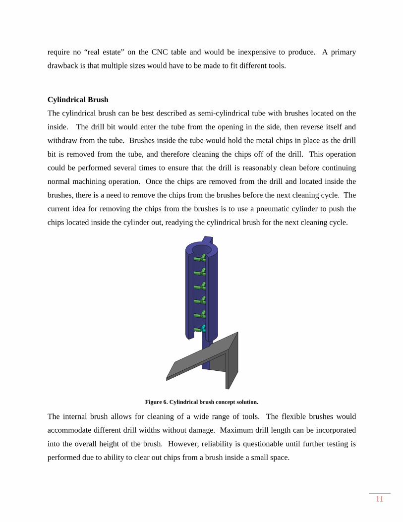
Cylindrical Brush
The cylindrical brush can be best described as semi-cylindrical tube with brushes located on the
inside. The drill bit would enter the tube from the opening in the side, then reverse itself and
withdraw from the tube. Brushes inside the tube would hold the metal chips in place as the drill
bit is removed from the tube, and therefore cleaning the chips off of the drill. This operation
could be performed several times to ensure that the drill is reasonably clean before continuing
normal machining operation. Once the chips are removed from the drill and located inside the
brushes, there is a need to remove the chips from the brushes before the next cleaning cycle. The
current idea for removing the chips from the brushes is to use a pneumatic cylinder to push the
chips located inside the cylinder out, readying the cylindrical brush for the next cleaning cycle.
Figure 6. Cylindrical brush concept solution.
The internal brush allows for cleaning of a wide range of tools. The flexible brushes would
accommodate different drill widths without damage. Maximum drill length can be incorporated
into the overall height of the brush. However, reliability is questionable until further testing is
performed due to ability to clear out chips from a brush inside a small space.
12
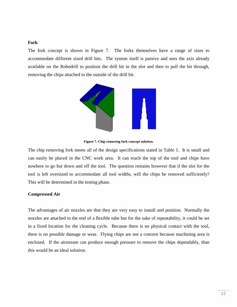
Fork
The fork concept is shown in Figure 7. The forks themselves have a range of sizes to
accommodate different sized drill bits. The system itself is passive and uses the axis already
available on the Robodrill to position the drill bit in the slot and then to pull the bit through,
removing the chips attached to the outside of the drill bit.
Figure 7. Chip removing fork concept solution.
The chip removing fork meets all of the design specifications stated in Table 1. It is small and
can easily be placed in the CNC work area. It can reach the top of the tool and chips have
nowhere to go but down and off the tool. The question remains however that if the slot for the
tool is left oversized to accommodate all tool widths, will the chips be removed sufficiently?
This will be determined in the testing phase.
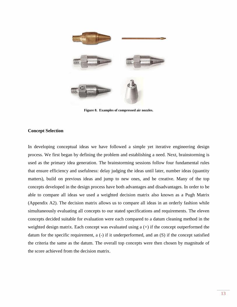
Compressed Air
The advantages of air nozzles are that they are very easy to install and position. Normally the
nozzles are attached to the end of a flexible tube but for the sake of repeatability, it could be set
in a fixed location for the cleaning cycle. Because there is no physical contact with the tool,
there is no possible damage or wear. Flying chips are not a concern because machining area is
enclosed. If the airstream can produce enough pressure to remove the chips dependably, than
this would be an ideal solution.
13
Figure 8. Examples of compressed air nozzles.
Concept Selection
In developing conceptual ideas we have followed a simple yet iterative engineering design
process. We first began by defining the problem and establishing a need. Next, brainstorming is
used as the primary idea generation. The brainstorming sessions follow four fundamental rules
that ensure efficiency and usefulness: delay judging the ideas until later, number ideas (quantity
matters), build on previous ideas and jump to new ones, and be creative. Many of the top
concepts developed in the design process have both advantages and disadvantages. In order to be
able to compare all ideas we used a weighted decision matrix also known as a Pugh Matrix
(Appendix A2). The decision matrix allows us to compare all ideas in an orderly fashion while
simultaneously evaluating all concepts to our stated specifications and requirements. The eleven
concepts decided suitable for evaluation were each compared to a datum cleaning method in the
weighted design matrix. Each concept was evaluated using a (+) if the concept outperformed the
datum for the specific requirement, a (-) if it underperformed, and an (S) if the concept satisfied
the criteria the same as the datum. The overall top concepts were then chosen by magnitude of
the score achieved from the decision matrix.
14
Preliminary Testing Methods
The goal of the preliminary testing is to evaluate as many methods as possible of removing chips
from the drill bits by manual means. This testing will provide us with information on the success
rates of various methods of chip removal and based upon the information collected, as well as
input from Alex Ek, we will choose a method and design a mechanical system to automate the
chip removal process.
To test the fundamentals of each idea the team must generate mockups which attempt to perform
the chip removal operation. The creations of the top concepts are as follows:
High Pressure Air- The high pressure air used in preliminary testing will be in the most basic
form. Air nozzles with 80 psi will be used to determine if chip prevention can be accomplished
from different nozzle positions. The nozzle location in the radial and vertical direction must be
optimized in order to get the most efficient chip prevention. Different nozzle types will also be
used to increase or decrease the air flow into the chip.
Exterior Brush- To replicate the exterior brush idea the team will be using different types of
brushes and drill movements to check the efficiency of chip removal. The bristles of these
brushes will range from very soft to that similar of a wire brush.
Interior Brush- The preliminary interior brush test will also include the different brushes used in
the exterior brush tests. The brushes will be curved, or used in combination with each other to
determine which method is most effective.
Slotted Fork- The preliminary slotted fork testing will be accomplished with an aluminum fork.
This fork can be created from a piece of aluminum plating which is the desired thickness and
outer dimensions. A slot which is slightly larger than the testing bit can then be cut into the
aluminum plate and therefore creating the necessary fork.
15
The team believes that the generation of all these preliminary testing devices can be created on
the Cal Poly campus, however if any manufacturing issues arise we will contact Alex Ek for
assistance. Helical has a full time in-house tooling department which can assist in fabrication of
any concept.
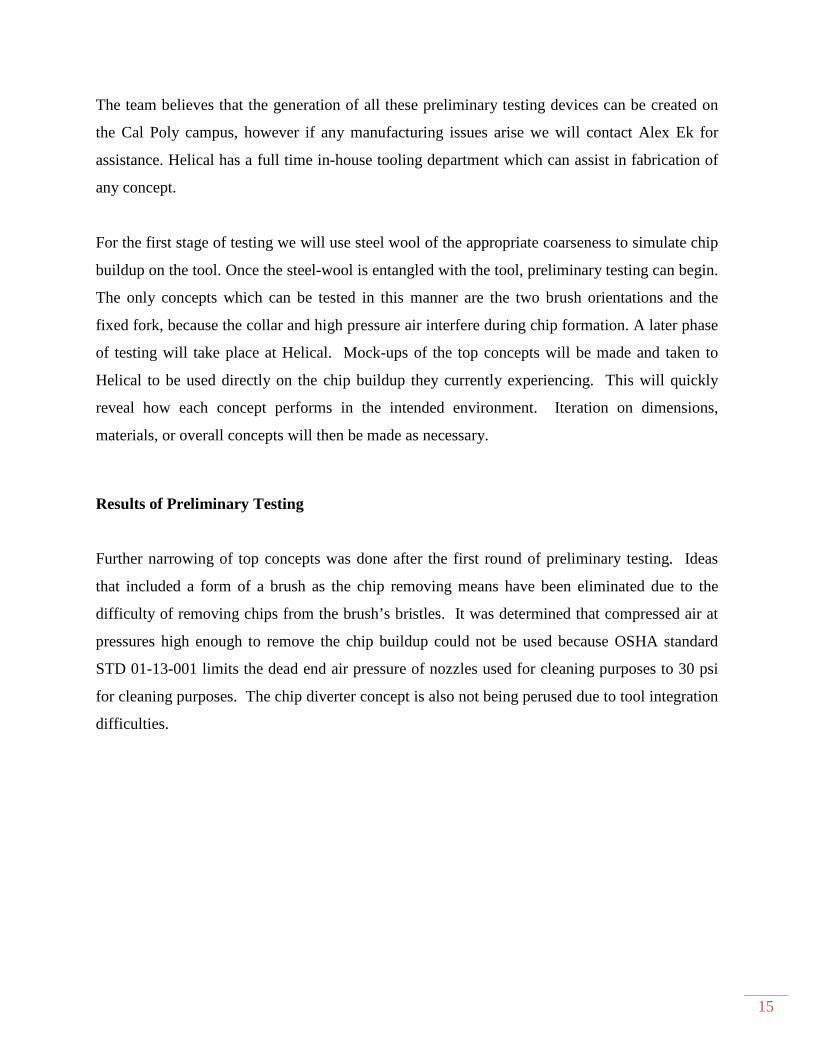
For the first stage of testing we will use steel wool of the appropriate coarseness to simulate chip
buildup on the tool. Once the steel-wool is entangled with the tool, preliminary testing can begin.
The only concepts which can be tested in this manner are the two brush orientations and the
fixed fork, because the collar and high pressure air interfere during chip formation. A later phase
of testing will take place at Helical. Mock-ups of the top concepts will be made and taken to
Helical to be used directly on the chip buildup they currently experiencing. This will quickly
reveal how each concept performs in the intended environment. Iteration on dimensions,
materials, or overall concepts will then be made as necessary.
Results of Preliminary Testing
Further narrowing of top concepts was done after the first round of preliminary testing. Ideas
that included a form of a brush as the chip removing means have been eliminated due to the
difficulty of removing chips from the brush’s bristles. It was determined that compressed air at
pressures high enough to remove the chip buildup could not be used because OSHA standard
STD 01-13-001 limits the dead end air pressure of nozzles used for cleaning purposes to 30 psi
for cleaning purposes. The chip diverter concept is also not being perused due to tool integration
difficulties.
Figure 9. Preliminary testing using steel wool to simulate chips.
Testing reveals that pulling the drill through a slot in rigid material reliably and easily removes
chips despite their quantity and tightness on tool.
12. A single sized slot however did not effectively remove chips on both the largest and smallest
expected drill sizes. Therefore, in the
proposed for a mock-up and retest.
Safety Considerations
Because our device will be enclosed inside the Robodrill work area, operators will be safe from
any possible occurrence during the
electromagnetic lock so the machine will not operate if it is open. If the hinged chip removing
design is implemented, pinch points will need to be considered. When the device is being
installed or undergoing maintenance, it will be handled by Helical staff. The design dimensions
and geometry must account for possible harm done to hands and fingers. Sharp edges must be
removed by beveling edges and rounding off corners.
Material Selection
The frame structure will need to be robust enough to withstand repeated impact of tooling at the
chip removal location. Also, if something goes wrong and the tool collides with the device, it is
preferable that the tool is broken and the chip remover stays intact.
. Preliminary testing using steel wool to simulate chips.
Testing reveals that pulling the drill through a slot in rigid material reliably and easily removes
chips despite their quantity and tightness on tool. This slot simulates the Fork concept on page
. A single sized slot however did not effectively remove chips on both the largest and smallest
expected drill sizes. Therefore, in the next design iteration, a slot that adjusts to the tool size
up and retest.
Because our device will be enclosed inside the Robodrill work area, operators will be safe from
any possible occurrence during the cleaning operation. The door to the Robodrill has an
electromagnetic lock so the machine will not operate if it is open. If the hinged chip removing
design is implemented, pinch points will need to be considered. When the device is being
dergoing maintenance, it will be handled by Helical staff. The design dimensions
and geometry must account for possible harm done to hands and fingers. Sharp edges must be
removed by beveling edges and rounding off corners.
structure will need to be robust enough to withstand repeated impact of tooling at the
chip removal location. Also, if something goes wrong and the tool collides with the device, it is
preferable that the tool is broken and the chip remover stays intact. Therefore the final design
16
Testing reveals that pulling the drill through a slot in rigid material reliably and easily removes
Fork concept on page
. A single sized slot however did not effectively remove chips on both the largest and smallest
next design iteration, a slot that adjusts to the tool size is
Because our device will be enclosed inside the Robodrill work area, operators will be safe from
cleaning operation. The door to the Robodrill has an
electromagnetic lock so the machine will not operate if it is open. If the hinged chip removing
design is implemented, pinch points will need to be considered. When the device is being
dergoing maintenance, it will be handled by Helical staff. The design dimensions
and geometry must account for possible harm done to hands and fingers. Sharp edges must be
structure will need to be robust enough to withstand repeated impact of tooling at the
chip removal location. Also, if something goes wrong and the tool collides with the device, it is
Therefore the final design
17
will probably be made of some type of steel. A high carbon steel can withstand surface wear
which is another concern because of the frequent metal on metal contact with the chips. If a
flexible element like rubber is used as part of the device, it will need to be able to withstand
constant presence of oil based coolant. It will also need to be durable enough to withstand chip
contact while remaining flexible enough to accommodate the various drill sizes.
Maintenance and repair considerations
The device needs to be designed for low maintenance. Because of the relatively low forces
involved, yield is not a concern. However, in the design with the flexible element, the only
concern of wear is in the material that contacts the tool and chips. The flexible element is
installed with fasteners, so that it can easily be replaced. It is uncertain how often this will need
to be done, but a material will be chosen to reduce replacement as much as possible.
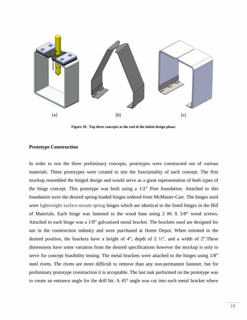
Final Concept Description
In all three top concepts the drill approaches the cleaning device from the front or back, pushes
the guides apart, the spindle slowly reverses and moves upward as the chips are forced off. The
rubber flap concept which can be seen in Figure 10a uses two flexible rubber flaps that are bolted
in place. The bottom of the rubber flaps are contoured so that the flap will deflect upward as the
drill bit is inserted from the side. The sloped and right angle flap concepts seen in Figure 10b, c
use spring-loaded, self-closing hinges to hold the flaps against the drill bit while the drill bit is
inserted. Each of the hinged concepts need an L-bracket installed on the inside of the hinges to
prevent the hinges from closing more than 90 degrees. A #33 and 3/8 inch drill bit are shown in
Figure 10a to demonstrate the range of sizes that need to be accommodated. All manufacturing
and part drawings can be found in Appendix B.
18
Figure 10. Top three concepts at the end of the initial design phase.
Prototype Construction
In order to test the three preliminary concepts, prototypes were constructed out of various
materials. These prototypes were created to test the functionality of each concept. The first
mockup resembled the hinged design and would serve as a great representation of both types of
the hinge concept. This prototype was built using a 1/2” Pine foundation. Attached to this
foundation were the desired spring-loaded hinges ordered from McMaster-Carr. The hinges used
were lightweight surface-mount spring hinges which are identical to the listed hinges in the Bill
of Materials. Each hinge was fastened to the wood base using 2 #6 X 5/8” wood screws.
Attached to each hinge was a 1/8” galvanized metal bracket. The brackets used are designed for
use in the construction industry and were purchased at Home Depot. When oriented in the
desired position, the brackets have a height of 4”, depth of 2 ½”, and a width of 2”.These
dimensions have some variation from the desired specifications however the mockup is only to
serve for concept feasibility testing. The metal brackets were attached to the hinges using 1/8”
steel rivets. The rivets are more difficult to remove than any non-permanent fastener, but for
preliminary prototype construction it is acceptable. The last task performed on the prototype was
to create an entrance angle for the drill bit. A 45° angle was cut into each metal bracket where
19
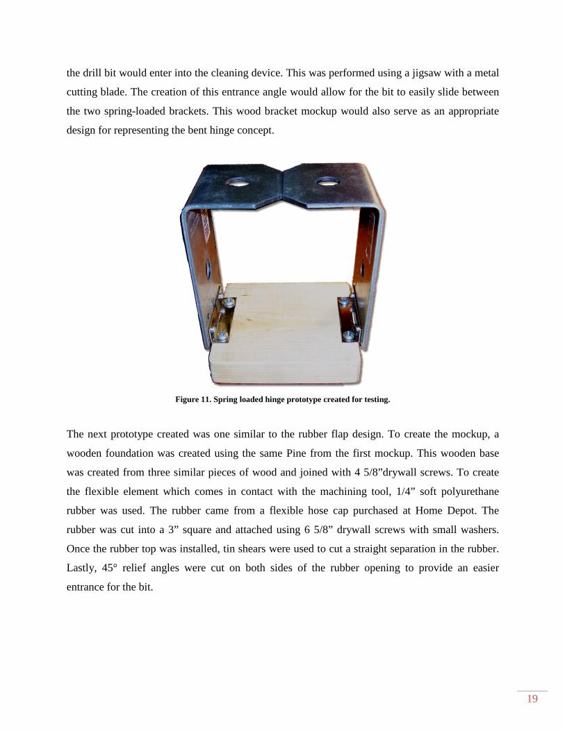
the drill bit would enter into the cleaning device. This was performed using a jigsaw with a metal
cutting blade. The creation of this entrance angle would allow for the bit to easily slide between
the two spring-loaded brackets. This wood bracket mockup would also serve as an appropriate
design for representing the bent hinge concept.
Figure 11. Spring loaded hinge prototype created for testing.
The next prototype created was one similar to the rubber flap design. To create the mockup, a
wooden foundation was created using the same Pine from the first mockup. This wooden base
was created from three similar pieces of wood and joined with 4 5/8”drywall screws. To create
the flexible element which comes in contact with the machining tool, 1/4” soft polyurethane
rubber was used. The rubber came from a flexible hose cap purchased at Home Depot. The
rubber was cut into a 3” square and attached using 6 5/8” drywall screws with small washers.
Once the rubber top was installed, tin shears were used to cut a straight separation in the rubber.
Lastly, 45° relief angles were cut on both sides of the rubber opening to provide an easier
entrance for the bit.

20
Figure 12. Soft rubber flap prototype created for testing.
Another prototype was assembled to help show which aspects of the rubber flap design would
work best. This prototype was created using the same process as before and only the flexible
element was altered. The flexible element used was 1/8” firm polyurethane rubber. This rubber
was thinner and less flexible than the rubber used before. A slot approximately 1/16” in width
was cut along the entire depth in order to provide for the drill bit entrance.
21
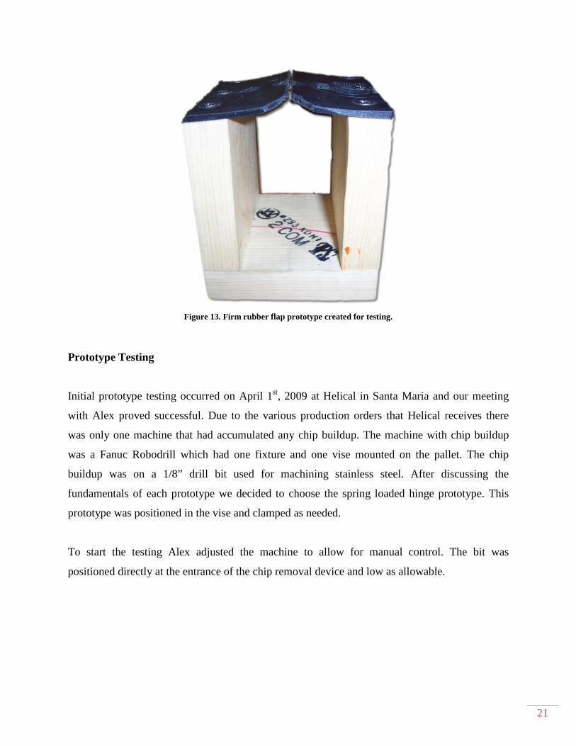
Figure 13. Firm rubber flap prototype created for testing.
Prototype Testing
Initial prototype testing occurred on April 1st, 2009 at Helical in Santa Maria and our meeting
with Alex proved successful. Due to the various production orders that Helical receives there
was only one machine that had accumulated any chip buildup. The machine with chip buildup
was a Fanuc Robodrill which had one fixture and one vise mounted on the pallet. The chip
buildup was on a 1/8” drill bit used for machining stainless steel. After discussing the
fundamentals of each prototype we decided to choose the spring loaded hinge prototype. This
prototype was positioned in the vise and clamped as needed.
To start the testing Alex adjusted the machine to allow for manual control. The bit was
positioned directly at the entrance of the chip removal device and low as allowable.
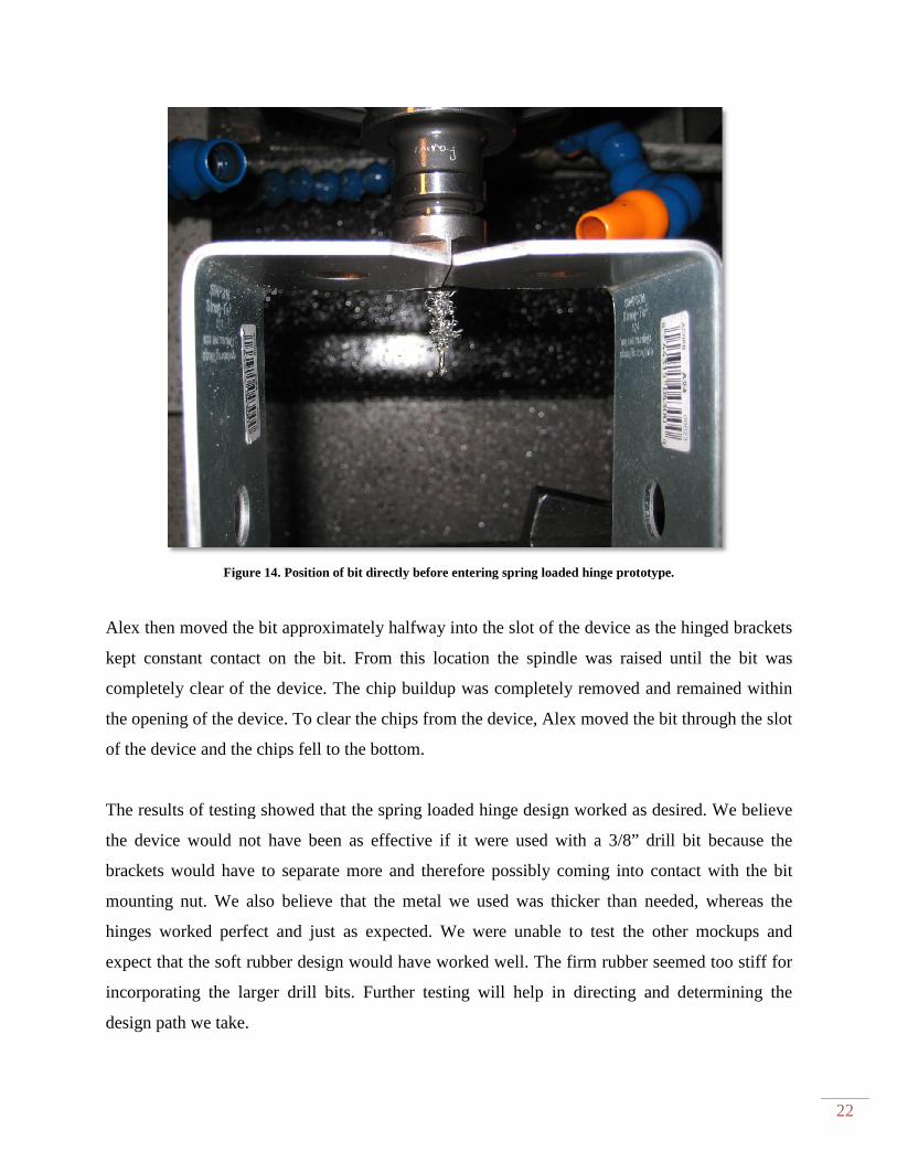
Figure 14. Position of bit directly befo
Alex then moved the bit approximately halfway into the slot of the device as the hinged brackets
kept constant contact on the bit.
completely clear of the device. The chip buildup was completely removed and remained within
the opening of the device. To clear the chips from the device, Alex moved the bit through the slot
of the device and the chips fell to the bottom.
The results of testing showed that t
the device would not have been as effective if it were used with a 3/8” drill bit because the
brackets would have to separate more and therefore possibly coming into contact with the bit
mounting nut. We also believe that the metal we used was thicker than needed, whereas the
hinges worked perfect and just as expected. We were unable to test the other mockups and
expect that the soft rubber design would have worked well. The firm rubber seemed too
incorporating the larger drill bits. Further testing will help in directing and determining the
design path we take.
. Position of bit directly before entering spring loaded hinge prototype.
Alex then moved the bit approximately halfway into the slot of the device as the hinged brackets
kept constant contact on the bit. From this location the spindle was raised until the bit was
the device. The chip buildup was completely removed and remained within
the opening of the device. To clear the chips from the device, Alex moved the bit through the slot
of the device and the chips fell to the bottom.
The results of testing showed that the spring loaded hinge design worked as desired. We believe
the device would not have been as effective if it were used with a 3/8” drill bit because the
brackets would have to separate more and therefore possibly coming into contact with the bit
nut. We also believe that the metal we used was thicker than needed, whereas the
hinges worked perfect and just as expected. We were unable to test the other mockups and
expect that the soft rubber design would have worked well. The firm rubber seemed too
incorporating the larger drill bits. Further testing will help in directing and determining the
22
re entering spring loaded hinge prototype.
Alex then moved the bit approximately halfway into the slot of the device as the hinged brackets
From this location the spindle was raised until the bit was
the device. The chip buildup was completely removed and remained within
the opening of the device. To clear the chips from the device, Alex moved the bit through the slot
design worked as desired. We believe
the device would not have been as effective if it were used with a 3/8” drill bit because the
brackets would have to separate more and therefore possibly coming into contact with the bit
nut. We also believe that the metal we used was thicker than needed, whereas the
hinges worked perfect and just as expected. We were unable to test the other mockups and
expect that the soft rubber design would have worked well. The firm rubber seemed too stiff for
incorporating the larger drill bits. Further testing will help in directing and determining the
Chapter 4 Final Design
Design Description
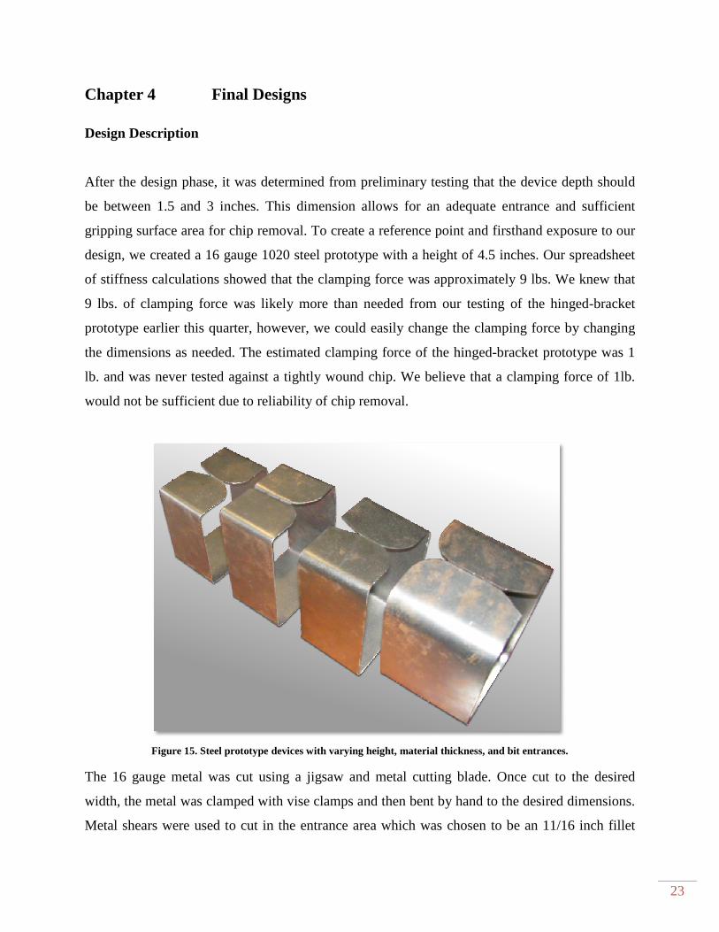
After the design phase, it was determined from preliminary testing that the device depth should
be between 1.5 and 3 inches. This dimension allows for an adequate entrance and sufficient
gripping surface area for chip removal. To create a reference point a
design, we created a 16 gauge 1020 steel prototype with a height of 4.5 inches. Our
of stiffness calculations showed that the clamping force was approximately
9 lbs. of clamping force was likely
prototype earlier this quarter, however, we could easily change the clamping force by changing
the dimensions as needed. The estimated clamping force of the hinged
lb. and was never tested against a tightly wound chip. We believe that a clamping force of 1lb.
would not be sufficient due to reliability of chip removal.
Figure 15. Steel prototype devices with varying height, material thickness, and bit
The 16 gauge metal was cut using a jigsaw and metal cutting blade. Once cut to the desired
width, the metal was clamped with vise clamps and then bent by hand to the desired dimensions.
Metal shears were used to cut in the entrance area which wa
Final Designs
After the design phase, it was determined from preliminary testing that the device depth should
be between 1.5 and 3 inches. This dimension allows for an adequate entrance and sufficient
surface area for chip removal. To create a reference point and firsthand exposure to our
design, we created a 16 gauge 1020 steel prototype with a height of 4.5 inches. Our
showed that the clamping force was approximately 9 lbs. We knew tha
. of clamping force was likely more than needed from our testing of the hinged
prototype earlier this quarter, however, we could easily change the clamping force by changing
the dimensions as needed. The estimated clamping force of the hinged-bracket prototype was 1
never tested against a tightly wound chip. We believe that a clamping force of 1lb.
would not be sufficient due to reliability of chip removal.
Steel prototype devices with varying height, material thickness, and bit entrances.
The 16 gauge metal was cut using a jigsaw and metal cutting blade. Once cut to the desired
width, the metal was clamped with vise clamps and then bent by hand to the desired dimensions.
Metal shears were used to cut in the entrance area which was chosen to be an 11/16 inch fillet
23
After the design phase, it was determined from preliminary testing that the device depth should
be between 1.5 and 3 inches. This dimension allows for an adequate entrance and sufficient
nd firsthand exposure to our
design, we created a 16 gauge 1020 steel prototype with a height of 4.5 inches. Our spreadsheet
lbs. We knew that
more than needed from our testing of the hinged-bracket
prototype earlier this quarter, however, we could easily change the clamping force by changing
bracket prototype was 1
never tested against a tightly wound chip. We believe that a clamping force of 1lb.
entrances.
The 16 gauge metal was cut using a jigsaw and metal cutting blade. Once cut to the desired
width, the metal was clamped with vise clamps and then bent by hand to the desired dimensions.
s chosen to be an 11/16 inch fillet
24
located on each jaw. This process was accurate when used to build the device, and would serve
as a way to build prototypes in the future.
Testing of the 16 gauge device proved to be very useful, because it was very difficult to insert
various bits into the jaws. The clamping force was too large and the extreme pressure exerted on
the larger bits created chip formations. This device removed all the steel wool chips that were
used for testing. To combat this problem we tried various 16 gauge aluminum designs to lower
the clamping force and therefore possibly withstand the sharp edges of the bits. Once tested, we
found that 3-5 lbs. of clamping force was sufficient for chip removal; however the aluminum
clamping surface seemed to become scratched and scarred easily. We now needed to find
something with the durability of 16 gauge steel and the flexibility of 16 gauge aluminum.
Table 2. Clamping force calculations for varying height, thickness, and width
Drill
Bit Size
(in)
Clamping
Force (lb)
Spring
Equivalent
(lb/in)
σ (psi) I (in4) E (psi) Base, b
(in)
Thickness,
t (in)
Height,
h (in)
0.3750 0.11 0.31 9375 9.17E-08 30.0E+6 1.1 0.0100 3
0.3750 0.20 0.53 11250 1.58E-07 30.0E+6 1.1 0.0120 3
0.3750 0.39 1.03 14063 3.09E-07 30.0E+6 1.1 0.0150 3
0.3750 5.37 14.32 25562 5.46E-06 30.0E+6 2 0.0320 3.25
0.3750 6.45 17.20 22041 8.19E-06 30.0E+6 3 0.0320 3.5
0.3750 3.50 9.32 19200 5.46E-06 30.0E+6 2 0.0320 3.75
0.3750 2.88 7.68 16875 5.46E-06 30.0E+6 2 0.0320 4
0.3750 2.40 6.40 14948 5.46E-06 30.0E+6 2 0.0320 4.25
0.3750 2.02 5.39 13333 5.46E-06 30.0E+6 2 0.0320 4.5
At this point in the project we began to reevaluate our design criteria to help ensure we were
going in the correct direction and still making progress. We looked at our stiffness spreadsheet in
combination with different materials. We noticed that there were only a few options at this point
and considered what would be best. The options are as follows: 1. Possibly use a thinner steel
and see if it were able to withstand the sharp bits while still providing the needed clamping force,
2. Use a bimetal or two piece design that would have robust
Have a steel device with varying geometry so that both criteria may be satisfied.
We decided to make prototypes to see which of the 22 and 20 gauge steels could withstand the
sharp bits. The 22 gauge steel could easily withstand the cutting edge, but seemed too thin. The
factor of safety was very low for the 22 gauge designs. The 20
when the height was larger than 3 inches. We decided that a 3.5 inch tal
should satisfy all the requirements. If this design does not prove to work as expected
pursue a bimetal or variable thickness option. We did not immediately pursue this because we
would like to find the simplest solutio
Figure
The last aspect of the design that needed to be optimized was the bit entrance section of the
device. We cut many different round edges and chamfers to reduce the opening pressure on the
drill bits as much as possible. If a sharp cutting edge was to get ca
the bit could bend or break depending on the diameter or the device could deform permanently.
We noticed that the round constant radius edges worked most of the time. Occasionally, the
cutting edge would catch and require an ex
entrance angles were not sufficient for the bit as it transitioned to the channel of the device. From
piece design that would have robust jaws and flexible side members,
Have a steel device with varying geometry so that both criteria may be satisfied.
prototypes to see which of the 22 and 20 gauge steels could withstand the
its. The 22 gauge steel could easily withstand the cutting edge, but seemed too thin. The
factor of safety was very low for the 22 gauge designs. The 20 gauge design proved sufficient
when the height was larger than 3 inches. We decided that a 3.5 inch tall 20 gauge steel design
should satisfy all the requirements. If this design does not prove to work as expected
pursue a bimetal or variable thickness option. We did not immediately pursue this because we
would like to find the simplest solution to this problem as requested by Helical.
Figure 16. Some examples of different bit entrances
The last aspect of the design that needed to be optimized was the bit entrance section of the
device. We cut many different round edges and chamfers to reduce the opening pressure on the
drill bits as much as possible. If a sharp cutting edge was to get caught on the device entrance,
the bit could bend or break depending on the diameter or the device could deform permanently.
We noticed that the round constant radius edges worked most of the time. Occasionally, the
cutting edge would catch and require an extremely large force to enter the device. The 45°
entrance angles were not sufficient for the bit as it transitioned to the channel of the device. From
25
jaws and flexible side members, 3.
Have a steel device with varying geometry so that both criteria may be satisfied.
prototypes to see which of the 22 and 20 gauge steels could withstand the
its. The 22 gauge steel could easily withstand the cutting edge, but seemed too thin. The
gauge design proved sufficient
l 20 gauge steel design
should satisfy all the requirements. If this design does not prove to work as expected then we will
pursue a bimetal or variable thickness option. We did not immediately pursue this because we
The last aspect of the design that needed to be optimized was the bit entrance section of the
device. We cut many different round edges and chamfers to reduce the opening pressure on the
ught on the device entrance,
the bit could bend or break depending on the diameter or the device could deform permanently.
We noticed that the round constant radius edges worked most of the time. Occasionally, the
tremely large force to enter the device. The 45°
entrance angles were not sufficient for the bit as it transitioned to the channel of the device. From
a wide range of testing bit sizes and methods we found that the more acute entrance angles
worked well. To help ease the movement
transition.
Figure 17. Chip removal device prototypes used to determine final design
Mounting Fixture
Initially the base plate that the cleaning fixture was to be mounted to was a flat piece of cast
ground aluminum with four tapped holes to secure the fixture. Although this fixture would work
to mount the cleaning device, the location of the fixture would change every time a new
was installed. The updated base plate for the
center of the plate is machined to provide tw
device and the other for locating the gauge. The cleaning device is to be placed over the four
tapped holes in the center and against reference
piece of angle iron with a notch for locating the cleaning device, is then placed on top of the
raised area and against reference
a wide range of testing bit sizes and methods we found that the more acute entrance angles
movement into the channel, we rounded the edge that exists in that
Chip removal device prototypes used to determine final design
that the cleaning fixture was to be mounted to was a flat piece of cast
ground aluminum with four tapped holes to secure the fixture. Although this fixture would work
to mount the cleaning device, the location of the fixture would change every time a new
base plate for the cleaning fixture is shown below in
center of the plate is machined to provide two reference planes, one for locating the cleaning
device and the other for locating the gauge. The cleaning device is to be placed over the four
tapped holes in the center and against reference plane A. The gauge, which is constructed from a
le iron with a notch for locating the cleaning device, is then placed on top of the
raised area and against reference plane B.
26
a wide range of testing bit sizes and methods we found that the more acute entrance angles
into the channel, we rounded the edge that exists in that
that the cleaning fixture was to be mounted to was a flat piece of cast
ground aluminum with four tapped holes to secure the fixture. Although this fixture would work
to mount the cleaning device, the location of the fixture would change every time a new fixture
fixture is shown below in Figure 18. The
, one for locating the cleaning
device and the other for locating the gauge. The cleaning device is to be placed over the four
A. The gauge, which is constructed from a
le iron with a notch for locating the cleaning device, is then placed on top of the

27
Figure 18. Base Plate with reference planes.
Figure 19. Top view of Base Plate with Cleaning Device and Gauge in place.
Figure 20 is a front view of where the gap in the cleaning device and gauge overlap. The
cleaning device is to be positioned where the gap in the cleaning device and the notch in the
gauge overlap. Once the cleaning device is in its proper position the bolts for the cleaning device
are to be tightened and the gauge removed.
Gauge
Cleaning Device
Reference Plane
Reference Plane
B

28
Figure 20. Front View showing notch in gauge used for locating the cleaning device
Conclusion
It has been agreed that the device and other tooling will be manufactured on-site at the Heli-Cal
plant. Over the summer Heli-Cal will use the device in their manufacturing process to determine
if the device meets all of the design requirements or if any further iteration is required. The Cal
Poly team will provide some guidelines for collecting data during this testing phase.
Cost Analysis
During the design process it was beneficial to determine how much existing pallet production
space could be removed. The chip removal design has to occupy or interfere with the minimal
amount of real estate in order to maintain a profitable process. Instead of completely focusing on
costs and profits we decided to assume that any time saved would correspond to lower
production costs and therefore higher profits. The assumptions necessary for a cost analysis
would compromise the credibility of the end result.
The optimization began with a detailed look of a pallet consisting of sixteen 0.75 inch diameter
parts made of 17-4 stainless steel. The fundamental data used in the analysis was given to us by
Alex Ek. The design specifications relating to time are also included and presented in Table 3.
Gap in Cleaning
Notch in Gauge
29
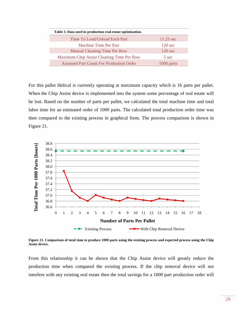
Table 3. Data used in production real-estate optimization.
Time To Load/Unload Each Part 11.25 sec
Machine Time Per Part 120 sec Manual Cleaning Time Per Row 120 sec
Maximum Chip Assist Cleaning Time Per Row 5 sec
Assumed Part Count For Production Order 1000 parts
For this pallet Helical is currently operating at maximum capacity which is 16 parts per pallet.
When the Chip Assist device is implemented into the system some percentage of real estate will
be lost. Based on the number of parts per pallet, we calculated the total machine time and total
labor time for an estimated order of 1000 parts. The calculated total production order time was
then compared to the existing process in graphical form. The process comparison is shown in
Figure 21.
Figure 21. Comparison of total time to produce 1000 parts using the existing process and expected process using the Chip Assist device.
From this relationship it can be shown that the Chip Assist device will greatly reduce the
production time when compared the existing process. If the chip removal device will not
interfere with any existing real estate then the total savings for a 1000 part production order will
36.6
36.8
37.0
37.2
37.4
37.6
37.8
38.0
38.2
38.4
38.6
38.8
0 1 2 3 4 5 6 7 8 9 10 11 12 13 14 15 16 17 18
Tota
l Tim
e P
er 1
000
Par
ts [h
ours
]
Number of Parts Per Pallet
Existing Process With Chip Removal Device
30
be approximately 1.73 hours. Even if the device were to interfere or occupy all but one part
location, Helical would still have a lowered production cost for a 1000 part order by 40 minutes.
The graph shows that the more real estate we occupy with our design, will lead to greater
production time due to the increased number of runs necessary to satisfy a given order.
The primary parameter that influenced the production cost was the chip removal time. The
existing process takes 120 seconds/row whereas the Chip Assist device must operate in less than
5 seconds/row. This is why the change in production time is so noticeable. Our final design will
minimize the amount of real estate loss in order to optimize production time. The complete
spreadsheet utilized in this production real estate optimization can be found in Appendix C.
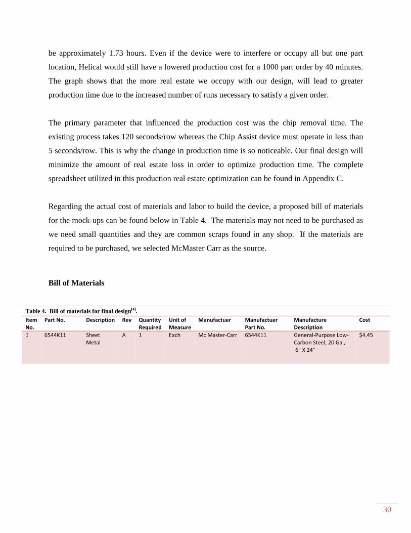
Regarding the actual cost of materials and labor to build the device, a proposed bill of materials
for the mock-ups can be found below in Table 4. The materials may not need to be purchased as
we need small quantities and they are common scraps found in any shop. If the materials are
required to be purchased, we selected McMaster Carr as the source.
Bill of Materials
Table 4. Bill of materials for final design[4]. Item
No.
Part No. Description Rev Quantity
Required
Unit of
Measure
Manufactuer Manufactuer
Part No.
Manufacture
Description
Cost
1 6544K11 Sheet
Metal
A 1 Each Mc Master-Carr 6544K11 General-Purpose Low-
Carbon Steel, 20 Ga ,
6" X 24"
$4.45
31
Chapter 5 Product Realization
The final prototype chip removal device was manufactured by using two basic sheet metal
forming tools, a sheet metal shear and sheet metal break. The sheet metal shear was used to cut
down the sheet metal to the proper length and width before the bends were put in place. The
break was used to create the four bends in the sheet metal. Bend placement and bend angles were
the most important aspects of manufacturing our final design. Since the chip removal device is
used in CNC machinery repeatability is very important to ensure that the cleaning device
operates seamlessly with the current tooling in place at Helical. The entrance angle of the chip
removal device was created using hand held sheet metal shears.
With limitations to the manufacturing processes that we could use to construct the final
prototype, the bend angles and entrance reliefs may differ from our planned design. The sheet
metal shear and sheet metal brake are both manual sheet metal forming tools. We recommend
that Helical uses CNC sheet metal shear and CNC controlled sheet metal press break. By using
computer numerically controlled sheet metal forming tools, the bend placement and angles can
have higher tolerances and better repeatability for future chip removal devices.
32
Chapter 6 Design Verification Plan
Test Descriptions
The following are short descriptions which portray the characteristics of each test method. These
testing methods are referenced in the Design Verification Plan and Report which is Table 5.
Test 1 - Chip Removal Effectiveness, Manual
Pass/Fail test that will determine the effectiveness of the three initial prototypes. This test
will be conducted at Helical on a Fanuc Robodrill. The test will include manually
inserting the chip removal device into the CNC machinery and attempting to remove chip
buildup from the drill bit. This test will be used for design validation of the first three
prototypes that are to be constructed by Chip Assist.
Test 2 - No Interference with Existing Machinery
Pass/Fail test that will be used to verify that chip removal device will not interfere with
any of the current CNC machinery that the device will be integrated with. This test will
be performed using a Computer-Aided Manufacturing Software (CAM) that will verify
that the chip removal device will not damage CNC machinery or products and ensure that
the device will be integrated with the CNC control that operates the Fanuc Robodrill.
Test 3 - Cycle Time
Test will verify that the cleaning cycle time for each row of machined parts will be less
than five seconds maximum. The cycle time test will be preformed after the chip removal
device has passed test 2, the no interference with existing machinery test. This test will be
performed at Helical Products on a Fanuc Robodrill machining an empty pallet. This test
is a design validation test with an acceptance criterion of the cycle time being less than
five seconds.
Test 4 - Chip Removal Effectiveness, CNC
Pass/Fail test that will determine the effectiveness of the final chip removal prototype.
This test will be conducted at Helical on a Fanuc Robodrill on a complete pallet of 0.75”
diameter parts. The test will include integrating the chip removal device into the CNC
machinery and attempting to automatically remove chip buildup from the drill bit. This

33
test will be used for design validation of the final prototype design. Test will verify the
design requirements that the device must remove the chip build from the drill bits,
operate automatically, and integrate with the current CNC control.
Test 5 - Accommodation of Different Drill Sizes
Pass/Fail test that will verify that the chip removal device will accommodate drills of
jobber length from #56 to 3/8. The test is a repeated test of automatic chip removal
effectiveness. This test will be conducted at Helical on a Fanuc Robodrill on a complete
pallet of parts. For each run the parts will be varied in size each run to ensure that all drill
sizes are tested in the final chip removal device.
Setup
The final chip removal device was delivered to Helical at the end of Spring Quarter. The device
was coated with paint to help prevent any possibilities of corrosion while in use. Helical also
created a device with the desired dimensions, but used stainless steel. With the assistance of
Alex, a G-Code program was created which would allow for the working tool to enter the device
and then rise and removing the chip buildup. This program was separate from the machining
program. The cleaning program would need to be implemented in every CNC machine that
would utilize the chip removal device. The cleaning program created was initially used on the
Fanuc Robodrill. Minor modification to the cleaning program would be required if Helical
wanted to use it on other CNC machines. Helical could now call upon this program at any point
during the machining process. The cleaning program lowers the tool needed for chip removal to
a height approximately ¼ inch from the chuck in reference to the top of the cleaning device.
Once in this starting position, the tool is inserted into the cleaning device by opening the jaws of
the device. The tool moves horizontally to approximately 2 inches into the device. At this
location the tool is then lifted from the device whit it rotates in reverse. From testing it was
noticed that chip buildup was easily removed when the drill bit was reversed.
34
Results
Helical utilized the chip removal devices throughout the summer in order to test its feasibility
and usability. Alex was contacted throughout the summer to get updates on the devices. Early
notification from Alex told us that devices looked very promising, but were not currently in use
due to production demands. Later in the summer Alex notified us that Helical were able to use
the devices in particular production runs. The chip assist devices worked every time they were
used. Alex was completely satisfied with the chip removal device; however there were two
minor issues that needed to be addressed. These two issues related to the entrance angle and the
device stiffness. When large tools entered the cleaning device, there was significant binding
between the cleaning device and tool due to the increases clamping force. The second issue deals
with torsional bending of the device when a tools cutting edge binds up the cleaning device.
35
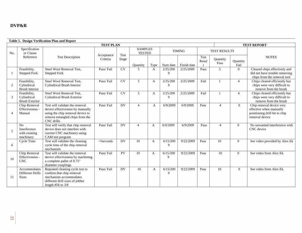
DVP&R
Table 5. Design Verification Plan and Report TEST PLAN TEST REPORT
No.
Specification or Clause Reference Test Description
Acceptance Criteria
Test Stage
SAMPLES TESTED
TIMING TEST RESULTS
NOTES
Quantity Type Start date Finish date
Test Resul
t
Quantity Pass
Quantity Fail
1 Feasibility, Stepped Fork
Steel Wool Removal Test, Stepped Fork
Pass/ Fail CV 5 A 2/25/2009
2/25/2009 Pass 5 0 Cleared chips effectively and did not have trouble removing chips from the removal tool
2 Feasibility, Cylindrical Brush Interior
Steel Wool Removal Test, Cylindrical Brush Interior
Pass/ Fail CV 5 A 2/25/2009
2/25/2009 Fail 1 4 Chips cleared efficiently but chips were very difficult to
remove from the brush
3 Feasibility, Cylindrical Brush Exterior
Steel Wool Removal Test, Cylindrical Brush Exterior
Pass/ Fail CV 5 A 2/25/2009
2/25/2009 Fail 1 4 Chips cleared efficiently but chips were very difficult to
remove from the brush
4
Chip Removal Effectiveness - Manual
Test will validate the removal device effectiveness by manually using the chip removal device to remove entangled chips from the CNC drills
Pass/ Fail DV 4 A 6/9/2009 6/9/2009 Pass 4 0 Chip removal device very effective when manually positioning drill bit to chip removal device
5
No Interference with existing machinery
Test will verify that chip removal device does not interfere with current CNC machinery using CAM test program
Pass/ Fail DV 4 A 6/9/2009 6/9/2009 Pass 4 0 No unwanted interference with CNC device
6 Cycle Time Test will validate the cleaning
cycle time of the chip removal mechanism
<5seconds DV 10 A 6/15/2009
9/22/2009 Pass 10 0 See video provided by Alex Ek
10
Chip Removal Effectiveness - CNC
Test will validate the removal device effectiveness by machining a complete pallet of 0.75" diameter couplings
Pass/ Fail PV 10 A 6/15/2009
9/22/2009
Pass 10 0 See video from Alex Ek
11
Accommodates Different Drills Sizes
Repeated cleaning cycle test to confirm that chip removal mechanism accommodates different drill sizes of jobber length #56 to 3/8
Pass/ Fail DV 10 A 6/15/2009
9/22/2009
Pass 10 0 See video from Alex Ek
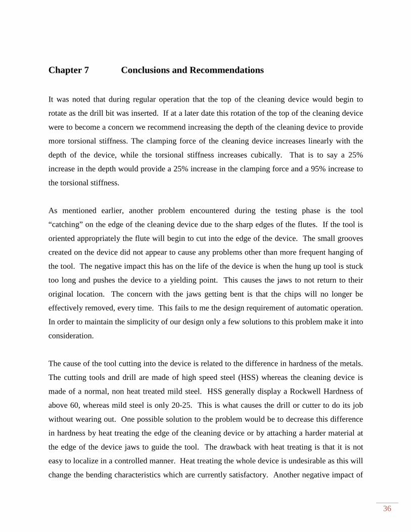
36
Chapter 7 Conclusions and Recommendations
It was noted that during regular operation that the top of the cleaning device would begin to
rotate as the drill bit was inserted. If at a later date this rotation of the top of the cleaning device
were to become a concern we recommend increasing the depth of the cleaning device to provide
more torsional stiffness. The clamping force of the cleaning device increases linearly with the
depth of the device, while the torsional stiffness increases cubically. That is to say a 25%
increase in the depth would provide a 25% increase in the clamping force and a 95% increase to
the torsional stiffness.
As mentioned earlier, another problem encountered during the testing phase is the tool
“catching” on the edge of the cleaning device due to the sharp edges of the flutes. If the tool is
oriented appropriately the flute will begin to cut into the edge of the device. The small grooves
created on the device did not appear to cause any problems other than more frequent hanging of
the tool. The negative impact this has on the life of the device is when the hung up tool is stuck
too long and pushes the device to a yielding point. This causes the jaws to not return to their
original location. The concern with the jaws getting bent is that the chips will no longer be
effectively removed, every time. This fails to me the design requirement of automatic operation.
In order to maintain the simplicity of our design only a few solutions to this problem make it into
consideration.
The cause of the tool cutting into the device is related to the difference in hardness of the metals.
The cutting tools and drill are made of high speed steel (HSS) whereas the cleaning device is
made of a normal, non heat treated mild steel. HSS generally display a Rockwell Hardness of
above 60, whereas mild steel is only 20-25. This is what causes the drill or cutter to do its job
without wearing out. One possible solution to the problem would be to decrease this difference
in hardness by heat treating the edge of the cleaning device or by attaching a harder material at
the edge of the device jaws to guide the tool. The drawback with heat treating is that it is not
easy to localize in a controlled manner. Heat treating the whole device is undesirable as this will
change the bending characteristics which are currently satisfactory. Another negative impact of

37
a device with a harder edge is increased wear on the tool’s cutting edge. As the tool is pulled out
of the device the edge of the flutes scrape the harder material which would cause increased wear
of the tool. Because this would increase the complexity of the manufacture of the device and
increase tool wear, it is not suggested that this solution be pursued.
Instead of modifying the Chip Assist to mitigate the catching problem, it is proposed that the
machine code be changed to prevent this. If the tool spindle is run in a slow reverse speed, the
cutting edge of the tool would not be able to cut into the Chip Assist upon entry. This is a
minimal cost solution that requires no design changes to the device.

38
References
1. Agapiou, John S., and David A. Stephenson. Metal Cutting Theory and Practice. New York:
C R C P LLC, 2005. Pg. 219.
2. "Pallet-Changer System offers repeatability of 0.0002 in., Methods Machine Tools, In." The
complete source for the latest industrial news solutions. 18 Feb. 2009
<http://news.thomasnet.com/fullstory/464262>.
3. "EMUGE - Press Releases > Emuge Solid Carbide Thread Mill Series Offers Increased
Efficiency, High-Confidence Machining." EMUGE - The leader in thread cutting technology
and performance. 28 Jan. 2009
<http://www.emuge.com/news_events/solid_carbide_threadmill_11_8.html>.
4. McMaster-Carr. 13 Mar. 2009 <http://www.mcmaster.com/#>.
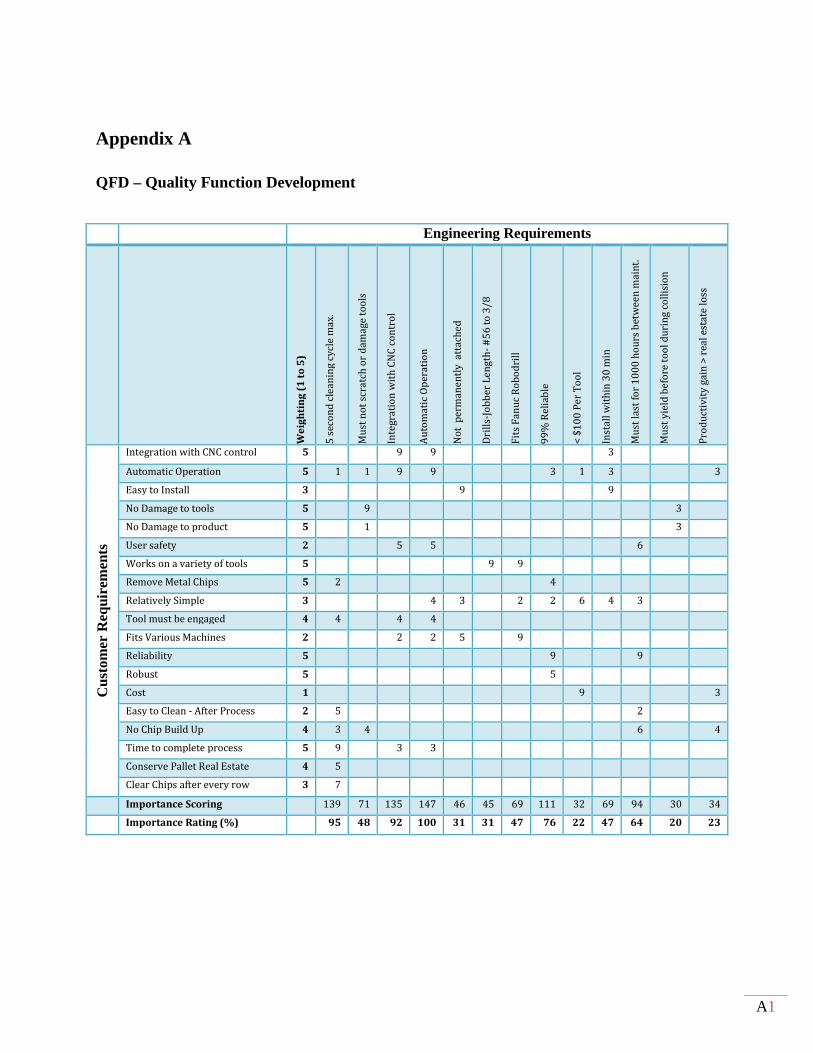
A1
Appendix A
QFD – Quality Function Development
Engineering Requirements
We
igh
tin
g (
1 t
o 5
)
5 s
eco
nd
cle
an
ing
cy
cle
ma
x.
Mu
st n
ot
scra
tch
or
dam
age
to
ols
Inte
gra
tio
n w
ith
CN
C c
on
tro
l
Au
tom
ati
c O
per
atio
n
No
t p
erm
an
en
tly
att
ach
ed
Dri
lls-
Job
ber
Le
ng
th-
#5
6 t
o 3
/8
Fit
s F
an
uc
Ro
bo
dri
ll
99
% R
eli
able
< $
10
0 P
er
To
ol
Inst
all
wit
hin
30
min
Mu
st l
ast
for
10
00
ho
urs
bet
we
en
ma
int.
Mu
st y
ield
be
fore
to
ol
du
rin
g c
oll
isio
n
Pro
du
ctiv
ity
gai
n >
rea
l es
tate
lo
ss
Cus
tom
er R
equi
rem
ents
Integration with CNC control 5 9 9 3
Automatic Operation 5 1 1 9 9 3 1 3 3
Easy to Install 3 9 9
No Damage to tools 5 9 3
No Damage to product 5 1 3
User safety 2 5 5 6
Works on a variety of tools 5 9 9
Remove Metal Chips 5 2 4
Relatively Simple 3 4 3 2 2 6 4 3
Tool must be engaged 4 4 4 4
Fits Various Machines 2 2 2 5 9
Reliability 5 9 9
Robust 5 5
Cost 1 9 3
Easy to Clean - After Process 2 5 2
No Chip Build Up 4 3 4 6 4
Time to complete process 5 9 3 3
Conserve Pallet Real Estate 4 5
Clear Chips after every row 3 7
Importance Scoring 139 71 135 147 46 45 69 111 32 69 94 30 34
Importance Rating (%) 95 48 92 100 31 31 47 76 22 47 64 20 23
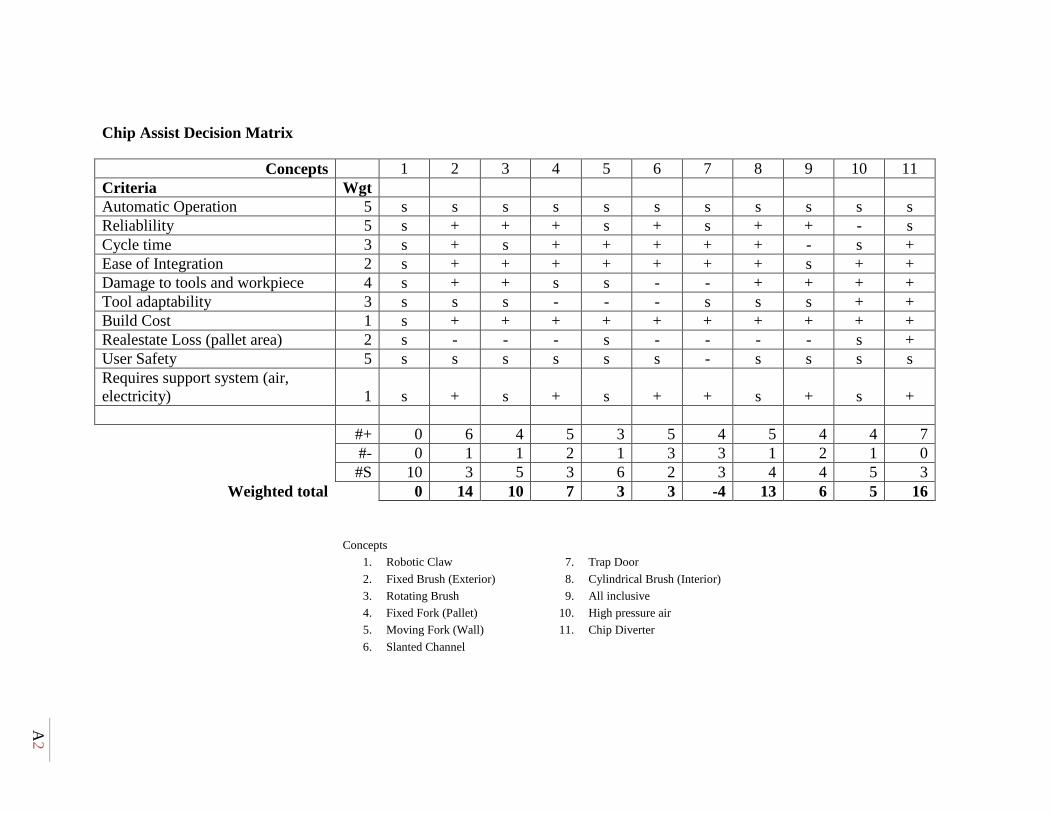
A2
Chip Assist Decision Matrix
Concepts 1 2 3 4 5 6 7 8 9 10 11 Criteria Wgt Automatic Operation 5 s s s s s s s s s s s Reliablility 5 s + + + s + s + + - s Cycle time 3 s + s + + + + + - s + Ease of Integration 2 s + + + + + + + s + + Damage to tools and workpiece 4 s + + s s - - + + + + Tool adaptability 3 s s s - - - s s s + + Build Cost 1 s + + + + + + + + + + Realestate Loss (pallet area) 2 s - - - s - - - - s + User Safety 5 s s s s s s - s s s s Requires support system (air, electricity) 1 s + s + s + + s + s +
#+ 0 6 4 5 3 5 4 5 4 4 7 #- 0 1 1 2 1 3 3 1 2 1 0 #S 10 3 5 3 6 2 3 4 4 5 3
Weighted total 0 14 10 7 3 3 -4 13 6 5 16
Concepts
1. Robotic Claw 7. Trap Door
2. Fixed Brush (Exterior) 8. Cylindrical Brush (Interior)
3. Rotating Brush 9. All inclusive
4. Fixed Fork (Pallet) 10. High pressure air
5. Moving Fork (Wall) 11. Chip Diverter
6. Slanted Channel
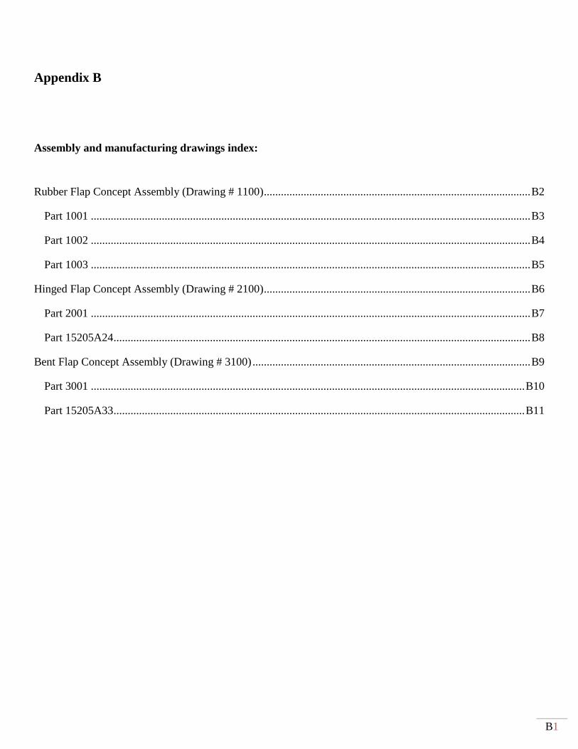
B1
Appendix B
Assembly and manufacturing drawings index:
Rubber Flap Concept Assembly (Drawing # 1100) .............................................................................................. B2
Part 1001 ........................................................................................................................................................... B3
Part 1002 ........................................................................................................................................................... B4
Part 1003 ........................................................................................................................................................... B5
Hinged Flap Concept Assembly (Drawing # 2100) .............................................................................................. B6
Part 2001 ........................................................................................................................................................... B7
Part 15205A24 ................................................................................................................................................... B8
Bent Flap Concept Assembly (Drawing # 3100) .................................................................................................. B9
Part 3001 ......................................................................................................................................................... B10
Part 15205A33 ................................................................................................................................................. B11
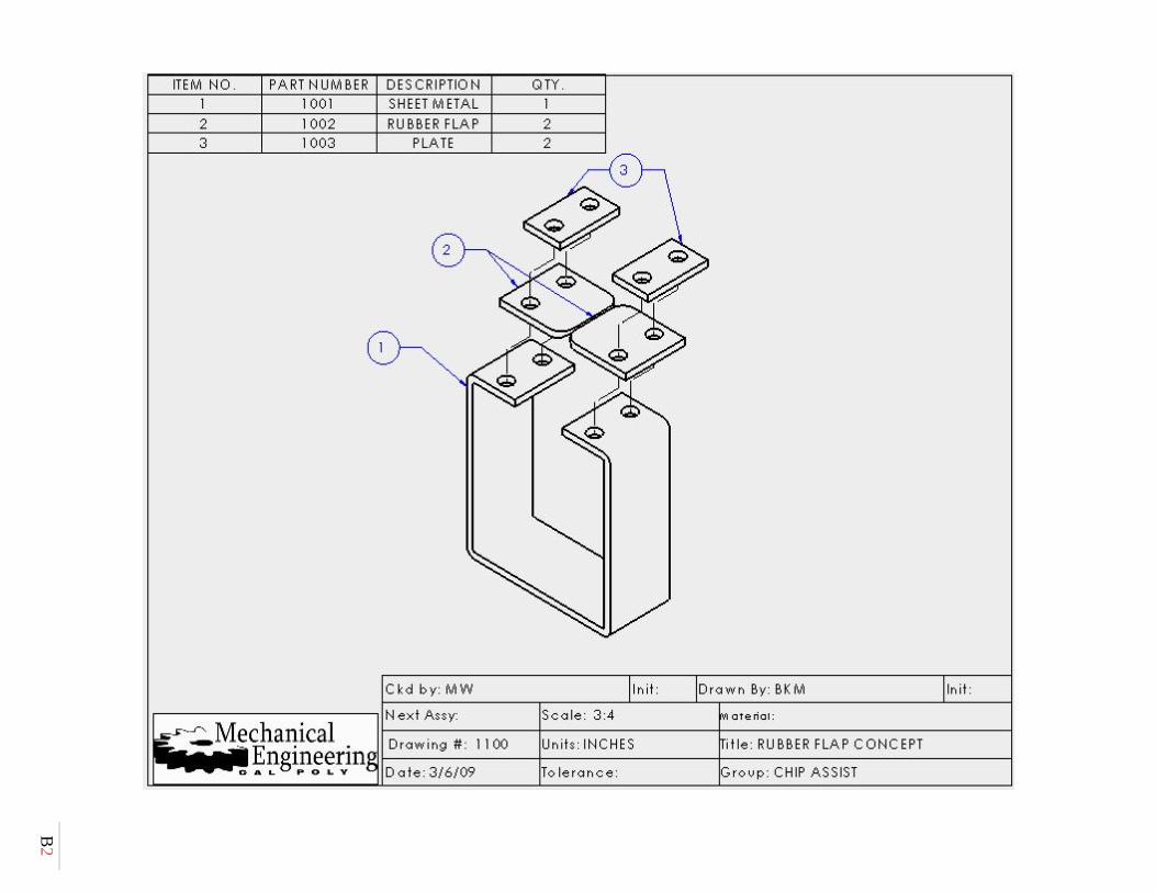
B2
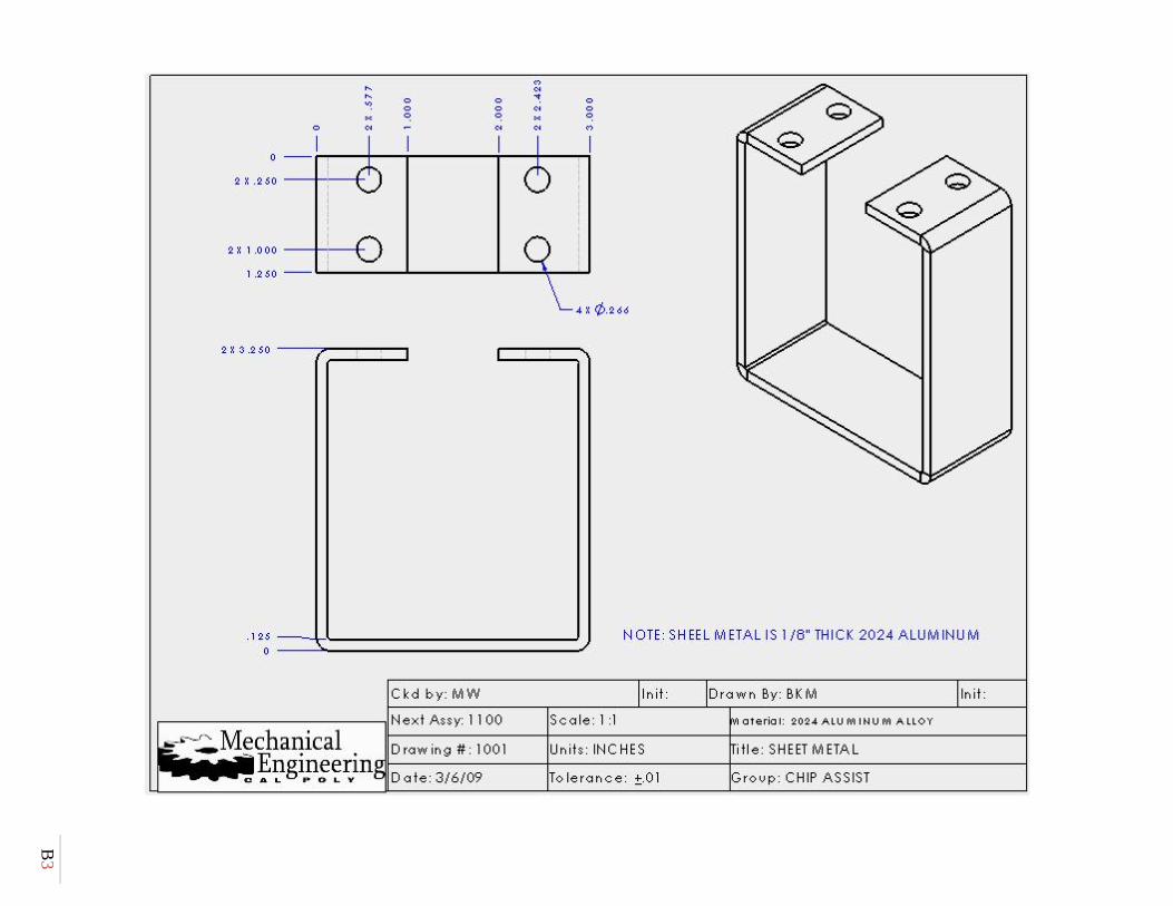
B3

B4
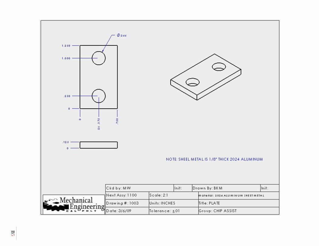
B5
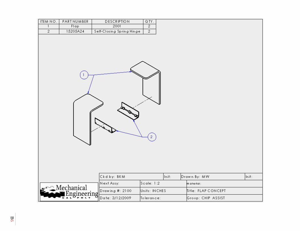
B6
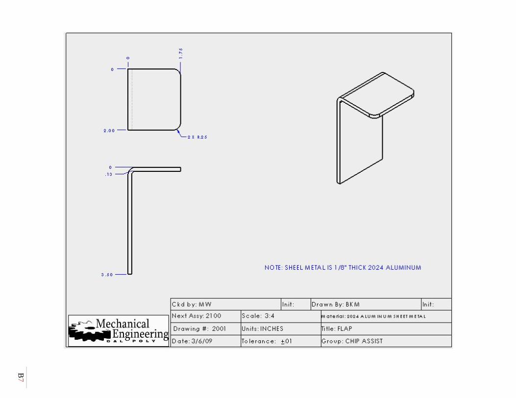
B7
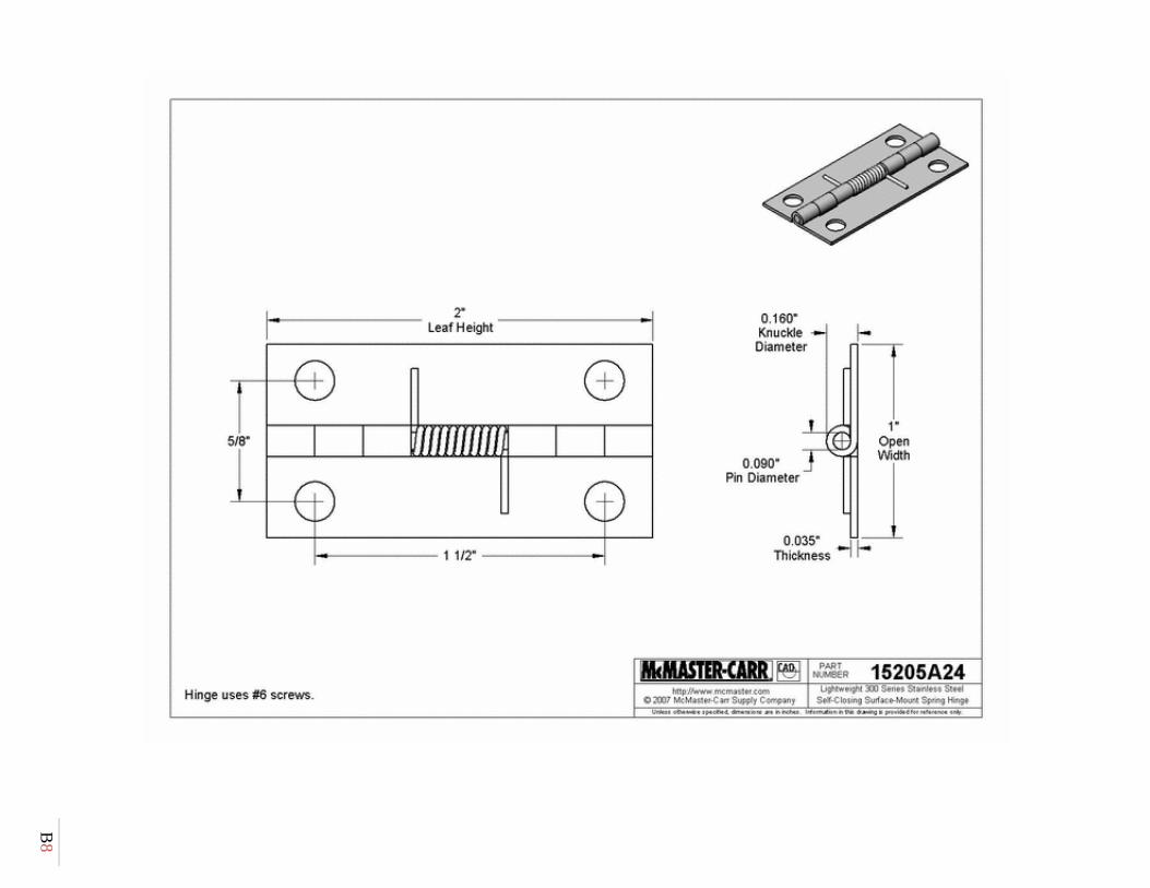
B8
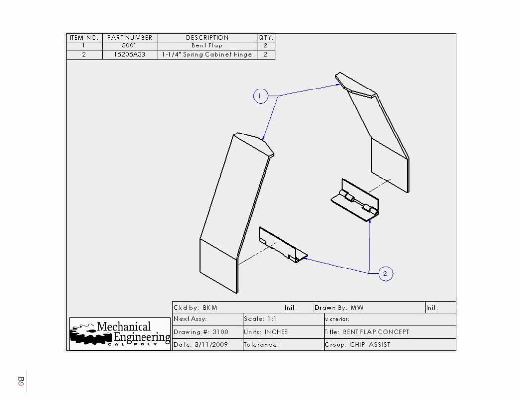
B9
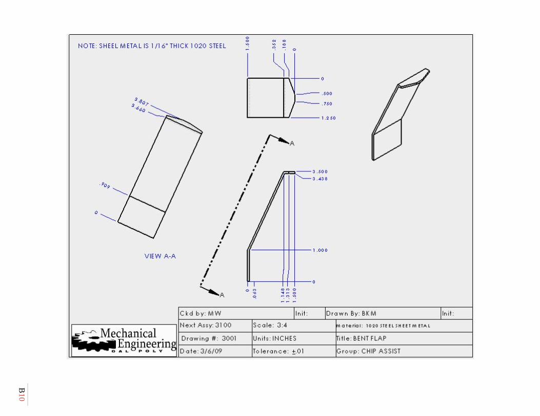
B10

B11
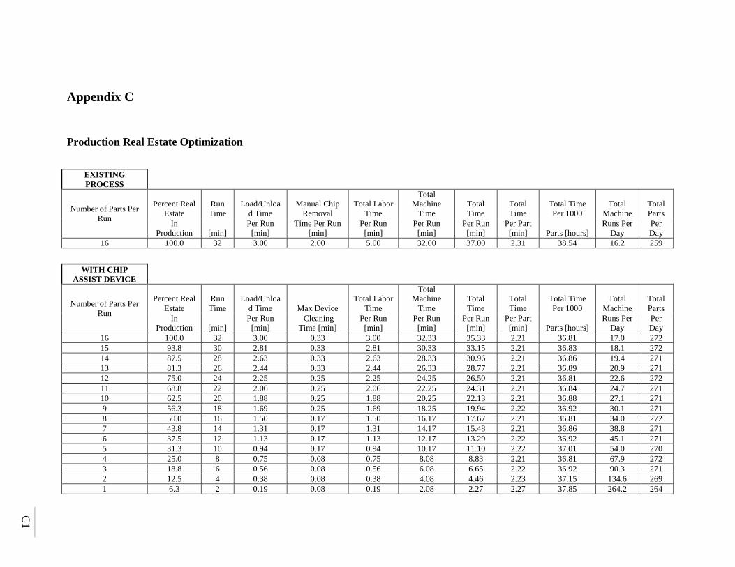
C1
Appendix C
Production Real Estate Optimization
EXISTING PROCESS
Number of Parts Per Run
Percent Real Estate
Run Time
Load/Unload Time
Manual Chip Removal
Total Labor Time
Total Machine
Time Total Time
Total Time
Total Time Per 1000
Total Machine
Total Parts
In Production [min]
Per Run [min]
Time Per Run [min]
Per Run [min]
Per Run [min]
Per Run [min]
Per Part [min] Parts [hours]
Runs Per Day
Per Day
16 100.0 32 3.00 2.00 5.00 32.00 37.00 2.31 38.54 16.2 259
WITH CHIP ASSIST DEVICE
Number of Parts Per Run
Percent Real Estate
Run Time
Load/Unload Time Max Device
Total Labor Time
Total Machine
Time Total Time
Total Time
Total Time Per 1000
Total Machine
Total Parts
In Production [min]
Per Run [min]
Cleaning Time [min]
Per Run [min]
Per Run [min]
Per Run [min]
Per Part [min] Parts [hours]
Runs Per Day
Per Day
16 100.0 32 3.00 0.33 3.00 32.33 35.33 2.21 36.81 17.0 272 15 93.8 30 2.81 0.33 2.81 30.33 33.15 2.21 36.83 18.1 272 14 87.5 28 2.63 0.33 2.63 28.33 30.96 2.21 36.86 19.4 271 13 81.3 26 2.44 0.33 2.44 26.33 28.77 2.21 36.89 20.9 271 12 75.0 24 2.25 0.25 2.25 24.25 26.50 2.21 36.81 22.6 272 11 68.8 22 2.06 0.25 2.06 22.25 24.31 2.21 36.84 24.7 271 10 62.5 20 1.88 0.25 1.88 20.25 22.13 2.21 36.88 27.1 271 9 56.3 18 1.69 0.25 1.69 18.25 19.94 2.22 36.92 30.1 271 8 50.0 16 1.50 0.17 1.50 16.17 17.67 2.21 36.81 34.0 272 7 43.8 14 1.31 0.17 1.31 14.17 15.48 2.21 36.86 38.8 271 6 37.5 12 1.13 0.17 1.13 12.17 13.29 2.22 36.92 45.1 271 5 31.3 10 0.94 0.17 0.94 10.17 11.10 2.22 37.01 54.0 270 4 25.0 8 0.75 0.08 0.75 8.08 8.83 2.21 36.81 67.9 272 3 18.8 6 0.56 0.08 0.56 6.08 6.65 2.22 36.92 90.3 271 2 12.5 4 0.38 0.08 0.38 4.08 4.46 2.23 37.15 134.6 269 1 6.3 2 0.19 0.08 0.19 2.08 2.27 2.27 37.85 264.2 264
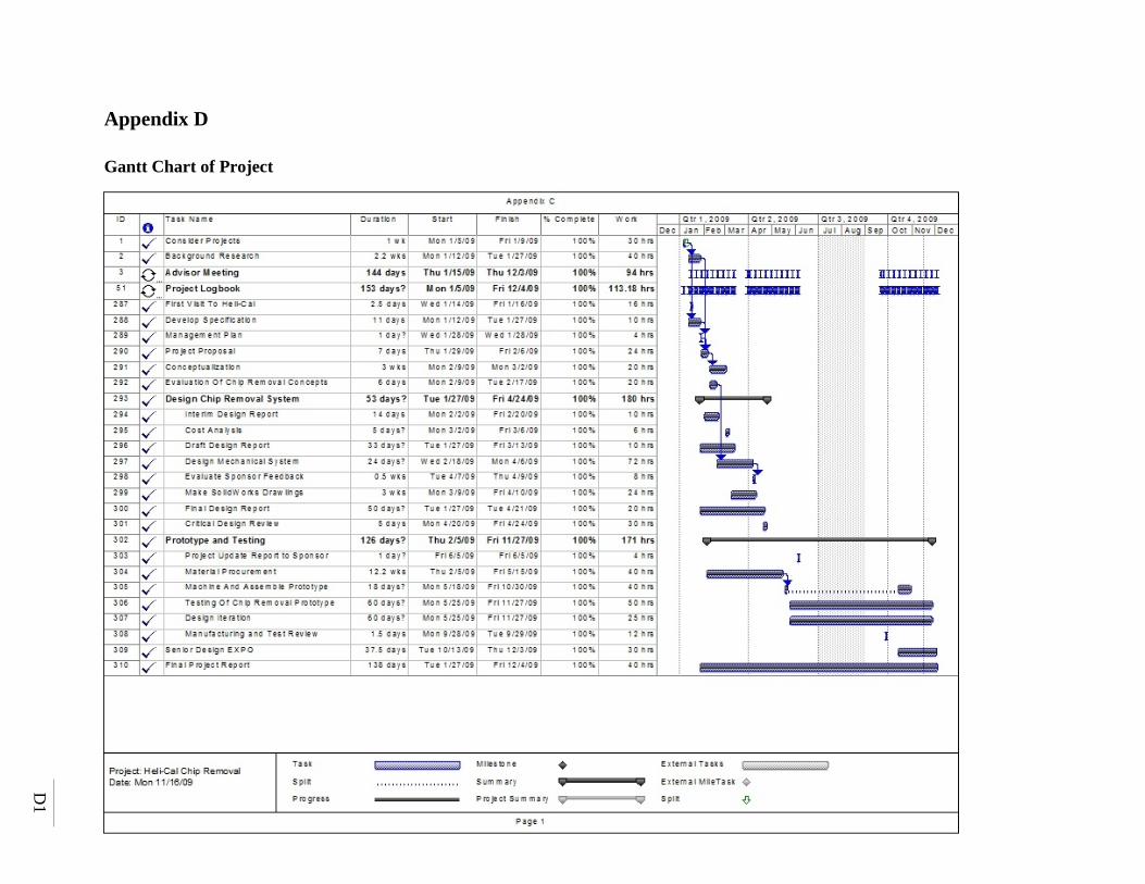
D1
Appendix D
Gantt Chart of Project

E1
Appendix E
Testing Data Sheet
Chip Assist - Metal Chip Removal Testing Verification Chips Removed Date
Manufacturing Operation Yes No
Cycle Time Comments
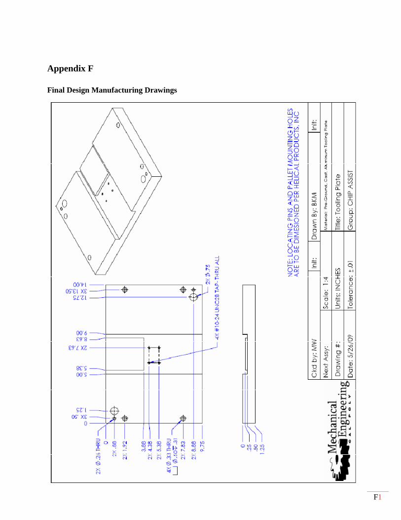
F1
Appendix F
Final Design Manufacturing Drawings

F2