deformation, yield and fracture of elastomer-modified polypropylene
TRANSCRIPT
Deformation, Yield and Fracture of Elastomer-ModifiedPolypropylene
S. M. Zebarjad,1 R. Bagheri,1 S. M. Seyed Reihani,1 A. Lazzeri2
1Department of Materials Science and Engineering, Sharif University of Technology, Azadi Avenue,14584, Tehran, Iran2Center for Materials Engineering, University of Pisa, Via Diotisalvi 2, 56126 Pisa, Italy
Received 27 February 2002; accepted 14 February 2003
ABSTRACT: In recent decades, great attention has beendevoted to the toughening of isotactic poly(propylene) (PP)with elastomers such as ethylene–propylene rubber (EPR).The most important reasons for this interest are the moder-ate cost and favorable properties of PP. This article is fo-cused on the role of EPR in the deformation and fracturemechanism of PP/EPR blends with different volume frac-tions of elastomer phase. Differential scanning calorimetry(DSC), tensile tests, and microscopy techniques were used inthis study. The fracture mechanism of isotactic PP tough-ened by EPR (PP/EPR) has also been studied by three pointbending (3-PB) and four point bending (4-PB) tests. Rubberparticle cavitation appears to be the main mechanism ofmicrovoid formation, although some matrix/particledebonding was observed. The investigation of the toughen-
ing mechanism shows that a wide damage zone spreads infront of the pre-crack. Optical microscopy (OM) illustratesthat, in pure PP, crazing is the only fracture mechanism, andno evidence of shear yielding is found, while in PP blendscraze-like features associated with shear yielding are ob-served, which have been identified as high shear localizeddilatational bands. This type of deformation pattern sup-ports a model previously proposed by Lazzeri1 to explainthe interparticle distance effect on the basis of the stabiliza-tion effect on dilatational band propagation exerted bystretched rubber particles. © 2003 Wiley Periodicals, Inc. J ApplPolym Sci 90: 3767–3779, 2003
Key words: poly(propylene) (PP); elastomers; toughness;mechanical properties; particle size distribution
INTRODUCTION
The increasing market demand for moderately priced,recyclable engineering plastics has made poly(pro-pylene) (PP) an attractive candidate for numerous ap-plications. PP is produced in a wide variety of types,characterized by melt flow indices (MFI) ranging from0.3 to more than 1000 g/10min. In addition to the easeof processing by virtually all methods, including in-jection molding, blow molding, extrusion and thermo-forming, PP can be easily recycled.2-3 Nevertheless,because of the poor impact strength of pure PP, its usein automotive and other engineering applications isstill limited compared to its potential.
Rubber toughening is a well-established method ofimproving fracture toughness. Polypropylene is mostoften toughened by feeding ethylene into the reactornear the end of the polymerization, so that about 10vol % of ethylene–propylene copolymer is formed insitu. This ’copolymer’ grade of PP is in fact a rubber-toughened version of PP. Blending of rubbers suchas ethylene–propylene rubber (EPR), ethylene-pro-pylene-diene monomer rubber (EPDM), Styrene Buta-
diene Styrene (SBS), Styrene Ethylene Butadiene Sty-rene (SEBS), Polybutadiene (PB) or Polyisoprene (PiP)with PP homopolymer or copolymer grade can also becarried out in a batch mixer after polymerization tofurther improve the impact strength. PP/EPR blendshave applications in the automotive industry, includ-ing the manufacture of bumpers and dashboards.2-3
A recent paper reviewed several aspects of thetoughening of semicrystalline thermoplastics, includ-ing isotactic PP,4 and a specific review has been de-voted to the rubber toughening of PP.5 From thesereviews, it appears that the major theories explainingthe toughening mechanisms of these blends are mul-tiple crazing, shear-yielding, and the formation of mi-crovoids due to rubber cavitation or debonding fromthe matrix. Moreover, the factors affecting tougheningappear to be quite complicated, because the additionof a rubbery phase affects the nucleation of crystalsduring solidification from the melt.6 Therefore, thesetheories appear to be valid only in some cases whenthey are applied under relevant conditions, and nogeneral consensus on the subject been reached.
An aspect that remains under debate is the contro-versial critical interparticle distance effect proposedalmost twenty years ago by Wu.7 In fact, this conceptis strongly correlated to several critical processing pa-rameters, like the optimum particle size distributionand the morphological structure of the elastomer
Correspondence to: A. Lazzeri ([email protected]).
Journal of Applied Polymer Science, Vol. 90, 3767–3779 (2003)© 2003 Wiley Periodicals, Inc.
phase. These parameters play a crucial role in thedesign of new polymer blends and composites, par-ticularly in the selection of a surface treatment thatallows the formation of a suitable interface or inter-phase and determines the proper level of adhesion.
The study reported in this article is part of a largerseries devoted to the explanation of the mechanicalbehavior of complex mineral-filled, short-fiber rein-forced and rubber-toughened PP systems used in au-tomotive applications.8–10
In particular, the aim of this study is to furtherunderstand the role of rubber particles in deformationand fracture mechanism in PP/rubber. Furthermore,the question of the formation of high-shear localizeddilatational bands will be studied in relation to a pre-vious model that takes into account the load bearingcapability of rubber particles.
EXPERIMENTAL
Materials
A series of PP blends was used in this study. Pellets of‘copolymer’ grade PP containing 20 wt % EPR (corre-sponding to 20.8% by volume), with the trade nameHifax CA 35M, were obtained from the Montell com-pany (Ferrara, Italy). According to the manufacturer,the EPR phase contains 70 wt % ethylene. The averagesize of the EPR particles is about 3.5 �m, with biggerparticles measuring approximately 4–6 �m.
To produce pellets containing 16 wt % (16.62 vol %)and 8 wt % (8.34 vol %) rubber, the original blend wasdiluted with isotactic PP with a MFI of 8 (g/10 min)from Imam Khomeini Petrochemical Complex (tradename 080) and extruded in a Windsor SX-30 single-screw extruder (Windsor Machine & Stamping, Wind-sor, Ontario, Canada) at a screw speed of 60 rpm overa temperature range of 180–220°C.
Standard tensile specimens were made via injectionmolding. The temperature in the four successive zonesof the Mono-mat 80 injection molding equipment(Eckert & Ziegler GmbH, Weißenburg, Germany) wasincreased progressively along its length from 200 to230°C.
Tensile tests
Tensile tests were carried out according to ASTMD638 using an 1115 Instron tensile frame at a cross-head speed of 5 mm/min (corresponding to a strainrate of 0.03 s�1). A minimum of three samples permaterial was tested at room temperature. In order toinvestigate the dominant deformation mechanismduring tensile tests, the side surfaces of some sampleswere polished prior to the test to achieve a surfaceroughness of about 5 �m. After the desired degree ofdeformation was achieved, polished surfaces were
studied by means of optical and scanning electronmicroscopes. Also in order to clarify the mechanism ofdeformation, after testing, some samples were coldfractured in liquid nitrogen along the tensile direction.The new fracture surfaces were subsequently investi-gated by scanning electron microscopy (SEM).
Three-point bending test
An endemic problem when dealing with rubbertoughened polymers is that upon increasing rubbercontent, the materials become progressively tougher,and the conditions for linear elastic fracture mechanics(LEFM) are no longer met. So the original ‘copolymer’grade PP and the materials with lower rubber contentwere tested according to the 1990 testing protocolapproved by European Structural Integrity Society(ESIS) to obtain the plane strain fracture toughness,KIC.11 For the two blends with higher rubber content,J-testing was performed according to the ESIS proto-col,12 making use of a multispecimen technique tomeasure the J-resistance curves and the fracturetoughness, JIC (considered here to be equivalent to J0.2)at room temperature. The corresponding KIC value hasbeen calculated by using the following formula:
KIC � �E � JIC
where E is the Young’s modulus.All fracture toughness tests were carried using sin-
gle edge notched 3-point bending (SEN-3PB) geome-try, using a 1115 Instron tensile frame at a crossheadspeed of 1 mm/min. Pre-cracks were produced bymeans of a razor blade, which had been previouslychilled at low temperature.
Specimens for KIC testing were prepared accordingto the testing protocol: length (L) � 60 mm, width (W)� 12.7 mm, thickness (B) � 6 mm, span (S) � 50.8 andthe initial notch depth, (�0) � 6.0 mm. For JIC testing,the same sample dimensions were used.
To elucidate the behavior of samples during the test,the side surfaces of some samples (without pre-crack)were polished prior to testing. After some deforma-tion occurred, those surfaces were studied via opticaland SEM.
Four-point bending test
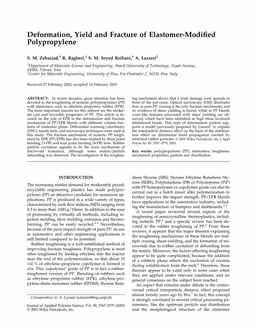
In order to observe the crack tip damage zone of PPand PP blends, the double edge-notched four pointbending (DEN-4PB) geometry was employed. For thistest, a 1115 Instron tensile frame was used at a cross-head speed of 1 mm/min. The sample thickness was 6mm. Other relevant geometrical parameters are re-ported in Figure 1. Details of this technique are asfollows. First, two edge cracks of equal length were
3768 ZEBARJAD ET AL.
introduced into the bending samples. In order to pro-tect the specimens from mechanical work after testing,the side surfaces of the samples were polished prior totesting to achieve a surface roughness of about 1 �m.Then each specimen was loaded into a four-pointbending fixture until damage zones formed near thecrack tips. Finally, one of the two cracks reached theinstability condition and propagated until the finalfracture of the sample. After completion of fracture,the other crack unloads, thus leaving a well-developeddamage zone that clearly represents the condition ofthe material just before failure. The surface of thedamage zone can be observed using optical and SEM.
To investigate the damage zone under plane straincondition, it would be necessary to observe the inte-rior of the samples by using transmission optical mi-croscopy (TOM). This can be achieved by thinning thesample to about 30–50 �m via petrographic polish-ing.13 The procedure used in this work, in which themicroscope examination is limited to the external sur-faces of the samples and thus plane stress regions arevisible, has two main advantages, however: (a) pro-tection of the specimen from mechanical damage dur-ing the thinning and polishing stages, and (b) relativeease of operation. Since this optical microscopy studyis complemented by SEM analysis of the fracture sur-face, the overall examination of the results can providean accurate picture of the fracture mechanism operat-ing in the materials under investigation.
Microscope evaluation
PM3 and BX60 Olympus optical microscopes wereemployed to examine the damage zone in tensile and
DN-4PB specimens, respectively, under reflective lightconditions. Also, an Olympus SZ40 optical microscopewas used to measure the stress whitening width. AJeol JSM-5600LV scanning electron microscope wasused to study the side surfaces of 3PB and 4PB barsand the fracture surfaces of selected samples. Thespecimens were coated, using an Edwards S150B sput-ter coater, with a thin layer of gold prior to microscopyto avoid charge build up.
Calorimetric analysis
Thermal properties were measured using a Perkin-Elmer DSC-2C differential scanning calorimeter. Theinstrument was calibrated by measuring the meltingtemperature of indium. All measurements were per-formed under nitrogen flow. The mass of the samplesused varied between 5 and 8 mg. During the firstheating run, which was performed at the rate of 10°C/min, the temperature range examined was from roomtemperature to somewhere higher than the meltingpoint of the samples. After reaching this temperature,the specimens were cooled at the same rate of 10°C/min. The second heating run was performed similarlyat the rate of 10°C/min. Temperatures and heats ofmelting (crystallization) were determined from themelting peaks and from the corresponding areas of thethermograms, respectively. The degree of crystallinitywas calculated from the heat of fusion, assuming avalue of 209 J/g as the enthalpy of fusion of a perfect(100%) isotactic PP crystal.14
RESULTS AND DISCUSSION
Thermal behavior
The melting behavior of pure PP and its blends issummarized in Table I. The results show that pure PPand PP blends exhibit an endothermic peak, indicatingthe absorption of heat during the melting process. Theamount of heat developed during the melting phase ofPP in the blend is almost independent of the rubbercontent. The degree of crystallinity of the PP phase inall blends is estimated to be about 50%. The increase ofcrystallization temperature with increase of rubber
Figure 1 Schematic of four-point bending test specimen.
TABLE IDSC Data
Rubbercontent(wt %)
Heating I Heating II Cooling
Tm (°C) �Hm (J/g PP) �Hm (J/g blend) Tm (°C) �Hm (J/g PP) �Hm (J/g blend) Tc (°C) �Hc (J/g)
0% 166.69 105.1 105.1 166.7 103.1 103.1 111.39 �109.18% 164.9 107.2 98.7 166.1 107.9 99.27 113.23 �94.816% 164.9 107.4 90.3 165.3 108.1 90.8 115.25 �91.820% 164.3 106.5 85.2 164.0 107.7 86.2 117.15 �90.2
DEFORMATION, YIELD, AND FRACTURE 3769
content can be attributed to the nucleation effect ofelastomer particles on PP crystallization, because theydecrease the average size of spherulites,15 encouragingPP fracture resistance.16
Tensile behavior
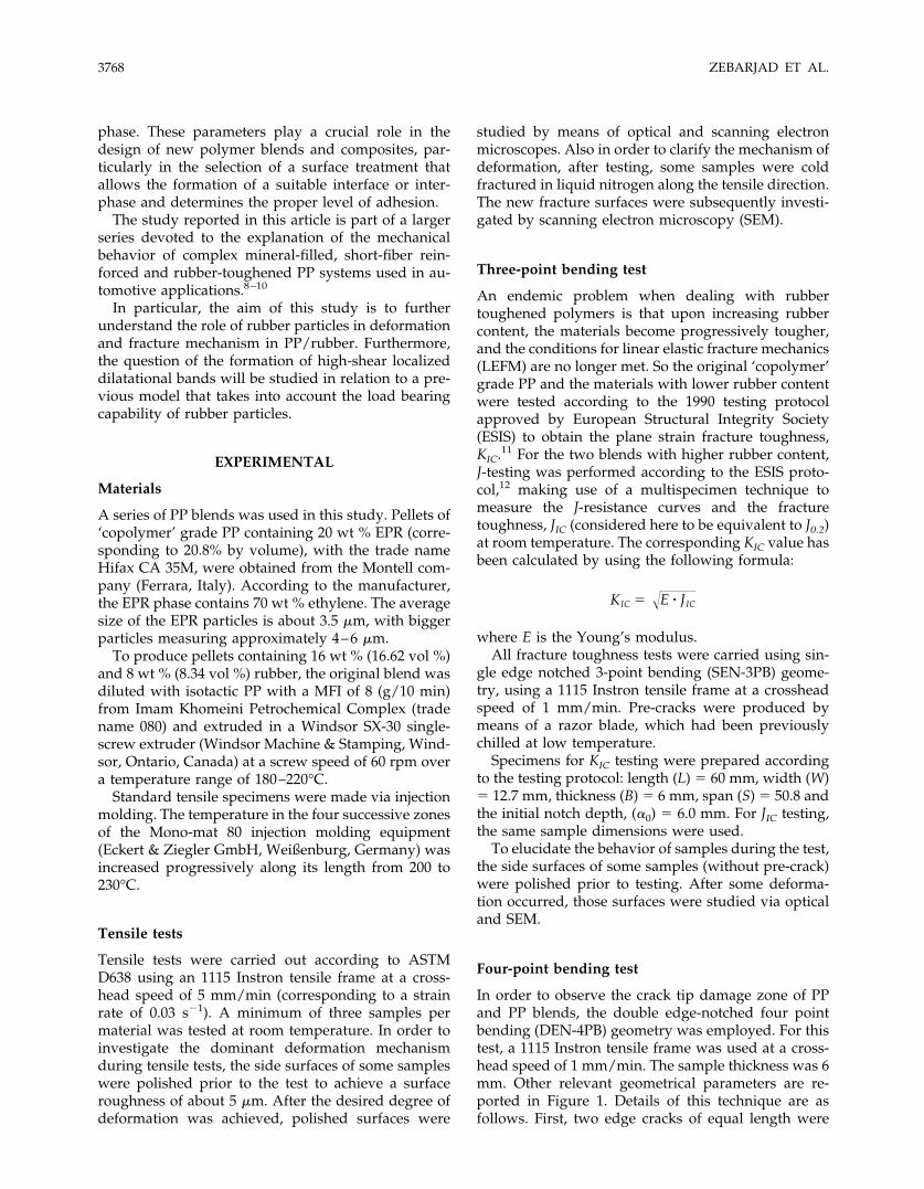
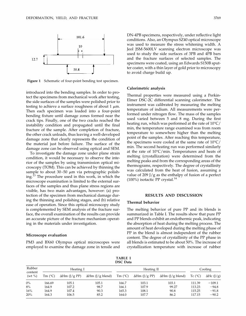
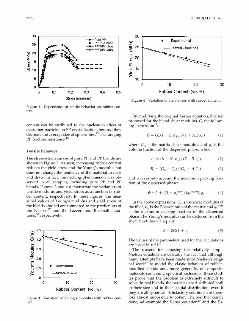
The stress–strain curves of pure PP and PP blends areshown in Figure 2. As seen, increasing rubber contentreduces the yield stress and the Young’s modulus butdoes not change the tendency of the material to neckand draw. In fact, the necking phenomenon was ob-served in all samples, including pure PP and PPblends. Figures 3 and 4 demonstrate the variations oftensile modulus and yield stress as a function of rub-ber content, respectively. In these figures, the mea-sured values of Young’s modulus and yield stress ofthe blends studied are compared to the predictions ofthe Nielsen17 and the Lazzeri and Bucknall equa-tions,18 respectively.
By modifying the original Kerner equation, Nielsenproposed for the blend shear modulus, G, the follow-ing expression17:
G � Gm�1 � Be��e�/�1 � AeBe�e� (1)
where Gm is the matrix shear modulus, and �e is thevolume fraction of the dispersed phase, while
Ae � �8 � 10 �m�/�7 � 5 �m� (2)
Be � �Gm � Ge�/�Gm � AeGe� (3)
and � takes into account the maximum packing frac-tion of the dispersed phase:
� � 1 � ��1 � �emax�/��e
�max�2���e (4)
In the above expressions, Ge is the shear modulus ofthe filler, �m is the Poisson ratio of the matrix and �e
max
is the maximum packing fraction of the dispersedphase. The Young’s modulus can be deduced from theshear modulus via eq. (5):
E � 2G�1 � �� (5)
The values of the parameters used for the calculationsare listed in ref.19.
The reasons for choosing the relatively simpleNielsen equation are basically the fact that althoughmany attempts have been made since Nielsen’s origi-nal work17 to model the elastic behavior of rubber-modified blends and, more generally, of compositematerials containing spherical inclusions, these stud-ies prove that the problem is extremely difficult tosolve. In real blends, the particles are distributed bothin their size and in their spatial distribution, even ifthey are all spherical. Satisfactory solutions are there-fore almost impossible to obtain. The best that can bedone, ad example the Reuss equation20 and the Es-
Figure 2 Dependence of tensile behavior on rubber con-tent.
Figure 3 Variation of Young’s modulus with rubber con-tent.
Figure 4 Variation of yield stress with rubber content.
3770 ZEBARJAD ET AL.
helby inclusion method of Chow,21 define just upperand lower bounds on the modulus. This is equally trueof modern work on modulus, based on finite-elementanalysis (FEA). These approaches work for regulararrays of identical spherical particles dispersed in acontinuous matrix, but not for real blends, with all oftheir irregularities. Good results from analytical ex-pressions or FEA require the exact concentration ofdispersed particles to be known and likewise theproperties of both phases to be known precisely. Theprecise determination of these parameters is beyondthe scope of this article, so the relatively unsophisti-cated Nielsen’s equation was considered reasonablefor a first approach analysis of the experimental data.Moreover, the modified Kerner’s equation is fre-quently used by workers in the field of mineral fillerreinforced polymers.20
Comparison of theoretical and experimental valuesof Young’s moduli show similar trends upon increas-ing the rubber content (Fig. 3). However, the theoret-ical expression underestimates the modulus data. Asdiscussed above, the Nielsen equation cannot take intoaccount important factors, such as particle size distri-bution and level of adhesion between matrix and rub-ber phase.
Regarding the yield stress of PP/EPR blends, ac-cording to Lazzeri and Bucknall18
Y � 0�1 � 1.375�e� (6)
where Y and 0 are the yield stresses of the blend andthe matrix, respectively, and �e is the volume fractionof the dispersed phase.
As seen in Figure 4, there is a good fit between theexperimental data and the suggested equation, on thebasis of their modified Gurson’s yield function byLazzeri-Bucknall,18 which was shown to fit very wellsome experimental data by Gloagen and coworkers22
and verified later by FEA.23 This is quite interesting,since this equation was derived from compression testresults, where particle cavitation does not occur.Lazzeri and Bucknall18 showed that, under the condi-tion of low triaxiality, there is only a small differencebetween the effect of non-cavitated particles and voidsand cavitated particles on the tensile yield stress, es-pecially at low volume fractions, those below 20%.
The reason both modulus and yield stress decreasewith increasing rubber content can be attributed to thefact that, since rubber particles have very low shearmodulus compared to PP, there is little or no stresstransfer from matrix to elastomer particles. Therefore,particles have almost the same effects as micro-voidson these mechanical properties.
Optical microscopy of deformed tensile bars
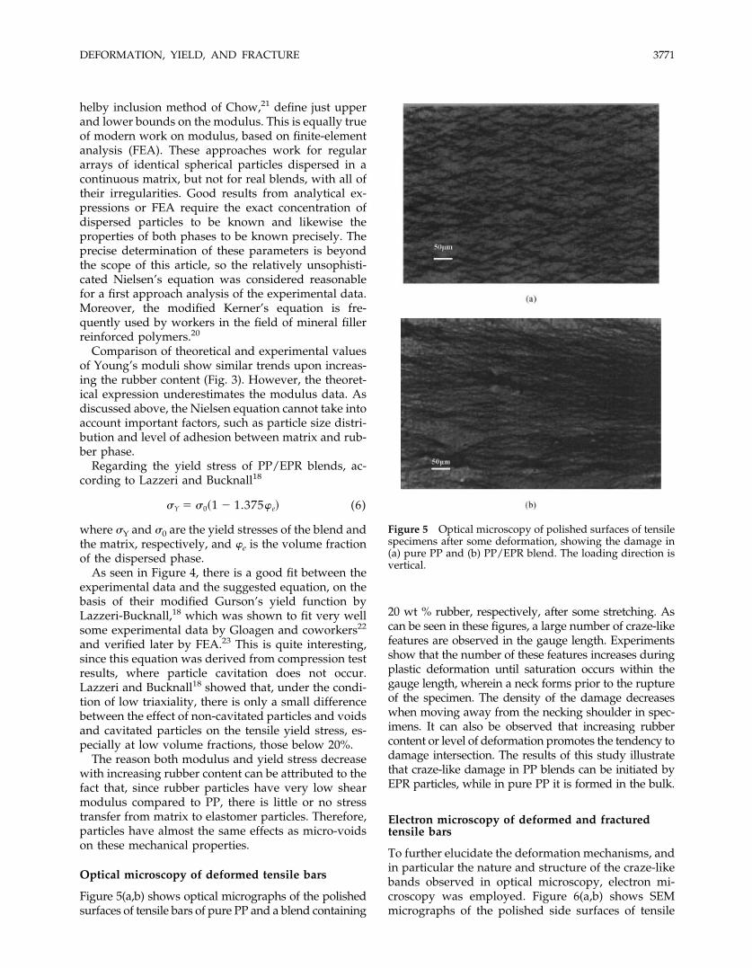
Figure 5(a,b) shows optical micrographs of the polishedsurfaces of tensile bars of pure PP and a blend containing
20 wt % rubber, respectively, after some stretching. Ascan be seen in these figures, a large number of craze-likefeatures are observed in the gauge length. Experimentsshow that the number of these features increases duringplastic deformation until saturation occurs within thegauge length, wherein a neck forms prior to the ruptureof the specimen. The density of the damage decreaseswhen moving away from the necking shoulder in spec-imens. It can also be observed that increasing rubbercontent or level of deformation promotes the tendency todamage intersection. The results of this study illustratethat craze-like damage in PP blends can be initiated byEPR particles, while in pure PP it is formed in the bulk.
Electron microscopy of deformed and fracturedtensile bars
To further elucidate the deformation mechanisms, andin particular the nature and structure of the craze-likebands observed in optical microscopy, electron mi-croscopy was employed. Figure 6(a,b) shows SEMmicrographs of the polished side surfaces of tensile
Figure 5 Optical microscopy of polished surfaces of tensilespecimens after some deformation, showing the damage in(a) pure PP and (b) PP/EPR blend. The loading direction isvertical.
DEFORMATION, YIELD, AND FRACTURE 3771
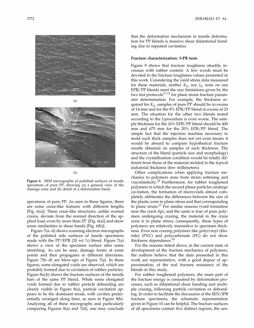
specimens of pure PP. As seen in these figures, thereare some craze-like features with different lengths[Fig. 6(a)]. These craze-like structures, unlike normalcrazes, deviate from the normal direction of the ap-plied load, even by more than 25° [Fig. 6(a)] and showsome similarities to shear bands [Fig. 6(b)].
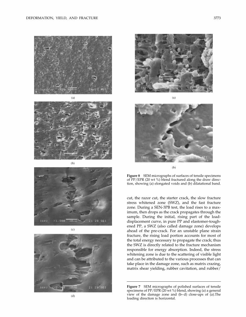
Figure 7(a–d) shows scanning electron micrographsof the polished side surfaces of tensile specimensmade with the PP/EPR (20 wt %) blend. Figure 7(a)shows a view of the specimen surface after somestretching. As can be seen, damage forms at somepoints and then propagates in different directions.Figure 7(b–d) are blow-ups of Figure 7(a). In thesefigures, some elongated voids are observed, which areprobably formed due to cavitation of rubber particles.Figure 8(a,b) shows the fracture surfaces of the tensilebars of the same PP blend.. While some elongatedvoids formed due to rubber particle debonding areclearly visible in Figure 8(a), particle cavitation ap-pears to be the dominant mode, with cavities prefer-entially arranged along lines, as seen in Figure 8(b).Analyzing all of these micrographs and particularlycomparing Figures 8(a) and 7(d), one may conclude
that the deformation mechanism in tensile deforma-tion for PP blends is massive shear dilatational band-ing due to repeated cavitation.
Fracture characterization: 3-PB tests
Figure 9 shows that fracture toughness steadily in-creases with rubber content. A few words must bedevoted to the fracture toughness values presented inthis work. Considering the yield stress data measuredfor these materials, neither KIC nor JIC tests on ourEPR/PP blends meet the size limitations given by thetwo test protocols11-12 for plane strain fracture param-eter determination. For example, the thickness re-quired for KIC samples of pure PP should be in excessof 14 mm and for the 8% EPR/PP blend in excess of 23mm. The situation for the other two blends testedaccording to the J-procedure is even worse. The sam-ple thickness for the 16% EPR/PP blend should be 400mm and 675 mm for the 20% EPR/PP blend. Thesimple fact that the injection machine necessary tomold such thick samples does not yet exist means itwould be absurd to compare hypothetical fractureresults obtained on samples of such thickness. Thestructure of the blend (particle size and morphology)and the crystallization condition would be totally dif-ferent from those of the material molded to the typicalindustrial thickness (few millimeters).
Other complications when applying fracture me-chanics to polymers arise from strain softening andviscoelasticity.24 Furthermore, for rubber toughenedpolymers in which the second phase particles undergocavitation, the formation of microvoids almost com-pletely obliterates the differences between the size ofthe plastic zone in plane stress and that correspondingto plane strain.23 For similar reasons (void formationnear the crack tip), and the same is true of pure poly-mers undergoing crazing, the material in the crazezone is in plane stress; consequently, these types ofpolymers are relatively insensitive to specimen thick-ness. Even non crazing polymers like poly(vinyl chlo-ride) (PVC) and polycarbonate (PC) do not showthickness dependence.24
For the reasons stated above, in the current state ofdevelopment of the fracture mechanics of polymers,the authors believe that the data presented in thiswork are representative, with a good degree of ap-proximation, of the real fracture resistance of theblends in this study.
For rubber toughened polymers, the main part ofthe fracture energy is consumed by deformation pro-cesses, such as dilatational shear banding and multi-ple crazing, following particle cavitation or debond-ing. In order to facilitate the discussion of the SEN-3PBfracture specimens, the schematic representationgiven in Figure 10 can be helpful. The fracture surfacesof all specimens contain five distinct regions, the saw
Figure 6 SEM micrographs of polished surfaces of tensilespecimens of pure PP, showing (a) a general view of thedamage zone and (b) detail of a deformation band.
3772 ZEBARJAD ET AL.
cut, the razor cut, the starter crack, the slow fracturestress whitened zone (SWZ), and the fast fracturezone. During a SEN-3PB test, the load rises to a max-imum, then drops as the crack propagates through thesample. During the initial, rising part of the load-displacement curve, in pure PP and elastomer-tough-ened PP, a SWZ (also called damage zone) developsahead of the pre-crack. For an unstable plane strainfracture, the rising load portion accounts for most ofthe total energy necessary to propagate the crack; thusthe SWZ is directly related to the fracture mechanismresponsible for energy absorption. Indeed, the stresswhitening zone is due to the scattering of visible lightand can be attributed to the various processes that cantake place in the damage zone, such as matrix crazing,matrix shear yielding, rubber cavitation, and rubber/
Figure 8 SEM micrographs of surfaces of tensile specimensof PP/EPR (20 wt %) blend fractured along the draw direc-tion, showing (a) elongated voids and (b) dilatational band.
Figure 7 SEM micrographs of polished surfaces of tensilespecimens of PP/EPR (20 wt %) blend, showing (a) a generalview of the damage zone and (b–d) close-ups of (a).Theloading direction is horizontal.
DEFORMATION, YIELD, AND FRACTURE 3773
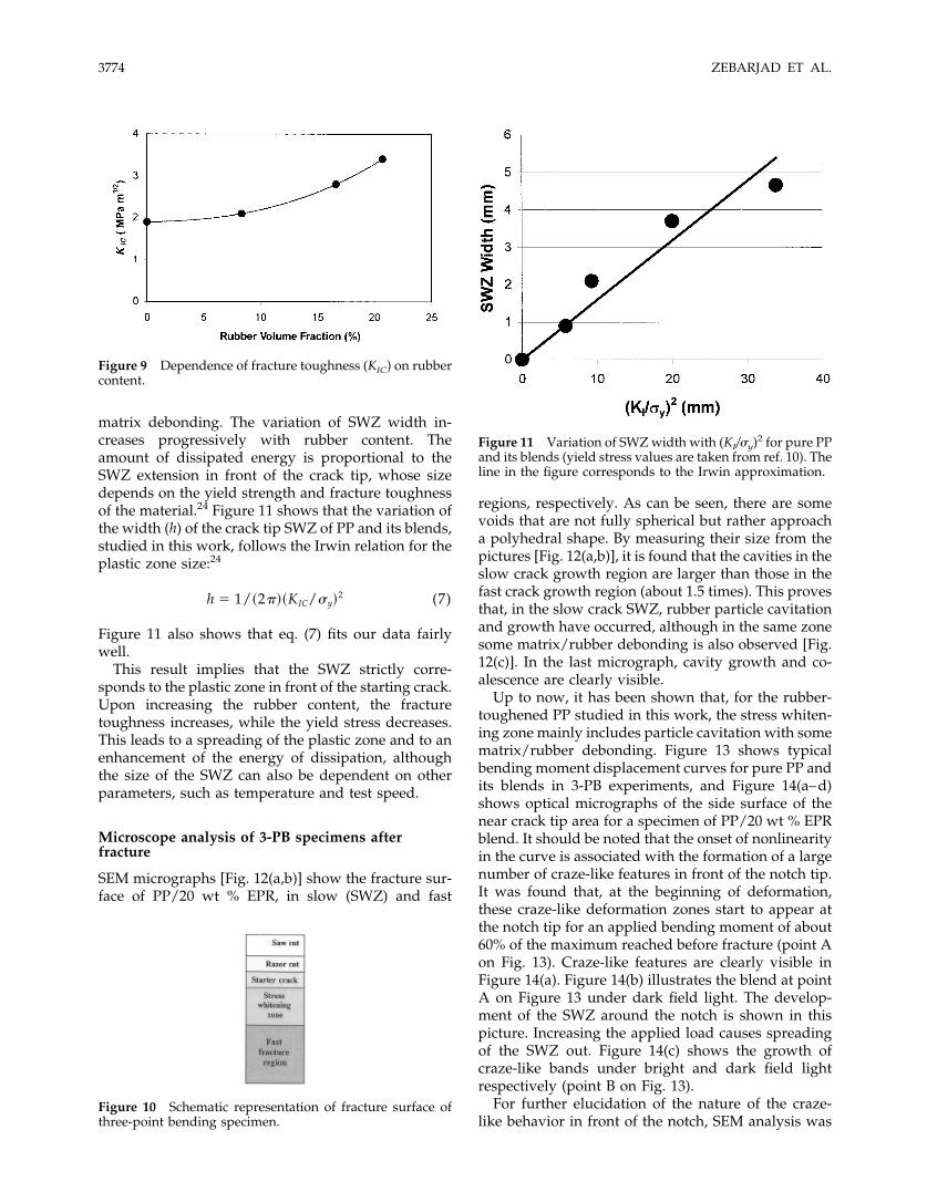
matrix debonding. The variation of SWZ width in-creases progressively with rubber content. Theamount of dissipated energy is proportional to theSWZ extension in front of the crack tip, whose sizedepends on the yield strength and fracture toughnessof the material.24 Figure 11 shows that the variation ofthe width (h) of the crack tip SWZ of PP and its blends,studied in this work, follows the Irwin relation for theplastic zone size:24
h � 1/�2��KIC/y�2 (7)
Figure 11 also shows that eq. (7) fits our data fairlywell.
This result implies that the SWZ strictly corre-sponds to the plastic zone in front of the starting crack.Upon increasing the rubber content, the fracturetoughness increases, while the yield stress decreases.This leads to a spreading of the plastic zone and to anenhancement of the energy of dissipation, althoughthe size of the SWZ can also be dependent on otherparameters, such as temperature and test speed.
Microscope analysis of 3-PB specimens afterfracture
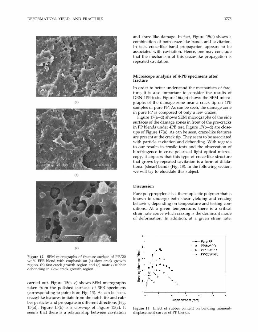
SEM micrographs [Fig. 12(a,b)] show the fracture sur-face of PP/20 wt % EPR, in slow (SWZ) and fast
regions, respectively. As can be seen, there are somevoids that are not fully spherical but rather approacha polyhedral shape. By measuring their size from thepictures [Fig. 12(a,b)], it is found that the cavities in theslow crack growth region are larger than those in thefast crack growth region (about 1.5 times). This provesthat, in the slow crack SWZ, rubber particle cavitationand growth have occurred, although in the same zonesome matrix/rubber debonding is also observed [Fig.12(c)]. In the last micrograph, cavity growth and co-alescence are clearly visible.
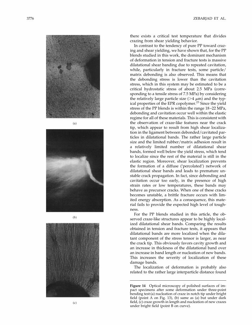
Up to now, it has been shown that, for the rubber-toughened PP studied in this work, the stress whiten-ing zone mainly includes particle cavitation with somematrix/rubber debonding. Figure 13 shows typicalbending moment displacement curves for pure PP andits blends in 3-PB experiments, and Figure 14(a–d)shows optical micrographs of the side surface of thenear crack tip area for a specimen of PP/20 wt % EPRblend. It should be noted that the onset of nonlinearityin the curve is associated with the formation of a largenumber of craze-like features in front of the notch tip.It was found that, at the beginning of deformation,these craze-like deformation zones start to appear atthe notch tip for an applied bending moment of about60% of the maximum reached before fracture (point Aon Fig. 13). Craze-like features are clearly visible inFigure 14(a). Figure 14(b) illustrates the blend at pointA on Figure 13 under dark field light. The develop-ment of the SWZ around the notch is shown in thispicture. Increasing the applied load causes spreadingof the SWZ out. Figure 14(c) shows the growth ofcraze-like bands under bright and dark field lightrespectively (point B on Fig. 13).
For further elucidation of the nature of the craze-like behavior in front of the notch, SEM analysis was
Figure 9 Dependence of fracture toughness (KIC) on rubbercontent.
Figure 10 Schematic representation of fracture surface ofthree-point bending specimen.
Figure 11 Variation of SWZ width with (KI/y)2 for pure PPand its blends (yield stress values are taken from ref. 10). Theline in the figure corresponds to the Irwin approximation.
3774 ZEBARJAD ET AL.
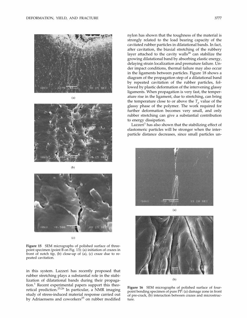
carried out. Figure 15(a–c) shows SEM micrographstaken from the polished surfaces of 3PB specimens(corresponding to point B on Fig. 13). As can be seen,craze-like features initiate from the notch tip and rub-ber particles and propagate in different directions [Fig.15(a)]. Figure 15(b) is a close-up of Figure 15(a). Itseems that there is a relationship between cavitation
and craze-like damage. In fact, Figure 15(c) shows acombination of both craze-like bands and cavitation.In fact, craze-like band propagation appears to beassociated with cavitation. Hence, one may concludethat the mechanism of this craze-like propagation isrepeated cavitation.
Microscope analysis of 4-PB specimens afterfracture
In order to better understand the mechanism of frac-ture, it is also important to consider the results ofDEN-4PB tests. Figure 16(a,b) shows the SEM micro-graphs of the damage zone near a crack tip on 4PBsamples of pure PP. As can be seen, the damage zonein pure PP is composed of only a few crazes.
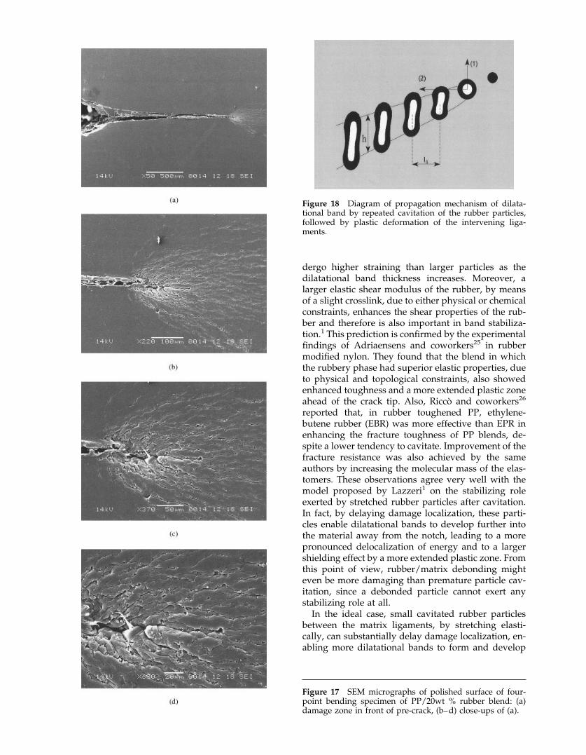
Figure 17(a–d) shows SEM micrographs of the sidesurfaces of the damage zones in front of the pre-cracksin PP blends under 4PB test. Figure 17(b–d) are close-ups of Figure 17(a). As can be seen, craze-like featuresare present at the crack tip. They seem to be associatedwith particle cavitation and debonding. With regardsto our results in tensile tests and the observation ofbirefringence in cross-polarized light optical micros-copy, it appears that this type of craze-like structurethat grows by repeated cavitation is a form of dilata-tional (shear) bands (Fig. 18). In the following section,we will try to elucidate this subject.
Discussion
Pure polypropylene is a thermoplastic polymer that isknown to undergo both shear yielding and crazingbehavior, depending on temperature and testing con-ditions. At a given temperature, there is a criticalstrain rate above which crazing is the dominant modeof deformation. In addition, at a given strain rate,
Figure 12 SEM micrographs of fracture surface of PP/20wt % EPR blend with emphasis on (a) slow crack growthregion, (b) fast crack growth region and (c) matrix/rubberdebonding in slow crack growth region.
Figure 13 Effect of rubber content on bending moment-displacement curves of PP blends.
DEFORMATION, YIELD, AND FRACTURE 3775
there exists a critical test temperature that dividescrazing from shear yielding behavior.
In contrast to the tendency of pure PP toward craz-ing and shear yielding, we have shown that, for the PPblends studied in this work, the dominant mechanismof deformation in tension and fracture tests is massivedilatational shear banding due to repeated cavitation,while, particularly in fracture tests, some particle/matrix debonding is also observed. This means thatthe debonding stress is lower than the cavitationstress, which in this system may be estimated to be acritical hydrostatic stress of about 2.5 MPa (corre-sponding to a tensile stress of 7.5 MPa) by consideringthe relatively large particle size (�4 �m) and the typ-ical properties of the EPR copolymer.23 Since the yieldstress of the PP blends is within the range 18–22 MPa,debonding and cavitation occur well within the elasticregime for all of these materials. This is consistent withthe observation of craze-like features near the cracktip, which appear to result from high shear localiza-tion in the ligament between debonded/cavitated par-ticles in dilatational bands. The rather large particlesize and the limited rubber/matrix adhesion result ina relatively limited number of dilatational shearbands, formed well below the yield stress, which tendto localize since the rest of the material is still in theelastic region. Moreover, shear localization preventsthe formation of a diffuse (‘percolated’) network ofdilatational shear bands and leads to premature un-stable crack propagation. In fact, since debonding andcavitation occur too early, in the presence of highstrain rates or low temperatures, these bands maybehave as precursor cracks. When one of these cracksbecomes unstable, a brittle fracture occurs with lim-ited energy absorption. As a consequence, this mate-rial fails to provide the expected high level of tough-ness.
For the PP blends studied in this article, the ob-served craze-like structures appear to be highly local-ized dilatational shear bands. Comparing the resultsobtained in tension and fracture tests, it appears thatdilatational bands are more localized when the dila-tant component of the stress tensor is larger, as nearthe crack tip. This obviously favors cavity growth andan increase in thickness of the dilatational band overan increase in band length or nucleation of new bands.This increases the severity of localization of thesedamage bands.
The localization of deformation is probably alsorelated to the rather large interparticle distance found
Figure 14 Optical microscopy of polished surfaces of im-pact specimens after some deformation under three-pointbending test:(a) nucleation of craze in notch tip under brightfield (point A on Fig. 13), (b) same as (a) but under darkfield, (c) craze growth in length and nucleation of new crazesunder bright field (point B on curve).
3776 ZEBARJAD ET AL.
in this system. Lazzeri has recently proposed thatrubber stretching plays a substantial role in the stabi-lization of dilatational bands during their propaga-tion.1 Recent experimental papers support this theo-retical prediction.25,26 In particular, a NMR imagingstudy of stress-induced material response carried outby Adriaensens and coworkers25 on rubber modified
nylon has shown that the toughness of the material isstrongly related to the load bearing capacity of thecavitated rubber particles in dilatational bands. In fact,after cavitation, the biaxial stretching of the rubberylayer attached to the cavity walls26 can stabilize thegrowing dilatational band by absorbing elastic energy,delaying strain localization and premature failure. Un-der impact conditions, thermal failure may also occurin the ligaments between particles. Figure 18 shows adiagram of the propagation step of a dilatational bandby repeated cavitation of the rubber particles, fol-lowed by plastic deformation of the intervening glassyligaments. When propagation is very fast, the temper-ature rise in the ligament, due to stretching, can bringthe temperature close to or above the Tg value of theglassy phase of the polymer. The work required forfurther deformation becomes very small, and onlyrubber stretching can give a substantial contributionto energy dissipation.
Lazzeri1 has also shown that the stabilizing effect ofelastomeric particles will be stronger when the inter-particle distance decreases, since small particles un-
Figure 15 SEM micrographs of polished surface of three-point specimen (point B on Fig. 13): (a) initiation of crazes infront of notch tip, (b) close-up of (a), (c) craze due to re-peated cavitation.
Figure 16 SEM micrographs of polished surface of four-point bending specimen of pure PP: (a) damage zone in frontof pre-crack, (b) interaction between crazes and microstruc-ture.
DEFORMATION, YIELD, AND FRACTURE 3777
dergo higher straining than larger particles as thedilatational band thickness increases. Moreover, alarger elastic shear modulus of the rubber, by meansof a slight crosslink, due to either physical or chemicalconstraints, enhances the shear properties of the rub-ber and therefore is also important in band stabiliza-tion.1 This prediction is confirmed by the experimentalfindings of Adriaensens and coworkers25 in rubbermodified nylon. They found that the blend in whichthe rubbery phase had superior elastic properties, dueto physical and topological constraints, also showedenhanced toughness and a more extended plastic zoneahead of the crack tip. Also, Ricco and coworkers26
reported that, in rubber toughened PP, ethylene-butene rubber (EBR) was more effective than EPR inenhancing the fracture toughness of PP blends, de-spite a lower tendency to cavitate. Improvement of thefracture resistance was also achieved by the sameauthors by increasing the molecular mass of the elas-tomers. These observations agree very well with themodel proposed by Lazzeri1 on the stabilizing roleexerted by stretched rubber particles after cavitation.In fact, by delaying damage localization, these parti-cles enable dilatational bands to develop further intothe material away from the notch, leading to a morepronounced delocalization of energy and to a largershielding effect by a more extended plastic zone. Fromthis point of view, rubber/matrix debonding mighteven be more damaging than premature particle cav-itation, since a debonded particle cannot exert anystabilizing role at all.
In the ideal case, small cavitated rubber particlesbetween the matrix ligaments, by stretching elasti-cally, can substantially delay damage localization, en-abling more dilatational bands to form and develop
Figure 18 Diagram of propagation mechanism of dilata-tional band by repeated cavitation of the rubber particles,followed by plastic deformation of the intervening liga-ments.
Figure 17 SEM micrographs of polished surface of four-point bending specimen of PP/20wt % rubber blend: (a)damage zone in front of pre-crack, (b–d) close-ups of (a).
further into the material away from the notch, leadingto a pronounced delocalization of energy and to alarger shielding effect by a larger plastic zone.
For the PP/EPR blends, a smaller particle size and astronger rubber/matrix adhesion than that used inthis work is thought to be extremely important if ahigh fracture resistance is to be achieved. The twoconditions will lead to cavitation at higher stress levelsnear the yield point of the matrix. This will favor theformation of a diffuse network of a large number ofdilatational shear bands corresponding to a high den-sity of energy dissipated in the damage (whitened)zone.
CONCLUSIONS
In order to study the role of rubber particles on themechanical properties and the mechanism of deforma-tion of PP, DSC, tensile tests, 3PB and 4PB tests, andmicroscopy evaluations were carried out.
The results of DSC analysis illustrate that the addi-tion of EPR to PP has no significant effect on the heatof melting and the degree of crystallinity of the PPphase in the blend. The results of tensile tests showthat yield strength and modulus of elasticity decreasewith increasing weight percent of EPR. Further defor-mation or increase of rubber content causes an in-crease of damage intensity and promotes damage in-tersection. The results of the 3PB test show that frac-ture toughness increases with rubber content.
Microscope studies show that the dominant mech-anism of deformation in tensile specimens of PP/EPRblends is massive shear dilatational banding causedby repeated cavitation. SEM analysis also shows evi-dence of rubber particle cavitation and microvoidingdue to debonding in the slow crack propagation zonenear the crack tip in the PP blends studied in thiswork, associated with craze-like structures in the pres-ence of extensive shear yielding. These craze-likestructures are suggested to be a more highly shearlocalized version of the dilatational bands observedunder tension. Furthermore, SEM analysis shows thatthe mechanism of propagation of these craze-likestructures in PP blends is repeated debonding andcavitation of the rubber particles. Shear localization ofthe dilatational bands is suggested to be related to thelarge particle size that causes debonding and cavita-tion to occur at low applied stresses when the materialis well below the yield stress. The resulting dilata-tional bands form prematurely, and shear deformation
localizes in the ligaments between neighboring cavi-ties. This localization prevents the formation of a dif-fuse network of dilatational bands, severely limitingthe possibility of achieving high values of the plasticenergy density dissipated in the damage zone. Theoverall fracture toughness of the material is thus seri-ously affected.
References1. Lazzeri, A. Proceedings of the 10th International Conference on
Deformation, Yield and Fracture of Polymers, Cambridge, UK,April 7–10, 1997, p 75.
2. Woishnis, W. Polypropylene; PDI Publisher: New York, 1998.3. Karger-Kocsis, J. Polypropylene: Structure, Blends and Compos-
ites; Chapman and Hall: London, 1995.4. Gaymans, R. J. In Polymer Blends; Paul, D. R., Bucknall, C. B.,
Eds.; John Wiley & Sons: New York, 2000; Chapter 25.5. Liang, J. Z.; Li, R. K. Y. J Appl Polym Sci 2000, 77, 409.6. Yokoyama, Y.; Ricco, T. J Appl Polym Sci 1997, 66, 1007.7. Wu, S. J Polym Sci, Polym Phys Ed 1983, 21, 699.8. Zebarjad, S. M.; Bagheri, R.; Lazzeri, A. Plastics, Rubber and
Composites 2001, 30, 370.9. Zebarjad, S. M.; Lazzeri, A.; Bagheri, R.; Seyed Reihani, S. M.;
Forunchi, M. J Mater Sci Letters 2002, 21, 1007.10. Zebarjad, S. M.; Lazzeri, A.; Bagheri, R.; Seyed Reihani, S. M.;
Frounchi, M. Material Letters 2003, 24, 105.11. ESIS (European Structural Integrity Society), A Linear Elastic
Fracture Mechanics Standard for Determining Kc and Gc forPlastics, 1990.
12. ESIS (European Structural Integrity Society), Recommendationfor Determining the Fracture Resistance of Ductile Materials,1991.
13. Holi, A. S.; Kambour, R. P.; Hobbs, S. Y.; Fink, D. G. MicrostructSci 1979, 7, 357.
14. Isasi, R. J.; Mandelkern, L.; Galante, M. J.; Alamo, R. G. J PolymSci, Polym Phys Ed 1999, 37, 323.
15. Chou, C. J.; Vijayan, K.; Kirby, D.; Hiltner, A.; Baer, E. J MaterSci 1998, 23, 2521.
16. Friedrich, K. Advances in Polymer Science 1983, 52/53, 226.17. Nielsen, L. Mechanical Properties of Polymers; Marcel Dekker:
New York, 1972.18. Lazzeri, A.; Bucknall, C. B. Polymer 1995, 36, 2895.19. Chiang, W.-Y.; Yang, W.-D.; Pukanszky, B. Polym Eng Sci 1992,
32, 641.20. Jackson, G. V.; Orton, M. L. In Particulate-Filled Polymer Com-
posites; Rothon, R., Ed.; Longman: London, 1995; Chapter 9.21. Chow, T. S. J Polym Sci, Polym Phys Ed 1978, 16, 959.22. Gloagen, J. M.; Heim, P.; Gallard, P.; Lefebvre, J. M. Polymer
1992, 33, 4741.23. Lazzeri, A.; Bucknall, C. B. In Toughened Plastics: Advances in
Modeling and Experiments; Pearson, R., Sue, H.-J., Yee, A. F.,Eds.; Oxford University Press: New York, 2000; Chapter 2.
24. Anderson, T. L. Fracture Mechanics: Fundamentals and Appli-cations, 2nd ed.; CRC Press: Boca Raton, FL, 1995.
25. Adriaensens, P.; Storme, L.; Carleer, R.; D’Haen, J.; Gelan, J.;Litvinov, V. M.; Marissen, R.; Crevecoeur, J. Macromolecules2002, 35, 135.
26. Yokoyama, Y.; Ricco, T. Polymer 1998, 39, 3675.
DEFORMATION, YIELD, AND FRACTURE 3779