alluvial gully erosion: an example from the mitchell fluvial megafan, queensland, australia espl2009...
TRANSCRIPT
EARTH SURFACE PROCESSES AND LANDFORMSEarth Surf. Process. Landforms 34, 1951–1969 (2009)Copyright © 2009 John Wiley & Sons, Ltd.Published online in Wiley InterScience(www.interscience.wiley.com) DOI: 10.1002/esp.1883
Special Issue
Alluvial gully erosion: an example from the Mitchell fl uvial megafan, Queensland, AustraliaA. P. Brooks,* J. G. Shellberg, J. Knight and J. SpencerAustralian Rivers Institute, Griffi th University, Nathan, Queensland, Australia
Received 27 July 2008; Revised 19 December 2008; Accepted 2 July 2009
*Correspondence to: Andrew Brooks, Australian Rivers Institute, Griffi th University, Nathan Queensland 4111, Australia. E-mail: Andrew.brooks@griffi th.edu.au
ABSTRACT: Considerable attention has been focused on the role of gullies as a contributor to contemporary sediment loads of rivers in Australia. In southern Australia rapid acceleration of hillslope gully erosion has been widely documented in the post-European period (~ last 200 years). In the northern Australian tropics, however, gully erosion processes operating along alluvial plains have not been well documented and can differ substantially from those gullies eroding into colluvium on hillslopes. Aerial reconnaissance surveys in 2004 along 13 500 km of the main stem rivers that drain into the Gulf of Carpentaria (GoC), identifi ed extensive areas of alluvial lands that have been impacted by a pervasive form of gully erosion. More detailed remote sensing based mapping within the 31 000 km2 Mitchell River fl uvial megafan has identifi ed that active gullying into alluvium occupies ~ 0·4% (129 km2) of the lower Mitchell catchment. These alluvial gullies are concentrated along main drainage channels and their scarp heights are highly correlated to the local relief between the fl oodplain and river thalweg. While river incision into the megafan since the Pleistocene has developed the relief potential for erosion, other factors such as fl oodplain hydrology, soil dispersibility, and vegetation also infl uence the distribution of gullies. In this paper we present a conceptual model of alluvial gullies, and contend that they represent a distinct end member in the continuum of gully forms that have been described in the geomorphic literature. An understanding of the processes driving this form of alluvial gullying can only be gained when they are differentiated from widely described colluvial hillslope gully models and theories. We present evidence of type examples of alluvial gullying in the Mitchell, and through analysis of their distribution and morphology at different scales, highlight some of the key mechanisms that are potentially initiating these features and driving their expansion. Copyright © 2009 John Wiley & Sons, Ltd.
KEYWORDS: alluvial gully erosion; fl uvial megafan; relative relief; sediment budget; remote sensing
Introduction
Considerable interest has been expressed towards increasing land and water resource development (e.g. irrigated agricul-ture, inter-basin water transfers, mining, intensive grazing) in the tropical savanna landscapes of northern Australia (e.g. Davidson, 1965; Woinarski and Dawson, 1997; Yeates, 2001; Camkin et al., 2007 Ghassemi and White, 2007). This interest has continued despite severe economic and technical chal-lenges (e.g. Davidson, 1965, 1969; Bauer, 1978; Basinski et al., 1985; Woinarski and Dawson, 1997), which are a partial result of the signifi cant limitations imposed by the natural climate, hydrology, geomorphology, soils, and location of the region (e.g. Davidson, 1965, 1969; Smith et al., 1983; Petheram et al., 2008). To date, this region has experienced relatively low levels of agricultural and urban development compared with temperate and sub-tropical regions of Australia, notwithstanding the existing land uses: Aboriginal land use and cultural management, cattle grazing, alluvial and hard rock mining, commercial and recreation fi shing, tourism, bio-
diversity conservation. As a consequence, there has been limited scientifi c research into the sustainable carrying capac-ity of the landscape to support both human and ecosystem demands. In northern Australia, the extent to which current and past land use has had an impact on erosion rates and sediment loads within the regions extensive river systems has not been fully analysed, unlike the extensive research on southern Australian sediment loads over time (e.g. gully and valley fi ll incision: Eyles, 1977; Fryirs and Brierley, 1998; Fanning, 1999; Prosser et al., 2001; Olley and Wasson, 2003). In southern Australia, gully erosion has been identifi ed as a dominant sediment source in many regions (Olley and Wasson, 2003; Prosser et al., 2001), locally contributing up to 90% of the total sediment yield and demonstrating major increased rates of activity (order of magnitude or more) in the post-European period (e.g. Olley and Wasson, 2003). Recent sediment budget modelling in northern Australia predicted a dominance of hillslope surface erosion sources in savanna landscapes (Prosser et al., 2001). However, fi eld based tracing and monitoring studies suggest relative contributions of sub-

1952 A. P. BROOKS ET AL.
Copyright © 2009 John Wiley & Sons, Ltd. Earth Surf. Process. Landforms, Vol. 34, 1951–1969 (2009)DOI: 10.1002/esp
surface gully and channel erosion are more akin to the situa-tion in southern Australia (Wasson et al., 2002; Bartley et al., 2007). Given the close relationship between sediment and nutrient fl uxes, and the role of soils in agricultural production, there is a pressing need to better understand current and past soil erosion processes across northern Australia before deci-sions are made regarding future land use scenarios.
Recent reconnaissance surveys and remote sensing research in northern Australia (Brooks et al., 2006; Knight et al., 2007; Brooks et al., 2007) have revealed that gully erosion of alluvial fl oodplain, terrace, and megafan deposits is widespread across the tropical savanna catchments draining into the Gulf of Carpentaria (GoC), a major epicontinental sea in northern Australia. It has been estimated that active gullying covers up to 1% of the land area of the lower alluvial portions of these catchments, but represents a more substantial component of the total sediment budget (Brooks et al., 2008). Such gully erosion in alluvium is often concentrated along the riparian margins of major river channels, represents a highly con-nected sediment source, which degrades the most productive land for native fl ora and fauna, cattle grazing, and potentially agricultural development. It is clear that this type of gully erosion differs fundamentally from the typical hillslope or col-luvial gullies found in southern or northern Australia.
Given the extent of gully erosion identifi ed from reconnais-sance survey work, the aim of this paper is to: (1) to describe a form of gully erosion that is widespread across alluvial landscapes in the tropical savannas of northern Australia, and to place this within the continuum of gully form-process models described within the international literature; (2) to describe the spatial distribution of gullies within one large catchments in the GoC, the Mitchell River; (3) based on insights gained from the spatial pattern of gully distribution and ground observation, develop a conceptual model of the processes infl uencing gully erosion in the Australian tropical savanna.
The question of whether current gully erosion rates are indicative of natural background erosion rates and processes, or represent accelerated erosion from human activities, is fundamental to assessing the sustainability of this savanana landscape under current land use scenarios, let alone under future planning scenario outcomes (e.g. Woinarski et al., 2007). However, it is not the purpose of this paper to present evidence to address this question; this will be addressed by upcoming research. As a more preliminary step, we describe alluvial gully forms and landscape positions, and develop a conceptual model of the evolution of these landforms to provide insights into the processes initiating and perpetuating the gullying, including human land use.
Hillslope and colluvial gullies
Gully erosion has been described in a large variety of land-scapes throughout the world (e.g. Poesen et al., 2003; Valentin et al., 2005) and indeed on other planets (Higgins, 1982). The commonly accepted defi nition of gullies is that they are larger than rills, which can be ploughed or easily crossed (e.g. Poesen et al., 2003), but smaller than streams, creeks, arroyos, or river channels (e.g. Graf, 1983; Wells, 2004).
The most commonly described gullies on Earth tend to be those that could be described as ‘hillslope gullies’, which are present in the upland portions of catchments in northern Australia (e.g. Hancock and Evans, 2006; Bartley et al., 2007), and are widespread in eastern Australia (e.g. Olley et al., 1993; Prosser and Abernethy, 1996; Beavis, 2000), and around the world (e.g. Graf, 1979; Harvey, 1992; Kennedy, 2001; Li
et al., 2003; Bacellar et al., 2005; Kheir et al., 2006). Hillslope gullies are those that erode into colluvium, aeolium, saprolite, weak sedimentary rock, or other weathered rock, and have also been defi ned as valley-side or valley-head gullies (Brice, 1966; Schumm, 1999). Hillslope gullies are generally located in low stream-order headwater settings, where they are tribu-tary to other gullies or channels of low stream-order. In general, the length of hillslope gullies is much greater than their width. The erosion mechanism is typically overland fl ow in which excess shear stress exceeds resisting forces (e.g. Montgomery and Dietrich, 1988; Prosser and Slade, 1994; Knapen et al., 2007). Erosional forces and channel head loca-tion are dependent on the local slope and upstream catchment area (i.e. a discharge surrogate) (Montgomery and Dietrich, 1988, 1989). The extension of the channel head highly depends on the available catchment area (Prosser and Abernethy, 1996). Due to the relatively coarse sediment supply and headwater setting of hillslope gullies, their eroded sediment contributes to both bed and suspended loads (e.g. Rustomji, 2006) and they have relatively low sediment deliv-ery ratios due to ample opportunity for storage between the source and ultimate base level outlet (Walling, 1983; Wilkinson and McElroy, 2007).
Alluvial gullies
In contrast to the hillslope gully model, various researchers have described valley-bottom gullies (e.g. Brice, 1966; Schumm, 1999) and bank gullies (Poesen 1993; Poesen and Hooke 1997; Vandekerckhove et al., 2000), in which the gully is eroding entirely into alluvium. Gullying in alluvial plains has been documented as a major land degradation process by Pickup (1991) in central Australia, Pringle et al. (2006) in Western Australia, and Oostwoud Wijdenes and Bryan (2001) in Kenya. However, rarely has a clear distinction been made between these ‘alluvial gullies’ and the more commonly described colluvial or ‘hillslope gullies’. It is our contention that a clear continuum exists between colluvial and alluvial gully forms and that the two end members of this continuum represent distinct landforms, which have different form–process relationships. It is of critical importance to make this distinction when parameterizing sediment budget models, such as SedNet (Prosser et al., 2001), as the existing hillslope gully models (e.g. Rustomji et al., 2008) as yet do not ade-quately represent alluvial gullies. As such, we present a defi ni-tion of an alluvial gully, and present a type example of this gully variant from the Mitchell River catchment in Northern Queensland, Australia.
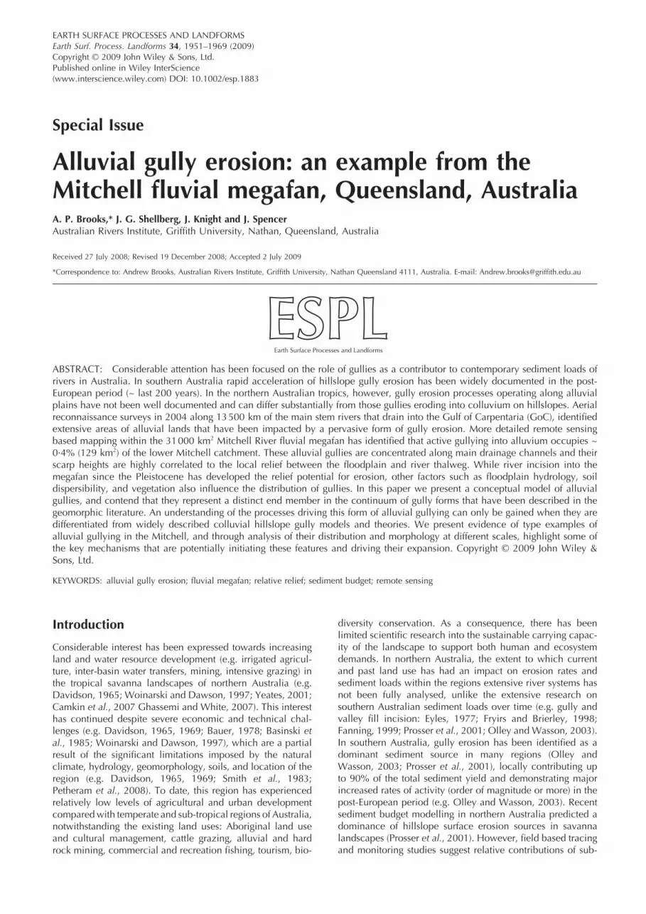
Alluvial gullies are here defi ned as relatively young inci-sional features entrenched into alluvium not previously incised since initial deposition. Alluvial gully complexes (up to several km2) are defi ned as actively eroding and expanding channel networks incised into and draining alluvial deposits. They often form a dense network of rills and small gullies nested hierarchically within larger macro-gully complexes (e.g. Figure 1). Alluvial gullies are variable in erosion process, form, landscape location, climate, relief, and texture of alluvium. However, they most often occur in vast deposits of alluvium along high stream-order main river channels or other large waterbodies such as lagoons or lakes (e.g. Figure 1). Thus they have high sediment delivery ratios and are highly connected sources of predominantly fi ne suspended sediment. They are often as wide or wider than they are long, due to the lack of structural control on their lateral expansion (Figure 1).
By defi nition, alluvial gullies erode drainage networks into some form of alluvium, which is a time varying storage com-
ALLUVIAL GULLY EROSION 1953
Copyright © 2009 John Wiley & Sons, Ltd. Earth Surf. Process. Landforms, Vol. 34, 1951–1969 (2009)DOI: 10.1002/esp
Figure 1. Histogram of gully pixel frequency from ASTER delineation in relation to pixel elevation determined from the 30 m SRTM DEM.

1954 A. P. BROOKS ET AL.
Copyright © 2009 John Wiley & Sons, Ltd. Earth Surf. Process. Landforms, Vol. 34, 1951–1969 (2009)DOI: 10.1002/esp
ponent of transported fl uvial sediment. Therefore, alluvial gully erosion represents a secondary cycle of erosion, occur-ring sometime after initial storage but before physical or chem-ical conversion into sedimentary rock. Primary and secondary erosion cycles that differentiate production, transport, and sink zones have been discussed by Schumm and Hadley (1957) and Pickup (1985, 1991). Following initial deposition, sink zones can become sediment production zones during a sec-ondary cycle following changes in intrinsic or extrinsic thresh-olds, such as the alteration of resisting forces due to vegetation reduction or changes in erosive forces due to base level change, or increased discharge.
Alluvial gully complexes differ from badlands, which are most often formed in soft rock terrain, such as marl or shale sedimentary rock (Gallart et al., 2002; Harvey, 2004) often which has experienced some form of uplift or re-exposure due to base level change (Bryan and Yair, 1982). It is acknowl-edged, however, that the term badland is poorly defi ned and some could view certain stages and scales of alluvial gully complexes as examples of badland erosion. We contend that describing alluvial gully complexes as ‘badland erosion’ does not help to explain the processes driving this form of erosion, and only serves to further cloud the literature on badland erosion. The features we describe clearly have much in common with the extensive literature on gullies and are best placed in the context of this literature.
Alluvial gullies also differ from the cut and fi ll incised land-scapes that occur along pre-existing linear channels in par-tially confi ned valleys fi lled with a mixture of alluvium,
colluvium, weathered rock and soil (e.g. Eyles, 1977; Prosser et al., 1994; Prosser and Winchester, 1996; Fryirs and Brierley, 1998), including arroyo (stream) channels (e.g. Schumm and Hadley, 1957; Cooke and Reeves, 1976; Graf, 1979). Fluvial processes along major stream channels that are structurally controlled by surrounding hillslopes and underlying bedrock differ signifi cantly to the processes operating in smaller allu-vial gully channels uninfl uenced by these structural controls. While hillslope gullies and cut and fi ll channels in headwater areas can erode into linear patches of alluvium, they are closer to the hillslope end of the continuum between pure colluvial and pure alluvial deposits and processes.
In the following section we outline the landscape context of the study area where we have described a type example of alluvial gullies and have mapped the extent of active gullies in a large savanna catchment.
Landscape Setting
Monsoonal climate and hydrology
The study area is located in the Mitchell River catchment (71 630 km2) in tropical northern Queensland, Australia and is concentrated in the lower half of the catchment where vast alluvial savanna plains (i.e. fl uvial megafan deposits of allu-vium, see later) cover 31 000 km2 (Figures 2a and 3). The Mitchell River catchment has one of the highest mean annual discharge volumes in Australia (>8 000 000 ML/y, excluding
Figure 2. Longitudinal profi le of the Mitchell River thalweg and adjacent megafan surface (fl oodplain or terrace). Locations of the key tributary confl uences are noted as distances upstream (km) as are current and past fl uvial megafan apexes.
ALLUVIAL GULLY EROSION 1955
Copyright © 2009 John Wiley & Sons, Ltd. Earth Surf. Process. Landforms, Vol. 34, 1951–1969 (2009)DOI: 10.1002/esp
the Alice River: QDNRW, 2008), despite being only the 13th largest by area. The tropical climate and resultant hydrology of the catchment is monsoonal and strongly seasonal (Hayden, 1988; Stewart, 1993; Petheram et al., 2008), with >80% of the mean annual rainfall (catchment mean 1015 mm; range 661 to 3396 mm) falling between the wet season months of December to March.
Geology
The upper half of the Mitchell catchment is dominated by rugged hillslope terrain with a maximum elevation of 1236 m and catchment mean of 245 m. The geology of the upper catchment is a heterogeneous mixture of metamorphic, igneous and sedimentary rock (Whitaker et al., 2006). The major structural control in the Mitchell catchment is the south-north striking, steeply dipping Palmerville fault (Vos et al., 2006), which is considered a reactivated Precambrian struc-ture (see Vos et al., 2006, for review). This fault separates the adjacent Palaeozoic Hodgkinson Province to the east from Proterozoic metamorphic rocks to the west, which are over-lain by fl uvial megafan deposits (Figure 3).
The study area and lower half of the catchment below 200 m elevation are located on the largest fl uvial megafan in Australia (sensu Horton and DeCelles, 2001; Leier et al., 2005), with an alluvial extent of 31 000 km2. The Mitchell fl uvial megafan was originally described in detail by Grimes and Doutch (1978), who defi ned and delineated distinct fan
units from the Pliocene to Holocene (Figure 2a). Over this period, sea level and climate change have resulted in at least fi ve cycles of fan building, with nested fan-in-fan forms devel-oped as megafan units coalesced and prograded toward the current estuarine delta in the Gulf of Carpentaria.
Megafan morphology
The morphological apex of the entire megafan is located near the confl uence of the Lynd and Mitchell Rivers (Figures 2a and 3), with narrower alluvial deposits backed up into the more confi ned river valleys upstream. Currently, the hydrologic apex of the Mitchell megafan is located below the confl uence of the Palmer and Mitchell Rivers. The current Mitchell River delta and its interconnected distributary deltas (including the North, Middle, and South Mitchell Arms; Topsy Creek; Nassau River) are in combination the largest river delta in Australia in terms of total mangrove area (>112 km2) and second largest in terms of total main channel length (>61 km) and perimeter (>300 km) (Heap et al., 2001).
Mitchell megafan units are dominated by alluvial silts and clays. Sand and some gravel are confi ned to the largest macro-channels (sensu van Niekerk et al., 1999) of the Mitchell and its main tributaries, which can span up to 2 km in width. The Mitchell River and it tributaries upstream of the Palmer River are incised into the megafan deposits due to megafan progra-dation into the Gulf of Carpentaria and possibly a reduction
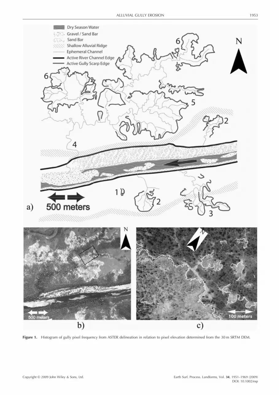
Figure 3. Relationship between measured gully head scarp height (SH) and adjacent fl oodplain surface elevation (El) as derived from the 30 m SRTM DEM.
1956 A. P. BROOKS ET AL.
Copyright © 2009 John Wiley & Sons, Ltd. Earth Surf. Process. Landforms, Vol. 34, 1951–1969 (2009)DOI: 10.1002/esp
in catchment sediment supply over the Holocene (Nanson et al., 1992; Tooth and Nanson, 1995).
Mitchell River channel morphology is dominated in the wet season by a relatively-straight, single-thread, macro-channel, which during the dry season contracts to a more sinuous low-fl ow channel with multiple secondary channels separated in places by vegetated islands. The location of the low-fl ow channel (thalweg) is highly dynamic, resulting in a shifting habitat mosaic (sensu Stanford et al., 2005) of in-channel riparian vegetation communities. The connectivity of fl ood-plains and channels across the megafan is highly dependent on river stage and discharge, when during fl ood stage (range 5 to 20 m above thalweg), water spreads across the megafan perirheic zone (sensu Mertes, 1997) (Figure 2b). Interconnected networks of fl oodways, anabranches and distributaries result in the complex mixing of perirheic (surface) water from differ-ent sources (river water, emergent groundwater, infi ltration-excess ponded surface water).
Soils
Across the megafan, soils have developed where alluvial sands, silts and clays have been relatively undisturbed physi-cally, but not chemically, since initial deposition. These soils have been described by the BRS (1991), and vary depending on age, elevation, and river connectivity. Near main river channels, ‘slightly elevated old fi lled channels and associated levees have sandy and loamy red earths, and occasionally lesser yellow earths’ (unit code Si14). Across most of the vast ‘alluvial plains fringing major rivers, often traversed by old infi lled stream channels and associated low levees, silty or loamy surfaced grey-brown duplex soils are dominant and are strongly alkaline at shallow depths. The A horizon depth ranges from 8 to 15 cm, and many areas have a scalded surface’ (Si14), due to the removal of the A horizon. Further away from the main river, ‘small swampy depressions and lower plains have grey cracking clays’ (Si14) (BRS, 1991).
The alluvial soils along the Mitchell River also appear to have a characteristic geochemistry, that to date has been poorly defi ned. Following the exposure of massive alluvial soils after gully erosion, nodules or pisoliths of ferricrete and calcrete readily form on the surface of exposed gullies (e.g. Pain and Ollier, 1992). Gully fl oors appear to be preferential zones of accumulation of cations (e.g. iron, manganese, and calcium) through local pedogenic processes (relative accumu-lation; e.g. McFarlane, 1991) and lateral groundwater input (absolute accumulation; e.g. McFarlane, 1976) or both (Goudie, 1973, 1984).
Catchment land use
Within the study area along the lower catchment megafan, land use is currently dominated by cattle grazing across savanna woodlands and unimproved grasslands (e.g. Neldner et al., 1997). These savanna vegetation communities are dynamic over space and time and strongly controlled by dis-turbance regimes (fi re, fl ood, grazing, erosion), which have changed following European settlement (Crowley and Garnett, 1998, 2000). The upper catchment is also dominated by hill-slope grazing on unimproved pastures, with developed agri-culture covering 2·6% of total catchment area in a relatively confi ned basaltic plain in the upper catchment. Locally sig-nifi cant areas of alluvial and hard rock mining occur through-out the catchment (McDonald and Dawson, 2004), with hard rock mining expanding in recent years.
Methods
Alluvial gully distribution across the Mitchell megafan
Mapping of alluvial gully erosion in the Mitchell River catch-ment was undertaken using Advanced Spaceborne Thermal Emission and Refl ection Radiometer (ASTER) scenes subset to extents covering the catchment. The remote sensing methods used to delineate active gully erosion area were described in detail in Brooks et al. (2008). In summary, a total of 10 ASTER scenes acquired across a fi ve year period from 2000, and across both the wet and dry season, were processed individu-ally using a standard remote sensing decision tree methodol-ogy to detect gully areas. To calibrate the method, the extent of gullies in subset areas was delineated with both LiDAR (light detection and ranging) generated DEMs (digital elevation models) and aerial photography, with parameter adjustment for individual ASTER scene differences. Validation involved using high resolution Quickbird imagery publicly available through Google Earth. Detection accuracy was estimated by comparing gully detection in 250 1 km cells randomly assigned and coincident with Quickbird coverage with the detection of gullies from the ASTER processing. Accuracy of gully delineation involved comparison of the aerial extent of gullies mapped from ASTER against manually digitized gully extent (bare, active gully areas) identifi ed in 83 1 km grid cells with active gullies, randomly selected from the 250 cells used in the detection validation process. For the current purposes, the delineation of individual gullies as mapped from ASTER imagery included the bare, actively eroding sections within the gully. Thus, where the inset lower surface of a gully was (re)vegetated, it was not mapped as a gully area.
For alluvial gully analysis, the megafan limits were delin-eated from a surface geology data set that describes the extent of fl oodplain and channel alluvium at 1 : 1 000 000 (Whitaker et al., 2006), as well as the 1 : 2M soil landscapes data set (BRS, 1991). Also, marine infl uenced areas and salt plains in the delta were delineated and excluded from the extent of the megafan, as they are controlled by a different set of process.
Gully position in relation to megafan geology and soils
Mapped gully areas were additionally compared to mapped megafan geologic units (Grimes and Doutch, 1978) and soil units (BRS, 1991). The frequency of mapped gully pixels (i.e. 15 m2 pixels from the ASTER based mapping) in these units were analysed to gain insight into the units that were most sensitive to gully erosion.
Gully pixel proximity to main channels
The proximity of mapped alluvial gully areas to main channels across the Mitchell megafan was estimated by measuring the linear distance between the centroid of each gully pixel mapped with ASTER and the nearest linear drainage line mapped at the 1 : 2 500 000 scale. At this scale, only the major creeks and rivers are displayed (Figure 3). This metric does not provide a measure of thalweg channel distance to main channel. In addition in rare occasions, the direction of the distances measured might be different than the actual fl ow direction, which could be longer or shorter. However given the large data set (>500 000 gully pixels), it was determined that this error was infrequent and minimal.

ALLUVIAL GULLY EROSION 1957
Copyright © 2009 John Wiley & Sons, Ltd. Earth Surf. Process. Landforms, Vol. 34, 1951–1969 (2009)DOI: 10.1002/esp
Only pixels from within the bare, actively eroding areas of gullies were used for distance measures. Because the analysis was conducted at a pixel level, larger gullies, compared with smaller gullies, dominate in this type of approach. However at the catchment scale, this metric provides a method to assess overall gully proximity to channels.
Elevation at gully pixels
For each pixel of each mapped gully, elevation was extracted from a 30 m DEM rectifi ed to Australian Height Datum (AHD) (SRTM DTED2, 2000). As vegetated sections of gullies were not delineated by the mapping, the pixels mapped as bare, actively eroding areas tend to be concentrated toward the higher eleva-tions of a given gully complex, and thus are biased towards these higher elevations (potentially in the order of 1–2 m). Nevertheless, this bias should not unduly mask the pattern at the megafan scale, in which the elevation range is 180 m.
Gully position in relation to megafan relief
Relative relief was defi ned as the relative difference in eleva-tion between the main channel thalweg and the relatively-fl at, high-fl oodplain surface along the megafan. Relative relief was hypothesized to be a key control on gully activity and gully scarp height. Using the 1 : 250 000 drainage network and the 30 m SRTM DEM, channel to fl oodplain cross-sections were extracted at 20 km intervals down the longitudinal profi le of the Mitchell River. From each cross-section, elevations of the thalweg (low point) and fl oodplain (i.e. the most frequent elevational highpoint) were determined as a pair and the rela-tive difference (relief) between the two was calculated. In total, this provided a longitudinal profi le of relative relief down the megafan.
Longitudinal gully profi les and scarp heights
Near vertical scarp heights at gully fronts were estimated using both fi eld and remotely sensed data. Airborne LiDAR surveys of gullies were conducted in 2006 at four sites across the megafan. Within each LiDAR site, three longitudinal profi les of gully channels were measured, to calculate the height of the near vertical scarp and assess slopes above and below
scarps. To supplement these data, measurements of scarp height were collected at fi eld sites (Figure 3). In combination, these data were used to develop a distribution of gully scarp heights and form a basis for understanding patterns of gully distribution across the Mitchell megafan.
Erosion rates at gully fronts
Detailed surveys of selected alluvial gully fronts (scarps) in the Mitchell megafan were conducted using in situ differential global positioning system (GPS) with sub-meter accuracy (Trimble with Omnistar High Precision). Accuracy depended on signal strength and vegetation cover, but was typically within 0·5 m for repeat surveys. GPS surveys were conducted at nine sites across the alluvial megafan, totalling 25 485 m of gully front, surveyed repeatedly as shown in Table I and Figure 3. Gully expansion indicated by average scarp retreat rate was determined from annual surveys in 2005, 2006, and 2007, with the average rate equalling the total erosion area of change during any given year divided by the total common survey length, for each gully surveyed. Maximum linear rates were calculated for individual lobes, but only the average rate was applied across the entire length for budget purposes (see Brooks et al. 2008) (Table I).
In Brooks et al. (2008), it was assumed the majority of new sediment contributed to the gully each year comes from primary vertical scarp retreat at the gully head. This is not to say that appreciable volumes of sediment are not coming from secondary erosion of incompletely eroded failed blocks, reworking of gully outwash deposits, or gully sidewall erosion. Indeed scarp retreat will slow if the deposited material is not reworked from the gully fl oor. Recent observations suggest, however, that due to the highly dispersible nature of the sedi-ments and the fact that most of the sediment is going into suspension, material delivered from the head scarp is removed reasonably effi ciently (Figure 12). The same observations, coupled with survey data, indicate that due to the high rates of head scarp retreat (Table I, Figure 9) the majority of volu-metric change in the gully void on an annual timescale is directly proportional to the head scarp retreat rate. Hence, head scarp retreat rate can provide an easily measurable indi-cator of minimum annual sediment supply from alluvial gul-lying when combined with gully scarp height data at individual gullies (Brooks et al. 2008).
Table I. Surveyed lengths and erosion rates at alluvial gully head scarps sites
Years Site ID Survey length (m) Maximum retreat (m/y) Mean retreat (m/y)
2006–2007 MMGC1 832 8·13 0·102005–2006 MMGC1 773 6·50 0·322006–2007 WPGC1 554 2·03 0·032006–2007 WPGC2 6782 10·26 0·382006–2007 WPGC3 4140 6·60 0·302005–2006 WPGC3 2534 8·09 0·092006–2007 GBGC1 1525 1·32 –2005–2006 GBGC1 1431 1·93 –2006–2007 GBGC2 969 14·10 0·822006–2007 GBGC3 1843 4·51 0·652006–2007 HBGC1 1763 3·85 0·532006–2007 KWGC1 2339 3·20 0·36
Total 25485Median (50) 5·51 0·3425th Percentile 2·91 0·1575th Percentile 8·10 0·49
1958 A. P. BROOKS ET AL.
Copyright © 2009 John Wiley & Sons, Ltd. Earth Surf. Process. Landforms, Vol. 34, 1951–1969 (2009)DOI: 10.1002/esp
Hydrologic monitoring
Initial insights into the key hydrologic drivers of gully erosion are being elucidated by measuring continuous water stage at several locations within different gully complexes. Local rain-fall is also measured with automated tipping bucket rain-gauges. The positioning of stage recorders within the gully fl oor as well as at the gully outlet channel allows us to distin-guish between locally derived storm events and main stem river channel backwater and/or overbank events. The gauge network is also complemented with automatic time lapse cameras that capture daily images of gully head scarp retreat throughout the wet season (November–April). Analysis of the time lapse camera images coupled with the stage and rainfall records allows us to link the main hydrologic processes (rain-splash, surface runoff, groundwater sapping, gully backwater or overbank fl ooding) with the main periods of erosive activ-ity. It is worth noting that the fi eld area is completely inacces-sible through the wet season, requiring all monitoring to be automated.
Results
Alluvial gully distribution across the Mitchell megafan
The detection accuracy of gullies varied between ASTER scenes because of acquisition time differences (both interan-nual and season) and variations in size and spectral responses of individual alluvial gullies. Based on the validation of gully detection from 250 randomly selected 1 km cells, the ASTER image detected 45 (18%) false positives and 18 (7%) false negatives. These results indicate that signifi cant classifi cation errors can occur when using remote sensing to detect alluvial gullies. False negatives were a result of lack of resolution in the ASTER and ability to detect small linear gullies in heavily vegetated areas. False positives represented the detection of either (1) bare surfaces stripped of their shallow A-horizon and grass vegetation, (2) the bed of small, dry seasonal wetlands, or (3) road surfaces. Overall however, the ASTER classifi cation was successful in detecting the largest alluvial gully com-plexes between 1 ha and 1 km2.
After the initial validation exercise, roads (false positives) across the entire megafan were manually removed from the dataset, representing a 28 km2 reduction in ASTER detection area. The remaining error was corrected for via the Quickbird validation procedure, where gully area, gully perimeter, and scarp length adjustments were applied from the data derived from the 83 randomly selected 1 km cells manually digitized at high resolution (see Brooks et al., 2008, for more detail).
Mapped gully pixels and polygons were then amalgamated into 1 km2 gully density grids for fi nal distribution map dis-played in Figure 3. In total, the analysis identifi ed 129 km2 of active alluvial gullies within the Mitchell megafan (31 000 km2), which represents 0·4% of the land area. This should be treated as an absolute minimum area of alluvial gullies, as gullies masked by vegetation were not detected and delineated. The estimated active front length of alluvial gullies was 5567 km.
Gully position in relation to megafan geology and soils
Mapped gully pixels were most frequently located (56%) on megafan units described as Pleistocene by Grimes and Doutch (1978) (Figure 2a). Adjacent units mapped as Pliocene in age
contained 41% of the mapped gully area, while Holocene units only contained 3% of the mapped gullies. These results indicate that older alluvium deposits in higher elevation areas of the megafan are most prone to erosion, while active Holocene aggradational areas are less prone to erosion. However, caution should be used when interpreting these results, due to the coarse nature of the original mapping exer-cise (Grimes and Doutch, 1978; Figure 2a), and the lack of absolute dates for alluvium across the lower Mitchell catchment.
In relation to published alluvial soil descriptions (BRS, 1991) across the Mitchell megafan, 50% of mapped gully pixel area had soils described as ‘alluvial plains . . . with silty or loamy surfaced grey-brown duplex soils [that] are strongly alkaline at shallow depths’ (unit code Si14). A further 21% of the mapped gully pixel area was associated with ‘gently undu-lating plains with . . . sandy to loamy yellow earths . . . grey duplex soils . . . and ironstone nodules at depth’ (unit code Mr11). While 13% of the mapped gully pixel area was associ-ated with ‘slightly elevated old stream terraces, levees, and infi lled channels associated with sandy or loamy red earths and yellow earths . . . that are usually stratifi ed at depth’ (unit code Mw40).
Gully pixel proximity to main channels
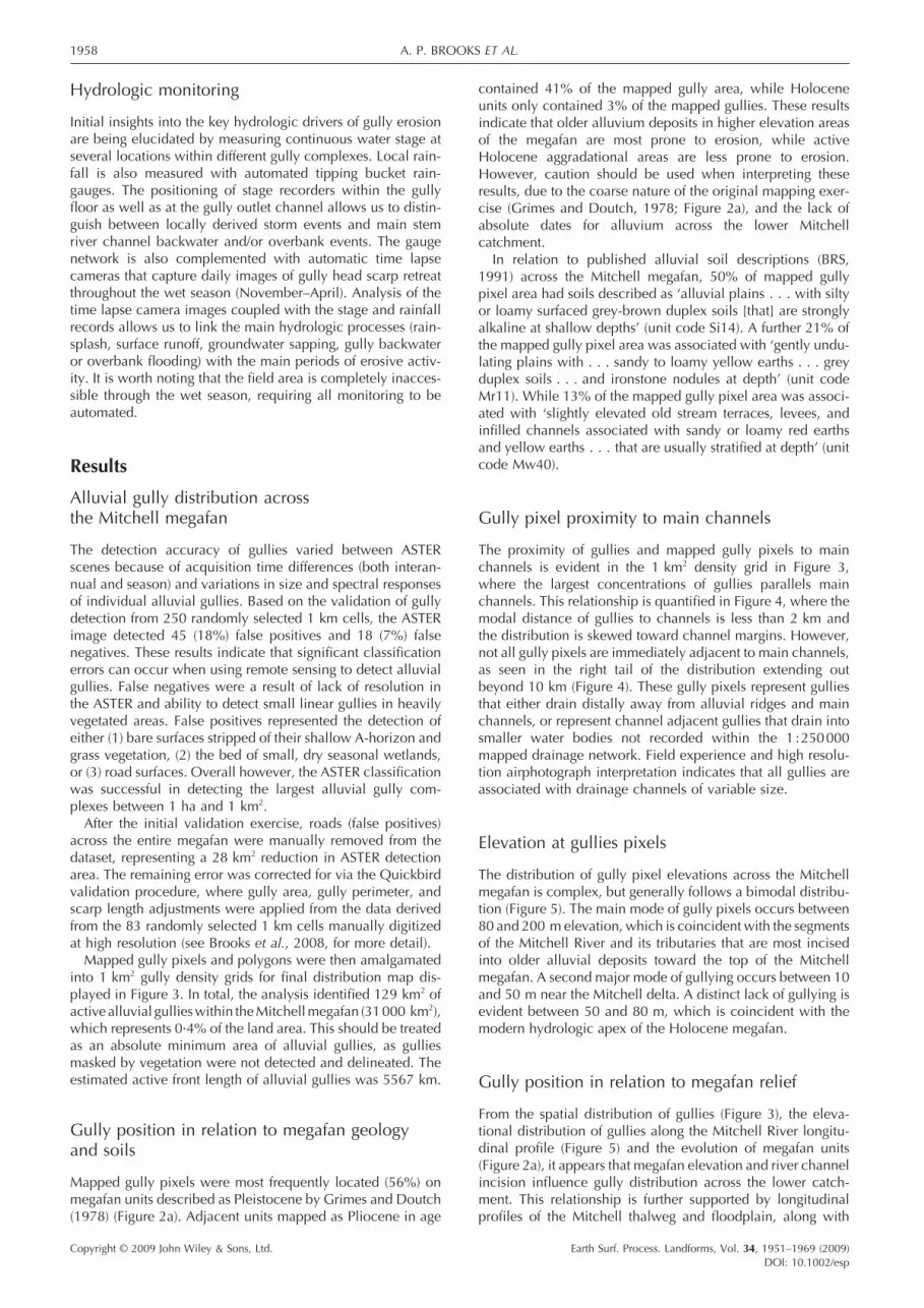
The proximity of gullies and mapped gully pixels to main channels is evident in the 1 km2 density grid in Figure 3, where the largest concentrations of gullies parallels main channels. This relationship is quantifi ed in Figure 4, where the modal distance of gullies to channels is less than 2 km and the distribution is skewed toward channel margins. However, not all gully pixels are immediately adjacent to main channels, as seen in the right tail of the distribution extending out beyond 10 km (Figure 4). These gully pixels represent gullies that either drain distally away from alluvial ridges and main channels, or represent channel adjacent gullies that drain into smaller water bodies not recorded within the 1 : 250 000 mapped drainage network. Field experience and high resolu-tion airphotograph interpretation indicates that all gullies are associated with drainage channels of variable size.
Elevation at gullies pixels
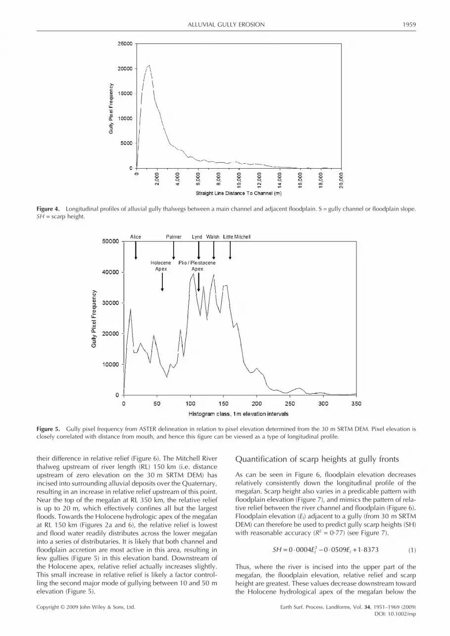
The distribution of gully pixel elevations across the Mitchell megafan is complex, but generally follows a bimodal distribu-tion (Figure 5). The main mode of gully pixels occurs between 80 and 200 m elevation, which is coincident with the segments of the Mitchell River and its tributaries that are most incised into older alluvial deposits toward the top of the Mitchell megafan. A second major mode of gullying occurs between 10 and 50 m near the Mitchell delta. A distinct lack of gullying is evident between 50 and 80 m, which is coincident with the modern hydrologic apex of the Holocene megafan.
Gully position in relation to megafan relief
From the spatial distribution of gullies (Figure 3), the eleva-tional distribution of gullies along the Mitchell River longitu-dinal profi le (Figure 5) and the evolution of megafan units (Figure 2a), it appears that megafan elevation and river channel incision infl uence gully distribution across the lower catch-ment. This relationship is further supported by longitudinal profi les of the Mitchell thalweg and fl oodplain, along with
ALLUVIAL GULLY EROSION 1959
Copyright © 2009 John Wiley & Sons, Ltd. Earth Surf. Process. Landforms, Vol. 34, 1951–1969 (2009)DOI: 10.1002/esp
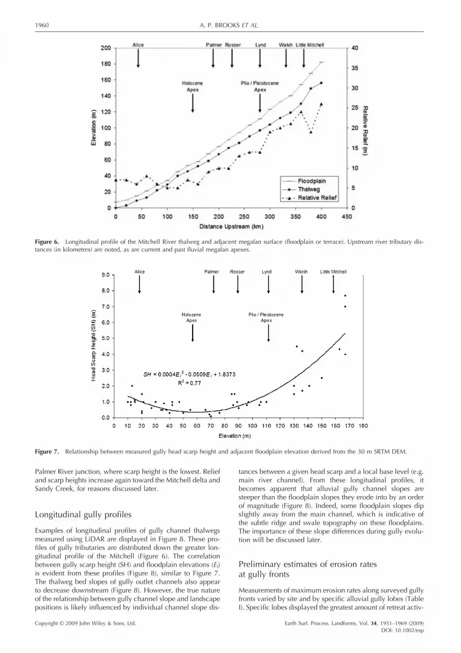
their difference in relative relief (Figure 6). The Mitchell River thalweg upstream of river length (RL) 150 km (i.e. distance upstream of zero elevation on the 30 m SRTM DEM) has incised into surrounding alluvial deposits over the Quaternary, resulting in an increase in relative relief upstream of this point. Near the top of the megafan at RL 350 km, the relative relief is up to 20 m, which effectively confi nes all but the largest fl oods. Towards the Holocene hydrologic apex of the megafan at RL 150 km (Figures 2a and 6), the relative relief is lowest and fl ood water readily distributes across the lower megafan into a series of distributaries. It is likely that both channel and fl oodplain accretion are most active in this area, resulting in few gullies (Figure 5) in this elevation band. Downstream of the Holocene apex, relative relief actually increases slightly. This small increase in relative relief is likely a factor control-ling the second major mode of gullying between 10 and 50 m elevation (Figure 5).
Quantifi cation of scarp heights at gully fronts
As can be seen in Figure 6, fl oodplain elevation decreases relatively consistently down the longitudinal profi le of the megafan. Scarp height also varies in a predicable pattern with fl oodplain elevation (Figure 7), and mimics the pattern of rela-tive relief between the river channel and fl oodplain (Figure 6). Floodplain elevation (El) adjacent to a gully (from 30 m SRTM DEM) can therefore be used to predict gully scarp heights (SH) with reasonable accuracy (R2 = 0·77) (see Figure 7).
SH E El l= ⋅ − ⋅ + ⋅0 0004 0 0509 1 83732 (1)
Thus, where the river is incised into the upper part of the megafan, the fl oodplain elevation, relative relief and scarp height are greatest. These values decrease downstream toward the Holocene hydrological apex of the megafan below the
Figure 4. Longitudinal profi les of alluvial gully thalwegs between a main channel and adjacent fl oodplain. S = gully channel or fl oodplain slope. SH = scarp height.
Figure 5. Gully pixel frequency from ASTER delineation in relation to pixel elevation determined from the 30 m SRTM DEM. Pixel elevation is closely correlated with distance from mouth, and hence this fi gure can be viewed as a type of longitudinal profi le.
1960 A. P. BROOKS ET AL.
Copyright © 2009 John Wiley & Sons, Ltd. Earth Surf. Process. Landforms, Vol. 34, 1951–1969 (2009)DOI: 10.1002/esp
Palmer River junction, where scarp height is the lowest. Relief and scarp heights increase again toward the Mitchell delta and Sandy Creek, for reasons discussed later.
Longitudinal gully profi les
Examples of longitudinal profi les of gully channel thalwegs measured using LiDAR are displayed in Figure 8. These pro-fi les of gully tributaries are distributed down the greater lon-gitudinal profi le of the Mitchell (Figure 6). The correlation between gully scarp height (SH) and fl oodplain elevations (El) is evident from these profi les (Figure 8), similar to Figure 7. The thalweg bed slopes of gully outlet channels also appear to decrease downstream (Figure 8). However, the true nature of the relationship between gully channel slope and landscape positions is likely infl uenced by individual channel slope dis-
tances between a given head scarp and a local base level (e.g. main river channel). From these longitudinal profi les, it becomes apparent that alluvial gully channel slopes are steeper than the fl oodplain slopes they erode into by an order of magnitude (Figure 8). Indeed, some fl oodplain slopes dip slightly away from the main channel, which is indicative of the subtle ridge and swale topography on these fl oodplains. The importance of these slope differences during gully evolu-tion will be discussed later.
Preliminary estimates of erosion rates at gully fronts
Measurements of maximum erosion rates along surveyed gully fronts varied by site and by specifi c alluvial gully lobes (Table I). Specifi c lobes displayed the greatest amount of retreat activ-
Figure 6. Longitudinal profi le of the Mitchell River thalweg and adjacent megafan surface (fl oodplain or terrace). Upstream river tributary dis-tances (in kilometres) are noted, as are current and past fl uvial megafan apexes.
Figure 7. Relationship between measured gully head scarp height and adjacent fl oodplain elevation derived from the 30 m SRTM DEM.

ALLUVIAL GULLY EROSION 1961
Copyright © 2009 John Wiley & Sons, Ltd. Earth Surf. Process. Landforms, Vol. 34, 1951–1969 (2009)DOI: 10.1002/esp
ity, while a majority of the scarp length experiences less activ-ity (Figure 9). For example, only 17% of the scarp length surveyed showed measurable signs of retreat, while some lobes eroded up to 14 m/y in certain locations.
Using an average rate of scarp retreat of 0·34 m/y (Table I), distributed scarp heights ranging between 0·3 and 8 m, and an active alluvial gully front length of 5567 km, Brooks et al. (2008) estimated that >5 Mt/y of fi ne alluvial sediment was eroded from alluvial gullies per year across the Mitchell fl uvial megafan.
Discussion
Controls on distribution
From this analysis of alluvial gully distribution across the lower Mitchell catchment and megafan, several primary factors controlling the potential development of alluvial gullies emerge. A prerequisite for the occurrence of alluvial gulling is the initial deposition of alluvium, which in this case, has largely been controlled by the development of the Mitchell
Figure 8. Longitudinal profi les of alluvial gully thalwegs between a main channel and adjacent fl oodplain. S = gully channel or fl oodplain slope. SH = scarp height.
Figure 9. Annual gully scarp position between 2005 and 2007 at WPGC3. Note: cross over of some lines in inactive gully sections is due to measurement error, which is a combined function of limitations in the resolution of the Omnistar HP differential GPS survey technique, and the retracing of the survey track in consecutive years.

1962 A. P. BROOKS ET AL.
Copyright © 2009 John Wiley & Sons, Ltd. Earth Surf. Process. Landforms, Vol. 34, 1951–1969 (2009)DOI: 10.1002/esp
megafan from the Pliocene to Holocene. While the Mitchell River traverses what initially appears to be a vast expanse of homogenous alluvium, the actual heterogeneity in depth, width, texture, and chemistry of the deposits strongly infl u-ences the potential for alluvial gully development. Silty or loamy duplex soils with alkalinity at depth are most prone to gully erosion, due to their texture, chemistry, and river prox-imity. Coarse sand deposits within and near the river macro-channel, and clay wetland deposits tens of kilometres away from the main- and palaeo-channels, appear less vulnerable to alluvial gully erosion.
The erosional potential of these soils is enhanced by the incision of the Mitchell River into the upper sections of the megafan, which has increased local relative relief, and set up the potential energy needed for a secondary cycle of erosion into the adjacent Pliocene and Pleistocene alluvium. The strong relationships between local relative relief and gully scarp height and gully density support the idea that relief is a primary factor infl uencing alluvial gully erosion. The concept of relative relief and erosion potential is also applicable in the Mitchell River delta below the current hydrologic fan apex. Here, alluvial sediments have accumulated both behind and beyond the main Pleistocene chenier ridge. Over the last 6000 years, these sediments have been slightly elevated relative to sea level, due to a decline in regional sea levels (Chappell, 1983; Woodroffe and Chappell, 1993; Woodroffe and Horton, 2005) and/or hydroisostatic warping (uplift) (Rhodes, 1982; Chappell et al., 1982). Thus, in both the upper and lower sec-tions of the Mitchell megafan, local base level (of the adjacent channel) infl uences potential energy available for gully erosion.
Classifi cation of alluvial gully forms
Numerous insights into the various alluvial gully types were made using ground observations, ground photographs, aerial photographs, LiDAR topography, ASTER images, and direct measurement. Classifi cation of gully types and understanding of basic gully processes were used to develop a conceptual model of alluvial gully evolution below. While many addi-tional alluvial gully types likely exist across the extremely diverse landscape around the GoC, our observations from several hundred alluvial gullies in the Mitchell catchment and other drainages to the GoC indicate that there are some com-monalities in form across the landscape.
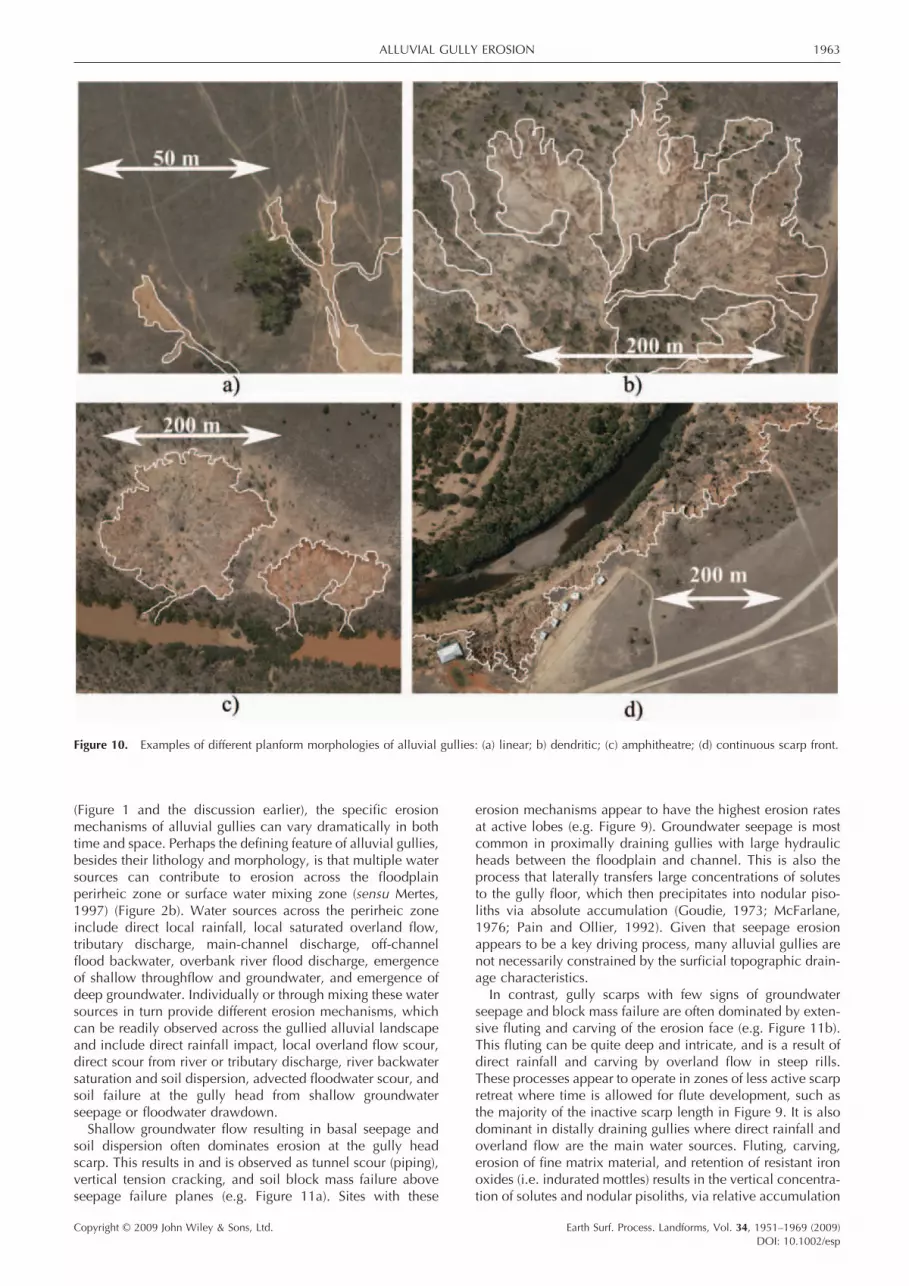
As a way of providing some insight into gully process and evolution, the planform morphology of alluvial gullies can be broadly classifi ed into four major groups (Brooks et al., 2006). Linear: these gullies have elongate planform morphologies without well developed secondary drainage networks. They are likely to be an incipient phase of other gully forms, which are usually preceded by rilling. They are also commonly asso-ciated with anthropogenic disturbances such as roads, stock tracks, or other linear disturbances that tend to concentrate overland fl ow (e.g. Figure 10a). In many respects, linear allu-vial gullies early in developmental stages are little different to the standard hillslope gully model (discussed later). Dendritic: these gullies are associated with well defi ned drainage net-works, separated by distinct interfl uves. The gully head is often indistinct, grading relatively gradually into the adjacent fl ood-plain (e.g. Figure 10b). Amphitheatre: these gullies are often as wide as or wider than they are long, due to the lack of structural control on their lateral expansion. They have well developed head scarps around three-quarters of the gully perimeter, and drain into relatively narrow outlet channels on the proximal or distal sides of alluvial ridges (e.g. Figure 10c).
Continuous Scarp Front: these steep scarped gullies are located parallel with the main stem channel of major rivers. They develop from the coalescence of numerous amphitheatre gullies and/or from river bank erosion on meander bends. Thus they are either more mature than other forms (e.g. Figure 10d), or indicate sites where there has been a higher density of initiated gullies and/or higher lateral expansion rates leading to the coalescence of the gullies into a scarp front.
Further insight into the hydrologic processes driving alluvial gullying can be gained through analysis of their location within the fl oodplain and their proximity to the primary or subsidiary channel networks. Based on location, six alluvial gully types are generally observed across the alluvial land-scape, which are highlighted and numbered in Figure 1 cor-responding with numbers and descriptions below.
(1) Incipient Alluvial Gullies: These small, generally linear gullies are fairly ubiquitous along the proximal banks and shallow alluvial ridges and levees of water bodies such as large rivers and their off-channel lagoons. They are often of recent development, growing out of rills developed along preferential surface fl ow paths and to a lesser extent groundwater seepage. Depending on available gradient and water sources, they may or may not develop further after initiation.
(2) Bounded Proximal Alluvial Gullies: These moderately developed gullies drain off shallow alluvial ridges toward the main water body. Where relatively resistant portions of alluvial ridges are encountered during gully basin devel-opment, the alluvial ridge acts as a drainage divide and ultimate controller of extent.
(3) Unbounded Proximal Alluvial Gullies: These moderately developed gullies also drain off shallow alluvial ridges toward the main water body. However, they have cut through relatively weaker points in shallow ridges, extend-ing their drainage networks into the distal parts of the fl oodplain. Concepts of surface and groundwater divides breakdown with these gully types. Scarp retreat is not driven by surface runoff in this type of gully.
(4) Unbounded Alluvial Gully Complexes: These relatively large catchments drain portions of distal fl oodplains. They have well developed gullied tributaries that each develops uniquely depending on their location and orientation. In sum, these gully complexes can form larger, fractal ver-sions of smaller alluvial gullies. Since they cut through alluvial ridges either before or after ridge formation, they are relatively unbounded and unconstrained in their development.
(5) Bounded Distal Gullies: These moderately developed gullies drain off relatively resistant portions of alluvial ridges away from the main channel, towards distal parts of the fl oodplain into tributaries, lagoons, backswamps, or larger gully complexes. Due to long channel slope dis-tances to the main channel, their scarp heights are usually smaller than their adjacent proximal gullies, given the more gradual gully fl oor slope.
(6) Unbounded Distal Gullies: These gullies are tributary to large gully complexes draining distal portions of the fl ood-plain. They are relatively unconstrained by alluvial ridges near channels, but could be constrained by available water sources.
Hydrologic mechanisms for erosion
Largely depending on the gully position in the alluvial land-scape and its connectivity with main channel hydrology
ALLUVIAL GULLY EROSION 1963
Copyright © 2009 John Wiley & Sons, Ltd. Earth Surf. Process. Landforms, Vol. 34, 1951–1969 (2009)DOI: 10.1002/esp
(Figure 1 and the discussion earlier), the specifi c erosion mechanisms of alluvial gullies can vary dramatically in both time and space. Perhaps the defi ning feature of alluvial gullies, besides their lithology and morphology, is that multiple water sources can contribute to erosion across the fl oodplain perirheic zone or surface water mixing zone (sensu Mertes, 1997) (Figure 2b). Water sources across the perirheic zone include direct local rainfall, local saturated overland fl ow, tributary discharge, main-channel discharge, off-channel fl ood backwater, overbank river fl ood discharge, emergence of shallow throughfl ow and groundwater, and emergence of deep groundwater. Individually or through mixing these water sources in turn provide different erosion mechanisms, which can be readily observed across the gullied alluvial landscape and include direct rainfall impact, local overland fl ow scour, direct scour from river or tributary discharge, river backwater saturation and soil dispersion, advected fl oodwater scour, and soil failure at the gully head from shallow groundwater seepage or fl oodwater drawdown.
Shallow groundwater fl ow resulting in basal seepage and soil dispersion often dominates erosion at the gully head scarp. This results in and is observed as tunnel scour (piping), vertical tension cracking, and soil block mass failure above seepage failure planes (e.g. Figure 11a). Sites with these
erosion mechanisms appear to have the highest erosion rates at active lobes (e.g. Figure 9). Groundwater seepage is most common in proximally draining gullies with large hydraulic heads between the fl oodplain and channel. This is also the process that laterally transfers large concentrations of solutes to the gully fl oor, which then precipitates into nodular piso-liths via absolute accumulation (Goudie, 1973; McFarlane, 1976; Pain and Ollier, 1992). Given that seepage erosion appears to be a key driving process, many alluvial gullies are not necessarily constrained by the surfi cial topographic drain-age characteristics.
In contrast, gully scarps with few signs of groundwater seepage and block mass failure are often dominated by exten-sive fl uting and carving of the erosion face (e.g. Figure 11b). This fl uting can be quite deep and intricate, and is a result of direct rainfall and carving by overland fl ow in steep rills. These processes appear to operate in zones of less active scarp retreat where time is allowed for fl ute development, such as the majority of the inactive scarp length in Figure 9. It is also dominant in distally draining gullies where direct rainfall and overland fl ow are the main water sources. Fluting, carving, erosion of fi ne matrix material, and retention of resistant iron oxides (i.e. indurated mottles) results in the vertical concentra-tion of solutes and nodular pisoliths, via relative accumulation
Figure 10. Examples of different planform morphologies of alluvial gullies: (a) linear; b) dendritic; (c) amphitheatre; (d) continuous scarp front.

1964 A. P. BROOKS ET AL.
Copyright © 2009 John Wiley & Sons, Ltd. Earth Surf. Process. Landforms, Vol. 34, 1951–1969 (2009)DOI: 10.1002/esp
Figure 11. Ground photographs of (a) mass failure, and (b) fl uting and carving at head scarps.
per decensum (Goudie, 1973; McFarlane 1991; Pain and Ollier, 1992).
Thus, varying alluvial gully erosion mechanisms in space and time at channel heads can span the full continuum of erosion models (Kirkby and Chorley, 1967): from the end member of groundwater outcrop erosion (De Vries, 1976) to shallow Darcian throughfl ow and return fl ow erosion (Kirkby and Chorley, 1967) to shallow non-Darcian macropore and pipe fl ow erosion (Kirkby, 1988; Bryan and Jones, 1997) to saturated overland fl ow (Dunne and Black, 1970) to pure Hortonian overland fl ow (Horton, 1933).
River backwater and overbank fl ooding of alluvial gullies can overwhelm these earlier mentioned erosion processes, by temporarily changing catchment divides and introducing a new suite of fl uvial processes. This is especially common in proximally draining gullies that are well connected to main river channels with peak stage heights ranging from 5 to 20 m. For example, Figure 12 displays a photographic sequence of alluvial gully erosion over one wet season, beginning with rainfall induced erosion and progressing to backwater induced erosion and soil dispersion, overbank fl ooding, overland runoff, and fi nally groundwater seepage induced erosion. While most alluvial gully erosion only entails one or a few of these processes, this example serves as a more complicated extreme where many hydrologic erosion processes can inter-act in time and space.
Unique profi le form of alluvial gullies
In contrast to hillslope gullies, mature alluvial gully channel slopes are often steeper than the lower gradient alluvial depos-its (e.g. fl oodplains) they erode into (Figure 8). The major change in relief between gully channels and the river fl ood-plains they cut into is typically located at the mouth of the gullies at the interface between the fl oodplain and river macro-channel or other water body. These mature alluvial gully channel profi les are similar to observations of channel profi le development through wedges of sediment following changes in base level, such as with dam removal (e.g. Galay, 1983; Cantelli et al., 2003).
In contrast to these mature alluvial gully profi les; hillslope gullies typically have channel slopes that are lower than the
hill slope (M. Kirkby, personal communication, and this issue). These differences suggest that there are fundamentally differ-ent erosion processes at work within hillslope gullies com-pared to alluvial gullies. Under hillslope erosional models, surface and shallow subsurface runoff from steeper hillslopes converge into gully heads where the slope breaks from steep to shallow. Stream power (i.e. slope and discharge) is typically high at these gully heads, surpassing thresholds for erosion initiation.
With mature alluvial gullies, surface water tends not to converge at the gully head, but subsurface water can converge at active erosional gully lobes. This subsurface water emerges at the gully head and break-in-slope at the base of the head scarp, and is combined with diffuse rainfall runoff and river fl ood- and back-water. Erosion is a partial result of convergent groundwater, but more importantly a result of the highly dis-persive nature of the subsurface alluvium. It is not until after numerous alluvial gully tributaries combine into a main gully channel that stream power likely reaches its maximum in a given alluvial gully. This maximum stream power is likely coincident with the zone of deepest incision into fl oodplain alluvium toward the mouth of the gully complex.
The exception to this rule of alluvial gully channels having steeper slopes than surrounding fl oodplains is during the incipient stages of alluvial gully erosion. On steep bank slopes along water bodies (i.e. channels and lagoons or cutoffs), alluvial gullies are initiated from overland fl ow rills, bank seepage, or other disturbance. During this initial stage of channel development, the channel slope is lower than the bank slope. However as the channel incises and progresses up the bank, the channel head can migrate beyond the top of the bank and continues eroding into surrounding fl oodplain alluvium. This is the point where the gully fl oor to alluvial surface slope ratio changes from less than one to greater than one. This is also the point that slightly negative fl oodplain slopes can be encountered, due to subtle alluvial ridge topog-raphy. As the gully continues to develop into fl oodplain allu-vium, the channel slope continues to remain stable or decline as an equilibrium profi le develops (Figure 8). However, the alluvial channel slope never returns to less than the fl oodplain or hill slope. That the gully can continue to expand into fl at alluvium suggests that surface derived fl ow is no longer driving headward retreat, and that direct subsoil dispersion is the dominant erosion process.
ALLUVIAL GULLY EROSION 1965
Copyright © 2009 John Wiley & Sons, Ltd. Earth Surf. Process. Landforms, Vol. 34, 1951–1969 (2009)DOI: 10.1002/esp
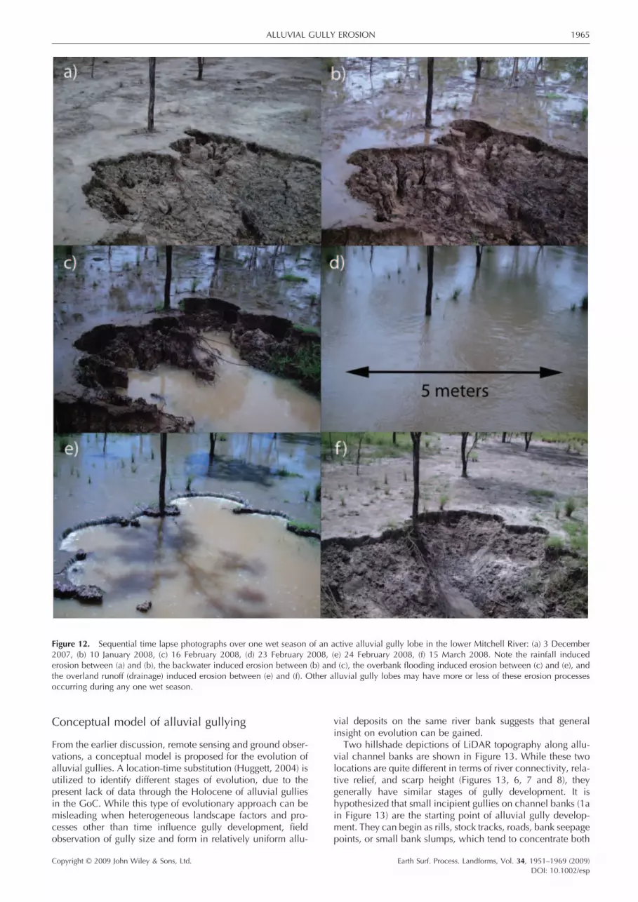
Figure 12. Sequential time lapse photographs over one wet season of an active alluvial gully lobe in the lower Mitchell River: (a) 3 December 2007, (b) 10 January 2008, (c) 16 February 2008, (d) 23 February 2008, (e) 24 February 2008, (f) 15 March 2008. Note the rainfall induced erosion between (a) and (b), the backwater induced erosion between (b) and (c), the overbank fl ooding induced erosion between (c) and (e), and the overland runoff (drainage) induced erosion between (e) and (f). Other alluvial gully lobes may have more or less of these erosion processes occurring during any one wet season.
Conceptual model of alluvial gullying
From the earlier discussion, remote sensing and ground obser-vations, a conceptual model is proposed for the evolution of alluvial gullies. A location-time substitution (Huggett, 2004) is utilized to identify different stages of evolution, due to the present lack of data through the Holocene of alluvial gullies in the GoC. While this type of evolutionary approach can be misleading when heterogeneous landscape factors and pro-cesses other than time infl uence gully development, fi eld observation of gully size and form in relatively uniform allu-
vial deposits on the same river bank suggests that general insight on evolution can be gained.
Two hillshade depictions of LiDAR topography along allu-vial channel banks are shown in Figure 13. While these two locations are quite different in terms of river connectivity, rela-tive relief, and scarp height (Figures 13, 6, 7 and 8), they generally have similar stages of gully development. It is hypothesized that small incipient gullies on channel banks (1a in Figure 13) are the starting point of alluvial gully develop-ment. They can begin as rills, stock tracks, roads, bank seepage points, or small bank slumps, which tend to concentrate both

1966 A. P. BROOKS ET AL.
Copyright © 2009 John Wiley & Sons, Ltd. Earth Surf. Process. Landforms, Vol. 34, 1951–1969 (2009)DOI: 10.1002/esp
Figure 13. LiDAR DEM hillshades of alluvial gullies at different stages of evolution. (a) The Mitchell River at an upstream distance of 370 km (Figure 6) and fl oodplain elevation of 160 m (Figure 7). Note the longitudinal profi le (MMGC3) in Figure 8 from the same area (black line). (b) A lagoon and palaeo-channel of the Mitchell River at an upstream distance of 210 km (Figure 6) and fl oodplain elevation of 85 m (Figure 7). Note the longitudinal profi le (HBGC777) in Figure 8 from the same area (black line). Numbered gully labels in fi gures refer to stages of gully evolution: 1a to 1c are incipient gully stages, 2a and 2b are, respectively, bounded and unbounded proximal gully stages.
surface and subsurface fl ow (Dunne, 1980, 1990). From their initially shallow channels and ubiquitous presence along steep alluvial banks, it is hypothesized that preferential groundwater fl ow paths are not requisite for channel initiation. Rather, concentrated overland fl ow following rainfall or fl ood-ing over steep banks is the dominant initial erosion mecha-nism, which is enhanced or resisted by surface soil condition and vegetative cover.
Over time, these incipient gullies (Figure 13, 1a) can develop further as they incise into alluvial banks and cut back into adjacent fl at fl oodplains (Figure 13, 1b and 1c). Their further growth and development highly depends on available surface and subsurface water sources needed for erosion. The depth of gully development and the extent of lateral expansion also depend on the relative depth of dispersive sub-soil units, which is closely correlated with the relative relief. Alluvial gully growth potential can be stalled or truncated from either a reduction of future climatic or hydrologic events to drive erosion, or the development of adjacent gullies that capture available surface or groundwater sources. For example, the development of gully stages 1a, 1b, and 1c in Figure 13 have been affected by the growth of adjacent gullies 2a and 2b.
Gully development beyond these incipient stages (1a, 1b, and 1c) into larger bounded or unbounded proximal gully stages (2a to 2b) depends on chance, the heterogeneity of alluvial material composition, and the subtle differences in antecedent topography. For example, gully stage 2a in Figure 13(a) developed into a shallow pre-existing depression that likely infl uenced the success of its development. Over time with further gully catchment development away from the ini-tiation point, these antecedent topographic irregularities become inconspicuous due to erosion (2b in Figure 13). From fi eld observations of these different gully stages (e.g. Figures 9, 11 and 12), it is hypothesized that groundwater discharge and seepage erosion become progressively more important components over time, due to deeply incised preferential drainage points and steep hydraulic gradients. However, surface runoff from rainfall and fl ooding always remain com-ponents in drainage basin evolution, but with a less dominant role.
The development of proximal bounded alluvial gullies into unbounded proximal alluvial gullies and gully complexes is
less clear due to issues of scale and time. However, it is hypothesized that gullies that are initially bound by local alluvial ridges or levees can erode through low, weak, or irregular locations in these linear features (i.e. stages 2 to 3 in Figure 1). This process may be enhanced by extreme fl ood events and erosion from both sides of an alluvial ridge con-tributing to breaching. Once an alluvial ridge has been breached, the newly available surface and subsurface water sources strongly control gully complex development. Where large distal fl ood basins are encountered with previously poor drainage, large gully complexes can form through the erosion of dense channel networks into shallow alluvial depressions (i.e. stage 4 in Figure 1). The evolutionary sequence continues as individual tributaries of distal gully complexes encounter their own development constraints (i.e. stages 5 and 6 in Figure 1).
Conclusions
From this analysis of alluvial gully distribution, form and process across the Mitchell River megafan, it is evident that alluvial gullies are a distinct end member along a continuum of gully form-process associations, from colluvial hillslope gullies at one extreme to alluvial gullies at the other. However, the diversity in alluvial gully form and erosion process in the Mitchell, as well as across northern Australia and around the world prohibits using any one type example to defi ne and represent their geomorphology. Further global research is needed to describe the unique varieties of alluvial gullies. This research could then be synthesized with the existing but inconsistent international literature on gullies eroding into alluvium, to develop a complete classifi cation system.
In the Mitchell catchment, many data gaps remain toward developing a deeper understanding of alluvial gully erosion, both past, present and future. Two main research directions are imminent. One focuses on the relationships between gully structure (e.g. morphology, location, soil composition) and the varying processes (e.g. hydrology, soil dispersion, vegetation cohesion) that create different structures across the megafan. The second focuses on time and rates of gully erosion, in order to better understand the temporal evolution and genetic con-

ALLUVIAL GULLY EROSION 1967
Copyright © 2009 John Wiley & Sons, Ltd. Earth Surf. Process. Landforms, Vol. 34, 1951–1969 (2009)DOI: 10.1002/esp
nection of different gully types hypothesized in the discussion. Understanding rates of gully erosion pre- and post-European settlement will be essential to defi ning past human land-use impacts and the sensitivity of the landscape to further development.
It is hypothesized that changes in vegetation cover, due to intense cattle grazing concentrated in the riparian zones and fi re regime modifi cation during the post-European settlement period, have increased the initiation of alluvial gully erosion, via the incipient stage 1a described in the discussion (Figure 13). That is, the long-term evolution of the Mitchell megafan created the template for gully erosion potential, while shorter-term changes in soil erosion resistance promoted the accelera-tion of erosion rates, thereby increasing gully density along previously productive riparian areas. However it is hypothe-sized that once initiated by surfi cial processes, alluvial gully erosion becomes increasingly dominated by subsurface pro-cesses, which continue gully development until a new equi-librium drainage network and channel profi le is developed.
From the review of the international literature, it is clear that our description of gullies in the lower Mitchell catchment is by no means the fi rst record of alluvial gullies (i.e. Brice, 1966; Vandekerckhove et al., 2000; Oostwoud Wijdenes and Bryan, 2001). However, it is also apparent that to date, similar types of alluvial gullies have simply been considered to be just another variant of generic ‘gully erosion’. It is our view that an understanding of the process initiating and propagating the vast gully networks documented in this study cannot be gained unless they are viewed as a distinct form of gully erosion with a characteristic suite of hydrologic processes and antecedent geomorphic controls (e.g. relative relief). These are a function of the particular climate and evolutionary sequence of the alluvium in which they are situated – in this case, the Mitchell fl uvial megafan.
Clearly, a fl uvial megafan is not a prerequisite for alluvial gully formation, as alluvial gullies have been described across other GoC rivers that lack fl uvial megafans (Brooks et al., 2006). However in this case, the spatial distribution of gully forms is well explained by their position within the Mitchell megafan. The relative importance of the different hydrological drivers also appears to be explained by the specifi c location of a gully within the megafan and adjacent water bodies. This conceptual framework is being used to defi ne an ongoing research programme within this region. However, a pressing question remains to what extent alluvial gully networks described in this study are characteristic features of the tropi-cal savanna landscapes?
Tropical savannas in Australia, as in many other parts of the world, have and are experiencing increasing developmental pressure. An improved understanding of alluvial gullying is likely to become increasingly more important if land use and development is to be appropriately managed in these land-scapes. Understanding the role of land use on gully initiation and erosion rates is key to predicting future impacts on these landscapes. Furthermore, if realistic sediment budget models are to be developed for the catchments in the Australian tropi-cal savanna, it is crucial that alluvial gullying be treated as a separate sediment source to colluvial gullying. The contrast between the two types of gullying is exemplifi ed by the fact that alluvial gullying is located in parts of the catchment that are generally considered to be sediment sinks (i.e. fl oodplains).
Acknowledgements—Funding for this project was provided by Land & Water Australia grant GRU37, in collaboration with Northern Gulf NRM Group and Southern Gulf Catchments. We would like to thank the many people in the Mitchell who have provided us with assis-
tance, in particular Fiona Barron and Deb Eastop from the Mitchell River Watershed Management Group, and Jim Monaghan, Viv Sin-namon, Colin Lawrence and Paddy Yam from Kowanyama. We greatly appreciate the access to properties and time to talk with a number of graziers and their families throughout the Mitchell catch-ment. We would also like to thank Jorg Hacker and Wolfgang Lieff from Airborne Research Australia for their efforts in acquiring airborne data, and Hamish Anderson at Geoscience Australia and Jim Crouch at Defence for orchestrating the supply of the DTED2 SRTM data. Comments by two anonymous reviewers improved the presentation of the fi nal manuscript.
ReferencesBacellar LAP, Coelho Netto AL, Lacerda WA. 2005. Controlling
factors of gullying in the Maracujá Catchment, southeastern Brazil. Earth Surface Processes and Landforms 30(11): 1369–1385.
Bartley R, Hawdon A, Post DA, Roth CH. 2007. A sediment budget for a grazed semi-arid catchment in the Burdekin basin, Australia. Geomorphology 87: 302–321.
Basinski JJ, Wood IM, Hacker JB. 1985. The Northern Challenge. A History of CSIRO Crop Research in Northern Australia. Research Report No. 3. Commonwealth Scientifi c and Industrial Research Organisation (CSIRO) Division of Tropical Crops and Pastures: Canberra.
Bauer FH. 1978. Cropping in Northern Australia: Anatomy of Success and Failure. Australian National University, North Australia Research Unit, 25–27 August 1977, Darwin NT, Canberra, 267 pp.
Beavis SG. 2000. Structural controls on the orientation of erosion gullies in mid-western New South Wales, Australia. Geomorphol-ogy 33(1–2): 59–72.
Brice JC. 1966. Erosion and Deposition in the Loess-Mantled Great Plains, Medicine Creek Drainage Basin, Nebraska. US Geological Survey, Professional Paper 352-H. US Geological Survey: Reston, VA.
Brooks A, Knight J, Spencer J. 2006. A Remote Sensing Approach for Mapping and Classifying Riparian Gully Erosion in Tropical Austra-lia. Australian Rivers Institute, Griffi th University: Nathan.
Brooks A, Spencer J, Knight J. 2007. Alluvial gully erosion in Austra-lia’s tropical rivers: a conceptual model as a basis for a remote sensing mapping procedure. In Proceedings of the 5th Australian Stream Management Conference, Wilson AL, et al. (eds), pp. 43–48.
Brooks AP, Spencer J, Shellberg JG, Knight J, Lymburner L. 2008. Using Remote Sensing to Quantify Sediment Budget Components in a Large Tropical River – Mitchell River, Gulf of Carpentaria, Sedi-ment Dynamics in Changing Environments, proceedings of a sym-posium held in Christchurch, New Zealand, December 2008, IAHS Publication 325. IAHS Press: Wallingford; 225–236.
Bryan RB, Jones JAA. 1997. The signifi cance of soil piping processes: inventory and prospect. Geomorphology 20(3–4): 209–218.
Bryan RB, Yair A. 1982. Perspectives on studies of badland geomor-phology. In Badland Geomorphology and Piping, Bryan R, Yair A (eds). GeoBooks: Norwich; 1–12.
Bureau of Meteorology (BOM) http://www.bom.gov.au/climate/aver-ages/tables/ca_qld_names.shtml
Bureau of Rural Sciences (BRS). 1991. Digital Atlas of Australian Soils (ARC/INFO® Vector Format). Originally compiled by KH Northcote et al. published in 1960–1968 by the Commonwealth Scientifi c and Industrial Research Organisation (CSIRO) and Melbourne Univer-sity Press known as the ‘Atlas of Australian Soils’. CSIRO: Melbourne.
Camkin JK, Kellett BM, Bristow KL. 2007. Northern Australia Irrigation Futures: Origin, Evolution and Future Directions for the Develop-ment of a Sustainability Framework, Cooperative Research Center (CRC) for Irrigation Futures, Technical Report No. 11/07; Common-wealth Scientifi c and Industrial Research Organisation (CSIRO Land and Water Science, Report 73/07. CSIRO: Wembley; 48 pp.
Cantelli A, Paola C, Parker G. 2003. Experiments on upstream-migrat-ing erosional narrowing and widening of an incisional channel caused by dam removal. Water Resources Research W03304.
Chappell J. 1983. Evidence for smoothly falling sea-level relative to north Queensland, Australia, during the past 6,000 yr. Nature 302(5907): 406–408.

1968 A. P. BROOKS ET AL.
Copyright © 2009 John Wiley & Sons, Ltd. Earth Surf. Process. Landforms, Vol. 34, 1951–1969 (2009)DOI: 10.1002/esp
Chappell J, Rhodes EG, Thom BG, Wolanski E. 1982. Hydro-isostasy and the sea-level isobase of 5500 Bp in North Queensland, Austra-lia. Marine Geology 49(1–2): 81–90.
Cooke RU, Reeves R. 1976. Arroyos and Environmental Change in the American South-West. Clarendon Press: London.
Crowley GM, Garnett ST. 1998. Vegetation change in the grasslands and grassy woodlands of east-central Cape York Peninsula, Austra-lia. Pacifi c Conservation Biology 4(2): 132–148.
Crowley GM, Garnett ST. 2000. Changing fi re management in the pastoral lands of Cape York Peninsula of Northeast Australia, 1623 to 1996. Australian Geographical Studies 38(1): 10–26.
Davidson BR. 1965. The Northern Myth: A Study of the Physical and Economic Limits to Agricultural and Pastoral Development in Tropi-cal Australia, 1st ed. Melbourne University Press: Carlton; 283 pp.
Davidson BR. 1969. Australia Wet or Dry? The Physical and Economic Limits to the Expansion of Irrigation. Melbourne University Press: Carlton; 264 pp.
De Vries JJ. 1976. The groundwater outcrop-erosion model; evolution of the stream network in the Netherlands. Journal of Hydrology 29(1/2): 43–50.
Dunne T. 1980. Formation and controls of channel networks. Progress in Physical Geography 211–239.
Dunne T. 1990. Hydrology, mechanics, and geomorphic implications of erosion by subsurface fl ow, groundwater geomorphology. Geo-logical Society of America Special Paper: 1–28.
Dunne T, Black RD. 1970. Partial area contributions to storm runoff in a small New England watershed. Water Resources Research 6(5): 1296–1311.
Eyles RJ. 1977. Changes in drainage networks since 1820, Southern Tablelands, N.S.W. Australian Geographer 13: 377–386.
Fanning PC. 1999. Recent landscape history in arid western New South Wales, Australia: a model for regional change. Geomorphol-ogy 29(3–4): 191–209.
Fryirs K, Brierley GJ. 1998. The character and age structure of valley fi lls in upper Wolumla Creek, South Coast, New South Wales, Australia. Earth Surface Processes and Landforms 23: 271–287.
Galay VJ. 1983. Causes of river bed degradation. Water Resources Research 19(5): 1057–1090.
Gallart F, Sole A, Puigdefabregas J, Lazaro R. 2002. Badland systems in the Mediterranean. In Dryland Rivers: Hydrology and Geomor-phology of Semi-Arid Channels, Bull LJ, Kirkby MJ (eds). John Wiley & Sons: Chichester; 299–326.
Ghassemi F, White I. 2007. Inter-basin Water Transfer: Case Studies from Australia, United States, Canada, China, and India, Interna-tional Hydrology Series. Cambridge University Press: Cambridge; 435 pp.
Goudie AS. 1973. Duricrusts in Tropical and Subtropical Landscapes. Clarendon Press: Oxford.
Goudie AS. 1984. Duricrusts and landforms. In Geomorphology and Soils, Richards KS, Arnett RR, Ellis S (eds). George Allen, in associa-tion with the British Geomorphological Research Group: London; 37–57.
Graf WL. 1979. The development of montane arroyos and gullies. Earth Surface Processes 4: 1–14.
Graf WL. 1983. The arroyo problem – palaeohydrology and palaeo-hydraulics in the short term. In Background to Palaeohydrology: A Perspective, Gregory KJ (ed.). John Wiley & Sons: Chichester; 279–302.
Grimes KG, Doutch HF. 1978. The late Cainozoic evolution of the Carpenteria Plains, Northern Queensland. BMR Journal of Austra-lian Geology and Geophysics 3: 101–112.
Hancock GR, Evans KG. 2006. Gully position, characteristics and geomorphic thresholds in an undisturbed catchment in Northern Australia. Hydrological Processes 20(14): 2935–2951.
Harvey AM. 1992. Process interactions, temporal scales and the development of hillslope gully systems – Howgill Fells, Northwest England. Geomorphology 5(3–5): 323–344.
Harvey AM, 2004. Badland. In Encyclopedia of Geomorphology, Goudie A (ed.). Routledge: London; volumes 1 and 2, 45–48.
Hayden BP. 1988. Flood climates. In Flood Geomorphology, Baker VR, et al. (eds). Wiley-Interscience: New York; 13–26.
Heap AD, Bryce S, Ryan D, Radke L, Smith C, Smith R, Harris P, Heggie D. 2001. Australian Estuaries and Coastal Waterways: A
Geoscience Perspective for Improved Integrated Resource Manage-ment, Record 2001/07. Australian Geological Survey Organisation: Canberra.
Higgins GC. 1982. Drainage systems developed by sapping on Earth and Mars. Geology 10: 147–152.
Horton BK, DeCelles PG. 2001. Modern and ancient fl uvial megafans in the foreland basin system of the Central Andes, Southern Bolivia: implications for drainage network evolution if foldthrust belts. Basin Research 13(1): 43–63.
Horton RE. 1933. The role of infi ltration in the hydrologic cycle. EOS, Transactions, American Geophysical Union 14: 446–460.
Huggett R. 2004. Ergodic hypothesis. In Encyclopedia of Geomorphol-ogy, Goudie A (ed.). Routledge: London; 327–329.
Kennedy BA. 2001. Charles Lyell and ‘Modern changes of the Earth’: the Milledgeville Gully. Geomorphology 40(1–2): 91–98.
Kheir RB, Cerdan O, Abdallah C. 2006. Regional soil erosion risk mapping in Lebanon. Geomorphology 82(3–4): 347–359.
Kirkby M. 1988. Hillslope runoff processes and models. Journal of Hydrology 100: 315–339.
Kirkby MJ, Chorley RJ. 1967. Throughfl ow, overland fl ow and erosion. Bulletin of the International Association of Scientifi c Hydrology 12(3): 5–21.
Knapen A, Poesen J, Govers G, Gyssels G, Nachtergaele J. 2007. Resistance of soils to concentrated fl ow erosion: a review. Earth-Science Reviews 80(1–2): 75–109.
Knight J, Spencer J, Brooks A, Phinn S. 2007. Large area, high-resolution remote sensing based mapping of alluvial gully erosion in Australia’s tropical rivers. In Proceedings of the 5th Australian Stream Management Conference, Wilson AL, et al. (eds), pp. 199–204.
Leier AL, DeCelles PG, Pelletier JD. 2005. Mountains, monsoons, and megafans. Geology 33(4): 289–292.
Li Y, Zhang JH, Poesen J, Yang JC, Fu B. 2003. Evaluating gully erosion using 137Cs and 210Pb/137Cs ratio in a reservoir catchment. Soil and Tillage Research 69(1–2): 107–115.
McDonald GT, Dawson SJ. 2004. Northern Gulf Region, Natural Resource Management Plan. Tropical Savannas CRC and NGRMG Ltd: Georgetown.
McFarlane MJ. 1976. Laterites and Landscape. Academic Press: London.
McFarlane MJ. 1991. Some sedimentary aspects of lateritic weathering profi le development in the major bioclimatic zones of tropical Africa. Journal of African Earth Sciences 12(1–2): 267–282.
Mertes LAK. 1997. Documentation and signifi cance of the perirheic zone on inundated fl oodplains. Water Resources Research 33(7): 1749–1762.
Montgomery DR, Dietrich WE. 1988. Where do channels begin? Nature 336: 232–234.
Montgomery DR, Dietrich WE. 1989. Source areas, drainage density, and channel initiation. Water Resources Research 25(8): 1907–1918.
Nanson GC, Price DM, Short SA. 1992. Wetting and drying of Aus-tralia over the past 300 ka. Geology 20: 791–794.
Neldner VJ, Fensham RJ, Clarkson JR, Stanton JP. 1997. The natural grasslands of Cape York Peninsula, Australia: description, distribu-tion and conservation status. Biological Conservation 81(1–2): 121–136.
Olley JM, Murray AS, Mackenzie DH, Edwards K. 1993. Identifying sediment sources in a gullied catchment using natural and anthro-pogenic radioactivity. Water Resources Research 29(4): 1037–1043.
Olley JM, Wasson RJ. 2003. Changes in the fl ux of sediment in the Upper Murrumbidgee catchment, Southeastern Australia, since European settlement. Hydrological Processes 17(16): 3307–3320.
Oostwoud Wijdenes D, Bryan R. 2001. Gully-head erosion processes on a semi-arid valley fl oor in Kenya: A case study into temporal variation and sediment budgeting. Earth Surface Processes and Landforms 26(9): 911–933.
Pain CF, Ollier CD. 1992. Ferricrete in Cape York Peninsula, Northern Queensland. BMR Journal of Australian Geology and Geophysics 13: 207–212.
Petheram C, McMahon TA, Peel MC. 2008. Flow characteristics of rivers in northern Australia: implications for development. Journal of Hydrology. 357: 93–111 DOI. 10.1016/j.jhydrol.2008.05.008.
ALLUVIAL GULLY EROSION 1969
Copyright © 2009 John Wiley & Sons, Ltd. Earth Surf. Process. Landforms, Vol. 34, 1951–1969 (2009)DOI: 10.1002/esp
Pickup G. 1985. The erosion cell: a geomorphic approach to land-scape classifi cation in range assessment. Australian Rangeland Journal 7(2): 114–121.
Pickup G. 1991. Event frequency and landscape stability on the fl ood-plain systems of arid Central Australia. Quaternary Science Reviews 10: 463–473.
Poesen J. 1993 Gully typology and gully control measures in the European loess belt. In Farm Land Erosion in Temperate Plains Environment and Hills, Wicherek S (ed.), International Symposium on Farm Land Erosion, Paris, 25–29 May 1992. Elsevier: Amster-dam; 221–239.
Poesen JWA, Hooke JM. 1997. Erosion, fl ooding and channel man-agement in Mediterranean environments of southern Europe. Prog-ress in Physical Geography 21(2): 157–199.
Poesen J, Valentin C, Nachtergaele J, Verstraeten G. 2003. Gully erosion and environmental change: importance and research needs. Catena 50(2–4): 91–133.
Pringle HJR, Watson IW, Tinley KL. 2006. Landscape improvement, or ongoing degradation – reconciling apparent contradictions from the rangelands of Western Australia. Landscape Ecology 21(8): 1267–1279.
Prosser IP, Abernethy B. 1996. Predicting the topographic limits to a gully network using a digital terrain model and process thresholds. Water Resources Research 32(7): 2289–2298.
Prosser IP, Chappell J, Gillespie R. 1994. Holocene valley aggradation and gully erosion in headwater catchments, south-eastern highlands of Australia. Earth Surface Processes and Landforms 19: 465–480.
Prosser IP, Rustomji P, Young WJ, Moran CJ, Hughes AO. 2001. Constructing River Basin Sediment Budgets for the National Land and Water Resources Audit. CSIRO Land and Water, Technical Report 15/01. CSIRO: Wembley.
Prosser IP, Slade CJ. 1994. Gully formation and the role of valley-fl oor vegetation, southeastern Australia. Geology 22(12): 1127–1130.
Prosser IP, Winchester SJ. 1996. History and processes of gully initia-tion and development in eastern Australia. Zeitschrift fur Geomor-pholigie Suppl Bnd 105: 91–109.
Queensland Department of Natural Resources and Water (QDNRW). 2008. http://www.nrw.qld.gov.au/watershed/
Rhodes EG. 1982. Depositional model for a chenier plain, Gulf of Carpentaria, Australia. Sedimentology 29(2): 201–221.
Rustomji P. 2006. Analysis of gully dimensions and sediment texture from southeast Australia for catchment sediment budgeting. Catena 67(2): 119–127.
Rustomji P, Caitcheon G, Hairsine P. 2008. Combining a spatial model with geochemical tracers and river station data to construct a catchment sediment budget. Water Resources Research 44(1): 16.
Schumm SA. 1999. Causes and Controls of Channel Incision, Incised River Channels. John Wiley & Sons: Chichester; 19–33.
Schumm SA, Hadley RF. 1957. Arroyos and the semiarid cycle of erosion. American Journal of Science 255: 161–74.
SRTM DTED2. 2000. Shuttle Radar Topography Mission, Digital Terrain Elevation Data Level 2 (SRTM DTED2). Australian Govern-ment, Defence Imagery and Geospatial Organisation: Canberra.
Smith RM, Meyer WS, Barrs HD. 1983. Irrigation in Australia: devel-opment and prospects. Advances in Irrigation 2: 99–153.
Stanford JA, Lorang MS, Hauer FR. 2005. The shifting habitat mosaic of river ecosystems. Verhandlungen des Internationalen Verein Lim-nologie 29: 123–136.
Stewart BJ. 1993. The hydrology and water resources of humid north-ern Australia and Papua New Guinea. In Hydrology and Water Management in the Humid Tropics: Hydrological Research Issues and Strategies for Water Management, Bonell M, Hufschmidt MM, Gladwell JS (eds), International Hydrology Series. Cambridge Uni-versity Press: Cambridge; 67–83.
Tooth S, Nanson GC. 1995. The geomorphology of Australia’s fl uvial system: retrospect, perspective and prospect. Progress in Physical Geography 19(1): 35–60.
Valentin C, Poesen J, Li Y. 2005. Gully erosion: impacts, factors and control. Catena 63(2–3): 132–153.
van Niekerk AW, Heritage GL, Broadhurst LW, Moon BP. 1999. Bedrock anastomosing channel systems: morphology and dynamics in the Sabie River, Mpumalanga Province, South Africa. In Varieties Fluvial Form, Miller AJ, Gupta A (eds). John Wiley & Sons: Chich-ester; 33–51.
Vandekerckhove L, Poesen J, Oostwound Wijdenes D, Gyssels G, Beuselinck L, de Luna E. 2000. Characteristics and controlling factors of bank gullies in two semi-arid Mediterranean environ-ments. Geomorphology 33(1–2): 37–58.
Vos IMA, Bierlein FP, Barlow MA, Betts PG. 2006. Resolving the nature and geometry of major fault systems from geophysical and structural analysis: the Palmerville Fault in NE Queensland, Austra-lia. Journal of Structural Geology 28(11): 2097–2108.
Walling DE. 1983. The sediment delivery problem. Journal of Hydrol-ogy 65: 209–237.
Wasson RJ, Quade J, Caitcheon G, Murray AS, McCulloch M. 2002. Sourcing sediment using multiple tracers in the catchment of Lake Argyle, Northwestern Australia. Environmental Management 29(5): 634–646.
Wells NA. 2004. Gully. In Encyclopedia of Geomorphology, Goudie A (eds). Routledge: London; volumes 1 and 2, 503–506.
Whitaker AJ, et al. 2006. Surface Geology of Australia 1 : 1,000,000 Scale, Eastern States [Digital Dataset]. The Commonwealth of Aus-tralia, Geoscience Australia: Canberra. http://www.ga.gov.au
Wilkinson BH, McElroy BJ. 2007. The impact of humans on continen-tal erosion and sedimentation. Geological Society of America Bul-letin 119(1–2): 140–156.
Woinarski J, Dawson F. 1997. Limitless lands and limited knowledge: coping with uncertainty and ignorance in northern Australia. In Ecology, Uncertainty and Policy: Managing Ecosystems for Sustain-ability, Norton TW, Handmer JW, Dovers SR (eds). Prentice Hall: Englewood Cliff, NJ; 83–115.
Woinarski J, Mackey B, Nix H, Traill B. 2007. The Nature of Northern Australia: Its Natural Values, Ecological Processes and Future Pros-pects. Australian National University Press: Canberra.
Woodroffe CD, Chappell J. 1993. Holocene emergence and evolution of the McArthur River Delta, southwestern Gulf of Carpentaria, Australia. Sedimentary Geology 83(3–4): 303–317.
Woodroffe SA, Horton BP. 2005. Holocene sea-level changes in the Indo-Pacifi c. Journal of Asian Earth Sciences 25(1): 29–43.
Yeates SJ. 2001. Cotton Research and Development Issues in Northern Australia: A Review and Scoping Study. Cotton Catchment Com-munities CRC (Cooperative Research Center) and CSIRO (Com-monwealth Scientifi c and Industrial Research Organisation) Plant Industry: Darwin; 65. http://cotton.pi.csiro.au/content/industry/pub-lications/northernproduction/northernaustraliascopingstudy.aspx [15 June 2008].
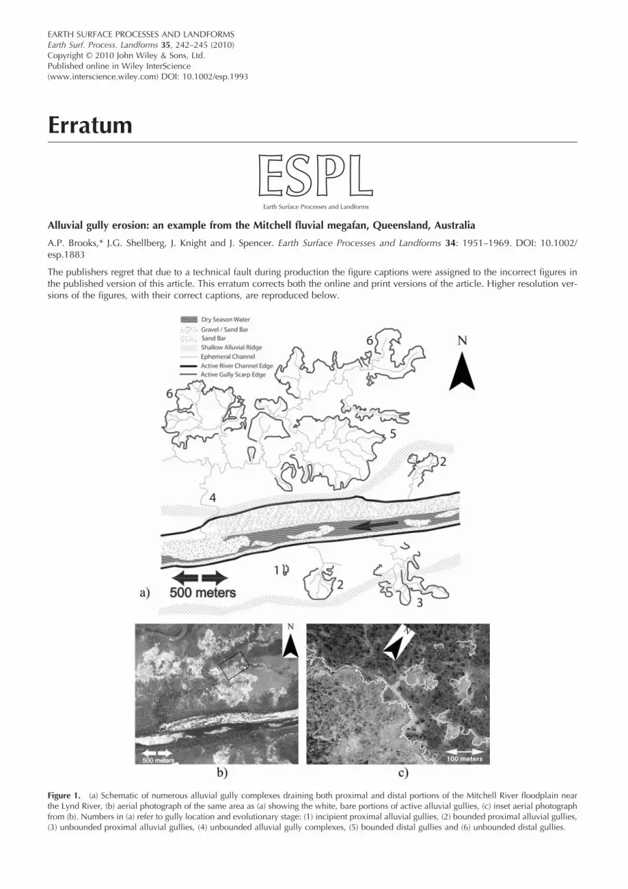
EARTH SURFACE PROCESSES AND LANDFORMSEarth Surf. Process. Landforms 35, 242–245 (2010)Copyright © 2010 John Wiley & Sons, Ltd.Published online in Wiley InterScience(www.interscience.wiley.com) DOI: 10.1002/esp.1993
Erratum
Alluvial gully erosion: an example from the Mitchell fl uvial megafan, Queensland, Australia
A.P. Brooks,* J.G. Shellberg, J. Knight and J. Spencer. Earth Surface Processes and Landforms 34: 1951–1969. DOI: 10.1002/esp.1883
The publishers regret that due to a technical fault during production the fi gure captions were assigned to the incorrect fi gures in the published version of this article. This erratum corrects both the online and print versions of the article. Higher resolution ver-sions of the fi gures, with their correct captions, are reproduced below.
Figure 1. (a) Schematic of numerous alluvial gully complexes draining both proximal and distal portions of the Mitchell River fl oodplain near the Lynd River, (b) aerial photograph of the same area as (a) showing the white, bare portions of active alluvial gullies, (c) inset aerial photograph from (b). Numbers in (a) refer to gully location and evolutionary stage: (1) incipient proximal alluvial gullies, (2) bounded proximal alluvial gullies, (3) unbounded proximal alluvial gullies, (4) unbounded alluvial gully complexes, (5) bounded distal gullies and (6) unbounded distal gullies.

ERRATUM 243
Copyright © 2010 John Wiley & Sons, Ltd. Earth Surf. Process. Landforms, Vol. 35, 242–245 (2010)
Figure 2. (a) Location and evolution of the Mitchell and Gilbert megafans from the Pliocene to Holocene [modifi ed from Grimes and Doutch (1978)], (b) MODIS image of the Mitchell/Staaten/Gilbert River megafans during fl ood, representing the inset dashed rectangular area in (a). Note partial cloud cover in lower left. Area represented in (b) is indicated by the box in the inset location map. This fi gure is available in colour online at www.interscience.wiley.com/journal/espl
Figure 3. Alluvial gully distribution and density (in m2/km2) across the Mitchell fl uvial megafan. The density grid resolution is 1 km2 pixels. Dashed line is the Palmerville fault.

244 ERRATUM
Copyright © 2010 John Wiley & Sons, Ltd. Earth Surf. Process. Landforms, Vol. 35, 242–245 (2010)
Figure 4. Gully pixel (15 × 15 m) frequency from ASTER delineation in relation to main channels.
Figure 6. Longitudinal profi le of the Mitchell River thalweg and adjacent megafan surface (fl oodplain or terrace). Locations of the key tributary confl uences are noted as distances upstream (km), as are current and past fl uvial megafan apexes.
Figure 5. Gully pixel frequency from ASTER delineation in relation to pixel elevation determined from the 30 m SRTM DEM. Pixel elevation is closely correlated with distance from mouth, and hence this fi gure can be viewed as a type of longitudinal profi le.

ERRATUM 245
Copyright © 2010 John Wiley & Sons, Ltd. Earth Surf. Process. Landforms, Vol. 35, 242–245 (2010)
Figure 7. Relationship between measured gully head scarp height (SH) and adjacent fl oodplain surface elevation (EL) as derived from the 30 m SRTM DEM.
Figure 8. Longitudinal profi les of alluvial gully thalwegs between a main channel and adjacent fl oodplain. S = gully channel or fl oodplain slope. SH = scarp height.