aficio color 6010/6110 (cattleya, a257/a269) service manual
TRANSCRIPT

Aficio Color 6010/6110(Cattleya, A257/A269)
Service Manual
Issued March 30, 1999, Ricoh CO., LTD.

ø IMPORTANT SAFETY NOTICES
PREVENTION OF PHYSICAL INJURY
1. Before disassembling or assembling parts of the copier and peripherals,make sure that the copier power cord is unplugged.
2. The wall outlet should be near the copier and easily accessible.
3. Note that some components of the copier and the paper tray unit aresupplied with electrical voltage even if the main power switch is turned off.
4. If any adjustment or operation check has to be made with exterior covers offor open while the main switch is turned on, keep hands away from electrifiedor mechanically driven components.
5. If the Start key is pressed before the copier completes the warm-up period(the Start key starts blinking red and green alternatively), keep hands awayfrom the mechanical and the electrical components as the copier startsmaking copies as soon as the warm-up period is completed.
6. The inside and the metal parts of the fusing unit become extremely hot whilethe copier is operating. Be careful to avoid touching those components withyour bare hands.
HEALTH SAFETY CONDITIONS
1. Never operate the copier without the ozone filters installed.
2. Always replace the ozone filters with the specified ones at the specifiedintervals.
3. Toner and developer are non-toxic, but if you get either of them in your eyesby accident, it may cause temporary eye discomfort. Try to remove with eyedrops or flush with water as first aid. If unsuccessful, get medical attention.
OBSERVANCE OF ELECTRICAL SAFETY STANDARDS
1. The copier and its peripherals must be installed and maintained by acustomer service representative who has completed the training course onthose models.
2. The NVRAM on the system control board has a lithium battery which canexplode if replaced incorrectly. Replace the NVRAM only with an identicalone. The manufacturer recommends replacing the entire NVRAM. Do notrecharge or burn this battery. Used NVRAM must be handled in accordancewith local regulations.
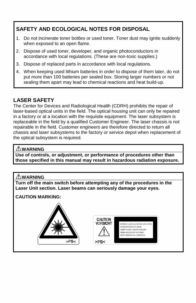
SAFETY AND ECOLOGICAL NOTES FOR DISPOSAL
1. Do not incinerate toner bottles or used toner. Toner dust may ignite suddenlywhen exposed to an open flame.
2. Dispose of used toner, developer, and organic photoconductors inaccordance with local regulations. (These are non-toxic supplies.)
3. Dispose of replaced parts in accordance with local regulations.
4. When keeping used lithium batteries in order to dispose of them later, do notput more than 100 batteries per sealed box. Storing larger numbers or notsealing them apart may lead to chemical reactions and heat build-up.
LASER SAFETYThe Center for Devices and Radiological Health (CDRH) prohibits the repair oflaser-based optical units in the field. The optical housing unit can only be repairedin a factory or at a location with the requisite equipment. The laser subsystem isreplaceable in the field by a qualified Customer Engineer. The laser chassis is notrepairable in the field. Customer engineers are therefore directed to return allchassis and laser subsystems to the factory or service depot when replacement ofthe optical subsystem is required.
øWARNINGUse of controls, or adjustment, or performance of procedures other thanthose specified in this manual may result in hazardous radiation exposure.
øWARNINGTurn off the main switch before attempting any of the procedures in theLaser Unit section. Laser beams can seriously damage your eyes.
CAUTION MARKING:
i
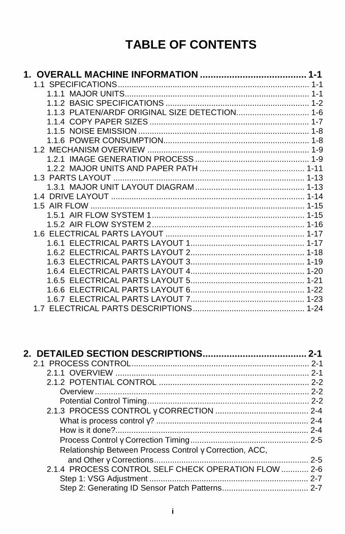
TABLE OF CONTENTS
1. OVERALL MACHINE INFORMATION ........................................ 1-11.1 SPECIFICATIONS.................................................................................... 1-1
1.1.1 MAJOR UNITS................................................................................. 1-11.1.2 BASIC SPECIFICATIONS ............................................................... 1-21.1.3 PLATEN/ARDF ORIGINAL SIZE DETECTION................................ 1-61.1.4 COPY PAPER SIZES ...................................................................... 1-71.1.5 NOISE EMISSION ........................................................................... 1-81.1.6 POWER CONSUMPTION................................................................ 1-8
1.2 MECHANISM OVERVIEW ....................................................................... 1-91.2.1 IMAGE GENERATION PROCESS .................................................. 1-91.2.2 MAJOR UNITS AND PAPER PATH .............................................. 1-11
1.3 PARTS LAYOUT .................................................................................... 1-131.3.1 MAJOR UNIT LAYOUT DIAGRAM................................................ 1-13
1.4 DRIVE LAYOUT ..................................................................................... 1-141.5 AIR FLOW .............................................................................................. 1-15
1.5.1 AIR FLOW SYSTEM 1................................................................... 1-151.5.2 AIR FLOW SYSTEM 2................................................................... 1-16
1.6 ELECTRICAL PARTS LAYOUT ............................................................. 1-171.6.1 ELECTRICAL PARTS LAYOUT 1.................................................. 1-171.6.2 ELECTRICAL PARTS LAYOUT 2.................................................. 1-181.6.3 ELECTRICAL PARTS LAYOUT 3.................................................. 1-191.6.4 ELECTRICAL PARTS LAYOUT 4.................................................. 1-201.6.5 ELECTRICAL PARTS LAYOUT 5.................................................. 1-211.6.6 ELECTRICAL PARTS LAYOUT 6.................................................. 1-221.6.7 ELECTRICAL PARTS LAYOUT 7.................................................. 1-23
1.7 ELECTRICAL PARTS DESCRIPTIONS................................................. 1-24
2. DETAILED SECTION DESCRIPTIONS....................................... 2-12.1 PROCESS CONTROL.............................................................................. 2-1
2.1.1 OVERVIEW ..................................................................................... 2-12.1.2 POTENTIAL CONTROL .................................................................. 2-2
Overview .............................................................................................. 2-2Potential Control Timing....................................................................... 2-2
2.1.3 PROCESS CONTROL γ CORRECTION ......................................... 2-4What is process control γ? ................................................................... 2-4How is it done?..................................................................................... 2-4Process Control γ Correction Timing.................................................... 2-5Relationship Between Process Control γ Correction, ACC, and Other γ Corrections.................................................................... 2-5
2.1.4 PROCESS CONTROL SELF CHECK OPERATION FLOW ............ 2-6Step 1: VSG Adjustment ...................................................................... 2-7Step 2: Generating ID Sensor Patch Patterns...................................... 2-7
ii
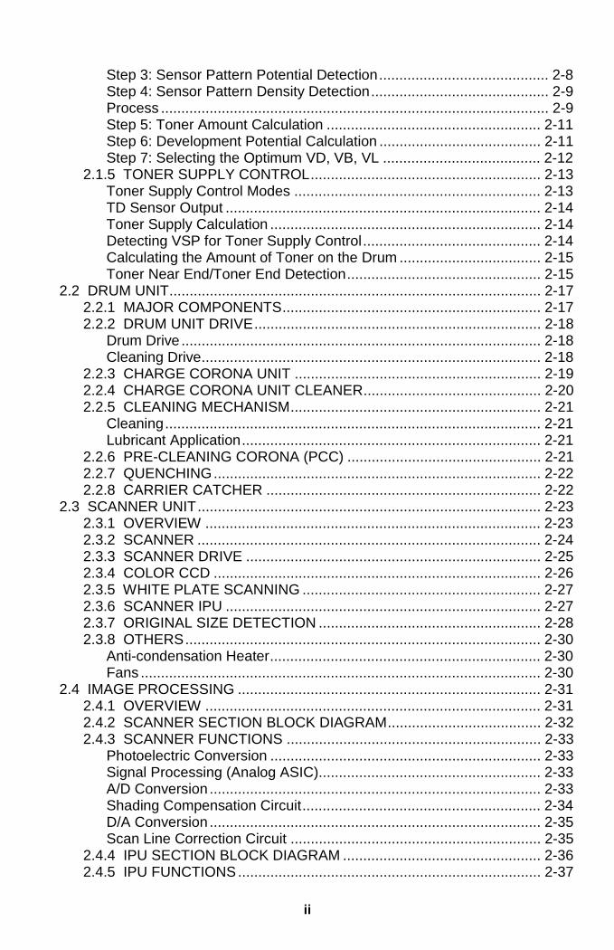
Step 3: Sensor Pattern Potential Detection.......................................... 2-8Step 4: Sensor Pattern Density Detection............................................ 2-9Process ................................................................................................ 2-9Step 5: Toner Amount Calculation ..................................................... 2-11Step 6: Development Potential Calculation ........................................ 2-11Step 7: Selecting the Optimum VD, VB, VL ....................................... 2-12
2.1.5 TONER SUPPLY CONTROL......................................................... 2-13Toner Supply Control Modes ............................................................. 2-13TD Sensor Output .............................................................................. 2-14Toner Supply Calculation ................................................................... 2-14Detecting VSP for Toner Supply Control............................................ 2-14Calculating the Amount of Toner on the Drum ................................... 2-15Toner Near End/Toner End Detection................................................ 2-15
2.2 DRUM UNIT............................................................................................ 2-172.2.1 MAJOR COMPONENTS................................................................ 2-172.2.2 DRUM UNIT DRIVE....................................................................... 2-18
Drum Drive ......................................................................................... 2-18Cleaning Drive.................................................................................... 2-18
2.2.3 CHARGE CORONA UNIT ............................................................. 2-192.2.4 CHARGE CORONA UNIT CLEANER............................................ 2-202.2.5 CLEANING MECHANISM.............................................................. 2-21
Cleaning............................................................................................. 2-21Lubricant Application.......................................................................... 2-21
2.2.6 PRE-CLEANING CORONA (PCC) ................................................ 2-212.2.7 QUENCHING................................................................................. 2-222.2.8 CARRIER CATCHER .................................................................... 2-22
2.3 SCANNER UNIT..................................................................................... 2-232.3.1 OVERVIEW ................................................................................... 2-232.3.2 SCANNER ..................................................................................... 2-242.3.3 SCANNER DRIVE ......................................................................... 2-252.3.4 COLOR CCD ................................................................................. 2-262.3.5 WHITE PLATE SCANNING ........................................................... 2-272.3.6 SCANNER IPU .............................................................................. 2-272.3.7 ORIGINAL SIZE DETECTION ....................................................... 2-282.3.8 OTHERS........................................................................................ 2-30
Anti-condensation Heater................................................................... 2-30Fans ................................................................................................... 2-30
2.4 IMAGE PROCESSING ........................................................................... 2-312.4.1 OVERVIEW ................................................................................... 2-312.4.2 SCANNER SECTION BLOCK DIAGRAM...................................... 2-322.4.3 SCANNER FUNCTIONS ............................................................... 2-33
Photoelectric Conversion ................................................................... 2-33Signal Processing (Analog ASIC)....................................................... 2-33A/D Conversion .................................................................................. 2-33Shading Compensation Circuit........................................................... 2-34D/A Conversion .................................................................................. 2-35Scan Line Correction Circuit .............................................................. 2-35
2.4.4 IPU SECTION BLOCK DIAGRAM ................................................. 2-362.4.5 IPU FUNCTIONS........................................................................... 2-37
iii
Scanner γ Conversion and Picture Element Correction...................... 2-37ACS (Auto Color Selection)................................................................ 2-39Automatic Original Type Selection ..................................................... 2-40Image Separation............................................................................... 2-41Filtering and Color Conversion........................................................... 2-42Magnification Processing ................................................................... 2-46Image Creation................................................................................... 2-47Gradation Processing......................................................................... 2-49Area Manipulation Functions.............................................................. 2-52CPU ................................................................................................... 2-52IPU Board Test................................................................................... 2-52
2.5 LASER EXPOSURE ............................................................................... 2-532.5.1 OVERVIEW ................................................................................... 2-532.5.2 LD UNIT......................................................................................... 2-54
LD Safety Switch................................................................................ 2-54LD Unit Configuration......................................................................... 2-55Auto Power Control (APC) ................................................................. 2-56
2.5.3 LASER OPTICS SYSTEM ............................................................. 2-57Cylindrical Lens.................................................................................. 2-57Polygon Mirror.................................................................................... 2-57f θ Lenses and the BTL ...................................................................... 2-58Laser Synchronization Mechanism .................................................... 2-58Laser Exposure Control ..................................................................... 2-59Multibeam Laser Exposure ................................................................ 2-60Laser Diode Control Board Functions ................................................ 2-60
2.6 DEVELOPMENT UNIT ........................................................................... 2-612.6.1 OVERVIEW ................................................................................... 2-612.6.2 REVOLVER MECHANISM............................................................. 2-62
Revolver Drive.................................................................................... 2-63Revolver Home Position Detection..................................................... 2-64
2.6.3 DEVELOPMENT MECHANISM..................................................... 2-652.6.4 DEVELOPMENT DRIVE................................................................ 2-662.6.5 DEVELOPER AGITATION............................................................. 2-662.6.6 TONER AGITATION...................................................................... 2-672.6.7 DEVELOPMENT BIAS................................................................... 2-672.6.8 TD SENSOR NONCONTACT COUPLER ..................................... 2-682.6.9 TONER SUPPLY MECHANISM .................................................... 2-692.6.10 TONER CARTRIDGE DETECTION............................................. 2-702.6.11 TONER CARTRIDGE SHUTTER LOCK PIN............................... 2-702.6.12 INCORRECT TONER INSTALLATION PREVENTION ............... 2-702.6.13 TONER END SENSOR................................................................ 2-712.6.14 TONER END RECOVERY........................................................... 2-722.6.15 TONER LOOSENING .................................................................. 2-732.6.16 REVOLVER LOCK MECHANISM................................................ 2-74
2.7 TRANSFER BELT UNITS....................................................................... 2-752.7.1 OVERVIEW ................................................................................... 2-752.7.2 IMAGE TRANSFER BELT SECTION ............................................ 2-76
Image Transfer Belt Drive Mechanism ............................................... 2-76Belt Tension Release Mechanism...................................................... 2-77
iv
Image Transfer Belt Bias.................................................................... 2-78Belt Mark Sensor Mechanism ............................................................ 2-78Belt Cleaning Mechanism .................................................................. 2-79Cleaning Vacuum............................................................................... 2-81Toner Collection Mechanism.............................................................. 2-81
2.7.3 PAPER TRANSFER BELT SECTION............................................ 2-82Paper Transfer Unit Contact/Release Mechanism ............................. 2-82Paper Transfer Belt Drive................................................................... 2-82Paper Transfer Belt Cleaning............................................................. 2-83Paper Transfer Bias ........................................................................... 2-84Paper Transfer Belt Discharge........................................................... 2-85Paper Separation Mechanism............................................................ 2-85
2.8 PAPER FEED AND REGISTRATION SECTION.................................... 2-862.8.1 MAJOR COMPONENTS................................................................ 2-86
Diagram ............................................................................................. 2-862.8.2 PAPER TRAY SECTION ............................................................... 2-87
Paper Feed/Separation Mechanism................................................... 2-87Reverse Roller Release Mechanism.................................................. 2-87Paper Feed Operation........................................................................ 2-87Paper Lift Mechanism ........................................................................ 2-88Paper End Detection .......................................................................... 2-89Paper Near End Detection ................................................................. 2-89
2.8.3 BY-PASS PAPER FEED SECTION............................................... 2-90By-pass Feed Table ........................................................................... 2-90By-pass Feed Unit.............................................................................. 2-90By-pass Paper End Sensor................................................................ 2-90By-pass Pick-up Roller Pressure........................................................ 2-91By-pass Pick-up/Reverse Solenoid Timing Chart............................... 2-92
2.8.4 PAPER FEED DRIVE .................................................................... 2-93Tray Feed Unit Drive .......................................................................... 2-93Registration Roller Drive .................................................................... 2-93By-pass Feed Unit Drive .................................................................... 2-93
2.9 TRANSPORT, FUSING, AND EXIT........................................................ 2-942.9.1 MAJOR COMPONENTS................................................................ 2-942.9.2 DRIVE MECHANISM ..................................................................... 2-952.9.3 FUSING OVERVIEW ..................................................................... 2-962.9.4 FUSING TEMPERATURE CONTROL........................................... 2-972.9.5 FUSING PRESSURE..................................................................... 2-972.9.6 OIL SUPPLY.................................................................................. 2-982.9.7 CLEANING MECHANISM.............................................................. 2-982.9.8 PAPER EXIT AND PAPER INVERSION ....................................... 2-99
Paper Exit Mechanism ....................................................................... 2-99Junction Gate Mechanism.................................................................. 2-99Paper Exit Cover ................................................................................ 2-99
2.10 DUPLEX TRAY................................................................................... 2-1002.10.1 OVERVIEW ............................................................................... 2-1002.10.2 DRIVE MECHANISM ................................................................. 2-1012.10.3 PAPER FEED INTO THE DUPLEX TRAY................................. 2-102
Duplex Stacking ............................................................................... 2-102
v
Paper Feed from the Duplex Tray .................................................... 2-102Duplex Entrance to Duplex Tray ...................................................... 2-103
2.10.4 JOGGER MECHANISM............................................................. 2-1042.10.5 PAPER FEED FROM THE DUPLEX TRAY............................... 2-105
Bottom Plate Lift Mechanism ........................................................... 2-1052.10.6 PAPER FEED-OUT MECHANISM............................................. 2-106
2.11 SYSTEM CONFIGURATION.............................................................. 2-1072.11.1 CONFIGURATION..................................................................... 2-1072.11.2 NORMAL COPY MODE............................................................. 2-108
Main Power Switch Off State ........................................................... 2-108Power-off (Sleep) State.................................................................... 2-108Copier Modes................................................................................... 2-109
2.11.3 OPERATION PANEL ................................................................. 2-1102.11.4 PRINTER CONTROLLER INTERFACE .................................... 2-111
3. INSTALLATION PROCEDURES................................................. 3-13.1 INSTALLATION REQUIREMENTS .......................................................... 3-1
3.1.1 DIMENSIONS .................................................................................. 3-13.1.2 ENVIRONMENT .............................................................................. 3-2
Environmental Requirements............................................................... 3-2Minimum Space Requirements ............................................................ 3-3Power Requirements............................................................................ 3-4
3.2 COPIER.................................................................................................... 3-53.2.1 ACCESSORY CHECK..................................................................... 3-53.2.2 PREPERATION ............................................................................... 3-63.2.3 DEVELOPER INSTALLATION....................................................... 3-103.2.4 LOADING TONER CARTRIDGES................................................. 3-143.2.5 FUSING UNIT ................................................................................ 3-163.2.6 DEFAULT SETTINGS AND OPERATION CHECKS ..................... 3-173.2.7 HEIGHT ADJUSTMENT ................................................................ 3-193.2.8 COUNTER DISPLAY SETTING...................................................... 3-193.2.9 RESETTING THE ELECTRONIC TOTAL COUNTER................... 3-193.2.10 PREPARATION FOR TRANSPORT............................................ 3-20
3.3 PLATEN COVER (A749-01) ................................................................... 3-213.3.1 INSTALLATION ............................................................................. 3-21
3.4 ARDF (A663) .......................................................................................... 3-223.4.1 ACCESSORY CHECK................................................................... 3-223.4.2 INSTALLATION ............................................................................. 3-23
3.5 SORTER STAPLER (A831).................................................................... 3-243.5.1 INSTALLATION ............................................................................. 3-24
3.6 LCT (A683) ............................................................................................. 3-293.6.1 INSTALLATION ............................................................................. 3-29
3.7 LCT ADAPTER (A840) ........................................................................... 3-303.7.1 INSTALLATION ............................................................................. 3-30
3.8 FILM PROJECTOR TABLE (A702-19) ................................................... 3-363.8.1 INSTALLATION ............................................................................. 3-36
vi
3.9 FILM PROJECTOR UNIT(A846) ............................................................ 3-383.9.1 ACCESSORY CHECK................................................................... 3-383.9.2 INSTALLATION ............................................................................. 3-39
3.10 KEY COUNTER HOLDER.................................................................... 3-463.11 USER CODE SETTING........................................................................ 3-47
4. SERVICE TABLES...................................................................... 4-14.1 SERVICE PROGRAM (SP) MODES ........................................................ 4-1
4.1.1 HOW TO ENTER AN SP MODE...................................................... 4-14.1.2 SP MODE TYPES............................................................................ 4-34.1.3 SP MODE CHART ........................................................................... 4-34.1.4 SP4-301 APS OPERATION CHECK DETAILS ............................... 4-34.1.5 TEST PATTERN.............................................................................. 4-54.1.6 SP5-803 INPUT CHECK.................................................................. 4-64.1.7 SP5-804 OUTPUT CHECK.............................................................. 4-94.1.8 SP5-955 PRINTER INTERNAL PATTERN.................................... 4-11
5-955-018: Internal Pattern Types...................................................... 4-114.2 USER TOOLS......................................................................................... 4-11
4.2.1 HOW TO ENTER USER TOOLS................................................... 4-114.2.2 DETAILED DESCRIPTION OF USER TOOLS.............................. 4-12
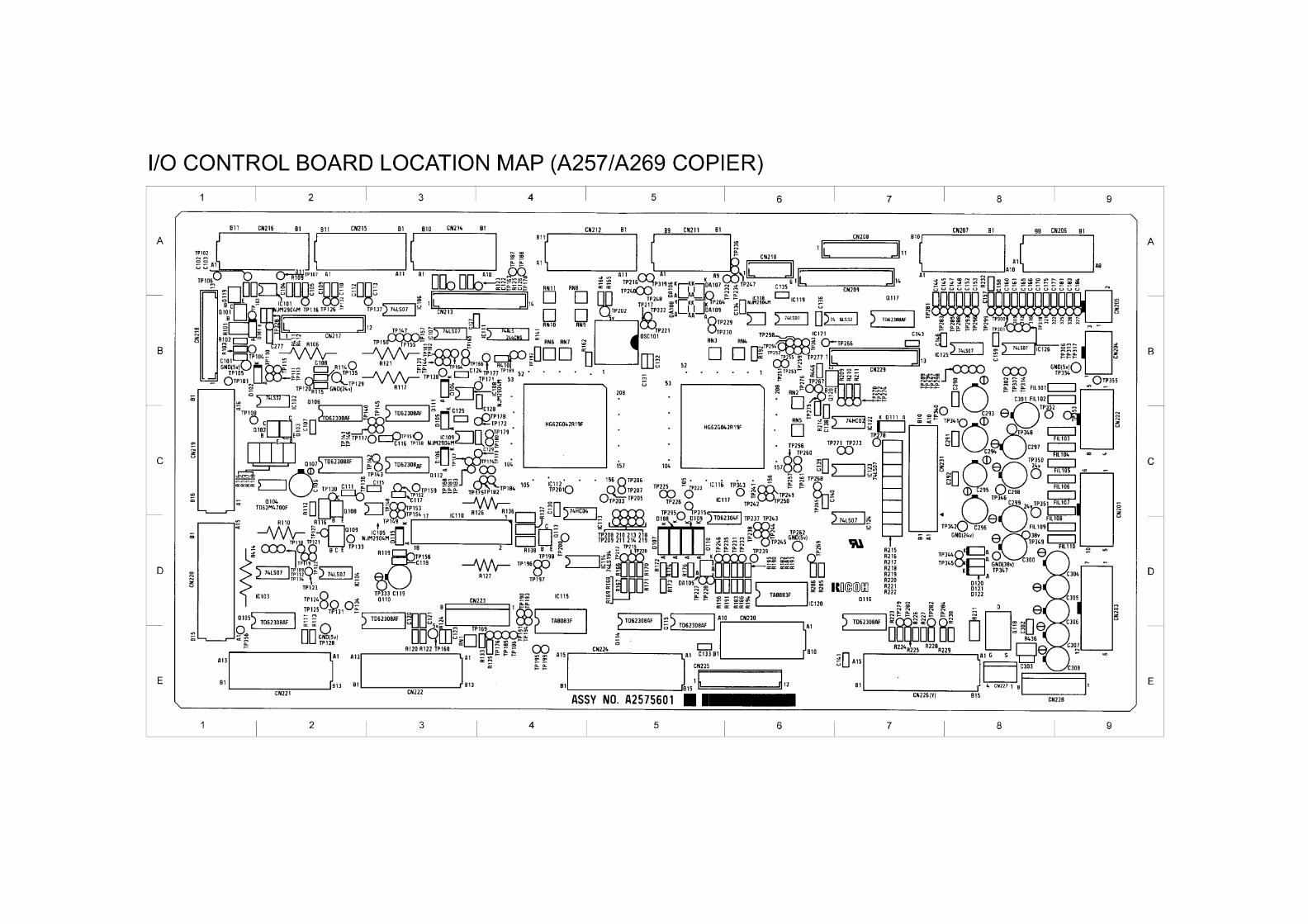
4.3 TP/SW/LED/FUSE.................................................................................. 4-124.3.1 MAIN CONTROL BOARD TEST PINS .......................................... 4-124.3.2 LD MAIN CONTROL BOARD TEST PINS..................................... 4-134.3.3 I/O CONTROL BOARD TEST PINS .............................................. 4-134.3.4 FUSE SPECIFICATIONS .............................................................. 4-194.3.5 LED/SW SPECIFICATIONS OF SCANNER IPU BOARD ............. 4-20
LED Specifications ............................................................................. 4-20SW Specifications .............................................................................. 4-20
5. PREVENTIVE MAINTENANCE ................................................... 5-15.1 PM PROCEDURES .................................................................................. 5-1
5.1.1 PM-RELATED COUNTERS............................................................. 5-1SP7-803 (PM Counter Display) ............................................................ 5-1
5.1.2 REGULAR PREVENTIVE MAINTENANCE FLOW DIAGRAM........ 5-45.2 REGULAR PM ITEMS .............................................................................. 5-7
5.2.1 REGULAR PM TABLE..................................................................... 5-7Peripherals......................................................................................... 5-11
vii
6. REPLACEMENT AND ADJUSTMENT........................................ 6-16.1 PM-RELATED COUNTERS...................................................................... 6-16.2 SERVICE REMARKS ............................................................................... 6-16.3 COVERS AND FILTERS .......................................................................... 6-2
6.3.1 UPPER AND LOWER FRONT COVER........................................... 6-26.3.2 RIGHT-SIDE FRONT COVER AND RIGHT EDGE COVER............ 6-26.3.3 INNER COVERS.............................................................................. 6-36.3.4 REAR COVERS............................................................................... 6-36.3.5 LEFT COVERS................................................................................ 6-46.3.6 EXPOSURE GLASS ........................................................................ 6-46.3.7 OPERATION PANEL ....................................................................... 6-56.3.8 USED TONER TANK....................................................................... 6-56.3.9 CHARGE CORONA FILTER............................................................ 6-66.3.10 DUST AND OZONE FILTERS ....................................................... 6-66.3.11 SCANNER FILTER........................................................................ 6-76.3.12 REVOLVER FILTER ...................................................................... 6-76.3.13 INNER COVER FILTER................................................................. 6-86.3.14 FUSING UNIT FILTER................................................................... 6-8
6.4 UNIT REMOVAL....................................................................................... 6-96.4.1 REVOLVER/DRUM DRAWER......................................................... 6-96.4.2 DRUM UNIT REMOVAL ................................................................ 6-106.4.3 REINSTALLING THE REVOLVER/DRUM DRAWER.................... 6-116.4.4 IMAGE TRANSFER BELT UNIT REMOVAL ................................. 6-12
Reinstalling the Image Transfer Belt Unit ........................................... 6-136.4.5 PAPER TRANSFER UNIT REMOVAL........................................... 6-146.4.6 REMOVING THE FUSING UNIT ................................................... 6-15
6.5 DRUM UNIT............................................................................................ 6-166.5.1 DRUM REPLACEMENT ................................................................ 6-16
Post-replacement Procedure ............................................................. 6-176.5.2 CLEANING BLADE REPLACEMENT ............................................ 6-186.5.3 CLEANING BRUSH REPLACEMENT ........................................... 6-196.5.4 LUBRICANT BAR REPLACEMENT .............................................. 6-196.5.5 BIAS ROLLER BLADE REPLACEMENT....................................... 6-206.5.6 CHARGE GRID AND CORONA WIRE REPLACEMENT .............. 6-206.5.7 PCC REPLACEMENT ................................................................... 6-216.5.8 DRUM POTENTIAL SENSOR REPLACEMENT ........................... 6-226.5.9 ID SENSOR REPLACEMENT ....................................................... 6-23
6.6 SCANNER UNIT..................................................................................... 6-246.6.1 EXPOSURE LAMP REPLACEMENT ............................................ 6-246.6.2 SBU REPLACEMENT.................................................................... 6-256.6.3 OPENING THE SCANNER UNIT .................................................. 6-266.6.4 SCANNER IPU MAIN/SUB BOARD REPLACEMENT................... 6-286.6.5 SCANNER WIRE REPLACEMENT ............................................... 6-296.6.6 APS AND H.P. SENSOR REPLACEMENT ................................... 6-32
6.7 COPY IMAGE ADJUSTMENT ................................................................ 6-336.7.1 PRINTER γ ADJUSTMENT............................................................ 6-33
Auto Color Calibration (ACC) ............................................................. 6-33KCMY Color Balance Adjustment ...................................................... 6-33
viii
ACC Target Modification .................................................................... 6-366.7.2 MAIN SCAN POSITION DOT CORRECTION ............................... 6-37
6.8 LASER OPTICS SECTION..................................................................... 6-406.8.1 POLYGON MIRROR MOTOR REPLACEMENT............................ 6-406.8.2 LASER SYNCHRONIZING DETECTOR REPLACEMENT............ 6-426.8.3 LD UNIT REPLACEMENT ............................................................. 6-42
LD Pitch Check and Adjustment]........................................................ 6-436.8.4 SQUARENESS ADJUSTMENT..................................................... 6-476.8.5 LD CONTROL BOARD REPLACEMENT ...................................... 6-49
6.9 DEVELOPMENT UNIT ........................................................................... 6-506.9.1 DEVELOPER REPLACEMENT ..................................................... 6-50
Developer Collection .......................................................................... 6-506.9.2 DEVELOPER INSTALLATION....................................................... 6-536.9.3 DEVELOPMENT UNIT REPLACEMENT....................................... 6-586.9.4 TONER CATCH COVER CLEANING ............................................ 6-596.9.5 REVOLVER MOTOR REPLACEMENT ......................................... 6-606.9.6 TONER DENSITY SENSOR REPLACEMENT.............................. 6-616.9.7 TD SENSOR NONCONTACT COUPLER REPLACEMENT.......... 6-62
Main Unit Element.............................................................................. 6-62TD Sensor Interface (I/F) Board......................................................... 6-63
6.8 IMAGE TRANSFER SECTION............................................................... 6-656.8.1 IMAGE TRANSFER BELT REPLACEMENT ................................. 6-656.8.2 IMAGE TRANSFER BELT BLADE REPLACEMENT..................... 6-676.8.3 TRANSFER BELT LUBRICANT BAR AND LUBRICANT BRUSH REPLACEMENT .............................................................. 6-686.8.4 PAPER TRANSFER BELT REPLACEMENT................................. 6-696.8.5 PAPER TRANSFER BELT BLADE/CLEANING BRUSH REPLACEMENT............................................................................ 6-696.8.6 BACK BRUSH REPLACEMENT.................................................... 6-706.8.7 PAPER TRANSFER BELT DISCHARGE CORONA WIRE REPLACEMENT............................................................................ 6-706.8.8 PAPER DISCHARGE CORONA WIRE REPLACEMENT.............. 6-71
6.9 PAPER FEED AND REGISTRATION SECTION.................................... 6-726.9.1 BY-PASS FEED TABLE REMOVAL .............................................. 6-726.9.2 BY-PASS FEED PAPER WIDTH SENSOR REPLACEMENT ....... 6-736.9.3 BY-PASS PICK-UP ROLLER REPLACEMENT............................. 6-746.9.4 BY-PASS FEED ROLLER REPLACEMENT.................................. 6-746.9.5 BY-PASS SEPARATION ROLLER REPLACEMENT .................... 6-756.9.6 BY-PASS PAPER FEED UNIT REMOVAL.................................... 6-756.9.7 BY-PASS PAPER FEED UNIT INSTALLATION............................ 6-766.9.8 REGISTRATION SENSOR REPLACEMENT ................................ 6-786.9.9 PAPER TRAY ROLLER REPLACEMENT ..................................... 6-786.9.10 PAPER FEED UNIT AND PAPER FEED CLUTCH REPLACEMENT .......................................................................... 6-796.9.11 COPY IMAGE AREA ADJUSTMENT .......................................... 6-80
PAPER TRANSPORT, FUSING, AND PAPER EXIT......................... 6-836.10.1 TRANSPORT UNIT REMOVAL................................................... 6-836.10.2 FUSING UNIT TOP COVER REMOVAL ..................................... 6-836.10.3 OIL SUPPLY UNIT REPLACEMENT AND CLEANING ............... 6-84
ix
6.10.4 HOT ROLLER BLADE REPLACEMENT ..................................... 6-856.10.5 CLEANING THE CLEANING ROLLER SCRAPER...................... 6-866.10.6 FUSING THERMOFUSE AND THERMISTOR REPLACEMENT 6-866.10.7 FUSING UNIT DISASSEMBLY.................................................... 6-876.10.8 FUSING LAMP REPLACEMENT................................................. 6-886.10.9 HOT ROLLER REPLACEMENT .................................................. 6-886.10.10 HOT ROLLER CLEANING ROLLER CLEANING ...................... 6-896.10.11 PRESSURE ROLLER LAMP/ROLLER REPLACEMENT .......... 6-896.10.12 PRESSURE THERMOFUSE AND THERMISTOR REPLACEMENT........................................................................ 6-906.10.13 PRESSURE CLEANING ROLLER CLEANING ......................... 6-906.10.14 NIP BAND WIDTH ADJUSTMENT ............................................ 6-916.10.15 CAUTIONS TO BE TAKEN WHEN USING A FUSING UNIT THAT HAS BEEN IN STOCK FOR A LONG PERIOD .............. 6-92
6.11 DUPLEX UNIT ...................................................................................... 6-936.11.1 DUPLEX UNIT REMOVAL........................................................... 6-936.11.2 SEPARATION ROLLER REPLACEMENT................................... 6-936.11.3 FEED ROLLER REPLACEMENT ................................................ 6-946.11.4 DUPLEX FEED MOTOR REPLACEMENT.................................. 6-95
6.12 SYSTEM AND ELECTRONICS ............................................................ 6-976.12.1 SOFTWARE UPDATE USING AN IC CARD ............................... 6-97
Care of the IC Card ............................................................................ 6-97Upgrading the Main Control Board Software...................................... 6-97Upgrading the Scanner IPU Software ................................................ 6-98NV-RAM Uploading and Downloading ............................................. 6-101Upload/download procedure ............................................................ 6-101
6.12.2 RAM CLEAR.............................................................................. 6-102RAM Clear Procedure ...................................................................... 6-102
6.12.3 MAIN CONTROL BOARD.......................................................... 6-103Main Control Board Replacement Procedure................................... 6-103
6.12.4 COUNTERS............................................................................... 6-104About the Total Counter ................................................................... 6-104Mechanical Counter ......................................................................... 6-104NV-RAM Replacement Procedure ................................................... 6-105
6.12.5 TOUCH PANEL CALIBRATION................................................. 6-106
7. TROUBLESHOOTING................................................................. 7-17.1 PROCESS CONTROL ERROR CONDITIONS ........................................ 7-1
7.1.1 PROCESS CONTROL SELF CHECK RESULTS (SP3-975-00)...... 7-17.1.2 DEVELOPER SETUP RESULTS (SP3-964-00) .............................. 7-2
“Developer Agitation (SP2-225)” OPERATION FLOW ........................ 7-37.1.3 TD SENSOR INITIALIZATION RESULTS (SP3-005-006)............... 7-37.1.4 SELF-CHECK PROCESS CONTROL RELATED SCS ................... 7-4
SC385: Vsg Adjustment Error .............................................................. 7-47.2 SC CODE TABLE ..................................................................................... 7-47.3 DRUM LIGHT FATIGUE............................................................................ 7-5
x
OPTIONS
ARDF (A663)
1. SPECIFICATIONS.................................................................A663-1
2. COMPONENT LAYOUT ........................................................A663-22.1 MECHANICAL COMPONENTS.......................................................... A663-22.2 ELECTRICAL COMPONENTS ........................................................... A663-3
3. ELECTRICAL COMPONENT DESCRIPTION.......................A663-4
4. DETAILED DESCRIPTIONS .................................................A663-54.1 ORIGINAL PICK-UP MECHANISM .................................................... A663-54.2 SEPARATION AND PAPER FEED MECHANISM.............................. A663-64.3 FRICTION BELT DRIVE MECHANISM .............................................. A663-74.4 ORIGINAL SIZE DETECTION ............................................................ A663-84.5 PAPER TRANSPORT MECHANISM.................................................. A663-94.6 THICK/THIN ORIGINAL MODES ..................................................... A663-104.7 ORIGINAL FEED-OUT MECHANISM............................................... A663-114.8 TWO-SIDED ORIGINAL FEED MECHANISM.................................. A663-12
5. TIMING CHARTS ................................................................A663-135.1 A4 SIDEWAYS: 1 SIDED ORIGINAL ............................................... A663-135.2 COMBINE 2 ORIGINAL MODE ........................................................ A663-145.3 A4 SIDEWAYS: DUPLEX ................................................................. A663-15
6. SERVICE TABLES..............................................................A663-166.1 DIP SWITCHES................................................................................ A663-166.2 VARIABLE RESISTORS................................................................... A663-176.3 LED................................................................................................... A663-176.4 FUSE ................................................................................................ A663-17
7. REPLACEMENT AND ADJUSTMENT................................A663-187.1 TRANSPORT BELT REPLACEMENT.............................................. A663-187.2 FEED ROLLER REPLACEMENT ..................................................... A663-197.3 FRICTION BELT REPLACEMENT ................................................... A663-207.4 ORIGINAL SET AND WIDTH SENSOR REPLACEMENT................ A663-217.5 VERTICAL REGISTRATION ADJUSTMENT ................................... A663-22
7.5.1 ONE SIDED THIN ORIGINAL MODE ...................................... A663-227.5.2 TWO SIDED ORIGINAL MODE............................................... A663-23
7.6 SIDE-TO-SIDE REGISTRATION (DF POSITIONING) ADJUSTMENT.................................................................................. A663-24
xi
LCT (A683)
1. OVERALL MACHINE INFORMATION ..................................A683-11.1 SPECIFICATIONS.............................................................................. A683-11.2 MECHANICAL COMPONENT LAYOUT............................................. A683-21.3 ELECTRICAL COMPONENT LAYOUT .............................................. A683-31.4 ELECTRICAL COMPONENT DESCRIPTION.................................... A683-41.5 DRIVE LAYOUT ................................................................................. A683-5
2. DETAILED DESCRIPTIONS .................................................A683-62.1 PAPER FEED MECHANISM .............................................................. A683-62.2 TRAY LIFT AND PAPER HEIGHT DETECTION MECHANISM ......... A683-7
Tray lifting conditions ..................................................................... A683-7Tray lowering conditions ................................................................ A683-7
2.3 TRAY UNIT SLIDE MECHANISM....................................................... A683-8
3. SERVICE TABLES................................................................A683-93.1 DIP SWITCHES.................................................................................. A683-93.2 TEST POINTS .................................................................................... A683-93.3 SWITCHES......................................................................................... A683-93.4 FUSES................................................................................................ A683-9
4. REPLACEMENT AND ADJUSTMENT................................A683-104.1 COVER REPLACEMENT ................................................................. A683-10
Tray Cover ................................................................................... A683-10Front Cover .................................................................................. A683-10Rear Cover................................................................................... A683-10Right Lower Cover ....................................................................... A683-10Upper Cover................................................................................. A683-10
4.2 ROLLER REPLACEMENT................................................................ A683-114.2.1 PAPER FEED, SEPARATION, AND PICK-UP ROLLERS ...... A683-11
Pick-up Roller............................................................................... A683-11Paper Feed Roller ........................................................................ A683-11Separation Roller ......................................................................... A683-11
4.3 TRAY LIFT AND PAPER END SENSOR REPLACEMENT.............. A683-12Tray Lift Sensor............................................................................ A683-12Paper End Sensor........................................................................ A683-12
4.4 RELAY SENSOR REPLACEMENT .................................................. A683-134.5 SIDE FENCE POSITION CHANGE.................................................. A683-14
SORTER STAPLER (A831)
1. OVERALL MAHCINE INFORMATION ..................................A831-11.1 SPECIFICATIONS.............................................................................. A831-11.2 COMPONENT LAYOUT ..................................................................... A831-3
1.2.1 MECHANICAL COMPONENT LAYOUT.................................... A831-31.2.2 DRIVE LAYOUT......................................................................... A831-4
xii
2. DETAILED DESCRIPTION....................................................A831-52.1 BASIC OPERATION........................................................................... A831-5
2.1.1 NORMAL (PROOF MODE) AND SORT/STACK MODE............ A831-5Normal (Proof) Mode (From the Turn Gate Section to the Proof Tray) ............................................................... A831-5Sort Mode (From the Turn Gate Section to the Bins) ..................... A831-6Stack Mode (From the Turn Gate Section to the Bins)................... A831-7Reverse Mode (From the Turn Gate Section to the Bins) .............. A831-8
2.1.2 STAPLE MODE ......................................................................... A831-92.2 TURN GATE SECTION .................................................................... A831-112.3 BIN DRIVE MECHANISM................................................................. A831-122.4 BIN HOME POSITION...................................................................... A831-132.5 JOGGER SECTION.......................................................................... A831-142.6 BIN REAR PLATE DRIVE SECTION................................................ A831-152.7 GRIP ASSEMBLY............................................................................. A831-16
2.7.1 GRIP MOTOR.......................................................................... A831-172.7.2 GRIP SHIFT MOTOR .............................................................. A831-18
2.8 STAPLE UNIT................................................................................... A831-192.8.1 STAPLE UNIT DRIVE MECHANISM....................................... A831-192.8.2 STAPLER ................................................................................ A831-20
Staple Prohibit Conditions............................................................ A831-212.8.3 STAPLE UNIT PULLED-OUT MECHANISM ........................... A831-22
3. REPLACEMENTS AND ADJUSTMENTS ...........................A831-233.1 EXTERIOR COVER REMOVAL ....................................................... A831-233.2 STAPLER REMOVAL AND REINSTALLATION............................... A831-243.3 JOGGER PLATE REMOVAL AND INSTALLATIOIN........................ A831-25
Removal....................................................................................... A831-25Installation.................................................................................... A831-25
3.4 BINS REMOVAL............................................................................... A831-26Removal....................................................................................... A831-26Installation.................................................................................... A831-28
3.5 MAIN MOTOR REMOVAL................................................................ A831-303.6 GRIP ASSEMBLY REMOVAL .......................................................... A831-313.7 UPPER GRIP ASSEMBLY REMOVAL............................................. A831-323.8 GRIP SHIFT MOTOR REMOVAL..................................................... A831-333.9 HELICAL WHEELS REMOVAL ........................................................ A831-34
Removal....................................................................................... A831-34Front Helical Wheel...................................................................... A831-34Rear Helical Wheel ...................................................................... A831-35Installation.................................................................................... A831-36Rear Helical Wheel ...................................................................... A831-36Front Helical Wheel...................................................................... A831-37Alignment of the 2 Helical Wheels................................................ A831-38
3.10 GRIP MOTOR AND SENSORS REMOVAL ................................... A831-393.10.1 GRIP MOTOR/GRIP MOTOR HP SENSOR/GRIP SHIFT MOTOR HP SENSOR REMOVAL............................. A831-39
3.11 MAIN CONTROL BOARD REPLACEMENT................................... A831-40
xiii
4. SP MODE AND STAPLE POSITION ADJUSTMENT..........A831-414.1 SERVICE TABLES (MAIN CONTROL BOARD)............................... A831-41
4.1.1 DIP SWITCHES....................................................................... A831-41DIP 1 (Mode) SP Mode ................................................................ A831-41DIP 2 (Staple) Staple Position Adjustment (A) DIP 3 (Chuck) Staple Position Adjustment (B) ................................................. A831-41
FPU (A846)
1. SPECIFICATIONS.................................................................. A846-1
2. ELECTRICAL COMPONENT LAYOUT AND DESCRIPTIONS ........................................................... A846-2
3. SECTIONAL DESCRIPTIONS................................................ A846-33.1 OVERVIEW ........................................................................................ A846-33.2 SHADING ........................................................................................... A846-43.3 MIRROR UNIT.................................................................................... A846-5
APPENDIXAPPENDIX-1
SC CODE TABLEAPPENDIX-2
SP MODEAPPENDIX-3
POP-UP DISPALYSAPPENDIX-4
TIMING CHARTS
30 March 1999 SPECIFICATIONS
1-1
Ove
rall
Info
rmat
ion1. OVERALL MACHINE INFORMATION
1.1 SPECIFICATIONS
1.1.1 MAJOR UNITS
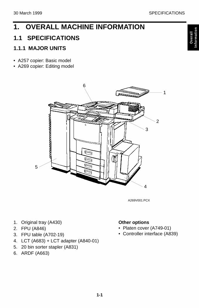
• A257 copier: Basic model• A269 copier: Editing model
1. Original tray (A430)2. FPU (A846)3. FPU table (A702-19)4. LCT (A683) + LCT adapter (A840-01)5. 20 bin sorter stapler (A831)6. ARDF (A663)
Other options• Platen cover (A749-01)• Controller interface (A839)
A269V001.PCX
5
3
2
1
4
6
SPECIFICATIONS 30 March 1999
1-2
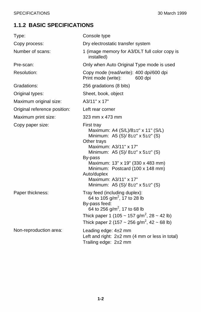
1.1.2 BASIC SPECIFICATIONS
Type: Console type
Copy process: Dry electrostatic transfer system
Number of scans: 1 (image memory for A3/DLT full color copy isinstalled)
Pre-scan: Only when Auto Original Type mode is used
Resolution: Copy mode (read/write): 400 dpi/600 dpiPrint mode (write): 600 dpi
Gradations: 256 gradations (8 bits)
Original types: Sheet, book, object
Maximum original size: A3/11" x 17"
Original reference position: Left rear corner
Maximum print size: 323 mm x 473 mm
Copy paper size: First trayMaximum: A4 (S/L)/81/2" x 11" (S/L)Minimum: A5 (S)/ 81/2" x 51/2" (S)
Other traysMaximum: A3/11" x 17"Minimum: A5 (S)/ 81/2" x 51/2" (S)
By-passMaximum: 13" x 19" (330 x 483 mm)Minimum: Postcard (100 x 148 mm)
Auto/duplexMaximum: A3/11" x 17"Minimum: A5 (S)/ 81/2" x 51/2" (S)
Paper thickness: Tray feed (including duplex):64 to 105 g/m2, 17 to 28 lb
By-pass feed:64 to 256 g/m2, 17 to 68 lb
Thick paper 1 (105 ~ 157 g/m2, 28 ~ 42 lb)Thick paper 2 (157 ~ 256 g/m2, 42 ~ 68 lb)
Non-reproduction area: Leading edge: 4±2 mmLeft and right: 2±2 mm (4 mm or less in total)Trailing edge: 2±2 mm
30 March 1999 SPECIFICATIONS
1-3
Ove
rall
Info
rmat
ion
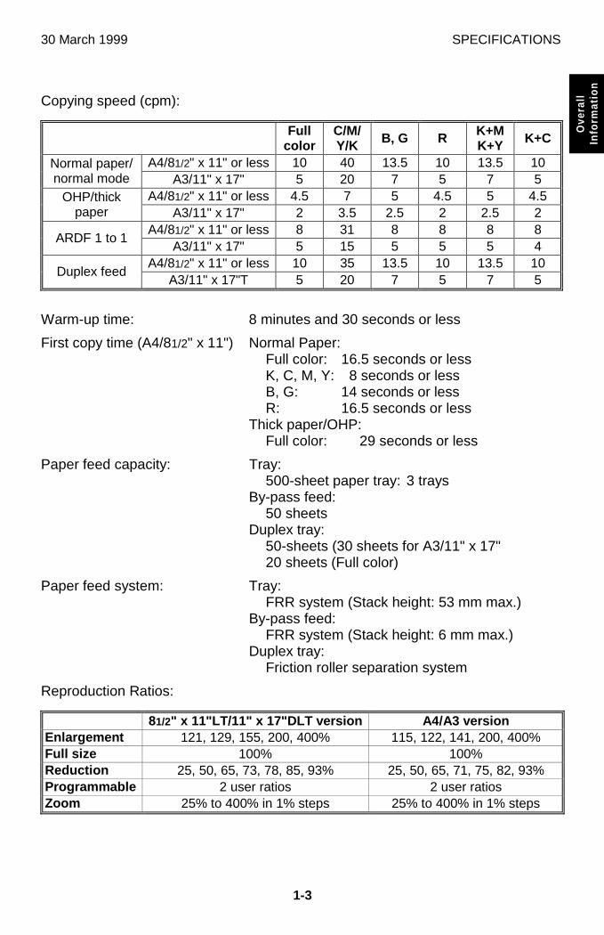
Copying speed (cpm):
Fullcolor
C/M/Y/K B, G R K+M
K+Y K+C
A4/81/2" x 11" or less 10 40 13.5 10 13.5 10Normal paper/normal mode A3/11" x 17" 5 20 7 5 7 5
A4/81/2" x 11" or less 4.5 7 5 4.5 5 4.5OHP/thickpaper A3/11" x 17" 2 3.5 2.5 2 2.5 2
A4/81/2" x 11" or less 8 31 8 8 8 8ARDF 1 to 1
A3/11" x 17" 5 15 5 5 5 4A4/81/2" x 11" or less 10 35 13.5 10 13.5 10
Duplex feedA3/11" x 17"T 5 20 7 5 7 5
Warm-up time: 8 minutes and 30 seconds or less
First copy time (A4/81/2" x 11") Normal Paper:Full color: 16.5 seconds or lessK, C, M, Y: 8 seconds or lessB, G: 14 seconds or lessR: 16.5 seconds or less
Thick paper/OHP:Full color: 29 seconds or less
Paper feed capacity: Tray:500-sheet paper tray: 3 trays
By-pass feed:50 sheets
Duplex tray:50-sheets (30 sheets for A3/11" x 17"20 sheets (Full color)
Paper feed system: Tray:FRR system (Stack height: 53 mm max.)
By-pass feed:FRR system (Stack height: 6 mm max.)
Duplex tray:Friction roller separation system
Reproduction Ratios:
81/2" x 11"LT/11" x 17"DLT version A4/A3 versionEnlargement 121, 129, 155, 200, 400% 115, 122, 141, 200, 400%Full size 100% 100%Reduction 25, 50, 65, 73, 78, 85, 93% 25, 50, 65, 71, 75, 82, 93%Programmable 2 user ratios 2 user ratiosZoom 25% to 400% in 1% steps 25% to 400% in 1% steps
SPECIFICATIONS 30 March 1999
1-4
Number of continuous copies: 1 to 999 sheets
Scanning system: 3-line 1-chip CCD sensor (400 dpi/5,000 pixels)
Light source: 1-halogen-lamp indirect lighting (frosted surface)
Print system: Twin laser beam, 600 dpi
Development system: 2-component magnetic brush
Drum cleaning system: Counter blade
Image Transfer system: Belt transfer system
Fusing system: Heat and pressure roller system with oil application
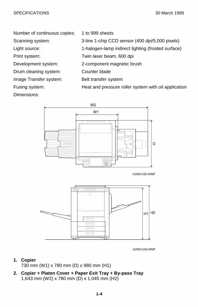
Dimensions:
1. Copier730 mm (W1) x 780 mm (D) x 980 mm (H1)
2. Copier + Platen Cover + Paper Exit Tray + By-pass Tray1,643 mm (W2) x 780 mm (D) x 1,045 mm (H2)
A269V155.WMF
A269V156.WMF
30 March 1999 SPECIFICATIONS
1-5
Ove
rall
Info
rmat
ion
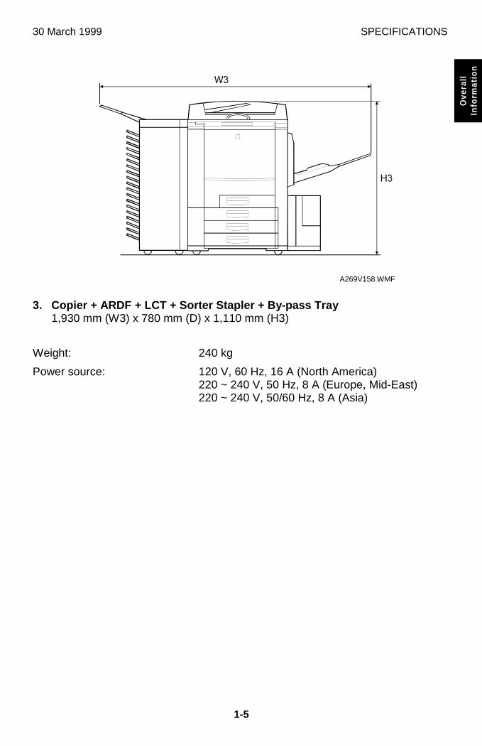
3. Copier + ARDF + LCT + Sorter Stapler + By-pass Tray1,930 mm (W3) x 780 mm (D) x 1,110 mm (H3)
Weight: 240 kg
Power source: 120 V, 60 Hz, 16 A (North America)220 ~ 240 V, 50 Hz, 8 A (Europe, Mid-East)220 ~ 240 V, 50/60 Hz, 8 A (Asia)
A269V158.WMF
SPECIFICATIONS 30 March 1999
1-6
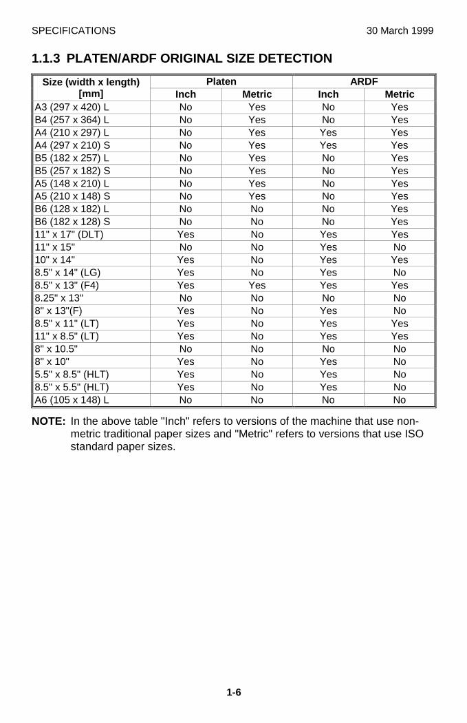
1.1.3 PLATEN/ARDF ORIGINAL SIZE DETECTION
Platen ARDFSize (width x length)[mm] Inch Metric Inch Metric
A3 (297 x 420) L No Yes No YesB4 (257 x 364) L No Yes No YesA4 (210 x 297) L No Yes Yes YesA4 (297 x 210) S No Yes Yes YesB5 (182 x 257) L No Yes No YesB5 (257 x 182) S No Yes No YesA5 (148 x 210) L No Yes No YesA5 (210 x 148) S No Yes No YesB6 (128 x 182) L No No No YesB6 (182 x 128) S No No No Yes11" x 17" (DLT) Yes No Yes Yes11" x 15" No No Yes No10" x 14" Yes No Yes Yes8.5" x 14" (LG) Yes No Yes No8.5" x 13" (F4) Yes Yes Yes Yes8.25" x 13" No No No No8" x 13"(F) Yes No Yes No8.5" x 11" (LT) Yes No Yes Yes11" x 8.5" (LT) Yes No Yes Yes8" x 10.5" No No No No8" x 10" Yes No Yes No5.5" x 8.5" (HLT) Yes No Yes No8.5" x 5.5" (HLT) Yes No Yes NoA6 (105 x 148) L No No No No
NOTE: In the above table "Inch" refers to versions of the machine that use non-metric traditional paper sizes and "Metric" refers to versions that use ISOstandard paper sizes.
30 March 1999 SPECIFICATIONS
1-7
Ove
rall
Info
rmat
ion
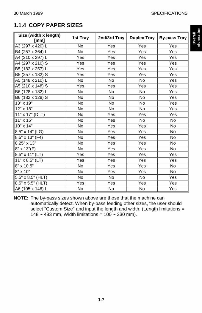
1.1.4 COPY PAPER SIZES
Size (width x length)[mm] 1st Tray 2nd/3rd Tray Duplex Tray By-pass Tray
A3 (297 x 420) L No Yes Yes YesB4 (257 x 364) L No Yes Yes YesA4 (210 x 297) L Yes Yes Yes YesA4 (297 x 210) S Yes Yes Yes YesB5 (182 x 257) L Yes Yes Yes YesB5 (257 x 182) S Yes Yes Yes YesA5 (148 x 210) L No No No YesA5 (210 x 148) S Yes Yes Yes YesB6 (128 x 182) L No No No YesB6 (182 x 128) S No No No Yes13" x 19" No No No Yes12" x 18" No No No Yes11" x 17" (DLT) No Yes Yes Yes11" x 15" No Yes No No10" x 14" No Yes Yes No8.5" x 14" (LG) No Yes Yes No8.5" x 13" (F4) No Yes Yes No8.25" x 13" No Yes Yes No8" x 13"(F) No Yes Yes No8.5" x 11" (LT) Yes Yes Yes Yes11" x 8.5" (LT) Yes Yes Yes Yes8" x 10.5" No Yes Yes No8" x 10" No Yes Yes No5.5" x 8.5" (HLT) No No No Yes8.5" x 5.5" (HLT) Yes Yes Yes YesA6 (105 x 148) L No No No Yes
NOTE: The by-pass sizes shown above are those that the machine canautomatically detect. When by-pass feeding other sizes, the user shouldselect "Custom Size" and input the length and width. (Length limitations =148 ~ 483 mm, Width limitations = 100 ~ 330 mm).
SPECIFICATIONS 30 March 1999
1-8
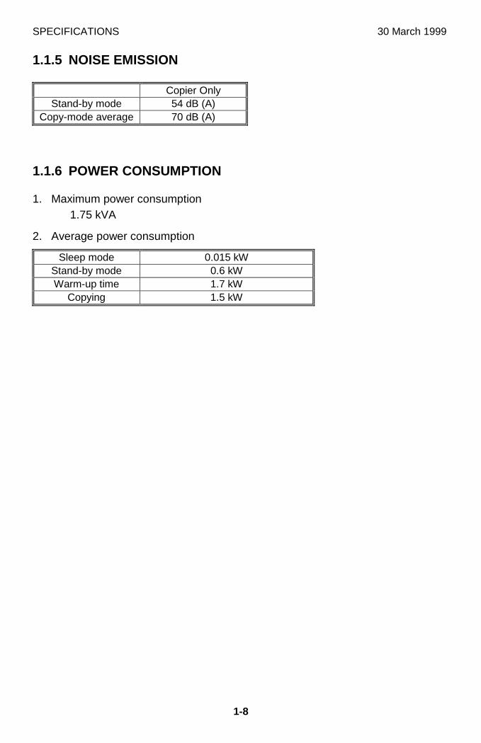
1.1.5 NOISE EMISSION
Copier OnlyStand-by mode 54 dB (A)
Copy-mode average 70 dB (A)
1.1.6 POWER CONSUMPTION
1. Maximum power consumption1.75 kVA
2. Average power consumption
Sleep mode 0.015 kWStand-by mode 0.6 kWWarm-up time 1.7 kW
Copying 1.5 kW
30 March 1999 MECHANISM OVERVIEW
1-9
Ove
rall
Info
rmat
ion
1.2 MECHANISM OVERVIEW
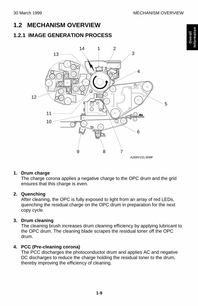
1.2.1 IMAGE GENERATION PROCESS
1. Drum chargeThe charge corona applies a negative charge to the OPC drum and the gridensures that this charge is even.
2. QuenchingAfter cleaning, the OPC is fully exposed to light from an array of red LEDs,quenching the residual charge on the OPC drum in preparation for the nextcopy cycle.
3. Drum cleaningThe cleaning brush increases drum cleaning efficiency by applying lubricant tothe OPC drum. The cleaning blade scrapes the residual toner off the OPCdrum.
4. PCC (Pre-cleaning corona)The PCC discharges the photoconductor drum and applies AC and negativeDC discharges to reduce the charge holding the residual toner to the drum,thereby improving the efficiency of cleaning.
A269V101.WMF
7
4
5
6
8
1 23
1413
12
11
10
9
MECHANISM OVERVIEW 30 March 1999
1-10
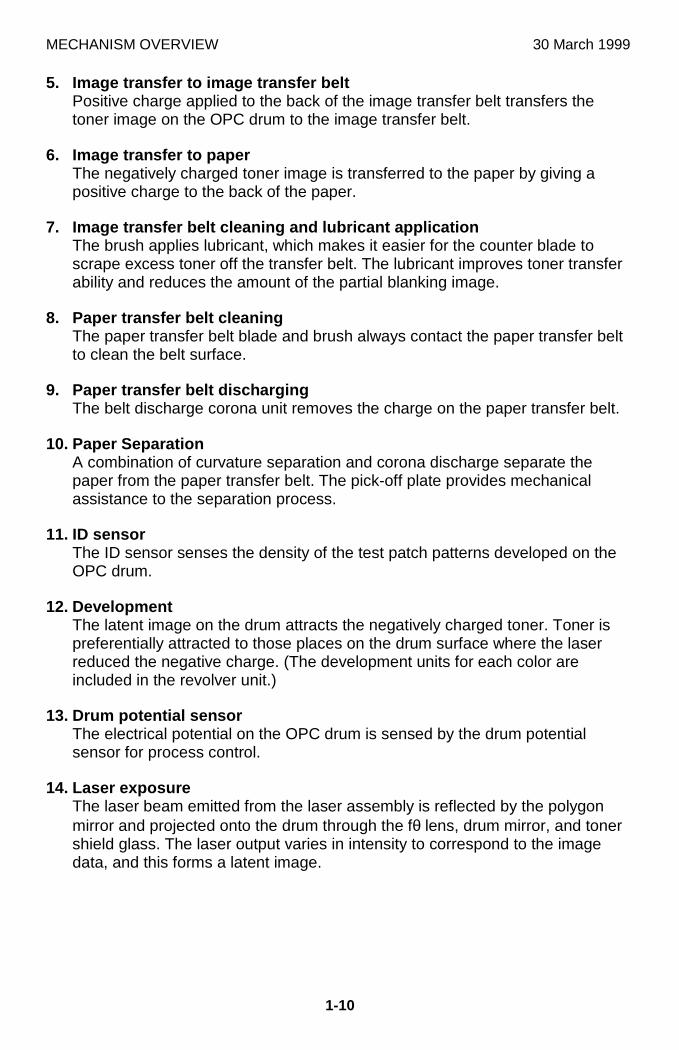
5. Image transfer to image transfer beltPositive charge applied to the back of the image transfer belt transfers thetoner image on the OPC drum to the image transfer belt.
6. Image transfer to paperThe negatively charged toner image is transferred to the paper by giving apositive charge to the back of the paper.
7. Image transfer belt cleaning and lubricant applicationThe brush applies lubricant, which makes it easier for the counter blade toscrape excess toner off the transfer belt. The lubricant improves toner transferability and reduces the amount of the partial blanking image.
8. Paper transfer belt cleaningThe paper transfer belt blade and brush always contact the paper transfer beltto clean the belt surface.
9. Paper transfer belt dischargingThe belt discharge corona unit removes the charge on the paper transfer belt.
10. Paper SeparationA combination of curvature separation and corona discharge separate thepaper from the paper transfer belt. The pick-off plate provides mechanicalassistance to the separation process.
11. ID sensorThe ID sensor senses the density of the test patch patterns developed on theOPC drum.
12. DevelopmentThe latent image on the drum attracts the negatively charged toner. Toner ispreferentially attracted to those places on the drum surface where the laserreduced the negative charge. (The development units for each color areincluded in the revolver unit.)
13. Drum potential sensorThe electrical potential on the OPC drum is sensed by the drum potentialsensor for process control.
14. Laser exposureThe laser beam emitted from the laser assembly is reflected by the polygonmirror and projected onto the drum through the fθ lens, drum mirror, and tonershield glass. The laser output varies in intensity to correspond to the imagedata, and this forms a latent image.
30 March 1999 MECHANISM OVERVIEW
1-11
Ove
rall
Info
rmat
ion
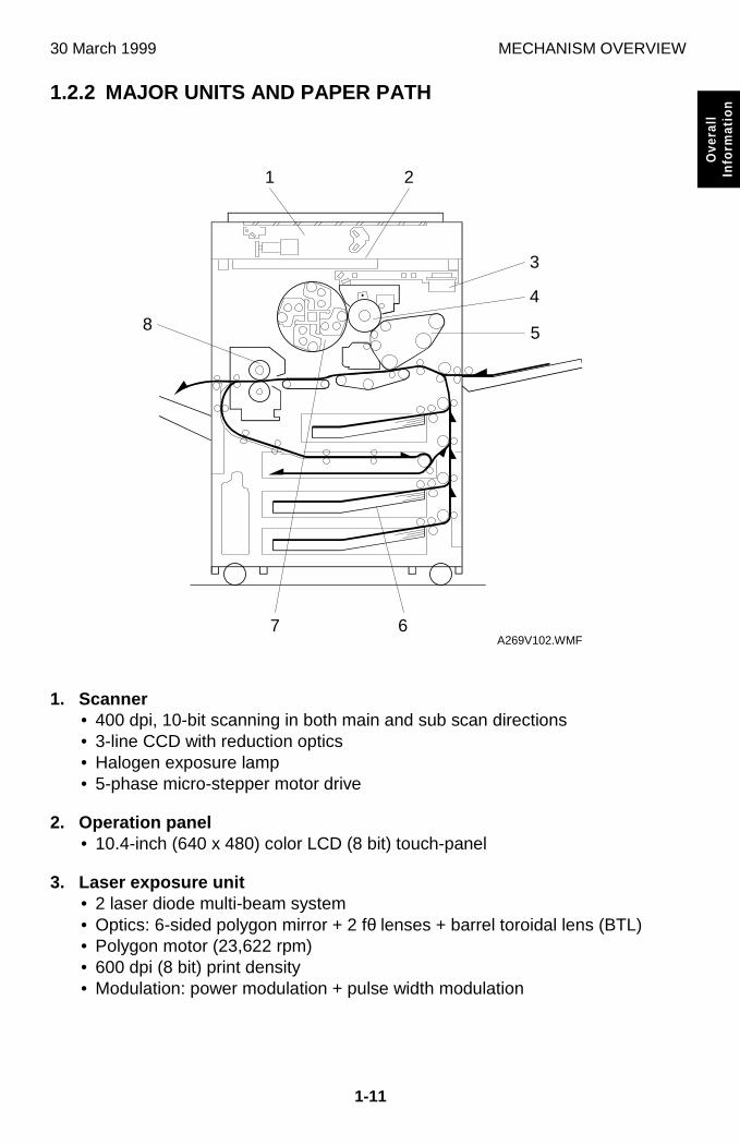
1.2.2 MAJOR UNITS AND PAPER PATH
1. Scanner• 400 dpi, 10-bit scanning in both main and sub scan directions• 3-line CCD with reduction optics• Halogen exposure lamp• 5-phase micro-stepper motor drive
2. Operation panel• 10.4-inch (640 x 480) color LCD (8 bit) touch-panel
3. Laser exposure unit• 2 laser diode multi-beam system• Optics: 6-sided polygon mirror + 2 fθ lenses + barrel toroidal lens (BTL)• Polygon motor (23,622 rpm)• 600 dpi (8 bit) print density• Modulation: power modulation + pulse width modulation
A269V102.WMF
3
21
4
58
7 6
MECHANISM OVERVIEW 30 July, 1999 (Revised)
1-12
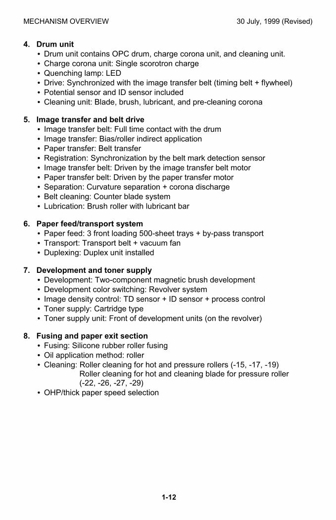
4. Drum unit• Drum unit contains OPC drum, charge corona unit, and cleaning unit.• Charge corona unit: Single scorotron charge• Quenching lamp: LED• Drive: Synchronized with the image transfer belt (timing belt + flywheel)• Potential sensor and ID sensor included• Cleaning unit: Blade, brush, lubricant, and pre-cleaning corona
5. Image transfer and belt drive• Image transfer belt: Full time contact with the drum• Image transfer: Bias/roller indirect application• Paper transfer: Belt transfer• Registration: Synchronization by the belt mark detection sensor• Image transfer belt: Driven by the image transfer belt motor• Paper transfer belt: Driven by the paper transfer motor• Separation: Curvature separation + corona discharge• Belt cleaning: Counter blade system• Lubrication: Brush roller with lubricant bar
6. Paper feed/transport system• Paper feed: 3 front loading 500-sheet trays + by-pass transport• Transport: Transport belt + vacuum fan• Duplexing: Duplex unit installed
7. Development and toner supply• Development: Two-component magnetic brush development• Development color switching: Revolver system• Image density control: TD sensor + ID sensor + process control• Toner supply: Cartridge type• Toner supply unit: Front of development units (on the revolver)
8. Fusing and paper exit section• Fusing: Silicone rubber roller fusing• Oil application method: roller• Cleaning: Roller cleaning for hot and pressure rollers (-15, -17, -19)
Roller cleaning for hot and cleaning blade for pressure roller(-22, -26, -27, -29)
• OHP/thick paper speed selection
30 March 1999 PARTS LAYOUT
1-13
Ove
rall
Info
rmat
ion
1.3 PARTS LAYOUT
1.3.1 MAJOR UNIT LAYOUT DIAGRAM
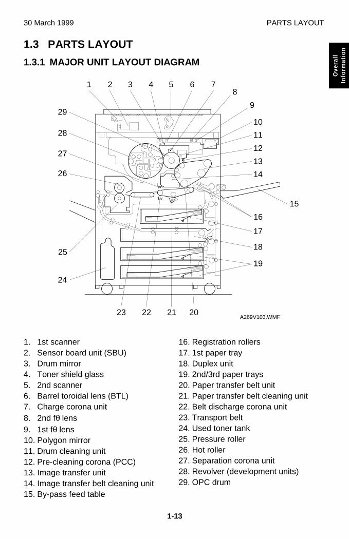
1. 1st scanner2. Sensor board unit (SBU)3. Drum mirror4. Toner shield glass5. 2nd scanner6. Barrel toroidal lens (BTL)7. Charge corona unit8. 2nd fθ lens9. 1st fθ lens10. Polygon mirror11. Drum cleaning unit12. Pre-cleaning corona (PCC)13. Image transfer unit14. Image transfer belt cleaning unit15. By-pass feed table
16. Registration rollers17. 1st paper tray18. Duplex unit19. 2nd/3rd paper trays20. Paper transfer belt unit21. Paper transfer belt cleaning unit22. Belt discharge corona unit23. Transport belt24. Used toner tank25. Pressure roller26. Hot roller27. Separation corona unit28. Revolver (development units)29. OPC drum
A269V103.WMF
5
10
6 7
11
12
13
14
8
9
16
15
17
18
19
21 202223
24
25
26
27
28
29
4321
DRIVE LAYOUT 30 July, 1999 (Revised)
1-14
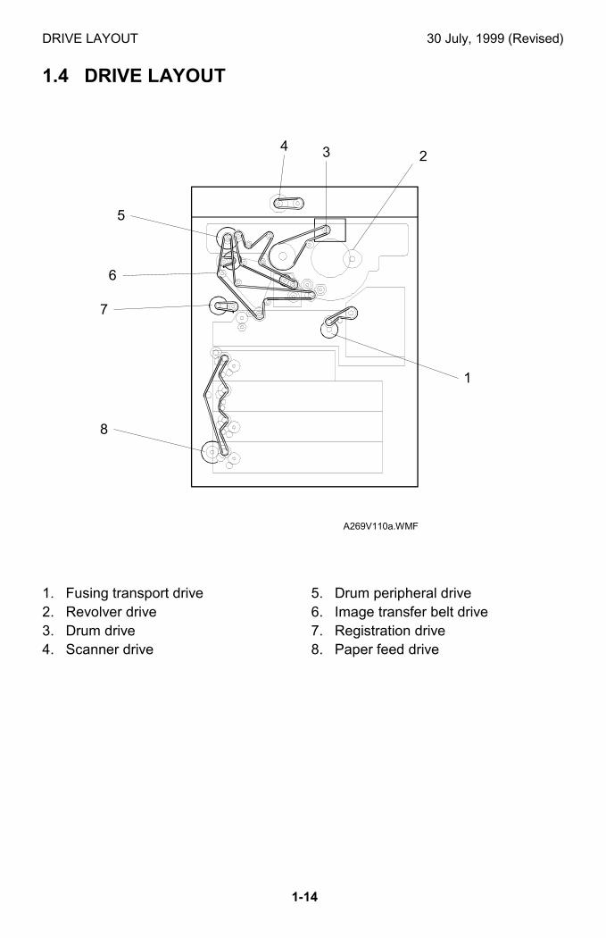
1.4 DRIVE LAYOUT
1. Fusing transport drive2. Revolver drive3. Drum drive4. Scanner drive
5. Drum peripheral drive6. Image transfer belt drive7. Registration drive8. Paper feed drive
A269V110a.WMF
3
8
24
7
5
1
6
30 March 1999 AIR FLOW
1-15
Ove
rall
Info
rmat
ion
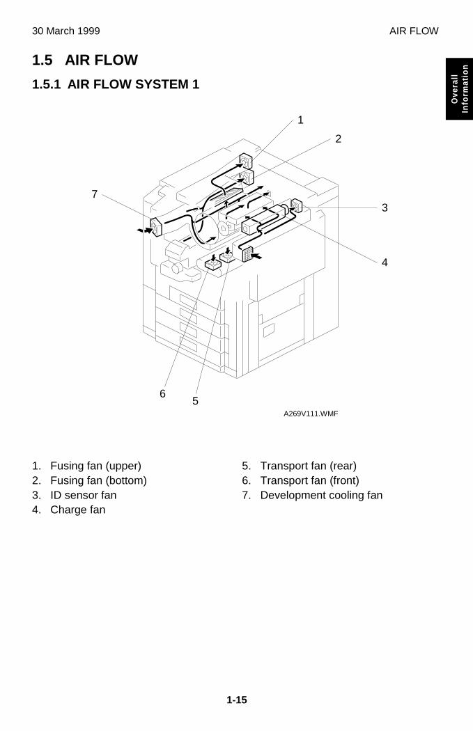
1.5 AIR FLOW
1.5.1 AIR FLOW SYSTEM 1
1. Fusing fan (upper)2. Fusing fan (bottom)3. ID sensor fan4. Charge fan
5. Transport fan (rear)6. Transport fan (front)7. Development cooling fan
A269V111.WMF
5
1
2
3
4
7
6
AIR FLOW 30 March 1999
1-16
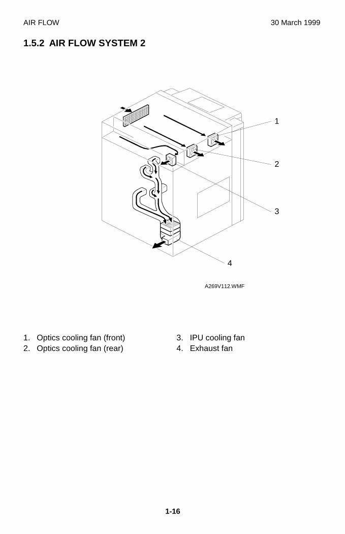
1.5.2 AIR FLOW SYSTEM 2
1. Optics cooling fan (front)2. Optics cooling fan (rear)
3. IPU cooling fan4. Exhaust fan
A269V112.WMF
4
3
2
1
30 March 1999 ELECTRICAL PARTS LAYOUT
1-17
Ove
rall
Info
rmat
ion
1.6 ELECTRICAL PARTS LAYOUT
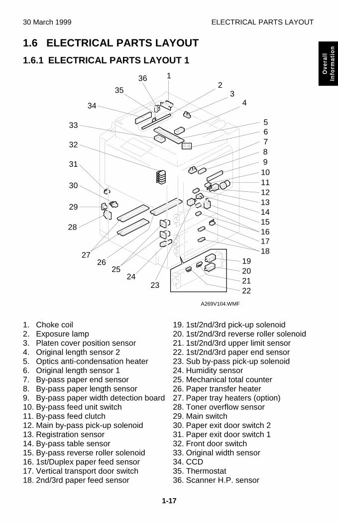
1.6.1 ELECTRICAL PARTS LAYOUT 1
1. Choke coil2. Exposure lamp3. Platen cover position sensor4. Original length sensor 25. Optics anti-condensation heater6. Original length sensor 17. By-pass paper end sensor8. By-pass paper length sensor9. By-pass paper width detection board10. By-pass feed unit switch11. By-pass feed clutch12. Main by-pass pick-up solenoid13. Registration sensor14. By-pass table sensor15. By-pass reverse roller solenoid16. 1st/Duplex paper feed sensor17. Vertical transport door switch18. 2nd/3rd paper feed sensor
19. 1st/2nd/3rd pick-up solenoid20. 1st/2nd/3rd reverse roller solenoid21. 1st/2nd/3rd upper limit sensor22. 1st/2nd/3rd paper end sensor23. Sub by-pass pick-up solenoid24. Humidity sensor25. Mechanical total counter26. Paper transfer heater27. Paper tray heaters (option)28. Toner overflow sensor29. Main switch30. Paper exit door switch 231. Paper exit door switch 132. Front door switch33. Original width sensor34. CCD35. Thermostat36. Scanner H.P. sensor
A269V104.WMF
14
1213
11
15
1716
1819
1098765
202122
4
2425
2627
28
29
30
31
32
33
32
34
35
36 1
23
ELECTRICAL PARTS LAYOUT 30 March 1999
1-18
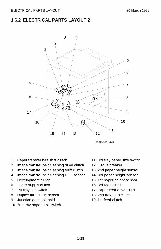
1.6.2 ELECTRICAL PARTS LAYOUT 2
1. Paper transfer belt shift clutch2. Image transfer belt cleaning drive clutch3. Image transfer belt cleaning shift clutch4. Image transfer belt cleaning H.P. sensor5. Development clutch6. Toner supply clutch7. 1st tray set switch8. Duplex turn guide sensor9. Junction gate solenoid10. 2nd tray paper size switch
11. 3rd tray paper size switch12. Circuit breaker13. 2nd paper height sensor14. 3rd paper height sensor15. 1st paper height sensor16. 3rd feed clutch17. Paper feed drive clutch18. 2nd tray feed clutch19. 1st feed clutch
A269V105.WMF
1
6
12
17
5
2
3 4
14 1315
16
18
19 7
8
9
10
11
30 March 1999 ELECTRICAL PARTS LAYOUT
1-19
Ove
rall
Info
rmat
ion
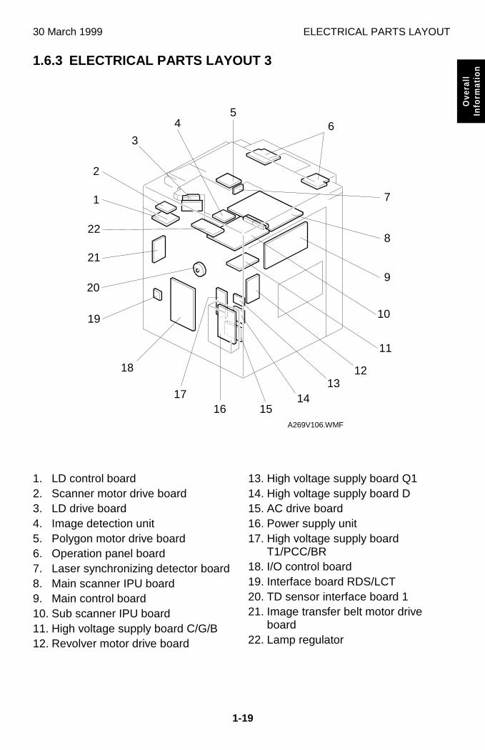
1.6.3 ELECTRICAL PARTS LAYOUT 3
1. LD control board2. Scanner motor drive board3. LD drive board4. Image detection unit5. Polygon motor drive board6. Operation panel board7. Laser synchronizing detector board8. Main scanner IPU board9. Main control board10. Sub scanner IPU board11. High voltage supply board C/G/B12. Revolver motor drive board
13. High voltage supply board Q114. High voltage supply board D15. AC drive board16. Power supply unit17. High voltage supply board
T1/PCC/BR18. I/O control board19. Interface board RDS/LCT20. TD sensor interface board 121. Image transfer belt motor drive
board22. Lamp regulator
A269V106.WMF
5
9
10
15
12
16
20
17
18
19
11
21
22
1
2
4
3
8
7
6
1314
ELECTRICAL PARTS LAYOUT 30 March 1999
1-20
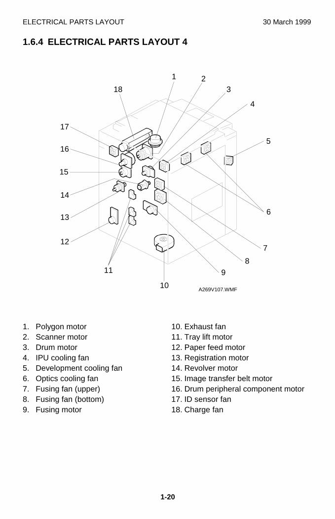
1.6.4 ELECTRICAL PARTS LAYOUT 4
1. Polygon motor2. Scanner motor3. Drum motor4. IPU cooling fan5. Development cooling fan6. Optics cooling fan7. Fusing fan (upper)8. Fusing fan (bottom)9. Fusing motor
10. Exhaust fan11. Tray lift motor12. Paper feed motor13. Registration motor14. Revolver motor15. Image transfer belt motor16. Drum peripheral component motor17. ID sensor fan18. Charge fan
A269V107.WMF
1 23
4
5
6
7
8
10
11
13
9
12
15
16
17
18
14
30 March 1999 ELECTRICAL PARTS LAYOUT
1-21
Ove
rall
Info
rmat
ion
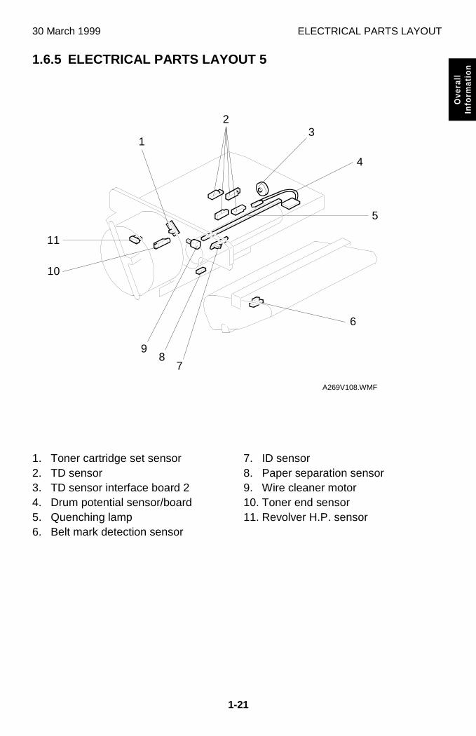
1.6.5 ELECTRICAL PARTS LAYOUT 5
1. Toner cartridge set sensor2. TD sensor3. TD sensor interface board 24. Drum potential sensor/board5. Quenching lamp6. Belt mark detection sensor
7. ID sensor8. Paper separation sensor9. Wire cleaner motor10. Toner end sensor11. Revolver H.P. sensor
A269V108.WMF
2
6
78
9
11
10
1
5
3
4
ELECTRICAL PARTS LAYOUT 30 March 1999
1-22
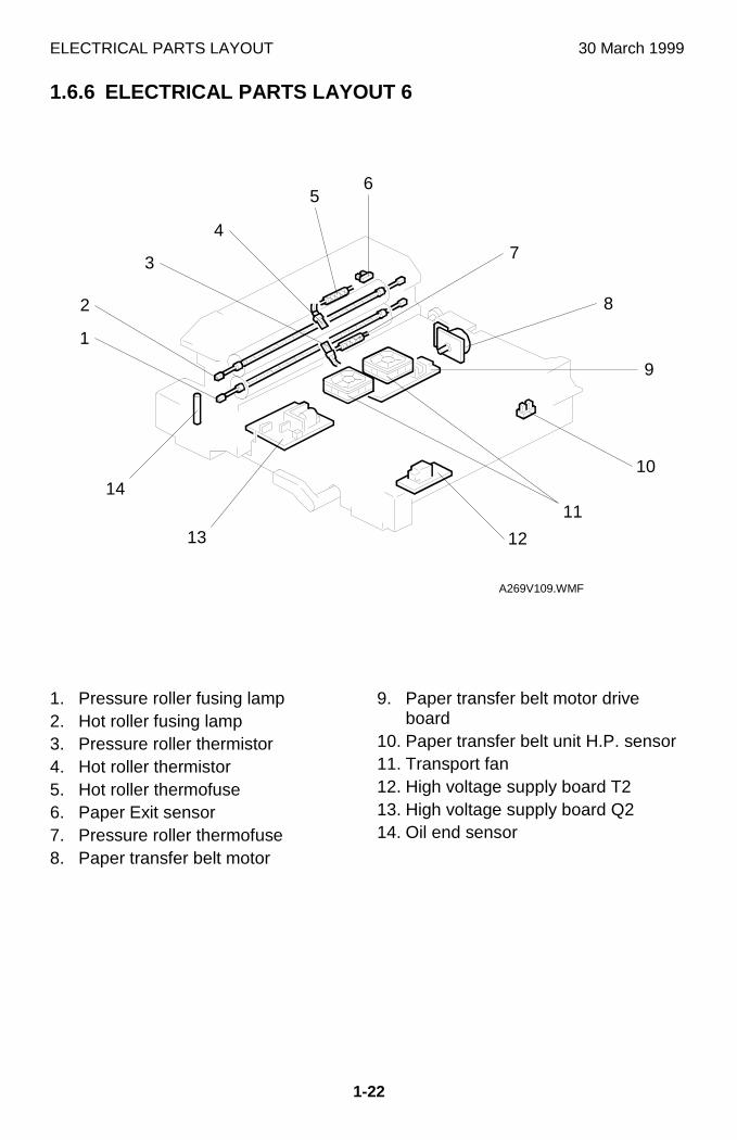
1.6.6 ELECTRICAL PARTS LAYOUT 6
1. Pressure roller fusing lamp2. Hot roller fusing lamp3. Pressure roller thermistor4. Hot roller thermistor5. Hot roller thermofuse6. Paper Exit sensor7. Pressure roller thermofuse8. Paper transfer belt motor
9. Paper transfer belt motor driveboard
10. Paper transfer belt unit H.P. sensor11. Transport fan12. High voltage supply board T213. High voltage supply board Q214. Oil end sensor
A269V109.WMF
65
7
8
9
10
11
1213
1
2
3
4
14
30 March 1999 ELECTRICAL PARTS LAYOUT
1-23
Ove
rall
Info
rmat
ion
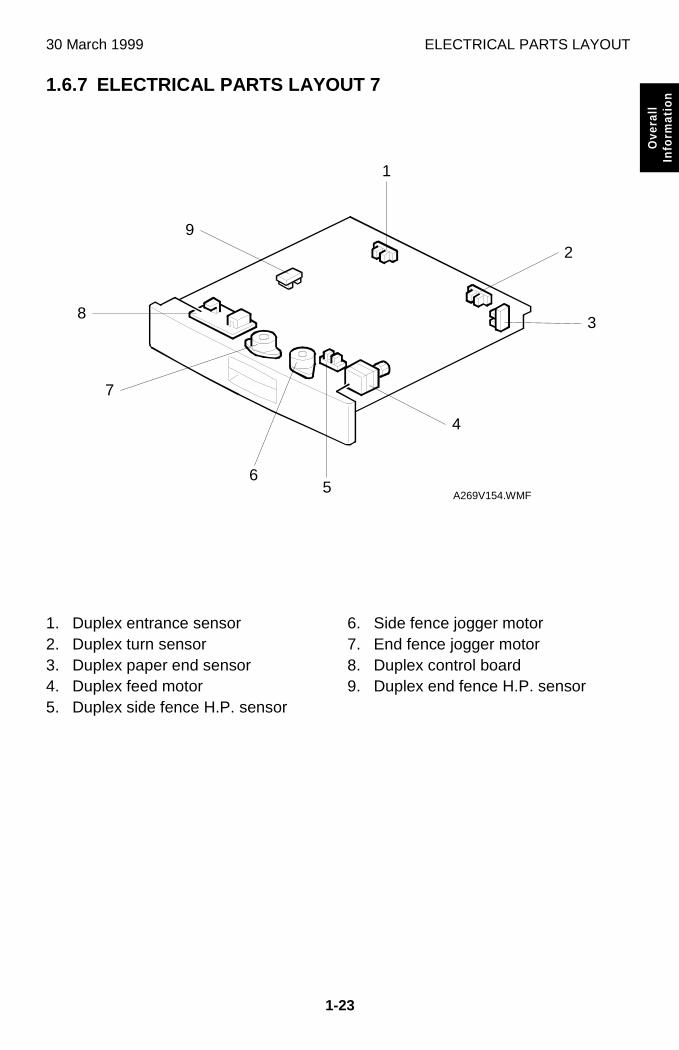
1.6.7 ELECTRICAL PARTS LAYOUT 7
1. Duplex entrance sensor2. Duplex turn sensor3. Duplex paper end sensor4. Duplex feed motor5. Duplex side fence H.P. sensor
6. Side fence jogger motor7. End fence jogger motor8. Duplex control board9. Duplex end fence H.P. sensor
A269V154.WMF
1
3
4
9
8
7
56
2
ELECTRICAL PARTS DESCRIPTIONS 30 March 1999
1-24
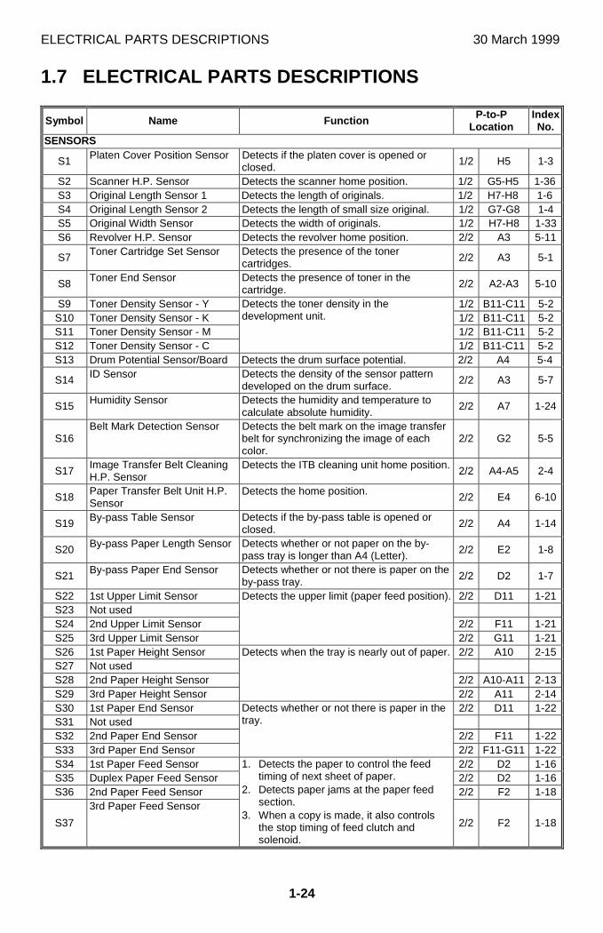
1.7 ELECTRICAL PARTS DESCRIPTIONS
Symbol Name Function P-to-PLocation
IndexNo.
SENSORS
S1 Platen Cover Position Sensor Detects if the platen cover is opened orclosed. 1/2 H5 1-3
S2 Scanner H.P. Sensor Detects the scanner home position. 1/2 G5-H5 1-36S3 Original Length Sensor 1 Detects the length of originals. 1/2 H7-H8 1-6S4 Original Length Sensor 2 Detects the length of small size original. 1/2 G7-G8 1-4S5 Original Width Sensor Detects the width of originals. 1/2 H7-H8 1-33S6 Revolver H.P. Sensor Detects the revolver home position. 2/2 A3 5-11
S7 Toner Cartridge Set Sensor Detects the presence of the tonercartridges. 2/2 A3 5-1
S8 Toner End Sensor Detects the presence of toner in thecartridge. 2/2 A2-A3 5-10
S9 Toner Density Sensor - Y 1/2 B11-C11 5-2S10 Toner Density Sensor - K 1/2 B11-C11 5-2S11 Toner Density Sensor - M 1/2 B11-C11 5-2S12 Toner Density Sensor - C
Detects the toner density in thedevelopment unit.
1/2 B11-C11 5-2S13 Drum Potential Sensor/Board Detects the drum surface potential. 2/2 A4 5-4
S14 ID Sensor Detects the density of the sensor patterndeveloped on the drum surface. 2/2 A3 5-7
S15 Humidity Sensor Detects the humidity and temperature tocalculate absolute humidity.
2/2 A7 1-24
S16Belt Mark Detection Sensor Detects the belt mark on the image transfer
belt for synchronizing the image of eachcolor.
2/2 G2 5-5
S17Image Transfer Belt CleaningH.P. Sensor
Detects the ITB cleaning unit home position. 2/2 A4-A5 2-4
S18Paper Transfer Belt Unit H.P.Sensor
Detects the home position. 2/2 E4 6-10
S19 By-pass Table Sensor Detects if the by-pass table is opened orclosed. 2/2 A4 1-14
S20 By-pass Paper Length Sensor Detects whether or not paper on the by-pass tray is longer than A4 (Letter). 2/2 E2 1-8
S21 By-pass Paper End Sensor Detects whether or not there is paper on theby-pass tray. 2/2 D2 1-7
S22 1st Upper Limit Sensor 2/2 D11 1-21S23 Not usedS24 2nd Upper Limit Sensor 2/2 F11 1-21S25 3rd Upper Limit Sensor
Detects the upper limit (paper feed position).
2/2 G11 1-21S26 1st Paper Height Sensor 2/2 A10 2-15S27 Not usedS28 2nd Paper Height Sensor 2/2 A10-A11 2-13S29 3rd Paper Height Sensor
Detects when the tray is nearly out of paper.
2/2 A11 2-14S30 1st Paper End Sensor 2/2 D11 1-22S31 Not usedS32 2nd Paper End Sensor 2/2 F11 1-22S33 3rd Paper End Sensor
Detects whether or not there is paper in thetray.
2/2 F11-G11 1-22S34 1st Paper Feed Sensor 2/2 D2 1-16S35 Duplex Paper Feed Sensor 2/2 D2 1-16S36 2nd Paper Feed Sensor 2/2 F2 1-18
S37
3rd Paper Feed Sensor
1. Detects the paper to control the feedtiming of next sheet of paper.
2. Detects paper jams at the paper feedsection.
3. When a copy is made, it also controlsthe stop timing of feed clutch andsolenoid.
2/2 F2 1-18
30 March 1999 ELECTRICAL PARTS DESCRIPTIONS
1-25
Ove
rall
Info
rmat
ion
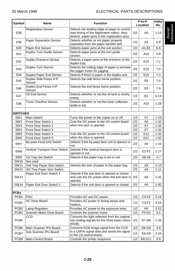
Symbol Name Function P-to-PLocation
IndexNo.
S38Registration Sensor Detects the leading edge of paper to control
start timing of the registration rollers. Also,detects paper jams in the registration area.
2/2 A5 1-13
S39 Paper Separation Sensor Detects whether or not paper properlyseparates from the paper transfer belt. 2/2 A3 5-8
S40 Paper Exit Sensor Detects paper jams at the exit section. 1/2 A1-B1 6-6
S41 Duplex Turn Guide Sensor Detects paper jams at the turn guidesection. 2/2 A10 2-8
S42 Duplex Entrance Sensor Detects a paper jams at the entrance of theduplex tray. 2/2 E10 7-1
S43 Duplex Turn Sensor Detects the trailing edge of paper to activatethe jogger motor for jogging.
2/2 E10 7-2
S44 Duplex Paper End Sensor Detects if there is paper in the duplex unit. 2/2 E10 7-3
S45 Duplex Side Fence H.P.Sensor
Detects the side fence home position. 2/2 E9 7-5
S46 Duplex End Fence H.P.Sensor
Detects the end fence home position. 2/2 E9 7-9
S47 Oil End Sensor Detects whether or not the oil tank is nearlyempty. 1/2 B1 6-14
S48 Toner Overflow Sensor Detects whether or not the toner collectionbottle is full. 2/2 A10 1-28
SWITCHESSW1 Main Switch Turns the power to the copier on or off. 1/2 F1 1-29SW2 Front Door Switch 1 2/2 A6 1-32SW3 Front Door Switch 2 2/2 A7 1-32SW4 Front Door Switch 3
Cuts the DC power to the I/O control boardwhen the door is opened.
2/2 A7 1-32SW5 Front Door Switch 4 1/2 G11 1-32SW6 Front Door Switch 5
Cuts the DC power to the LD control boardwhen the door is opened. 1/2 G11 1-32
SW7 By-pass Feed Unit Switch Detects if the by-pass feed unit is opened ornot. 2/2 A6 1-10
SW8 Vertical Transport Door Switch Detects if the vertical transport door isopened or not. 2/2 E2-F2 1-17
SW9 1st Tray Set Switch 2/2 A8-A9 2-7SW10 Not used
Detects if the paper tray is set or not.
SW11 2nd Tray Paper Size Switch 2/2 A9 2-10SW12 3rd Tray Paper Size Switch
Detects the size of paper in the paper tray.2/2 A9 2-11
SW13Paper Exit Door Switch 1 Detects if the exit door is opened or closed
and cuts the DC power when the exit door isopened.
2/2 A6 1-31
SW14 Paper Exit Door Switch 2 Detects if the exit door is opened or closed. 2/2 A6 1-30
PCBsPCB1 PSU Provides AC and DC power. 1/2 C3-F2 3-16
PCB2 AC Drive Board Provides AC power to fusing lamps andheaters. 1/2 C3-F2 3-15
PCB3 Lamp Regulator Provides AC power to the exposure lamp. 1/2 H5 3-22PCB4 Scanner Motor Drive Board Controls the scanner motor. 1/2 F5-G5 3-2
PCB5CCD Converts the light reflected from the original
into analog signals for the three basic colors(RGB).
1/2 D7-D8 1-34
PCB6 Main Scanner IPU Board 1/2 D6-G8 3-8
PCB7 Sub Scanner IPU BoardConverts RGB image signal from the CCDto a CMYK signal data and sends the signalto the LD control board. 1/2 E6-G9 3-10
PCB8 Main Control Board Controls the printer sequence. 1/2 B8-D11 3-9
ELECTRICAL PARTS DESCRIPTIONS 30 March 1999
1-26
Symbol Name Function P-to-PLocation
IndexNo.
PCB9I/O Control Board Interfaces the sensors, clutches, solenoids,
and motors in the printer module with themain control board.
1/22/2
A2-A11C11-H1 3-18
PCB10 LD Control Board Controls laser synchronization. 1/2 F9-F11 3-1PCB11 LD Drive Board Controls the LD output. 1/2 D10 3-3PCB12 Polygon Motor Drive Board Controls the polygon mirror motor. 1/2 G11 3-5
PCB13 Laser Synchronizing DetectorBoard
Detects the laser beam to control the starttiming of main scan writing. 1/2 G11 3-7
PCB14 IDU (Image Detection Unit) Analyzes images for anti-counterfeiting. 1/2 G8 3-4
PCB15High Voltage Supply BoardC/G/B
Provides power to the charge corona unitand development rollers. 2/2 B1-B2 3-11
PCB16 TD Sensor Interface Board 1 1/2 B11 3-20
PCB17 TD Sensor Interface Board 2Provides power to the TD sensors andtransmits the output data from the sensorsto the main control board. 1/2 B11 5-3
PCB18 Revolver Motor Drive Board Controls the revolver motor. 2/2 D3-E3 3-12
PCB19Image Transfer Belt MotorDrive Board
Controls the image transfer belt motor. 2/2 F1-G2 3-21
PCB20High Voltage Supply BoardT1/PCC/BR
Provides power to the image transfer beltbias roller, PCC unit, and drum cleaningbias roller.
2/2 B1 3-17
PCB21 Paper Transfer Belt MotorDrive Board
Controls the paper transfer belt motor. 2/2 D5-E5 6-9
PCB22 High Voltage Supply Board T2 Provides power to the paper transfer beltbias roller. 2/2 E4 6-12
PCB23 High Voltage Supply Board Q1 Provides power to the lubricant brush. 2/2 E6-E7 3-13
PCB24 High Voltage Supply Board Q2 Provides power to the paper transfer beltdischarge corona unit. 2/2 E4 6-13
PCB25 High Voltage Supply Board D Provides power to the paper separationcorona unit. 2/2 A9-A10 3-14
PCB26 Operation Panel Board Used to operate the copier. 1/2 C11-D11 3-6
PCB27Interface Board RDS/LCT Interfaces the sensors, clutches, solenoids,
and motors in the LCT with the main controlboard.
1/2 B6-C7 3-17
PCB28By-pass Paper WidthDetection Board
Detects the width of paper. 2/2 E2 1-9
PCB29 Duplex Control Board Controls the duplex unit. 2/2 D8-E10 7-9
MOTORSM1 Polygon Motor Drives the polygon mirror. 1/2 G11 4-1M2 Wire Cleaner Motor Drives the charge wire cleaner. 2/2 A4 5-9M3 Drum Motor Drives the drum. 2/2 D5-E6 4-3
M4Drum peripheral componentMotor
Drives the drum cleaning unit, toner supplyunit, development unit, and image transferbelt cleaning unit.
2/2 H2 4-16
M5 Image Transfer Belt Motor Drives the image transfer belt. 2/2 F2 4-15M6 Paper Transfer Belt Motor Drives the paper transfer belt. 2/2 E5 6-8M7 1st Tray Lift Motor 2/2 D10-D11 4-11M8 Not usedM9 2nd Tray Lift Motor 2/2 F10-F11 4-11
M10 3rd Tray Lift Motor
Lifts the tray bottom plate up.
2/2 G10-G11 4-11
M11 Paper Feed Motor Drives the paper feed mechanism for alltrays. 2/2 A8 4-12
M12 Fusing Motor Drives the paper transport belts and fusingrollers. 2/2 A11 4-9
STM1 Scanner Motor Drives the scanner. 1/2 G4 4-2STM2 Revolver Motor Drives the revolver unit. 2/2 E3 4-14STM3 Registration Motor Drives the registration roller. 2/2 A6 4-13
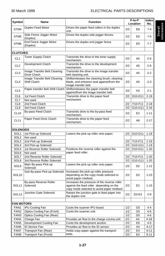
30 March 1999 ELECTRICAL PARTS DESCRIPTIONS
1-27
Ove
rall
Info
rmat
ion
Symbol Name Function P-to-PLocation
IndexNo.
STM4 Duplex Feed Motor Drives the paper feed rollers in the duplexunit. 2/2 E8 7-4
STM5Side Fence Jogger Motor(Duplex)
Drives the duplex side jogger fences. 2/2 E9 7-6
STM6End Fence Jogger Motor(Duplex)
Drives the duplex end jogger fence. 2/2 E9 7-7
CLUTCHES
CL1 Toner Supply Clutch Transmits the drive to the toner supplymechanism. 2/2 A5 2-6
CL2 Development Clutch Transmits the drive to the developmentmechanism. 2/2 A5 2-5
CL3 Image Transfer Belt CleaningDrive Clutch
Transmits the drive to the image transferbelt cleaning unit. 2/2 A5 2-2
CL4Image Transfer Belt CleaningShift Clutch
Shifts/releases the cleaning brush, cleaningblade, and entrance seal against/from theimage transfer belt.
2/2 A5 2-3
CL5 Paper transfer Belt Shift Clutch Shifts/releases the paper transfer beltagainst/from the image transfer belt. 2/2 H2 2-1
CL6 1st Feed Clutch 2/2 D10-D11 2-19CL7 Not usedCL8 2nd Feed Clutch 2/2 F10-F11 2-18CL9 3rd Feed Clutch
Transmits drive to the paper feedmechanism.
2/2 G10-G11 2-16
CL10 By-pass Feed Clutch Transmits drive to the by-pass feedmechanism. 2/2 E2 1-11
CL11 Paper Feed Drive Clutch Transmits drive to the paper feedmechanism. 2/2 A8 2-17
SOLENOIDSSOL1 1st Pick-up Solenoid 2/2 D10-D11 1-19SOL2 Not usedSOL3 2nd Pick-up Solenoid 2/2 F10-F11 1-19SOL4 3rd Pick-up Solenoid
Lowers the pick-up roller onto paper.
2/2 G10-G11 1-19SOL5 1st Reverse Roller Solenoid 2/2 D10-D11 1-20SOL6 Not usedSOL7 2nd Reverse Roller Solenoid 2/2 F10-F11 1-20SOL8 3rd Reverse Roller Solenoid
Positions the reverse roller against thepaper feed roller.
2/2 G10-G11 1-20
SOL9Main By-pass Pick-upSolenoid
Lowers the pick-up roller onto paper. 2/2 D2 1-12
SOL10Sub By-pass Pick-up Solenoid Increases the pick-up roller pressure
depending on the copy mode selected toavoid paper misfeed.
2/2 D2 1-23
SOL11By-pass Reverse RollerSolenoid
Increases the pressure of the reverse rolleragainst the feed roller depending on thecopy mode selected to avoid paper misfeed.
2/2 E2 1-15
SOL12 Junction Gate Solenoid Raises the junction gate to feed paper intothe duplex unit. 2/2 D3-E3 2-9
FAN MOTORSFAN1 IPU Cooling Fan Cools the scanner IPU board. 1/2 G5 4-4FAN2 Optics Cooling Fan (Front) 1/2 G5 4-6FAN3 Optics Cooling Fan (Rear)
Cools the scanner unit.1/2 G5 4-6
FAN4 Charge Fan Provides air flow to the charge corona unit. 2/2 A4 4-18FAN5 Development Cooling Fan Cools the development section. 2/2 E6 4-5FAN6 ID Sensor Fan Provides air flow to the ID sensor. 2/2 A4 4-17FAN7 Transport Fan (Rear) 2/2 E4 6-11FAN8 Transport Fan (Front)
Holds copy paper against the transportbelts. 2/2 E4 6-11
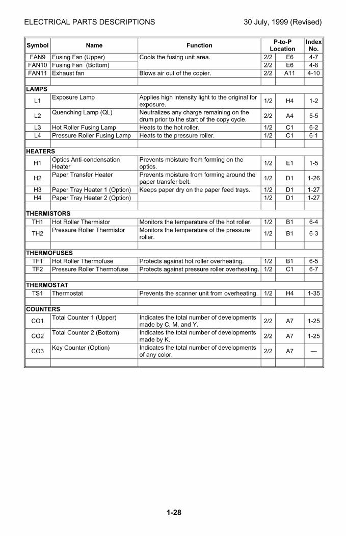
ELECTRICAL PARTS DESCRIPTIONS 30 July, 1999 (Revised)
1-28
Symbol Name FunctionP-to-PLocation
IndexNo.
FAN9 Fusing Fan (Upper) 2/2 E6 4-7FAN10 Fusing Fan (Bottom)
Cools the fusing unit area.2/2 E6 4-8
FAN11 Exhaust fan Blows air out of the copier. 2/2 A11 4-10
LAMPS
L1Exposure Lamp Applies high intensity light to the original for
exposure.1/2 H4 1-2
L2Quenching Lamp (QL) Neutralizes any charge remaining on the
drum prior to the start of the copy cycle.2/2 A4 5-5
L3 Hot Roller Fusing Lamp Heats to the hot roller. 1/2 C1 6-2L4 Pressure Roller Fusing Lamp Heats to the pressure roller. 1/2 C1 6-1
HEATERS
H1Optics Anti-condensationHeater
Prevents moisture from forming on theoptics.
1/2 E1 1-5
H2Paper Transfer Heater Prevents moisture from forming around the
paper transfer belt.1/2 D1 1-26
H3 Paper Tray Heater 1 (Option) 1/2 D1 1-27H4 Paper Tray Heater 2 (Option)
Keeps paper dry on the paper feed trays.1/2 D1 1-27
THERMISTORSTH1 Hot Roller Thermistor Monitors the temperature of the hot roller. 1/2 B1 6-4
TH2Pressure Roller Thermistor Monitors the temperature of the pressure
roller.1/2 B1 6-3
THERMOFUSESTF1 Hot Roller Thermofuse Protects against hot roller overheating. 1/2 B1 6-5TF2 Pressure Roller Thermofuse Protects against pressure roller overheating. 1/2 C1 6-7
THERMOSTATTS1 Thermostat Prevents the scanner unit from overheating. 1/2 H4 1-35
COUNTERS
CO1Total Counter 1 (Upper) Indicates the total number of developments
made by C, M, and Y.2/2 A7 1-25
CO2Total Counter 2 (Bottom) Indicates the total number of developments
made by K.2/2 A7 1-25
CO3Key Counter (Option) Indicates the total number of developments
of any color.2/2 A7 —
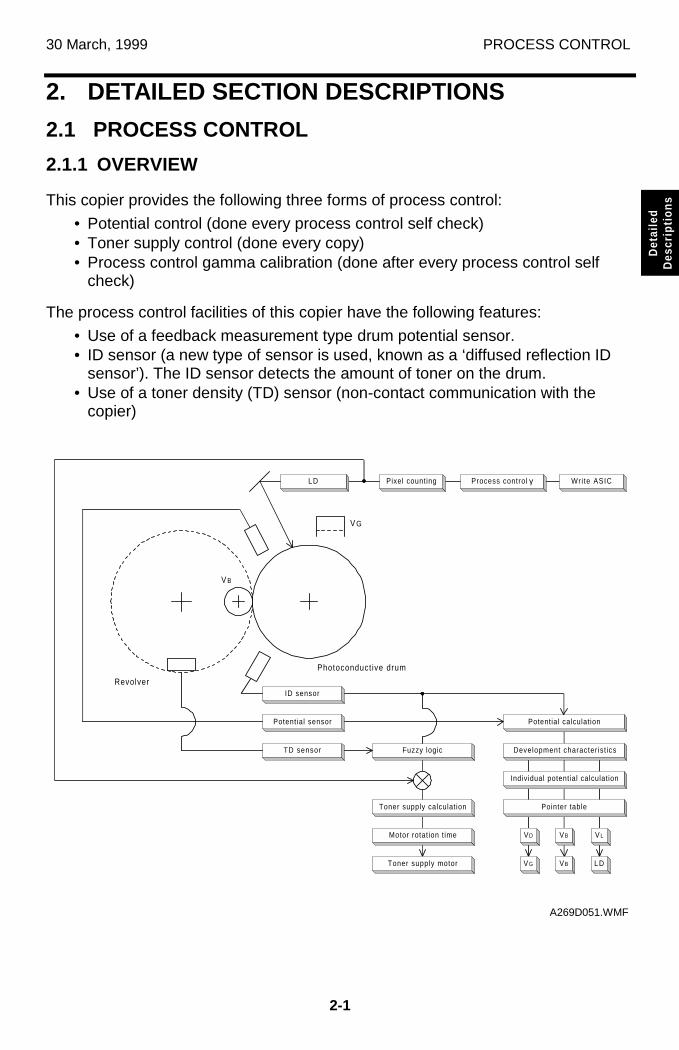
30 March, 1999 PROCESS CONTROL
2-1
Det
aile
dD
escr
iptio
ns
2. DETAILED SECTION DESCRIPTIONS
2.1 PROCESS CONTROL
2.1.1 OVERVIEW
This copier provides the following three forms of process control:
• Potential control (done every process control self check)• Toner supply control (done every copy)• Process control gamma calibration (done after every process control self
check)
The process control facilities of this copier have the following features:
• Use of a feedback measurement type drum potential sensor.• ID sensor (a new type of sensor is used, known as a ‘diffused reflection ID
sensor’). The ID sensor detects the amount of toner on the drum.• Use of a toner density (TD) sensor (non-contact communication with the
copier)
Potential sensor
Fuzzy logic
Potential calculation
Development characterist ics
Individual potential calculation
Pointer table
VD VB V L
V G VB L D
Toner supply calculation
Motor rotation t ime
Toner supply motor
ID sensor
L D Pixel counting Wri te ASIC
V G
V B
Revolver
TD sensor
Photoconduct ive drum
Process control γ
A269D051.WMF
PROCESS CONTROL 30 July, 1999 (Revised)
2-2
2.1.2 POTENTIAL CONTROL
Overview
Potential control is the process of controlling the development potential to maintainthe density of the toner image on the drum. It does this by compensating forvariations in drum chargeability and toner chargeability.
The machine uses the image density (ID) sensor to measure drum reflectivity andthe density of a standard sensor pattern. It uses the drum potential sensor to detectthe potential on the standard sensor pattern (before the pattern is developed).These tests are done during the process control self check, which is done atspecific times (such as after replacing the developer).
The ID and drum potential sensor outputs are used to calculate the developmentpotential. This is the difference between the development bias voltage and thevoltage of areas of the drum that have been discharged by laser exposure at fullpower. If changes in this potential are not accounted for, the color balance will bepoor.
Depending on the development potential that is calculated, the machine uses alook-up table in memory (called a pointer table) to adjust the following:
• VD: Drum potential without exposure - to adjust this, the machine adjusts thecharge corona grid voltage (VG)
• VL: Drum potential with the strongest exposure - to adjust this, the machineadjusts the laser diode input current (ILD)
• VB: Development bias
Potential control controls the development potential so that the maximum amountof toner applied to the drum is kept constant. However, the medium (greyscale)range is ignored. To improve this situation, a new process called ‘process controlgamma correction’ is done after potential control. This process defines LD outputfor all 256 grades of the greyscale (development bias and charge corona gridpotential are not affected).
Potential Control Timing
The machine carries out potential control using a procedure called the ‘processcontrol self check’. Process control gamma correction (covered in section 2.1.3) isthen done immediately after the process control self check. There are five types ofprocess control self check, categorized according to their execution times. Processcontrol takes approximately 3 minutes.
(1) Forced Process Control Self Check
After replacing the developer or drum, the technician must do the forced processcontrol procedure (SP3-126).
30 March, 1999 PROCESS CONTROL
2-3
Det
aile
dD
escr
iptio
ns
(2) Initial Process Control Self Check
The initial process control starts automatically when the power is turned on (orwhen the machine returns to standby mode from sleep mode), but only if the hotroller in the fusing unit is less than 100 degrees centigrade. This process control isdone only when SP3-125 (Set Potential Control Method) is set to "0 (Auto)."
(3) Interval Process Control Self Check
The copy interval process control starts automatically at the end of a copy jobduring which the total number of copies exceeds a preset value.
The preset value can be defined using SP3-973 (Set Process Control Self CheckInterval). The factory setting is 150 sheets. The maximum possible interval is 500sheets. Using a shorter interval reduces the machine’s average copying speed.Setting the process control interval to 0 disables the interval process control.
(4) Timed Process Control Self Check
This process control self check is activated at a predetermined time interval(hours). This check is identical to the interval process control self check. This selfcheck is initiated by entering a value (defaulting to 6 hours) in SP3-972-00. Thesettable range is 0 to 240. Entering a value of 0 suppresses the execution of thisself check.
The timer is reset by the following conditions:
• At the finish of any other process control self-check• At the finish of image processing (copying or printing)• When the main switch or the operation switch is turned OFF/ON.• When any door or cover is opened and closed.• At the end of toner end recovery.
NOTE: Just pressing operation panel keys does not reset the timer.
(5) ACC-Run-Time Process Control Self Check
A process control self check that is activated before the execution of ACC (autocolor calibration). This check is identical to the interval process control self check.
This process control self check is done when SP4-507 (ACC process controlON/OFF) is set to “3” (Both Copy/Printer ACC). If a value of 0 is entered, thisprocess control self check is not done.
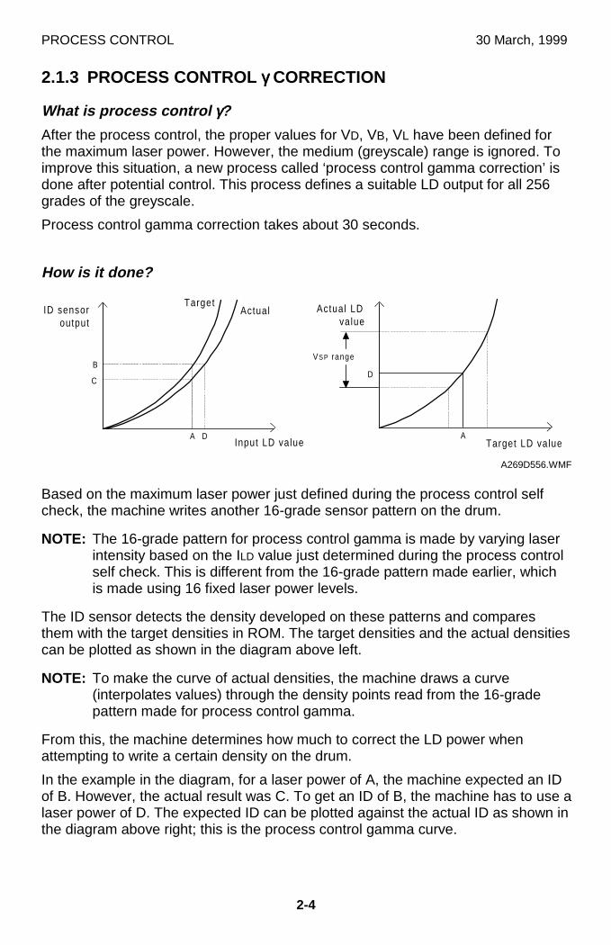
PROCESS CONTROL 30 March, 1999
2-4
2.1.3 PROCESS CONTROL γγγγ CORRECTION
What is process control γγγγ?
After the process control, the proper values for VD, VB, VL have been defined forthe maximum laser power. However, the medium (greyscale) range is ignored. Toimprove this situation, a new process called ‘process control gamma correction’ isdone after potential control. This process defines a suitable LD output for all 256grades of the greyscale.
Process control gamma correction takes about 30 seconds.
How is it done?
Based on the maximum laser power just defined during the process control selfcheck, the machine writes another 16-grade sensor pattern on the drum.
NOTE: The 16-grade pattern for process control gamma is made by varying laserintensity based on the ILD value just determined during the process controlself check. This is different from the 16-grade pattern made earlier, whichis made using 16 fixed laser power levels.
The ID sensor detects the density developed on these patterns and comparesthem with the target densities in ROM. The target densities and the actual densitiescan be plotted as shown in the diagram above left.
NOTE: To make the curve of actual densities, the machine draws a curve(interpolates values) through the density points read from the 16-gradepattern made for process control gamma.
From this, the machine determines how much to correct the LD power whenattempting to write a certain density on the drum.
In the example in the diagram, for a laser power of A, the machine expected an IDof B. However, the actual result was C. To get an ID of B, the machine has to use alaser power of D. The expected ID can be plotted against the actual ID as shown inthe diagram above right; this is the process control gamma curve.
DInput LD value
ID sensoroutput
TargetActual
B
A
C
Target LD value
Actual LDvalue
VS P range
A
D
A269D556.WMF
30 March, 1999 PROCESS CONTROL
2-5
Det
aile
dD
escr
iptio
ns
Process control γ target is stored in the NV-RAM on the main control board. TheCPU calculates the process control γ on the main board. The results of processcontrol γ calculation go to the LD main control board to compensate the LD inputdata.
The process control gamma obtained cannot be adjusted in SP mode.
Process Control γγγγ Correction Timing
The machine automatically does process control gamma correction at the end ofevery process control self check.
Relationship Between Process Control γγγγ Correction, ACC, and Other γγγγCorrections
Process control γ correction is executed so that the amount of toner attached to thedrum against the LD write value has the intended characteristic within the processrange between LD write and development section. However, the ACC correctionencompasses the process range from scanning to image generation (including thescope of process control γ correction).
Potential control and process control γ correction have different goals. The ultimatepurpose of potential control is to adjust the maximum amount of toner attached tothe drum against the development potential to a certain target value. Processcontrol γ correction, however, adjusts the amount of toner at all levels of the 16gradation patterns to the target characteristics and interpolates between the 16adjusted levels to make all 256 grayscale grades. This correction is used to makethe image characteristics in low ID sections closer to the target value.
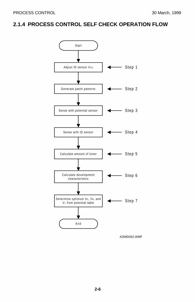
PROCESS CONTROL 30 March, 1999
2-6
2.1.4 PROCESS CONTROL SELF CHECK OPERATION FLOW
Determine opt imum VD, VB, andV L from potential table
Start
Adjust ID sensor VS G
Generate patch patterns
Sense with potential sensor
Sense with ID sensor
Calculate amount of toner
Calculate developmentcharacterist ics
End
Step 1
Step 2
Step 3
Step 4
Step 5
Step 6
Step 7
A269D052.WMF
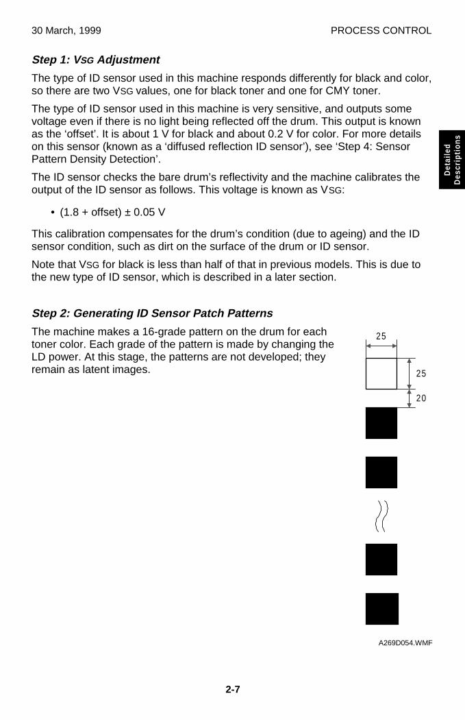
30 March, 1999 PROCESS CONTROL
2-7
Det
aile
dD
escr
iptio
ns
Step 1: V SG Adjustment
The type of ID sensor used in this machine responds differently for black and color,so there are two VSG values, one for black toner and one for CMY toner.
The type of ID sensor used in this machine is very sensitive, and outputs somevoltage even if there is no light being reflected off the drum. This output is knownas the ‘offset’. It is about 1 V for black and about 0.2 V for color. For more detailson this sensor (known as a ‘diffused reflection ID sensor’), see ‘Step 4: SensorPattern Density Detection’.
The ID sensor checks the bare drum’s reflectivity and the machine calibrates theoutput of the ID sensor as follows. This voltage is known as VSG:
• (1.8 + offset) ± 0.05 V
This calibration compensates for the drum’s condition (due to ageing) and the IDsensor condition, such as dirt on the surface of the drum or ID sensor.
Note that VSG for black is less than half of that in previous models. This is due tothe new type of ID sensor, which is described in a later section.
Step 2: Generating ID Sensor Patch Patterns
The machine makes a 16-grade pattern on the drum for eachtoner color. Each grade of the pattern is made by changing theLD power. At this stage, the patterns are not developed; theyremain as latent images.
���������������������������������������������������������������
������������������������������������������������������������������������������������
����������������������������������������������������������������������������������������
������������������������������������������������������������������������������������
25
25
20
A269D054.WMF
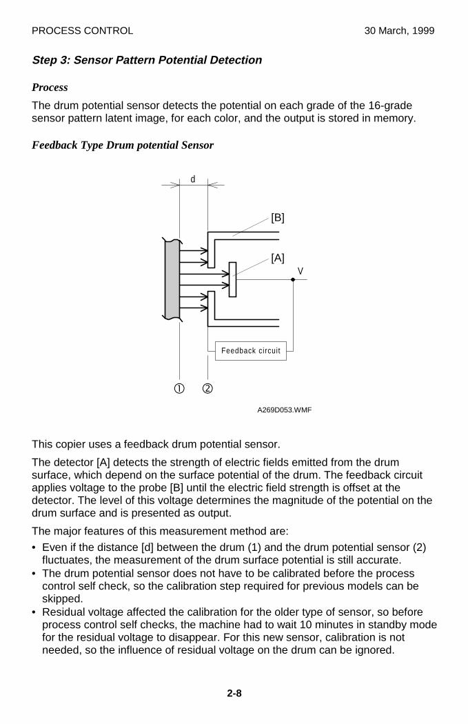
PROCESS CONTROL 30 March, 1999
2-8
Step 3: Sensor Pattern Potential Detection
Process
The drum potential sensor detects the potential on each grade of the 16-gradesensor pattern latent image, for each color, and the output is stored in memory.
Feedback Type Drum potential Sensor
This copier uses a feedback drum potential sensor.
The detector [A] detects the strength of electric fields emitted from the drumsurface, which depend on the surface potential of the drum. The feedback circuitapplies voltage to the probe [B] until the electric field strength is offset at thedetector. The level of this voltage determines the magnitude of the potential on thedrum surface and is presented as output.
The major features of this measurement method are:
• Even if the distance [d] between the drum (1) and the drum potential sensor (2)fluctuates, the measurement of the drum surface potential is still accurate.
• The drum potential sensor does not have to be calibrated before the processcontrol self check, so the calibration step required for previous models can beskipped.
• Residual voltage affected the calibration for the older type of sensor, so beforeprocess control self checks, the machine had to wait 10 minutes in standby modefor the residual voltage to disappear. For this new sensor, calibration is notneeded, so the influence of residual voltage on the drum can be ignored.
V
Feedback circuit
dc
d
A269D053.WMF
[A]
[B]
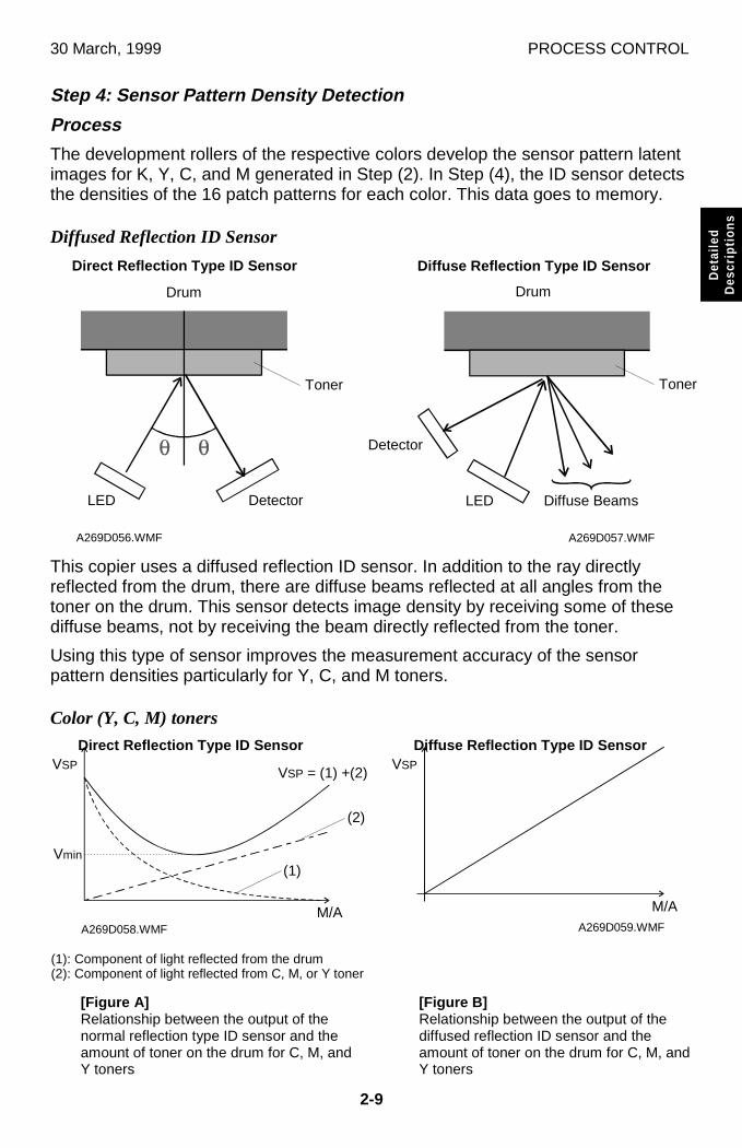
30 March, 1999 PROCESS CONTROL
2-9
Det
aile
dD
escr
iptio
ns
Step 4: Sensor Pattern Density Detection
Process
The development rollers of the respective colors develop the sensor pattern latentimages for K, Y, C, and M generated in Step (2). In Step (4), the ID sensor detectsthe densities of the 16 patch patterns for each color. This data goes to memory.
Diffused Reflection ID Sensor
This copier uses a diffused reflection ID sensor. In addition to the ray directlyreflected from the drum, there are diffuse beams reflected at all angles from thetoner on the drum. This sensor detects image density by receiving some of thesediffuse beams, not by receiving the beam directly reflected from the toner.
Using this type of sensor improves the measurement accuracy of the sensorpattern densities particularly for Y, C, and M toners.
Color (Y, C, M) toners
A269D057.WMFA269D056.WMF
A269D058.WMF A269D059.WMF
[Figure A]Relationship between the output of thenormal reflection type ID sensor and theamount of toner on the drum for C, M, andY toners
[Figure B]Relationship between the output of thediffused reflection ID sensor and theamount of toner on the drum for C, M, andY toners
(1): Component of light reflected from the drum(2): Component of light reflected from C, M, or Y toner
(1)
(2)
VSP = (1) +(2)VSP
Vmin
Drum
Toner
LED Detector
Direct Reflection Type ID Sensor
Drum
Toner
LED
Detector
Diffuse Reflection Type ID Sensor
Diffuse Beams
VSP
M/A M/A
Direct Reflection Type ID Sensor Diffuse Reflection Type ID Sensor
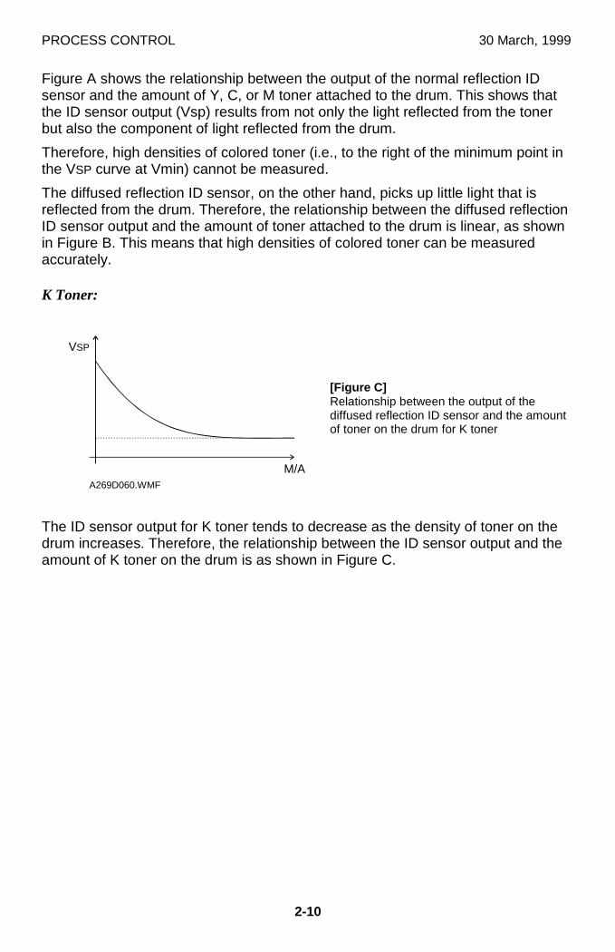
PROCESS CONTROL 30 March, 1999
2-10
Figure A shows the relationship between the output of the normal reflection IDsensor and the amount of Y, C, or M toner attached to the drum. This shows thatthe ID sensor output (Vsp) results from not only the light reflected from the tonerbut also the component of light reflected from the drum.
Therefore, high densities of colored toner (i.e., to the right of the minimum point inthe VSP curve at Vmin) cannot be measured.
The diffused reflection ID sensor, on the other hand, picks up little light that isreflected from the drum. Therefore, the relationship between the diffused reflectionID sensor output and the amount of toner attached to the drum is linear, as shownin Figure B. This means that high densities of colored toner can be measuredaccurately.
K Toner:
The ID sensor output for K toner tends to decrease as the density of toner on thedrum increases. Therefore, the relationship between the ID sensor output and theamount of K toner on the drum is as shown in Figure C.
A269D060.WMF
[Figure C]Relationship between the output of thediffused reflection ID sensor and the amountof toner on the drum for K toner
VSP
M/A
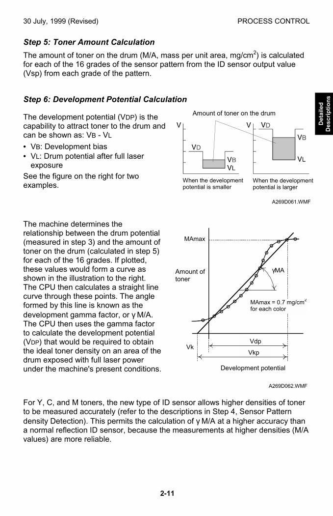
30 July, 1999 (Revised) PROCESS CONTROL
2-11
Detailed
Descriptions
Step 5: Toner Amount Calculation
The amount of toner on the drum (M/A, mass per unit area, mg/cm2) is calculatedfor each of the 16 grades of the sensor pattern from the ID sensor output value(Vsp) from each grade of the pattern.
Step 6: Development Potential Calculation
The development potential (VDP) is thecapability to attract toner to the drum andcan be shown as: VB - VL
• VB: Development bias• VL: Drum potential after full laser
exposure
See the figure on the right for twoexamples.
The machine determines therelationship between the drum potential(measured in step 3) and the amount oftoner on the drum (calculated in step 5)for each of the 16 grades. If plotted,these values would form a curve asshown in the illustration to the right.The CPU then calculates a straight linecurve through these points. The angleformed by this line is known as thedevelopment gamma factor, or γ M/A.The CPU then uses the gamma factorto calculate the development potential(VDP) that would be required to obtainthe ideal toner density on an area of thedrum exposed with full laser powerunder the machine's present conditions.
For Y, C, and M toners, the new type of ID sensor allows higher densities of tonerto be measured accurately (refer to the descriptions in Step 4, Sensor Patterndensity Detection). This permits the calculation of γ M/A at a higher accuracy thana normal reflection ID sensor, because the measurements at higher densities (M/Avalues) are more reliable.
A269D061.WMF
γMA
Vkp
VdpVk
MAmax
A269D062.WMF
Amount of toner on the drum
When the developmentpotential is smaller
When the developmentpotential is larger
Amount oftoner
Development potential
MAmax = 0.7 mg/cm2
for each color
PROCESS CONTROL 30 March, 1999
2-12
Step 7: Selecting the Optimum V D, VB, VL
The machine now adjusts VD, VB, and VL to try to bring the development potentialVDP to the ideal value. To do this, it uses a pointer table. This is a look-up table inROM of VDP against VD, VB, and VL.
The machine takes the value of VDP calculated in the previous section, and looksfor the value of VDP in the pointer table that is closest to this. The machine readsthe values of VD, VB, and VL that are in this row of the pointer table.
The machine will then use these values of VD, VB, and VL during copying until thenext process control self check. These values are designed to bring the actual VDPto the optimum value for the machine’s current condition.
• VD: Drum potential without exposure—to adjust this, the machine adjusts thecharge corona grid voltage (VG)
• VL: Drum potential with the strongest exposure—to adjust this, the machineadjusts the laser diode input current (ILD)
• VB: Development bias
30 March, 1999 PROCESS CONTROL
2-13
Det
aile
dD
escr
iptio
ns
2.1.5 TONER SUPPLY CONTROL
This machine uses fuzzy logic to control the amount of toner supplied to thedevelopment unit so that the development capacity does not fluctuate due to tonerconsumption, toner supply, agitation, or extended periods of nonuse. This control isaccomplished using the sense data from the drum potential sensor, toner endsensor, ID sensor, and TD sensor. This copier starts toner supply control bykeeping the toner density in the developer constant using the TD sensor. It thensenses the amount of toner on the drum using the ID sensor pattern. The ID sensorsends the pattern data back to the toner supply control mechanism and the amountof toner on the drum surface (image density) then becomes the target. The TDsensor provides a stable base point for toner supply and thus avoids runaway feed-back of toner supply. The basic input/output parameters that this copier usesduring toner supply control are listed below.
1. Targets to be sensed1) Density of the toner read by the TD sensor2) Amount of toner attached to the drum sensed by the ID sensor3) Pixel count
2. Target to be controlledToner supply clutch on time
Toner Supply Control Modes
This copier controls the supply of toner in three modes.
1. Fuzzy logic Control ModeDefault toner supply control mode. The TD sensor, ID sensor, and pixel countare used in this mode.
2. Proportional Control ModeThis mode is used when an ID sensor becomes faulty. Only the TD sensor isused to control toner supply.
3. Fixed Supply ModeThis mode is used when both the TD sensor and ID sensor become faulty.
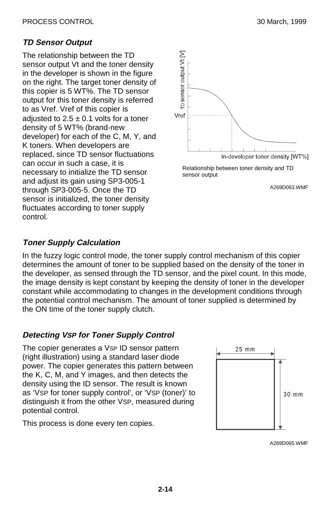
PROCESS CONTROL 30 March, 1999
2-14
TD Sensor Output
The relationship between the TDsensor output Vt and the toner densityin the developer is shown in the figureon the right. The target toner density ofthis copier is 5 WT%. The TD sensoroutput for this toner density is referredto as Vref. Vref of this copier isadjusted to 2.5 ± 0.1 volts for a tonerdensity of 5 WT% (brand-newdeveloper) for each of the C, M, Y, andK toners. When developers arereplaced, since TD sensor fluctuationscan occur in such a case, it isnecessary to initialize the TD sensorand adjust its gain using SP3-005-1through SP3-005-5. Once the TDsensor is initialized, the toner densityfluctuates according to toner supplycontrol.
Toner Supply Calculation
In the fuzzy logic control mode, the toner supply control mechanism of this copierdetermines the amount of toner to be supplied based on the density of the toner inthe developer, as sensed through the TD sensor, and the pixel count. In this mode,the image density is kept constant by keeping the density of toner in the developerconstant while accommodating to changes in the development conditions throughthe potential control mechanism. The amount of toner supplied is determined bythe ON time of the toner supply clutch.
Detecting V SP for Toner Supply Control
The copier generates a VSP ID sensor pattern(right illustration) using a standard laser diodepower. The copier generates this pattern betweenthe K, C, M, and Y images, and then detects thedensity using the ID sensor. The result is knownas ‘VSP for toner supply control’, or ‘VSP (toner)’ todistinguish it from the other VSP, measured duringpotential control.
This process is done every ten copies.
A269D063.WMF
������������������������������������������
25 mm
30 mm
A269D065.WMF
Relationship between toner density and TDsensor output
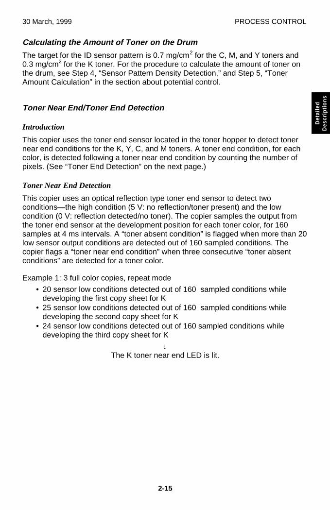
30 March, 1999 PROCESS CONTROL
2-15
Det
aile
dD
escr
iptio
ns
Calculating the Amount of Toner on the Drum
The target for the ID sensor pattern is 0.7 mg/cm2 for the C, M, and Y toners and0.3 mg/cm2 for the K toner. For the procedure to calculate the amount of toner onthe drum, see Step 4, “Sensor Pattern Density Detection,” and Step 5, “TonerAmount Calculation” in the section about potential control.
Toner Near End/Toner End Detection
Introduction
This copier uses the toner end sensor located in the toner hopper to detect tonernear end conditions for the K, Y, C, and M toners. A toner end condition, for eachcolor, is detected following a toner near end condition by counting the number ofpixels. (See “Toner End Detection” on the next page.)
Toner Near End Detection
This copier uses an optical reflection type toner end sensor to detect twoconditions—the high condition (5 V: no reflection/toner present) and the lowcondition (0 V: reflection detected/no toner). The copier samples the output fromthe toner end sensor at the development position for each toner color, for 160samples at 4 ms intervals. A “toner absent condition” is flagged when more than 20low sensor output conditions are detected out of 160 sampled conditions. Thecopier flags a “toner near end condition” when three consecutive “toner absentconditions” are detected for a toner color.
Example 1: 3 full color copies, repeat mode
• 20 sensor low conditions detected out of 160 sampled conditions whiledeveloping the first copy sheet for K
• 25 sensor low conditions detected out of 160 sampled conditions whiledeveloping the second copy sheet for K
• 24 sensor low conditions detected out of 160 sampled conditions whiledeveloping the third copy sheet for K
↓The K toner near end LED is lit.
PROCESS CONTROL 30 July, 1999 (Revised)
2-16
Example 2: 4 full color copies, repeat mode
• 20 sensor low conditions detected out of 160 sampled conditions whiledeveloping the first copy sheet for Y
• 19 sensor low conditions detected out of 160 sampled conditions whiledeveloping the second copy sheet for Y
• 21 sensor low conditions detected out of 160 sampled conditions whiledeveloping the third copy sheet for Y
• 25 sensor low conditions detected out of 160 sampled conditions whiledeveloping the fourth copy sheet for Y
• 21 sensor low conditions detected out of 160 sampled conditions whiledeveloping the fifth copy sheet for Y
↓The Y toner near end LED is lit.
Toner End Detection
After a toner near end is indicated, the toner end condition is reached when theIPU pixel counter counts up the equivalent of 10 A4 sheets of pixels (100%coverage) for that color.
The machine can copy/print at least 10 sheets after the toner near end condition issignaled. There are two possible cases as follows:
1. The toner end condition occurs before 10 sheets are printed: In this casecopying stops after 10 sheets are printed. This is true regardless of paper size.
2. Ten sheets (of any size) are printed before toner end occurs: In this casecopying stops when the toner end condition occurs.
Toner End Recovery
The copier enters the recovery process in the following cases:
1. The front door is opened and a toner cartridge is removed or inserted.This is regarded as an ordinary replacement procedure for the toner cartridge.• When the door is closed, the copier moves the next to-be-replaced color
toner cartridge to the replacement position.
↓↓↓↓• Replace the toner cartridge.
↓↓↓↓• The copier starts toner end recovery processing after the toner cartridge is
replaced and the front door is closed.
NOTE: If recovery is needed for two colors, the copier proceeds with the nextcolor if the door is opened or if the user specifies at the operation panelthat the first color should be skipped.
2. If the copier is turned off and on, it assumes that toner cartridges for all colorshave been replaced and starts toner end recovery processing for all colors.
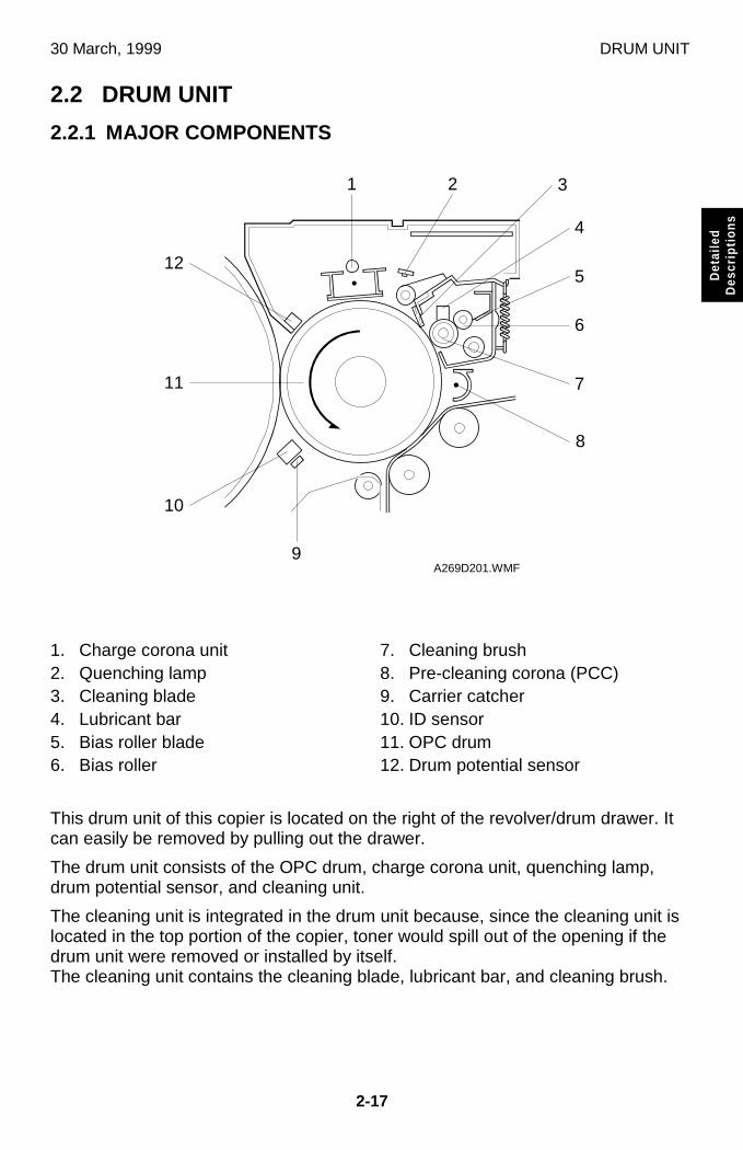
30 March, 1999 DRUM UNIT
2-17
Det
aile
dD
escr
iptio
ns
2.2 DRUM UNIT
2.2.1 MAJOR COMPONENTS
1. Charge corona unit2. Quenching lamp3. Cleaning blade4. Lubricant bar5. Bias roller blade6. Bias roller
7. Cleaning brush8. Pre-cleaning corona (PCC)9. Carrier catcher10. ID sensor11. OPC drum12. Drum potential sensor
This drum unit of this copier is located on the right of the revolver/drum drawer. Itcan easily be removed by pulling out the drawer.
The drum unit consists of the OPC drum, charge corona unit, quenching lamp,drum potential sensor, and cleaning unit.
The cleaning unit is integrated in the drum unit because, since the cleaning unit islocated in the top portion of the copier, toner would spill out of the opening if thedrum unit were removed or installed by itself.The cleaning unit contains the cleaning blade, lubricant bar, and cleaning brush.
A269D201.WMF
1
4
2 3
5
8
7
6
10
11
12
9
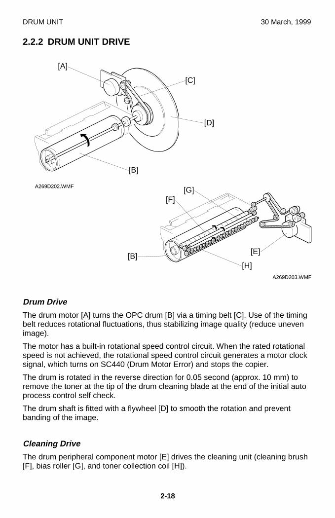
DRUM UNIT 30 March, 1999
2-18
2.2.2 DRUM UNIT DRIVE
Drum Drive
The drum motor [A] turns the OPC drum [B] via a timing belt [C]. Use of the timingbelt reduces rotational fluctuations, thus stabilizing image quality (reduce unevenimage).
The motor has a built-in rotational speed control circuit. When the rated rotationalspeed is not achieved, the rotational speed control circuit generates a motor clocksignal, which turns on SC440 (Drum Motor Error) and stops the copier.
The drum is rotated in the reverse direction for 0.05 second (approx. 10 mm) toremove the toner at the tip of the drum cleaning blade at the end of the initial autoprocess control self check.
The drum shaft is fitted with a flywheel [D] to smooth the rotation and preventbanding of the image.
Cleaning Drive
The drum peripheral component motor [E] drives the cleaning unit (cleaning brush[F], bias roller [G], and toner collection coil [H]).
A269D202.WMF
A269D203.WMF
[B][E]
[F][G]
[H]
[A]
[B]
[C]
[D]
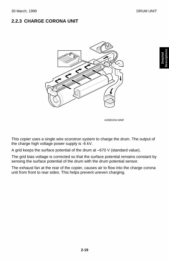
30 March, 1999 DRUM UNIT
2-19
Det
aile
dD
escr
iptio
ns
2.2.3 CHARGE CORONA UNIT
This copier uses a single wire scorotron system to charge the drum. The output ofthe charge high voltage power supply is -6 kV.
A grid keeps the surface potential of the drum at –670 V (standard value).
The grid bias voltage is corrected so that the surface potential remains constant bysensing the surface potential of the drum with the drum potential sensor.
The exhaust fan at the rear of the copier, causes air to flow into the charge coronaunit from front to rear sides. This helps prevent uneven charging.
A269D204.WMF
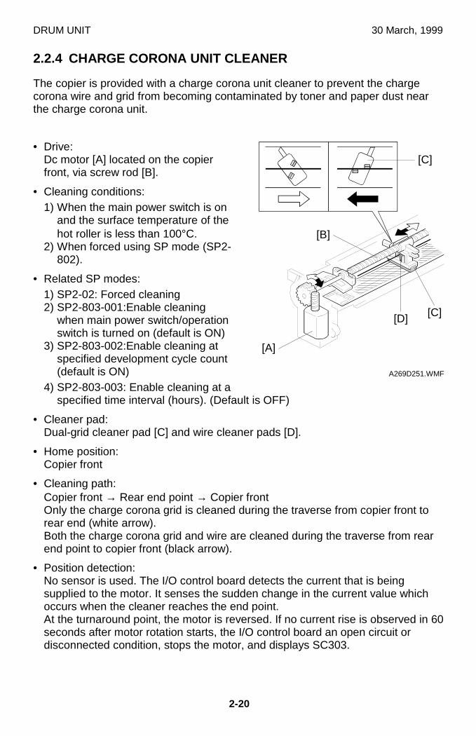
DRUM UNIT 30 March, 1999
2-20
2.2.4 CHARGE CORONA UNIT CLEANER
The copier is provided with a charge corona unit cleaner to prevent the chargecorona wire and grid from becoming contaminated by toner and paper dust nearthe charge corona unit.
• Drive:Dc motor [A] located on the copierfront, via screw rod [B].
• Cleaning conditions:1) When the main power switch is on
and the surface temperature of thehot roller is less than 100°C.
2) When forced using SP mode (SP2-802).
• Related SP modes:1) SP2-02: Forced cleaning2) SP2-803-001:Enable cleaning
when main power switch/operationswitch is turned on (default is ON)
3) SP2-803-002:Enable cleaning atspecified development cycle count(default is ON)
4) SP2-803-003: Enable cleaning at aspecified time interval (hours). (Default is OFF)
• Cleaner pad:Dual-grid cleaner pad [C] and wire cleaner pads [D].
• Home position:Copier front
• Cleaning path:Copier front → Rear end point → Copier frontOnly the charge corona grid is cleaned during the traverse from copier front torear end (white arrow).Both the charge corona grid and wire are cleaned during the traverse from rearend point to copier front (black arrow).
• Position detection:No sensor is used. The I/O control board detects the current that is beingsupplied to the motor. It senses the sudden change in the current value whichoccurs when the cleaner reaches the end point.At the turnaround point, the motor is reversed. If no current rise is observed in 60seconds after motor rotation starts, the I/O control board an open circuit ordisconnected condition, stops the motor, and displays SC303.
A269D251.WMF
[D]
[C]
[A]
[B]
[C]
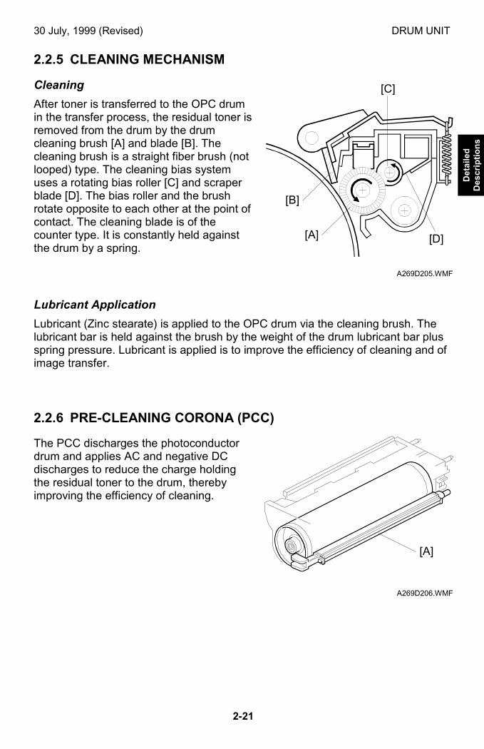
30 July, 1999 (Revised) DRUM UNIT
2-21
Det
aile
dD
escr
ipti
on
s
2.2.5 CLEANING MECHANISM
Cleaning
After toner is transferred to the OPC drumin the transfer process, the residual toner isremoved from the drum by the drumcleaning brush [A] and blade [B]. Thecleaning brush is a straight fiber brush (notlooped) type. The cleaning bias systemuses a rotating bias roller [C] and scraperblade [D]. The bias roller and the brushrotate opposite to each other at the point ofcontact. The cleaning blade is of thecounter type. It is constantly held againstthe drum by a spring.
Lubricant Application
Lubricant (Zinc stearate) is applied to the OPC drum via the cleaning brush. Thelubricant bar is held against the brush by the weight of the drum lubricant bar plusspring pressure. Lubricant is applied is to improve the efficiency of cleaning and ofimage transfer.
2.2.6 PRE-CLEANING CORONA (PCC)
The PCC discharges the photoconductordrum and applies AC and negative DCdischarges to reduce the charge holdingthe residual toner to the drum, therebyimproving the efficiency of cleaning.
A269D205.WMF
A269D206.WMF
[D][A]
[B]
[C]
[A]
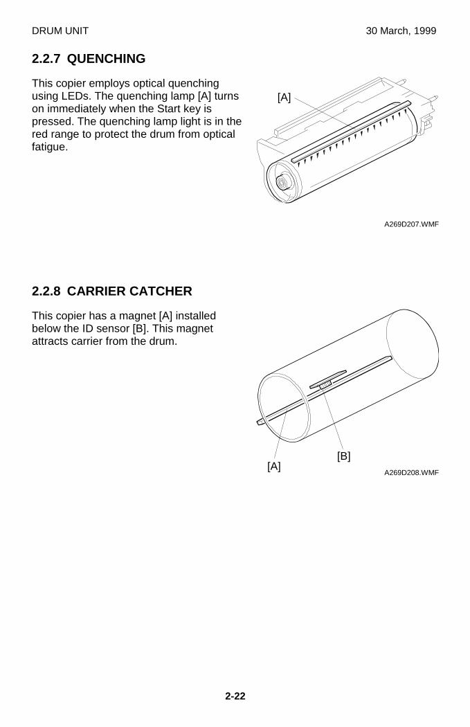
DRUM UNIT 30 March, 1999
2-22
2.2.7 QUENCHING
This copier employs optical quenchingusing LEDs. The quenching lamp [A] turnson immediately when the Start key ispressed. The quenching lamp light is in thered range to protect the drum from opticalfatigue.
2.2.8 CARRIER CATCHER
This copier has a magnet [A] installedbelow the ID sensor [B]. This magnetattracts carrier from the drum.
A269D207.WMF
A269D208.WMF
[A]
[A][B]
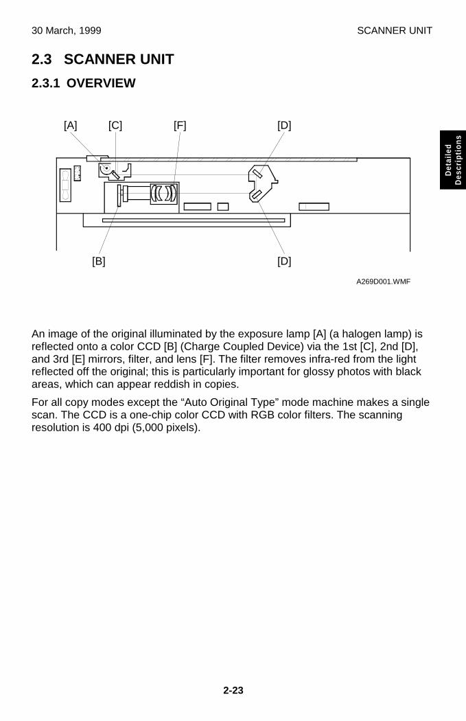
30 March, 1999 SCANNER UNIT
2-23
Det
aile
dD
escr
iptio
ns
2.3 SCANNER UNIT
2.3.1 OVERVIEW
An image of the original illuminated by the exposure lamp [A] (a halogen lamp) isreflected onto a color CCD [B] (Charge Coupled Device) via the 1st [C], 2nd [D],and 3rd [E] mirrors, filter, and lens [F]. The filter removes infra-red from the lightreflected off the original; this is particularly important for glossy photos with blackareas, which can appear reddish in copies.
For all copy modes except the “Auto Original Type” mode machine makes a singlescan. The CCD is a one-chip color CCD with RGB color filters. The scanningresolution is 400 dpi (5,000 pixels).
A269D001.WMF
[A] [C] [F] [D]
[D][B]
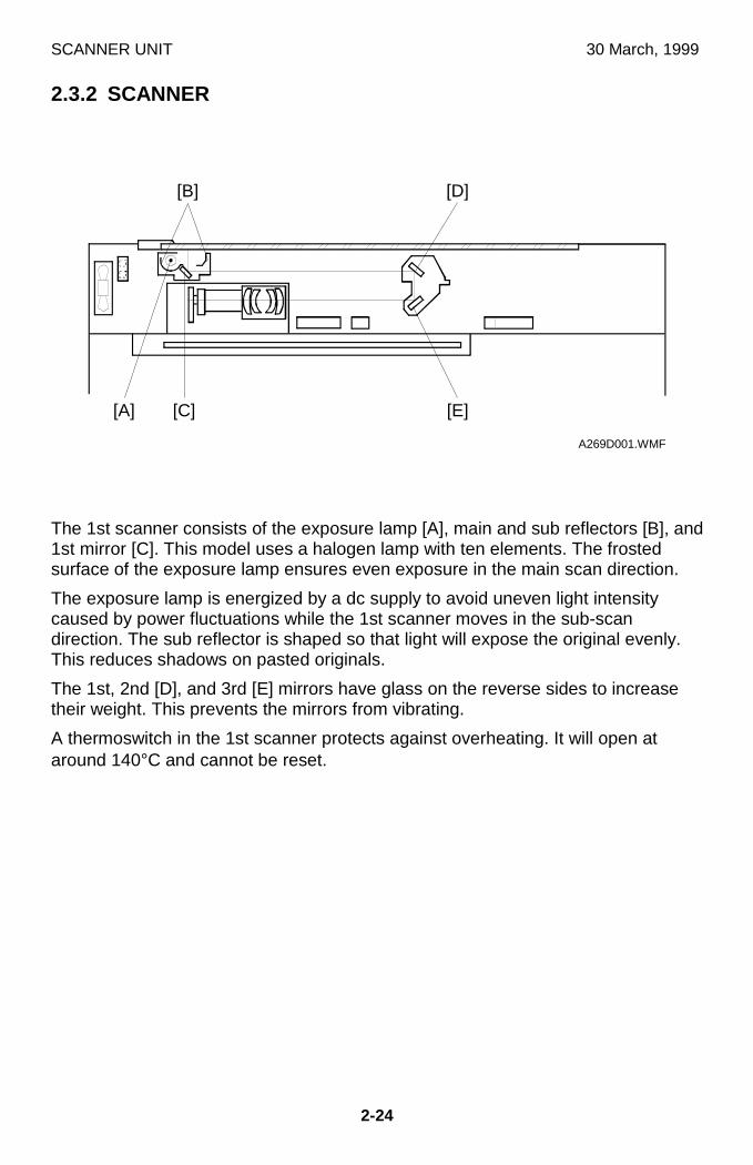
SCANNER UNIT 30 March, 1999
2-24
2.3.2 SCANNER
The 1st scanner consists of the exposure lamp [A], main and sub reflectors [B], and1st mirror [C]. This model uses a halogen lamp with ten elements. The frostedsurface of the exposure lamp ensures even exposure in the main scan direction.
The exposure lamp is energized by a dc supply to avoid uneven light intensitycaused by power fluctuations while the 1st scanner moves in the sub-scandirection. The sub reflector is shaped so that light will expose the original evenly.This reduces shadows on pasted originals.
The 1st, 2nd [D], and 3rd [E] mirrors have glass on the reverse sides to increasetheir weight. This prevents the mirrors from vibrating.
A thermoswitch in the 1st scanner protects against overheating. It will open ataround 140°C and cannot be reset.
A269D001.WMF
[D]
[E][A]
[B]
[C]
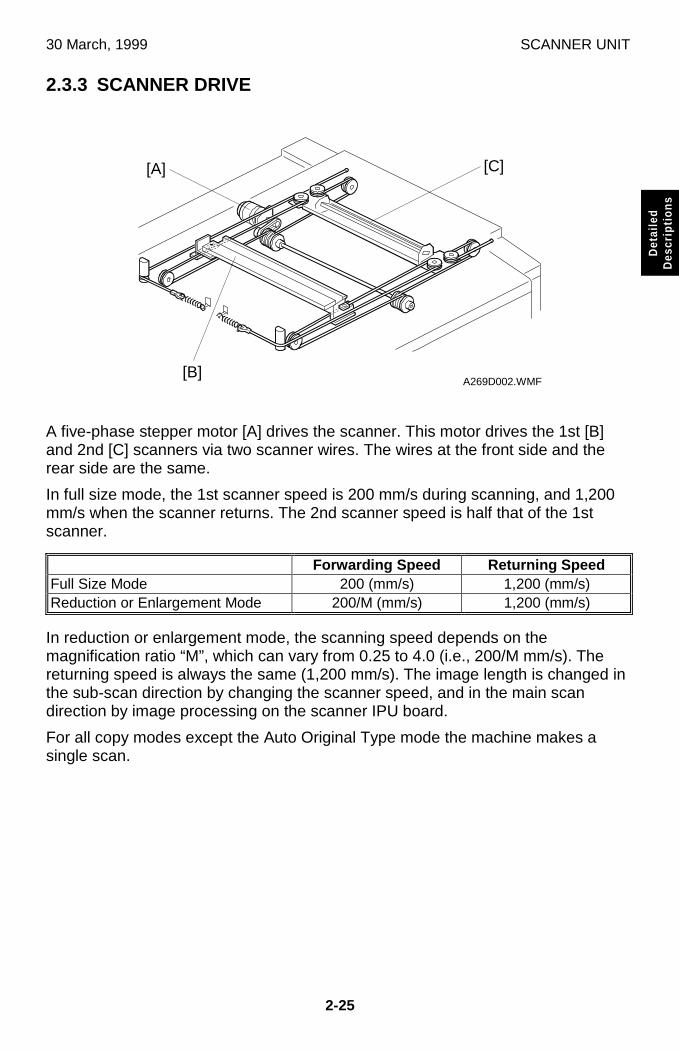
30 March, 1999 SCANNER UNIT
2-25
Det
aile
dD
escr
iptio
ns
2.3.3 SCANNER DRIVE
A five-phase stepper motor [A] drives the scanner. This motor drives the 1st [B]and 2nd [C] scanners via two scanner wires. The wires at the front side and therear side are the same.
In full size mode, the 1st scanner speed is 200 mm/s during scanning, and 1,200mm/s when the scanner returns. The 2nd scanner speed is half that of the 1stscanner.
Forwarding Speed Returning SpeedFull Size Mode 200 (mm/s) 1,200 (mm/s)Reduction or Enlargement Mode 200/M (mm/s) 1,200 (mm/s)
In reduction or enlargement mode, the scanning speed depends on themagnification ratio “M”, which can vary from 0.25 to 4.0 (i.e., 200/M mm/s). Thereturning speed is always the same (1,200 mm/s). The image length is changed inthe sub-scan direction by changing the scanner speed, and in the main scandirection by image processing on the scanner IPU board.
For all copy modes except the Auto Original Type mode the machine makes asingle scan.
A269D002.WMF
[A]
[B]
[C]
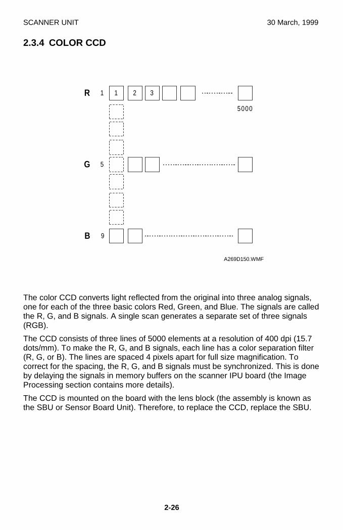
SCANNER UNIT 30 March, 1999
2-26
2.3.4 COLOR CCD
The color CCD converts light reflected from the original into three analog signals,one for each of the three basic colors Red, Green, and Blue. The signals are calledthe R, G, and B signals. A single scan generates a separate set of three signals(RGB).
The CCD consists of three lines of 5000 elements at a resolution of 400 dpi (15.7dots/mm). To make the R, G, and B signals, each line has a color separation filter(R, G, or B). The lines are spaced 4 pixels apart for full size magnification. Tocorrect for the spacing, the R, G, and B signals must be synchronized. This is doneby delaying the signals in memory buffers on the scanner IPU board (the ImageProcessing section contains more details).
The CCD is mounted on the board with the lens block (the assembly is known asthe SBU or Sensor Board Unit). Therefore, to replace the CCD, replace the SBU.
1
5
9
2 31R
G
B
5000
A269D150.WMF
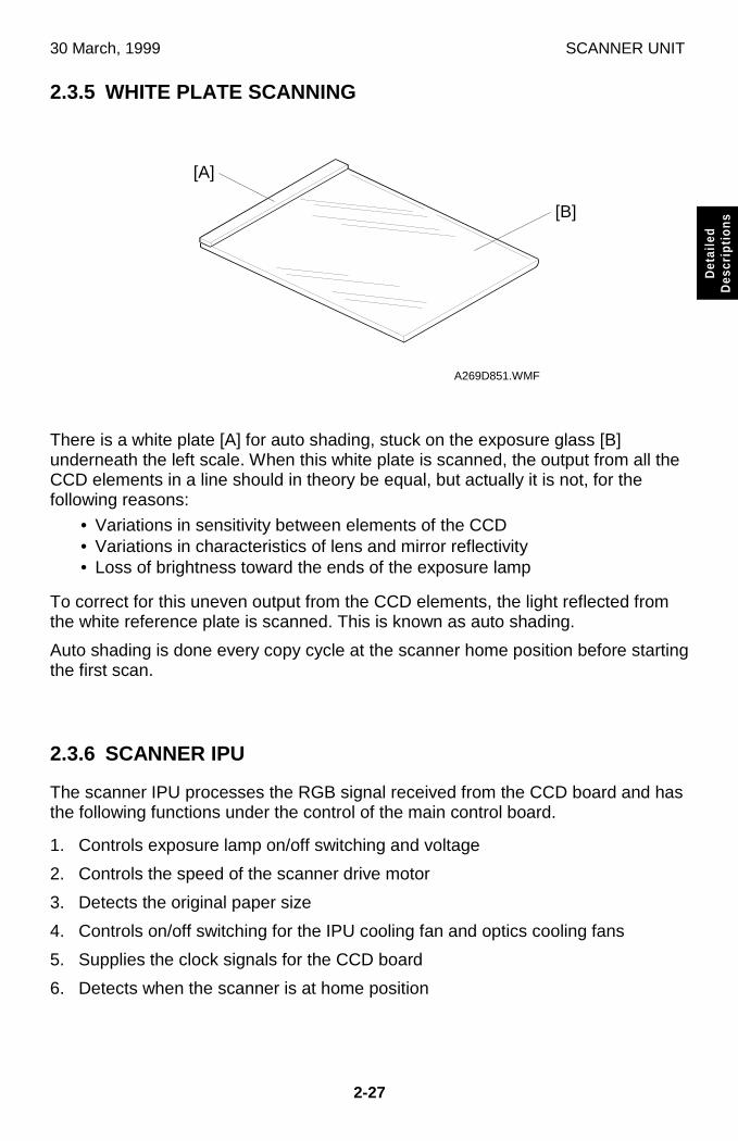
30 March, 1999 SCANNER UNIT
2-27
Det
aile
dD
escr
iptio
ns
2.3.5 WHITE PLATE SCANNING
There is a white plate [A] for auto shading, stuck on the exposure glass [B]underneath the left scale. When this white plate is scanned, the output from all theCCD elements in a line should in theory be equal, but actually it is not, for thefollowing reasons:
• Variations in sensitivity between elements of the CCD• Variations in characteristics of lens and mirror reflectivity• Loss of brightness toward the ends of the exposure lamp
To correct for this uneven output from the CCD elements, the light reflected fromthe white reference plate is scanned. This is known as auto shading.
Auto shading is done every copy cycle at the scanner home position before startingthe first scan.
2.3.6 SCANNER IPU
The scanner IPU processes the RGB signal received from the CCD board and hasthe following functions under the control of the main control board.
1. Controls exposure lamp on/off switching and voltage
2. Controls the speed of the scanner drive motor
3. Detects the original paper size
4. Controls on/off switching for the IPU cooling fan and optics cooling fans
5. Supplies the clock signals for the CCD board
6. Detects when the scanner is at home position
A269D851.WMF
[A]
[B]
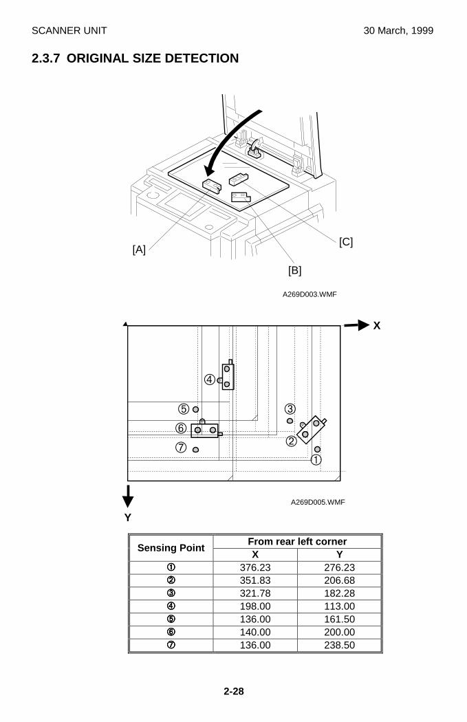
SCANNER UNIT 30 March, 1999
2-28
2.3.7 ORIGINAL SIZE DETECTION
From rear left cornerSensing Point
X Y���� 376.23 276.23���� 351.83 206.68���� 321.78 182.28���� 198.00 113.00���� 136.00 161.50���� 140.00 200.00���� 136.00 238.50
A269D003.WMF
A269D005.WMF
[B]
[A][C]
�
�
�
�
�
�
�
X
Y
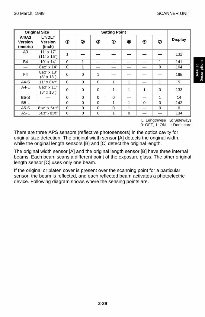
30 March, 1999 SCANNER UNIT
2-29
Det
aile
dD
escr
iptio
ns
Original Size Setting PointA4/A3
Version(metric)
LT/DLTVersion(inch)
���� ���� ���� ���� ���� ���� ����Display
A3 11" x 17"(11" x 15")
1 — — — — — — 132
B4 10" x 14" 0 1 — — — — 1 141— 81/2" x 14" 0 1 — — — — 0 164
F481/2" x 13"(8" x 13")
0 0 1 — — — — 165
A4-S 11" x 81/2" 0 0 0 1 1 — 1 5A4-L 81/2" x 11"
(8" x 10")0 0 0 1 1 1 0 133
B5-S — 0 0 0 0 — — 1 14B5-L — 0 0 0 1 1 0 0 142A5-S 81/2" x 51/2" 0 0 0 0 1 — 0 6A5-L 51/2" x 81/2" 0 0 0 1 0 — — 134
L: Lengthwise S: Sideways0: OFF, 1: ON —: Don’t care
There are three APS sensors (reflective photosensors) in the optics cavity fororiginal size detection. The original width sensor [A] detects the original width,while the original length sensors [B] and [C] detect the original length.
The original width sensor [A] and the original length sensor [B] have three internalbeams. Each beam scans a different point of the exposure glass. The other originallength sensor [C] uses only one beam.
If the original or platen cover is present over the scanning point for a particularsensor, the beam is reflected, and each reflected beam activates a photoelectricdevice. Following diagram shows where the sensing points are.
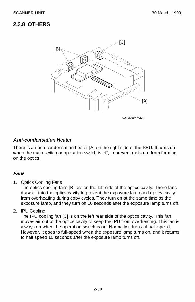
SCANNER UNIT 30 March, 1999
2-30
2.3.8 OTHERS
Anti-condensation Heater
There is an anti-condensation heater [A] on the right side of the SBU. It turns onwhen the main switch or operation switch is off, to prevent moisture from formingon the optics.
Fans
1. Optics Cooling FansThe optics cooling fans [B] are on the left side of the optics cavity. There fansdraw air into the optics cavity to prevent the exposure lamp and optics cavityfrom overheating during copy cycles. They turn on at the same time as theexposure lamp, and they turn off 10 seconds after the exposure lamp turns off.
2. IPU CoolingThe IPU cooling fan [C] is on the left rear side of the optics cavity. This fanmoves air out of the optics cavity to keep the IPU from overheating. This fan isalways on when the operation switch is on. Normally it turns at half-speed.However, it goes to full-speed when the exposure lamp turns on, and it returnsto half speed 10 seconds after the exposure lamp turns off.
A269D004.WMF
[B]
[A]
[C]
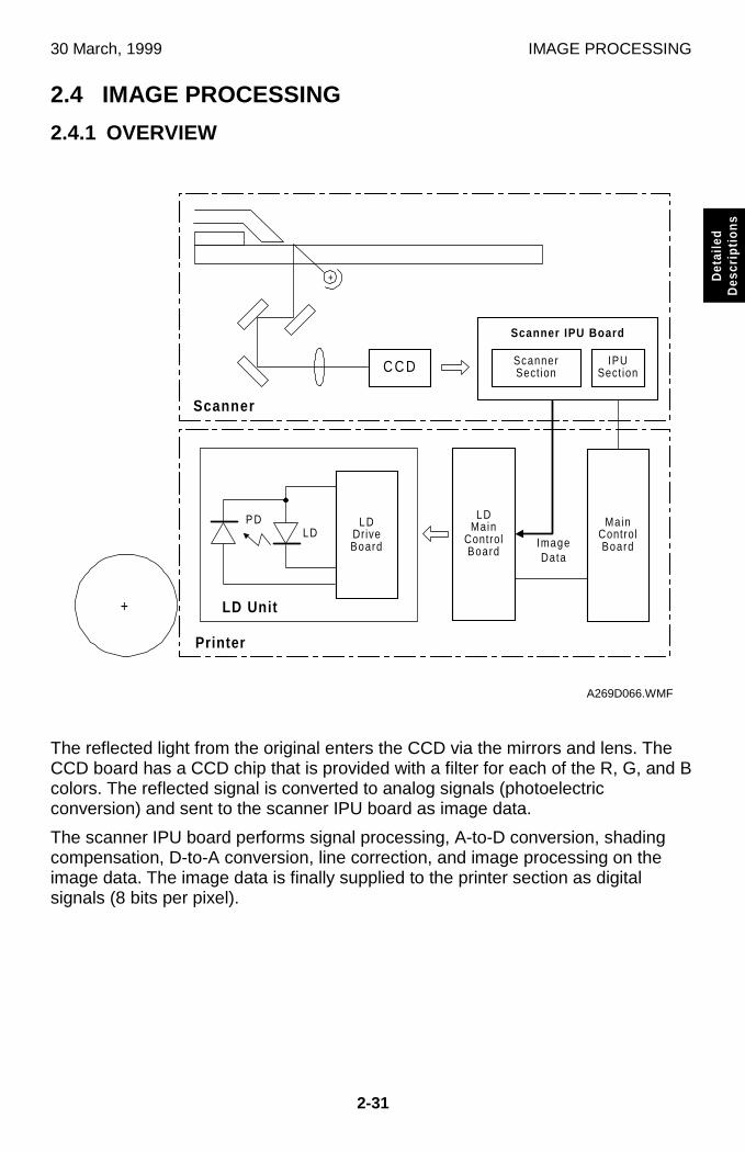
30 March, 1999 IMAGE PROCESSING
2-31
Det
aile
dD
escr
iptio
ns
2.4 IMAGE PROCESSING
2.4.1 OVERVIEW
The reflected light from the original enters the CCD via the mirrors and lens. TheCCD board has a CCD chip that is provided with a filter for each of the R, G, and Bcolors. The reflected signal is converted to analog signals (photoelectricconversion) and sent to the scanner IPU board as image data.
The scanner IPU board performs signal processing, A-to-D conversion, shadingcompensation, D-to-A conversion, line correction, and image processing on theimage data. The image data is finally supplied to the printer section as digitalsignals (8 bits per pixel).
�������������+
C C D ScannerSect ion
IPUSect ion
Scanner
LDDriveBoard
LDMain
ControlBoard
Printer
MainControlBoard
LD Unit
LDP D
Scanner IPU Board
+
ImageData
A269D066.WMF
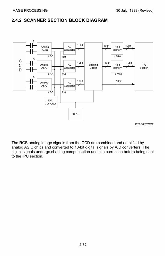
IMAGE PROCESSING 30 July, 1999 (Revised)
2-32
2.4.2 SCANNER SECTION BLOCK DIAGRAM
The RGB analog image signals from the CCD are combined and amplified byanalog ASIC chips and converted to 10-bit digital signals by A/D converters. Thedigital signals undergo shading compensation and line correction before being sentto the IPU section.
CCD
10bit 10bit
10bit10bit
10bit10bit
10bit
10bit
Ref
Ref
Ref
AGC
AGC
AGC
R
G
B2 Mbit
4 Mbit
AnalogASIC
ADConverter
ShadingCircuit
FieldMemory
IPUSection
CPU
D/AConverter
AnalogASIC
ADConverter
FieldMemory
AnalogASIC
ADConverter
A269D067.WMF
CCD
30 March, 1999 IMAGE PROCESSING
2-33
Det
aile
dD
escr
iptio
ns
2.4.3 SCANNER FUNCTIONS
Photoelectric Conversion
The color CCD converts the light reflected from the original into RGB analogsignals (6.615 MHz for each signal: even-pixel and odd-pixel). Each CCD line has5,000 pixels and the resolution is 400 dpi (15.7 pixels/mm).
Signal Processing (Analog ASIC)
This analog ASIC provides the following three analog signal processing functions:
(1) Signal AmplificationOdd-pixel and even-pixel RGB analog signals from the CCD are amplified byoperational amplifiers.
(2) Signal CompositionThe amplified signals (even-pixel and odd-pixel for each RGB color) are combinedby the MPX before A/D conversion.
(3) Feedback
The CPU on the scanner IPU board receives the feedback data for white level andblack level from the shading circuits and feeds it to the ASICs through the D/Aconverter. The feedback data from the CPU are updated every time the mainswitch is turned on.
A/D Conversion
The A/D conversion block converts the analog signals (CCD output) to 10-bit (1024gradations) digital signals.

IMAGE PROCESSING 30 March, 1999
2-34
Shading Compensation Circuit
(1) Shading compensation
Before scanning each original, themachine generates a reference whitewaveform (also known as "white shadingdata") by scanning 5 mm of the whitereference plate [A] in the sub-scandirection (this equals 79 lines at 100%magnification).
The white shading data is calculated foreach pixel across the main scan. To dothis for a particular pixel, it takes the whitelevels for that pixel on each of the main scan lines taken from the white referenceplate, and calculates a value from these. The white waveform is made by repeatingthis process for each pixel across the main scan.
To improve image reproduction for high density areas, the machine also measuresthe black shading data. It does this by reading the black video level at the first 4pixels of the CCD, which should be black because these pixels are masked off.The average of the 4 pixels is represented as the black shading data for one CCDscan line.
The video signal for each pixel obtained during image scanning is corrected by theshading circuit as follows:
(Data scanned for each pixel) - (Black correction data)
(White correction data for each pixel) - (Black correction data)x 1023
The white shading data are updated before every scanning. The black shadingdata are updated every scan line. The white shading data corrects the image datafor irregularities in the CCD and the optics across the main scan. The black
����������+
A269D068.WMF
1023
01 l ine1 l ine
Whi teCorrect ion
BlackCorrect ion
A269D069.WMF
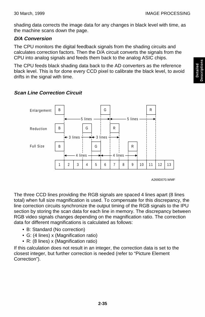
30 March, 1999 IMAGE PROCESSING
2-35
Det
aile
dD
escr
iptio
ns
shading data corrects the image data for any changes in black level with time, asthe machine scans down the page.
D/A Conversion
The CPU monitors the digital feedback signals from the shading circuits andcalculates correction factors. Then the D/A circuit converts the signals from theCPU into analog signals and feeds them back to the analog ASIC chips.
The CPU feeds black shading data back to the AD converters as the referenceblack level. This is for done every CCD pixel to calibrate the black level, to avoiddrifts in the signal with time.
Scan Line Correction Circuit
The three CCD lines providing the RGB signals are spaced 4 lines apart (8 linestotal) when full size magnification is used. To compensate for this discrepancy, theline correction circuits synchronize the output timing of the RGB signals to the IPUsection by storing the scan data for each line in memory. The discrepancy betweenRGB video signals changes depending on the magnification ratio. The correctiondata for different magnifications is calculated as follows:
• B: Standard (No correction)• G: (4 lines) x (Magnification ratio)• R: (8 lines) x (Magnification ratio)
If this calculation does not result in an integer, the correction data is set to theclosest integer, but further correction is needed (refer to “Picture ElementCorrection”).
B
B
B
1 2 3 4 5 6 7 8 9 10 11 12 13
G R
G R
G R
5 l ines 5 l ines
3 l ines3 l ines
4 l ines 4 l ines
Enlargement
Reduct ion
Ful l Size
A269D070.WMF
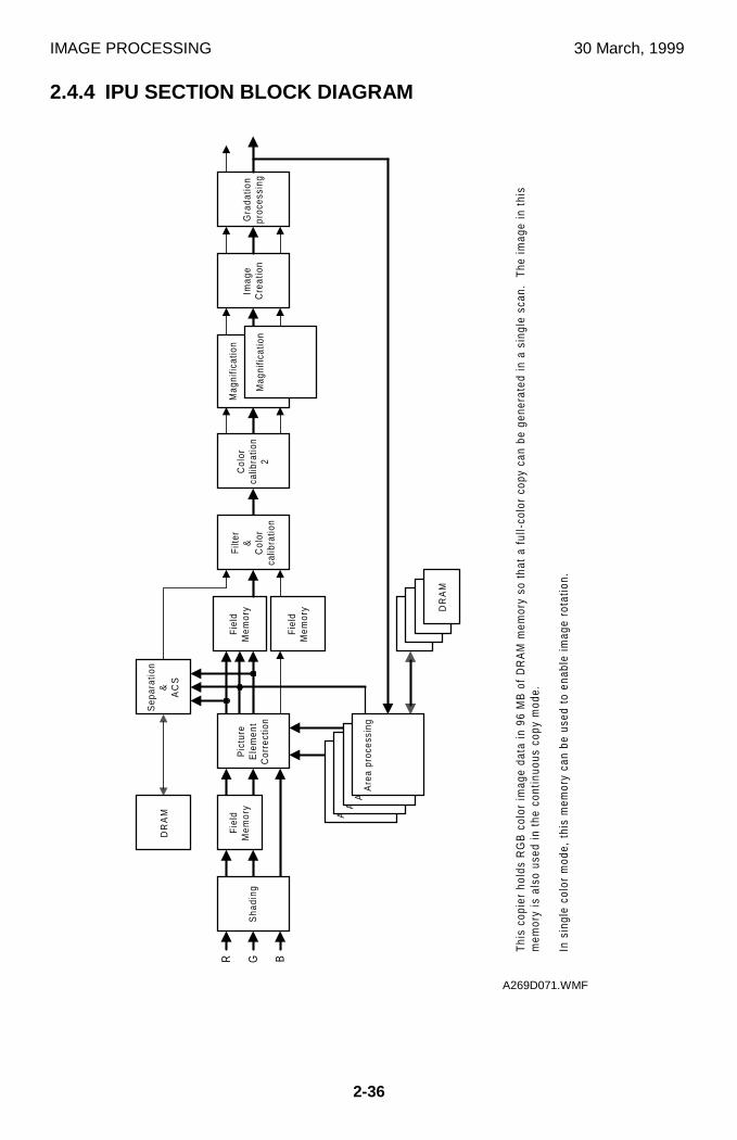
IMAGE PROCESSING 30 March, 1999
2-36
2.4.4 IPU SECTION BLOCK DIAGRAM
DR
AM
R
Sep
arat
ion
&A
CS
Fie
ldM
emor
y
Fie
ldM
emor
y
Mag
nific
atio
n
Mag
nific
atio
nIm
age
Cre
atio
nG
rada
tion
proc
essi
ngG B
Are
a pr
oces
sing
Are
a pr
oces
sing
Are
a pr
oces
sing
Are
a pr
oces
sing
DR
AM
DR
AM
DR
AM
DR
AM
Thi
s co
pier
hol
ds R
GB
col
or im
age
data
in 9
6 M
B o
f D
RA
M m
emor
y so
tha
t a
full-
colo
r co
py c
an b
e ge
nera
ted
in a
sin
gle
scan
. T
he im
age
in t
his
mem
ory
is a
lso
used
in t
he c
ontin
uous
cop
y m
ode.
In s
ingl
e co
lor
mod
e, t
his
mem
ory
can
be u
sed
to e
nabl
e im
age
rota
tion.
Col
orca
libra
tion
2
Filte
r&
Col
orca
libra
tion
Fie
ldM
emor
yS
hadi
ngP
ictu
reE
lem
ent
Cor
rect
ion
A269D071.WMF
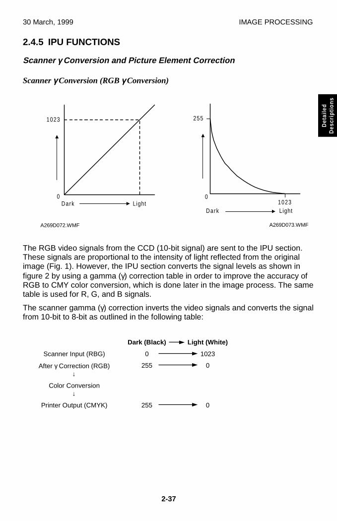
30 March, 1999 IMAGE PROCESSING
2-37
Det
aile
dD
escr
iptio
ns
2.4.5 IPU FUNCTIONS
Scanner γγγγ Conversion and Picture Element Correction
Scanner γγγγ Conversion (RGB γγγγ Conversion)
The RGB video signals from the CCD (10-bit signal) are sent to the IPU section.These signals are proportional to the intensity of light reflected from the originalimage (Fig. 1). However, the IPU section converts the signal levels as shown infigure 2 by using a gamma (γ) correction table in order to improve the accuracy ofRGB to CMY color conversion, which is done later in the image process. The sametable is used for R, G, and B signals.
The scanner gamma (γ) correction inverts the video signals and converts the signalfrom 10-bit to 8-bit as outlined in the following table:
Dark (Black) Light (White)
Scanner Input (RBG) 0 1023
After γ Correction (RGB)↓
255 0
Color Conversion↓
Printer Output (CMYK) 255 0
1023
Dark Light0
A269D072.WMF
255
01023LightDark
A269D073.WMF
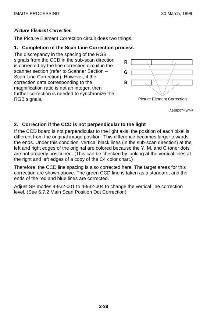
IMAGE PROCESSING 30 March, 1999
2-38
Picture Element Correction
The Picture Element Correction circuit does two things.
1. Completion of the Scan Line Correction processThe discrepancy in the spacing of the RGBsignals from the CCD in the sub-scan directionis corrected by the line correction circuit in thescanner section (refer to Scanner Section –Scan Line Correction). However, if thecorrection data corresponding to themagnification ratio is not an integer, thenfurther correction is needed to synchronize theRGB signals.
2. Correction if the CCD is not perpendicular to the lightIf the CCD board is not perpendicular to the light axis, the position of each pixel isdifferent from the original image position. This difference becomes larger towardsthe ends. Under this condition, vertical black lines (in the sub-scan direction) at theleft and right edges of the original are colored because the Y, M, and C toner dotsare not properly positioned. (This can be checked by looking at the vertical lines atthe right and left edges of a copy of the C4 color chart.)
Therefore, the CCD line spacing is also corrected here. The target areas for thiscorrection are shown above. The green CCD line is taken as a standard, and theends of the red and blue lines are corrected.
Adjust SP modes 4-932-001 to 4-932-004 to change the vertical line correctionlevel. (See 6.7.2 Main Scan Position Dot Correction)
��� ���
������
������
R
G
B
A269D074.WMF
Picture Element Correction
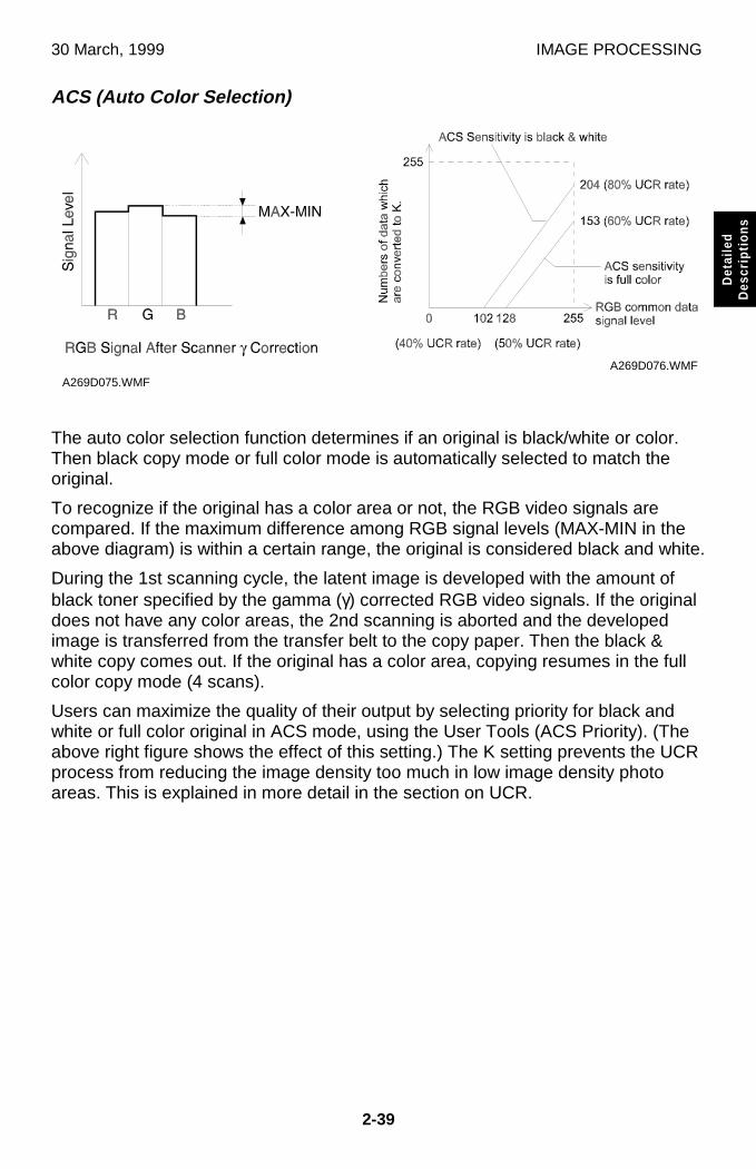
30 March, 1999 IMAGE PROCESSING
2-39
Det
aile
dD
escr
iptio
ns
ACS (Auto Color Selection)
The auto color selection function determines if an original is black/white or color.Then black copy mode or full color mode is automatically selected to match theoriginal.
To recognize if the original has a color area or not, the RGB video signals arecompared. If the maximum difference among RGB signal levels (MAX-MIN in theabove diagram) is within a certain range, the original is considered black and white.
During the 1st scanning cycle, the latent image is developed with the amount ofblack toner specified by the gamma (γ) corrected RGB video signals. If the originaldoes not have any color areas, the 2nd scanning is aborted and the developedimage is transferred from the transfer belt to the copy paper. Then the black &white copy comes out. If the original has a color area, copying resumes in the fullcolor copy mode (4 scans).
Users can maximize the quality of their output by selecting priority for black andwhite or full color original in ACS mode, using the User Tools (ACS Priority). (Theabove right figure shows the effect of this setting.) The K setting prevents the UCRprocess from reducing the image density too much in low image density photoareas. This is explained in more detail in the section on UCR.
A269D075.WMFA269D076.WMF
IMAGE PROCESSING 30 March, 1999
2-40
Automatic Original Type Selection
If this function is selected, the copier starts a pre-scan when the Start key ispressed. During the pre-scan, the copier detects two or more image features andidentifies the type of original.
Since the copier selects the mode that is most suited to the original, the selectedmode does not always match the specified mode. For example, the copier may notcopy text originals in the text mode.
The copier automatically selects the following 9 original modes:
Automatically selected original modes1) Text mode2) Printed text/photo3) Glossy text/photo4) Copied text/photo5) Printed photo6) Glossy photo7) Copied photo8) Marker pen9) Ink jet
NOTE: Mixed-type originals are disallowed because the copier cannot select anappropriate mode for such originals (they may be copied, however).
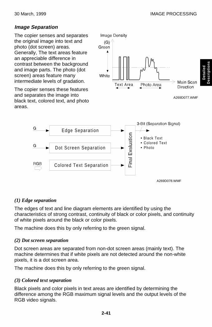
30 March, 1999 IMAGE PROCESSING
2-41
Det
aile
dD
escr
iptio
ns
Image Separation
The copier senses and separatesthe original image into text andphoto (dot screen) areas.Generally, The text areas featurean appreciable difference incontrast between the backgroundand image parts. The photo (dotscreen) areas feature manyintermediate levels of gradation.
The copier senses these featuresand separates the image intoblack text, colored text, and photoareas.
(1) Edge separation
The edges of text and line diagram elements are identified by using thecharacteristics of strong contrast, continuity of black or color pixels, and continuityof white pixels around the black or color pixels.
The machine does this by only referring to the green signal.
(2) Dot screen separation
Dot screen areas are separated from non-dot screen areas (mainly text). Themachine determines that if white pixels are not detected around the non-whitepixels, it is a dot screen area.
The machine does this by only referring to the green signal.
(3) Colored text separation
Black pixels and color pixels in text areas are identified by determining thedifference among the RGB maximum signal levels and the output levels of theRGB video signals.
Text Area
A269D077.WMF
Edge Separat ion
Dot Screen Separat ion
• Black Text• Colored Text• Photo
Colored Text Separat ion
A269D078.WMF
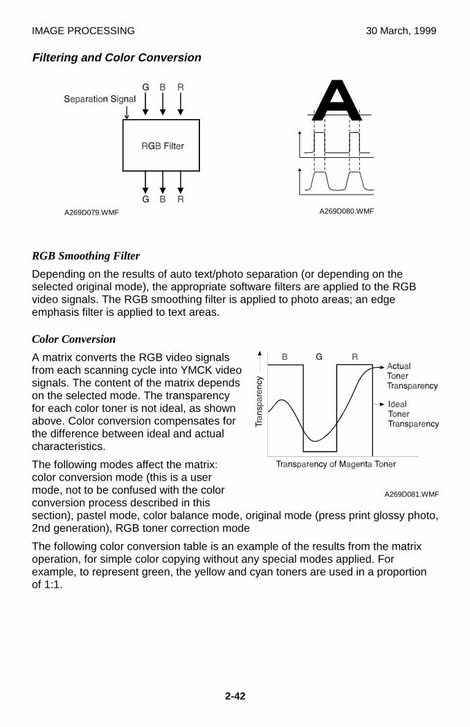
IMAGE PROCESSING 30 March, 1999
2-42
Filtering and Color Conversion
RGB Smoothing Filter
Depending on the results of auto text/photo separation (or depending on theselected original mode), the appropriate software filters are applied to the RGBvideo signals. The RGB smoothing filter is applied to photo areas; an edgeemphasis filter is applied to text areas.
Color Conversion
A matrix converts the RGB video signalsfrom each scanning cycle into YMCK videosignals. The content of the matrix dependson the selected mode. The transparencyfor each color toner is not ideal, as shownabove. Color conversion compensates forthe difference between ideal and actualcharacteristics.
The following modes affect the matrix:color conversion mode (this is a usermode, not to be confused with the colorconversion process described in thissection), pastel mode, color balance mode, original mode (press print glossy photo,2nd generation), RGB toner correction mode
The following color conversion table is an example of the results from the matrixoperation, for simple color copying without any special modes applied. Forexample, to represent green, the yellow and cyan toners are used in a proportionof 1:1.
A269D079.WMF A269D080.WMF
A269D081.WMF
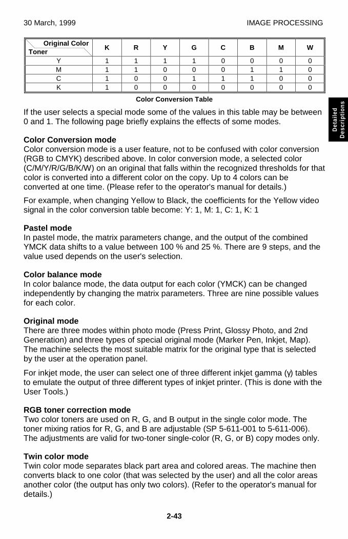
30 March, 1999 IMAGE PROCESSING
2-43
Det
aile
dD
escr
iptio
ns
Original ColorToner
K R Y G C B M W
Y 1 1 1 1 0 0 0 0M 1 1 0 0 0 1 1 0C 1 0 0 1 1 1 0 0K 1 0 0 0 0 0 0 0
Color Conversion Table
If the user selects a special mode some of the values in this table may be between0 and 1. The following page briefly explains the effects of some modes.
Color Conversion modeColor conversion mode is a user feature, not to be confused with color conversion(RGB to CMYK) described above. In color conversion mode, a selected color(C/M/Y/R/G/B/K/W) on an original that falls within the recognized thresholds for thatcolor is converted into a different color on the copy. Up to 4 colors can beconverted at one time. (Please refer to the operator's manual for details.)
For example, when changing Yellow to Black, the coefficients for the Yellow videosignal in the color conversion table become: Y: 1, M: 1, C: 1, K: 1
Pastel modeIn pastel mode, the matrix parameters change, and the output of the combinedYMCK data shifts to a value between 100 % and 25 %. There are 9 steps, and thevalue used depends on the user's selection.
Color balance modeIn color balance mode, the data output for each color (YMCK) can be changedindependently by changing the matrix parameters. Three are nine possible valuesfor each color.
Original modeThere are three modes within photo mode (Press Print, Glossy Photo, and 2ndGeneration) and three types of special original mode (Marker Pen, Inkjet, Map).The machine selects the most suitable matrix for the original type that is selectedby the user at the operation panel.
For inkjet mode, the user can select one of three different inkjet gamma (γ) tablesto emulate the output of three different types of inkjet printer. (This is done with theUser Tools.)
RGB toner correction modeTwo color toners are used on R, G, and B output in the single color mode. Thetoner mixing ratios for R, G, and B are adjustable (SP 5-611-001 to 5-611-006).The adjustments are valid for two-toner single-color (R, G, or B) copy modes only.
Twin color modeTwin color mode separates black part area and colored areas. The machine thenconverts black to one color (that was selected by the user) and all the color areasanother color (the output has only two colors). (Refer to the operator's manual fordetails.)
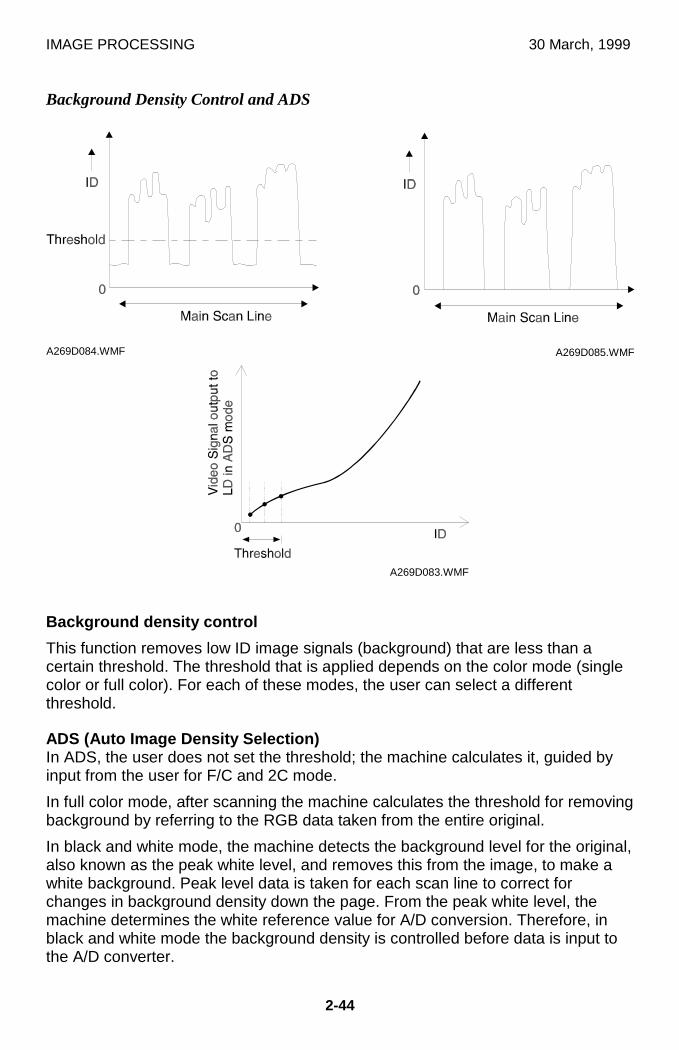
IMAGE PROCESSING 30 March, 1999
2-44
Background Density Control and ADS
Background density control
This function removes low ID image signals (background) that are less than acertain threshold. The threshold that is applied depends on the color mode (singlecolor or full color). For each of these modes, the user can select a differentthreshold.
ADS (Auto Image Density Selection)In ADS, the user does not set the threshold; the machine calculates it, guided byinput from the user for F/C and 2C mode.
In full color mode, after scanning the machine calculates the threshold for removingbackground by referring to the RGB data taken from the entire original.
In black and white mode, the machine detects the background level for the original,also known as the peak white level, and removes this from the image, to make awhite background. Peak level data is taken for each scan line to correct forchanges in background density down the page. From the peak white level, themachine determines the white reference value for A/D conversion. Therefore, inblack and white mode the background density is controlled before data is input tothe A/D converter.
A269D084.WMF A269D085.WMF
A269D083.WMF
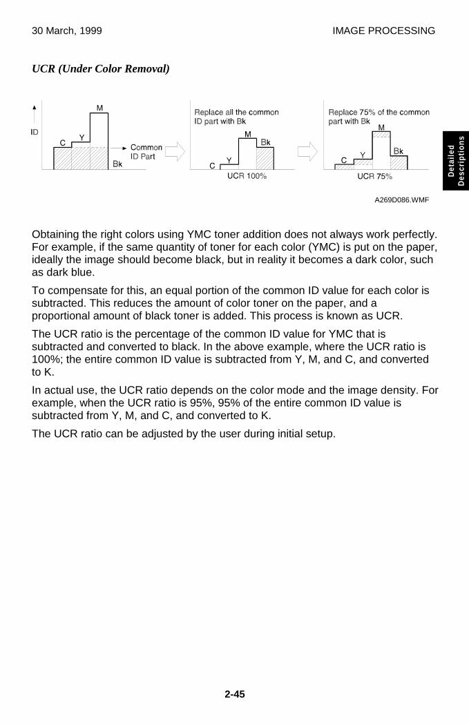
30 March, 1999 IMAGE PROCESSING
2-45
Det
aile
dD
escr
iptio
ns
UCR (Under Color Removal)
Obtaining the right colors using YMC toner addition does not always work perfectly.For example, if the same quantity of toner for each color (YMC) is put on the paper,ideally the image should become black, but in reality it becomes a dark color, suchas dark blue.
To compensate for this, an equal portion of the common ID value for each color issubtracted. This reduces the amount of color toner on the paper, and aproportional amount of black toner is added. This process is known as UCR.
The UCR ratio is the percentage of the common ID value for YMC that issubtracted and converted to black. In the above example, where the UCR ratio is100%; the entire common ID value is subtracted from Y, M, and C, and convertedto K.
In actual use, the UCR ratio depends on the color mode and the image density. Forexample, when the UCR ratio is 95%, 95% of the entire common ID value issubtracted from Y, M, and C, and converted to K.
The UCR ratio can be adjusted by the user during initial setup.
A269D086.WMF
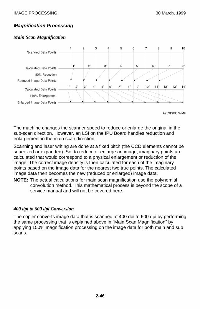
IMAGE PROCESSING 30 March, 1999
2-46
Magnification Processing
Main Scan Magnification
The machine changes the scanner speed to reduce or enlarge the original in thesub-scan direction. However, an LSI on the IPU Board handles reduction andenlargement in the main scan direction.
Scanning and laser writing are done at a fixed pitch (the CCD elements cannot besqueezed or expanded). So, to reduce or enlarge an image, imaginary points arecalculated that would correspond to a physical enlargement or reduction of theimage. The correct image density is then calculated for each of the imaginarypoints based on the image data for the nearest two true points. The calculatedimage data then becomes the new (reduced or enlarged) image data.NOTE: The actual calculations for main scan magnification use the polynomial
convolution method. This mathematical process is beyond the scope of aservice manual and will not be covered here.
400 dpi to 600 dpi Conversion
The copier converts image data that is scanned at 400 dpi to 600 dpi by performingthe same processing that is explained above in “Main Scan Magnification” byapplying 150% magnification processing on the image data for both main and subscans.
A269D088.WMF
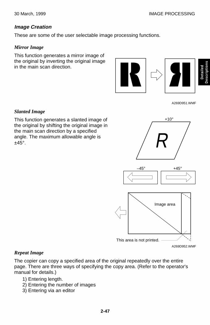
30 March, 1999 IMAGE PROCESSING
2-47
Det
aile
dD
escr
iptio
ns
Image Creation
These are some of the user selectable image processing functions.
Mirror Image
This function generates a mirror image ofthe original by inverting the original imagein the main scan direction.
Slanted Image
This function generates a slanted image ofthe original by shifting the original image inthe main scan direction by a specifiedangle. The maximum allowable angle is±45°.
Repeat Image
The copier can copy a specified area of the original repeatedly over the entirepage. There are three ways of specifying the copy area. (Refer to the operator'smanual for details.)
1) Entering length.2) Entering the number of images3) Entering via an editor
ûA269D951.WMF
��������������������������������������������������������
R
A269D952.WMF
Image area
This area is not printed.
+10°
–45° +45°
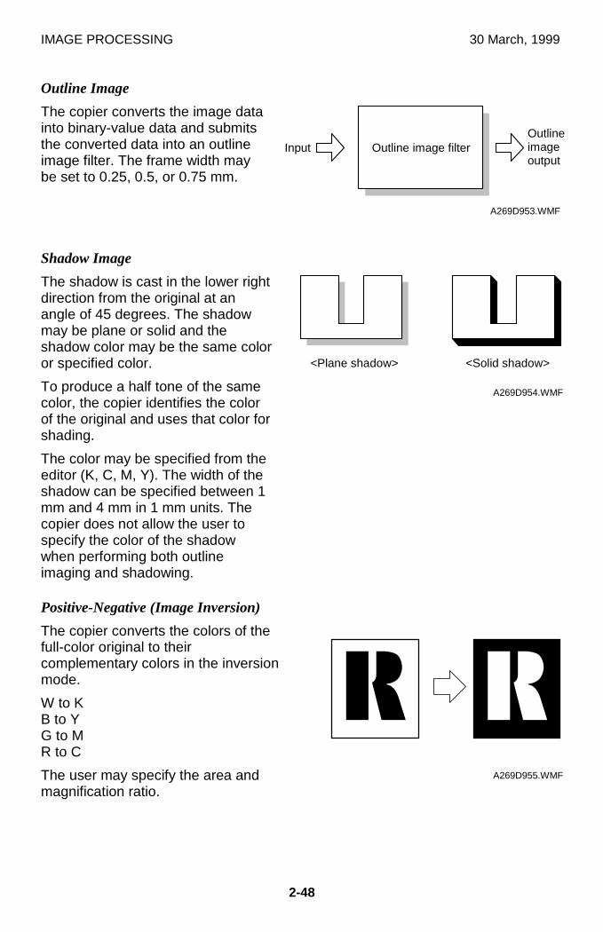
IMAGE PROCESSING 30 March, 1999
2-48
Outline Image
The copier converts the image datainto binary-value data and submitsthe converted data into an outlineimage filter. The frame width maybe set to 0.25, 0.5, or 0.75 mm.
Shadow Image
The shadow is cast in the lower rightdirection from the original at anangle of 45 degrees. The shadowmay be plane or solid and theshadow color may be the same coloror specified color.
To produce a half tone of the samecolor, the copier identifies the colorof the original and uses that color forshading.
The color may be specified from theeditor (K, C, M, Y). The width of theshadow can be specified between 1mm and 4 mm in 1 mm units. Thecopier does not allow the user tospecify the color of the shadowwhen performing both outlineimaging and shadowing.
Positive-Negative (Image Inversion)
The copier converts the colors of thefull-color original to theircomplementary colors in the inversionmode.
W to KB to YG to MR to C
The user may specify the area andmagnification ratio.
A269D953.WMF
������������������������������������������������������������������������������������������������������������������������������������������������������������������������������������������������������������������������������������������������������������������������������������������������������������
������������������������
A269D954.WMF
û ûA269D955.WMF
InputOutlineimageoutput
Outline image filter
<Plane shadow> <Solid shadow>
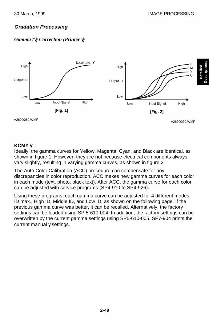
30 March, 1999 IMAGE PROCESSING
2-49
Det
aile
dD
escr
iptio
ns
Gradation Processing
Gamma (γγγγ) Correction (Printer γγγγ)
KCMY γγγγIdeally, the gamma curves for Yellow, Magenta, Cyan, and Black are identical, asshown in figure 1. However, they are not because electrical components alwaysvary slightly, resulting in varying gamma curves, as shown in figure 2.
The Auto Color Calibration (ACC) procedure can compensate for anydiscrepancies in color reproduction. ACC makes new gamma curves for each colorin each mode (text, photo, black text). After ACC, the gamma curve for each colorcan be adjusted with service programs (SP4-910 to SP4-926).
Using these programs, each gamma curve can be adjusted for 4 different modes:ID max., High ID, Middle ID, and Low ID, as shown on the following page. If theprevious gamma curve was better, it can be recalled. Alternatively, the factorysettings can be loaded using SP 5-610-004. In addition, the factory settings can beoverwritten by the current gamma settings using SP5-610-005. SP7-904 prints thecurrent manual γ settings.
K
A269D090.WMFA269D089.WMF
[Fig. 1] [Fig. 2]
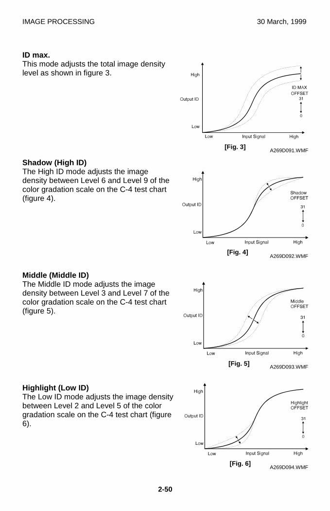
IMAGE PROCESSING 30 March, 1999
2-50
ID max.This mode adjusts the total image densitylevel as shown in figure 3.
Shadow (High ID)The High ID mode adjusts the imagedensity between Level 6 and Level 9 of thecolor gradation scale on the C-4 test chart(figure 4).
Middle (Middle ID)The Middle ID mode adjusts the imagedensity between Level 3 and Level 7 of thecolor gradation scale on the C-4 test chart(figure 5).
Highlight (Low ID)The Low ID mode adjusts the image densitybetween Level 2 and Level 5 of the colorgradation scale on the C-4 test chart (figure6).
A269D091.WMF
A269D092.WMF
A269D093.WMF
A269D094.WMF
[Fig. 3]
[Fig. 4]
[Fig. 5]
[Fig. 6]
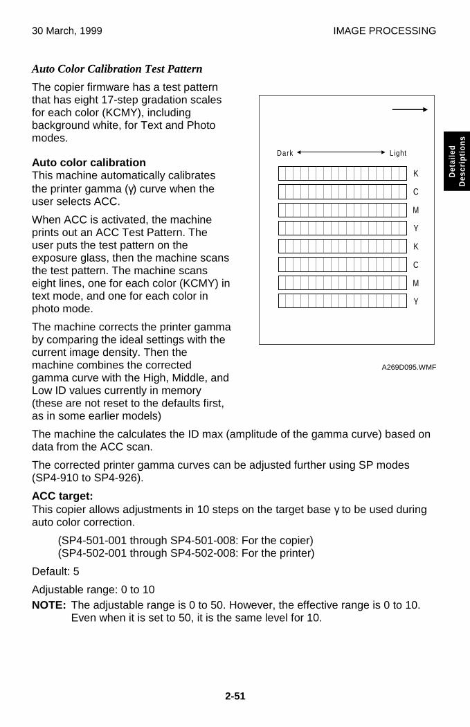
30 March, 1999 IMAGE PROCESSING
2-51
Det
aile
dD
escr
iptio
ns
Auto Color Calibration Test Pattern
The copier firmware has a test patternthat has eight 17-step gradation scalesfor each color (KCMY), includingbackground white, for Text and Photomodes.
Auto color calibrationThis machine automatically calibratesthe printer gamma (γ) curve when theuser selects ACC.
When ACC is activated, the machineprints out an ACC Test Pattern. Theuser puts the test pattern on theexposure glass, then the machine scansthe test pattern. The machine scanseight lines, one for each color (KCMY) intext mode, and one for each color inphoto mode.
The machine corrects the printer gammaby comparing the ideal settings with thecurrent image density. Then themachine combines the correctedgamma curve with the High, Middle, andLow ID values currently in memory(these are not reset to the defaults first,as in some earlier models)
The machine the calculates the ID max (amplitude of the gamma curve) based ondata from the ACC scan.
The corrected printer gamma curves can be adjusted further using SP modes(SP4-910 to SP4-926).
ACC target:This copier allows adjustments in 10 steps on the target base γ to be used duringauto color correction.
(SP4-501-001 through SP4-501-008: For the copier)(SP4-502-001 through SP4-502-008: For the printer)
Default: 5
Adjustable range: 0 to 10NOTE: The adjustable range is 0 to 50. However, the effective range is 0 to 10.
Even when it is set to 50, it is the same level for 10.
K
C
M
Y
K
C
M
Y
Dark Light
A269D095.WMF
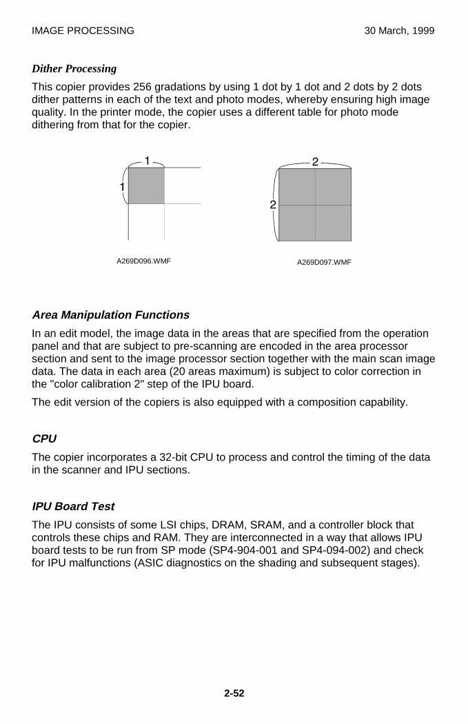
IMAGE PROCESSING 30 March, 1999
2-52
Dither Processing
This copier provides 256 gradations by using 1 dot by 1 dot and 2 dots by 2 dotsdither patterns in each of the text and photo modes, whereby ensuring high imagequality. In the printer mode, the copier uses a different table for photo modedithering from that for the copier.
Area Manipulation Functions
In an edit model, the image data in the areas that are specified from the operationpanel and that are subject to pre-scanning are encoded in the area processorsection and sent to the image processor section together with the main scan imagedata. The data in each area (20 areas maximum) is subject to color correction inthe "color calibration 2" step of the IPU board.
The edit version of the copiers is also equipped with a composition capability.
CPU
The copier incorporates a 32-bit CPU to process and control the timing of the datain the scanner and IPU sections.
IPU Board Test
The IPU consists of some LSI chips, DRAM, SRAM, and a controller block thatcontrols these chips and RAM. They are interconnected in a way that allows IPUboard tests to be run from SP mode (SP4-904-001 and SP4-094-002) and checkfor IPU malfunctions (ASIC diagnostics on the shading and subsequent stages).
A269D096.WMF A269D097.WMF
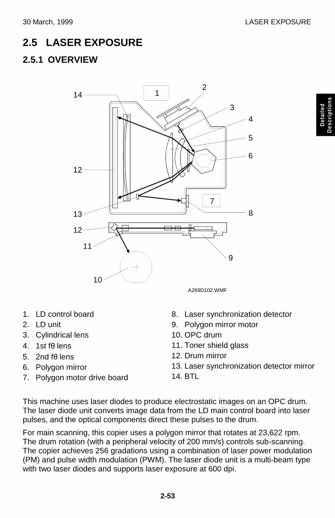
30 March, 1999 LASER EXPOSURE
2-53
Det
aile
dD
escr
iptio
ns
2.5 LASER EXPOSURE
2.5.1 OVERVIEW
1. LD control board2. LD unit3. Cylindrical lens4. 1st fθ lens5. 2nd fθ lens6. Polygon mirror7. Polygon motor drive board
8. Laser synchronization detector9. Polygon mirror motor10. OPC drum11. Toner shield glass12. Drum mirror13. Laser synchronization detector mirror14. BTL
This machine uses laser diodes to produce electrostatic images on an OPC drum.The laser diode unit converts image data from the LD main control board into laserpulses, and the optical components direct these pulses to the drum.
For main scanning, this copier uses a polygon mirror that rotates at 23,622 rpm.The drum rotation (with a peripheral velocity of 200 mm/s) controls sub-scanning.The copier achieves 256 gradations using a combination of laser power modulation(PM) and pulse width modulation (PWM). The laser diode unit is a multi-beam typewith two laser diodes and supports laser exposure at 600 dpi.
A269D102.WMF
3
12
4
5
6
7
8
9
10
11
12
13
12
14
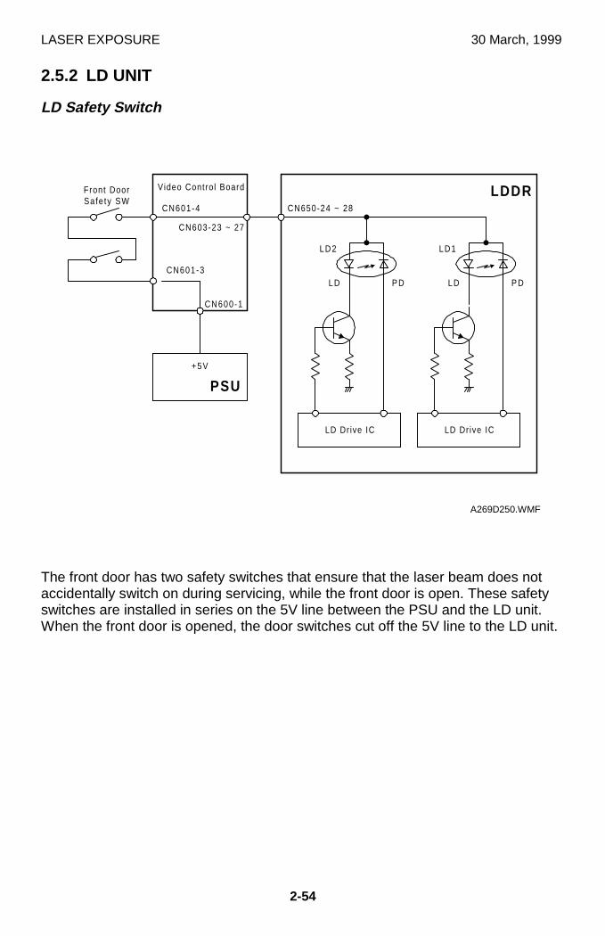
LASER EXPOSURE 30 March, 1999
2-54
2.5.2 LD UNIT
LD Safety Switch
The front door has two safety switches that ensure that the laser beam does notaccidentally switch on during servicing, while the front door is open. These safetyswitches are installed in series on the 5V line between the PSU and the LD unit.When the front door is opened, the door switches cut off the 5V line to the LD unit.
LDDRCN601-4
LD Dr ive ICLD Dr ive IC
CN603-23 ~ 27
CN650-24 ~ 28
LD2 LD1
LD LDP D P D
+5V
CN601-3
CN600-1
Front DoorSafe ty SW
PSU
Video Control Board
A269D250.WMF
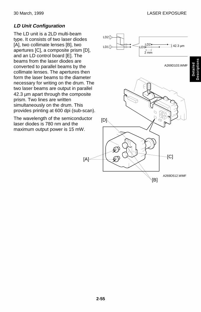
30 March, 1999 LASER EXPOSURE
2-55
Det
aile
dD
escr
iptio
ns
LD Unit Configuration
The LD unit is a 2LD multi-beamtype. It consists of two laser diodes[A], two collimate lenses [B], twoapertures [C], a composite prism [D],and an LD control board [E]. Thebeams from the laser diodes areconverted to parallel beams by thecollimate lenses. The apertures thenform the laser beams to the diameternecessary for writing on the drum. Thetwo laser beams are output in parallel42.3 µm apart through the compositeprism. Two lines are writtensimultaneously on the drum. Thisprovides printing at 600 dpi (sub-scan).
The wavelength of the semiconductorlaser diodes is 780 nm and themaximum output power is 15 mW.
A269D103.WMF
A269D512.WMF
LD1LD2
2 mm
42.3 µm
LD2
LD1
[A]
[B]
[C]
[D]
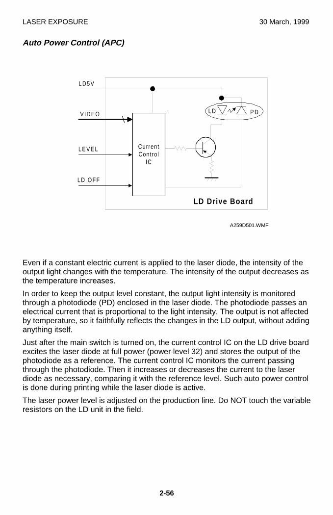
LASER EXPOSURE 30 March, 1999
2-56
Auto Power Control (APC)
Even if a constant electric current is applied to the laser diode, the intensity of theoutput light changes with the temperature. The intensity of the output decreases asthe temperature increases.
In order to keep the output level constant, the output light intensity is monitoredthrough a photodiode (PD) enclosed in the laser diode. The photodiode passes anelectrical current that is proportional to the light intensity. The output is not affectedby temperature, so it faithfully reflects the changes in the LD output, without addinganything itself.
Just after the main switch is turned on, the current control IC on the LD drive boardexcites the laser diode at full power (power level 32) and stores the output of thephotodiode as a reference. The current control IC monitors the current passingthrough the photodiode. Then it increases or decreases the current to the laserdiode as necessary, comparing it with the reference level. Such auto power controlis done during printing while the laser diode is active.
The laser power level is adjusted on the production line. Do NOT touch the variableresistors on the LD unit in the field.
CurrentContro l
IC
L D 5 V
L D P D
LD Drive Board
V I D E O
L E V E L
LD OFF
A259D501.WMF
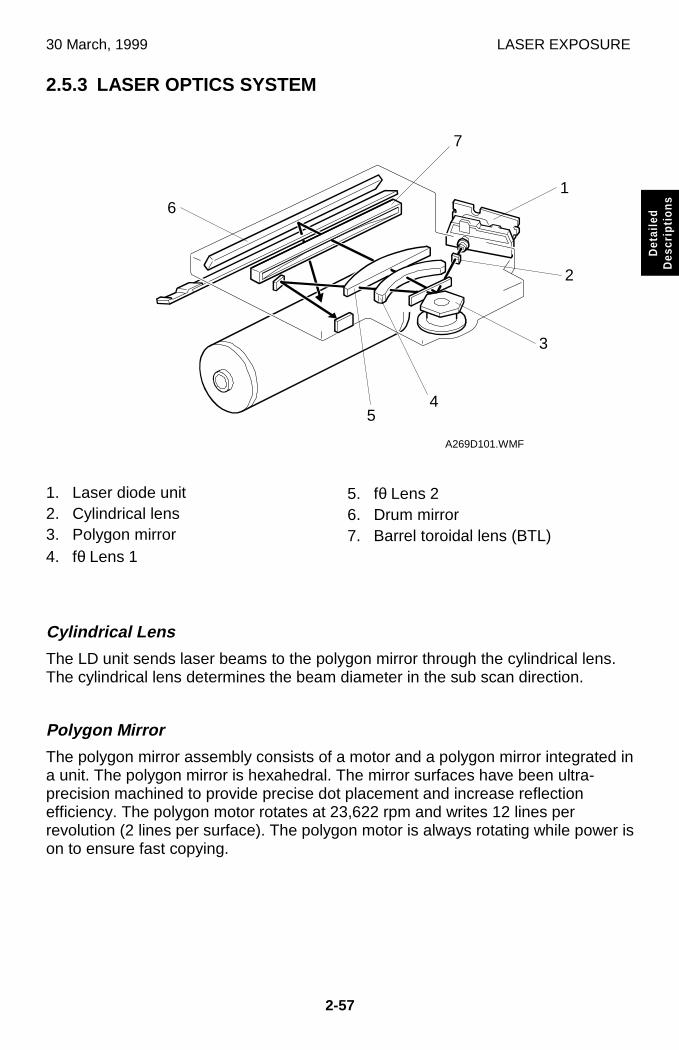
30 March, 1999 LASER EXPOSURE
2-57
Det
aile
dD
escr
iptio
ns
2.5.3 LASER OPTICS SYSTEM
1. Laser diode unit2. Cylindrical lens3. Polygon mirror4. fθ Lens 1
5. fθ Lens 26. Drum mirror7. Barrel toroidal lens (BTL)
Cylindrical Lens
The LD unit sends laser beams to the polygon mirror through the cylindrical lens.The cylindrical lens determines the beam diameter in the sub scan direction.
Polygon Mirror
The polygon mirror assembly consists of a motor and a polygon mirror integrated ina unit. The polygon mirror is hexahedral. The mirror surfaces have been ultra-precision machined to provide precise dot placement and increase reflectionefficiency. The polygon motor rotates at 23,622 rpm and writes 12 lines perrevolution (2 lines per surface). The polygon motor is always rotating while power ison to ensure fast copying.
A269D101.WMF
1
2
3
45
6
7
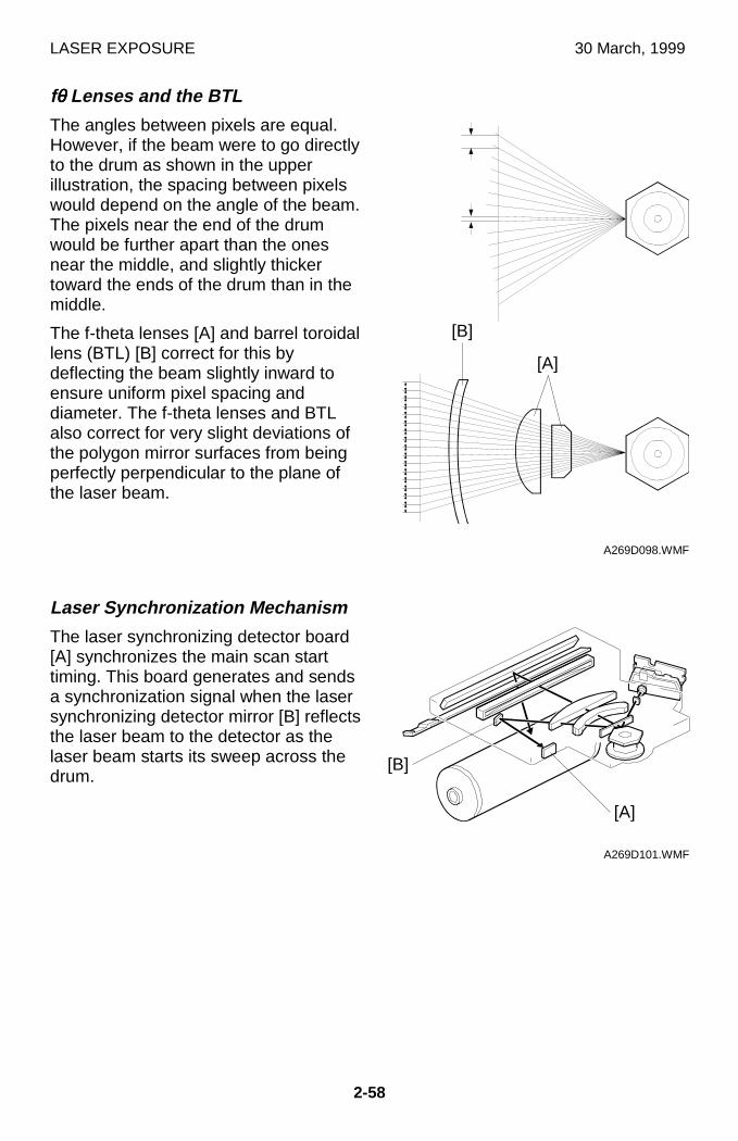
LASER EXPOSURE 30 March, 1999
2-58
fθθθθ Lenses and the BTL
The angles between pixels are equal.However, if the beam were to go directlyto the drum as shown in the upperillustration, the spacing between pixelswould depend on the angle of the beam.The pixels near the end of the drumwould be further apart than the onesnear the middle, and slightly thickertoward the ends of the drum than in themiddle.
The f-theta lenses [A] and barrel toroidallens (BTL) [B] correct for this bydeflecting the beam slightly inward toensure uniform pixel spacing anddiameter. The f-theta lenses and BTLalso correct for very slight deviations ofthe polygon mirror surfaces from beingperfectly perpendicular to the plane ofthe laser beam.
Laser Synchronization Mechanism
The laser synchronizing detector board[A] synchronizes the main scan starttiming. This board generates and sendsa synchronization signal when the lasersynchronizing detector mirror [B] reflectsthe laser beam to the detector as thelaser beam starts its sweep across thedrum.
A269D098.WMF
A269D101.WMF
[A]
[A]
[B]
[B]
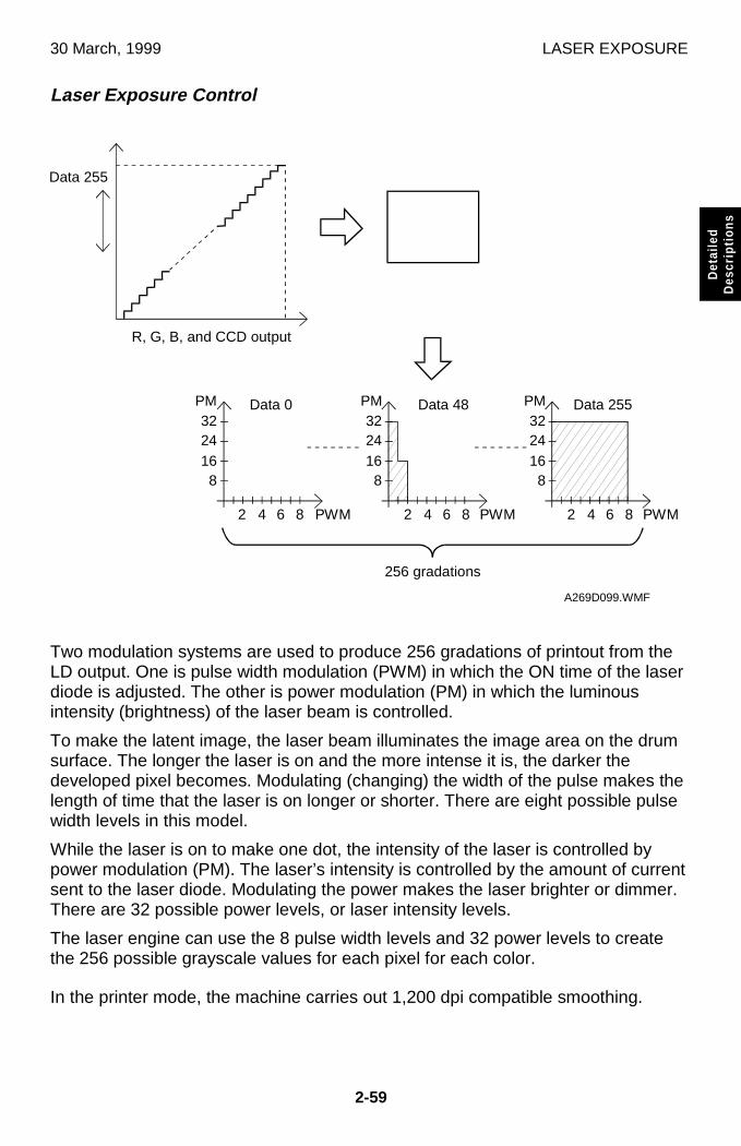
30 March, 1999 LASER EXPOSURE
2-59
Det
aile
dD
escr
iptio
ns
Laser Exposure Control
Two modulation systems are used to produce 256 gradations of printout from theLD output. One is pulse width modulation (PWM) in which the ON time of the laserdiode is adjusted. The other is power modulation (PM) in which the luminousintensity (brightness) of the laser beam is controlled.
To make the latent image, the laser beam illuminates the image area on the drumsurface. The longer the laser is on and the more intense it is, the darker thedeveloped pixel becomes. Modulating (changing) the width of the pulse makes thelength of time that the laser is on longer or shorter. There are eight possible pulsewidth levels in this model.
While the laser is on to make one dot, the intensity of the laser is controlled bypower modulation (PM). The laser’s intensity is controlled by the amount of currentsent to the laser diode. Modulating the power makes the laser brighter or dimmer.There are 32 possible power levels, or laser intensity levels.
The laser engine can use the 8 pulse width levels and 32 power levels to createthe 256 possible grayscale values for each pixel for each color.
In the printer mode, the machine carries out 1,200 dpi compatible smoothing.
A269D099.WMF
Data 255
R, G, B, and CCD output
8162432
8162432
8162432
PM PM PM
2 4 6 8 PWM 2 4 6 8 PWM 2 4 6 8 PWM
Data 0 Data 48 Data 255
256 gradations
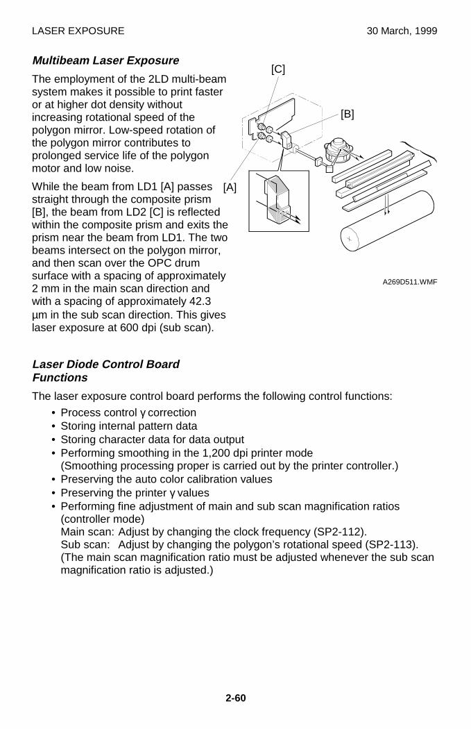
LASER EXPOSURE 30 March, 1999
2-60
Multibeam Laser Exposure
The employment of the 2LD multi-beamsystem makes it possible to print fasteror at higher dot density withoutincreasing rotational speed of thepolygon mirror. Low-speed rotation ofthe polygon mirror contributes toprolonged service life of the polygonmotor and low noise.
While the beam from LD1 [A] passesstraight through the composite prism[B], the beam from LD2 [C] is reflectedwithin the composite prism and exits theprism near the beam from LD1. The twobeams intersect on the polygon mirror,and then scan over the OPC drumsurface with a spacing of approximately2 mm in the main scan direction andwith a spacing of approximately 42.3µm in the sub scan direction. This giveslaser exposure at 600 dpi (sub scan).
Laser Diode Control BoardFunctions
The laser exposure control board performs the following control functions:
• Process control γ correction• Storing internal pattern data• Storing character data for data output• Performing smoothing in the 1,200 dpi printer mode
(Smoothing processing proper is carried out by the printer controller.)• Preserving the auto color calibration values• Preserving the printer γ values• Performing fine adjustment of main and sub scan magnification ratios
(controller mode)Main scan: Adjust by changing the clock frequency (SP2-112).Sub scan: Adjust by changing the polygon’s rotational speed (SP2-113).(The main scan magnification ratio must be adjusted whenever the sub scanmagnification ratio is adjusted.)
A269D511.WMF
[B]
[A]
[C]
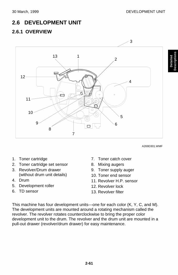
30 March, 1999 DEVELOPMENT UNIT
2-61
Det
aile
dD
escr
iptio
ns
2.6 DEVELOPMENT UNIT
2.6.1 OVERVIEW
1. Toner cartridge2. Toner cartridge set sensor3. Revolver/Drum drawer
(without drum unit details)4. Drum5. Development roller6. TD sensor
7. Toner catch cover8. Mixing augers9. Toner supply auger10. Toner end sensor11. Revolver H.P. sensor12. Revolver lock13. Revolver filter
This machine has four development units—one for each color (K, Y, C, and M).The development units are mounted around a rotating mechanism called therevolver. The revolver rotates counterclockwise to bring the proper colordevelopment unit to the drum. The revolver and the drum unit are mounted in apull-out drawer (revolver/drum drawer) for easy maintenance.
A269D301.WMF
3
4
12
5
6
7
11
12
10
98
13
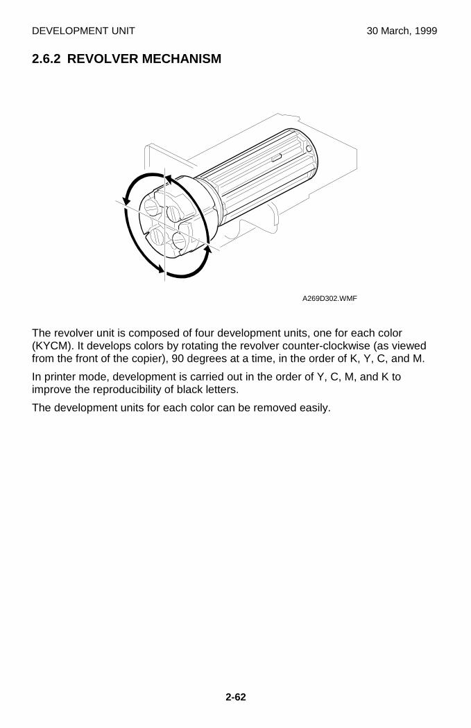
DEVELOPMENT UNIT 30 March, 1999
2-62
2.6.2 REVOLVER MECHANISM
The revolver unit is composed of four development units, one for each color(KYCM). It develops colors by rotating the revolver counter-clockwise (as viewedfrom the front of the copier), 90 degrees at a time, in the order of K, Y, C, and M.
In printer mode, development is carried out in the order of Y, C, M, and K toimprove the reproducibility of black letters.
The development units for each color can be removed easily.
A269D302.WMF
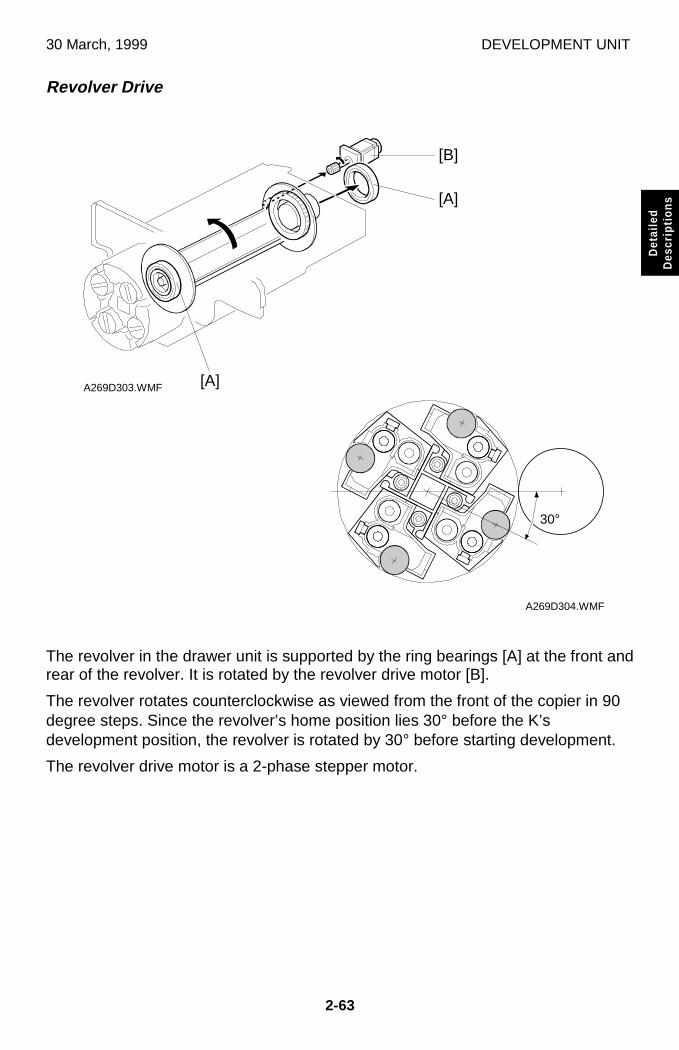
30 March, 1999 DEVELOPMENT UNIT
2-63
Det
aile
dD
escr
iptio
ns
Revolver Drive
The revolver in the drawer unit is supported by the ring bearings [A] at the front andrear of the revolver. It is rotated by the revolver drive motor [B].
The revolver rotates counterclockwise as viewed from the front of the copier in 90degree steps. Since the revolver’s home position lies 30° before the K’sdevelopment position, the revolver is rotated by 30° before starting development.
The revolver drive motor is a 2-phase stepper motor.
A269D304.WMF
A269D303.WMF [A]
[B]
[A]
30°
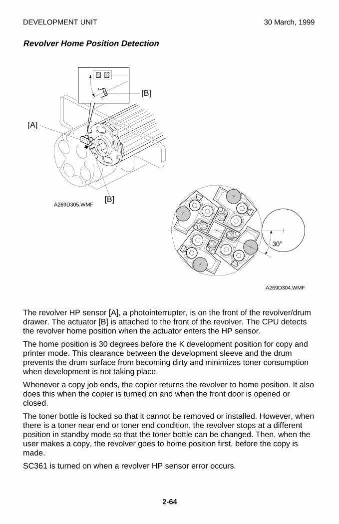
DEVELOPMENT UNIT 30 March, 1999
2-64
Revolver Home Position Detection
The revolver HP sensor [A], a photointerrupter, is on the front of the revolver/drumdrawer. The actuator [B] is attached to the front of the revolver. The CPU detectsthe revolver home position when the actuator enters the HP sensor.
The home position is 30 degrees before the K development position for copy andprinter mode. This clearance between the development sleeve and the drumprevents the drum surface from becoming dirty and minimizes toner consumptionwhen development is not taking place.
Whenever a copy job ends, the copier returns the revolver to home position. It alsodoes this when the copier is turned on and when the front door is opened orclosed.
The toner bottle is locked so that it cannot be removed or installed. However, whenthere is a toner near end or toner end condition, the revolver stops at a differentposition in standby mode so that the toner bottle can be changed. Then, when theuser makes a copy, the revolver goes to home position first, before the copy ismade.
SC361 is turned on when a revolver HP sensor error occurs.
A269D305.WMF
A269D304.WMF
[B]
[B]
[A]
30°
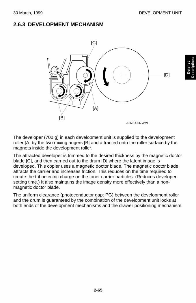
30 March, 1999 DEVELOPMENT UNIT
2-65
Det
aile
dD
escr
iptio
ns
2.6.3 DEVELOPMENT MECHANISM
The developer (700 g) in each development unit is supplied to the developmentroller [A] by the two mixing augers [B] and attracted onto the roller surface by themagnets inside the development roller.
The attracted developer is trimmed to the desired thickness by the magnetic doctorblade [C], and then carried out to the drum [D] where the latent image isdeveloped. This copier uses a magnetic doctor blade. The magnetic doctor bladeattracts the carrier and increases friction. This reduces on the time required tocreate the triboelectric charge on the toner carrier particles. (Reduces developersetting time.) It also maintains the image density more effectively than a non-magnetic doctor blade.
The uniform clearance (photoconductor gap: PG) between the development rollerand the drum is guaranteed by the combination of the development unit locks atboth ends of the development mechanisms and the drawer positioning mechanism.
A269D306.WMF
[B]
[D]
[C]
[A]
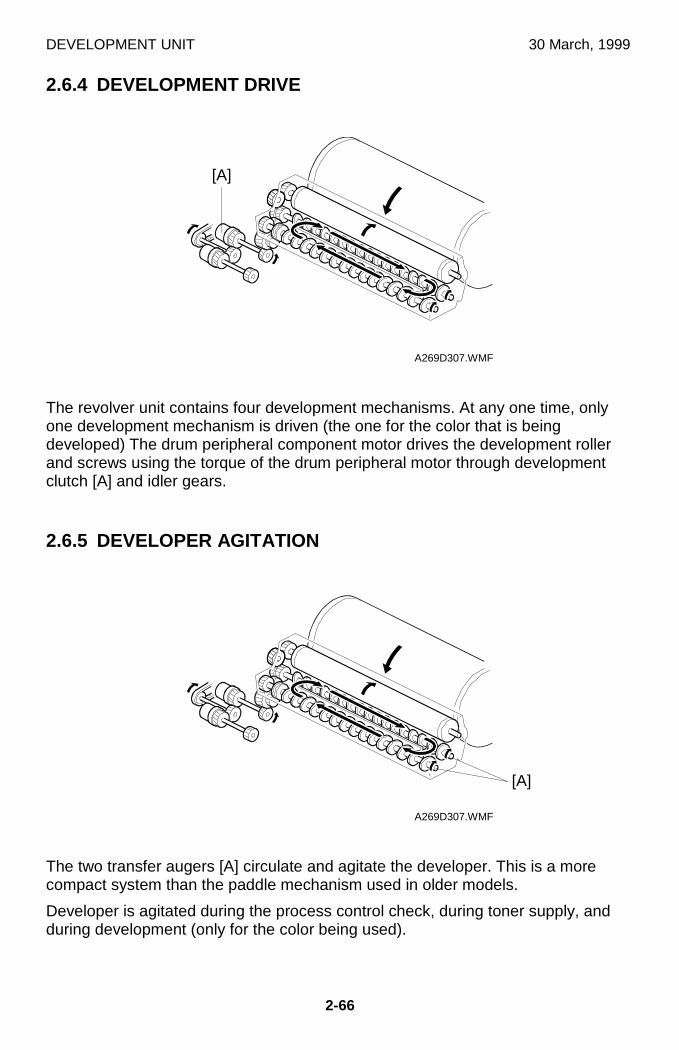
DEVELOPMENT UNIT 30 March, 1999
2-66
2.6.4 DEVELOPMENT DRIVE
The revolver unit contains four development mechanisms. At any one time, onlyone development mechanism is driven (the one for the color that is beingdeveloped) The drum peripheral component motor drives the development rollerand screws using the torque of the drum peripheral motor through developmentclutch [A] and idler gears.
2.6.5 DEVELOPER AGITATION
The two transfer augers [A] circulate and agitate the developer. This is a morecompact system than the paddle mechanism used in older models.
Developer is agitated during the process control check, during toner supply, andduring development (only for the color being used).
A269D307.WMF
A269D307.WMF
[A]
[A]
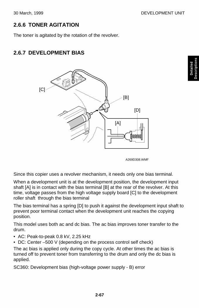
30 March, 1999 DEVELOPMENT UNIT
2-67
Det
aile
dD
escr
iptio
ns
2.6.6 TONER AGITATION
The toner is agitated by the rotation of the revolver.
2.6.7 DEVELOPMENT BIAS
Since this copier uses a revolver mechanism, it needs only one bias terminal.
When a development unit is at the development position, the development inputshaft [A] is in contact with the bias terminal [B] at the rear of the revolver. At thistime, voltage passes from the high voltage supply board [C] to the developmentroller shaft through the bias terminal
The bias terminal has a spring [D] to push it against the development input shaft toprevent poor terminal contact when the development unit reaches the copyingposition.
This model uses both ac and dc bias. The ac bias improves toner transfer to thedrum.
• AC: Peak-to-peak 0.8 kV, 2.25 kHz• DC: Center –500 V (depending on the process control self check)The ac bias is applied only during the copy cycle. At other times the ac bias isturned off to prevent toner from transferring to the drum and only the dc bias isapplied.
SC360: Development bias (high-voltage power supply - B) error
A269D308.WMF
[A]
[C]
[D]
[B]
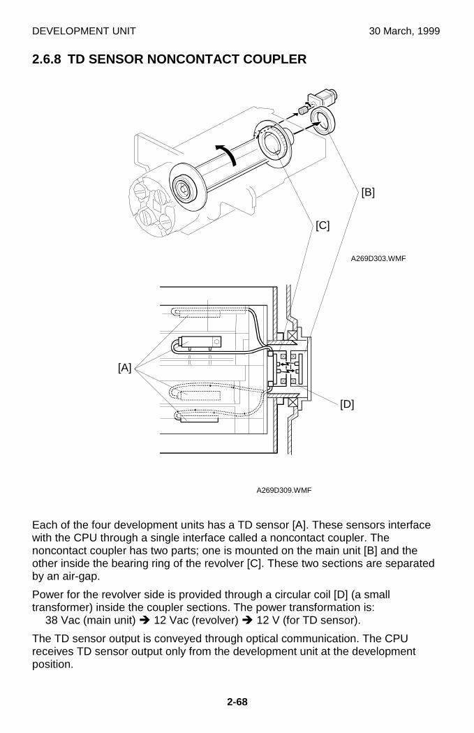
DEVELOPMENT UNIT 30 March, 1999
2-68
2.6.8 TD SENSOR NONCONTACT COUPLER
Each of the four development units has a TD sensor [A]. These sensors interfacewith the CPU through a single interface called a noncontact coupler. Thenoncontact coupler has two parts; one is mounted on the main unit [B] and theother inside the bearing ring of the revolver [C]. These two sections are separatedby an air-gap.
Power for the revolver side is provided through a circular coil [D] (a smalltransformer) inside the coupler sections. The power transformation is:
38 Vac (main unit) Î 12 Vac (revolver) Î 12 V (for TD sensor).
The TD sensor output is conveyed through optical communication. The CPUreceives TD sensor output only from the development unit at the developmentposition.
A269D303.WMF
A269D309.WMF
[C]
[B]
[A]
[D]
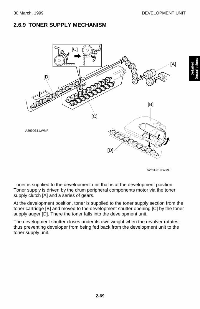
30 March, 1999 DEVELOPMENT UNIT
2-69
Det
aile
dD
escr
iptio
ns
2.6.9 TONER SUPPLY MECHANISM
Toner is supplied to the development unit that is at the development position.Toner supply is driven by the drum peripheral components motor via the tonersupply clutch [A] and a series of gears.
At the development position, toner is supplied to the toner supply section from thetoner cartridge [B] and moved to the development shutter opening [C] by the tonersupply auger [D]. There the toner falls into the development unit.
The development shutter closes under its own weight when the revolver rotates,thus preventing developer from being fed back from the development unit to thetoner supply unit.
A269D311.WMF
A269D310.WMF
[D]
[A]
[B]
[D]
[C]
[C]
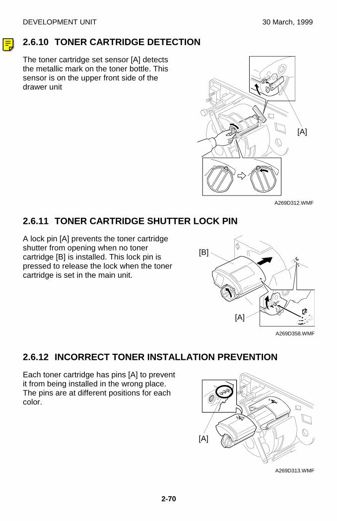
DEVELOPMENT UNIT 30 March, 1999
2-70
2.6.10 TONER CARTRIDGE DETECTION
The toner cartridge set sensor [A] detectsthe metallic mark on the toner bottle. Thissensor is on the upper front side of thedrawer unit
2.6.11 TONER CARTRIDGE SHUTTER LOCK PIN
A lock pin [A] prevents the toner cartridgeshutter from opening when no tonercartridge [B] is installed. This lock pin ispressed to release the lock when the tonercartridge is set in the main unit.
2.6.12 INCORRECT TONER INSTALLATION PREVENTION
Each toner cartridge has pins [A] to preventit from being installed in the wrong place.The pins are at different positions for eachcolor.
A269D312.WMF
A269D358.WMF
A269D313.WMF
[A]
[A]
[B]
[A]
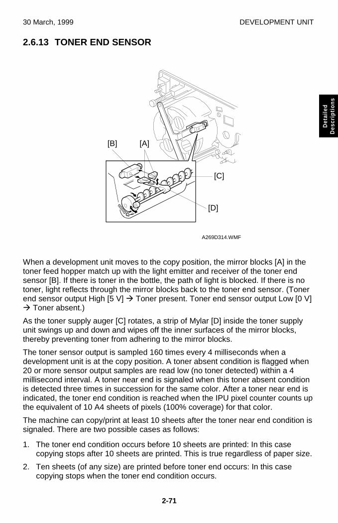
30 March, 1999 DEVELOPMENT UNIT
2-71
Det
aile
dD
escr
iptio
ns
2.6.13 TONER END SENSOR
When a development unit moves to the copy position, the mirror blocks [A] in thetoner feed hopper match up with the light emitter and receiver of the toner endsensor [B]. If there is toner in the bottle, the path of light is blocked. If there is notoner, light reflects through the mirror blocks back to the toner end sensor. (Tonerend sensor output High [5 V] Æ Toner present. Toner end sensor output Low [0 V]Æ Toner absent.)
As the toner supply auger [C] rotates, a strip of Mylar [D] inside the toner supplyunit swings up and down and wipes off the inner surfaces of the mirror blocks,thereby preventing toner from adhering to the mirror blocks.
The toner sensor output is sampled 160 times every 4 milliseconds when adevelopment unit is at the copy position. A toner absent condition is flagged when20 or more sensor output samples are read low (no toner detected) within a 4millisecond interval. A toner near end is signaled when this toner absent conditionis detected three times in succession for the same color. After a toner near end isindicated, the toner end condition is reached when the IPU pixel counter counts upthe equivalent of 10 A4 sheets of pixels (100% coverage) for that color.
The machine can copy/print at least 10 sheets after the toner near end condition issignaled. There are two possible cases as follows:
1. The toner end condition occurs before 10 sheets are printed: In this casecopying stops after 10 sheets are printed. This is true regardless of paper size.
2. Ten sheets (of any size) are printed before toner end occurs: In this casecopying stops when the toner end condition occurs.
A269D314.WMF
[A]
[C]
[D]
[B]
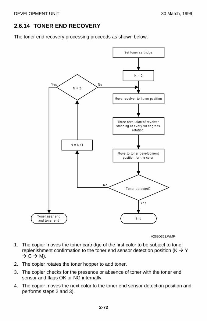
DEVELOPMENT UNIT 30 March, 1999
2-72
2.6.14 TONER END RECOVERY
The toner end recovery processing proceeds as shown below.
1. The copier moves the toner cartridge of the first color to be subject to tonerreplenishment confirmation to the toner end sensor detection position (K Æ YÆ C Æ M).
2. The copier rotates the toner hopper to add toner.
3. The copier checks for the presence or absence of toner with the toner endsensor and flags OK or NG internally.
4. The copier moves the next color to the toner end sensor detection position andperforms steps 2 and 3).
No
End
Yes
Set toner cartr idge
N = 0
Move revolver to home posit ion
Move to toner developmentposit ion for the color
Toner detected?
N = 2
N = N+1
No
Yes
Toner near endand toner end
Three revolut ion of revolverstopping at every 90 degrees
rotation.
A269D351.WMF

30 March, 1999 DEVELOPMENT UNIT
2-73
Det
aile
dD
escr
iptio
ns
5. When the toner recovery cycle ends, the copier moves the revolver to the tonerend sensor detection position for any cartridges that are still flagged as NG. Itthen performs the toner recovery cycle again. If a cartridge is flagged NGagain, the copier returns the cartridge to the state before the toner recoverystate (toner near end and toner end LEDs are lit).
6. The copier resets the toner near end and toner end states and resets the tonerend related counters (pixel and page counters) for toners for which tonerrecovery was completed and flagged OK.
2.6.15 TONER LOOSENING
This copier loosens the toner in the toner cartridge by rotating the revolver 3 turnsbefore performing the auto initial process control self check at power-on time. Thisprevents the toner inside the cartridge from adhering together and forming lumps oftoner when the copier is not in use for a long time.
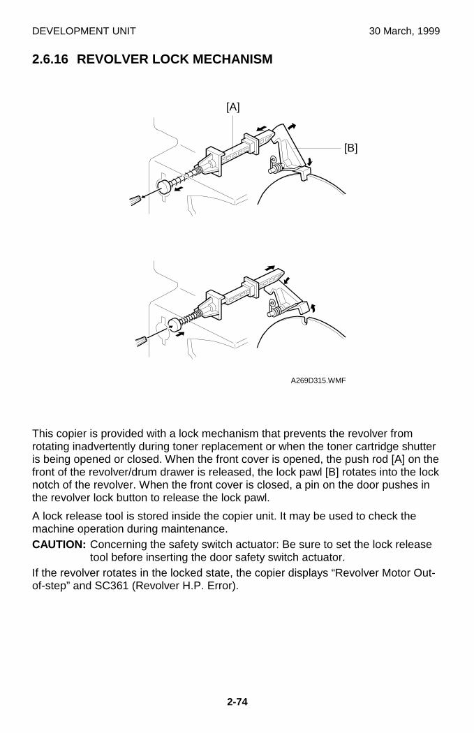
DEVELOPMENT UNIT 30 March, 1999
2-74
2.6.16 REVOLVER LOCK MECHANISM
This copier is provided with a lock mechanism that prevents the revolver fromrotating inadvertently during toner replacement or when the toner cartridge shutteris being opened or closed. When the front cover is opened, the push rod [A] on thefront of the revolver/drum drawer is released, the lock pawl [B] rotates into the locknotch of the revolver. When the front cover is closed, a pin on the door pushes inthe revolver lock button to release the lock pawl.
A lock release tool is stored inside the copier unit. It may be used to check themachine operation during maintenance.CAUTION: Concerning the safety switch actuator: Be sure to set the lock release
tool before inserting the door safety switch actuator.If the revolver rotates in the locked state, the copier displays “Revolver Motor Out-of-step” and SC361 (Revolver H.P. Error).
A269D315.WMF
[A]
[B]
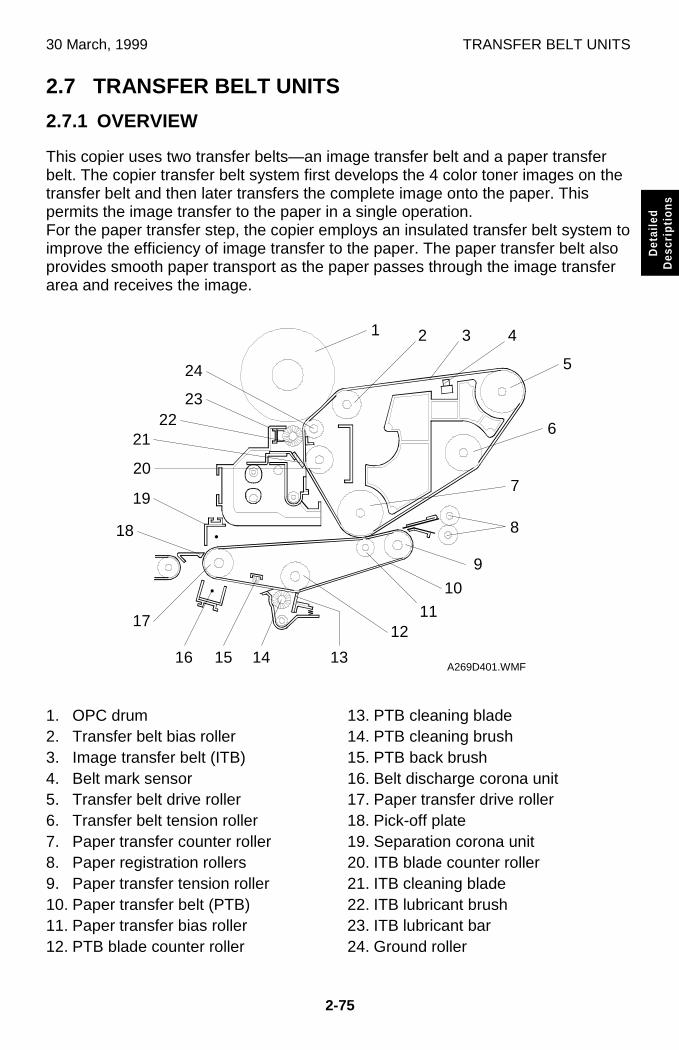
30 March, 1999 TRANSFER BELT UNITS
2-75
Det
aile
dD
escr
iptio
ns
2.7 TRANSFER BELT UNITS
2.7.1 OVERVIEW
This copier uses two transfer belts—an image transfer belt and a paper transferbelt. The copier transfer belt system first develops the 4 color toner images on thetransfer belt and then later transfers the complete image onto the paper. Thispermits the image transfer to the paper in a single operation.For the paper transfer step, the copier employs an insulated transfer belt system toimprove the efficiency of image transfer to the paper. The paper transfer belt alsoprovides smooth paper transport as the paper passes through the image transferarea and receives the image.
1. OPC drum2. Transfer belt bias roller3. Image transfer belt (ITB)4. Belt mark sensor5. Transfer belt drive roller6. Transfer belt tension roller7. Paper transfer counter roller8. Paper registration rollers9. Paper transfer tension roller10. Paper transfer belt (PTB)11. Paper transfer bias roller12. PTB blade counter roller
13. PTB cleaning blade14. PTB cleaning brush15. PTB back brush16. Belt discharge corona unit17. Paper transfer drive roller18. Pick-off plate19. Separation corona unit20. ITB blade counter roller21. ITB cleaning blade22. ITB lubricant brush23. ITB lubricant bar24. Ground roller
A269D401.WMF
8
5
6
7
9
10
1112
13141516
17
18
19
20
2122
23
24
1 2 3 4
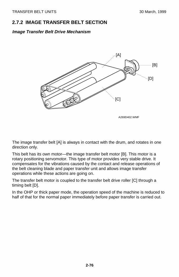
TRANSFER BELT UNITS 30 March, 1999
2-76
2.7.2 IMAGE TRANSFER BELT SECTION
Image Transfer Belt Drive Mechanism
The image transfer belt [A] is always in contact with the drum, and rotates in onedirection only.
This belt has its own motor—the image transfer belt motor [B]. This motor is arotary positioning servomotor. This type of motor provides very stable drive. Itcompensates for the vibrations caused by the contact and release operations ofthe belt cleaning blade and paper transfer unit and allows image transferoperations while these actions are going on.
The transfer belt motor is coupled to the transfer belt drive roller [C] through atiming belt [D].
In the OHP or thick paper mode, the operation speed of the machine is reduced tohalf of that for the normal paper immediately before paper transfer is carried out.
A269D402.WMF
[A]
[B]
[C]
[D]
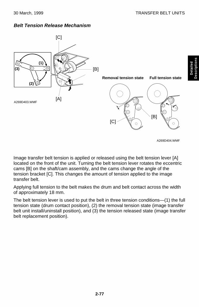
30 March, 1999 TRANSFER BELT UNITS
2-77
Det
aile
dD
escr
iptio
ns
Belt Tension Release Mechanism
Image transfer belt tension is applied or released using the belt tension lever [A]located on the front of the unit. Turning the belt tension lever rotates the eccentriccams [B] on the shaft/cam assembly, and the cams change the angle of thetension bracket [C]. This changes the amount of tension applied to the imagetransfer belt.
Applying full tension to the belt makes the drum and belt contact across the widthof approximately 18 mm.
The belt tension lever is used to put the belt in three tension conditions—(1) the fulltension state (drum contact position), (2) the removal tension state (image transferbelt unit install/uninstall position), and (3) the tension released state (image transferbelt replacement position).
A269D403.WMF
A269D404.WMF
(1)
(2)
(3)
[C]
[B]
[A]
Removal tension state Full tension state
[C][B]
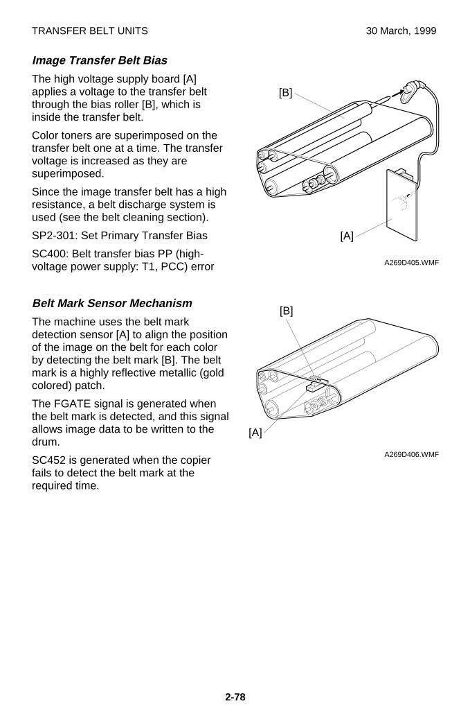
TRANSFER BELT UNITS 30 March, 1999
2-78
Image Transfer Belt Bias
The high voltage supply board [A]applies a voltage to the transfer beltthrough the bias roller [B], which isinside the transfer belt.
Color toners are superimposed on thetransfer belt one at a time. The transfervoltage is increased as they aresuperimposed.
Since the image transfer belt has a highresistance, a belt discharge system isused (see the belt cleaning section).
SP2-301: Set Primary Transfer Bias
SC400: Belt transfer bias PP (high-voltage power supply: T1, PCC) error
Belt Mark Sensor Mechanism
The machine uses the belt markdetection sensor [A] to align the positionof the image on the belt for each colorby detecting the belt mark [B]. The beltmark is a highly reflective metallic (goldcolored) patch.
The FGATE signal is generated whenthe belt mark is detected, and this signalallows image data to be written to thedrum.
SC452 is generated when the copierfails to detect the belt mark at therequired time.
A269D405.WMF
A269D406.WMF
[A]
[B]
[A]
[B]
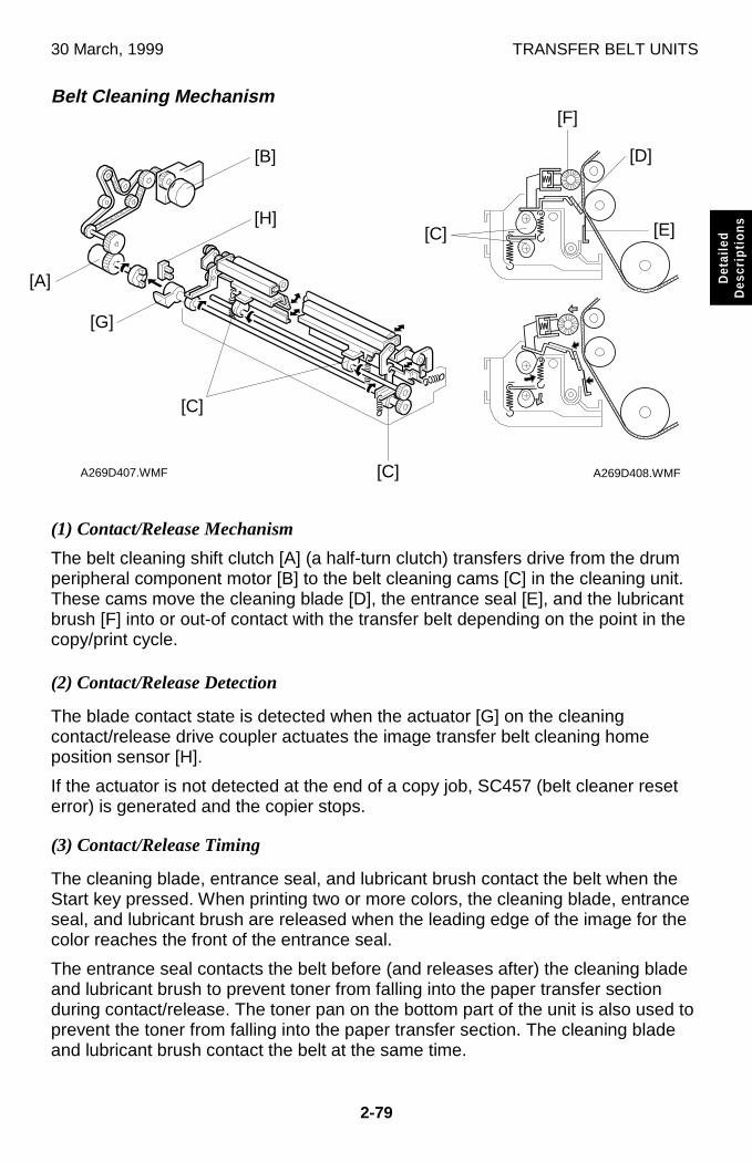
30 March, 1999 TRANSFER BELT UNITS
2-79
Det
aile
dD
escr
iptio
ns
Belt Cleaning Mechanism
(1) Contact/Release Mechanism
The belt cleaning shift clutch [A] (a half-turn clutch) transfers drive from the drumperipheral component motor [B] to the belt cleaning cams [C] in the cleaning unit.These cams move the cleaning blade [D], the entrance seal [E], and the lubricantbrush [F] into or out-of contact with the transfer belt depending on the point in thecopy/print cycle.
(2) Contact/Release Detection
The blade contact state is detected when the actuator [G] on the cleaningcontact/release drive coupler actuates the image transfer belt cleaning homeposition sensor [H].
If the actuator is not detected at the end of a copy job, SC457 (belt cleaner reseterror) is generated and the copier stops.
(3) Contact/Release Timing
The cleaning blade, entrance seal, and lubricant brush contact the belt when theStart key pressed. When printing two or more colors, the cleaning blade, entranceseal, and lubricant brush are released when the leading edge of the image for thecolor reaches the front of the entrance seal.
The entrance seal contacts the belt before (and releases after) the cleaning bladeand lubricant brush to prevent toner from falling into the paper transfer sectionduring contact/release. The toner pan on the bottom part of the unit is also used toprevent the toner from falling into the paper transfer section. The cleaning bladeand lubricant brush contact the belt at the same time.
A269D408.WMFA269D407.WMF [C]
[E]
[F]
[H]
[B]
[G]
[C]
[D]
[C]
[A]
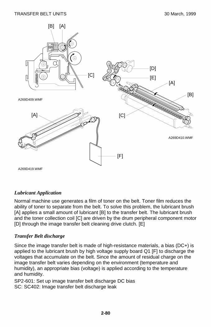
TRANSFER BELT UNITS 30 March, 1999
2-80
Lubricant Application
Normal machine use generates a film of toner on the belt. Toner film reduces theability of toner to separate from the belt. To solve this problem, the lubricant brush[A] applies a small amount of lubricant [B] to the transfer belt. The lubricant brushand the toner collection coil [C] are driven by the drum peripheral component motor[D] through the image transfer belt cleaning drive clutch. [E]
Transfer Belt discharge
Since the image transfer belt is made of high-resistance materials, a bias (DC+) isapplied to the lubricant brush by high voltage supply board Q1 [F] to discharge thevoltages that accumulate on the belt. Since the amount of residual charge on theimage transfer belt varies depending on the environment (temperature andhumidity), an appropriate bias (voltage) is applied according to the temperatureand humidity.SP2-601: Set up image transfer belt discharge DC biasSC: SC402: Image transfer belt discharge leak
A269D410.WMF
A269D409.WMF
A269D419.WMF
[C]
[A]
[D]
[F]
[B]
[A]
[E][A]
[B]
[C]
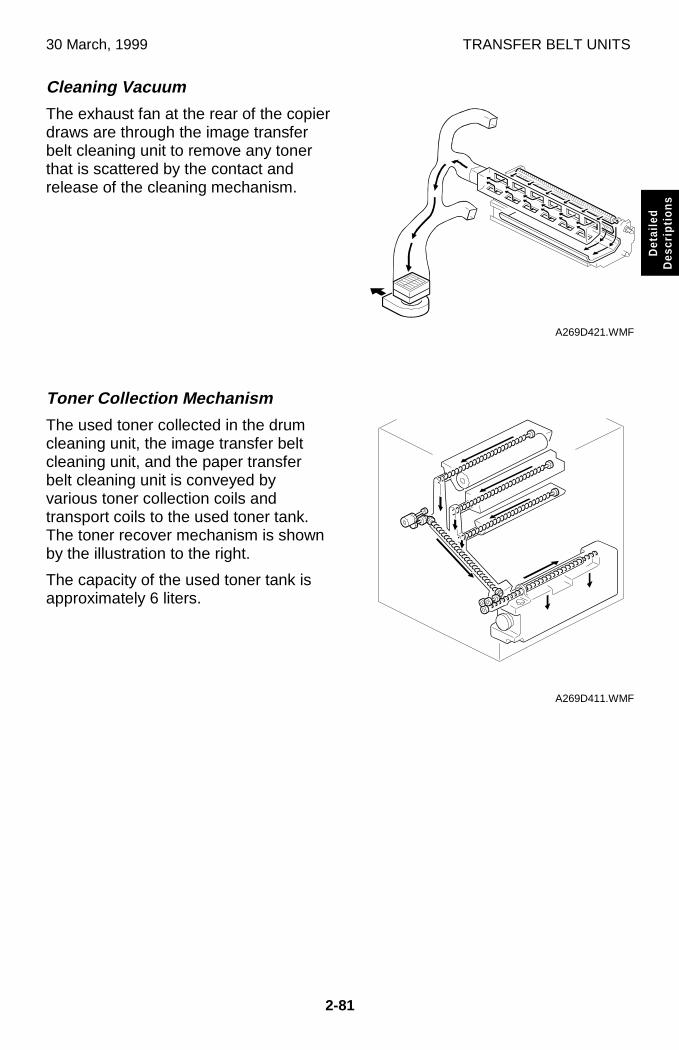
30 March, 1999 TRANSFER BELT UNITS
2-81
Det
aile
dD
escr
iptio
ns
Cleaning Vacuum
The exhaust fan at the rear of the copierdraws are through the image transferbelt cleaning unit to remove any tonerthat is scattered by the contact andrelease of the cleaning mechanism.
Toner Collection Mechanism
The used toner collected in the drumcleaning unit, the image transfer beltcleaning unit, and the paper transferbelt cleaning unit is conveyed byvarious toner collection coils andtransport coils to the used toner tank.The toner recover mechanism is shownby the illustration to the right.
The capacity of the used toner tank isapproximately 6 liters.
A269D421.WMF
A269D411.WMF
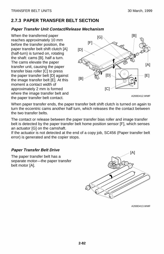
TRANSFER BELT UNITS 30 March, 1999
2-82
2.7.3 PAPER TRANSFER BELT SECTION
Paper Transfer Unit Contact/Release Mechanism
When the transferred paperreaches approximately 10 mmbefore the transfer position, thepaper transfer belt shift clutch [A](half-turn) is turned on, rotatingthe shaft: cams [B]. half a turn.The cams elevate the papertransfer unit, causing the papertransfer bias roller [C] to pressthe paper transfer belt [D] againstthe image transfer belt [E]. At thismoment a contact width ofapproximately 2 mm is formedwhere the image transfer belt andthe paper transfer belt contact.
When paper transfer ends, the paper transfer belt shift clutch is turned on again toturn the eccentric cams another half turn, which releases the the contact betweenthe two transfer belts.
The contact or release between the paper transfer bias roller and image transferbelt is detected by the paper transfer belt home position sensor [F], which sensesan actuator [G] on the camshaft.If the actuator is not detected at the end of a copy job, SC456 (Paper transfer belterror) is generated and the copier stops.
Paper Transfer Belt Drive
The paper transfer belt has aseparate motor—the paper transferbelt motor [A].
A269D412.WMF
A269D413.WMF
[E]
[B]
[A]
[B]
[D]
[F][G]
[A]
[C]
[D]
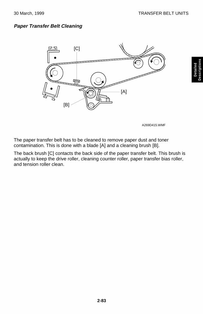
30 March, 1999 TRANSFER BELT UNITS
2-83
Det
aile
dD
escr
iptio
ns
Paper Transfer Belt Cleaning
The paper transfer belt has to be cleaned to remove paper dust and tonercontamination. This is done with a blade [A] and a cleaning brush [B].
The back brush [C] contacts the back side of the paper transfer belt. This brush isactually to keep the drive roller, cleaning counter roller, paper transfer bias roller,and tension roller clean.
A269D415.WMF
[A]
[C]
[B]
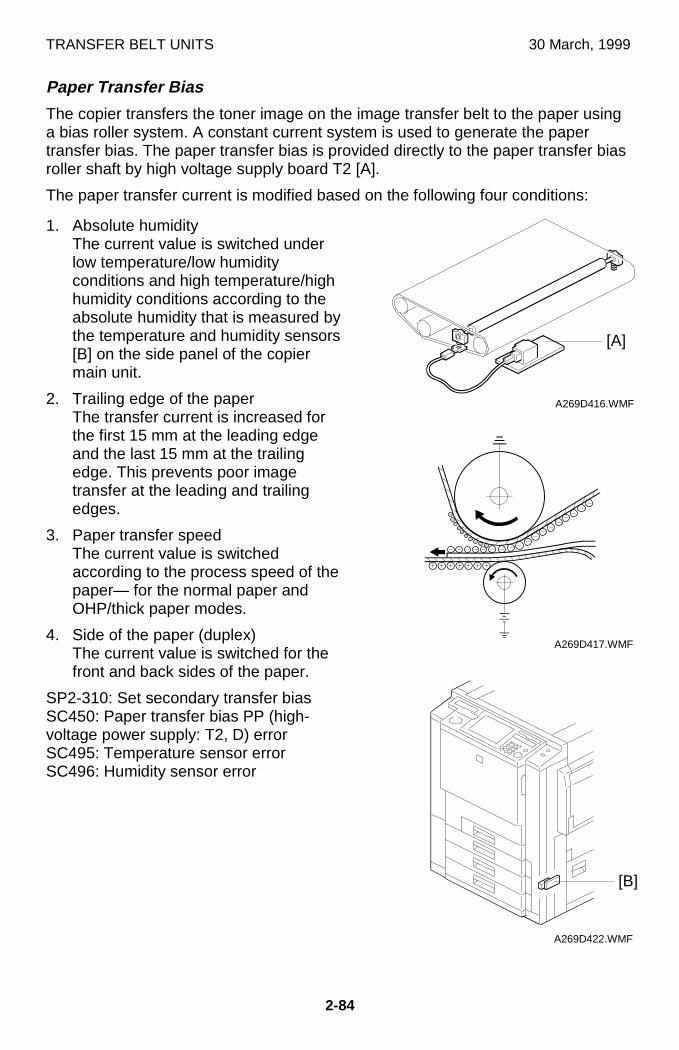
TRANSFER BELT UNITS 30 March, 1999
2-84
Paper Transfer Bias
The copier transfers the toner image on the image transfer belt to the paper usinga bias roller system. A constant current system is used to generate the papertransfer bias. The paper transfer bias is provided directly to the paper transfer biasroller shaft by high voltage supply board T2 [A].
The paper transfer current is modified based on the following four conditions:
1. Absolute humidityThe current value is switched underlow temperature/low humidityconditions and high temperature/highhumidity conditions according to theabsolute humidity that is measured bythe temperature and humidity sensors[B] on the side panel of the copiermain unit.
2. Trailing edge of the paperThe transfer current is increased forthe first 15 mm at the leading edgeand the last 15 mm at the trailingedge. This prevents poor imagetransfer at the leading and trailingedges.
3. Paper transfer speedThe current value is switchedaccording to the process speed of thepaper— for the normal paper andOHP/thick paper modes.
4. Side of the paper (duplex)The current value is switched for thefront and back sides of the paper.
SP2-310: Set secondary transfer biasSC450: Paper transfer bias PP (high-voltage power supply: T2, D) errorSC495: Temperature sensor errorSC496: Humidity sensor error
A269D416.WMF
A269D417.WMF
A269D422.WMF
[A]
[B]
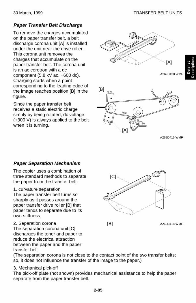
30 March, 1999 TRANSFER BELT UNITS
2-85
Det
aile
dD
escr
iptio
ns
Paper Transfer Belt Discharge
To remove the charges accumulatedon the paper transfer belt, a beltdischarge corona unit [A] is installedunder the unit near the drive roller.This corona unit removes thecharges that accumulate on thepaper transfer belt. The corona unitis an ac corotron with a dccomponent (5.8 kV ac, +600 dc).Charging starts when a pointcorresponding to the leading edge ofthe image reaches position [B] in thefigure.
Since the paper transfer beltreceives a static electric chargesimply by being rotated, dc voltage(+300 V) is always applied to the beltwhen it is turning.
Paper Separation Mechanism
The copier uses a combination ofthree standard methods to separatethe paper from the transfer belt.
1. curvature separationThe paper transfer belt turns sosharply as it passes around thepaper transfer drive roller [B] thatpaper tends to separate due to itsown stiffness.
2. Separation coronaThe separation corona unit [C]discharges the toner and paper toreduce the electrical attractionbetween the paper and the papertransfer belt.(The separation corona is not close to the contact point of the two transfer belts;so, it does not influence the transfer of the image to the paper.)
3. Mechanical pick-offThe pick-off plate (not shown) provides mechanical assistance to help the paperseparate from the paper transfer belt.
A269D420.WMF
A269D415.WMF
A269D418.WMF
[A]
[A]
[B]
[C]
[B]
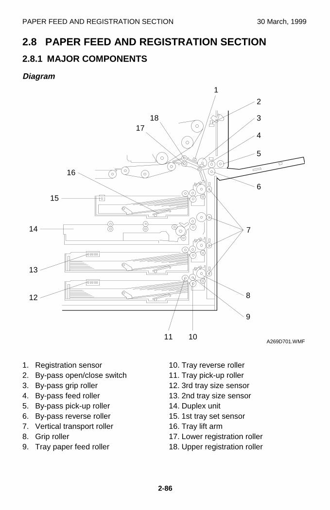
PAPER FEED AND REGISTRATION SECTION 30 March, 1999
2-86
2.8 PAPER FEED AND REGISTRATION SECTION
2.8.1 MAJOR COMPONENTS
Diagram
1. Registration sensor2. By-pass open/close switch3. By-pass grip roller4. By-pass feed roller5. By-pass pick-up roller6. By-pass reverse roller7. Vertical transport roller8. Grip roller9. Tray paper feed roller
10. Tray reverse roller11. Tray pick-up roller12. 3rd tray size sensor13. 2nd tray size sensor14. Duplex unit15. 1st tray set sensor16. Tray lift arm17. Lower registration roller18. Upper registration roller
A269D701.WMF
2
1
3
4
5
6
7
8
9
1011
12
13
14
15
16
1817
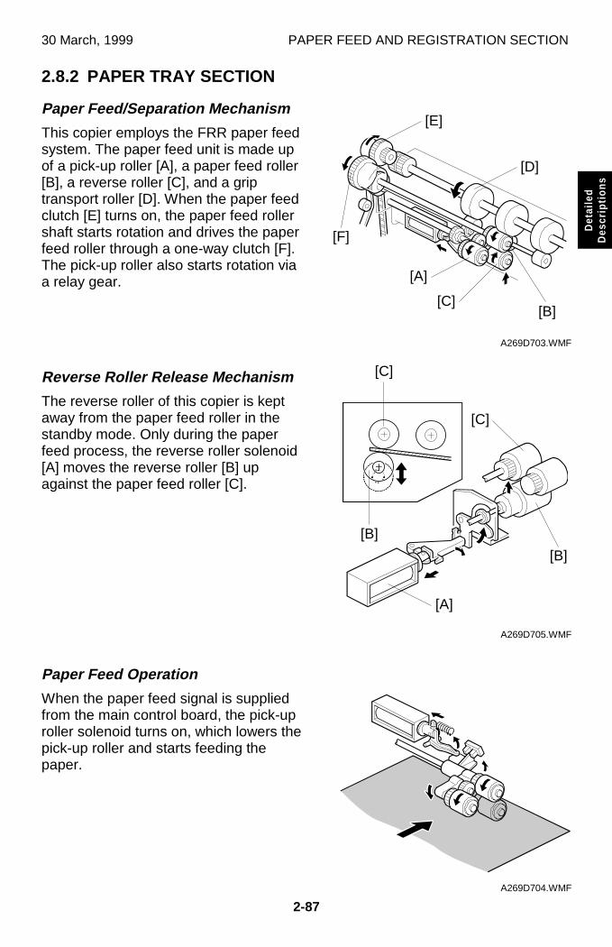
30 March, 1999 PAPER FEED AND REGISTRATION SECTION
2-87
Det
aile
dD
escr
iptio
ns
2.8.2 PAPER TRAY SECTION
Paper Feed/Separation Mechanism
This copier employs the FRR paper feedsystem. The paper feed unit is made upof a pick-up roller [A], a paper feed roller[B], a reverse roller [C], and a griptransport roller [D]. When the paper feedclutch [E] turns on, the paper feed rollershaft starts rotation and drives the paperfeed roller through a one-way clutch [F].The pick-up roller also starts rotation viaa relay gear.
Reverse Roller Release Mechanism
The reverse roller of this copier is keptaway from the paper feed roller in thestandby mode. Only during the paperfeed process, the reverse roller solenoid[A] moves the reverse roller [B] upagainst the paper feed roller [C].
Paper Feed Operation
When the paper feed signal is suppliedfrom the main control board, the pick-uproller solenoid turns on, which lowers thepick-up roller and starts feeding thepaper.
A269D703.WMF
A269D705.WMF
A269D704.WMF
[E]
[F]
[A]
[B]
[D]
[A]
[C][B]
[C]
[B]
[C]
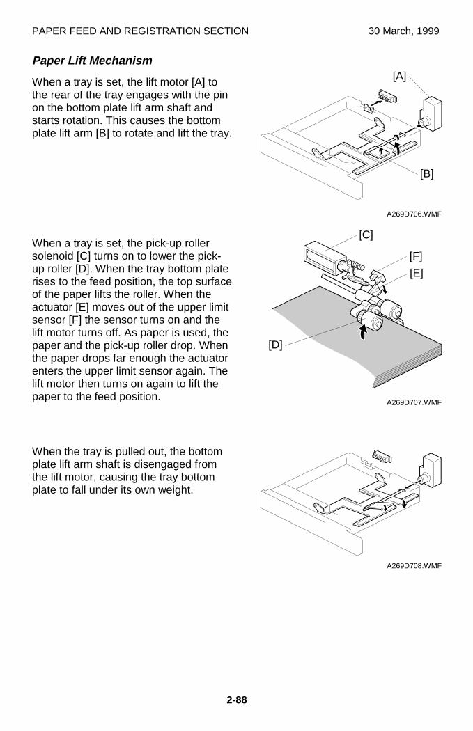
PAPER FEED AND REGISTRATION SECTION 30 March, 1999
2-88
Paper Lift Mechanism
When a tray is set, the lift motor [A] tothe rear of the tray engages with the pinon the bottom plate lift arm shaft andstarts rotation. This causes the bottomplate lift arm [B] to rotate and lift the tray.
When a tray is set, the pick-up rollersolenoid [C] turns on to lower the pick-up roller [D]. When the tray bottom platerises to the feed position, the top surfaceof the paper lifts the roller. When theactuator [E] moves out of the upper limitsensor [F] the sensor turns on and thelift motor turns off. As paper is used, thepaper and the pick-up roller drop. Whenthe paper drops far enough the actuatorenters the upper limit sensor again. Thelift motor then turns on again to lift thepaper to the feed position.
When the tray is pulled out, the bottomplate lift arm shaft is disengaged fromthe lift motor, causing the tray bottomplate to fall under its own weight.
A269D706.WMF
A269D707.WMF
A269D708.WMF
[B]
[C]
[A]
[F]
[E]
[D]
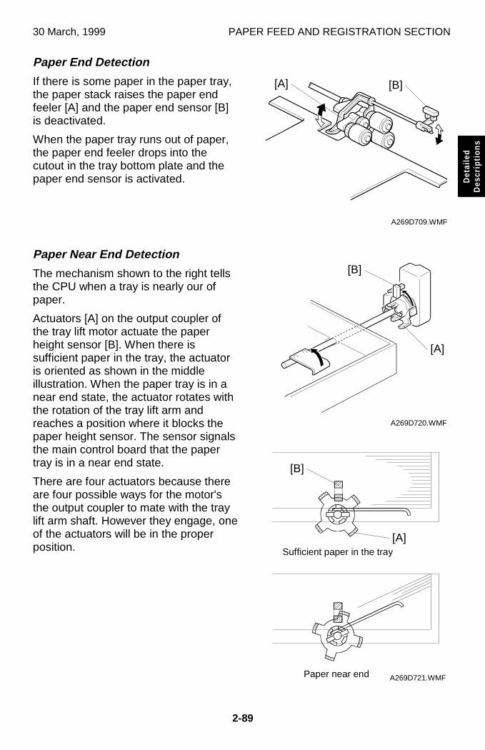
30 March, 1999 PAPER FEED AND REGISTRATION SECTION
2-89
Det
aile
dD
escr
iptio
ns
Paper End Detection
If there is some paper in the paper tray,the paper stack raises the paper endfeeler [A] and the paper end sensor [B]is deactivated.
When the paper tray runs out of paper,the paper end feeler drops into thecutout in the tray bottom plate and thepaper end sensor is activated.
Paper Near End Detection
The mechanism shown to the right tellsthe CPU when a tray is nearly our ofpaper.
Actuators [A] on the output coupler ofthe tray lift motor actuate the paperheight sensor [B]. When there issufficient paper in the tray, the actuatoris oriented as shown in the middleillustration. When the paper tray is in anear end state, the actuator rotates withthe rotation of the tray lift arm andreaches a position where it blocks thepaper height sensor. The sensor signalsthe main control board that the papertray is in a near end state.
There are four actuators because thereare four possible ways for the motor'sthe output coupler to mate with the traylift arm shaft. However they engage, oneof the actuators will be in the properposition.
A269D709.WMF
A269D720.WMF
A269D721.WMF
Sufficient paper in the tray
Paper near end
[B]
[B]
[A]
[A]
[A]
[B]
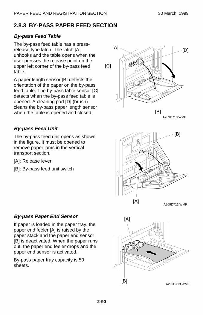
PAPER FEED AND REGISTRATION SECTION 30 March, 1999
2-90
2.8.3 BY-PASS PAPER FEED SECTION
By-pass Feed Table
The by-pass feed table has a press-release type latch. The latch [A]unhooks and the table opens when theuser presses the release point on theupper left corner of the by-pass feedtable.
A paper length sensor [B] detects theorientation of the paper on the by-passfeed table. The by-pass table sensor [C]detects when the by-pass feed table isopened. A cleaning pad [D] (brush)cleans the by-pass paper length sensorwhen the table is opened and closed.
By-pass Feed Unit
The by-pass feed unit opens as shownin the figure. It must be opened toremove paper jams in the verticaltransport section.
[A]: Release lever
[B]: By-pass feed unit switch
By-pass Paper End Sensor
If paper is loaded in the paper tray, thepaper end feeler [A] is raised by thepaper stack and the paper end sensor[B] is deactivated. When the paper runsout, the paper end feeler drops and thepaper end sensor is activated.
By-pass paper tray capacity is 50sheets.
A269D710.WMF
A269D711.WMF
A269D713.WMF
[A]
[B]
[A]
[A]
[C]
[D]
[B]
[B]
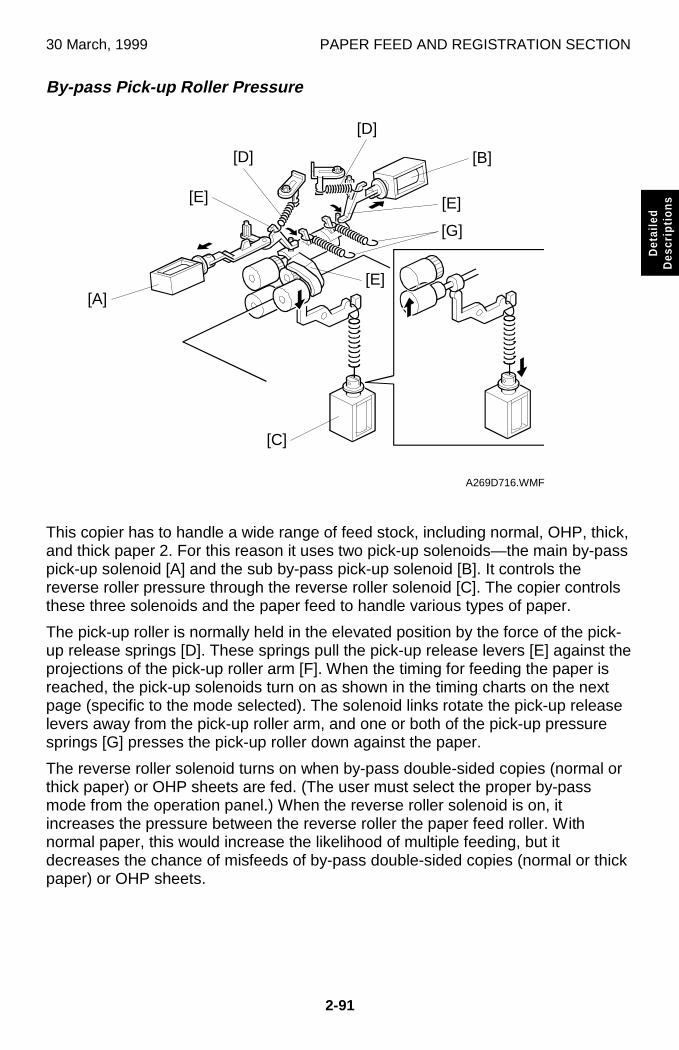
30 March, 1999 PAPER FEED AND REGISTRATION SECTION
2-91
Det
aile
dD
escr
iptio
ns
By-pass Pick-up Roller Pressure
This copier has to handle a wide range of feed stock, including normal, OHP, thick,and thick paper 2. For this reason it uses two pick-up solenoids—the main by-passpick-up solenoid [A] and the sub by-pass pick-up solenoid [B]. It controls thereverse roller pressure through the reverse roller solenoid [C]. The copier controlsthese three solenoids and the paper feed to handle various types of paper.
The pick-up roller is normally held in the elevated position by the force of the pick-up release springs [D]. These springs pull the pick-up release levers [E] against theprojections of the pick-up roller arm [F]. When the timing for feeding the paper isreached, the pick-up solenoids turn on as shown in the timing charts on the nextpage (specific to the mode selected). The solenoid links rotate the pick-up releaselevers away from the pick-up roller arm, and one or both of the pick-up pressuresprings [G] presses the pick-up roller down against the paper.
The reverse roller solenoid turns on when by-pass double-sided copies (normal orthick paper) or OHP sheets are fed. (The user must select the proper by-passmode from the operation panel.) When the reverse roller solenoid is on, itincreases the pressure between the reverse roller the paper feed roller. Withnormal paper, this would increase the likelihood of multiple feeding, but itdecreases the chance of misfeeds of by-pass double-sided copies (normal or thickpaper) or OHP sheets.
A269D716.WMF
[C]
[G]
[A]
[E]
[E]
[E]
[B]
[D]
[D]
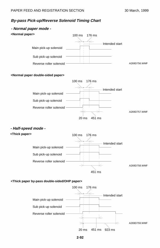
PAPER FEED AND REGISTRATION SECTION 30 March, 1999
2-92
By-pass Pick-up/Reverse Solenoid Timing Chart
A269D758.WMF
Reverse roller solenoid
Sub pick-up solenoid
Main pick-up solenoidIntended start
A269D759.WMF
Reverse roller solenoid
Sub pick-up solenoid
Main pick-up solenoidIntended start
Reverse roller solenoid
Sub pick-up solenoid
Main pick-up solenoidIntended start
A269D757.WMF
<Normal paper double-sided paper>
<Thick paper>
<Thick paper by-pass double-sided/OHP paper>
Reverse roller solenoid
Sub pick-up solenoid
100 ms 176 ms
Intended start
A269D756.WMF
<Normal paper>
- Normal paper mode -
- Half-speed mode -
100 ms 176 ms
451 ms
100 ms 176 ms
100 ms 176 ms
451 ms
20 ms
451 ms20 ms 923 ms
Main pick-up solenoid
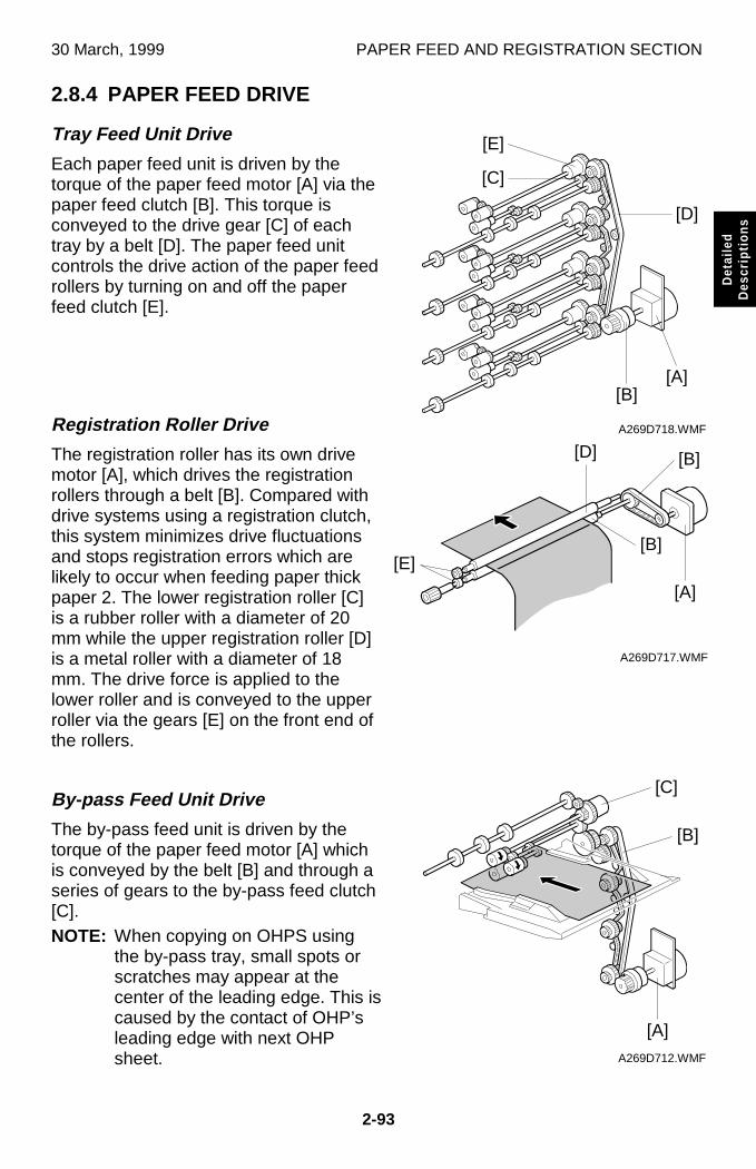
30 March, 1999 PAPER FEED AND REGISTRATION SECTION
2-93
Det
aile
dD
escr
iptio
ns
2.8.4 PAPER FEED DRIVE
Tray Feed Unit Drive
Each paper feed unit is driven by thetorque of the paper feed motor [A] via thepaper feed clutch [B]. This torque isconveyed to the drive gear [C] of eachtray by a belt [D]. The paper feed unitcontrols the drive action of the paper feedrollers by turning on and off the paperfeed clutch [E].
Registration Roller Drive
The registration roller has its own drivemotor [A], which drives the registrationrollers through a belt [B]. Compared withdrive systems using a registration clutch,this system minimizes drive fluctuationsand stops registration errors which arelikely to occur when feeding paper thickpaper 2. The lower registration roller [C]is a rubber roller with a diameter of 20mm while the upper registration roller [D]is a metal roller with a diameter of 18mm. The drive force is applied to thelower roller and is conveyed to the upperroller via the gears [E] on the front end ofthe rollers.
By-pass Feed Unit Drive
The by-pass feed unit is driven by thetorque of the paper feed motor [A] whichis conveyed by the belt [B] and through aseries of gears to the by-pass feed clutch[C].NOTE: When copying on OHPS using
the by-pass tray, small spots orscratches may appear at thecenter of the leading edge. This iscaused by the contact of OHP’sleading edge with next OHPsheet.
A269D718.WMF
A269D717.WMF
A269D712.WMF
[B]
[D]
[A]
[B]
[C]
[E]
[A]
[B]
[D]
[E]
[A]
[B]
[C]
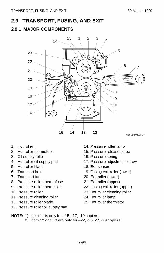
TRANSPORT, FUSING, AND EXIT 30 March, 1999
2-94
2.9 TRANSPORT, FUSING, AND EXIT
2.9.1 MAJOR COMPONENTS
1. Hot roller2. Hot roller thermofuse3. Oil supply roller4. Hot roller oil supply pad5. Hot roller blade6. Transport belt7. Transport fan8. Pressure roller thermofuse9. Pressure roller thermistor10. Pressure roller11. Pressure cleaning roller12. Pressure roller blade13. Pressure roller oil supply pad
14. Pressure roller lamp15. Pressure release screw16. Pressure spring17. Pressure adjustment screw18. Exit sensor19. Fusing exit roller (lower)20. Exit roller (lower)21. Exit roller (upper)22. Fusing exit roller (upper)23. Hot roller cleaning roller24. Hot roller lamp25. Hot roller thermistor
NOTE: 1) Item 11 is only for –15, -17, -19 copiers.2) Item 12 and 13 are only for –22, -26, 27, -29 copiers.
A269D501.WMF
8
13
9
10
12
16
17
18
19
20
21
22
23
3 4
76
5
2124
25
11
1415
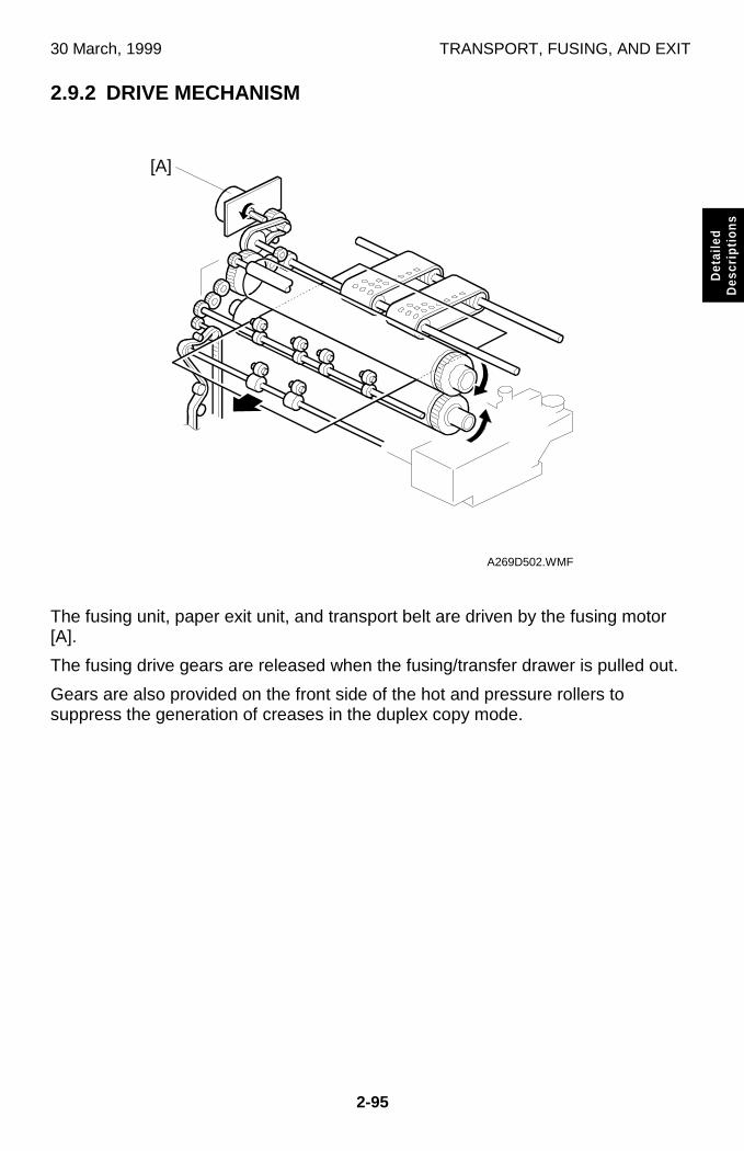
30 March, 1999 TRANSPORT, FUSING, AND EXIT
2-95
Det
aile
dD
escr
iptio
ns
2.9.2 DRIVE MECHANISM
The fusing unit, paper exit unit, and transport belt are driven by the fusing motor[A].
The fusing drive gears are released when the fusing/transfer drawer is pulled out.
Gears are also provided on the front side of the hot and pressure rollers tosuppress the generation of creases in the duplex copy mode.
A269D502.WMF
[A]
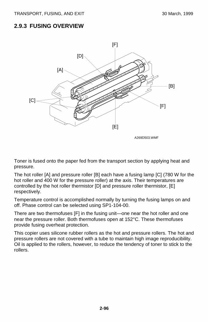
TRANSPORT, FUSING, AND EXIT 30 March, 1999
2-96
2.9.3 FUSING OVERVIEW
Toner is fused onto the paper fed from the transport section by applying heat andpressure.
The hot roller [A] and pressure roller [B] each have a fusing lamp [C] (780 W for thehot roller and 400 W for the pressure roller) at the axis. Their temperatures arecontrolled by the hot roller thermistor [D] and pressure roller thermistor, [E]respectively.
Temperature control is accomplished normally by turning the fusing lamps on andoff. Phase control can be selected using SP1-104-00.
There are two thermofuses [F] in the fusing unit—one near the hot roller and onenear the pressure roller. Both thermofuses open at 152°C. These thermofusesprovide fusing overheat protection.
This copier uses silicone rubber rollers as the hot and pressure rollers. The hot andpressure rollers are not covered with a tube to maintain high image reproducibility.Oil is applied to the rollers, however, to reduce the tendency of toner to stick to therollers.
A269D503.WMF
[E]
[B]
[F]
[F]
[D]
[A]
[C]
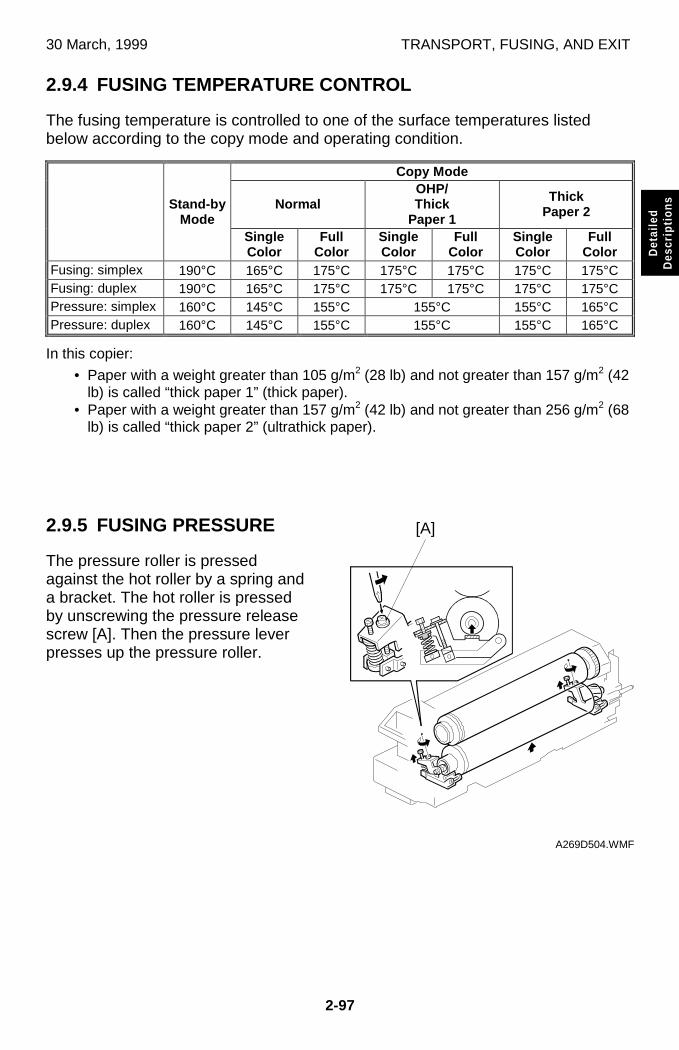
30 March, 1999 TRANSPORT, FUSING, AND EXIT
2-97
Det
aile
dD
escr
iptio
ns
2.9.4 FUSING TEMPERATURE CONTROL
The fusing temperature is controlled to one of the surface temperatures listedbelow according to the copy mode and operating condition.
Copy Mode
NormalOHP/Thick
Paper 1
ThickPaper 2Stand-by
ModeSingleColor
FullColor
SingleColor
FullColor
SingleColor
FullColor
Fusing: simplex 190°C 165°C 175°C 175°C 175°C 175°C 175°CFusing: duplex 190°C 165°C 175°C 175°C 175°C 175°C 175°CPressure: simplex 160°C 145°C 155°C 155°C 155°C 165°CPressure: duplex 160°C 145°C 155°C 155°C 155°C 165°C
In this copier:
• Paper with a weight greater than 105 g/m2 (28 lb) and not greater than 157 g/m2 (42lb) is called “thick paper 1” (thick paper).
• Paper with a weight greater than 157 g/m2 (42 lb) and not greater than 256 g/m2 (68lb) is called “thick paper 2” (ultrathick paper).
2.9.5 FUSING PRESSURE
The pressure roller is pressedagainst the hot roller by a spring anda bracket. The hot roller is pressedby unscrewing the pressure releasescrew [A]. Then the pressure leverpresses up the pressure roller.
A269D504.WMF
[A]
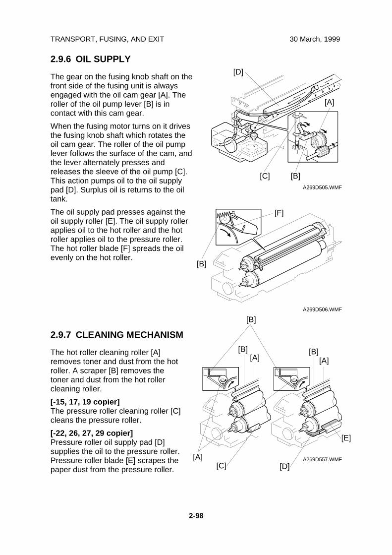
TRANSPORT, FUSING, AND EXIT 30 March, 1999
2-98
2.9.6 OIL SUPPLY
The gear on the fusing knob shaft on thefront side of the fusing unit is alwaysengaged with the oil cam gear [A]. Theroller of the oil pump lever [B] is incontact with this cam gear.
When the fusing motor turns on it drivesthe fusing knob shaft which rotates theoil cam gear. The roller of the oil pumplever follows the surface of the cam, andthe lever alternately presses andreleases the sleeve of the oil pump [C].This action pumps oil to the oil supplypad [D]. Surplus oil is returns to the oiltank.
The oil supply pad presses against theoil supply roller [E]. The oil supply rollerapplies oil to the hot roller and the hotroller applies oil to the pressure roller.The hot roller blade [F] spreads the oilevenly on the hot roller.
2.9.7 CLEANING MECHANISM
The hot roller cleaning roller [A]removes toner and dust from the hotroller. A scraper [B] removes thetoner and dust from the hot rollercleaning roller.
[-15, 17, 19 copier]The pressure roller cleaning roller [C]cleans the pressure roller.
[-22, 26, 27, 29 copier]Pressure roller oil supply pad [D]supplies the oil to the pressure roller.Pressure roller blade [E] scrapes thepaper dust from the pressure roller.
A269D505.WMF
A269D506.WMF
A269D557.WMF
[A]
[D]
[F]
[C] [B]
[B]
[C] [D]
[E]
[B][A]
[B][A]
[B]
[A]
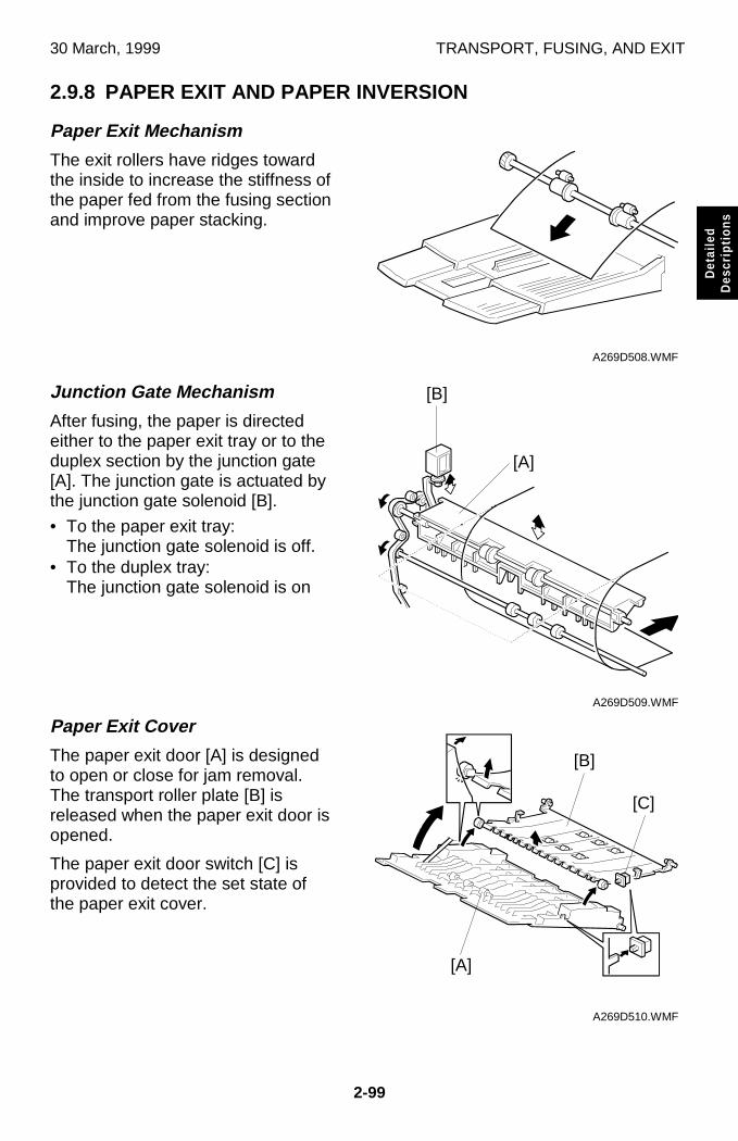
30 March, 1999 TRANSPORT, FUSING, AND EXIT
2-99
Det
aile
dD
escr
iptio
ns
2.9.8 PAPER EXIT AND PAPER INVERSION
Paper Exit Mechanism
The exit rollers have ridges towardthe inside to increase the stiffness ofthe paper fed from the fusing sectionand improve paper stacking.
Junction Gate Mechanism
After fusing, the paper is directedeither to the paper exit tray or to theduplex section by the junction gate[A]. The junction gate is actuated bythe junction gate solenoid [B].
• To the paper exit tray:The junction gate solenoid is off.
• To the duplex tray:The junction gate solenoid is on
Paper Exit Cover
The paper exit door [A] is designedto open or close for jam removal.The transport roller plate [B] isreleased when the paper exit door isopened.
The paper exit door switch [C] isprovided to detect the set state ofthe paper exit cover.
A269D508.WMF
A269D509.WMF
A269D510.WMF
[B]
[A]
[B]
[C]
[A]
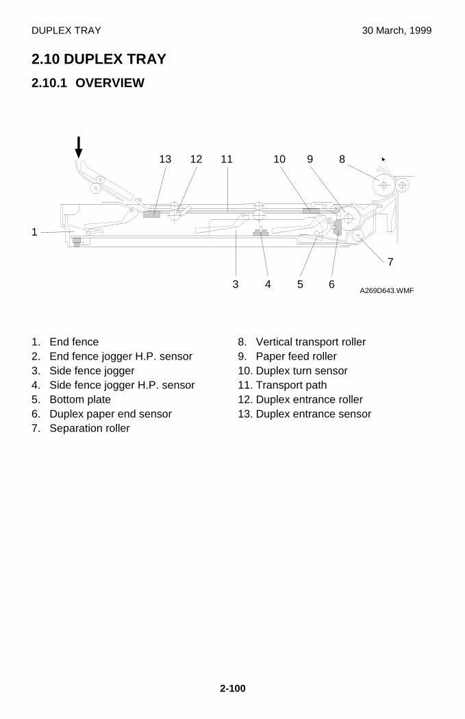
DUPLEX TRAY 30 March, 1999
2-100
2.10 DUPLEX TRAY
2.10.1 OVERVIEW
1. End fence2. End fence jogger H.P. sensor3. Side fence jogger4. Side fence jogger H.P. sensor5. Bottom plate6. Duplex paper end sensor7. Separation roller
8. Vertical transport roller9. Paper feed roller10. Duplex turn sensor11. Transport path12. Duplex entrance roller13. Duplex entrance sensor
A269D643.WMF
7
111213 10 9 8
3 4 5 6
1
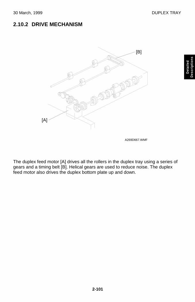
30 March, 1999 DUPLEX TRAY
2-101
Det
aile
dD
escr
iptio
ns
2.10.2 DRIVE MECHANISM
The duplex feed motor [A] drives all the rollers in the duplex tray using a series ofgears and a timing belt [B]. Helical gears are used to reduce noise. The duplexfeed motor also drives the duplex bottom plate up and down.
A269D667.WMF
[B]
[A]
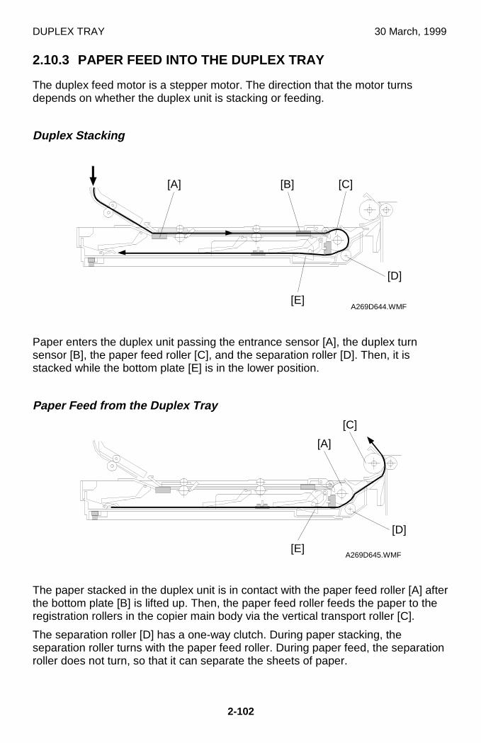
DUPLEX TRAY 30 March, 1999
2-102
2.10.3 PAPER FEED INTO THE DUPLEX TRAY
The duplex feed motor is a stepper motor. The direction that the motor turnsdepends on whether the duplex unit is stacking or feeding.
Duplex Stacking
Paper enters the duplex unit passing the entrance sensor [A], the duplex turnsensor [B], the paper feed roller [C], and the separation roller [D]. Then, it isstacked while the bottom plate [E] is in the lower position.
Paper Feed from the Duplex Tray
The paper stacked in the duplex unit is in contact with the paper feed roller [A] afterthe bottom plate [B] is lifted up. Then, the paper feed roller feeds the paper to theregistration rollers in the copier main body via the vertical transport roller [C].
The separation roller [D] has a one-way clutch. During paper stacking, theseparation roller turns with the paper feed roller. During paper feed, the separationroller does not turn, so that it can separate the sheets of paper.
A269D644.WMF
A269D645.WMF
[D]
[C][B][A]
[E]
[D]
[E]
[C]
[A]
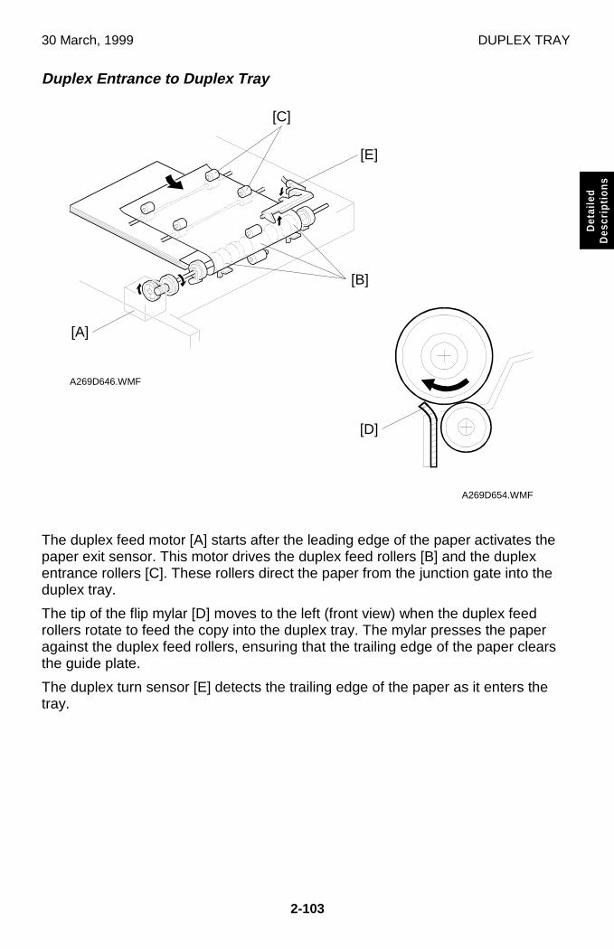
30 March, 1999 DUPLEX TRAY
2-103
Det
aile
dD
escr
iptio
ns
Duplex Entrance to Duplex Tray
The duplex feed motor [A] starts after the leading edge of the paper activates thepaper exit sensor. This motor drives the duplex feed rollers [B] and the duplexentrance rollers [C]. These rollers direct the paper from the junction gate into theduplex tray.
The tip of the flip mylar [D] moves to the left (front view) when the duplex feedrollers rotate to feed the copy into the duplex tray. The mylar presses the paperagainst the duplex feed rollers, ensuring that the trailing edge of the paper clearsthe guide plate.
The duplex turn sensor [E] detects the trailing edge of the paper as it enters thetray.
A269D654.WMF
A269D646.WMF
[E]
[C]
[D]
[A]
[B]
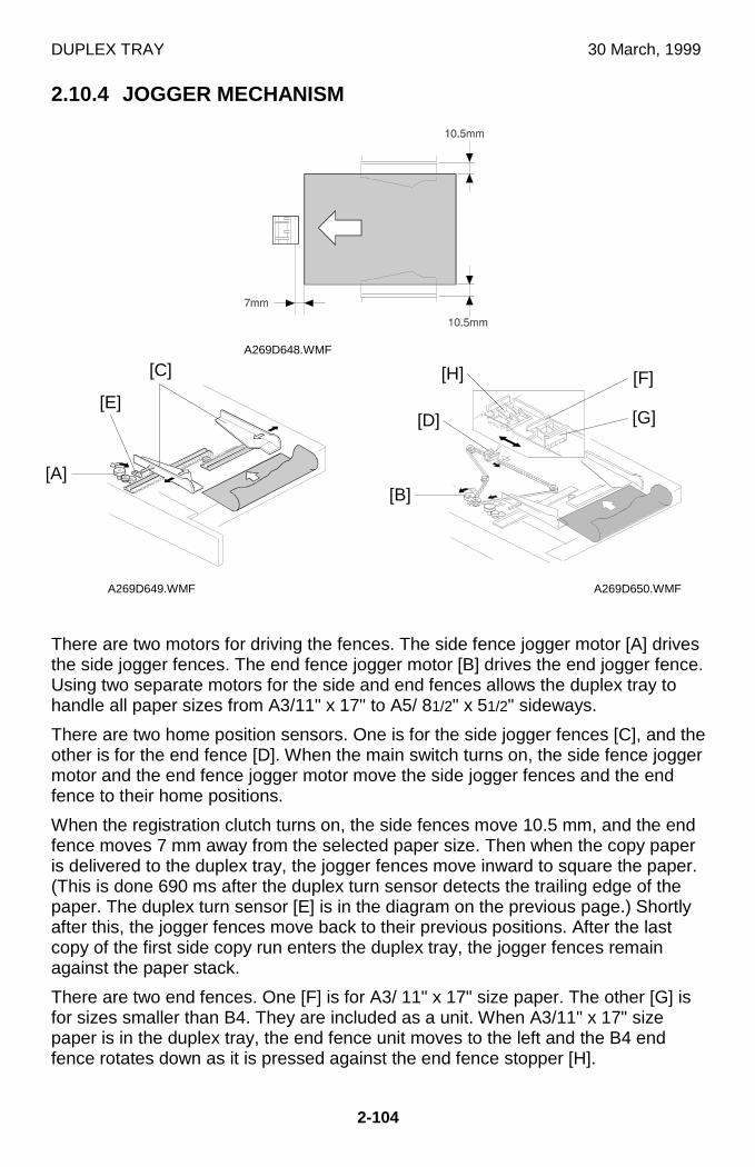
DUPLEX TRAY 30 March, 1999
2-104
2.10.4 JOGGER MECHANISM
There are two motors for driving the fences. The side fence jogger motor [A] drivesthe side jogger fences. The end fence jogger motor [B] drives the end jogger fence.Using two separate motors for the side and end fences allows the duplex tray tohandle all paper sizes from A3/11" x 17" to A5/ 81/2" x 51/2" sideways.
There are two home position sensors. One is for the side jogger fences [C], and theother is for the end fence [D]. When the main switch turns on, the side fence joggermotor and the end fence jogger motor move the side jogger fences and the endfence to their home positions.
When the registration clutch turns on, the side fences move 10.5 mm, and the endfence moves 7 mm away from the selected paper size. Then when the copy paperis delivered to the duplex tray, the jogger fences move inward to square the paper.(This is done 690 ms after the duplex turn sensor detects the trailing edge of thepaper. The duplex turn sensor [E] is in the diagram on the previous page.) Shortlyafter this, the jogger fences move back to their previous positions. After the lastcopy of the first side copy run enters the duplex tray, the jogger fences remainagainst the paper stack.
There are two end fences. One [F] is for A3/ 11" x 17" size paper. The other [G] isfor sizes smaller than B4. They are included as a unit. When A3/11" x 17" sizepaper is in the duplex tray, the end fence unit moves to the left and the B4 endfence rotates down as it is pressed against the end fence stopper [H].
A269D649.WMF
A269D648.WMF
A269D650.WMF
[E][G]
[F]
[B]
[D]
[H]
[A]
[C]
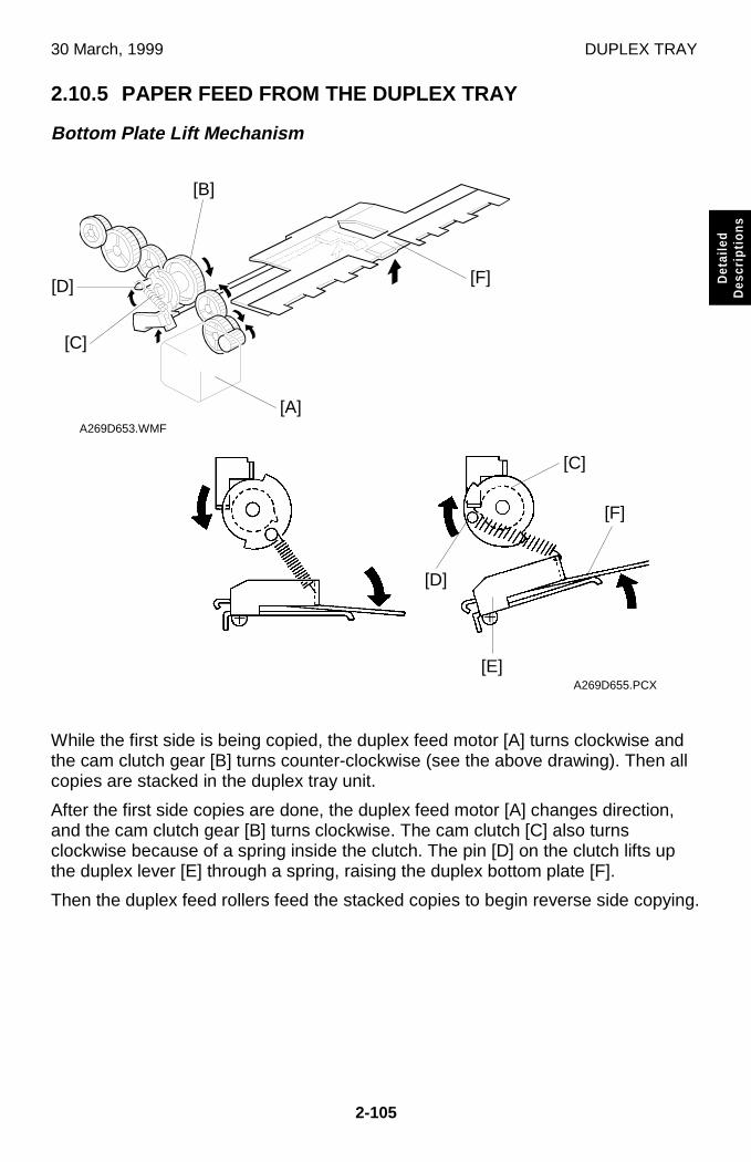
30 March, 1999 DUPLEX TRAY
2-105
Det
aile
dD
escr
iptio
ns
2.10.5 PAPER FEED FROM THE DUPLEX TRAY
Bottom Plate Lift Mechanism
While the first side is being copied, the duplex feed motor [A] turns clockwise andthe cam clutch gear [B] turns counter-clockwise (see the above drawing). Then allcopies are stacked in the duplex tray unit.
After the first side copies are done, the duplex feed motor [A] changes direction,and the cam clutch gear [B] turns clockwise. The cam clutch [C] also turnsclockwise because of a spring inside the clutch. The pin [D] on the clutch lifts upthe duplex lever [E] through a spring, raising the duplex bottom plate [F].
Then the duplex feed rollers feed the stacked copies to begin reverse side copying.
A269D653.WMF
A269D655.PCX
[B]
[D]
[C]
[A]
[F]
[E]
[C]
[D]
[F]
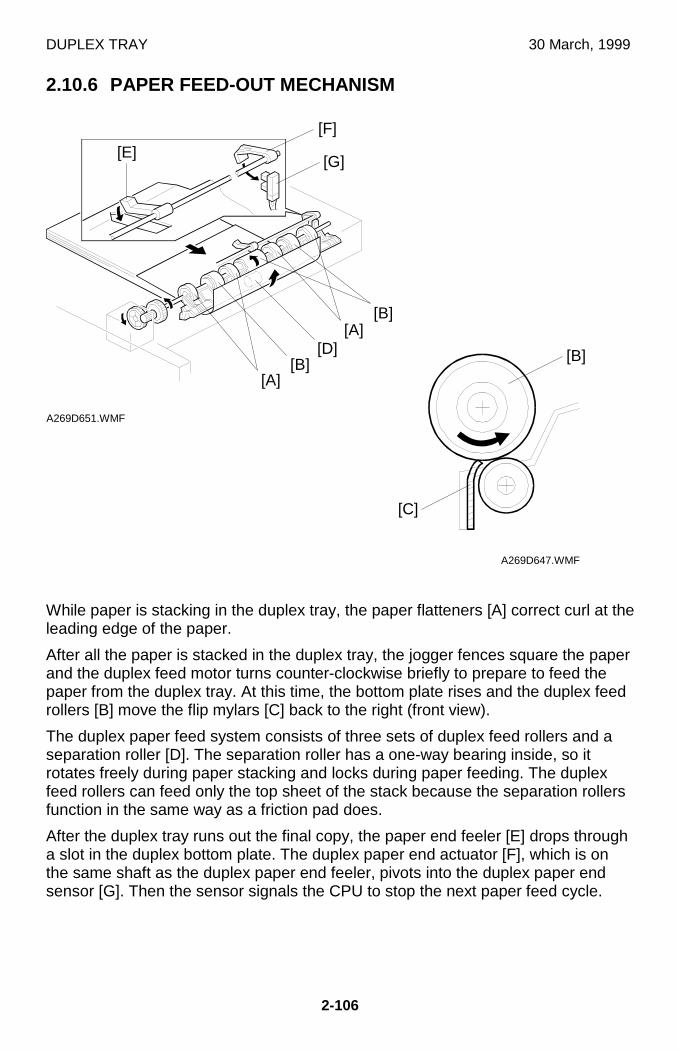
DUPLEX TRAY 30 March, 1999
2-106
2.10.6 PAPER FEED-OUT MECHANISM
While paper is stacking in the duplex tray, the paper flatteners [A] correct curl at theleading edge of the paper.
After all the paper is stacked in the duplex tray, the jogger fences square the paperand the duplex feed motor turns counter-clockwise briefly to prepare to feed thepaper from the duplex tray. At this time, the bottom plate rises and the duplex feedrollers [B] move the flip mylars [C] back to the right (front view).
The duplex paper feed system consists of three sets of duplex feed rollers and aseparation roller [D]. The separation roller has a one-way bearing inside, so itrotates freely during paper stacking and locks during paper feeding. The duplexfeed rollers can feed only the top sheet of the stack because the separation rollersfunction in the same way as a friction pad does.
After the duplex tray runs out the final copy, the paper end feeler [E] drops througha slot in the duplex bottom plate. The duplex paper end actuator [F], which is onthe same shaft as the duplex paper end feeler, pivots into the duplex paper endsensor [G]. Then the sensor signals the CPU to stop the next paper feed cycle.
A269D651.WMF
A269D647.WMF
[E][G]
[C]
[B]
[F]
[D][B]
[A]
[A][B]
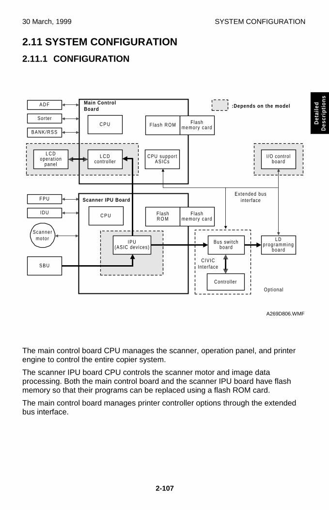
30 March, 1999 SYSTEM CONFIGURATION
2-107
Det
aile
dD
escr
iptio
ns
2.11 SYSTEM CONFIGURATION
2.11.1 CONFIGURATION
The main control board CPU manages the scanner, operation panel, and printerengine to control the entire copier system.
The scanner IPU board CPU controls the scanner motor and image dataprocessing. Both the main control board and the scanner IPU board have flashmemory so that their programs can be replaced using a flash ROM card.
The main control board manages printer controller options through the extendedbus interface.
CPU suppor tASICs
L C Dcontrol ler
L C Doperat ion
panel
C P U Flash ROM Flashmemory card
Main ControlBoard
C P U FlashR O M
Flashmemory card
Scanner IPU Board
Bus switchboard
LDprogramming
board
S B U
A D F
Sorter
BANK/RSS
F P U
IDU
Scannermotor
CIVICInterface
Extended businterface
I/O controlboard
Control ler
Opt ional
:Depends on the model
IPU(ASIC devices)
A269D806.WMF

SYSTEM CONFIGURATION 30 March, 1999
2-108
2.11.2 NORMAL COPY MODE
This copier has three power supply modes.
Main Power Switch Off State
When the main power switch is turned off, the power to the following heaters isturned on to prevent condensation.
These heaters are powered off by relays on the AC drive when the main powerswitch is turned on.
• Optics auto condensation heater• Paper transfer heater• Paper tray heaters
Power-off (Sleep) State
The power-off state of this copier conforms to the International Energy Starstandard for “Sleep Mode”. Of the DC outputs (VAA, VCA, VCB, VCC1, and VCC2)from the PSU, only VCC2 is turned on; all of the other outputs are held off. In thisstate, power is applied only to the main control board and the operation switch, sothat the machine can detect when the operation switch is pressed. In this state, thefusing lamps are off.
When the main board detects that the operation switch was pressed, the machinegoes back to standby mode.
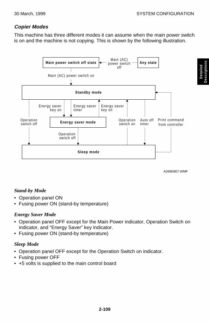
30 March, 1999 SYSTEM CONFIGURATION
2-109
Det
aile
dD
escr
iptio
ns
Copier Modes
This machine has three different modes it can assume when the main power switchis on and the machine is not copying. This is shown by the following illustration.
Stand-by Mode• Operation panel ON• Fusing power ON (stand-by temperature)
Energy Saver Mode• Operation panel OFF except for the Main Power indicator, Operation Switch on
indicator, and “Energy Saver” key indicator.• Fusing power ON (stand-by temperature)
Sleep Mode• Operation panel OFF except for the Operation Switch on indicator.• Fusing power OFF• +5 volts is supplied to the main control board
Standby mode
Sleep mode
Main power switch off stateMain (AC)
power swi tchoff
Main (AC) power swi tch on
Energy saverkey on
Energy savert imer
Energy saver mode
Any state
Operat ionswitch on
Energy saverkey on
Operat ionswitch off
Operat ionswitch off
Pr in t commandfrom control ler
Auto of ft imer
A269D807.WMF
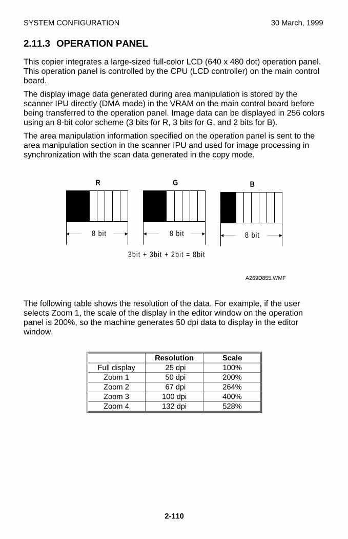
SYSTEM CONFIGURATION 30 March, 1999
2-110
2.11.3 OPERATION PANEL
This copier integrates a large-sized full-color LCD (640 x 480 dot) operation panel.This operation panel is controlled by the CPU (LCD controller) on the main controlboard.
The display image data generated during area manipulation is stored by thescanner IPU directly (DMA mode) in the VRAM on the main control board beforebeing transferred to the operation panel. Image data can be displayed in 256 colorsusing an 8-bit color scheme (3 bits for R, 3 bits for G, and 2 bits for B).
The area manipulation information specified on the operation panel is sent to thearea manipulation section in the scanner IPU and used for image processing insynchronization with the scan data generated in the copy mode.
The following table shows the resolution of the data. For example, if the userselects Zoom 1, the scale of the display in the editor window on the operationpanel is 200%, so the machine generates 50 dpi data to display in the editorwindow.
Resolution ScaleFull display 25 dpi 100%
Zoom 1 50 dpi 200%Zoom 2 67 dpi 264%Zoom 3 100 dpi 400%Zoom 4 132 dpi 528%
�����������������������������������
���������������������������������������������
�����������������������������������
8 bit
R ��������������������������������������������������
����������������������������������������
��������������������������������������������������
8 bit
G ���������������������������������������������
�����������������������������������
8 bit
B
3bit + 3bit + 2bit = 8bit
A269D855.WMF
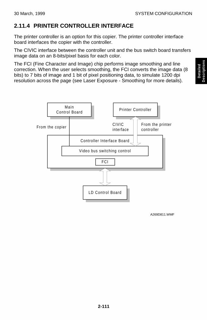
30 March, 1999 SYSTEM CONFIGURATION
2-111
Det
aile
dD
escr
iptio
ns
2.11.4 PRINTER CONTROLLER INTERFACE
The printer controller is an option for this copier. The printer controller interfaceboard interfaces the copier with the controller.
The CIVIC interface between the controller unit and the bus switch board transfersimage data on an 8-bits/pixel basis for each color.
The FCI (Fine Character and Image) chip performs image smoothing and linecorrection. When the user selects smoothing, the FCI converts the image data (8bits) to 7 bits of image and 1 bit of pixel positioning data, to simulate 1200 dpiresolution across the page (see Laser Exposure - Smoothing for more details).
MainControl Board
Control ler Interface Board
LD Control Board
FCI
Video bus switching control
Printer Control ler
From the copierFrom the printercontrol ler
CIVICinterface
A269D811.WMF
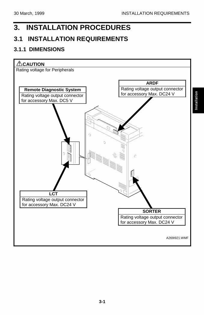
30 March, 1999 INSTALLATION REQUIREMENTS
3-1
Inst
alla
tion
3. INSTALLATION PROCEDURES
3.1 INSTALLATION REQUIREMENTS
3.1.1 DIMENSIONS
øCAUTIONRating voltage for Peripherals
A269I921.WMF
ARDFRating voltage output connectorfor accessory Max. DC24 V
SORTERRating voltage output connectorfor accessory Max. DC24 V
LCTRating voltage output connectorfor accessory Max. DC24 V
Remote Diagnostic SystemRating voltage output connectorfor accessory Max. DC5 V
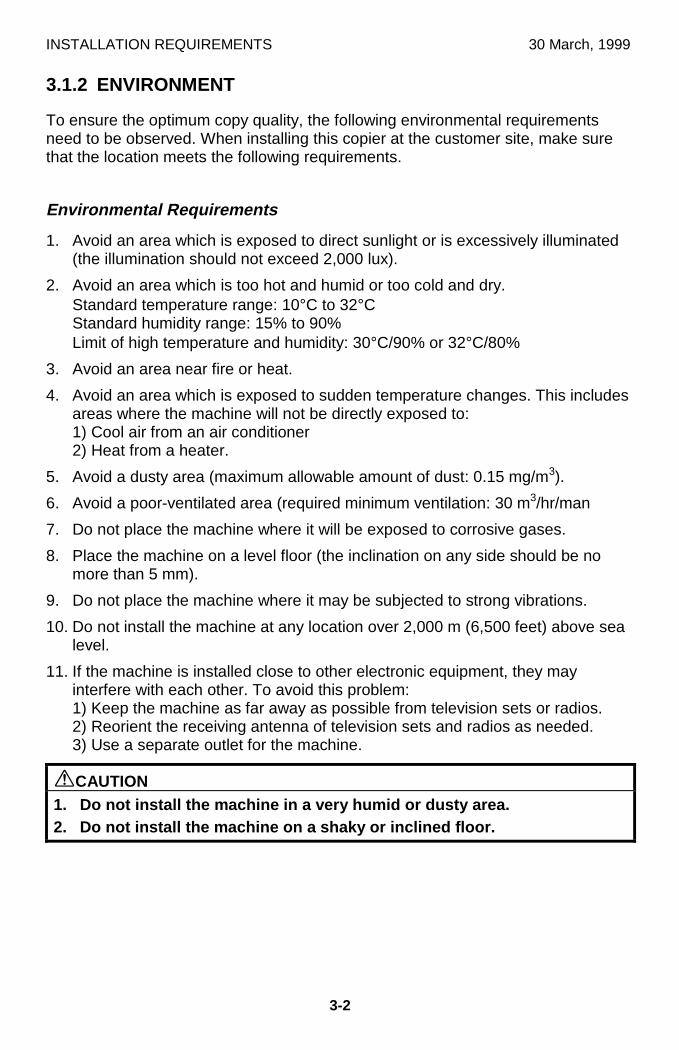
INSTALLATION REQUIREMENTS 30 March, 1999
3-2
3.1.2 ENVIRONMENT
To ensure the optimum copy quality, the following environmental requirementsneed to be observed. When installing this copier at the customer site, make surethat the location meets the following requirements.
Environmental Requirements
1. Avoid an area which is exposed to direct sunlight or is excessively illuminated(the illumination should not exceed 2,000 lux).
2. Avoid an area which is too hot and humid or too cold and dry.Standard temperature range: 10°C to 32°CStandard humidity range: 15% to 90%Limit of high temperature and humidity: 30°C/90% or 32°C/80%
3. Avoid an area near fire or heat.
4. Avoid an area which is exposed to sudden temperature changes. This includesareas where the machine will not be directly exposed to:1) Cool air from an air conditioner2) Heat from a heater.
5. Avoid a dusty area (maximum allowable amount of dust: 0.15 mg/m3).
6. Avoid a poor-ventilated area (required minimum ventilation: 30 m3/hr/man
7. Do not place the machine where it will be exposed to corrosive gases.
8. Place the machine on a level floor (the inclination on any side should be nomore than 5 mm).
9. Do not place the machine where it may be subjected to strong vibrations.
10. Do not install the machine at any location over 2,000 m (6,500 feet) above sealevel.
11. If the machine is installed close to other electronic equipment, they mayinterfere with each other. To avoid this problem:1) Keep the machine as far away as possible from television sets or radios.2) Reorient the receiving antenna of television sets and radios as needed.3) Use a separate outlet for the machine.
øCAUTION1. Do not install the machine in a very humid or dusty area.2. Do not install the machine on a shaky or inclined floor.
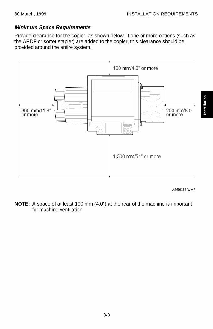
30 March, 1999 INSTALLATION REQUIREMENTS
3-3
Inst
alla
tion
Minimum Space Requirements
Provide clearance for the copier, as shown below. If one or more options (such asthe ARDF or sorter stapler) are added to the copier, this clearance should beprovided around the entire system.
NOTE: A space of at least 100 mm (4.0") at the rear of the machine is importantfor machine ventilation.
A269I157.WMF
INSTALLATION REQUIREMENTS 30 March, 1999
3-4
Power Requirements
øWARNING1. Install the machine as close to the outlet as possible. Firmly plug in the
machine after installation.2. Avoid multi-wiring.3. The power cord should be placed where it cannot be stepped on or
flattened by the machine. When installing the machine, route the powercord out of the way of general traffic.
4. Be sure to connect the power cord’s grounding wire.
1. Input voltage level:120 V, 60 Hz: More than 16 A (North America)220 V to 240 V, 50 Hz: More than 8 A (Europe, Middle Ease)220 V to 240 V, 50/60 Hz: More than 8 A (Asia)
2. Permissible voltage fluctuation: ±10%
3. Do not set anything on the power cord.

30 March, 1999 COPIER
3-5
Inst
alla
tion
3.2 COPIER
3.2.1 ACCESSORY CHECK
Description Q’ty
1. Operating Instructions Quick Reference............................... 1
2. Operating Instructions manual.............................................. 1
3. Touch panel pen................................................................... 1
4. Copy tray .............................................................................. 1
5. Tray size decal ..................................................................... 1
6. Image samples ..................................................................... 1
7. Factory data sheet................................................................ 1
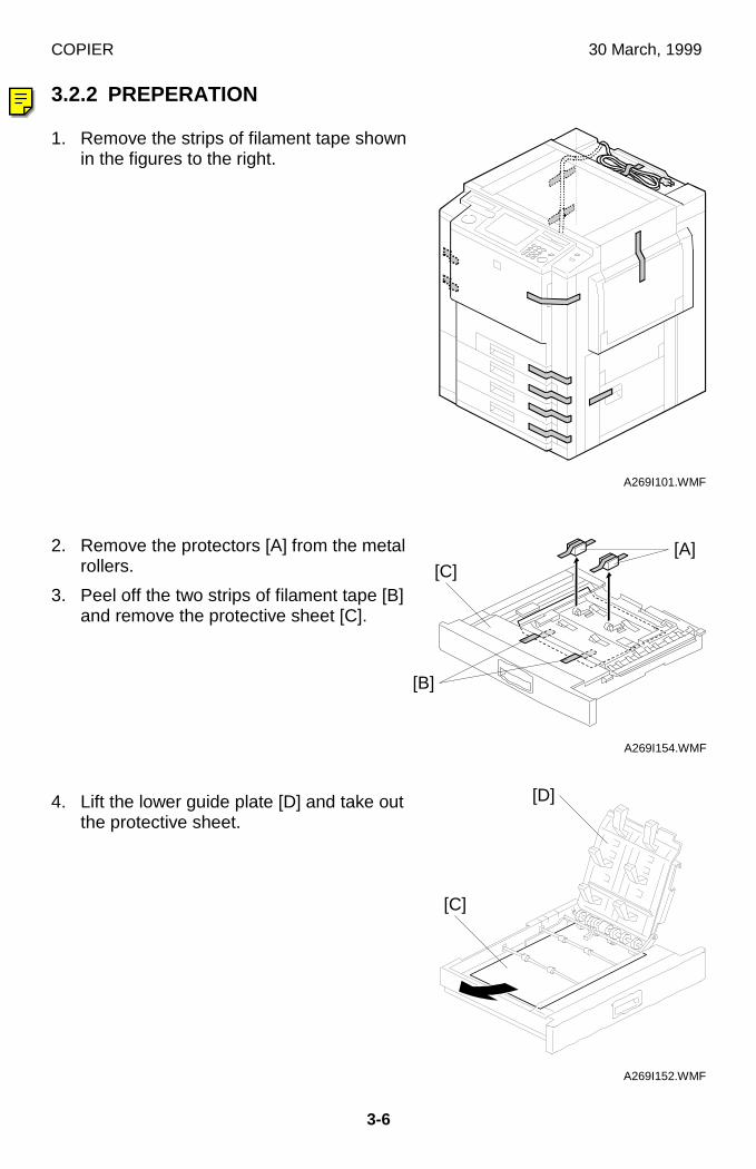
COPIER 30 March, 1999
3-6
3.2.2 PREPERATION
1. Remove the strips of filament tape shownin the figures to the right.
2. Remove the protectors [A] from the metalrollers.
3. Peel off the two strips of filament tape [B]and remove the protective sheet [C].
4. Lift the lower guide plate [D] and take outthe protective sheet.
A269I101.WMF
A269I154.WMF
A269I152.WMF
[C]
[D]
[B]
[C][A]
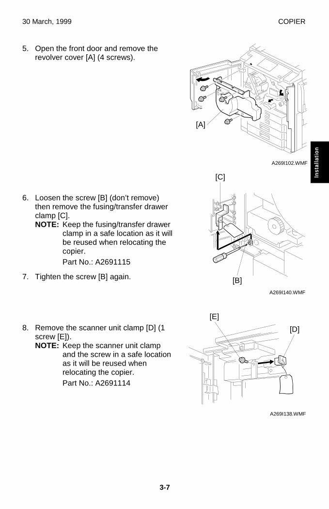
30 March, 1999 COPIER
3-7
Inst
alla
tion
5. Open the front door and remove therevolver cover [A] (4 screws).
6. Loosen the screw [B] (don’t remove)then remove the fusing/transfer drawerclamp [C].NOTE: Keep the fusing/transfer drawer
clamp in a safe location as it willbe reused when relocating thecopier.Part No.: A2691115
7. Tighten the screw [B] again.
8. Remove the scanner unit clamp [D] (1screw [E]).NOTE: Keep the scanner unit clamp
and the screw in a safe locationas it will be reused whenrelocating the copier.Part No.: A2691114
A269I102.WMF
A269I140.WMF
A269I138.WMF
[B]
[A]
[C]
[D]
[E]
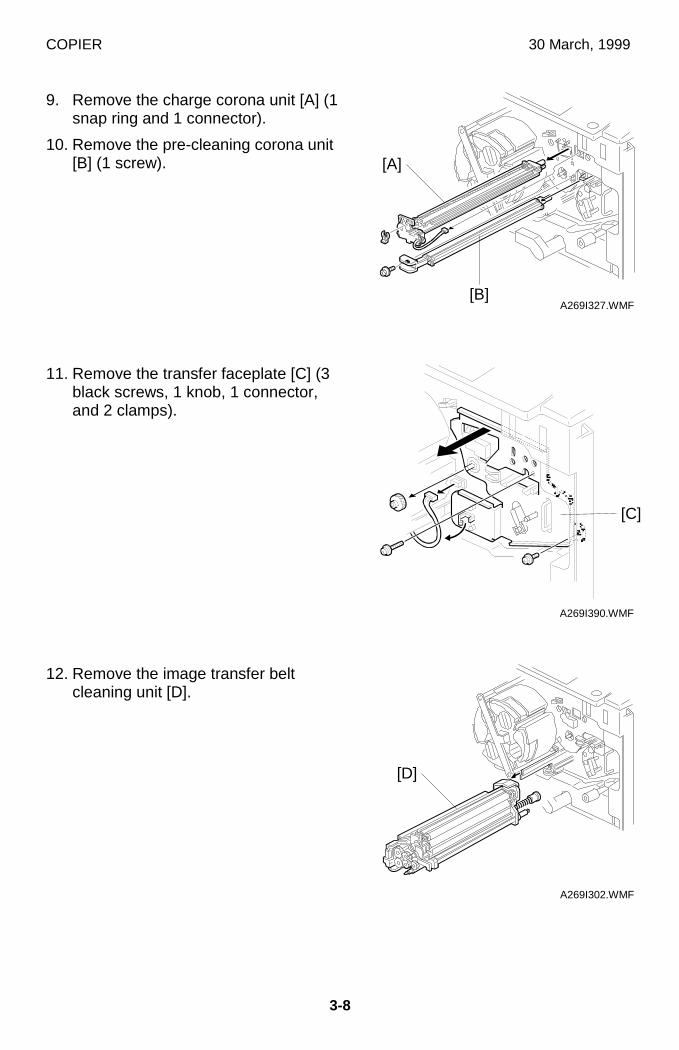
COPIER 30 March, 1999
3-8
9. Remove the charge corona unit [A] (1snap ring and 1 connector).
10. Remove the pre-cleaning corona unit[B] (1 screw).
11. Remove the transfer faceplate [C] (3black screws, 1 knob, 1 connector,and 2 clamps).
12. Remove the image transfer beltcleaning unit [D].
A269I327.WMF
A269I390.WMF
A269I302.WMF
[A]
[B]
[D]
[C]
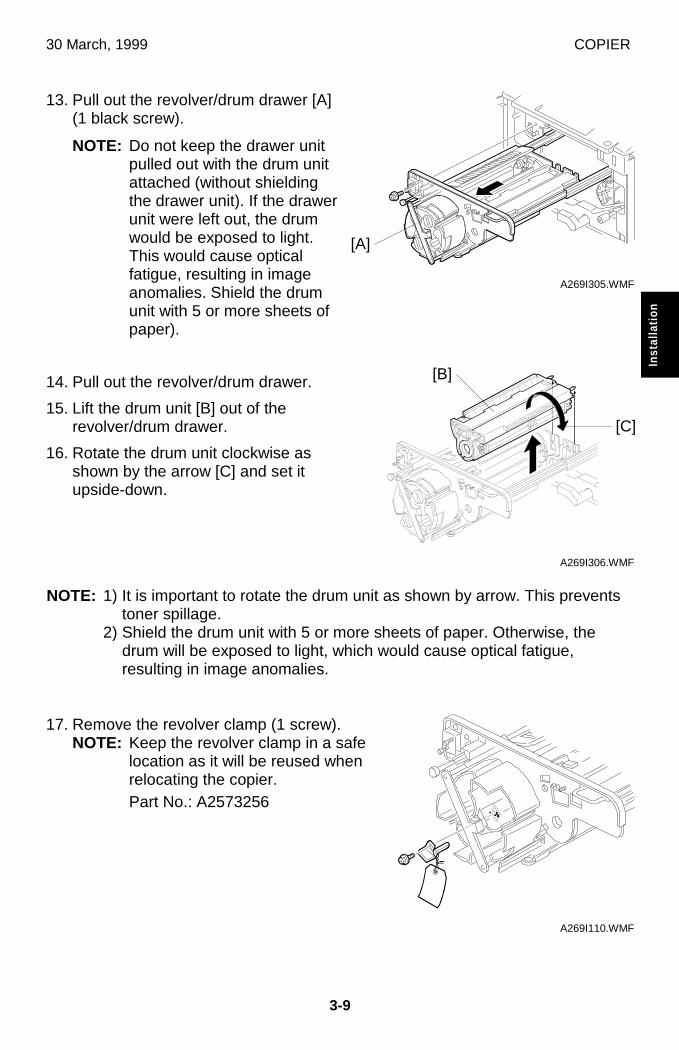
30 March, 1999 COPIER
3-9
Inst
alla
tion
13. Pull out the revolver/drum drawer [A](1 black screw).
NOTE: Do not keep the drawer unitpulled out with the drum unitattached (without shieldingthe drawer unit). If the drawerunit were left out, the drumwould be exposed to light.This would cause opticalfatigue, resulting in imageanomalies. Shield the drumunit with 5 or more sheets ofpaper).
14. Pull out the revolver/drum drawer.
15. Lift the drum unit [B] out of therevolver/drum drawer.
16. Rotate the drum unit clockwise asshown by the arrow [C] and set itupside-down.
NOTE: 1) It is important to rotate the drum unit as shown by arrow. This preventstoner spillage.
2) Shield the drum unit with 5 or more sheets of paper. Otherwise, thedrum will be exposed to light, which would cause optical fatigue,resulting in image anomalies.
17. Remove the revolver clamp (1 screw).NOTE: Keep the revolver clamp in a safe
location as it will be reused whenrelocating the copier.Part No.: A2573256
A269I305.WMF
A269I306.WMF
A269I110.WMF
[A]
[B]
[C]
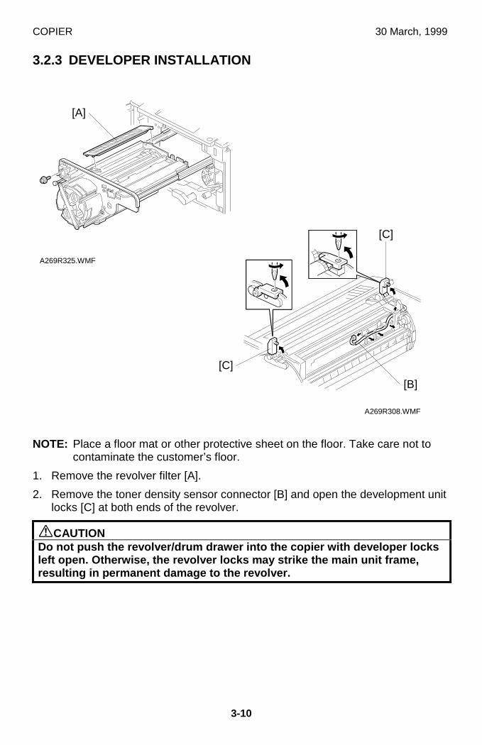
COPIER 30 March, 1999
3-10
3.2.3 DEVELOPER INSTALLATION
NOTE: Place a floor mat or other protective sheet on the floor. Take care not tocontaminate the customer’s floor.
1. Remove the revolver filter [A].
2. Remove the toner density sensor connector [B] and open the development unitlocks [C] at both ends of the revolver.
øCAUTIONDo not push the revolver/drum drawer into the copier with developer locksleft open. Otherwise, the revolver locks may strike the main unit frame,resulting in permanent damage to the revolver.
A269R308.WMF
A269R325.WMF
[C]
[C]
[B]
[A]
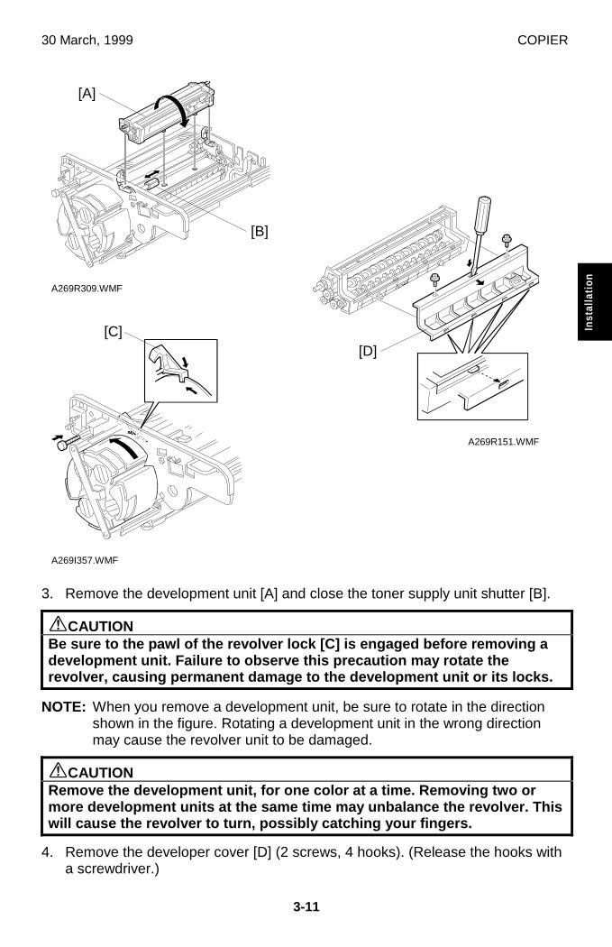
30 March, 1999 COPIER
3-11
Inst
alla
tion
3. Remove the development unit [A] and close the toner supply unit shutter [B].
øCAUTIONBe sure to the pawl of the revolver lock [C] is engaged before removing adevelopment unit. Failure to observe this precaution may rotate therevolver, causing permanent damage to the development unit or its locks.
NOTE: When you remove a development unit, be sure to rotate in the directionshown in the figure. Rotating a development unit in the wrong directionmay cause the revolver unit to be damaged.
øCAUTIONRemove the development unit, for one color at a time. Removing two ormore development units at the same time may unbalance the revolver. Thiswill cause the revolver to turn, possibly catching your fingers.
4. Remove the developer cover [D] (2 screws, 4 hooks). (Release the hooks witha screwdriver.)
A269R309.WMF
A269R151.WMF
A269I357.WMF
[A]
[D]
[B]
[C]
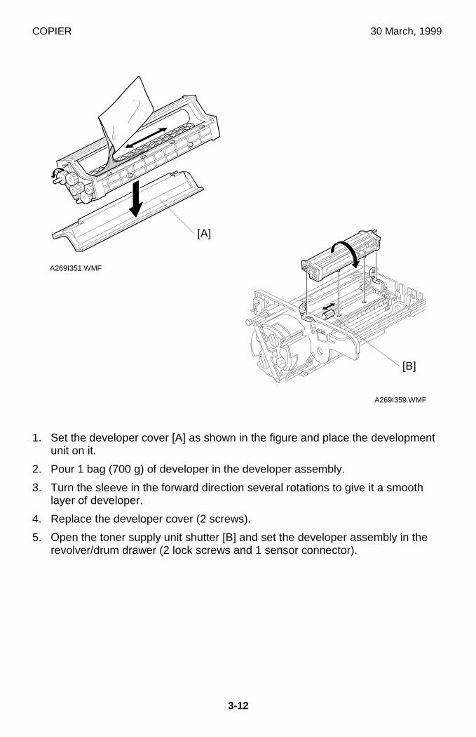
COPIER 30 March, 1999
3-12
1. Set the developer cover [A] as shown in the figure and place the developmentunit on it.
2. Pour 1 bag (700 g) of developer in the developer assembly.
3. Turn the sleeve in the forward direction several rotations to give it a smoothlayer of developer.
4. Replace the developer cover (2 screws).
5. Open the toner supply unit shutter [B] and set the developer assembly in therevolver/drum drawer (2 lock screws and 1 sensor connector).
A269I351.WMF
A269I359.WMF
[A]
[B]
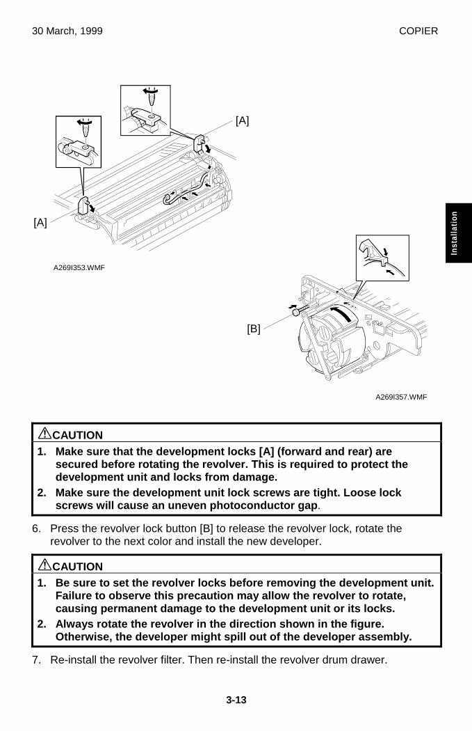
30 March, 1999 COPIER
3-13
Inst
alla
tion
øCAUTION1. Make sure that the development locks [A] (forward and rear) are
secured before rotating the revolver. This is required to protect thedevelopment unit and locks from damage.
2. Make sure the development unit lock screws are tight. Loose lockscrews will cause an uneven photoconductor gap .
6. Press the revolver lock button [B] to release the revolver lock, rotate therevolver to the next color and install the new developer.
øCAUTION1. Be sure to set the revolver locks before removing the development unit.
Failure to observe this precaution may allow the revolver to rotate,causing permanent damage to the development unit or its locks.
2. Always rotate the revolver in the direction shown in the figure.Otherwise, the developer might spill out of the developer assembly.
7. Re-install the revolver filter. Then re-install the revolver drum drawer.
A269I353.WMF
A269I357.WMF
[A]
[B]
[A]
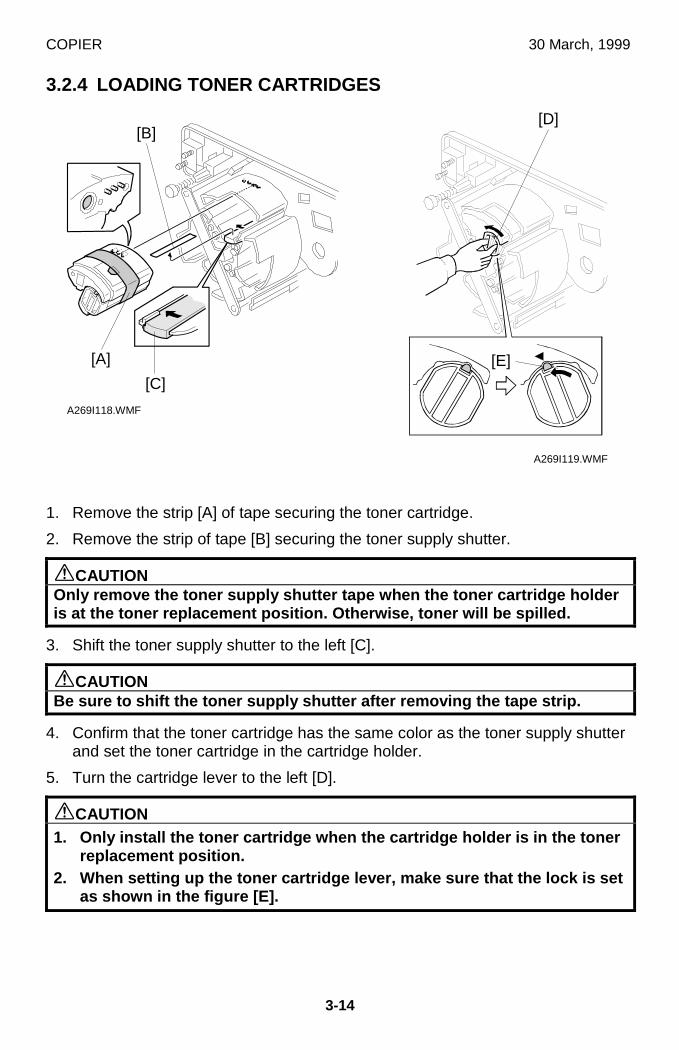
COPIER 30 March, 1999
3-14
3.2.4 LOADING TONER CARTRIDGES
1. Remove the strip [A] of tape securing the toner cartridge.
2. Remove the strip of tape [B] securing the toner supply shutter.
øCAUTIONOnly remove the toner supply shutter tape when the toner cartridge holderis at the toner replacement position. Otherwise, toner will be spilled.
3. Shift the toner supply shutter to the left [C].
øCAUTIONBe sure to shift the toner supply shutter after removing the tape strip.
4. Confirm that the toner cartridge has the same color as the toner supply shutterand set the toner cartridge in the cartridge holder.
5. Turn the cartridge lever to the left [D].
øCAUTION1. Only install the toner cartridge when the cartridge holder is in the toner
replacement position.2. When setting up the toner cartridge lever, make sure that the lock is set
as shown in the figure [E].
A269I119.WMF
A269I118.WMF
[B]
[C]
[A]
[D]
[E]
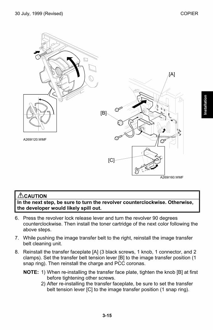
30 July, 1999 (Revised) COPIER
3-15
Inst
alla
tio
n
!CAUTIONIn the next step, be sure to turn the revolver counterclockwise. Otherwise,the developer would likely spill out.
6. Press the revolver lock release lever and turn the revolver 90 degreescounterclockwise. Then install the toner cartridge of the next color following theabove steps.
7. While pushing the image transfer belt to the right, reinstall the image transferbelt cleaning unit.
8. Reinstall the transfer faceplate [A] (3 black screws, 1 knob, 1 connector, and 2clamps). Set the transfer belt tension lever [B] to the image transfer position (1snap ring). Then reinstall the charge and PCC coronas.
NOTE: 1) When re-installing the transfer face plate, tighten the knob [B] at firstbefore tightening other screws.
2) After re-installing the transfer faceplate, be sure to set the transferbelt tension lever [C] to the image transfer position (1 snap ring).
A269I120.WMF
A269I160.WMF
[A]
[B]
[C]
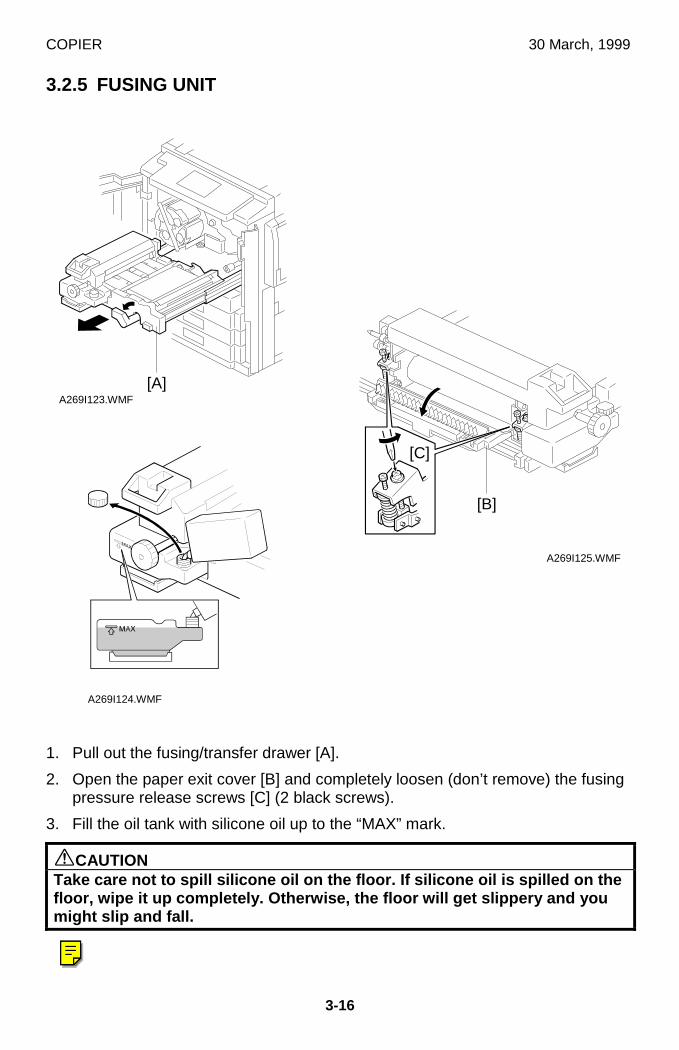
COPIER 30 March, 1999
3-16
3.2.5 FUSING UNIT
1. Pull out the fusing/transfer drawer [A].
2. Open the paper exit cover [B] and completely loosen (don’t remove) the fusingpressure release screws [C] (2 black screws).
3. Fill the oil tank with silicone oil up to the “MAX” mark.
øCAUTIONTake care not to spill silicone oil on the floor. If silicone oil is spilled on thefloor, wipe it up completely. Otherwise, the floor will get slippery and youmight slip and fall.
A269I125.WMF
A269I123.WMF
A269I124.WMF
[C]
[A]
[B]
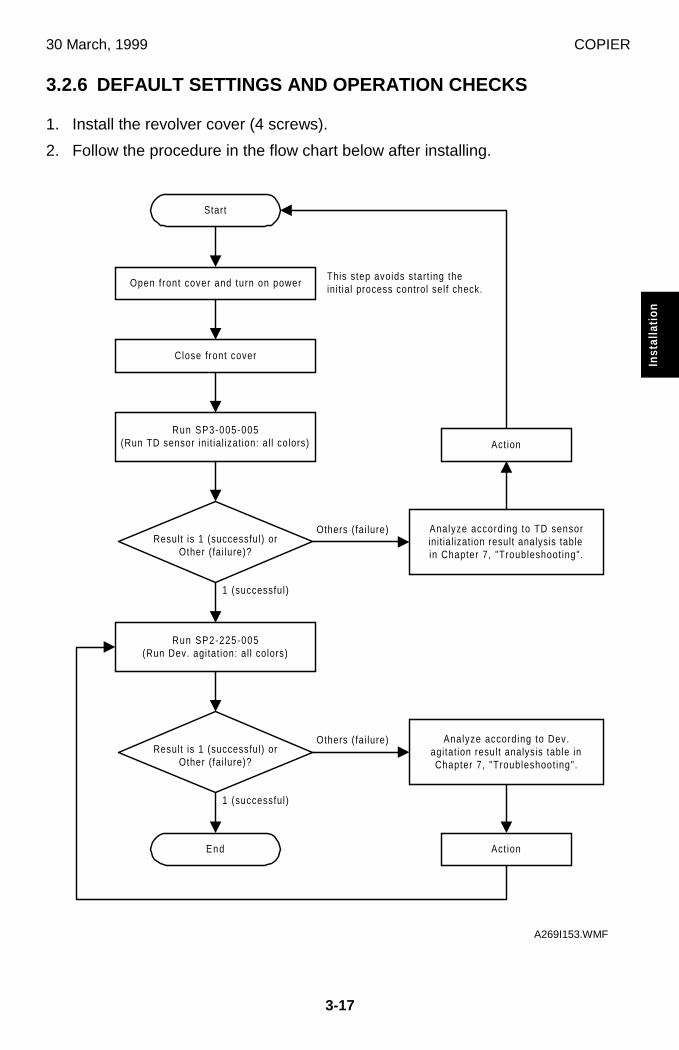
30 March, 1999 COPIER
3-17
Inst
alla
tion
3.2.6 DEFAULT SETTINGS AND OPERATION CHECKS
1. Install the revolver cover (4 screws).
2. Follow the procedure in the flow chart below after installing.
1 (successful)
Start
Result is 1 (successful) orOther (fai lure)?
Open front cover and turn on power
Close front cover
Run SP3-005-005(Run TD sensor ini t ial izat ion: al l colors)
Run SP2-225-005(Run Dev. agitat ion: al l colors)
Result is 1 (successful) orOther (fai lure)?
End
Analyze according to TD sensorinit ial ization result analysis tablein Chapter 7, "Troubleshoot ing".
Act ion
Analyze according to Dev.agitat ion result analysis table inChapter 7, "Troubleshoot ing".
Act ion
Others (fai lure)
1 (successful)
Others (fai lure)
This step avoids start ing theinit ial process control self check.
A269I153.WMF
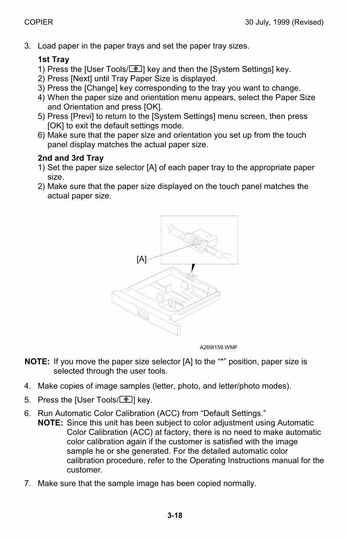
COPIER 30 July, 1999 (Revised)
3-18
3. Load paper in the paper trays and set the paper tray sizes.
1st Tray1) Press the [User Tools/!] key and then the [System Settings] key.2) Press [Next] until Tray Paper Size is displayed.3) Press the [Change] key corresponding to the tray you want to change.4) When the paper size and orientation menu appears, select the Paper Size
and Orientation and press [OK].5) Press [Previ] to return to the [System Settings] menu screen, then press
[OK] to exit the default settings mode.6) Make sure that the paper size and orientation you set up from the touch
panel display matches the actual paper size.
2nd and 3rd Tray1) Set the paper size selector [A] of each paper tray to the appropriate paper
size.2) Make sure that the paper size displayed on the touch panel matches the
actual paper size.
NOTE: If you move the paper size selector [A] to the “*” position, paper size isselected through the user tools.
4. Make copies of image samples (letter, photo, and letter/photo modes).
5. Press the [User Tools/!] key.
6. Run Automatic Color Calibration (ACC) from “Default Settings.”NOTE: Since this unit has been subject to color adjustment using Automatic
Color Calibration (ACC) at factory, there is no need to make automaticcolor calibration again if the customer is satisfied with the imagesample he or she generated. For the detailed automatic colorcalibration procedure, refer to the Operating Instructions manual for thecustomer.
7. Make sure that the sample image has been copied normally.
A269I159.WMF
[A]
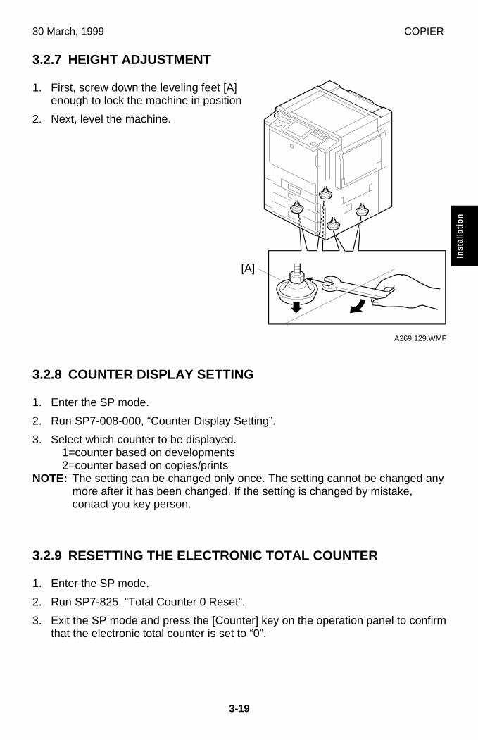
30 March, 1999 COPIER
3-19
Inst
alla
tion
3.2.7 HEIGHT ADJUSTMENT
1. First, screw down the leveling feet [A]enough to lock the machine in position
2. Next, level the machine.
3.2.8 COUNTER DISPLAY SETTING
1. Enter the SP mode.
2. Run SP7-008-000, “Counter Display Setting”.
3. Select which counter to be displayed. 1=counter based on developments 2=counter based on copies/prints
NOTE: The setting can be changed only once. The setting cannot be changed anymore after it has been changed. If the setting is changed by mistake,contact you key person.
3.2.9 RESETTING THE ELECTRONIC TOTAL COUNTER
1. Enter the SP mode.
2. Run SP7-825, “Total Counter 0 Reset”.
3. Exit the SP mode and press the [Counter] key on the operation panel to confirmthat the electronic total counter is set to “0”.
A269I129.WMF
[A]
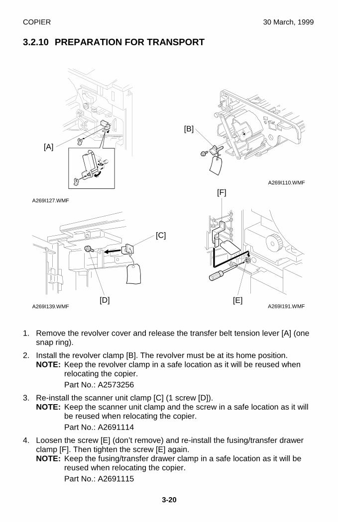
COPIER 30 March, 1999
3-20
3.2.10 PREPARATION FOR TRANSPORT
1. Remove the revolver cover and release the transfer belt tension lever [A] (onesnap ring).
2. Install the revolver clamp [B]. The revolver must be at its home position.NOTE: Keep the revolver clamp in a safe location as it will be reused when
relocating the copier.Part No.: A2573256
3. Re-install the scanner unit clamp [C] (1 screw [D]).NOTE: Keep the scanner unit clamp and the screw in a safe location as it will
be reused when relocating the copier.Part No.: A2691114
4. Loosen the screw [E] (don’t remove) and re-install the fusing/transfer drawerclamp [F]. Then tighten the screw [E] again.NOTE: Keep the fusing/transfer drawer clamp in a safe location as it will be
reused when relocating the copier.Part No.: A2691115
A269I127.WMF
A269I110.WMF
A269I191.WMFA269I139.WMF
[A]
[B]
[D]
[C]
[E]
[F]
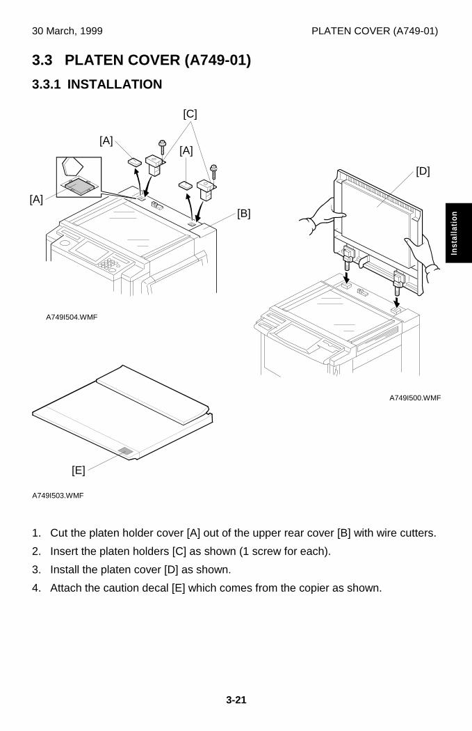
30 March, 1999 PLATEN COVER (A749-01)
3-21
Inst
alla
tion
3.3 PLATEN COVER (A749-01)
3.3.1 INSTALLATION
1. Cut the platen holder cover [A] out of the upper rear cover [B] with wire cutters.
2. Insert the platen holders [C] as shown (1 screw for each).
3. Install the platen cover [D] as shown.
4. Attach the caution decal [E] which comes from the copier as shown.
A749I500.WMF
A749I504.WMF
A749I503.WMF
[D]
[E]
[C]
[A][B]
[A][A]

ARDF (A663) 30 March, 1999
3-22
3.4 ARDF (A663)
3.4.1 ACCESSORY CHECK
Check the quantity and condition of the accessories in the box with the followinglist:
Description Q’ty
1. New equipment Condition Report ......................................... 1
2. Installation Procedure ........................................................... 1
3. Stud Screw............................................................................ 1
4. Philips Screw with Flat Washer - M4 x 10 ............................. 1
5. Sponge Retainer ................................................................... 1
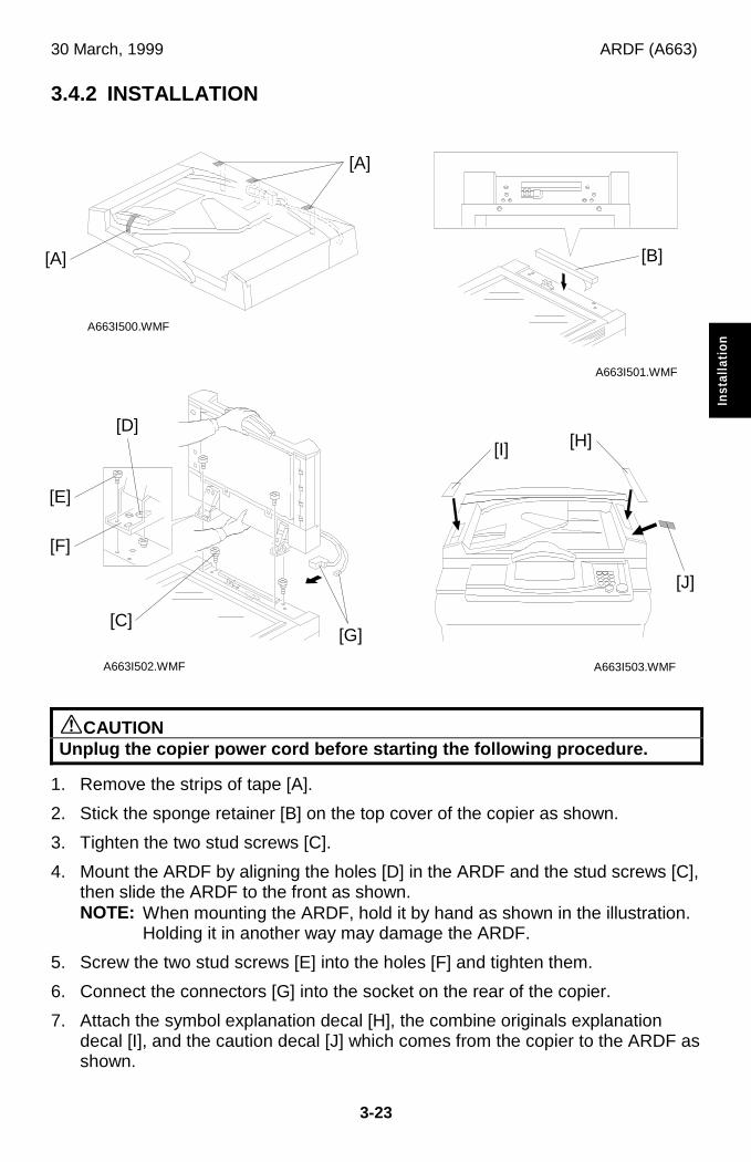
30 March, 1999 ARDF (A663)
3-23
Inst
alla
tion
3.4.2 INSTALLATION
øCAUTIONUnplug the copier power cord before starting the following procedure.
1. Remove the strips of tape [A].
2. Stick the sponge retainer [B] on the top cover of the copier as shown.
3. Tighten the two stud screws [C].
4. Mount the ARDF by aligning the holes [D] in the ARDF and the stud screws [C],then slide the ARDF to the front as shown.NOTE: When mounting the ARDF, hold it by hand as shown in the illustration.
Holding it in another way may damage the ARDF.
5. Screw the two stud screws [E] into the holes [F] and tighten them.
6. Connect the connectors [G] into the socket on the rear of the copier.
7. Attach the symbol explanation decal [H], the combine originals explanationdecal [I], and the caution decal [J] which comes from the copier to the ARDF asshown.
A663I501.WMF
A663I500.WMF
A663I502.WMF A663I503.WMF
[A]
[A]
[B]
[E]
[D][I]
[J]
[F]
[C][G]
[H]
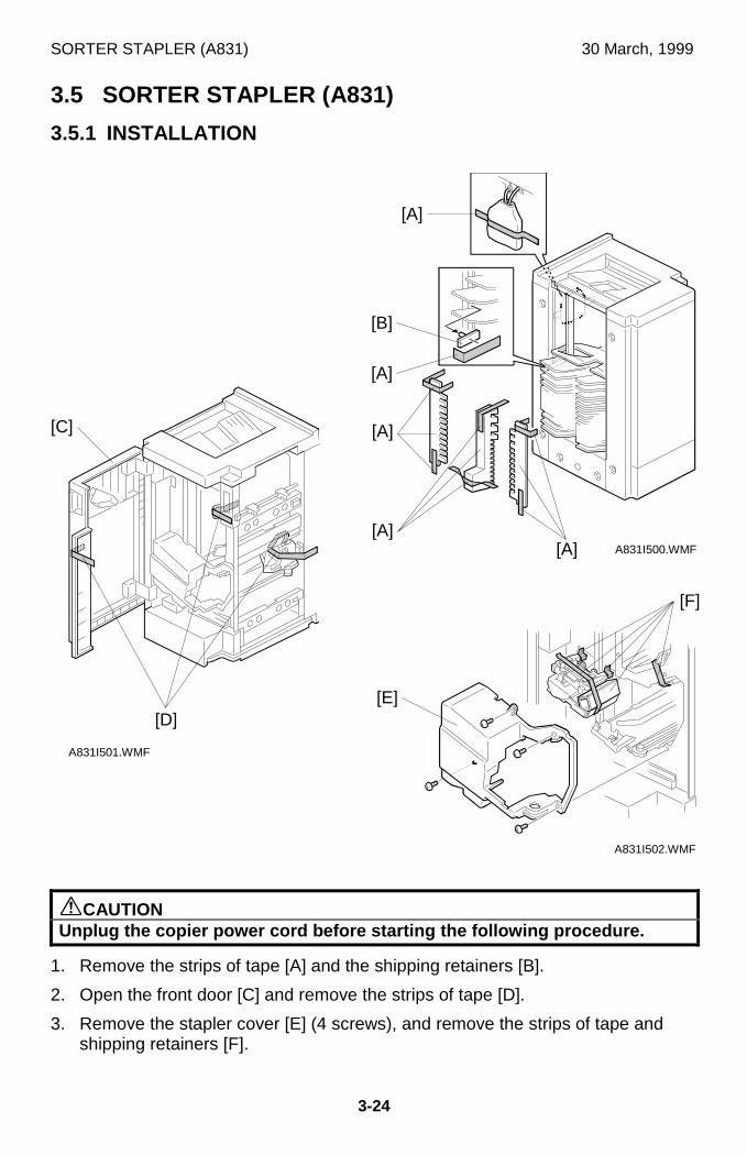
SORTER STAPLER (A831) 30 March, 1999
3-24
3.5 SORTER STAPLER (A831)
3.5.1 INSTALLATION
øCAUTIONUnplug the copier power cord before starting the following procedure.
1. Remove the strips of tape [A] and the shipping retainers [B].
2. Open the front door [C] and remove the strips of tape [D].
3. Remove the stapler cover [E] (4 screws), and remove the strips of tape andshipping retainers [F].
A831I501.WMF
A831I500.WMF
A831I502.WMF
[D]
[C]
[F]
[E]
[A][A]
[A]
[B]
[A]
[A]
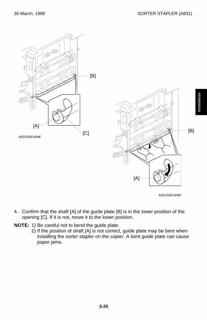
30 March, 1999 SORTER STAPLER (A831)
3-25
Inst
alla
tion
4. Confirm that the shaft [A] of the guide plate [B] is in the lower position of theopening [C]. If it is not, move it to the lower position.
NOTE: 1) Be careful not to bend the guide plate.2) If the position of shaft [A] is not correct, guide plate may be bent when
installing the sorter stapler on the copier. A bent guide plate can causepaper jams.
A831I508.WMF
A831I509.WMF
[B]
[A]
[C]
[A][B]
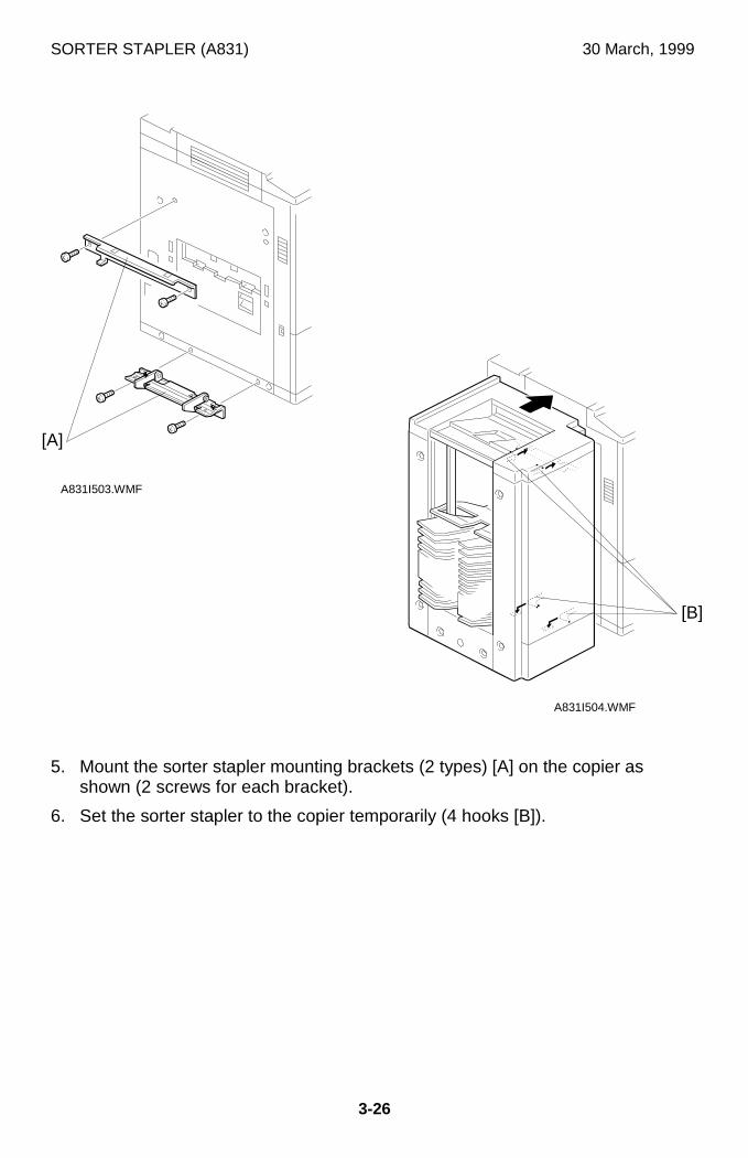
SORTER STAPLER (A831) 30 March, 1999
3-26
5. Mount the sorter stapler mounting brackets (2 types) [A] on the copier asshown (2 screws for each bracket).
6. Set the sorter stapler to the copier temporarily (4 hooks [B]).
A831I503.WMF
A831I504.WMF
[A]
[B]
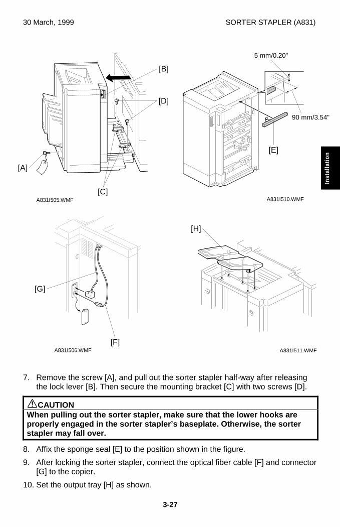
30 March, 1999 SORTER STAPLER (A831)
3-27
Inst
alla
tion
7. Remove the screw [A], and pull out the sorter stapler half-way after releasingthe lock lever [B]. Then secure the mounting bracket [C] with two screws [D].
øCAUTIONWhen pulling out the sorter stapler, make sure that the lower hooks areproperly engaged in the sorter stapler’s baseplate. Otherwise, the sorterstapler may fall over.
8. Affix the sponge seal [E] to the position shown in the figure.
9. After locking the sorter stapler, connect the optical fiber cable [F] and connector[G] to the copier.
10. Set the output tray [H] as shown.
A831I505.WMF
A831I506.WMF
A831I510.WMF
A831I511.WMF
[D]
[A]
[G]
[C]
[F]
[B]
[E]
90 mm/3.54"
5 mm/0.20"
[H]
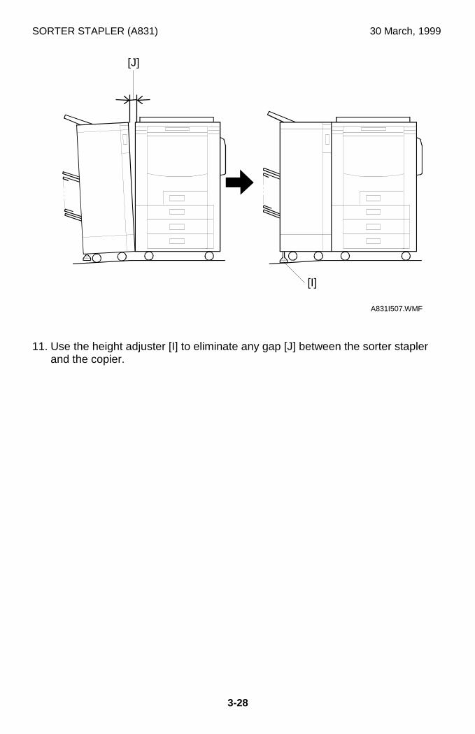
SORTER STAPLER (A831) 30 March, 1999
3-28
11. Use the height adjuster [I] to eliminate any gap [J] between the sorter staplerand the copier.
A831I507.WMF
[I]
[J]
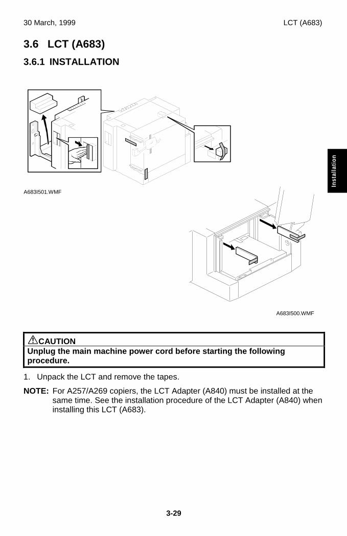
30 March, 1999 LCT (A683)
3-29
Inst
alla
tion
3.6 LCT (A683)
3.6.1 INSTALLATION
øCAUTIONUnplug the main machine power cord before starting the followingprocedure.
1. Unpack the LCT and remove the tapes.
NOTE: For A257/A269 copiers, the LCT Adapter (A840) must be installed at thesame time. See the installation procedure of the LCT Adapter (A840) wheninstalling this LCT (A683).
A683I501.WMF
A683I500.WMF
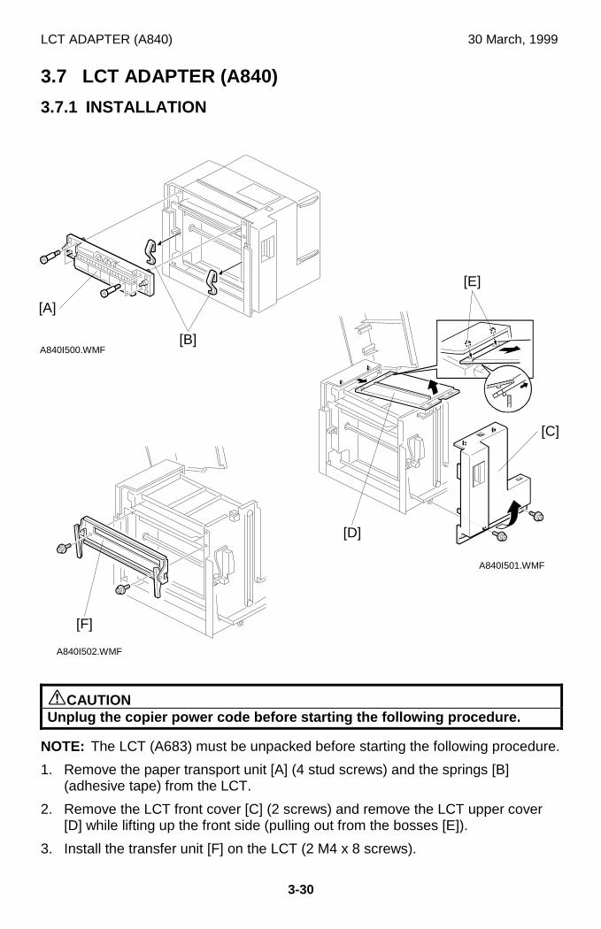
LCT ADAPTER (A840) 30 March, 1999
3-30
3.7 LCT ADAPTER (A840)
3.7.1 INSTALLATION
øCAUTIONUnplug the copier power code before starting the following procedure.
NOTE: The LCT (A683) must be unpacked before starting the following procedure.
1. Remove the paper transport unit [A] (4 stud screws) and the springs [B](adhesive tape) from the LCT.
2. Remove the LCT front cover [C] (2 screws) and remove the LCT upper cover[D] while lifting up the front side (pulling out from the bosses [E]).
3. Install the transfer unit [F] on the LCT (2 M4 x 8 screws).
A840I501.WMF
A840I502.WMF
A840I500.WMF
[E]
[C]
[F]
[D]
[B]
[A]
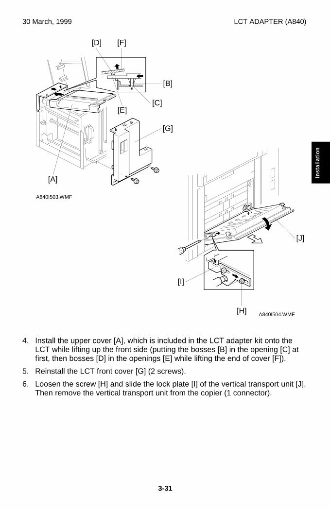
30 March, 1999 LCT ADAPTER (A840)
3-31
Inst
alla
tion
4. Install the upper cover [A], which is included in the LCT adapter kit onto theLCT while lifting up the front side (putting the bosses [B] in the opening [C] atfirst, then bosses [D] in the openings [E] while lifting the end of cover [F]).
5. Reinstall the LCT front cover [G] (2 screws).
6. Loosen the screw [H] and slide the lock plate [I] of the vertical transport unit [J].Then remove the vertical transport unit from the copier (1 connector).
A840I503.WMF
A840I504.WMF
[E]
[G]
[I]
[F]
[A]
[H]
[J]
[B]
[C]
[D]
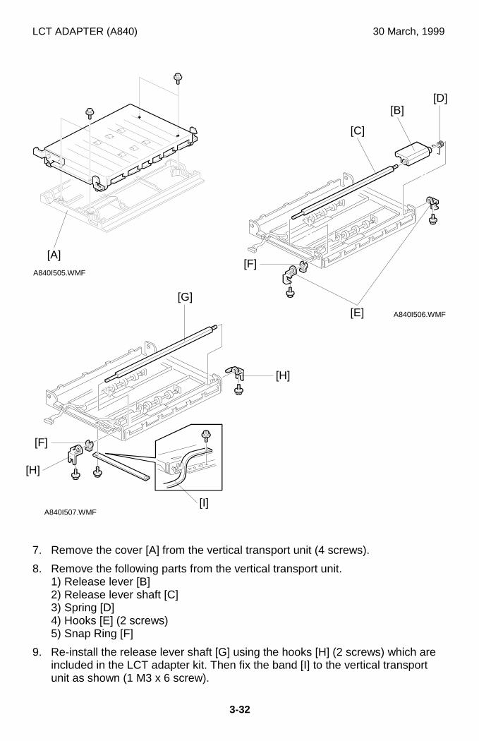
LCT ADAPTER (A840) 30 March, 1999
3-32
7. Remove the cover [A] from the vertical transport unit (4 screws).
8. Remove the following parts from the vertical transport unit.1) Release lever [B]2) Release lever shaft [C]3) Spring [D]4) Hooks [E] (2 screws)5) Snap Ring [F]
9. Re-install the release lever shaft [G] using the hooks [H] (2 screws) which areincluded in the LCT adapter kit. Then fix the band [I] to the vertical transportunit as shown (1 M3 x 6 screw).
A840I505.WMF
A840I506.WMF
A840I507.WMF
[A]
[E]
[B]
[C]
[D]
[G]
[F]
[I]
[H]
[H]
[F]
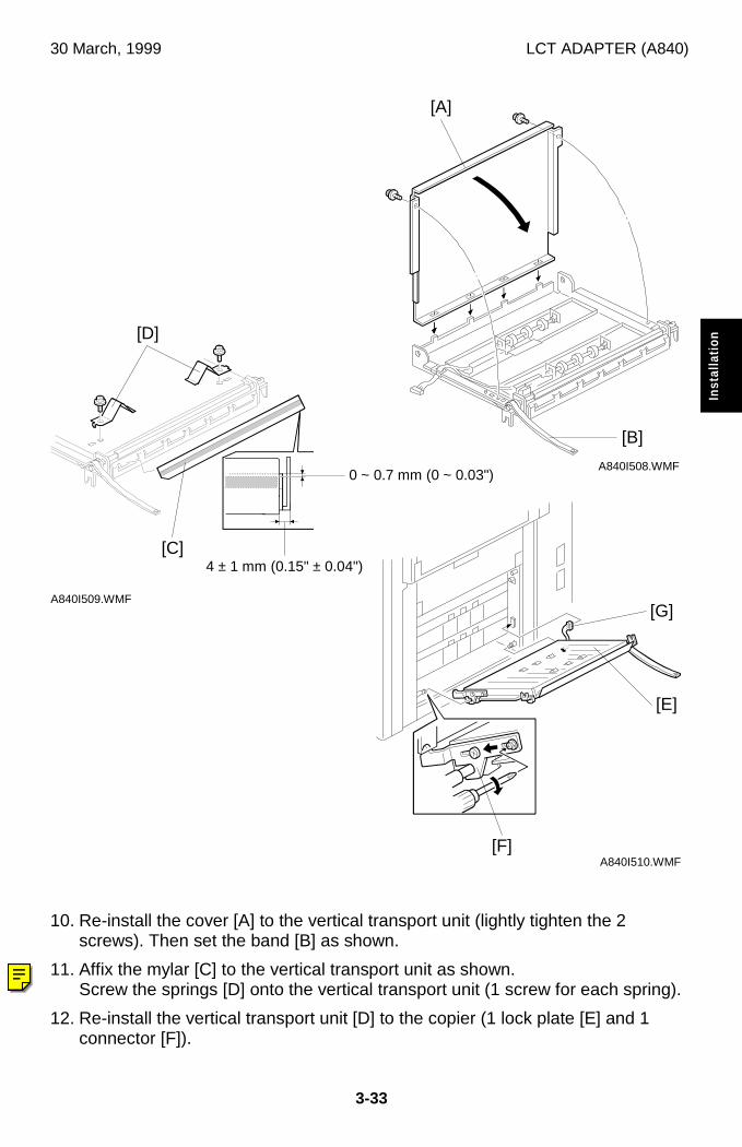
30 March, 1999 LCT ADAPTER (A840)
3-33
Inst
alla
tion
10. Re-install the cover [A] to the vertical transport unit (lightly tighten the 2screws). Then set the band [B] as shown.
11. Affix the mylar [C] to the vertical transport unit as shown.Screw the springs [D] onto the vertical transport unit (1 screw for each spring).
12. Re-install the vertical transport unit [D] to the copier (1 lock plate [E] and 1connector [F]).
A840I508.WMF
A840I510.WMF
A840I509.WMF
[B]
[G]
[E]
[A]
[F]
0 ~ 0.7 mm (0 ~ 0.03")
4 ± 1 mm (0.15" ± 0.04")
[D]
[C]
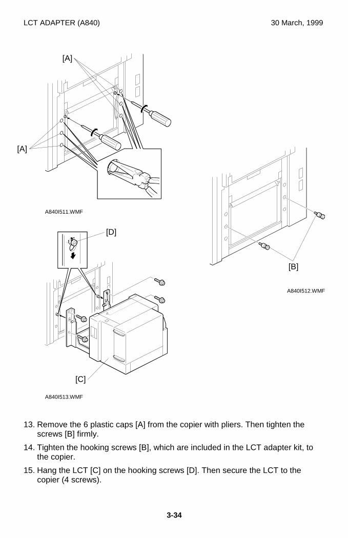
LCT ADAPTER (A840) 30 March, 1999
3-34
13. Remove the 6 plastic caps [A] from the copier with pliers. Then tighten thescrews [B] firmly.
14. Tighten the hooking screws [B], which are included in the LCT adapter kit, tothe copier.
15. Hang the LCT [C] on the hooking screws [D]. Then secure the LCT to thecopier (4 screws).
A840I511.WMF
A840I512.WMF
A840I513.WMF
[A]
[B]
[D]
[C]
[A]
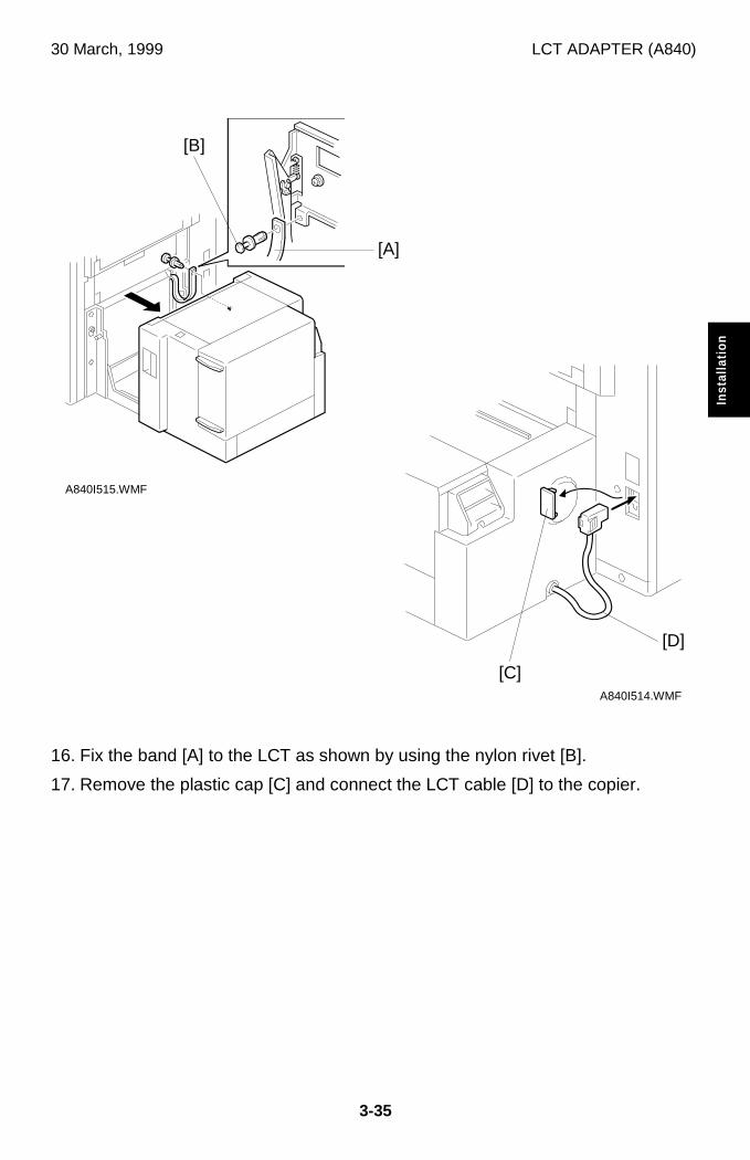
30 March, 1999 LCT ADAPTER (A840)
3-35
Inst
alla
tion
16. Fix the band [A] to the LCT as shown by using the nylon rivet [B].
17. Remove the plastic cap [C] and connect the LCT cable [D] to the copier.
A840I515.WMF
A840I514.WMF
[C]
[D]
[B]
[A]
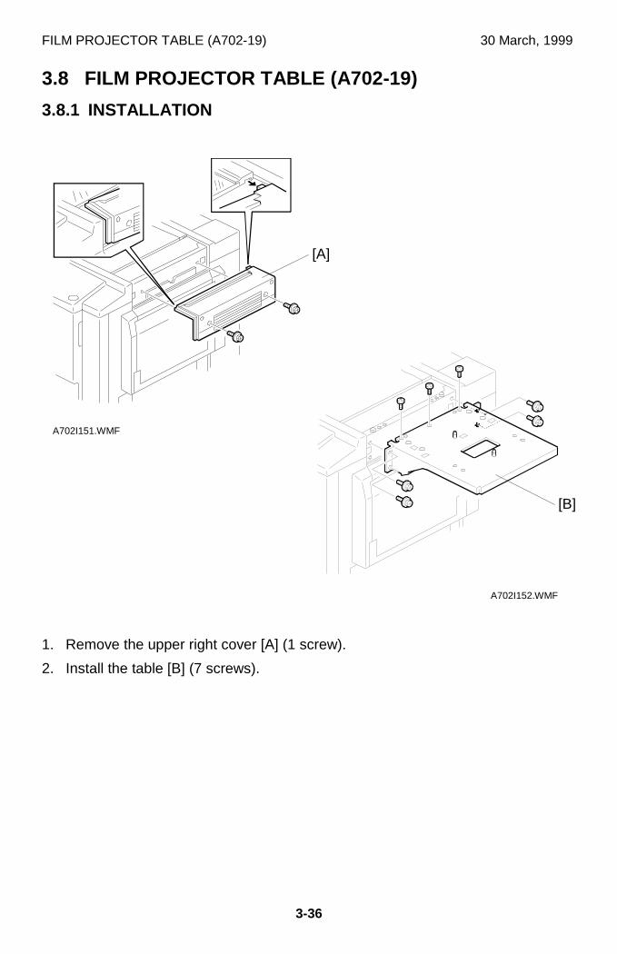
FILM PROJECTOR TABLE (A702-19) 30 March, 1999
3-36
3.8 FILM PROJECTOR TABLE (A702-19)
3.8.1 INSTALLATION
1. Remove the upper right cover [A] (1 screw).
2. Install the table [B] (7 screws).
A702I152.WMF
A702I151.WMF
[A]
[B]
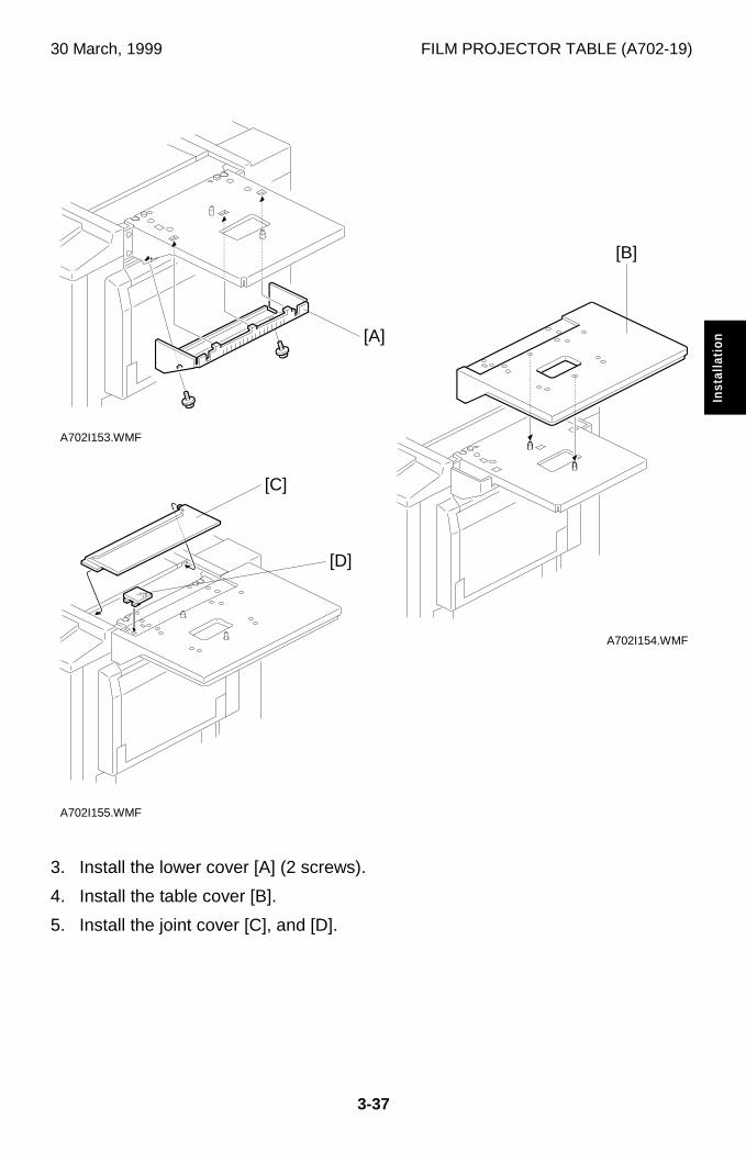
30 March, 1999 FILM PROJECTOR TABLE (A702-19)
3-37
Inst
alla
tion
3. Install the lower cover [A] (2 screws).
4. Install the table cover [B].
5. Install the joint cover [C], and [D].
A702I153.WMF
A702I154.WMF
A702I155.WMF
[A]
[B]
[C]
[D]
FILM PROJECTOR UNIT(A846) 30 March, 1999
3-38
3.9 FILM PROJECTOR UNIT(A846)
3.9.1 ACCESSORY CHECK
Check the quantity and condition of the accessories in the box with the followinglist:
Description Q’ty
1. Mirror Unit ............................................................................. 1
2. Power Cord ........................................................................... 1
3. Film Strip Holder ................................................................... 1
4. Slide Holder .......................................................................... 1
5. Glass Mount Holder .............................................................. 1
6. Base Film (FUJI, KODAK, AGFA)......................................... 3
7. Slide Mount ........................................................................... 1
8. Correction filter (P, N) ........................................................... 2
9. Blower Brush......................................................................... 1
10. Projection Lamp .................................................................... 1
11. Film Position Sheet ............................................................... 2
12. Philips Pan Head Screw - M3 x 12........................................ 5
13. Installation Procedure ........................................................... 1
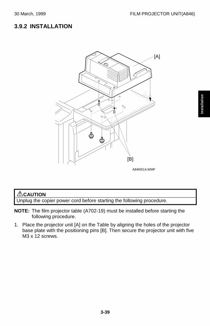
30 March, 1999 FILM PROJECTOR UNIT(A846)
3-39
Inst
alla
tion
3.9.2 INSTALLATION
øCAUTIONUnplug the copier power cord before starting the following procedure.
NOTE: The film projector table (A702-19) must be installed before starting thefollowing procedure.
1. Place the projector unit [A] on the Table by aligning the holes of the projectorbase plate with the positioning pins [B]. Then secure the projector unit with fiveM3 x 12 screws.
A846I514.WMF
[A]
[B]
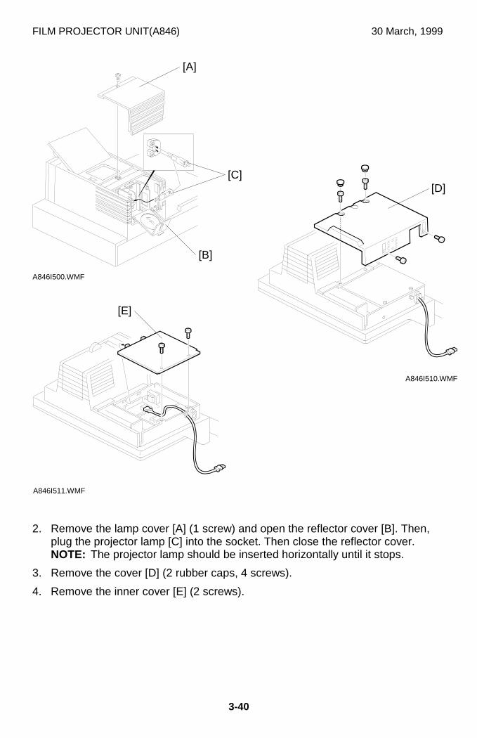
FILM PROJECTOR UNIT(A846) 30 March, 1999
3-40
2. Remove the lamp cover [A] (1 screw) and open the reflector cover [B]. Then,plug the projector lamp [C] into the socket. Then close the reflector cover.NOTE: The projector lamp should be inserted horizontally until it stops.
3. Remove the cover [D] (2 rubber caps, 4 screws).
4. Remove the inner cover [E] (2 screws).
A846I500.WMF
A846I511.WMF
A846I510.WMF
[C]
[A]
[B]
[E]
[D]
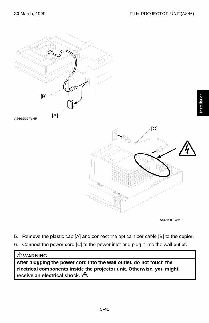
30 March, 1999 FILM PROJECTOR UNIT(A846)
3-41
Inst
alla
tion
5. Remove the plastic cap [A] and connect the optical fiber cable [B] to the copier.
6. Connect the power cord [C] to the power inlet and plug it into the wall outlet.
øWARNINGAfter plugging the power cord into the wall outlet, do not touch theelectrical components inside the projector unit. Otherwise, you mightreceive an electrical shock. õõõõ
A846I515.WMF
A846I501.WMF
[B]
[A]
[C]
õ
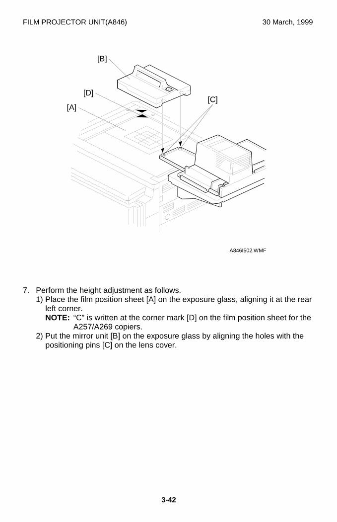
FILM PROJECTOR UNIT(A846) 30 March, 1999
3-42
7. Perform the height adjustment as follows.1) Place the film position sheet [A] on the exposure glass, aligning it at the rear
left corner.NOTE: “C” is written at the corner mark [D] on the film position sheet for the
A257/A269 copiers.2) Put the mirror unit [B] on the exposure glass by aligning the holes with the
positioning pins [C] on the lens cover.
A846I502.WMF
[C]
[B]
[A]
[D]
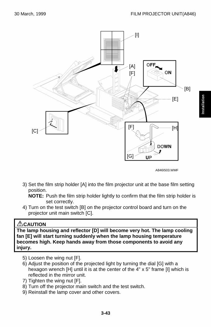
30 March, 1999 FILM PROJECTOR UNIT(A846)
3-43
Inst
alla
tion
3) Set the film strip holder [A] into the film projector unit at the base film settingposition.NOTE: Push the film strip holder lightly to confirm that the film strip holder is
set correctly.4) Turn on the test switch [B] on the projector control board and turn on the
projector unit main switch [C].
øCAUTIONThe lamp housing and reflector [D] will become very hot. The lamp coolingfan [E] will start turning suddenly when the lamp housing temperaturebecomes high. Keep hands away from those components to avoid anyinjury.
5) Loosen the wing nut [F].6) Adjust the position of the projected light by turning the dial [G] with a
hexagon wrench [H] until it is at the center of the 4" x 5" frame [I] which isreflected in the mirror unit.
7) Tighten the wing nut [F].8) Turn off the projector main switch and the test switch.9) Reinstall the lamp cover and other covers.
A846I503.WMF
[F]
[I]
[A]
[C]
[G]
[H]
[B]
[E]
[F]
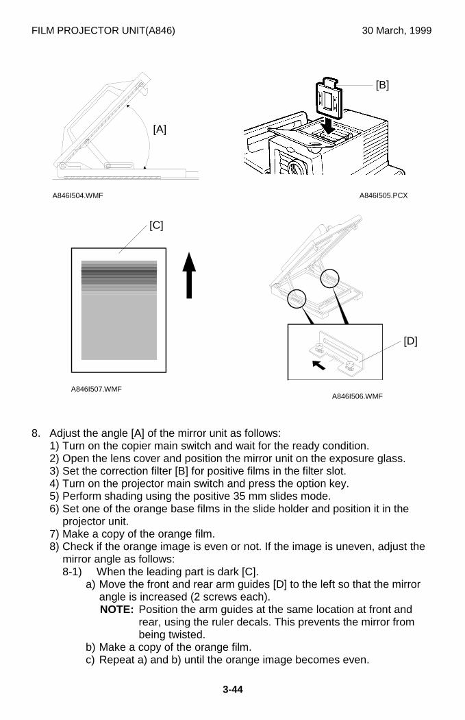
FILM PROJECTOR UNIT(A846) 30 March, 1999
3-44
8. Adjust the angle [A] of the mirror unit as follows:1) Turn on the copier main switch and wait for the ready condition.2) Open the lens cover and position the mirror unit on the exposure glass.3) Set the correction filter [B] for positive films in the filter slot.4) Turn on the projector main switch and press the option key.5) Perform shading using the positive 35 mm slides mode.6) Set one of the orange base films in the slide holder and position it in the
projector unit.7) Make a copy of the orange film.8) Check if the orange image is even or not. If the image is uneven, adjust the
mirror angle as follows:8-1) When the leading part is dark [C].
a) Move the front and rear arm guides [D] to the left so that the mirrorangle is increased (2 screws each).NOTE: Position the arm guides at the same location at front and
rear, using the ruler decals. This prevents the mirror frombeing twisted.
b) Make a copy of the orange film.c) Repeat a) and b) until the orange image becomes even.
A846I504.WMF A846I505.PCX
A846I507.WMFA846I506.WMF
[A]
[B]
[C]
[D]
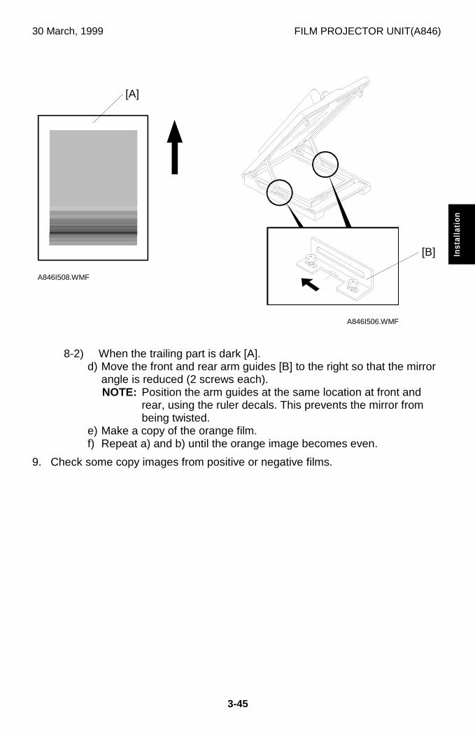
30 March, 1999 FILM PROJECTOR UNIT(A846)
3-45
Inst
alla
tion
8-2) When the trailing part is dark [A].d) Move the front and rear arm guides [B] to the right so that the mirror
angle is reduced (2 screws each).NOTE: Position the arm guides at the same location at front and
rear, using the ruler decals. This prevents the mirror frombeing twisted.
e) Make a copy of the orange film.f) Repeat a) and b) until the orange image becomes even.
9. Check some copy images from positive or negative films.
A846I508.WMF
A846I506.WMF
[A]
[B]
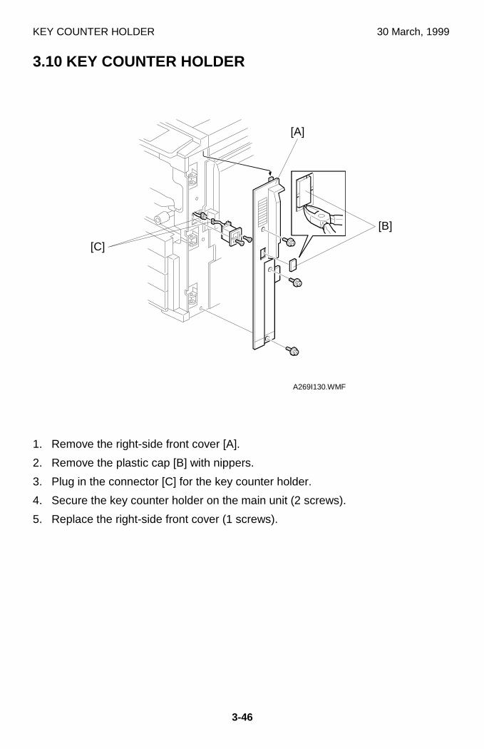
KEY COUNTER HOLDER 30 March, 1999
3-46
3.10 KEY COUNTER HOLDER
1. Remove the right-side front cover [A].
2. Remove the plastic cap [B] with nippers.
3. Plug in the connector [C] for the key counter holder.
4. Secure the key counter holder on the main unit (2 screws).
5. Replace the right-side front cover (1 screws).
A269I130.WMF
[A]
[C]
[B]
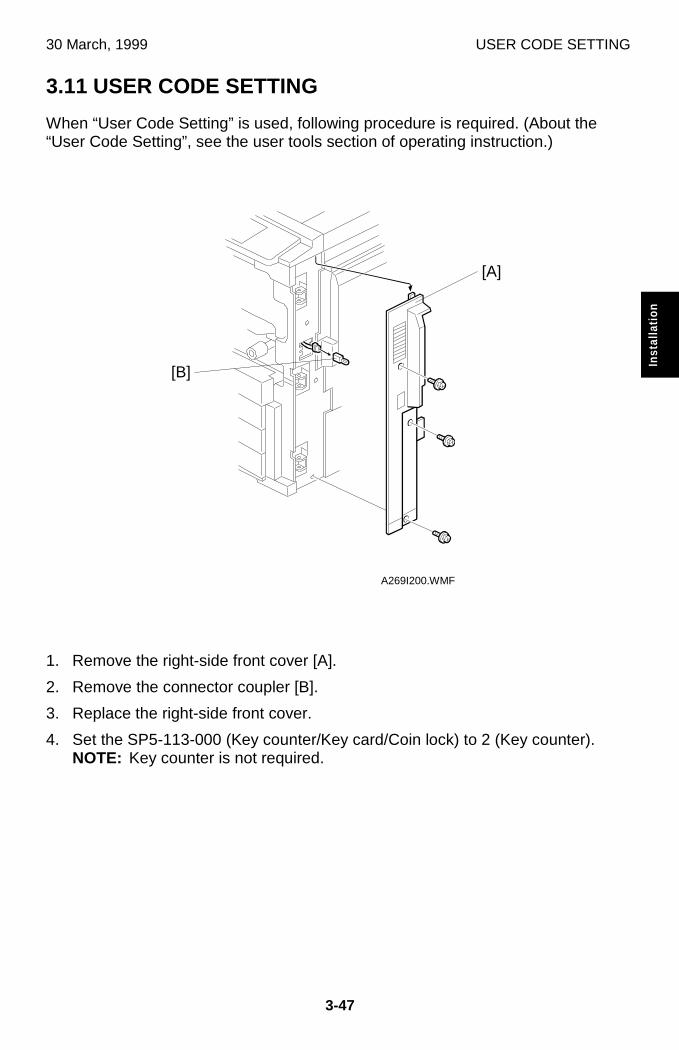
30 March, 1999 USER CODE SETTING
3-47
Inst
alla
tion
3.11 USER CODE SETTING
When “User Code Setting” is used, following procedure is required. (About the“User Code Setting”, see the user tools section of operating instruction.)
1. Remove the right-side front cover [A].
2. Remove the connector coupler [B].
3. Replace the right-side front cover.
4. Set the SP5-113-000 (Key counter/Key card/Coin lock) to 2 (Key counter).NOTE: Key counter is not required.
A269I200.WMF
[A]
[B]
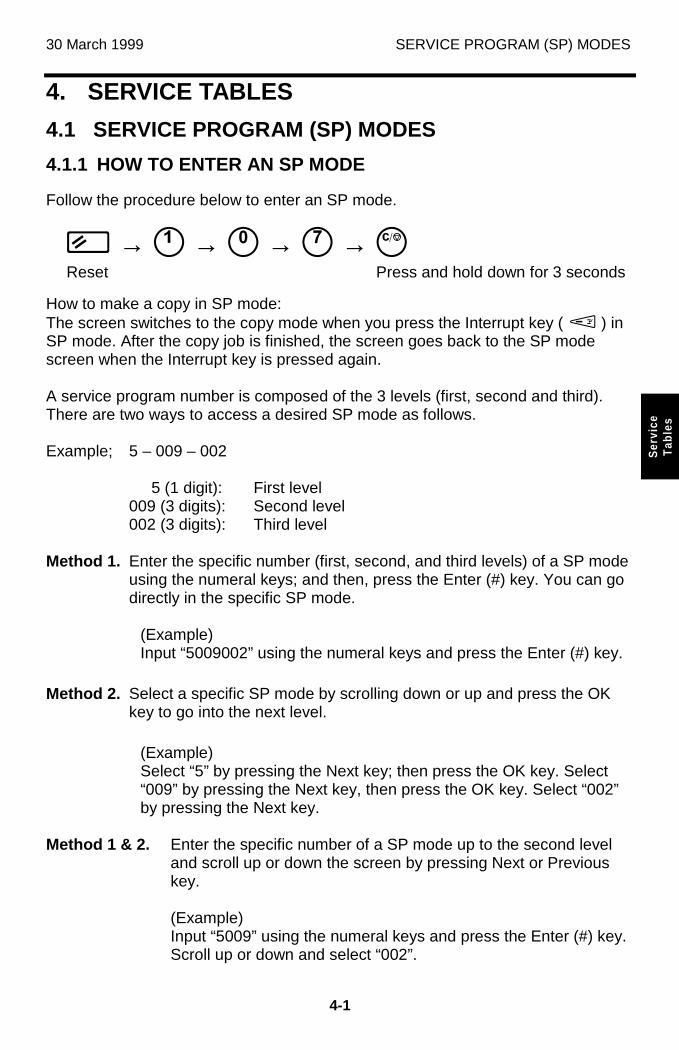
30 March 1999 SERVICE PROGRAM (SP) MODES
4-1
Ser
vice
Tab
les
4. SERVICE TABLES
4.1 SERVICE PROGRAM (SP) MODES
4.1.1 HOW TO ENTER AN SP MODE
Follow the procedure below to enter an SP mode.
ô → ò → ó → ì → EReset Press and hold down for 3 seconds
How to make a copy in SP mode:The screen switches to the copy mode when you press the Interrupt key ( M ) inSP mode. After the copy job is finished, the screen goes back to the SP modescreen when the Interrupt key is pressed again.
A service program number is composed of the 3 levels (first, second and third).There are two ways to access a desired SP mode as follows.
Example; 5 – 009 – 002
5 (1 digit): First level009 (3 digits): Second level002 (3 digits): Third level
Method 1. Enter the specific number (first, second, and third levels) of a SP modeusing the numeral keys; and then, press the Enter (#) key. You can godirectly in the specific SP mode.
(Example)Input “5009002” using the numeral keys and press the Enter (#) key.
Method 2. Select a specific SP mode by scrolling down or up and press the OKkey to go into the next level.
(Example)Select “5” by pressing the Next key; then press the OK key. Select“009” by pressing the Next key, then press the OK key. Select “002”by pressing the Next key.
Method 1 & 2. Enter the specific number of a SP mode up to the second leveland scroll up or down the screen by pressing Next or Previouskey.
(Example)Input “5009” using the numeral keys and press the Enter (#) key.Scroll up or down and select “002”.
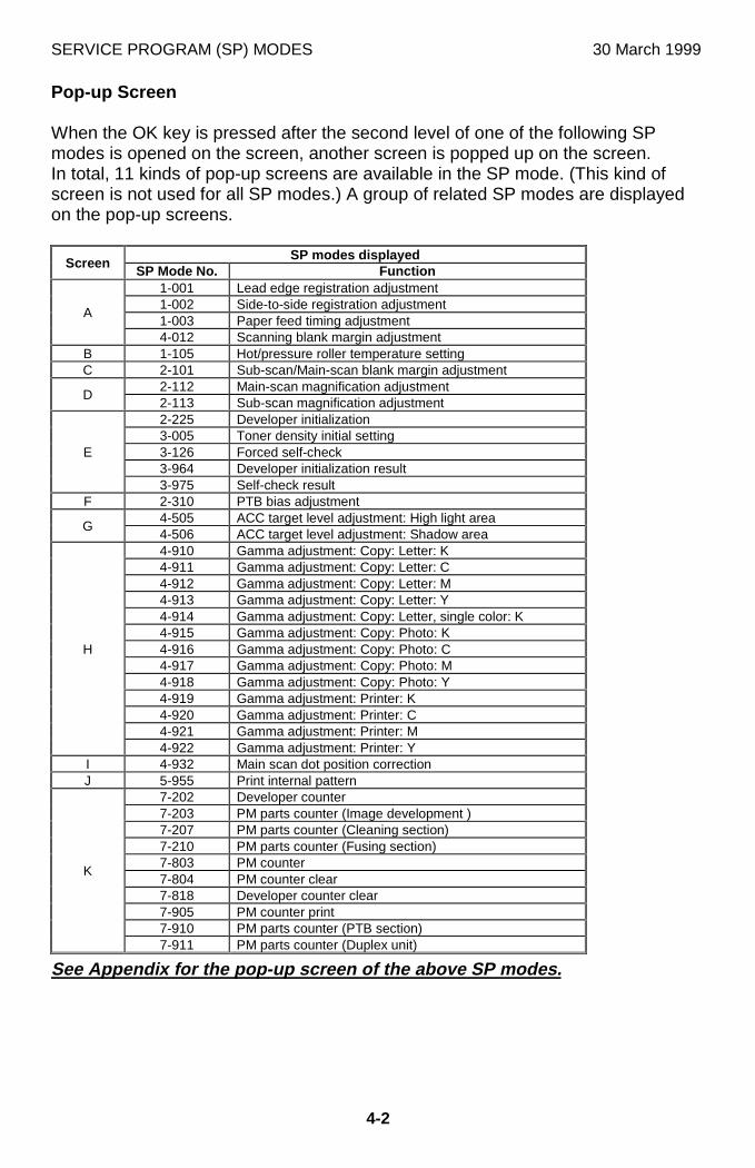
SERVICE PROGRAM (SP) MODES 30 March 1999
4-2
Pop-up Screen
When the OK key is pressed after the second level of one of the following SPmodes is opened on the screen, another screen is popped up on the screen.In total, 11 kinds of pop-up screens are available in the SP mode. (This kind ofscreen is not used for all SP modes.) A group of related SP modes are displayedon the pop-up screens.
SP modes displayedScreen
SP Mode No. Function1-001 Lead edge registration adjustment1-002 Side-to-side registration adjustment1-003 Paper feed timing adjustment
A
4-012 Scanning blank margin adjustmentB 1-105 Hot/pressure roller temperature settingC 2-101 Sub-scan/Main-scan blank margin adjustment
2-112 Main-scan magnification adjustmentD
2-113 Sub-scan magnification adjustment2-225 Developer initialization3-005 Toner density initial setting3-126 Forced self-check3-964 Developer initialization result
E
3-975 Self-check resultF 2-310 PTB bias adjustment
4-505 ACC target level adjustment: High light areaG
4-506 ACC target level adjustment: Shadow area4-910 Gamma adjustment: Copy: Letter: K4-911 Gamma adjustment: Copy: Letter: C4-912 Gamma adjustment: Copy: Letter: M4-913 Gamma adjustment: Copy: Letter: Y4-914 Gamma adjustment: Copy: Letter, single color: K4-915 Gamma adjustment: Copy: Photo: K4-916 Gamma adjustment: Copy: Photo: C4-917 Gamma adjustment: Copy: Photo: M4-918 Gamma adjustment: Copy: Photo: Y4-919 Gamma adjustment: Printer: K4-920 Gamma adjustment: Printer: C4-921 Gamma adjustment: Printer: M
H
4-922 Gamma adjustment: Printer: YI 4-932 Main scan dot position correctionJ 5-955 Print internal pattern
7-202 Developer counter7-203 PM parts counter (Image development )7-207 PM parts counter (Cleaning section)7-210 PM parts counter (Fusing section)7-803 PM counter7-804 PM counter clear7-818 Developer counter clear7-905 PM counter print7-910 PM parts counter (PTB section)
K
7-911 PM parts counter (Duplex unit)
See Appendix for the pop-up screen of the above SP modes.
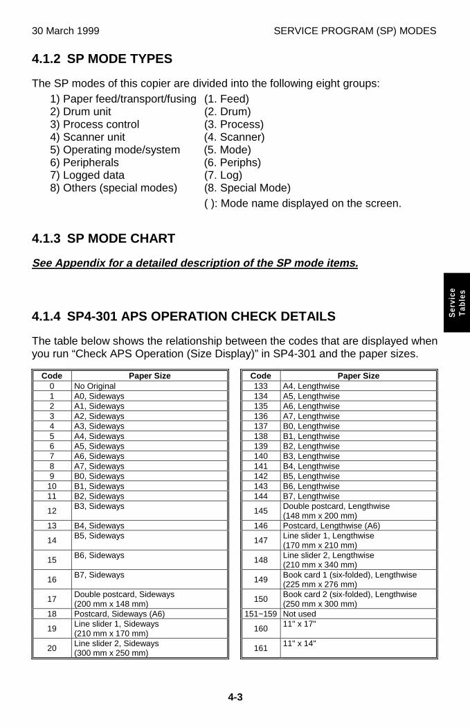
30 March 1999 SERVICE PROGRAM (SP) MODES
4-3
Ser
vice
Tab
les
4.1.2 SP MODE TYPES
The SP modes of this copier are divided into the following eight groups:1) Paper feed/transport/fusing (1. Feed)2) Drum unit (2. Drum)3) Process control (3. Process)4) Scanner unit (4. Scanner)5) Operating mode/system (5. Mode)6) Peripherals (6. Periphs)7) Logged data (7. Log)8) Others (special modes) (8. Special Mode)
( ): Mode name displayed on the screen.
4.1.3 SP MODE CHART
See Appendix for a detailed description of the SP mode items.
4.1.4 SP4-301 APS OPERATION CHECK DETAILS
The table below shows the relationship between the codes that are displayed whenyou run “Check APS Operation (Size Display)” in SP4-301 and the paper sizes.
Code Paper Size Code Paper Size0 No Original 133 A4, Lengthwise1 A0, Sideways 134 A5, Lengthwise2 A1, Sideways 135 A6, Lengthwise3 A2, Sideways 136 A7, Lengthwise4 A3, Sideways 137 B0, Lengthwise5 A4, Sideways 138 B1, Lengthwise6 A5, Sideways 139 B2, Lengthwise7 A6, Sideways 140 B3, Lengthwise8 A7, Sideways 141 B4, Lengthwise9 B0, Sideways 142 B5, Lengthwise
10 B1, Sideways 143 B6, Lengthwise11 B2, Sideways 144 B7, Lengthwise
12 B3, Sideways 145 Double postcard, Lengthwise(148 mm x 200 mm)
13 B4, Sideways 146 Postcard, Lengthwise (A6)
14 B5, Sideways 147 Line slider 1, Lengthwise(170 mm x 210 mm)
15 B6, Sideways 148 Line slider 2, Lengthwise(210 mm x 340 mm)
16 B7, Sideways 149 Book card 1 (six-folded), Lengthwise(225 mm x 276 mm)
17 Double postcard, Sideways(200 mm x 148 mm)
150 Book card 2 (six-folded), Lengthwise(250 mm x 300 mm)
18 Postcard, Sideways (A6) 151~159 Not used
19 Line slider 1, Sideways(210 mm x 170 mm)
160 11" x 17"
20 Line slider 2, Sideways(300 mm x 250 mm) 161 11" x 14"
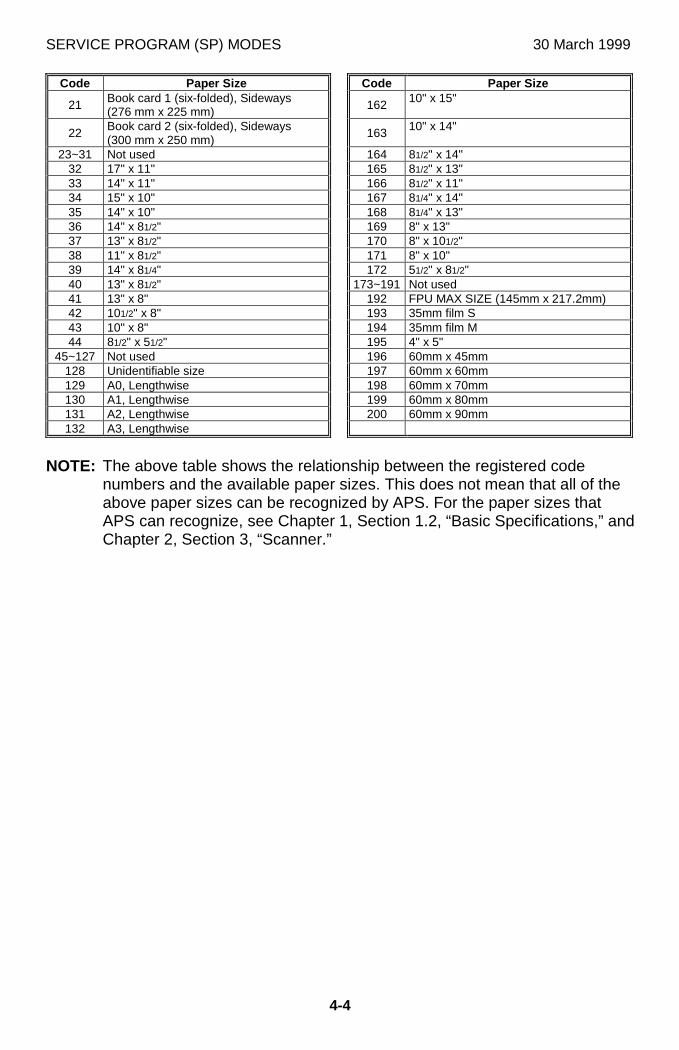
SERVICE PROGRAM (SP) MODES 30 March 1999
4-4
Code Paper Size Code Paper Size
21 Book card 1 (six-folded), Sideways(276 mm x 225 mm) 162 10" x 15"
22 Book card 2 (six-folded), Sideways(300 mm x 250 mm)
163 10" x 14"
23~31 Not used 164 81/2" x 14"32 17" x 11" 165 81/2" x 13"33 14" x 11" 166 81/2" x 11"34 15" x 10" 167 81/4" x 14"35 14" x 10" 168 81/4" x 13"36 14" x 81/2" 169 8" x 13"37 13" x 81/2" 170 8" x 101/2"38 11" x 81/2" 171 8" x 10"39 14" x 81/4" 172 51/2" x 81/2"40 13" x 81/2" 173~191 Not used41 13" x 8" 192 FPU MAX SIZE (145mm x 217.2mm)42 101/2" x 8" 193 35mm film S43 10" x 8" 194 35mm film M44 81/2" x 51/2" 195 4" x 5"
45~127 Not used 196 60mm x 45mm128 Unidentifiable size 197 60mm x 60mm129 A0, Lengthwise 198 60mm x 70mm130 A1, Lengthwise 199 60mm x 80mm131 A2, Lengthwise 200 60mm x 90mm132 A3, Lengthwise
NOTE: The above table shows the relationship between the registered codenumbers and the available paper sizes. This does not mean that all of theabove paper sizes can be recognized by APS. For the paper sizes thatAPS can recognize, see Chapter 1, Section 1.2, “Basic Specifications,” andChapter 2, Section 3, “Scanner.”
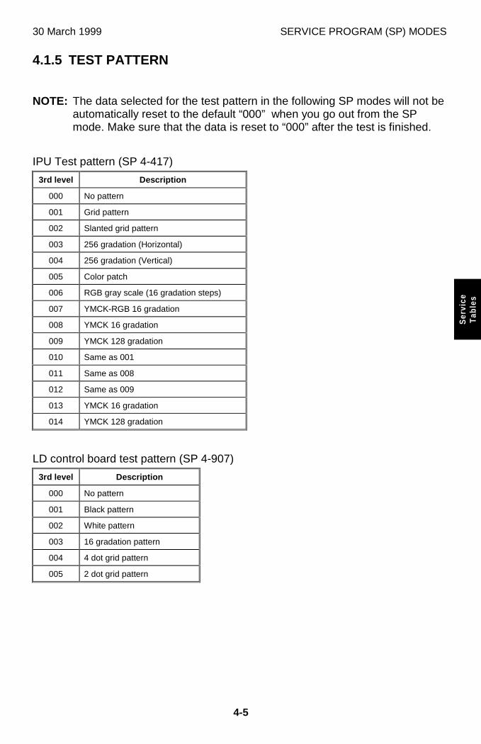
30 March 1999 SERVICE PROGRAM (SP) MODES
4-5
Ser
vice
Tab
les
4.1.5 TEST PATTERN
NOTE: The data selected for the test pattern in the following SP modes will not beautomatically reset to the default “000” when you go out from the SPmode. Make sure that the data is reset to “000” after the test is finished.
IPU Test pattern (SP 4-417)
3rd level Description
000 No pattern
001 Grid pattern
002 Slanted grid pattern
003 256 gradation (Horizontal)
004 256 gradation (Vertical)
005 Color patch
006 RGB gray scale (16 gradation steps)
007 YMCK-RGB 16 gradation
008 YMCK 16 gradation
009 YMCK 128 gradation
010 Same as 001
011 Same as 008
012 Same as 009
013 YMCK 16 gradation
014 YMCK 128 gradation
LD control board test pattern (SP 4-907)
3rd level Description
000 No pattern
001 Black pattern
002 White pattern
003 16 gradation pattern
004 4 dot grid pattern
005 2 dot grid pattern
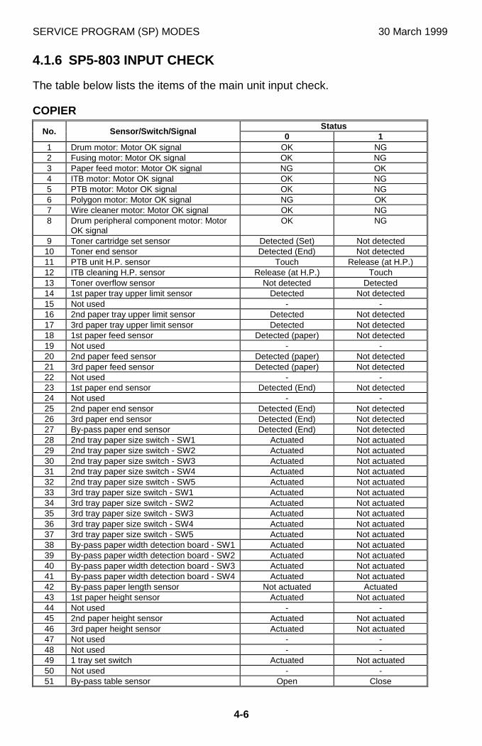
SERVICE PROGRAM (SP) MODES 30 March 1999
4-6
4.1.6 SP5-803 INPUT CHECK
The table below lists the items of the main unit input check.
COPIERStatus
No. Sensor/Switch/Signal0 1
1 Drum motor: Motor OK signal OK NG2 Fusing motor: Motor OK signal OK NG3 Paper feed motor: Motor OK signal NG OK4 ITB motor: Motor OK signal OK NG5 PTB motor: Motor OK signal OK NG6 Polygon motor: Motor OK signal NG OK7 Wire cleaner motor: Motor OK signal OK NG8 Drum peripheral component motor: Motor
OK signalOK NG
9 Toner cartridge set sensor Detected (Set) Not detected10 Toner end sensor Detected (End) Not detected11 PTB unit H.P. sensor Touch Release (at H.P.)12 ITB cleaning H.P. sensor Release (at H.P.) Touch13 Toner overflow sensor Not detected Detected14 1st paper tray upper limit sensor Detected Not detected15 Not used - -16 2nd paper tray upper limit sensor Detected Not detected17 3rd paper tray upper limit sensor Detected Not detected18 1st paper feed sensor Detected (paper) Not detected19 Not used - -20 2nd paper feed sensor Detected (paper) Not detected21 3rd paper feed sensor Detected (paper) Not detected22 Not used - -23 1st paper end sensor Detected (End) Not detected24 Not used - -25 2nd paper end sensor Detected (End) Not detected26 3rd paper end sensor Detected (End) Not detected27 By-pass paper end sensor Detected (End) Not detected28 2nd tray paper size switch - SW1 Actuated Not actuated29 2nd tray paper size switch - SW2 Actuated Not actuated30 2nd tray paper size switch - SW3 Actuated Not actuated31 2nd tray paper size switch - SW4 Actuated Not actuated32 2nd tray paper size switch - SW5 Actuated Not actuated33 3rd tray paper size switch - SW1 Actuated Not actuated34 3rd tray paper size switch - SW2 Actuated Not actuated35 3rd tray paper size switch - SW3 Actuated Not actuated36 3rd tray paper size switch - SW4 Actuated Not actuated37 3rd tray paper size switch - SW5 Actuated Not actuated38 By-pass paper width detection board - SW1 Actuated Not actuated39 By-pass paper width detection board - SW2 Actuated Not actuated40 By-pass paper width detection board - SW3 Actuated Not actuated41 By-pass paper width detection board - SW4 Actuated Not actuated42 By-pass paper length sensor Not actuated Actuated43 1st paper height sensor Actuated Not actuated44 Not used - -45 2nd paper height sensor Actuated Not actuated46 3rd paper height sensor Actuated Not actuated47 Not used - -48 Not used - -49 1 tray set switch Actuated Not actuated50 Not used - -51 By-pass table sensor Open Close
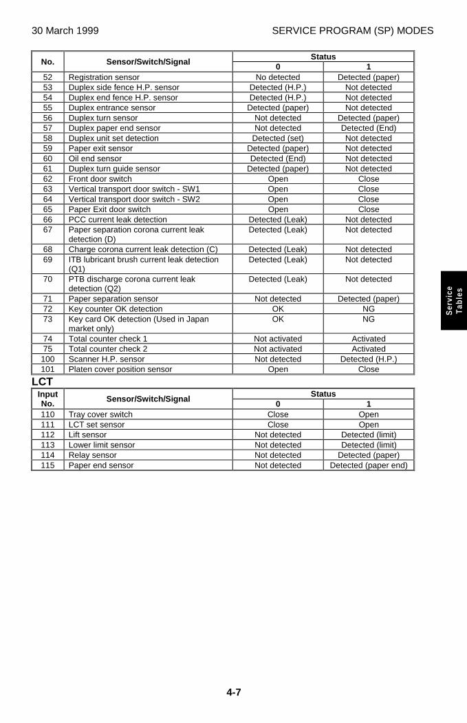
30 March 1999 SERVICE PROGRAM (SP) MODES
4-7
Ser
vice
Tab
les
StatusNo. Sensor/Switch/Signal
0 152 Registration sensor No detected Detected (paper)53 Duplex side fence H.P. sensor Detected (H.P.) Not detected54 Duplex end fence H.P. sensor Detected (H.P.) Not detected55 Duplex entrance sensor Detected (paper) Not detected56 Duplex turn sensor Not detected Detected (paper)57 Duplex paper end sensor Not detected Detected (End)58 Duplex unit set detection Detected (set) Not detected59 Paper exit sensor Detected (paper) Not detected60 Oil end sensor Detected (End) Not detected61 Duplex turn guide sensor Detected (paper) Not detected62 Front door switch Open Close63 Vertical transport door switch - SW1 Open Close64 Vertical transport door switch - SW2 Open Close65 Paper Exit door switch Open Close66 PCC current leak detection Detected (Leak) Not detected67 Paper separation corona current leak
detection (D)Detected (Leak) Not detected
68 Charge corona current leak detection (C) Detected (Leak) Not detected69 ITB lubricant brush current leak detection
(Q1)Detected (Leak) Not detected
70 PTB discharge corona current leakdetection (Q2)
Detected (Leak) Not detected
71 Paper separation sensor Not detected Detected (paper)72 Key counter OK detection OK NG73 Key card OK detection (Used in Japan
market only)OK NG
74 Total counter check 1 Not activated Activated75 Total counter check 2 Not activated Activated
100 Scanner H.P. sensor Not detected Detected (H.P.)101 Platen cover position sensor Open Close
LCTStatusInput
No. Sensor/Switch/Signal0 1
110 Tray cover switch Close Open111 LCT set sensor Close Open112 Lift sensor Not detected Detected (limit)113 Lower limit sensor Not detected Detected (limit)114 Relay sensor Not detected Detected (paper)115 Paper end sensor Not detected Detected (paper end)
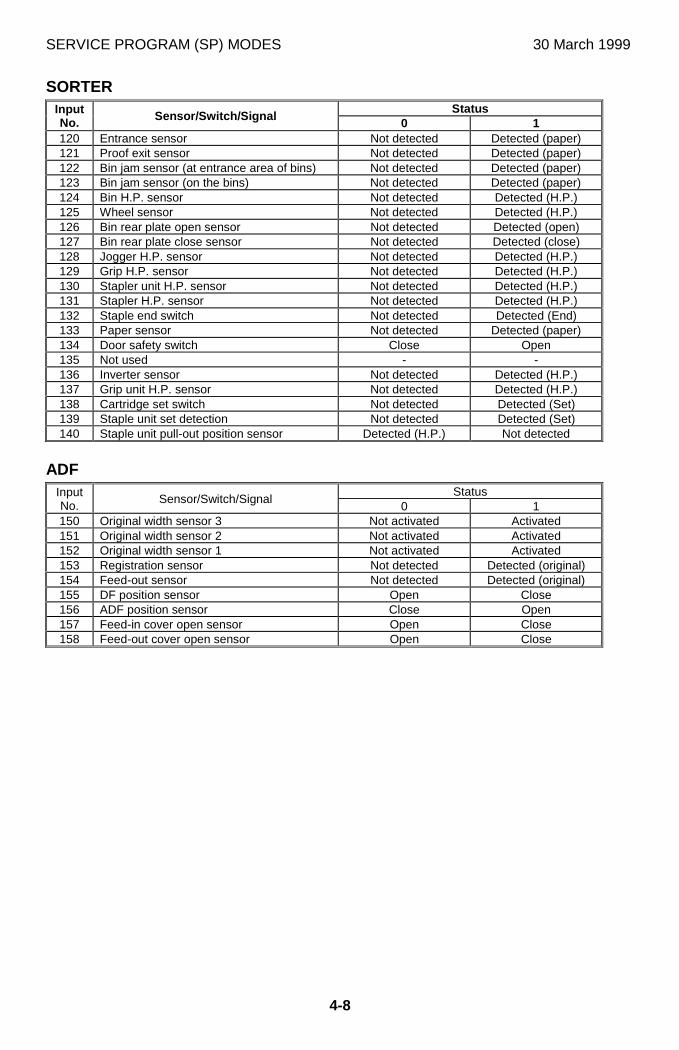
SERVICE PROGRAM (SP) MODES 30 March 1999
4-8
SORTERStatusInput
No. Sensor/Switch/Signal0 1
120 Entrance sensor Not detected Detected (paper)121 Proof exit sensor Not detected Detected (paper)122 Bin jam sensor (at entrance area of bins) Not detected Detected (paper)123 Bin jam sensor (on the bins) Not detected Detected (paper)124 Bin H.P. sensor Not detected Detected (H.P.)125 Wheel sensor Not detected Detected (H.P.)126 Bin rear plate open sensor Not detected Detected (open)127 Bin rear plate close sensor Not detected Detected (close)128 Jogger H.P. sensor Not detected Detected (H.P.)129 Grip H.P. sensor Not detected Detected (H.P.)130 Stapler unit H.P. sensor Not detected Detected (H.P.)131 Stapler H.P. sensor Not detected Detected (H.P.)132 Staple end switch Not detected Detected (End)133 Paper sensor Not detected Detected (paper)134 Door safety switch Close Open135 Not used - -136 Inverter sensor Not detected Detected (H.P.)137 Grip unit H.P. sensor Not detected Detected (H.P.)138 Cartridge set switch Not detected Detected (Set)139 Staple unit set detection Not detected Detected (Set)140 Staple unit pull-out position sensor Detected (H.P.) Not detected
ADFStatusInput
No. Sensor/Switch/Signal0 1
150 Original width sensor 3 Not activated Activated151 Original width sensor 2 Not activated Activated152 Original width sensor 1 Not activated Activated153 Registration sensor Not detected Detected (original)154 Feed-out sensor Not detected Detected (original)155 DF position sensor Open Close156 ADF position sensor Close Open157 Feed-in cover open sensor Open Close158 Feed-out cover open sensor Open Close
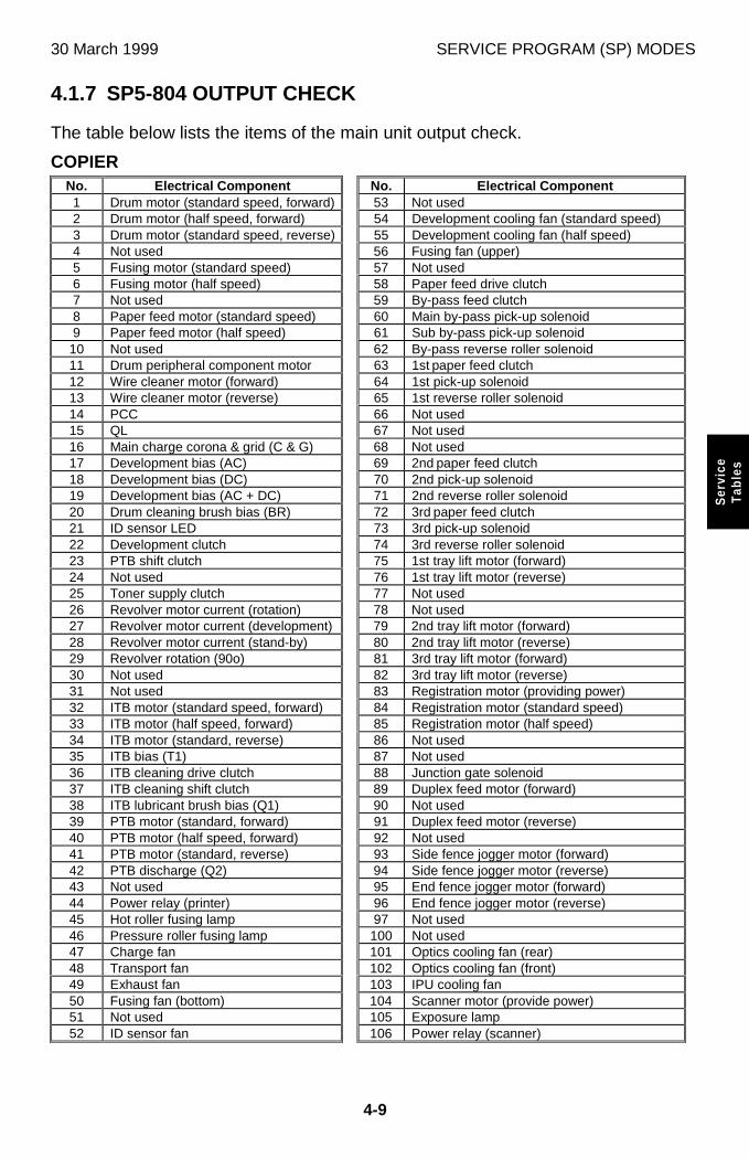
30 March 1999 SERVICE PROGRAM (SP) MODES
4-9
Ser
vice
Tab
les
4.1.7 SP5-804 OUTPUT CHECK
The table below lists the items of the main unit output check.
COPIERNo. Electrical Component No. Electrical Component1 Drum motor (standard speed, forward) 53 Not used2 Drum motor (half speed, forward) 54 Development cooling fan (standard speed)3 Drum motor (standard speed, reverse) 55 Development cooling fan (half speed)4 Not used 56 Fusing fan (upper)5 Fusing motor (standard speed) 57 Not used6 Fusing motor (half speed) 58 Paper feed drive clutch7 Not used 59 By-pass feed clutch8 Paper feed motor (standard speed) 60 Main by-pass pick-up solenoid9 Paper feed motor (half speed) 61 Sub by-pass pick-up solenoid
10 Not used 62 By-pass reverse roller solenoid11 Drum peripheral component motor 63 1st paper feed clutch12 Wire cleaner motor (forward) 64 1st pick-up solenoid13 Wire cleaner motor (reverse) 65 1st reverse roller solenoid14 PCC 66 Not used15 QL 67 Not used16 Main charge corona & grid (C & G) 68 Not used17 Development bias (AC) 69 2nd paper feed clutch18 Development bias (DC) 70 2nd pick-up solenoid19 Development bias (AC + DC) 71 2nd reverse roller solenoid20 Drum cleaning brush bias (BR) 72 3rd paper feed clutch21 ID sensor LED 73 3rd pick-up solenoid22 Development clutch 74 3rd reverse roller solenoid23 PTB shift clutch 75 1st tray lift motor (forward)24 Not used 76 1st tray lift motor (reverse)25 Toner supply clutch 77 Not used26 Revolver motor current (rotation) 78 Not used27 Revolver motor current (development) 79 2nd tray lift motor (forward)28 Revolver motor current (stand-by) 80 2nd tray lift motor (reverse)29 Revolver rotation (90o) 81 3rd tray lift motor (forward)30 Not used 82 3rd tray lift motor (reverse)31 Not used 83 Registration motor (providing power)32 ITB motor (standard speed, forward) 84 Registration motor (standard speed)33 ITB motor (half speed, forward) 85 Registration motor (half speed)34 ITB motor (standard, reverse) 86 Not used35 ITB bias (T1) 87 Not used36 ITB cleaning drive clutch 88 Junction gate solenoid37 ITB cleaning shift clutch 89 Duplex feed motor (forward)38 ITB lubricant brush bias (Q1) 90 Not used39 PTB motor (standard, forward) 91 Duplex feed motor (reverse)40 PTB motor (half speed, forward) 92 Not used41 PTB motor (standard, reverse) 93 Side fence jogger motor (forward)42 PTB discharge (Q2) 94 Side fence jogger motor (reverse)43 Not used 95 End fence jogger motor (forward)44 Power relay (printer) 96 End fence jogger motor (reverse)45 Hot roller fusing lamp 97 Not used46 Pressure roller fusing lamp 100 Not used47 Charge fan 101 Optics cooling fan (rear)48 Transport fan 102 Optics cooling fan (front)49 Exhaust fan 103 IPU cooling fan50 Fusing fan (bottom) 104 Scanner motor (provide power)51 Not used 105 Exposure lamp52 ID sensor fan 106 Power relay (scanner)

SERVICE PROGRAM (SP) MODES 30 March 1999
4-10
To activate the revolver motor 45 or 90 degree, No. 26 “Revolver motor current(rotation)” needs to be ON.
OPTIONS (FPU, SORTER, ADF)
No. Electrical Component No. Electrical Component107 FPU: Lamp 130 Sorter: Reverse solenoid120 Sorter: Transport motor (Proof mode) 131 Sorter: Jogger Motor121 Sorter: Transport motor (Sort mode) 133 Same as 131122 Sorter: Exit motor 150 ADF: Feed-in motor (forward)123 Sorter: Turn gate solenoid 151 ADF: Feed-in motor (reverse)124 Sorter: Bin Motor 152 ADF: Belt drive motor (forward)125 Sorter: Bin rear plate motor 153 ADF: Belt drive motor (reverse)126 Sorter: Grip motor 154 ADF: Feed-out motor127 Sorter: Grip shift motor 155 ADF: Inverter solenoid128 Sorter: Staple unit motor 156 ADF: Indicators ON129 Sorter: Stapler motor
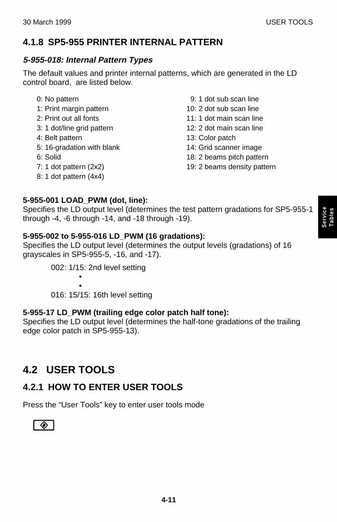
30 March 1999 USER TOOLS
4-11
Ser
vice
Tab
les
4.1.8 SP5-955 PRINTER INTERNAL PATTERN
5-955-018: Internal Pattern Types
The default values and printer internal patterns, which are generated in the LDcontrol board, are listed below.
0: No pattern1: Print margin pattern2: Print out all fonts3: 1 dot/line grid pattern4: Belt pattern5: 16-gradation with blank6: Solid7: 1 dot pattern (2x2)8: 1 dot pattern (4x4)
9: 1 dot sub scan line10: 2 dot sub scan line11: 1 dot main scan line12: 2 dot main scan line13: Color patch14: Grid scanner image18: 2 beams pitch pattern19: 2 beams density pattern
5-955-001 LOAD_PWM (dot, line):Specifies the LD output level (determines the test pattern gradations for SP5-955-1through -4, -6 through -14, and -18 through -19).
5-955-002 to 5-955-016 LD_PWM (16 gradations):Specifies the LD output level (determines the output levels (gradations) of 16grayscales in SP5-955-5, -16, and -17).
002: 1/15: 2nd level setting••
016: 15/15: 16th level setting
5-955-17 LD_PWM (trailing edge color patch half tone):Specifies the LD output level (determines the half-tone gradations of the trailingedge color patch in SP5-955-13).
4.2 USER TOOLS
4.2.1 HOW TO ENTER USER TOOLS
Press the “User Tools” key to enter user tools mode
J
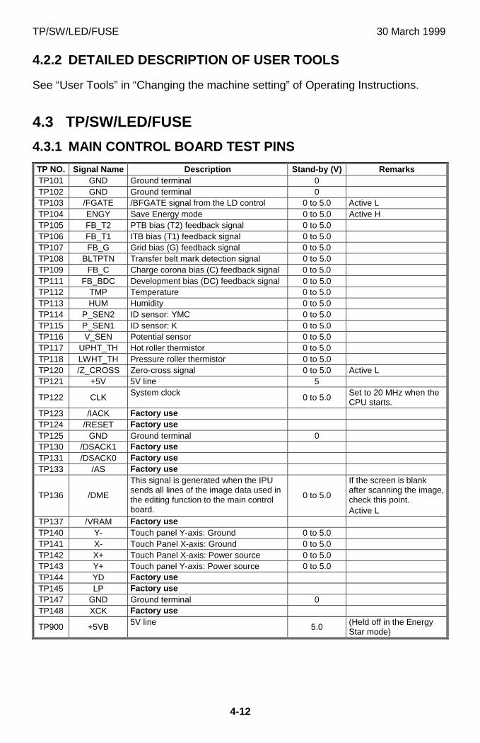
TP/SW/LED/FUSE 30 March 1999
4-12
4.2.2 DETAILED DESCRIPTION OF USER TOOLS
See “User Tools” in “Changing the machine setting” of Operating Instructions.
4.3 TP/SW/LED/FUSE
4.3.1 MAIN CONTROL BOARD TEST PINS
TP NO. Signal Name Description Stand-by (V) RemarksTP101 GND Ground terminal 0TP102 GND Ground terminal 0TP103 /FGATE /BFGATE signal from the LD control 0 to 5.0 Active LTP104 ENGY Save Energy mode 0 to 5.0 Active HTP105 FB_T2 PTB bias (T2) feedback signal 0 to 5.0TP106 FB_T1 ITB bias (T1) feedback signal 0 to 5.0TP107 FB_G Grid bias (G) feedback signal 0 to 5.0TP108 BLTPTN Transfer belt mark detection signal 0 to 5.0TP109 FB_C Charge corona bias (C) feedback signal 0 to 5.0TP111 FB_BDC Development bias (DC) feedback signal 0 to 5.0TP112 TMP Temperature 0 to 5.0TP113 HUM Humidity 0 to 5.0TP114 P_SEN2 ID sensor: YMC 0 to 5.0TP115 P_SEN1 ID sensor: K 0 to 5.0TP116 V_SEN Potential sensor 0 to 5.0TP117 UPHT_TH Hot roller thermistor 0 to 5.0TP118 LWHT_TH Pressure roller thermistor 0 to 5.0TP120 /Z_CROSS Zero-cross signal 0 to 5.0 Active LTP121 +5V 5V line 5
TP122 CLK System clock 0 to 5.0 Set to 20 MHz when theCPU starts.
TP123 /IACK Factory useTP124 /RESET Factory useTP125 GND Ground terminal 0TP130 /DSACK1 Factory useTP131 /DSACK0 Factory useTP133 /AS Factory use
TP136 /DME
This signal is generated when the IPUsends all lines of the image data used inthe editing function to the main controlboard.
0 to 5.0
If the screen is blankafter scanning the image,check this point.Active L
TP137 /VRAM Factory useTP140 Y- Touch panel Y-axis: Ground 0 to 5.0TP141 X- Touch Panel X-axis: Ground 0 to 5.0TP142 X+ Touch Panel X-axis: Power source 0 to 5.0TP143 Y+ Touch panel Y-axis: Power source 0 to 5.0TP144 YD Factory useTP145 LP Factory useTP147 GND Ground terminal 0TP148 XCK Factory use
TP900 +5VB 5V line 5.0 (Held off in the EnergyStar mode)
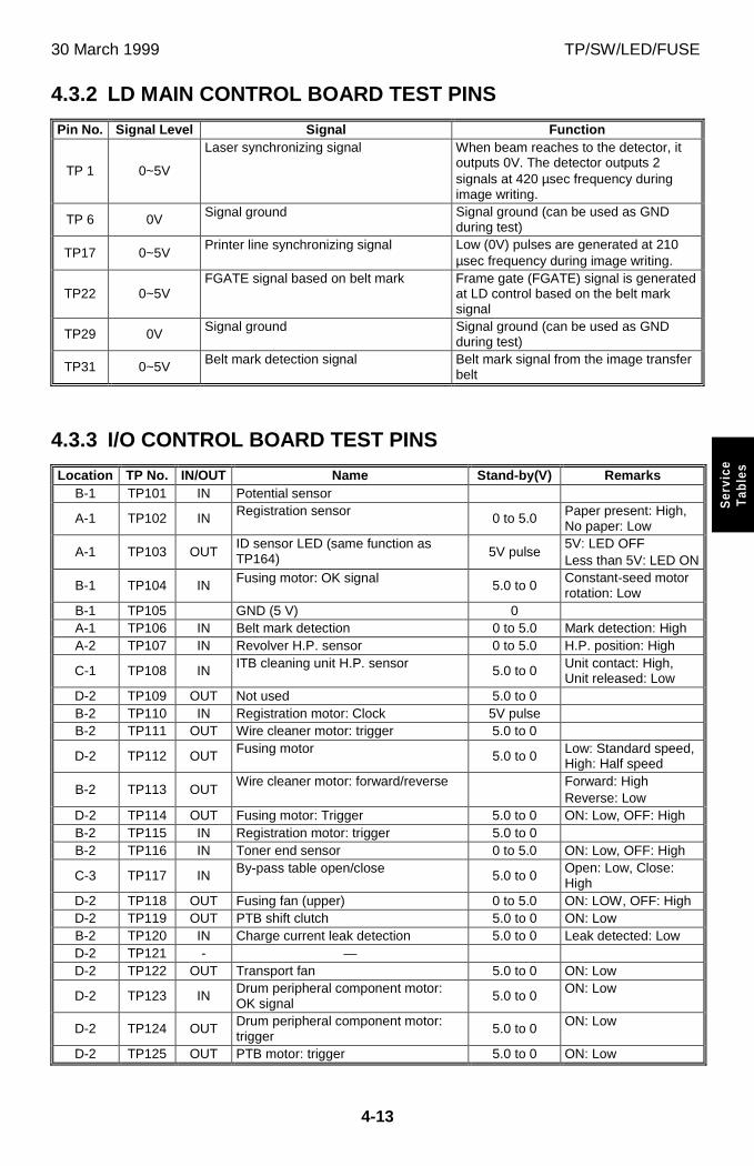
30 March 1999 TP/SW/LED/FUSE
4-13
Ser
vice
Tab
les
4.3.2 LD MAIN CONTROL BOARD TEST PINS
Pin No. Signal Level Signal Function
TP 1 0~5V
Laser synchronizing signal When beam reaches to the detector, itoutputs 0V. The detector outputs 2signals at 420 µsec frequency duringimage writing.
TP 6 0V Signal ground Signal ground (can be used as GNDduring test)
TP17 0~5VPrinter line synchronizing signal Low (0V) pulses are generated at 210
µsec frequency during image writing.
TP22 0~5VFGATE signal based on belt mark Frame gate (FGATE) signal is generated
at LD control based on the belt marksignal
TP29 0V Signal ground Signal ground (can be used as GNDduring test)
TP31 0~5V Belt mark detection signal Belt mark signal from the image transferbelt
4.3.3 I/O CONTROL BOARD TEST PINS
Location TP No. IN/OUT Name Stand-by(V) RemarksB-1 TP101 IN Potential sensor
A-1 TP102 IN Registration sensor 0 to 5.0 Paper present: High,No paper: Low
A-1 TP103 OUTID sensor LED (same function asTP164) 5V pulse
5V: LED OFFLess than 5V: LED ON
B-1 TP104 IN Fusing motor: OK signal 5.0 to 0Constant-seed motorrotation: Low
B-1 TP105 GND (5 V) 0A-1 TP106 IN Belt mark detection 0 to 5.0 Mark detection: HighA-2 TP107 IN Revolver H.P. sensor 0 to 5.0 H.P. position: High
C-1 TP108 IN ITB cleaning unit H.P. sensor 5.0 to 0 Unit contact: High,Unit released: Low
D-2 TP109 OUT Not used 5.0 to 0B-2 TP110 IN Registration motor: Clock 5V pulseB-2 TP111 OUT Wire cleaner motor: trigger 5.0 to 0
D-2 TP112 OUT Fusing motor 5.0 to 0 Low: Standard speed,High: Half speed
B-2 TP113 OUTWire cleaner motor: forward/reverse Forward: High
Reverse: LowD-2 TP114 OUT Fusing motor: Trigger 5.0 to 0 ON: Low, OFF: HighB-2 TP115 IN Registration motor: trigger 5.0 to 0B-2 TP116 IN Toner end sensor 0 to 5.0 ON: Low, OFF: High
C-3 TP117 IN By-pass table open/close 5.0 to 0Open: Low, Close:High
D-2 TP118 OUT Fusing fan (upper) 0 to 5.0 ON: LOW, OFF: HighD-2 TP119 OUT PTB shift clutch 5.0 to 0 ON: LowB-2 TP120 IN Charge current leak detection 5.0 to 0 Leak detected: LowD-2 TP121 - —D-2 TP122 OUT Transport fan 5.0 to 0 ON: Low
D-2 TP123 IN Drum peripheral component motor:OK signal
5.0 to 0 ON: Low
D-2 TP124 OUT Drum peripheral component motor:trigger
5.0 to 0 ON: Low
D-2 TP125 OUT PTB motor: trigger 5.0 to 0 ON: Low
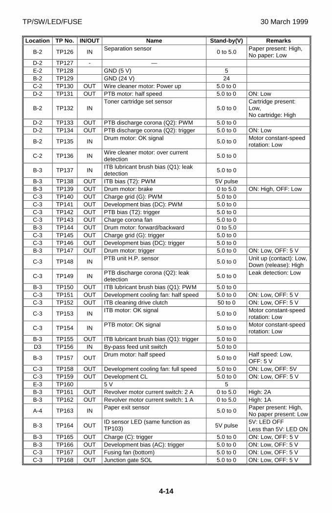
TP/SW/LED/FUSE 30 March 1999
4-14
Location TP No. IN/OUT Name Stand-by(V) Remarks
B-2 TP126 IN Separation sensor 0 to 5.0 Paper present: High,No paper: Low
D-2 TP127 - —E-2 TP128 GND (5 V) 5B-2 TP129 GND (24 V) 24C-2 TP130 OUT Wire cleaner motor: Power up 5.0 to 0D-2 TP131 OUT PTB motor: half speed 5.0 to 0 ON: Low
B-2 TP132 INToner cartridge set sensor
5.0 to 0Cartridge present:Low,No cartridge: High
D-2 TP133 OUT PTB discharge corona (Q2): PWM 5.0 to 0D-2 TP134 OUT PTB discharge corona (Q2): trigger 5.0 to 0 ON: Low
B-2 TP135 IN Drum motor: OK signal 5.0 to 0Motor constant-speedrotation: Low
C-2 TP136 INWire cleaner motor: over currentdetection 5.0 to 0
B-3 TP137 INITB lubricant brush bias (Q1): leakdetection 5.0 to 0
B-3 TP138 OUT ITB bias (T2): PWM 5V pulseB-3 TP139 OUT Drum motor: brake 0 to 5.0 ON: High, OFF: LowC-3 TP140 OUT Charge grid (G): PWM 5.0 to 0C-3 TP141 OUT Development bias (DC): PWM 5.0 to 0C-3 TP142 OUT PTB bias (T2): trigger 5.0 to 0C-3 TP143 OUT Charge corona fan 5.0 to 0B-3 TP144 OUT Drum motor: forward/backward 0 to 5.0C-3 TP145 OUT Charge grid (G): trigger 5.0 to 0C-3 TP146 OUT Development bias (DC): trigger 5.0 to 0B-3 TP147 OUT Drum motor: trigger 5.0 to 0 ON: Low, OFF: 5 V
C-3 TP148 IN PTB unit H.P. sensor 5.0 to 0 Unit up (contact): Low,Down (release): High
C-3 TP149 IN PTB discharge corona (Q2): leakdetection 5.0 to 0 Leak detection: Low
B-3 TP150 OUT ITB lubricant brush bias (Q1): PWM 5.0 to 0C-3 TP151 OUT Development cooling fan: half speed 5.0 to 0 ON: Low, OFF: 5 VC-3 TP152 OUT ITB cleaning drive clutch 50 to 0 ON: Low, OFF: 5 V
C-3 TP153 IN ITB motor: OK signal 5.0 to 0 Motor constant-speedrotation: Low
C-3 TP154 IN PTB motor: OK signal 5.0 to 0 Motor constant-speedrotation: Low
B-3 TP155 OUT ITB lubricant brush bias (Q1): trigger 5.0 to 0D3 TP156 IN By-pass feed unit switch 5.0 to 0
B-3 TP157 OUT Drum motor: half speed 5.0 to 0Half speed: Low,OFF: 5 V
C-3 TP158 OUT Development cooling fan: full speed 5.0 to 0 ON: Low, OFF: 5VC-3 TP159 OUT Development CL 5.0 to 0 ON: Low, OFF: 5 VE-3 TP160 5 V 5B-3 TP161 OUT Revolver motor current switch: 2 A 0 to 5.0 High: 2AB-3 TP162 OUT Revolver motor current switch: 1 A 0 to 5.0 High: 1A
A-4 TP163 IN Paper exit sensor 5.0 to 0 Paper present: High,No paper present: Low
B-3 TP164 OUTID sensor LED (same function asTP103) 5V pulse
5V: LED OFFLess than 5V: LED ON
B-3 TP165 OUT Charge (C): trigger 5.0 to 0 ON: Low, OFF: 5 VB-3 TP166 OUT Development bias (AC): trigger 5.0 to 0 ON: Low, OFF: 5 VC-3 TP167 OUT Fusing fan (bottom) 5.0 to 0 ON: Low, OFF: 5 VC-3 TP168 OUT Junction gate SOL 5.0 to 0 ON: Low, OFF: 5 V
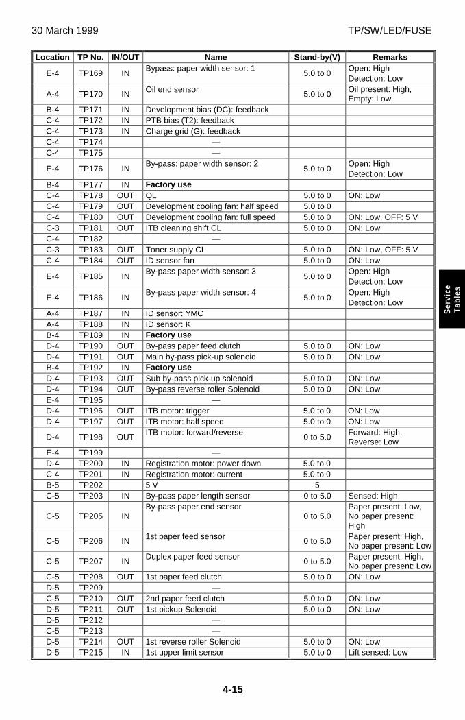
30 March 1999 TP/SW/LED/FUSE
4-15
Ser
vice
Tab
les
Location TP No. IN/OUT Name Stand-by(V) Remarks
E-4 TP169 INBypass: paper width sensor: 1
5.0 to 0Open: HighDetection: Low
A-4 TP170 IN Oil end sensor 5.0 to 0Oil present: High,Empty: Low
B-4 TP171 IN Development bias (DC): feedbackC-4 TP172 IN PTB bias (T2): feedbackC-4 TP173 IN Charge grid (G): feedbackC-4 TP174 —C-4 TP175 —
E-4 TP176 INBy-pass: paper width sensor: 2
5.0 to 0Open: HighDetection: Low
B-4 TP177 IN Factory useC-4 TP178 OUT QL 5.0 to 0 ON: LowC-4 TP179 OUT Development cooling fan: half speed 5.0 to 0C-4 TP180 OUT Development cooling fan: full speed 5.0 to 0 ON: Low, OFF: 5 VC-3 TP181 OUT ITB cleaning shift CL 5.0 to 0 ON: LowC-4 TP182 —C-3 TP183 OUT Toner supply CL 5.0 to 0 ON: Low, OFF: 5 VC-4 TP184 OUT ID sensor fan 5.0 to 0 ON: Low
E-4 TP185 INBy-pass paper width sensor: 3
5.0 to 0Open: HighDetection: Low
E-4 TP186 INBy-pass paper width sensor: 4
5.0 to 0Open: HighDetection: Low
A-4 TP187 IN ID sensor: YMCA-4 TP188 IN ID sensor: KB-4 TP189 IN Factory useD-4 TP190 OUT By-pass paper feed clutch 5.0 to 0 ON: LowD-4 TP191 OUT Main by-pass pick-up solenoid 5.0 to 0 ON: LowB-4 TP192 IN Factory useD-4 TP193 OUT Sub by-pass pick-up solenoid 5.0 to 0 ON: LowD-4 TP194 OUT By-pass reverse roller Solenoid 5.0 to 0 ON: LowE-4 TP195 —D-4 TP196 OUT ITB motor: trigger 5.0 to 0 ON: LowD-4 TP197 OUT ITB motor: half speed 5.0 to 0 ON: Low
D-4 TP198 OUT ITB motor: forward/reverse 0 to 5.0 Forward: High,Reverse: Low
E-4 TP199 —D-4 TP200 IN Registration motor: power down 5.0 to 0C-4 TP201 IN Registration motor: current 5.0 to 0B-5 TP202 5 V 5C-5 TP203 IN By-pass paper length sensor 0 to 5.0 Sensed: High
C-5 TP205 INBy-pass paper end sensor
0 to 5.0Paper present: Low,No paper present:High
C-5 TP206 IN 1st paper feed sensor 0 to 5.0 Paper present: High,No paper present: Low
C-5 TP207 IN Duplex paper feed sensor 0 to 5.0 Paper present: High,No paper present: Low
C-5 TP208 OUT 1st paper feed clutch 5.0 to 0 ON: LowD-5 TP209 —C-5 TP210 OUT 2nd paper feed clutch 5.0 to 0 ON: LowD-5 TP211 OUT 1st pickup Solenoid 5.0 to 0 ON: LowD-5 TP212 —C-5 TP213 —D-5 TP214 OUT 1st reverse roller Solenoid 5.0 to 0 ON: LowD-5 TP215 IN 1st upper limit sensor 5.0 to 0 Lift sensed: Low
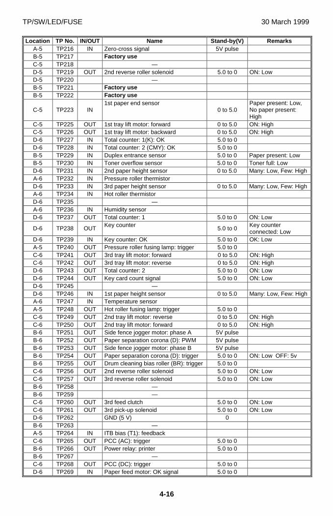
TP/SW/LED/FUSE 30 March 1999
4-16
Location TP No. IN/OUT Name Stand-by(V) RemarksA-5 TP216 IN Zero-cross signal 5V pulseB-5 TP217 Factory useC-5 TP218 —D-5 TP219 OUT 2nd reverse roller solenoid 5.0 to 0 ON: LowD-5 TP220 —B-5 TP221 Factory useB-5 TP222 Factory use
C-5 TP223 IN1st paper end sensor
0 to 5.0Paper present: Low,No paper present:High
C-5 TP225 OUT 1st tray lift motor: forward 0 to 5.0 ON: HighC-5 TP226 OUT 1st tray lift motor: backward 0 to 5.0 ON: HighD-6 TP227 IN Total counter: 1(K): OK 5.0 to 0D-6 TP228 IN Total counter: 2 (CMY): OK 5.0 to 0B-5 TP229 IN Duplex entrance sensor 5.0 to 0 Paper present: LowB-5 TP230 IN Toner overflow sensor 5.0 to 0 Toner full: LowD-6 TP231 IN 2nd paper height sensor 0 to 5.0 Many: Low, Few: HighA-6 TP232 IN Pressure roller thermistorD-6 TP233 IN 3rd paper height sensor 0 to 5.0 Many: Low, Few: HighA-6 TP234 IN Hot roller thermistorD-6 TP235 —A-6 TP236 IN Humidity sensorD-6 TP237 OUT Total counter: 1 5.0 to 0 ON: Low
D-6 TP238 OUT Key counter 5.0 to 0 Key counterconnected: Low
D-6 TP239 IN Key counter: OK 5.0 to 0 OK: LowA-5 TP240 OUT Pressure roller fusing lamp: trigger 5.0 to 0C-6 TP241 OUT 3rd tray lift motor: forward 0 to 5.0 ON: HighC-6 TP242 OUT 3rd tray lift motor: reverse 0 to 5.0 ON: HighD-6 TP243 OUT Total counter: 2 5.0 to 0 ON: LowD-6 TP244 OUT Key card count signal 5.0 to 0 ON: LowD-6 TP245 —D-6 TP246 IN 1st paper height sensor 0 to 5.0 Many: Low, Few: HighA-6 TP247 IN Temperature sensorA-5 TP248 OUT Hot roller fusing lamp: trigger 5.0 to 0C-6 TP249 OUT 2nd tray lift motor: reverse 0 to 5.0 ON: HighC-6 TP250 OUT 2nd tray lift motor: forward 0 to 5.0 ON: HighB-6 TP251 OUT Side fence jogger motor: phase A 5V pulseB-6 TP252 OUT Paper separation corona (D): PWM 5V pulseB-6 TP253 OUT Side fence jogger motor: phase B 5V pulseB-6 TP254 OUT Paper separation corona (D): trigger 5.0 to 0 ON: Low OFF: 5vB-6 TP255 OUT Drum cleaning bias roller (BR): trigger 5.0 to 0C-6 TP256 OUT 2nd reverse roller solenoid 5.0 to 0 ON: LowC-6 TP257 OUT 3rd reverse roller solenoid 5.0 to 0 ON: LowB-6 TP258 —B-6 TP259 —C-6 TP260 OUT 3rd feed clutch 5.0 to 0 ON: LowC-6 TP261 OUT 3rd pick-up solenoid 5.0 to 0 ON: LowD-6 TP262 GND (5 V) 0B-6 TP263 —A-5 TP264 IN ITB bias (T1): feedbackC-6 TP265 OUT PCC (AC): trigger 5.0 to 0B-6 TP266 OUT Power relay: printer 5.0 to 0B-6 TP267 —C-6 TP268 OUT PCC (DC): trigger 5.0 to 0D-6 TP269 IN Paper feed motor: OK signal 5.0 to 0
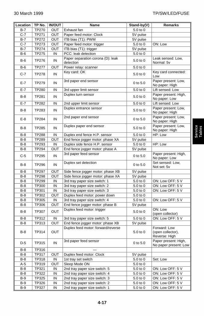
30 March 1999 TP/SW/LED/FUSE
4-17
Ser
vice
Tab
les
Location TP No. IN/OUT Name Stand-by(V) RemarksB-7 TP270 OUT Exhaust fan 5.0 to 0C-7 TP271 OUT Paper feed motor: Clock 5V pulseB-7 TP272 OUT ITB bias (T1): PWM 5V pulseC-7 TP273 OUT Paper feed motor: trigger 5.0 to 0 ON: LowB-7 TP274 OUT ITB bias (T1): trigger 5V pulseB-6 TP275 IN PCC: leak detection 5.0 to 0
B-6 TP276 INPaper separation corona (D): leakdetection 5.0 to 0
Leak sensed: Low,Normal: 5v
B-6 TP277 OUT Power relay: scanner 5.0 to 0
C-7 TP278 IN Key card: OK 5.0 to 0Key card connected:Low
E-7 TP279 IN 3rd paper end sensor 0 to 5.0 Paper present: Low,No paper: High
E-7 TP280 IN 3rd upper limit sensor 5.0 to 0 Lift sensed: Low
B-8 TP281 IN Duplex turn sensor 5.0 to 0 Paper present: High,No paper: Low
E-7 TP282 IN 2nd upper limit sensor 5.0 to 0 Lift sensed: Low
B-8 TP283 IN Duplex entrance sensor 5.0 to 0 Paper present: Low,No paper: High
E-8 TP284 IN 2nd paper end sensor 0 to 5.0 Paper present: Low,No paper: High
B-8 TP285 IN Duplex paper end sensor 5.0 to 0 Paper present: Low,No paper: High
B-8 TP288 IN Duplex end fence H.P. sensor 5.0 to 0 HP: LowB-8 TP289 OUT End fence jogger motor: phase XA 5V pulseB-8 TP293 IN Duplex side fence H.P. sensor 5.0 to 0 HP: LowB-8 TP294 OUT End fence jogger motor: phase A 5V pulse
C-5 TP295 IN 3rd paper feed sensor 0 to 5.0 Paper present: High,No paper: Low
B-8 TP296 IN Duplex set detection 0 to 5.0 Set sensed: Low,Not set: 5v
B-8 TP297 OUT Side fence jogger motor: phase XB 5V pulseB-8 TP298 OUT Side fence jogger motor: phase XA 5V pulseB-8 TP299 IN 3rd tray paper size switch: 1 5.0 to 0 ON: Low OFF: 5 VB-8 TP300 IN 3rd tray paper size switch: 2 5.0 to 0 ON: Low OFF: 5 VB-8 TP301 IN 3rd tray paper size switch: 3 5.0 to 0 ON: Low OFF: 5 VB-8 TP302 OUT Duplex feed motor: power down 5.0 to 0B-8 TP305 IN 3rd tray paper size switch: 4 5.0 to 0 ON: Low OFF: 5 VB-8 TP306 OUT End fence jogger motor: phase B 5V pulse
B-8 TP307 OUT Duplex feed motor: trigger 5.0 to 0ON: Low(open collector)
B-8 TP312 IN 3rd tray paper size switch: 5 5.0 to 0 ON: Low OFF: 5 VB-8 TP313 OUT End fence jogger motor: phase XB 5V pulse
B-8 TP314 OUTDuplex feed motor: forward/reverse
5.0 to 0Forward: Low(open collector),Reverse: High
D-5 TP315 IN 3rd paper feed sensor 0 to 5.0 Paper present: High,No paper present: Low
B-8 TP316 —B-8 TP317 OUT Duplex feed motor: Clock 5V pulseB-8 TP318 IN 1st tray set switch 5.0 to 0 Set: LowA-5 TP319 OUT Sleep Mode ON 5.0 to 0B-8 TP321 IN 2nd tray paper size switch: 5 5.0 to 0 ON: Low OFF: 5 VB-8 TP322 IN 2nd tray paper size switch: 4 5.0 to 0 ON: Low OFF: 5 VB-9 TP325 IN 2nd tray paper size switch: 3 5.0 to 0 ON: Low OFF: 5 VB-9 TP326 IN 2nd tray paper size switch: 2 5.0 to 0 ON: Low OFF: 5 VB-9 TP327 IN 2nd tray paper size switch: 1 5.0 to 0 ON: Low OFF: 5 V
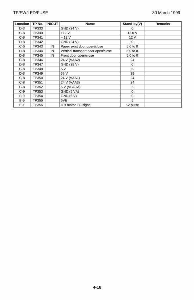
TP/SW/LED/FUSE 30 March 1999
4-18
Location TP No. IN/OUT Name Stand-by(V) RemarksD-3 TP333 GND (24 V) 0C-8 TP340 +12 V 12.0 VC-8 TP341 – 12 V 12 VD-8 TP342 GND (24 V) 0C-6 TP343 IN Paper exist door open/close 5.0 to 0D-8 TP344 IN Vertical transport door open/close 5.0 to 0D-8 TP345 IN Front door open/close 5.0 to 0C-8 TP346 24 V (VAA2) 24D-8 TP347 GND (38 V) 0C-8 TP348 5 V 5D-8 TP349 38 V 38C-8 TP350 24 V (VAA1) 24C-8 TP351 24 V (VAA3) 24C-8 TP352 5 V (VCC1A) 5C-9 TP353 GND (5 VA) 0B-9 TP354 GND (5 V) 0B-9 TP355 5VE 5E-1 TP356 ITB motor FG signal 5V pulse
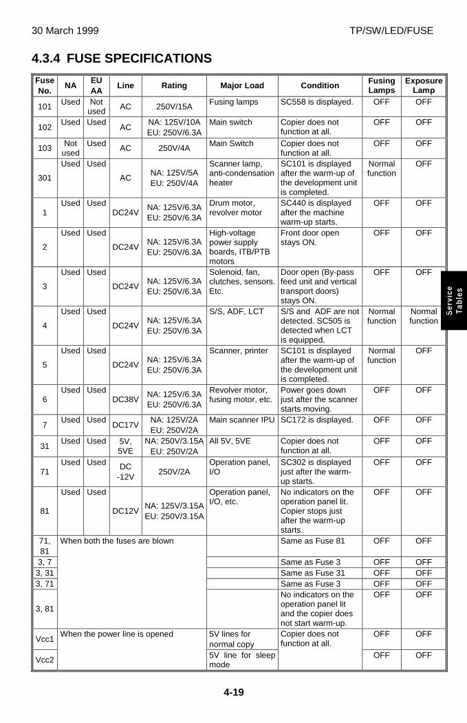
30 March 1999 TP/SW/LED/FUSE
4-19
Ser
vice
Tab
les
4.3.4 FUSE SPECIFICATIONS
FuseNo.
NAEUAA
Line Rating Major Load Condition FusingLamps
ExposureLamp
101 Used Notused AC 250V/15A Fusing lamps SC558 is displayed. OFF OFF
102Used Used
ACNA: 125V/10AEU: 250V/6.3A
Main switch Copier does notfunction at all.
OFF OFF
103 Notused
Used AC 250V/4A Main Switch Copier does notfunction at all.
OFF OFF
301
Used Used
ACNA: 125V/5AEU: 250V/4A
Scanner lamp,anti-condensationheater
SC101 is displayedafter the warm-up ofthe development unitis completed.
Normalfunction
OFF
1Used Used
DC24VNA: 125V/6.3AEU: 250V/6.3A
Drum motor,revolver motor
SC440 is displayedafter the machinewarm-up starts.
OFF OFF
2
Used Used
DC24VNA: 125V/6.3AEU: 250V/6.3A
High-voltagepower supplyboards, ITB/PTBmotors
Front door openstays ON.
OFF OFF
3
Used Used
DC24VNA: 125V/6.3AEU: 250V/6.3A
Solenoid, fan,clutches, sensors.Etc.
Door open (By-passfeed unit and verticaltransport doors)stays ON.
OFF OFF
4
Used Used
DC24VNA: 125V/6.3AEU: 250V/6.3A
S/S, ADF, LCT S/S and ADF are notdetected. SC505 isdetected when LCTis equipped.
Normalfunction
Normalfunction
5
Used Used
DC24VNA: 125V/6.3AEU: 250V/6.3A
Scanner, printer SC101 is displayedafter the warm-up ofthe development unitis completed.
Normalfunction
OFF
6Used Used
DC38VNA: 125V/6.3AEU: 250V/6.3A
Revolver motor,fusing motor, etc.
Power goes downjust after the scannerstarts moving.
OFF OFF
7Used Used
DC17VNA: 125V/2AEU: 250V/2A
Main scanner IPU SC172 is displayed. OFF OFF
31Used Used 5V,
5VENA: 250V/3.15A
EU: 250V/2AAll 5V, 5VE Copier does not
function at all.OFF OFF
71Used Used DC
-12V250V/2A
Operation panel,I/O
SC302 is displayedjust after the warm-up starts.
OFF OFF
81
Used Used
DC12VNA: 125V/3.15AEU: 250V/3.15A
Operation panel,I/O, etc.
No indicators on theoperation panel lit.Copier stops justafter the warm-upstarts.
OFF OFF
71,81
Same as Fuse 81 OFF OFF
3, 7 Same as Fuse 3 OFF OFF3, 31 Same as Fuse 31 OFF OFF3, 71 Same as Fuse 3 OFF OFF
3, 81
When both the fuses are blown
No indicators on theoperation panel litand the copier doesnot start warm-up.
OFF OFF
Vcc15V lines fornormal copy
OFF OFF
Vcc2
When the power line is opened
5V line for sleepmode
Copier does notfunction at all.
OFF OFF
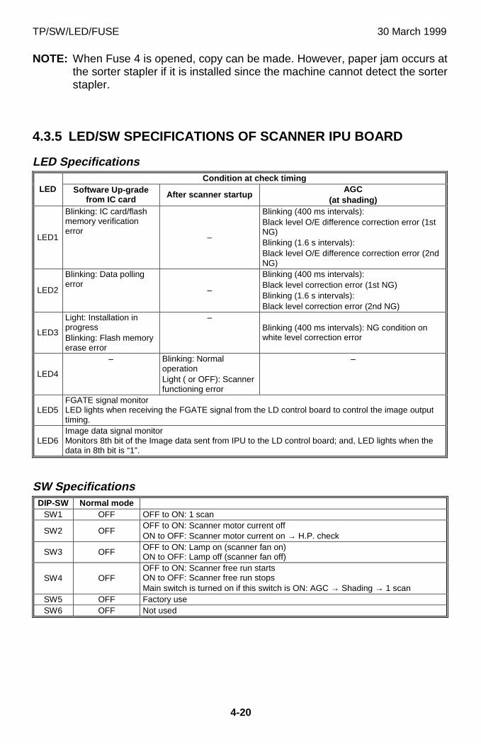
TP/SW/LED/FUSE 30 March 1999
4-20
NOTE: When Fuse 4 is opened, copy can be made. However, paper jam occurs atthe sorter stapler if it is installed since the machine cannot detect the sorterstapler.
4.3.5 LED/SW SPECIFICATIONS OF SCANNER IPU BOARD
LED SpecificationsCondition at check timing
LED Software Up-gradefrom IC card After scanner startup
AGC(at shading)
LED1
Blinking: IC card/flashmemory verificationerror
–
Blinking (400 ms intervals):Black level O/E difference correction error (1stNG)Blinking (1.6 s intervals):Black level O/E difference correction error (2ndNG)
LED2
Blinking: Data pollingerror
–
Blinking (400 ms intervals):Black level correction error (1st NG)Blinking (1.6 s intervals):Black level correction error (2nd NG)
LED3
Light: Installation inprogressBlinking: Flash memoryerase error
–Blinking (400 ms intervals): NG condition onwhite level correction error
LED4
– Blinking: NormaloperationLight ( or OFF): Scannerfunctioning error
–
LED5FGATE signal monitorLED lights when receiving the FGATE signal from the LD control board to control the image outputtiming.
LED6Image data signal monitorMonitors 8th bit of the Image data sent from IPU to the LD control board; and, LED lights when thedata in 8th bit is “1”.
SW SpecificationsDIP-SW Normal mode
SW1 OFF OFF to ON: 1 scan
SW2 OFFOFF to ON: Scanner motor current offON to OFF: Scanner motor current on → H.P. check
SW3 OFF OFF to ON: Lamp on (scanner fan on)ON to OFF: Lamp off (scanner fan off)
SW4 OFFOFF to ON: Scanner free run startsON to OFF: Scanner free run stopsMain switch is turned on if this switch is ON: AGC → Shading → 1 scan
SW5 OFF Factory useSW6 OFF Not used
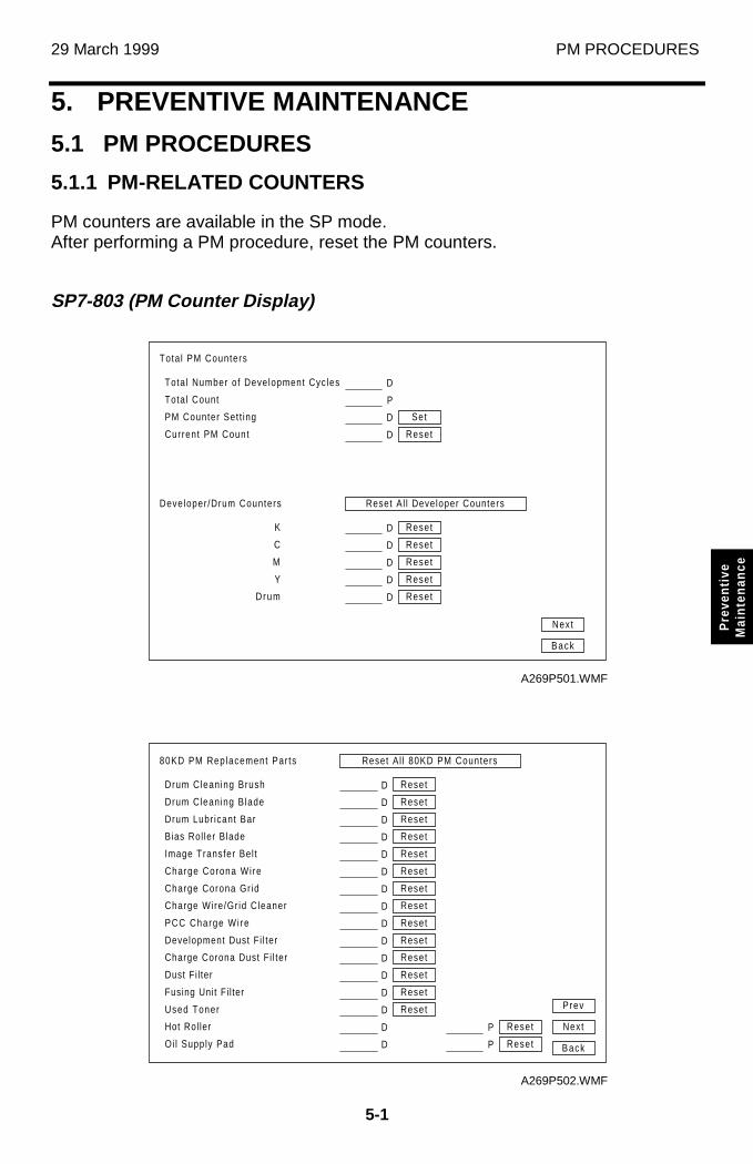
29 March 1999 PM PROCEDURES
5-1
Pre
vent
ive
Mai
nten
ance
5. PREVENTIVE MAINTENANCE
5.1 PM PROCEDURES
5.1.1 PM-RELATED COUNTERS
PM counters are available in the SP mode.After performing a PM procedure, reset the PM counters.
SP7-803 (PM Counter Display)
Reset Al l Developer Counters
Tota l PM Counters
Tota l Number of Development Cycles
Total Count
PM Counter Set t ing
Current PM Count
Developer /Drum Counters
D
D
P
D
Set
Reset
D
D
D
D
D
Reset
Reset
Reset
Reset
Reset
K
C
M
Y
Drum
Next
Back
A269P501.WMF
Reset Al l 80KD PM Counters80KD PM Replacement Par ts
Charge Wire/Gr id Cleaner
PCC Charge Wi re
Development Dust Fi l ter
Charge Corona Dust Fi l ter
Dust Fi l ter
Fusing Unit Fi l ter
Used Toner
Hot Rol ler
Oi l Supply Pad
D Reset
D
D
D
D
Reset
Reset
D
D
D
Reset
Reset
Reset
D Reset
Drum Cleaning Brush D Reset
Drum Cleaning Blade D Reset
Drum Lubr icant Bar D Reset
Bias Rol ler Blade D Reset
Image Transfer Bel t D Reset
Charge Corona Wire D Reset
Charge Corona Gr id D Reset
P
P
Reset
Reset Back
Next
Prev
A269P502.WMF
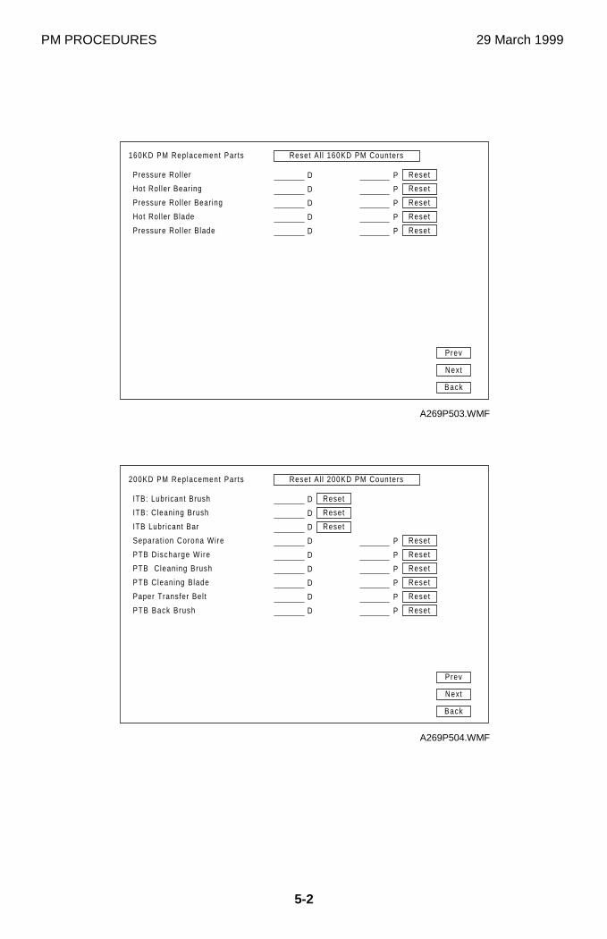
PM PROCEDURES 29 March 1999
5-2
Reset Al l 160KD PM Counters160KD PM Replacement Par ts
Pressure Rol ler D
Hot Rol ler Bearing D
Pressure Rol ler Bear ing D
Hot Rol ler Blade D
Pressure Rol ler Blade D
P Reset
P Reset
P Reset
P Reset
P Reset
Back
Next
Prev
A269P503.WMF
Reset Al l 200KD PM Counters200KD PM Replacement Par ts
Paper Transfer Bel t
PTB Back Brush
D
D
ITB: Lubr icant Brush D Reset
ITB: Cleaning Brush D Reset
ITB Lubr icant Bar D Reset
Separat ion Corona Wire D
PTB Discharge Wire D
PTB Cleaning Brush D
PTB Cleaning Blade D
P Reset
P Reset
P Reset
P Reset
P Reset
P Reset
Back
Next
Prev
A269P504.WMF
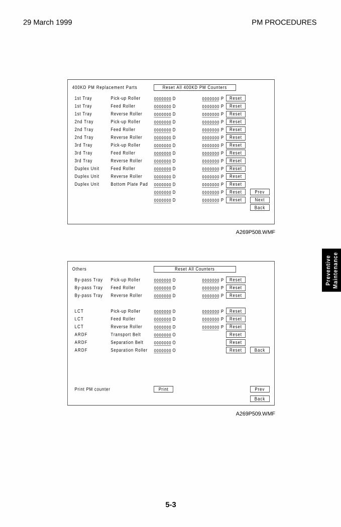
29 March 1999 PM PROCEDURES
5-3
Pre
vent
ive
Mai
nten
ance
Reset Al l CountersOthers
O
O
O
By-pass Tray D
By-pass Tray D
By-pass Tray D
D
D
D
0000000
0000000
0000000
0000000
0000000
0000000
0000000
0000000
0000000
P Reset
P Reset
P Reset
P Reset
P Reset
P Reset
0000000
0000000
0000000
0000000
0000000
0000000
A R D F
A R D F
A R D F
L C T
L C T
L C T
Transport Bel t
Separat ion Bel t
Separat ion Rol ler
Pick-up Rol ler
Feed Rol ler
Reverse Rol ler
Pick-up Rol ler
Feed Rol ler
Reverse Rol ler
Reset
Reset
Reset
Back
Back
PrevPrint PM counter Print
A269P509.WMF
Reset Al l 400KD PM Counters400KD PM Replacement Par ts
D
D
D
D
D
D
D
D
D
D
D
D
D
D
0000000
0000000
0000000
0000000
0000000
0000000
0000000
0000000
0000000
0000000
0000000
0000000
0000000
0000000
P Reset
P
P
P
P
Reset
Reset
P Reset
Reset
Reset
P Reset
P Reset
P Reset
P Reset
P Reset
P Reset
P Reset
P Reset
0000000
0000000
0000000
0000000
0000000
0000000
0000000
0000000
0000000
0000000
0000000
0000000
0000000
0000000
Prev
Next
Back
Duplex Uni t
Duplex Uni t
Duplex Uni t
Feed Rol ler
Reverse Rol ler
Bot tom Plate Pad
3rd Tray
3rd Tray
1st Tray
1st Tray
1st Tray
2nd Tray
2nd Tray
2nd Tray
3rd Tray
Feed Rol ler
Reverse Rol ler
Pick-up Rol ler
Feed Rol ler
Reverse Rol ler
Pick-up Rol ler
Feed Rol ler
Reverse Rol ler
Pick-up Rol ler
A269P508.WMF
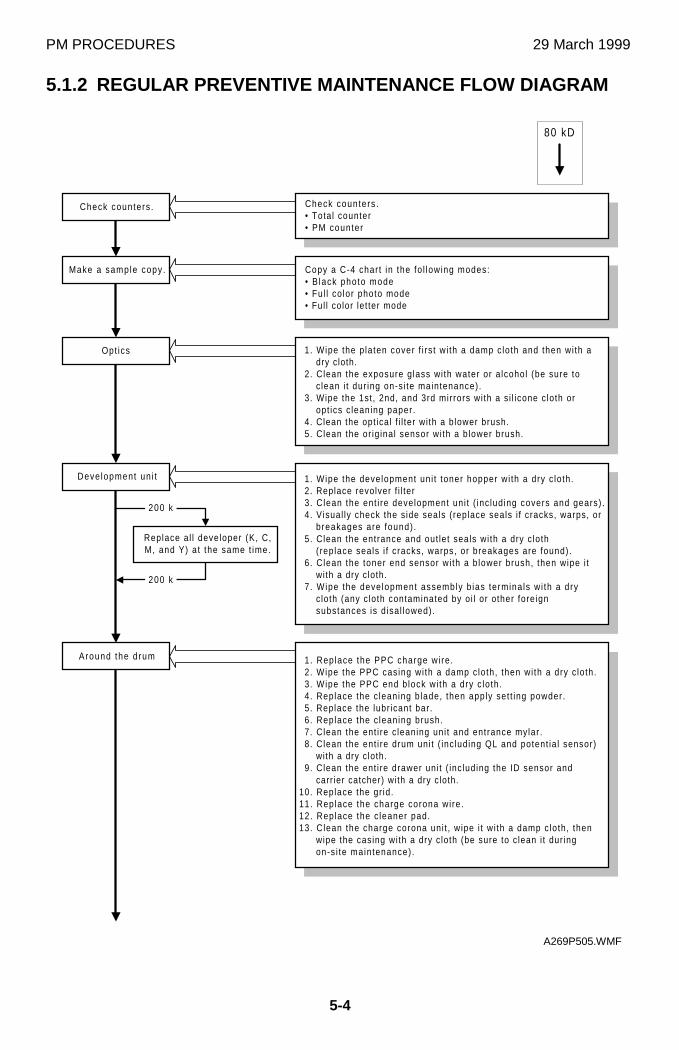
PM PROCEDURES 29 March 1999
5-4
5.1.2 REGULAR PREVENTIVE MAINTENANCE FLOW DIAGRAM
������������
80 kD
200 k
200 k
������������
������������
������������
������������
1. Wipe the p laten cover f i rs t wi th a damp c loth and then wi th adry cloth.
2. Clean the exposure g lass wi th water or a lcohol (be sure toc lean i t dur ing on-s i te maintenance).
3. Wipe the 1st , 2nd, and 3rd mirrors wi th a s i l icone c loth oropt ics c leaning paper.
4. Clean the opt ical f i l ter wi th a blower brush.5. Clean the or ig inal sensor wi th a b lower brush.
1. Replace the PPC charge wi re .2. Wipe the PPC casing wi th a damp c loth, then wi th a dry c lo th.3. Wipe the PPC end b lock wi th a dry c lo th.4. Replace the c leaning b lade, then apply set t ing powder.5. Replace the lubr icant bar.6. Replace the c leaning brush.7. Clean the ent i re c leaning uni t and entrance mylar .8. Clean the ent i re drum uni t ( inc luding QL and potent ia l sensor)
with a dry cloth.9. Clean the ent i re drawer uni t ( inc luding the ID sensor and
carr ier catcher) with a dry cloth.10. Replace the gr id.11. Replace the charge corona wi re.12. Replace the c leaner pad.13. Clean the charge corona uni t , wipe i t wi th a damp c loth, then
wipe the casing wi th a dry c loth (be sure to c lean i t dur ingon-s i te maintenance) .
Check counters .• Total counter• PM counter
Copy a C-4 char t in the fo l lowing modes:• B lack photo mode• Ful l co lor photo mode• Ful l color let ter mode
1. Wipe the development uni t toner hopper wi th a dry c lo th.2. Replace revolver f i l ter3. Clean the ent i re development uni t ( inc luding covers and gears) .4. Visual ly check the s ide seals (replace seals i f cracks, warps, or
breakages are found) .5. Clean the entrance and out let seals wi th a dry c loth
(replace seals i f cracks, warps, or breakages are found).6. Clean the toner end sensor wi th a b lower brush, then wipe i t
wi th a dry cloth.7 . Wipe the development assembly b ias termina ls wi th a dry
cloth (any c loth contaminated by oi l or other foreignsubstances is d isa l lowed).
Check counters .
Opt ics
Deve lopment un i t
Around the d rum
Make a sample copy .
Replace a l l developer (K, C,M, and Y) a t the same t ime.
A269P505.WMF
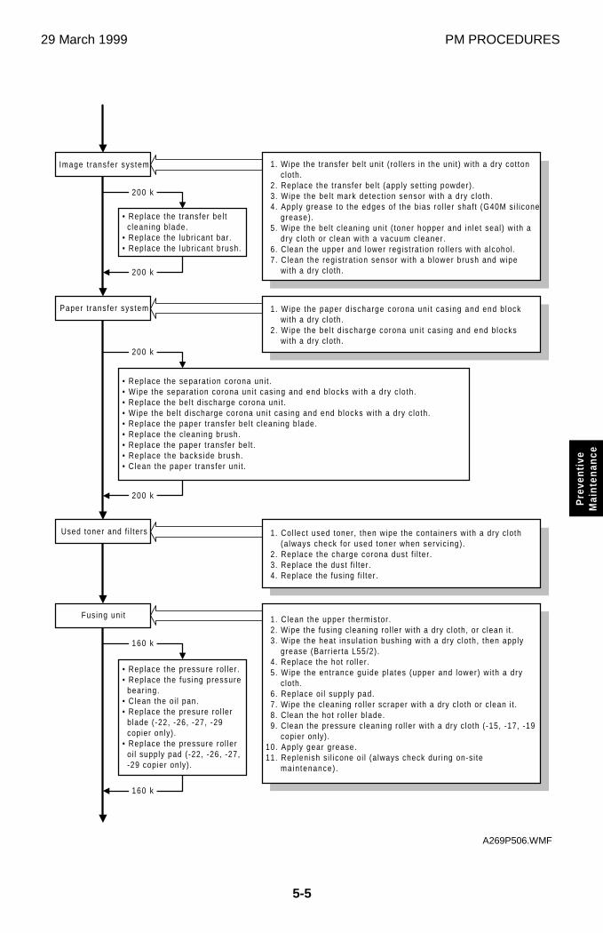
29 March 1999 PM PROCEDURES
5-5
Pre
vent
ive
Mai
nten
ance
������������
200 k
200 k������������
200 k
������������
160 k
160 k
200 k
������������
1. Wipe the paper d ischarge corona uni t cas ing and end b lockwith a dry cloth.
2. Wipe the bel t d ischarge corona uni t cas ing and end b lockswith a dry cloth.
• Replace the t ransfer bel tc leaning b lade.
• Replace the lubr icant bar.• Replace the lubr icant brush.
Image t ransfer sys tem
1. Clean the upper thermistor .2. Wipe the fusing cleaning rol ler wi th a dry c loth, or c lean i t .3 . Wipe the heat insulat ion bushing wi th a dry c loth, then apply
grease (Barr ier ta L55/2) .4. Replace the hot rol ler .5 . Wipe the entrance guide p lates (upper and lower) wi th a dry
cloth.6. Replace o i l supply pad.7. Wipe the cleaning rol ler scraper wi th a dry c loth or c lean i t .8. Clean the hot ro l ler b lade.9. Clean the pressure c leaning rol ler wi th a dry c loth (-15, -17, -19
copier only).10. Apply gear grease.11. Replenish s i l icone oi l (a lways check dur ing on-s i te
main tenance) .
Paper t ransfer system
Fusing uni t
Used toner and f i l ters
1. Wipe the transfer bel t uni t ( rol lers in the uni t) wi th a dry cottoncloth.
2. Replace the t ransfer bel t (apply set t ing powder) .3. Wipe the bel t mark detect ion sensor wi th a dry c loth.4. Apply grease to the edges of the b ias ro l ler shaf t (G40M si l icone
grease) .5. Wipe the bel t c leaning uni t ( toner hopper and in let seal) wi th a
dry c loth or c lean wi th a vacuum cleaner.6. Clean the upper and lower registrat ion ro l lers wi th alcohol .7. Clean the regis t rat ion sensor wi th a b lower brush and wipe
with a dry cloth.
• Replace the separat ion corona uni t .• Wipe the separat ion corona uni t cas ing and end b locks wi th a dry c loth.• Replace the bel t d ischarge corona uni t .• Wipe the bel t d ischarge corona uni t casing and end b locks wi th a dry c loth.• Replace the paper t ransfer bel t c leaning b lade.• Replace the c leaning brush.• Replace the paper t ransfer bel t .• Replace the backs ide brush.• Clean the paper t ransfer uni t .
1. Col lect used toner, then wipe the containers wi th a dry c loth(a lways check for used toner when serv ic ing) .
2. Replace the charge corona dust f i l ter .3. Replace the dust f i l ter .4. Replace the fusing f i l ter .
• Replace the pressure ro l ler .• Replace the fus ing pressure
bear ing.• Clean the oi l pan.• Replace the presure ro l ler
blade (-22, -26, -27, -29copier only).
• Replace the pressure ro l leroi l supply pad (-22, -26, -27,-29 copier only) .
A269P506.WMF
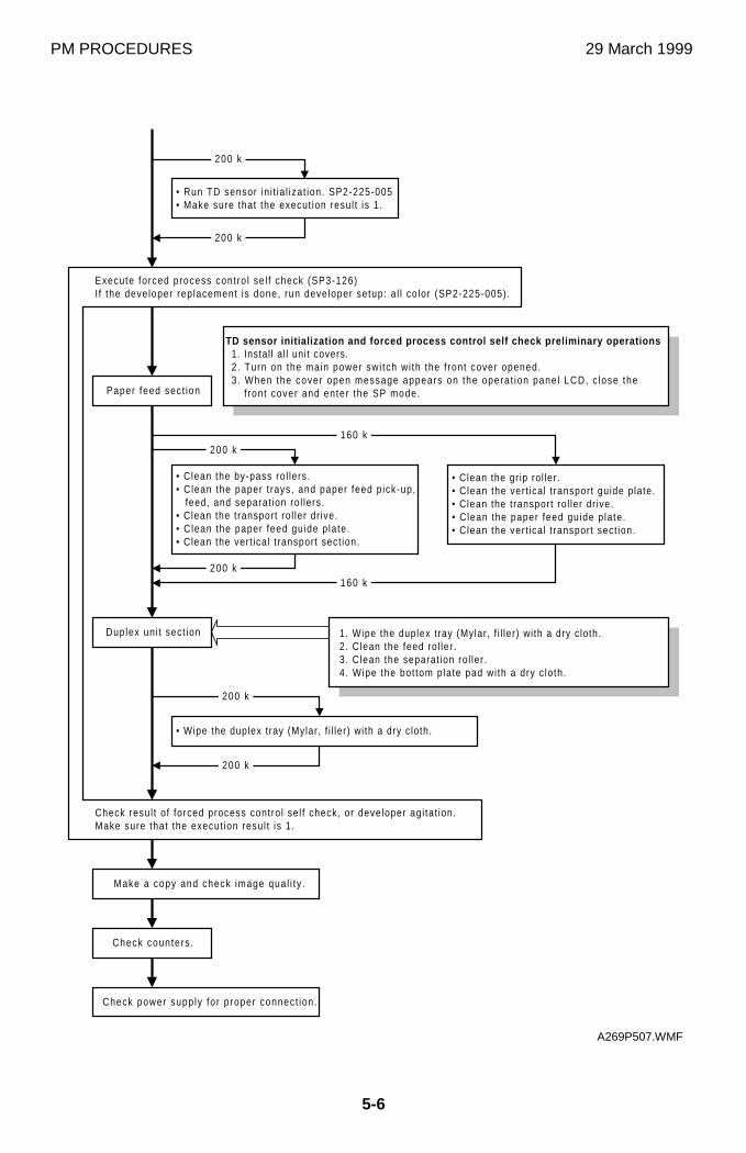
PM PROCEDURES 29 March 1999
5-6
• Wipe the duplex tray (Mylar, f i l ler) with a dry cloth.
200 k
200 k
TD sensor initialization and forced process control self check preliminary operations1. Instal l al l unit covers.2. Turn on the main power swi tch wi th the f ront cover opened.3 . When the cover open message appears on the operat ion panel LCD, c lose the
f ront cover and enter the SP mode.
Check power supply for proper connect ion.
Check counters .
����������
• Clean the gr ip rol ler.• Clean the vert ical t ransport guide plate.• Clean the transport rol ler dr ive.• Clean the paper feed guide p late.• Clean the vert ical t ransport sect ion.
• Clean the by-pass rol lers.• Clean the paper t rays, and paper feed p ick-up,
feed, and separat ion rol lers.• Clean the transport rol ler dr ive.• Clean the paper feed guide p late.• Clean the vert ical t ransport sect ion.
200 k
200 k
Paper feed sect ion
• Run TD sensor in i t ia l izat ion. SP2-225-005• Make sure that the execut ion resul t is 1.
160 k
160 k
200 k
200 k
1. Wipe the duplex tray (Mylar, f i l ler) with a dry cloth.2. Clean the feed rol ler .3. Clean the separat ion rol ler .4. Wipe the bot tom plate pad wi th a dry c loth.
Make a copy and check image qual i ty .
Check resul t of forced process contro l sel f check, or developer agi tat ion.Make sure that the execut ion resul t is 1.
Execute forced process contro l se l f check (SP3-126)I f the developer replacement is done, run developer setup: a l l co lor (SP2-225-005).
Duplex uni t sect ion
A269P507.WMF
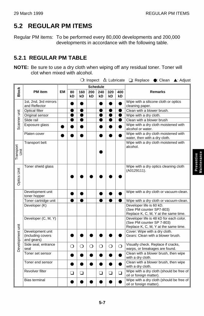
29 March 1999 REGULAR PM ITEMS
5-7
Pre
vent
ive
Mai
nten
ance
5.2 REGULAR PM ITEMS
Regular PM items: To be performed every 80,000 developments and 200,000developments in accordance with the following table.
5.2.1 REGULAR PM TABLE
NOTE: Be sure to use a dry cloth when wiping off any residual toner. Toner willclot when mixed with alcohol.
P: Inspect ∆: Lubricate T: Replace O: Clean V: Adjust
Schedule
Blo
ck PM item EM 80kD
160kD
200kD
240kD
320kD
400kD
Remarks
1st, 2nd, 3rd mirrorsand Reflector
O O O O OWipe with a silicone cloth or opticscleaning paper.
Optical filter O O O O O Clean with a blower brush.Original sensor O O O O O Wipe with a dry cloth.Slide rail O O O O O Clean with a blower brushExposure glass
O O O O O OWipe with a dry cloth moistened withalcohol or water.S
cann
er u
nit
Platen coverO O O O O O
Wipe with a dry cloth moistened withwater, then with a dry cloth.
Tra
nspo
rtU
nit
Transport belt
O
Wipe with a dry cloth moistened withalcohol.
Opt
ics
Uni
t Toner shield glass
O O O O O O
Wipe with a dry optics cleaning cloth(A0129111).
Development unittoner hopper
O O O O OWipe with a dry cloth or vacuum-clean.
Toner cartridge unit O O O O O Wipe with a dry cloth or vacuum-clean.Developer (K) Developer life is 60 kD.
(See PM counter SP7-803)Replace K, C, M, Y at the same time.
Developer (C, M, Y) Developer life is 48 kD for each color.(See PM counter SP 7-803)Replace K, C, M, Y at the same time.
Development unit(including coversand gears)
O O O O O OCover: Wipe with a dry cloth.Gears: Clean with a blower brush.
Side seal, entranceseal
P P P P P P Visually check. Replace if cracks,warps, or breakages are found.
Toner set sensorO O O O O O
Clean with a blower brush, then wipewith a dry cloth.
Toner end sensorO O O O O O
Clean with a blower brush, then wipewith a dry cloth.
Revolver filterT T T T T
Wipe with a dry cloth (should be free ofoil or foreign matter).
Dev
elop
men
t uni
t
Bias terminalO O O O O O
Wipe with a dry cloth (should be free ofoil or foreign matter).
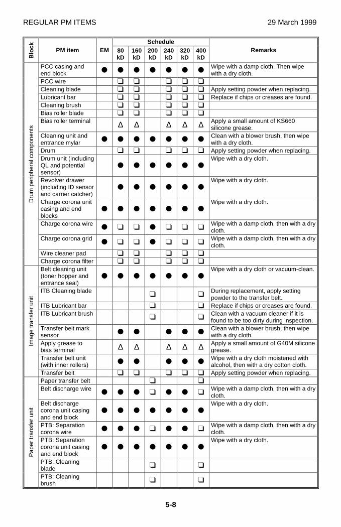
REGULAR PM ITEMS 29 March 1999
5-8
Schedule
Blo
ck PM item EM 80kD
160kD
200kD
240kD
320kD
400kD
Remarks
PCC casing andend block
O O O O O O OWipe with a damp cloth. Then wipewith a dry cloth.
PCC wire T T T T T
Cleaning blade T T T T T Apply setting powder when replacing.Lubricant bar T T T T T Replace if chips or creases are found.Cleaning brush T T T T T
Bias roller blade T T T T T
Bias roller terminal ∆ ∆ ∆ ∆ ∆ Apply a small amount of KS660silicone grease.
Cleaning unit andentrance mylar
O O O O O O OClean with a blower brush, then wipewith a dry cloth.
Drum T T T T T Apply setting powder when replacing.Drum unit (includingQL and potentialsensor)
O O O O O OWipe with a dry cloth.
Revolver drawer(including ID sensorand carrier catcher)
O O O O O OWipe with a dry cloth.
Charge corona unitcasing and endblocks
O O O O O O OWipe with a dry cloth.
Charge corona wireO T T O T T T
Wipe with a damp cloth, then with a drycloth.
Charge corona gridO T T O T T T
Wipe with a damp cloth, then with a drycloth.
Wire cleaner pad T T T T T
Dru
m p
erip
hera
l com
pone
nts
Charge corona filter T T T T T
Belt cleaning unit(toner hopper andentrance seal)
O O O O O O OWipe with a dry cloth or vacuum-clean.
ITB Cleaning bladeT T
During replacement, apply settingpowder to the transfer belt.
ITB Lubricant bar T T Replace if chips or creases are found.ITB Lubricant brush
T TClean with a vacuum cleaner if it isfound to be too dirty during inspection.
Transfer belt marksensor
O O O O OClean with a blower brush, then wipewith a dry cloth.
Apply grease tobias terminal ∆ ∆ ∆ ∆ ∆ Apply a small amount of G40M silicone
grease.Transfer belt unit(with inner rollers)
O O O O OWipe with a dry cloth moistened withalcohol, then with a dry cotton cloth.
Imag
e tr
ansf
er u
nit
Transfer belt T T T T T Apply setting powder when replacing.Paper transfer belt T T
Belt discharge wireO O O T O O T
Wipe with a damp cloth, then with a drycloth.
Belt dischargecorona unit casingand end block
O O O O O O OWipe with a dry cloth.
PTB: Separationcorona wire
O O O T O O TWipe with a damp cloth, then with a drycloth.
PTB: Separationcorona unit casingand end block
O O O O O O OWipe with a dry cloth.
PTB: Cleaningblade
T T
Pap
er tr
ansf
er u
nit
PTB: Cleaningbrush
T T
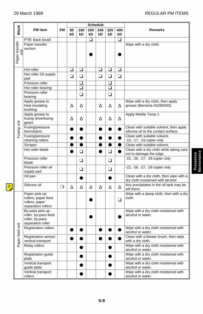
29 March 1999 REGULAR PM ITEMS
5-9
Pre
vent
ive
Mai
nten
ance
Schedule
Blo
ck PM item EM 80kD
160kD
200kD
240kD
320kD
400kD
Remarks
PTB: Back brush T T
Pap
er tr
ansf
erun
it
Paper transfersection
O O
Wipe with a dry cloth.
Hot roller T T T T T
Hot roller Oil supplypad
T T T T T
Pressure roller T T
Hot roller bearing T T
Pressure rollerbearing
T T
Apply grease toheat insulatingbushing
∆ ∆ ∆ ∆ ∆Wipe with a dry cloth, then applygrease (Barrierta A0289300).
Apply grease tofusing drive/fusinggears
∆ ∆ ∆ ∆ ∆Apply Mobile Temp 1.
Fusing/pressurethermistors
O O O O OClean with suitable solvent, then applysilicone oil to the contact surface.
Fusing/pressurecleaning rollers
O O O O OClean with suitable solvent.-15, -17, -19 copier only
Scraper O O O O O Clean with suitable solvent.Hot roller blade
O T O T OClean with a dry cloth while taking carenot to damage the edge.
Pressure rollerblade
T T-22, -26, -27, -29 copier only
Pressure roller oilsupply pad
T T-22, -26, -27, -29 copier only
Oil panO O
Clean with a dry cloth, then wipe with adry cloth moistened with alcohol.
Fus
ing
unit
Silicone oil P ∆ ∆ ∆ ∆ ∆ ∆ Any precipitates in the oil tank may beleft there.
Paper pick-uprollers, paper feedrollers, paperseparation rollers
O T
Wipe with a damp cloth, then with a drycloth.
By-pass pick-uproller, by-pass feedroller, by-passseparation roller
O O
Wipe with a dry cloth moistened withalcohol or water.
Registration rollersO O O O O
Wipe with a dry cloth moistened withalcohol or water.
Registration sensor:vertical transport
O O O O OClean with a blower brush, then wipewith a dry cloth.
Relay rollersO O
Wipe with a dry cloth moistened withalcohol or water.
Registration guideplate
O OWipe with a dry cloth moistened withalcohol or water.
Vertical transportguide plate
O OWipe with a dry cloth moistened withalcohol or water.
Pap
er fe
ed u
nit
Vertical transportrollers
O OWipe with a dry cloth moistened withalcohol or water.

REGULAR PM ITEMS 29 March 1999
5-10
Schedule
Blo
ck PM item EM 80kD
160kD
200kD
240kD
320kD
400kD
Remarks
Used toner tankP
O/T
O/T
PO/T
O/T
O/T
Collect used toner, then wipe thecontainers with a dry cloth, or replacethe used toner tank.
Exhaust dust filter T T T T TOth
ers
Fusing unit filter T T T T T
Paper feedseparation roller
O O O O TWipe with a damp cloth, then with a drycloth.
Paper feed rollerO O O O T
Wipe with a damp cloth, then with a drycloth.
Duplex bottom platepad
O O O O TWipe with a dry cloth.
Spring clutch ∆ ∆ ∆ ∆ ∆ Apply Mobile Temp 1.
Dup
lex
unit
Duplex unit O O O O O O Wipe with a dry cloth.
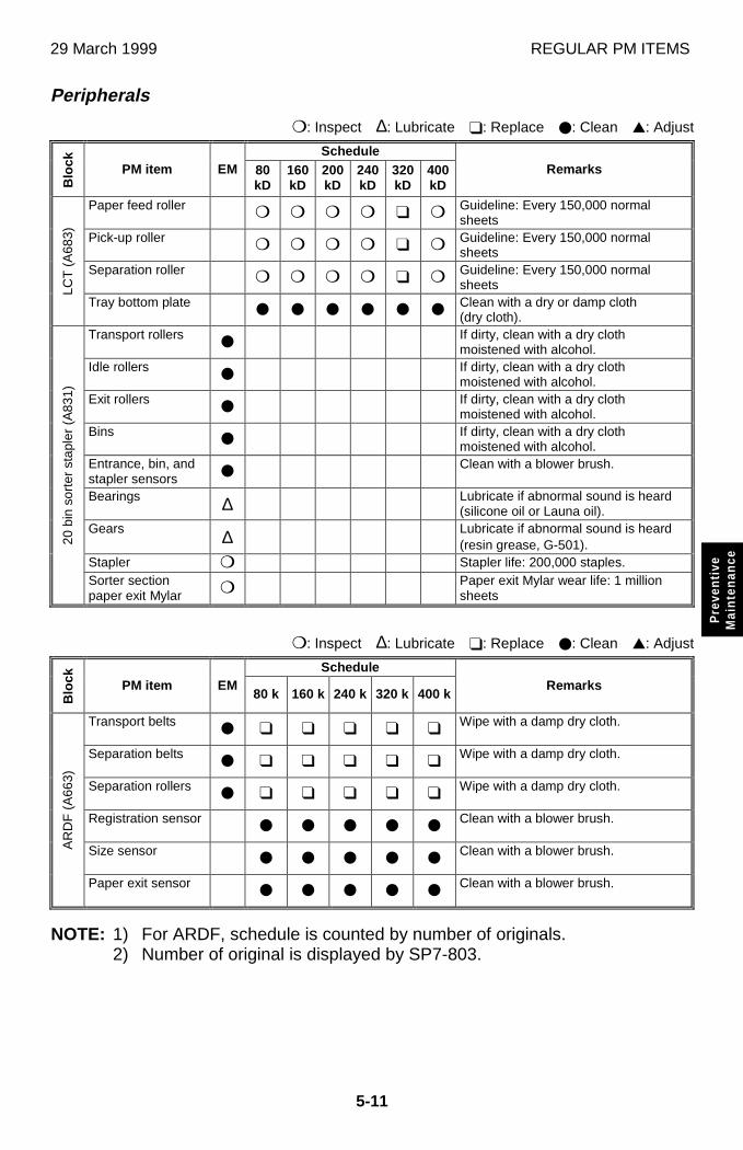
29 March 1999 REGULAR PM ITEMS
5-11
Pre
vent
ive
Mai
nten
ance
Peripherals
P: Inspect ∆: Lubricate T: Replace O: Clean V: Adjust
Schedule
Blo
ck PM item EM 80kD
160kD
200kD
240kD
320kD
400kD
Remarks
Paper feed roller P P P P T P Guideline: Every 150,000 normalsheets
Pick-up roller P P P P T P Guideline: Every 150,000 normalsheets
Separation roller P P P P T P Guideline: Every 150,000 normalsheetsLC
T (
A68
3)
Tray bottom plateO O O O O O
Clean with a dry or damp cloth(dry cloth).
Transport rollersO
If dirty, clean with a dry clothmoistened with alcohol.
Idle rollersO
If dirty, clean with a dry clothmoistened with alcohol.
Exit rollersO
If dirty, clean with a dry clothmoistened with alcohol.
BinsO
If dirty, clean with a dry clothmoistened with alcohol.
Entrance, bin, andstapler sensors
OClean with a blower brush.
Bearings ∆ Lubricate if abnormal sound is heard(silicone oil or Launa oil).
Gears ∆ Lubricate if abnormal sound is heard(resin grease, G-501).
Stapler P Stapler life: 200,000 staples.
20 b
in s
orte
r st
aple
r (A
831)
Sorter sectionpaper exit Mylar P Paper exit Mylar wear life: 1 million
sheets
P: Inspect ∆: Lubricate T: Replace O: Clean V: Adjust
Schedule
Blo
ck PM item EM80 k 160 k 240 k 320 k 400 k
Remarks
Transport beltsO T T T T T
Wipe with a damp dry cloth.
Separation beltsO T T T T T
Wipe with a damp dry cloth.
Separation rollersO T T T T T
Wipe with a damp dry cloth.
Registration sensorO O O O O
Clean with a blower brush.
Size sensorO O O O O
Clean with a blower brush.AR
DF
(A
663)
Paper exit sensorO O O O O
Clean with a blower brush.
NOTE: 1) For ARDF, schedule is counted by number of originals.2) Number of original is displayed by SP7-803.
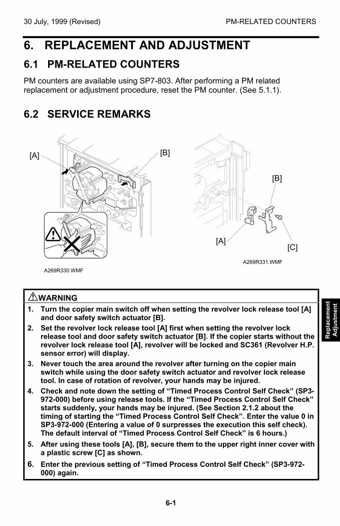
30 July, 1999 (Revised) PM-RELATED COUNTERS
6-1
Rep
lace
men
tA
dju
stm
ent
6. REPLACEMENT AND ADJUSTMENT
6.1 PM-RELATED COUNTERS
PM counters are available using SP7-803. After performing a PM relatedreplacement or adjustment procedure, reset the PM counter. (See 5.1.1).
6.2 SERVICE REMARKS
!WARNING1. Turn the copier main switch off when setting the revolver lock release tool [A]
and door safety switch actuator [B].
2. Set the revolver lock release tool [A] first when setting the revolver lockrelease tool and door safety switch actuator [B]. If the copier starts without therevolver lock release tool [A], revolver will be locked and SC361 (Revolver H.P.sensor error) will display.
3. Never touch the area around the revolver after turning on the copier mainswitch while using the door safety switch actuator and revolver lock releasetool. In case of rotation of revolver, your hands may be injured.
4. Check and note down the setting of “Timed Process Control Self Check” (SP3-972-000) before using release tools. If the “Timed Process Control Self Check”starts suddenly, your hands may be injured. (See Section 2.1.2 about thetiming of starting the “Timed Process Control Self Check”. Enter the value 0 inSP3-972-000 (Entering a value of 0 surpresses the execution this self check).The default interval of “Timed Process Control Self Check” is 6 hours.)
5. After using these tools [A], [B], secure them to the upper right inner cover witha plastic screw [C] as shown.
6. Enter the previous setting of “Timed Process Control Self Check” (SP3-972-000) again.
A269R331.WMF
A269R330.WMF
[B]
[A][C]
[A] [B]
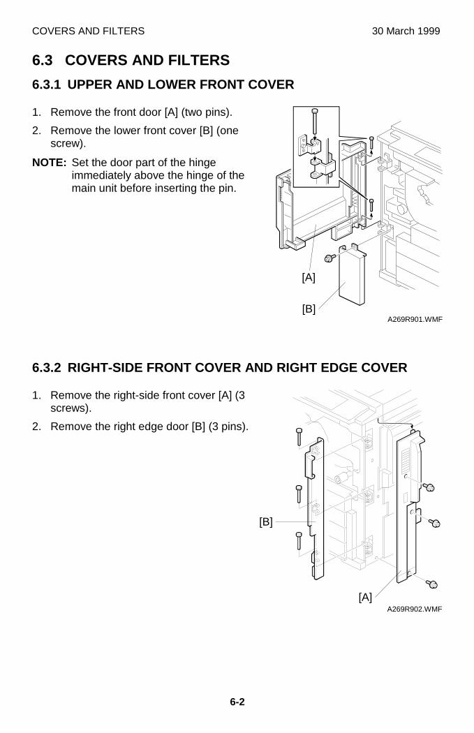
COVERS AND FILTERS 30 March 1999
6-2
6.3 COVERS AND FILTERS
6.3.1 UPPER AND LOWER FRONT COVER
1. Remove the front door [A] (two pins).
2. Remove the lower front cover [B] (onescrew).
NOTE: Set the door part of the hingeimmediately above the hinge of themain unit before inserting the pin.
6.3.2 RIGHT-SIDE FRONT COVER AND RIGHT EDGE COVER
1. Remove the right-side front cover [A] (3screws).
2. Remove the right edge door [B] (3 pins).
A269R901.WMF
A269R902.WMF
[A]
[B]
[A]
[B]
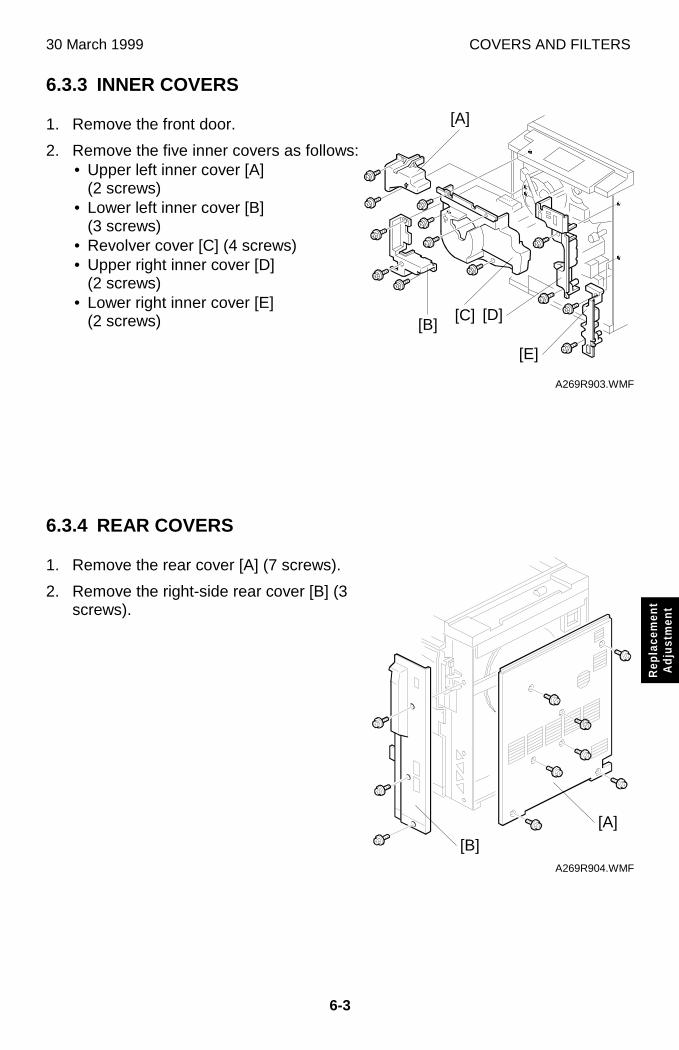
30 March 1999 COVERS AND FILTERS
6-3
Rep
lace
men
tA
djus
tmen
t
6.3.3 INNER COVERS
1. Remove the front door.
2. Remove the five inner covers as follows:• Upper left inner cover [A]
(2 screws)• Lower left inner cover [B]
(3 screws)• Revolver cover [C] (4 screws)• Upper right inner cover [D]
(2 screws)• Lower right inner cover [E]
(2 screws)
6.3.4 REAR COVERS
1. Remove the rear cover [A] (7 screws).
2. Remove the right-side rear cover [B] (3screws).
A269R903.WMF
A269R904.WMF
[C]
[E]
[B]
[D][B]
[A]
[A]
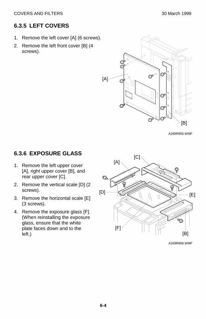
COVERS AND FILTERS 30 March 1999
6-4
6.3.5 LEFT COVERS
1. Remove the left cover [A] (6 screws).
2. Remove the left front cover [B] (4screws).
6.3.6 EXPOSURE GLASS
1. Remove the left upper cover[A], right upper cover [B], andrear upper cover [C].
2. Remove the vertical scale [D] (2screws).
3. Remove the horizontal scale [E](3 screws).
4. Remove the exposure glass [F].(When reinstalling the exposureglass, ensure that the whiteplate faces down and to theleft.)
A269R905.WMF
A269R906.WMF
[A]
[A]
[B]
[B]
[C]
[E][D]
[F]
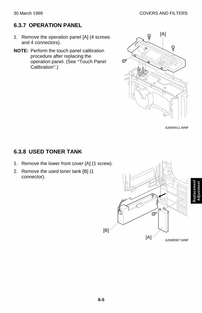
30 March 1999 COVERS AND FILTERS
6-5
Rep
lace
men
tA
djus
tmen
t
6.3.7 OPERATION PANEL
1. Remove the operation panel [A] (4 screwsand 4 connectors).
NOTE: Perform the touch panel calibrationprocedure after replacing theoperation panel. (See “Touch PanelCalibration” .)
6.3.8 USED TONER TANK
1. Remove the lower front cover [A] (1 screw).
2. Remove the used toner tank [B] (1connector).
A269R911.WMF
A269R907.WMF
[A]
[A]
[B]
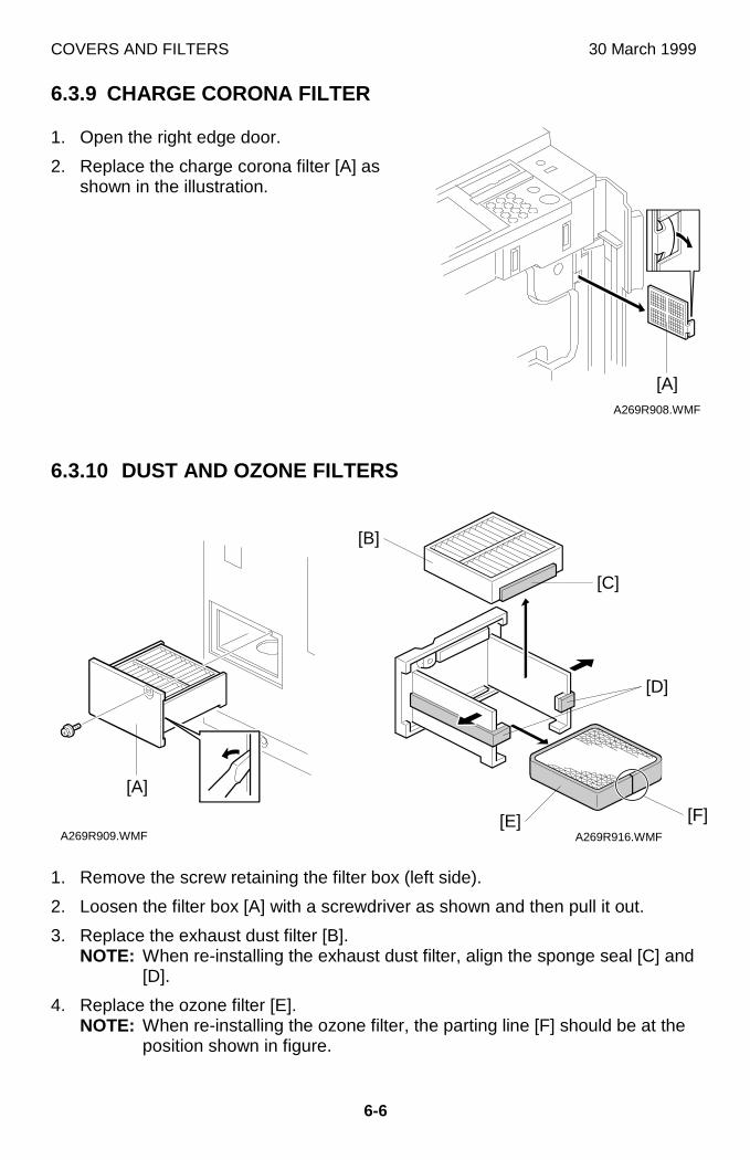
COVERS AND FILTERS 30 March 1999
6-6
6.3.9 CHARGE CORONA FILTER
1. Open the right edge door.
2. Replace the charge corona filter [A] asshown in the illustration.
6.3.10 DUST AND OZONE FILTERS
1. Remove the screw retaining the filter box (left side).
2. Loosen the filter box [A] with a screwdriver as shown and then pull it out.
3. Replace the exhaust dust filter [B].NOTE: When re-installing the exhaust dust filter, align the sponge seal [C] and
[D].
4. Replace the ozone filter [E].NOTE: When re-installing the ozone filter, the parting line [F] should be at the
position shown in figure.
A269R908.WMF
A269R909.WMF A269R916.WMF
[A]
[A]
[D]
[C]
[B]
[E] [F]
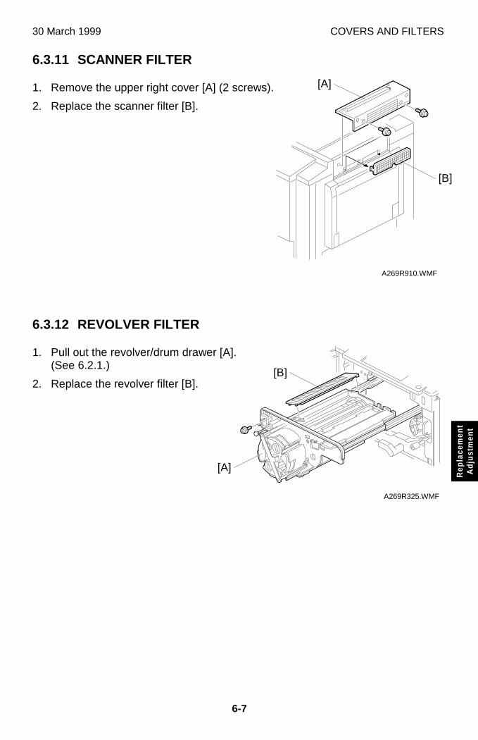
30 March 1999 COVERS AND FILTERS
6-7
Rep
lace
men
tA
djus
tmen
t
6.3.11 SCANNER FILTER
1. Remove the upper right cover [A] (2 screws).
2. Replace the scanner filter [B].
6.3.12 REVOLVER FILTER
1. Pull out the revolver/drum drawer [A].(See 6.2.1.)
2. Replace the revolver filter [B].
A269R910.WMF
A269R325.WMF
[A]
[A]
[B]
[B]
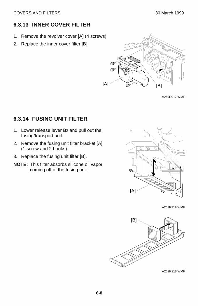
COVERS AND FILTERS 30 March 1999
6-8
6.3.13 INNER COVER FILTER
1. Remove the revolver cover [A] (4 screws).
2. Replace the inner cover filter [B].
6.3.14 FUSING UNIT FILTER
1. Lower release lever B2 and pull out thefusing/transport unit.
2. Remove the fusing unit filter bracket [A](1 screw and 2 hooks).
3. Replace the fusing unit filter [B].
NOTE: This filter absorbs silicone oil vaporcoming off of the fusing unit.
A269R917.WMF
A269R919.WMF
A269R918.WMF
[A]
[A]
[B]
[B]
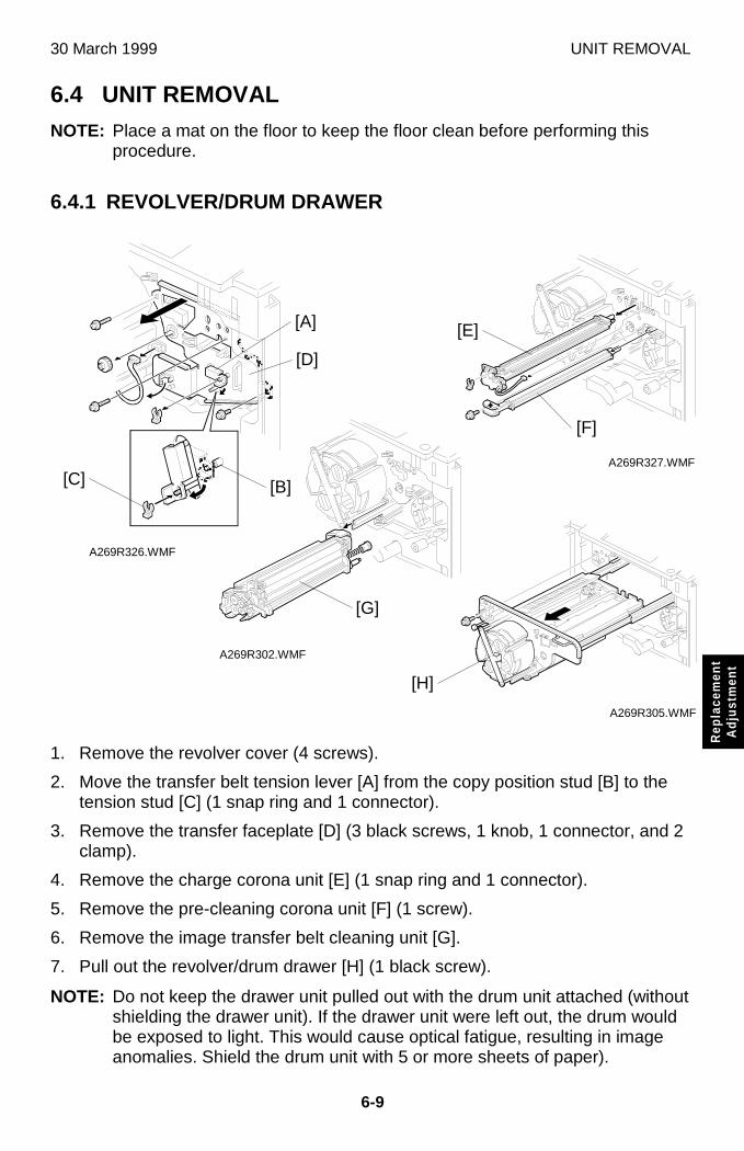
30 March 1999 UNIT REMOVAL
6-9
Rep
lace
men
tA
djus
tmen
t
6.4 UNIT REMOVALNOTE: Place a mat on the floor to keep the floor clean before performing this
procedure.
6.4.1 REVOLVER/DRUM DRAWER
1. Remove the revolver cover (4 screws).
2. Move the transfer belt tension lever [A] from the copy position stud [B] to thetension stud [C] (1 snap ring and 1 connector).
3. Remove the transfer faceplate [D] (3 black screws, 1 knob, 1 connector, and 2clamp).
4. Remove the charge corona unit [E] (1 snap ring and 1 connector).
5. Remove the pre-cleaning corona unit [F] (1 screw).
6. Remove the image transfer belt cleaning unit [G].
7. Pull out the revolver/drum drawer [H] (1 black screw).
NOTE: Do not keep the drawer unit pulled out with the drum unit attached (withoutshielding the drawer unit). If the drawer unit were left out, the drum wouldbe exposed to light. This would cause optical fatigue, resulting in imageanomalies. Shield the drum unit with 5 or more sheets of paper).
A269R327.WMF
A269R326.WMF
A269R302.WMF
A269R305.WMF
[D]
[F]
[G]
[H]
[B][C]
[A] [E]
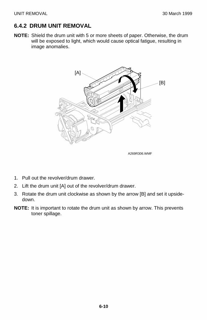
UNIT REMOVAL 30 March 1999
6-10
6.4.2 DRUM UNIT REMOVAL
NOTE: Shield the drum unit with 5 or more sheets of paper. Otherwise, the drumwill be exposed to light, which would cause optical fatigue, resulting inimage anomalies.
1. Pull out the revolver/drum drawer.
2. Lift the drum unit [A] out of the revolver/drum drawer.
3. Rotate the drum unit clockwise as shown by the arrow [B] and set it upside-down.
NOTE: It is important to rotate the drum unit as shown by arrow. This preventstoner spillage.
A269R306.WMF
[A]
[B]
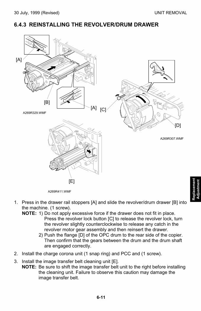
30 July, 1999 (Revised) UNIT REMOVAL
6-11
Rep
lace
men
tA
dju
stm
ent
6.4.3 REINSTALLING THE REVOLVER/DRUM DRAWER
1. Press in the drawer rail stoppers [A] and slide the revolver/drum drawer [B] intothe machine. (1 screw).NOTE: 1) Do not apply excessive force if the drawer does not fit in place.
Press the revolver lock button [C] to release the revolver lock, turnthe revolver slightly counterclockwise to release any catch in therevolver motor gear assembly and then reinsert the drawer.
2) Push the flange [D] of the OPC drum to the rear side of the copier.Then confirm that the gears between the drum and the drum shaftare engaged correctly.
2. Install the charge corona unit (1 snap ring) and PCC and (1 screw).
3. Install the image transfer belt cleaning unit [E].NOTE: Be sure to shift the image transfer belt unit to the right before installing
the cleaning unit. Failure to observe this caution may damage theimage transfer belt.
A269R329.WMF
A269R307.WMF
A269R411.WMF
[B][A] [C]
[A]
[D]
[E]
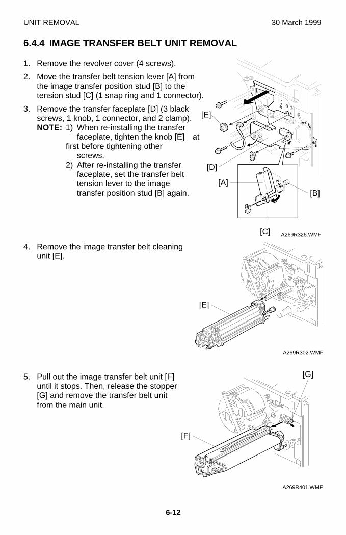
UNIT REMOVAL 30 March 1999
6-12
6.4.4 IMAGE TRANSFER BELT UNIT REMOVAL
1. Remove the revolver cover (4 screws).
2. Move the transfer belt tension lever [A] fromthe image transfer position stud [B] to thetension stud [C] (1 snap ring and 1 connector).
3. Remove the transfer faceplate [D] (3 blackscrews, 1 knob, 1 connector, and 2 clamp).NOTE: 1) When re-installing the transfer
faceplate, tighten the knob [E] atfirst before tightening other
screws.2) After re-installing the transfer
faceplate, set the transfer belttension lever to the imagetransfer position stud [B] again.
4. Remove the image transfer belt cleaningunit [E].
5. Pull out the image transfer belt unit [F]until it stops. Then, release the stopper[G] and remove the transfer belt unitfrom the main unit.
A269R326.WMF
A269R302.WMF
A269R401.WMF
[C]
[B]
[E]
[F]
[A]
[D]
[G]
[E]
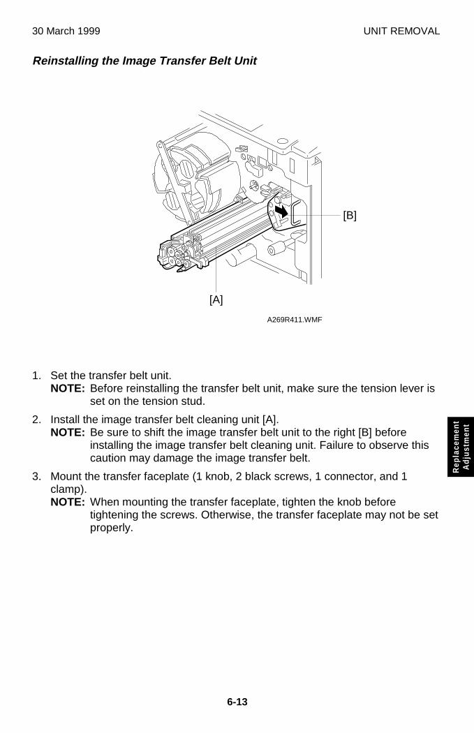
30 March 1999 UNIT REMOVAL
6-13
Rep
lace
men
tA
djus
tmen
t
Reinstalling the Image Transfer Belt Unit
1. Set the transfer belt unit.NOTE: Before reinstalling the transfer belt unit, make sure the tension lever is
set on the tension stud.
2. Install the image transfer belt cleaning unit [A].NOTE: Be sure to shift the image transfer belt unit to the right [B] before
installing the image transfer belt cleaning unit. Failure to observe thiscaution may damage the image transfer belt.
3. Mount the transfer faceplate (1 knob, 2 black screws, 1 connector, and 1clamp).NOTE: When mounting the transfer faceplate, tighten the knob before
tightening the screws. Otherwise, the transfer faceplate may not be setproperly.
A269R411.WMF
[A]
[B]
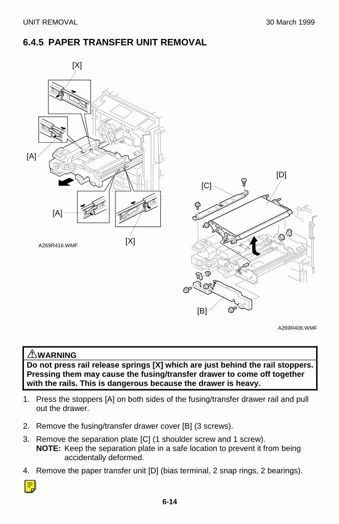
UNIT REMOVAL 30 March 1999
6-14
6.4.5 PAPER TRANSFER UNIT REMOVAL
øWARNINGDo not press rail release springs [X] which are just behind the rail stoppers.Pressing them may cause the fusing/transfer drawer to come off togetherwith the rails. This is dangerous because the drawer is heavy.
1. Press the stoppers [A] on both sides of the fusing/transfer drawer rail and pullout the drawer.
2. Remove the fusing/transfer drawer cover [B] (3 screws).
3. Remove the separation plate [C] (1 shoulder screw and 1 screw).NOTE: Keep the separation plate in a safe location to prevent it from being
accidentally deformed.
4. Remove the paper transfer unit [D] (bias terminal, 2 snap rings, 2 bearings).
A269R416.WMF
A269R406.WMF
[X]
[A]
[D][C]
[A]
[X]
[B]
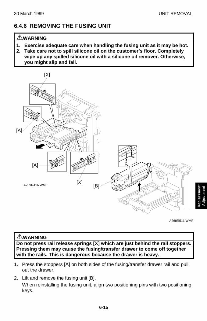
30 March 1999 UNIT REMOVAL
6-15
Rep
lace
men
tA
djus
tmen
t
6.4.6 REMOVING THE FUSING UNIT
øWARNING1. Exercise adequate care when handling the fusing unit as it may be hot.2. Take care not to spill silicone oil on the customer’s floor. Completely
wipe up any spilled silicone oil with a silicone oil remover. Otherwise,you might slip and fall.
øWARNINGDo not press rail release springs [X] which are just behind the rail stoppers.Pressing them may cause the fusing/transfer drawer to come off togetherwith the rails. This is dangerous because the drawer is heavy.
1. Press the stoppers [A] on both sides of the fusing/transfer drawer rail and pullout the drawer.
2. Lift and remove the fusing unit [B].When reinstalling the fusing unit, align two positioning pins with two positioningkeys.
A269R416.WMF
A269R511.WMF
[B]
[X]
[A]
[A]
[X]
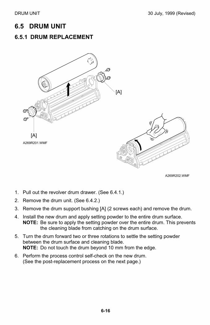
DRUM UNIT 30 July, 1999 (Revised)
6-16
6.5 DRUM UNIT
6.5.1 DRUM REPLACEMENT
1. Pull out the revolver drum drawer. (See 6.4.1.)
2. Remove the drum unit. (See 6.4.2.)
3. Remove the drum support bushing [A] (2 screws each) and remove the drum.
4. Install the new drum and apply setting powder to the entire drum surface.NOTE: Be sure to apply the setting powder over the entire drum. This prevents
the cleaning blade from catching on the drum surface.
5. Turn the drum forward two or three rotations to settle the setting powderbetween the drum surface and cleaning blade.NOTE: Do not touch the drum beyond 10 mm from the edge.
6. Perform the process control self-check on the new drum.(See the post-replacement process on the next page.)
A269R201.WMF
A269R202.WMF
[A]
[A]
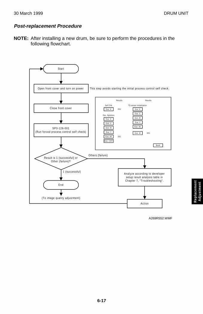
30 March 1999 DRUM UNIT
6-17
Rep
lace
men
tA
djus
tmen
t
Post-replacement Procedure
NOTE: After installing a new drum, be sure to perform the procedures in thefollowing flowchart.
Start
Open front cover and turn on power
Close front cover
SP3-126-001(Run forced process control sel f check)
Result is 1 (successful) orOther (fai lure)?
End
Analyze according to developersetup result analysis table in
Chapter 7, "Troubleshoot ing".
Act ion
1 (successful)
Others (fai lure)
This step avoids start ing the ini t ia l process control sel f check.
(To image qual i ty adjusrment)
Back
Exe: K
Exe: C
Exe: M
Exe: All
Exe: CMY
Dev. Agitation
Exe: K
Self Chk
001
Exe: Y
001
Results
Exe: K
Exe: C
Exe: M
Exe: Y
Exe: All
TD sensor initialization
Exe: M 001
Results
A269R552.WMF
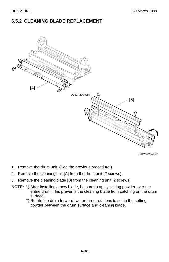
DRUM UNIT 30 March 1999
6-18
6.5.2 CLEANING BLADE REPLACEMENT
1. Remove the drum unit. (See the previous procedure.)
2. Remove the cleaning unit [A] from the drum unit (2 screws).
3. Remove the cleaning blade [B] from the cleaning unit (2 screws).
NOTE: 1) After installing a new blade, be sure to apply setting powder over theentire drum. This prevents the cleaning blade from catching on the drumsurface.
2) Rotate the drum forward two or three rotations to settle the settingpowder between the drum surface and cleaning blade.
A269R206.WMF
A269R204.WMF
[A]
[B]
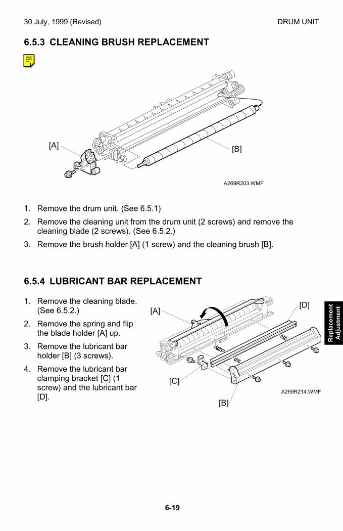
30 July, 1999 (Revised) DRUM UNIT
6-19
Rep
lace
men
tA
dju
stm
ent
6.5.3 CLEANING BRUSH REPLACEMENT
1. Remove the drum unit. (See 6.5.1)
2. Remove the cleaning unit from the drum unit (2 screws) and remove thecleaning blade (2 screws). (See 6.5.2.)
3. Remove the brush holder [A] (1 screw) and the cleaning brush [B].
6.5.4 LUBRICANT BAR REPLACEMENT
1. Remove the cleaning blade.(See 6.5.2.)
2. Remove the spring and flipthe blade holder [A] up.
3. Remove the lubricant barholder [B] (3 screws).
4. Remove the lubricant barclamping bracket [C] (1screw) and the lubricant bar[D].
A269R203.WMF
A269R214.WMF
[A] [B]
[A][D]
[B]
[C]
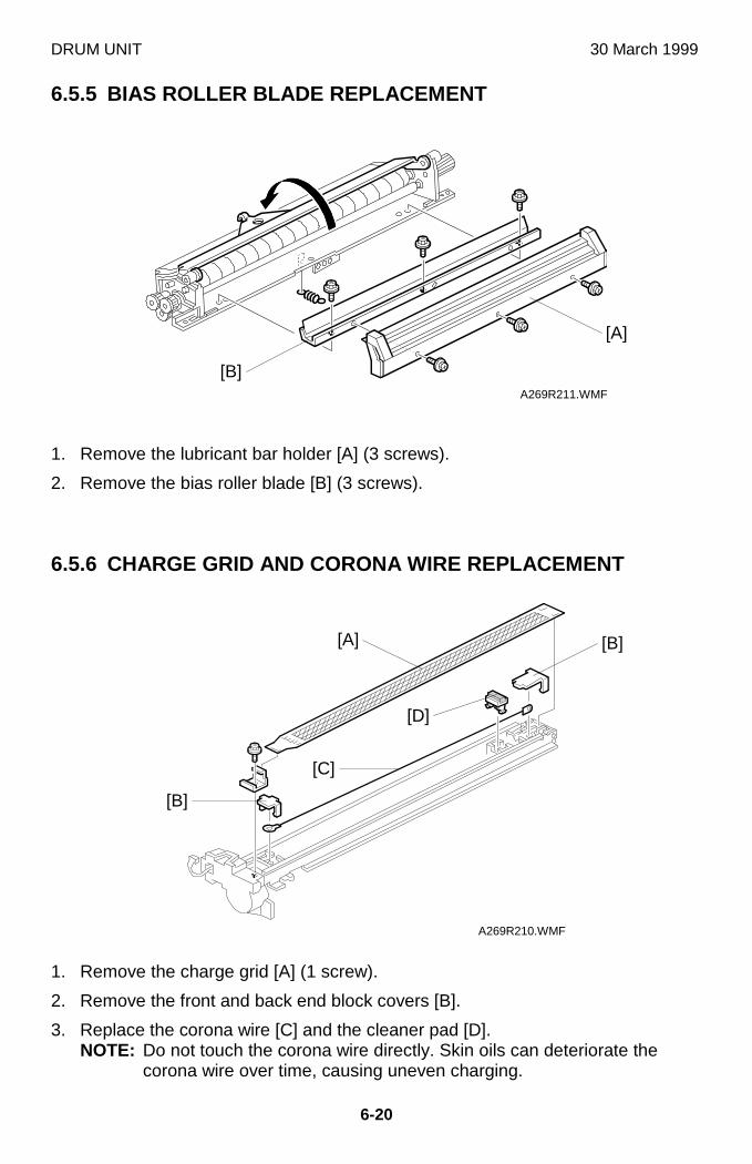
DRUM UNIT 30 March 1999
6-20
6.5.5 BIAS ROLLER BLADE REPLACEMENT
1. Remove the lubricant bar holder [A] (3 screws).
2. Remove the bias roller blade [B] (3 screws).
6.5.6 CHARGE GRID AND CORONA WIRE REPLACEMENT
1. Remove the charge grid [A] (1 screw).
2. Remove the front and back end block covers [B].
3. Replace the corona wire [C] and the cleaner pad [D].NOTE: Do not touch the corona wire directly. Skin oils can deteriorate the
corona wire over time, causing uneven charging.
A269R211.WMF
A269R210.WMF
[A] [B]
[D]
[C]
[B]
[A]
[B]
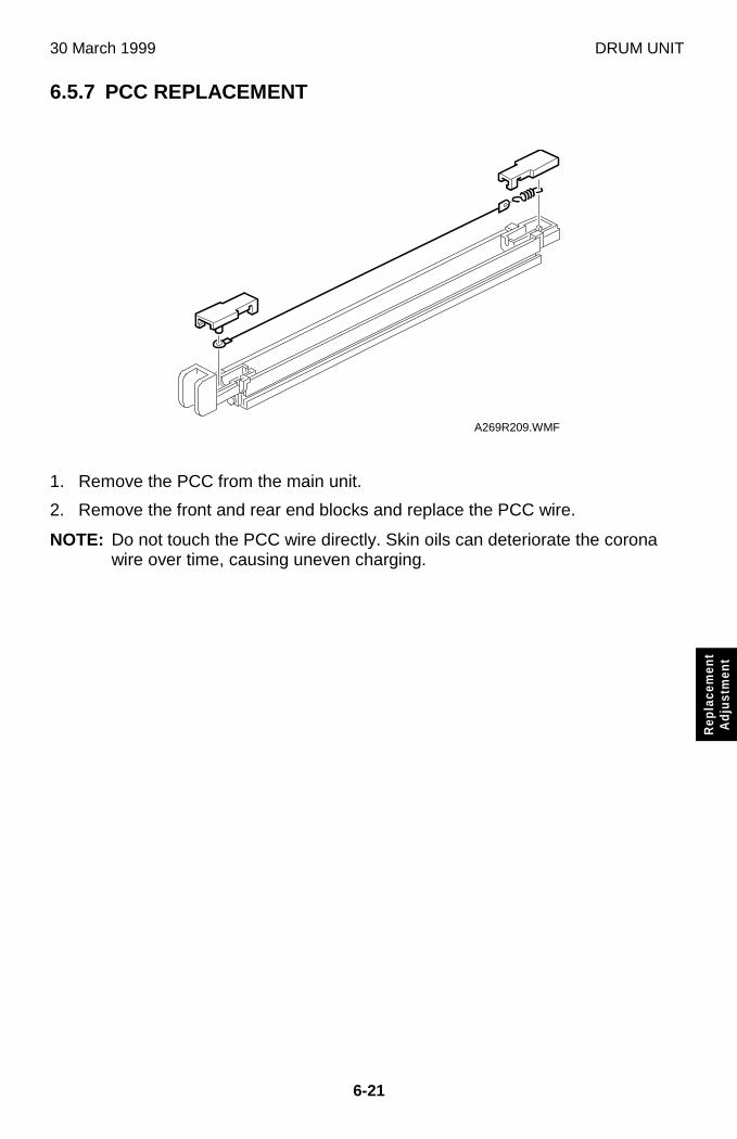
30 March 1999 DRUM UNIT
6-21
Rep
lace
men
tA
djus
tmen
t
6.5.7 PCC REPLACEMENT
1. Remove the PCC from the main unit.
2. Remove the front and rear end blocks and replace the PCC wire.
NOTE: Do not touch the PCC wire directly. Skin oils can deteriorate the coronawire over time, causing uneven charging.
A269R209.WMF
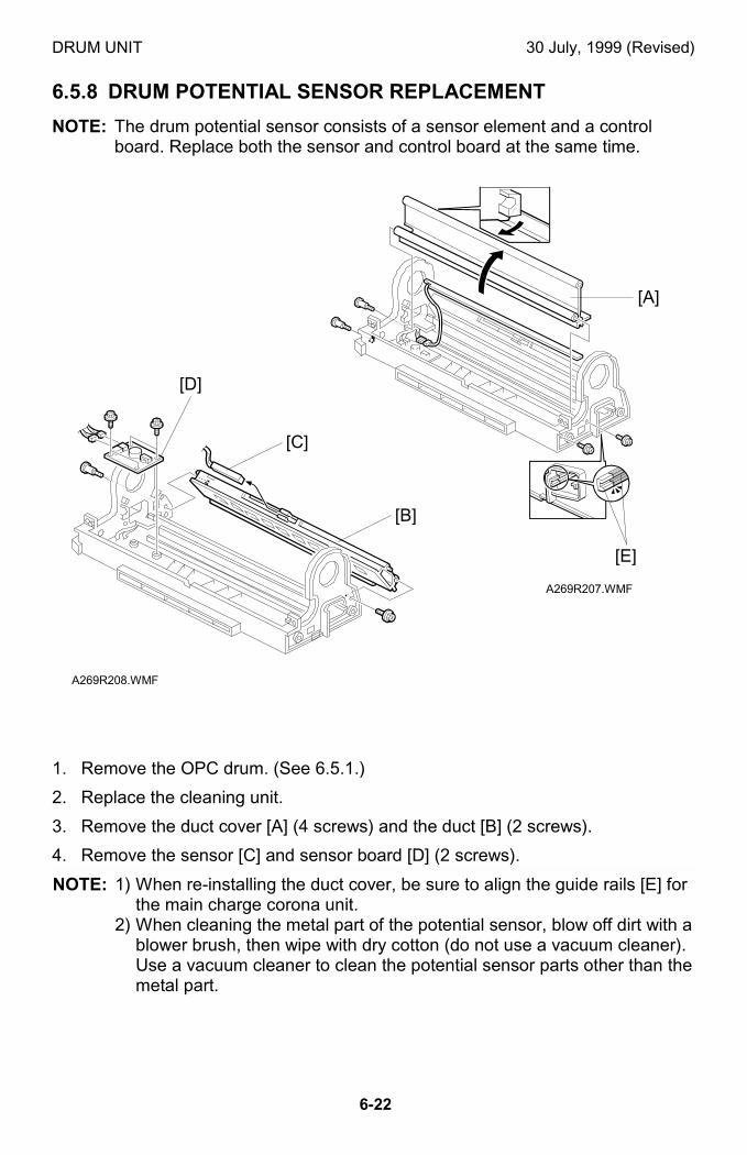
DRUM UNIT 30 July, 1999 (Revised)
6-22
6.5.8 DRUM POTENTIAL SENSOR REPLACEMENT
NOTE: The drum potential sensor consists of a sensor element and a controlboard. Replace both the sensor and control board at the same time.
1. Remove the OPC drum. (See 6.5.1.)
2. Replace the cleaning unit.
3. Remove the duct cover [A] (4 screws) and the duct [B] (2 screws).
4. Remove the sensor [C] and sensor board [D] (2 screws).
NOTE: 1) When re-installing the duct cover, be sure to align the guide rails [E] forthe main charge corona unit.
2) When cleaning the metal part of the potential sensor, blow off dirt with ablower brush, then wipe with dry cotton (do not use a vacuum cleaner).Use a vacuum cleaner to clean the potential sensor parts other than themetal part.
A269R207.WMF
A269R208.WMF
[B]
[D]
[C]
[A]
[E]
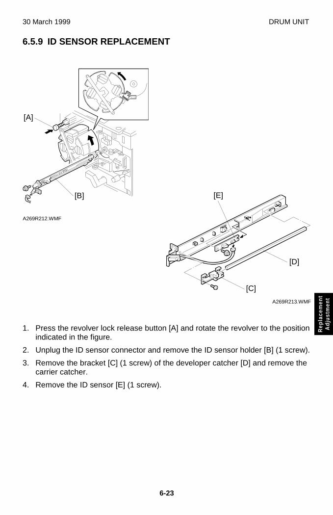
30 March 1999 DRUM UNIT
6-23
Rep
lace
men
tA
djus
tmen
t
6.5.9 ID SENSOR REPLACEMENT
1. Press the revolver lock release button [A] and rotate the revolver to the positionindicated in the figure.
2. Unplug the ID sensor connector and remove the ID sensor holder [B] (1 screw).
3. Remove the bracket [C] (1 screw) of the developer catcher [D] and remove thecarrier catcher.
4. Remove the ID sensor [E] (1 screw).
A269R212.WMF
A269R213.WMF
[A]
[C]
[D]
[B] [E]
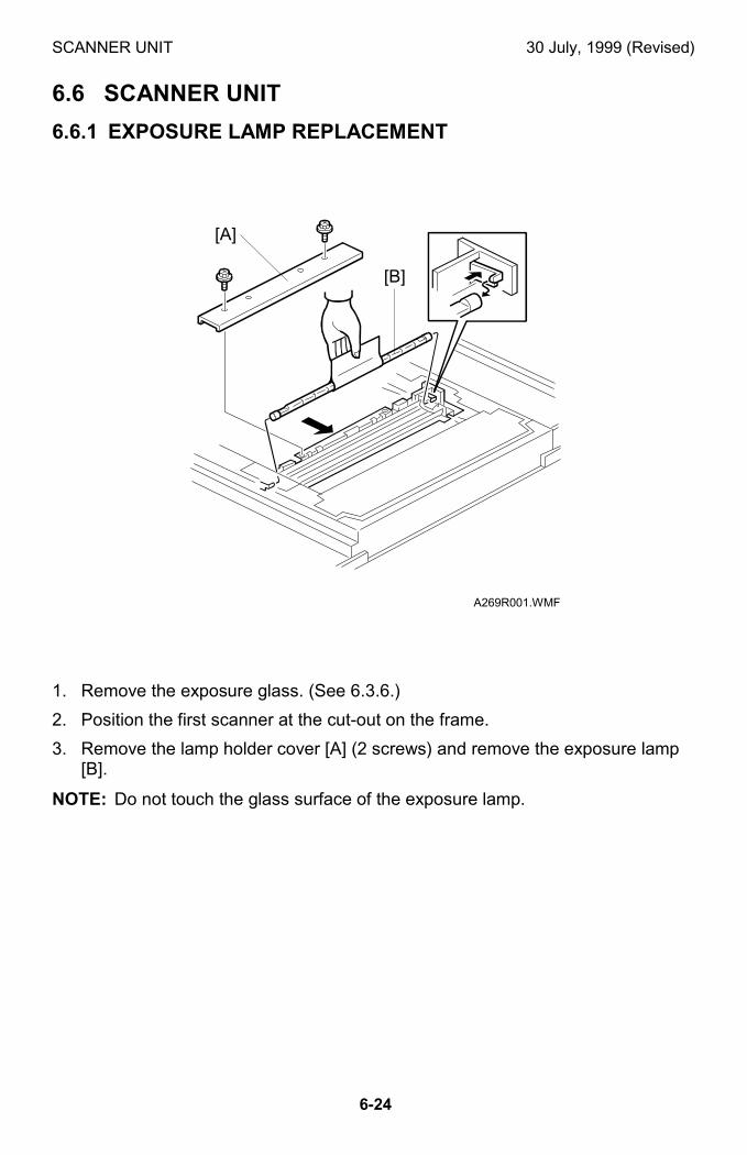
SCANNER UNIT 30 July, 1999 (Revised)
6-24
6.6 SCANNER UNIT
6.6.1 EXPOSURE LAMP REPLACEMENT
1. Remove the exposure glass. (See 6.3.6.)
2. Position the first scanner at the cut-out on the frame.
3. Remove the lamp holder cover [A] (2 screws) and remove the exposure lamp[B].
NOTE: Do not touch the glass surface of the exposure lamp.
A269R001.WMF
[A]
[B]
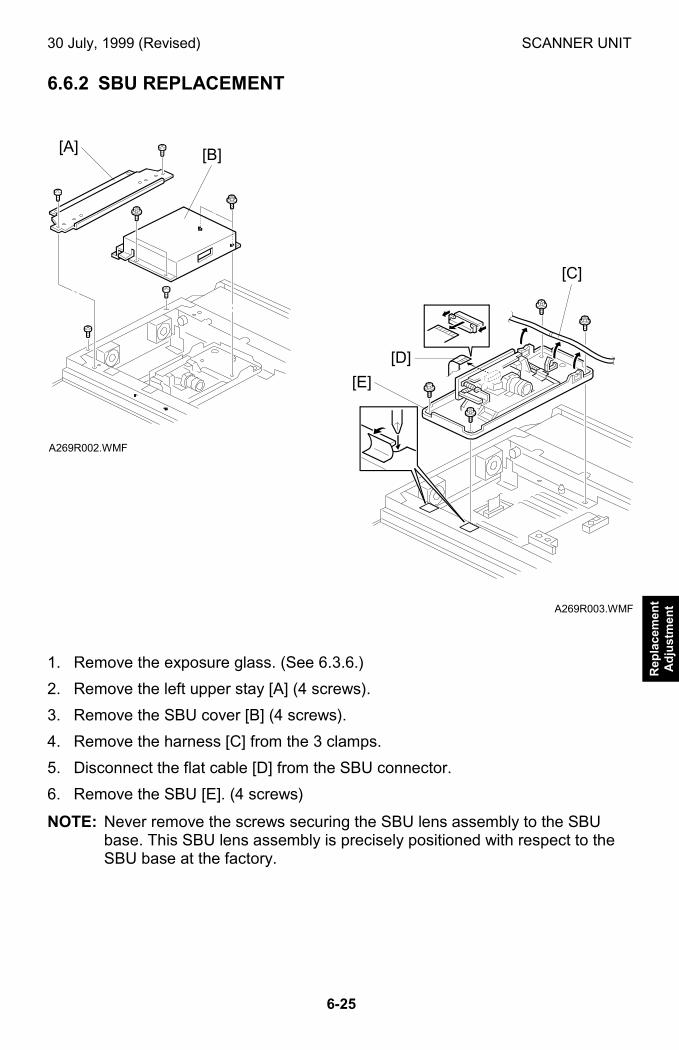
30 July, 1999 (Revised) SCANNER UNIT
6-25
Rep
lace
men
tA
dju
stm
ent
6.6.2 SBU REPLACEMENT
1. Remove the exposure glass. (See 6.3.6.)
2. Remove the left upper stay [A] (4 screws).
3. Remove the SBU cover [B] (4 screws).
4. Remove the harness [C] from the 3 clamps.
5. Disconnect the flat cable [D] from the SBU connector.
6. Remove the SBU [E]. (4 screws)
NOTE: Never remove the screws securing the SBU lens assembly to the SBUbase. This SBU lens assembly is precisely positioned with respect to theSBU base at the factory.
A269R002.WMF
A269R003.WMF
[A]
[D]
[E]
[B]
[C]
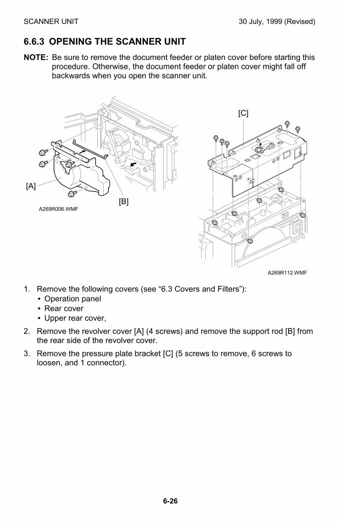
SCANNER UNIT 30 July, 1999 (Revised)
6-26
6.6.3 OPENING THE SCANNER UNIT
NOTE: Be sure to remove the document feeder or platen cover before starting thisprocedure. Otherwise, the document feeder or platen cover might fall offbackwards when you open the scanner unit.
1. Remove the following covers (see “6.3 Covers and Filters”):• Operation panel• Rear cover• Upper rear cover,
2. Remove the revolver cover [A] (4 screws) and remove the support rod [B] fromthe rear side of the revolver cover.
3. Remove the pressure plate bracket [C] (5 screws to remove, 6 screws toloosen, and 1 connector).
A269R112.WMF
A269R006.WMF
[A]
[C]
[B]
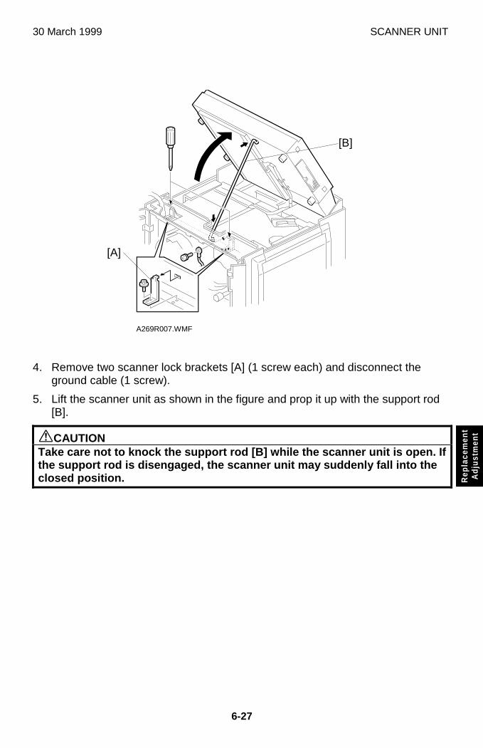
30 March 1999 SCANNER UNIT
6-27
Rep
lace
men
tA
djus
tmen
t
4. Remove two scanner lock brackets [A] (1 screw each) and disconnect theground cable (1 screw).
5. Lift the scanner unit as shown in the figure and prop it up with the support rod[B].
øCAUTIONTake care not to knock the support rod [B] while the scanner unit is open. Ifthe support rod is disengaged, the scanner unit may suddenly fall into theclosed position.
A269R007.WMF
[A]
[B]
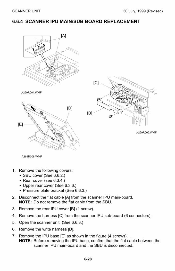
SCANNER UNIT 30 July, 1999 (Revised)
6-28
6.6.4 SCANNER IPU MAIN/SUB BOARD REPLACEMENT
1. Remove the following covers:• SBU cover (See 6.6.2.)• Rear cover (see 6.3.4.)• Upper rear cover (See 6.3.6.)• Pressure plate bracket (See 6.6.3.)
2. Disconnect the flat cable [A] from the scanner IPU main-board.NOTE: Do not remove the flat cable from the SBU.
3. Remove the rear IPU cover [B] (1 screw).
4. Remove the harness [C] from the scanner IPU sub-board (6 connectors).
5. Open the scanner unit. (See 6.6.3.)
6. Remove the write harness [D].
7. Remove the IPU base [E] as shown in the figure (4 screws).NOTE: Before removing the IPU base, confirm that the flat cable between the
scanner IPU main-board and the SBU is disconnected.
A269R004.WMF
A269R005.WMF
A269R008.WMF
[A]
[C]
[E]
[D][B]
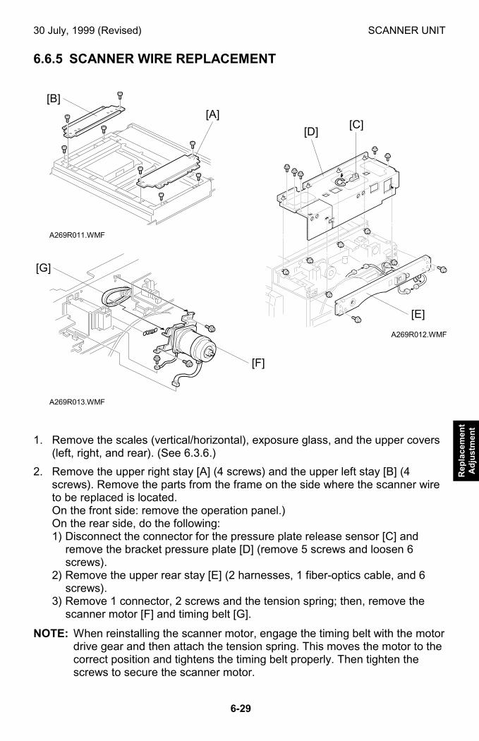
30 July, 1999 (Revised) SCANNER UNIT
6-29
Rep
lace
men
tA
dju
stm
ent
6.6.5 SCANNER WIRE REPLACEMENT
1. Remove the scales (vertical/horizontal), exposure glass, and the upper covers(left, right, and rear). (See 6.3.6.)
2. Remove the upper right stay [A] (4 screws) and the upper left stay [B] (4screws). Remove the parts from the frame on the side where the scanner wireto be replaced is located.On the front side: remove the operation panel.)On the rear side, do the following:1) Disconnect the connector for the pressure plate release sensor [C] and
remove the bracket pressure plate [D] (remove 5 screws and loosen 6screws).
2) Remove the upper rear stay [E] (2 harnesses, 1 fiber-optics cable, and 6screws).
3) Remove 1 connector, 2 screws and the tension spring; then, remove thescanner motor [F] and timing belt [G].
NOTE: When reinstalling the scanner motor, engage the timing belt with the motordrive gear and then attach the tension spring. This moves the motor to thecorrect position and tightens the timing belt properly. Then tighten thescrews to secure the scanner motor.
A269R011.WMF
A269R012.WMF
A269R013.WMF
[B]
[A]
[E]
[D]
[F]
[C]
[G]
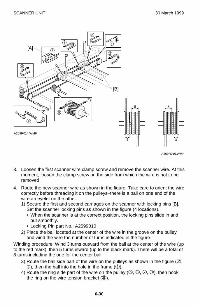
SCANNER UNIT 30 March 1999
6-30
3. Loosen the first scanner wire clamp screw and remove the scanner wire. At thismoment, loosen the clamp screw on the side from which the wire is not to beremoved.
4. Route the new scanner wire as shown in the figure. Take care to orient the wirecorrectly before threading it on the pulleys–there is a ball on one end of thewire an eyelet on the other.1) Secure the first and second carriages on the scanner with locking pins [B].
Set the scanner locking pins as shown in the figure (4 locations).• When the scanner is at the correct position, the locking pins slide in and
out smoothly.• Locking Pin part No.: A2599010
2) Place the ball located at the center of the wire in the groove on the pulleyand wind the wire the number of turns indicated in the figure.
Winding procedure: Wind 3 turns outward from the ball at the center of the wire (upto the red mark), then 5 turns inward (up to the black mark). There will be a total of8 turns including the one for the center ball.
3) Route the ball side part of the wire on the pulleys as shown in the figure (�,�), then the ball into the hole in the frame (�).
4) Route the ring side part of the wire on the pulley (�, �, �, �), then hookthe ring on the wire tension bracket (�).
A269R014.WMF
A269R016.WMF
[A]
[B]
30 March 1999 SCANNER UNIT
6-31
Rep
lace
men
tA
djus
tmen
t
5. Hook the spring on the wire tension bracket and tighten the screw permanently.
6. Clamp the wire.
7. Remove the scanner locking pins.
8. Replace all parts except those removed in step 1.
9. After tensioning the wire by executing a scanner free run (SP 4-013-0022),reset the scanner locking pins, then loosen and reset the scanner wire clamp.
10. Assemble in the reverse order of disassembly.
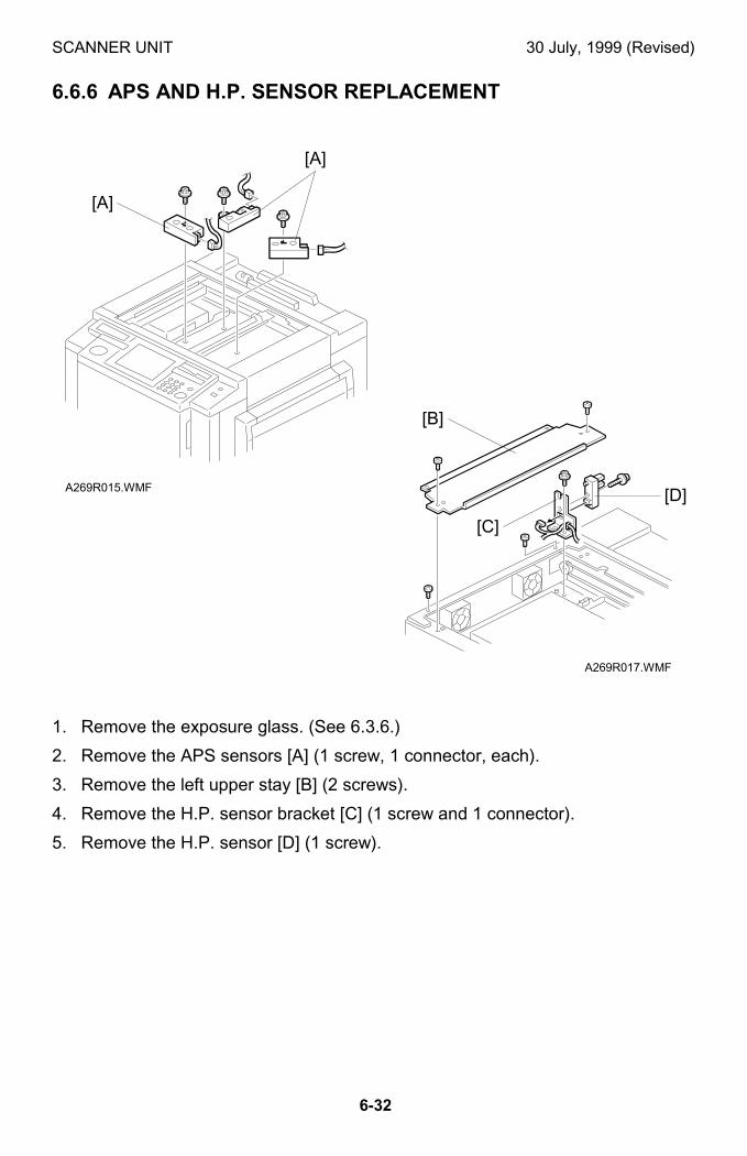
SCANNER UNIT 30 July, 1999 (Revised)
6-32
6.6.6 APS AND H.P. SENSOR REPLACEMENT
1. Remove the exposure glass. (See 6.3.6.)
2. Remove the APS sensors [A] (1 screw, 1 connector, each).
3. Remove the left upper stay [B] (2 screws).
4. Remove the H.P. sensor bracket [C] (1 screw and 1 connector).
5. Remove the H.P. sensor [D] (1 screw).
A269R015.WMF
A269R017.WMF
[A]
[A]
[B]
[C]
[D]
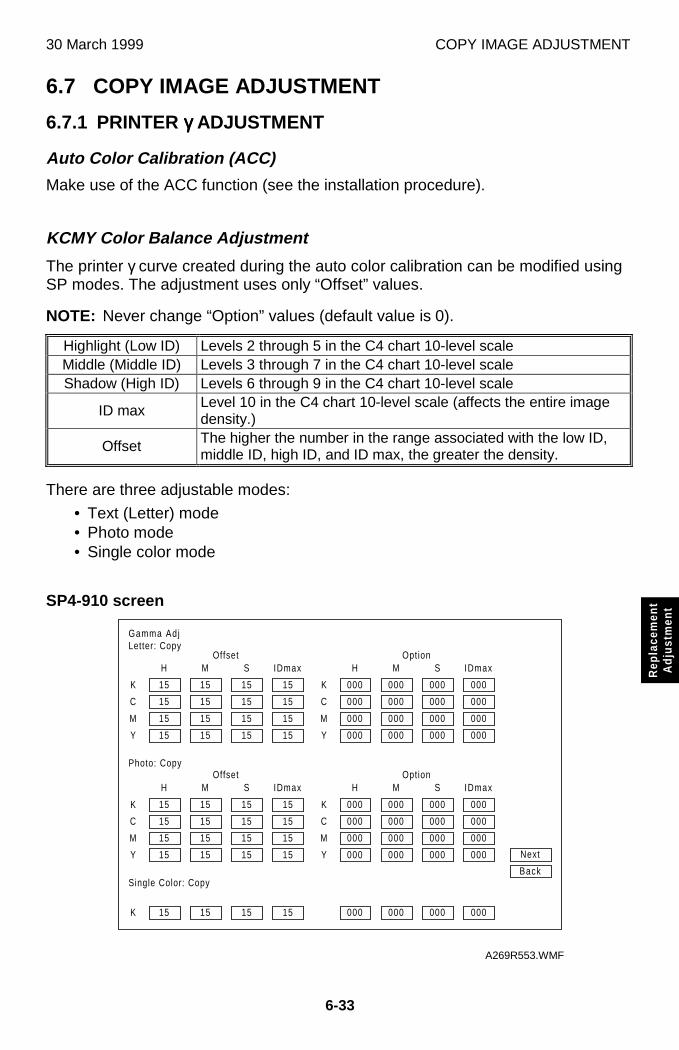
30 March 1999 COPY IMAGE ADJUSTMENT
6-33
Rep
lace
men
tA
djus
tmen
t
6.7 COPY IMAGE ADJUSTMENT
6.7.1 PRINTER γγγγ ADJUSTMENT
Auto Color Calibration (ACC)
Make use of the ACC function (see the installation procedure).
KCMY Color Balance Adjustment
The printer γ curve created during the auto color calibration can be modified usingSP modes. The adjustment uses only “Offset” values.
NOTE: Never change “Option” values (default value is 0).
Highlight (Low ID) Levels 2 through 5 in the C4 chart 10-level scaleMiddle (Middle ID) Levels 3 through 7 in the C4 chart 10-level scaleShadow (High ID) Levels 6 through 9 in the C4 chart 10-level scale
ID max Level 10 in the C4 chart 10-level scale (affects the entire imagedensity.)
Offset The higher the number in the range associated with the low ID,middle ID, high ID, and ID max, the greater the density.
There are three adjustable modes:
• Text (Letter) mode• Photo mode• Single color mode
SP4-910 screen
Gamma AdjLetter: Copy
15
15
H
C
M
Y
Single Color: Copy
K
K
15
15
15
15
15
M
15
15
15
15
15
S
15
15
15
15
15
IDmax
15
15
15
000
000
H
C
M
Y
K
000
000
000
000
000
M
000
000
000
000
000
S
000
000
000
000
000
IDmax
000
000
000
Offset Option
Next
Back
Photo: Copy
K
C
M
Y
15
15
15
15
15
15
15
15
15
15
15
15
15
15
15
15
K
C
M
Y
000
000
000
000
000
000
000
000
000
000
000
000
000
000
000
000
H M S IDmax H M S IDmaxOffset Option
A269R553.WMF

COPY IMAGE ADJUSTMENT 30 July, 1999 (Revised)
6-34
Adjustment Procedure
1. Enter the SP mode.
2. Open the 4-910 screen.
3. Adjust the offset values until the copy quality conforms to the standard.
NOTE: Never change “Option” value (default value is 0).
<Standard Copy Quality in Text Mode>
Standard Copy Quality in Text ModeStep Item to Adjust Level on the C-4 chart Adjustment Standard
1ID max:(K, C, M, and Y)
Adjust the offset value so that thedensity of level 10 matches that oflevel 10 on the C-4 chart.
2Middle (Middle ID)(K, C, M, and Y)
Adjust the offset value so that thedensity of level 6 matches that oflevel 6 on the C-4 chart.
3Shadow (High ID)(K, C, M, and Y)
Adjust the offset value so that thedensity of level 8 matches that oflevel 8 on the C-4 chart.
4
Highlight (Low ID)(K, C, M, and Y)
Adjust the offset value so thatlevel 2 is not visible on the copyand the density of level 3 matchesthat of level 3 on the C-4 chart.
4. Copy the C-4 chart in the text mode.
5. Open the 4-910 screen.
6. Adjust the offset values until the copy quality conforms to the standard.
NOTE: Never change “Option” value (default value is 0).
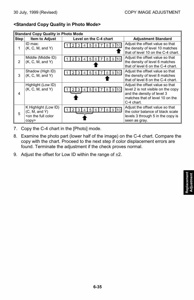
30 July, 1999 (Revised) COPY IMAGE ADJUSTMENT
6-35
Rep
lace
men
tA
dju
stm
ent
<Standard Copy Quality in Photo Mode>
Standard Copy Quality in Photo ModeStep Item to Adjust Level on the C-4 chart Adjustment Standard
1ID max:(K, C, M, and Y)
Adjust the offset value so thatthe density of level 10 matchesthat of level 10 on the C-4 chart.
2Middle (Middle ID)(K, C, M, and Y)
Adjust the offset value so thatthe density of level 6 matchesthat of level 6 on the C-4 chart.
3Shadow (High ID)(K, C, M, and Y)
Adjust the offset value so thatthe density of level 8 matchesthat of level 8 on the C-4 chart.
4
Highlight (Low ID)(K, C, M, and Y)
Adjust the offset value so thatlevel 2 is not visible on the copyand the density of level 3matches that of level 10 on theC-4 chart.
5
K Highlight (Low ID)(C, M, and Y)<on the full colorcopy>
Adjust the offset value so thatthe color balance of black scalelevels 3 through 5 in the copy isseen as gray.
7. Copy the C-4 chart in the [Photo] mode.
8. Examine the photo part (lower half of the image) on the C-4 chart. Compare thecopy with the chart. Proceed to the next step if color displacement errors arefound. Terminate the adjustment if the check proves normal.
9. Adjust the offset for Low ID within the range of ±2.
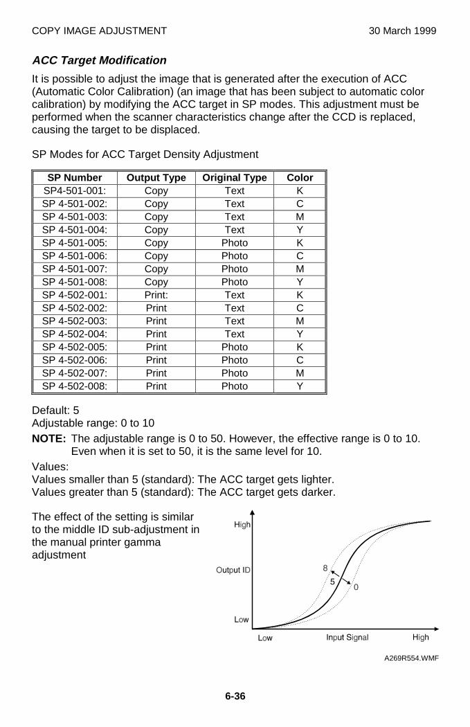
COPY IMAGE ADJUSTMENT 30 March 1999
6-36
ACC Target Modification
It is possible to adjust the image that is generated after the execution of ACC(Automatic Color Calibration) (an image that has been subject to automatic colorcalibration) by modifying the ACC target in SP modes. This adjustment must beperformed when the scanner characteristics change after the CCD is replaced,causing the target to be displaced.
SP Modes for ACC Target Density Adjustment
SP Number Output Type Original Type ColorSP4-501-001: Copy Text KSP 4-501-002: Copy Text CSP 4-501-003: Copy Text MSP 4-501-004: Copy Text YSP 4-501-005: Copy Photo KSP 4-501-006: Copy Photo CSP 4-501-007: Copy Photo MSP 4-501-008: Copy Photo YSP 4-502-001: Print: Text KSP 4-502-002: Print Text CSP 4-502-003: Print Text MSP 4-502-004: Print Text YSP 4-502-005: Print Photo KSP 4-502-006: Print Photo CSP 4-502-007: Print Photo MSP 4-502-008: Print Photo Y
Default: 5Adjustable range: 0 to 10NOTE: The adjustable range is 0 to 50. However, the effective range is 0 to 10.
Even when it is set to 50, it is the same level for 10.Values:Values smaller than 5 (standard): The ACC target gets lighter.Values greater than 5 (standard): The ACC target gets darker.
The effect of the setting is similarto the middle ID sub-adjustment inthe manual printer gammaadjustment
A269R554.WMF
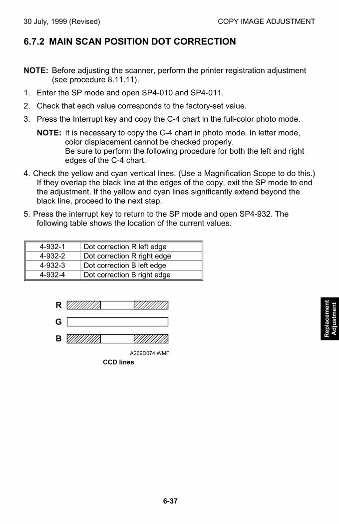
30 July, 1999 (Revised) COPY IMAGE ADJUSTMENT
6-37
Rep
lace
men
tA
dju
stm
ent
6.7.2 MAIN SCAN POSITION DOT CORRECTION
NOTE: Before adjusting the scanner, perform the printer registration adjustment(see procedure 8.11.11).
1. Enter the SP mode and open SP4-010 and SP4-011.
2. Check that each value corresponds to the factory-set value.
3. Press the Interrupt key and copy the C-4 chart in the full-color photo mode.
NOTE: It is necessary to copy the C-4 chart in photo mode. In letter mode,color displacement cannot be checked properly.Be sure to perform the following procedure for both the left and rightedges of the C-4 chart.
4. Check the yellow and cyan vertical lines. (Use a Magnification Scope to do this.)If they overlap the black line at the edges of the copy, exit the SP mode to endthe adjustment. If the yellow and cyan lines significantly extend beyond theblack line, proceed to the next step.
5. Press the interrupt key to return to the SP mode and open SP4-932. Thefollowing table shows the location of the current values.
4-932-1 Dot correction R left edge4-932-2 Dot correction R right edge4-932-3 Dot correction B left edge4-932-4 Dot correction B right edge
���� ����
��������
��������
R
G
B
A269D074.WMF
CCD lines
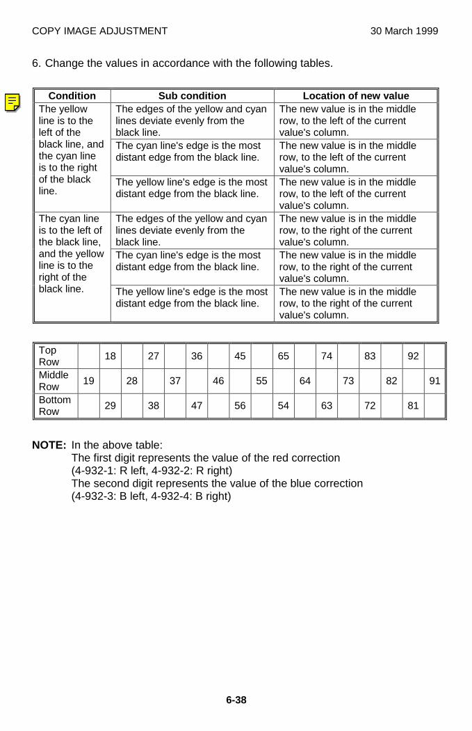
COPY IMAGE ADJUSTMENT 30 March 1999
6-38
6. Change the values in accordance with the following tables.
Condition Sub condition Location of new valueThe edges of the yellow and cyanlines deviate evenly from theblack line.
The new value is in the middlerow, to the left of the currentvalue's column.
The cyan line's edge is the mostdistant edge from the black line.
The new value is in the middlerow, to the left of the currentvalue's column.
The yellowline is to theleft of theblack line, andthe cyan lineis to the rightof the blackline.
The yellow line's edge is the mostdistant edge from the black line.
The new value is in the middlerow, to the left of the currentvalue's column.
The edges of the yellow and cyanlines deviate evenly from theblack line.
The new value is in the middlerow, to the right of the currentvalue's column.
The cyan line's edge is the mostdistant edge from the black line.
The new value is in the middlerow, to the right of the currentvalue's column.
The cyan lineis to the left ofthe black line,and the yellowline is to theright of theblack line. The yellow line's edge is the most
distant edge from the black line.The new value is in the middlerow, to the right of the currentvalue's column.
TopRow 18 27 36 45 65 74 83 92
MiddleRow 19 28 37 46 55 64 73 82 91
BottomRow 29 38 47 56 54 63 72 81
NOTE: In the above table:The first digit represents the value of the red correction(4-932-1: R left, 4-932-2: R right)The second digit represents the value of the blue correction(4-932-3: B left, 4-932-4: B right)
30 March 1999 COPY IMAGE ADJUSTMENT
6-39
Rep
lace
men
tA
djus
tmen
t
Example:
1. The C-4 chart's vertical lines do not overlap properly. On the right side of thechart, the yellow line is to the left of the black line and the cyan line is to theright of the black line. The yellow line's edge is the most distant edge from theblack line. These conditions are used to determine what the new values shouldbe. The new value is located in the bottom row, to the left of the current value'scolumn. For the right side of the chart, the machine's current red correctionvalue is 6 (4-932-2), and the blue correction value is 5 (4-932-4). Therefore, thecurrent value in the chart is 65. The new value (bottom row to the left) is 56.
2. On the left side of the chart, the cyan line is to the left of the black line and theyellow line is to the right of the black line. The edges of the yellow and cyanlines deviate evenly from the black line. These conditions are used todetermine what the new values should be. The new value is located in themiddle row, to the right of the current value's column. For the left side of thechart, the machine's current red correction value is 6 (4-932-1), and the bluecorrection value is 4 (4-932-3). Therefore, the current value in the chart is 64.The new value (middle row to the right) is 73.
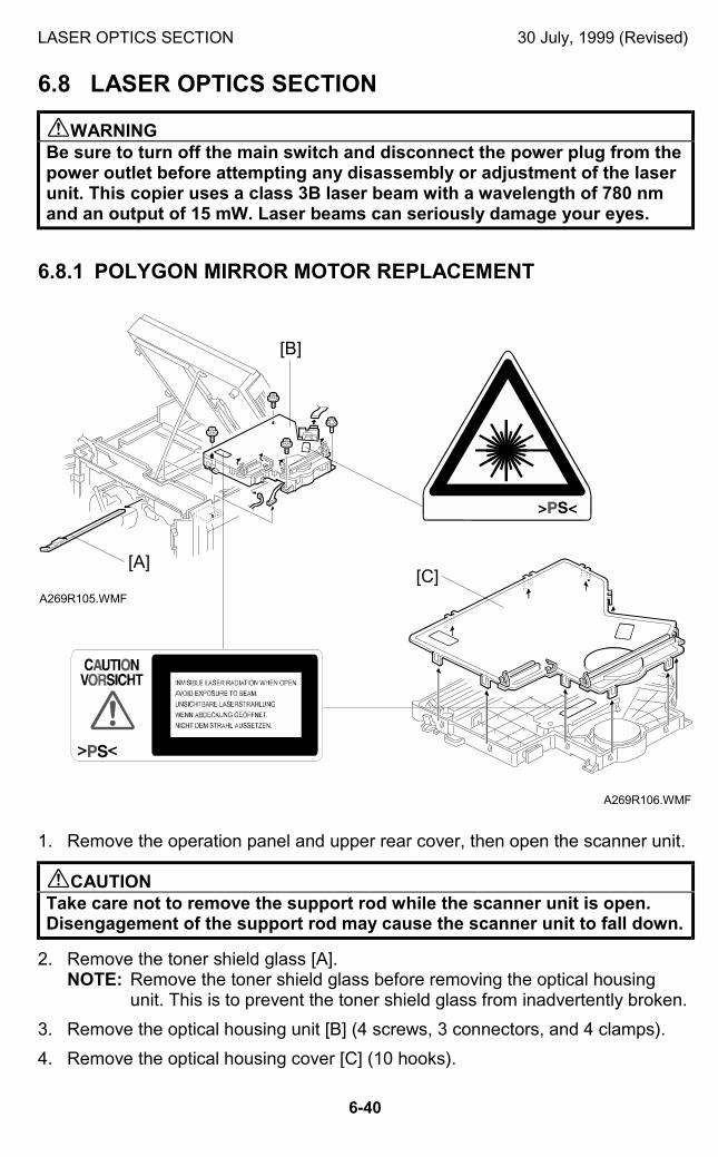
LASER OPTICS SECTION 30 July, 1999 (Revised)
6-40
6.8 LASER OPTICS SECTION
!WARNINGBe sure to turn off the main switch and disconnect the power plug from thepower outlet before attempting any disassembly or adjustment of the laserunit. This copier uses a class 3B laser beam with a wavelength of 780 nmand an output of 15 mW. Laser beams can seriously damage your eyes.
6.8.1 POLYGON MIRROR MOTOR REPLACEMENT
1. Remove the operation panel and upper rear cover, then open the scanner unit.
!CAUTIONTake care not to remove the support rod while the scanner unit is open.Disengagement of the support rod may cause the scanner unit to fall down.
2. Remove the toner shield glass [A].NOTE: Remove the toner shield glass before removing the optical housing
unit. This is to prevent the toner shield glass from inadvertently broken.
3. Remove the optical housing unit [B] (4 screws, 3 connectors, and 4 clamps).
4. Remove the optical housing cover [C] (10 hooks).
A269R106.WMF
A269R105.WMF
[A]
[B]
[C]
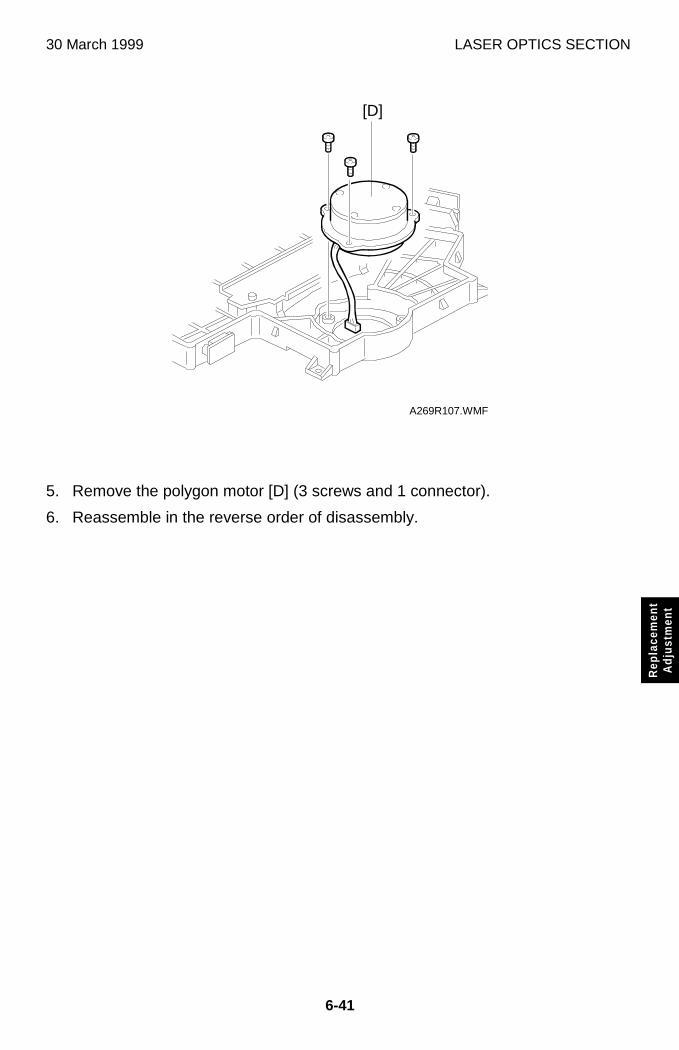
30 March 1999 LASER OPTICS SECTION
6-41
Rep
lace
men
tA
djus
tmen
t
5. Remove the polygon motor [D] (3 screws and 1 connector).
6. Reassemble in the reverse order of disassembly.
A269R107.WMF
[D]
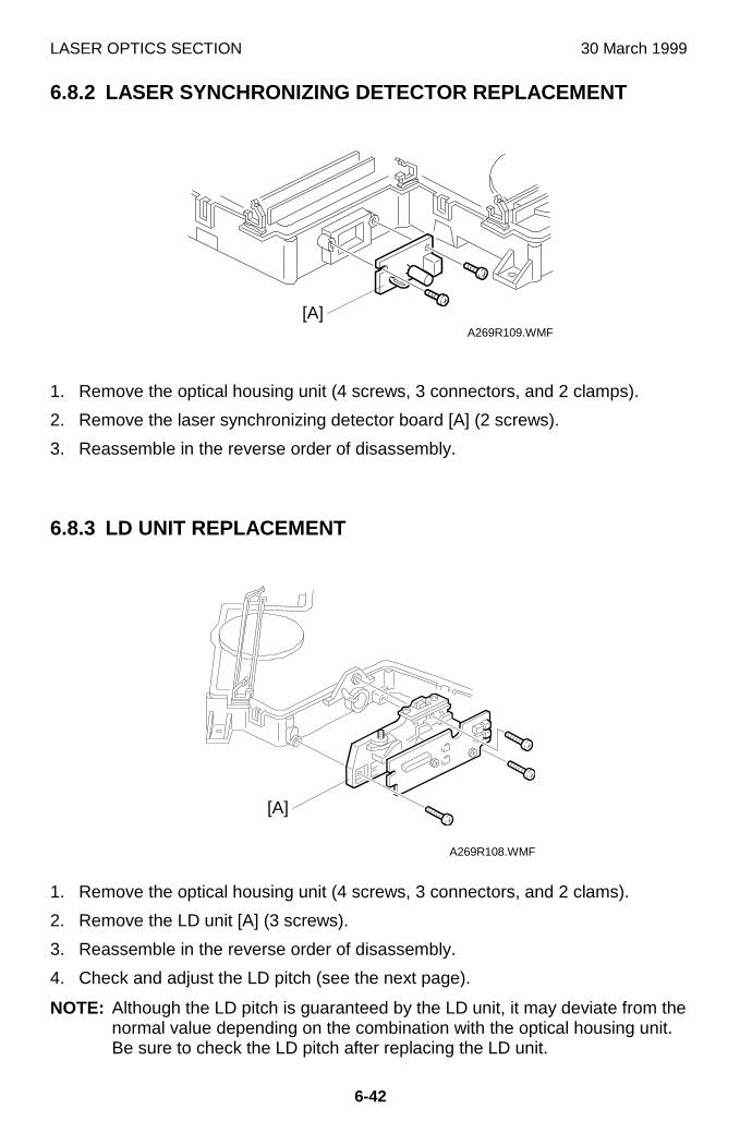
LASER OPTICS SECTION 30 March 1999
6-42
6.8.2 LASER SYNCHRONIZING DETECTOR REPLACEMENT
1. Remove the optical housing unit (4 screws, 3 connectors, and 2 clamps).
2. Remove the laser synchronizing detector board [A] (2 screws).
3. Reassemble in the reverse order of disassembly.
6.8.3 LD UNIT REPLACEMENT
1. Remove the optical housing unit (4 screws, 3 connectors, and 2 clams).
2. Remove the LD unit [A] (3 screws).
3. Reassemble in the reverse order of disassembly.
4. Check and adjust the LD pitch (see the next page).
NOTE: Although the LD pitch is guaranteed by the LD unit, it may deviate from thenormal value depending on the combination with the optical housing unit.Be sure to check the LD pitch after replacing the LD unit.
A269R109.WMF
A269R108.WMF
[A]
[A]
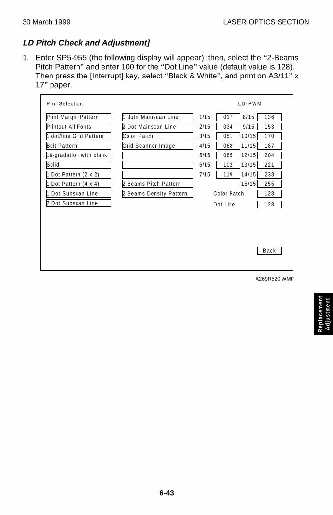
30 March 1999 LASER OPTICS SECTION
6-43
Rep
lace
men
tA
djus
tmen
t
LD Pitch Check and Adjustment]
1. Enter SP5-955 (the following display will appear); then, select the “2-BeamsPitch Pattern” and enter 100 for the “Dot Line” value (default value is 128).Then press the [Interrupt] key, select “Black & White” , and print on A3/11” x17” paper.
Ptrn Select ion
017
034
051
068
085
102
119
Back
Print Margin Pattern
2 Dot Subscan L ine
Printout Al l Fonts
1 dot/ l ine Grid Pattern
Belt Pattern
16-gradat ion with blank
Sol id
1 Dot Pattern (2 x 2)
1 Dot Pattern (4 x 4)
1 Dot Subscan L ine
1 dotn Mainscan Line
2 Dot Mainscan Line
Color Patch
Gr id Scanner Image
2 Beams Pi tch Pattern
2 Beams Densi ty Pat tern
136
153
170
187
204
221
238
1/15
2/15
3/15
4/15
5/15
6/15
7/15
8/15
9/15
10/15
11/15
12/15
13/15
14/15
255
128
128
15/15
Color Patch
Dot Line
L D - P W M
A269R520.WMF
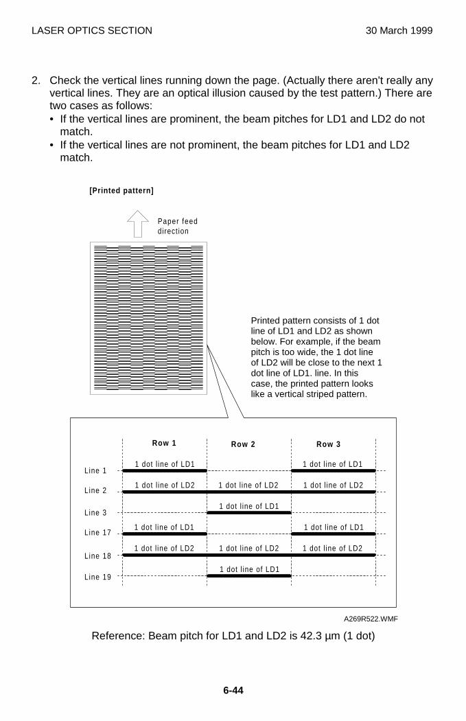
LASER OPTICS SECTION 30 March 1999
6-44
2. Check the vertical lines running down the page. (Actually there aren't really anyvertical lines. They are an optical illusion caused by the test pattern.) There aretwo cases as follows:• If the vertical lines are prominent, the beam pitches for LD1 and LD2 do not
match.• If the vertical lines are not prominent, the beam pitches for LD1 and LD2
match.
Reference: Beam pitch for LD1 and LD2 is 42.3 µm (1 dot)
��������������������������������������������������������������������������������������������������������1 dot l ine of LD1
��������������������������������������������������������������������������������������������������
1 dot l ine of LD2
1 dot l ine of LD1
1 dot l ine of LD2 1 dot l ine of LD2 1 dot l ine of LD2
1 dot l ine of LD1
1 dot l ine of LD2
1 dot l ine of LD1
1 dot l ine of LD2
1 dot l ine of LD1
1 dot l ine of LD1
Row 1 Row 2 Row 3
Line 1
Line 2
Line 3
Line 17
Line 18
Line 19
����������������������������������������������������������������������������������������������������������������������������������������������������������������������������������������������������������������������������������������������������������������������������������������������������������
��������������������������������������������������������������������������������������������������
��������������������������������������������������������������������������������������������������������
��������������������������������������������������������������������������������������������������
����������������������������������������������������������������������������������������������������������������������������������������������������������������������������������������������������������������������������������������������������������������������������������������������������������
��������������������������������������������������������������������������������������������������
Paper feeddirect ion
[Printed pattern]
A269R522.WMF
Printed pattern consists of 1 dotline of LD1 and LD2 as shownbelow. For example, if the beampitch is too wide, the 1 dot lineof LD2 will be close to the next 1dot line of LD1. line. In thiscase, the printed pattern lookslike a vertical striped pattern.
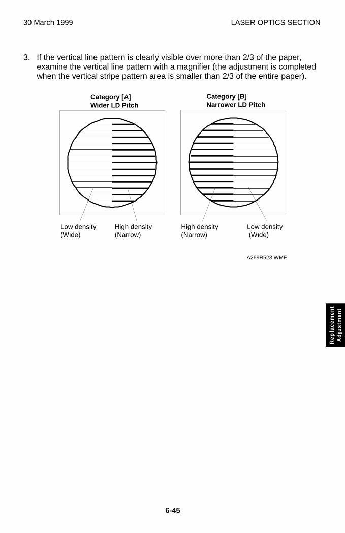
30 March 1999 LASER OPTICS SECTION
6-45
Rep
lace
men
tA
djus
tmen
t
3. If the vertical line pattern is clearly visible over more than 2/3 of the paper,examine the vertical line pattern with a magnifier (the adjustment is completedwhen the vertical stripe pattern area is smaller than 2/3 of the entire paper).
A269R523.WMF
Category [A]Wider LD Pitch
Category [B]Narrower LD Pitch
Low density(Wide)
High density(Narrow)
High density(Narrow)
Low density (Wide)
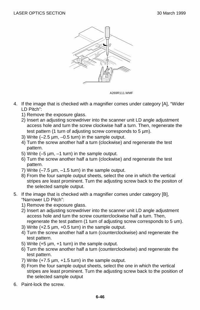
LASER OPTICS SECTION 30 March 1999
6-46
4. If the image that is checked with a magnifier comes under category [A], “WiderLD Pitch”:1) Remove the exposure glass.2) Insert an adjusting screwdriver into the scanner unit LD angle adjustment
access hole and turn the screw clockwise half a turn. Then, regenerate thetest pattern (1 turn of adjusting screw corresponds to 5 µm).
3) Write (–2.5 µm, –0.5 turn) in the sample output.4) Turn the screw another half a turn (clockwise) and regenerate the test
pattern.5) Write (–5 µm, –1 turn) in the sample output.6) Turn the screw another half a turn (clockwise) and regenerate the test
pattern.7) Write (–7.5 µm, –1.5 turn) in the sample output.8) From the four sample output sheets, select the one in which the vertical
stripes are least prominent. Turn the adjusting screw back to the positon ofthe selected sample output.
5. If the image that is checked with a magnifier comes under category [B],“Narrower LD Pitch”:1) Remove the exposure glass.2) Insert an adjusting screwdriver into the scanner unit LD angle adjustment
access hole and turn the screw counterclockwise half a turn. Then,regenerate the test pattern (1 turn of adjusting screw corresponds to 5 um).
3) Write (+2.5 µm, +0.5 turn) in the sample output.4) Turn the screw another half a turn (counterclockwise) and regenerate the
test pattern.5) Write (+5 µm, +1 turn) in the sample output.6) Turn the screw another half a turn (counterclockwise) and regenerate the
test pattern.7) Write (+7.5 µm, +1.5 turn) in the sample output.8) From the four sample output sheets, select the one in which the vertical
stripes are least prominent. Turn the adjusting screw back to the position ofthe selected sample output
6. Paint-lock the screw.
A269R111.WMF
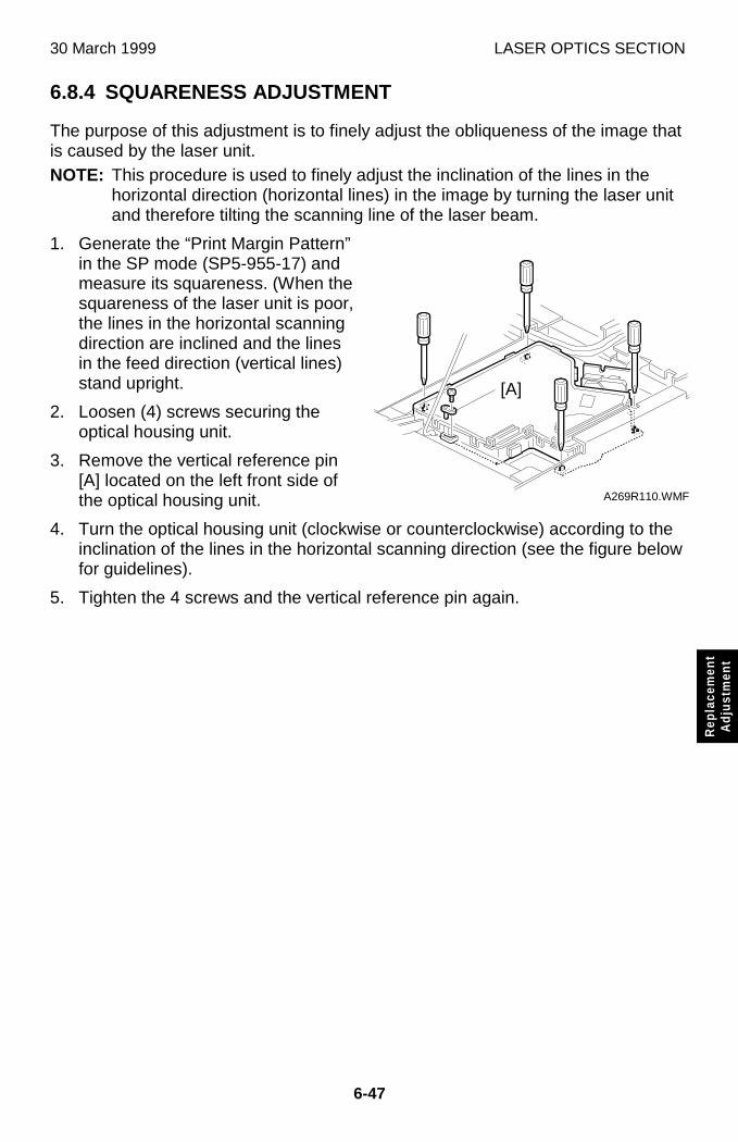
30 March 1999 LASER OPTICS SECTION
6-47
Rep
lace
men
tA
djus
tmen
t
6.8.4 SQUARENESS ADJUSTMENT
The purpose of this adjustment is to finely adjust the obliqueness of the image thatis caused by the laser unit.NOTE: This procedure is used to finely adjust the inclination of the lines in the
horizontal direction (horizontal lines) in the image by turning the laser unitand therefore tilting the scanning line of the laser beam.
1. Generate the “Print Margin Pattern”in the SP mode (SP5-955-17) andmeasure its squareness. (When thesquareness of the laser unit is poor,the lines in the horizontal scanningdirection are inclined and the linesin the feed direction (vertical lines)stand upright.
2. Loosen (4) screws securing theoptical housing unit.
3. Remove the vertical reference pin[A] located on the left front side ofthe optical housing unit.
4. Turn the optical housing unit (clockwise or counterclockwise) according to theinclination of the lines in the horizontal scanning direction (see the figure belowfor guidelines).
5. Tighten the 4 screws and the vertical reference pin again.
A269R110.WMF
[A]
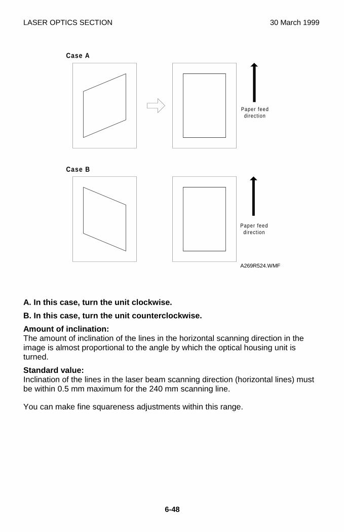
LASER OPTICS SECTION 30 March 1999
6-48
A. In this case, turn the unit clockwise.
B. In this case, turn the unit counterclockwise.
Amount of inclination:The amount of inclination of the lines in the horizontal scanning direction in theimage is almost proportional to the angle by which the optical housing unit isturned.
Standard value:Inclination of the lines in the laser beam scanning direction (horizontal lines) mustbe within 0.5 mm maximum for the 240 mm scanning line.
You can make fine squareness adjustments within this range.
Case A
Case B
Paper feeddirect ion
Paper feeddirect ion
A269R524.WMF
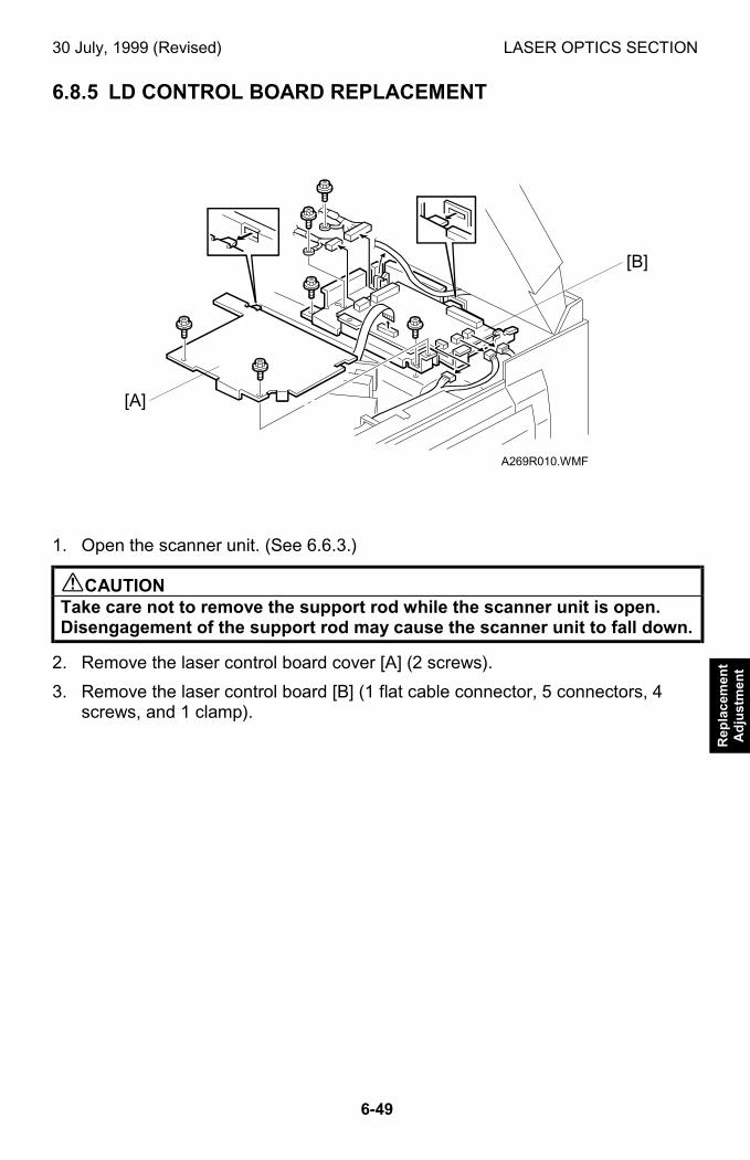
30 July, 1999 (Revised) LASER OPTICS SECTION
6-49
Rep
lace
men
tA
dju
stm
ent
6.8.5 LD CONTROL BOARD REPLACEMENT
1. Open the scanner unit. (See 6.6.3.)
!CAUTIONTake care not to remove the support rod while the scanner unit is open.Disengagement of the support rod may cause the scanner unit to fall down.
2. Remove the laser control board cover [A] (2 screws).
3. Remove the laser control board [B] (1 flat cable connector, 5 connectors, 4screws, and 1 clamp).
A269R010.WMF
[A]
[B]
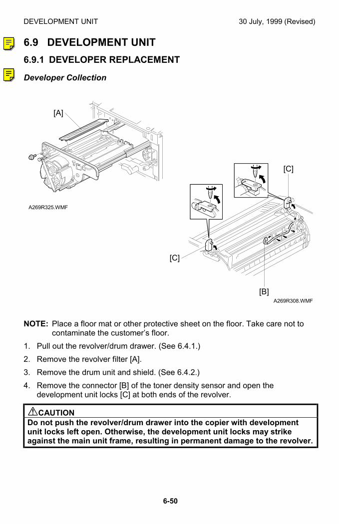
DEVELOPMENT UNIT 30 July, 1999 (Revised)
6-50
6.9 DEVELOPMENT UNIT
6.9.1 DEVELOPER REPLACEMENT
Developer Collection
NOTE: Place a floor mat or other protective sheet on the floor. Take care not tocontaminate the customer’s floor.
1. Pull out the revolver/drum drawer. (See 6.4.1.)
2. Remove the revolver filter [A].
3. Remove the drum unit and shield. (See 6.4.2.)
4. Remove the connector [B] of the toner density sensor and open thedevelopment unit locks [C] at both ends of the revolver.
!CAUTIONDo not push the revolver/drum drawer into the copier with developmentunit locks left open. Otherwise, the development unit locks may strikeagainst the main unit frame, resulting in permanent damage to the revolver.
A269R325.WMF
A269R308.WMF
[A]
[C]
[C]
[B]
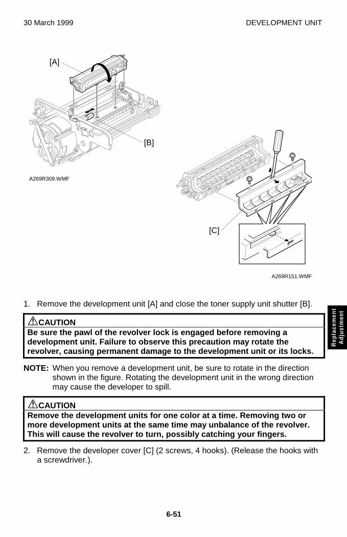
30 March 1999 DEVELOPMENT UNIT
6-51
Rep
lace
men
tA
djus
tmen
t
1. Remove the development unit [A] and close the toner supply unit shutter [B].
øCAUTIONBe sure the pawl of the revolver lock is engaged before removing adevelopment unit. Failure to observe this precaution may rotate therevolver, causing permanent damage to the development unit or its locks.
NOTE: When you remove a development unit, be sure to rotate in the directionshown in the figure. Rotating the development unit in the wrong directionmay cause the developer to spill.
øCAUTIONRemove the development units for one color at a time. Removing two ormore development units at the same time may unbalance of the revolver.This will cause the revolver to turn, possibly catching your fingers.
2. Remove the developer cover [C] (2 screws, 4 hooks). (Release the hooks witha screwdriver.).
A269R309.WMF
A269R151.WMF
[A]
[B]
[C]
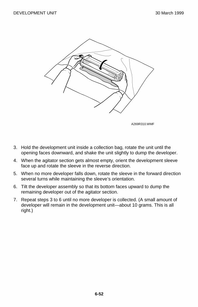
DEVELOPMENT UNIT 30 March 1999
6-52
3. Hold the development unit inside a collection bag, rotate the unit until theopening faces downward, and shake the unit slightly to dump the developer.
4. When the agitator section gets almost empty, orient the development sleeveface up and rotate the sleeve in the reverse direction.
5. When no more developer falls down, rotate the sleeve in the forward directionseveral turns while maintaining the sleeve’s orientation.
6. Tilt the developer assembly so that its bottom faces upward to dump theremaining developer out of the agitator section.
7. Repeat steps 3 to 6 until no more developer is collected. (A small amount ofdeveloper will remain in the development unit—about 10 grams. This is allright.)
A269R310.WMF
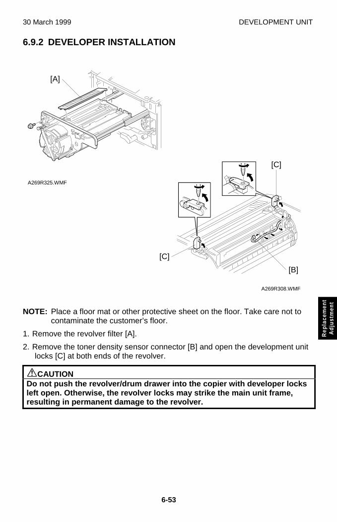
30 March 1999 DEVELOPMENT UNIT
6-53
Rep
lace
men
tA
djus
tmen
t
6.9.2 DEVELOPER INSTALLATION
NOTE: Place a floor mat or other protective sheet on the floor. Take care not tocontaminate the customer’s floor.
1. Remove the revolver filter [A].
2. Remove the toner density sensor connector [B] and open the development unitlocks [C] at both ends of the revolver.
øCAUTIONDo not push the revolver/drum drawer into the copier with developer locksleft open. Otherwise, the revolver locks may strike the main unit frame,resulting in permanent damage to the revolver.
A269R308.WMF
A269R325.WMF
[C]
[C]
[B]
[A]
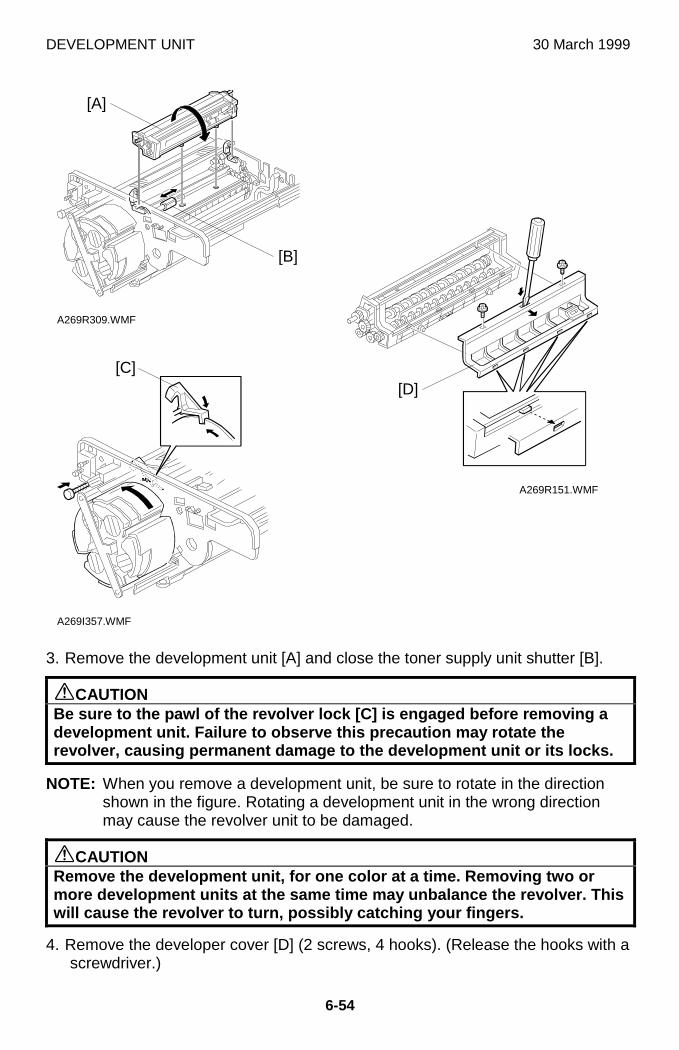
DEVELOPMENT UNIT 30 March 1999
6-54
3. Remove the development unit [A] and close the toner supply unit shutter [B].
øCAUTIONBe sure to the pawl of the revolver lock [C] is engaged before removing adevelopment unit. Failure to observe this precaution may rotate therevolver, causing permanent damage to the development unit or its locks.
NOTE: When you remove a development unit, be sure to rotate in the directionshown in the figure. Rotating a development unit in the wrong directionmay cause the revolver unit to be damaged.
øCAUTIONRemove the development unit, for one color at a time. Removing two ormore development units at the same time may unbalance the revolver. Thiswill cause the revolver to turn, possibly catching your fingers.
4. Remove the developer cover [D] (2 screws, 4 hooks). (Release the hooks with ascrewdriver.)
A269R309.WMF
A269R151.WMF
A269I357.WMF
[A]
[D]
[B]
[C]
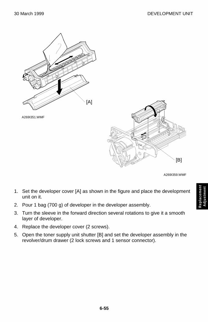
30 March 1999 DEVELOPMENT UNIT
6-55
Rep
lace
men
tA
djus
tmen
t
1. Set the developer cover [A] as shown in the figure and place the developmentunit on it.
2. Pour 1 bag (700 g) of developer in the developer assembly.
3. Turn the sleeve in the forward direction several rotations to give it a smoothlayer of developer.
4. Replace the developer cover (2 screws).
5. Open the toner supply unit shutter [B] and set the developer assembly in therevolver/drum drawer (2 lock screws and 1 sensor connector).
A269I351.WMF
A269I359.WMF
[A]
[B]
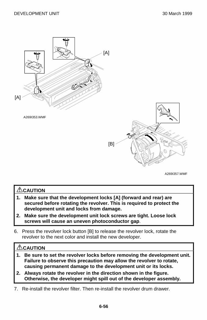
DEVELOPMENT UNIT 30 March 1999
6-56
øCAUTION1. Make sure that the development locks [A] (forward and rear) are
secured before rotating the revolver. This is required to protect thedevelopment unit and locks from damage.
2. Make sure the development unit lock screws are tight. Loose lockscrews will cause an uneven photoconductor gap .
6. Press the revolver lock button [B] to release the revolver lock, rotate therevolver to the next color and install the new developer.
øCAUTION1. Be sure to set the revolver locks before removing the development unit.
Failure to observe this precaution may allow the revolver to rotate,causing permanent damage to the development unit or its locks.
2. Always rotate the revolver in the direction shown in the figure.Otherwise, the developer might spill out of the developer assembly.
7. Re-install the revolver filter. Then re-install the revolver drum drawer.
A269I353.WMF
A269I357.WMF
[A]
[B]
[A]
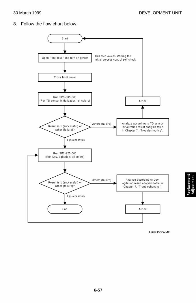
30 March 1999 DEVELOPMENT UNIT
6-57
Rep
lace
men
tA
djus
tmen
t
8. Follow the flow chart below.
1 (successful)
Start
Result is 1 (successful) orOther (fai lure)?
Open front cover and turn on power
Close front cover
Run SP3-005-005(Run TD sensor init ial ization: al l colors)
Run SP2-225-005(Run Dev. agitat ion: al l colors)
Result is 1 (successful) orOther (fai lure)?
End
Analyze according to TD sensorinit ial ization result analysis tablein Chapter 7, "Troubleshooting".
Act ion
Analyze according to Dev.agitat ion result analysis table inChapter 7, "Troubleshoot ing".
Act ion
Others (fai lure)
1 (successful)
Others (fai lure)
This step avoids start ing theinit ial process control self check.
A269I153.WMF
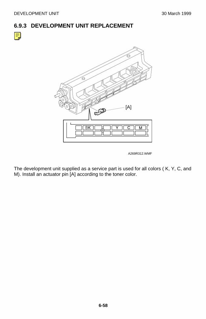
DEVELOPMENT UNIT 30 March 1999
6-58
6.9.3 DEVELOPMENT UNIT REPLACEMENT
The development unit supplied as a service part is used for all colors ( K, Y, C, andM). Install an actuator pin [A] according to the toner color.
A269R312.WMF
[A]
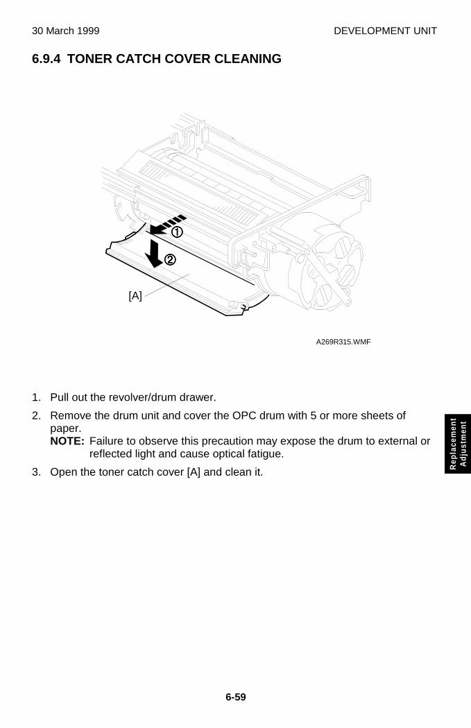
30 March 1999 DEVELOPMENT UNIT
6-59
Rep
lace
men
tA
djus
tmen
t
6.9.4 TONER CATCH COVER CLEANING
1. Pull out the revolver/drum drawer.
2. Remove the drum unit and cover the OPC drum with 5 or more sheets ofpaper.NOTE: Failure to observe this precaution may expose the drum to external or
reflected light and cause optical fatigue.
3. Open the toner catch cover [A] and clean it.
A269R315.WMF
[A]
����
����
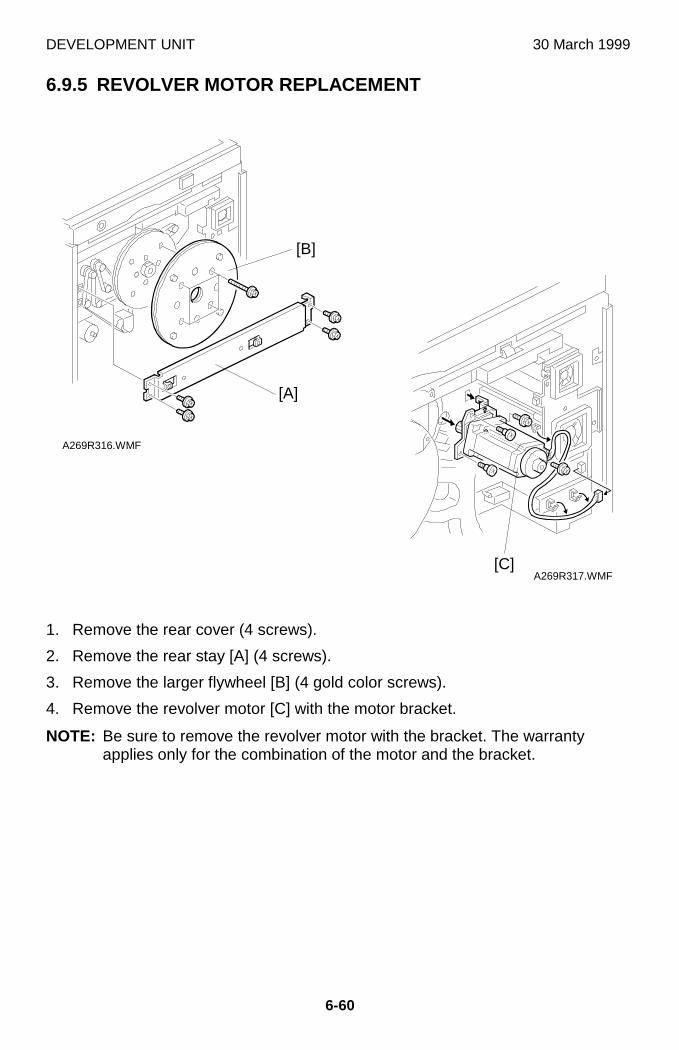
DEVELOPMENT UNIT 30 March 1999
6-60
6.9.5 REVOLVER MOTOR REPLACEMENT
1. Remove the rear cover (4 screws).
2. Remove the rear stay [A] (4 screws).
3. Remove the larger flywheel [B] (4 gold color screws).
4. Remove the revolver motor [C] with the motor bracket.
NOTE: Be sure to remove the revolver motor with the bracket. The warrantyapplies only for the combination of the motor and the bracket.
A269R316.WMF
A269R317.WMF
[A]
[B]
[C]
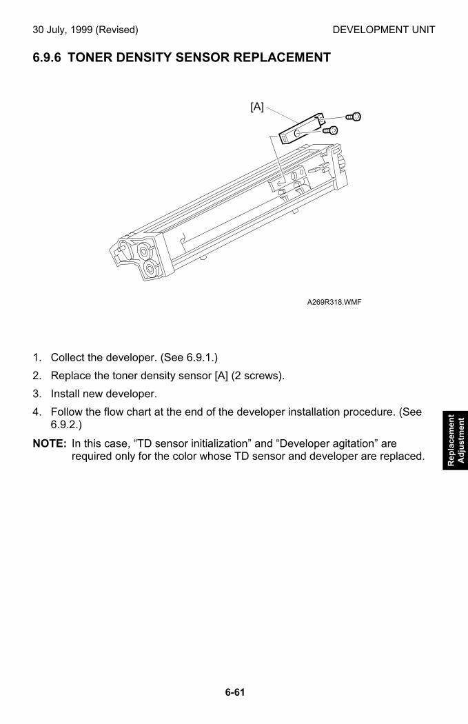
30 July, 1999 (Revised) DEVELOPMENT UNIT
6-61
Rep
lace
men
tA
dju
stm
ent
6.9.6 TONER DENSITY SENSOR REPLACEMENT
1. Collect the developer. (See 6.9.1.)
2. Replace the toner density sensor [A] (2 screws).
3. Install new developer.
4. Follow the flow chart at the end of the developer installation procedure. (See6.9.2.)
NOTE: In this case, “TD sensor initialization” and “Developer agitation” arerequired only for the color whose TD sensor and developer are replaced.
A269R318.WMF
[A]
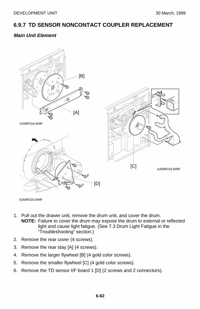
DEVELOPMENT UNIT 30 March, 1999
6-62
6.9.7 TD SENSOR NONCONTACT COUPLER REPLACEMENT
Main Unit Element
1. Pull out the drawer unit, remove the drum unit, and cover the drum.NOTE: Failure to cover the drum may expose the drum to external or reflected
light and cause light fatigue. (See 7.3 Drum Light Fatigue in the“Troubleshooting” section.)
2. Remove the rear cover (4 screws).
3. Remove the rear stay [A] (4 screws).
4. Remove the larger flywheel [B] (4 gold color screws).
5. Remove the smaller flywheel [C] (4 gold color screws).
6. Remove the TD sensor I/F board 1 [D] (2 screws and 2 connectors).
A269R316.WMF
A269R319.WMF
A269R320.WMF
[A]
[C]
[D]
[B]
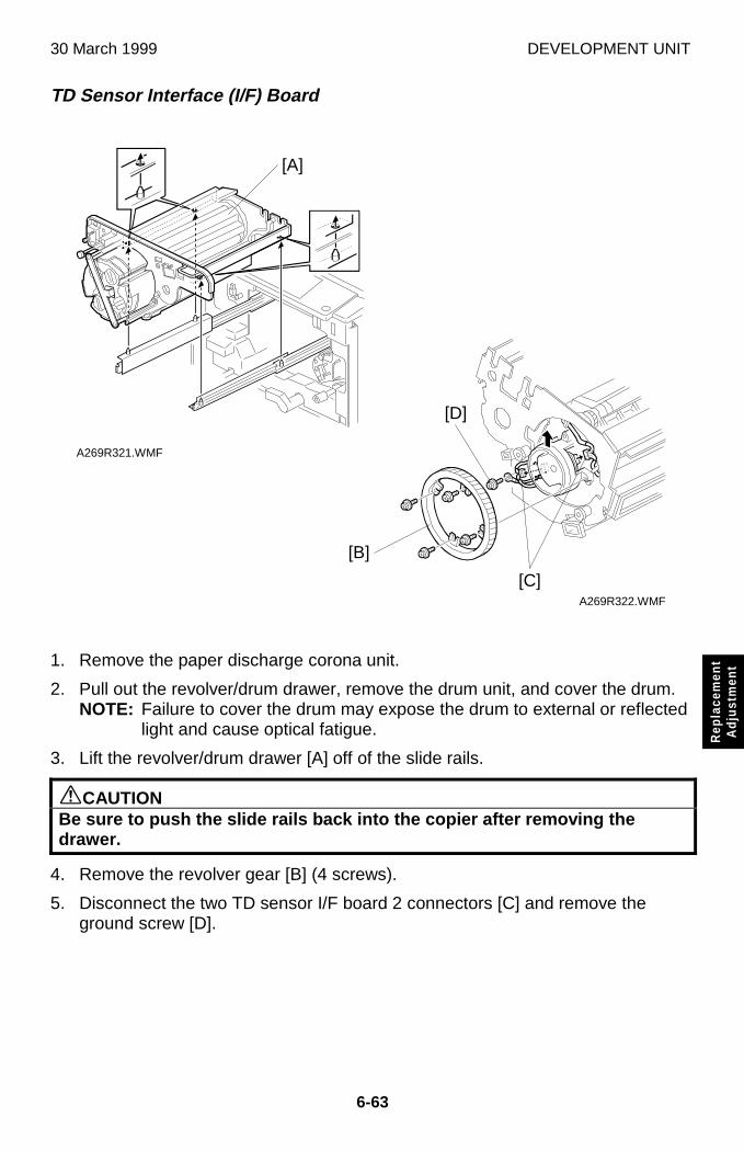
30 March 1999 DEVELOPMENT UNIT
6-63
Rep
lace
men
tA
djus
tmen
t
TD Sensor Interface (I/F) Board
1. Remove the paper discharge corona unit.
2. Pull out the revolver/drum drawer, remove the drum unit, and cover the drum.NOTE: Failure to cover the drum may expose the drum to external or reflected
light and cause optical fatigue.
3. Lift the revolver/drum drawer [A] off of the slide rails.
øCAUTIONBe sure to push the slide rails back into the copier after removing thedrawer.
4. Remove the revolver gear [B] (4 screws).
5. Disconnect the two TD sensor I/F board 2 connectors [C] and remove theground screw [D].
A269R321.WMF
A269R322.WMF
[A]
[B]
[D]
[C]
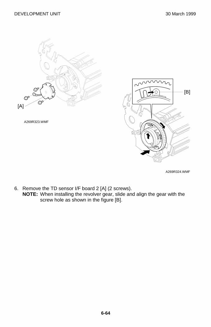
DEVELOPMENT UNIT 30 March 1999
6-64
6. Remove the TD sensor I/F board 2 [A] (2 screws).NOTE: When installing the revolver gear, slide and align the gear with the
screw hole as shown in the figure [B].
A269R323.WMF
A269R324.WMF
[A]
[B]
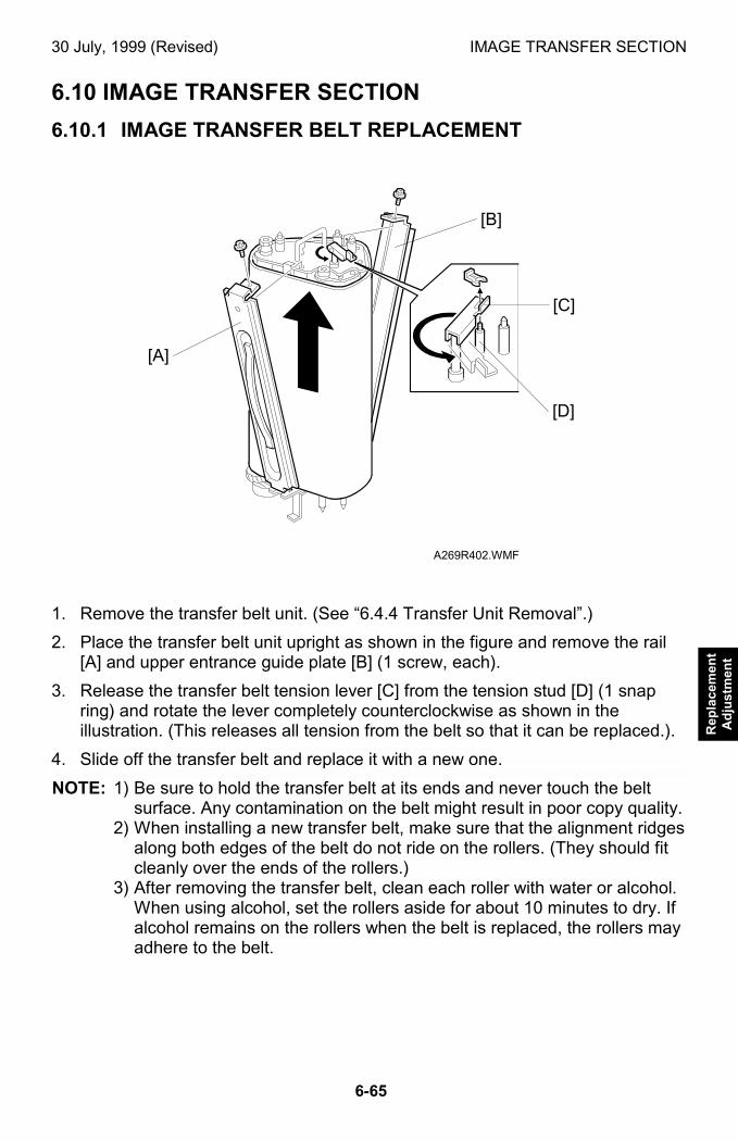
30 July, 1999 (Revised) IMAGE TRANSFER SECTION
6-65
Rep
lace
men
tA
dju
stm
ent
6.10 IMAGE TRANSFER SECTION
6.10.1 IMAGE TRANSFER BELT REPLACEMENT
1. Remove the transfer belt unit. (See “6.4.4 Transfer Unit Removal”.)
2. Place the transfer belt unit upright as shown in the figure and remove the rail[A] and upper entrance guide plate [B] (1 screw, each).
3. Release the transfer belt tension lever [C] from the tension stud [D] (1 snapring) and rotate the lever completely counterclockwise as shown in theillustration. (This releases all tension from the belt so that it can be replaced.).
4. Slide off the transfer belt and replace it with a new one.
NOTE: 1) Be sure to hold the transfer belt at its ends and never touch the beltsurface. Any contamination on the belt might result in poor copy quality.
2) When installing a new transfer belt, make sure that the alignment ridgesalong both edges of the belt do not ride on the rollers. (They should fitcleanly over the ends of the rollers.)
3) After removing the transfer belt, clean each roller with water or alcohol.When using alcohol, set the rollers aside for about 10 minutes to dry. Ifalcohol remains on the rollers when the belt is replaced, the rollers mayadhere to the belt.
A269R402.WMF
[A]
[B]
[C]
[D]
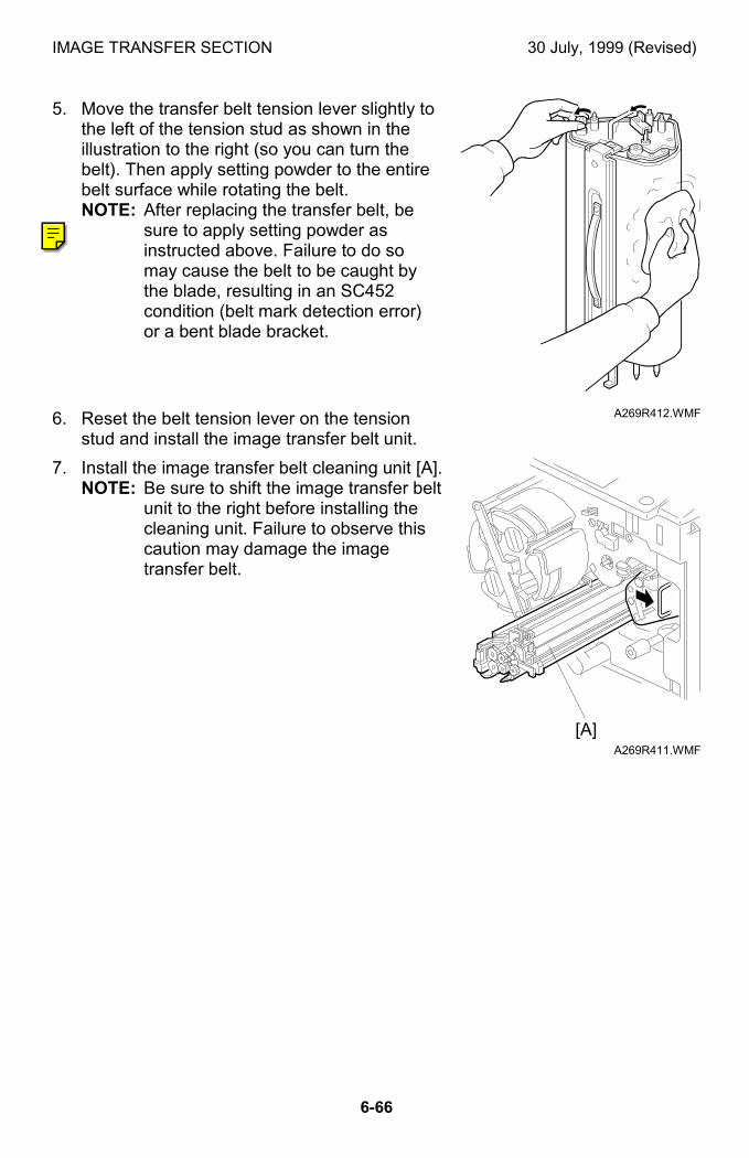
IMAGE TRANSFER SECTION 30 July, 1999 (Revised)
6-66
5. Move the transfer belt tension lever slightly tothe left of the tension stud as shown in theillustration to the right (so you can turn thebelt). Then apply setting powder to the entirebelt surface while rotating the belt.NOTE: After replacing the transfer belt, be
sure to apply setting powder asinstructed above. Failure to do somay cause the belt to be caught bythe blade, resulting in an SC452condition (belt mark detection error)or a bent blade bracket.
6. Reset the belt tension lever on the tensionstud and install the image transfer belt unit.
7. Install the image transfer belt cleaning unit [A].NOTE: Be sure to shift the image transfer belt
unit to the right before installing thecleaning unit. Failure to observe thiscaution may damage the imagetransfer belt.
A269R412.WMF
A269R411.WMF
[A]
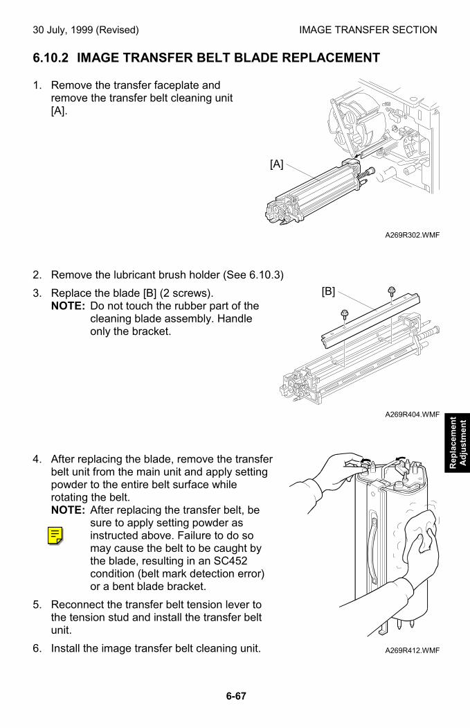
30 July, 1999 (Revised) IMAGE TRANSFER SECTION
6-67
Rep
lace
men
tA
dju
stm
ent
6.10.2 IMAGE TRANSFER BELT BLADE REPLACEMENT
1. Remove the transfer faceplate andremove the transfer belt cleaning unit[A].
2. Remove the lubricant brush holder (See 6.10.3)
3. Replace the blade [B] (2 screws).NOTE: Do not touch the rubber part of the
cleaning blade assembly. Handleonly the bracket.
4. After replacing the blade, remove the transferbelt unit from the main unit and apply settingpowder to the entire belt surface whilerotating the belt.NOTE: After replacing the transfer belt, be
sure to apply setting powder asinstructed above. Failure to do somay cause the belt to be caught bythe blade, resulting in an SC452condition (belt mark detection error)or a bent blade bracket.
5. Reconnect the transfer belt tension lever tothe tension stud and install the transfer beltunit.
6. Install the image transfer belt cleaning unit.
A269R302.WMF
A269R404.WMF
A269R412.WMF
[A]
[B]
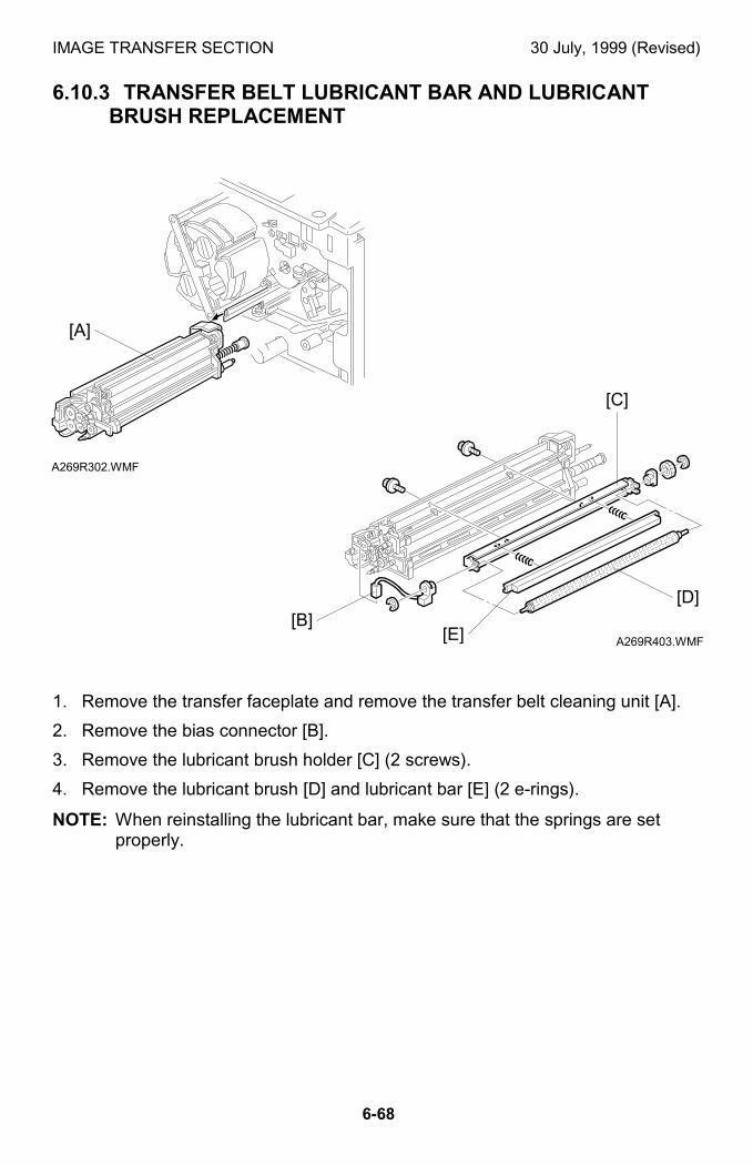
IMAGE TRANSFER SECTION 30 July, 1999 (Revised)
6-68
6.10.3 TRANSFER BELT LUBRICANT BAR AND LUBRICANTBRUSH REPLACEMENT
1. Remove the transfer faceplate and remove the transfer belt cleaning unit [A].
2. Remove the bias connector [B].
3. Remove the lubricant brush holder [C] (2 screws).
4. Remove the lubricant brush [D] and lubricant bar [E] (2 e-rings).
NOTE: When reinstalling the lubricant bar, make sure that the springs are setproperly.
A269R302.WMF
A269R403.WMF
[A]
[D]
[C]
[B][E]
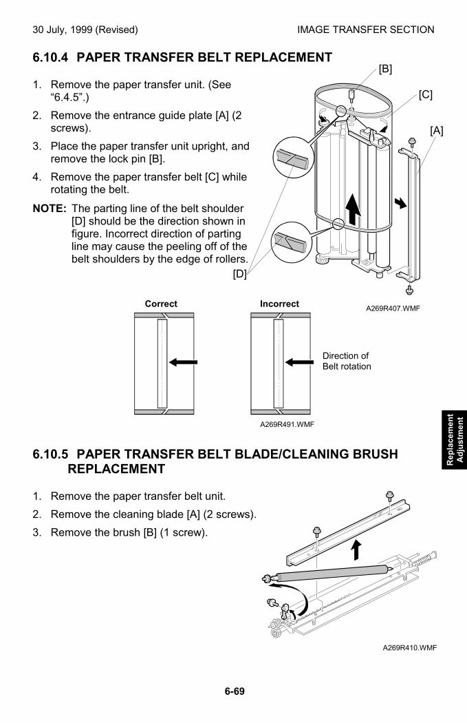
30 July, 1999 (Revised) IMAGE TRANSFER SECTION
6-69
Rep
lace
men
tA
dju
stm
ent
6.10.4 PAPER TRANSFER BELT REPLACEMENT
1. Remove the paper transfer unit. (See“6.4.5”.)
2. Remove the entrance guide plate [A] (2screws).
3. Place the paper transfer unit upright, andremove the lock pin [B].
4. Remove the paper transfer belt [C] whilerotating the belt.
NOTE: The parting line of the belt shoulder[D] should be the direction shown infigure. Incorrect direction of partingline may cause the peeling off of thebelt shoulders by the edge of rollers.
6.10.5 PAPER TRANSFER BELT BLADE/CLEANING BRUSH REPLACEMENT
1. Remove the paper transfer belt unit.
2. Remove the cleaning blade [A] (2 screws).
3. Remove the brush [B] (1 screw).
A269R407.WMF
A269R491.WMF
A269R410.WMF
[B]
[A]
[C]
[D]
Correct Incorrect
Direction ofBelt rotation
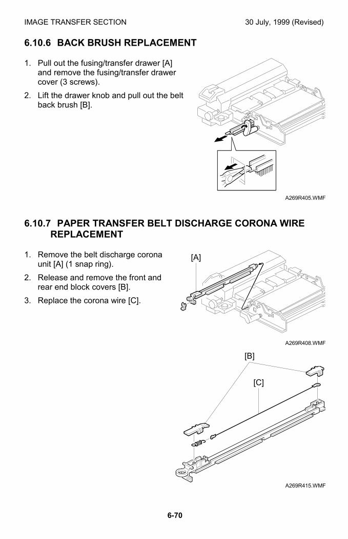
IMAGE TRANSFER SECTION 30 July, 1999 (Revised)
6-70
6.10.6 BACK BRUSH REPLACEMENT
1. Pull out the fusing/transfer drawer [A]and remove the fusing/transfer drawercover (3 screws).
2. Lift the drawer knob and pull out the beltback brush [B].
6.10.7 PAPER TRANSFER BELT DISCHARGE CORONA WIREREPLACEMENT
1. Remove the belt discharge coronaunit [A] (1 snap ring).
2. Release and remove the front andrear end block covers [B].
3. Replace the corona wire [C].
A269R405.WMF
A269R408.WMF
A269R415.WMF
[A]
[B]
[C]
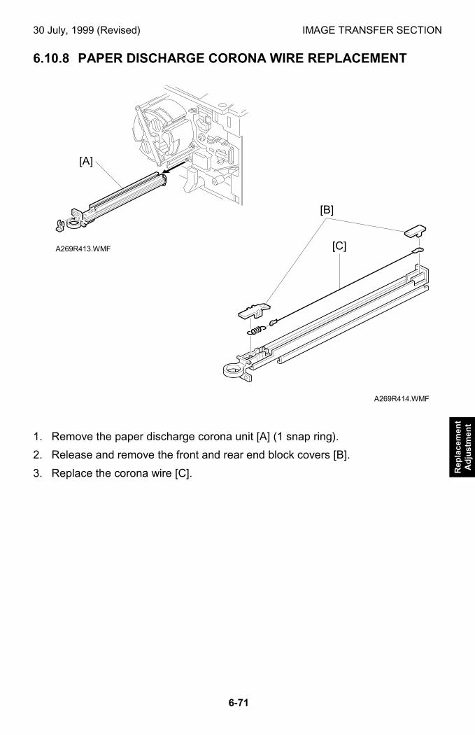
30 July, 1999 (Revised) IMAGE TRANSFER SECTION
6-71
Rep
lace
men
tA
dju
stm
ent
6.10.8 PAPER DISCHARGE CORONA WIRE REPLACEMENT
1. Remove the paper discharge corona unit [A] (1 snap ring).
2. Release and remove the front and rear end block covers [B].
3. Replace the corona wire [C].
A269R413.WMF
A269R414.WMF
[A]
[B]
[C]
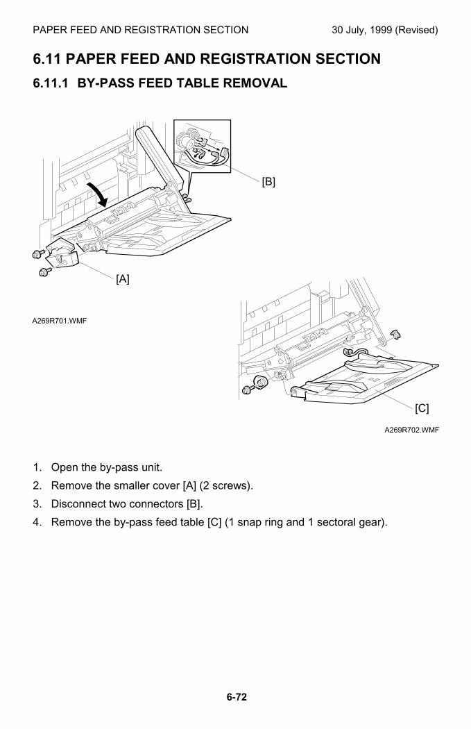
PAPER FEED AND REGISTRATION SECTION 30 July, 1999 (Revised)
6-72
6.11 PAPER FEED AND REGISTRATION SECTION
6.11.1 BY-PASS FEED TABLE REMOVAL
1. Open the by-pass unit.
2. Remove the smaller cover [A] (2 screws).
3. Disconnect two connectors [B].
4. Remove the by-pass feed table [C] (1 snap ring and 1 sectoral gear).
A269R701.WMF
A269R702.WMF
[A]
[B]
[C]
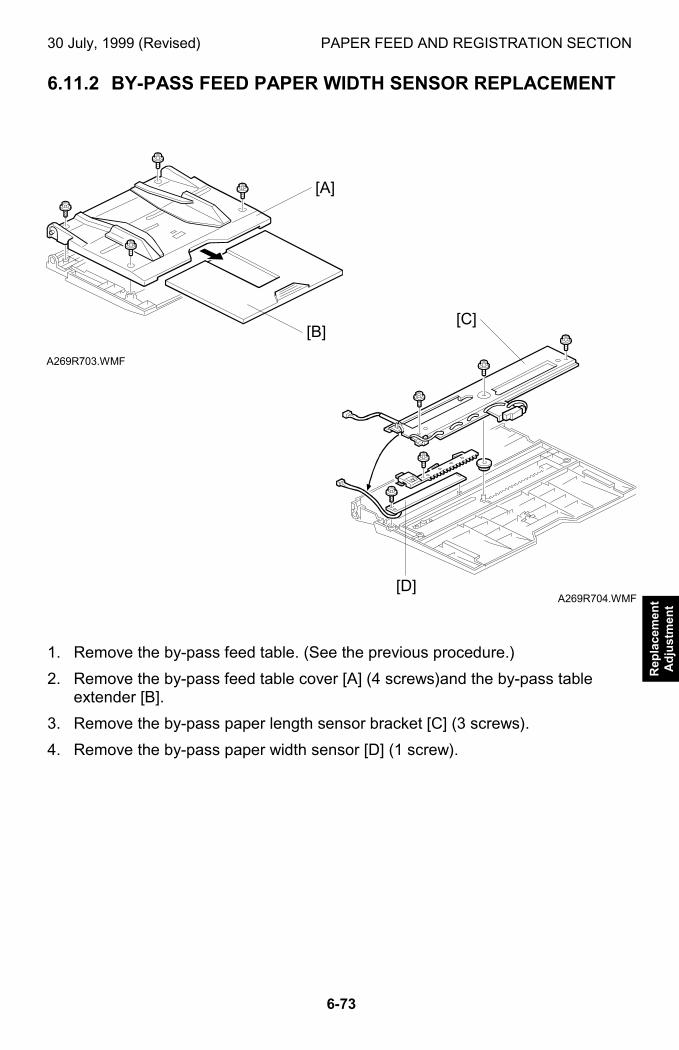
30 July, 1999 (Revised) PAPER FEED AND REGISTRATION SECTION
6-73
Rep
lace
men
tA
dju
stm
ent
6.11.2 BY-PASS FEED PAPER WIDTH SENSOR REPLACEMENT
1. Remove the by-pass feed table. (See the previous procedure.)
2. Remove the by-pass feed table cover [A] (4 screws)and the by-pass tableextender [B].
3. Remove the by-pass paper length sensor bracket [C] (3 screws).
4. Remove the by-pass paper width sensor [D] (1 screw).
A269R703.WMF
A269R704.WMF
[B]
[D]
[C]
[A]
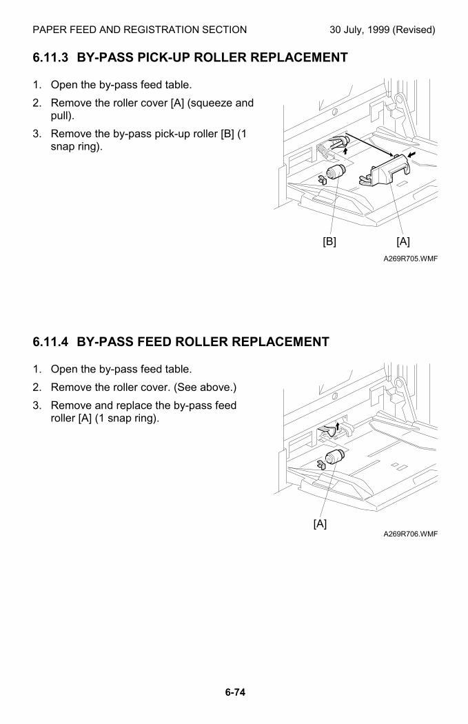
PAPER FEED AND REGISTRATION SECTION 30 July, 1999 (Revised)
6-74
6.11.3 BY-PASS PICK-UP ROLLER REPLACEMENT
1. Open the by-pass feed table.
2. Remove the roller cover [A] (squeeze andpull).
3. Remove the by-pass pick-up roller [B] (1snap ring).
6.11.4 BY-PASS FEED ROLLER REPLACEMENT
1. Open the by-pass feed table.
2. Remove the roller cover. (See above.)
3. Remove and replace the by-pass feedroller [A] (1 snap ring).
A269R705.WMF
A269R706.WMF
[A]
[A]
[B]
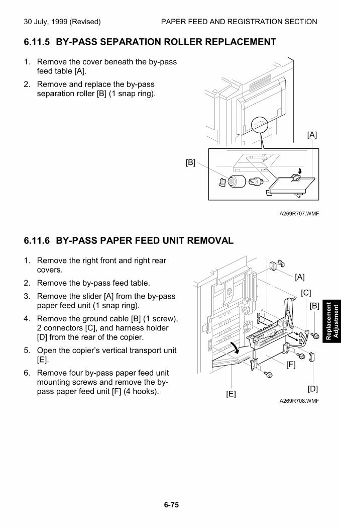
30 July, 1999 (Revised) PAPER FEED AND REGISTRATION SECTION
6-75
Rep
lace
men
tA
dju
stm
ent
6.11.5 BY-PASS SEPARATION ROLLER REPLACEMENT
1. Remove the cover beneath the by-passfeed table [A].
2. Remove and replace the by-passseparation roller [B] (1 snap ring).
6.11.6 BY-PASS PAPER FEED UNIT REMOVAL
1. Remove the right front and right rearcovers.
2. Remove the by-pass feed table.
3. Remove the slider [A] from the by-passpaper feed unit (1 snap ring).
4. Remove the ground cable [B] (1 screw),2 connectors [C], and harness holder[D] from the rear of the copier.
5. Open the copier’s vertical transport unit[E].
6. Remove four by-pass paper feed unitmounting screws and remove the by-pass paper feed unit [F] (4 hooks).
A269R707.WMF
A269R708.WMF
[A]
[B]
[C]
[A]
[B]
[F]
[D][E]
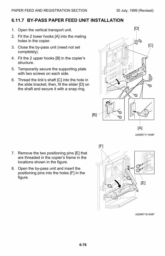
PAPER FEED AND REGISTRATION SECTION 30 July, 1999 (Revised)
6-76
6.11.7 BY-PASS PAPER FEED UNIT INSTALLATION
1. Open the vertical transport unit.
2. Fit the 2 lower hooks [A] into the matingholes in the copier.
3. Close the by-pass unit (need not setcompletely).
4. Fit the 2 upper hooks [B] in the copier’sstructure.
5. Temporarily secure the supporting platewith two screws on each side.
6. Thread the link’s shaft [C] into the hole inthe slide bracket; then, fit the slider [D] onthe shaft and secure it with a snap ring.
7. Remove the two positioning pins [E] thatare threaded in the copier’s frame in thelocations shown in the figure.
8. Open the by-pass unit and insert thepositioning pins into the holes [F] in thefigure.
A269R717.WMF
A269R718.WMF
[D]
[B]
[E]
[C]
[A]
[F]
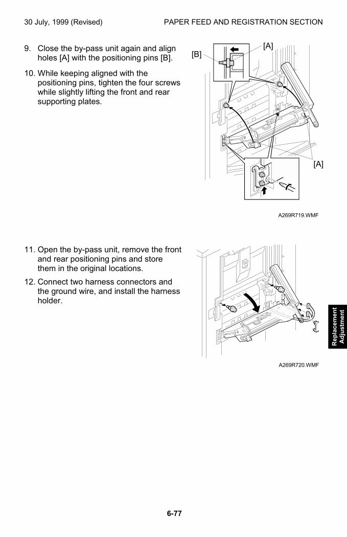
30 July, 1999 (Revised) PAPER FEED AND REGISTRATION SECTION
6-77
Rep
lace
men
tA
dju
stm
ent
9. Close the by-pass unit again and alignholes [A] with the positioning pins [B].
10. While keeping aligned with thepositioning pins, tighten the four screwswhile slightly lifting the front and rearsupporting plates.
11. Open the by-pass unit, remove the frontand rear positioning pins and storethem in the original locations.
12. Connect two harness connectors andthe ground wire, and install the harnessholder.
A269R719.WMF
A269R720.WMF
[A]
[B][A]
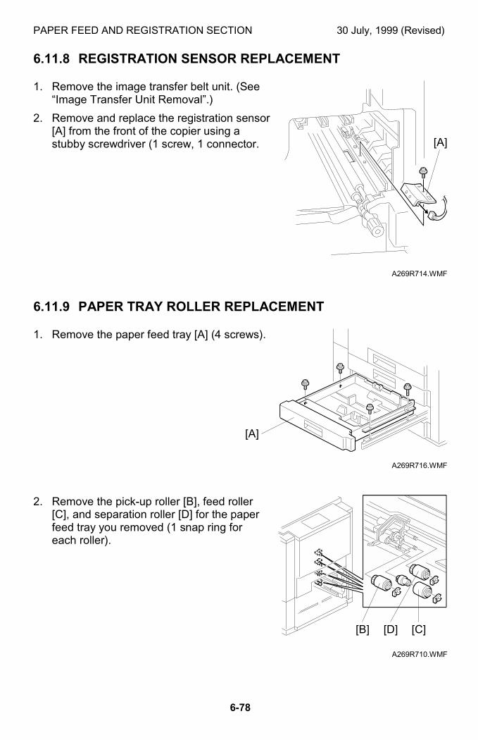
PAPER FEED AND REGISTRATION SECTION 30 July, 1999 (Revised)
6-78
6.11.8 REGISTRATION SENSOR REPLACEMENT
1. Remove the image transfer belt unit. (See“Image Transfer Unit Removal”.)
2. Remove and replace the registration sensor[A] from the front of the copier using astubby screwdriver (1 screw, 1 connector.
6.11.9 PAPER TRAY ROLLER REPLACEMENT
1. Remove the paper feed tray [A] (4 screws).
2. Remove the pick-up roller [B], feed roller[C], and separation roller [D] for the paperfeed tray you removed (1 snap ring foreach roller).
A269R714.WMF
A269R716.WMF
A269R710.WMF
[A]
[A]
[C][B] [D]
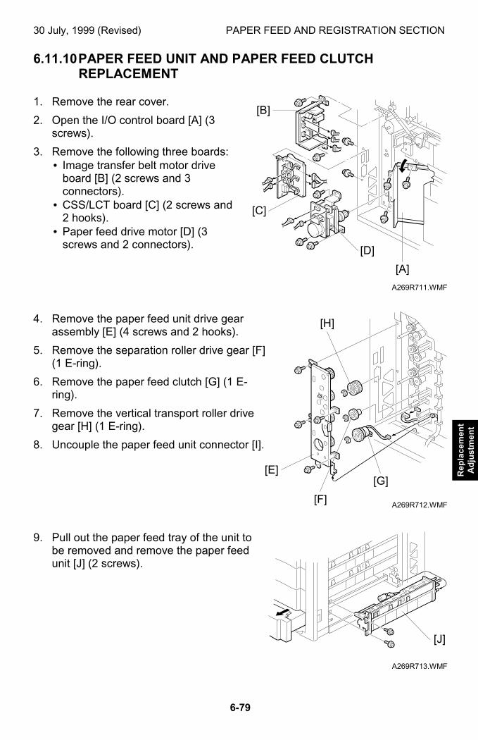
30 July, 1999 (Revised) PAPER FEED AND REGISTRATION SECTION
6-79
Rep
lace
men
tA
dju
stm
ent
6.11.10 PAPER FEED UNIT AND PAPER FEED CLUTCHREPLACEMENT
1. Remove the rear cover.
2. Open the I/O control board [A] (3screws).
3. Remove the following three boards:• Image transfer belt motor drive
board [B] (2 screws and 3connectors).
• CSS/LCT board [C] (2 screws and2 hooks).
• Paper feed drive motor [D] (3screws and 2 connectors).
4. Remove the paper feed unit drive gearassembly [E] (4 screws and 2 hooks).
5. Remove the separation roller drive gear [F](1 E-ring).
6. Remove the paper feed clutch [G] (1 E-ring).
7. Remove the vertical transport roller drivegear [H] (1 E-ring).
8. Uncouple the paper feed unit connector [I].
9. Pull out the paper feed tray of the unit tobe removed and remove the paper feedunit [J] (2 screws).
A269R711.WMF
A269R712.WMF
A269R713.WMF
[C]
[A]
[E]
[H]
[J]
[B]
[D]
[G]
[F]
PAPER FEED AND REGISTRATION SECTION 30 July, 1999 (Revised)
6-80
6.11.11 COPY IMAGE AREA ADJUSTMENT
Adjust the leading edge registration for each paper type and line speed (normalpaper, OHP, thick paper 1, thick paper 2). Adjust the side to side registration foreach paper feed station.
Adjustment standards:
• Leading edge margin: 4 ±2 mm• Side to side: 1.5 ±0.5 mm for each side(total margin of 4 mm or less)
1. Place the type paper for which you want to perform the registration adjustmentin the paper feed tray.
2. Enter the SP2-101 mode and return all the settings to “0.0” (default value).
3. Generate a trim pattern.1) Enter the SP5-955 mode and select “Print Margin” from the list of internal
patterns shown in the popup window.2) Press the Interrupt key to temporarily exit the SP mode screen, select the
“Black & White” and the paper feed tray to be adjusted, then press the Startkey to generate the crop mark trim pattern.
3) Press the Interrupt key again to return to the SP mode screen.
4. Perform the leading edge registration adjustment.Standard value: 4 ±1 mm1) Enter the SP1-1 mode (Lead Edge Regist).2) Select the adjustment conditions.
a) Nrml Paper (Normal paper)b) OHPc) Thk (Thick paper 1)d) Super Thk (Thick Paper 2)
3) Type a number in “Data Input” on the screen from the numeric keypad on theoperation panel. Input a larger value to increase the leading edge margin [A]or a smaller value to decrease the leading edge margin.
Input value range: –4.9 to 4.9
• To enter a negative number, press the ! key before typing the value.• You need not enter a decimal point. For example, to enter “ –1.4,” type:
! → ! → "4) After entering a number, press # (Enter key) to save the number in “Set
Data”.
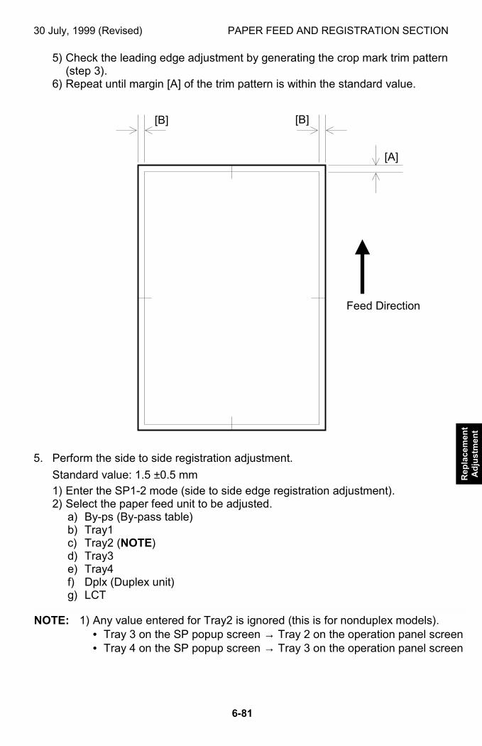
30 July, 1999 (Revised) PAPER FEED AND REGISTRATION SECTION
6-81
Rep
lace
men
tA
dju
stm
ent
5) Check the leading edge adjustment by generating the crop mark trim pattern(step 3).
6) Repeat until margin [A] of the trim pattern is within the standard value.
5. Perform the side to side registration adjustment.
Standard value: 1.5 ±0.5 mm
1) Enter the SP1-2 mode (side to side edge registration adjustment).2) Select the paper feed unit to be adjusted.
a) By-ps (By-pass table)b) Tray1c) Tray2 (NOTE)d) Tray3e) Tray4f) Dplx (Duplex unit)g) LCT
NOTE: 1) Any value entered for Tray2 is ignored (this is for nonduplex models).• Tray 3 on the SP popup screen → Tray 2 on the operation panel screen• Tray 4 on the SP popup screen → Tray 3 on the operation panel screen
[A]
[B][B]
Feed Direction
PAPER FEED AND REGISTRATION SECTION 30 July, 1999 (Revised)
6-82
2) Type a number in “Data Input” on the screen from the numeric keypadon the operation panel. Input a larger value to shift right or a smallervalue shift left (when viewing in the direction of paper feed).Input value range: –4.9 to 4.9• To enter a negative number, press the ! key before typing the
value.• You need not enter a decimal point. For example, to enter “ –1.4,”
type:
! → ! → "3) After entering a number, press # (Enter key) to save the number in “Set
Data”.4) Check the side-to-side registration adjustment by generating the crop
mark trim pattern (step 3).5) Repeat until margin [B] in the trim pattern is within the standard value.
NOTE: After the registration adjustment, press the pattern that is selected in theSP5-955’s popup window (identified by highlight) to restore the originalstate. Otherwise, normal copy operation cannot be resumed. You mayrestore the original copy state by switching off and on the main powerswitch.
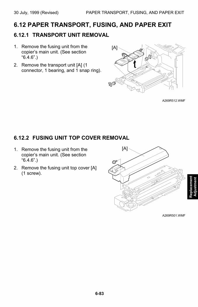
30 July, 1999 (Revised) PAPER TRANSPORT, FUSING, AND PAPER EXIT
6-83
Rep
lace
men
tA
dju
stm
ent
6.12 PAPER TRANSPORT, FUSING, AND PAPER EXIT
6.12.1 TRANSPORT UNIT REMOVAL
1. Remove the fusing unit from thecopier’s main unit. (See section“6.4.6”.)
2. Remove the transport unit [A] (1connector, 1 bearing, and 1 snap ring).
6.12.2 FUSING UNIT TOP COVER REMOVAL
1. Remove the fusing unit from thecopier’s main unit. (See section“6.4.6”.)
2. Remove the fusing unit top cover [A](1 screw).
A269R512.WMF
A269R501.WMF
[A]
[A]
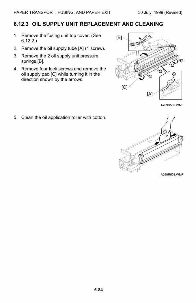
PAPER TRANSPORT, FUSING, AND PAPER EXIT 30 July, 1999 (Revised)
6-84
6.12.3 OIL SUPPLY UNIT REPLACEMENT AND CLEANING
1. Remove the fusing unit top cover. (See6.12.2.)
2. Remove the oil supply tube [A] (1 screw).
3. Remove the 2 oil supply unit pressuresprings [B].
4. Remove four lock screws and remove theoil supply pad [C] while turning it in thedirection shown by the arrows.
5. Clean the oil application roller with cotton.
A269R502.WMF
A269R503.WMF
[B]
[C]
[A]
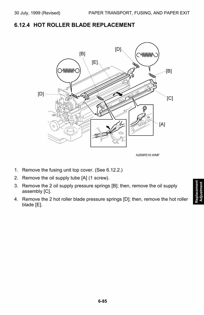
30 July, 1999 (Revised) PAPER TRANSPORT, FUSING, AND PAPER EXIT
6-85
Rep
lace
men
tA
dju
stm
ent
6.12.4 HOT ROLLER BLADE REPLACEMENT
1. Remove the fusing unit top cover. (See 6.12.2.)
2. Remove the oil supply tube [A] (1 screw).
3. Remove the 2 oil supply pressure springs [B]; then, remove the oil supplyassembly [C].
4. Remove the 2 hot roller blade pressure springs [D]; then, remove the hot rollerblade [E].
A269R516.WMF
[D]
[A]
[C]
[B]
[D]
[E]
[B]
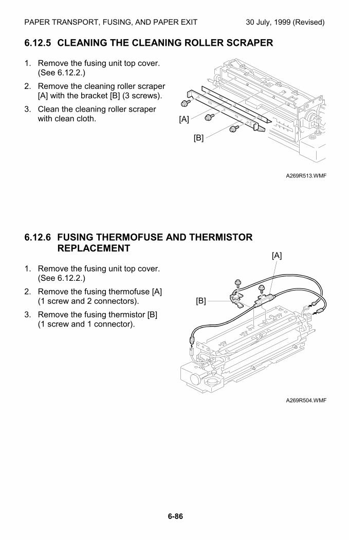
PAPER TRANSPORT, FUSING, AND PAPER EXIT 30 July, 1999 (Revised)
6-86
6.12.5 CLEANING THE CLEANING ROLLER SCRAPER
1. Remove the fusing unit top cover.(See 6.12.2.)
2. Remove the cleaning roller scraper[A] with the bracket [B] (3 screws).
3. Clean the cleaning roller scraperwith clean cloth.
6.12.6 FUSING THERMOFUSE AND THERMISTORREPLACEMENT
1. Remove the fusing unit top cover.(See 6.12.2.)
2. Remove the fusing thermofuse [A](1 screw and 2 connectors).
3. Remove the fusing thermistor [B](1 screw and 1 connector).
A269R513.WMF
A269R504.WMF
[A]
[B]
[A]
[B]
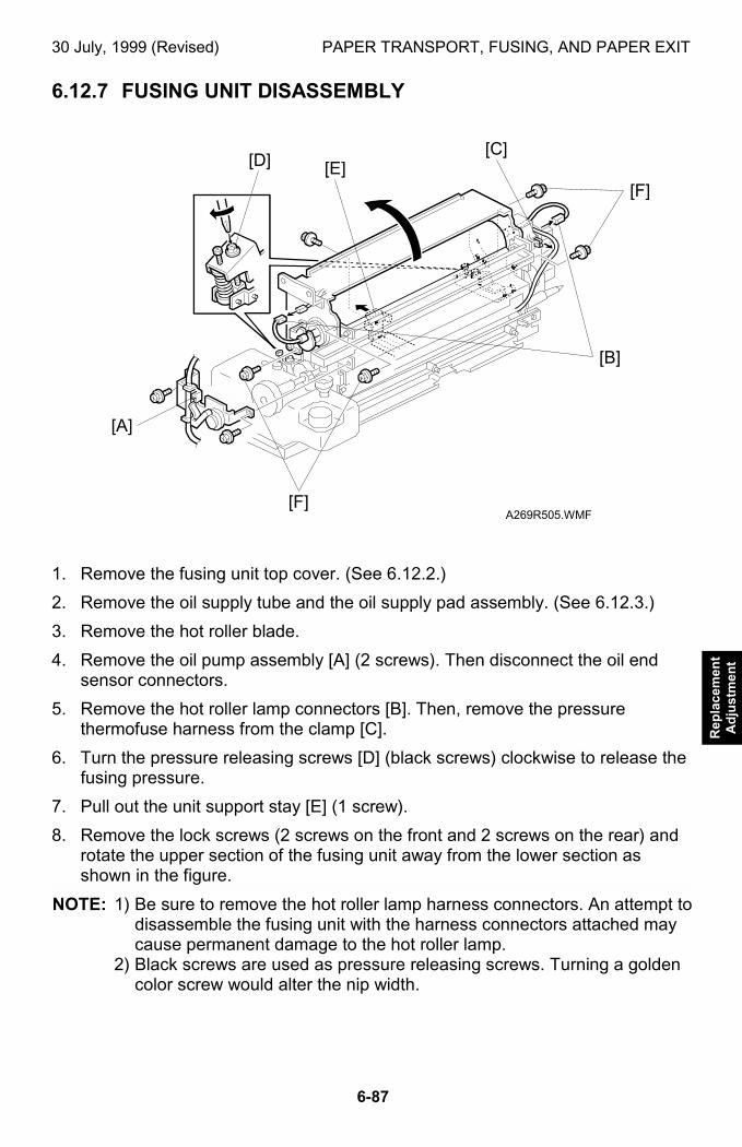
30 July, 1999 (Revised) PAPER TRANSPORT, FUSING, AND PAPER EXIT
6-87
Rep
lace
men
tA
dju
stm
ent
6.12.7 FUSING UNIT DISASSEMBLY
1. Remove the fusing unit top cover. (See 6.12.2.)
2. Remove the oil supply tube and the oil supply pad assembly. (See 6.12.3.)
3. Remove the hot roller blade.
4. Remove the oil pump assembly [A] (2 screws). Then disconnect the oil endsensor connectors.
5. Remove the hot roller lamp connectors [B]. Then, remove the pressurethermofuse harness from the clamp [C].
6. Turn the pressure releasing screws [D] (black screws) clockwise to release thefusing pressure.
7. Pull out the unit support stay [E] (1 screw).
8. Remove the lock screws (2 screws on the front and 2 screws on the rear) androtate the upper section of the fusing unit away from the lower section asshown in the figure.
NOTE: 1) Be sure to remove the hot roller lamp harness connectors. An attempt todisassemble the fusing unit with the harness connectors attached maycause permanent damage to the hot roller lamp.
2) Black screws are used as pressure releasing screws. Turning a goldencolor screw would alter the nip width.
A269R505.WMF
[A]
[F]
[B]
[F]
[C][E][D]
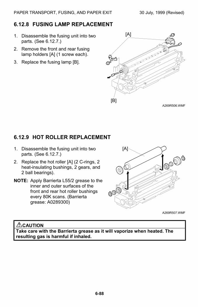
PAPER TRANSPORT, FUSING, AND PAPER EXIT 30 July, 1999 (Revised)
6-88
6.12.8 FUSING LAMP REPLACEMENT
1. Disassemble the fusing unit into twoparts. (See 6.12.7.)
2. Remove the front and rear fusinglamp holders [A] (1 screw each).
3. Replace the fusing lamp [B].
6.12.9 HOT ROLLER REPLACEMENT
1. Disassemble the fusing unit into twoparts. (See 6.12.7.)
2. Replace the hot roller [A] (2 C-rings, 2heat-insulating bushings, 2 gears, and2 ball bearings).
NOTE: Apply Barrierta L55/2 grease to theinner and outer surfaces of thefront and rear hot roller bushingsevery 80K scans. (Barriertagrease: A0289300)
$CAUTIONTake care with the Barrierta grease as it will vaporize when heated. Theresulting gas is harmful if inhaled.
A269R506.WMF
A269R507.WMF
[B]
[A]
[A]
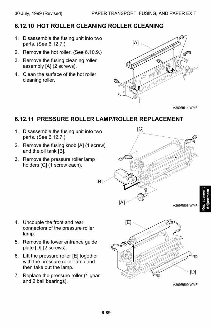
30 July, 1999 (Revised) PAPER TRANSPORT, FUSING, AND PAPER EXIT
6-89
Rep
lace
men
tA
dju
stm
ent
6.12.10 HOT ROLLER CLEANING ROLLER CLEANING
1. Disassemble the fusing unit into twoparts. (See 6.12.7.)
2. Remove the hot roller. (See 6.10.9.)
3. Remove the fusing cleaning rollerassembly [A] (2 screws).
4. Clean the surface of the hot rollercleaning roller.
6.12.11 PRESSURE ROLLER LAMP/ROLLER REPLACEMENT
1. Disassemble the fusing unit into twoparts. (See 6.12.7.)
2. Remove the fusing knob [A] (1 screw)and the oil tank [B].
3. Remove the pressure roller lampholders [C] (1 screw each).
4. Uncouple the front and rearconnectors of the pressure rollerlamp.
5. Remove the lower entrance guideplate [D] (2 screws).
6. Lift the pressure roller [E] togetherwith the pressure roller lamp andthen take out the lamp.
7. Replace the pressure roller (1 gearand 2 ball bearings).
A269R514.WMF
A269R508.WMF
A269R509.WMF
[A]
[A]
[C]
[E]
[B]
[D]
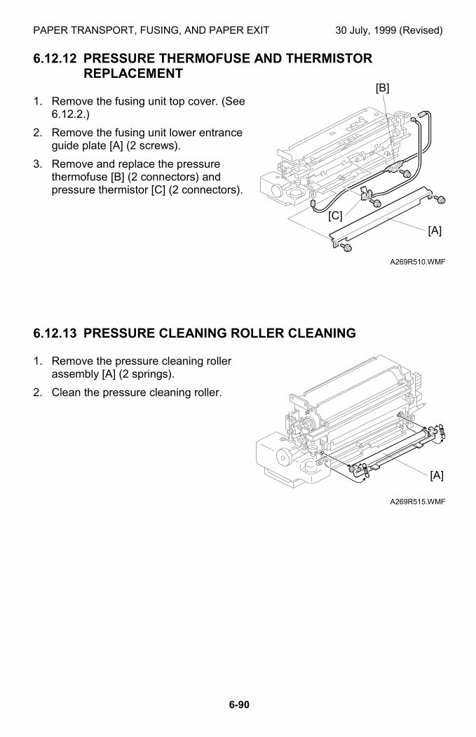
PAPER TRANSPORT, FUSING, AND PAPER EXIT 30 July, 1999 (Revised)
6-90
6.12.12 PRESSURE THERMOFUSE AND THERMISTORREPLACEMENT
1. Remove the fusing unit top cover. (See6.12.2.)
2. Remove the fusing unit lower entranceguide plate [A] (2 screws).
3. Remove and replace the pressurethermofuse [B] (2 connectors) andpressure thermistor [C] (2 connectors).
6.12.13 PRESSURE CLEANING ROLLER CLEANING
1. Remove the pressure cleaning rollerassembly [A] (2 springs).
2. Clean the pressure cleaning roller.
A269R510.WMF
A269R515.WMF
[A]
[B]
[A]
[C]
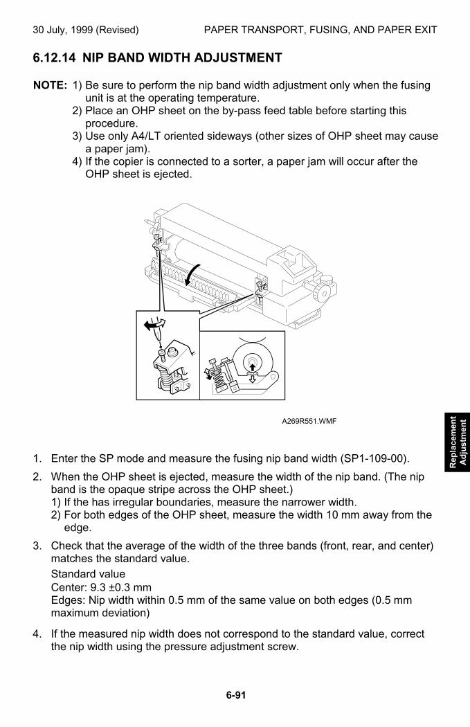
30 July, 1999 (Revised) PAPER TRANSPORT, FUSING, AND PAPER EXIT
6-91
Rep
lace
men
tA
dju
stm
ent
6.12.14 NIP BAND WIDTH ADJUSTMENT
NOTE: 1) Be sure to perform the nip band width adjustment only when the fusingunit is at the operating temperature.
2) Place an OHP sheet on the by-pass feed table before starting thisprocedure.
3) Use only A4/LT oriented sideways (other sizes of OHP sheet may causea paper jam).
4) If the copier is connected to a sorter, a paper jam will occur after theOHP sheet is ejected.
1. Enter the SP mode and measure the fusing nip band width (SP1-109-00).
2. When the OHP sheet is ejected, measure the width of the nip band. (The nipband is the opaque stripe across the OHP sheet.)1) If the has irregular boundaries, measure the narrower width.2) For both edges of the OHP sheet, measure the width 10 mm away from the
edge.
3. Check that the average of the width of the three bands (front, rear, and center)matches the standard value.
Standard valueCenter: 9.3 ±0.3 mmEdges: Nip width within 0.5 mm of the same value on both edges (0.5 mmmaximum deviation)
4. If the measured nip width does not correspond to the standard value, correctthe nip width using the pressure adjustment screw.
A269R551.WMF

PAPER TRANSPORT, FUSING, AND PAPER EXIT 30 July, 1999 (Revised)
6-92
6.12.15 CAUTIONS TO BE TAKEN WHEN USING A FUSING UNITTHAT HAS BEEN IN STOCK FOR A LONG PERIOD
NOTE: When using a fusing unit hat has been in stock for an extended period,press the pump with fingers to check whether adequate amount of oil ispumped up.
Reason: A fusing unit that has been stocked unused for a long time mayhave a clogged pump or valve in the oil supply unit. Such a fusing unit willnot work properly. This may result in an oil supply shortage andconsequently an earlier than usual deterioration of the hot roller.
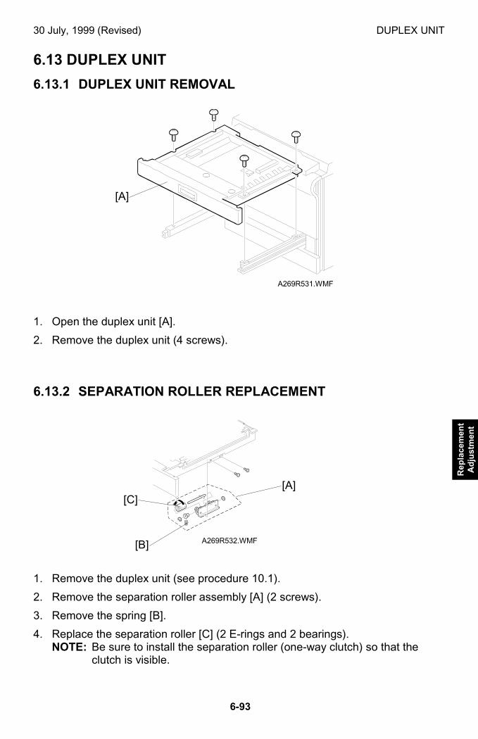
30 July, 1999 (Revised) DUPLEX UNIT
6-93
Rep
lace
men
tA
dju
stm
ent
6.13 DUPLEX UNIT
6.13.1 DUPLEX UNIT REMOVAL
1. Open the duplex unit [A].
2. Remove the duplex unit (4 screws).
6.13.2 SEPARATION ROLLER REPLACEMENT
1. Remove the duplex unit (see procedure 10.1).
2. Remove the separation roller assembly [A] (2 screws).
3. Remove the spring [B].
4. Replace the separation roller [C] (2 E-rings and 2 bearings).NOTE: Be sure to install the separation roller (one-way clutch) so that the
clutch is visible.
A269R531.WMF
A269R532.WMF
[A]
[A]
[B]
[C]
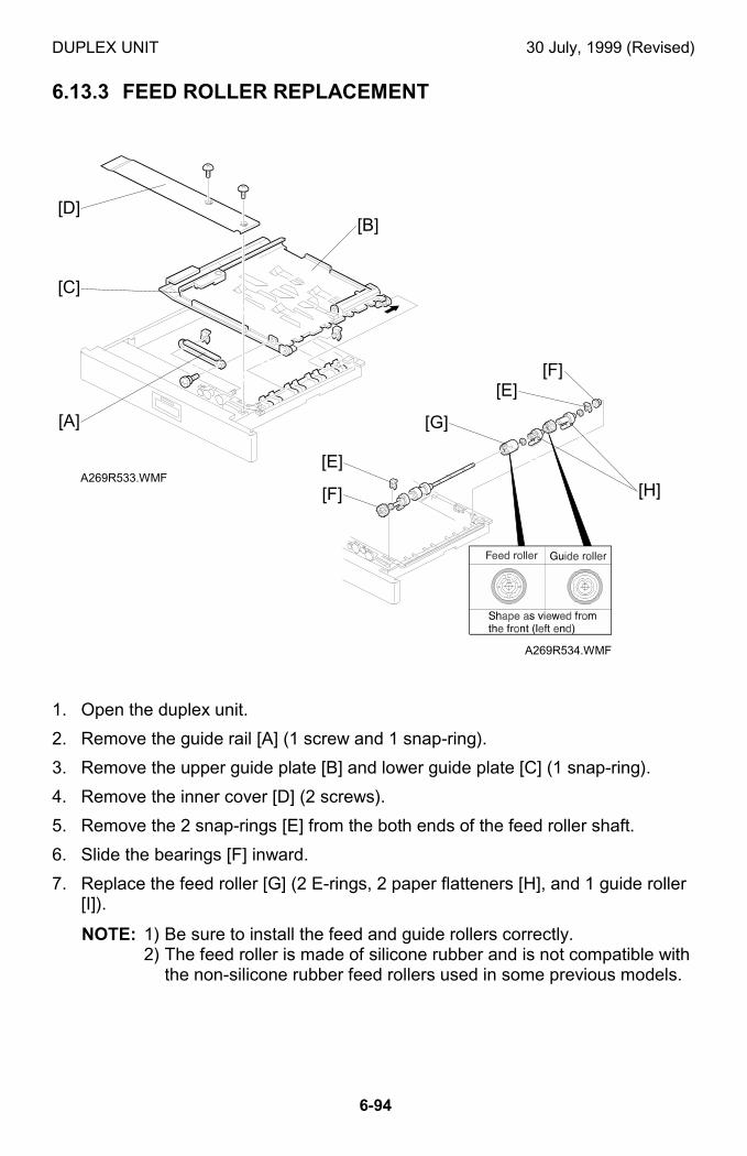
DUPLEX UNIT 30 July, 1999 (Revised)
6-94
6.13.3 FEED ROLLER REPLACEMENT
1. Open the duplex unit.
2. Remove the guide rail [A] (1 screw and 1 snap-ring).
3. Remove the upper guide plate [B] and lower guide plate [C] (1 snap-ring).
4. Remove the inner cover [D] (2 screws).
5. Remove the 2 snap-rings [E] from the both ends of the feed roller shaft.
6. Slide the bearings [F] inward.
7. Replace the feed roller [G] (2 E-rings, 2 paper flatteners [H], and 1 guide roller[I]).
NOTE: 1) Be sure to install the feed and guide rollers correctly.2) The feed roller is made of silicone rubber and is not compatible with
the non-silicone rubber feed rollers used in some previous models.
A269R533.WMF
A269R534.WMF
[A]
[B]
[C]
[D]
[E]
[F]
[G]
[H]
[F][E]
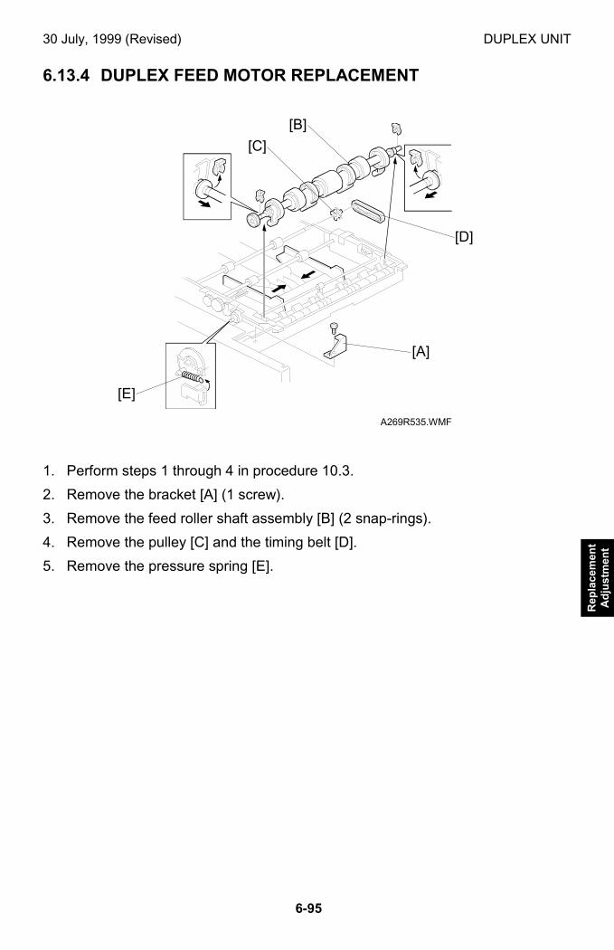
30 July, 1999 (Revised) DUPLEX UNIT
6-95
Rep
lace
men
tA
dju
stm
ent
6.13.4 DUPLEX FEED MOTOR REPLACEMENT
1. Perform steps 1 through 4 in procedure 10.3.
2. Remove the bracket [A] (1 screw).
3. Remove the feed roller shaft assembly [B] (2 snap-rings).
4. Remove the pulley [C] and the timing belt [D].
5. Remove the pressure spring [E].
A269R535.WMF
[A]
[B]
[C]
[D]
[E]
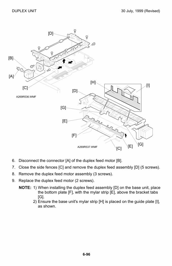
DUPLEX UNIT 30 July, 1999 (Revised)
6-96
6. Disconnect the connector [A] of the duplex feed motor [B].
7. Close the side fences [C] and remove the duplex feed assembly [D] (5 screws).
8. Remove the duplex feed motor assembly (3 screws).
9. Replace the duplex feed motor (2 screws).
NOTE: 1) When installing the duplex feed assembly [D] on the base unit, placethe bottom plate [F], with the mylar strip [E], above the bracket tabs[G].
2) Ensure the base unit's mylar strip [H] is placed on the guide plate [I],as shown.
A269R536.WMF
A269R537.WMF
[A]
[B]
[C]
[D]
[D]
[E]
[F]
[G]
[H][I]
[C] [E] [G]
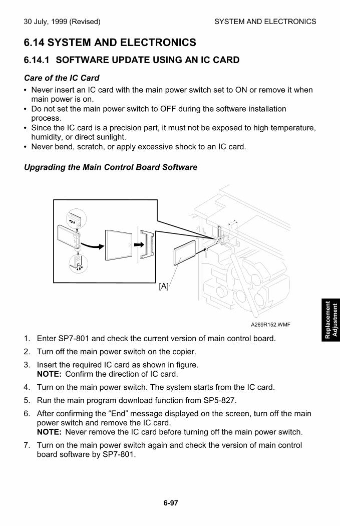
30 July, 1999 (Revised) SYSTEM AND ELECTRONICS
6-97
Rep
lace
men
tA
dju
stm
ent
6.14 SYSTEM AND ELECTRONICS
6.14.1 SOFTWARE UPDATE USING AN IC CARD
Care of the IC Card
• Never insert an IC card with the main power switch set to ON or remove it whenmain power is on.
• Do not set the main power switch to OFF during the software installationprocess.
• Since the IC card is a precision part, it must not be exposed to high temperature,humidity, or direct sunlight.
• Never bend, scratch, or apply excessive shock to an IC card.
Upgrading the Main Control Board Software
1. Enter SP7-801 and check the current version of main control board.
2. Turn off the main power switch on the copier.
3. Insert the required IC card as shown in figure.NOTE: Confirm the direction of IC card.
4. Turn on the main power switch. The system starts from the IC card.
5. Run the main program download function from SP5-827.
6. After confirming the “End” message displayed on the screen, turn off the mainpower switch and remove the IC card.NOTE: Never remove the IC card before turning off the main power switch.
7. Turn on the main power switch again and check the version of main controlboard software by SP7-801.
A269R152.WMF
[A]
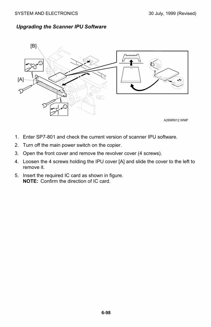
SYSTEM AND ELECTRONICS 30 July, 1999 (Revised)
6-98
Upgrading the Scanner IPU Software
1. Enter SP7-801 and check the current version of scanner IPU software.
2. Turn off the main power switch on the copier.
3. Open the front cover and remove the revolver cover (4 screws).
4. Loosen the 4 screws holding the IPU cover [A] and slide the cover to the left toremove it.
5. Insert the required IC card as shown in figure.NOTE: Confirm the direction of IC card.
A269R912.WMF
[A]
[B]
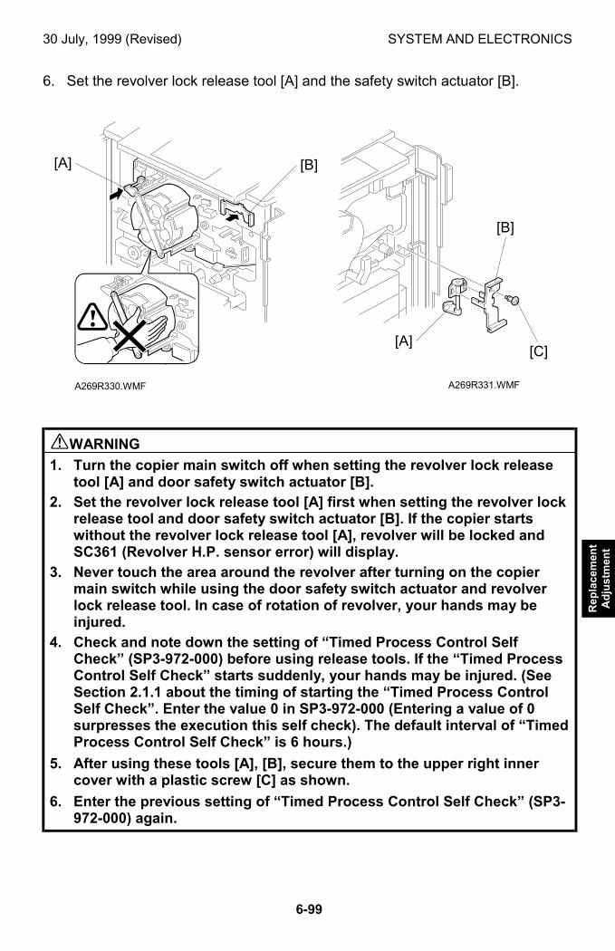
30 July, 1999 (Revised) SYSTEM AND ELECTRONICS
6-99
Rep
lace
men
tA
dju
stm
ent
6. Set the revolver lock release tool [A] and the safety switch actuator [B].
$WARNING
1. Turn the copier main switch off when setting the revolver lock releasetool [A] and door safety switch actuator [B].
2. Set the revolver lock release tool [A] first when setting the revolver lockrelease tool and door safety switch actuator [B]. If the copier startswithout the revolver lock release tool [A], revolver will be locked andSC361 (Revolver H.P. sensor error) will display.
3. Never touch the area around the revolver after turning on the copiermain switch while using the door safety switch actuator and revolverlock release tool. In case of rotation of revolver, your hands may beinjured.
4. Check and note down the setting of “Timed Process Control SelfCheck” (SP3-972-000) before using release tools. If the “Timed ProcessControl Self Check” starts suddenly, your hands may be injured. (SeeSection 2.1.1 about the timing of starting the “Timed Process ControlSelf Check”. Enter the value 0 in SP3-972-000 (Entering a value of 0surpresses the execution this self check). The default interval of “TimedProcess Control Self Check” is 6 hours.)
5. After using these tools [A], [B], secure them to the upper right innercover with a plastic screw [C] as shown.
6. Enter the previous setting of “Timed Process Control Self Check” (SP3-972-000) again.
A269R331.WMFA269R330.WMF
[B]
[A][C]
[A] [B]
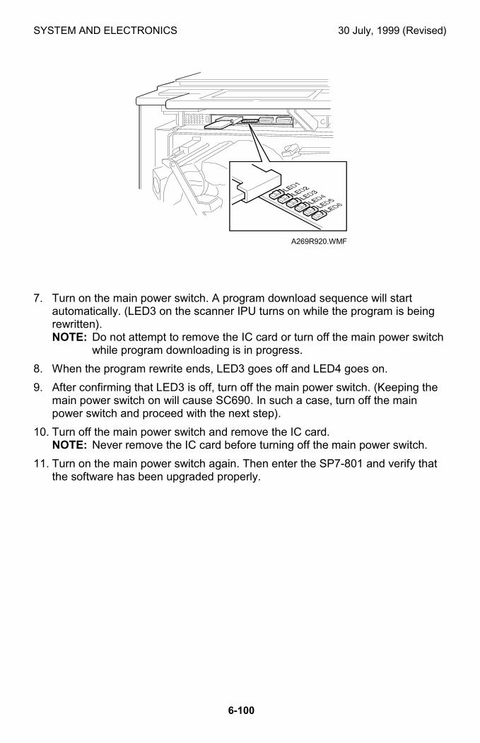
SYSTEM AND ELECTRONICS 30 July, 1999 (Revised)
6-100
7. Turn on the main power switch. A program download sequence will startautomatically. (LED3 on the scanner IPU turns on while the program is beingrewritten).NOTE: Do not attempt to remove the IC card or turn off the main power switch
while program downloading is in progress.
8. When the program rewrite ends, LED3 goes off and LED4 goes on.
9. After confirming that LED3 is off, turn off the main power switch. (Keeping themain power switch on will cause SC690. In such a case, turn off the mainpower switch and proceed with the next step).
10. Turn off the main power switch and remove the IC card.NOTE: Never remove the IC card before turning off the main power switch.
11. Turn on the main power switch again. Then enter the SP7-801 and verify thatthe software has been upgraded properly.
A269R920.WMF
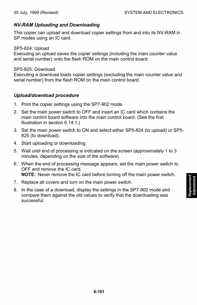
30 July, 1999 (Revised) SYSTEM AND ELECTRONICS
6-101
Rep
lace
men
tA
dju
stm
ent
NV-RAM Uploading and Downloading
This copier can upload and download copier settings from and into its NV-RAM inSP modes using an IC card.
SP5-824: UploadExecuting an upload saves the copier settings (including the main counter valueand serial number) onto the flash ROM on the main control board.
SP5-825: DownloadExecuting a download loads copier settings (excluding the main counter value andserial number) from the flash ROM on the main control board.
Upload/download procedure
1. Print the copier settings using the SP7-902 mode.
2. Set the main power switch to OFF and insert an IC card which contains themain control board software into the main control board. (See the firstillustration in section 6.14.1.)
3. Set the main power switch to ON and select either SP5-824 (to upload) or SP5-825 (to download).
4. Start uploading or downloading.
5. Wait until end of processing is indicated on the screen (approximately 1 to 3minutes, depending on the size of the software).
6. When the end of processing message appears, set the main power switch toOFF and remove the IC card.NOTE: Never remove the IC card before turning off the main power switch.
7. Replace all covers and turn on the main power switch.
8. In the case of a download, display the settings in the SP7-902 mode andcompare them against the old values to verify that the downloading wassuccessful.
SYSTEM AND ELECTRONICS 30 July, 1999 (Revised)
6-102
6.14.2 RAM CLEAR
RAM Clear Procedure
NOTE: Clearing the RAM resets all SP and UP values, except the serial numberand main counter value, to the defaults. It is, therefore, important toperform this step using the procedure shown below.
1. Before clearing the RAM, either:execute SP7-902 to output the SP mode values that have been changed fromtheir default values;orUpload the settings from the NV-RAM onto the flash ROM on main controlboard using the SP5-824 mode. (See “NV-RAM uploading and downloading”.)
2. Use the SP5-801 mode to clear the NV-RAM.
3. Perform the touch panel calibration.NOTE: After the NV-RAM clearing, the touch panel is not effective. Therefore,
the “Touch Panel Calibration” is required (See 6.14.5 Touch PanelCalibration).
4. Run the forced process control self-check (SP3-126). (Potential tableoptimization is required since RAM clearing also initializes the process controldata.)
5. Enter the SP mode changes that were output in step (1), or download the NV-RAM values from the flash ROM on main control board. (See “NV-RAMUploading and Downloading”.)
6. Perform the ACC procedure.
7. If the color balance after the ACC is not correct, adjust the ACC target usingSP4-502 (for copier mode) and SP4-503 (for printer mode).
NOTE: To clear (zero) the counter log data, run the SP7-808 (Clear All Counters).
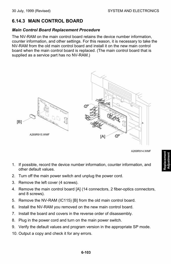
30 July, 1999 (Revised) SYSTEM AND ELECTRONICS
6-103
Rep
lace
men
tA
dju
stm
ent
6.14.3 MAIN CONTROL BOARD
Main Control Board Replacement Procedure
The NV-RAM on the main control board retains the device number information,counter information, and other settings. For this reason, it is necessary to take theNV-RAM from the old main control board and install it on the new main controlboard when the main control board is replaced. (The main control board that issupplied as a service part has no NV-RAM.)
1. If possible, record the device number information, counter information, andother default values.
2. Turn off the main power switch and unplug the power cord.
3. Remove the left cover (4 screws).
4. Remove the main control board [A] (14 connectors, 2 fiber-optics connectors,and 8 screws).
5. Remove the NV-RAM (IC115) [B] from the old main control board.
6. Install the NV-RAM you removed on the new main control board.
7. Install the board and covers in the reverse order of disassembly.
8. Plug in the power cord and turn on the main power switch.
9. Verify the default values and program version in the appropriate SP mode.
10. Output a copy and check it for any errors.
A269R914.WMF
A269R915.WMF
[B]
[A]
SYSTEM AND ELECTRONICS 30 July, 1999 (Revised)
6-104
6.14.4 COUNTERS
About the Total Counter
The total counter value is stored in the NV-RAM on the main control board. Itcannot be reset with RAM clear. Consequently, the NV-RAM in this copiercorresponds to the conventional electronic or mechanical counters and must behandled as such. (See the following procedure–”Precautions to be Observed WhenReplacing the Total Counter (NV-RAM).”)
The factory-set counter value is a negative value. When the total counter has anegative value, it may be reset using SP7-825. However, resetting is disabled if thecounter value is positive. The counter value can be monitored using the counterkey located on the right side of the operation panel.
Mechanical Counter
This copier is also provided with a mechanical counter. This mechanical counter iscovered with a seal because normally it isn't used. This counter has no resetfunction, and no service code will display if it becomes faulty. The mechanicalcounter is set to “0” at the factory. It starts counting when the total counter is resetusing the SP7-825 mode. (If the total counter isn't reset using SP7-825, themechanical counter starts when the total counter reaches “0”.)
NOTE: Normally you shouldn't ever need to peel the seal off of the mechanicalcounter.
30 July, 1999 (Revised) SYSTEM AND ELECTRONICS
6-105
Rep
lace
men
tA
dju
stm
ent
NV-RAM Replacement Procedure
Make sure you have the factory settings that come with the copier before beginningthe following procedure:
1. Use the SP7-902 mode to output the SP mode values that have been modifiedfrom their default value.
2. Set the main power switch to OFF and unplug the power cord.
3. Replace the NV-RAM (IC115) on the main board. (Refer to “Main Control BoardReplacement Procedure”.
4. Reassemble the machine. Then, turn on the main power and enter themachine’s device number in the factory set mode (consult with your managerfor details).
5. Execute SP5-801 (RAM Clear).
6. Enter the SP mode changes you output in step (1).
7. Perform the auto color calibration procedure.
8. If the image needs adjustment after being subject to auto color calibration,calibrate the target using the SP4-502/503 modes.
• The factory-set value of the total counter NV-RAM supplied as a part (A2579099)is –2000±20 for K (development cycles) and –3000±20 for CMY (developmentcycles).
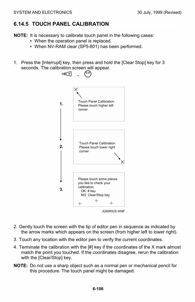
SYSTEM AND ELECTRONICS 30 July, 1999 (Revised)
6-106
6.14.5 TOUCH PANEL CALIBRATION
NOTE: It is necessary to calibrate touch panel in the following cases:• When the operation panel is replaced.• When NV-RAM clear (SP5-801) has been performed.
1. Press the [Interrupt] key, then press and hold the [Clear Stop] key for 3seconds. The calibration screen will appear.
% → &
2. Gently touch the screen with the tip of editor pen in sequence as indicated bythe arrow marks which appears on the screen (from higher left to lower right).
3. Touch any location with the editor pen to verify the current coordinates.
4. Terminate the calibration with the [#] key if the coordinates of the X mark almostmatch the point you touched. If the coordinates disagree, rerun the calibrationwith the [Clear/Stop] key.
NOTE: Do not use a sharp object such as a normal pen or mechanical pencil forthis procedure. The touch panel might be damaged.
Touch Panel Calibration.Please touch higher leftcorner
Touch Panel Calibration.Please touch lower rightcorner
Please touch some placesyou like to check yourcalibration. OK: # key NG: Clear/Stop key
1.
2.
3.
A269R525.WMF
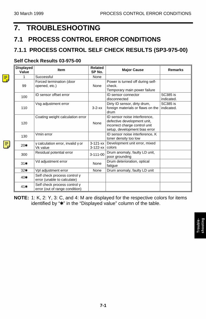
30 March 1999 PROCESS CONTROL ERROR CONDITIONS
7-1
Trou
ble-
shoo
ting
7. TROUBLESHOOTING
7.1 PROCESS CONTROL ERROR CONDITIONS
7.1.1 PROCESS CONTROL SELF CHECK RESULTS (SP3-975-00)
Self Check Results 03-975-00Displayed
Value Item RelatedSP No. Major Cause Remarks
1 Successful None
99Forced termination (dooropened, etc.) None
Power is turned off during self-check.Temporary main power failure
100 ID sensor offset error ID sensor connectordisconnected
SC385 isindicated.
110Vsg adjustment error
3-2-xxDirty ID sensor, dirty drum,foreign materials or flaws on thedrum
SC385 isindicated.
120
Coating weight calculation error
None
ID sensor noise interference,defective development unit,incorrect charge control unitsetup, development bias error
130 Vmin error ID sensor noise interference, Ktoner density too low
204 γ calculation error, invalid γ orVk value
3-121-xx3-122-xx
Development unit error, mixedcolors
300 Residual potential error 3-111-00Drum anomaly, faulty LD unit,poor grounding
314 Vd adjustment error NoneDrum deterioration, opticalfatigue
324 Vpl adjustment error None Drum anomaly, faulty LD unit
404 Self check process control γerror (unable to calculate)
414 Self check process control γerror (out of range condition)
NOTE: 1: K, 2: Y, 3: C, and 4: M are displayed for the respective colors for itemsidentified by “4” in the “Displayed value” column of the table.
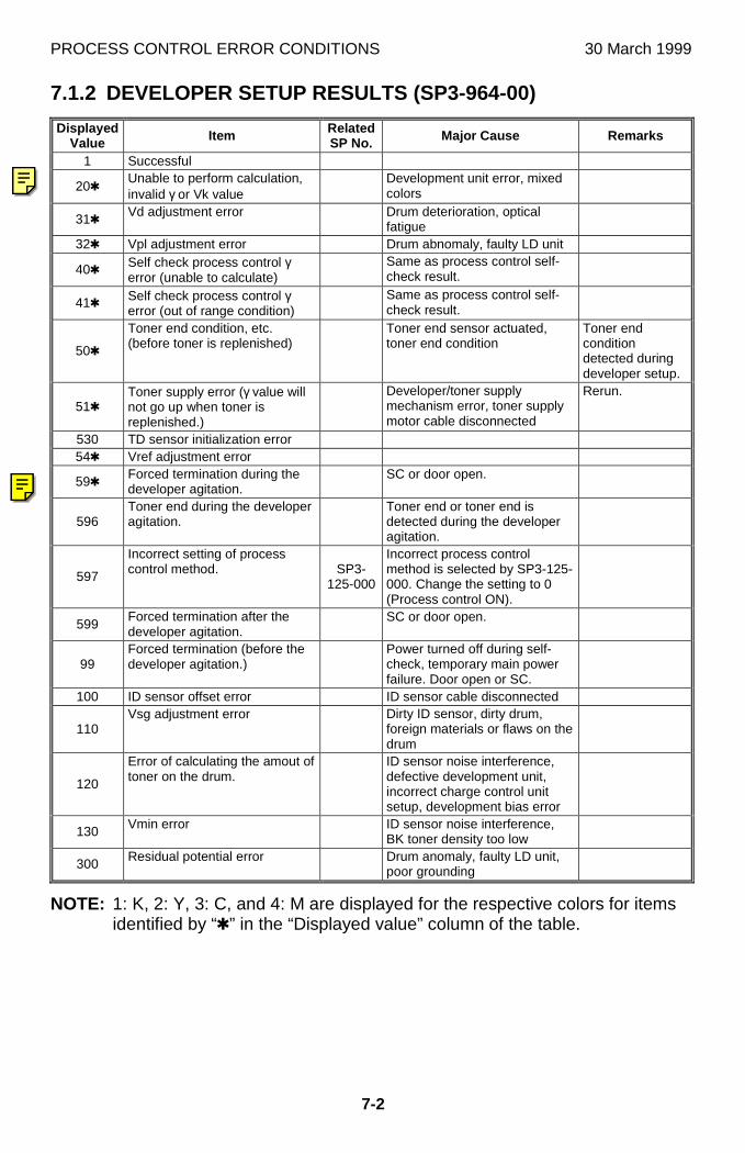
PROCESS CONTROL ERROR CONDITIONS 30 March 1999
7-2
7.1.2 DEVELOPER SETUP RESULTS (SP3-964-00)
DisplayedValue Item Related
SP No. Major Cause Remarks
1 Successful
204Unable to perform calculation,invalid γ or Vk value
Development unit error, mixedcolors
314 Vd adjustment error Drum deterioration, opticalfatigue
324 Vpl adjustment error Drum abnomaly, faulty LD unit
404 Self check process control γerror (unable to calculate)
Same as process control self-check result.
414 Self check process control γerror (out of range condition)
Same as process control self-check result.
504
Toner end condition, etc.(before toner is replenished)
Toner end sensor actuated,toner end condition
Toner endconditiondetected duringdeveloper setup.
514Toner supply error (γ value willnot go up when toner isreplenished.)
Developer/toner supplymechanism error, toner supplymotor cable disconnected
Rerun.
530 TD sensor initialization error544 Vref adjustment error
594 Forced termination during thedeveloper agitation.
SC or door open.
596Toner end during the developeragitation.
Toner end or toner end isdetected during the developeragitation.
597
Incorrect setting of processcontrol method. SP3-
125-000
Incorrect process controlmethod is selected by SP3-125-000. Change the setting to 0(Process control ON).
599Forced termination after thedeveloper agitation.
SC or door open.
99Forced termination (before thedeveloper agitation.)
Power turned off during self-check, temporary main powerfailure. Door open or SC.
100 ID sensor offset error ID sensor cable disconnected
110Vsg adjustment error Dirty ID sensor, dirty drum,
foreign materials or flaws on thedrum
120
Error of calculating the amout oftoner on the drum.
ID sensor noise interference,defective development unit,incorrect charge control unitsetup, development bias error
130 Vmin error ID sensor noise interference,BK toner density too low
300 Residual potential error Drum anomaly, faulty LD unit,poor grounding
NOTE: 1: K, 2: Y, 3: C, and 4: M are displayed for the respective colors for itemsidentified by “4” in the “Displayed value” column of the table.
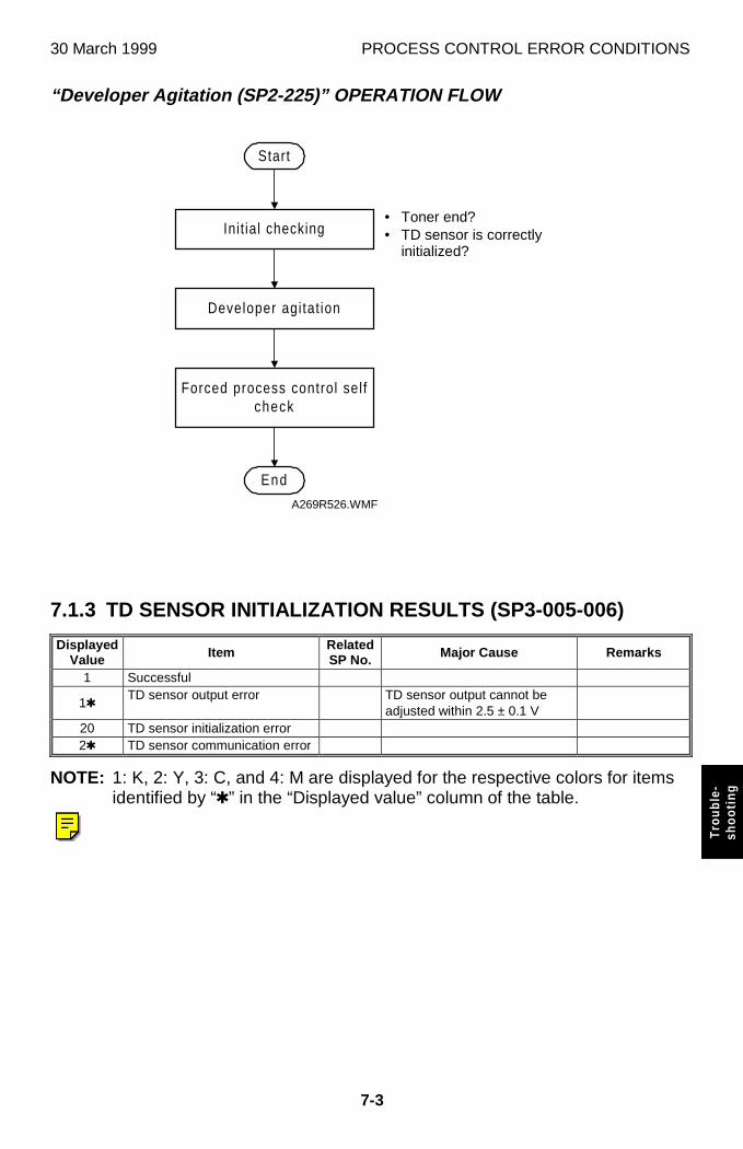
30 March 1999 PROCESS CONTROL ERROR CONDITIONS
7-3
Trou
ble-
shoo
ting
“Developer Agitation (SP2-225)” OPERATION FLOW
7.1.3 TD SENSOR INITIALIZATION RESULTS (SP3-005-006)
DisplayedValue Item Related
SP No. Major Cause Remarks
1 Successful
14TD sensor output error TD sensor output cannot be
adjusted within 2.5 ± 0.1 V20 TD sensor initialization error24 TD sensor communication error
NOTE: 1: K, 2: Y, 3: C, and 4: M are displayed for the respective colors for itemsidentified by “4” in the “Displayed value” column of the table.
Start
Init ial checking
Developer agi tat ion
Forced process control sel fcheck
End
A269R526.WMF
• Toner end?• TD sensor is correctly
initialized?
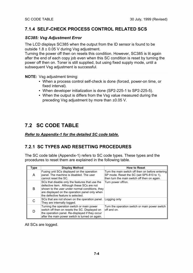
SC CODE TABLE 30 July, 1999 (Revised)
7-4
7.1.4 SELF-CHECK PROCESS CONTROL RELATED SCS
SC385: Vsg Adjustment Error
The LCD displays SC385 when the output from the ID sensor is found to beoutside 1.8 ± 0.05 V during Vsg adjustment.Turning the power off then on resets this condition. However, SC385 is lit againafter the end of each copy job even when this SC condition is reset by turning thepower off then on. Toner is still supplied, but using fixed supply mode, until asubsequent Vsg adjustment is successful.
NOTE: Vsg adjustment timing:• When a process control self-check is done (forced, power-on time, or
fixed interval).• When developer initialization is done (SP2-225-1 to SP2-225-5).• When the output is differs from the Vsg value measured during the
preceding Vsg adjustment by more than ±0.05 V.
7.2 SC CODE TABLE
Refer to Appendix-1 for the detailed SC code table.
7.2.1 SC TYPES AND RESETTING PROCEDURES
The SC code table (Appendix-1) refers to SC code types. These types and theprocedures to reset them are explained in the following table.
Type Display Method How to Reset
AFusing unit SCs displayed on the operationpanel. The machine is disabled. The usercannot reset the SC.
Turn the main switch off then on before enteringSP mode. Reset the SC (set SP5-810 to 1),then turn the main switch off then on again.
B
SCs that disable only the features that use thedefective item. Although these SCs are notshown to the user under normal conditions, theyare displayed on the operation panel only whenthe defective feature is selected.
Turn power off/on.
C SCs that are not shown on the operation panel.They are internally logged.
Logging only
D
Turning the operation switch or main powerswitch off then on resets the SC. Displayed onthe operation panel. Re-displayed if they occurafter the main power switch is turned on again.
Turn the operation switch or main power switchoff and on.
All SCs are logged.
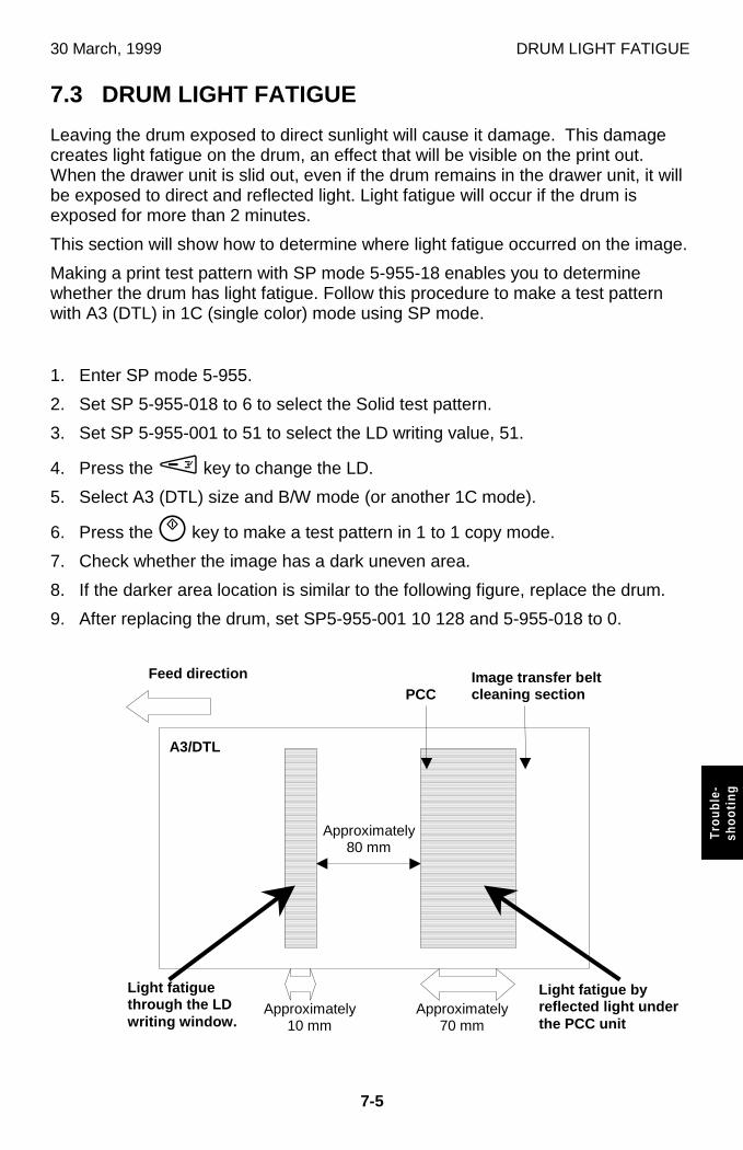
30 March, 1999 DRUM LIGHT FATIGUE
7-5
Trou
ble-
shoo
ting
7.3 DRUM LIGHT FATIGUE
Leaving the drum exposed to direct sunlight will cause it damage. This damagecreates light fatigue on the drum, an effect that will be visible on the print out.When the drawer unit is slid out, even if the drum remains in the drawer unit, it willbe exposed to direct and reflected light. Light fatigue will occur if the drum isexposed for more than 2 minutes.
This section will show how to determine where light fatigue occurred on the image.
Making a print test pattern with SP mode 5-955-18 enables you to determinewhether the drum has light fatigue. Follow this procedure to make a test patternwith A3 (DTL) in 1C (single color) mode using SP mode.
1. Enter SP mode 5-955.
2. Set SP 5-955-018 to 6 to select the Solid test pattern.
3. Set SP 5-955-001 to 51 to select the LD writing value, 51.
4. Press the M key to change the LD.
5. Select A3 (DTL) size and B/W mode (or another 1C mode).
6. Press the D key to make a test pattern in 1 to 1 copy mode.
7. Check whether the image has a dark uneven area.
8. If the darker area location is similar to the following figure, replace the drum.
9. After replacing the drum, set SP5-955-001 10 128 and 5-955-018 to 0.
Light fatiguethrough the LDwriting window.
Light fatigue byreflected light underthe PCC unit
Approximately80 mm
Approximately10 mm
Approximately70 mm
PCCImage transfer beltcleanin g section
Feed direction
A3/DTL

APPENDIX-1
SC CODE TABLE
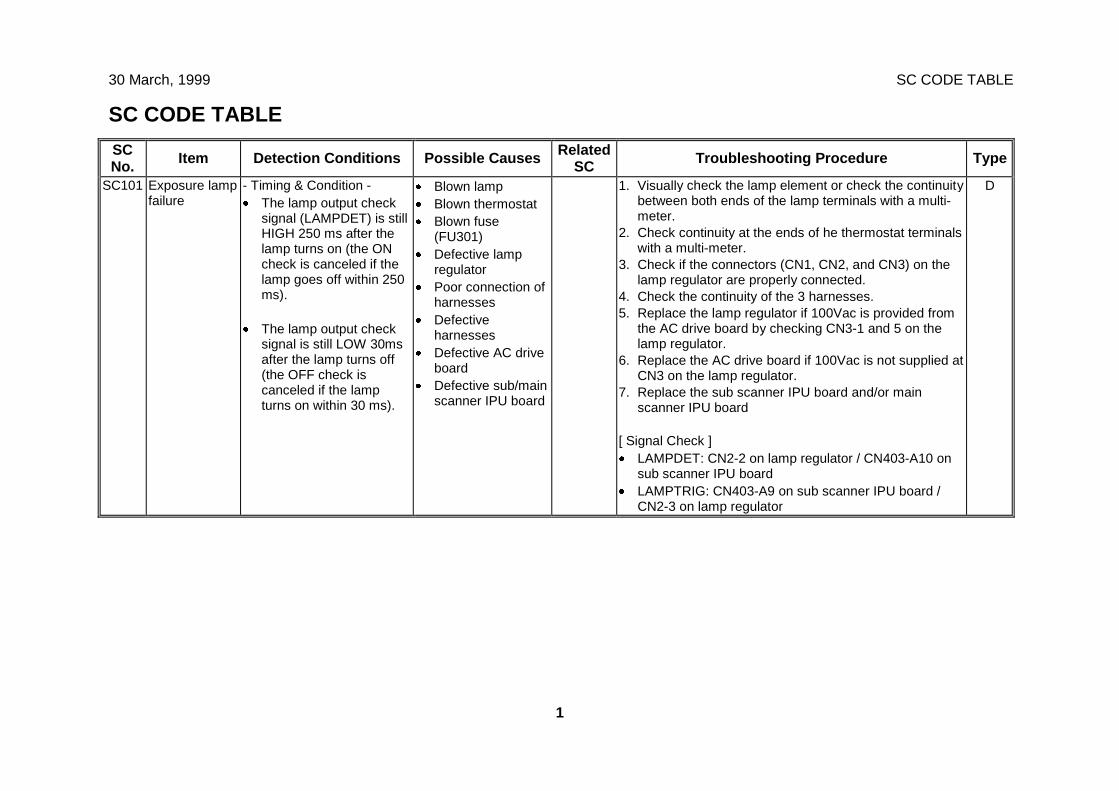
30 March, 1999 SC CODE TABLE
1
SC CODE TABLE
SCNo. Item Detection Conditions Possible Causes Related
SC Troubleshooting Procedure Type
SC101 Exposure lampfailure
- Timing & Condition -· The lamp output check
signal (LAMPDET) is stillHIGH 250 ms after thelamp turns on (the ONcheck is canceled if thelamp goes off within 250ms).
· The lamp output checksignal is still LOW 30msafter the lamp turns off(the OFF check iscanceled if the lampturns on within 30 ms).
· Blown lamp· Blown thermostat· Blown fuse
(FU301)· Defective lamp
regulator· Poor connection of
harnesses· Defective
harnesses· Defective AC drive
board· Defective sub/main
scanner IPU board
1. Visually check the lamp element or check the continuitybetween both ends of the lamp terminals with a multi-meter.
2. Check continuity at the ends of he thermostat terminalswith a multi-meter.
3. Check if the connectors (CN1, CN2, and CN3) on thelamp regulator are properly connected.
4. Check the continuity of the 3 harnesses.5. Replace the lamp regulator if 100Vac is provided from
the AC drive board by checking CN3-1 and 5 on thelamp regulator.
6. Replace the AC drive board if 100Vac is not supplied atCN3 on the lamp regulator.
7. Replace the sub scanner IPU board and/or mainscanner IPU board
[ Signal Check ]· LAMPDET: CN2-2 on lamp regulator / CN403-A10 on
sub scanner IPU board· LAMPTRIG: CN403-A9 on sub scanner IPU board /
CN2-3 on lamp regulator
D
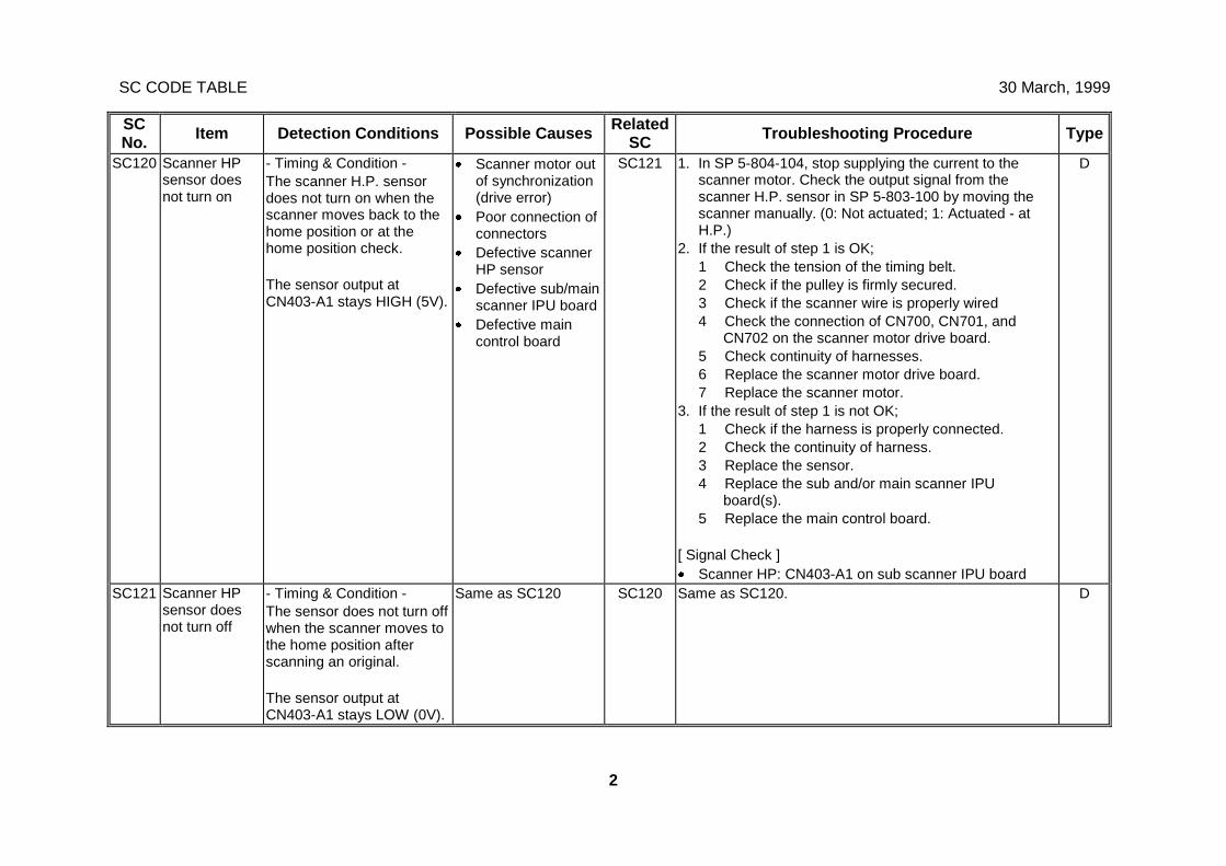
SC CODE TABLE 30 March, 1999
2
SCNo. Item Detection Conditions Possible Causes Related
SC Troubleshooting Procedure Type
SC120 Scanner HPsensor doesnot turn on
- Timing & Condition -The scanner H.P. sensordoes not turn on when thescanner moves back to thehome position or at thehome position check.
The sensor output atCN403-A1 stays HIGH (5V).
· Scanner motor outof synchronization(drive error)
· Poor connection ofconnectors
· Defective scannerHP sensor
· Defective sub/mainscanner IPU board
· Defective maincontrol board
SC121 1. In SP 5-804-104, stop supplying the current to thescanner motor. Check the output signal from thescanner H.P. sensor in SP 5-803-100 by moving thescanner manually. (0: Not actuated; 1: Actuated - atH.P.)
2. If the result of step 1 is OK;1 Check the tension of the timing belt.2 Check if the pulley is firmly secured.3 Check if the scanner wire is properly wired4 Check the connection of CN700, CN701, and
CN702 on the scanner motor drive board.5 Check continuity of harnesses.6 Replace the scanner motor drive board.7 Replace the scanner motor.
3. If the result of step 1 is not OK;1 Check if the harness is properly connected.2 Check the continuity of harness.3 Replace the sensor.4 Replace the sub and/or main scanner IPU
board(s).5 Replace the main control board.
[ Signal Check ]· Scanner HP: CN403-A1 on sub scanner IPU board
D
SC121 Scanner HPsensor doesnot turn off
- Timing & Condition -The sensor does not turn offwhen the scanner moves tothe home position afterscanning an original.
The sensor output atCN403-A1 stays LOW (0V).
Same as SC120 SC120 Same as SC120. D
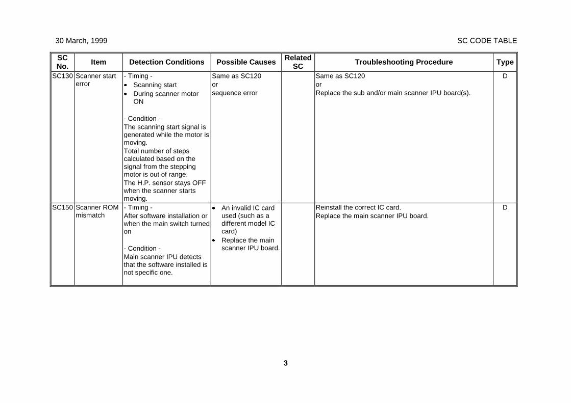
30 March, 1999 SC CODE TABLE
3
SCNo. Item Detection Conditions Possible Causes Related
SC Troubleshooting Procedure Type
SC130 Scanner starterror
- Timing -· Scanning start· During scanner motor
ON
- Condition -The scanning start signal isgenerated while the motor ismoving.Total number of stepscalculated based on thesignal from the steppingmotor is out of range.The H.P. sensor stays OFFwhen the scanner startsmoving.
Same as SC120orsequence error
Same as SC120orReplace the sub and/or main scanner IPU board(s).
D
SC150 Scanner ROMmismatch
- Timing -After software installation orwhen the main switch turnedon
- Condition -Main scanner IPU detectsthat the software installed isnot specific one.
· An invalid IC cardused (such as adifferent model ICcard)
· Replace the mainscanner IPU board.
Reinstall the correct IC card.Replace the main scanner IPU board.
D
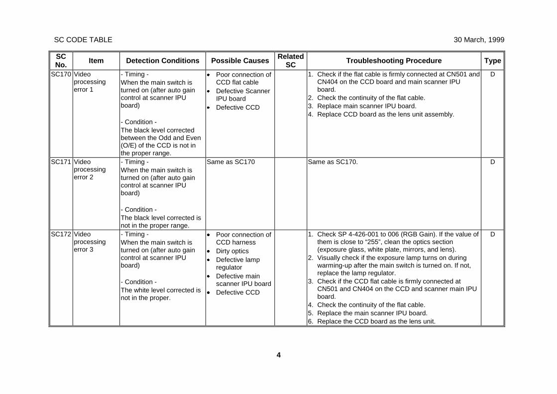
SC CODE TABLE 30 March, 1999
4
SCNo. Item Detection Conditions Possible Causes Related
SC Troubleshooting Procedure Type
SC170 Videoprocessingerror 1
- Timing -When the main switch isturned on (after auto gaincontrol at scanner IPUboard)
- Condition -The black level correctedbetween the Odd and Even(O/E) of the CCD is not inthe proper range.
· Poor connection ofCCD flat cable
· Defective ScannerIPU board
· Defective CCD
1. Check if the flat cable is firmly connected at CN501 andCN404 on the CCD board and main scanner IPUboard.
2. Check the continuity of the flat cable.3. Replace main scanner IPU board.4. Replace CCD board as the lens unit assembly.
D
SC171 Videoprocessingerror 2
- Timing -When the main switch isturned on (after auto gaincontrol at scanner IPUboard)
- Condition -The black level corrected isnot in the proper range.
Same as SC170 Same as SC170. D
SC172 Videoprocessingerror 3
- Timing -When the main switch isturned on (after auto gaincontrol at scanner IPUboard)
- Condition -The white level corrected isnot in the proper.
· Poor connection ofCCD harness
· Dirty optics· Defective lamp
regulator· Defective main
scanner IPU board· Defective CCD
1. Check SP 4-426-001 to 006 (RGB Gain). If the value ofthem is close to “255”, clean the optics section(exposure glass, white plate, mirrors, and lens).
2. Visually check if the exposure lamp turns on duringwarming-up after the main switch is turned on. If not,replace the lamp regulator.
3. Check if the CCD flat cable is firmly connected atCN501 and CN404 on the CCD and scanner main IPUboard.
4. Check the continuity of the flat cable.5. Replace the main scanner IPU board.6. Replace the CCD board as the lens unit.
D
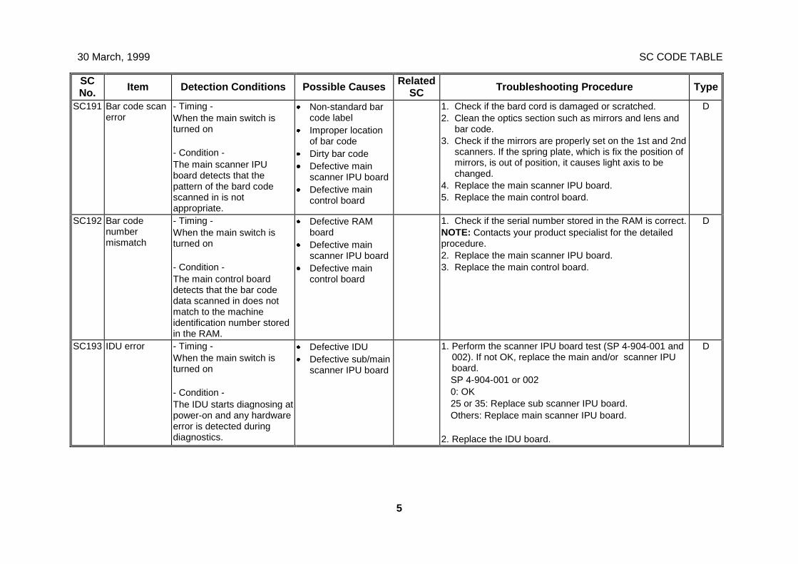
30 March, 1999 SC CODE TABLE
5
SCNo. Item Detection Conditions Possible Causes Related
SC Troubleshooting Procedure Type
SC191 Bar code scanerror
- Timing -When the main switch isturned on
- Condition -The main scanner IPUboard detects that thepattern of the bard codescanned in is notappropriate.
· Non-standard barcode label
· Improper locationof bar code
· Dirty bar code· Defective main
scanner IPU board· Defective main
control board
1. Check if the bard cord is damaged or scratched.2. Clean the optics section such as mirrors and lens and
bar code.3. Check if the mirrors are properly set on the 1st and 2nd
scanners. If the spring plate, which is fix the position ofmirrors, is out of position, it causes light axis to bechanged.
4. Replace the main scanner IPU board.5. Replace the main control board.
D
SC192 Bar codenumbermismatch
- Timing -When the main switch isturned on
- Condition -The main control boarddetects that the bar codedata scanned in does notmatch to the machineidentification number storedin the RAM.
· Defective RAMboard
· Defective mainscanner IPU board
· Defective maincontrol board
1. Check if the serial number stored in the RAM is correct.NOTE: Contacts your product specialist for the detailedprocedure.2. Replace the main scanner IPU board.3. Replace the main control board.
D
SC193 IDU error - Timing -When the main switch isturned on
- Condition -The IDU starts diagnosing atpower-on and any hardwareerror is detected duringdiagnostics.
· Defective IDU· Defective sub/main
scanner IPU board
1. Perform the scanner IPU board test (SP 4-904-001 and002). If not OK, replace the main and/or scanner IPUboard.SP 4-904-001 or 0020: OK25 or 35: Replace sub scanner IPU board.Others: Replace main scanner IPU board.
2. Replace the IDU board.
D
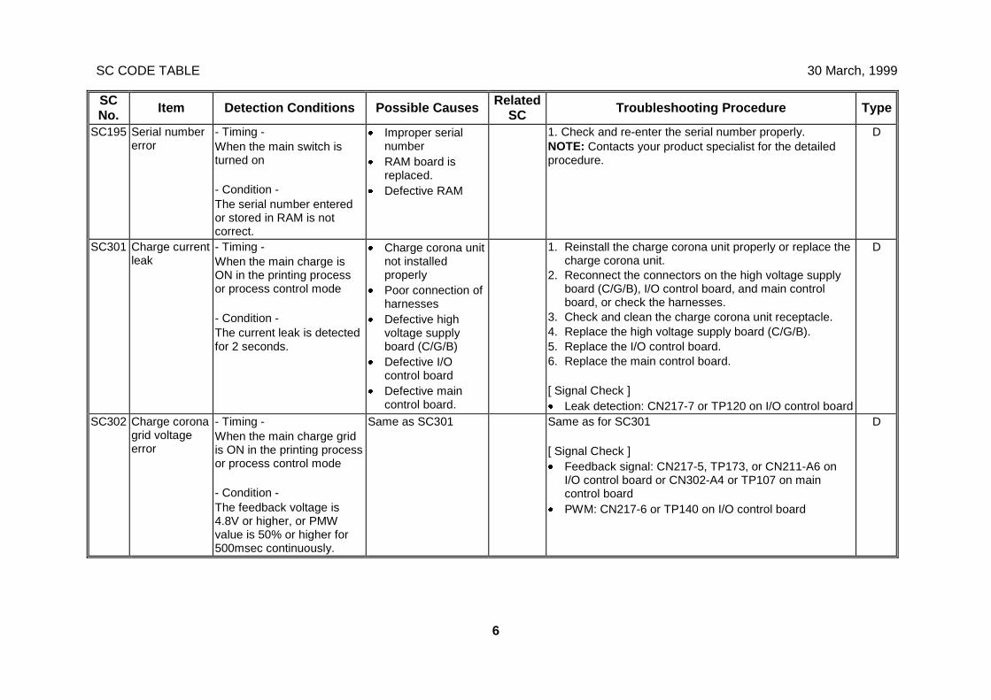
SC CODE TABLE 30 March, 1999
6
SCNo. Item Detection Conditions Possible Causes Related
SC Troubleshooting Procedure Type
SC195 Serial numbererror
- Timing -When the main switch isturned on
- Condition -The serial number enteredor stored in RAM is notcorrect.
· Improper serialnumber
· RAM board isreplaced.
· Defective RAM
1. Check and re-enter the serial number properly.NOTE: Contacts your product specialist for the detailedprocedure.
D
SC301 Charge currentleak
- Timing -When the main charge isON in the printing processor process control mode
- Condition -The current leak is detectedfor 2 seconds.
· Charge corona unitnot installedproperly
· Poor connection ofharnesses
· Defective highvoltage supplyboard (C/G/B)
· Defective I/Ocontrol board
· Defective maincontrol board.
1. Reinstall the charge corona unit properly or replace thecharge corona unit.
2. Reconnect the connectors on the high voltage supplyboard (C/G/B), I/O control board, and main controlboard, or check the harnesses.
3. Check and clean the charge corona unit receptacle.4. Replace the high voltage supply board (C/G/B).5. Replace the I/O control board.6. Replace the main control board.
[ Signal Check ]· Leak detection: CN217-7 or TP120 on I/O control board
D
SC302 Charge coronagrid voltageerror
- Timing -When the main charge gridis ON in the printing processor process control mode
- Condition -The feedback voltage is4.8V or higher, or PMWvalue is 50% or higher for500msec continuously.
Same as SC301 Same as for SC301
[ Signal Check ]· Feedback signal: CN217-5, TP173, or CN211-A6 on
I/O control board or CN302-A4 or TP107 on maincontrol board
· PWM: CN217-6 or TP140 on I/O control board
D
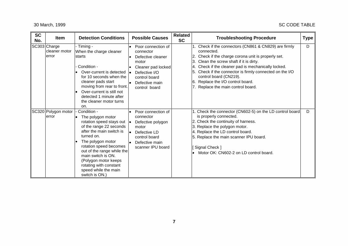
30 March, 1999 SC CODE TABLE
7
SCNo. Item Detection Conditions Possible Causes Related
SC Troubleshooting Procedure Type
SC303 Chargecleaner motorerror
- Timing -When the charge cleanerstarts
- Condition -· Over-current is detected
for 10 seconds when thecleaner pads startmoving from rear to front.
· Over-current is still notdetected 1 minute afterthe cleaner motor turnson.
· Poor connection ofconnector
· Defective cleanermotor
· Cleaner pad locked· Defective I/O
control board· Defective main
control board
1. Check if the connectors (CN861 & CN829) are firmlyconnected.
2. Check if the charge corona unit is properly set.3. Clean the screw shaft if it is dirty.4. Check if the cleaner pad is mechanically locked.5. Check if the connector is firmly connected on the I/O
control board (CN219).6. Replace the I/O control board.7. Replace the main control board.
D
SC320 Polygon motorerror
- Condition -· The polygon motor
rotation speed stays outof the range 22 secondsafter the main switch isturned on.
· The polygon motorrotation speed becomesout of the range while themain switch is ON.(Polygon motor keepsrotating with constantspeed while the mainswitch is ON.)
· Poor connection ofconnector
· Defective polygonmotor
· Defective LDcontrol board
· Defective mainscanner IPU board
1. Check the connector (CN602-5) on the LD control boardis properly connected.
2. Check the continuity of harness.3. Replace the polygon motor.4. Replace the LD control board.5. Replace the main scanner IPU board.
[ Signal Check ]· Motor OK: CN602-2 on LD control board.
D
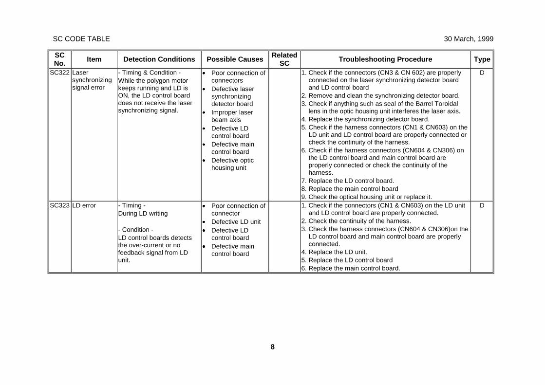
SC CODE TABLE 30 March, 1999
8
SCNo. Item Detection Conditions Possible Causes Related
SC Troubleshooting Procedure Type
SC322 Lasersynchronizingsignal error
- Timing & Condition -While the polygon motorkeeps running and LD isON, the LD control boarddoes not receive the lasersynchronizing signal.
· Poor connection ofconnectors
· Defective lasersynchronizingdetector board
· Improper laserbeam axis
· Defective LDcontrol board
· Defective maincontrol board
· Defective optichousing unit
1. Check if the connectors (CN3 & CN 602) are properlyconnected on the laser synchronizing detector boardand LD control board
2. Remove and clean the synchronizing detector board.3. Check if anything such as seal of the Barrel Toroidal
lens in the optic housing unit interferes the laser axis.4. Replace the synchronizing detector board.5. Check if the harness connectors (CN1 & CN603) on the
LD unit and LD control board are properly connected orcheck the continuity of the harness.
6. Check if the harness connectors (CN604 & CN306) onthe LD control board and main control board areproperly connected or check the continuity of theharness.
7. Replace the LD control board.8. Replace the main control board9. Check the optical housing unit or replace it.
D
SC323 LD error - Timing -During LD writing
- Condition -LD control boards detectsthe over-current or nofeedback signal from LDunit.
· Poor connection ofconnector
· Defective LD unit· Defective LD
control board· Defective main
control board
1. Check if the connectors (CN1 & CN603) on the LD unitand LD control board are properly connected.
2. Check the continuity of the harness.3. Check the harness connectors (CN604 & CN306)on the
LD control board and main control board are properlyconnected.
4. Replace the LD unit.5. Replace the LD control board6. Replace the main control board.
D
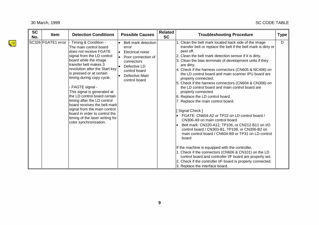
30 March, 1999 SC CODE TABLE
9
SCNo. Item Detection Conditions Possible Causes Related
SC Troubleshooting Procedure Type
SC326 FGATE1 error - Timing & Condition -The main control boarddoes not receive FGATEsignal from the LD controlboard while the imagetransfer belt makes 3revolution after the Start keyis pressed or at certaintiming during copy cycle.
- FAGTE signal -This signal is generated atthe LD control board certaintiming after the LD controlboard receives the belt marksignal from the main controlboard in order to control thetiming of the laser writing forcolor synchronization.
· Belt mark detectionerror
· Electrical noise· Poor connection of
connectors· Defective LD
control board· Defective Main
control board
1. Clean the belt mark located back side of the imagetransfer belt or replace the belt if the belt mark is dirty orpeel off.
2. Clean the belt mark detection sensor if it is dirty.3. Clean the bias terminals of development units if they
are dirty.4. Check if the harness connectors (CN605 & NC406) on
the LD control board and main scanner IPU board areproperly connected.
5. Check if the harness connectors (CN604 & CN306) onthe LD control board and main control board areproperly connected.
6. Replace the LD control board.7. Replace the main control board.
[ Signal Check ]· FGATE: CN604-A2 or TP22 on LD control board /
CN306-A9 on main control board· Belt mark: CN220-A12, TP106, or CN212-B11 on I/O
control board / CN303-B1, TP108, or CN306-B2 onmain control board / CN604-B9 or TP31 on LD controlboard
If the machine is equipped with the controller,1. Check if the connectors (CN606 & CN101) on the LD
control board and controller I/F board are properly set.2. Check if the controller I/F board is properly connected.3. Replace the interface board.
D
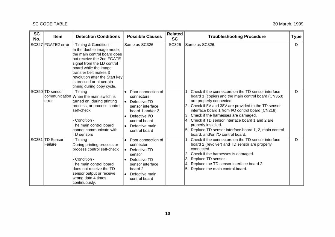
SC CODE TABLE 30 March, 1999
10
SCNo. Item Detection Conditions Possible Causes Related
SC Troubleshooting Procedure Type
SC327 FGATE2 error - Timing & Condition -In the double image mode,the main control board doesnot receive the 2nd FGATEsignal from the LD controlboard while the imagetransfer belt makes 3revolution after the Start keyis pressed or at certaintiming during copy cycle.
Same as SC326 SC326 Same as SC326. D
SC350 TD sensorcommunicationerror
- Timing -When the main switch isturned on, during printingprocess, or process controlself-check
- Condition -The main control boardcannot communicate withTD sensors
· Poor connection ofconnectors
· Defective TDsensor interfaceboard 1 and/or 2
· Defective I/Ocontrol board
· Defective maincontrol board
1. Check if the connectors on the TD sensor interfaceboard 1 (copier) and the main control board (CN353)are properly connected.
2. Check if 5V and 38V are provided to the TD sensorinterface board 1 from I/O control board (CN218).
3. Check if the harnesses are damaged.4. Check if TD sensor interface board 1 and 2 are
properly installed.5. Replace TD sensor interface board 1, 2, main control
board, and/or I/O control board.
D
SC351 TD SensorFailure
- Timing -During printing process orprocess control self-check
- Condition -The main control boarddoes not receive the TDsensor output or receivewrong data 4 timescontinuously.
· Poor connection ofconnector
· Defective TDsensor
· Defective TDsensor interfaceboard 2
· Defective maincontrol board
1. Check if the connectors on the TD sensor interfaceboard 2 (revolver) and TD sensor are properlyconnected.
2. Check if the harnesses is damaged.3. Replace TD sensor.4. Replace the TD sensor interface board 2.5. Replace the main control board.
D
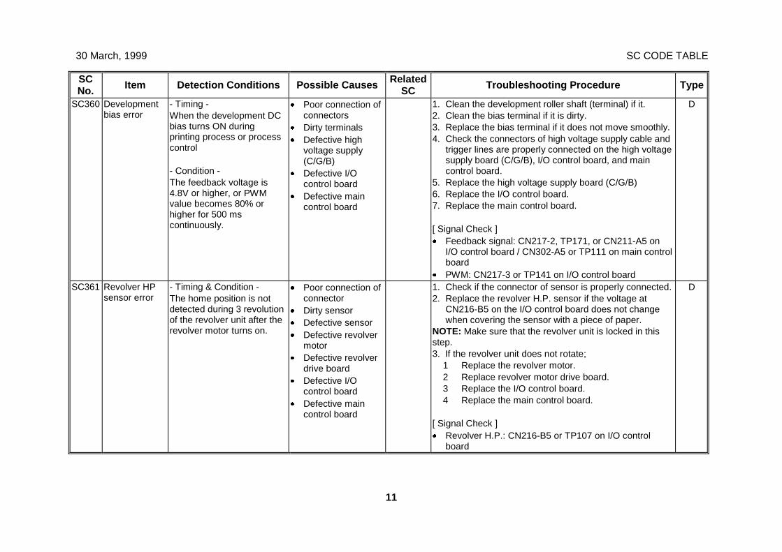
30 March, 1999 SC CODE TABLE
11
SCNo. Item Detection Conditions Possible Causes Related
SC Troubleshooting Procedure Type
SC360 Developmentbias error
- Timing -When the development DCbias turns ON duringprinting process or processcontrol
- Condition -The feedback voltage is4.8V or higher, or PWMvalue becomes 80% orhigher for 500 mscontinuously.
· Poor connection ofconnectors
· Dirty terminals· Defective high
voltage supply(C/G/B)
· Defective I/Ocontrol board
· Defective maincontrol board
1. Clean the development roller shaft (terminal) if it.2. Clean the bias terminal if it is dirty.3. Replace the bias terminal if it does not move smoothly.4. Check the connectors of high voltage supply cable and
trigger lines are properly connected on the high voltagesupply board (C/G/B), I/O control board, and maincontrol board.
5. Replace the high voltage supply board (C/G/B)6. Replace the I/O control board.7. Replace the main control board.
[ Signal Check ]· Feedback signal: CN217-2, TP171, or CN211-A5 on
I/O control board / CN302-A5 or TP111 on main controlboard
· PWM: CN217-3 or TP141 on I/O control board
D
SC361 Revolver HPsensor error
- Timing & Condition -The home position is notdetected during 3 revolutionof the revolver unit after therevolver motor turns on.
· Poor connection ofconnector
· Dirty sensor· Defective sensor· Defective revolver
motor· Defective revolver
drive board· Defective I/O
control board· Defective main
control board
1. Check if the connector of sensor is properly connected.2. Replace the revolver H.P. sensor if the voltage at
CN216-B5 on the I/O control board does not changewhen covering the sensor with a piece of paper.
NOTE: Make sure that the revolver unit is locked in thisstep.3. If the revolver unit does not rotate;
1 Replace the revolver motor.2 Replace revolver motor drive board.3 Replace the I/O control board.4 Replace the main control board.
[ Signal Check ]· Revolver H.P.: CN216-B5 or TP107 on I/O control
board
D
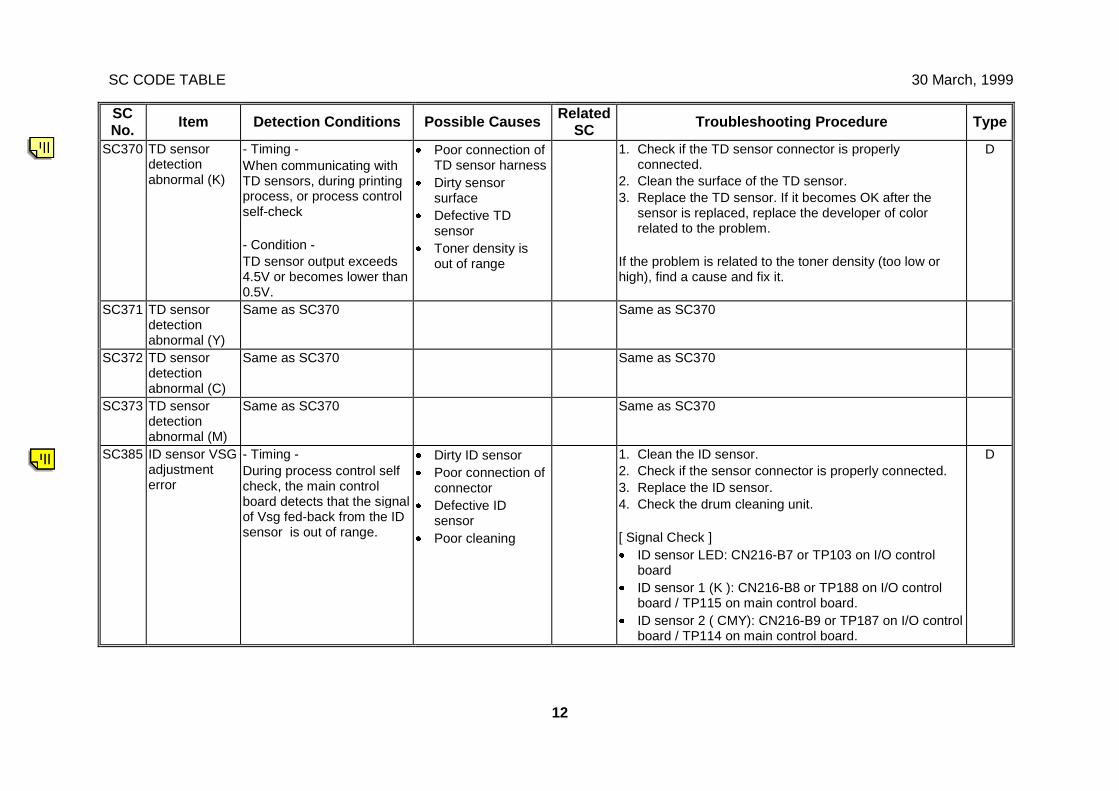
SC CODE TABLE 30 March, 1999
12
SCNo. Item Detection Conditions Possible Causes Related
SC Troubleshooting Procedure Type
SC370 TD sensordetectionabnormal (K)
- Timing -When communicating withTD sensors, during printingprocess, or process controlself-check
- Condition -TD sensor output exceeds4.5V or becomes lower than0.5V.
· Poor connection ofTD sensor harness
· Dirty sensorsurface
· Defective TDsensor
· Toner density isout of range
1. Check if the TD sensor connector is properlyconnected.
2. Clean the surface of the TD sensor.3. Replace the TD sensor. If it becomes OK after the
sensor is replaced, replace the developer of colorrelated to the problem.
If the problem is related to the toner density (too low orhigh), find a cause and fix it.
D
SC371 TD sensordetectionabnormal (Y)
Same as SC370 Same as SC370
SC372 TD sensordetectionabnormal (C)
Same as SC370 Same as SC370
SC373 TD sensordetectionabnormal (M)
Same as SC370 Same as SC370
SC385 ID sensor VSGadjustmenterror
- Timing -During process control selfcheck, the main controlboard detects that the signalof Vsg fed-back from the IDsensor is out of range.
· Dirty ID sensor· Poor connection of
connector· Defective ID
sensor· Poor cleaning
1. Clean the ID sensor.2. Check if the sensor connector is properly connected.3. Replace the ID sensor.4. Check the drum cleaning unit.
[ Signal Check ]· ID sensor LED: CN216-B7 or TP103 on I/O control
board· ID sensor 1 (K ): CN216-B8 or TP188 on I/O control
board / TP115 on main control board.· ID sensor 2 ( CMY): CN216-B9 or TP187 on I/O control
board / TP114 on main control board.
D
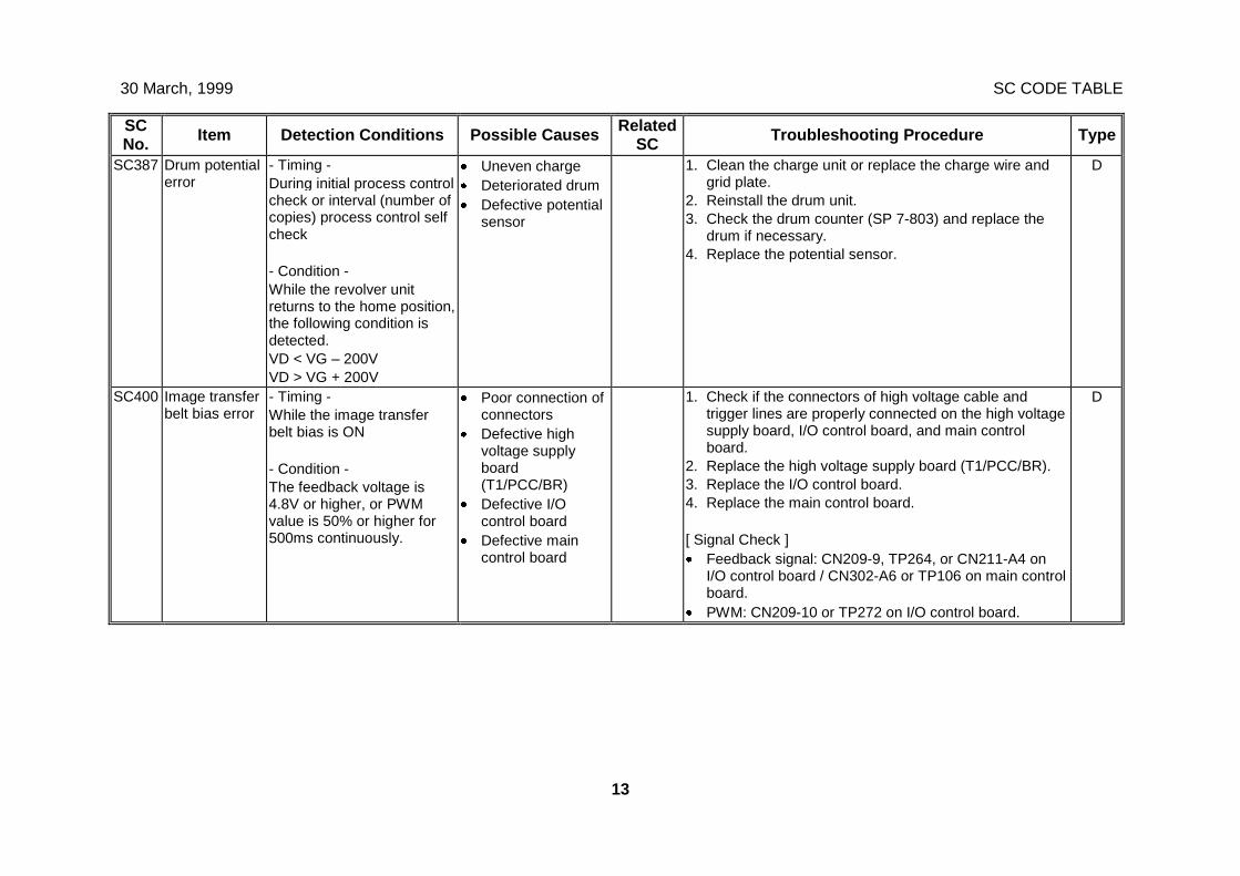
30 March, 1999 SC CODE TABLE
13
SCNo. Item Detection Conditions Possible Causes Related
SC Troubleshooting Procedure Type
SC387 Drum potentialerror
- Timing -During initial process controlcheck or interval (number ofcopies) process control selfcheck
- Condition -While the revolver unitreturns to the home position,the following condition isdetected.VD < VG – 200VVD > VG + 200V
· Uneven charge· Deteriorated drum· Defective potential
sensor
1. Clean the charge unit or replace the charge wire andgrid plate.
2. Reinstall the drum unit.3. Check the drum counter (SP 7-803) and replace the
drum if necessary.4. Replace the potential sensor.
D
SC400 Image transferbelt bias error
- Timing -While the image transferbelt bias is ON
- Condition -The feedback voltage is4.8V or higher, or PWMvalue is 50% or higher for500ms continuously.
· Poor connection ofconnectors
· Defective highvoltage supplyboard(T1/PCC/BR)
· Defective I/Ocontrol board
· Defective maincontrol board
1. Check if the connectors of high voltage cable andtrigger lines are properly connected on the high voltagesupply board, I/O control board, and main controlboard.
2. Replace the high voltage supply board (T1/PCC/BR).3. Replace the I/O control board.4. Replace the main control board.
[ Signal Check ]· Feedback signal: CN209-9, TP264, or CN211-A4 on
I/O control board / CN302-A6 or TP106 on main controlboard.
· PWM: CN209-10 or TP272 on I/O control board.
D
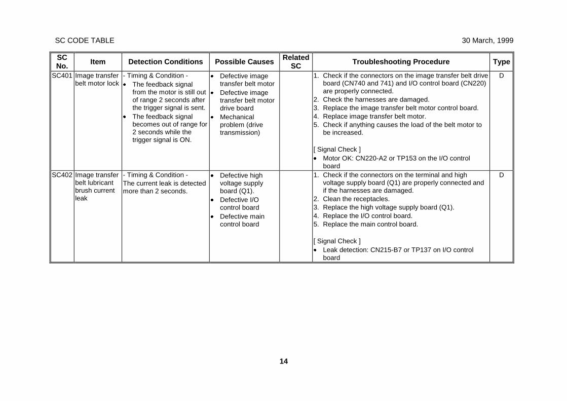
SC CODE TABLE 30 March, 1999
14
SCNo. Item Detection Conditions Possible Causes Related
SC Troubleshooting Procedure Type
SC401 Image transferbelt motor lock
- Timing & Condition -· The feedback signal
from the motor is still outof range 2 seconds afterthe trigger signal is sent.
· The feedback signalbecomes out of range for2 seconds while thetrigger signal is ON.
· Defective imagetransfer belt motor
· Defective imagetransfer belt motordrive board
· Mechanicalproblem (drivetransmission)
1. Check if the connectors on the image transfer belt driveboard (CN740 and 741) and I/O control board (CN220)are properly connected.
2. Check the harnesses are damaged.3. Replace the image transfer belt motor control board.4. Replace image transfer belt motor.5. Check if anything causes the load of the belt motor to
be increased.
[ Signal Check ]· Motor OK: CN220-A2 or TP153 on the I/O control
board
D
SC402 Image transferbelt lubricantbrush currentleak
- Timing & Condition -The current leak is detectedmore than 2 seconds.
· Defective highvoltage supplyboard (Q1).
· Defective I/Ocontrol board
· Defective maincontrol board
1. Check if the connectors on the terminal and highvoltage supply board (Q1) are properly connected andif the harnesses are damaged.
2. Clean the receptacles.3. Replace the high voltage supply board (Q1).4. Replace the I/O control board.5. Replace the main control board.
[ Signal Check ]· Leak detection: CN215-B7 or TP137 on I/O control
board
D
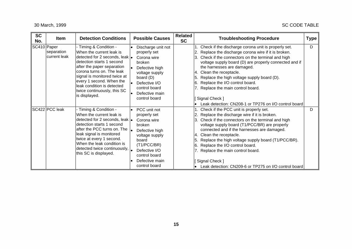
30 March, 1999 SC CODE TABLE
15
SCNo. Item Detection Conditions Possible Causes Related
SC Troubleshooting Procedure Type
SC410 Paperseparationcurrent leak
- Timing & Condition -When the current leak isdetected for 2 seconds, leakdetection starts 1 secondafter the paper separationcorona turns on. The leaksignal is monitored twice atevery 1 second. When theleak condition is detectedtwice continuously, this SCis displayed.
· Discharge unit notproperly set
· Corona wirebroken
· Defective highvoltage supplyboard (D)
· Defective I/Ocontrol board
· Defective maincontrol board
1. Check if the discharge corona unit is properly set.2. Replace the discharge corona wire if it is broken.3. Check if the connectors on the terminal and high
voltage supply board (D) are properly connected and ifthe harnesses are damaged.
4. Clean the receptacle.5. Replace the high voltage supply board (D).6. Replace the I/O control board.7. Replace the main control board.
[ Signal Check ]· Leak detection: CN208-1 or TP276 on I/O control board
D
SC422 PCC leak - Timing & Condition -When the current leak isdetected for 2 seconds, leakdetection starts 1 secondafter the PCC turns on. Theleak signal is monitoredtwice at every 1 second.When the leak condition isdetected twice continuously,this SC is displayed.
· PCC unit notproperly set
· Corona wirebroken
· Defective highvoltage supplyboard(T1/PCC/BR)
· Defective I/Ocontrol board
· Defective maincontrol board
1. Check if the PCC unit is properly set.2. Replace the discharge wire if it is broken.3. Check if the connectors on the terminal and high
voltage supply board (T1/PCC/BR) are properlyconnected and if the harnesses are damaged.
4. Clean the receptacle.5. Replace the high voltage supply board (T1/PCC/BR).6. Replace the I/O control board.7. Replace the main control board.
[ Signal Check ]· Leak detection: CN209-6 or TP275 on I/O control board
D
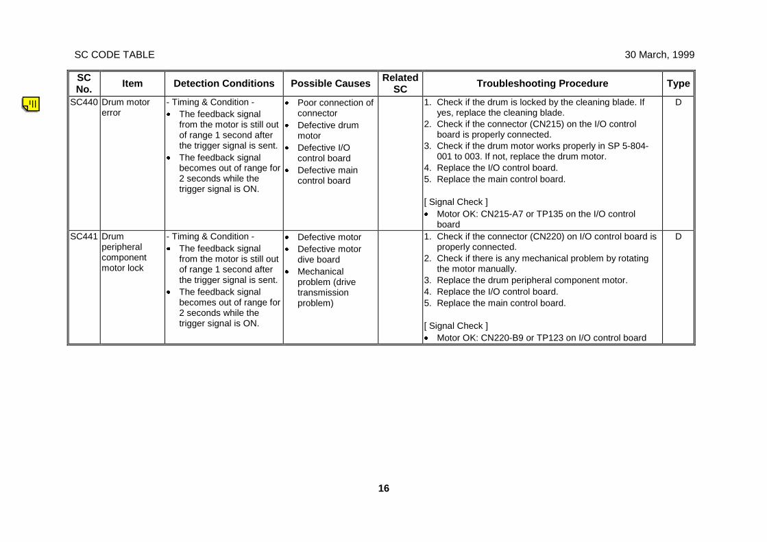
SC CODE TABLE 30 March, 1999
16
SCNo. Item Detection Conditions Possible Causes Related
SC Troubleshooting Procedure Type
SC440 Drum motorerror
- Timing & Condition -· The feedback signal
from the motor is still outof range 1 second afterthe trigger signal is sent.
· The feedback signalbecomes out of range for2 seconds while thetrigger signal is ON.
· Poor connection ofconnector
· Defective drummotor
· Defective I/Ocontrol board
· Defective maincontrol board
1. Check if the drum is locked by the cleaning blade. Ifyes, replace the cleaning blade.
2. Check if the connector (CN215) on the I/O controlboard is properly connected.
3. Check if the drum motor works properly in SP 5-804-001 to 003. If not, replace the drum motor.
4. Replace the I/O control board.5. Replace the main control board.
[ Signal Check ]· Motor OK: CN215-A7 or TP135 on the I/O control
board
D
SC441 Drumperipheralcomponentmotor lock
- Timing & Condition -· The feedback signal
from the motor is still outof range 1 second afterthe trigger signal is sent.
· The feedback signalbecomes out of range for2 seconds while thetrigger signal is ON.
· Defective motor· Defective motor
dive board· Mechanical
problem (drivetransmissionproblem)
1. Check if the connector (CN220) on I/O control board isproperly connected.
2. Check if there is any mechanical problem by rotatingthe motor manually.
3. Replace the drum peripheral component motor.4. Replace the I/O control board.5. Replace the main control board.
[ Signal Check ]· Motor OK: CN220-B9 or TP123 on I/O control board
D
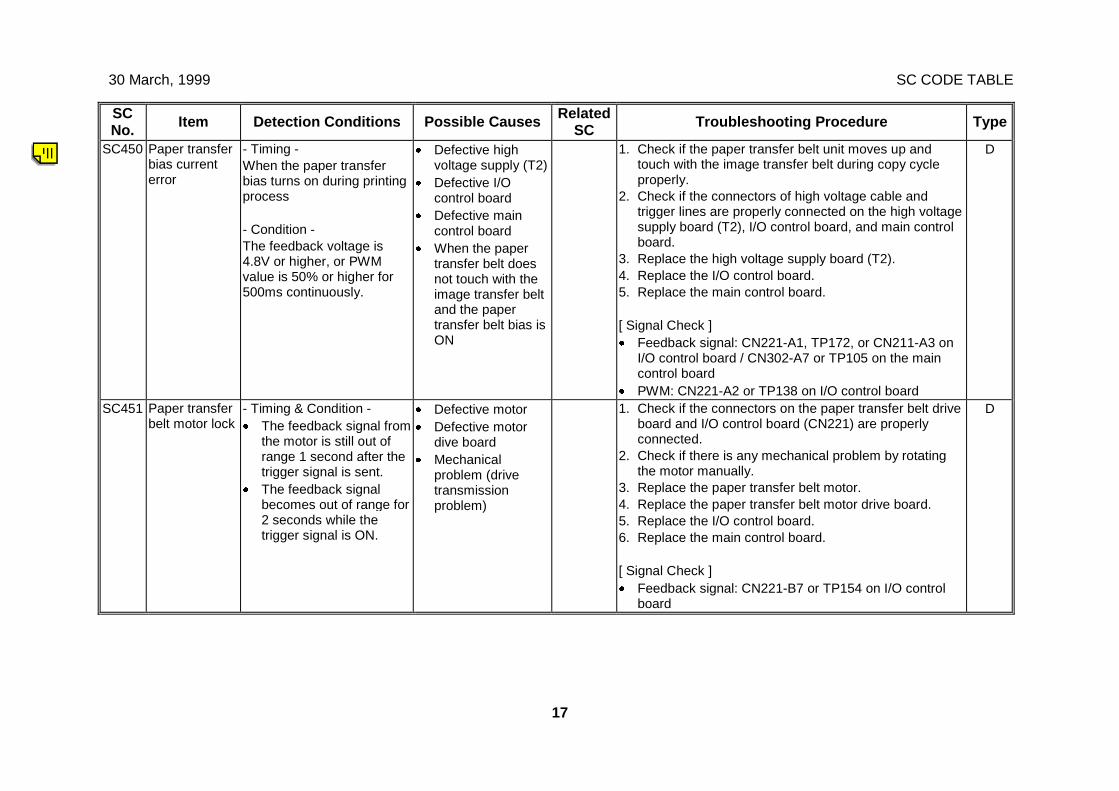
30 March, 1999 SC CODE TABLE
17
SCNo. Item Detection Conditions Possible Causes Related
SC Troubleshooting Procedure Type
SC450 Paper transferbias currenterror
- Timing -When the paper transferbias turns on during printingprocess
- Condition -The feedback voltage is4.8V or higher, or PWMvalue is 50% or higher for500ms continuously.
· Defective highvoltage supply (T2)
· Defective I/Ocontrol board
· Defective maincontrol board
· When the papertransfer belt doesnot touch with theimage transfer beltand the papertransfer belt bias isON
1. Check if the paper transfer belt unit moves up andtouch with the image transfer belt during copy cycleproperly.
2. Check if the connectors of high voltage cable andtrigger lines are properly connected on the high voltagesupply board (T2), I/O control board, and main controlboard.
3. Replace the high voltage supply board (T2).4. Replace the I/O control board.5. Replace the main control board.
[ Signal Check ]· Feedback signal: CN221-A1, TP172, or CN211-A3 on
I/O control board / CN302-A7 or TP105 on the maincontrol board
· PWM: CN221-A2 or TP138 on I/O control board
D
SC451 Paper transferbelt motor lock
- Timing & Condition -· The feedback signal from
the motor is still out ofrange 1 second after thetrigger signal is sent.
· The feedback signalbecomes out of range for2 seconds while thetrigger signal is ON.
· Defective motor· Defective motor
dive board· Mechanical
problem (drivetransmissionproblem)
1. Check if the connectors on the paper transfer belt driveboard and I/O control board (CN221) are properlyconnected.
2. Check if there is any mechanical problem by rotatingthe motor manually.
3. Replace the paper transfer belt motor.4. Replace the paper transfer belt motor drive board.5. Replace the I/O control board.6. Replace the main control board.
[ Signal Check ]· Feedback signal: CN221-B7 or TP154 on I/O control
board
D
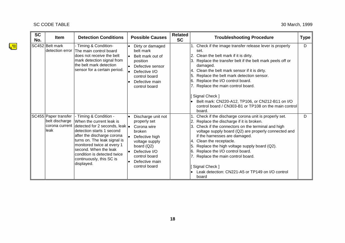
SC CODE TABLE 30 March, 1999
18
SCNo. Item Detection Conditions Possible Causes Related
SC Troubleshooting Procedure Type
SC452 Belt markdetection error
- Timing & Condition-The main control boarddoes not receive the beltmark detection signal fromthe belt mark detectionsensor for a certain period.
· Dirty or damagedbelt mark
· Belt mark out ofposition
· Defective sensor· Defective I/O
control board· Defective main
control board
1. Check if the image transfer release lever is properlyset.
2. Clean the belt mark if it is dirty.3. Replace the transfer belt if the belt mark peels off or
damaged.4. Clean the belt mark sensor if it is dirty.5. Replace the belt mark detection sensor.6. Replace the I/O control board.7. Replace the main control board.
[ Signal Check ]· Belt mark: CN220-A12, TP106, or CN212-B11 on I/O
control board / CN303-B1 or TP108 on the main controlboard.
D
SC455 Paper transferbelt dischargecorona currentleak
- Timing & Condition -When the current leak isdetected for 2 seconds, leakdetection starts 1 secondafter the discharge coronaturns on. The leak signal ismonitored twice at every 1second. When the leakcondition is detected twicecontinuously, this SC isdisplayed.
· Discharge unit notproperly set
· Corona wirebroken
· Defective highvoltage supplyboard (Q2)
· Defective I/Ocontrol board
· Defective maincontrol board
1. Check if the discharge corona unit is properly set.2. Replace the discharge if it is broken.3. Check if the connectors on the terminal and high
voltage supply board (Q2) are properly connected andif the harnesses are damaged.
4. Clean the receptacle.5. Replace the high voltage supply board (Q2).6. Replace the I/O control board.7. Replace the main control board.
[ Signal Check ]· Leak detection: CN221-A5 or TP149 on I/O control
board
D
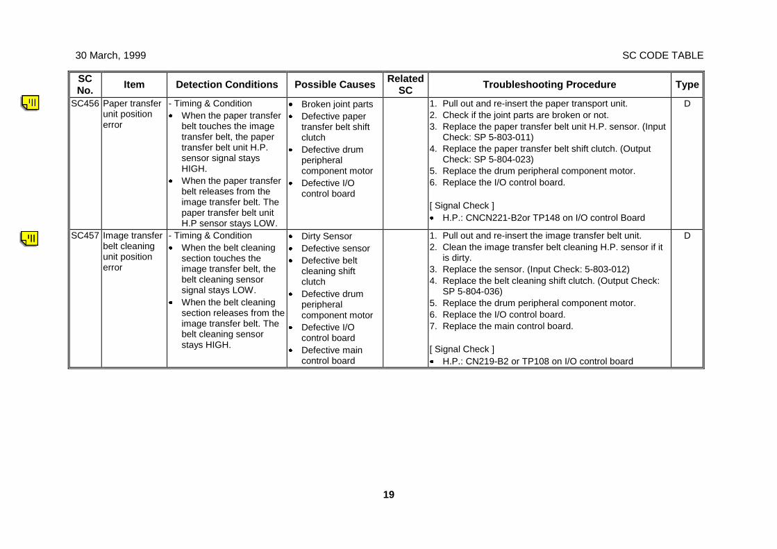
30 March, 1999 SC CODE TABLE
19
SCNo. Item Detection Conditions Possible Causes Related
SC Troubleshooting Procedure Type
SC456 Paper transferunit positionerror
- Timing & Condition· When the paper transfer
belt touches the imagetransfer belt, the papertransfer belt unit H.P.sensor signal staysHIGH.
· When the paper transferbelt releases from theimage transfer belt. Thepaper transfer belt unitH.P sensor stays LOW.
· Broken joint parts· Defective paper
transfer belt shiftclutch
· Defective drumperipheralcomponent motor
· Defective I/Ocontrol board
1. Pull out and re-insert the paper transport unit.2. Check if the joint parts are broken or not.3. Replace the paper transfer belt unit H.P. sensor. (Input
Check: SP 5-803-011)4. Replace the paper transfer belt shift clutch. (Output
Check: SP 5-804-023)5. Replace the drum peripheral component motor.6. Replace the I/O control board.
[ Signal Check ]· H.P.: CNCN221-B2or TP148 on I/O control Board
D
SC457 Image transferbelt cleaningunit positionerror
- Timing & Condition· When the belt cleaning
section touches theimage transfer belt, thebelt cleaning sensorsignal stays LOW.
· When the belt cleaningsection releases from theimage transfer belt. Thebelt cleaning sensorstays HIGH.
· Dirty Sensor· Defective sensor· Defective belt
cleaning shiftclutch
· Defective drumperipheralcomponent motor
· Defective I/Ocontrol board
· Defective maincontrol board
1. Pull out and re-insert the image transfer belt unit.2. Clean the image transfer belt cleaning H.P. sensor if it
is dirty.3. Replace the sensor. (Input Check: 5-803-012)4. Replace the belt cleaning shift clutch. (Output Check:
SP 5-804-036)5. Replace the drum peripheral component motor.6. Replace the I/O control board.7. Replace the main control board.
[ Signal Check ]· H.P.: CN219-B2 or TP108 on I/O control board
D
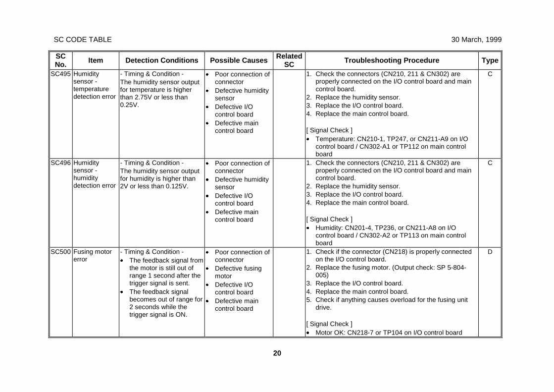
SC CODE TABLE 30 March, 1999
20
SCNo. Item Detection Conditions Possible Causes Related
SC Troubleshooting Procedure Type
SC495 Humiditysensor -temperaturedetection error
- Timing & Condition -The humidity sensor outputfor temperature is higherthan 2.75V or less than0.25V.
· Poor connection ofconnector
· Defective humiditysensor
· Defective I/Ocontrol board
· Defective maincontrol board
1. Check the connectors (CN210, 211 & CN302) areproperly connected on the I/O control board and maincontrol board.
2. Replace the humidity sensor.3. Replace the I/O control board.4. Replace the main control board.
[ Signal Check ]· Temperature: CN210-1, TP247, or CN211-A9 on I/O
control board / CN302-A1 or TP112 on main controlboard
C
SC496 Humiditysensor -humiditydetection error
- Timing & Condition -The humidity sensor outputfor humidity is higher than2V or less than 0.125V.
· Poor connection ofconnector
· Defective humiditysensor
· Defective I/Ocontrol board
· Defective maincontrol board
1. Check the connectors (CN210, 211 & CN302) areproperly connected on the I/O control board and maincontrol board.
2. Replace the humidity sensor.3. Replace the I/O control board.4. Replace the main control board.
[ Signal Check ]· Humidity: CN201-4, TP236, or CN211-A8 on I/O
control board / CN302-A2 or TP113 on main controlboard
C
SC500 Fusing motorerror
- Timing & Condition -· The feedback signal from
the motor is still out ofrange 1 second after thetrigger signal is sent.
· The feedback signalbecomes out of range for2 seconds while thetrigger signal is ON.
· Poor connection ofconnector
· Defective fusingmotor
· Defective I/Ocontrol board
· Defective maincontrol board
1. Check if the connector (CN218) is properly connectedon the I/O control board.
2. Replace the fusing motor. (Output check: SP 5-804-005)
3. Replace the I/O control board.4. Replace the main control board.5. Check if anything causes overload for the fusing unit
drive.
[ Signal Check ]· Motor OK: CN218-7 or TP104 on I/O control board
D

30 March, 1999 SC CODE TABLE
21
SCNo. Item Detection Conditions Possible Causes Related
SC Troubleshooting Procedure Type
SC501 1st paper trayerror
- Timing & Condition -· The upper limit sensor
stays HIGH when thepick-up solenoid turnsoff.
· The upper limit sensorstays LOW 1.5 secondsafter the tray bottomplate goes down.
· The upper limit sensorstays HIGH 10 secondsafter the tray bottomplate goes up.
· The upper limit sensorstays HIGH 3 secondsafter the tray bottomplate goes up again.
· Pick-up solenoidspring come off
· Defective upperlimit sensor
· Defective traybottom plate
· Defective tray liftmotor
· Defective I/Ocontrol board
· Defective maincontrol board
SC502SC503SC504
1. Check if the spring of pick-up solenoid comes off.2. Check if the sensor harness is properly connected.3. Clean or replace the sensor and replace it if necessary
(Input Check: SP 5-803-014 to 017).4. Replace the tray bottom lever if it is broken.5. Pull out the paper tray and check if the tray lift motor
works properly (Output Check: SP 5-804-75 to 82)6. Replace the I/O control board.7. Replace the main control board.
[ Signal Check ]· Limit sensor H.P.: CN224-A8 or TP215 on I/O control
board
B
SC502 2nd paper trayerror
Not used Not used B
SC503 3rd paper trayerror
Same as SC501 SC501SC502SC504
Same as SC501
[ Signal Check ]· Limit sensor H.P.: CN226-A8 or TP282 on I/O control
board
B
SC504 4th paper trayerror
Same as SC501 SC501SC502SC503
Same as SC501
[ Signal Check ]· Limit sensor H.P.: CN226-B8 or TP280 on I/O control
board
B
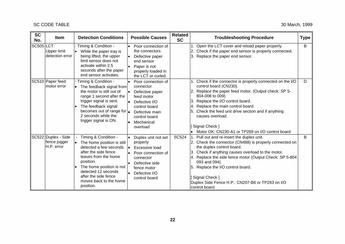
SC CODE TABLE 30 March, 1999
22
SCNo. Item Detection Conditions Possible Causes Related
SC Troubleshooting Procedure Type
SC505 LCT:Upper limitdetection error
- Timing & Condition -· While the paper tray is
being lifted, the upperlimit sensor does notactivate within 2.5seconds after the paperend sensor activates.
· Poor connection ofthe connectors
· Defective paperend sensor
· Paper is notproperly loaded inthe LCT or curled.
1. Open the LCT cover and reload paper properly.2. Check if the paper end sensor is properly connected.3. Replace the paper end sensor.
B
SC510 Paper feedmotor error
- Timing & Condition -· The feedback signal from
the motor is still out ofrange 1 second after thetrigger signal is sent.
· The feedback signalbecomes out of range for2 seconds while thetrigger signal is ON.
· Poor connection ofconnector
· Defective paperfeed motor
· Defective I/Ocontrol board
· Defective maincontrol board
· Mechanicaloverload
1. Check if the connector is properly connected on the I/Ocontrol board (CN230).
2. Replace the paper feed motor. (Output check: SP 5-804-008 to 009)
3. Replace the I/O control board.4. Replace the main control board.5. Check the feed unit drive section and if anything
causes overload.
[ Signal Check ]· Motor OK: CN230-A1 or TP269 on I/O control board
D
SC522 Duplex - Sidefence joggerH.P. error
- Timing & Condition -· The home position is still
detected a few secondsafter the side fenceleaves from the homeposition.
· The home position is notdetected 12 secondsafter the side fencemoves back to the homeposition.
· Duplex unit not setproperly
· Excessive load· Poor connection of
connector· Defective side
fence motor· Defective I/O
control board
SC524 1. Pull out and re-insert the duplex unit.2. Check the connector (CN488) is properly connected on
the duplex control board.3. Check if anything causes overload to the motor.4. Replace the side fence motor (Output Check: SP 5-804
093 and 094).5. Replace the I/O control board.
[ Signal Check ]Duplex Side Fence H.P.: CN207-B6 or TP293 on I/Ocontrol board
B
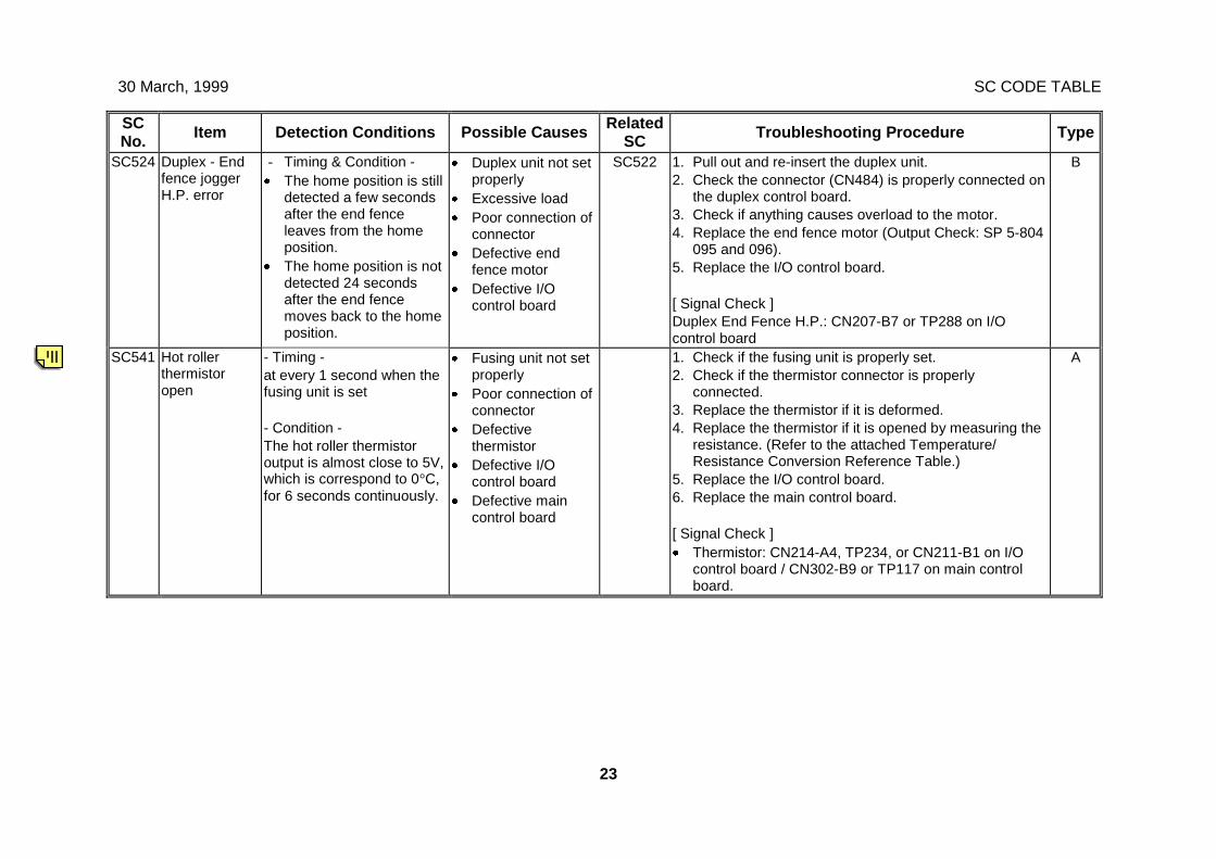
30 March, 1999 SC CODE TABLE
23
SCNo. Item Detection Conditions Possible Causes Related
SC Troubleshooting Procedure Type
SC524 Duplex - Endfence joggerH.P. error
- Timing & Condition -· The home position is still
detected a few secondsafter the end fenceleaves from the homeposition.
· The home position is notdetected 24 secondsafter the end fencemoves back to the homeposition.
· Duplex unit not setproperly
· Excessive load· Poor connection of
connector· Defective end
fence motor· Defective I/O
control board
SC522 1. Pull out and re-insert the duplex unit.2. Check the connector (CN484) is properly connected on
the duplex control board.3. Check if anything causes overload to the motor.4. Replace the end fence motor (Output Check: SP 5-804
095 and 096).5. Replace the I/O control board.
[ Signal Check ]Duplex End Fence H.P.: CN207-B7 or TP288 on I/Ocontrol board
B
SC541 Hot rollerthermistoropen
- Timing -at every 1 second when thefusing unit is set
- Condition -The hot roller thermistoroutput is almost close to 5V,which is correspond to 0°C,for 6 seconds continuously.
· Fusing unit not setproperly
· Poor connection ofconnector
· Defectivethermistor
· Defective I/Ocontrol board
· Defective maincontrol board
1. Check if the fusing unit is properly set.2. Check if the thermistor connector is properly
connected.3. Replace the thermistor if it is deformed.4. Replace the thermistor if it is opened by measuring the
resistance. (Refer to the attached Temperature/Resistance Conversion Reference Table.)
5. Replace the I/O control board.6. Replace the main control board.
[ Signal Check ]· Thermistor: CN214-A4, TP234, or CN211-B1 on I/O
control board / CN302-B9 or TP117 on main controlboard.
A
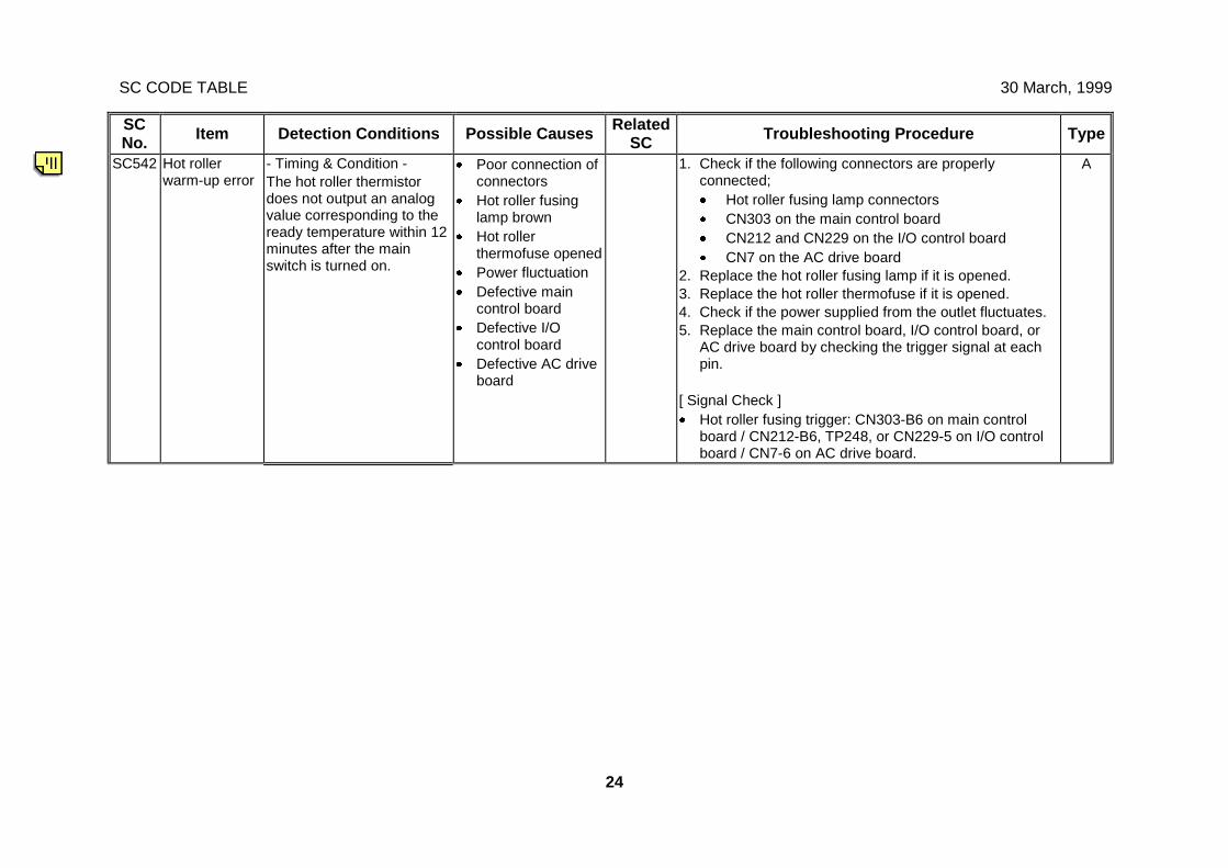
SC CODE TABLE 30 March, 1999
24
SCNo. Item Detection Conditions Possible Causes Related
SC Troubleshooting Procedure Type
SC542 Hot rollerwarm-up error
- Timing & Condition -The hot roller thermistordoes not output an analogvalue corresponding to theready temperature within 12minutes after the mainswitch is turned on.
· Poor connection ofconnectors
· Hot roller fusinglamp brown
· Hot rollerthermofuse opened
· Power fluctuation· Defective main
control board· Defective I/O
control board· Defective AC drive
board
1. Check if the following connectors are properlyconnected;· Hot roller fusing lamp connectors· CN303 on the main control board· CN212 and CN229 on the I/O control board· CN7 on the AC drive board
2. Replace the hot roller fusing lamp if it is opened.3. Replace the hot roller thermofuse if it is opened.4. Check if the power supplied from the outlet fluctuates.5. Replace the main control board, I/O control board, or
AC drive board by checking the trigger signal at eachpin.
[ Signal Check ]· Hot roller fusing trigger: CN303-B6 on main control
board / CN212-B6, TP248, or CN229-5 on I/O controlboard / CN7-6 on AC drive board.
A
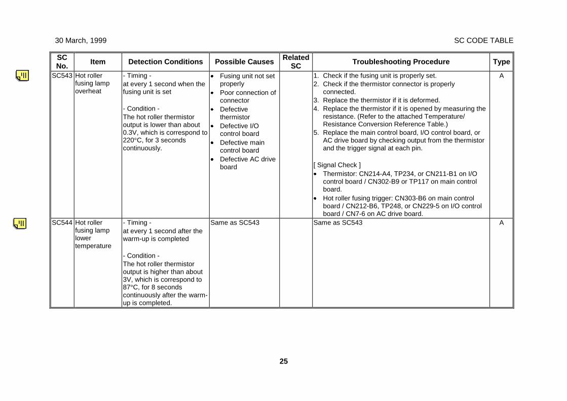
30 March, 1999 SC CODE TABLE
25
SCNo. Item Detection Conditions Possible Causes Related
SC Troubleshooting Procedure Type
SC543 Hot rollerfusing lampoverheat
- Timing -at every 1 second when thefusing unit is set
- Condition -The hot roller thermistoroutput is lower than about0.3V, which is correspond to220°C, for 3 secondscontinuously.
· Fusing unit not setproperly
· Poor connection ofconnector
· Defectivethermistor
· Defective I/Ocontrol board
· Defective maincontrol board
· Defective AC driveboard
1. Check if the fusing unit is properly set.2. Check if the thermistor connector is properly
connected.3. Replace the thermistor if it is deformed.4. Replace the thermistor if it is opened by measuring the
resistance. (Refer to the attached Temperature/Resistance Conversion Reference Table.)
5. Replace the main control board, I/O control board, orAC drive board by checking output from the thermistorand the trigger signal at each pin.
[ Signal Check ]· Thermistor: CN214-A4, TP234, or CN211-B1 on I/O
control board / CN302-B9 or TP117 on main controlboard.
· Hot roller fusing trigger: CN303-B6 on main controlboard / CN212-B6, TP248, or CN229-5 on I/O controlboard / CN7-6 on AC drive board.
A
SC544 Hot rollerfusing lamplowertemperature
- Timing -at every 1 second after thewarm-up is completed
- Condition -The hot roller thermistoroutput is higher than about3V, which is correspond to87°C, for 8 secondscontinuously after the warm-up is completed.
Same as SC543 Same as SC543 A
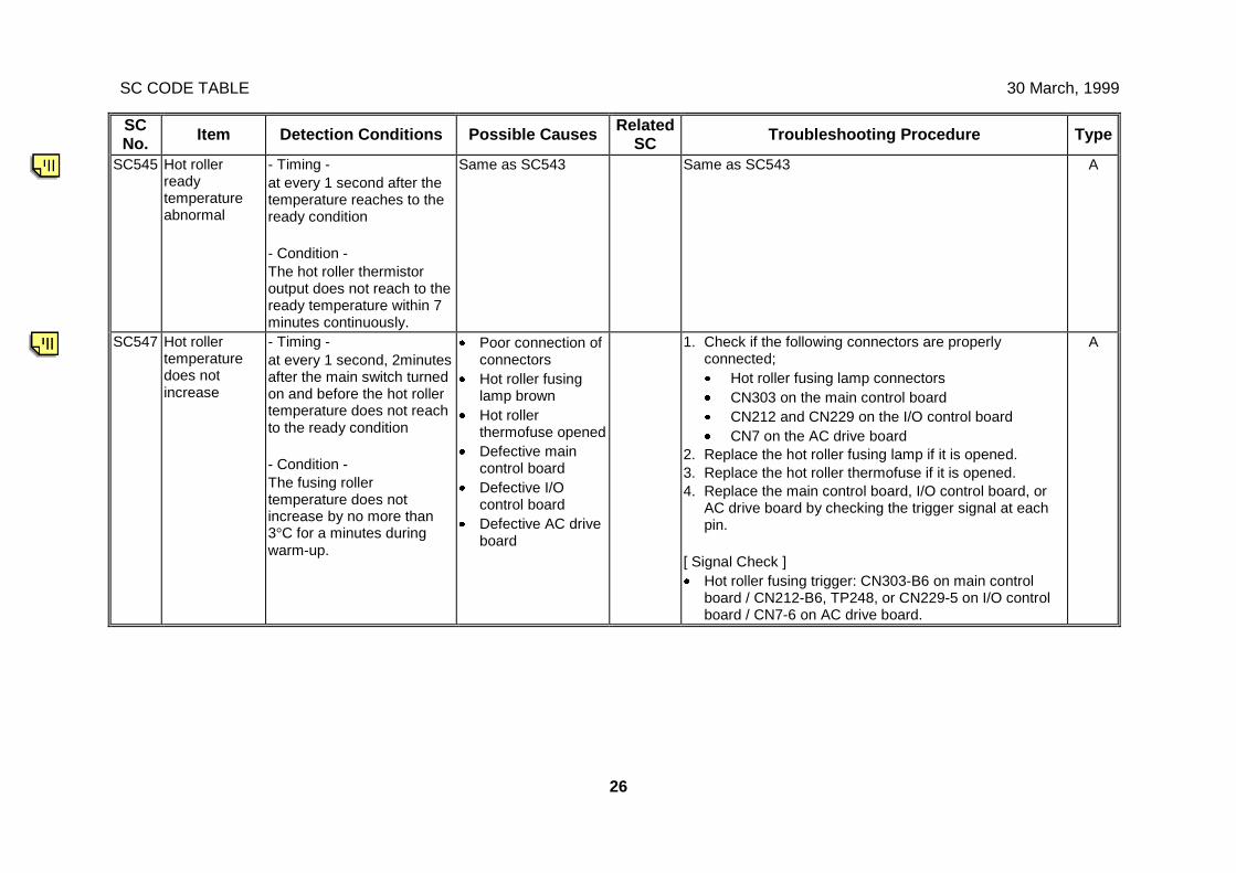
SC CODE TABLE 30 March, 1999
26
SCNo. Item Detection Conditions Possible Causes Related
SC Troubleshooting Procedure Type
SC545 Hot rollerreadytemperatureabnormal
- Timing -at every 1 second after thetemperature reaches to theready condition
- Condition -The hot roller thermistoroutput does not reach to theready temperature within 7minutes continuously.
Same as SC543 Same as SC543 A
SC547 Hot rollertemperaturedoes notincrease
- Timing -at every 1 second, 2minutesafter the main switch turnedon and before the hot rollertemperature does not reachto the ready condition
- Condition -The fusing rollertemperature does notincrease by no more than3°C for a minutes duringwarm-up.
· Poor connection ofconnectors
· Hot roller fusinglamp brown
· Hot rollerthermofuse opened
· Defective maincontrol board
· Defective I/Ocontrol board
· Defective AC driveboard
1. Check if the following connectors are properlyconnected;· Hot roller fusing lamp connectors· CN303 on the main control board· CN212 and CN229 on the I/O control board· CN7 on the AC drive board
2. Replace the hot roller fusing lamp if it is opened.3. Replace the hot roller thermofuse if it is opened.4. Replace the main control board, I/O control board, or
AC drive board by checking the trigger signal at eachpin.
[ Signal Check ]· Hot roller fusing trigger: CN303-B6 on main control
board / CN212-B6, TP248, or CN229-5 on I/O controlboard / CN7-6 on AC drive board.
A
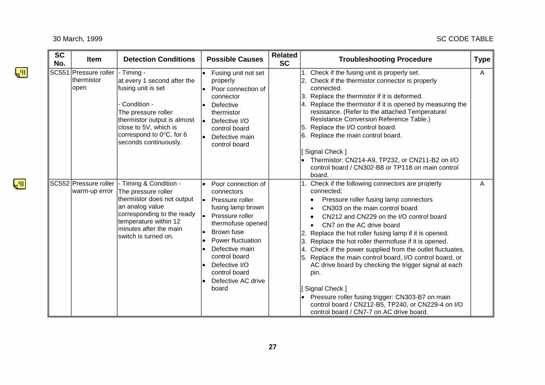
30 March, 1999 SC CODE TABLE
27
SCNo. Item Detection Conditions Possible Causes Related
SC Troubleshooting Procedure Type
SC551 Pressure rollerthermistoropen
- Timing -at every 1 second after thefusing unit is set
- Condition -The pressure rollerthermistor output is almostclose to 5V, which iscorrespond to 0°C, for 6seconds continuously.
· Fusing unit not setproperly
· Poor connection ofconnector
· Defectivethermistor
· Defective I/Ocontrol board
· Defective maincontrol board
1. Check if the fusing unit is properly set.2. Check if the thermistor connector is properly
connected.3. Replace the thermistor if it is deformed.4. Replace the thermistor if it is opened by measuring the
resistance. (Refer to the attached Temperature/Resistance Conversion Reference Table.)
5. Replace the I/O control board.6. Replace the main control board.
[ Signal Check ]· Thermistor: CN214-A9, TP232, or CN211-B2 on I/O
control board / CN302-B8 or TP118 on main controlboard.
A
SC552 Pressure rollerwarm-up error
- Timing & Condition -The pressure rollerthermistor does not outputan analog valuecorresponding to the readytemperature within 12minutes after the mainswitch is turned on.
· Poor connection ofconnectors
· Pressure rollerfusing lamp brown
· Pressure rollerthermofuse opened
· Brown fuse· Power fluctuation· Defective main
control board· Defective I/O
control board· Defective AC drive
board
1. Check if the following connectors are properlyconnected;· Pressure roller fusing lamp connectors· CN303 on the main control board· CN212 and CN229 on the I/O control board· CN7 on the AC drive board
2. Replace the hot roller fusing lamp if it is opened.3. Replace the hot roller thermofuse if it is opened.4. Check if the power supplied from the outlet fluctuates.5. Replace the main control board, I/O control board, or
AC drive board by checking the trigger signal at eachpin.
[ Signal Check ]· Pressure roller fusing trigger: CN303-B7 on main
control board / CN212-B5, TP240, or CN229-4 on I/Ocontrol board / CN7-7 on AC drive board.
A
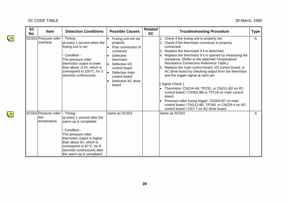
SC CODE TABLE 30 March, 1999
28
SCNo. Item Detection Conditions Possible Causes Related
SC Troubleshooting Procedure Type
SC553 Pressure rolleroverheat
- Timing -at every 1 second when thefusing unit is set
- Condition -The pressure rollerthermistor output is lowerthan about 0.3V, which iscorrespond to 220°C, for 3seconds continuously.
· Fusing unit not setproperly
· Poor connection ofconnector
· Defectivethermistor
· Defective I/Ocontrol board
· Defective maincontrol board
· Defective AC driveboard
1. Check if the fusing unit is properly set.2. Check if the thermistor connector is properly
connected.3. Replace the thermistor if it is deformed.4. Replace the thermistor if it is opened by measuring the
resistance. (Refer to the attached Temperature/Resistance Conversion Reference Table.)
5. Replace the main control board, I/O control board, orAC drive board by checking output from the thermistorand the trigger signal at each pin.
[ Signal Check ]· Thermistor: CN214-A9, TP232, or CN211-B2 on I/O
control board / CN302-B8 or TP118 on main controlboard.
· Pressure roller fusing trigger: CN303-B7 on maincontrol board / CN212-B5, TP240, or CN229-4 on I/Ocontrol board / CN7-7 on AC drive board.
A
SC554 Pressure rollerlowtemperature
- Timing -at every 1 second after thewarm-up is completed
- Condition -The pressure rollerthermistor output is higherthan about 3V, which iscorrespond to 87°C, for 8seconds continuously afterthe warm-up is completed.
Same as SC553 Same as SC553 A
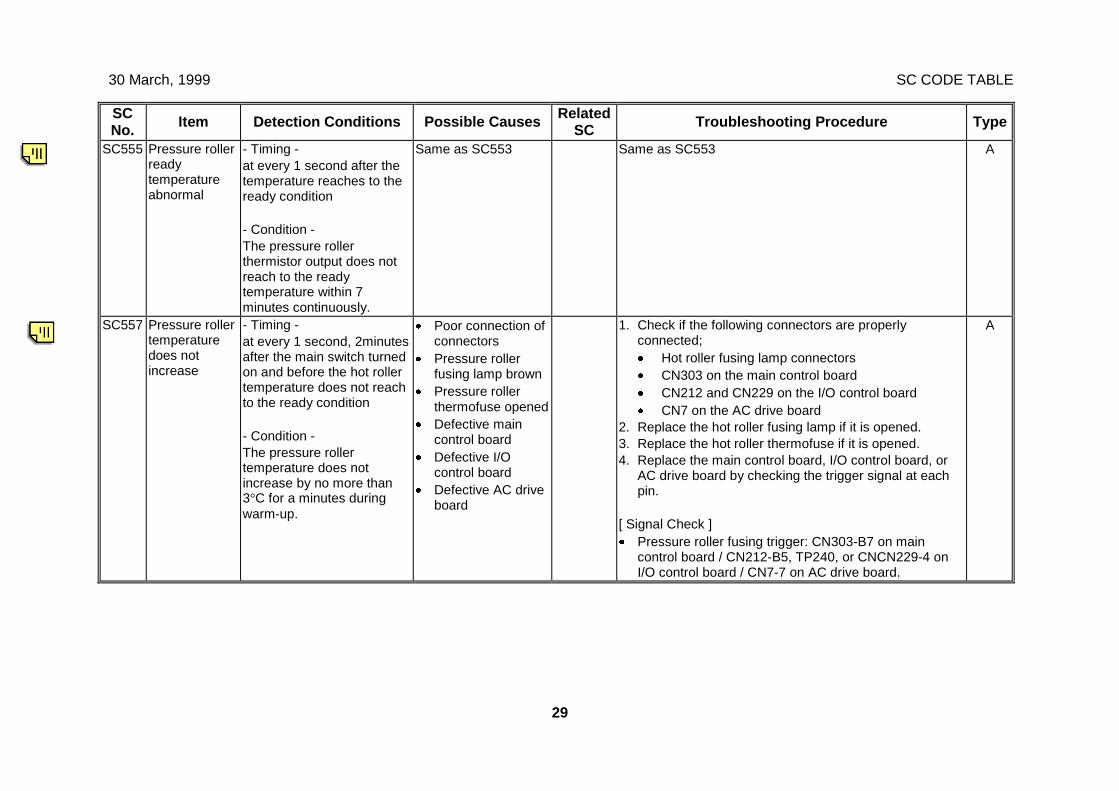
30 March, 1999 SC CODE TABLE
29
SCNo. Item Detection Conditions Possible Causes Related
SC Troubleshooting Procedure Type
SC555 Pressure rollerreadytemperatureabnormal
- Timing -at every 1 second after thetemperature reaches to theready condition
- Condition -The pressure rollerthermistor output does notreach to the readytemperature within 7minutes continuously.
Same as SC553 Same as SC553 A
SC557 Pressure rollertemperaturedoes notincrease
- Timing -at every 1 second, 2minutesafter the main switch turnedon and before the hot rollertemperature does not reachto the ready condition
- Condition -The pressure rollertemperature does notincrease by no more than3°C for a minutes duringwarm-up.
· Poor connection ofconnectors
· Pressure rollerfusing lamp brown
· Pressure rollerthermofuse opened
· Defective maincontrol board
· Defective I/Ocontrol board
· Defective AC driveboard
1. Check if the following connectors are properlyconnected;· Hot roller fusing lamp connectors· CN303 on the main control board· CN212 and CN229 on the I/O control board· CN7 on the AC drive board
2. Replace the hot roller fusing lamp if it is opened.3. Replace the hot roller thermofuse if it is opened.4. Replace the main control board, I/O control board, or
AC drive board by checking the trigger signal at eachpin.
[ Signal Check ]· Pressure roller fusing trigger: CN303-B7 on main
control board / CN212-B5, TP240, or CNCN229-4 onI/O control board / CN7-7 on AC drive board.
A
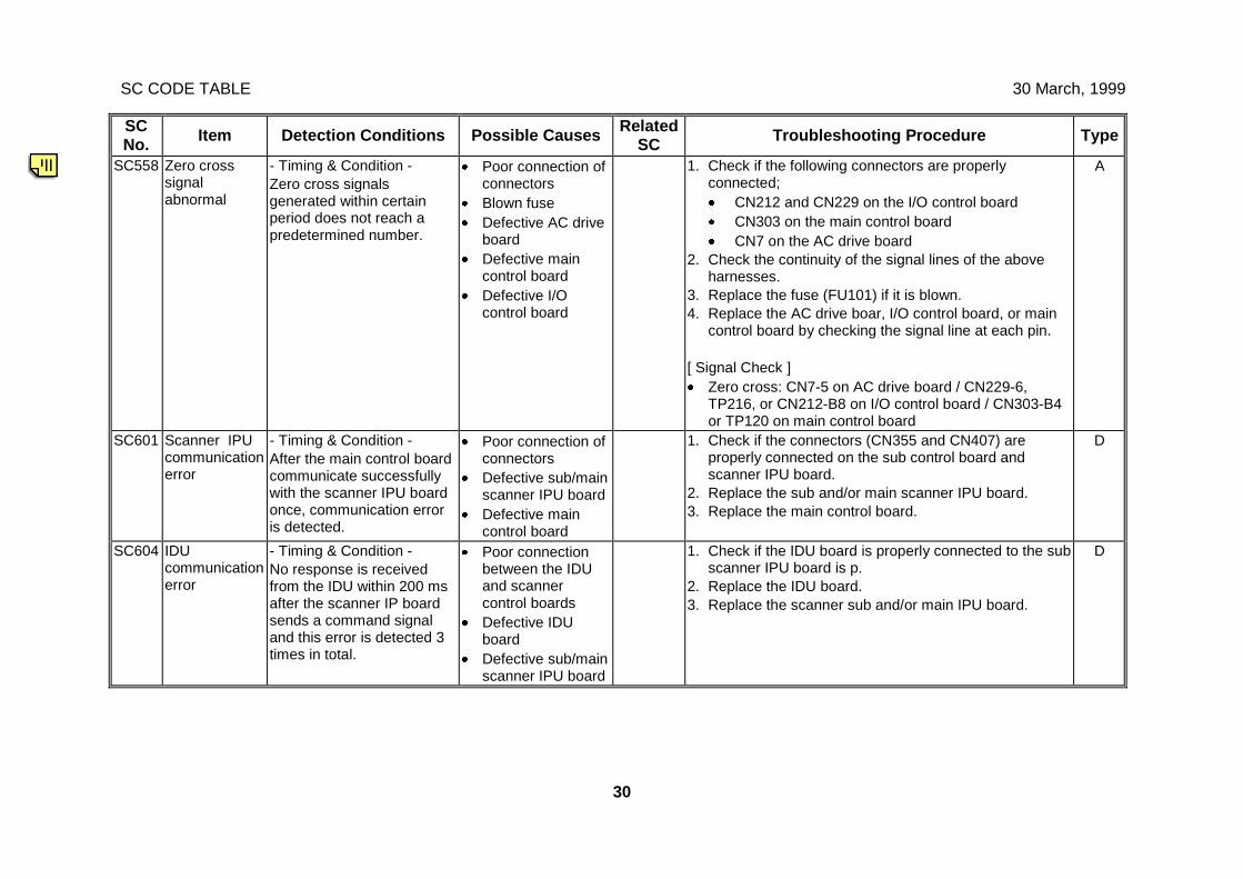
SC CODE TABLE 30 March, 1999
30
SCNo. Item Detection Conditions Possible Causes Related
SC Troubleshooting Procedure Type
SC558 Zero crosssignalabnormal
- Timing & Condition -Zero cross signalsgenerated within certainperiod does not reach apredetermined number.
· Poor connection ofconnectors
· Blown fuse· Defective AC drive
board· Defective main
control board· Defective I/O
control board
1. Check if the following connectors are properlyconnected;· CN212 and CN229 on the I/O control board· CN303 on the main control board· CN7 on the AC drive board
2. Check the continuity of the signal lines of the aboveharnesses.
3. Replace the fuse (FU101) if it is blown.4. Replace the AC drive boar, I/O control board, or main
control board by checking the signal line at each pin.
[ Signal Check ]· Zero cross: CN7-5 on AC drive board / CN229-6,
TP216, or CN212-B8 on I/O control board / CN303-B4or TP120 on main control board
A
SC601 Scanner IPUcommunicationerror
- Timing & Condition -After the main control boardcommunicate successfullywith the scanner IPU boardonce, communication erroris detected.
· Poor connection ofconnectors
· Defective sub/mainscanner IPU board
· Defective maincontrol board
1. Check if the connectors (CN355 and CN407) areproperly connected on the sub control board andscanner IPU board.
2. Replace the sub and/or main scanner IPU board.3. Replace the main control board.
D
SC604 IDUcommunicationerror
- Timing & Condition -No response is receivedfrom the IDU within 200 msafter the scanner IP boardsends a command signaland this error is detected 3times in total.
· Poor connectionbetween the IDUand scannercontrol boards
· Defective IDUboard
· Defective sub/mainscanner IPU board
1. Check if the IDU board is properly connected to the subscanner IPU board is p.
2. Replace the IDU board.3. Replace the scanner sub and/or main IPU board.
D
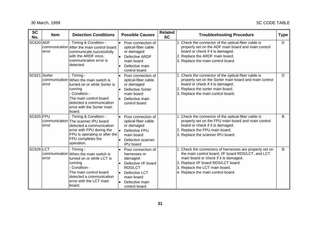
30 March, 1999 SC CODE TABLE
31
SCNo. Item Detection Conditions Possible Causes Related
SC Troubleshooting Procedure Type
SC620 ADFcommunicationerror
- Timing & Condition -After the main control boardcommunicate successfullywith the ARDF once,communication error isdetected.
· Poor connection ofoptical-fiber cableor damaged
· Defective ARDFmain board
· Defective maincontrol board
1. Check the connector of the optical-fiber cable isproperly set on the ADF main board and main controlboard or check if it is damaged.
2. Replace the ARDF main board.3. Replace the main control board.
D
SC621 Sortercommunicationerror
- Timing -When the main switch isturned on or while Sorter isrunning- Condition -The main control boarddetected a communicationerror with the Sorter mainboard.
· Poor connection ofoptical-fiber cableor damaged
· Defective Sortermain board
· Defective maincontrol board
1. Check the connector of the optical-fiber cable isproperly set on the Sorter main board and main controlboard or check if it is damaged.
2. Replace the sorter main board.3. Replace the main control board.
D
SC625 FPUcommunicationerror
- Timing & Condition -The scanner IPU boarddetected a communicationerror with FPU during theFPU is operating or after theFPU completes theoperation.
· Poor connection ofoptical-fiber cableor damaged
· Defective FPUmain board
· Defective scannerIPU board
1. Check the connector of the optical-fiber cable isproperly set on the FPU main board and main controlboard or check if it is damaged.
2. Replace the FPU main board.3. Replace the scanner IPU board.
B
SC626 LCTcommunicationerror
- Timing -When the main switch isturned on or while LCT isrunning- Condition -The main control boarddetected a communicationerror with the LCT mainboard.
· Poor connection ofharnesses ordamaged
· Defective I/F boardRDS/LCT
· Defective LCTmain board
· Defective maincontrol board
1. Check the connectors of harnesses are properly set onthe main control board, I/F board RDS/LCT, and LCTmain board or check if it is damaged.
2. Replace I/F board RDS/LCT board.3. Replace the LCT main board.4. Replace the main control board.
B
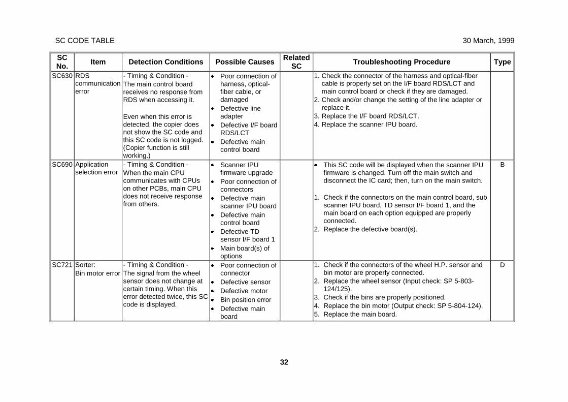
SC CODE TABLE 30 March, 1999
32
SCNo. Item Detection Conditions Possible Causes Related
SC Troubleshooting Procedure Type
SC630 RDScommunicationerror
- Timing & Condition -The main control boardreceives no response fromRDS when accessing it.
Even when this error isdetected, the copier doesnot show the SC code andthis SC code is not logged.(Copier function is stillworking.)
· Poor connection ofharness, optical-fiber cable, ordamaged
· Defective lineadapter
· Defective I/F boardRDS/LCT
· Defective maincontrol board
1. Check the connector of the harness and optical-fibercable is properly set on the I/F board RDS/LCT andmain control board or check if they are damaged.
2. Check and/or change the setting of the line adapter orreplace it.
3. Replace the I/F board RDS/LCT.4. Replace the scanner IPU board.
SC690 Applicationselection error
- Timing & Condition -When the main CPUcommunicates with CPUson other PCBs, main CPUdoes not receive responsefrom others.
· Scanner IPUfirmware upgrade
· Poor connection ofconnectors
· Defective mainscanner IPU board
· Defective maincontrol board
· Defective TDsensor I/F board 1
· Main board(s) ofoptions
· This SC code will be displayed when the scanner IPUfirmware is changed. Turn off the main switch anddisconnect the IC card; then, turn on the main switch.
1. Check if the connectors on the main control board, subscanner IPU board, TD sensor I/F board 1, and themain board on each option equipped are properlyconnected.
2. Replace the defective board(s).
B
SC721 Sorter:Bin motor error
- Timing & Condition -The signal from the wheelsensor does not change atcertain timing. When thiserror detected twice, this SCcode is displayed.
· Poor connection ofconnector
· Defective sensor· Defective motor· Bin position error· Defective main
board
1. Check if the connectors of the wheel H.P. sensor andbin motor are properly connected.
2. Replace the wheel sensor (Input check: SP 5-803-124/125).
3. Check if the bins are properly positioned.4. Replace the bin motor (Output check: SP 5-804-124).5. Replace the main board.
D
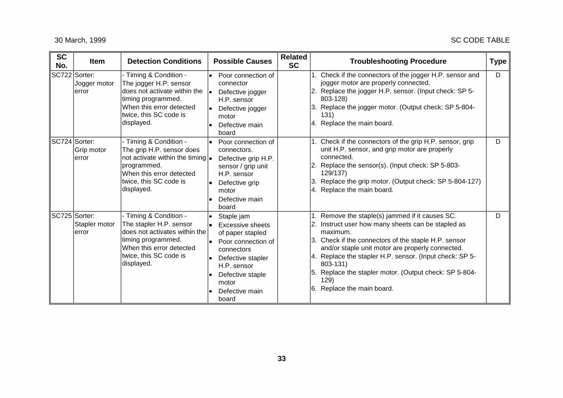
30 March, 1999 SC CODE TABLE
33
SCNo. Item Detection Conditions Possible Causes Related
SC Troubleshooting Procedure Type
SC722 Sorter:Jogger motorerror
- Timing & Condition -The jogger H.P. sensordoes not activate within thetiming programmed.When this error detectedtwice, this SC code isdisplayed.
· Poor connection ofconnector
· Defective joggerH.P. sensor
· Defective joggermotor
· Defective mainboard
1. Check if the connectors of the jogger H.P. sensor andjogger motor are properly connected.
2. Replace the jogger H.P. sensor. (Input check: SP 5-803-128)
3. Replace the jogger motor. (Output check: SP 5-804-131)
4. Replace the main board.
D
SC724 Sorter:Grip motorerror
- Timing & Condition -The grip H.P. sensor doesnot activate within the timingprogrammed.When this error detectedtwice, this SC code isdisplayed.
· Poor connection ofconnectors.
· Defective grip H.P.sensor / grip unitH.P. sensor
· Defective gripmotor
· Defective mainboard
1. Check if the connectors of the grip H.P. sensor, gripunit H.P. sensor, and grip motor are properlyconnected.
2. Replace the sensor(s). (Input check: SP 5-803-129/137)
3. Replace the grip motor. (Output check: SP 5-804-127)4. Replace the main board.
D
SC725 Sorter:Stapler motorerror
- Timing & Condition -The stapler H.P. sensordoes not activates within thetiming programmed.When this error detectedtwice, this SC code isdisplayed.
· Staple jam· Excessive sheets
of paper stapled· Poor connection of
connectors· Defective stapler
H.P. sensor· Defective staple
motor· Defective main
board
1. Remove the staple(s) jammed if it causes SC.2. Instruct user how many sheets can be stapled as
maximum.3. Check if the connectors of the staple H.P. sensor
and/or staple unit motor are properly connected.4. Replace the stapler H.P. sensor. (Input check: SP 5-
803-131)5. Replace the stapler motor. (Output check: SP 5-804-
129)6. Replace the main board.
D
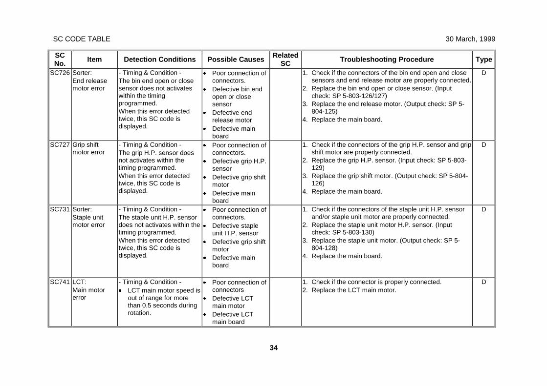
SC CODE TABLE 30 March, 1999
34
SCNo. Item Detection Conditions Possible Causes Related
SC Troubleshooting Procedure Type
SC726 Sorter:End releasemotor error
- Timing & Condition -The bin end open or closesensor does not activateswithin the timingprogrammed.When this error detectedtwice, this SC code isdisplayed.
· Poor connection ofconnectors.
· Defective bin endopen or closesensor
· Defective endrelease motor
· Defective mainboard
1. Check if the connectors of the bin end open and closesensors and end release motor are properly connected.
2. Replace the bin end open or close sensor. (Inputcheck: SP 5-803-126/127)
3. Replace the end release motor. (Output check: SP 5-804-125)
4. Replace the main board.
D
SC727 Grip shiftmotor error
- Timing & Condition -The grip H.P. sensor doesnot activates within thetiming programmed.When this error detectedtwice, this SC code isdisplayed.
· Poor connection ofconnectors.
· Defective grip H.P.sensor
· Defective grip shiftmotor
· Defective mainboard
1. Check if the connectors of the grip H.P. sensor and gripshift motor are properly connected.
2. Replace the grip H.P. sensor. (Input check: SP 5-803-129)
3. Replace the grip shift motor. (Output check: SP 5-804-126)
4. Replace the main board.
D
SC731 Sorter:Staple unitmotor error
- Timing & Condition -The staple unit H.P. sensordoes not activates within thetiming programmed.When this error detectedtwice, this SC code isdisplayed.
· Poor connection ofconnectors.
· Defective stapleunit H.P. sensor
· Defective grip shiftmotor
· Defective mainboard
1. Check if the connectors of the staple unit H.P. sensorand/or staple unit motor are properly connected.
2. Replace the staple unit motor H.P. sensor. (Inputcheck: SP 5-803-130)
3. Replace the staple unit motor. (Output check: SP 5-804-128)
4. Replace the main board.
D
SC741 LCT:Main motorerror
- Timing & Condition -· LCT main motor speed is
out of range for morethan 0.5 seconds duringrotation.
· Poor connection ofconnectors
· Defective LCTmain motor
· Defective LCTmain board
1. Check if the connector is properly connected.2. Replace the LCT main motor.
D
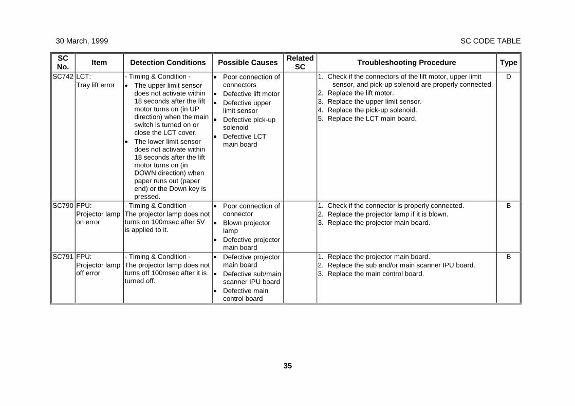
30 March, 1999 SC CODE TABLE
35
SCNo. Item Detection Conditions Possible Causes Related
SC Troubleshooting Procedure Type
SC742 LCT:Tray lift error
- Timing & Condition -· The upper limit sensor
does not activate within18 seconds after the liftmotor turns on (in UPdirection) when the mainswitch is turned on orclose the LCT cover.
· The lower limit sensordoes not activate within18 seconds after the liftmotor turns on (inDOWN direction) whenpaper runs out (paperend) or the Down key ispressed.
· Poor connection ofconnectors
· Defective lift motor· Defective upper
limit sensor· Defective pick-up
solenoid· Defective LCT
main board
1. Check if the connectors of the lift motor, upper limitsensor, and pick-up solenoid are properly connected.
2. Replace the lift motor.3. Replace the upper limit sensor.4. Replace the pick-up solenoid.5. Replace the LCT main board.
D
SC790 FPU:Projector lampon error
- Timing & Condition -The projector lamp does notturns on 100msec after 5Vis applied to it.
· Poor connection ofconnector
· Blown projectorlamp
· Defective projectormain board
1. Check if the connector is properly connected.2. Replace the projector lamp if it is blown.3. Replace the projector main board.
B
SC791 FPU:Projector lampoff error
- Timing & Condition -The projector lamp does notturns off 100msec after it isturned off.
· Defective projectormain board
· Defective sub/mainscanner IPU board
· Defective maincontrol board
1. Replace the projector main board.2. Replace the sub and/or main scanner IPU board.3. Replace the main control board.
B
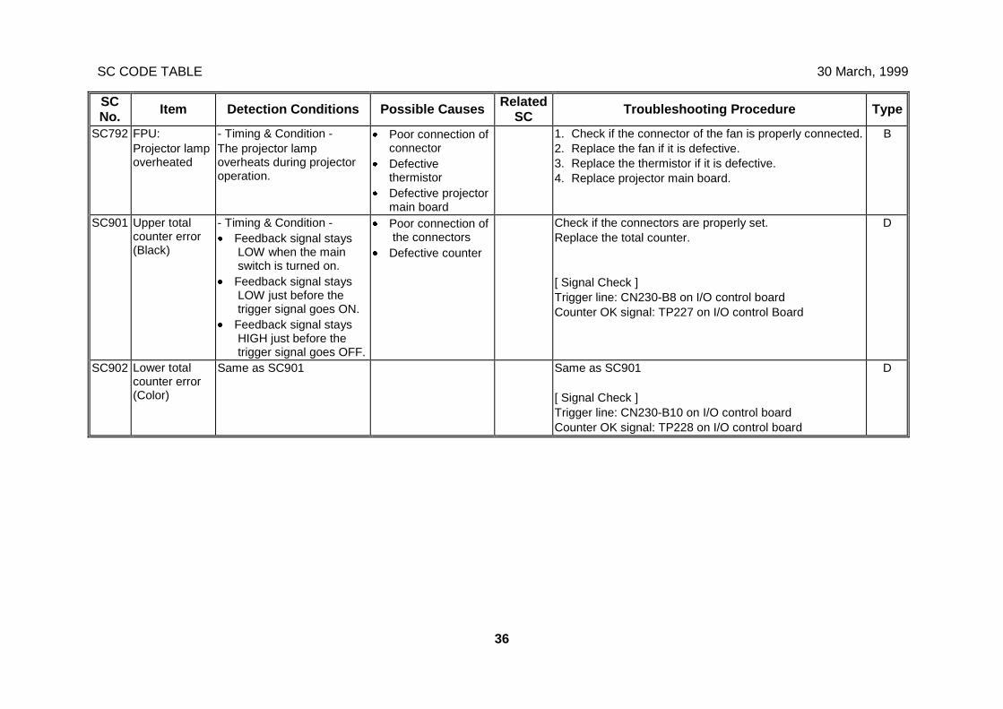
SC CODE TABLE 30 March, 1999
36
SCNo. Item Detection Conditions Possible Causes Related
SC Troubleshooting Procedure Type
SC792 FPU:Projector lampoverheated
- Timing & Condition -The projector lampoverheats during projectoroperation.
· Poor connection ofconnector
· Defectivethermistor
· Defective projectormain board
1. Check if the connector of the fan is properly connected.2. Replace the fan if it is defective.3. Replace the thermistor if it is defective.4. Replace projector main board.
B
SC901 Upper totalcounter error(Black)
- Timing & Condition -· Feedback signal stays
LOW when the mainswitch is turned on.
· Feedback signal staysLOW just before thetrigger signal goes ON.
· Feedback signal staysHIGH just before thetrigger signal goes OFF.
· Poor connection ofthe connectors
· Defective counter
Check if the connectors are properly set.Replace the total counter.
[ Signal Check ]Trigger line: CN230-B8 on I/O control boardCounter OK signal: TP227 on I/O control Board
D
SC902 Lower totalcounter error(Color)
Same as SC901 Same as SC901
[ Signal Check ]Trigger line: CN230-B10 on I/O control boardCounter OK signal: TP228 on I/O control board
D
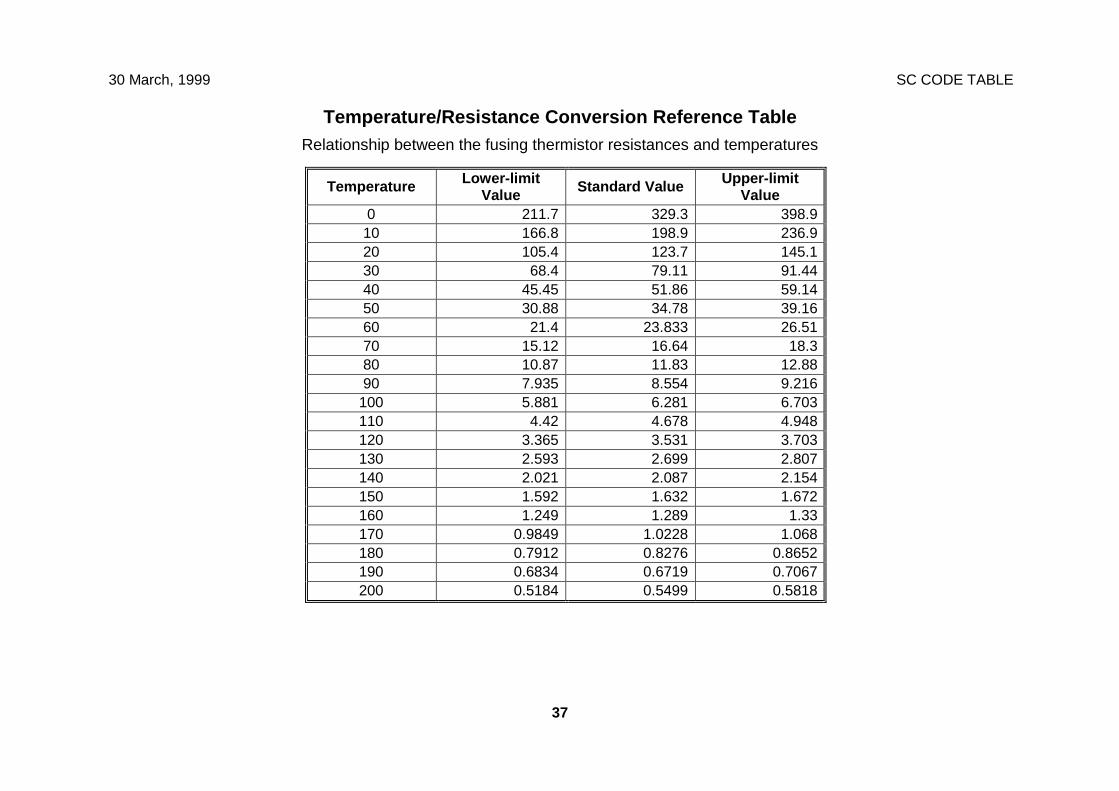
30 March, 1999 SC CODE TABLE
37
Temperature/Resistance Conversion Reference TableRelationship between the fusing thermistor resistances and temperatures
Temperature Lower-limitValue Standard Value Upper-limit
Value0 211.7 329.3 398.910 166.8 198.9 236.920 105.4 123.7 145.130 68.4 79.11 91.4440 45.45 51.86 59.1450 30.88 34.78 39.1660 21.4 23.833 26.5170 15.12 16.64 18.380 10.87 11.83 12.8890 7.935 8.554 9.216
100 5.881 6.281 6.703110 4.42 4.678 4.948120 3.365 3.531 3.703130 2.593 2.699 2.807140 2.021 2.087 2.154150 1.592 1.632 1.672160 1.249 1.289 1.33170 0.9849 1.0228 1.068180 0.7912 0.8276 0.8652190 0.6834 0.6719 0.7067200 0.5184 0.5499 0.5818

APPENDIX-2
SP MODE
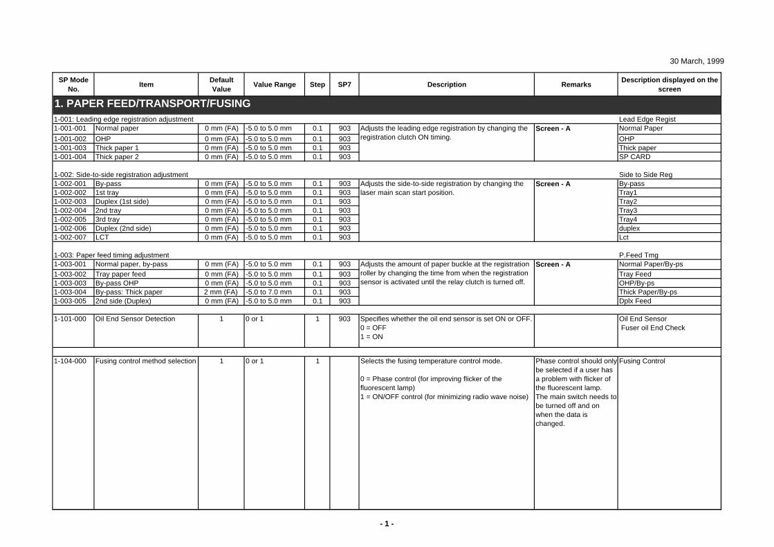
30 March, 1999
SP Mode No.
ItemDefault Value
Value Range Step SP7 Description RemarksDescription displayed on the
screen
1-001: Leading edge registration adjustment Lead Edge Regist1-001-001 Normal paper 0 mm (FA) -5.0 to 5.0 mm 0.1 903 Normal Paper
1-001-002 OHP 0 mm (FA) -5.0 to 5.0 mm 0.1 903 OHP1-001-003 Thick paper 1 0 mm (FA) -5.0 to 5.0 mm 0.1 903 Thick paper1-001-004 Thick paper 2 0 mm (FA) -5.0 to 5.0 mm 0.1 903 SP CARD
1-002: Side-to-side registration adjustment Side to Side Reg1-002-001 By-pass 0 mm (FA) -5.0 to 5.0 mm 0.1 903 By-pass1-002-002 1st tray 0 mm (FA) -5.0 to 5.0 mm 0.1 903 Tray11-002-003 Duplex (1st side) 0 mm (FA) -5.0 to 5.0 mm 0.1 903 Tray21-002-004 2nd tray 0 mm (FA) -5.0 to 5.0 mm 0.1 903 Tray31-002-005 3rd tray 0 mm (FA) -5.0 to 5.0 mm 0.1 903 Tray41-002-006 Duplex (2nd side) 0 mm (FA) -5.0 to 5.0 mm 0.1 903 duplex1-002-007 LCT 0 mm (FA) -5.0 to 5.0 mm 0.1 903 Lct
1-003: Paper feed timing adjustment P.Feed Tmg1-003-001 Normal paper, by-pass 0 mm (FA) -5.0 to 5.0 mm 0.1 903 Normal Paper/By-ps1-003-002 Tray paper feed 0 mm (FA) -5.0 to 5.0 mm 0.1 903 Tray Feed1-003-003 By-pass OHP 0 mm (FA) -5.0 to 5.0 mm 0.1 903 OHP/By-ps1-003-004 By-pass: Thick paper 2 mm (FA) -5.0 to 7.0 mm 0.1 903 Thick Paper/By-ps1-003-005 2nd side (Duplex) 0 mm (FA) -5.0 to 5.0 mm 0.1 903 Dplx Feed
1-101-000 Oil End Sensor Detection 1 0 or 1 1 903 Specifies whether the oil end sensor is set ON or OFF.0 = OFF1 = ON
Oil End Sensor Fuser oil End Check
1-104-000 Fusing control method selection 1 0 or 1 1 Selects the fusing temperature control mode.
0 = Phase control (for improving flicker of the fluorescent lamp)1 = ON/OFF control (for minimizing radio wave noise)
Phase control should only be selected if a user has a problem with flicker of the fluorescent lamp.The main switch needs to be turned off and on when the data is changed.
Fusing Control
1. PAPER FEED/TRANSPORT/FUSING
Adjusts the side-to-side registration by changing the laser main scan start position.
Adjusts the leading edge registration by changing the registration clutch ON timing.
Adjusts the amount of paper buckle at the registration roller by changing the time from when the registration sensor is activated until the relay clutch is turned off.
Screen - A
Screen - A
Screen - A
- 1 -
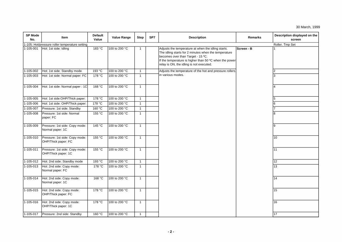
30 March, 1999
SP Mode No.
ItemDefault Value
Value Range Step SP7 Description RemarksDescription displayed on the
screen
1-105: Hot/pressure roller temperature setting Roller. Tmp Set1-105-001 Hot: 1st side: Idling 183 °C 100 to 200 °C 1 Adjusts the temperature at when the idling starts.
The idling starts for 2 minutes when the temperature becomes over than Target - 15 ºC.If the temperature is higher than 50 ºC when the power relay is ON, the idling is not executed.
1
1-105-002 Hot: 1st side: Standby mode 193 °C 100 to 200 °C 1 2
1-105-003 Hot: 1st side: Normal paper: FC 178 °C 100 to 200 °C 1 3
1-105-004 Hot: 1st side: Normal paper : 1C 168 °C 100 to 200 °C 1 4
1-105-005 Hot: 1st side:OHP/Thick paper: FC
178 °C 100 to 200 °C 1 5
1-105-006 Hot: 1st side: OHP/Thick paper: C
178 °C 100 to 200 °C 1 6
1-105-007 Pressure: 1st side: Standby 160 °C 100 to 200 °C 1 7
1-105-008 Pressure: 1st side: Normal paper: FC
155 °C 100 to 200 °C 1 8
1-105-009 Pressure: 1st side: Copy mode: Normal paper: 1C
145 °C 100 to 200 °C 1 9
1-105-010 Pressure: 1st side: Copy mode: OHP/Thick paper: FC
155 °C 100 to 200 °C 1 10
1-105-011 Pressure: 1st side: Copy mode: OHP/Thick paper: 1C
155 °C 100 to 200 °C 1 11
1-105-012 Hot: 2nd side: Standby mode 193 °C 100 to 200 °C 1 12
1-105-013 Hot: 2nd side: Copy mode: Normal paper: FC
178 °C 100 to 200 °C 1 13
1-105-014 Hot: 2nd side: Copy mode: Normal paper: 1C
168 °C 100 to 200 °C 1 14
1-105-015 Hot: 2nd side: Copy mode: OHP/Thick paper: FC
178 °C 100 to 200 °C 1 15
1-105-016 Hot: 2nd side: Copy mode: OHP/Thick paper: 1C
178 °C 100 to 200 °C 1 16
1-105-017 Pressure: 2nd side: Standby d
160 °C 100 to 200 °C 1 17
Adjusts the temperature of the hot and pressure rollers in various modes.
Screen - B
- 2 -
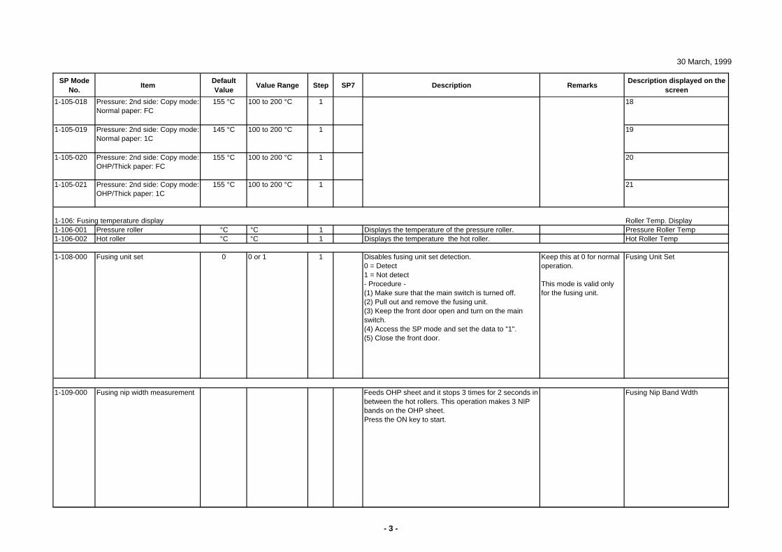
30 March, 1999
SP Mode No.
ItemDefault Value
Value Range Step SP7 Description RemarksDescription displayed on the
screen
1-105-018 Pressure: 2nd side: Copy mode: Normal paper: FC
155 °C 100 to 200 °C 1 18
1-105-019 Pressure: 2nd side: Copy mode: Normal paper: 1C
145 °C 100 to 200 °C 1 19
1-105-020 Pressure: 2nd side: Copy mode: OHP/Thick paper: FC
155 °C 100 to 200 °C 1 20
1-105-021 Pressure: 2nd side: Copy mode: OHP/Thick paper: 1C
155 °C 100 to 200 °C 1 21
1-106: Fusing temperature display Roller Temp. Display1-106-001 Pressure roller °C °C 1 Displays the temperature of the pressure roller. Pressure Roller Temp1-106-002 Hot roller °C °C 1 Displays the temperature the hot roller. Hot Roller Temp
1-108-000 Fusing unit set 0 0 or 1 1 Disables fusing unit set detection.0 = Detect1 = Not detect- Procedure -(1) Make sure that the main switch is turned off.(2) Pull out and remove the fusing unit.(3) Keep the front door open and turn on the main switch.(4) Access the SP mode and set the data to "1".(5) Close the front door.
Keep this at 0 for normal operation.
This mode is valid only for the fusing unit.
Fusing Unit Set
1-109-000 Fusing nip width measurement Feeds OHP sheet and it stops 3 times for 2 seconds in between the hot rollers. This operation makes 3 NIP bands on the OHP sheet.Press the ON key to start.
Fusing Nip Band Wdth
- 3 -
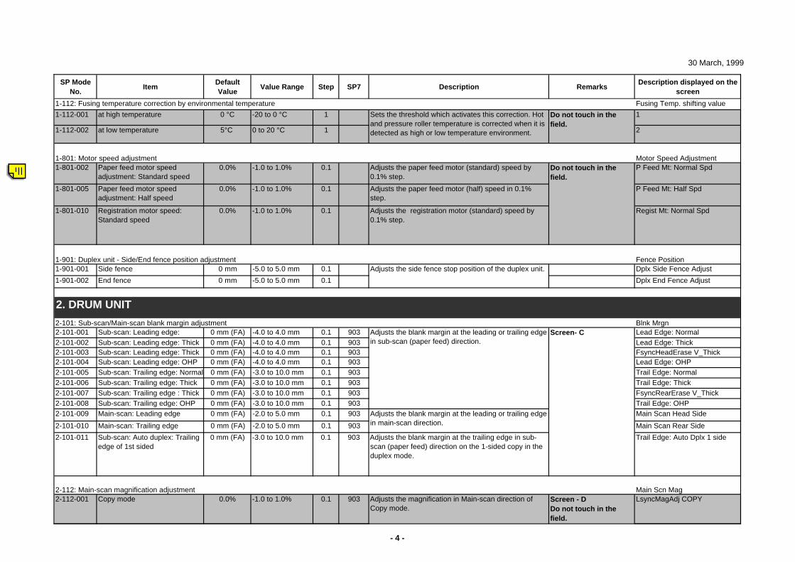
30 March, 1999
SP Mode No.
ItemDefault Value
Value Range Step SP7 Description RemarksDescription displayed on the
screen
1-112: Fusing temperature correction by environmental temperature Fusing Temp. shifting value
1-112-001 at high temperature 0 °C -20 to 0 °C 1 1
1-112-002 at low temperature 5°C 0 to 20 °C 1 2
1-801: Motor speed adjustment Motor Speed Adjustment1-801-002 Paper feed motor speed
adjustment: Standard speed0.0% -1.0 to 1.0% 0.1 Adjusts the paper feed motor (standard) speed by
0.1% step.P Feed Mt: Normal Spd
1-801-005 Paper feed motor speed adjustment: Half speed
0.0% -1.0 to 1.0% 0.1 Adjusts the paper feed motor (half) speed in 0.1% step.
P Feed Mt: Half Spd
1-801-010 Registration motor speed: Standard speed
0.0% -1.0 to 1.0% 0.1 Adjusts the registration motor (standard) speed by 0.1% step.
Regist Mt: Normal Spd
1-901: Duplex unit - Side/End fence position adjustment Fence Position1-901-001 Side fence 0 mm -5.0 to 5.0 mm 0.1 Dplx Side Fence Adjust
1-901-002 End fence 0 mm -5.0 to 5.0 mm 0.1 Dplx End Fence Adjust
2-101: Sub-scan/Main-scan blank margin adjustment Blnk Mrgn2-101-001 Sub-scan: Leading edge: 0 mm (FA) -4.0 to 4.0 mm 0.1 903 Lead Edge: Normal2-101-002 Sub-scan: Leading edge: Thick 0 mm (FA) -4.0 to 4.0 mm 0.1 903 Lead Edge: Thick2-101-003 Sub-scan: Leading edge: Thick 0 mm (FA) -4.0 to 4.0 mm 0.1 903 FsyncHeadErase V_Thick2-101-004 Sub-scan: Leading edge: OHP 0 mm (FA) -4.0 to 4.0 mm 0.1 903 Lead Edge: OHP2-101-005 Sub-scan: Trailing edge: Normal 0 mm (FA) -3.0 to 10.0 mm 0.1 903 Trail Edge: Normal2-101-006 Sub-scan: Trailing edge: Thick 0 mm (FA) -3.0 to 10.0 mm 0.1 903 Trail Edge: Thick2-101-007 Sub-scan: Trailing edge : Thick 0 mm (FA) -3.0 to 10.0 mm 0.1 903 FsyncRearErase V_Thick2-101-008 Sub-scan: Trailing edge: OHP 0 mm (FA) -3.0 to 10.0 mm 0.1 903 Trail Edge: OHP2-101-009 Main-scan: Leading edge 0 mm (FA) -2.0 to 5.0 mm 0.1 903 Main Scan Head Side
2-101-010 Main-scan: Trailing edge 0 mm (FA) -2.0 to 5.0 mm 0.1 903 Main Scan Rear Side
2-101-011 Sub-scan: Auto duplex: Trailing edge of 1st sided
0 mm (FA) -3.0 to 10.0 mm 0.1 903 Adjusts the blank margin at the trailing edge in sub-scan (paper feed) direction on the 1-sided copy in the duplex mode.
Trail Edge: Auto Dplx 1 side
2-112: Main-scan magnification adjustment Main Scn Mag2-112-001 Copy mode 0.0% -1.0 to 1.0% 0.1 903 Adjusts the magnification in Main-scan direction of
Copy mode.Screen - DDo not touch in the field.
LsyncMagAdj COPY
Adjusts the blank margin at the leading or trailing edge in main-scan direction.
Sets the threshold which activates this correction. Hot and pressure roller temperature is corrected when it is detected as high or low temperature environment.
Adjusts the side fence stop position of the duplex unit.
Adjusts the blank margin at the leading or trailing edge in sub-scan (paper feed) direction.
2. DRUM UNIT
Do not touch in the field.
Do not touch in the field.
Screen- C
- 4 -
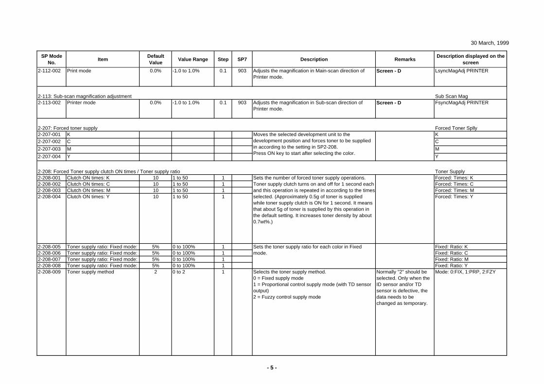
30 March, 1999
SP Mode No.
ItemDefault Value
Value Range Step SP7 Description RemarksDescription displayed on the
screen
2-112-002 Print mode 0.0% -1.0 to 1.0% 0.1 903 Adjusts the magnification in Main-scan direction of Printer mode.
Screen - D LsyncMagAdj PRINTER
Sub Scan Mag2-113-002 Printer mode 0.0% -1.0 to 1.0% 0.1 903 Adjusts the magnification in Sub-scan direction of
Printer mode.Screen - D FsyncMagAdj PRINTER
2-207: Forced toner supply Forced Toner Splly2-207-001 K K2-207-002 C C
2-207-003 M M
2-207-004 Y Y
2-208: Forced Toner supply clutch ON times / Toner supply ratio Toner Supply2-208-001 Clutch ON times: K 10 1 to 50 1 Forced: Times: K2-208-002 Clutch ON times: C 10 1 to 50 1 Forced: Times: C2-208-003 Clutch ON times: M 10 1 to 50 1 Forced: Times: M2-208-004 Clutch ON times: Y 10 1 to 50 1 Forced: Times: Y
2-208-005 Toner supply ratio: Fixed mode: 5% 0 to 100% 1 Fixed: Ratio: K2-208-006 Toner supply ratio: Fixed mode: 5% 0 to 100% 1 Fixed: Ratio: C2-208-007 Toner supply ratio: Fixed mode: 5% 0 to 100% 1 Fixed: Ratio: M2-208-008 Toner supply ratio: Fixed mode: 5% 0 to 100% 1 Fixed: Ratio: Y2-208-009 Toner supply method 2 0 to 2 1 Selects the toner supply method.
0 = Fixed supply mode1 = Proportional control supply mode (with TD sensor output)2 = Fuzzy control supply mode
Normally "2" should be selected. Only when the ID sensor and/or TD sensor is defective, the data needs to be changed as temporary.
Mode: 0:FIX, 1:PRP, 2:FZY
Sets the toner supply ratio for each color in Fixed mode.
Moves the selected development unit to the development position and forces toner to be supplied in according to the setting in SP2-208.Press ON key to start after selecting the color.
2-113: Sub-scan magnification adjustment
Sets the number of forced toner supply operations. Toner supply clutch turns on and off for 1 second each and this operation is repeated in according to the times selected. (Approximately 0.5g of toner is supplied while toner supply clutch is ON for 1 second. It means that about 5g of toner is supplied by this operation in the default setting. It increases toner density by about 0.7wt%.)
- 5 -
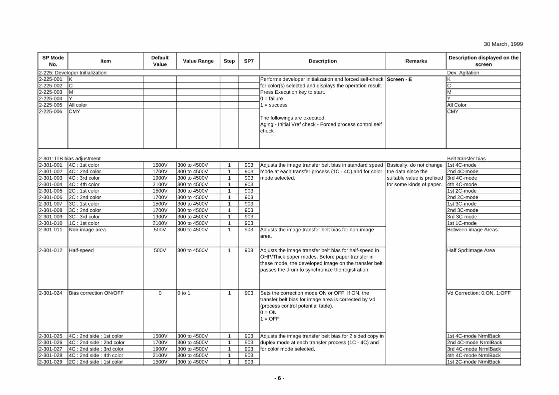
30 March, 1999
SP Mode No.
ItemDefault Value
Value Range Step SP7 Description RemarksDescription displayed on the
screen
2-225: Developer Initialization Dev. Agitation2-225-001 K K2-225-002 C C2-225-003 M M2-225-004 Y Y2-225-005 All color All Color2-225-006 CMY CMY
2-301: ITB bias adjustment Belt transfer bias2-301-001 4C : 1st color 1500V 300 to 4500V 1 903 1st 4C-mode2-301-002 4C : 2nd color 1700V 300 to 4500V 1 903 2nd 4C-mode2-301-003 4C : 3rd color 1900V 300 to 4500V 1 903 3rd 4C-mode2-301-004 4C : 4th color 2100V 300 to 4500V 1 903 4th 4C-mode2-301-005 2C : 1st color 1500V 300 to 4500V 1 903 1st 2C-mode2-301-006 2C : 2nd color 1700V 300 to 4500V 1 903 2nd 2C-mode2-301-007 3C : 1st color 1500V 300 to 4500V 1 903 1st 3C-mode2-301-008 3C : 2nd color 1700V 300 to 4500V 1 903 2nd 3C-mode2-301-009 3C : 3rd color 1900V 300 to 4500V 1 903 3rd 3C-mode2-301-010 1C : 1st color 2100V 300 to 4500V 1 903 1st 1C-mode2-301-011 Non-image area 500V 300 to 4500V 1 903 Adjusts the image transfer belt bias for non-image
area.Between image Areas
2-301-012 Half-speed 500V 300 to 4500V 1 903 Adjusts the image transfer belt bias for half-speed in OHP/Thick paper modes. Before paper transfer in these mode, the developed image on the transfer belt passes the drum to synchronize the registration.
Half Spd:Image Area
2-301-024 Bias correction ON/OFF 0 0 to 1 1 903 Sets the correction mode ON or OFF. If ON, the transfer belt bias for image area is corrected by Vd (process control potential table).0 = ON1 = OFF
Vd Correction: 0:ON, 1:OFF
2-301-025 4C : 2nd side : 1st color 1500V 300 to 4500V 1 903 1st 4C-mode NrmlBack2-301-026 4C : 2nd side : 2nd color 1700V 300 to 4500V 1 903 2nd 4C-mode NrmlBack2-301-027 4C : 2nd side : 3rd color 1900V 300 to 4500V 1 903 3rd 4C-mode NrmlBack2-301-028 4C : 2nd side : 4th color 2100V 300 to 4500V 1 903 4th 4C-mode NrmlBack2-301-029 2C : 2nd side : 1st color 1500V 300 to 4500V 1 903 1st 2C-mode NrmlBack
Adjusts the image transfer belt bias in standard speed mode at each transfer process (1C - 4C) and for color mode selected.
Performs developer initialization and forced self-check for color(s) selected and displays the operation result.Press Execution key to start.0 = failure1 = success
The followings are executed.Aging - Initial Vref check - Forced process control self check
Adjusts the image transfer belt bias for 2 sided copy in duplex mode at each transfer process (1C - 4C) and for color mode selected.
Screen - E
Basically, do not change the data since the suitable value is prefixed for some kinds of paper.
- 6 -
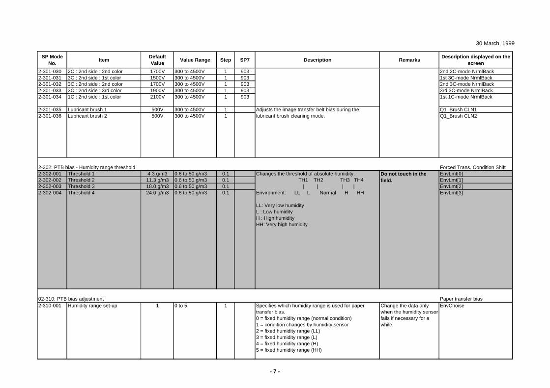
30 March, 1999
SP Mode No.
ItemDefault Value
Value Range Step SP7 Description RemarksDescription displayed on the
screen
2-301-030 2C : 2nd side : 2nd color 1700V 300 to 4500V 1 903 2nd 2C-mode NrmlBack2-301-031 3C : 2nd side : 1st color 1500V 300 to 4500V 1 903 1st 3C-mode NrmlBack2-301-032 3C : 2nd side : 2nd color 1700V 300 to 4500V 1 903 2nd 3C-mode NrmlBack2-301-033 3C : 2nd side : 3rd color 1900V 300 to 4500V 1 903 3rd 3C-mode NrmlBack2-301-034 1C : 2nd side : 1st color 2100V 300 to 4500V 1 903 1st 1C-mode NrmlBack
2-301-035 Lubricant brush 1 500V 300 to 4500V 1 Q1_Brush CLN12-301-036 Lubricant brush 2 500V 300 to 4500V 1 Q1_Brush CLN2
2-302: PTB bias - Humidity range threshold Forced Trans. Condition Shift2-302-001 Threshold 1 4.3 g/m3 0.6 to 50 g/m3 0.1 EnvLmt[0]2-302-002 Threshold 2 11.3 g/m3 0.6 to 50 g/m3 0.1 EnvLmt[1]2-302-003 Threshold 3 18.0 g/m3 0.6 to 50 g/m3 0.1 EnvLmt[2]2-302-004 Threshold 4 24.0 g/m3 0.6 to 50 g/m3 0.1 EnvLmt[3]
02-310: PTB bias adjustment Paper transfer bias2-310-001 Humidity range set-up 1 0 to 5 1 Specifies which humidity range is used for paper
transfer bias.0 = fixed humidity range (normal condition)1 = condition changes by humidity sensor2 = fixed humidity range (LL)3 = fixed humidity range (L)4 = fixed humidity range (H)5 = fixed humidity range (HH)
Change the data only when the humidity sensor fails if necessary for a while.
EnvChoise
Adjusts the image transfer belt bias during the lubricant brush cleaning mode.
Do not touch in the field.
Changes the threshold of absolute humidity. TH1 TH2 TH3 TH4 | | | |Environment: LL L Normal H HH
LL: Very low humidityL : Low humidityH : High humidityHH: Very high humidity
- 7 -
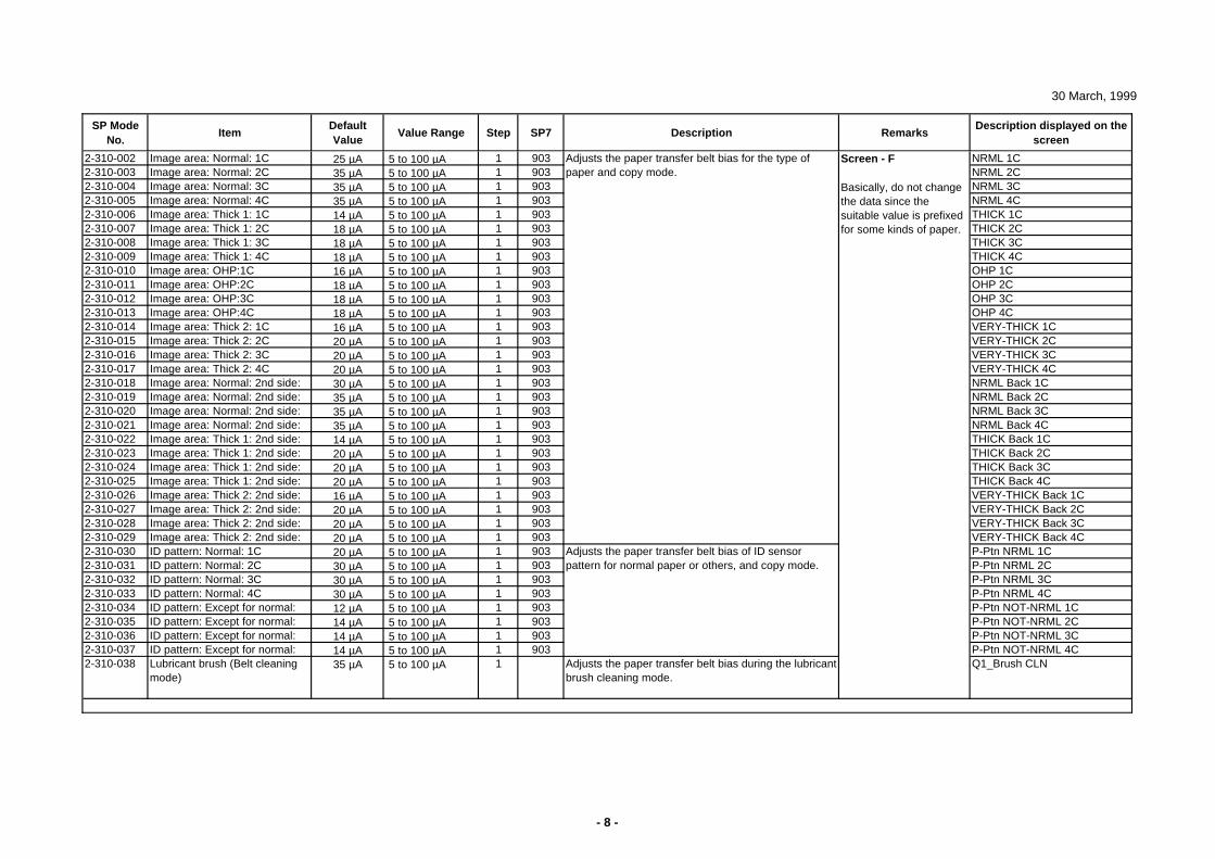
30 March, 1999
SP Mode No.
ItemDefault Value
Value Range Step SP7 Description RemarksDescription displayed on the
screen
2-310-002 Image area: Normal: 1C 25 µA 5 to 100 µA 1 903 NRML 1C2-310-003 Image area: Normal: 2C 35 µA 5 to 100 µA 1 903 NRML 2C2-310-004 Image area: Normal: 3C 35 µA 5 to 100 µA 1 903 NRML 3C2-310-005 Image area: Normal: 4C 35 µA 5 to 100 µA 1 903 NRML 4C2-310-006 Image area: Thick 1: 1C 14 µA 5 to 100 µA 1 903 THICK 1C2-310-007 Image area: Thick 1: 2C 18 µA 5 to 100 µA 1 903 THICK 2C2-310-008 Image area: Thick 1: 3C 18 µA 5 to 100 µA 1 903 THICK 3C2-310-009 Image area: Thick 1: 4C 18 µA 5 to 100 µA 1 903 THICK 4C2-310-010 Image area: OHP:1C 16 µA 5 to 100 µA 1 903 OHP 1C2-310-011 Image area: OHP:2C 18 µA 5 to 100 µA 1 903 OHP 2C2-310-012 Image area: OHP:3C 18 µA 5 to 100 µA 1 903 OHP 3C2-310-013 Image area: OHP:4C 18 µA 5 to 100 µA 1 903 OHP 4C2-310-014 Image area: Thick 2: 1C 16 µA 5 to 100 µA 1 903 VERY-THICK 1C2-310-015 Image area: Thick 2: 2C 20 µA 5 to 100 µA 1 903 VERY-THICK 2C2-310-016 Image area: Thick 2: 3C 20 µA 5 to 100 µA 1 903 VERY-THICK 3C2-310-017 Image area: Thick 2: 4C 20 µA 5 to 100 µA 1 903 VERY-THICK 4C2-310-018 Image area: Normal: 2nd side: 30 µA 5 to 100 µA 1 903 NRML Back 1C2-310-019 Image area: Normal: 2nd side: 35 µA 5 to 100 µA 1 903 NRML Back 2C2-310-020 Image area: Normal: 2nd side: 35 µA 5 to 100 µA 1 903 NRML Back 3C2-310-021 Image area: Normal: 2nd side: 35 µA 5 to 100 µA 1 903 NRML Back 4C2-310-022 Image area: Thick 1: 2nd side: 14 µA 5 to 100 µA 1 903 THICK Back 1C2-310-023 Image area: Thick 1: 2nd side: 20 µA 5 to 100 µA 1 903 THICK Back 2C2-310-024 Image area: Thick 1: 2nd side: 20 µA 5 to 100 µA 1 903 THICK Back 3C2-310-025 Image area: Thick 1: 2nd side: 20 µA 5 to 100 µA 1 903 THICK Back 4C2-310-026 Image area: Thick 2: 2nd side: 16 µA 5 to 100 µA 1 903 VERY-THICK Back 1C2-310-027 Image area: Thick 2: 2nd side: 20 µA 5 to 100 µA 1 903 VERY-THICK Back 2C2-310-028 Image area: Thick 2: 2nd side: 20 µA 5 to 100 µA 1 903 VERY-THICK Back 3C2-310-029 Image area: Thick 2: 2nd side: 20 µA 5 to 100 µA 1 903 VERY-THICK Back 4C2-310-030 ID pattern: Normal: 1C 20 µA 5 to 100 µA 1 903 P-Ptn NRML 1C2-310-031 ID pattern: Normal: 2C 30 µA 5 to 100 µA 1 903 P-Ptn NRML 2C2-310-032 ID pattern: Normal: 3C 30 µA 5 to 100 µA 1 903 P-Ptn NRML 3C2-310-033 ID pattern: Normal: 4C 30 µA 5 to 100 µA 1 903 P-Ptn NRML 4C2-310-034 ID pattern: Except for normal: 12 µA 5 to 100 µA 1 903 P-Ptn NOT-NRML 1C2-310-035 ID pattern: Except for normal: 14 µA 5 to 100 µA 1 903 P-Ptn NOT-NRML 2C2-310-036 ID pattern: Except for normal: 14 µA 5 to 100 µA 1 903 P-Ptn NOT-NRML 3C2-310-037 ID pattern: Except for normal: 14 µA 5 to 100 µA 1 903 P-Ptn NOT-NRML 4C2-310-038 Lubricant brush (Belt cleaning
mode)35 µA 5 to 100 µA 1 Adjusts the paper transfer belt bias during the lubricant
brush cleaning mode.Q1_Brush CLN
Adjusts the paper transfer belt bias for the type of paper and copy mode.
Screen - F
Basically, do not change the data since the suitable value is prefixed for some kinds of paper.
Adjusts the paper transfer belt bias of ID sensor pattern for normal paper or others, and copy mode.
- 8 -
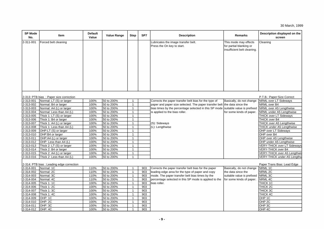
30 March, 1999
SP Mode No.
ItemDefault Value
Value Range Step SP7 Description RemarksDescription displayed on the
screen
2-311-001 Forced belt cleaning Lubricates the image transfer belt.Press the On key to start.
This mode may effects for partial blanking or insufficient belt cleaning.
Cleaning
2-313: PTB bias : Paper size correction P.T.B.: Paper:Size Correct2-313-001 Normal: LT (S) or larger 100% 50 to 200% 1 NRML over LT Sideways2-313-002 Normal: B4 or larger 100% 50 to 200% 1 NRML over B42-313-003 Normal: A4 (L) or larger 100% 50 to 200% 1 NRML over A5 Lengthwise2-313-004 Normal: Less than A4 (L) 100% 50 to 200% 1 NRML under A5 Lengthwise2-313-005 Thick 1: LT (S) or larger 100% 50 to 200% 1 THICK over LT Sideways2-313-006 Thick 1: B4 or larger 100% 50 to 200% 1 THICK over B42-313-007 Thick 1: A4 (L) or larger 100% 50 to 200% 1 THICK over A5 Lengthwise2-313-008 Thick 1: Less than A4 (L) 100% 50 to 200% 1 THICK under A5 Lengthwise2-313-009 OHP:LT (S) or larger 100% 50 to 200% 1 OHP over LT Sideways2-313-010 OHP:B4 or larger 100% 50 to 200% 1 OHP over B42-313-011 OHP:A4 (L) or larger 100% 50 to 200% 1 OHP over A5 Lengthwise2-313-012 OHP: Less than A4 (L) 100% 50 to 200% 1 OHP under A5 Lengthwise2-313-013 Thick 2: LT (S) or larger 100% 50 to 200% 1 VERY-THICK over LT Sideways2-313-014 Thick 2: B4 or larger 100% 50 to 200% 1 VERY-THICK over B42-313-015 Thick 2: A4 (L) or larger 100% 50 to 200% 1 VERY-THICK over A5 Lengthwis2-313-016 Thick 2: Less than A4 (L) 100% 50 to 200% 1 VERY-THICK under A5 Lengthw
2-314: PTB bias : Leading edge correction Paper Trans Bias: Lead Edge2-314-001 Normal: 1C 110% 50 to 200% 1 903 NRML 1C2-314-002 Normal: 2C 110% 50 to 200% 1 903 NRML 2C2-314-003 Normal: 3C 110% 50 to 200% 1 903 NRML 3C2-314-004 Normal: 4C 110% 50 to 200% 1 903 NRML 4C2-314-005 Thick 1: 1C 100% 50 to 200% 1 903 THICK 1C2-314-006 Thick 1: 2C 100% 50 to 200% 1 903 THICK 2C2-314-007 Thick 1: 3C 100% 50 to 200% 1 903 THICK 3C2-314-008 Thick 1: 4C 100% 50 to 200% 1 903 THICK 4C2-314-009 OHP: 1C 100% 50 to 200% 1 903 OHP 1C2-314-010 OHP: 2C 100% 50 to 200% 1 903 OHP 2C2-314-011 OHP: 3C 100% 50 to 200% 1 903 OHP 3C2-314-012 OHP: 4C 100% 50 to 200% 1 903 OHP 4C
Corrects the paper transfer belt bias for the paper leading edge area for the type of paper and copy mode. The paper transfer belt bias times by the percentage selected in this SP mode is applied to the bias roller.
Corrects the paper transfer belt bias for the type of paper and paper size selected. The paper transfer belt bias times by the percentage selected in this SP mode is applied to the bias roller.
(S): Sideways(L): Lengthwise
Basically, do not change the data since the suitable value is prefixed for some kinds of paper.
Basically, do not change the data since the suitable value is prefixed for some kinds of paper.
- 9 -
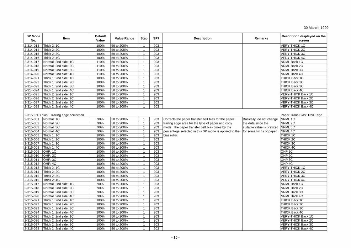
30 March, 1999
SP Mode No.
ItemDefault Value
Value Range Step SP7 Description RemarksDescription displayed on the
screen
2-314-013 Thick 2: 1C 100% 50 to 200% 1 903 VERY-THICK 1C2-314-014 Thick 2: 2C 100% 50 to 200% 1 903 VERY-THICK 2C2-314-015 Thick 2: 3C 100% 50 to 200% 1 903 VERY-THICK 3C2-314-016 Thick 2: 4C 100% 50 to 200% 1 903 VERY-THICK 4C2-314-017 Normal: 2nd side: 1C 110% 50 to 200% 1 903 NRML Back 1C2-314-018 Normal: 2nd side: 2C 110% 50 to 200% 1 903 NRML Back 2C2-314-019 Normal: 2nd side: 3C 110% 50 to 200% 1 903 NRML Back 3C2-314-020 Normal: 2nd side: 4C 110% 50 to 200% 1 903 NRML Back 4C2-314-021 Thick 1: 2nd side: 1C 100% 50 to 200% 1 903 THICK Back 1C2-314-022 Thick 1: 2nd side: 2C 100% 50 to 200% 1 903 THICK Back 2C2-314-023 Thick 1: 2nd side: 3C 100% 50 to 200% 1 903 THICK Back 3C2-314-024 Thick 1: 2nd side: 4C 100% 50 to 200% 1 903 THICK Back 4C2-314-025 Thick 2: 2nd side: 1C 100% 50 to 200% 1 903 VERY-THICK Back 1C2-314-026 Thick 2: 2nd side: 2C 100% 50 to 200% 1 903 VERY-THICK Back 2C2-314-027 Thick 2: 2nd side: 3C 100% 50 to 200% 1 903 VERY-THICK Back 3C2-314-028 Thick 2: 2nd side: 4C 100% 50 to 200% 1 903 VERY-THICK Back 4C
2-315: PTB bias : Trailing edge correction Paper Trans Bias: Trail Edge2-315-001 Normal: 1C 90% 50 to 200% 1 903 NRML 1C2-315-002 Normal: 2C 90% 50 to 200% 1 903 NRML 2C2-315-003 Normal: 3C 90% 50 to 200% 1 903 NRML 3C2-315-004 Normal: 4C 90% 50 to 200% 1 903 NRML 4C2-315-005 Thick 1: 1C 100% 50 to 200% 1 903 THICK 1C2-315-006 Thick 1: 2C 100% 50 to 200% 1 903 THICK 2C2-315-007 Thick 1: 3C 100% 50 to 200% 1 903 THICK 3C2-315-008 Thick 1: 4C 100% 50 to 200% 1 903 THICK 4C2-315-009 OHP: 1C 100% 50 to 200% 1 903 OHP 1C2-315-010 OHP: 2C 100% 50 to 200% 1 903 OHP 2C2-315-011 OHP: 3C 100% 50 to 200% 1 903 OHP 3C2-315-012 OHP: 4C 100% 50 to 200% 1 903 OHP 4C2-315-013 Thick 2: 1C 100% 50 to 200% 1 903 VERY-THICK 1C2-315-014 Thick 2: 2C 100% 50 to 200% 1 903 VERY-THICK 2C2-315-015 Thick 2: 3C 100% 50 to 200% 1 903 VERY-THICK 3C2-315-016 Thick 2: 4C 100% 50 to 200% 1 903 VERY-THICK 4C2-315-017 Normal: 2nd side: 1C 90% 50 to 200% 1 903 NRML Back 1C2-315-018 Normal: 2nd side: 2C 90% 50 to 200% 1 903 NRML Back 2C2-315-019 Normal: 2nd side: 3C 90% 50 to 200% 1 903 NRML Back 3C2-315-020 Normal: 2nd side: 4C 90% 50 to 200% 1 903 NRML Back 4C2-315-021 Thick 1: 2nd side: 1C 100% 50 to 200% 1 903 THICK Back 1C2-315-022 Thick 1: 2nd side: 2C 100% 50 to 200% 1 903 THICK Back 2C2-315-023 Thick 1: 2nd side: 3C 100% 50 to 200% 1 903 THICK Back 3C2-315-024 Thick 1: 2nd side: 4C 100% 50 to 200% 1 903 THICK Back 4C2-315-025 Thick 2: 2nd side: 1C 100% 50 to 200% 1 903 VERY-THICK Back 1C2-315-026 Thick 2: 2nd side: 2C 100% 50 to 200% 1 903 VERY-THICK Back 2C2-315-027 Thick 2: 2nd side: 3C 100% 50 to 200% 1 903 VERY-THICK Back 3C2-315-028 Thick 2: 2nd side: 4C 100% 50 to 200% 1 903 VERY-THICK Back 4C
Basically, do not change the data since the suitable value is prefixed for some kinds of paper.
Corrects the paper transfer belt bias for the paper trailing edge area for the type of paper and copy mode. The paper transfer belt bias times by the percentage selected in this SP mode is applied to the bias roller.
- 10 -
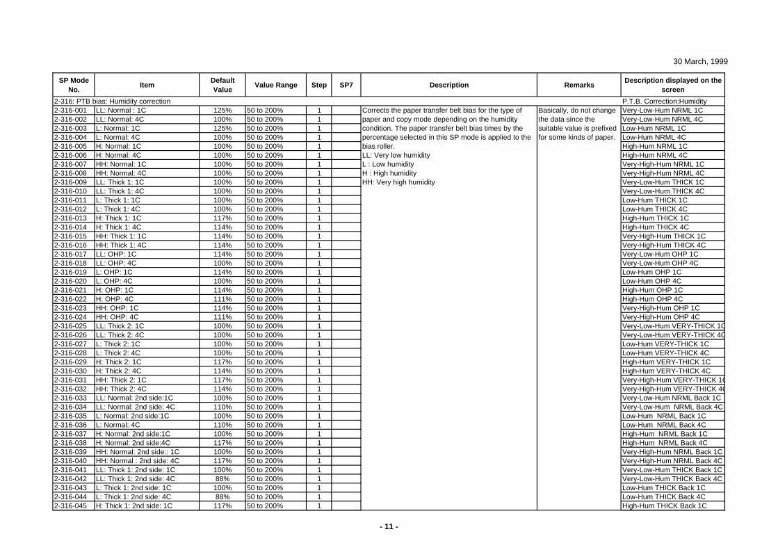
30 March, 1999
SP Mode No.
ItemDefault Value
Value Range Step SP7 Description RemarksDescription displayed on the
screen
2-316: PTB bias: Humidity correction P.T.B. Correction:Humidity2-316-001 LL: Normal : 1C 125% 50 to 200% 1 Very-Low-Hum NRML 1C2-316-002 LL: Normal: 4C 100% 50 to 200% 1 Very-Low-Hum NRML 4C2-316-003 L: Normal: 1C 125% 50 to 200% 1 Low-Hum NRML 1C2-316-004 L: Normal: 4C 100% 50 to 200% 1 Low-Hum NRML 4C2-316-005 H: Normal: 1C 100% 50 to 200% 1 High-Hum NRML 1C2-316-006 H: Normal: 4C 100% 50 to 200% 1 High-Hum NRML 4C2-316-007 HH: Normal: 1C 100% 50 to 200% 1 Very-High-Hum NRML 1C2-316-008 HH: Normal: 4C 100% 50 to 200% 1 Very-High-Hum NRML 4C2-316-009 LL: Thick 1: 1C 100% 50 to 200% 1 Very-Low-Hum THICK 1C2-316-010 LL: Thick 1: 4C 100% 50 to 200% 1 Very-Low-Hum THICK 4C2-316-011 L: Thick 1: 1C 100% 50 to 200% 1 Low-Hum THICK 1C2-316-012 L: Thick 1: 4C 100% 50 to 200% 1 Low-Hum THICK 4C2-316-013 H: Thick 1: 1C 117% 50 to 200% 1 High-Hum THICK 1C2-316-014 H: Thick 1: 4C 114% 50 to 200% 1 High-Hum THICK 4C2-316-015 HH: Thick 1: 1C 114% 50 to 200% 1 Very-High-Hum THICK 1C2-316-016 HH: Thick 1: 4C 114% 50 to 200% 1 Very-High-Hum THICK 4C2-316-017 LL: OHP: 1C 114% 50 to 200% 1 Very-Low-Hum OHP 1C2-316-018 LL: OHP: 4C 100% 50 to 200% 1 Very-Low-Hum OHP 4C2-316-019 L: OHP: 1C 114% 50 to 200% 1 Low-Hum OHP 1C2-316-020 L: OHP: 4C 100% 50 to 200% 1 Low-Hum OHP 4C2-316-021 H: OHP: 1C 114% 50 to 200% 1 High-Hum OHP 1C2-316-022 H: OHP: 4C 111% 50 to 200% 1 High-Hum OHP 4C2-316-023 HH: OHP: 1C 114% 50 to 200% 1 Very-High-Hum OHP 1C2-316-024 HH: OHP: 4C 111% 50 to 200% 1 Very-High-Hum OHP 4C2-316-025 LL: Thick 2: 1C 100% 50 to 200% 1 Very-Low-Hum VERY-THICK 1C2-316-026 LL: Thick 2: 4C 100% 50 to 200% 1 Very-Low-Hum VERY-THICK 4C2-316-027 L: Thick 2: 1C 100% 50 to 200% 1 Low-Hum VERY-THICK 1C2-316-028 L: Thick 2: 4C 100% 50 to 200% 1 Low-Hum VERY-THICK 4C2-316-029 H: Thick 2: 1C 117% 50 to 200% 1 High-Hum VERY-THICK 1C2-316-030 H: Thick 2: 4C 114% 50 to 200% 1 High-Hum VERY-THICK 4C2-316-031 HH: Thick 2: 1C 117% 50 to 200% 1 Very-High-Hum VERY-THICK 1C2-316-032 HH: Thick 2: 4C 114% 50 to 200% 1 Very-High-Hum VERY-THICK 4C2-316-033 LL: Normal: 2nd side:1C 100% 50 to 200% 1 Very-Low-Hum NRML Back 1C2-316-034 LL: Normal: 2nd side: 4C 110% 50 to 200% 1 Very-Low-Hum NRML Back 4C2-316-035 L: Normal: 2nd side:1C 100% 50 to 200% 1 Low-Hum NRML Back 1C2-316-036 L: Normal: 4C 110% 50 to 200% 1 Low-Hum NRML Back 4C2-316-037 H: Normal: 2nd side:1C 100% 50 to 200% 1 High-Hum NRML Back 1C2-316-038 H: Normal: 2nd side:4C 117% 50 to 200% 1 High-Hum NRML Back 4C2-316-039 HH: Normal: 2nd side:: 1C 100% 50 to 200% 1 Very-High-Hum NRML Back 1C2-316-040 HH: Normal : 2nd side: 4C 117% 50 to 200% 1 Very-High-Hum NRML Back 4C2-316-041 LL: Thick 1: 2nd side: 1C 100% 50 to 200% 1 Very-Low-Hum THICK Back 1C2-316-042 LL: Thick 1: 2nd side: 4C 88% 50 to 200% 1 Very-Low-Hum THICK Back 4C2-316-043 L: Thick 1: 2nd side: 1C 100% 50 to 200% 1 Low-Hum THICK Back 1C2-316-044 L: Thick 1: 2nd side: 4C 88% 50 to 200% 1 Low-Hum THICK Back 4C2-316-045 H: Thick 1: 2nd side: 1C 117% 50 to 200% 1 High-Hum THICK Back 1C
Basically, do not change the data since the suitable value is prefixed for some kinds of paper.
Corrects the paper transfer belt bias for the type of paper and copy mode depending on the humidity condition. The paper transfer belt bias times by the percentage selected in this SP mode is applied to the bias roller.LL: Very low humidityL : Low humidityH : High humidityHH: Very high humidity
- 11 -
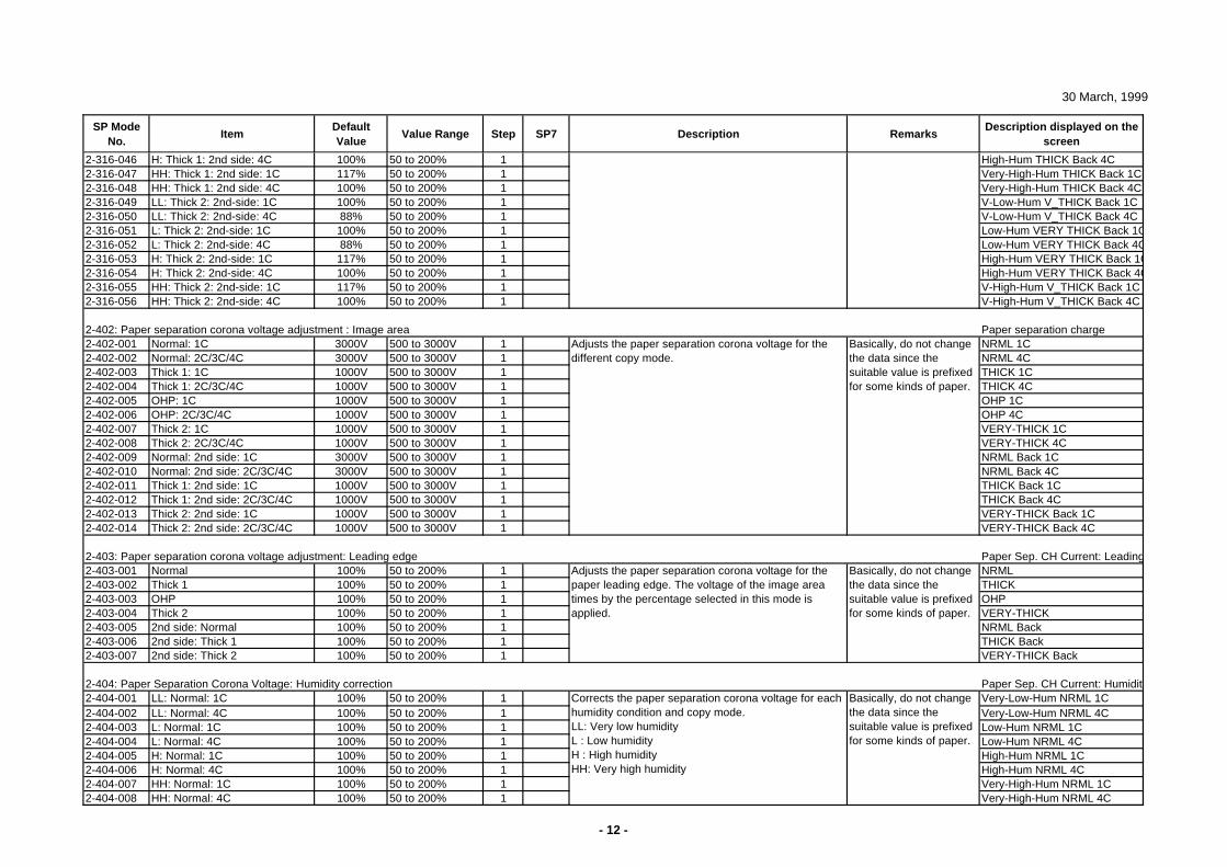
30 March, 1999
SP Mode No.
ItemDefault Value
Value Range Step SP7 Description RemarksDescription displayed on the
screen
2-316-046 H: Thick 1: 2nd side: 4C 100% 50 to 200% 1 High-Hum THICK Back 4C2-316-047 HH: Thick 1: 2nd side: 1C 117% 50 to 200% 1 Very-High-Hum THICK Back 1C2-316-048 HH: Thick 1: 2nd side: 4C 100% 50 to 200% 1 Very-High-Hum THICK Back 4C2-316-049 LL: Thick 2: 2nd-side: 1C 100% 50 to 200% 1 V-Low-Hum V_THICK Back 1C2-316-050 LL: Thick 2: 2nd-side: 4C 88% 50 to 200% 1 V-Low-Hum V_THICK Back 4C2-316-051 L: Thick 2: 2nd-side: 1C 100% 50 to 200% 1 Low-Hum VERY THICK Back 1C2-316-052 L: Thick 2: 2nd-side: 4C 88% 50 to 200% 1 Low-Hum VERY THICK Back 4C2-316-053 H: Thick 2: 2nd-side: 1C 117% 50 to 200% 1 High-Hum VERY THICK Back 1C2-316-054 H: Thick 2: 2nd-side: 4C 100% 50 to 200% 1 High-Hum VERY THICK Back 4C2-316-055 HH: Thick 2: 2nd-side: 1C 117% 50 to 200% 1 V-High-Hum V_THICK Back 1C2-316-056 HH: Thick 2: 2nd-side: 4C 100% 50 to 200% 1 V-High-Hum V_THICK Back 4C
2-402: Paper separation corona voltage adjustment : Image area Paper separation charge2-402-001 Normal: 1C 3000V 500 to 3000V 1 NRML 1C2-402-002 Normal: 2C/3C/4C 3000V 500 to 3000V 1 NRML 4C2-402-003 Thick 1: 1C 1000V 500 to 3000V 1 THICK 1C2-402-004 Thick 1: 2C/3C/4C 1000V 500 to 3000V 1 THICK 4C2-402-005 OHP: 1C 1000V 500 to 3000V 1 OHP 1C2-402-006 OHP: 2C/3C/4C 1000V 500 to 3000V 1 OHP 4C2-402-007 Thick 2: 1C 1000V 500 to 3000V 1 VERY-THICK 1C2-402-008 Thick 2: 2C/3C/4C 1000V 500 to 3000V 1 VERY-THICK 4C2-402-009 Normal: 2nd side: 1C 3000V 500 to 3000V 1 NRML Back 1C2-402-010 Normal: 2nd side: 2C/3C/4C 3000V 500 to 3000V 1 NRML Back 4C2-402-011 Thick 1: 2nd side: 1C 1000V 500 to 3000V 1 THICK Back 1C2-402-012 Thick 1: 2nd side: 2C/3C/4C 1000V 500 to 3000V 1 THICK Back 4C2-402-013 Thick 2: 2nd side: 1C 1000V 500 to 3000V 1 VERY-THICK Back 1C2-402-014 Thick 2: 2nd side: 2C/3C/4C 1000V 500 to 3000V 1 VERY-THICK Back 4C
2-403: Paper separation corona voltage adjustment: Leading edge Paper Sep. CH Current: Leading2-403-001 Normal 100% 50 to 200% 1 NRML2-403-002 Thick 1 100% 50 to 200% 1 THICK2-403-003 OHP 100% 50 to 200% 1 OHP2-403-004 Thick 2 100% 50 to 200% 1 VERY-THICK2-403-005 2nd side: Normal 100% 50 to 200% 1 NRML Back2-403-006 2nd side: Thick 1 100% 50 to 200% 1 THICK Back2-403-007 2nd side: Thick 2 100% 50 to 200% 1 VERY-THICK Back
2-404: Paper Separation Corona Voltage: Humidity correction Paper Sep. CH Current: Humidity2-404-001 LL: Normal: 1C 100% 50 to 200% 1 Very-Low-Hum NRML 1C2-404-002 LL: Normal: 4C 100% 50 to 200% 1 Very-Low-Hum NRML 4C2-404-003 L: Normal: 1C 100% 50 to 200% 1 Low-Hum NRML 1C2-404-004 L: Normal: 4C 100% 50 to 200% 1 Low-Hum NRML 4C2-404-005 H: Normal: 1C 100% 50 to 200% 1 High-Hum NRML 1C2-404-006 H: Normal: 4C 100% 50 to 200% 1 High-Hum NRML 4C2-404-007 HH: Normal: 1C 100% 50 to 200% 1 Very-High-Hum NRML 1C2-404-008 HH: Normal: 4C 100% 50 to 200% 1 Very-High-Hum NRML 4C
Basically, do not change the data since the suitable value is prefixed for some kinds of paper.
Basically, do not change the data since the suitable value is prefixed for some kinds of paper.
Basically, do not change the data since the suitable value is prefixed for some kinds of paper.
Adjusts the paper separation corona voltage for the paper leading edge. The voltage of the image area times by the percentage selected in this mode is applied.
Corrects the paper separation corona voltage for each humidity condition and copy mode. LL: Very low humidityL : Low humidityH : High humidityHH: Very high humidity
Adjusts the paper separation corona voltage for the different copy mode.
- 12 -
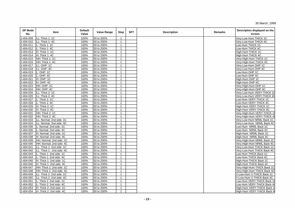
30 March, 1999
SP Mode No.
ItemDefault Value
Value Range Step SP7 Description RemarksDescription displayed on the
screen
2-404-009 LL: Thick 1: 1C 100% 50 to 200% 1 Very-Low-Hum THICK 1C2-404-010 LL: Thick 1: 4C 100% 50 to 200% 1 Very-Low-Hum THICK 4C2-404-011 L: Thick 1: 1C 100% 50 to 200% 1 Low-Hum THICK 1C2-404-012 L: Thick 1: 4C 100% 50 to 200% 1 Low-Hum THICK 4C2-404-013 H: Thick 1: 1C 100% 50 to 200% 1 High-Hum THICK 1C2-404-014 H: Thick 1: 4C 100% 50 to 200% 1 High-Hum THICK 4C2-404-015 HH: Thick 1: 1C 100% 50 to 200% 1 Very-High-Hum THICK 1C2-404-016 HH: Thick 1: 4C 100% 50 to 200% 1 Very-High-Hum THICK 4C2-404-017 LL: OHP: 1C 100% 50 to 200% 1 Very-Low-Hum OHP 1C2-404-018 LL: OHP: 4C 100% 50 to 200% 1 Very-Low-Hum OHP 4C2-404-019 L: OHP: 1C 100% 50 to 200% 1 Low-Hum OHP 1C2-404-020 L: OHP: 4C 100% 50 to 200% 1 Low-Hum OHP 4C2-404-021 H: OHP: 1C 100% 50 to 200% 1 High-Hum OHP 1C2-404-022 H: OHP: 4C 100% 50 to 200% 1 High-Hum OHP 4C2-404-023 HH: OHP: 1C 100% 50 to 200% 1 Very-High-Hum OHP 1C2-404-024 HH: OHP: 4C 100% 50 to 200% 1 Very-High-Hum OHP 4C2-404-025 LL: Thick 2: 1C 100% 50 to 200% 1 Very-Low-Hum VERY-THICK 1C2-404-026 LL: Thick 2: 4C 100% 50 to 200% 1 Very-Low-Hum VERY-THICK 4C2-404-027 L: Thick 2: 1C 100% 50 to 200% 1 Low-Hum VERY-THICK 1C2-404-028 L: Thick 2: 4C 100% 50 to 200% 1 Low-Hum VERY-THICK 4C2-404-029 H: Thick 2: 1C 100% 50 to 200% 1 High-Hum VERY-THICK 1C2-404-030 H: Thick 2: 4C 100% 50 to 200% 1 High-Hum VERY-THICK 4C2-404-031 HH: Thick 2: 1C 100% 50 to 200% 1 Very-High-Hum VERY-THICK 1C2-404-032 HH: Thick 2: 4C 100% 50 to 200% 1 Very-High-Hum VERY-THICK 4C2-404-033 LL: Normal: 2nd side: 1C 100% 50 to 200% 1 Very-Low-Hum NRML Back 1C2-404-034 LL: Normal: 2nd side: 4C 100% 50 to 200% 1 Very-Low-Hum NRML Back 4C2-404-035 L: Normal: 2nd side: 1C 100% 50 to 200% 1 Low-Hum NRML Back 1C2-404-036 L: Normal: 2nd side: 4C 100% 50 to 200% 1 Low-Hum NRML Back 4C2-404-037 H: Normal: 2nd side: 1C 100% 50 to 200% 1 High-Hum NRML Back 1C2-404-038 H: Normal: 2nd side: 4C 100% 50 to 200% 1 High-Hum NRML Back 4C2-404-039 HH: Normal: 2nd side: 1C 100% 50 to 200% 1 Very-High-Hum NRML Back 1C2-404-040 HH: Normal: 2nd side: 4C 100% 50 to 200% 1 Very-High-Hum NRML Back 4C2-404-041 LL: Thick 1: 2nd side: 1C 100% 50 to 200% 1 Very-Low-Hum THICK Back 1C2-404-042 LL: Thick 1 : 2nd side: 4C 100% 50 to 200% 1 Very-Low-Hum THICK Back 4C2-404-043 L: Thick 1: 2nd side: 1C 100% 50 to 200% 1 Low-Hum THICK Back 1C2-404-044 L: Thick 1: 2nd side: 4C 100% 50 to 200% 1 Low-Hum THICK Back 4C2-404-045 H: Thick 1: 2nd side: 1C 100% 50 to 200% 1 High-Hum THICK Back 1C2-404-046 H: Thick 1: 2nd side: 4C 100% 50 to 200% 1 High-Hum THICK Back 4C2-404-047 HH: Thick 1: 2nd side: 1C 100% 50 to 200% 1 Very-High-Hum THICK Back 1C2-404-048 HH: Thick 1: 2nd side: 4C 100% 50 to 200% 1 Very-High-Hum THICK Back 4C2-404-049 LL: Thick 2: 2nd side: 1C 100% 50 to 200% 1 V-Low-Hum V-THICK Back 1C2-404-050 LL: Thick 2: 2nd side: 4C 100% 50 to 200% 1 V-Low-Hum V-THICK Back 4C2-404-051 L: Thick 2: 2nd side: 1C 100% 50 to 200% 1 Low-Hum VERY-THICK Back 1C2-404-052 L: Thick 2: 2nd side: 4C 100% 50 to 200% 1 Low-Hum VERY-THICK Back 4C2-404-053 H: Thick 2: 2nd side: 1C 100% 50 to 200% 1 High-Hum VERY-THICK Back 1C2-404-054 H: Thick 2: 2nd side: 4C 100% 50 to 200% 1 High-Hum VERY-THICK Back 4C
- 13 -
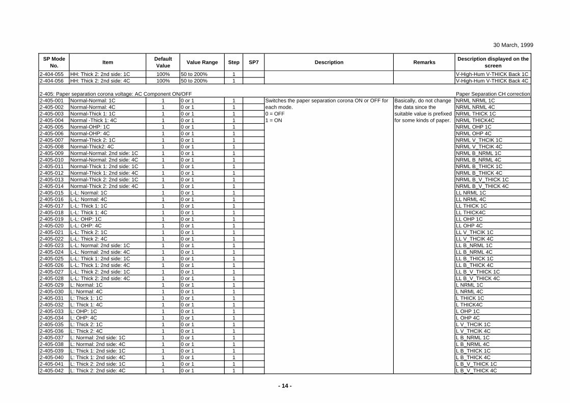
30 March, 1999
SP Mode No.
ItemDefault Value
Value Range Step SP7 Description RemarksDescription displayed on the
screen
2-404-055 HH: Thick 2: 2nd side: 1C 100% 50 to 200% 1 V-High-Hum V-THICK Back 1C2-404-056 HH: Thick 2: 2nd side: 4C 100% 50 to 200% 1 V-High-Hum V-THICK Back 4C
2-405: Paper separation corona voltage: AC Component ON/OFF Paper Separation CH correction:2-405-001 Normal-Normal: 1C 1 0 or 1 1 NRML NRML 1C2-405-002 Normal-Normal: 4C 1 0 or 1 1 NRML NRML 4C2-405-003 Normal-Thick 1: 1C 1 0 or 1 1 NRML THICK 1C2-405-004 Normal -Thick 1: 4C 1 0 or 1 1 NRML THICK4C2-405-005 Normal-OHP: 1C 1 0 or 1 1 NRML OHP 1C2-405-006 Normal-OHP: 4C 1 0 or 1 1 NRML OHP 4C2-405-007 Normal-Thick 2: 1C 1 0 or 1 1 NRML V_THCIK 1C2-405-008 Normal-Thick2: 4C 1 0 or 1 1 NRML V_THCIK 4C2-405-009 Normal-Normal: 2nd side: 1C 1 0 or 1 1 NRML B_NRML 1C2-405-010 Normal-Normal: 2nd side: 4C 1 0 or 1 1 NRML B_NRML 4C2-405-011 Normal-Thick 1: 2nd side: 1C 1 0 or 1 1 NRML B_THICK 1C2-405-012 Normal-Thick 1: 2nd side: 4C 1 0 or 1 1 NRML B_THICK 4C2-405-013 Normal-Thick 2: 2nd side: 1C 1 0 or 1 1 NRML B_V_THICK 1C2-405-014 Normal-Thick 2: 2nd side: 4C 1 0 or 1 1 NRML B_V_THICK 4C2-405-015 L-L: Normal: 1C 1 0 or 1 1 LL NRML 1C2-405-016 L-L: Normal: 4C 1 0 or 1 1 LL NRML 4C2-405-017 L-L: Thick 1: 1C 1 0 or 1 1 LL THICK 1C2-405-018 L-L: Thick 1: 4C 1 0 or 1 1 LL THICK4C2-405-019 L-L: OHP: 1C 1 0 or 1 1 LL OHP 1C2-405-020 L-L: OHP: 4C 1 0 or 1 1 LL OHP 4C2-405-021 L-L: Thick 2: 1C 1 0 or 1 1 LL V_THCIK 1C2-405-022 L-L: Thick 2: 4C 1 0 or 1 1 LL V_THCIK 4C2-405-023 L-L: Normal: 2nd side: 1C 1 0 or 1 1 LL B_NRML 1C2-405-024 L-L: Normal: 2nd side: 4C 1 0 or 1 1 LL B_NRML 4C2-405-025 L-L: Thick 1: 2nd side: 1C 1 0 or 1 1 LL B_THICK 1C2-405-026 L-L: Thick 1: 2nd side: 4C 1 0 or 1 1 LL B_THICK 4C2-405-027 L-L: Thick 2: 2nd side: 1C 1 0 or 1 1 LL B_V_THICK 1C2-405-028 L-L: Thick 2: 2nd side: 4C 1 0 or 1 1 LL B_V_THICK 4C2-405-029 L: Normal: 1C 1 0 or 1 1 L NRML 1C2-405-030 L: Normal: 4C 1 0 or 1 1 L NRML 4C2-405-031 L: Thick 1: 1C 1 0 or 1 1 L THICK 1C2-405-032 L: Thick 1: 4C 1 0 or 1 1 L THICK4C2-405-033 L: OHP: 1C 1 0 or 1 1 L OHP 1C2-405-034 L: OHP: 4C 1 0 or 1 1 L OHP 4C2-405-035 L: Thick 2: 1C 1 0 or 1 1 L V_THCIK 1C2-405-036 L: Thick 2: 4C 1 0 or 1 1 L V_THCIK 4C2-405-037 L: Normal: 2nd side: 1C 1 0 or 1 1 L B_NRML 1C2-405-038 L: Normal: 2nd side: 4C 1 0 or 1 1 L B_NRML 4C2-405-039 L: Thick 1: 2nd side: 1C 1 0 or 1 1 L B_THICK 1C2-405-040 L: Thick 1: 2nd side: 4C 1 0 or 1 1 L B_THICK 4C2-405-041 L: Thick 2: 2nd side: 1C 1 0 or 1 1 L B_V_THICK 1C2-405-042 L: Thick 2: 2nd side: 4C 1 0 or 1 1 L B_V_THICK 4C
Basically, do not change the data since the suitable value is prefixed for some kinds of paper.
Switches the paper separation corona ON or OFF for each mode.0 = OFF1 = ON
- 14 -
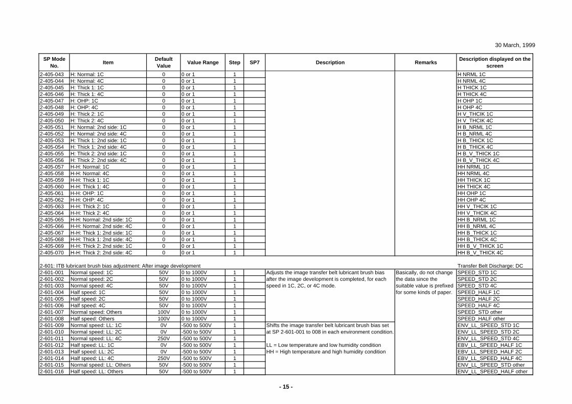
30 March, 1999
SP Mode No.
ItemDefault Value
Value Range Step SP7 Description RemarksDescription displayed on the
screen
2-405-043 H: Normal: 1C 0 0 or 1 1 H NRML 1C2-405-044 H: Normal: 4C 0 0 or 1 1 H NRML 4C2-405-045 H: Thick 1: 1C 0 0 or 1 1 H THICK 1C2-405-046 H: Thick 1: 4C 0 0 or 1 1 H THICK 4C2-405-047 H: OHP: 1C 0 0 or 1 1 H OHP 1C2-405-048 H: OHP: 4C 0 0 or 1 1 H OHP 4C2-405-049 H: Thick 2: 1C 0 0 or 1 1 H V_THCIK 1C2-405-050 H: Thick 2: 4C 0 0 or 1 1 H V_THCIK 4C2-405-051 H: Normal: 2nd side: 1C 0 0 or 1 1 H B_NRML 1C2-405-052 H: Normal: 2nd side: 4C 0 0 or 1 1 H B_NRML 4C2-405-053 H: Thick 1: 2nd side: 1C 0 0 or 1 1 H B_THICK 1C2-405-054 H: Thick 1: 2nd side: 4C 0 0 or 1 1 H B_THICK 4C2-405-055 H: Thick 2: 2nd side: 1C 0 0 or 1 1 H B_V_THICK 1C2-405-056 H: Thick 2: 2nd side: 4C 0 0 or 1 1 H B_V_THICK 4C2-405-057 H-H: Normal: 1C 0 0 or 1 1 HH NRML 1C2-405-058 H-H: Normal: 4C 0 0 or 1 1 HH NRML 4C2-405-059 H-H: Thick 1: 1C 0 0 or 1 1 HH THICK 1C2-405-060 H-H: Thick 1: 4C 0 0 or 1 1 HH THICK 4C2-405-061 H-H: OHP: 1C 0 0 or 1 1 HH OHP 1C2-405-062 H-H: OHP: 4C 0 0 or 1 1 HH OHP 4C2-405-063 H-H: Thick 2: 1C 0 0 or 1 1 HH V_THCIK 1C2-405-064 H-H: Thick 2: 4C 0 0 or 1 1 HH V_THCIK 4C2-405-065 H-H: Normal: 2nd side: 1C 0 0 or 1 1 HH B_NRML 1C2-405-066 H-H: Normal: 2nd side: 4C 0 0 or 1 1 HH B_NRML 4C2-405-067 H-H: Thick 1: 2nd side: 1C 0 0 or 1 1 HH B_THICK 1C2-405-068 H-H: Thick 1: 2nd side: 4C 0 0 or 1 1 HH B_THICK 4C2-405-069 H-H: Thick 2: 2nd side: 1C 0 0 or 1 1 HH B_V_THICK 1C2-405-070 H-H: Thick 2: 2nd side: 4C 0 0 or 1 1 HH B_V_THICK 4C
2-601: ITB lubricant brush bias adjustment: After image development Transfer Belt Discharge: DC2-601-001 Normal speed: 1C 50V 0 to 1000V 1 SPEED_STD 1C2-601-002 Normal speed: 2C 50V 0 to 1000V 1 SPEED_STD 2C2-601-003 Normal speed: 4C 50V 0 to 1000V 1 SPEED_STD 4C2-601-004 Half speed: 1C 50V 0 to 1000V 1 SPEED_HALF 1C2-601-005 Half speed: 2C 50V 0 to 1000V 1 SPEED_HALF 2C2-601-006 Half speed: 4C 50V 0 to 1000V 1 SPEED_HALF 4C2-601-007 Normal speed: Others 100V 0 to 1000V 1 SPEED_STD other2-601-008 Half speed: Others 100V 0 to 1000V 1 SPEED_HALF other2-601-009 Normal speed: LL: 1C 0V -500 to 500V 1 ENV_LL_SPEED_STD 1C2-601-010 Normal speed: LL: 2C 0V -500 to 500V 1 ENV_LL_SPEED_STD 2C2-601-011 Normal speed: LL: 4C 250V -500 to 500V 1 ENV_LL_SPEED_STD 4C2-601-012 Half speed: LL: 1C 0V -500 to 500V 1 EBV_LL_SPEED_HALF 1C2-601-013 Half speed: LL: 2C 0V -500 to 500V 1 EBV_LL_SPEED_HALF 2C2-601-014 Half speed: LL: 4C 250V -500 to 500V 1 EBV_LL_SPEED_HALF 4C2-601-015 Normal speed: LL: Others 50V -500 to 500V 1 ENV_LL_SPEED_STD other2-601-016 Half speed: LL: Others 50V -500 to 500V 1 ENV_LL_SPEED_HALF other
Adjusts the image transfer belt lubricant brush bias after the image development is completed, for each speed in 1C, 2C, or 4C mode.
Basically, do not change the data since the suitable value is prefixed for some kinds of paper.
Shifts the image transfer belt lubricant brush bias set at SP 2-601-001 to 008 in each environment condition.
LL = Low temperature and low humidity conditionHH = High temperature and high humidity condition
- 15 -
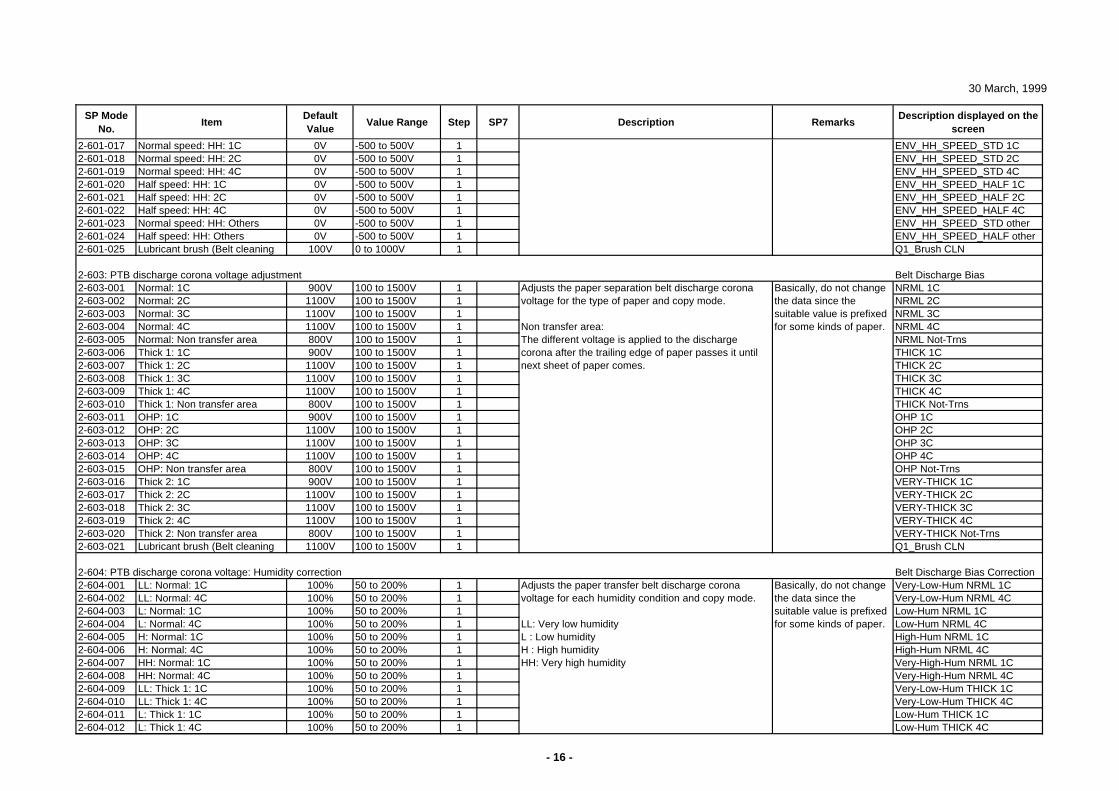
30 March, 1999
SP Mode No.
ItemDefault Value
Value Range Step SP7 Description RemarksDescription displayed on the
screen
2-601-017 Normal speed: HH: 1C 0V -500 to 500V 1 ENV_HH_SPEED_STD 1C2-601-018 Normal speed: HH: 2C 0V -500 to 500V 1 ENV_HH_SPEED_STD 2C2-601-019 Normal speed: HH: 4C 0V -500 to 500V 1 ENV_HH_SPEED_STD 4C2-601-020 Half speed: HH: 1C 0V -500 to 500V 1 ENV_HH_SPEED_HALF 1C2-601-021 Half speed: HH: 2C 0V -500 to 500V 1 ENV_HH_SPEED_HALF 2C2-601-022 Half speed: HH: 4C 0V -500 to 500V 1 ENV_HH_SPEED_HALF 4C2-601-023 Normal speed: HH: Others 0V -500 to 500V 1 ENV_HH_SPEED_STD other2-601-024 Half speed: HH: Others 0V -500 to 500V 1 ENV_HH_SPEED_HALF other2-601-025 Lubricant brush (Belt cleaning 100V 0 to 1000V 1 Q1_Brush CLN
2-603: PTB discharge corona voltage adjustment Belt Discharge Bias2-603-001 Normal: 1C 900V 100 to 1500V 1 NRML 1C2-603-002 Normal: 2C 1100V 100 to 1500V 1 NRML 2C2-603-003 Normal: 3C 1100V 100 to 1500V 1 NRML 3C2-603-004 Normal: 4C 1100V 100 to 1500V 1 NRML 4C2-603-005 Normal: Non transfer area 800V 100 to 1500V 1 NRML Not-Trns2-603-006 Thick 1: 1C 900V 100 to 1500V 1 THICK 1C2-603-007 Thick 1: 2C 1100V 100 to 1500V 1 THICK 2C2-603-008 Thick 1: 3C 1100V 100 to 1500V 1 THICK 3C2-603-009 Thick 1: 4C 1100V 100 to 1500V 1 THICK 4C2-603-010 Thick 1: Non transfer area 800V 100 to 1500V 1 THICK Not-Trns2-603-011 OHP: 1C 900V 100 to 1500V 1 OHP 1C2-603-012 OHP: 2C 1100V 100 to 1500V 1 OHP 2C2-603-013 OHP: 3C 1100V 100 to 1500V 1 OHP 3C2-603-014 OHP: 4C 1100V 100 to 1500V 1 OHP 4C2-603-015 OHP: Non transfer area 800V 100 to 1500V 1 OHP Not-Trns2-603-016 Thick 2: 1C 900V 100 to 1500V 1 VERY-THICK 1C2-603-017 Thick 2: 2C 1100V 100 to 1500V 1 VERY-THICK 2C2-603-018 Thick 2: 3C 1100V 100 to 1500V 1 VERY-THICK 3C2-603-019 Thick 2: 4C 1100V 100 to 1500V 1 VERY-THICK 4C2-603-020 Thick 2: Non transfer area 800V 100 to 1500V 1 VERY-THICK Not-Trns2-603-021 Lubricant brush (Belt cleaning 1100V 100 to 1500V 1 Q1_Brush CLN
2-604: PTB discharge corona voltage: Humidity correction Belt Discharge Bias Correction2-604-001 LL: Normal: 1C 100% 50 to 200% 1 Very-Low-Hum NRML 1C2-604-002 LL: Normal: 4C 100% 50 to 200% 1 Very-Low-Hum NRML 4C2-604-003 L: Normal: 1C 100% 50 to 200% 1 Low-Hum NRML 1C2-604-004 L: Normal: 4C 100% 50 to 200% 1 Low-Hum NRML 4C2-604-005 H: Normal: 1C 100% 50 to 200% 1 High-Hum NRML 1C2-604-006 H: Normal: 4C 100% 50 to 200% 1 High-Hum NRML 4C2-604-007 HH: Normal: 1C 100% 50 to 200% 1 Very-High-Hum NRML 1C2-604-008 HH: Normal: 4C 100% 50 to 200% 1 Very-High-Hum NRML 4C2-604-009 LL: Thick 1: 1C 100% 50 to 200% 1 Very-Low-Hum THICK 1C2-604-010 LL: Thick 1: 4C 100% 50 to 200% 1 Very-Low-Hum THICK 4C2-604-011 L: Thick 1: 1C 100% 50 to 200% 1 Low-Hum THICK 1C2-604-012 L: Thick 1: 4C 100% 50 to 200% 1 Low-Hum THICK 4C
Basically, do not change the data since the suitable value is prefixed for some kinds of paper.
Adjusts the paper transfer belt discharge corona voltage for each humidity condition and copy mode.
LL: Very low humidityL : Low humidityH : High humidityHH: Very high humidity
Basically, do not change the data since the suitable value is prefixed for some kinds of paper.
Adjusts the paper separation belt discharge corona voltage for the type of paper and copy mode.
Non transfer area:The different voltage is applied to the discharge corona after the trailing edge of paper passes it until next sheet of paper comes.
- 16 -
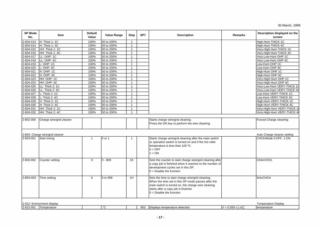
30 March, 1999
SP Mode No.
ItemDefault Value
Value Range Step SP7 Description RemarksDescription displayed on the
screen
2-604-013 H: Thick 1: 1C 100% 50 to 200% 1 High-Hum THICK 1C2-604-014 H: Thick 1: 4C 100% 50 to 200% 1 High-Hum THICK 4C2-604-015 HH: Thick 1: 1C 100% 50 to 200% 1 Very-High-Hum THICK 1C2-604-016 HH: Thick 1: 4C 100% 50 to 200% 1 Very-High-Hum THICK 4C2-604-017 LL: OHP: 1C 100% 50 to 200% 1 Very-Low-Hum OHP 1C2-604-018 LL: OHP: 4C 100% 50 to 200% 1 Very-Low-Hum OHP 4C2-604-019 L: OHP: 1C 100% 50 to 200% 1 Low-Hum OHP 1C2-604-020 L: OHP: 4C 100% 50 to 200% 1 Low-Hum OHP 4C2-604-021 H: OHP: 1C 100% 50 to 200% 1 High-Hum OHP 1C2-604-022 H: OHP: 4C 100% 50 to 200% 1 High-Hum OHP 4C2-604-023 HH: OHP: 1C 100% 50 to 200% 1 Very-High-Hum OHP 1C2-604-024 HH: OHP: 4C 100% 50 to 200% 1 Very-High-Hum OHP 4C2-604-025 LL: Thick 2: 1C 100% 50 to 200% 1 Very-Low-Hum VERY-THICK 1C2-604-026 LL: Thick 2: 4C 100% 50 to 200% 1 Very-Low-Hum VERY-THICK 4C2-604-027 L: Thick 2: 1C 100% 50 to 200% 1 Low-Hum VERY-THICK 1C2-604-028 L: Thick 2: 4C 100% 50 to 200% 1 Low-Hum VERY-THICK 4C2-604-029 H: Thick 2: 1C 100% 50 to 200% 1 High-Hum VERY-THICK 1C2-604-030 H: Thick 2: 4C 100% 50 to 200% 1 High-Hum VERY-THICK 4C2-604-031 HH: Thick 2: 1C 100% 50 to 200% 1 Very-High-Hum VERY-THICK 1C2-604-032 HH: Thick 2: 4C 100% 50 to 200% 1 Very-High-Hum VERY-THICK 4C
2-802-000 Charge wire/grid cleaner Starts charge wire/grid cleaning.Press the ON key to perform the wire cleaning.
Forced Charge cleaning
2-803: Charge wire/grid cleaner Auto Charge cleaner setting2-803-001 Start timing 1 0 or 1 1 Starts charge wire/grid cleaning after the main switch
or operation switch is turned on and if the hot roller temperature is less than 100 ºC.0 = OFF1 = ON
CHClnMode 0:OFF, 1:ON
2-803-002 Counter setting 0 0 - 80K 1K Sets the counter to start charge wire/grid cleaning after a copy job is finished when it reaches to the number of development cycles set in this SP.0 = Disable the function
ClntvCHCln
2-803-003 Time setting 0 0 to 999 1H Sets the time to start charge wire/grid cleaning.When the time set in this SP mode passes after the main switch is turned on, the charge wire cleaning starts after a copy job is finished.0 = Disable the function
tIntvCHCln
2-912: Environment display Temperature Display2-912-001 Temperature °C 903 Displays temperature detected. V = 0.050 x [ oC] temperature
- 17 -
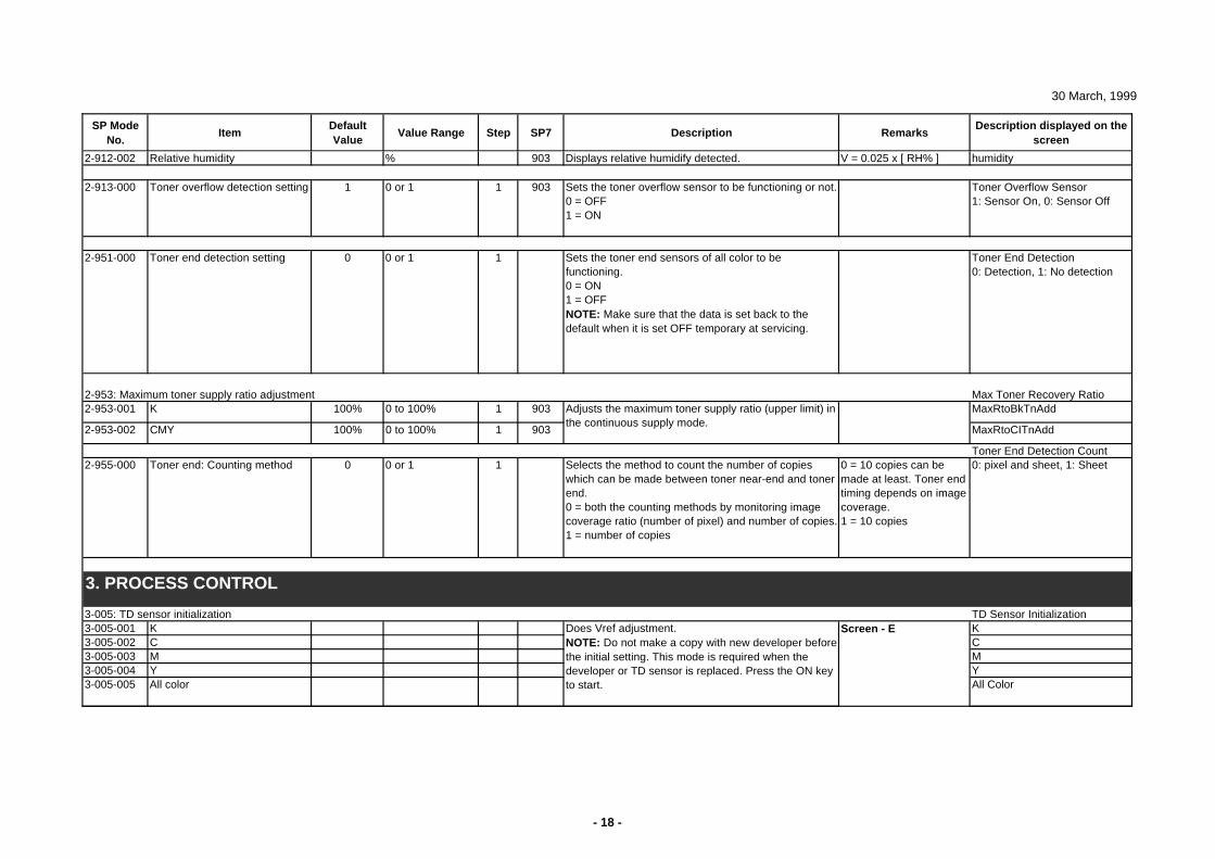
30 March, 1999
SP Mode No.
ItemDefault Value
Value Range Step SP7 Description RemarksDescription displayed on the
screen
2-912-002 Relative humidity % 903 Displays relative humidify detected. V = 0.025 x [ RH% ] humidity
2-913-000 Toner overflow detection setting 1 0 or 1 1 903 Sets the toner overflow sensor to be functioning or not.0 = OFF1 = ON
Toner Overflow Sensor1: Sensor On, 0: Sensor Off
2-951-000 Toner end detection setting 0 0 or 1 1 Sets the toner end sensors of all color to be functioning.0 = ON1 = OFFNOTE: Make sure that the data is set back to the default when it is set OFF temporary at servicing.
Toner End Detection0: Detection, 1: No detection
2-953: Maximum toner supply ratio adjustment Max Toner Recovery Ratio2-953-001 K 100% 0 to 100% 1 903 MaxRtoBkTnAdd
2-953-002 CMY 100% 0 to 100% 1 903 MaxRtoCITnAdd
Toner End Detection Count2-955-000 Toner end: Counting method 0 0 or 1 1 Selects the method to count the number of copies
which can be made between toner near-end and toner end.0 = both the counting methods by monitoring image coverage ratio (number of pixel) and number of copies.1 = number of copies
0 = 10 copies can be made at least. Toner end timing depends on image coverage.1 = 10 copies
0: pixel and sheet, 1: Sheet
3-005: TD sensor initialization TD Sensor Initialization3-005-001 K K3-005-002 C C3-005-003 M M3-005-004 Y Y3-005-005 All color All Color
Screen - E
Adjusts the maximum toner supply ratio (upper limit) in the continuous supply mode.
Does Vref adjustment. NOTE: Do not make a copy with new developer before the initial setting. This mode is required when the developer or TD sensor is replaced. Press the ON key to start.
3. PROCESS CONTROL
- 18 -
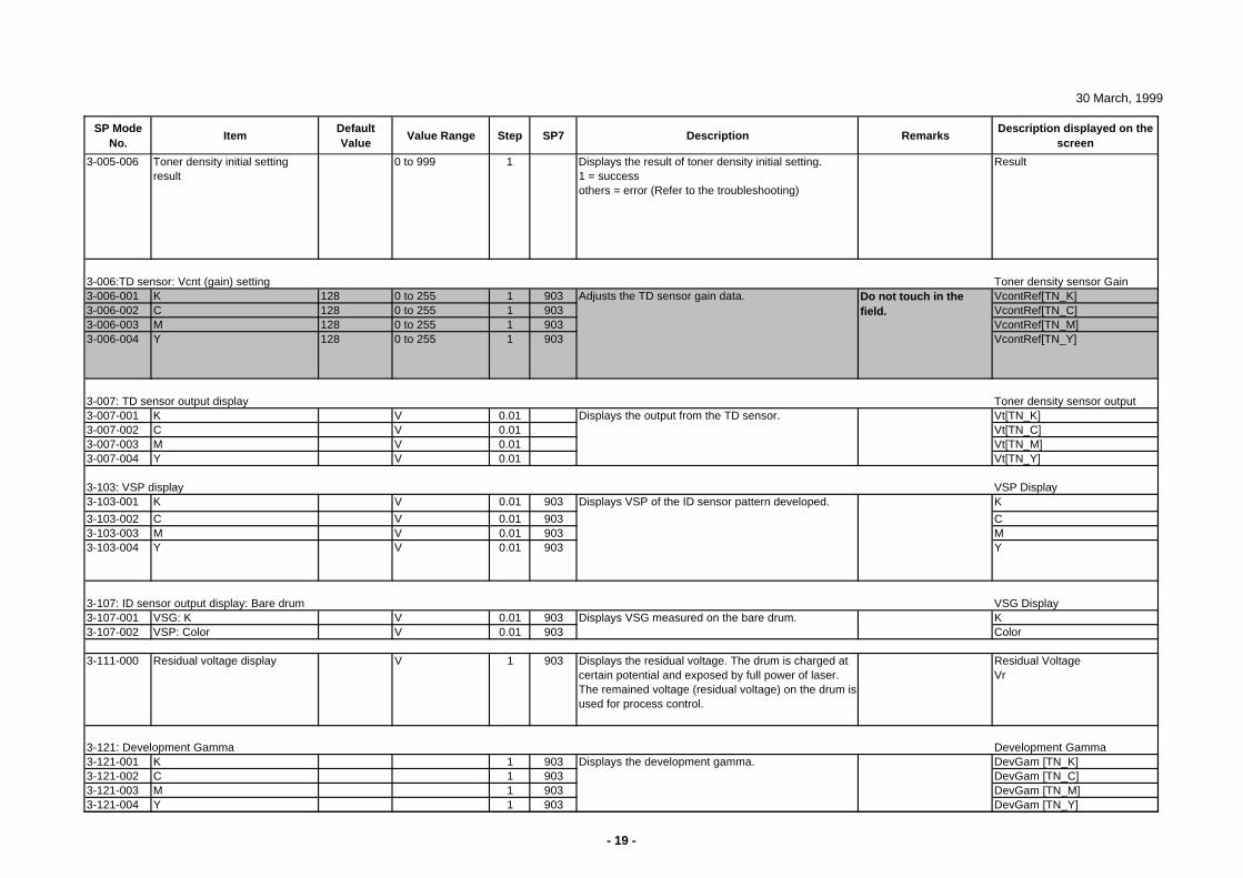
30 March, 1999
SP Mode No.
ItemDefault Value
Value Range Step SP7 Description RemarksDescription displayed on the
screen
3-005-006 Toner density initial setting result
0 to 999 1 Displays the result of toner density initial setting.1 = successothers = error (Refer to the troubleshooting)
Result
3-006:TD sensor: Vcnt (gain) setting Toner density sensor Gain3-006-001 K 128 0 to 255 1 903 VcontRef[TN_K]3-006-002 C 128 0 to 255 1 903 VcontRef[TN_C]3-006-003 M 128 0 to 255 1 903 VcontRef[TN_M]3-006-004 Y 128 0 to 255 1 903 VcontRef[TN_Y]
3-007: TD sensor output display Toner density sensor output3-007-001 K V 0.01 Vt[TN_K]3-007-002 C V 0.01 Vt[TN_C]3-007-003 M V 0.01 Vt[TN_M]3-007-004 Y V 0.01 Vt[TN_Y]
3-103: VSP display VSP Display3-103-001 K V 0.01 903 K
3-103-002 C V 0.01 903 C3-103-003 M V 0.01 903 M3-103-004 Y V 0.01 903 Y
3-107: ID sensor output display: Bare drum VSG Display3-107-001 VSG: K V 0.01 903 K3-107-002 VSP: Color V 0.01 903 Color
3-111-000 Residual voltage display V 1 903 Displays the residual voltage. The drum is charged at certain potential and exposed by full power of laser. The remained voltage (residual voltage) on the drum is used for process control.
Residual VoltageVr
3-121: Development Gamma Development Gamma3-121-001 K 1 903 DevGam [TN_K]3-121-002 C 1 903 DevGam [TN_C]3-121-003 M 1 903 DevGam [TN_M]3-121-004 Y 1 903 DevGam [TN_Y]
Do not touch in the field.
Displays the output from the TD sensor.
Adjusts the TD sensor gain data.
Displays VSP of the ID sensor pattern developed.
Displays the development gamma.
Displays VSG measured on the bare drum.
- 19 -
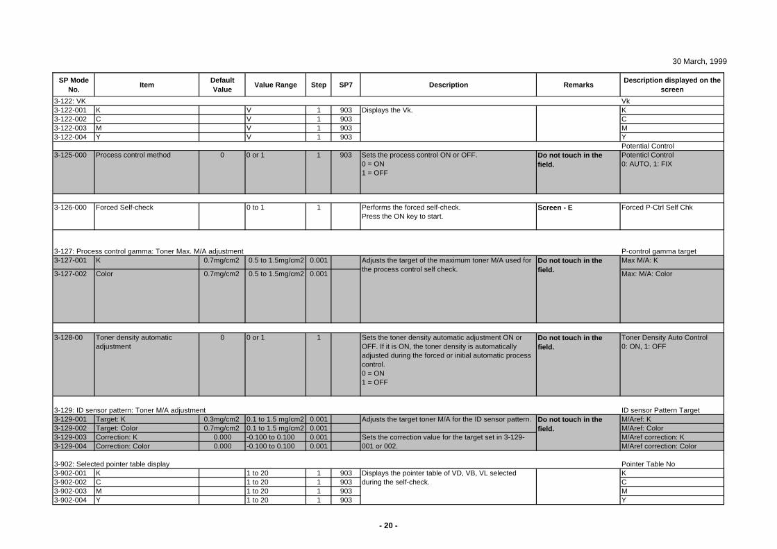
30 March, 1999
SP Mode No.
ItemDefault Value
Value Range Step SP7 Description RemarksDescription displayed on the
screen
Vk3-122-001 K V 1 903 K3-122-002 C V 1 903 C3-122-003 M V 1 903 M3-122-004 Y V 1 903 Y
Potential Control3-125-000 Process control method 0 0 or 1 1 903 Sets the process control ON or OFF.
0 = ON1 = OFF
Do not touch in the field.
Potenticl Control0: AUTO, 1: FIX
3-126-000 Forced Self-check 0 to 1 1 Performs the forced self-check.Press the ON key to start.
Screen - E Forced P-Ctrl Self Chk
3-127: Process control gamma: Toner Max. M/A adjustment P-control gamma target3-127-001 K 0.7mg/cm2 0.5 to 1.5mg/cm2 0.001 Max M/A: K
3-127-002 Color 0.7mg/cm2 0.5 to 1.5mg/cm2 0.001 Max: M/A: Color
3-128-00 Toner density automatic adjustment
0 0 or 1 1 Sets the toner density automatic adjustment ON or OFF. If it is ON, the toner density is automatically adjusted during the forced or initial automatic process control.0 = ON1 = OFF
Do not touch in the field.
Toner Density Auto Control0: ON, 1: OFF
3-129: ID sensor pattern: Toner M/A adjustment ID sensor Pattern Target3-129-001 Target: K 0.3mg/cm2 0.1 to 1.5 mg/cm2 0.001 M/Aref: K3-129-002 Target: Color 0.7mg/cm2 0.1 to 1.5 mg/cm2 0.001 M/Aref: Color3-129-003 Correction: K 0.000 -0.100 to 0.100 0.001 M/Aref correction: K3-129-004 Correction: Color 0.000 -0.100 to 0.100 0.001 M/Aref correction: Color
3-902: Selected pointer table display Pointer Table No3-902-001 K 1 to 20 1 903 K3-902-002 C 1 to 20 1 903 C3-902-003 M 1 to 20 1 903 M3-902-004 Y 1 to 20 1 903 Y
Do not touch in the field.
Do not touch in the field.
Sets the correction value for the target set in 3-129-001 or 002.
Adjusts the target of the maximum toner M/A used for the process control self check.
Adjusts the target toner M/A for the ID sensor pattern.
Displays the pointer table of VD, VB, VL selected during the self-check.
Displays the Vk.3-122: VK
- 20 -
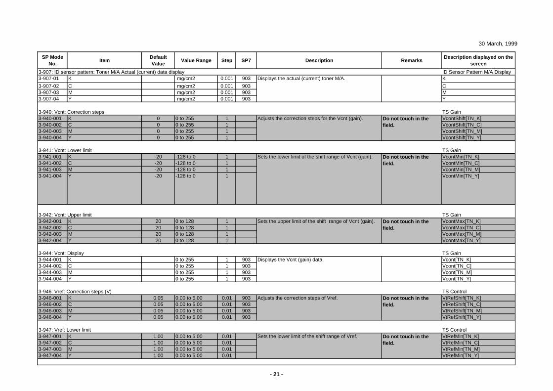
30 March, 1999
SP Mode No.
ItemDefault Value
Value Range Step SP7 Description RemarksDescription displayed on the
screen
3-907: ID sensor pattern: Toner M/A Actual (current) data display ID Sensor Pattern M/A Display3-907-01 K mg/cm2 0.001 903 K
3-907-02 C mg/cm2 0.001 903 C3-907-03 M mg/cm2 0.001 903 M3-907-04 Y mg/cm2 0.001 903 Y
3-940: Vcnt: Correction steps TS Gain3-940-001 K 0 0 to 255 1 VcontShift[TN_K]3-940-002 C 0 0 to 255 1 VcontShift[TN_C]3-940-003 M 0 0 to 255 1 VcontShift[TN_M]3-940-004 Y 0 0 to 255 1 VcontShift[TN_Y]
3-941: Vcnt: Lower limit TS Gain3-941-001 K -20 -128 to 0 1 VcontMin[TN_K]3-941-002 C -20 -128 to 0 1 VcontMin[TN_C]3-941-003 M -20 -128 to 0 1 VcontMin[TN_M]3-941-004 Y -20 -128 to 0 1 VcontMin[TN_Y]
3-942: Vcnt: Upper limit TS Gain3-942-001 K 20 0 to 128 1 VcontMax[TN_K]3-942-002 C 20 0 to 128 1 VcontMax[TN_C]3-942-003 M 20 0 to 128 1 VcontMax[TN_M]3-942-004 Y 20 0 to 128 1 VcontMax[TN_Y]
3-944: Vcnt: Display TS Gain3-944-001 K 0 to 255 1 903 Vcont[TN_K]3-944-002 C 0 to 255 1 903 Vcont[TN_C]3-944-003 M 0 to 255 1 903 Vcont[TN_M]3-944-004 Y 0 to 255 1 903 Vcont[TN_Y]
3-946: Vref: Correction steps (V) TS Control3-946-001 K 0.05 0.00 to 5.00 0.01 903 VtRefShift[TN_K]3-946-002 C 0.05 0.00 to 5.00 0.01 903 VtRefShift[TN_C]3-946-003 M 0.05 0.00 to 5.00 0.01 903 VtRefShift[TN_M]3-946-004 Y 0.05 0.00 to 5.00 0.01 903 VtRefShift[TN_Y]
3-947: Vref: Lower limit TS Control3-947-001 K 1.00 0.00 to 5.00 0.01 VtRefMin[TN_K]3-947-002 C 1.00 0.00 to 5.00 0.01 VtRefMin[TN_C]3-947-003 M 1.00 0.00 to 5.00 0.01 VtRefMin[TN_M]3-947-004 Y 1.00 0.00 to 5.00 0.01 VtRefMin[TN_Y]
Do not touch in the field.
Do not touch in the field.
Do not touch in the field.
Do not touch in the field.
Do not touch in the field.
Displays the actual (current) toner M/A.
Sets the lower limit of the shift range of Vcnt (gain).
Adjusts the correction steps of Vref.
Sets the lower limit of the shift range of Vref.
Displays the Vcnt (gain) data.
Adjusts the correction steps for the Vcnt (gain).
Sets the upper limit of the shift range of Vcnt (gain).
- 21 -
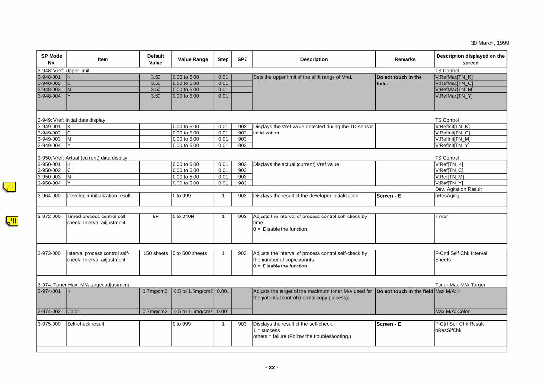
30 March, 1999
SP Mode No.
ItemDefault Value
Value Range Step SP7 Description RemarksDescription displayed on the
screen
3-948: Vref: Upper limit TS Control3-948-001 K 3.50 0.00 to 5.00 0.01 VtRefMax[TN_K]3-948-002 C 3.50 0.00 to 5.00 0.01 VtRefMax[TN_C]3-948-003 M 3.50 0.00 to 5.00 0.01 VtRefMax[TN_M]3-948-004 Y 3.50 0.00 to 5.00 0.01 VtRefMax[TN_Y]
3-949: Vref: Initial data display TS Control3-949-001 K 0.00 to 5.00 0.01 903 VtReflnit[TN_K]3-949-002 C 0.00 to 5.00 0.01 903 VtReflnit[TN_C]3-949-003 M 0.00 to 5.00 0.01 903 VtReflnit[TN_M]3-949-004 Y 0.00 to 5.00 0.01 903 VtReflnit[TN_Y]
3-950: Vref: Actual (current) data display TS Control3-950-001 K 0.00 to 5.00 0.01 903 VtRef[TN_K]3-950-002 C 0.00 to 5.00 0.01 903 VtRef[TN_C]3-950-003 M 0.00 to 5.00 0.01 903 VtRef[TN_M]3-950-004 Y 0.00 to 5.00 0.01 903 VtRef[TN_Y]
Dev. Agitation Result3-964-000 Developer initialization result 0 to 999 1 903 Displays the result of the developer initialization. Screen - E bResAging
3-972-000 Timed process control self-check: Interval adjustment
6H 0 to 240H 1 903 Adjusts the interval of process control self-check by time.0 = Disable the function
Timer
3-973-000 Interval process control self-check: Interval adjustment
150 sheets 0 to 500 sheets 1 903 Adjusts the interval of process control self-check by the number of copies/prints.0 = Disable the function
P-Cntl Self Chk IntervalSheets
3-974: Toner Max. M/A target adjustment Toner Max M/A Target3-974-001 K 0.7mg/cm2 0.5 to 1.5mg/cm2 0.001 Max M/A: K
3-974-002 Color 0.7mg/cm2 0.5 to 1.5mg/cm2 0.001 Max M/A: Color
3-975-000 Self-check result 0 to 999 1 903 Displays the result of the self-check.1 = successothers = failure (Follow the troubleshooting.)
Screen - E P-Ctrl Self Chk ResultbResSlfChk
Adjusts the target of the maximum toner M/A used for the potential control (normal copy process).
Displays the actual (current) Vref value.
Do not touch in the field
Displays the Vref value detected during the TD sensor initialization.
Do not touch in the field.
Sets the upper limit of the shift range of Vref.
- 22 -
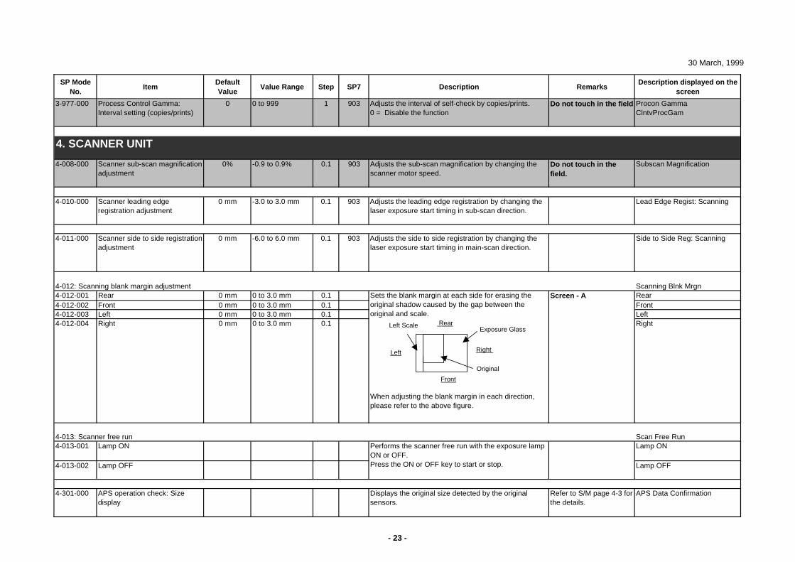
30 March, 1999
SP Mode No.
ItemDefault Value
Value Range Step SP7 Description RemarksDescription displayed on the
screen
3-977-000 Process Control Gamma: Interval setting (copies/prints)
0 0 to 999 1 903 Adjusts the interval of self-check by copies/prints. 0 = Disable the function
Do not touch in the field Procon GammaClntvProcGam
4-008-000 Scanner sub-scan magnification adjustment
0% -0.9 to 0.9% 0.1 903 Adjusts the sub-scan magnification by changing the scanner motor speed.
Do not touch in the field.
Subscan Magnification
4-010-000 Scanner leading edge registration adjustment
0 mm -3.0 to 3.0 mm 0.1 903 Adjusts the leading edge registration by changing the laser exposure start timing in sub-scan direction.
Lead Edge Regist: Scanning
4-011-000 Scanner side to side registration adjustment
0 mm -6.0 to 6.0 mm 0.1 903 Adjusts the side to side registration by changing the laser exposure start timing in main-scan direction.
Side to Side Reg: Scanning
4-012: Scanning blank margin adjustment Scanning Blnk Mrgn4-012-001 Rear 0 mm 0 to 3.0 mm 0.1 Rear4-012-002 Front 0 mm 0 to 3.0 mm 0.1 Front4-012-003 Left 0 mm 0 to 3.0 mm 0.1 Left4-012-004 Right 0 mm 0 to 3.0 mm 0.1 Right
4-013: Scanner free run Scan Free Run4-013-001 Lamp ON Lamp ON
4-013-002 Lamp OFF Lamp OFF
4-301-000 APS operation check: Size display
Displays the original size detected by the original sensors.
Refer to S/M page 4-3 for the details.
APS Data Confirmation
4. SCANNER UNIT
Sets the blank margin at each side for erasing the original shadow caused by the gap between the original and scale.
When adjusting the blank margin in each direction, please refer to the above figure.
Performs the scanner free run with the exposure lamp ON or OFF.Press the ON or OFF key to start or stop.
Screen - A
Left
Left ScaleExposure Glass
Original
Front
Right
Rear
- 23 -
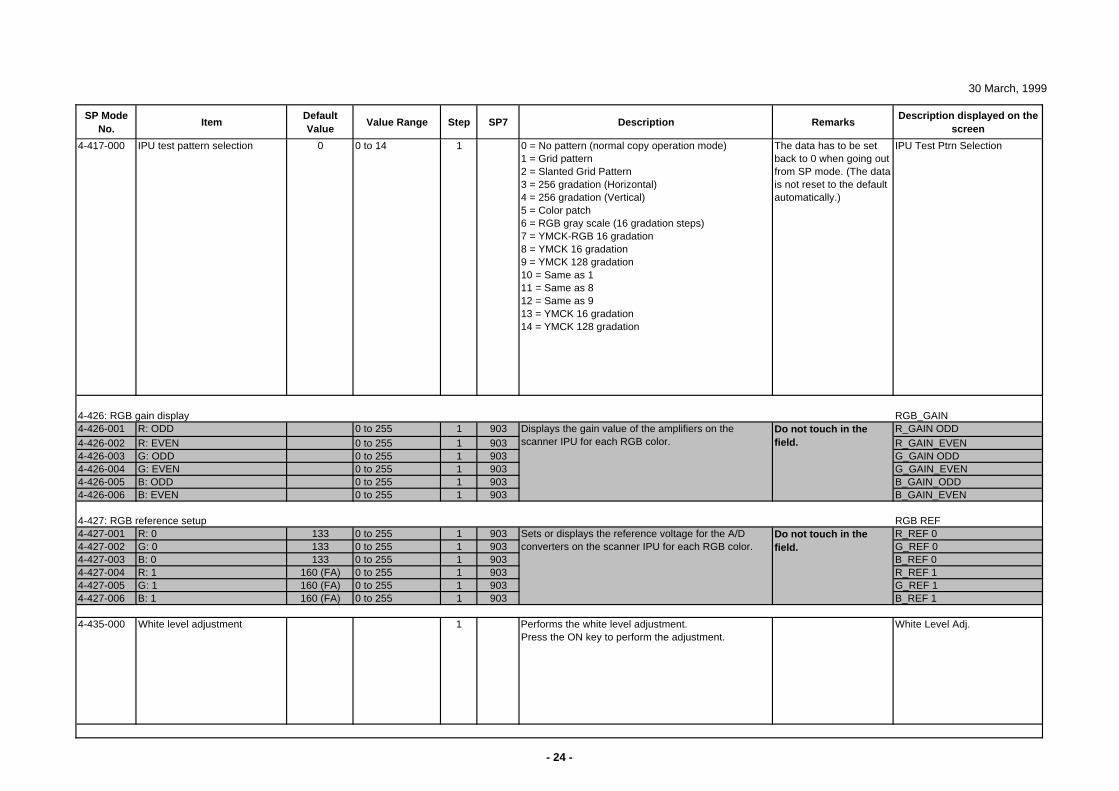
30 March, 1999
SP Mode No.
ItemDefault Value
Value Range Step SP7 Description RemarksDescription displayed on the
screen
4-417-000 IPU test pattern selection 0 0 to 14 1 0 = No pattern (normal copy operation mode)1 = Grid pattern2 = Slanted Grid Pattern3 = 256 gradation (Horizontal)4 = 256 gradation (Vertical)5 = Color patch6 = RGB gray scale (16 gradation steps)7 = YMCK-RGB 16 gradation8 = YMCK 16 gradation9 = YMCK 128 gradation10 = Same as 111 = Same as 812 = Same as 913 = YMCK 16 gradation14 = YMCK 128 gradation
The data has to be set back to 0 when going out from SP mode. (The data is not reset to the default automatically.)
IPU Test Ptrn Selection
4-426: RGB gain display RGB_GAIN4-426-001 R: ODD 0 to 255 1 903 R_GAIN ODD4-426-002 R: EVEN 0 to 255 1 903 R_GAIN_EVEN4-426-003 G: ODD 0 to 255 1 903 G_GAIN ODD4-426-004 G: EVEN 0 to 255 1 903 G_GAIN_EVEN4-426-005 B: ODD 0 to 255 1 903 B_GAIN_ODD4-426-006 B: EVEN 0 to 255 1 903 B_GAIN_EVEN
4-427: RGB reference setup RGB REF4-427-001 R: 0 133 0 to 255 1 903 R_REF 04-427-002 G: 0 133 0 to 255 1 903 G_REF 04-427-003 B: 0 133 0 to 255 1 903 B_REF 04-427-004 R: 1 160 (FA) 0 to 255 1 903 R_REF 14-427-005 G: 1 160 (FA) 0 to 255 1 903 G_REF 14-427-006 B: 1 160 (FA) 0 to 255 1 903 B_REF 1
4-435-000 White level adjustment 1 Performs the white level adjustment.Press the ON key to perform the adjustment.
White Level Adj.
Displays the gain value of the amplifiers on the scanner IPU for each RGB color.
Do not touch in the field.
Do not touch in the field.
Sets or displays the reference voltage for the A/D converters on the scanner IPU for each RGB color.
- 24 -
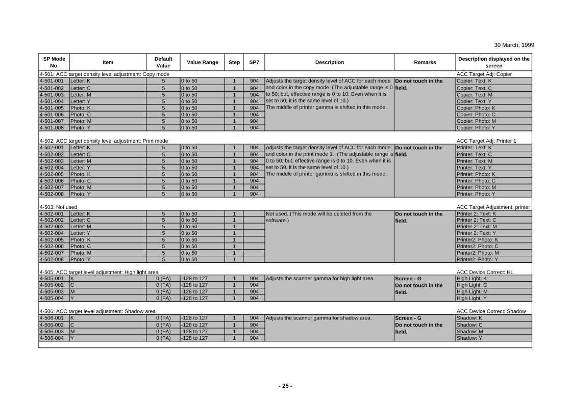
30 March, 1999
SP Mode No.
ItemDefault Value
Value Range Step SP7 Description RemarksDescription displayed on the
screen
4-501: ACC target density level adjustment: Copy mode ACC Target Adj: Copier4-501-001 Letter: K 5 0 to 50 1 904 Copier: Text: K4-501-002 Letter: C 5 0 to 50 1 904 Copier: Text: C4-501-003 Letter: M 5 0 to 50 1 904 Copier: Text: M4-501-004 Letter: Y 5 0 to 50 1 904 Copier: Text: Y4-501-005 Photo: K 5 0 to 50 1 904 Copier: Photo: K4-501-006 Photo: C 5 0 to 50 1 904 Copier: Photo: C4-501-007 Photo: M 5 0 to 50 1 904 Copier: Photo: M4-501-008 Photo: Y 5 0 to 50 1 904 Copier: Photo: Y
4-502: ACC target density level adjustment: Print mode ACC Target Adj: Printer 14-502-001 Letter: K 5 0 to 50 1 904 Printer: Text: K4-502-002 Letter: C 5 0 to 50 1 904 Printer: Text: C4-502-003 Letter: M 5 0 to 50 1 904 Printer: Text: M4-502-004 Letter: Y 5 0 to 50 1 904 Printer: Text: Y4-502-005 Photo: K 5 0 to 50 1 904 Printer: Photo: K4-502-006 Photo: C 5 0 to 50 1 904 Printer: Photo: C4-502-007 Photo: M 5 0 to 50 1 904 Printer: Photo: M4-502-008 Photo: Y 5 0 to 50 1 904 Printer: Photo: Y
4-503: Not used ACC Target Adjustment: printer 4-502-001 Letter: K 5 0 to 50 1 Printer 2: Text: K4-502-002 Letter: C 5 0 to 50 1 Printer 2: Text: C4-502-003 Letter: M 5 0 to 50 1 Printer 2: Text: M4-502-004 Letter: Y 5 0 to 50 1 Printer 2: Text: Y4-502-005 Photo: K 5 0 to 50 1 Printer2: Photo: K4-502-006 Photo: C 5 0 to 50 1 Printer2: Photo: C4-502-007 Photo: M 5 0 to 50 1 Printer2: Photo: M4-502-008 Photo: Y 5 0 to 50 1 Printer2: Photo: Y
4-505: ACC target level adjustment: High light area ACC Device Correct: HL4-505-001 K 0 (FA) -128 to 127 1 904 High Light: K4-505-002 C 0 (FA) -128 to 127 1 904 High Light: C4-505-003 M 0 (FA) -128 to 127 1 904 High Light: M4-505-004 Y 0 (FA) -128 to 127 1 904 High Light: Y
4-506: ACC target level adjustment: Shadow area ACC Device Correct: Shadow4-506-001 K 0 (FA) -128 to 127 1 904 Shadow: K4-506-002 C 0 (FA) -128 to 127 1 904 Shadow: C4-506-003 M 0 (FA) -128 to 127 1 904 Shadow: M4-506-004 Y 0 (FA) -128 to 127 1 904 Shadow: Y
Screen - GDo not touch in the field.
Do not touch in the field.
Do not touch in the field.
Do not touch in the field.
Adjusts the scanner gamma for high light area.
Adjusts the scanner gamma for shadow area.
Not used. (This mode will be deleted from the software.)
Screen - GDo not touch in the field.
Adjusts the target density level of ACC for each mode and color in the copy mode. (The adjustable range is 0 to 50; but, effective range is 0 to 10. Even when it is set to 50, it is the same level of 10.)The middle of printer gamma is shifted in this mode.
Adjusts the target density level of ACC for each mode and color in the print mode 1. (The adjustable range is 0 to 50; but, effective range is 0 to 10. Even when it is set to 50, it is the same level of 10.)The middle of printer gamma is shifted in this mode.
- 25 -
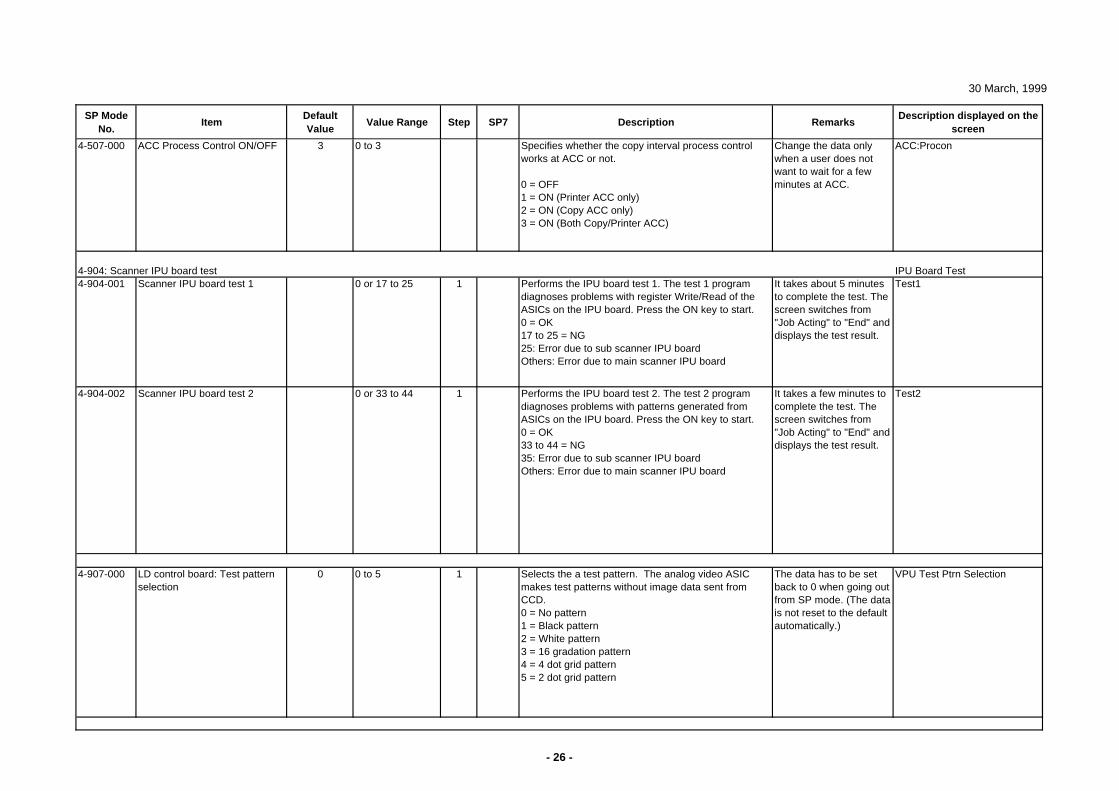
30 March, 1999
SP Mode No.
ItemDefault Value
Value Range Step SP7 Description RemarksDescription displayed on the
screen
4-507-000 ACC Process Control ON/OFF 3 0 to 3 Specifies whether the copy interval process control works at ACC or not.
0 = OFF1 = ON (Printer ACC only)2 = ON (Copy ACC only)3 = ON (Both Copy/Printer ACC)
Change the data only when a user does not want to wait for a few minutes at ACC.
ACC:Procon
4-904: Scanner IPU board test IPU Board Test4-904-001 Scanner IPU board test 1 0 or 17 to 25 1 Performs the IPU board test 1. The test 1 program
diagnoses problems with register Write/Read of the ASICs on the IPU board. Press the ON key to start.0 = OK17 to 25 = NG25: Error due to sub scanner IPU boardOthers: Error due to main scanner IPU board
It takes about 5 minutes to complete the test. The screen switches from "Job Acting" to "End" and displays the test result.
Test1
4-904-002 Scanner IPU board test 2 0 or 33 to 44 1 Performs the IPU board test 2. The test 2 program diagnoses problems with patterns generated from ASICs on the IPU board. Press the ON key to start.0 = OK33 to 44 = NG35: Error due to sub scanner IPU boardOthers: Error due to main scanner IPU board
It takes a few minutes to complete the test. The screen switches from "Job Acting" to "End" and displays the test result.
Test2
4-907-000 LD control board: Test pattern selection
0 0 to 5 1 Selects the a test pattern. The analog video ASIC makes test patterns without image data sent from CCD.0 = No pattern1 = Black pattern2 = White pattern3 = 16 gradation pattern4 = 4 dot grid pattern5 = 2 dot grid pattern
The data has to be set back to 0 when going out from SP mode. (The data is not reset to the default automatically.)
VPU Test Ptrn Selection
- 26 -
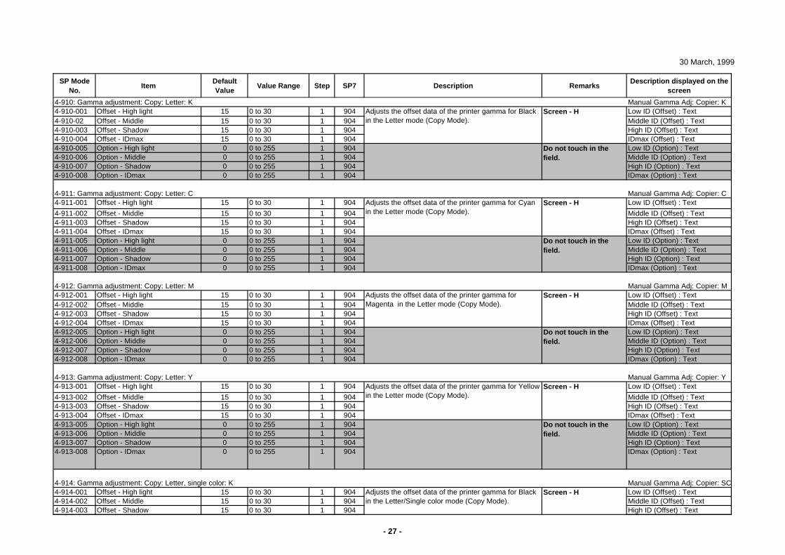
30 March, 1999
SP Mode No.
ItemDefault Value
Value Range Step SP7 Description RemarksDescription displayed on the
screen
4-910: Gamma adjustment: Copy: Letter: K Manual Gamma Adj: Copier: K4-910-001 Offset - High light 15 0 to 30 1 904 Low ID (Offset) : Text4-910-02 Offset - Middle 15 0 to 30 1 904 Middle ID (Offset) : Text4-910-003 Offset - Shadow 15 0 to 30 1 904 High ID (Offset) : Text4-910-004 Offset - IDmax 15 0 to 30 1 904 IDmax (Offset) : Text4-910-005 Option - High light 0 0 to 255 1 904 Low ID (Option) : Text4-910-006 Option - Middle 0 0 to 255 1 904 Middle ID (Option) : Text4-910-007 Option - Shadow 0 0 to 255 1 904 High ID (Option) : Text4-910-008 Option - IDmax 0 0 to 255 1 904 IDmax (Option) : Text
4-911: Gamma adjustment: Copy: Letter: C Manual Gamma Adj: Copier: C4-911-001 Offset - High light 15 0 to 30 1 904 Low ID (Offset) : Text
4-911-002 Offset - Middle 15 0 to 30 1 904 Middle ID (Offset) : Text4-911-003 Offset - Shadow 15 0 to 30 1 904 High ID (Offset) : Text4-911-004 Offset - IDmax 15 0 to 30 1 904 IDmax (Offset) : Text4-911-005 Option - High light 0 0 to 255 1 904 Low ID (Option) : Text4-911-006 Option - Middle 0 0 to 255 1 904 Middle ID (Option) : Text4-911-007 Option - Shadow 0 0 to 255 1 904 High ID (Option) : Text4-911-008 Option - IDmax 0 0 to 255 1 904 IDmax (Option) : Text
4-912: Gamma adjustment: Copy: Letter: M Manual Gamma Adj: Copier: M4-912-001 Offset - High light 15 0 to 30 1 904 Low ID (Offset) : Text4-912-002 Offset - Middle 15 0 to 30 1 904 Middle ID (Offset) : Text4-912-003 Offset - Shadow 15 0 to 30 1 904 High ID (Offset) : Text4-912-004 Offset - IDmax 15 0 to 30 1 904 IDmax (Offset) : Text4-912-005 Option - High light 0 0 to 255 1 904 Low ID (Option) : Text4-912-006 Option - Middle 0 0 to 255 1 904 Middle ID (Option) : Text4-912-007 Option - Shadow 0 0 to 255 1 904 High ID (Option) : Text4-912-008 Option - IDmax 0 0 to 255 1 904 IDmax (Option) : Text
4-913: Gamma adjustment: Copy: Letter: Y Manual Gamma Adj: Copier: Y4-913-001 Offset - High light 15 0 to 30 1 904 Low ID (Offset) : Text
4-913-002 Offset - Middle 15 0 to 30 1 904 Middle ID (Offset) : Text4-913-003 Offset - Shadow 15 0 to 30 1 904 High ID (Offset) : Text4-913-004 Offset - IDmax 15 0 to 30 1 904 IDmax (Offset) : Text4-913-005 Option - High light 0 0 to 255 1 904 Low ID (Option) : Text4-913-006 Option - Middle 0 0 to 255 1 904 Middle ID (Option) : Text4-913-007 Option - Shadow 0 0 to 255 1 904 High ID (Option) : Text4-913-008 Option - IDmax 0 0 to 255 1 904 IDmax (Option) : Text
4-914: Gamma adjustment: Copy: Letter, single color: K Manual Gamma Adj: Copier: SC4-914-001 Offset - High light 15 0 to 30 1 904 Low ID (Offset) : Text4-914-002 Offset - Middle 15 0 to 30 1 904 Middle ID (Offset) : Text4-914-003 Offset - Shadow 15 0 to 30 1 904 High ID (Offset) : Text
Adjusts the offset data of the printer gamma for Yellow in the Letter mode (Copy Mode).
Screen - H
Do not touch in the field.
Screen - H
Do not touch in the field.
Adjusts the offset data of the printer gamma for Magenta in the Letter mode (Copy Mode).
Screen - H
Do not touch in the field.
Do not touch in the field.
Screen - H
Adjusts the offset data of the printer gamma for Black in the Letter/Single color mode (Copy Mode).
Adjusts the offset data of the printer gamma for Cyan in the Letter mode (Copy Mode).
Adjusts the offset data of the printer gamma for Black in the Letter mode (Copy Mode).
Screen - H
- 27 -
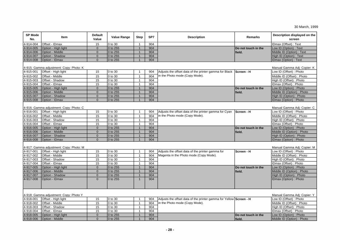
30 March, 1999
SP Mode No.
ItemDefault Value
Value Range Step SP7 Description RemarksDescription displayed on the
screen
4-914-004 Offset - IDmax 15 0 to 30 1 904 IDmax (Offset) : Text4-914-005 Option - High light 0 0 to 255 1 904 Low ID (Option) : Text4-914-006 Option - Middle 0 0 to 255 1 904 Middle ID (Option) : Text4-914-007 Option - Shadow 0 0 to 255 1 904 High ID (Option) : Text4-914-008 Option - IDmax 0 0 to 255 1 904 IDmax (Option) : Text
4-915: Gamma adjustment: Copy: Photo: K Manual Gamma Adj: Copier: K4-915-001 Offset - High light 15 0 to 30 1 904 Low ID (Offset) : Photo
4-915-002 Offset - Middle 15 0 to 30 1 904 Middle ID (Offset) : Photo4-915-003 Offset - Shadow 15 0 to 30 1 904 High ID (Offset) : Photo4-915-004 Offset - IDmax 15 0 to 30 1 904 IDmax (Offset) : Photo4-915-005 Option - High light 0 0 to 255 1 904 Low ID (Option) : Photo4-915-006 Option - Middle 0 0 to 255 1 904 Middle ID (Option) : Photo4-915-007 Option - Shadow 0 0 to 255 1 904 High ID (Option) : Photo4-915-008 Option - IDmax 0 0 to 255 1 904 IDmax (Option) : Photo
4-916: Gamma adjustment: Copy: Photo: C Manual Gamma Adj: Copier: C4-916-001 Offset - High light 15 0 to 30 1 904 Low ID (Offset) : Photo4-916-002 Offset - Middle 15 0 to 30 1 904 Middle ID (Offset) : Photo4-916-003 Offset - Shadow 15 0 to 30 1 904 High ID (Offset) : Photo4-916-004 Offset - IDmax 15 0 to 30 1 904 IDmax (Offset) : Photo4-916-005 Option - High light 0 0 to 255 1 904 Low ID (Option) : Photo4-916-006 Option - Middle 0 0 to 255 1 904 Middle ID (Option) : Photo4-916-007 Option - Shadow 0 0 to 255 1 904 High ID (Option) : Photo4-916-008 Option - IDmax 0 0 to 255 1 904 IDmax (Option) : Photo
4-917: Gamma adjustment: Copy: Photo: M Manual Gamma Adj: Copier: M4-917-001 Offset - High light 15 0 to 30 1 904 Low ID (Offset) : Photo4-917-002 Offset - Middle 15 0 to 30 1 904 Middle ID (Offset) : Photo4-917-003 Offset - Shadow 15 0 to 30 1 904 High ID (Offset) : Photo4-917-004 Offset - IDmax 15 0 to 30 1 904 IDmax (Offset) : Photo4-917-005 Option - High light 0 0 to 255 1 904 Low ID (Option) : Photo4-917-006 Option - Middle 0 0 to 255 1 904 Middle ID (Option) : Photo4-917-007 Option - Shadow 0 0 to 255 1 904 High ID (Option) : Photo4-917-008 Option - IDmax 0 0 to 255 1 904 IDmax (Option) : Photo
4-918: Gamma adjustment: Copy: Photo Y Manual Gamma Adj: Copier: Y4-918-001 Offset - High light 15 0 to 30 1 904 Low ID (Offset) : Photo4-918-002 Offset - Middle 15 0 to 30 1 904 Middle ID (Offset) : Photo4-918-003 Offset - Shadow 15 0 to 30 1 904 High ID (Offset) : Photo4-918-004 Offset - IDmax 15 0 to 30 1 904 IDmax (Offset) : Photo4-918-005 Option - High light 0 0 to 255 1 904 Low ID (Option) : Photo4-918-006 Option - Middle 0 0 to 255 1 904 Middle ID (Option) : Photo
Adjusts the offset data of the printer gamma for Yellow in the Photo mode (Copy Mode).
Screen - H
Do not touch in the field.
Do not touch in the field.
Do not touch in the field.
Screen - H
Screen - H
Adjusts the offset data of the printer gamma for Magenta in the Photo mode (Copy Mode).
Adjusts the offset data of the printer gamma for Black in the Photo mode (Copy Mode).
Do not touch in the field.
Screen - H
Adjusts the offset data of the printer gamma for Cyan in the Photo mode (Copy Mode).
Do not touch in the field.
- 28 -
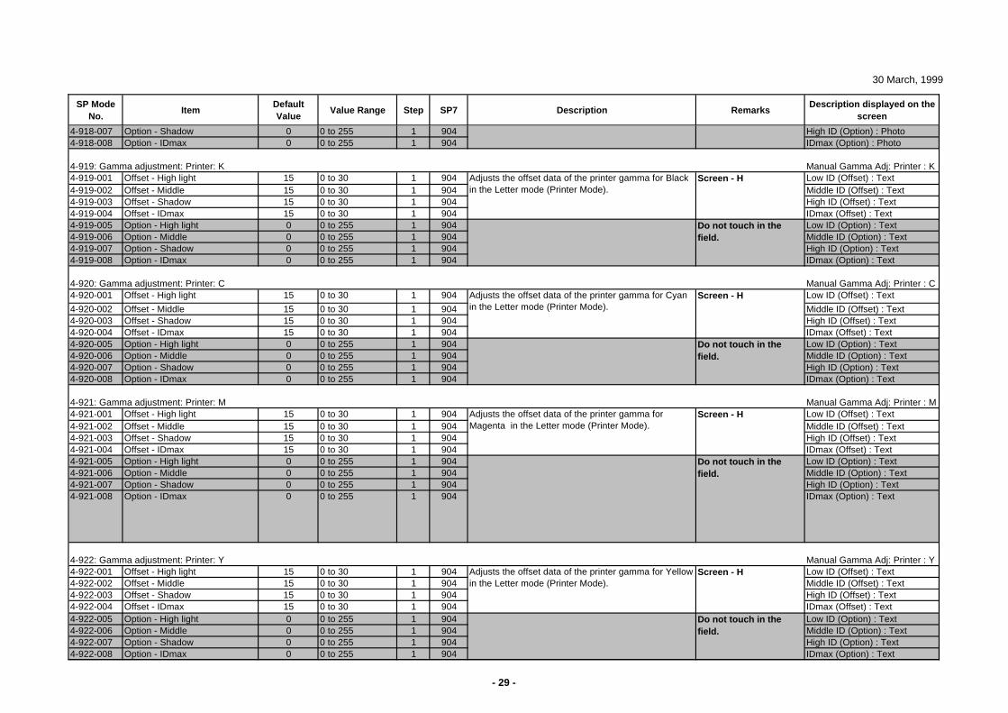
30 March, 1999
SP Mode No.
ItemDefault Value
Value Range Step SP7 Description RemarksDescription displayed on the
screen
4-918-007 Option - Shadow 0 0 to 255 1 904 High ID (Option) : Photo4-918-008 Option - IDmax 0 0 to 255 1 904 IDmax (Option) : Photo
4-919: Gamma adjustment: Printer: K Manual Gamma Adj: Printer : K4-919-001 Offset - High light 15 0 to 30 1 904 Low ID (Offset) : Text4-919-002 Offset - Middle 15 0 to 30 1 904 Middle ID (Offset) : Text4-919-003 Offset - Shadow 15 0 to 30 1 904 High ID (Offset) : Text4-919-004 Offset - IDmax 15 0 to 30 1 904 IDmax (Offset) : Text4-919-005 Option - High light 0 0 to 255 1 904 Low ID (Option) : Text4-919-006 Option - Middle 0 0 to 255 1 904 Middle ID (Option) : Text4-919-007 Option - Shadow 0 0 to 255 1 904 High ID (Option) : Text4-919-008 Option - IDmax 0 0 to 255 1 904 IDmax (Option) : Text
4-920: Gamma adjustment: Printer: C Manual Gamma Adj: Printer : C4-920-001 Offset - High light 15 0 to 30 1 904 Low ID (Offset) : Text
4-920-002 Offset - Middle 15 0 to 30 1 904 Middle ID (Offset) : Text4-920-003 Offset - Shadow 15 0 to 30 1 904 High ID (Offset) : Text4-920-004 Offset - IDmax 15 0 to 30 1 904 IDmax (Offset) : Text4-920-005 Option - High light 0 0 to 255 1 904 Low ID (Option) : Text4-920-006 Option - Middle 0 0 to 255 1 904 Middle ID (Option) : Text4-920-007 Option - Shadow 0 0 to 255 1 904 High ID (Option) : Text4-920-008 Option - IDmax 0 0 to 255 1 904 IDmax (Option) : Text
4-921: Gamma adjustment: Printer: M Manual Gamma Adj: Printer : M4-921-001 Offset - High light 15 0 to 30 1 904 Low ID (Offset) : Text4-921-002 Offset - Middle 15 0 to 30 1 904 Middle ID (Offset) : Text4-921-003 Offset - Shadow 15 0 to 30 1 904 High ID (Offset) : Text4-921-004 Offset - IDmax 15 0 to 30 1 904 IDmax (Offset) : Text4-921-005 Option - High light 0 0 to 255 1 904 Low ID (Option) : Text4-921-006 Option - Middle 0 0 to 255 1 904 Middle ID (Option) : Text4-921-007 Option - Shadow 0 0 to 255 1 904 High ID (Option) : Text4-921-008 Option - IDmax 0 0 to 255 1 904 IDmax (Option) : Text
4-922: Gamma adjustment: Printer: Y Manual Gamma Adj: Printer : Y4-922-001 Offset - High light 15 0 to 30 1 904 Low ID (Offset) : Text4-922-002 Offset - Middle 15 0 to 30 1 904 Middle ID (Offset) : Text4-922-003 Offset - Shadow 15 0 to 30 1 904 High ID (Offset) : Text4-922-004 Offset - IDmax 15 0 to 30 1 904 IDmax (Offset) : Text4-922-005 Option - High light 0 0 to 255 1 904 Low ID (Option) : Text4-922-006 Option - Middle 0 0 to 255 1 904 Middle ID (Option) : Text4-922-007 Option - Shadow 0 0 to 255 1 904 High ID (Option) : Text4-922-008 Option - IDmax 0 0 to 255 1 904 IDmax (Option) : Text
Screen - H
Do not touch in the field.
Adjusts the offset data of the printer gamma for Magenta in the Letter mode (Printer Mode).
Adjusts the offset data of the printer gamma for Yellow in the Letter mode (Printer Mode).
Do not touch in the field.
Do not touch in the field.
Screen - H
Adjusts the offset data of the printer gamma for Cyan in the Letter mode (Printer Mode).
Do not touch in the field.
Screen - H
Screen - H
Adjusts the offset data of the printer gamma for Black in the Letter mode (Printer Mode).
- 29 -
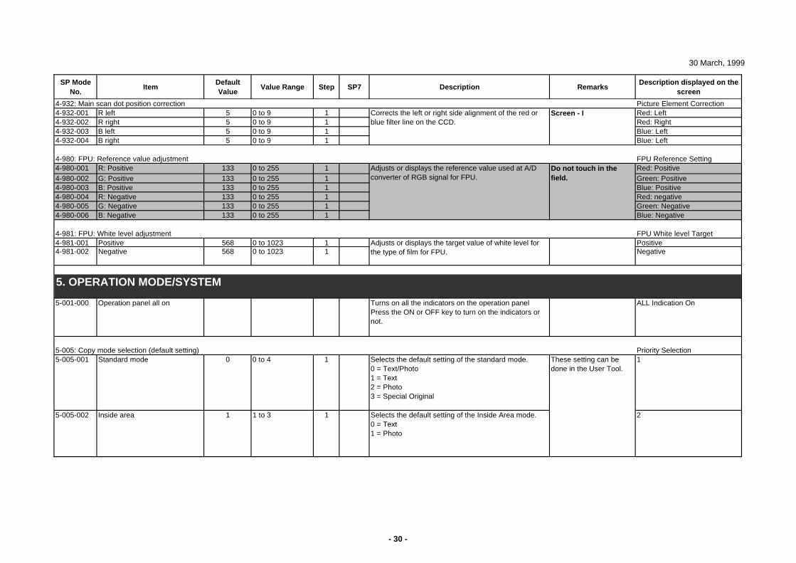
30 March, 1999
SP Mode No.
ItemDefault Value
Value Range Step SP7 Description RemarksDescription displayed on the
screen
4-932: Main scan dot position correction Picture Element Correction4-932-001 R left 5 0 to 9 1 Red: Left4-932-002 R right 5 0 to 9 1 Red: Right4-932-003 B left 5 0 to 9 1 Blue: Left4-932-004 B right 5 0 to 9 1 Blue: Left
4-980: FPU: Reference value adjustment FPU Reference Setting4-980-001 R: Positive 133 0 to 255 1 Red: Positive4-980-002 G: Positive 133 0 to 255 1 Green: Positive4-980-003 B: Positive 133 0 to 255 1 Blue: Positive4-980-004 R: Negative 133 0 to 255 1 Red: negative4-980-005 G: Negative 133 0 to 255 1 Green: Negative4-980-006 B: Negative 133 0 to 255 1 Blue: Negative
4-981: FPU: White level adjustment FPU White level Target4-981-001 Positive 568 0 to 1023 1 Positive4-981-002 Negative 568 0 to 1023 1 Negative
5-001-000 Operation panel all on Turns on all the indicators on the operation panel Press the ON or OFF key to turn on the indicators or not.
ALL Indication On
5-005: Copy mode selection (default setting) Priority Selection5-005-001 Standard mode 0 0 to 4 1 Selects the default setting of the standard mode.
0 = Text/Photo1 = Text2 = Photo3 = Special Original
1
5-005-002 Inside area 1 1 to 3 1 Selects the default setting of the Inside Area mode.0 = Text1 = Photo
2
Corrects the left or right side alignment of the red or blue filter line on the CCD.
Screen - I
These setting can be done in the User Tool.
5. OPERATION MODE/SYSTEM
Do not touch in the field.
Adjusts or displays the reference value used at A/D converter of RGB signal for FPU.
Adjusts or displays the target value of white level for the type of film for FPU.
- 30 -
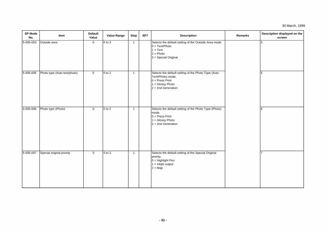
30 March, 1999
SP Mode No.
ItemDefault Value
Value Range Step SP7 Description RemarksDescription displayed on the
screen
5-005-003 Outside area 0 0 to 3 1 Selects the default setting of the Outside Area mode.0 = Text/Photo1 = Text2 = Photo3 = Special Original
3
5-005-005 Photo type (Auto text/photo) 0 0 to 2 1 Selects the default setting of the Photo Type (Auto Text/Photo) mode.0 = Press Print1 = Glossy Photo2 = 2nd Generation
5
5-005-006 Photo type (Photo) 0 0 to 2 1 Selects the default setting of the Photo Type (Photo) mode.0 = Press Print1 = Glossy Photo2 = 2nd Generation
6
5-005-007 Special original priority 0 0 to 2 1 Selects the default setting of the Special Original priority.0 = Highlight Pen1 = Inkjet output2 = Map
7
- 31 -
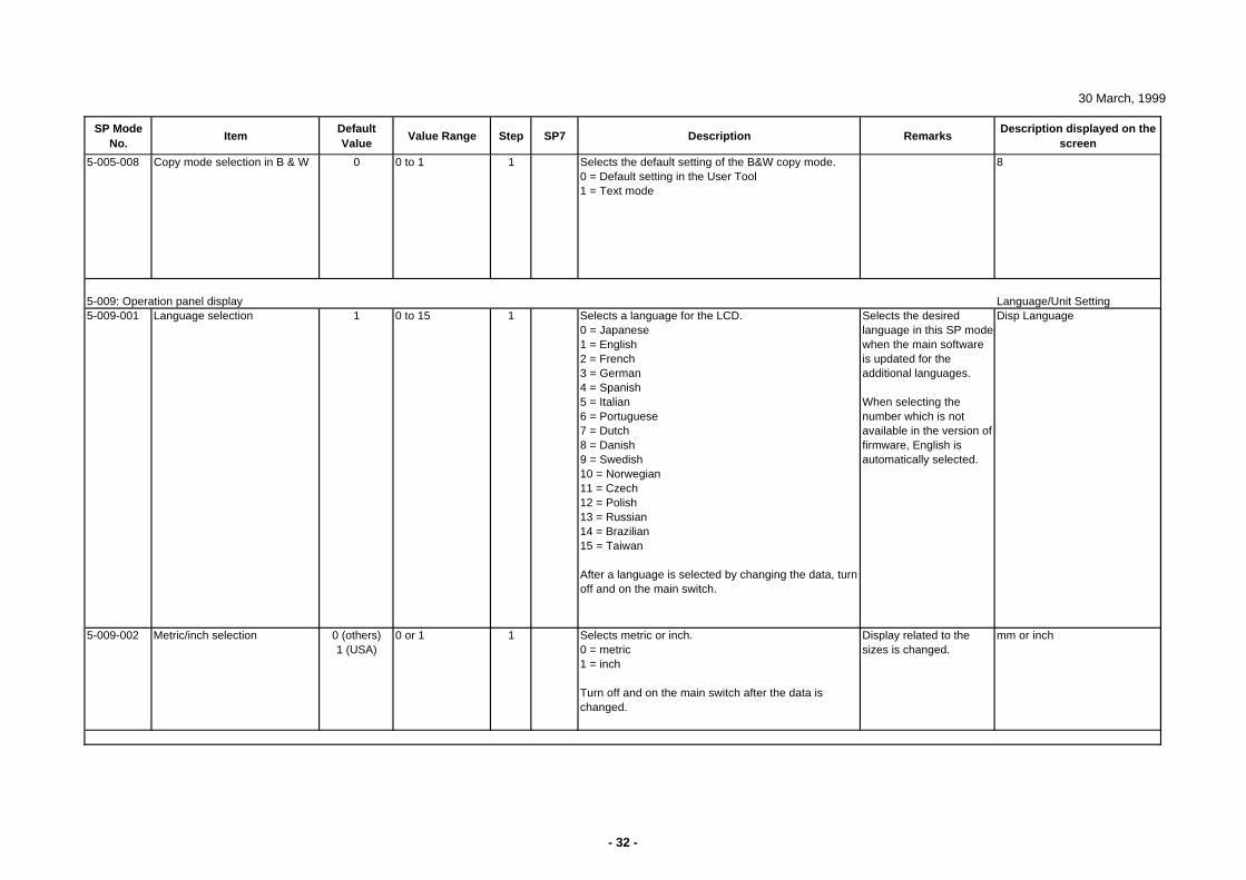
30 March, 1999
SP Mode No.
ItemDefault Value
Value Range Step SP7 Description RemarksDescription displayed on the
screen
5-005-008 Copy mode selection in B & W 0 0 to 1 1 Selects the default setting of the B&W copy mode.0 = Default setting in the User Tool1 = Text mode
8
5-009: Operation panel display Language/Unit Setting5-009-001 Language selection 1 0 to 15 1 Selects a language for the LCD.
0 = Japanese1 = English2 = French3 = German4 = Spanish5 = Italian6 = Portuguese7 = Dutch8 = Danish9 = Swedish10 = Norwegian11 = Czech12 = Polish13 = Russian14 = Brazilian15 = Taiwan
After a language is selected by changing the data, turn off and on the main switch.
Selects the desired language in this SP mode when the main software is updated for the additional languages.
When selecting the number which is not available in the version of firmware, English is automatically selected.
Disp Language
5-009-002 Metric/inch selection 0 (others)1 (USA)
0 or 1 1 Selects metric or inch.0 = metric1 = inch
Turn off and on the main switch after the data is changed.
Display related to the sizes is changed.
mm or inch
- 32 -
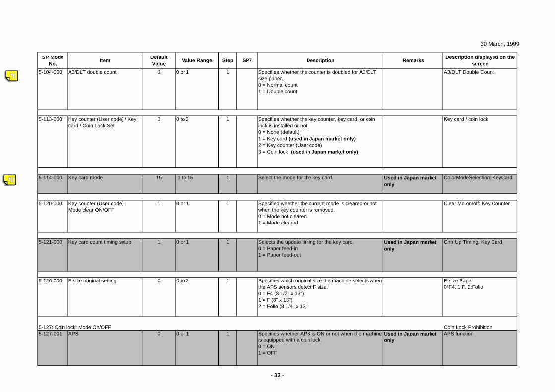
30 March, 1999
SP Mode No.
ItemDefault Value
Value Range Step SP7 Description RemarksDescription displayed on the
screen
5-104-000 A3/DLT double count 0 0 or 1 1 Specifies whether the counter is doubled for A3/DLT size paper.0 = Normal count1 = Double count
A3/DLT Double Count
5-113-000 Key counter (User code) / Key card / Coin Lock Set
0 0 to 3 1 Specifies whether the key counter, key card, or coin lock is installed or not.0 = None (default)1 = Key card (used in Japan market only)2 = Key counter (User code)3 = Coin lock (used in Japan market only)
Key card / coin lock
5-114-000 Key card mode 15 1 to 15 1 Select the mode for the key card. Used in Japan market only
ColorModeSelection: KeyCard
5-120-000 Key counter (User code):Mode clear ON/OFF
1 0 or 1 1 Specified whether the current mode is cleared or not when the key counter is removed.0 = Mode not cleared1 = Mode cleared
Clear Md on/off: Key Counter
5-121-000 Key card count timing setup 1 0 or 1 1 Selects the update timing for the key card.0 = Paper feed-in1 = Paper feed-out
Used in Japan market only
Cntr Up Timing: Key Card
5-126-000 F size original setting 0 0 to 2 1 Specifies which original size the machine selects when the APS sensors detect F size.0 = F4 (8 1/2" x 13")1 = F (8" x 13")2 = Folio (8 1/4" x 13")
F*size Paper0*F4, 1:F, 2:Folio
5-127: Coin lock: Mode On/OFF Coin Lock Prohibition5-127-001 APS 0 0 or 1 1 Specifies whether APS is ON or not when the machine
is equipped with a coin lock.0 = ON1 = OFF
Used in Japan market only
APS function
- 33 -
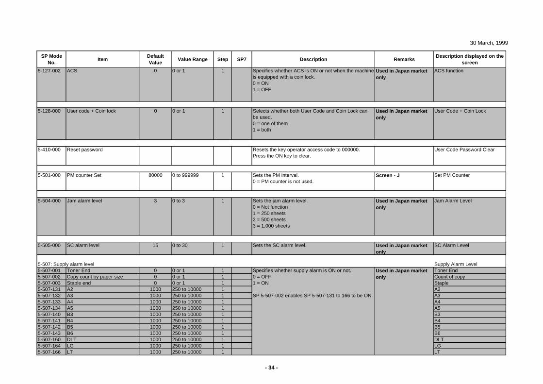
30 March, 1999
SP Mode No.
ItemDefault Value
Value Range Step SP7 Description RemarksDescription displayed on the
screen
5-127-002 ACS 0 0 or 1 1 Specifies whether ACS is ON or not when the machine is equipped with a coin lock.0 = ON1 = OFF
Used in Japan market only
ACS function
5-128-000 User code + Coin lock 0 0 or 1 1 Selects whether both User Code and Coin Lock can be used.0 = one of them1 = both
Used in Japan market only
User Code + Coin Lock
5-410-000 Reset password Resets the key operator access code to 000000.Press the ON key to clear.
User Code Password Clear
5-501-000 PM counter Set 80000 0 to 999999 1 Sets the PM interval.0 = PM counter is not used.
Screen - J Set PM Counter
5-504-000 Jam alarm level 3 0 to 3 1 Sets the jam alarm level.0 = Not function1 = 250 sheets2 = 500 sheets3 = 1,000 sheets
Used in Japan market only
Jam Alarm Level
5-505-000 SC alarm level 15 0 to 30 1 Sets the SC alarm level. Used in Japan market onl y
SC Alarm Level
5-507: Supply alarm level Supply Alarm Level5-507-001 Toner End 0 0 or 1 1 Toner End5-507-002 Copy count by paper size 0 0 or 1 1 Count of copy5-507-003 Staple end 0 0 or 1 1 Staple5-507-131 A2 1000 250 to 10000 1 A25-507-132 A3 1000 250 to 10000 1 A35-507-133 A4 1000 250 to 10000 1 A45-507-134 A5 1000 250 to 10000 1 A55-507-140 B3 1000 250 to 10000 1 B35-507-141 B4 1000 250 to 10000 1 B45-507-142 B5 1000 250 to 10000 1 B55-507-143 B6 1000 250 to 10000 1 B65-507-160 DLT 1000 250 to 10000 1 DLT5-507-164 LG 1000 250 to 10000 1 LG5-507-166 LT 1000 250 to 10000 1 LT
Specifies whether supply alarm is ON or not. 0 = OFF1 = ON
SP 5-507-002 enables SP 5-507-131 to 166 to be ON.
Used in Japan market only
- 34 -
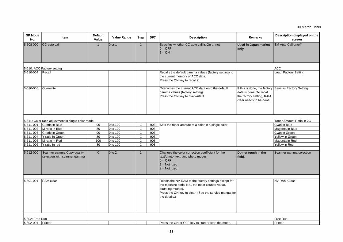
30 March, 1999
SP Mode No.
ItemDefault Value
Value Range Step SP7 Description RemarksDescription displayed on the
screen
5-508-000 CC auto call 1 0 or 1 1 Specifies whether CC auto call is On or not.0 = OFF1 = ON
Used in Japan market only
EM Auto Call on/off
5-610: ACC Factory setting ACC5-610-004 Recall Recalls the default gamma values (factory setting) to
the current memory of ACC data.Press the ON key to recall it.
Load: Factory Setting
5-610-005 Overwrite Overwrites the current ACC data onto the default gamma values (factory setting).Press the ON key to overwrite it.
If this is done, the factory data is gone. To recall the factory setting, RAM clear needs to be done.
Save as Factory Setting
5-611: Color ratio adjustment in single color mode Toner Amount Ratio in 2C5-611-001 C ratio in Blue 90 0 to 100 1 903 Cyan in Blue5-611-002 M ratio in Blue 80 0 to 100 1 903 Magenta in Blue5-611-003 C ratio in Green 90 0 to 100 1 903 Cyan in Green5-611-004 Y ratio in Green 80 0 to 100 1 903 Yellow in Green5-611-005 M ratio in Red 100 0 to 100 1 903 Magenta in Red5-611-006 Y ratio in red 80 0 to 100 1 903 Yellow in Red
5-612-000 Scanner gamma Copy quality selection with scanner gamma
0 0 to 2 1 Changes the color correction coefficient for the text/photo, text, and photo modes.0 = OFF1 = Not fixed2 = Not fixed
Do not touch in the field.
Scanner gamma selection
5-801-001 RAM clear Resets the NV-RAM to the factory settings except for the machine serial No., the main counter value, counting method.Press the ON key to clear. (See the service manual for the details.)
NV RAM Clear
5-802: Free Run Free Run5-802-001 Printer PrinterPress the ON or OFF key to start or stop the mode.
Sets the toner amount of a color in a single color.
- 35 -
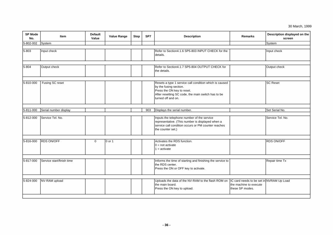
30 March, 1999
SP Mode No.
ItemDefault Value
Value Range Step SP7 Description RemarksDescription displayed on the
screen
5-802-002 System System
5-803 Input check Refer to Section4.1.6 SP5-803 INPUT CHECK for the details.
Input check
5-804 Output check Refer to Section4.1.7 SP5-804 OUTPUT CHECK for the details.
Output check
5-810-000 Fusing SC reset Resets a type 1 service call condition which is caused by the fusing section. Press the ON key to reset.After resetting SC code, the main switch has to be turned off and on.
SC Reset
5-811-000 Serial number display 903 Displays the serial number. Set Serial No.
5-812-000 Service Tel. No. Inputs the telephone number of the service representative. (This number is displayed when a service call condition occurs or PM counter reaches the counter set.)
Service Tel. No.
5-816-000 RDS ON/OFF 0 0 or 1 Activates the RDS function.0 = not activate1 = activate
RDS ON/OFF
5-817-000 Service start/finish time Informs the time of starting and finishing the service to the RDS center.Press the ON or OFF key to activate.
Repair time Tx
5-824-000 NV-RAM upload Uploads the data of the NV-RAM to the flash ROM on the main board. Press the ON key to upload.
IC card needs to be set in the machine to execute these SP modes.
NVRAM Up Load
- 36 -
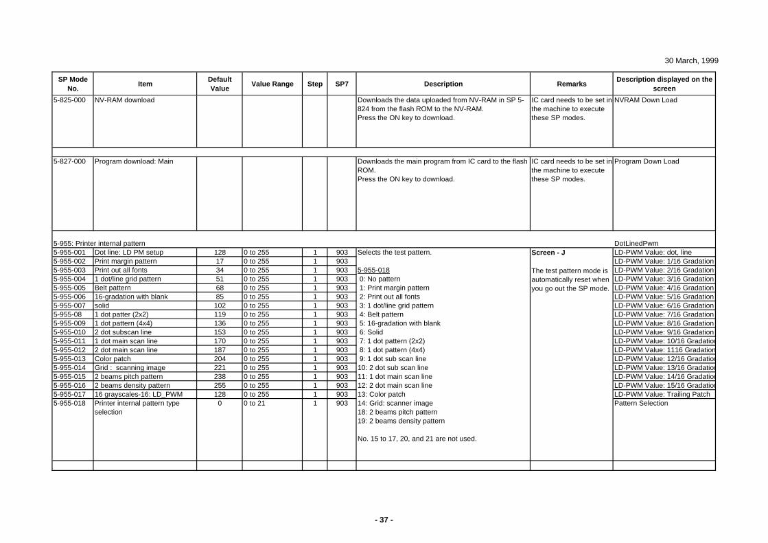
30 March, 1999
SP Mode No.
ItemDefault Value
Value Range Step SP7 Description RemarksDescription displayed on the
screen
5-825-000 NV-RAM download Downloads the data uploaded from NV-RAM in SP 5-824 from the flash ROM to the NV-RAM. Press the ON key to download.
IC card needs to be set in the machine to execute these SP modes.
NVRAM Down Load
5-827-000 Program download: Main Downloads the main program from IC card to the flash ROM. Press the ON key to download.
IC card needs to be set in the machine to execute these SP modes.
Program Down Load
5-955: Printer internal pattern DotLinedPwm5-955-001 Dot line: LD PM setup 128 0 to 255 1 903 LD-PWM Value: dot, line5-955-002 Print margin pattern 17 0 to 255 1 903 LD-PWM Value: 1/16 Gradation5-955-003 Print out all fonts 34 0 to 255 1 903 LD-PWM Value: 2/16 Gradation5-955-004 1 dot/line grid pattern 51 0 to 255 1 903 LD-PWM Value: 3/16 Gradation5-955-005 Belt pattern 68 0 to 255 1 903 LD-PWM Value: 4/16 Gradation5-955-006 16-gradation with blank 85 0 to 255 1 903 LD-PWM Value: 5/16 Gradation5-955-007 solid 102 0 to 255 1 903 LD-PWM Value: 6/16 Gradation5-955-08 1 dot patter (2x2) 119 0 to 255 1 903 LD-PWM Value: 7/16 Gradation5-955-009 1 dot pattern (4x4) 136 0 to 255 1 903 LD-PWM Value: 8/16 Gradation5-955-010 2 dot subscan line 153 0 to 255 1 903 LD-PWM Value: 9/16 Gradation5-955-011 1 dot main scan line 170 0 to 255 1 903 LD-PWM Value: 10/16 Gradation5-955-012 2 dot main scan line 187 0 to 255 1 903 LD-PWM Value: 1116 Gradation5-955-013 Color patch 204 0 to 255 1 903 LD-PWM Value: 12/16 Gradation5-955-014 Grid : scanning image 221 0 to 255 1 903 LD-PWM Value: 13/16 Gradation5-955-015 2 beams pitch pattern 238 0 to 255 1 903 LD-PWM Value: 14/16 Gradation5-955-016 2 beams density pattern 255 0 to 255 1 903 LD-PWM Value: 15/16 Gradation5-955-017 16 grayscales-16: LD_PWM 128 0 to 255 1 903 LD-PWM Value: Trailing Patch5-955-018 Printer internal pattern type
selection0 0 to 21 1 903 Pattern Selection
Screen - J
The test pattern mode is automatically reset when you go out the SP mode.
Selects the test pattern.
5-955-018 0: No pattern 1: Print margin pattern 2: Print out all fonts 3: 1 dot/line grid pattern 4: Belt pattern 5: 16-gradation with blank 6: Solid 7: 1 dot pattern (2x2) 8: 1 dot pattern (4x4) 9: 1 dot sub scan line10: 2 dot sub scan line11: 1 dot main scan line12: 2 dot main scan line13: Color patch14: Grid: scanner image18: 2 beams pitch pattern19: 2 beams density pattern
No. 15 to 17, 20, and 21 are not used.
- 37 -
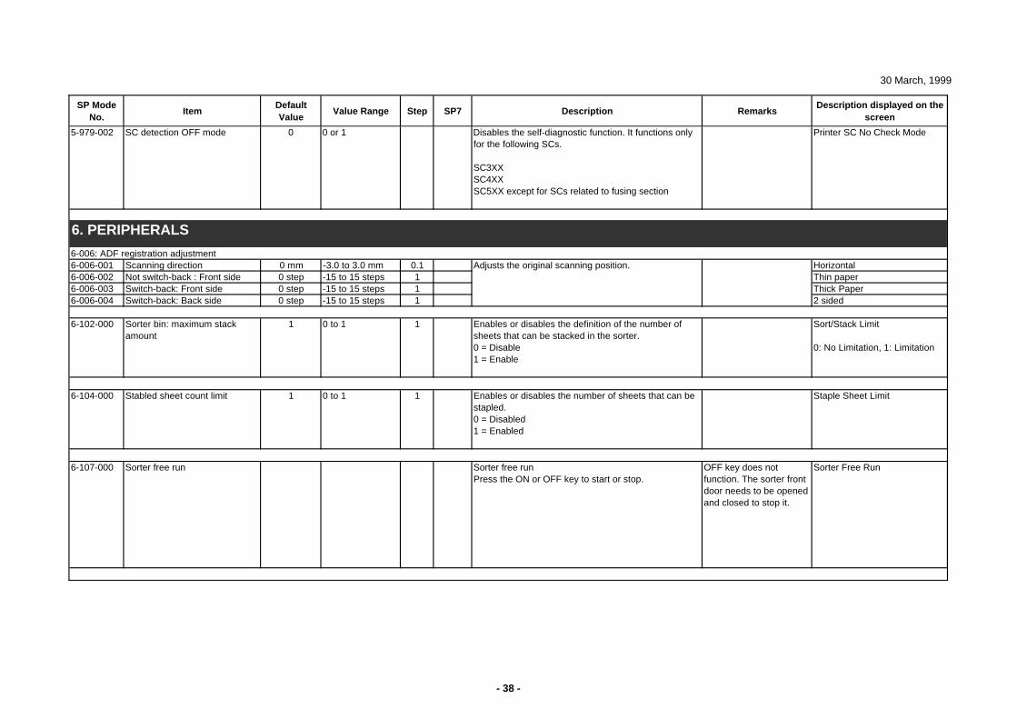
30 March, 1999
SP Mode No.
ItemDefault Value
Value Range Step SP7 Description RemarksDescription displayed on the
screen
5-979-002 SC detection OFF mode 0 0 or 1 Disables the self-diagnostic function. It functions only for the following SCs.
SC3XXSC4XXSC5XX except for SCs related to fusing section
Printer SC No Check Mode
6 PERIPHERALS
6-006: ADF registration adjustment6-006-001 Scanning direction 0 mm -3.0 to 3.0 mm 0.1 Horizontal6-006-002 Not switch-back : Front side 0 step -15 to 15 steps 1 Thin paper6-006-003 Switch-back: Front side 0 step -15 to 15 steps 1 Thick Paper6-006-004 Switch-back: Back side 0 step -15 to 15 steps 1 2 sided
6-102-000 Sorter bin: maximum stack amount
1 0 to 1 1 Enables or disables the definition of the number of sheets that can be stacked in the sorter.0 = Disable1 = Enable
Sort/Stack Limit
0: No Limitation, 1: Limitation
6-104-000 Stabled sheet count limit 1 0 to 1 1 Enables or disables the number of sheets that can be stapled.0 = Disabled1 = Enabled
Staple Sheet Limit
6-107-000 Sorter free run Sorter free runPress the ON or OFF key to start or stop.
OFF key does not function. The sorter front door needs to be opened and closed to stop it.
Sorter Free Run
6. PERIPHERALS
Adjusts the original scanning position.
- 38 -
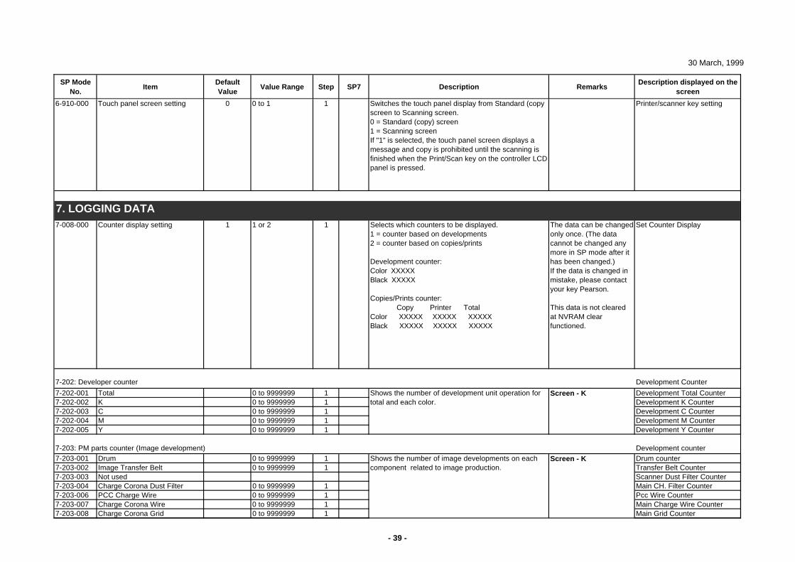
30 March, 1999
SP Mode No.
ItemDefault Value
Value Range Step SP7 Description RemarksDescription displayed on the
screen
6-910-000 Touch panel screen setting 0 0 to 1 1 Switches the touch panel display from Standard (copy screen to Scanning screen.0 = Standard (copy) screen1 = Scanning screen If "1" is selected, the touch panel screen displays a message and copy is prohibited until the scanning is finished when the Print/Scan key on the controller LCD panel is pressed.
Printer/scanner key setting
7-008-000 Counter display setting 1 1 or 2 1 Selects which counters to be displayed.1 = counter based on developments2 = counter based on copies/prints
Development counter:Color XXXXXBlack XXXXX
Copies/Prints counter: Copy Printer TotalColor XXXXX XXXXX XXXXXBlack XXXXX XXXXX XXXXX
The data can be changed only once. (The data cannot be changed any more in SP mode after it has been changed.)If the data is changed in mistake, please contact your key Pearson.
This data is not cleared at NVRAM clear functioned.
Set Counter Display
7-202: Developer counter Development Counter
7-202-001 Total 0 to 9999999 1 Development Total Counter7-202-002 K 0 to 9999999 1 Development K Counter7-202-003 C 0 to 9999999 1 Development C Counter7-202-004 M 0 to 9999999 1 Development M Counter7-202-005 Y 0 to 9999999 1 Development Y Counter
7-203: PM parts counter (Image development) Development counter7-203-001 Drum 0 to 9999999 1 Drum counter7-203-002 Image Transfer Belt 0 to 9999999 1 Transfer Belt Counter7-203-003 Not used Scanner Dust Filter Counter7-203-004 Charge Corona Dust Filter 0 to 9999999 1 Main CH. Filter Counter7-203-006 PCC Charge Wire 0 to 9999999 1 Pcc Wire Counter7-203-007 Charge Corona Wire 0 to 9999999 1 Main Charge Wire Counter7-203-008 Charge Corona Grid 0 to 9999999 1 Main Grid Counter
Shows the number of development unit operation for total and each color.
Screen - K
Screen - K
Shows the number of image developments on each component related to image production.
7. LOGGING DATA
- 39 -
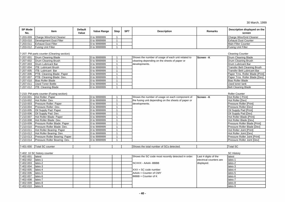
30 March, 1999
SP Mode No.
ItemDefault Value
Value Range Step SP7 Description RemarksDescription displayed on the
screen
7-203-009 Charge Wire/Grid Cleaner 0 to 9999999 1 Charge Wire/Grid Cleaner7-203-010 Development Dust Filter 0 to 9999999 1 Exhaust Dust Counter7-203-011 Exhaust Dust Filter 0 to 9999999 1 Main Filter Counter7-203-012 Fusing Unit Filter 0 to 9999999 1 Fusing Unit Filter
7-207: PM parts counter (Cleaning section) Cleaning Counter7-207-001 Drum Cleaning Blade 0 to 9999999 1 Drum Cleaning Blade7-207-002 Drum Cleaning Brush 0 to 9999999 1 Drum Cleaning Brush7-207-003 Drum Lubricant Bar 0 to 9999999 1 Drum Lubricant Bar7-207-004 ITB: Lubricant Brush 0 to 9999999 1 Transfer Belt Cleaning Brush7-207-005 ITB: Lubricant Bar 0 to 9999999 1 Transfer Belt Lubricant Bar7-207-006 PTB: Cleaning Blade: Paper 0 to 9999999 1 Paper Trns. Roller Blade [Print]7-207-007 PTB: Cleaning Blade: Dev.. 0 to 9999999 1 Paper Trns. Roller Blade [Dev]7-207-010 Bias Roller Blade 0 to 9999999 1 Bias Roller Blade7-207-011 Used Toner Bottle 0 to 9999999 1 Used toner tank7-207-012 ITB: Cleaning Blade 0 to 9999999 1 Belt Cleaning Blade
7-210: PM parts counter (Fusing section) Roller Counter7-210-001 Hot Roller: Paper 0 to 9999999 1 Hot Roller [ Print]7-210-002 Hot Roller: Dev. 0 to 9999999 1 Hot Roller [Dev]7-210-003 Pressure Roller: Paper 0 to 9999999 1 Pressure Roller [Print]7-210-004 Pressure Roller: Dev. 0 to 9999999 1 Pressure Roller [Dev]7-210-005 Oil Supply Pad: Paper 0 to 9999999 1 Oil Supply Pad [Print]7-210-006 Oil Supply Pad: Dev. 0 to 9999999 1 Oil Supply Pad [Dev]7-210-007 Hot Roller Blade: Paper 0 to 9999999 1 Hot Roller Blade [Print]7-210-008 Hot Roller Blade: Dev. 0 to 9999999 1 Hot Roller Blade [Dev]7-210-009 Pressure Roller Blade: Paper 0 to 9999999 1 Pressure Roller Blade [Print]7-210-010 Pressure Roller Blade: Dev. 0 to 9999999 1 Pressure Roller Blade [Dev]7-210-011 Hot Roller Bearing: Paper 0 to 9999999 1 Hot Roller Joint [Print]7-210-012 Hot Roller Bearing: Dev. 0 to 9999999 1 Hot Roller Joint [Dev]7-210-013 Pressure Roller Bearing: Paper 0 to 9999999 1 Pressure Roller Joint [Print]7-210-014 Pressure Roller Bearing: Dev. 0 to 9999999 1 Pressure Roller Joint [Dev]
7-401-000 Total SC counter Shows the total number of SCs detected. Total SC
7-402: 10 SC history counter SC History7-402-001 latest latest7-402-002 lates-1 lates-17-402-003 lates-2 lates-27-402-004 lates-3 lates-37-402-005 lates-4 lates-47-402-006 lates-5 lates-57-402-007 lates-6 lates-67-402-008 lates-7 lates-77-402-009 lates-8 lates-87-402-010 lates-9 lates-9
Shows the number of usage of each unit related to cleaning depending on the sheets of paper or developments.
Shows the SC code most recently detected in order.
SCXXX - AAAA -BBBB
XXX = SC code numberAAAA = Counter of CMYBBBB = Counter of K
Screen - K
Screen - KShows the number of usage on each component of the fusing unit depending on the sheets of paper or developments.
Last 4 digits of the electrical counters are displayed.
- 40 -
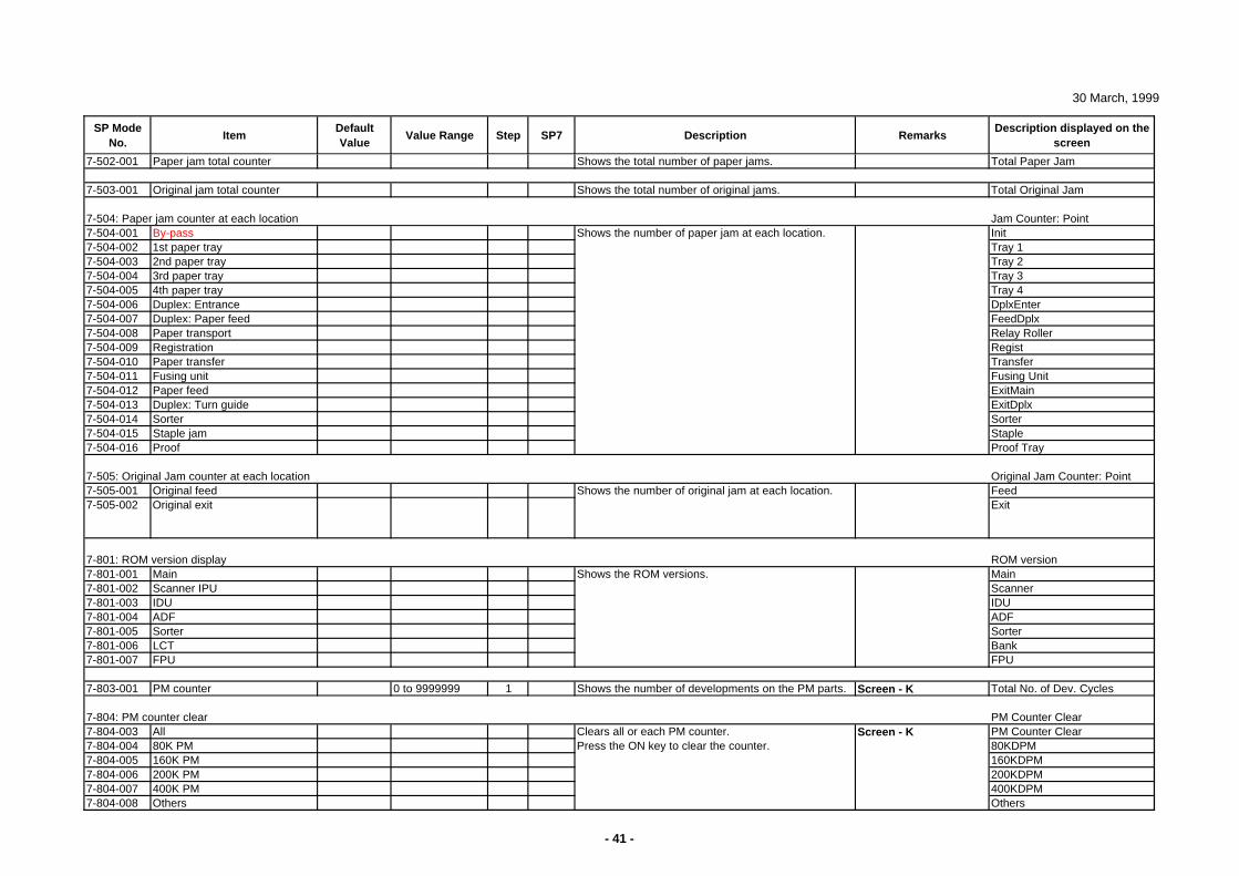
30 March, 1999
SP Mode No.
ItemDefault Value
Value Range Step SP7 Description RemarksDescription displayed on the
screen
7-502-001 Paper jam total counter Shows the total number of paper jams. Total Paper Jam
7-503-001 Original jam total counter Shows the total number of original jams. Total Original Jam
7-504: Paper jam counter at each location Jam Counter: Point7-504-001 By-pass Init7-504-002 1st paper tray Tray 17-504-003 2nd paper tray Tray 27-504-004 3rd paper tray Tray 37-504-005 4th paper tray Tray 47-504-006 Duplex: Entrance DplxEnter7-504-007 Duplex: Paper feed FeedDplx7-504-008 Paper transport Relay Roller7-504-009 Registration Regist7-504-010 Paper transfer Transfer7-504-011 Fusing unit Fusing Unit7-504-012 Paper feed ExitMain7-504-013 Duplex: Turn guide ExitDplx7-504-014 Sorter Sorter7-504-015 Staple jam Staple7-504-016 Proof Proof Tray
7-505: Original Jam counter at each location Original Jam Counter: Point7-505-001 Original feed Feed7-505-002 Original exit Exit
7-801: ROM version display ROM version7-801-001 Main Main7-801-002 Scanner IPU Scanner7-801-003 IDU IDU7-801-004 ADF ADF7-801-005 Sorter Sorter7-801-006 LCT Bank7-801-007 FPU FPU
7-803-001 PM counter 0 to 9999999 1 Shows the number of developments on the PM parts. Screen - K Total No. of Dev. Cycles
7-804: PM counter clear PM Counter Clear7-804-003 All PM Counter Clear7-804-004 80K PM 80KDPM7-804-005 160K PM 160KDPM7-804-006 200K PM 200KDPM7-804-007 400K PM 400KDPM7-804-008 Others Others
Shows the number of original jam at each location.
Clears all or each PM counter.Press the ON key to clear the counter.
Screen - K
Shows the number of paper jam at each location.
Shows the ROM versions.
- 41 -
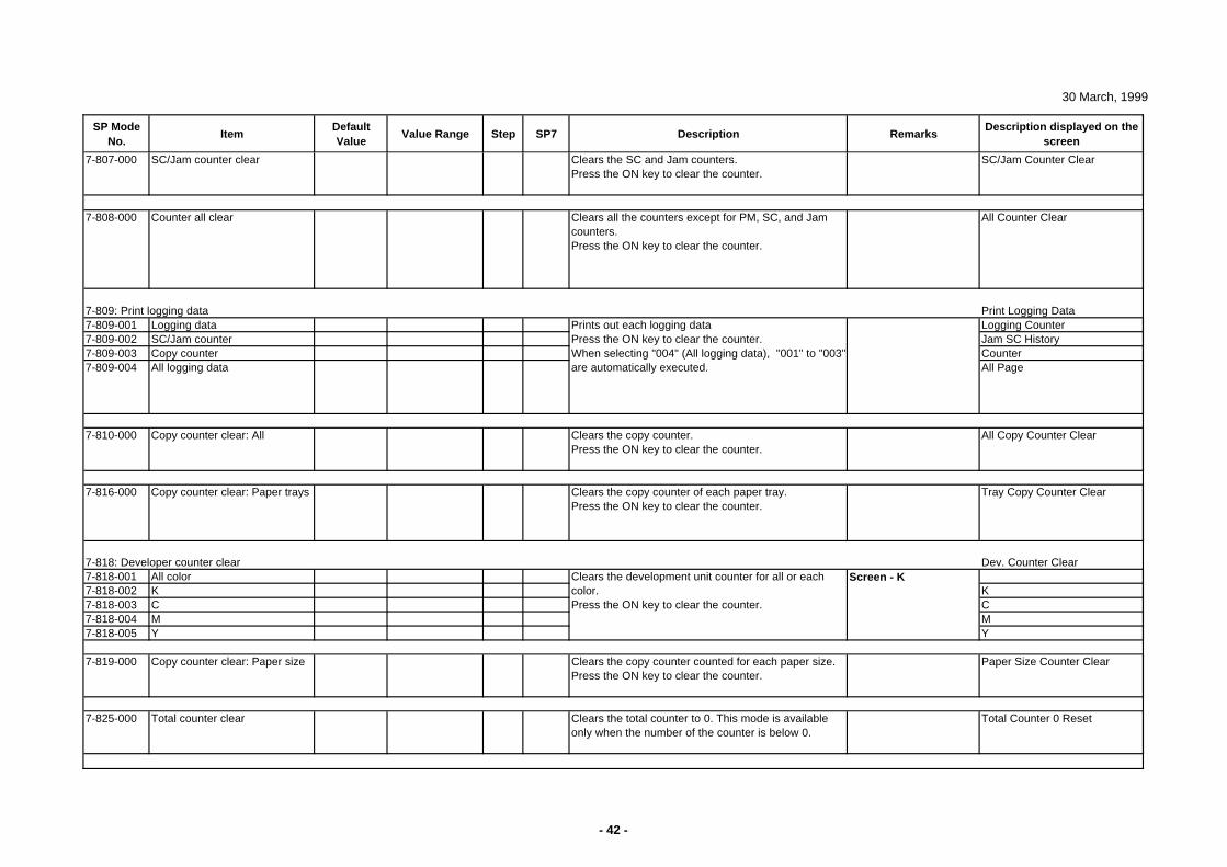
30 March, 1999
SP Mode No.
ItemDefault Value
Value Range Step SP7 Description RemarksDescription displayed on the
screen
7-807-000 SC/Jam counter clear Clears the SC and Jam counters.Press the ON key to clear the counter.
SC/Jam Counter Clear
7-808-000 Counter all clear Clears all the counters except for PM, SC, and Jam counters.Press the ON key to clear the counter.
All Counter Clear
7-809: Print logging data Print Logging Data7-809-001 Logging data Logging Counter7-809-002 SC/Jam counter Jam SC History7-809-003 Copy counter Counter7-809-004 All logging data All Page
7-810-000 Copy counter clear: All Clears the copy counter.Press the ON key to clear the counter.
All Copy Counter Clear
7-816-000 Copy counter clear: Paper trays Clears the copy counter of each paper tray.Press the ON key to clear the counter.
Tray Copy Counter Clear
7-818: Developer counter clear Dev. Counter Clear7-818-001 All color 7-818-002 K K7-818-003 C C7-818-004 M M7-818-005 Y Y
7-819-000 Copy counter clear: Paper size Clears the copy counter counted for each paper size.Press the ON key to clear the counter.
Paper Size Counter Clear
7-825-000 Total counter clear Clears the total counter to 0. This mode is available only when the number of the counter is below 0.
Total Counter 0 Reset
Screen - KClears the development unit counter for all or each color.Press the ON key to clear the counter.
Prints out each logging dataPress the ON key to clear the counter.When selecting "004" (All logging data), "001" to "003" are automatically executed.
- 42 -
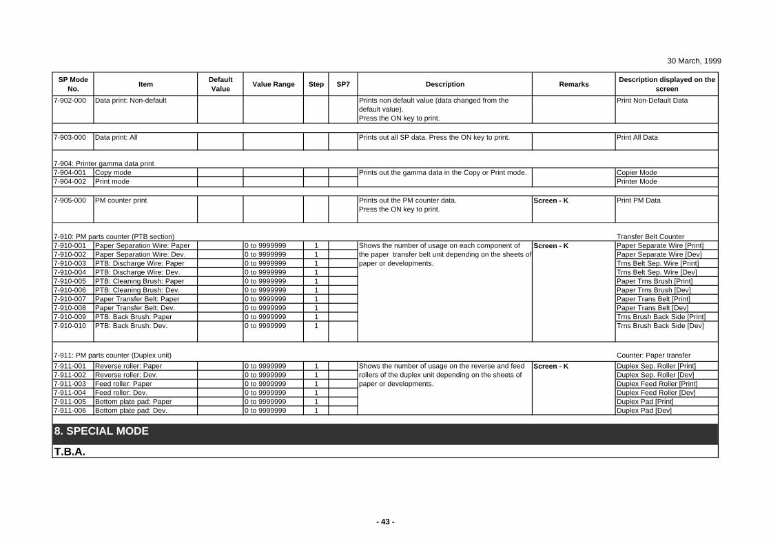
30 March, 1999
SP Mode No.
ItemDefault Value
Value Range Step SP7 Description RemarksDescription displayed on the
screen
7-902-000 Data print: Non-default Prints non default value (data changed from the default value).Press the ON key to print.
Print Non-Default Data
7-903-000 Data print: All Prints out all SP data. Press the ON key to print. Print All Data
7-904: Printer gamma data print7-904-001 Copy mode Copier Mode7-904-002 Print mode Printer Mode
7-905-000 PM counter print Prints out the PM counter data.Press the ON key to print.
Screen - K Print PM Data
7-910: PM parts counter (PTB section) Transfer Belt Counter7-910-001 Paper Separation Wire: Paper 0 to 9999999 1 Paper Separate Wire [Print]7-910-002 Paper Separation Wire: Dev. 0 to 9999999 1 Paper Separate Wire [Dev]7-910-003 PTB: Discharge Wire: Paper 0 to 9999999 1 Trns Belt Sep. Wire [Print]7-910-004 PTB: Discharge Wire: Dev. 0 to 9999999 1 Trns Belt Sep. Wire [Dev]7-910-005 PTB: Cleaning Brush: Paper 0 to 9999999 1 Paper Trns Brush [Print]7-910-006 PTB: Cleaning Brush: Dev. 0 to 9999999 1 Paper Trns Brush [Dev]7-910-007 Paper Transfer Belt: Paper 0 to 9999999 1 Paper Trans Belt [Print]7-910-008 Paper Transfer Belt: Dev. 0 to 9999999 1 Paper Trans Belt [Dev]7-910-009 PTB: Back Brush: Paper 0 to 9999999 1 Trns Brush Back Side [Print]7-910-010 PTB: Back Brush: Dev. 0 to 9999999 1 Trns Brush Back Side [Dev]
7-911: PM parts counter (Duplex unit) Counter: Paper transfer
7-911-001 Reverse roller: Paper 0 to 9999999 1 Duplex Sep. Roller [Print]7-911-002 Reverse roller: Dev. 0 to 9999999 1 Duplex Sep. Roller [Dev]7-911-003 Feed roller: Paper 0 to 9999999 1 Duplex Feed Roller [Print]7-911-004 Feed roller: Dev. 0 to 9999999 1 Duplex Feed Roller [Dev]7-911-005 Bottom plate pad: Paper 0 to 9999999 1 Duplex Pad [Print]7-911-006 Bottom plate pad: Dev. 0 to 9999999 1 Duplex Pad [Dev]
T.B.A.
Shows the number of usage on each component of the paper transfer belt unit depending on the sheets of paper or developments.
8. SPECIAL MODE
Screen - K
Screen - K
Shows the number of usage on the reverse and feed rollers of the duplex unit depending on the sheets of paper or developments.
Prints out the gamma data in the Copy or Print mode.
- 43 -

APPENDIX-3
POP-UP DISPLAYS
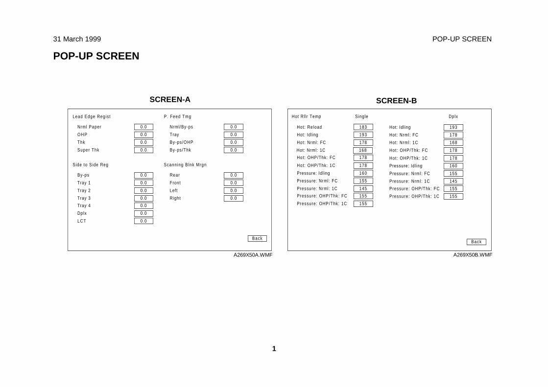
31 March 1999 POP-UP SCREEN
1
POP-UP SCREEN
Hot: Reload
Hot: Idl ing
Hot: Nrml: FC
Hot : OHP/Thk: FC
Back
183
193
178
178
Hot : OHP/Thk: 1C
Pressure: Idl ing
Pressure: Nrml : FC
Pressure: Nrml : 1C
178
160
155
145
Pressure: OHP/Thk: FC
Pressure: OHP/Thk: 1C
155
155
Hot: Idl ing
Hot: Nrml: FC
Hot: Nrml: 1C
Hot : OHP/Thk: FC
193
178
168
178
Hot : OHP/Thk: 1C
Pressure: Idl ing
Pressure: Nrml : FC
Pressure: Nrml : 1C
178
160
155
145
Pressure: OHP/Thk: FC
Pressure: OHP/Thk: 1C
155
155
Hot: Nrml: 1C 168
Hot Rl l r Temp Single Dplx
A269X50B.WMF
Nrml Paper
O H P
Thk
Super Thk
0.0
0.0
0.0
0.0
Back
0.0
0.0
0.0
0.0
Nrml /By-ps
Tray
By-ps /OHP
By-ps/Thk
Scanning Blnk MrgnSide to Side Reg
By-ps
Tray 1
Tray 2
Tray 3
0.0
0.0
0.0
0.0
0.0
0.0
0.0
0.0
Rear
Front
Left
Right
Tray 4
Dplx
L C T
0.0
0.0
0.0
Lead Edge Regis t P. Feed Tmg
A269X50A.WMF
SCREEN-A SCREEN-B
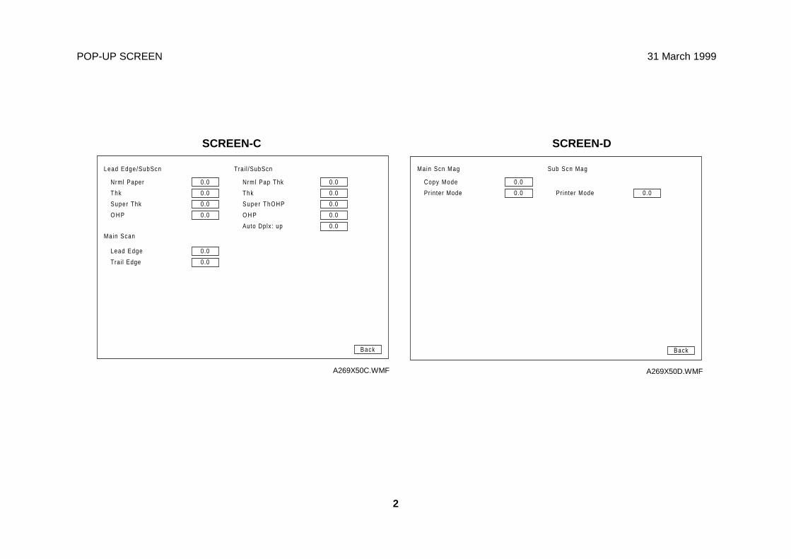
POP-UP SCREEN 31 March 1999
2
Printer Mode 0.0
Back
0.0
0.0 Pr inter Mode
Main Scn Mag Sub Scn Mag
Copy Mode
A269X50D.WMF
Thk
Super Thk
O H P
0.0
0.0
0.0
0.0
Back
0.0
0.0
0.0
0.0
Nrml Pap Thk
Thk
Super ThOHP
O H P
Main Scan
Lead Edge
Trai l Edge
0.0
0.0
0.0
Auto Dplx: up
Lead Edge/SubScn Trai l /SubScn
Nrml Paper
A269X50C.WMF
SCREEN-C SCREEN-D
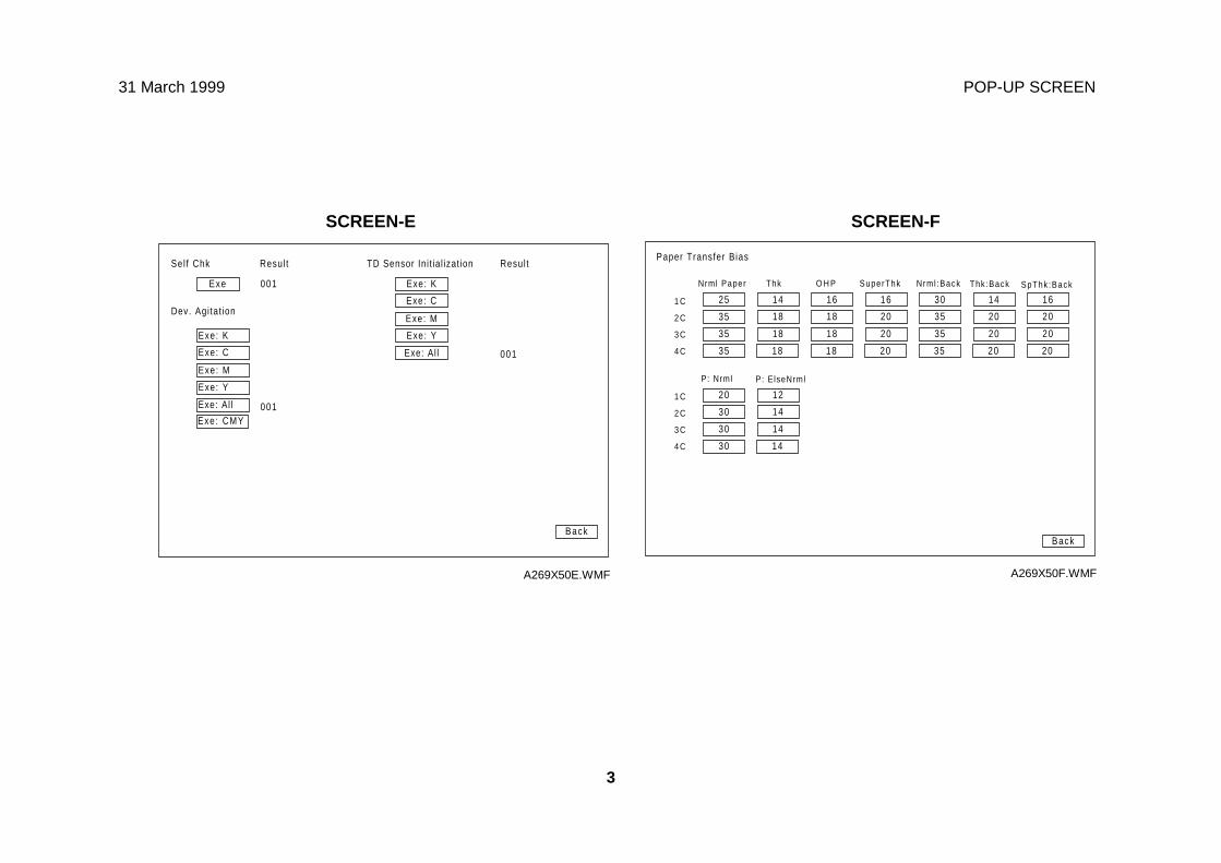
31 March 1999 POP-UP SCREEN
3
Exe: C
Back
Exe
Sel f Chk TD Sensor Ini t ial izat ion
Dev. Agi tat ion
Exe: K
Exe: Y
Exe: M
Exe: Al lExe: C
Exe: K
Exe: Y
Exe: M
Exe: Al l
Exe : CMY
Resul t
001
001
001
Resul t
A269X50E.WMF
Back
25
Paper Transfer Bias
Nrml Paper
14 16 16 30 14 16
Thk O H P SuperThk Nrml :Back Thk:Back SpThk :Back
1 C
35 18 18 20 35 20 20
35 18 18 20 35 20 20
2 C
3 C
4 C 35 18 18 20 35 20 20
20 121 C
30 14
30 14
2 C
3 C
4 C 30 14
P: Nrml P: ElseNrml
A269X50F.WMF
SCREEN-E SCREEN-F
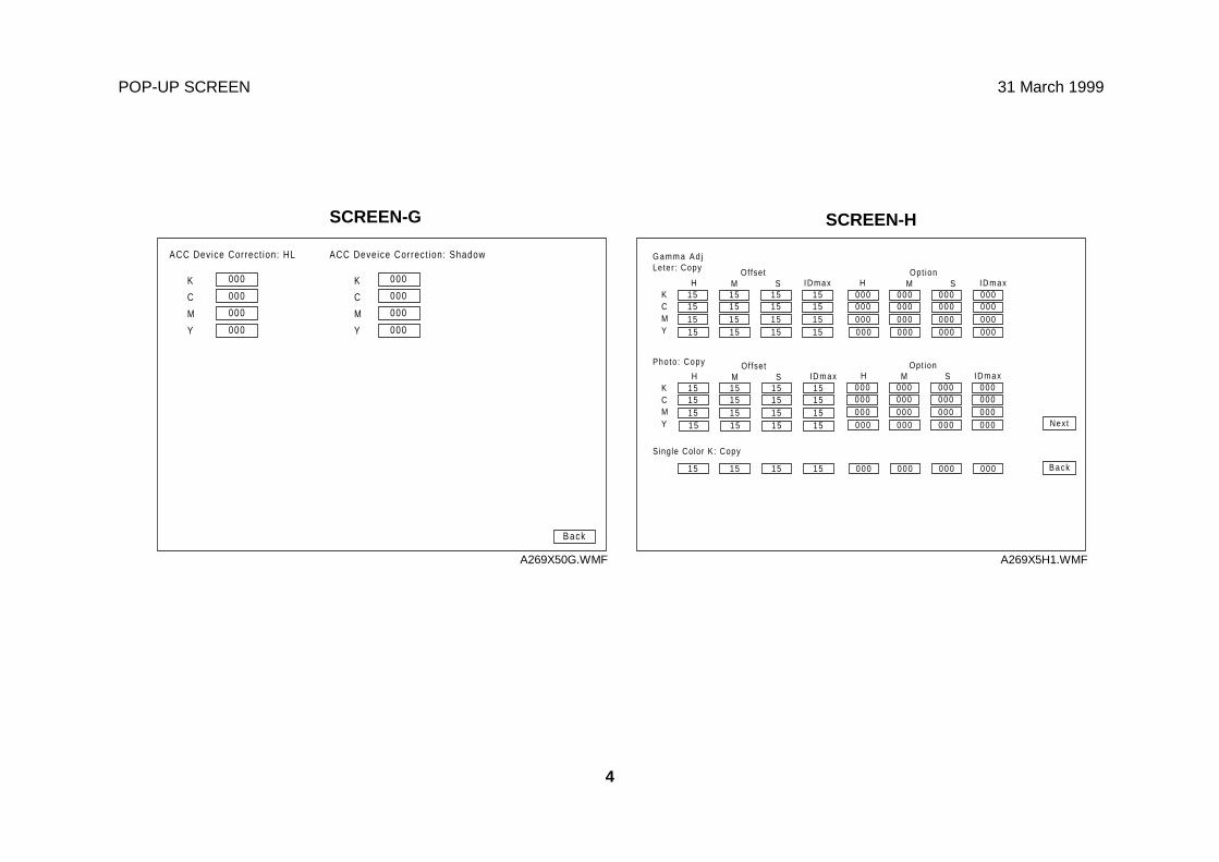
POP-UP SCREEN 31 March 1999
4
15
G a m m a A d jLeter : Copy
HKCMY
151515
15 15 1515 15 1515 15 1515 15 15
M S IDmaxOffset
15
Photo: Copy
HKCMY
151515
15 15 1515 15 1515 15 1515 15 15
M SOffset
15 15 15 15
Single Color K: Copy
IDmax
000H
000000000
000 000 000000 000 000000 000 000000 000 000
M S IDmaxOpt ion
000H
000000000
000 000 000000 000 000000 000 000000 000 000
M S IDmaxOpt ion
000 000 000000 Back
Next
A269X5H1.WMF
Back
000
ACC Device Correct ion: HL
000K
000 000
000 000
C
M
Y 000 000
K
C
M
Y
ACC Deveice Correct ion: Shadow
A269X50G.WMF
SCREEN-G SCREEN-H
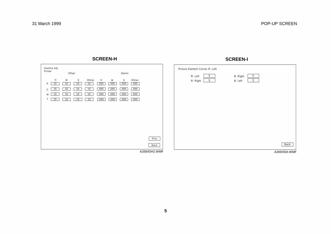
31 March 1999 POP-UP SCREEN
5
Back
5
Picture Element Correc R: Left
5R: Left
5 5R: Right
B: Right
B: Left
A269X50I.WMF
Back
15
G a m m a A d jPrinter
H
K
C
M
Y
15
15
15
15 15 15
15 15 15
15 15 15
15 15 15
M S
Offset
IDmax000H
000
000
000
000 000 000
000 000 000
000 000 000
000 000 000
M S IDmax
Opt ion
Prev
A269X5H2.WMF
SCREEN-ISCREEN-H
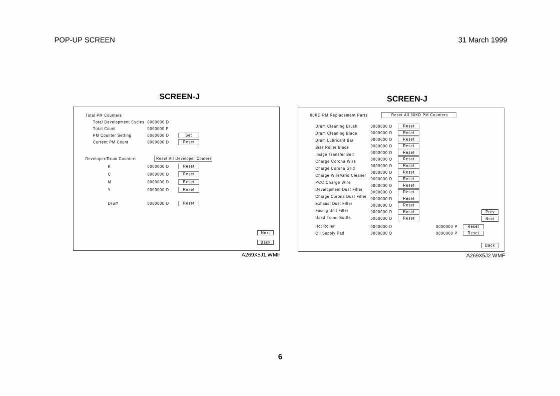
POP-UP SCREEN 31 March 1999
6
Back
Tota l PM Counters
Tota l Development Cyc les
Total Count
PM Counter Set t ing
Current PM Count
Deve loper /Drum Counters
K
C
M
Y
D r u m
Reset0000000 D
0000000 D
0000000 D
0000000 D
0000000 D
Reset Al l Developer Couters
0000000 D
0000000 P
0000000 D
0000000 D
Reset
Reset
Reset
Reset
Reset
Set
Next
A269X5J1.WMF
Back
80KD PM Rep lacement Par ts
Drum Cleaning Brush
Drum Cleaning B lade
Drum Lubr icant Bar
Bias Rol ler Blade
Image Transfer Bel t
Charge Corona Wi re
Charge Corona Gr id
Charge Wire/Gr id Cleaner
PCC Charge Wi re
Development Dust F i l ter
Charge Corona Dust F i l ter
Exhaust Dust Fi l ter
Fusing Unit Fi l ter
Used Toner Bot t le
0000000 D
0000000 D
0000000 D
0000000 D
0000000 D
0000000 D
0000000 D
0000000 D
0000000 D
0000000 D
0000000 D
0000000 D
0000000 D
0000000 D
Reset A l l 80KD PM Counters
Hot Rol ler
0000000 D
0000000 P Reset
Oi l Supply Pad 0000000 D 0000000 P Reset
Reset
Reset
Reset
Reset
Reset
Reset
Reset
Reset
Reset
Reset
Reset
Reset
Reset
Reset
Reset
0000000 D
Next
Prev
A269X5J2.WMF
SCREEN-J SCREEN-J
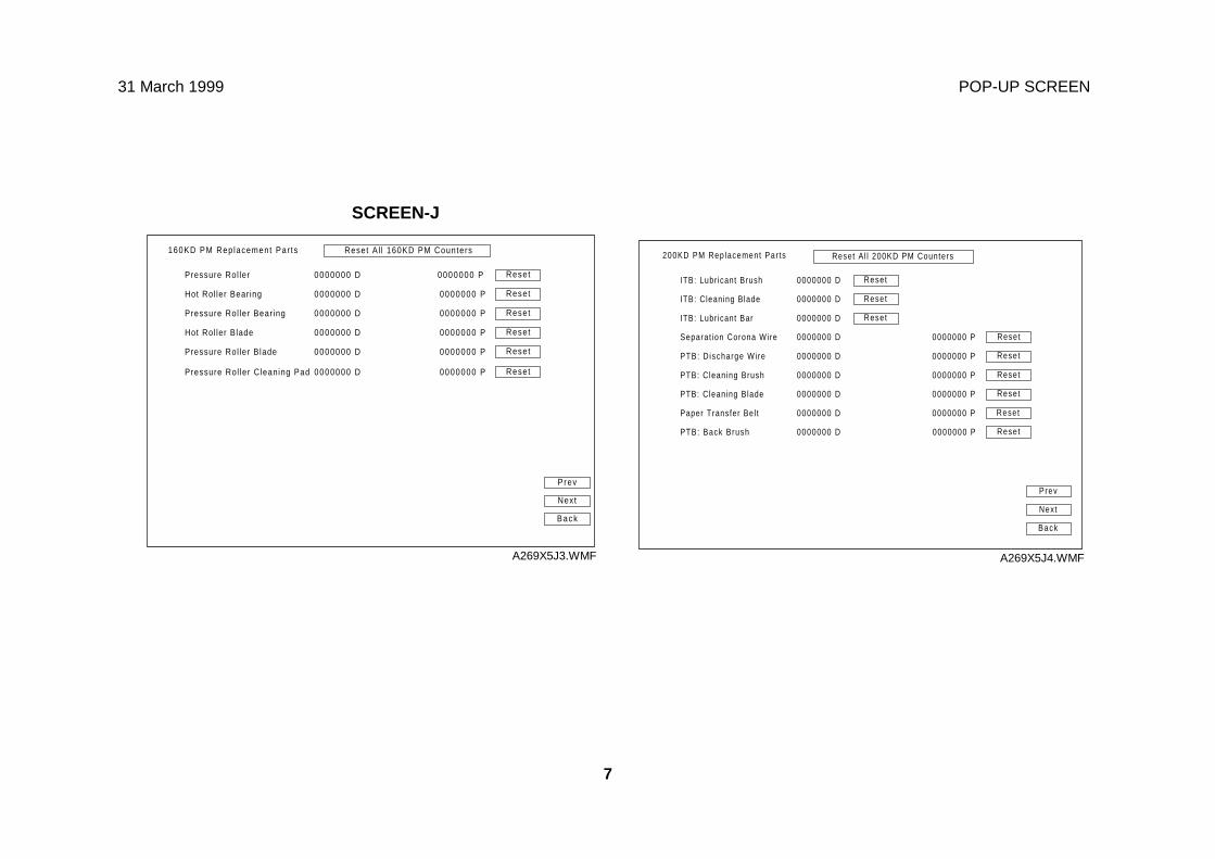
31 March 1999 POP-UP SCREEN
7
160KD PM Rep lacement Par ts
Pressure Rol ler
Hot Rol ler Bear ing
Pressure Rol ler Bear ing
Hot Rol ler Blade
Pressure Rol ler Blade
Pressure Rol ler Cleaning Pad
0000000 D
0000000 D
0000000 D
0000000 D
0000000 D
0000000 D
Reset A l l 160KD PM Counters
0000000 P
0000000 P
0000000 P
0000000 P
0000000 P
0000000 P
Reset
Reset
Reset
Reset
Reset
Reset
Back
Next
Prev
A269X5J3.WMF
200KD PM Replacement Par ts
ITB: Lubr icant Brush
ITB: Cleaning Blade
ITB: Lubr icant Bar
Separat ion Corona Wire
PTB: D ischarge Wire
PTB: Cleaning Brush
PTB: Cleaning Blade
Paper Transfer Bel t
PTB: Back Brush
0000000 D
0000000 D
0000000 D
0000000 D
0000000 D
0000000 D
0000000 D
0000000 D
0000000 D
0000000 P
0000000 P
0000000 P
0000000 P
Reset Al l 200KD PM Counters
Reset
Reset
Reset
Reset
Back
Reset
Reset
Reset0000000 P
Reset0000000 P
Reset
Next
Prev
A269X5J4.WMF
SCREEN-J
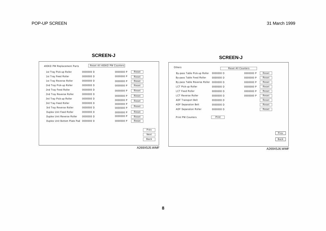
POP-UP SCREEN 31 March 1999
8
Prev
Others
By-pass Table Pick-up Rol ler
By-pass Table Feed Rol ler
By-pass Table Reverse Rol ler
LCT Pick-up Rol ler
LCT Feed Rol ler
0000000 D
0000000 D
0000000 D
0000000 D
0000000 D
0000000 D
0000000 D
0000000 P
0000000 P
0000000 P
0000000 P
0000000 P
Reset Al l Counters
LCT Reverse Rol ler
ADF Transport Bel t
ADF Separat ion Bel t
ADF Separat ion Rol ler
Pr int PM Counters
0000000 D
Reset
Reset
Reset
Reset
Reset
Reset
Reset
Reset
0000000 D
0000000 P Reset
Back
A269X5J6.WMF
400KD PM Rep lacement Par ts
1st Tray Feed Rol ler
1st Tray Reverse Rol ler
2nd Tray Pick-up Rol ler
2nd Tray Feed Rol ler
2nd Tray Reverse Rol ler
3rd Tray Pick-up Rol ler
3rd Tray Feed Rol ler
3rd Tray Reverse Rol ler
Duplex Uni t Feed Rol ler
Duplex Uni t Reverse Rol ler
Duplex Uni t Bot tom Plate Pad
1st Tray Pick-up Rol ler
Reset A l l 400KD PM Counters
0000000 D
0000000 D
0000000 D
0000000 D
0000000 D
0000000 D
0000000 D
0000000 D
0000000 D
0000000 P
0000000 P
0000000 P
0000000 P
Reset
Reset
Reset
Reset0000000 P
Reset0000000 P
Reset
0000000 D
0000000 D
0000000 D
0000000 P
0000000 P
0000000 P
0000000 P
0000000 P
0000000 P
Reset
Reset
Reset
Reset
Reset
Back
Next
Prev
A269X5J5.WMF
SCREEN-JSCREEN-J
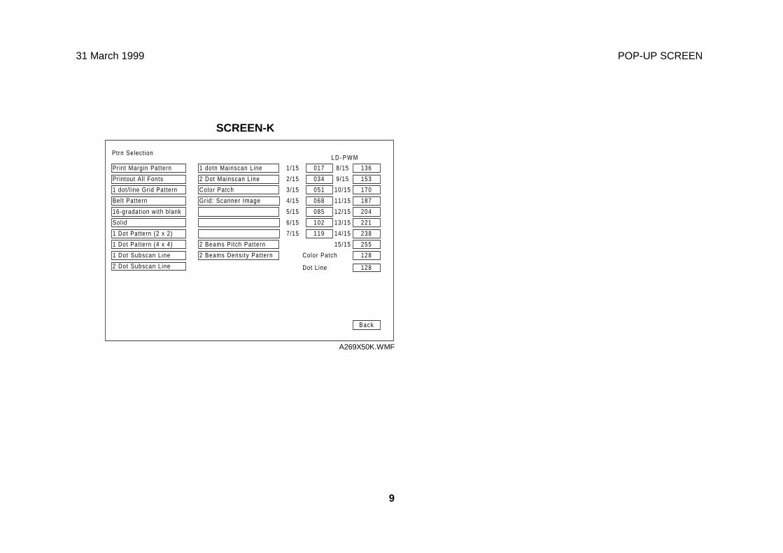
31 March 1999 POP-UP SCREEN
9
Ptrn Select ion
017
034
051
068
085
102
119
Back
Print Margin Pattern
2 Dot Subscan L ine
Printout Al l Fonts
1 dot/ l ine Grid Pattern
Belt Pattern
16-gradat ion with blank
Sol id
1 Dot Pattern (2 x 2)
1 Dot Pattern (4 x 4)
1 Dot Subscan L ine
1 dotn Mainscan Line
2 Dot Mainscan Line
Color Patch
Grid: Scanner Image
2 Beams Pi tch Pat tern
2 Beams Densi ty Pat tern
136
153
170
187
204
221
238
1/15
2/15
3/15
4/15
5/15
6/15
7/15
8/15
9/15
10/15
11/15
12/15
13/15
14/15
255
128
128
15/15
Color Patch
Dot Line
L D - P W M
A269X50K.WMF
SCREEN-K

APPENDIX-4
TIMING CHARTS
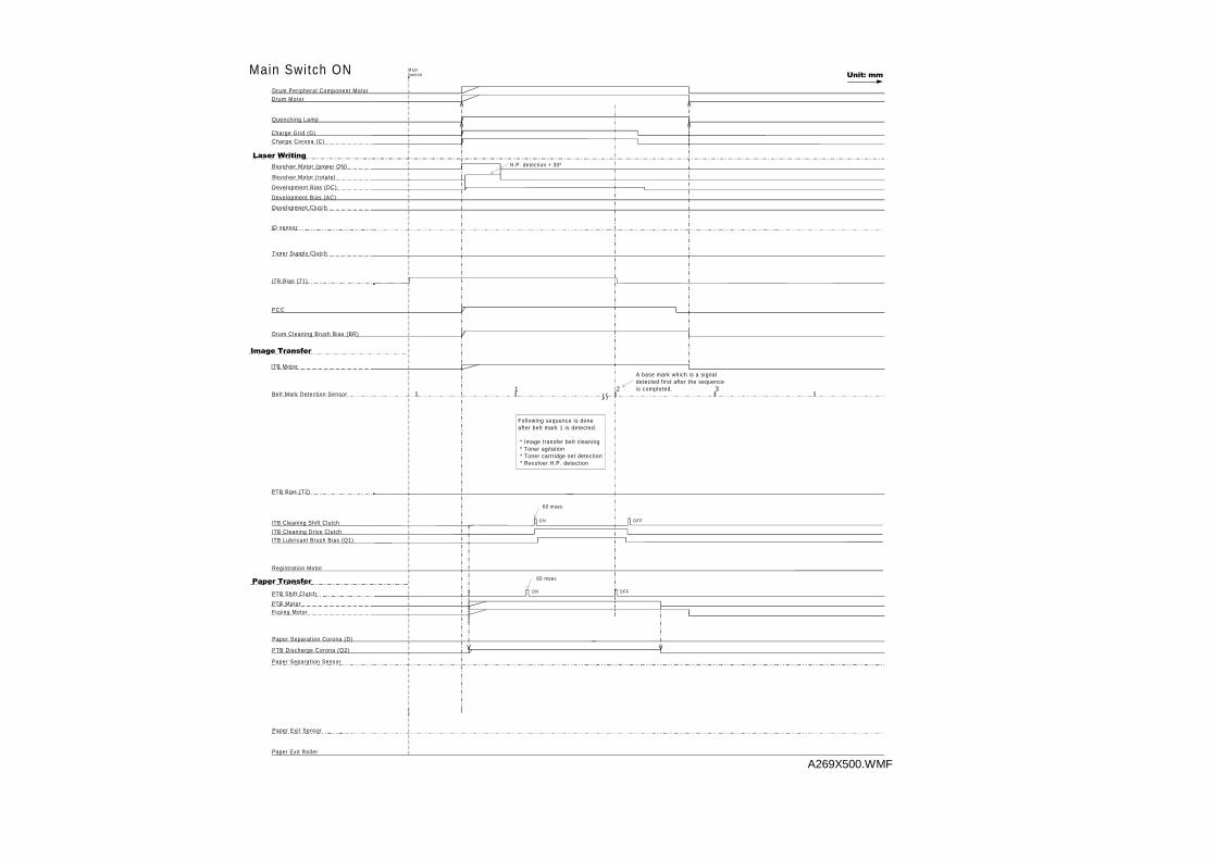
P C C
Drum Cleaning Brush Bias (BR)
Quenching Lamp
Charge Grid (G)
/DVHU#:ULWLQJ
Revolver Motor (rotate)
Development Bias (DC)
Development Bias (AC)
ID sensor
ITB Bias (T1)
Drum MotorDrum Peripheral Component Motor
,PDJH#7UDQVIHU
ITB Motor
Belt Mark Detection Sensor
PTB Bias (T2)
ITB Cleaning Shift Clutch
ITB Cleaning Drive Clutch
Paper Separat ion Corona (D)
Paper Separat ion Sensor
Paper Exit Sensor
Paper Exit Roller
Registration Motor
PTB Motor
PTB Discharge Corona (Q2)
Fusing Motor
M a i nSwi t chMain Switch ON
Charge Corona (C)
PTB Shift Clutch
Toner Supply Clutch
60 msec
60 msec
2 3
H.P. detection + 30º
Development Clutch
O F F
O F F
1
Revolver Motor (power ON)
ITB Lubricant Brush Bias (Q1)
3DSHU#7UDQVIHUO N
O N
Following sequence is done after belt mark 1 is detected.
* Image transfer belt cleaning * Toner agitation * Toner cartridge set detection * Revolver H.P. detection
A base mark which is a signaldetected first after the sequenceis completed.
8QLW=#PP
A269X500.WMF
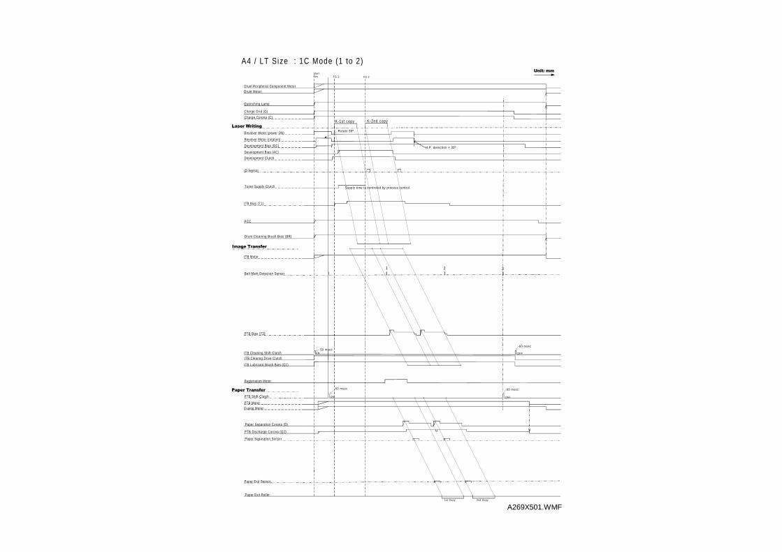
PCC
Drum Cleaning Brush Bias (BR)
Quenching Lamp
Charge Grid (G)
/DVHU#:ULWLQJ
Revolver Motor (rotation)
Development Bias (DC)
Development Bias (AC)
ID Sensor
ITB Bias (T1)
Drum MotorDrum Peripheral Component Motor
,PDJH#7UDQVIHU
ITB Motor
Belt Mark Detection Sensor
PTB Bias (T2)
ITB Cleaning Shift Clutch
ITB Cleanng Drive Clutch
Paper Separation Corona (D)
Paper Separation Sensor
Paper Exit Sensor
Paper Exit Roller
Registration Motor
PTB Motor
PTB Discharge Corona (Q2)
Fusing Motor
StartKey FG 1 FG 2
A4 / LT Size : 1C Mode (1 to 2)
Charge Corona (C)K-1st copy K-2nd copy
PTB Shift Clutch
Toner Supply Clutch
60 msec
50 msec
60 msec
1 2 3
H.P. detection + 30º
Development Clutch
60 msec
Supply time is controled by process control.
ON OFF
ON OFF
Rotate 30º
1st Copy 2nd Copy
Revolver Motor (power ON)
ITB Lubricant Brush Bias (Q1)
3DSHU#7UDQVIHU
8QLW=#PP
A269X501.WMF
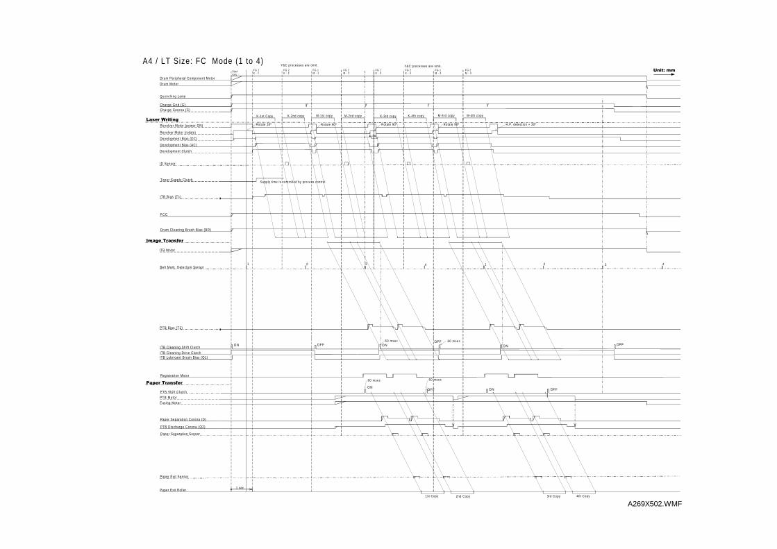
PCC
Drum Cleaning Brush Bias (BR)
Quenching Lamp
Charge Grid (G)
/DVHU#:ULWLQJ
Revolver Motor (rotate)
Development Bias (DC)
Development Bias (AC)
ID Sensor
ITB Bias (T1)
Drum Motor
Drum Peripheral Component Motor
,PDJH#7UDQVIHU
ITB Motor
Belt Mark Detection Sensor
PTB Bias (T2)
ITB Lubricant Brush Bias (Q1)
ITB Cleaning Shift Clutch
ITB Cleaning Drive Clutch
Paper Separation Corona (D)
Paper Separation Sensor
Paper Exit Sensor
Paper Exit Roller
Registration Motor
PTB Motor
PTB Discharge Corona (Q2)
Fusing Motor
StartKey
FG 1K - 1
A4 / LT Size: FC Mode (1 to 4)
Charge Corona (C)
K-1st Copy K-2nd copy
PTB Shift Clutch
Toner Supply Clutch
60 msec
Development Clutch
60 msec
FG 1M - 1
FG 2M - 2
M-1st copy M-2nd copy
60 msec
60 msec
Y&C processes are omit.
Supply time is controlled by process control.
Rotate 30º Rotate 90º
1 sec
K-3rd copy K-4th copy M-3rd copy M-4th copy
O NOFF
O NOFF
O N OFF
O N OFF
1st Copy 2nd Copy 3rd Copy 4th Copy
H.P. detection + 30ºRevolver Motor (power ON)
FG 2K - 2
FG 1K - 3
FG 2K - 4
FG 1M - 3
FG 2M - 4
3DSHU#7UDQVIHU
Rotate 90º Rotate 90º
Y&C processes are omit.
1 2 3 4 1 2 3 4
O N OFF
8QLW=#PP
A269X502.WMF
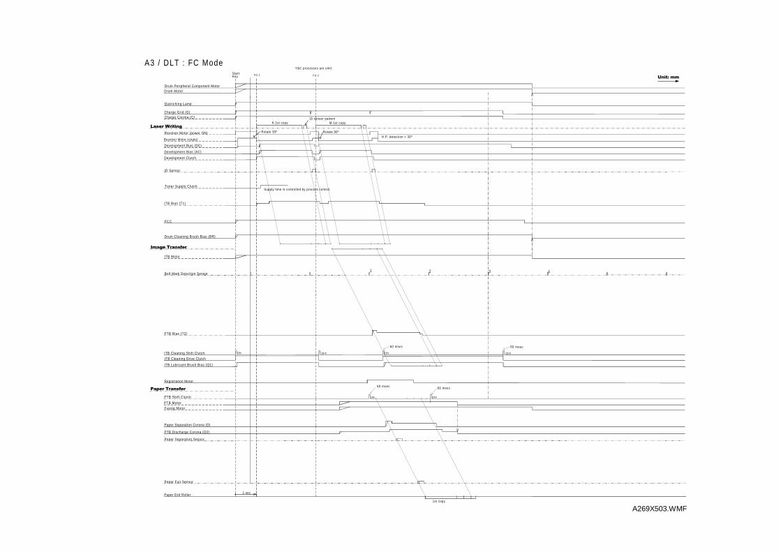
PCC
Drum Cleaning Brush Bias (BR)
Quenching Lamp
Charge Grid (G)
/DVHU#:ULWLQJ
Revolver Motor (rotate)
Development Bias (DC)
Development Bias (AC)
ID Sensor
ITB Bias (T1)
Drum MotorDrum Peripheral Component Motor
,PDJH#7UDQVIHU
ITB Motor
Belt Mark Detection Sensor
PTB Bias (T2)
ITB Cleaning Shift Clutch
ITB Cleaning Drive Clutch
Paper Separation Corona (D)
Paper Separation Sensor
Paper Exit Sensor
Paper Exit Roller
Registration Motor
PTB Motor
PTB Discharge Corona (Q2)
Fusing Motor
StartKey FG 1
A3 / DLT : FC Mode
Charge Corona (C)
PTB Shift Clutch
Toner Supply Clutch
60 msec
H.P. detection + 30º
Development Clutch
60 msec
FG 2
M-1st copy
3 42
60 msec
60 msec
Y&C processes are omit.
Supply time is controlled by process control.
Rotate 30º Rotate 90º
1 sec
ON OFF
ON OFF
1st copy
Revolver Motor (power ON)
ID sensor pattern
1
3DSHU#7UDQVIHU
ITB Lubricant Brush Bias (Q1)
ON OFF
8QLW=#PP
K-1st copy
A269X503.WMF
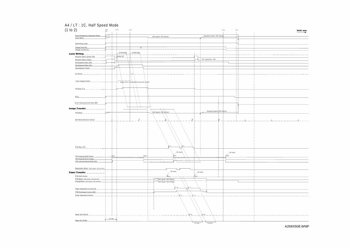
P C C
Drum Cleaning Brush Bias (BR)
Quehching Lamp
Charge Grid (G)
/DVHU#:ULWLQJ
Revolver Motor (rotate)
Development Bias (DC)
Development Bias (AC)
ID Sensor
ITB Bias (T1)
Drum MotorDrum Peripheral Component Motor
,PDJH#7UDQVIHU
ITB Motor
Belt Mark Detection Sensor
PTB Bias (T2)
ITB Cleaning Shift Clutch
ITB Cleaning Drive Clutch
Paper Separation Corona (D)
Paper Separation Sensor
Paper Exit Sensor
Paper Exit Roller
Registration Motor (Hal f speed: 100 mm/sec)
PTB Motor (Hal f speed: 100 mm/sec)
PTB Discharge Corona (Q2)
Fusing Motor (Hal f speed: 100 mm/sec)
StartKey
FG 1 FG 2
A4 / LT : 1C, Hal f Speed Mode(1 to 2)
Charge Corona (C)
K-1st copy K-2nd copy
PTB Shift Clutch
Toner Supply Clutch
60 msec
H.P. detection + 30º
Development Clutch
3 42
60 msec
Supply time is controlled by process control.
Rotate 30º
1.2 sec
ON OFF
ON OFF
1st copy 2nd copy
Half speed: 100 mm/sec
Half speed: 100 mm/sec
Half speed: 100 mm/sec
Revolver Motor (power ON)
Standard speed: 200 mm/sec
Standard speed: 200 mm/sec
FG 3 FG 4
3DSHU#7UDQVIHU
ITB Lubricant Brush Bias (Q1)
Half speed: 100 mm/sec
60 msec60 msec
1
ON OFF
8QLW=#PP
A269X508.WMF
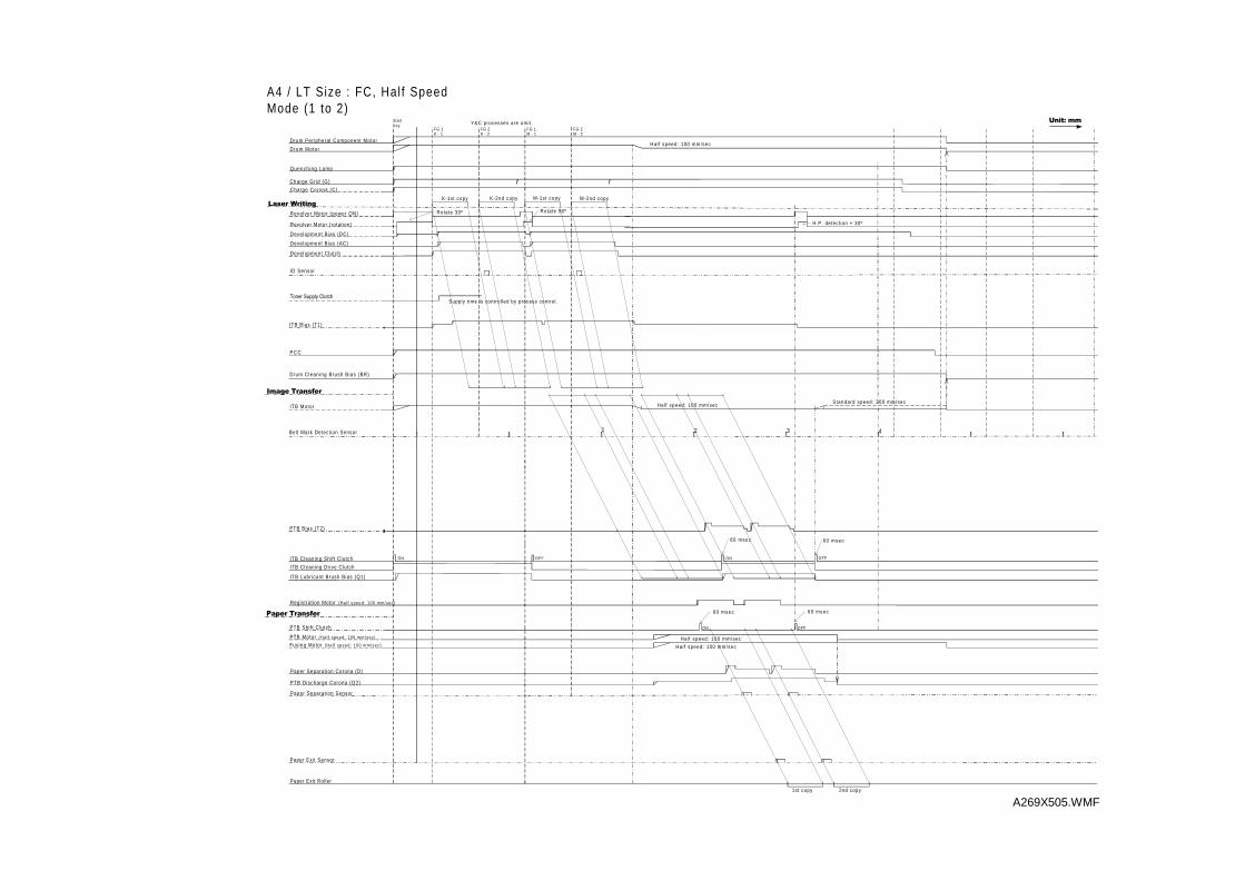
P C C
Drum Cleaning Brush Bias (BR)
Quench ing Lamp
Charge Gr id (G)
/DVHU#:ULWLQJ
Revolver Motor (rotat ion)
Development Bias (DC)
Development Bias (AC)
ID Sensor
ITB Bias (T1)
Drum Motor
Drum Per iphera l Component Motor
,PDJH#7UDQVIHU
ITB Motor
Bel t Mark Detect ion Sensor
PTB Bias (T2)
ITB Cleaning Shi f t Clutch
ITB Cleaning Drive Clutch
Paper Separat ion Corona (D)
Paper Separat ion Sensor
Paper Exit Sensor
Paper Exit Roller
Registrat ion Motor (Ha l f speed : 100 mm/sec )
PTB Motor (Ha l f speed : 100 mm/sec )
PTB Discharge Corona (Q2)
Fusing Motor (Ha l f speed : 100 mm/sec )
StartKey
FG 1K - 1
FG 2K - 2
A4 / LT Size : FC, Hal f SpeedMode (1 to 2)
Charge Corona (C)
K-1st copy K-2nd copy
PTB Shi f t Clutch
7RQHU#6XSSO\#&OXWFK
H.P. detect ion + 30º
Development Clutch
60 msec
FG 1M - 1
FG 2M - 2
M-1st copy M-2nd copy
3 42
60 msec
Y&C processes are omit .
Supply t ime is control led by process control.
Rotate 30º Rotate 90º
ON OFF
ON OFF
1st copy 2nd copy
Hal f speed: 100 mm/sec
Hal f speed: 100 mm/sec
Hal f speed: 100 mm/sec
Revolver Motor (power ON)
3DSHU#7UDQVIHU
ITB Lubr icant Brush Bias (Q1)
60 msec60 msec
Hal f speed: 100 mm/sec
1
Standard speed: 200 mm/sec
ON OFF
8QLW=#PP
A269X505.WMF
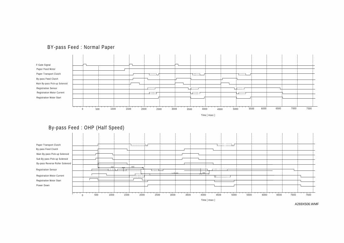
Main By-pass Pick-up Solenoid
By-pass Feed Clutch
Paper Transport Clutch
Paper Feed Motor
Registration Sensor
Registration Motor Start
Registration Motor Current
F-Gate Signal
1000 2000 3000 4000 5000500 1500 2500 3500 4500 5500
By-pass Reverse Roller Solenoid
Sub By-pass Pick-up Solenoid
By-pass Feed Clutch
Paper Transport Clutch
By-pass Feed : OHP (Half Speed)
Registration Sensor
Registration Motor Start
Registration Motor Current
Power Down
1000 2000 3000 4000 5000500 1500 2500 3500 4500 5500 6000
840 650
L-15 mm 280
0 6500 7000 7500
Main By-pass Pick-up Solenoid
BY-pass Feed : Normal Paper
6000 6500 7000 75000
Time [ msec ]
Time [ msec ]
A269X506.WMF
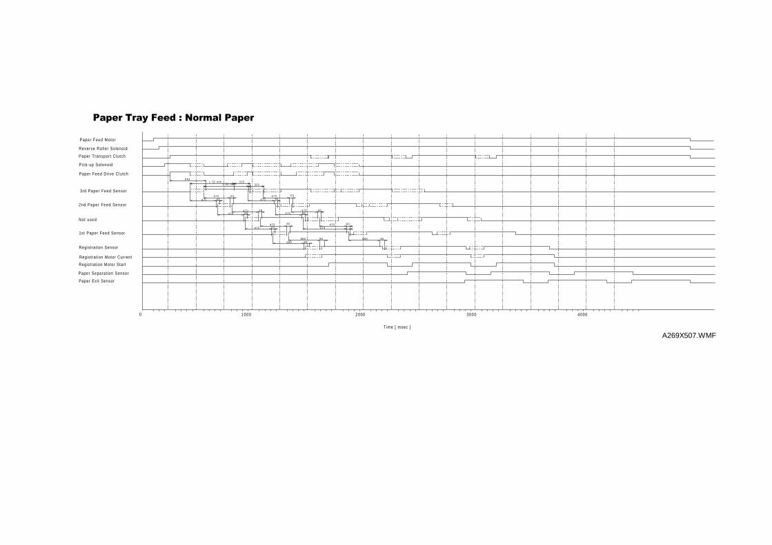
1000 2000 3000 4000
Paper Exit Sensor
Registration Motor Start
Registrat ion Motor Current
Paper Feed Drive Clutch
Pick-up Solenoid
Paper Transport Clutch
Paper Feed Motor
Reverse Rol ler Solenoid
1st Paper Feed Sensor
Not used
2nd Paper Feed Sensor
3rd Paper Feed Sensor
Registrat ion Sensor
6 4 4L - 5 2 m m
L - 5 2 m m3 2 5
3 2 5
4 7 0 6 06 04 7 0
4 7 04 7 0 6 0
6 0
4 7 04 7 0 6 0
6 0
4 7 04 7 0 6 0
6 0
4 7 04 7 06 0
6 0
4 7 04 7 0
6 0
5 6 05 6 0
9 09 0
6 6 0 9 0
3DSHU#7UD\#)HHG#=#1RUPDO#3DSHU
0
Time [ msec ]
Paper Separat ion Sensor
A269X507.WMF
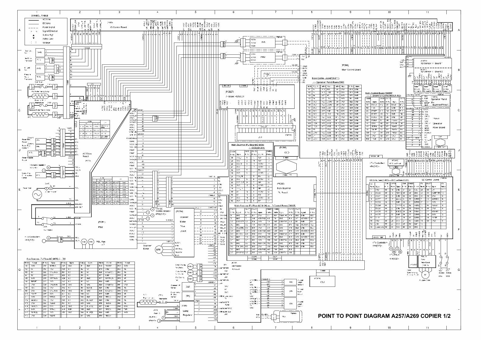
-1
-B7
-B2
-A7
FB_G
NC
V_SEN
FB_T2
-A8
ID_SEN1
(5)VCC1
CGND
(38)CGNDA
VMM1
CGNDA
VCC1A
CGNDA
CN218-3
(5)
-2
-B9
-B8
-B3
-B6
-A6
-A9
<
HUM_SEN
FB_BDC
-B1
-B5
-B4
-A5
-A4
LWHT_TH
FB_T1
UPHT_TH
ID_SEN2
TMP_SEN
4
6
2
12V
CNT
7
(S12)Toner
3
3
12V
T-SENC
Density Density
5
2
1 2
CGND
38
(S11)
1
4
Toner
CGND
T-SENM
1
-2 3
2
CGND
(S10)
2 CN2
(PCB16)
Toner
CGND
27
TD Sensor I/F Board 1
Toner(S9)
4
1
DensityDensity
3312V
2
1
654
CNT
TD Sensor I/F Board 2
12V
1
3
4
(PCB17)
8
T-SENY
T-SENK
3
4
1
CN1
-4
CNT
-1
BLTPTN
XZ_CROSS
VCC1A
-B11
CGND
CGND
DUP_CLK
-B6
XREV_HP
-B10
ENGY_ON
VCC1A
XLWHT_TRG
XUPHT_TRG
-B7
CGND
-3
CN353
4
2 1CNT
-A5
-B1
RGT_SEN
-A2
-A9
RM_B
RM_A
-B2
-A3
-B9
-A2
-B4
-B3
-B8
(5)
CN211-A1
(5)
-B5
VCC
GND
<
CGND
-A7
(-12)
-A8
RM_XB
RM_XA
-A11
VCB
-A6
-A3
-A4
XRGT_CL
CGND
VCA
-A10
(12)CGND
Sensor-M Sensor-C
(Option)
Signal
TXD3
RXD3
>
(5)
(5)
-5
-6
OPDI
VCC
-7
(for
RXD
VCA
-7
-8
Sensor-Y
-10-4
-3
CN11-1
-2
(5)
CN1-1
GND
-5
OPCLK
VCC-4
-5
OPDO
GND
RESET
CN314-5
-10
-11
-1
VCC
-12
-4
CN310-13
-4
-8
-3
(12)
-9
-2
-6
MAIN
-3
-9
GND
TXD-2
Sensor-K
>
-B2
P2AD0
-B4
P2AD2
GND
XPMSYNC1
-B1
P2AD4
-B3
<
CN311 68P
BLTPTN
<
-B5
XRESET
CN2
-B6
-4
-B10
-A1
-A5
GND
/CFL_EN-3
-2
LCD5V
BEEP
NC-12
P2AD7
-A8
GND
-B8
XFGATE1
GND
-11
P2AD5
POWER
-A2
P2AD3
(5)
NC-3
-A4
GND
P2AD6
-A3
P2AD1
GND
-1
-1
-2
P2CLK
B8
A6
GND
RXD8
XP2ST
NC
-B7
-3
CN313-4 CN5-1
-B9
-13
-A6
-A7
-2
A8
A9
CN305
A5
B2
PinNo
P3AD0
PinNo
B5
GND
B1
B9
B10A10
B6
B11
/RESET
Signal
B6
RXD7
A7
B7
GND
B7
B3
A7
GND
GND
GND
GND
Signal
GND
A4
GND
GND
/RTRG
GND P3AD5
P3AD7
A11
B5
P3AD2B8
CN102
B4
PinNo
B12A12
CN102
A1
P3AD1
A2
PinNo
/P3ST
GND
A6
GND
GND CN305
P3AD3
GND
A8
P3CLK
GND
GND
A5
A3
B3
(PCB11)
B11
GND B1
GND
B12
P3AD6
B2
B4
LD Drive Board
CN306-A10
A3
A4
GND
A1
A9GND
-14
TXD7
-16
A12GND
A10
-13
GND
CN305 24P
TXD8
BLUE0
GND
GND
-A9
B10
B9 P3AD4
CN650
A2
-13
-4
AD4
AD6
CGND
AD3
AD1
AD7
XST
-7-3 -10
-6-5
IOCLK
-15
GND
GREEN2
BLUE1
A11
WKUP
GREEN1
<F4(2/2)>
(PCB8)
PinNo Signal
(5)
XIORESET
(5)
CN204-3 -1 -2
CN213-1
VCC2(5VE)
CGND
VCC1
-2
CGND
AD5
CGND
-12
-11
AD0
AD2
-8 -9 -14
GND
RX
GND
PinNo Signal
RXD
TX
TXD6
>
TXD
TXD4
RXD4
RXD6
TXD
<
RXD
Signal
S/SAGND
5
11VAA4
12FGND
(Option)
-1
-3
-2
(Option)
>-6 -4
CN751-8
5
CN756
12VAA4
ARDF
-5
FGND
B6
GND
B5
B13
GND
GND
UD(4)
LCD5V
LCD5V
UD(2)
UD(3)
LD(0)
DISP
GND
GND
GND
B12
GND
B10
B8
B11
XCK
AGND
-7
11
A1
A8
GNDA11
A4
A9
Y-
GND
B9
UD(5)
GND
GND
B2
GND
GND
NC
LD(3)
LD(1)
B7LD(2)
B4
B1 GND
GNDB3
GND
UD(6)
/LLSYNC
CN312-1
LCLOCK
A10
A13
Y+
X+
GND
A12
A2
X-
A3
GND
LD(4)
LD(5)
A7
A6 GND
GND
A5 GND
B17
GND
RED1
GND
-10
-7
B16
RED2
B15
B14
-8
GND
/LFGATE
GND
-2
UD(7)
GREEN0
GND
GND
RED0
GND
LP
LD(7)
RXD5
-2
YD
CN355-1
A17
TXD5
A14
A16
-9
UD(0)
UD(1)
-6-4-3-3 -11
GND
-5
CGND
CGND
RXD4
-B7
-B5
-4 -3
-B8
-B4
LD(6)A15
-8
AGND
(24)
-B3
CGND
TXD4
CGND
-5-7
RX
TX
CN595A-1-6 -2 -1
-B6
AGND
CN595C-9
-B2
-A8(24)
-A6
(5)
-3 -1
-A7
-4-6-A3
VCC1
VAA4
AGND
AGND
(24)
-5
-A5
VCC1
VAA4
-B1
-2
(5)
Signal
1
4
16
CCDCN501
19
18
(PCB5)
(Option)
CN501
17
PinNo
-7
-A4
CN595A
-A2
VAA4
-B8
-B9
-B5
5
8
PinNo
10
7
6
CN1
12V
12V
AGND
AGND
PinNo
LCT
3
2
PinNo
CN501
13
15
12
CN404
14
Signal
-A10
-A7
19
GND
XVD12
XVD13
44
PinNo
XVD10
-B1
42
20
24
GND
PinNo
45
18
GND
-B7
9
-B6
11
(PCB10)
-B10
VCC
PinNo
-A5
-A4
-B4
-B3
-A9
-A8
-A6
-A3
21
40
GND
22
CN603
LR1
46
43
LD Control Board
41
27
32
30
CN603
GND
13
OK
35
XDETP
MODE1
24V
4
2
>
3
-4
1
-3
LD5V
5V
<
CN1
29
33
XVD11
-B2
2328
31
CLOCK
4816
15
MOTOR
-3
CGND
36
34
5V
CGND
-6
XVD14
XVD15
XVD16
CLK1
XVD17
CN602-5
38
17
-7
39
GND
RESET2
33
-2
12
47
CN601-1
50
AGND
-1
37
GND
-2
49
XSTART
-4
14
GND
35
GND
31
PinNo
19
PinNo
16
VCONT2
3615
GND
XLDON2
CN603
49
37
CN1
48
CN604
CN1
18
47 34
14
32
50
3
SignalPinNo
5
XVD24
XVD23
1
7
CN605
2
44
Signal
GND
17
20
45
PinNo
CN603 50P -A2
-A1
46 GND
25
23
VCC
VCC
-2
29
30
C
22 GND
5V
XVD22
CN603
GND
4
XVD25
6
XVD21
XVD20
27
AGND
24V
24
-3
39 VCC
42
-5
43
25
MODE2
CN600-1
38
-4
26
26
VCC
CGND
A
28
40
21
41
T7
SW5
Switch5
Front
8
13
LR2
GND
<H4(2/2)>
12
CLK210
9
XVD26
11
XVD27
Door
T8
SW6
Switch4
Door
Front
T2
T1
D
<F4(1/2)>
<To PSU>
B
Polygon Motor
Polygon
Motor
Drive Board
(PCB12)
Detector Board M1
Laser
(PCB13)
Synchronizing
B23
B21
GND
A24
A23
XSDATA13
XSDATA14
B20
XSDATA15
CN406
50P
CN406
-4 -1-3 -2
GND
Signal
A22
B24
B25
GND
XSDATA12
GND
A25
GND
GND
A21
GND
PinNo
B22
14
8
11
412
CN406
29
23
24
CN404 30P22
20
21
(PCB6)
30
25
Main Scanner
28
27
26
IPU Board
CN406
RO
8
9
BE
BO
9
11
AGND10
AGND
GE
RE
AGND
7
5
2
13
15
6
5
AGND
1
GO
10
3
B15
XSDATA9
GND
A17 XSDATA8
XSDATA10A19
A15
B14
B19
XSDATA6
GNDB16
7
6
AGND
GND
GND
GND
GND
A16
B18
XSDATA7
PinNo
GND
B17
A18
SignalPinNo
GND
B 9
A12
GND
GND
GND
A10
GND
A13 XSDATA5
A14
-6
CN408-16
B10
XSDATA4
B11
B 8
XSDATA3A11
XSDATA1
Signal
XSDATA2
GNDB 7
B12
A 8
A 9
XSDATA0
<
IDU
CN407-3 -2
(PCB14)
Sensor2
RXD
Original
-13
-12
-8-11
GND
-10
-9 -7-1 -14
-15
1
2
2
1
A20
(S4)
CN441
Length
Sensor1
Sensor
Original
Length
Original
TXD
5V
CN430
APS4(t5)
B13 GND
CN440
<
GND
-B9
-B8
CN431
XSDATA11
3
3
GND
-B2
5
FPU
3
2
5
(S3)4
4
1
-B7
-B3
-B4
RXD
-B65V
-2
TXD CN405-1
-B5
5V-B1
GND
(24)
AGND
(5)
-3 -4
CN202-5 -7-10
2
CN826
CGND
VCC1
-8-6CGND
(5)
1
-2
VCA
AGND
(38)
(5)
CGND
-1
VCB
-5-8-6 -1
AGND
VCC2(5VE)
VCC1
(12)
(-12)M
GND
(24)
VMM1
VAA1
-2 -3
VAA3
VCC1
(t5)EGON
(t5)FANON
-9
<
-7
2
CN869
1
CN CSS
ZRC(-)
-2 -6 -13
(t24)SRA
AGND
-7
CGND
ZRC(+)
(24)VAA1
(t24)PRA
CN201-4
<-10
-8 -9
<-12
-11
-1
VCC1
CN752
AGND
CGND
CN750
(t24)LWHT
AGND
CN229-1
(t24)UPHT
(24)VAA2S1
-5-3 -4
2
1
GND
CN404
29 GND
27
30
PinNo
28
AGND
(PCB27)
I/F Board RDS/LCT
(24)
-3-2
-A1-4(5)
VAA4
CN595B-8
-9MGND
-4
-5
-7
VAA1(24)
VAA2
VAA4(24)
AGND
CGND
AGND
-3
FANON
CN850
CN12-1VCC1 (5)
CGND
VAA4(24)
-4
CGND
CGND
-6
-8
AGND
AGND
-2
CN10-1
-1
(24)
-8
VAA3(24)-6
LWHT_TH-
(PCB9)
(0)
VCB(-12)CN11-1
-10
VCC1 (5)
-5
-3
-14
-2
-2
VCC1 (5)
-7
VCA (12)
AGND
VMM1(38)
CGND
-13
(5)VCC1
CGND
(0)UPHT_TH-
-A3
7
-A5
-A2
<
26UPHT_TH+
CGND
(▼5)EXIT_SEN
I/O Control Board
89 5
>
4
LWHT_TH+
-A6
-A7
-A9
-A8
3
-A4
>>
CN806
(5)VCC1
(t5)OIL_END
<
▼
)(
>
1
CN
SYMBOL TABLE
▼
1
13
2
T2
1
(TF1)
CN804
CN805
2
3
2CN802
1
CN803 2
3
2
SRA
-2
(TH1)
Thermofuse
Sensor
Hot Roller
(S47)Sensor
T5
(TH2)
(S40)
Roller
Paper Exit
Oil End
Thermistor
Thermistor
Pressure
Hot Roller
-6-8 -4 -3-5-9
><
ZRC
<
AGND
<
VAA2S1(24) C
N14-3-7
<
VAA1
(24)
CN7-10
-2
PRA
H2ON
-5 -4
T100-6
-1
Fusing
-1
<
CONT
-1
JRA
CGND
H1ON
CN5
Roller
Lamp N
Pressure
CN2
-4
-3
CN5
-3
G
FusingLampL
FusingLampN
HotRoller
Pressure
Fusing
Lamp L
-2
-2
Roller
(PCB2)
JOL
JON
REG L
JON
JON
JOL
AC Drive
JOL
Board
T4
(TF2)
T3
T1
5
T6
(L4)
(L3)
Thermofuse
2
2
CN811
CN824
1
CN822
7
4
CN812
9
8
2
CN823
1
6
1
<H4(1/2)>
Paper Tray
(Option)
(H3)
1
2
1
1
2
3
G
21 GND
25
16
AGND
23
CN406
(H2)
Paper Tray
(Option)
2
<To Lamp Regulator>
Heater 1
(H4)
Pepar Transfer
Heater
Heater 2
A 4
CN701-1
GND
5V
26
GND
5V
AGND
24
5V
GND
5V
GND
GND
22
19
1817V
24V
5V
-12V
GND
20
5V
17
<
<
A 5<
<
A 1
B 3
A 2
MO_H_OFF
B 4
MO_D1
PinNo
<
B 6
MO_D2
GND
A 6
B 1
MO_D0
<
GND
GND
< MO_I0
MO_I2-12
-7
-2
-4
-6
-11
-9
MO_CW
MO_CLK
B 5
GND
MO_I1
MO_I3
<
<
GND
GND
A 3
GND
GND
GND
<
<
MO_V
B 2
5
4
-13
-5
-3
-10
-8
9
11
8
6
7
8
3
1
10CN868
3
5
12
1
9
10CN867
<To LD
6
2
7
2
4VCB (-12)
-8
-3
VCC1 (5)
CGND
AGND-5
CGND
-12
A-9
CN12-8VAA4(24)
VCC1 (5)
VCC1 (5)
CN13-1VCC1 (5)
AGND-9
-7
-2
-13
-4
VAA5(24)
-11
AGND
VDD (17)
Drive
RED
Control Board>
<F10(1/2)>
-2
CN700-1Motor
Scanner
STM1
CN702-1
-2
-6
-4
-3
-3
BLACK
(PCB4)
Board-5
-7
ORANGE
VAA5(24)
-7
-10MGND
AGND
-14C
-12
-4
-3
-6
VCA (12)
VAA5(24)
AGND D
VCB (-12)
CN12-11
(t24)FAN1
24V
24V
GND
5V
IPU Board
VMM1(38)
CGND
Scanner
CGND
B
-5
-10
-6
Motor
(PCB7)
A 7
24V
FAN3
3
1
CN871
FAN2
CN873
1
(S2)
2FAN1
1
1
2
2
CN872
2
-1
-4
-2
-3
(S1)
CN2-5
1
2
3
24V
PGND
5V
GND
IPU Cooling
Scanner H.P.
YELLOW
Fan
Fan(Rear)
Optics Cooling
Optics Cooling
-5
Sensor
-4
Fan(Front)
BLUE
Thermostat
Position
CN3-1
CN1-1
-3
G
Platen Cover
CN4-1
-5
-4
H
(TS1)Sensor
<To PSU>
<D1(1/2)>
Exposure Lamp
(L1)
x 2
JON
ACL
ACN
ACL-OUT
ACN-OUT
REG N
JOL
FAN FAN
AC-L
AC-N
ACL-IN
ACN-IN
CN809
3
42
-2
T2
(CB1)
Circuit Breaker
1
CN810
Power Cord
Condensation
Heater
(H1)
Optics Anti-
CN1-1
T1
<To Controller>
T3
<H5(2/2)>
CN8-1
CN808
SW1
E
T4
T2
3
1
-2
Main Switch
GREEN(5)
GREEN(1)
GND
GND
B37
GND
NC
NC
PinNo
B36
NC
NC
GND
B38
B40
BLUE(7)
GND
NCGND
B39
B41
B42
Signal
B35
NC
GND
B49
B48
NC
GND
GND
NC
5V
B5
B7
LGATE
Signal
GND
5V
GND
B3
B1
B4
PinNo
B8
GND
B6
5V
B2
GREEN(3)
B12
B11
B13
GND
B14
B15
B17
GND
GND
NC
GND
B44GND
B50
RED(5)
GND B46
NC
NC
B45
B47
RED(7)
RED(1)
RED(3)
TXD
A37
A42
Signal
GREEN(4)
A19
NC
A20
GND
GND
GND
GND
A41
A25
GND NC
NC
GREEN(0)
GND
BLUE(3)
B16
BLUE(1)
GND
BLUE(5)
NCB10
A4
5V
Signal
A3
ICLK
5V
/RESET
A2
A7
NC
A18
A36
A40
NCA39
A38
A22 GREEN(2)
BLUE(6)
A21
NC
A24
A23
PinNo
A35
GND
NC
A29
A44
A30 A47RED(2)
A45
GND
A31
RED(4) A49
A34
GND
A33
RED(0)
A6
GND
GND
A5
5V
A8
A1
PinNo
GND
A17
BLUE(2)
GND
GNDA13
A11
GND
A10
A14
A15
BLUE(0)
RED(6)
GND
A46
A48
NC
NC
RXD
A50
A27
GND
NCGND
A32
A28
Panel Board
Operation
Scanner/Printer)
Operation Panel
(PCB26)
(PCB26)
BLUE(4)
GND
A16
FGATE
A12
PinNo
<To Controller>
Ö I/F Board(for Controller)(CN102)
Main Control Board(CN305)
A22
A25
Main Control Board(CN311)
Ö Operation Panel Board(CN2)
VCONT1
XLDON1
XLDERROR1
Signal
RESET1
A33
A34
A31
A32
A27
A24
A30
A19
A18
A21
A20
A26
A23
A29
A28
CN409
CN606 100P
XLDERROR2
<To Controller>
LD Control Board(CN603) Ö LD Drive Board(CN650)
-A10
-B12
-B10
-B11
CN403-B13
AC Line
DC Line
Signal Direction
Voltage
Pulse Signal
Active Low
Active High
1
Hot Roller Fusing Lamp
Pressure Roller
Pressure Roller Fusing Lamp
CN442-1
CN402-A13
-2
CN401-6
-2
-1
-3
-4
-4
-3
-5
-A1
-B2
-A6
-A4
-A5
-A8
-A3
-A7
-A9
-A10
-A11
CN402-B1
-A12
-A2
-B3
-B5
-B4
-B6
-B9
-B11
-B13
CN403-A1
-A3
-B10
-B12
-A2
-A9
-A8
-A10
-A11
-A13
-A6
-A7
-A5
-A4
-A12
-B8
-B7
(CC1)
Choke Coil
B23
B24
B25
B18
B19
B21
B22
PinNo
B20
F
H
PSU
PSU Fan
(PCB1)
Sub Scanner IPU Board(CN409) ↔ IDU
PinNo
B34
B30
B27
B29
B31
B33
B32
B28
-A1
-A2
-A4
-A3
-B2
-A6
-B1
-B4
-B8
-B3
-B6
-B5
-B7
-A5
-B9
-B1
-B2
-A5
-B9
-B7
-A8
-A9
-B10
-A3
-A2
-A8
-A1
-B4
-A6
-A4
-B8
-B5
-A7
-B6
-A10
-B11
CN302-A9
-A7
-B3
-9-12
-1 -13
-1
CN301-3 -8 -4
CN304-14
CN352-2 -2 -5-10
-11
-3-6-7 -1-2
Width(S5)GREEN(6)A9 A43GND GNDA26 B26 B43GND GREEN(7) GNDB9
CN356-1
-4
-3
-2
-2
CN354-1
CN351-1
-5
-3
-2
(24)VAA2
(Option)
14
10
10
6
9
8
12
2
5
CN214-A1
13
7
11
-8
-9
4
-4
-6
-4
-7
-3
-3
-6
-2
CN4-5
3
CN3-2
-1
1
-1
Lamp
Regulator
(PCB3)
T1
CN6-1
-7
T2
-2
-5
Signal
CN2-4
CN1-2
CGND
TXD4
RXD6
TXD6
CGND
RXD4
-3
CN581-3 -1 -1-1 -2-2
T101-1 -6-4-2 -3 -5
B26
B28
B32
B22
-12
B29
B27
B21
B25
PinNo
B18
-5
Main Control Board
B30
CN303-A11
B34
B33
B31
B20
CN212-A1
B19
B24
B23
VCC2(5VE)(5)
Signal
CCD_1L
CCD_1
Signal
CCD_CLB
XSFGATE
XMFGATE
Sub Scanner
Ö CCD(CN501)
Main Scanner IPU Board(CN406) Ö LD Control Board(CN605)
CCD_RB
Signal
SCLOCK
CCD_TG
XSLSYNC
XPMSYNC
Main Scanner IPU Board(CN404)
CCD_2
<<<<<<<<<<<<
>
>>>>>>>>>> < >
>
<
>
<
>
>
>
>
>
<
<
>
FGND
> > >
> >
<
<
<<
<
< >><
>>>>>>>>>>>><
<
APS7(t5) <
APS6(t5) <
APS5(t5) <
APS1(t5) <
APS2(t5) <
APS3(t5) <
<
(t24)FAN2<
(t24)FAN3<
HP
<
(t5)Platen Cover
<
(t5)ACDET
<
(t5)LAMPTRIG<
(t5)LAMPDET
<
<
<
<<ON
ON
<
<
POINT TO POINT DIAGRAM A257/A269 COPIER 1/2
1 2 3 4 5 6 7 8 9 10 11
A
B
C
D
E
F
G
H
<
>
>
(5)
ACL FusingLamp
ACL PSU
ACL PSU
ACL LampRegulator
Not Used
250V 6.3A
250V 4A
250V 4A
250V 15A
125V 10A
Not Used
125V 5A
FU101
FU102
FU103
FU104
NA EU. AA
FUSEUSE
NA EU. AA
FUSEUSE
125V 6.3A 250V 6.3A
125V 6.3A 250V 6.3A
125V 6.3A 250V 6.3A
125V 6.3A 250V 6.3A
125V 6.3A 250V 6.3A
125V 6.3A 250V 6.3A
125V 2A 250V 2A
125V 3.15A 250V 3.15A
250V 2A 250V 2A
250V 3.15A 250V 2A
24V (MOT)
24V (P.P)
24V (PRN)
24V (OPP)
24V (SCN)
24V (MOT)
17V (SCN)
17V, 12V
-12V (OP)
5V, 5VE
A
B
C
D
E
F
G
H
1 2 3 4 5 6 7 8 9 10 11
FU1
FU2
FU3
FU4
FU5
FU6
FU7
FU81
FU71
FU31
VAA3
VAA2
VAA1
VAA4
VAA5
VMM1
VDD
VDD, VCA
VCB
VCC1, VCC2
CN605
PinNo
CN605
PinNo
CN605 CN605
PinNo PinNo
A 4
A 5
A 1
B 3
A 2
B 4
B 6
A 6
B 1
B 5
A 3
B 2
A 7
B23
B21
A24
A23
B20
A22
B24
B25
A25
A21
B22
B15
A17
A19
A15
B14
B19
B16
A16
B18
B17
A18
B 9
A12
A10
A13
A14
B10
B11
B 8
A11
B 7
B12
A 8
A 9
A20B13
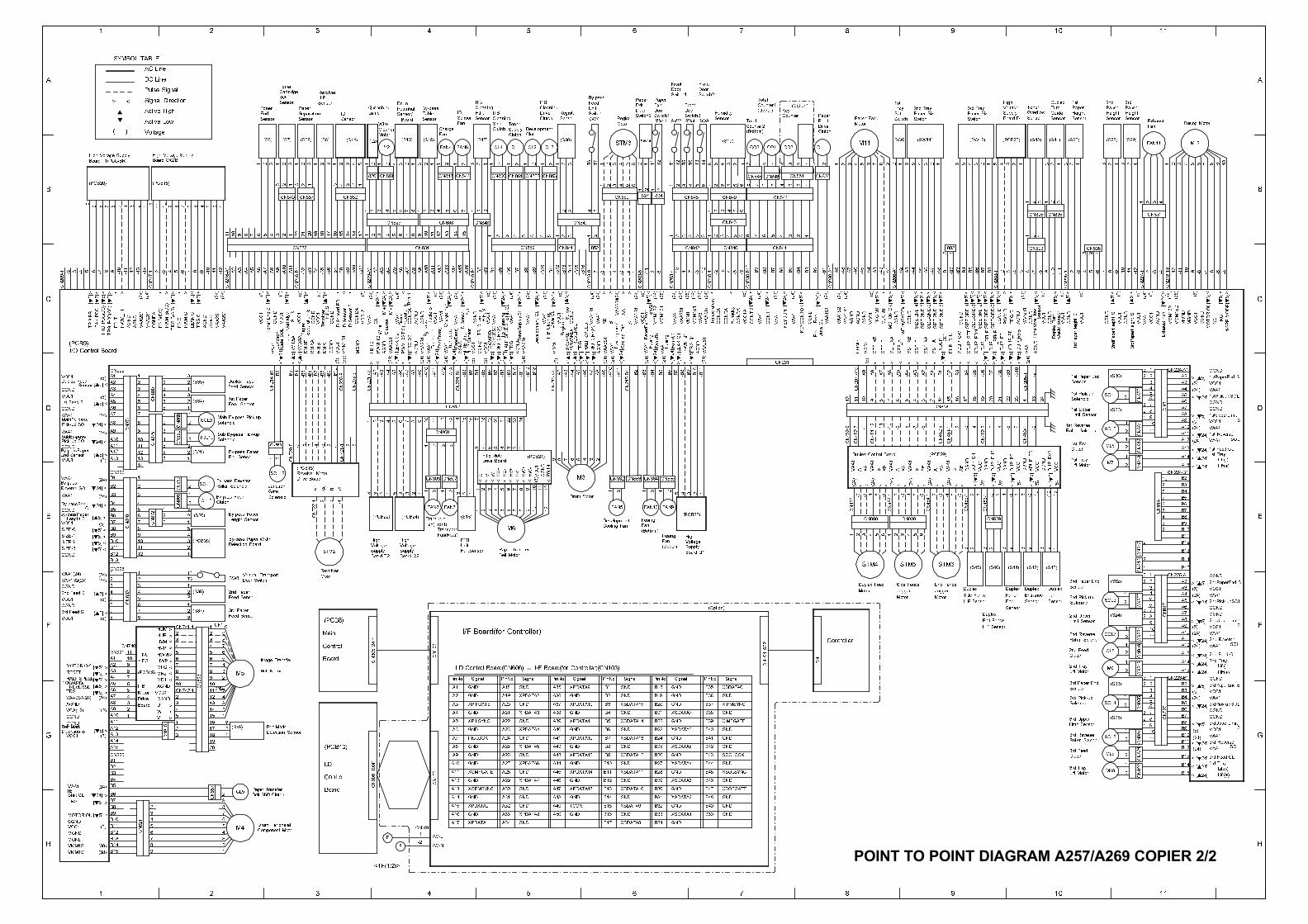
(S28)
Paper
Height
Paper
321 654 987 10
3
High
Sensor
Guide
Turn
Duplex
Board D
(PCB25) (S41)(S48)
Supply
Voltage
Sensor
Overflow
Toner3rd2nd
Sensor Sensor
Fan
Height
(S29)
21
3
3
1
4
CN808
1221
1
1
32
CN823
CN825
32
123
-7
VMM1S2
MGND
-5
CN835
23132
23
1
A4
A2
CN224
-B1
-8-9
VMM1S2
VCC1
CGND
1/2PP-M
ODE
-6
MGND
-4
MOTOROK
NC
TRG
CGND
A5
CN811
A11
11
A12 VAA1
CN224
VCC1
A8
A7
A15
A14
A13
-A1 CGND
CGND
A6
VAA1
A3 VCC1
A10 VAA1
A9
3rdPaperHeightS
2ndPaperHeightS
VCC1
VAA1
VCC1
-9-8-7
CGND
ExhaustFan
-4-6-5-4
VCC1
-2
CN227-1
AGND
CGND
-3-5 -3-2
CN225-1
GuideSensor
Sensor
VCC1
1stPaperHeightS
CGND
VAA2S1
DuplexTurn
CGND
VCC1
-9VCC1
AGND
-8-4-3
VAA1
DUP_RVS
XDUP_FD
DUP_PE
AGND
PWM
D
TRGD
TonerO
verflow
CGND
-7-6
CN855
7
1
2
1
CL6
SOL5Solenoid
5
2
1
SOL1
1
9
1
CN881
3
2
6
8
2
(S30)
3
4
2
23
24
22
CN480-1
13
1
11
1
CN813
1
2
CN812
3
2
10
(S22)
Paper Feed
SW9
Switch
-2-6-5
612 1
802
452323 4 156
Motor
(Upper)
Counter1
Key
Total
Feed
876543 92 5 4
SW4
Switch3
Switch2
Door
Front
(S15)
SW3Sensor
Door
Front (Option)
Counter
2
14
5 4
CN851
2 1 2
CN844
3
4 3 22 1
1
6
CN848
CN841
3
6 5
1
1
T4
T5
5
3
6
3 4 5 7
1 3
CN843
2 1
5 6
4
14 3
7
8
2
5 6
CN840
4
CN842
SIZE-2ND-0
6
3 4
1 322 4
8
CN849CN845
T3
T6
5 6
1
56 2
_SFHP
XDUP
CGND
LEAKD
_SET
SIZE-3RD-4
SIZE-3RD-2
XSF_XA
SIZE-3RD-3
XSF_A
CGND
1stTraySetSW
CGND
DUP_CLK
SIZE-3RD-1
SIZE-3RD-0
SIZE-2ND-1
CN208-1
_EFHP
-2
DUP
DUP
XDUP_PDN
XDUP_STT
XDUP_CW
SIZE-2ND-3
SIZE-2ND-2
TRGMT
VCC1
VAA1S2
SIZE-2ND-4
AGND
MOTOROK
XEF_A
XEF_XA
XEF_B
CLKMT
XEF_XB
CGND
AGND
CGND
XSF_B
XSF_XB
-2 -421
17
16
-6
19
15
2
-4-3
VCC1
-7
CN482-9
12
-8
45 3
CN482-8-5
14
18
-3
CN482-2
CN481-1
CN813
(PCB29)
20
-9-10
CN482-7 -11
CN481-12
-1
678
CONT1
VAA1S1
PaperFeed
VAA1
DriveCL
CGND
VAA1
KEYCONT
KEYCONTOK
910
11
VCC1A
-4
Temperature
CGNDA
VAA2S1
VAA1
VAA3S1
Humidity
CGNDA
CGNDA
CONT2
VMM1
-3
TRGQ1
AGND
PWM
Q1
VAA2S1
VAA1S2
B14
CN226-A1 CGND
10
4
B12
-1 -6-5
CN210-1-6-7 -2
VMM1S1
VAA3
6
B9
B5
B4
7
B7
B6
B2
B15
3
5
B10
B3
8
9
B13
-B1
B11
B8
2
1
VAA1
CGND
CGND
VAA1
VCC1
2
2
VAA1
B2
VCC1
B3
CGNDCN817
CN226
CN814
3
CN816
1
1
CN815
2
(S44)
-13
31
-11
-10
-9
12
-5-4
2
-12
123
(S43)(S42)
-8-6
3
SOL3
CN881
1
1
M9
CN819
(S33)
(S24)
CN818
2
2
CL8
COL7
DuplexDuplex
Sensor
1
1
2
3
1
2
1
2
B9
CGND
B5
B15
B14
B7CN820
B11
Duplex
Sensor
End
Paper
Sensor
Entrance Turn
B4 VAA1
VCC1
B6 CGND
B13
B10 VAA1
B8
B12 VAA11
1
CN821
1
SOL8
2
1
CL9
M10
2
2
CN822
2
CN881
(S25)
SOL4
23
CN485-1
12
CN484-1 -2
CN486-1 -3
3 1
STM6STM4(S45)
54 32132
CN890
4
Motor
Jogger
End Fence
5 6
CN483-1
CN488-1
1 6
(Option)
CN10496P
4
Voltage
High
(PCB23)
23 1
Board Q1
Supply
Duplex Feed
CN
MotorDuplex
GNDB19
B29
B28
XSDATA7
B18
Signal
B20
B27
GND XIPMSYNC
GND
XSDATA0
GND
XIMFGATE
GND
Signal
GND
GND
SOCLOCK
GND
XSOLSYNC
GND
GND
B33
GND
B31
XSOFGATE
GND
GND
GND
B25
B24
B23
GND
XSDATA3
GND
GND
XSDATA6
GND
PinNo
XSDATA4
GND
XSDATA5
B26
B22
B21
Sensor
Door
Exit
Paper
SW13Motor
Regist.Switch2
Door
Exit
Paper
XSDATA1
GNDB32
B34
B30
XSDATA2
6
CN850
Clutch
Drive
Cleaning
Development
Clutch
Regist.
ITB
(S38)
T2
T1
1
1
32
827
2
1
32 4 5
1 2
824
1
T1
CN840
3
8
CN841
12
1
654 T2
22
4
215
21
76
CN862
21
3
21
21
3 T7
T6
5
21
CN863
Sensor/
Drum
Motor
Cleaner
Wire
Lamp
(S13)
Quenching
Board
Cleaning
ITB
(S17)
ID
Fan
Sensor
ITB
Fan
Charge
Sensor
H.P.
Shift
2
15
14
CN843
132
24
2
2
23
CN848
3
2
5
CN833
11
13
CN844
1
1
CN860
6
61 12
1
7
1
2
CN861
2
1 2 31 2
CN829
2
7 11
3
4
12
85 4
2 1
3
A
-8
Fan(U)
Fusing
10
9
1
76
5
3 4
11 3
826
512
8
4
CN831
B
-6 -5
SW2
CN203-4
VAA2
VAA3S1
CoolingFan
LEAKQ1
VAA1
XA
VAA3S1
Fan(B)
Fusing
VAA1
-1
VCC1
Development
CN203-5
AGND
-2
VMM1S1
VMM1S2
PaperExitDoor
VAA1
-4 -3 -2
VAA3S1
XB
DriveCL
VAA2S1
REVERSE
FOWARD/
CN223-8
BREAKE
TRG
CGND
Registration
DevelopmentCL
VCC1
TonerSupplyCL
ITB
Cleaning
348
1
2 1
VAA1
VCC1
VAA1
Sensor
VAA1S1
-7
HALFSPEED
MOTOROK
VAA1
REVERSE
ITB
Cleaning
9
(PCB21)
567
FOWARD/
HALFSPEED
H.P
Sensor
MOTOROK
VAA1Fan
AGND
CGND
VCC1
VAA1
ChargeFan
Fan(Rear)
Transport
Wire
VAA1
Transport
VAA1
CGND
IDSensor
VCC1
H.P.S
Fan(Front)
VAA1
ITB
Cleaning
ShiftCL
VAA1
VCC1
CGND
PTBUnit
TRG
TRGQ2
VAA2S1
CGND
VCC1
VAA2S1
LEAKQ2
PWM
Q2(DC)
Table
S
QL
Cleaner
VCC1A
VAA1
CGNDA
By-pass
M+
7 2
CN812
4
/Board
AGND
VAA1
AGND
M-
Drum
PotentialS
FBT2
PWM
T2
AGND
56 3
1 2
48
3
Set
Cartridge
Paper
ID
Revolver
Toner
Sensor
H.P.
Separation
Sensor
(S6)(S7) (S39)
1 4
16
17
18
212 5
End
Sensor
20
21
23
CN857
32
2
32
14
2
15
19
32
CN857
22
1
1 3
CN849
1
13
34
789 5
1 3
3
2
310
11
1 1
4 3
6
2
1
4
10
6789 12
23 1 89 510
11
4
(PCB15)
67
RM0.8A
H.P.S
VCC1
CGND
VCC1
CGND
VCC1
VMM1S1
Revolver
RM
XB
VCC1
MGND
CGNDA
SeparationS
TonerCartridge
Gate
SOL
RM
XA
RMB
RMA
SetS
CGND
IDSensor1
IDSensor2
IDSensorLED
RM1.5A
-2-3-4
TonerEndS
-9
VCC1
VAA2S1
VAA2S1
AGND
AGND
VAA1
CGND
Paper
Solenoid
SOL9
SOL10
-7
CN720-8 -3
(PCB18)
-2
CN721-1-1-5-6
AGND
-8-6-5
CN217-1 -3-2
AGND
PWM
G
FBG
TRGB(AC)
Solenoid
1
1st Paper
End Sensor 2
-9-8-7-3-2
FB_T1
-7
FBB(DC)
CGNDA
PWM
B(DC)
-4
PWM_T1
LEAKC
VAA2S1
VAA2S1
-6-5-4
CN209-1
LEAKPCC
(PCB9)
TRG
PCC(AC)
TRG
PCC(DC)
TRGBR
CN875
6
5
4
CN890
CN869
8
7
CN868
14
VCC1
1st Feed S
CGNDSensor
3
2
1
13
12
CN871
11
10
9
VAA1
CGND
End Sensor
SubBy-passVAA1
VCC1Duplex Feed
VCC1
MainBy-pass
CGND
Pick-up SOL
Pick-up SOL
Cooling Fan
Development
5
CN862
12
8 2
CN864
FAN5 FAN10 FAN9
Fan
Fusing
1 21
CN863
Fan
1 211
10
9
10
12
8 9 11
Fan(Rear)
7
1
Transport
CN807
765
65
W
(S18)
3
2
123
12 2U
FAN7
23
Supply
(PCB22)
14
Board T2
Supply
4
1 43
4
V
(PCB8)
CN102
Voltage
23
2
51
High
1
High
GND
GND
GNDA46
GND
GND
B10
B6
B2
A42
B4
B3
XPDATA13
XPDATA9
PinNo
A38
A37
A36
B5XPDATA11
XPDATA10
Control
Main
CN30524P
Board
PinNo
A21
XOMFGATE
GND
XPIFGATE
GND
A26
B12
B11XPDATA14
A35
A43
XPDATA12
A45
A44
GND
PinNo
B1
Signal
B9
B8
B7A41
A40
A39
GND
XPILSYNC
GND
A25
GND
GNDA24
Signal
A23
A22
GND
GND
PICLOCK
GND
GND A18
GND A29
A28
A27
GND
GND
GND
A20
A19
A34
A33
GND
GND
GND
GND
XPDATA0
GND
XPDATA1
XOPMSYNC
A32
A31
A47
B16
B15
A50 GND
TCONT
B17
A49
A48 B14
B13XPDATA15
GND
A7
A6
A2
CN103
A12
A11
A4
A3
A8
A1
A10
A9
A5
A30 GNDBoard
AC-N
A17
-1
CN101
A14
A13
F
AC-L
A16
A15
-2
(PCB10)
Control
LD
CN722-1
STM2
/BB/AA
Motor
-4-3-2
CN1
2nd Paper
SW8
By-pass Feed
SOL11
CL10 Clutch
6
3rd Paper
2
3
8
7
11
M5
CN823
1
5
9
10CN2
10
4
CN872
CN861
CN870
VAA1S2(24)
VAA1
VCC1
VAA1(24)
SIZE-0
Reverse SOL
VAA1
SIZE-2
Length S
SIZE-3
By-pass
CL
CGND
CGND
SIZE-1
By-passFeed
FG
MR2
HWM
HVP
10
ITB
1
CN740
(PCB19)
HUM
3
2
HWP
MR1
AGND
2
1
3
NC
MOTOR OK
VCC1
9
7
8
HVM
HUP
MFG
5
11
6
19
FOWARD/HALF SPEED
RESET
3rd Feed S
VCC1
CGND
CGND
REVERSE
2nd Feed S
CN857
18
16
13
14
17
20
CL5
(S16)2
3
M4
1
15
12CGNDDrive
AGND
Shift CL
VAA1
2
3
CN815
4
V
Board
1W
U
CN821
CGND
VCC1
VAA2S1(24)
Detection SBelt Mark
CGND
VCA(12)
PTB
1st Feed CL
1st ReverseSOL
Lift(+)
Lift(-)
S
1st
Sensor
Height
Paper
(S26)
Fusing Motor
(5)
<
[t5]
(Bottom)
Humidity
Switch
Paper Size
2nd Tray
(SW11)
1st Upper
Roller
Sensor
Lift Motor
Solenoid
1st Tray
1st Reverse
Clutch
Limit Sensor
1st Pick-up
1st Feed
1st Paper End
1stPick-upSOL
1stPaperEnd S
1st Tray
1stUpperLimit
2ndUpperLimit
2ndPick-upSOL
2nd Feed CL
2nd Reverse
3rdPaperEnd S
Lift(+)
S
Lift(-)
2nd Tray
SOL
Duplex Control Board
CN846
Counter2
Total
3rdUpperLimit
3rdPick-upSOL
3rd Feed CL
3rd Reverse
Lift(+)
S
Lift(-)
3rd Tray
SOL
2nd Pick-up
Sensor
3rd Paper End
Sensor
Solenoid
2nd Tray
2nd Feed
Clutch
Roller Solenoid
2nd Reverse
Limit Sensor
Lift Motor
2nd Upper
2nd Paper End
B42
B40
B39
B38
Controller
Motor
Jogger
Side Fence
STM5
CN888
Roller Solenoid
3rd Reverse
Solenoid
3rd Feed
Limit Sensor
3rd Upper
3rd Pick-up
Clutch
3rd Tray
Lift Motor
B47
B50
B46
B45
B44
PinNo
B41
B37
B36
B35
B43
Potential
Sensor
Table
By-pass
(S19)
852
Switch
By-pass
Unit
Feed
SW7
B49
B48
Sub By-pass Pick-up
Main By-pass Pick-up
Feed Sensor
Junction
(PCB20)
5
Board T1/PCC/BR
High Voltage Supply
Toner
Sensor
(S8)
CN808
CN222
By-passPaper By-pass Paper
Feed Sensor
Duplex Paper
CN860
Fan(Front)
Transport
CN806
Board Q2
Voltage
(PCB24)
FAN8
Drum MotorGate
By-pass Paper
By-pass Reverse
Detection Board
By-pass Paper Width
Vertical Transport
JunctionRoller Solenoid
Length Sensor
Door Switch
<1F(1/2)>
F
XPDATA8
XPDATA7
XPDATA6
XPDATA4
Signal
XPDATA5
XPDATA3
XPDATA2
B11
B4
B5
B10
B3
CN228
Belt Motor
Feed Sensor
Feed Sensor
Solenoid
A5
A1
A3
B12
B2
B13
B1
By-passPaper B6
B9
B8
B7
A9
A8
A13
Belt Mark
Detection Sensor
A2
CN220
A6
A4
A10
A7
A14
A15
A12
A11
M12
(38)
(38)
M11CO2 CL11CO1 CO3
(S32)
CN855
2ndPaperEnd S
-B10
-B9
CN231
-B8
M2
SW14
CL3CL2STM3
-A2
-A6
-A5
CN215-A1
-B5
-B4
-A11
-B11
-A10
FAN4
(L2)
FAN6 CL4
-B6
-A7
-B13
-B12
-B7
-B6
-B2
CN215-B1
-B3
-A9
-A8
-A4
-A3
-A9
CN221-A1
-B2
CN221-B1
-B9
-A11
-A10
-A4
-B10
-B5
-B4
-A5
-B6
-B7
-B8
-B3
-A7
-A6
-A2
-B7
-A8
-A3
-B8
-A13
-B4
-B5
-B9
-B10
CN214-B1
-B2
-B3
Exhaust
CN831
FAN11
TRG [t5]
CN830
CN606100P
CN806
Drive
Paper
Clutch
Board C/G/B
High Voltage Supply
PTB Motor
Drive Board
TonerClutch
Clutch
CN861
Cleaning
CN859
Supply
CL1
M6
(S34)
I/O Control Board
TRGC
(S35)
(S21)
(S37)
PinNo
Belt Motor
Paper Transfer
(PCB28)
(S20)
T1
T2
(S36)
3
-10
-11
12
-12
-12
CN218-13
-10
-11
-10
-11
-A4
-A5
-B6
-B5
-B4
-B5
1
-B1
-B7
-A1
-A8
-A4
-A3
-A2
-B1
-B8
-B9
-A7
CN230-A10
CN230-B10
-A6
-A8
-A9
-B2
-A7
-A6
-A5
CN206-A1
-B4
-B6
-B3
VCC1
CN855
-A2
-A3
2
-B8
-B7
-B3
-B2
-12
-A13
-A12
-B4
-B2
-B3
-11
-10
-A14
-A10
-A9
CN219-B1
-B11
-B10
-A11
-B15
-B14
-A6
-B12
-B9
-A5
-A4
-B8
-A3
-A2
CN219-A1
-B7
-B6
-B11
-B5
-A15
-A8
-A7
-A16
-B16
-B13
-A2
-B6
-11
-A5
-A4
-B3
-B2
CN216-B1
-11
CN216-A1
-B10
-B9
-10
-A10
-A6
-B5
-B4
-A11
-14
-13
-12
-A9
-A8
-A7
-A3
-B8
-B7
-10
-12
3rd Tray
(SW12)
Paper Size
VCC1MotorTRG
(S14)
CN852
CN929
Duplex
(S46)
Side Fence
H.P.Sensor
H.P.Sensor
End Fence
VAA1
DUP_EHP
CGND
XB
CGND
VCC1
DUP_PE
Belt Shift Clutch
Paper Transfer
Drum Peripheral
Component Motor
Revolver
Drive Board
Image Transfer
Sensor
VAA1
XA
A BVAA1
XB
M7
CGND
VCC1
A VAA1
AVAA1
XB
CGND
VCC1
DUP_SHP
DUP_RVS
XA
XDUP_FD
CGND
VCC1
BVAA1
XA
B VCC1
HW+
HV-
HV+
M3CGND
VCC1
HW-
Revolver Motor HU-
HU+
FG-IN
CN865
SOL12
XSDATA8
GND
XSDATA9
GND
SW2
GND
XSDATA14
GND
Switch1
Door
GND
(Upper)
GND
XSDATA15
(Bottom)
CN865
GND
XSDATA11
XSDATA13
LD Control Board(CN606) ↔ I/F Board(for Controller)(CN103)
I/F Board(for Controller)
Signal
GND
GND
XSDATA12
Front
Switch1
Fusing
XSDATA10
4
5
6
7
8
3
1
2
9
1
2
1
9
6
5
4
3
2
8
7
B6
B1
B7
B5
CN220
B4
B3
B2
B12
B14
B13
B9
B11
B10
B15
B8
VMM1S1
CGND
MGND
VCC1
MOTOR OK
VMM1S1
MGND
<
[t24]
<
(24)
(5)
[t5] <
(12)
(24)
<
[t5]
<
[s5]
<
[t5]
<
[t5]
<
[t5]
<
9
6
2
5
4
3
8
1
7
5
3
2
1
4
<
<
<
<
<
<
>
>
>
<
<
<
7
2
10
6
3
4
5
8
9
4
3
1
2
3
2
5
CN742-1
CN741-1
1
2
8
7
3
6
5
4
2
1
5
8
7
6
4
3
(5)
[s5] <
(24)
(5)
(24)
[s5] <
11
5
7
6
3
12
1
8
2
10
9
4
3
2
1
4
5
1
2
1
1
2
2
2
1
3
3
2
1
5
4
6
7
2
1
6
5
4
3
3
2
1
2
3
1
2
1
2
2
3
1
3
1
A13
A4
A8
A12
A11
CN222
A7
A10
A5
A2
A1
A3
A9
A6
(5)
(24)
[s5] <
(5)
[s5] <
(5)
[s5] <
[t24] >
[t24] >
(24)
(5)
[s5] <
[t24] >
(24)
(24)
[t24] >
[t5] <
[t5] <
[t5] <
[t5] <
(24)
[s24]<
2
3
1
6
7
8
9
10
11
4
5
1
3
2
2
3
1
A2
A4
A12
A10
A11
A6
A9
A5
A14
A3
A13
A8
A7
A15
1
2
8
9
76
10
11
5
3
4
[s24]<
(24)
[t24]<
[t24]<
(5)
[t5]>
(24)
[t24]<
(5)
[s5]>
[s24]<
[s24]<
[t24]<
(24)
[t24]<
(24)
(5)
[t5]>
[t24]<
(24)
(5)
[s5]>
[t24]<
(24)
(5)
[s24]<
[s24]<
[t24]<
(24)
[t5]>
[t24]<
(5)
(24)
[s5]>
-5-4 -6-2 -3 -5-4 -6-2 -3 -5-4 -6-2 -3 -2 -3
(24)
<(24)
[t5]
>< (24)
< < (24)
< < < < (5) [t
5]
> (5)[t
5]
> (5) [t
5]
> (5)[t
5]
> (5)
(24)
< <(24)
< <
-B10
-2
CN205-1-B9
-A5
-B3
-B2
-B1
-A4
-B5
-A7
-A6
CN207-A10
-B7
-B6
-B8
-B4
-A1
-A2
-A3
-A8
-A9
-B11
PTB
H.P.Sensor
Unit
(5)
< < < < < < < < < <
24
22
18
17
16
12
21
20
13
11
7 10
23
19
15
14
1 62 98543
CN203-3
CN203-9
[t5]>
(24)
[t5]<
[t5]>
[t5]> < >
(24) < >
[t5]> < >
[t5]<
[t5]>
(24)
(24)
[t5]<
[t24]
< (5)[s5]
<
[s5]
< (38)
(24)
[t24]
<> < > < < (24)
(24)
(24)
-A12
[t24]
<
[t5]
[t5]
>[t
5]
(5)
(5)
<[t
5]
>[t
5]
<[t
5]
<[t
5]
(24)
<[s
5]
(5)
<[s
5]
<[t
5]
<[t
5]
>[t
5]
<[t
24]
(24)
(24)
(24)
(24)
(24)
<<[t
24]
<[t
24]
>[t
5]
<[t
5]
(5)
(24)
< >[t
5]
>[t
5]
>[t
5]
>[t
5]
>[t
5]
>[t
5]
< < < < < < < << < <
[t5]<
[s5]<
[s5]< < <
(24)
(5)
(5)
(5)
(5)
(5)
(24)
(5)
(24)
(24)
[t24]>
[t24]>
[t24]> <
[t5]<
[t24]>
[t24]>
[t5]<
[t24]>
[t24]>
[t24]>
[t24]>
[s5]<(5)
(5)
(24)
(24)
(24)
(24)
(24)
(24)
(38)
(38)
(5)
(24)> > > >
(24)
[t5]<
(24)
(24)
(24)
(24)
(38)
(38)
(5)< <
[t24]>
[t24]>
[t24]>
[t24]>
[t5]<
(24)
(24)
(24)
(24)
(24)
(24)
(5)
[t5]> >
[t5]<
[t5]<
[t5]<
[t5]<
[t5]<
[t5]<
[t5]<
[t5]<
[t5]<
[t5]<
[t5]<
[t5]<
[t5]<
[t5]>>
(24)
(5)
(5)
(5)
[t5]<
[t5]<
[s5]<
(24)
(38)
(38)
(5)
(5)
(5)
(5)
[s5]<
[s5]<
[t24]>
[t5]<
[t5]>
[t5]>
<
▼
)(
>
SYMBOL TABLE
▼
AC Line
DC Line
Signal Direction
Voltage
Pulse Signal
Active Low
Active High
1st
Set
Tray
Switch
POINT TO POINT DIAGRAM A257/A269 COPIER 2/2
3 4 5 6 7 8 9 10 11
B
C
D
E
F
G
H
1 2
B
C
D
E
F
G
H
A
B
C
D
E
F
G
H
A
>
3 4 5 6 7 8 9 10 111 2