service manual solid state color television
TRANSCRIPT
SERVICE MANUAL R/C: CLU-417UI
pNUSGI (Asawu4 cclAssos 1
CAUTION: Before servicing this chassis, it is important that the service technician read the “Safety Precautions” and “Product Safety Notices” in this Service Manual.
Ihis television receiver will display television 1
Closed Captioning (m or u ) in accordance with ParaaraDh 15.119 of the FCC rules.
TABLE OF CONTENTS SAFETY PRECAUTIONS .................................................... 2
PRODUCT SAFETY NOTICE.. ............................................ 3
POWER SOURCE.. ............................................................ .3
TECHNICAL SPECIFICATIONS .......................................... 4
TECHNICAL CAUTIONS ..................................................... 5
ADJUSTMENT SPECIFICATIONS ...................................... 6
WAVEFORMS AT EACH SECTION .................................. 26
TROUBLESHOOTING FLOWCHARTS.. ........................... 30
REPLACEMENT PARTS LIST ........................................... 33
NOTES ............................................................................ .50
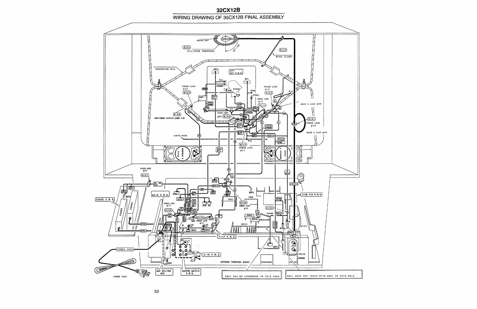
WIRING DRAWING OF 32CX12BKY62 FINAL ASSEMBLY ............................................................ 53
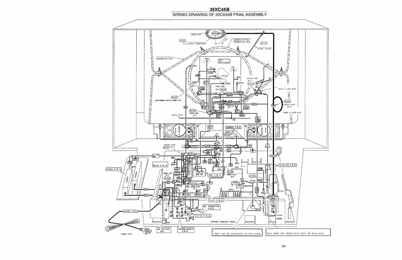
WIRING DRAWING OF 35CX45B/CZ67 FINAL ASSEMBLY ........................................................................ 54
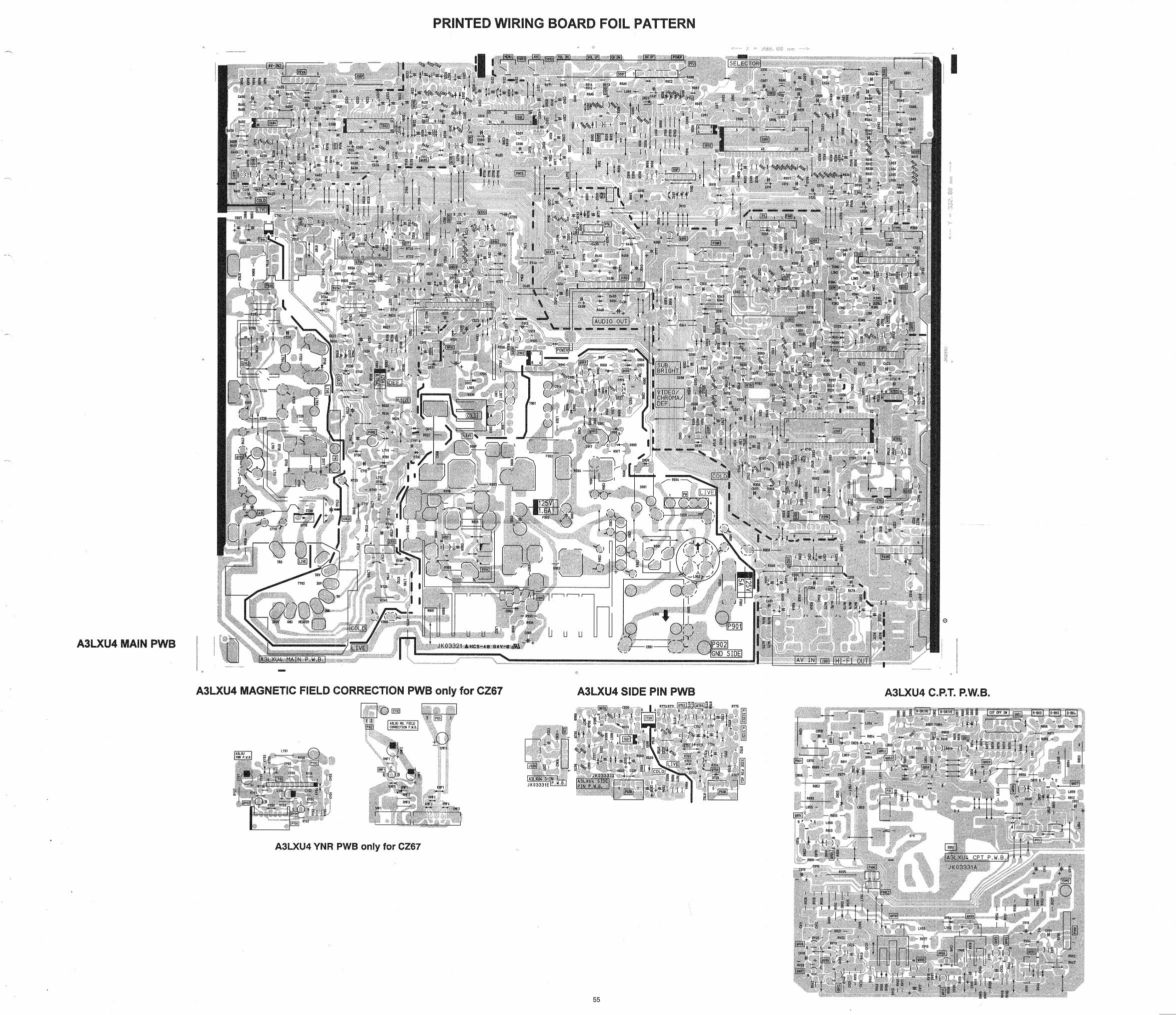
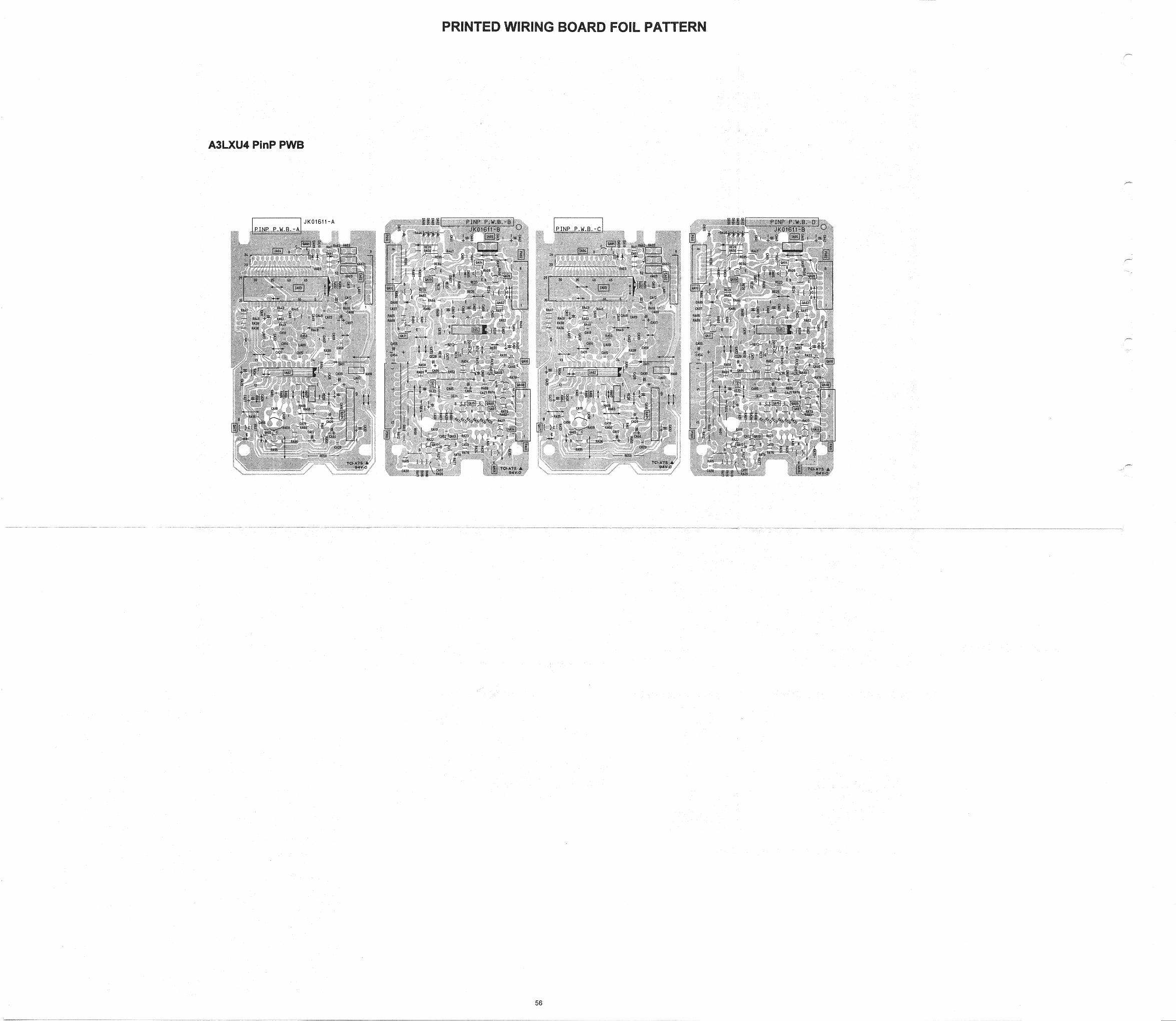
PRINTED WIRING BOARD FOIL PATTERN.. .................. 55
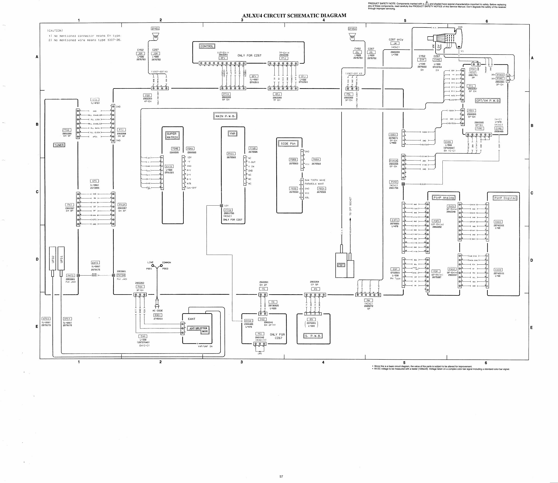
CIRCUIT SCHEMATIC DIAGRAM.. ................................... 57
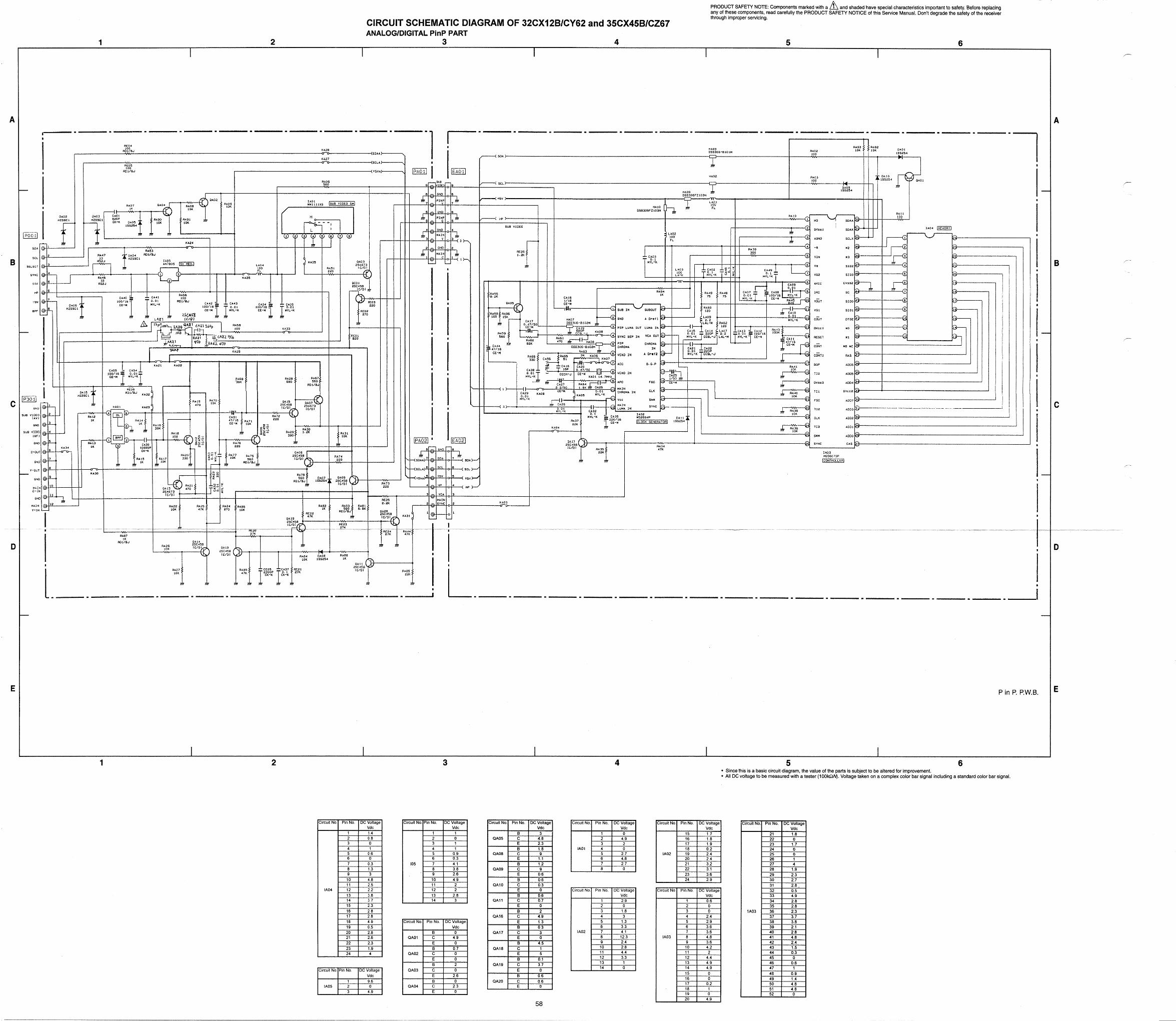
CIRCUIT SCHEMATIC DIAGRAM OF P in P.. .................. 58
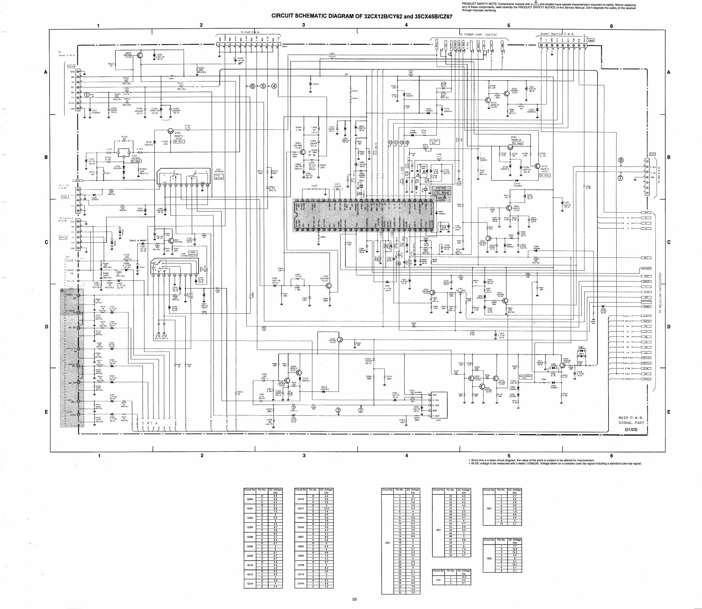
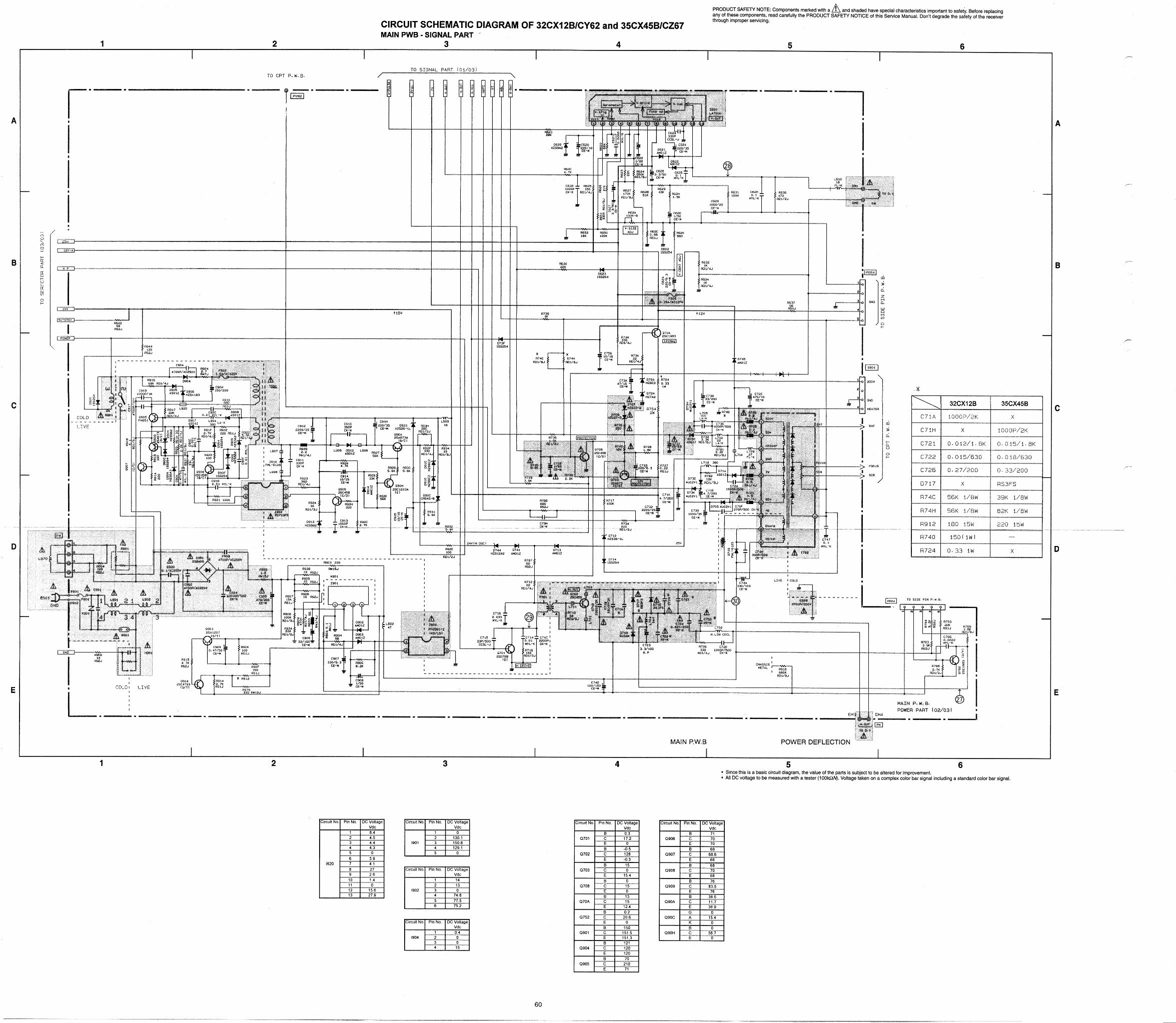
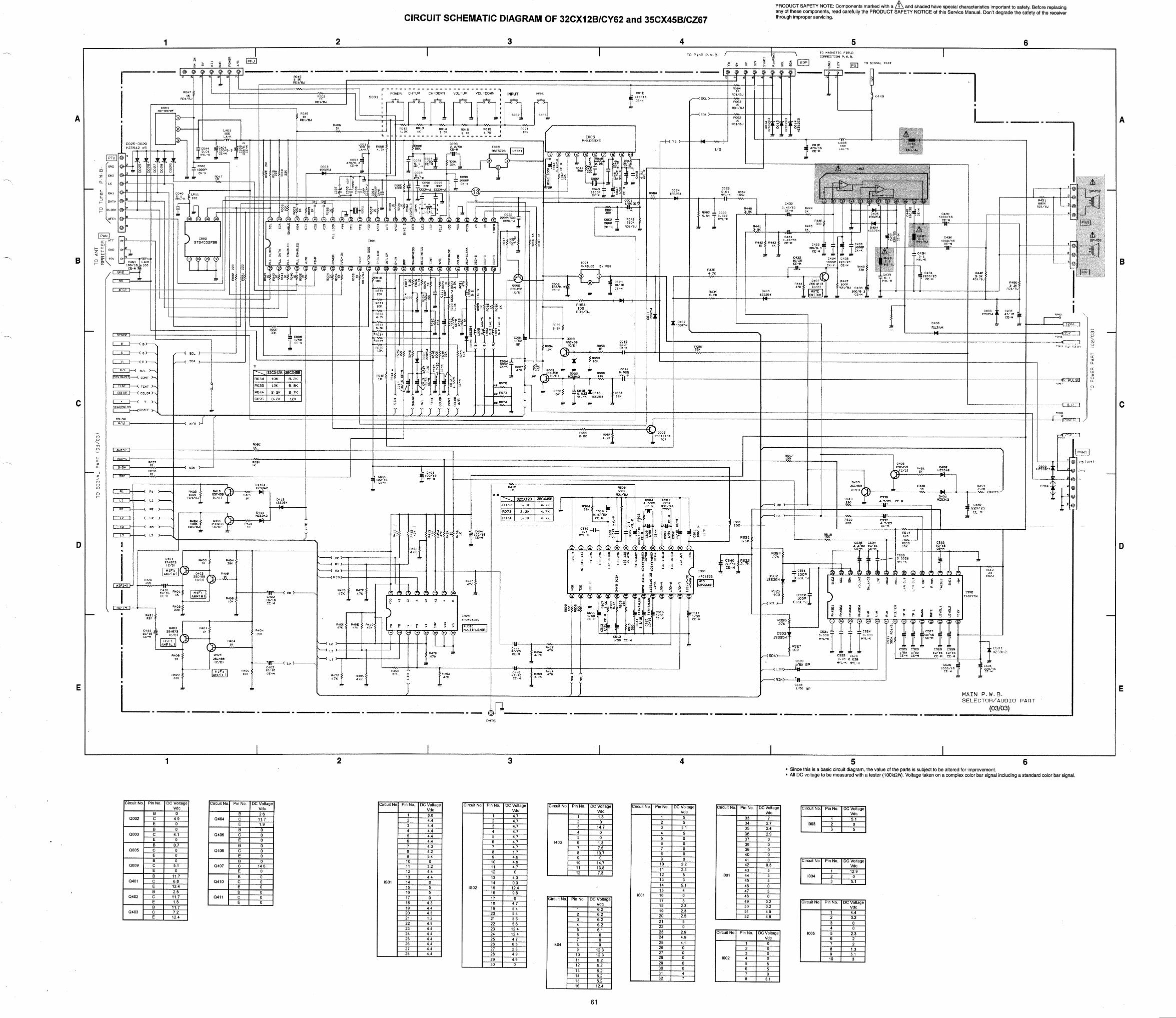
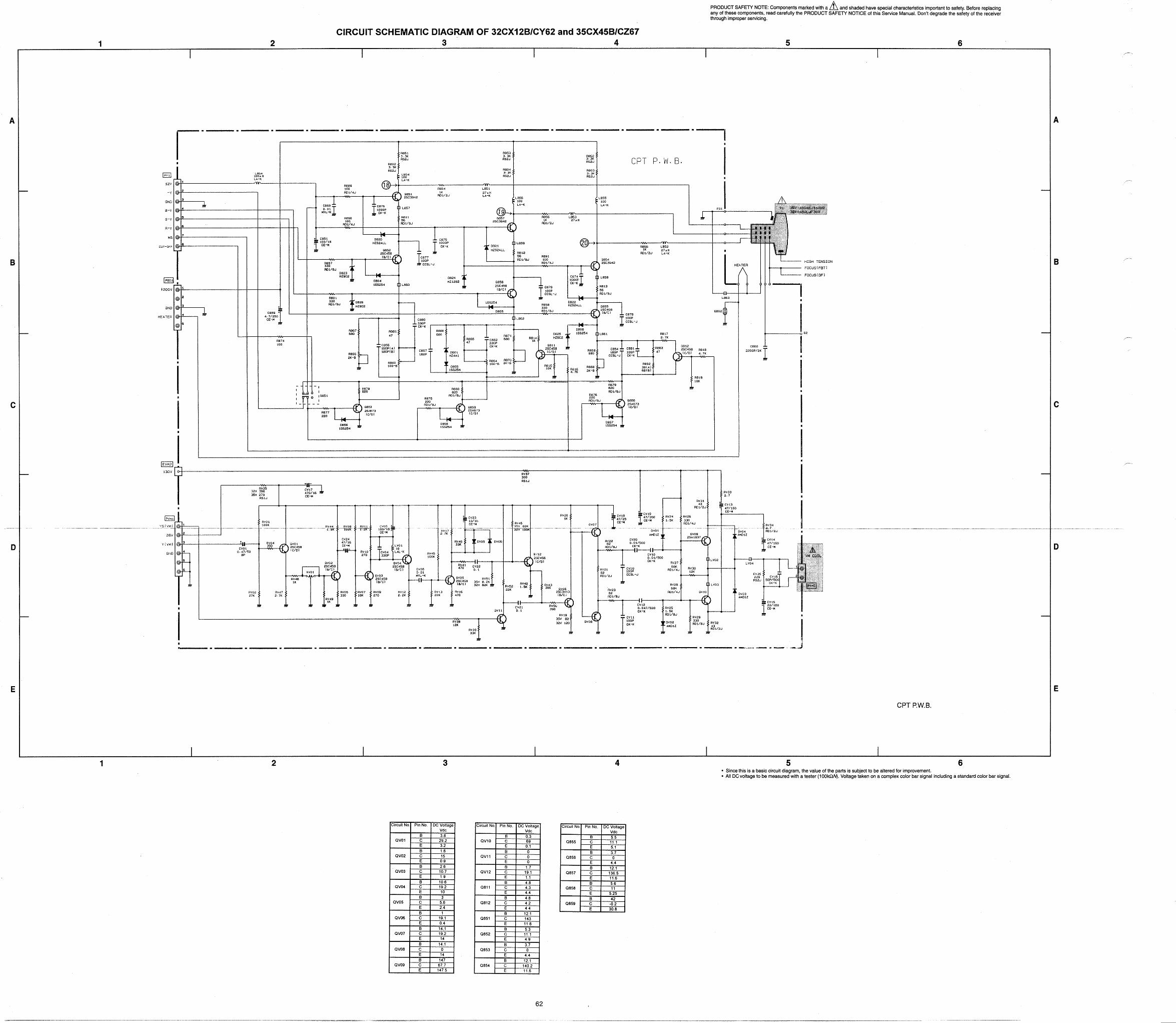
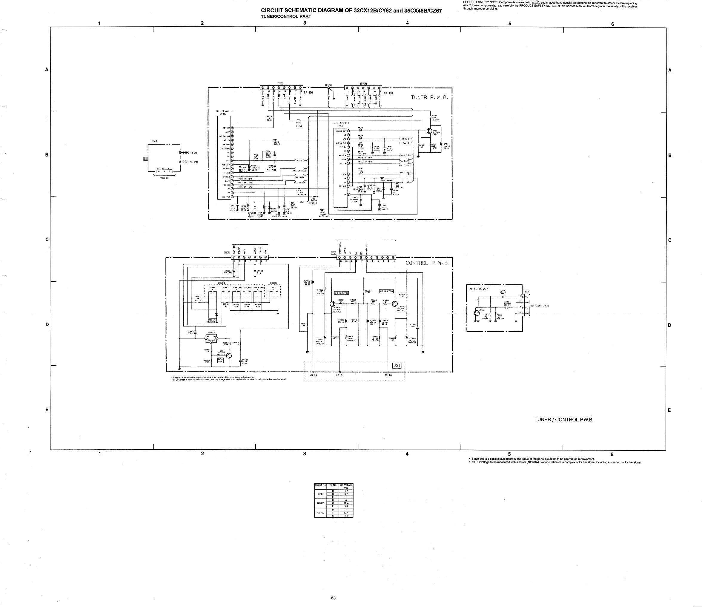
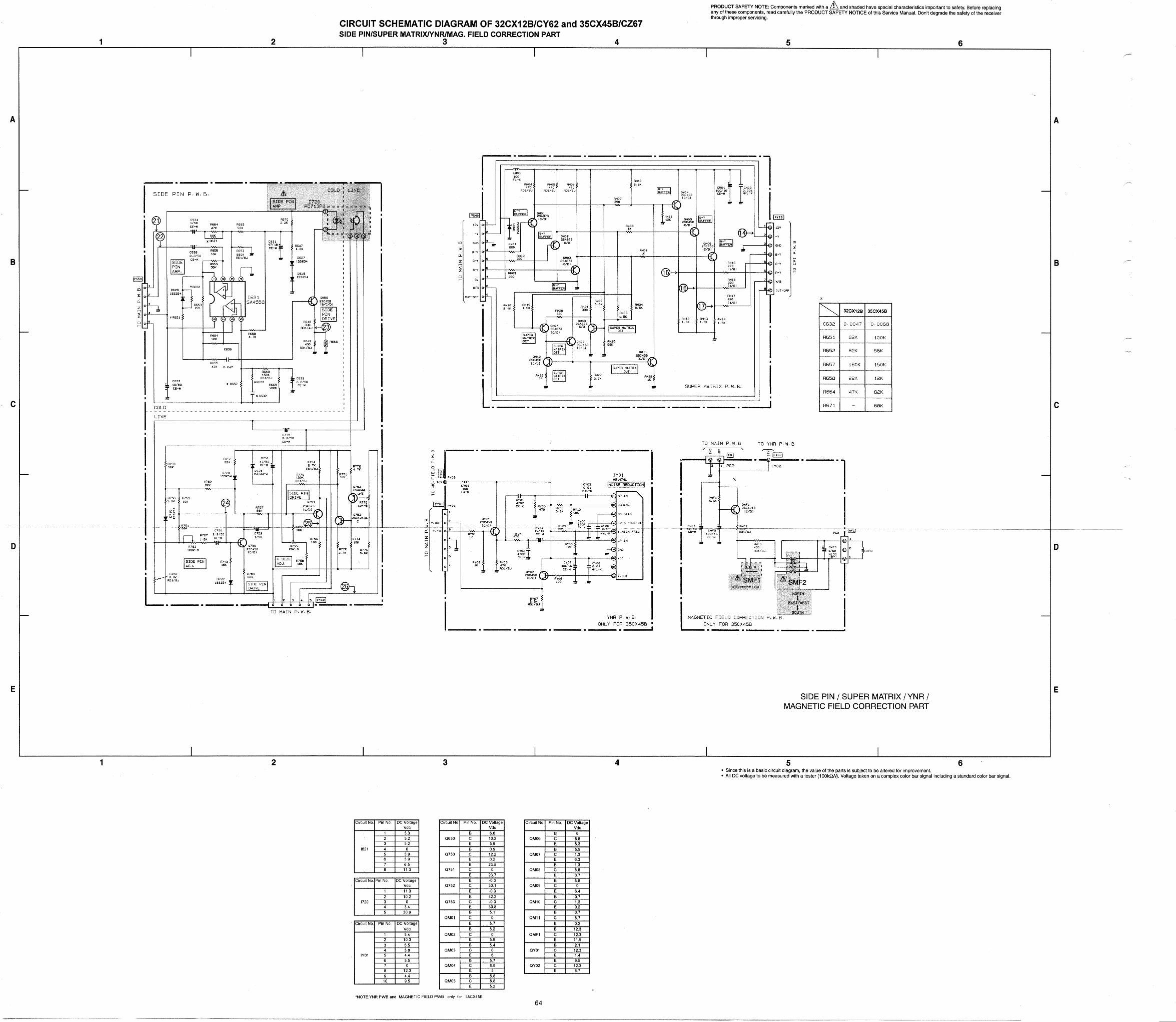
CIRCUIT SCHEMATIC DIAGRAM OF 32CX12B/CY62 and 35CX45BlCZ67 ........................................................... 59
SPECIFICATIONS AND PARTS ARE SUBJECT TO CHANGE FOR IMPROVEMENT
SOLID STATE COLOR TELEVISION DECEMBER 1996 HHEA- MANUFACTURING DIVISION
A3LXU4
SAFETY PRECAUTIONS
NOTICE: Comply with all cautions and safety related notes located on or inside the cabinet and on the chassis or pic- ture tube.
WARNING: Since the chassis of this receiver is connected to one side of theAC power supply during operation, when- ever the receiver is plugged in, service should not be at- tempted by anyone unfamiliar with the precautions neces- sary when working on this type of receiver:
The following precautions should be observed: 1. Do not install, remove, or handle the picture tube in any
manner unless shatterproof goggles are worn. People not so equipped should be kept away from the picture tube while handling.
2. When service is required, an isolation transformer should be inserted between power line and the receiver before any service is performed on a “HOT” chassis receiver
3. When replacing a chassis in the receiver; all the protec- tive devices must be put back in place, such as barriers, nonmetallic knobs, adjustment and compartment cover- shields, isolation resistors, capacitors, etc.
4. When service is required, observe the original lead dress in the high voltage circuitry area.
5. Always use the manufacturer’s replacement components. Critical components as indicated on the circuit diagram should not be replaced by another manufacturer’s. Fur- thermore, where a short circuit has occurred, replace those components that indicate evidence of overheat- ing.
6. Before returning a serviced receiver to the customer, the service technician must thoroughly test the unit to be certain that it is completely safe to operate without dan- ger of electrical shock, and be sure that no protective device built into the receiver by the manufacturer has become defective, or inadvertently defeated during ser- vicing.
Therefore, the following checks should be performed for the continued protection of the customer and service technician.
Leakage Current Cold Check With the AC plug removed from the 120VAC 60Hz source, place a jumper across the two plug prongs. Turn the AC power switch ON using an insulation tester (D&OOV), con- nect one lead to the jumperedAC plug and touch the other lead to each exposed metal part (antennas, screwheads, metal overlays, control shafts, etc.), particularly any exposed metal part having a return path to the chassis should have a minimum resistor reading of 0.24MD and a maximum resis- tor reading of 5.2MQ . Any resistance value below or above this range indicates an abnormality which requires correc- tive action. Exposed metal part not having a return path to the chassis will indicate an open circuit.
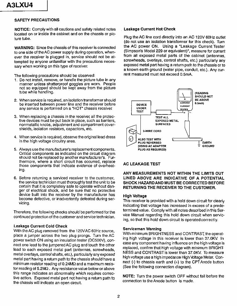
Leakage Current Hot Check
Plug the AC line cord directly into an AC 120V 60Hz outlet (do not use an isolation transformer for this check). Turn the AC power ON. Using a “Leakage Current Tester (Simpson’s Model 229 or equivalent)“, measure for current from all exposed metal parts of the cabinet (antennas, screwheads, overlays, control shafts, etc.) particularly any exposed metal part having a return path to the chassis or to a known earth ground (water pipe, conduit, etc.). Any cur- rent measured must not exceed OSmA.
I DEVICE UNDER
El 0 LEAKAGE
CURRENT
TEST I
\TESTER ~
‘+ -
TEST ALL EXPOSED METAL SURFACES
Z-WIRE CORD
‘I (READING SHOULD NOT BE ABOVE OSmA)
ALSO TEST WITH PLUG REVERSED (USING AC ADAPTER PLUG AS REQUIRED)
AC LEAKAGE TEST
ANY MEASUREMENTS NOT WITHIN THE LIMITS OUT LINED ABOVE ARE INDICATIVE OF A POTENTIAL SHOCK HAZARDAND MUST BE CORRECTED BEFORE RETURNING THE RECEIVER TO THE CUSTOMER.
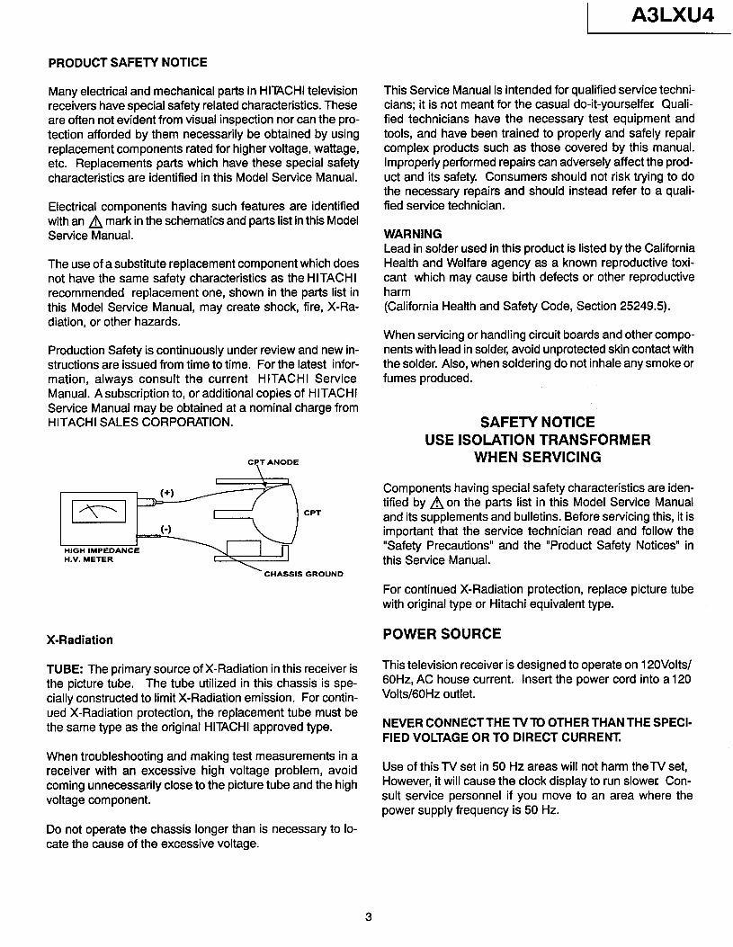
High Voltage This receiver is provided with a hold down circuit for clearly indicating that voltage has increased in excess of a prede- termined value. Comply with all notes described in this Ser- vice Manual regarding this hold down circuit when servic- ing, so that this hold down circuit is operated correctly.
Serviceman Warning With minimum BRIGHTNESS and CONTRAST, the operat- ing high voltage in this receiver is lower than 37.OKL! In case any component having influence on the high voltage is replaced, confirm that high voltage with minimum BRIGHT NESS and CONTRAST is lower than 37.OKV To measure high voltage use a high impedance High ultage Meter. Con- nect (-) to chassis earth and (t) to the CPTAnode button (See the following connection diagram).
NOTE: Turn the power switch OFF without fail before the connection to the Anode button is made.
2
A3LXU4
PRODUCT SAFETY NOTICE
Many electrical and mechanical parts in HITACHI television receivers have special safety related characteristics. These are often not evident from visual inspection nor can the pro- tection afforded by them necessarily be obtained by using replacement components rated for higher voltage, wattage, etc. Replacements parts which have these special safety characteristics are identified in this Model Service Manual.
Electrical components having such features are identified with an A mark in the schematics and parts list in this Model Service Manual.
The use of a substitute replacement component which does not have the same safety characteristics as the HITACHI recommended replacement one, shown in the parts list in this Model Service Manual, may create shock, fire, X-Ra- diation, or other hazards.
Production Safety is continuously under review and new in- structions are issued from time to time. For the latest infor- mation, always consult the current HITACHI Service Manual. Asubscription to, or additional copies of HITACHI Service Manual may be obtained at a nominal charge from HITACHI SALES CORPORATION.
CPT ANODE \
CPT
H.V. METER
‘CHASSIS GROUND
X-Radiation
TUBE: The primary source of X-Radiation in this receiver is the picture tube. The tube utilized in this chassis is spe- cially constructed to limit X-Radiation emission. For contin- ued X-Radiation protection, the replacement tube must be the same type as the original HITACHI approved type.
When troubleshooting and making test measurements in a receiver with an excessive high voltage problem, avoid coming unnecessarily close to the picture tube and the high voltage component.
This Service Manual is intended for qualified service techni- cians; it is not meant for the casual do-it-yourselfer Quali- fied technicians have the necessary test equipment and tools, and have been trained to properly and safely repair complex products such as those covered by this manual. Improperly performed repairs can adversely affect the prod- uct and its safety. Consumers should not risk trying to do the necessary repairs and should instead refer to a quali- fied service technician.
WARNING Lead in solder used in this product is listed by the California Health and Welfare agency as a known reproductive toxi- cant which may cause birth defects or other reproductive harm (California Health and Safety Code, Section 25249.5).
When servicing or handling circuit boards and other compo- nents with lead in solder, avoid unprotected skin contact with the solder. Also, when soldering do not inhale any smoke or fumes produced.
SAFETY NOTICE USE ISOLATION TRANSFORMER
WHEN SERVICING
Components having special safety characteristics are iden- tified by Aon the parts list in this Model Service Manual and its supplements and bulletins. Before servicing this, it is important that the service technician read and follow the “Safety Precautions” and the “Product Safety Notices” in this Service Manual.
For continued X-Radiation protection, replace picture tube with original type or Hitachi equivalent type.
POWER SOURCE
This television receiver is designed to operate on 120Voltsl 60Hz, AC house current. Insert the power cord into a 120 Volts/GOHz outlet.
NEVER CONNECTTHETVTO OTHERTHAN THE SPECI- FIED VOLTAGE OR TO DIRECT CURRENT.
Use of this TV set in 50 Hz areas will not harm then/ set, However, it will cause the clock display to run slower: Con- sult service personnel if you move to an area where the power supply frequency is 50 Hz.
Do not operate the chassis longer than is necessary to lo- cate the cause of the excessive voltage.
A3LXU4 I
TECHNICAL SPECIFICATIONS
POWER RATINGS
32CX12B/CY62 . . . . . . . . . . . ..*......................................... 190 watts 35CX45B/CZ67 . . . . . . . . . . . . . . . . . . . . . . . . . . . . . . . . . . . . . . . . . . . . . . . . . . . . . . . 205 watts
COLOR PICTURE TUBE
32CX12B/CY62 . . . . . . . . . . . . . . . . . . . . . . . . . . . . . . . . . . . . . . . . . . . . . . . . . . . A80LJF30X 35CX45B/CZ67 . . . . . . . . . . . . . . . . . ..a..............*............ A89AE J 15X02
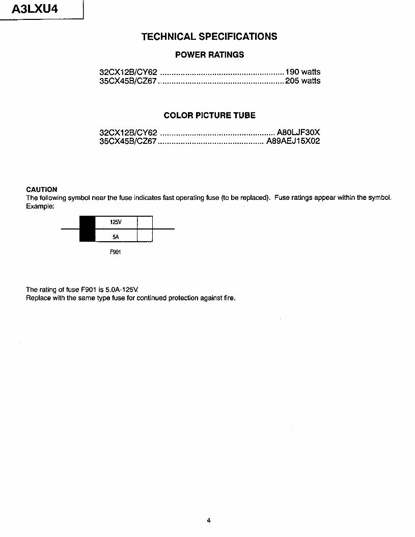
CAUTION The following symbol near the fuse indicates fast operating fuse (to be replaced). Fuse ratings appear within the symbol. Example:
The rating of fuse F901 is 5.OA-125V Replace with the same type fuse for continued protection against fire.
4
A3LXU4
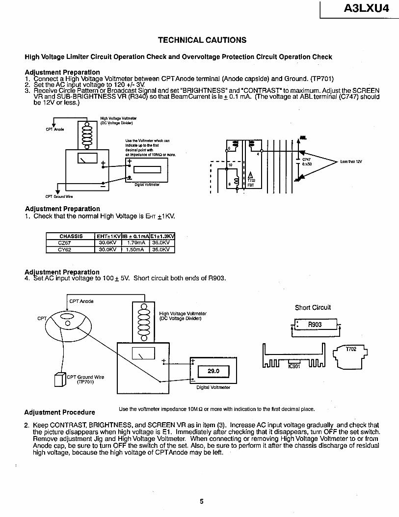
TECHNICAL CAUTIONS
High Voltage Limiter Circuit Operation Check and Overvoltage Protection Circuit Operation Check
Adjustment Preparation 1. Connect a High Voltage Voltmeter between CPTAnode terminal (Anode capside) and Ground. (TP701) 2. Set the AC input voltage to 120 +/- 3V 3. Receive Circle Pattern or Broadcast Si
VR and SUB-BRIGHTNESS VR (R34 8 nal and set “BRIGHTNESS” and “CONTRAST” to maximum. Adjust the SCREEN
be 12V or less.) so that BeamCurrent is la + 0.1 mA. (The voltage at ABL terminal (C747) should
CPT Anode
1 High Voltage Voitmster (DC I+ltage Divider)
Use the Voltmeter which can indicate up to the firsi decimal point wim 6
I\
an impedance of lOMs2 or more.
+ + m-w mm .
I
I 10 I
4 I
Digital Voltmeter I I
%.
6
I CPT Ground wire
Adjustment Preparation 1. Check that the normal High Mltage is EHT +l KV.
CHASSIS EHT=l KV IB 2 0.1 mA El +1.3d CZ67 3O.QW 1.70mA 36.OUV
CY62 3o.oKv 1.50mA 36.OKV
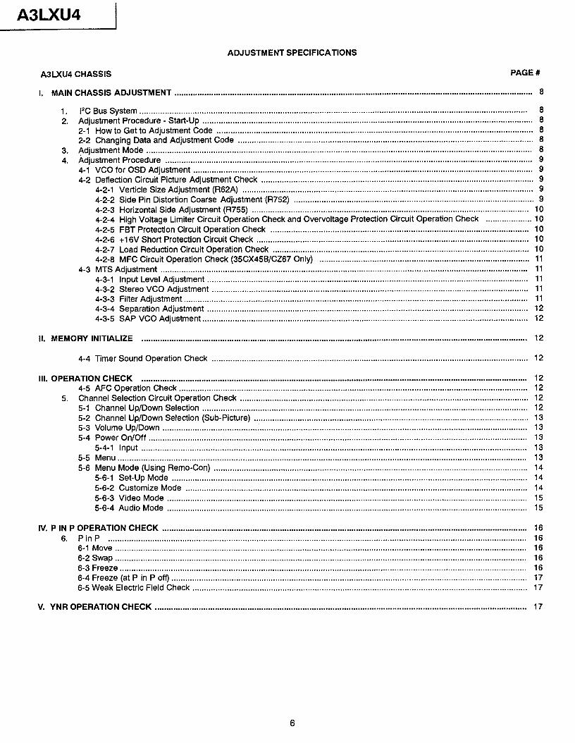
Ad’ustment Preparation 4. ki et AC input voltage to 100 + 5V. Short circuit both ends of R903.
I I I CPTAnode
CPT Ground Wire (TP701)
Adjustment Procedure
High Voltage Voltmeter (DC Voltage Divider)
Digital Voltmeter
Short Circuit
Use the voltmeter impedance 10M Q or more with indication to the first decimal place.
2. Keep CONTRAST, BRIGHTNESS, and SCREEN VR as in item (3). increase AC input voltage gradually and check that the picture disappears when high voltage is El. Immediately after checking that it disappears, turn OFF the set switch. Remove adjustment Jig and High Voltage Voltmeter. When connecting or removing High Voltage Voltmeter to or from Anode cap, be sure to turn OFF the switch of the set. Also, be sure to perform it after the chassis discharge of residual high voltage, because the high voltage of CPTAnode may be left.
5
A3LXU4
ADJUSTMENT SPECIFICATIONS
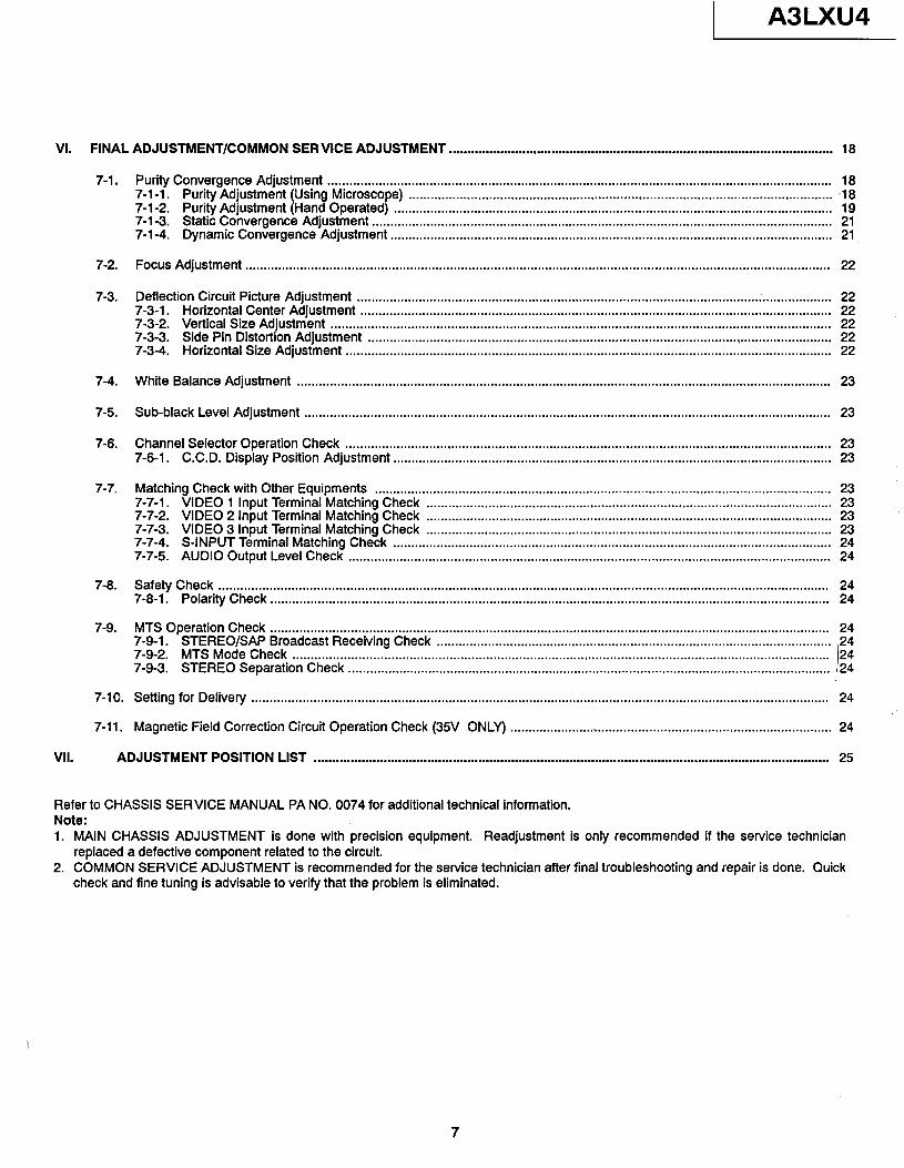
A3LXU4 CHASSIS PAGE #
I. MAIN CHASSIS ADJUSTMENT ........................................................................................................................................................... 8
1. 1% Bus System ........................................................................................................................................................................ 8 2. Adjustment Procedure - Start-Up ............................................................................................................................................... 8
2-l How to Get to Adjustment Code ......................................................................................................................................... 8 2-2 Changing Data and Adjustment Code ................................................................................................................................ 8
3. Adjustment Mode ....................................................................................................................................................................... 8 4. Adjustment Procedure ............................................................................................................................................................... 9
4-1 VCO for OSD Adjustment ................................................................................................................................................... 9 4-2 Deflection Circuit Picture Adjustment Check ...................................................................................................................... 9
4-2-l Verticle Size Adjustment (R62A) .............................................................................................................................. 9 4-2-2 Side Pin Distortion Coarse Adjustment (R752) ........................................................................................................ 9 4-2-3 Horizontal Side Adjustment (R755) ........................................................................................................................ 10 4-2-4 High Voltage Limiter Circuit Operation Check and Overvoltage Protection Circuit Operation Check .................... 10 4-2-5 FBT Protection Circuit Operation Check ................................................................................................................ 10 4-2-6 +16V Short Protection Circuit Check ...................................................................................................................... 10 4-2-7 Load Reduction Circuit Operation Check ............................................................................................................... 10 4-2-8 MFC Circuit Operation Check (35CX45BKZ67 Only) ........................................................................................... 11
4-3 MTS Adjustment ............................................................................................................................................................... 11 4-3-l Input Level Adjustment ........................................................................................................................................... 11 4-3-2 Stereo VCO Adjustment ......................................................................................................................................... 11 4-3-3 Filter Adjustment ..................................................................................................................................................... 11 4-3-4 Separation Adjustment ........................................................................................................................................... 12 4-3-5 SAP VCO Adjustment ............................................................................................................................................. 12
II. MEMORY INITIALIZE . . . . . . . . . . . . . . . . . . . . . . . . . . . . . . . . . . . . . . . . . . . . . . . . . . . . . . . . . . . . . . . . . . . . . . . . . . . . . . . . . . . . . . . . . . . . . . . . . . . . . . . . . . . . . . . . . . . . . . . . .......*....................................... 12
4-4 Timer Sound Operation Check . . . . . . . . . . . . . . . . . . . . . . . . . . . . . . . . . . . . . . . . . . . . . . . . . . . . . . . . . . . . . . . . . . . . . . . . . . . . . . . . . . . . . . . . . . . . . . . . . . . . . . . . . . . . . . . . . . . . . . . . ................. 12
Ill. OPERATION CHECK ....................................................................................................................................................................... 12 4-5 AFC Operation Check ....................................................................................................................................................... 12
5. Channel Selection Circuit Operation Check ............................................................................................................................. 12 5-l Channel Up/Down Selection ............................................................................................................................................. 12 5-2 Channel Up/Down Selection (Sub-Picture) ....................................................................................................................... 13 5-3 Volume Up/Down .............................................................................................................................................................. 13 5-4 Power On/Off .................................................................................................................................................................... 13
5-4-l Input ....................................................................................................................................................................... 13 5-5 Menu ................................................................................................................................................................................. 13 5-6 Menu Mode (Using Remo-Con) ........................................................................................................................................ 14
5-6-l Set-Up Mode .......................................................................................................................................................... 14 5-6-2 Customize Mode .................................................................................................................................................... 14 5-6-3 Video Mode ............................................................................................................................................................ 15 5-6-4 Audio Mode ............................................................................................................................................................ 15
IV. P IN P OPERATION CHECK .............................................................................................................................................................. 16 6. PinP ..................................................................................................................................................................................... 16
6-1 Move .................................................................................................................................................................................. 16 6-2 Swap .................................................................................................................................................................................. 16 6-3 Freeze ................................................................................................................................................................................ 16 6-4 Freeze (at P in P off) .......................................................................................................................................................... 17 6-5 Weak Electric Field Check ................................................................................................................................................. 17
V. YNR OPERATION CHECK . . . . . . . . . . . . . . . . . . . . . . . . . . . . . . . . . . . . . . . . . . . . . . . . . . . . . . . . . . . . . . . . . . . . . . . . . . . . . . . . . . . . . . . . . . . . . . . . . . . . . . . . . . . . . . . . . . . . . . . . ......................................... 17
6
A3LXU4
VI. FINAL ADJUSTMENT/COMMON SERVICE ADJUSTMENT . . . . . . . . . . . . . . . . . . . . . . ..*................................................................................ 18
7-1. Purity Convergence Adjustment .......................................................................................................................................... 18 7-1-1. Purity Adjustment (Using Microscope) .................................................................................................................... -18 7-l-2. Purity Adjustment
Static (Hand
Convergence Operated) ........................................................................................................................ 19
7-1-3. Adjustment .............................................................................................................................. 21 7-l-4. Dynamic Convergence Adjustment ......................................................................................................................... 21
7-2.
7-3.
Focus Adjustment . . . . . . . . . . . . . . . . . . . . . . . . . . . . . . . . . . . . . . . . . . . . . . . . . . . . . . . . . . . . . . . . . . . . . . . . . . . . . . . . . . . . . . . . . . . . . . . . . . . . . . . . . . . . . . . . . . . . . . . . ........................................ 22
Deflection Circuit Picture Adjustment .................................................................................................................................. 22 7-3-l. Horizontal Center Adjustment ................................................................................................................................. 22 7-3-2. Vertical Size Adjustment ......................................................................................................................................... 22 7-3-3. Side Pin Distortion Adjustment ..................................................................................................... . ......................... 22 7-3-4. Horizontal Size Adjustment ..................................................................................................................................... 22
7-4.
7-5.
7-6.
White Balance Adjustment .................................................................................................................................................. 23
Sub-black Level Adjustment . . . . . . . . . . . . . . . . . . . . . . . . . . . . . . . . . . . . . . . . . . . . . . . . . . . . . . . . . . . . . . . . . . . . . . . . . . . . . . . . . . . . . . . . . . . . . . . . . . . . . . . . . . . . . . . . . . . . . . . . ........................ 23
Channel Selector Operation Check ..................................................................................................................................... 23 7-6-l. C.C.D. Display Position Adjustment ........................................................................................................................ 23
7-7.
7-8.
Matching Check with Other Equipments ............................................................................................................................. 23 7-7-l. VIDEO 1 input Terminal Matching Check ............................................................................................................... 23 7-7-2. VIDEO 2 Input Terminal Matching Check ............................................................................................................... 23 7-7-3. VIDEO 3 Input Terminal Check ............................................................................................................... 23 7-7-4. S-INPUT Terminal
Matching Matching Check ........................................................................................................................ 24
7-7-5. AUDIO Output Level Check .................................................................................................................................... 24
Safety Check ....................................................................................................................................................................... 24 7-8-l. Polarity Check ......................................................................................................................................................... 24
7-9. MTS Operation Check ......................................................................................................................................................... 24 7-Q-l. STEREO/SAP Broadcast Receiving Check ............................................................................................................ 24 7-Q-2. MTS Mode Check ................................................................................................................................................... 24 7-Q-3. STEREO Separation Check .................................................................................................................................... 24
7-10. Setting for Delivery .............................................................................................................................................................. 24
7-11. Magnetic Field Correction Circuit Operation Check (35V ONLY) ........................................................................................ 24
VII. ADJUSTMENT POSITION LIST . . . . . . . . . . . . . . . . . . . . . . . . . . . . . . . . . . . . . . . . . . . . . . . . . . . . . . . . . . . . . . . . . . . . . . . . . . . . . . . . . . . . . . . . . . . . . . . . . . . . . . . . . . . . . . . . . . . . . . . . ..................... 25
Refer to CHASSIS SERVICE MANUAL PA NO. 0074 for additional technical information. Note: 1. MAIN CHASSIS ADJUSTMENT is done with precision equipment. Readjustment is only recommended if the service technician
replaced a defective component related to the circuit. 2. COMMON SERVICE ADJUSTMENT is recommended for the service technician after final troubleshooting and repair is done. Quick
check and fine tuning is advisable to verify that the problem is eliminated.
7
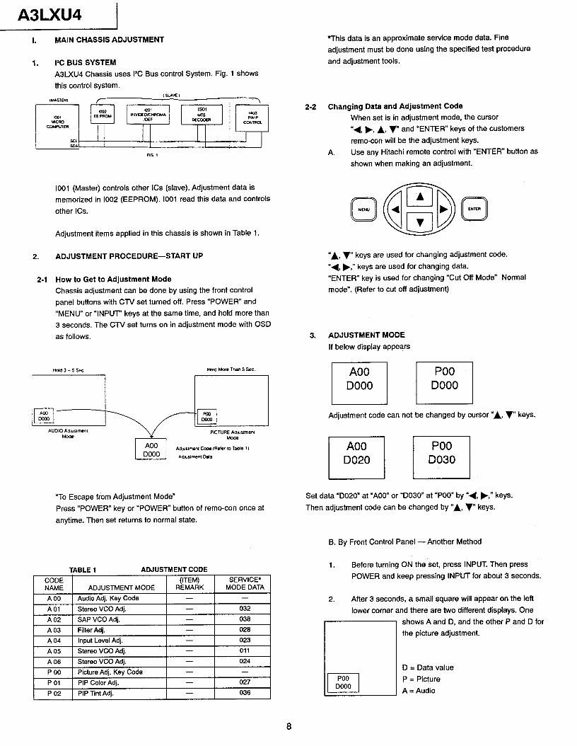
A3LXU4 I. MAIN CHASSIS ADJUSTMENT
1. I’C BUS SYSTEM
A3lXU4 Chassis uses 1% Bus control System. Fig. 1 shows
this control system. ~SLAVEI IMASTE6? r I
1001 (Master) controls other ICs (slave). Adjustment data is
memorized in 1002 (EEPROM). IO01 read this data and controls
other ICs.
Adjustment items applied in this chassis is shown in Table 1.
2. ADJUSTMENT PROCEDURE-START UP
2-1 How to Get to Adjustment Mode Chassis adjustment can be done by using the front control
panel buttons with CTV set turned off. Press “POWER” and
“MENU” or “INPUT” keys at the same time, and hold more than
3 seconds. The CTV set turns on in adjustment mode with OSD
as follows.
“To Escape from Adjustment Mode”
Press “POWER” key or “POWER” button of remo-con once at
anytime. Then set returns to normal state.
TABLE 1 ADJUSTMENT CODE
A04 Input Level Adj. - 023
A05 Stereo VCO Adj. - 011
A06 Stereo VCO Adi. - 024
P 00 Picture Adj. Key Code - -
P 01 PIP Color Adj. - 027
P 02 PIP Tint Adj. - 036
*This data is an approximate service mode data. Fine
adjustment must be done using the specified test procedure
and adjustment tools.
2-2 Changing Data and Adjustment Code
When set is in adjustment mode, the cursor
“4, p, A, v and “ENTER” keys of the customers
remo-con will be the adjustment keys.
A. Use any Hitachi remote control with “ENTER” button as
shown when making an adjustment.
0 ENTER
“A, v keys are used for changing adjustment code.
“4, b,” keys are used for changing data.
“ENTER” key is used for changing “Cut Off Mode” Normal
mode”. (Refer to cut off adjustment)
3. ADJUSTMENT MODE
If below display appears
Adjustment code can not be changed by cursor “A, v keys.
I I I I
Set data “D020” at “AOO” or “D030” at “POO” by “4, b,” keys.
Then adjustment code can be changed by “A, v keys.
B. By Front Control Panel -Another Method
1. Before turning ON the set, press INPUT. Then press
POWER and keep pressing INPUT for about 3 seconds.
Afler 3 seconds, a small square will appear on the left
lower corner and there are two different displays. One
shows A and D, and the other P and D for
the picture adjustment.
D = Data value
P = Picture
A = Audio
8
1 A3LXU4
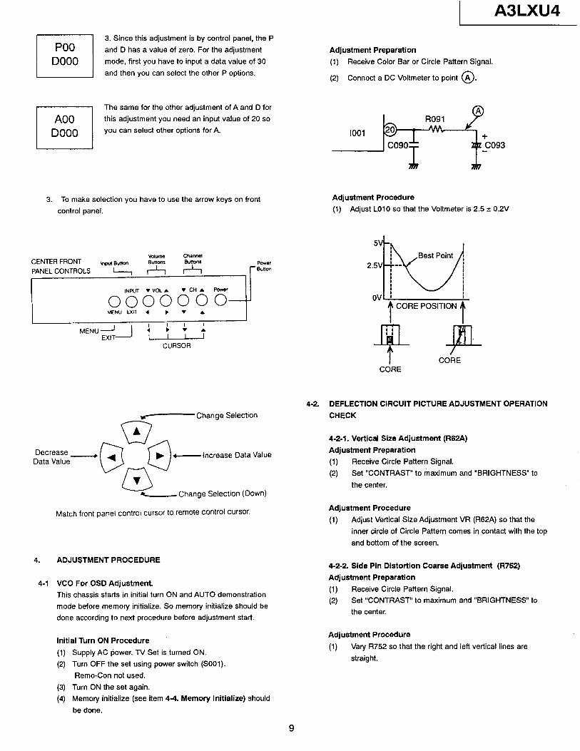
3. Since this adjustment is by control panel, the P
and D has a value of zero. For the adjustment
mode, first you have to input a data value of 30
and then you can select the other P options.
rl The same for the other adjustment of A and D for
A00 this adjustment you need an input value of 20 so
DO00 you can select other options for A.
I I
3. To make selection you have to use the arrow keys on front Adjustment Procedure
control panel. (1) Adjust LO10 so that the Voltmeter is 2.5 t 0.2V
CENTER FRONT PANEL CONTROLS ,
INWT . VOL. VCHA Power
0000000 MENU EXIT 4 l v .
I
MENU i \ t $
CURSOR
rr- Change Selection
Decrease l
Data Value c--Increase Data Value
-Change Selection (Down)
Match front panel control cursor to remote control cursor.
4. ADJUSTMENT PROCEDURE
4-1 VCO For OSD Adjustment, This chassis starts in initial turn ON and AUTO demonstration
mode before memory initialize. So memory initialize should be done according to next procedure before adjustment start.
Initial Turn ON Procedure
(1) Supply AC power. TV Set is turned ON.
(2) Turn OFF the set using power switch (SOOl).
Remo-Con not used.
(3) Turn ON the set again.
(4) Memory initialize (see item 4-4. Memory Initialize) should
be done.
Adjustment Preparation
(1) Receive Color Bar or Circle Pattern Signal.
(2) Connect a DC Voltmeter to point @.
ovl 1
t CORE POSITION
f
I CORE CORE
4-2. DEFLECTION CIRCUIT PICTURE ADJUSTMENT OPERATION
CHECK
4-2-l. Vertical Size Adjustment (R62A)
Adjustment Preparation
(1) Receive Circle Pattern Signal.
G-9 Set “CONTRAST” to maximum and “BRIGHTNESS” to
the center.
Adjustment Procedure
(1) Adjust Vertical Size Adjustment VR (R62A) so that the
inner circle of Circle Pattern comes in contact with the top
and bottom of the screen.
4-2-2. Side Pin Distortion Coarse Adjustment (R752)
Adjustment Preparation
(1) Receive Circle Pattern Signal.
(2) Set “CONTRAST” to maximum and “BRIGHTNESS” to
the center.
Adjustment Procedure
(1) Vary R752 so that the right and left vertical lines are
straight.
9
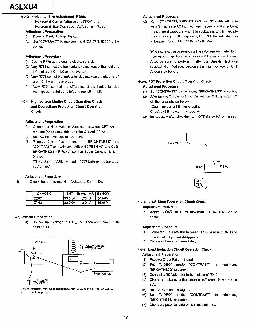
A3LXU4 4-2-3. Horizontal Size Adjustment (R755),
Horizontal Center Adjustment (R704) and
Horizontal Size Correction Adjustment (R775)
Adjustment Preparation
(1) Receive Circle Pattern Signal.
(2) Set “CONTRAST” to maximum and “BRIGHTNESS” to the
center.
Adjustment Procedure
(1) Set the R775 at the counterclockwise end.
(2) Vary R755 so that the horizontal size markers at the right and
left end are 1 .O - 1 .O on the average.
(3) Vary R775 so that the horizontal size markers at right and left
are 1.5 -1.5 on the average.
(4) Vary R704 so that the difference of the horizontal size
markers at the right and left end are within 1.5.
4-2-4. High Voltage Limiter Circuit Operation Check
and Overvoltage Protection Circuit Operation
Check
Adjustment Preparation
(1) Connect a High Voltage Voltmeter between CPT Anode
terminal (Anode cap side) and the Ground (TP701).
(2) Set AC input voltage to 120 + 3V.
(3) Receive Circle Pattern and set “BRIGHTNESS” and
“CONTRAST to maximum. Adjust SCREEN VR and SUB-
BRIGHTNESS VR(R340) so that Beam Current is Is +
0.1 mA.
(The voltage of ABL terminal - C747 both ends should be
12V or less)
Adjustment Procedure
(1) Check that the normal High Voltage is EHT + 1 KV.
CHASSIS EHT lBtO.1 mA El (KV)
CZ67 3o.oKV 1.70mA 36.OKV CY62 3o.oKV 1.50mA 36.OKV
Adjustment Preparation
4) Set AC input voltage to 100 + 5V. Then short-circuit both
ends of R903.
CPT
Hi h Volta e Voltmeter (08 Voltaje Dlvlder)
Digital Voltmeter
CPT Ground Wire (TP701)
Use a Voltmeter wrth input Impedance 10M ohm or more with indication to the 1 st decimal place.
Adjustment Procedure
(2) Keep CONTRAST, BRIGHTNESS, and SCREEN VR as in
item (3). Increase AC input voltage gradually, and check that
the picture disappears when high voltage is El. lmmediatly after checking that it disappears, turn OFF the set. Remove
adjustment jig and High Voltage Voltmeter.
When connecting or removing High Voltage Voltmeter to or
from Anode cap, be sure to turn OFF the switch of the set.
Also, be sure to perform it after the chassis discharge
residual High Voltage, because the high voltage of CPT
Anode may be left.
4-2-5. FBT Protection Circuit Operation Check
Adjustment Procedure
(1) Set “CONTRASJ” to maximum, “BRIGHTNESS” to center.
(2) After turning ON the switch of the set, turn ON the switch (S)
of the jig as shown below.
(Operating current limiter circuit.).
Check that the picture disappears.
(3) Immediately after checking, turn OFF the switch of the set.
MPlN p.W.0 11 1.3A
4-2-6. t16V Short Protection Circuit Check.
Adjustment Preparation
(1) Adjust “CONTRAST” to maximum, “BRIGHTNESS” to
center.
Adjustment Procedure
(1) Connect 100KQ resistor between Q703 Base and GND and
check that the picture disappears. (2) Disconnect resistor immediately.
4-2-7. Load Reduction Circuit Operation Check.
Adjustment Preparation
(1) Receive Circle Pattern Signal.
(2) Set “VIDEO” mode “CONTRAST” to maximum,
“BRIGHTNESS” to center.
(3) Connect a DC Voltmeter to both sides of R912.
(4) Check to make sure the potential difference is more than
1 ov.
(5) Receive Crosshatch Signal. (6) Set “VIDEO” mode “CONTRAST” to minimum,
“BRIGHTNESS” to center.
(7) Check the potential difference is less than 3V.
10
1 A3LXU4
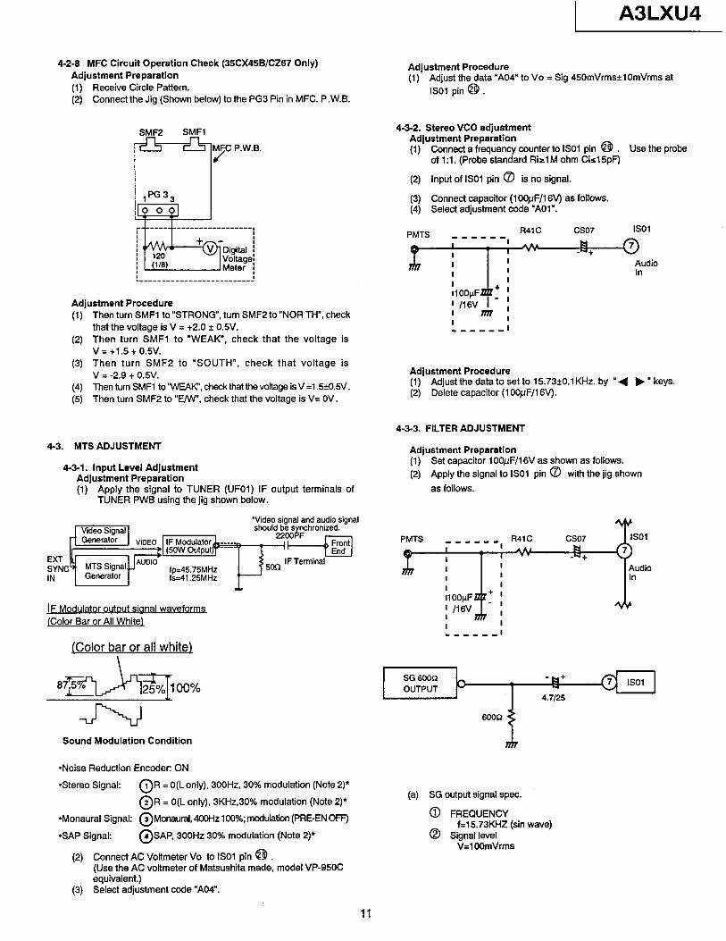
4-2-6 MFC Circuit Operation Check (35CX45B/CZ67 Only) Adjustment Preparation (1) Receive Circle Pattern. (2) Connect the Jig (Shown below) to the PG3 Pin in MFC. P .W.B.
Adjustment Procedure (1) Adjust the data “A04” to Vo = Sig 450mVrms+lOmVrms at
IS01 pin @ .
SMFP SMFl
F-77 p-w.B.
4-3-2. Stereo VCO adjustment Adjustment Preparation (1) Connect a frequency counter to IS01 pin @ . Use the probe
of 1 :l. (Probe standard Rirl M ohm Cirl5pF)
(2) Input of IS01 pin 8 is no signal.
(3) Connect capacitor (1 OOpF/16V) as follows. (4) Select adjustment code “AOl”.
PMTS _ _ _ _ _ -, R4’C cso7
Adjustment Procedure (1) Then turn SMFl to “STRONG”, turn SMF2 to “NOR TH”, check
that the voltage is V = t2.0 2 0.5V. (2) Then turn SMFl to “WEAK”, check that the voltage is
v = t1.5 + 0.5v.
IS01
JT---g*+~udio
- I I I nn : .----m I
(3) Then turn SMF2 to “SOUTH”, check that voltage is V = -2.9 t 0.5V.
(4) Then turn SMFl to ‘WEAK”, check that the voltage is V =1.5+0.5V. (5) Then turn SMF2 to “E/W’, check that the voltage is V= OV.
Adjustment Procedure (1) Adjust the data to set to 15.73?0.1 KHz. by ” ( b ” keys. (2) Delete capacitor (1 OOpF/16V).
4-3. MTS ADJUSTMENT
4-3-l. Input Level Adjustment Adjustment Preparation (1) Apply the signal to TUNER (UFOl) IF output terminals of
TUNER PWB using the jig shown below.
4-3-3. FILTER ADJUSTMENT
Adjustment Preparation (1) Set capacitor 1 OOpF/l6V as shown as follows. (2) Apply the signal to IS01 pin 0 with the jig shown
as follows.
jF Modulator output sianal waveforms jColor Bar or All White)
(Color bar or all white)
w
m-w--- l
Sound Modulation Condition
*Noise Reduction Encoder: ON
*Monaural Signal: @Monaural, 4OOHz 100%; modulation (PRE-EN OFF)
*SAP Signal: @SAP, 300Hz 30% modulation (Note 2)*
Connect AC Voltmeter Vo to IS01 pin @b . (2)
Stereo Signal: OR = O(L only), 300Hz, 30% modulation (Note 2)*
@R = O(L only), 3KHz,30% modulation (Note 2)* (a) SG output signal spec.
0 FREQUENCY f=15.73KHZ (sin wave)
0 Signal level V=l OOmVrms
(Use the AC voltmeter of Matsushita made, model VP-950C equivalent.)
(3) Select adjustment code “A04”.
11
A3LXU4 (3) Connect an AC voltmeter or oscilloscope to IS01 pin @ (4) Select adjustment code “AO3”
Adjustment Procedure
(1) Adjust the data so that the voltage of IS01 @ pin is minimum by “4 b ” keys.
4-3-4. Separation Adjustment (The adjustment of items 4-3-l to 4-3-3 should have been finished.)
Adjustment Procedure
(1) Use the same jig as input level adjustment.
(2) Connect an AC voltage meter through AUDIO AMP. to IS01 @ or connect an oscilloscope.
(3) Select adjustment code “AO6” and set data “D032”.
Adjustment Procedure
(1) Select sound output signal @ and select adjustment code “AO5” and adjust by “4 b * keys, so that 300HZ level is min. (L separation ad’ustment)
(2) Select sound input signal d 2 and select adjustment code “AO5” and adjust by “4 b n so that 3KHz level is min. (separation adjustment)
(3) Repeat (1) and (2). adjustment precision: within +ldB from min. point.
4-3-5. SAP VCO adjustment Adjustment Preparation
(1) Connect a frequency counter to IS01 @.
(2) Select adjustment Code “AO2”
Adjustment Procedure
(1) Adjustment the data by “( b ” keys so that frequency is 78.67+0.5KHz.
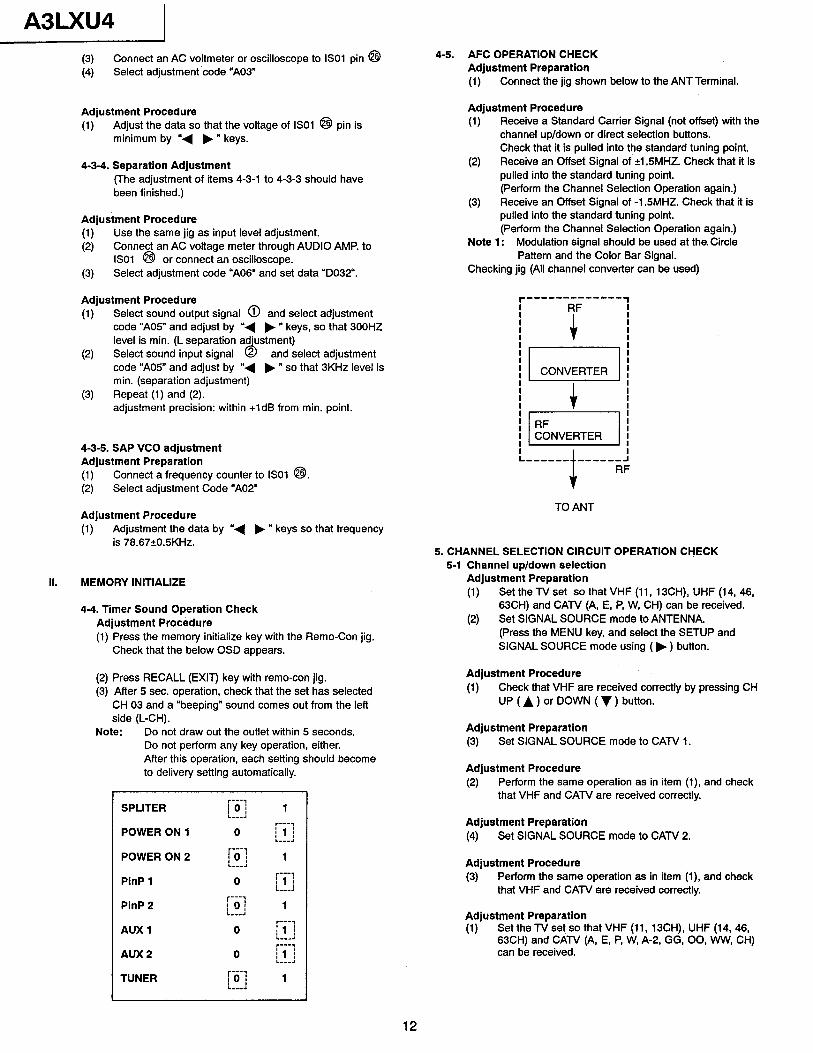
II. MEMORY INITIALIZE
4-4. Timer Sound Operation Check Adjustment Procedure (1) Press the memory initialize key with the Remo-Con jig.
Check that the below OSD appears.
(2) Press RECALL (EXIT) key with remo-con jig. (3) After 5 sec. operation, check that the set has selected
CH 03 and a “beeping” sound comes out from the left side (L-CH).
Note: Do not draw out the outlet within 5 seconds. Do not perform any key operation, either. After this operation, each setting should become to delivery setting automatically.
SPLITER
POWER ON 1
r---7 101 :---: 1
l----7 0 j 1 I
L-l
POWER ON 2 r-i-1 :-A
1
PinP 1
PinP 2
0 r---3 ;I j
r---, L---a : 01 L-A 1
AUX 1 0 r---1 i’ ! ---4 r---v
AUX 2 0 19 l----q
TUNER IO I 1 :--I
4-5. AFC OPERATION CHECK Adjustment Preparation (1) Connect the jig shown below to the ANT Terminal.
Adjustment Procedure (1) Receive a Standard Carrier Signal (not offset) with the
channel up/down or direct selection buttons. Check that it is pulled into the standard tuning point.
(4 Receive an Offset Signal of 9.5MHZ. Check that it is pulled into the standard tuning point. (Perform the Channel Selection Operation again.)
(3) Receive an Offset Signal of -15MHZ. Check that it is pulled into the standard tuning point. (Perform the Channel Selection Operation again.)
Note 1: Modulation signal should be used at the. Circle Pattern and the Color Bar Signal.
Checking jig (All channel converter can be used)
TO ANT
5. CHANNEL SELECTION CIRCUIT OPERATION CHECK 5-1 Channel up/down selection
Adjustment Preparation
(1) Set the TV set so that VHF (11, 13CH), UHF (14, 46, 63CH) and CAN (A, E, P, W, CH) can be received.
(2) Set SIGNAL SOURCE mode to ANTENNA. (Press the MENU key, and select the SETUP and SIGNAL SOURCE mode using ( b ) button.
Adjustment Procedure (1) Check that VHF are received correctly by pressing CH
UP (A) or DOWN (v) button.
Adjustment Preparation
(3) Set SIGNAL SOURCE mode to CATV 1.
Adjustment Procedure
(2) Perform the same operation as in item (1) and check that VHF and CAN are received correctly.
Adjustment Preparation
(4) Set SIGNAL SOURCE mode to CAN 2.
Adjustment Procedure
(3) Perform the same operation as in item (1) and check that VHF and CATV are received correctly.
Adjustment Preparation (1) Set the TV set so that VHF (11, 13CH), UHF (14, 46,
63CH) and CAN (A, E, P, W, A-2, GG, 00, WW, CH) can be received.
12
A3LXU4 Adjustment Procedure
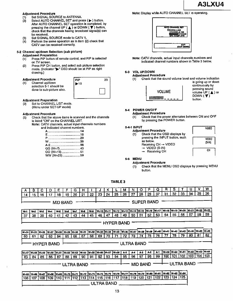
I:‘, Set SIGNAL SOURCE to ANTENNA. Select AUTO CHANNEL SET and press ( b ) button. After AUTO CHANNEL SET operation is completed, by pressing the channel UP ( A ) or DOWN ( v ) button, check that the channels having broadcast signal(s) can be received.
(3) Set SIGNAL SOURCE mode to CATV 1. (4) Perform the same operation as in item (2) check that
CATV can be received correctly.
5-2 Channel up/down Selection (sub picture) Adjustment Preparation (1) Press PIP button of remote control, and PiP is selected
on TV screen. (2) Press PIP CH button, and select sub picture selection
mode. (Indicator ‘)” OSD should be at PIP as right drawing.)
Adjustment Procedure (1) Channel up/down
selection 5-1 should be done to sub-picture also.
PiP .lO
20
El
Adjustment Preparation (2) Set to CHANNEL LIST mode.
(Menu under SET-UP mode)
Adjustment Procedure (5) Check that the above items is scanned and the channels
is listed “ON” on the CHANNEL LIST. Note: CATV channels, actual input channels numbers
and indicated channel numbers. A . . . . . . . . . . . . . . . . . . . . . . . . . . . . . . . . . . . . . . 14 E . . . . . . . . . . . . . . . . . . . . . . . . . . . . . . . ** . . . . . 18 P . . . . . . . . . . . . . ..*.*.................... 29 W . . . . . . . . . . . . . . . . . . . . . . . . . . * . . . . . . . . . . 36 A-2 . . . . . . . . . . . . . . . . . . . . . . . . . . . . . . . . . . . 98 GG (W+7) . . . . . . . . . . . . . . . . . . . . . . . . 43 00 (W+15) . . . . . . . ..*............ 51 ww (w+23) . . . . . . ..*.*.......... 59
Note: Display while AUTO CHANNEL SET is operating.
1 I ,sim”i
Note: CATV channels, actual input channels numbers and indicated channel numbers shown in Table 3 below.
5-3 VOL UP/DOWN Adjustment Procedure (1) Check that the sound volume level and volume indication
is going up or down I I continuously by
54 POWER ON/OFF Adjustment Procedure (1) Check that the power alternates between ON and OFF
by pressing the POWER button.
541 INPUT Adjustment Procedure (1) Check that the OSD displays by
pressing the INPUT button, such as below. Receivino CH + VIDEO + VlDEb (S-IN) -. Receiving CH
5-5 MENU Adjustment Procedure (1) Check that the MENU OSD displays by pressing MENU
button.
TABLE 3
AlBlClDlElF[GlHll JlKILjMINlOl-PlQlRlSlTlUlvlw, 14 1 15 1 16 I17 I18 1 19 I20 I21 I22 23 124 I25 I26 I27 I28 I29 I37 I 31 I32 I33 I34 I 35 136
I MIDBAND - SUPER BAND -
w+, 1 w+.2 1 w 1 w& 1 w+5 1 w& 1 w+7 1 w 1 w.tg 1 w+10 IW+ll Iw+12 Iw+13 Iw+14 (W+lS Iw+rs Iw+17 I w+m Iw- Iw+m lw+21 lw+= Iw+= 37 138 I39 I40 I41 1 42 14.3 I44 145 1 46 I47 I48 149 1 !jO 151 I52 I53 1 54 155 I56 I57 1 58 159
i HYPER BAND t
HYPER BAND ULTRA BAND t
Wi47 jWt49 IWt49 IW+59 IWtSl jW+52 IW+53 IW+54 IW+55 1 W+54 IW+S’ IW+55 1 A-5 1 A4 1 A-3 1 A-2 1 A-l W+59 IW+Sll IWt61 IW+52 lW+= IW+64
83(84(85186t87188)89(90191(92193194/95196197(98199 ~~tiO111~110311~1105
~IJLTRABAND - MIDBAND -kJLTRABAND -
wt65 w&6 we7 wt66 wt69 we0 w+7l w+72 w+73 w+74 w+75 W+76 w+n w+n wt79 w+a w+91 w+52 w+a? W+&(
106(107~108 tlO9 ~llO(111 I112 1113 ~114~115~116 (117 ~118~119~120 1121 112211231124 1125
ULTRA BAND t 13
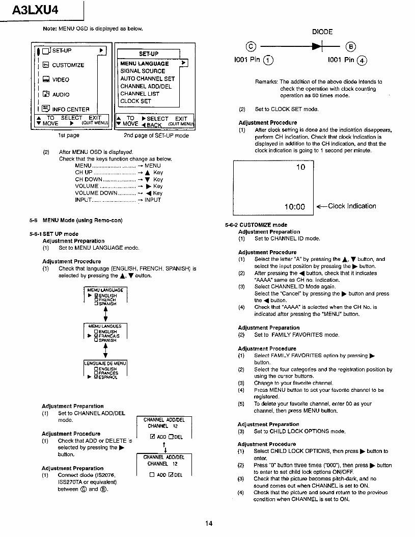
A3LXU4 Note: MENU OSD is displayed as below.
a SET-UP
I 1 m CUSTOMIZE
I 1 q VIDEO
1 st page
SET-UP 1 MENU LANGUAGE SIGNAL SOURCE AUTO CHANNEL SET CHANNEL ADD/DEL CHANNEL LIST CLOCK SET
A TO )SELECT EXIT ‘I MOVE 4 BACK (QUIT MENU:
2nd page of SET-UP mode
(2) After MENU OSD is displayed. Check that the keys function change as below.
MENU.. ........................... - MENU CH UP ............................ + A Key CH DOWN.. .................... + v Key VOLUME - ........................ b Key VOLUME DOWN.. - .......... 4 Key INPUT.. - ........................... INPUT
5-6 MENU Mode (using Remo-con)
5-6-l SET UP mode Adjustment Preparation (1) Set to MENU LANGUAGE mode.
Adjustment Procedure (1) Check that language (ENGLISH, FRENCH, SPANISH) is
selected by pressing the A, 7 button.
LENGUAJE DE MENU 0 ENGLISH Cl FRANCES
b 6aESPAfiOL
Adjustment Preparation (1) Set to CHANNEL ADD/DEL
mode.
Adjustment Procedure (1) Check that ADD or DELETE is
selected by pressing the k button.
Adjustment Preparation (1) Connect diode (fS2076,
ISS27OTA or equivalent) between @ and @J.
DIODE
@+---+-a
1001 Pin @ 1001 Pin @
Remarks: The addition of the above diode intends to check the operation with clock counting operation as 60 times mode.
(2) Set to CLOCK SET mode.
Adjustment Procedure (1) After clock setting is done and the indication disappears,
perform CH indication. Check that clock indication is displayed in addition to the CH indication, and that the clock indication is going to 1 second per minute.
IO:00 -Clock Indication
5-6-Z CUSTOMIZE mode Adjustment Preparation (1) Set to CHANNEL ID mode.
Adjustment Procedure (1) Select the letter “A” by pressing the A, v button, and
select the input position by pressing the b button. (2) After pressing the 4 button, check that it indicates
“AAAA” same as CH no. indication. (3) Select CHANNEL ID Mode again.
Select the “Cancel” by pressing the b button and press the 4 button.
(4) Check that “A&IA” is selected when the CH No. is indicated after pressing the “MENU” button.
Adjustment Preparation (2) Set to FAMILY FAVORITES mode.
Adjustment Procedure (1) Select FAMILY FAVORITES option by pressing b
button.
(2) Select the four categories and the registration position by using the cursor buttons.
(3) Change to your favorite channel.
(4) Press MENU button to set your favorite channel to be registered.
(5) To delete your favorite channel, enter 00 as your channel, then press MENU button.
Adjustment Preparation (3 Set to CHILD LOCK OPTIONS mode.
Adjustment Procedure (1) Select CHILD LOCK OPTIONS, then press b but-ton to
enter. (2) Press “0” button three times (“0007, then press b button
to enter to set child lock options ON/OFF.
(3) Check that th8 picture becomes pitch-dark, and no sound comes out when CHANNEL is set to ON.
(4) Check that the picture and sound return to the previous condition when CHANNEL is set to ON.
14
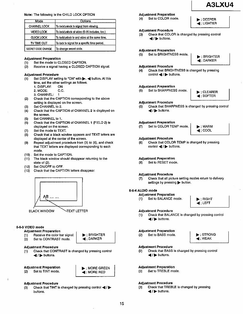
Note: The following is the CHILD LOCK OPTION
Mode Options
CHANNEL LOCK To lock/unlock tv signal from viewing.
VIDEO LOCK To lock/unlock of video (S-IN includes, too.)
QUICK LOCK To lock/unlock tv and video at the same time.
TVTlME OUT To lock tv signal for a specirIc time period.
SECRET CODE CHANGE To change secret code.
Adjustment Preparation (1) Set the mode to CLOSED CAPTION.
(2) Receive a signal having a CLOSED CAPTION signal.
Adjustment Procedure (1)
(2)
(3)
(4)
(5) (6)
(7)
(8)
(9)
(10) (11)
(12) (13)
Set DISPLAY setting to “ON” with b, 4 button. At this time, set the other settings as follows. 1. DISPLAY: ON 2. MODE: C.C. 3. CHANNEL: 1 Check that the CAPTION corresponding to the above setting is displayed on the screen. Set CHANNEL to 2. Check that the CAPTION of CHANNEL 2 is displayed on the screen. Set CHANNEL to 1. Check that the CAPTION of CHANNEL 1 (FIELD 2) is displayed on the screen. Set the mode to TEXT. Check that a black window appears and TEXT letters are displayed at the center of the screen. Repeat adjustment procedure from (3) to (6), and check that TEXT letters are displayed corresponding to each mode. Set the mode to CAPTION. The black window should disappear returning to the state of (2). Set ON/OFF to OFF. Check that the CAPTION letters disappear.
5-6-3 VIDEO mode Adjustment Preparation (1) Receive the color bar signal.
(2) Set to CONTRAST mode. b ; BRIGHTER 4 ; DARKER
Adjustment Procedure Adjustment Procedure (1) Check that CONTRAST is changed by pressing control (2) Check that BASS is changed by pressing control
4 I b buttons. 4 / b buttons.
Adjustment Preparation (4 Set to TINT mode.
Adjustment Procedure (3) Check that TINT is changed by pressing control 4 /b
buttons.
1 A3LXU4 Adjustment Preparation (4) Set to COLOR mode. b ; DEEPER
4 ; LIGHTER
Adjustment Procedure (3) Check that COLOR is changed by pressing control
( / b buttons.
Adjustment Preparation (5) Set to BRIGHTNESS mode.
Adjustment Procedure (4) Check that BRIGHTNESS is changed by pressing
control 4 I b buttons.
Adjustment Preparation (‘4 Set to SHARPNESS mode.
Adjustment Procedure (5) Check that SHARPNESS is changed by pressing control
( / b buttons.
Adjustment Preparation (7) Set to COLOR TEMP mode. b ; WARM
4 ; COOL
Adjustment Procedure (‘3) Check that COLOR TEMP is changed by pressing
control 4 / b buttons.
Adjustment Preparation (8) Set to RESET mode.
Adjustment Procedure (7) Check that all picture setting modes return to delivery
settings by pressing b button.
5-6-4 AUDIO mode Adjustment Preparation (1) Set to BALANCE mode. b ; RIGHT
+;LEFT
Adjustment Procedure (1) Check that BALANCE is changed by pressing control
4 /b buttons.
Adjustment Preparation (2) Set to BASS mode.
Adjustment Preparation (3) Set to TREBLE mode.
Adjustment Procedure (3) Check that TREBLE is changed by pressing
4 / b buttons.
15
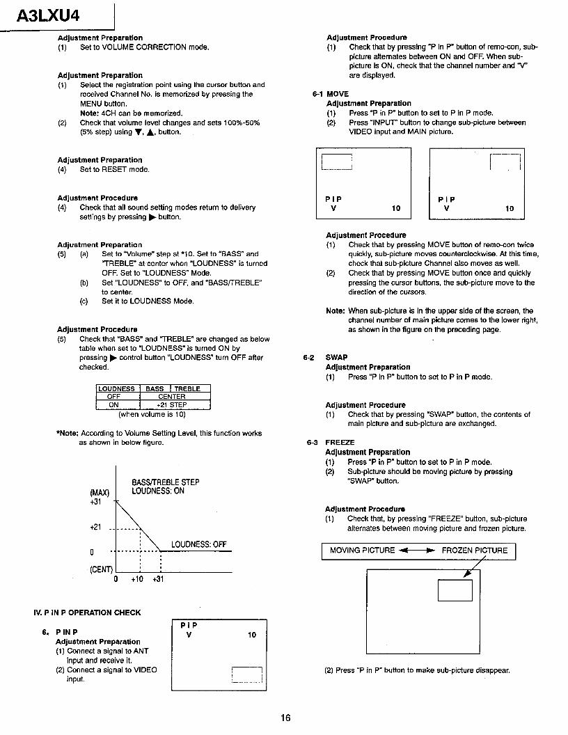
A3LXU4 Adjustment Preparation (1) Set to VOLUME CORRECTION mode.
Adjustment Preparation (1) Select the registration point using the cursor button and
received Channel No. is memorized by pressing the MENU button.
(2) Note: 4CH can be memorized. Check that volume lever changes and sets 100%~50% (5% step) using v, A, button.
Adjustment Preparation (4) Set to RESET mode.
Adjustment Procedure (4) Check that all sound setting modes return to delivery
settings by pressing b button.
Adjustment Preparation (5) (a) Set to “Volume” step at *I 0. Set to “BASS” and
“TREBLE” at-center when “LOUDNESS” is turned OFF. Set to “LOUDNESS” Mode.
03 Set “LOUDNESS” to OFF, and “BASSTTREBLE” to center.
(c) Set it to LOUDNESS Mode.
Adjustment Procedure (5) Check that “BASS” and “TREBLE” are changed as below
table when set to “LOUDNESS” is turned ON by pressing b control button “LOUDNESS” turn OFF after checked.
LOUDNESS 1 BASS 1 TREBLE OFF I CENTER ON 1 +21 STEP
(when volume is 10)
*Note: According to Volume Setting Level, this function works as shown in below figure.
IV. P IN P OPERATION CHECK
6, PIN P Adjustment Preparation (1) Connect a signal to ANT
input and receive it. (2) Connect a signal to VIDEO
input.
PIP V
Adjustment Procedure (1) Check that by pressing “P in P” button of remo-con, sub-
picture alternates between ON and OFF. When sub- picture is ON, check that the channel number and “v” are displayed.
6-1 MOVE Adjustment Preparation (1) Press “P in P” button to set to P in P mode.
(2) Press “INPUT” button to change sub-picture between VIDEO input and MAIN picture.
PIP V 10
.-_.-..-.-..- l..-.--.
! i
PIP V 10
Adjustment Procedure (1) Check that by pressing MOVE button of remo-con twice
quickly, sub-picture moves counterclockwise. At this time, check that sub-picture Channel also moves as well.
(2) Check that by pressing MOVE button once and quickly pressing the cursor buttons, the sub-picture move to the direction of the cursors.
Note: When sub-picture is in the upper side of the screen, the channel number of main picture comes to the lower right, as shown in the figure on the preceding page.
6-2 SWAP Adjustment Preparation (1) Press “P in P” button to set to P in P mode.
Adjustment Procedure (1) Check that by pressing “SWAP” button, the contents of
main picture and sub-picture are exchanged.
6-3 FREEZE Adjustment Preparation (1) Press “P in P” button to set to P in P mode. (2) Sub-picture should be moving picture by pressing
“SWAP” button.
Adjustment Procedure (1) Check that, by pressing “FREEZE” button, sub-picture
alternates between moving picture and frozen picture.
1 MOVING PICTURE - FROZEN PICTURE 1
I (2) Press “P in P” button to make sub-picture disappear.
16
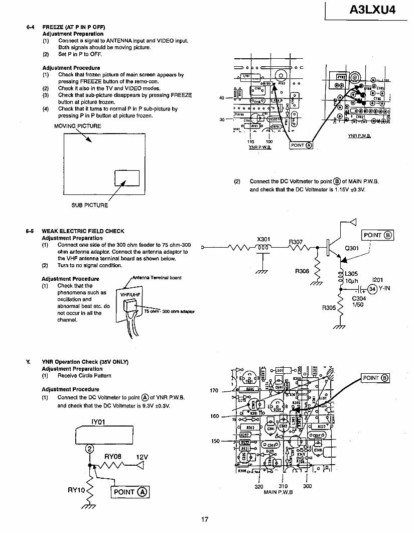
A3LXU4 64 FREEZE (AT P IN P OFF)
Adjustment Preparation (1) Connect a signal to ANTENNA input and VIDEO input.
Both signals should be moving picture.
(2) Set P in P to OFF.
Adjustment Procedure (1) Check that frozen picture of main screen appears by
pressing FREEZE button of the remo-con.
(2) Check lt also in the TV and VIDEO modes.
(3) Check that sub-picture disappears by pressing FREEZE button at picture frozen.
(4) Check that it turns to normal P in P sub-picture by pressing P in P button at picture frozen.
MOVING PICTURE
40
30
ii0 iiro YNR P.W.B.
/ )‘NR P.W.B,
(2) Connect the DC Voltmeter to point @ of MAIN P.W.B.
and check that the DC Voltmeter is 1.15V kO.3V.
/ SUB PICTURE
6-6 WEAK ELECTRIC FIELD CHECK Adjustment Preparation (1) Connect one side of the 300 ohm feeder to 75 ohm-300
ohm antenna adaptor. Connect the antenna adaptor to the VHF antenna terminal board as shown below.
(2) Turn to no signal condition.
Adjustment Procedure Antenna Terminal board
(1) Check that the phenomena such as oscillation and abnormal beat etc. do not occur in all the channel.
Y. YNR Operation Check (35V ONLY) Adjustment Preparation (1) Receive Circle Pattern
Adjustment Procedure (1) Connect the DC Voltmeter to point @of YNR P.W.B.
and check that the DC Voltmeter is 9.3V fl.3V.
0
160
320 3io 360 MAIN P.W.B
17
A3LXU4
7. FINAL ADJUSTMENT/COMMON SERVICE ADJUSTMENT
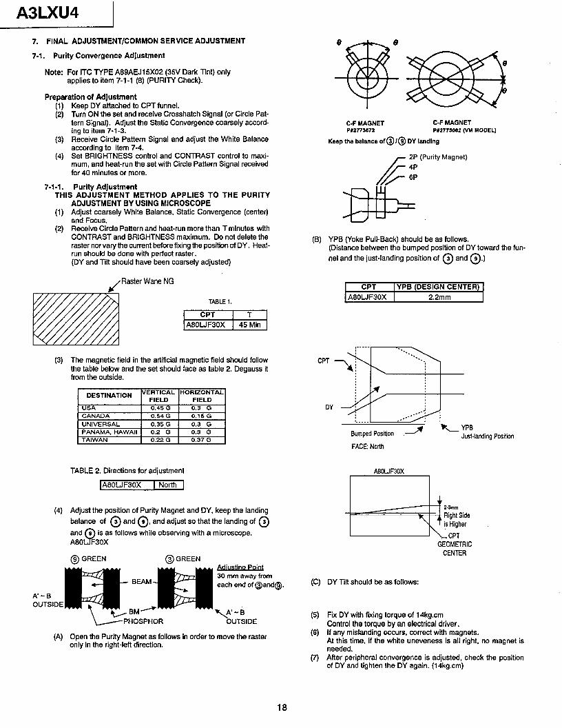
7-1. Purity Convergence Adjustment
Note: For ITC TYPE A89AEJ15XO2 (35V Dark Tint) only applies to item 7-l -1 (8) (PURITY Check).
Preparation of Adjustment
[ii
(3)
(4)
7-1-1.
Keep DY attached to CPT funnel. Turn ON the set and receive Crosshatch Signal (or Circle Pat- tern Signal). Adjust the Static Convergence coarsely accord- ing to item 7-l-3. Receive Circle Pattern Signal and adjust the White 8alance according to item 7-4. Set BRIGHTNESS control and CONTRAST control to maxi- mum, and heat-run the set with Circle Pattern Signal received for 40 minutes or more.
Purity Adjustment THIS ADJUSTMENT METHOD APPLIES TO THE PURITY
ADJUSTMENT BY USING MICROSCOPE (1) Adjust coarsely White Balance, Static Convergence (center)
and Focus. (2) Receive Circle Pattern and heat-run more than T minutes with
CONTRAST and BRIGHTNESS maximum. Do not delete the raster nor vary the current before fixing the position of DY. Heat- run should be done with perfect raster. (DY and Tilt should have been coarsely adjusted)
L( Raster Wane NG
(3)
(4)
T4BLEl.
1 CPT I T 1 1A8OLJF3OX 1 45 Min 1
The magnetic field in the artificial magnetic field should follow the table below and the set should #ace as table 2. Degauss it from the outside.
DEST,NAT,ON VERTICAL HORIZONTAL FIELD FIELD
USA 0.45 G 0.3 G
TABLE 2. Directions for adjustment
IA80LJF30X 1 North [
Adjust the position of Purity Magnet and DY, keep the landing balance of @ and @, and adjust so that the landing of @
and 9
9 is as follows while observing with a microscope. A80 F3OX
@ GREEN @ GREEN
\PHOSPHOR -OUTSIDE
(A) Open the Purity Magnet as follows in order to move the raster only in the right-left direction.
C-F MAGNET P#2773672
C-F MAGNET P#2775052 (VM YODEL)
Keep the balance of @ I@ DY landing
/k 2P
/#- i;
(Purity Magnet)
(B) YPB (Yoke Pull-Back) should be as follows. (Distance between the bumped position of DY toward the fun- nel and the just-landing position of @ and a.)
CPT jYPB (DESIGN CENTER) A80LJF30X j 2.2mm
(C)
(5)
(6)
(7)
FACE: North
A8OWF3OX
GEOMETRIC CENTER
DY Tilt should be as follows:
Fix DY with fixing torque of 14kg.cm Control the torque by an electrical driver. If any mislanding occurs, correct with magnets. At this time, if the white uneveness is all right, no magnet is needed. After peripheral convergence is adjusted, check the position of DY and tighten the DY again. (14kg.cm)
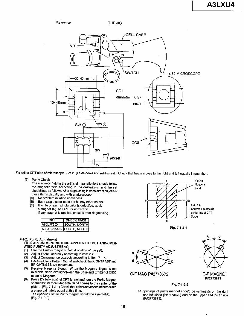
Reference THE JIG
3 /CELL-CASE
A3LXU4
Fix coil to CRT side of microscope. Set it up side down and measure it. Check that beam moves to the right and left equally in quantity .
(8) Purity Check The magnetic field in the artificial magnetic field should follow the magnetic field according to the destination, and the set should face as follows. After degaussing in each direction, check these items visually and with a microscope.
(A) No problem in white uneveness. (B) Each single color must not hit any other colors. (C) If white or each single color is defective, apply
a magnet (S) on CPT for correction. If any magnet is applied, check it afler degaussing.
7-l-2. Purity Adjustment (THIS ADJUSTMENT METHOD APPLIES TO THE HAND-OPER- ATED PURITY ADJUSTMENT.) (1) I:; (4)
(5)
(6)
Use the Earth’s magnetic ield (Location of the set). Adjust Focus coarsely according to item 7-2. Adjust Convergence coarsely according to item 7-l -4. Receive Circle Pattern Signal and check that CONTRAST and BRIGHTNESS are maximum. Receive Magenta Signal. When the Magenta Signal is not available, short-circuit between the Base and Emitter of Cl855 to set to Magenta. Press DY fully against CPT funnel and turn the Purity Magnet so that the Vertical Magenta Band comes to the center of the picture. (Fig. 7-l -2-l) Check that color uneveness of both sides are approximately equal at this time. The openings of the Purity magnet should be symmetric. (Fig. 7-i-2-2)
b Vertical Magenta Band
a a-a’, bb Show the geometric center line of CPT Screen
b
Fig. 7-l-2-1
e e
@ C-F MAG P#2773672 C-F MAGNET
P#2773671
Fig. 7-l-2-2
The openings of purity magnet should be symmetric on the right and left sides (P#2773672) and on the upper and lower side (P#2773671).
19
A3LXU4
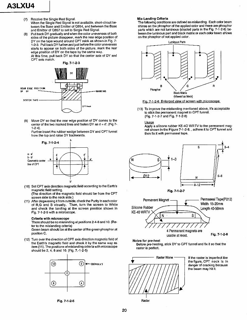
(7) Receive the Single Red Signal. When the Single Red Signal is not available, short-circuit be- tween the Base and Emitter of Q854, and between the Base and Emitter of Q857 to set to Single Red Signal.
(8) Pull back DY gradually and when the color uneveness of both sides of the picture disappear, mark the rear,edge position of DY on the tape wound around CPT neck as shown in Fig. 7- l-2-3. Pull back DY further and just before the color uneveness starts to appear on both sides of the picture, mark the rear edge position of DY on the tape by the same way. At this time, pull back DY so that the center axis of DY and CPT axis match.
Fig. 7-l-2-3
REAR EDGE PDS DF DV
SCOTCH TAPE
.YARKINC
(9) Move DY so that the rear edge position of DY comes to the center of the two marked lines and fasten DY as d = d’. (Fig 7- l-2-4). Further insert the rubber wedge between DY and CPTfunnel from the top and raise DY backwards.
Fig. 7-l-2-4 P
(10) Set CPT axis direction magnetic field according to the Earth’s magnetic field setting. (The direction of the magnetic field should be from the CPT screen side to the neck side.)
(11) After degaussing it from outside, check the Purity in each color of R,G and B visually. Then, turn the screen to White and check the landing at the screen position shown in Fig. 7-l-2-5 with a microscope.
Criteria with microscope There should be no mislanding at positions 2-4-8 and 10. (Re- fer to the mislanding criteria) Green beam should be at the center of the green phosphor at position C.
(12) Turn over the direction of CPT axis direction magnetic field of the Earth’s magnetic field and check it by the same way as item (11). The positions of mislanding criteria with microscope should be 2, 4, 8 and 10. (Fig. 7.-l -2-5)
, @ 0 2 +060mmx5
(c>
,o a,
Mis-Landing Criteria The following conditions are defined as mislanding. Each color beam shines on the phosphor of the applied color and there are phosphor parts which are not luminous (shaded parts in the Fig. 7-l -2-6) be- tween the luminous part and black matrix or each color beam shines on the phosphor of not applied color.
Luminous Parts
Phosphor Black Matrix vewed as black)
Fia. 7-l-2-6 Enlaraed view of screen with microscooe
(13) To improve the mislanding mentioned above, it’s acceptable to stick the permanent magnet to CPT funnel. (Fig. 7-l -2-7 and Fig. 7-l -2-8)
Apply a silicone rubber KE-40 WRTV to the permanent mag- net shown in the Figure 7-l -2-8. , adhere it to CPT funnel and then fix it with permaseal tape.
Fig. 7-l-2-7
4 Permanent magnets are usable at most. Fig. 7-l-2-8
Notes for pre-heat Before pre-heating, stick DY to CPT funnel and fix it so that the raster is perfect.
If the raster is imperfect like the figure, CPT neck is in danger of cracking because the beam may hit it.
Fig. 7-l-2-5 Raster
20
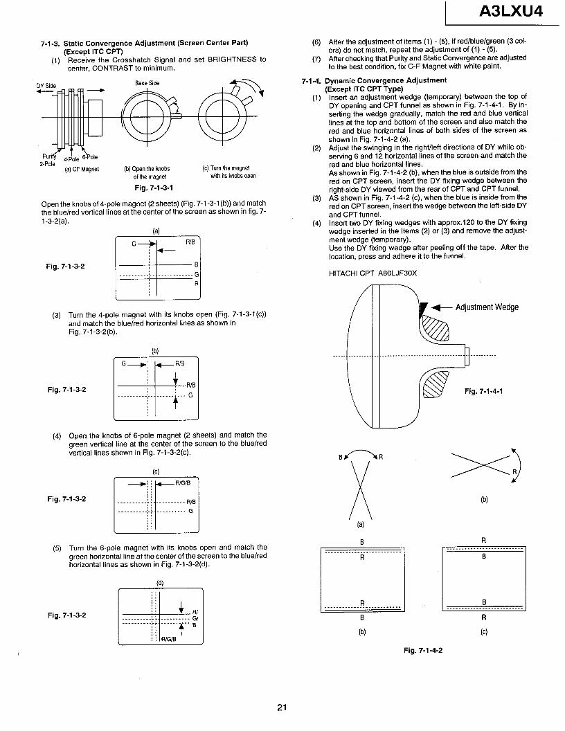
7-l-3. Static Convergence Adjustment (Screen Center Part) (Except ITC CPT)
(1) Receive the Crosshatch Signal and set BRIGHTNESS to center, CONTRAST to minimum.
DY Side
(a) CF Magnet
Base Side
(b) Open the knobs of the magnet
(c) Turn the magnet with its knobs open
Fig. 7-l -3-l
Open the knobs of 4-pole magnet (2 sheets) (Fig. 7-l -3-l (b)) and match the blue/red vertical lines at the center of the screen as shown in fig. 7- 1 -3-2(a).
la)
Fig. 7-l -3-2
(3) Turn the 4-pole magnet with its knobs open (Fig. 7-1-3-1 (c)) and match the blue/red horizontal lines as shown in Fig. 7-1-3-2(b).
(‘4 G--+ /+--RR/B
Fig. 7-l-3-2
(4) Open the knobs of 6-pole magnet (2 sheets) and match the green vertical line at the center of the screen to the blue/red vertical lines shown in Fig. 7-l -3-2(c). (a
Fig. 7-l -3-2
(5) Turn the 6-pole magnet with its knobs open and match the green horizontal line at the center of the screen to the blue/red horizontal lines as shown in Fig. 7-1-3-2(d).
Cd)
Fig. 7-l-3-2
A3LXU4
(6) After the adjustment of items (1) - (5), if red/blue/green (3 col- ors) do not match, repeat the adjustment of (1) - (5).
(7) After checking that Purity and Static Convergence are adjusted to the best condition, fix C-F Magnet with white paint.
7-l-4. Dynamic Convergence Adjustment (Except ITC CPT Type)
(1) Insert an adjustment wedge (temporary) between the top of DY opening and CPT funnel as shown in Fig. 7-l -4-l. By in- serting the wedge gradually, match the red and blue vertical lines at the top and bottom of the screen and also match the red and blue horizontal lines of both sides of the screen as shown in Fig. 7-1-4-2 (a).
(2) Adjust the swinging in the right/left directions of DY while ob- serving 6 and 12 horizontal lines of the screen and match the red and blue horizontal lines. As shown in Fig. 7-i-4-2 (b), when the blue is outside from the red on CPT screen, insert the DY fixing wedge between the right-side DY viewed from the rear of CPT and CPT funnel.
(3) AS shown in Fig. 7-1-4-2 (c), when the blue is inside from the red on CPT screen, insert the wedge between the left-side DY and CPT funnel.
(4) Insert two DY fixing wedges with approx.120 to the DY fixing wedge inserted in the Items (2) or (3) and remove the adjust- ment wedge (temporary). Use the DY fixing wedge after peeling off the tape. After the location, press and adhere it to the funnel.
HITACHI CPT A80LJF30X
+- Adjustment Wedge
Fig. 7-1-4-l
B/--W
~ (4
B _________________---______
R
-----I R B _________________-_------- __________________________ B R
04 (4
Fig. 7-1-4-2
21
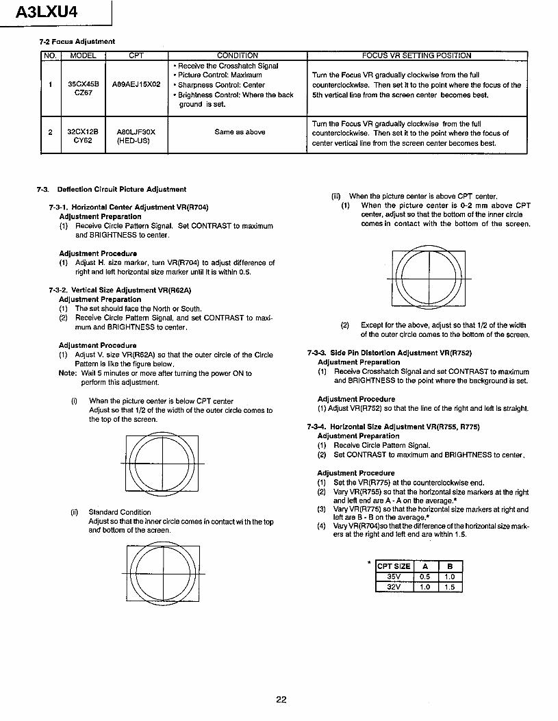
A3LXU4 I 7-2 Focus Adjustment
NO. MODEL CPT CONDITION FOCUS VR SETTING POSITION l Receive the Crosshatch Signal l Picture Control: Maximum Turn the Focus VR gradually clockwise from the full
1 35CX45B A89AEJ 15X02 l Sharpness Control: Center counterclockwise. Then set it to the point where the focus of the
1 cz67 1 l Brightness Control: Where the back
1 ground is set. 5th vertical line from the screen center becomes best.
Turn the Focus VR gradually clockwise from the full counterclockwise. Then set it to the point where the focus of center vertical line from the screen center becomes best.
7-3. Deflection Circuit Picture Adjustment
7-3-l. Horizontal Center Adjustment VR(R704) Adjustment Preparation (1) Receive Circle Pattern Signal. Set CONTRAST to maximum
and BRIGHTNESS to center.
Adjustment Procedure (1) Adjust H. size marker, turn VR(R704) to adjust difference of
right and left horizontal size marker until it is within 0.5.
7-3-2. Vertical Size Adjustment VR(R62A) Adjustment Preparation (1) The set should face the North or South. (2) Receive Circle Pattern Signal, and set CONTRAST to maxi-
mum and BRIGHTNESS to center.
Adjustment Procedure (1) Adjust V. size VR(R62A) so that the outer circle of the Circle
Pattern is like the figure below, Note: Wait 5 minutes or more after turning the power ON to
perform this adjustment.
(i) When the picture center is below CPT center Adjust so that l/2 of the width of the outer circle comes to the top of the screen.
(ii) Standard Condition Adjust so that the inner circle comes in contact wi th the top and bottom of the screen.
(iii) When the picture center is above CPT center. (1) When the picture center is O-2 mm above CPT
center, adjust so that the bottom of the inner circle comes in contact with the bottom of the screen.
(2) Except for the above, adjust so that l/2 of the width of the outer circle comes to the bottom of the screen.
73-3. Side Pin Distortion Adjustment VR(R752) Adjustment Preparation (1) Receive Crosshatch Signal and set CONTRAST to maximum
and BRIGHTNESS to the point where the background is set.
Adjustment Procedure (1) Adjust VR(R752) so that the line of the right and left is straight.
7-3-4. Horizontal Size Adjustment VR(R755, R775) Adjustment Preparation (1) Receive Circle Pattern Signal. (2) Set CONTRAST to maximum and BRIGHTNESS to center.
Adjustment Procedure (1) Set the VR(R775) at the counterclockwise end. (2) Vary VR(R755) so that the horizontal size markers at the right
and left end are A -A on the average.* (3) Vary VR(R775) so that the horizontal size markers at right and
lefl are B - B on the average.* (4) VaryVR(R704)so that the difference of the horizontal size mark-
ers at the right and left end are within 1.5.
L 32V Il.0 Il.51
22
A3LXU4
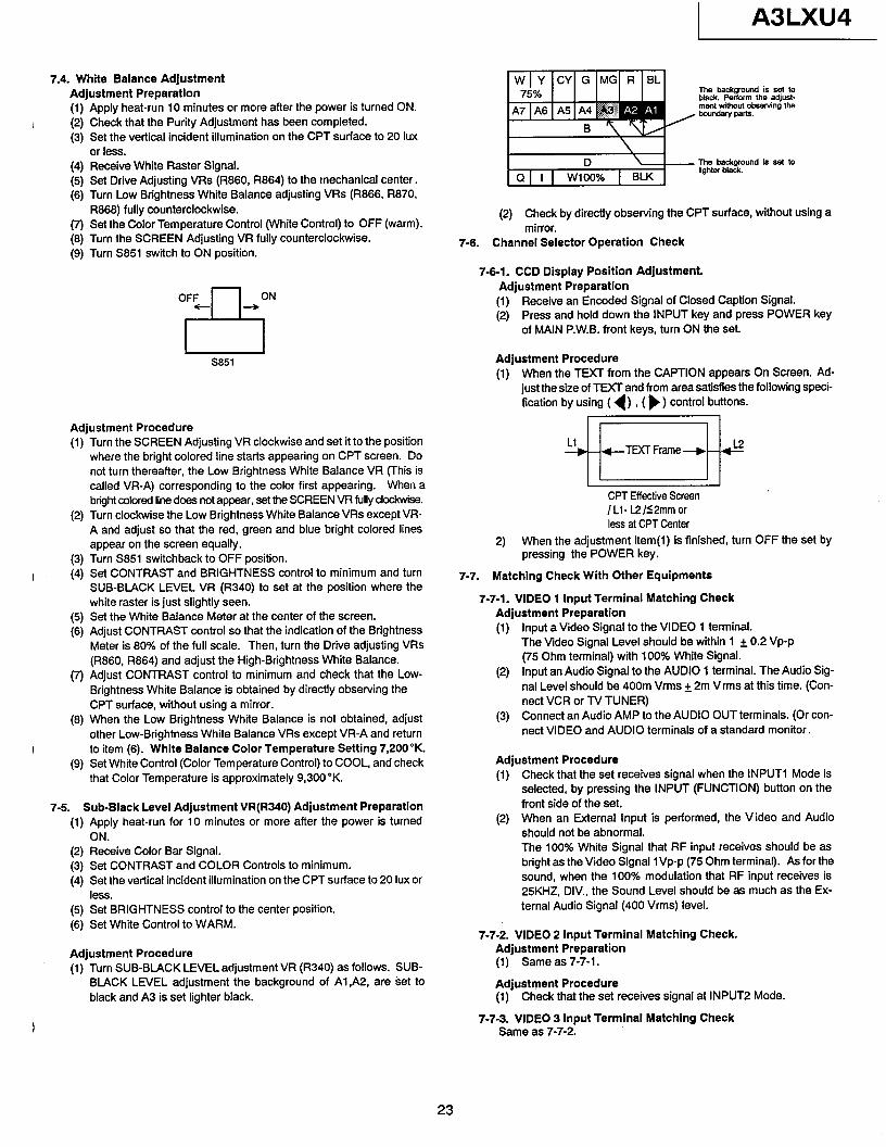
7.4. White Balance Adjustment Adjustment Preparatlon
(1) (2) (3)
Apply heat-run 10 minutes or more after the power is turned ON. Check that the Purity Adjustment has been completed. Set the vertical incident illumination on the CPT surface to 20 Iux or less.
(4) (5) (6)
Receive White Raster Signal. Set Drive Adjusting VRs (R660, R864) to the mechanical center. Turn Low Brightness White Balance adjusting VRs (R866, R870, R868) fully counterclockwise.
(7) Set the Color Temperature Control (White Control) to OFF (warm). 03) Turn the SCREEN Adjusting VR fully counterclockwise. (9) Turn S851 switch to ON position.
S851
Adjustment Procedure
(1)
(2)
(3)
I (4)
(5) (‘3
(7)
(8)
I (9)
Turn the SCREEN Adjusting VR clockwise and set it to the position where the bright colored line starts appearing on CPT screen. Do not turn thereafter, the Low Brightness White Balance VR (This is called VR-A) corresponding to the color first appearing. When a bright colored line does not appear, set the SCREEN VR fully clockwise. Turn clockwise the Low Brightness White Balance VRs except VR- A and adjust so that the red, green and blue bright colored lines appear on the screen equally. Turn S851 switchback to OFF position. Set CONTRAST and BRIGHTNESS control to minimum and turn SUB-BLACK LEVEL VR (R340) to set at the position where the white raster is just slightly seen. Set the White Balance Meter at the center of the screen. Adjust CONTRAST control so that the indication of the Brightness Meter is 80% of the full scale. Then, turn the Drive adjusting VRs (R860, R864) and adjust the High-Brightness White Balance. Adjust CONTRAST control to minimum and check that the Low- Brightness White Balance is obtained by directly observing the CPT surface, without using a mirror. When the Low Brightness White Balance is not obtained, adjust other Low-Brightness White Balance VRs except VR-A and return to item (6). White Balance Color Temperature Setting 7,200% Set White Control (Color Temperature Control) to COOL, and check that Color Temperature is approximately 9,300”K.
7-5. Sub-Black Level Adjustment VR(R340) Adjustment Preparation
(1) Apply heat-run for 10 minutes or more after the power is turned ON.
(2) (3) (4)
Receive Color Bar Signal. Set CONTRAST and COLOR Controls to minimum. Set the vertical incident illumination on the CPT surface to 20 Iux or less.
(5) Set BRIGHTNESS control to the center position.
(6) Set White Control to WARM.
Adjustment Procedure (1) Turn SUB-BLACK LEVEL adjustment VR (R340) as follows. SUB-
BLACK LEVEL adjustment the background of Al&Z, are set to black and A3 is set lighter black.
(2) Check by directly observing the CPT surface, without using a mirror.
7-6. Channel Selector Operation Check
7-6-l. CCD Display Position Adjustment. Adjustment Preparation
(1) Receive an Encoded Signal of Closed Caption Signal. (2) Press and hold down the INPUT key and press POWER key
of MAIN P.W.B. front keys, turn ON the set.
Adjustment Procedure (1) When the TEXT from the CAPTION appears On Screen. Ad-
just the size of TEXT and from area satisfies the following speci- fication by using ( ( ) , ( ) ) control buttons.
I-I Ll +H +-TEXT Frame + H &
- CPT Effective Screen /Ll- L2/<2mm or less at CPT Center
2) When the adjustment item(l) is finished, turn OFF the set by pressing the POWER key.
7-7. Matching Check With Other Equipments
7-7-l. VIDEO 1 Input Terminal Matching Check Adjustment Preparation (1)
(2)
(3)
Input a Video Signal to the VIDEO 1 terminal. The Video Signal Level should be within 1 + 0.2 Vp-p (75 Ohm terminal) with 100% White Signal. Input an Audio Signal to the AUDIO 1 terminal. The Audio Sig- nal Level should be 400m Vrms + 2m Vrms at this time. (Con- nect VCR or TV TUNER) Connect an Audio AMP to the AUDIO OUT terminals. (Or con- nect VIDEO and AUDIO terminals of a standard monitor.
Adjustment Procedure (1) Check that the set receives signal when the INPUT1 Mode is
selected, by pressing the INPUT (FUNCTION) button on the front side of the set.
(2) When an External Input is performed, the Video and Audio should not be abnormal. The 100% White Signal that RF input receives should be as bright as the Video Signal IVp-p (75 Ohm terminal). As for the sound, when the 100% modulation that RF input receives is 25KH2, DIV.. the Sound Level should be as much as the Ex- ternal Audio Signal (400 Vrms) level.
7-7-2. VIDEO 2 Input Terminal Matching Check. Adjustment Preparation (1) Same as 7-7-l.
Adjustment Procedure (1) Check that the set receives signal at INPUT2 Mode.
7-7-3. VIDEO 3 Input Terminal Matching Check Same as 7-7-2.
23
A3LXU4
7-7-4. S-IN input terminal Matching check. Adjustment Preparation (1) Connect the Video/Chroma Signal to S-IN terminal. (2) Connect the Sound Signal to AUDIO 1 input terminals.
Adjustment Procedure (1) Check that the set receives signal at S-IN Mode.
7-7-5. AUDIO Output Level Check Adjustment Preparation (1) Input the same Audio Signal as Item 7-7-l (2) to AUDIO IN
terminal(L). At this time, connect nothing to R terminal. (2) Input the same Audio Signal as Item 7-7-l (2) to AUDIO IN
terminal (R). At this time, connect nothing to L terminal. (3) Check that the Normal Sound is output from both sides of the
speakers when signal in item (1) is input. (4) Check that the Normal Sound is output from only the right ((R)
speaker when signal in Item (2) is input.
Adjustment Procedure (1) Check that the Audio Output of AUDIO AMP connected to
AUDIO Hi-Fi OUT terminals or monitor changes according to the “VOLUME” of the set
(2) Confirm that the Output Level of item(l) should be 1Vrms (2.8 Vp-p) +20%. (Above level is equivalent to maximum VOL- UME,lOO% Modulated Signal Input.)
7-8. Safety Check
7-8-l. Polarity Check There should be electricity between AC Power Cord and Chassis Earth.
7-9. MTS Operation Check
7-9-l. STEREO/SAP Broadcast Receiving Check
Adjustment Preparation (1) Set the set so that a MTS Broadcast (STEREO/SAP) can be
received. (2) Set MTS Mode to STEREO or SAP Mode.
Note: To select between “STEREO/SAP”, display sound setting of MTS Mode and select SOUND MENU.
(3) Set BALANCE to the center.
Adjustment Procedure (1) When one of the MTS Broadcast Stereo or SAP is received,
check that “ST” or “SA” is displayed on the screen.
STEREO or SAP
11 ST
or SA
(2) STEREO Broadcast Receiving Check (I) Select MTS Mode and press Cursor ( b) button to display
“STEREO” on the screen (II) When only Lch signal is received, Lch sound comes out
from the left speaker. (Ill) When only Rch signal is received, Rch sound comes out
from the right speaker. (IV) When Monaural Signal is received, Monaural Sound
comes out from both of the right and left speakers. (3) SAP Broadcast Receiving Check
(I) Select MTS Mode and press Cursor ( b) button to display “SAP” on the screen.
(II) SAP signal comes out from both of the right and left speak- ers.
(Ill) When no SAP signal, the sound on “MAIN” side comes out.
Note: When the Channel selection is performed or RECALL button is operated “ST” or “SA” is shown below the Channel No. ( For approximately 5 seconds)
7-9-2. MTS Mode Check Adjustment Preparation (1) Set the set so that a MTS Broadcast (STEREO/SAP) can be
received. (2) Set BALANCE to the center.
7-10.
7-11.
Adjustment Procedure (1)’ When “MTS MODE” Mode is set to “MONO” side, check that
STEREO and MONO indication lamps which have been ON are turned OFF and that Monaural Sound comes out from the right and left speakers.
(2) When “MIS MODE” Mode is set to “STEREO” side, check that STEREO and MONO indication lamps which have been OFF are turned ON and that STEREO and SAP sound can be received.
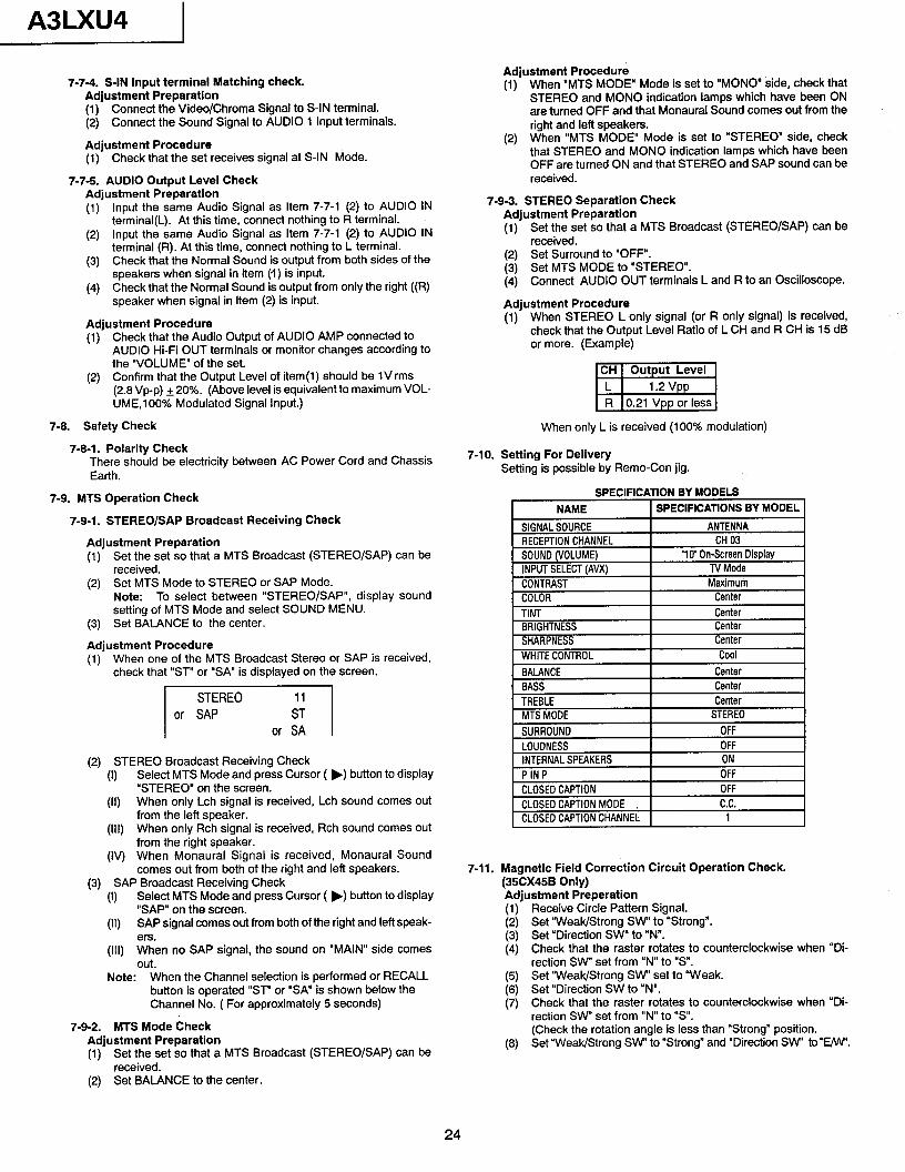
7-9-3. STEREO Separation Check Adjustment Preparation (1) Set the set so that a MTS Broadcast (STEREO/SAP) can be
received. (2) Set Surround to “OFF”. (3) Set MTS MODE to “STEREO”. (4) Connect AUDIO OUT terminals L and R to an Oscilloscope.
Adjustment Procedure (1) When STEREO L only signal (or R only signal) is received,
check that the Output Level Ratio of L CH and R CH is 15 dB or more. (Example)
mi When only L is received (100% modulation)
Setting For Delivery Setting is possible by Remo-Con jig.
SPECIFICATION BY MODELS I NAME j SPECIFICATIONS BY MODEL 1
SIGNALSOURCE RECEPTIONCHANNEL SOUND(VOLUME) INPUTSELECTIAVX)
J ANTENNA
CH03 'lo' On-Screen Display
TVMode
CONTRAST I Maximum COLOR Center TINT BRIGHTNESS SHARPNESS
Center Center Center
..__-- MTSMODE I STEREO I
SURROUND I OFF I LOUDNESS INTERNALSPEAKERS PINP
CLOSEDCAPTION CLOSEDCAPTIONMODE , CLOSEDCAPTIONCHANNEL
OFF ON OFF
OFF C.C.
1
Magnetic Field Correction Circuit Operation Check. (35CX45B Only) Adiustment Preperation
Receive Circle Pattern Signal. Set “Weak/Strong SW to “Strong”. Set “Direction SW” to “N”. Check that the raster rotates to counterclockwise when “Di- rection SW set from “N” to “s”. Set “Weak/Strong SW” set to ‘Weak. Set “Direction SW to “N”. Check that the raster rotates to counterclockwise when “Di- rection SW” set from “N” to “s”. (Check the rotation angle is less than “Strong” position. Set “Weak/Strong SW’ to “Strong” and “Direction SW’ to “w.
24
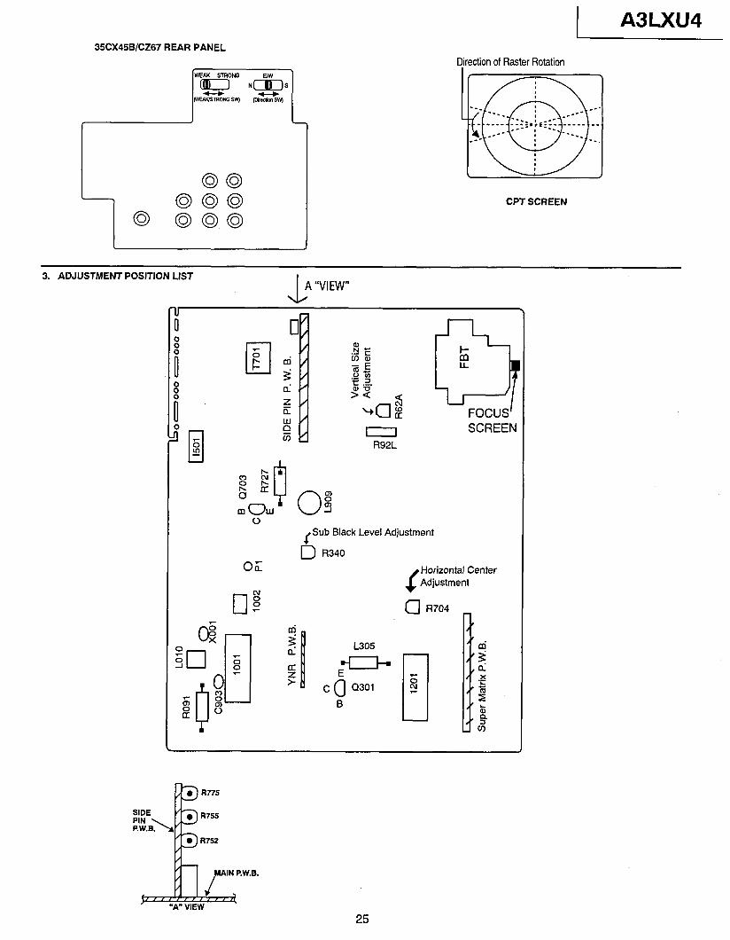
A3LXU4 35CX45B/CZ67 REAR PANEL
-
Qirection of Raster Rotation
--- --._
ITI
: *- _ ____ ::::.,rzz- __-- -_-- ._
--- Q
--. _*-- -_--- _-
: ---__ --.
CPT SCREEN
3. ADJUSTMENT POSITION LIST
FOCUS’ SCREEN
f Sub Black Level Adjustment
D R340
f
Horizontal Center Adjustment
a R704 -
25
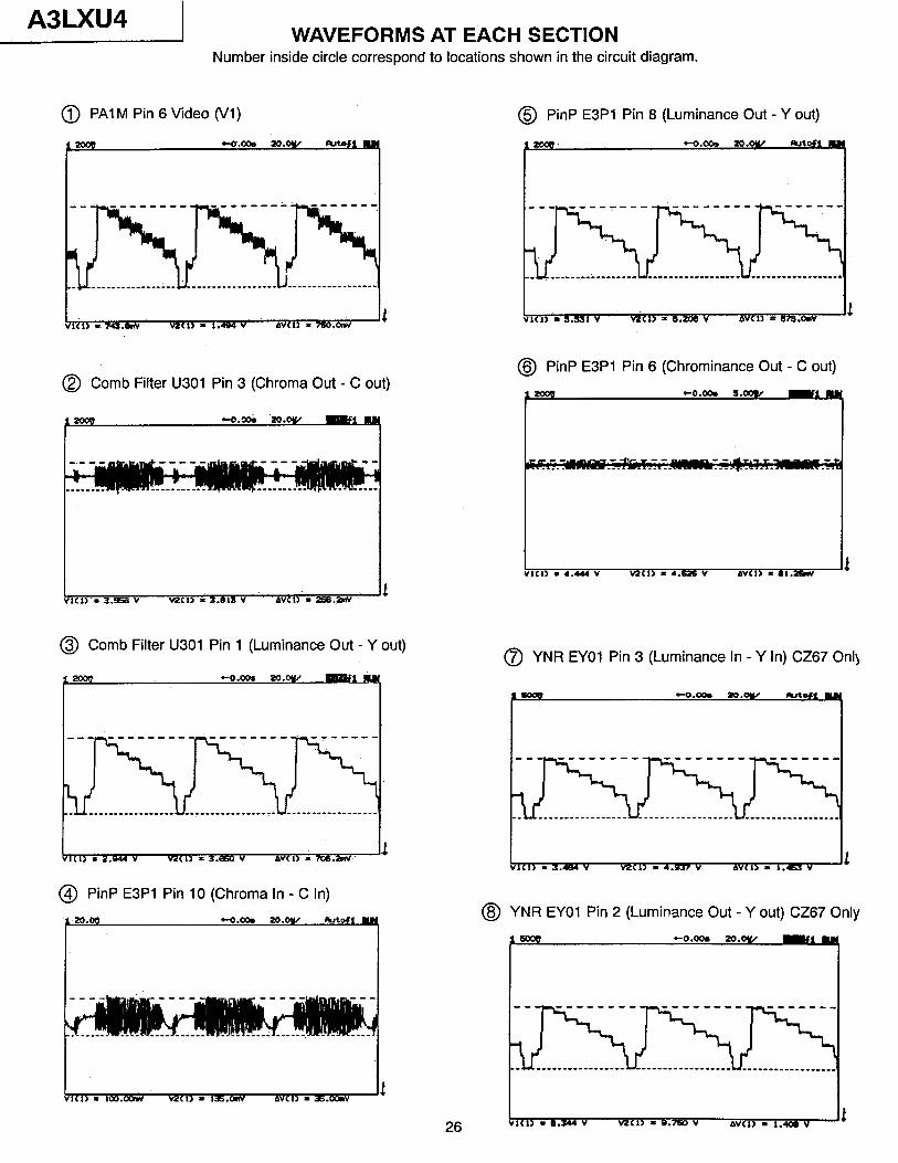
A3LXU4 1 WAVEFORMS AT EACH SECTION
Number inside circle correspond to locations shown in the circuit diagram.
@ PA1 M Pin 6 Video (I/l)
It VI<l> * 743.amv v2Cl) = 1.494 v AWL) - 76o.cmv
@ Comb Filter U301 Pin 3 (Chroma Out - C out)
1<w. 3.568 v M‘I, I 3.813 V ‘AVCO I 29B.ZnV
@ Comb Filter U301 Pin 1 (Luminance Out - Y out)
Ii lCl> = 2.044 v VaCl, L 3.a v AVCI) = 706.&V
@ PinP E3Pl Pin 10 (Chroma In - C In)
26
@ PinP E3Pl Pin 8 (Luminance Out - Y out)
@ PinP E3Pl Pin 6 (Chrominance Out - C out)
rota +o.oom s.cow
t
0 YNR EYOI Pin 3 (Luminance In - Y In) CZ67 Only
@ YNR EYOl Pin 2 (Luminance Out - Y out) CZ67 Only
+0.009 2o.ov
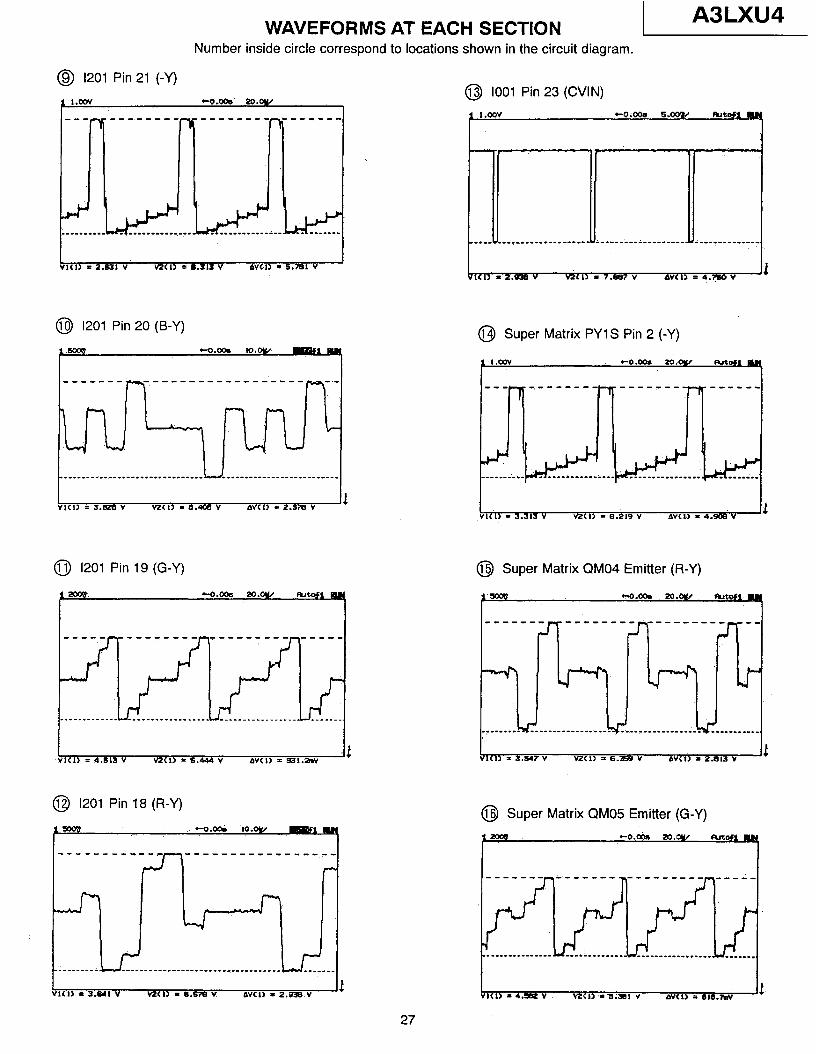
WAVEFORMS AT EACH SECTION 1 A3LXU4
Number inside circle correspond to locations shown in the circuit diagram.
@ 1201 Pin 21 (-Y)
l.cov ~Q.oQb w.ow I
1 I VI(l) = 2.621 v v2(1> q 3.313 v 6VCll = 5.781 v
@ 1201 Pin 20 (B-Y)
?” co.Qh 1o.w
----.--- -----------------
VI(I> 3 313 v - . ncr, - a.219 Y AVCO = 4.M V
0 1201 Pin 19 (G-Y) @I Super Matrix QM04 Emitter (R-Y)
= 4.813 v v2cn = 5.444 v Awl> = B31.2w
@ 1201 Pin 18 (R-Y)
+-o.u% ,o.oy/
l(l) = 3.811 v MXI> rB.wBV PVCI~ - 2.998 v Jr
@ 1001 Pin 23 (CVIN)
<ia =z.RQ)v MCl> = 7.887 v AVv(I> = 4.?50 V Jr
@I Super Matrix PYlS Pin 2 (-Y)
, 3.547v = VzCll = 6.W ” bvc~> = z.aw v Ir
@ Super Matrix QM05 Emitter (G-Y)
+o.& w.Dy/ altla#l
I v1c1a - 4.3fI2 v MCI> -= s;wBI v bVCl> = BlB.7#
27
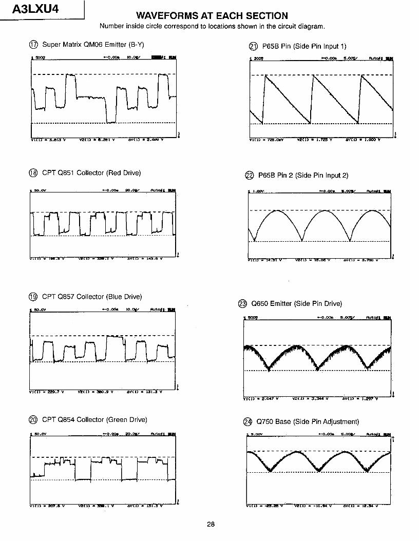
A3LXU4 WAVEFORMS AT EACH SECTION
Number inside circle correspond to locations shown in the circuit diagram.
0 Super Matrix QM06 Emitter (B-Y) @ P65B Pin (Side Pin Input 1)
@ CPT Q851 Collector (Red Drive) @I P65B Pin 2 (Side Pin Input 2)
@ CPT Q857 Collector (Blue Drive)
I “ICI, = Pg.7 v v?xI> =sID.5v OVCI, = ls1.1 v
@I CPT Q854 Collector (Green Drive)
___________________ --_____-_-_-
@I Q650 Emitter (Side Pin Drive)
1 VlCl> = z.047 v MCI> = 3.344 v GwCl) = 1297v
.Ir
@I Q750 Base (Side Pin Adjustment)
$ +o.cxh 6roonC eutofi M S.OOV I t
28
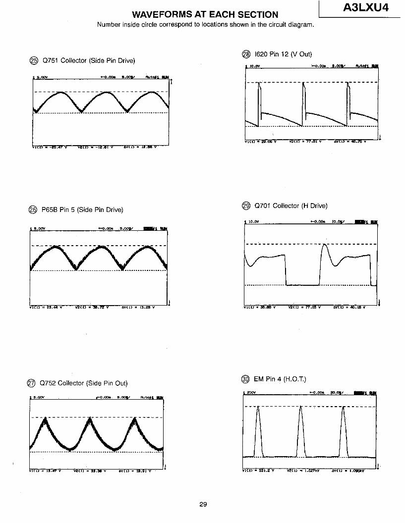
WAVEFORMS AT EACH SECTION 1 A3LXU4
Number inside circle correspond to locations shown in the circuit diagram.
@ Q751 Collector (Side Pin Drive)
@ P65B Pin 5 (Side Pin Drive)
------ ------
__________.__- __--_--___--.-
@ Q752 Collector (Side Pin Out)
@ 1620 Pin 12 (V Out)
@I Q701 Collector (H Drive)
$ 1o.w +o.m¶ lO.ay/ ‘911M
------------------
@ EM Pin 4 (H.O.T.)
co.oos aa.q/
29
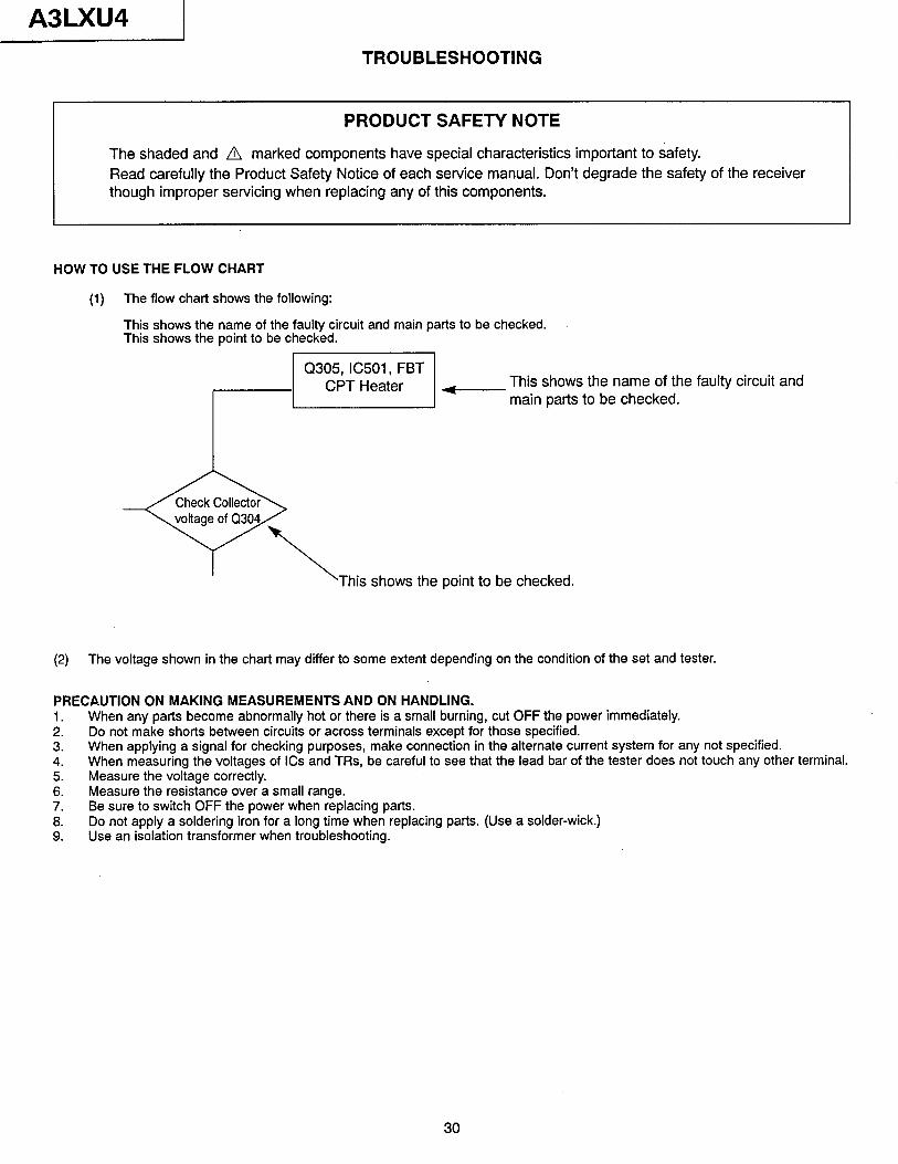
A3LXU4 1 TROUBLESHOOTING
PRODUCT SAFETY NOTE
The shaded and A marked components have special characteristics important to safety. Read carefully the Product Safety Notice of each service manual. Don’t degrade the safety of the receiver though improper servicing when replacing any of this components.
HOW TO USE THE FLOW CHART
(1) The flow chart shows the following:
This shows the name of the faulty circuit and main parts to be checked. This shows the point to be checked.
1 ““~~~“~~~i~“’ 1 This shows the name of the faulty circuit and ( main parts to be checked.
This shows the point to be checked.
(2) The voltage shown in the chart may differ to some extent depending on the condition of the set and tester.
PRECAUTION ON MAKING MEASUREMENTS AND ON HANDLING. 1. When any parts become abnormally hot or there is a small burning, cut OFF the power immediately. 2. Do not make shorts between circuits or across terminals except for those specified. 3. When applying a signal for checking purposes, make connection in the alternate current system for any not specified. 4. When measuring the voltages of ICs and TRs, be careful to see that the lead bar of the tester does not touch any other terminal. 5. Measure the voltage correctly. 6. Measure the resistance over a small range. 7. Be sure to switch OFF the power when replacing parts. 8. Do not apply a soldering iron for a long time when replacing parts. (Use a solder-wick.) 9. Use an isolation transformer when troubleshooting.
30
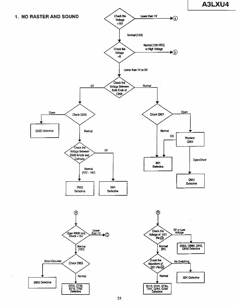
1. NO RASTER AND SOUND
I Normel (15’4’
LowerfhenlVofOV
1 0005 Defective 1 1 Normal
l
ov q7
NOnllal (12V- 14V-J
Short-Circuited
1 A3LXU4
Normal +
OK Replace 0901
cl9oA motl, D915, D916 Defective
1 I201 Defective 1
31
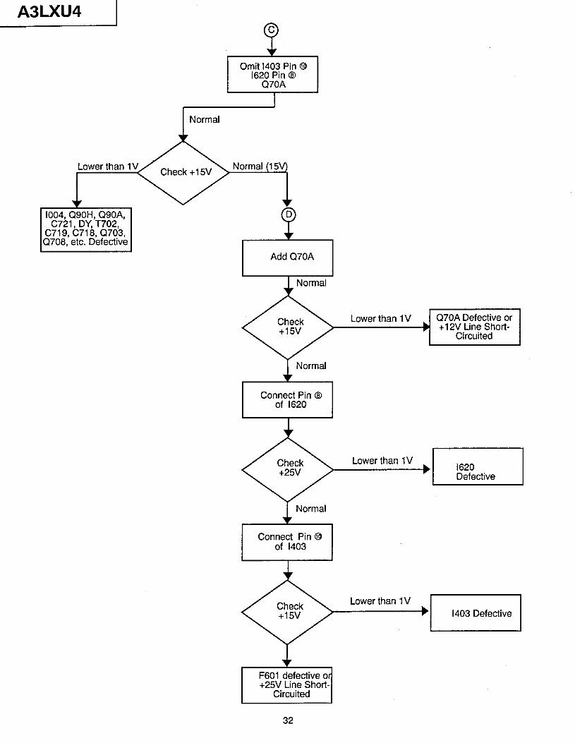
A3LXU4 C
e
Omit 1403 Pin @
‘62~7~~ @
Normal
Lower than 1V
v 1004, Q90H, Q90A,
C721, DY, T702, C719, C718, Q703, Q708, etc. Defective
1 Normal
Connect Pin @ of 1403
Lower than 1 V q7-iL-q
F601 defective o +25V Line Short-
Circuited 1 32
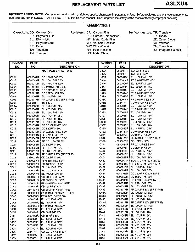
REPLACEMENT PARTS LIST A3LXU4
PRODUCT SAFETY NOTE: Components marked with a Ahave special characters important to safety. Before replacing any of these components, read carefully, the PRODUCT SAFETY NOTICE of this Service Manual. Don’t degrade the safety of the receiver through improper servicing.
ABBREVIATIONS
Capacitors: CD: Ceramic Disc Resistors: CF: Carbon Film PF: Polyester Film CC: Carbon Composition EL: Electrolytic MF: Metal Oxide Film PP: Polypropylene VR: Variable Resistor PR: Paper WW: Wire Wound TA: Tantalum FR: Fuse Resistor TM: Trimmer MG: Metal Glaze
Semiconductors: TR: Transistor DI: Diode ZD: Zener Diode VA Varistor TH: Thermistor IC: Integrated Circuit
SYMBOL PART PART SYMBOL PART PART NO. NO. DESCRIPTION NO. NO. DESCRIPTION
MAIN PWB CAPACITORS C30A 0890071 R CD 56PF-J 5OV c3oc 0890061 R CD 1 OPF- 50V
coo1 0890087R CD lOOOPF-K 5OV C30K 0800015R EL lOUF-M 16V coo2 0800047R EL lOOUF-M 6.3V c314 0880044R PF 0.01 UF-KEB 50V coo3 0800072R EL 470UF-M 6.3V C316 0800009R EL 4.7UF-M 25V coo4 0244141R CD 0.01 UF-KB B 50V c317 0800049R EL lOOUF-M 16V coo5 0890114R CD lOPF-D CH 50 V C318 0800015R EL lOUF-M 16V COO6 0890121 R CD 33PF-J CH 50V c319 0880044R PF 0.01 UF-KEB 50V coo7 0800003R EL l.OUF-M 5OV C31A 0800015R EL lOUF-M 16V COO8 0276717R PP 0.1 UF-J 50V (TF TYP E) c31c 0880044R PF 0.01 UF-KEB 50V COOT 0283127 TM (RED) C31E 0244141 R CD 0.01 UF-KB B 50V coow 0800003R EL l.OUF-M 50V C31 H 0800015R EL lOUF-M 16V co10 0800009R EL 4.7UF-M 25V C31 K 0880044R PF 0.01 UF-KEB 50V co11 0800049R EL lOOUF-M 16V C322 0800049R EL lOOUF-M 16V co12 0800009R EL 4.7UF-M 25V C323 0800015R EL IOUF-M 16V co13 0800015R EL lOUF-M 16V C325 0800015R EL IOUF-M 16V co1 4 0800015R EL lOUF-M 16V C326 0800009R EL 4.7UF-M 25V CO18 0880051 R PP O.O33UF-KEB 50V C327 0800049R EL lOOUF-M 16V co19 0890086R CD 820PF-K 50V c330 0800042R EL 47UF-M 25V COlA 0880048R PP O.O22UF-KEB 50V C332 0244141 R CD 0.01 UF-KB B 50V COlE 0800074N EL 470UF-M 16V c341 0890079R CD 270PF-K 50V co22 0880048R PF O.O22UF-KEB 50V C342 0244171 R CD 0.01 UF-2 F 50V TAPE 5023 0880044R PF 0.01 UF-KEB 5OV c390 0890063R CD 15PF-J 50V 5024 0890085R CD 680PF-K 50V c391 0880044R PF 0.01 UF-KEB 50V 5025 0800009R EL 4.7UF-M 25V c392 0890078R CD 220PF-K 50V S02H 0800015R EL lOUF-M 16V C402 0800015R EL lOUF-M 16V 5031 0276717R PP 0.1 UF-J 50V (TF TYP E) c403 0800015R EL lOUF-M 16V 2032 0890078R CD 220PF-K 50V c404 0800049R EL lOOUF-M 16V 2040 0880057R PF 0.1 UF-KEB 50V c430 0800001 R EL 0.47UF-M 50V (SME) so90 0890087R CD 1 OOOPF-K 5OV c431 0800001 R EL 0.47UF-M 50V (SME) 2091 0800003R EL l.OUF-M 50V C432 0800016R EL lOUF-M 25V ?093 0800005R EL 2.2UF-M 50V c433 0800047R EL lOOUF-M 6.3V 2094 0800047R EL lOOUF-M 6.3V c434 0244105R CD 2200PF-K 50V TAPE 2095 0890121 R CD 33PF-J CH 50V c435 0800059R EL 220UF-M 25V 2096 0890121 R CD 33PF-J CH 50V C436 0244105R CD 2200PF-K 50V TAPE 30Al 0800001R EL 0.47UF-M 50V (SME) c437 0800059R EL 220UF-M 25V ZOA2 0890078R CD 220PF-K 50V C438 0800047R EL lOOUF-M 6.3V ZOA3 0244107R CD 3300PF-K 50V TAPE c439 0276717R PP 0.1 UF-J 50V (TF TYP E) 30A4 0880044R PF 0.01 UF-KEB 50V (CY62) C43A 0800083F EL 1 OOOUF-M 25V 30A6 0880053R PF O.O47UF-KEB 50V c43c 0800082F EL 1 OOOUF-M 16V ZOA7 0800003R EL l.OUF-M 50V C43E 0800041R EL 47UF-M 16V ZOA8 0800015R EL lOUF-M 16V C43H 0278717R PP 0.1 UF-J 50V (-l-F TYP E) XA9 0880044R PF 0.01 UF-KEB 50V C43K 0800082F EL 1 OOOUF-M 16V ZOCl 0800003R EL l.OUF-M 5OV c440 0800059R EL 220UF-M 25V zoc2 0890084R CD 560PF-K 50V c441 0800015R EL lOUF-M 16V x11 0890072R CD 68PF-J 50V c444 0800042R EL 47UF-M 25V 2301 0800003R EL l.OUF-M 50V c445 0800042R EL 47UF-M 25V 2302 0800005R EL 2.2UF-M 50V c450 0800009R EL ‘4.7UF-M 25V ;303 0800015R EL lOUF-M 16V c451 0800009R EL 4.7UF-M 25V ;304 0800003R EL l.OUF-M 50V c453 0800009R EL 4.7UF-M 25V ;305 0244141 R CD 0.01 UF-KB B 50V c454 0800009R EL 4.7UF-M 25V :307 0800005R EL 2.2UF-M 50V c455 0800009R EL 4.7UF-M 25V 2309 0800009R EL 4.7UF-M 25V C456 0800009R EL 4.7UF-M 25V
33
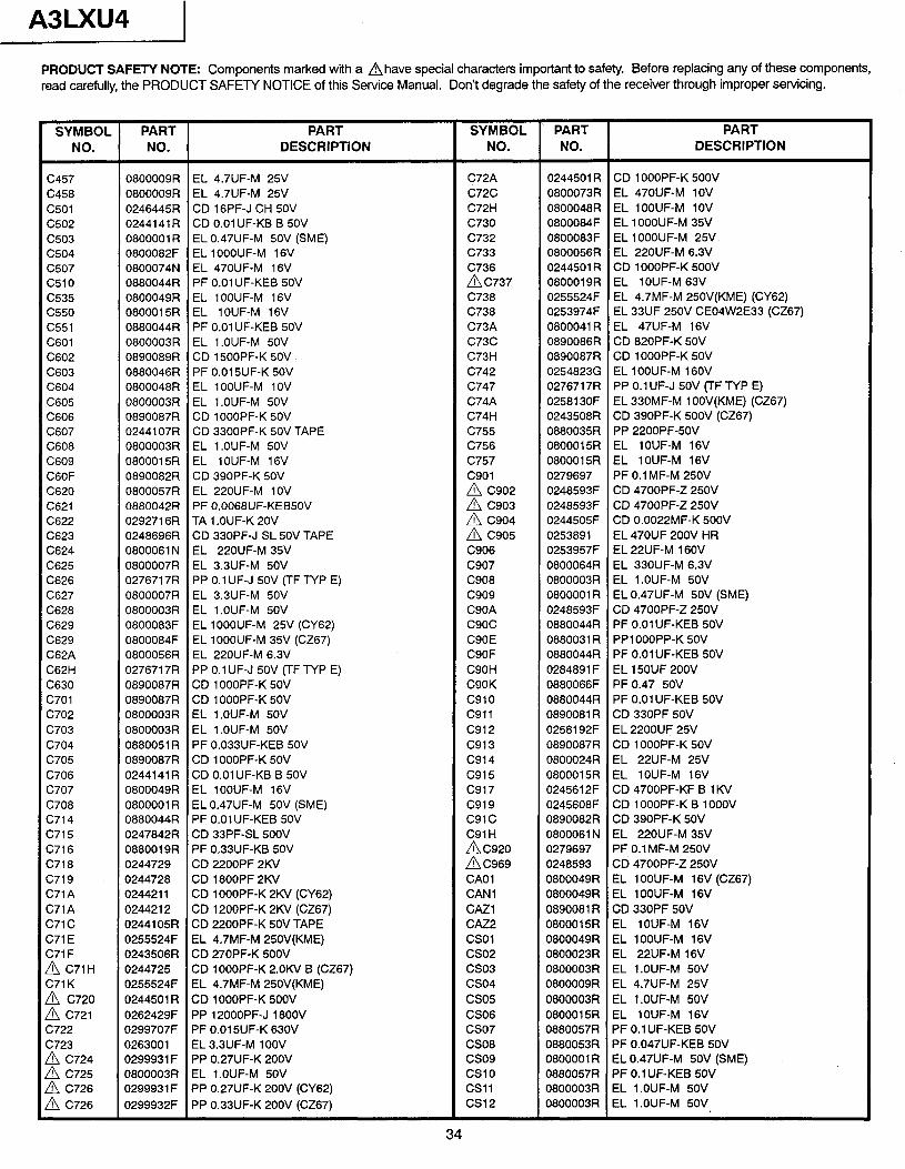
A3LXU4 I PRODUCT SAFETY NOTE: Components marked with a Ahave special characters important to safety. Before replacing any of these components, read carefully, the PRODUCT SAFETY NOTICE of this Service Manual. Don’t degrade the safety of the receiver through improper servicing.
SYMBOL PART NO. NO.
PART DESCRIPTION
SYMBOL PART PART NO. NO. DESCRIPTION
c457 C458 c501 C502 c503 c504 c507 c510 c535 c550 c551 C601 C602 C603 C604 C605 C606 C607 C608 C609 C6OF C620 C621 C622 C623 C624 C625 C626 C627 C628 C629 C629 C62A C62H C630 c701 C702 c703 c704 c705 C706 c707 C708 c714 c715 C716 C718 c719 C71A C71A c71c C71E C71 F A C71H C71 K
2 :;:p C722 C723
0800009R EL 4.7UF-M 25V 0800009R EL 4.7UF-M 25V 0246445R CD 16PF-J CH 50V 0244141R CD 0.01 UF-KB B 50V 0800001R EL 0.47UF-M 50V (SME) 0800082F EL 1 OOOUF-M 16V 0800074N EL 470UF-M 16V 0880044R PF 0.01 UF-KEB 50V 0800049R EL lOOUF-M 16V 0800015R EL lOUF-M 16V 0880044R PF 0.01 UF-KEB 50V 0800003R EL l.OUF-M 50V 0890089R CD 1500PF-K 50V 0880046R PF O.O15UF-K 50V 0800048R EL lOOUF-M 1OV 0800003R EL l.OUF-M 50V 0890087R CD 1 OOOPF-K 50V 0244107R CD 3300PF-K 50V TAPE 0800003R EL l.OUF-M 50V 0800015R EL lOUF-M 16V 0890082R CD 390PF-K 50V 0800057R EL 220UF-M 1OV 0880042R PF O.O068UF-KEB50V 0292716R TA 1 .OUF-K 20V 0248696R CD 33OPF-J SL 50V TAPE 0800061N EL 220UF-M 35V 0800007R EL 3.3UF-M 50V 0276717R PP 0.1 UF-J 50V (TF TYP E) 0800007R EL 3.3UF-M 50V 0800003R EL l.OUF-M 50V 0800083F EL 1 OOOUF-M 25V (CY62) 0800084F EL lOOOUF-M 35V (CZ67) 0800056R EL 220UF-M 6.3V 0276717R PP 0.1 UF-J 50V FF TYP E) 0890087R CD 1 OOOPF-K 50V 0890087R CD 1 OOOPF-K 50V 0800003R EL l.OUF-M 50V 0800003R EL l.OUF-M 50V 0880051 R PF O.O33UF-KEB 50V 0890087R CD lOOOPF-K 50V 0244141 R CD 0.01 UF-KB B 50V 0800049R EL lOOUF-M 16V 0800001R EL 0.47UF-M 50V (SME) 0880044R PF 0.01 UF-KEB 50V 0247842R CD 33PF-SL 500V 0880019R PF 0.33UF-KB 50V 0244729 CD 2200PF 2KV 0244728 CD 18OOPF 2KV 0244211 CD 1 OOOPF-K 2KV (CY62) 0244212 CD 1200PF-K 2KV (CZ67) 0244105R CD 2200PF-K 50V TAPE 0255524F EL 4.7MF-M 250V(KME) 0243506R CD 270PF-K 500V 0244725 CD 1 OOOPF-K 2.OKV B (CZ67) 0255524F EL 4.7MF-M 250V(KME) 0244501 R CD l OOOPF-K 500V 0262429F PP 12OOOPF-J 18OOV 0299707F PF 0.01 SUF-K 630V 0263001 EL 3.3UF-M 1OOV 0299931 F PP 0.27UF-K 200V 0800003R EL l.OUF-M 50V 0299931 F PP 0.27UF-K 200V (CY62) 0299932F PP 0.33UF-K 200V (CZ67)
C72A C72C C72H c730 C732 c733 C736 AC737 C738 C738 C73A c73c C73H C742 c747 C74A C74H c755 C756 c757 c901
2 :z
2 :z C906 c907 C908 c909 C90A c9oc C90E C9OF C90H C90K c910 c911 c912 c913 c914 c915 c917 c919 c91c C91 H A c920 A C969 CA01 CAN1 CAZl cAZ2 CSOl cso2 cso3 cso4 cso5 CS06 cso7 CSO8 cso9 CSlO CSll cs12
0244501 R CD 1 OOOPF-K 500V 0800073R EL 470UF-M 1OV 0800048R EL lOOUF-M 1OV 0800084F EL 1 OOOUF-M 35V 0800083F EL 1 OOOUF-M 25V 0800056R EL 220UF-M 6.3V 0244501 R CD l OOOPF-K 500V 0800019R EL lOUF-M 63V 0255524F EL 4.7MF-M 250V(KME) (CY62) 0253974F EL 33UF 250V CE04W2E33 (CZ67) 0800041 R EL 47UF-M 16V 0890086R CD 820PF-K 50V 0890087R CD 1 OOOPF-K 50V 0254823G EL 1 OOUF-M 16OV 0276717R PP 0.1 UF-J 50V (TF TYP E) 025813OF EL 330MF-M 1 OOV(KME) (CZ67) 0243508R CD 390PF-K 500V (CZ67) 0880035R PP 22OOPF-50V 0800015R EL lOUF-M 16V 0800015R EL lOUF-M 16V 0279697 PF 0.1 MF-M 250V 0248593F CD 47OOPF-Z 250V 0248593F CD 47OOPF-Z 250V 0244505F CD O.O022MF-K 500V 0253891 EL 470UF 200V HR 0253957F EL 22UF-M 16OV 0800064R EL 330UF-M 6.3V 0800003R EL l.OUF-M 50V 0800001 R EL 0.47UF-M 50V (SME) 0248593F CD 47OOPF-Z 250V 0880044R PF 0.01 UF-KEB 50V 0880031 R PPl OOOPP-K 50V 0880044R PF 0.01 UF-KEB 50V 0284891 F EL 15OUF 200V 0880066F PF 0.47 50V 0880044R PF 0.01 UF-KEB 50V 0890081 R CD 330PF 50V 0258192F EL 2200UF 25V 0890087R CD 1 OOOPF-K 50V 0800024R EL 22UF-M 25V 0800015R EL IOUF-M 16V 0245612F CD 4700PF-KF B 1 KV 0245608F CD lOOOPF-K B 1OOOV 0890082R CD 390PF-K 50V 0800061 N EL 220UF-M 35V 0279697 PF 0.1 MF-M 250V 0248593 CD 47OOPF-Z 250V 0800049R EL lOOUF-M 16V (CZ67) 0800049R EL 1 OOUF-M 16V 0890081 R CD 330PF 50V 0800015R EL lOUF-M 16V 0800049R EL lOOUF-M 16V 0800023R EL 22UF-M 16V 0800003R EL l.OUF-M 50V 0800009R EL 4.7UF-M 25V 0800003R EL l.OUF-M 50V 0800015R EL lOUF-M 16V 0880057R PF 0.1 UF-KEB 50V 0880053R PF O.O47UF-KEB 50V 0800001 R EL 0.47UF-M 50V (SME) 0880057R PF 0.1 UF-KEB 50V 0800003R EL l.OUF-M 50V 0800003R EL l.OUF-M 50V
34
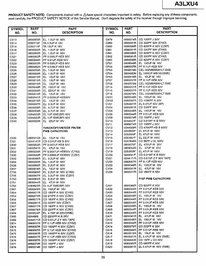
1 A3LXU4
PRODUCT SAFETY NOTE: Components marked with a A have special characters important to safety. Before replacing any of these components, read carefully, the PRODUCT SAFETY NOTICE of this Service Manual. Don’t degrade the safety of the receiver through improper servicing.
SYMBOL PART PART SYMBOL PART PART NO. NO. DESCRIPTION NO. NO. DESCRIPTION
cs13 0800003R EL l.OUF-M 50V C879 0890074R CD lOOPF-J 50V cs14 0292712F TA 3.3UF-K 16V C880 0890081 R CD 330PF 50V (CY62) cs15 0292714F TA 1 OUF-K 16V C880 0890086R CD 820PF-K 50V (CZ67) CS16 0800003R EL l.OUF-M 50V C881 0890081 R CD 330PF 50V (CY62) cs17 0800003R EL l.OUF-M 50V C881 0890086R CD 820PF-K 50V (CZ67) cs21 0880052R PF O.O39UF-KEB 50V C882 0890081 R CD 330PF 50V (CY62) cs22 0880044R PF O.OlUF-KEB 50V C882 0890086R CD 820PF-K 5OV (CZ67) CS23 0880052R PF O.O39UF-KEB 50V CFOl 0800049R EL lOOUF-M 16V CS24 0880052R PF O.O39UF-KEB 50V CF02 0880057R PF 0.1 UF-KEB 5OV CS25 0800003R EL l.OUF-M 50V CF03 0800079N CEL-102M6R3WHLT-SME CS26 0800003R EL l.OUF-M 50V CF04 0800082N EL 1 OOOUF-MB1 GV(SME) CS27 0800015R EL lOUF-M 16V CF05 0800015R EL lOUF-M 16V CS28 0800015R EL lOUF-M 16V CF07 0880057R PF 0.1 UF-KEB 50V cs29 0800015R EL lOUF-M 16V CFO8 0800079N CEL-lOPMGR3WHLT-SME cs30 0800049R EL lOOUF-M 16V CF14 0880057R PF 0.1 UF-KEB 50V cs31 0800058R EL 220UF-M 16V CF15 0880057R PF 0.1 UF-KEB 50V CS32 0800015R EL lOUF-M 16V CF16 0800079N CEL-102M6R3WHLT-SME cs33 0880041 R PF 0,0056UF-KEB50V CM01 0800049R EL lOOUF-M 16V cs34 0800015R EL lOUF-M 16V CM02 0890087R CD 1 OOOPF-K 50V cs35 0800007R EL 3.3UF-M 50V CVOl 0284621 R EL 0.47UF 50V (BP) CS36 0800009R EL 4.7UF-M 25V cvo4 0890081 R CD 330PF 50V cs37 0800009R EL 4.7UF-M 25V cvo5 0800049R EL lOOUF-M 16V CS38 0284623R EL 1 UF-SME(BP) 50V CV06 0880044R PF 0.01 UF-KEB 50V cs39 0284623R EL 1 UF-SME(BP) 50V cvo9 0890074R CD lOOPF-J 50V cs40 0800023R EL 22UF-M 16V CVlO 0244541 F CD 0.01 MF-K B 500V
CVll 0890074R CD lOOPF-J 50V TUNER/CPTNM/SIDE PIN/SM cv12 0244509R CD 4700PF-KB B 500V PWB CAPACITORS cv13 0253959F EL 47UF-M 16OV
cv14 0253959F EL 47UF-M 16OV C320 0800015R EL lOUF-M 16V cv15 0253957F EL 22UF-M 16OV C321 0244141 R CD 0.01 UF-KB B 50V CV16 0247848R CD 56PF-J SL 500V C630 0880053R PF O.O47UF-KEB 50V cv17 0800075F EL 470UF-M 25V C631 0800041 R EL 47UF-M 16V CV18 0800042R EL 47UF-M 25V C632 0880039R PF O.O047UF-KEB50V (CY62) cv19 0253959F EL 47UF-M 16OV C632 0880042R PF O.O068UF-KEB50V (CZ67) cv20 0244541 F CD 0.01 MF-K B 500V C633 0800005R EL 2.2UF-M 50V cv21 0244171 R CD O.OlUF-Z F 50V TAPE C634 0800003R EL l.OUF-M 50V cv22 0880057R PF 0.1 UF-KEB 50V C636 0800005R EL 2.2UF-M 50V CV23 0800049R EL 1 OOUF-M 16V C637 0800018R EL lOUF-M 50V CV24 0800041R EL 47UF-M 16V c735 0800005R EL 2.2UF-M 50V (CY62) CV28 0890077R CD 180PF-K 50V c735 0800007R EL 3.3UF-M 50V (CZ67) c750 0800005R EL 2.2UF-M 50V PINP PWB CAPACITORS c751 0800044R EL 47UF-M 5OV C752 0284623R EL 1 UF-SME(BP) 50V CA01 0890086R CD 820PF-K 50V C851 0800049R EL lOOUF-M 16V CA02 0880044R PF 0.01 UF-KEB 50V C854 0890077R CD 180PF-K 50V (CY62) CA03 0880044R PF 0.01 UF-KEB 50V C854 0890079R CD 270PF-K 50V (CZ67) CA04 0800049R EL lOOUF-M 16V C856 0890077R CD 180PF-K 50V (CY62) CA05 0880044R PF 0.01 UF-KEB 50V C856 0890081 R CD 330PF 50V (CZ67) CA07 0880044R PF 0.01 UF-KEB 50V C857 0890077R CD 180PF-K 50V (CY62) CA08 0800049R EL lOOUF-M 16V C857 0890078R CD 220PF-K 5OV (CZ67) CA09 0880044R PF 0.01 UF-KEB 50V C859 0255524F EL 4.7MF-M 250V(KME) CA1 0 0880044R PF 0.01 UF-KEB 50V C860 0244889 CD 2200PF-K B 2KV CA11 0800041 R EL 47UF-M 16V C866 0244171R CD 0.01 UF-Z F 50V TAPE CA12 0800049R EL lOOUF-M 16V C874 0880057R PF 0.1 UF-KEB 50V (CY62) CA1 3 0880044R PF 0.01 UF-KEB 50V C874 0890087R CD lOOOPF-K 5OV (CZ67) CA14 0890078R CD 220PF-K 5OV C875 0880057R PF 0.1 UF-KEB 50V (CY62) CA1 5 0880044R PF 0.01 UF-KEB 50V C875 0890087R CD lOOOPF-K 50V (CZ67) CA16 0800015R EL ‘lOUF-M 16V C876 0880057R PF 0.1 UF-KEB 50V (CY62) CA1 7 0800001 R EL 0.47UF-M 50V (SME) C876 0890087R CD lOOOPF-K 50V (CZ67) CA18 0246445R CD 16PF-J CH 50V C877 0890074R CD lOOPF-J 50V CA19 0890085R CD 680PF-K 50V C878 0890074R CD lOOPF-J 50V CA20 0800001 R EL 0.47UF-M 5OV (SME)
35
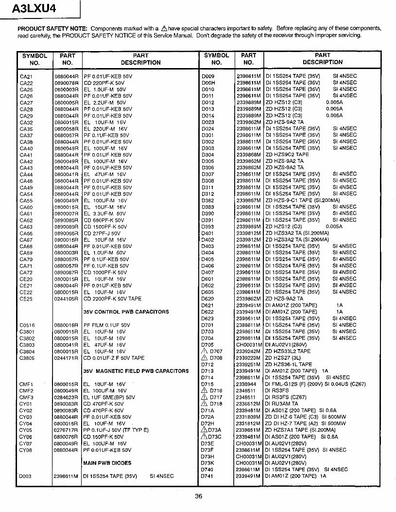
A3LXU4 1
PRODUCT SAFETY NOTE: Components marked with a Ahave special characters important to safety. Before replacing any of these components, read carefully, the PRODUCT SAFETY NOTICE of this Service Manual. Don’t degrade the safety of the receiver through improper servicing.
SYMBOL PART PART SYMBOL PART PART NO. NO. DESCRIPTION NO. NO. DESCRIPTION
CA21 0880044R PF 0.01 UF-KEB 5OV DO09 2398611 M DI 1 SS254 TAPE (35V) SI 4NSEC CA22 0890078R CD 220PF-K 50V DOOH 2398611 M DI 1 SS254 TAPE (35V) SI 4NSEC CA25 0800003R EL l.OUF-M 50V DO10 2398611M DI lSS254 TAPE (35v) SI 4NSEC CA26 0880044R PF 0.01 UF-KEB 50V DO11 2398611 M DI 1 SS254 TAPE (35V) SI 4NSEC CA27 0800005R EL 2.2UF-M 50V DO12 2339889M ZD HZS12 (C3) 0.005A CA28 0880044R PF 0.01 UF-KEB 50V DO13 2339889M ZD HZS12 (C3) 0.005A CA29 0880044R PF 0.01 UF-KEB 50V DO14 2339889M ZD HZS12 (C3) 0.005A CA32 0800015R EL lOUF-M 16V DO23 2339862M ZD HZS-9A2 TA CA35 0800058R EL 220UF-M 16V DO24 2398611M DI lSS254 TAPE (35v) SI 4NSEC CA37 0880057R PF 0.1 UF-KEB 50V D301 2398611 M DI 1 SS254 TAPE (35v) SI 4NSEC CA38 0880044R PF 0.01 UF-KEB 50V D302 2398611 M DI 1 SS254 TAPE (35v) SI 4NSEC CA40 0800049R EL lOOUF-M 16V D303 2398611 M DI 1 SS254 TAPE (35v) SI 4NSEC CA41 0880044R PF 0.01 UF-KEB 50V D304 2339868M ZD HZSSC2 TAPE CA42 0800049R EL lOOUF-M 16V D305 2339862M ZD HZS-9A2 TA CA43 0880044R PF 0.01 UF-KEB 50V D306 2339862M ZD HZSSA2 TA CA44 0800041R EL 47UF-M 16V D307 2398611M DI lSS254 TAPE (35V) SI 4NSEC CA48 0880044R PF 0.01 UF-KEB SOV D308 2398611M DI lSS254 TAPE (359 SI 4NSEC CA49 0880044R PF 0.01 UF-KEB 50V D311 2398611M DI 1 SS254 TAPE (35v) SI 4NSEC CA54 0880044R PF 0.01 UF-KEB 50V D312 2398611 M DI 1 SS254 TAPE (35V) SI 4NSEC CA55 0800049R EL lOOUF-M 16V D382 2339867M ZD HZS-S-Cl TAPE (Sl.200MA) CA60 0800015R EL lOUF-M 16V D383 2398611 M DI 1 SS254 TAPE (35v) SI 4NSEC CA61 0800007R EL 3.3UF-M 50V D390 2398611 M DI 1 SS254 TAPE (35v) SI 4NSEC CA62 0890085R CD 680PF-K 50V D391 2398611 M DI 1 SS254 TAPE (35v) SI 4NSEC CA63 0890089R CD 1 SOOPF-K 50V D393 2339889M ZD HZS12 (C3) 0.005A CA66 0890066R CD 27PF-J 50V D401 2339812M ZD HZS3A2 TA (Sl.200MA) CA67 0800015R EL IOUF-M 16V D402 2339812M ZD HZS3A2 TA (Sl.200MA) CA68 0880044R PF 0.01 UF-KEB 50V D403 2398611 M DI 1 SS254 TAPE (35v) SI 4NSEC CA69 0800003R EL l.OUF-M 50V D404 2398611 M DI 1 SS254 TAPE (35v) SI 4NSEC CA70 0880057R PF 0.1 UF-KEB 50V D405 2398611 M DI 1 SS254 TAPE (35v) SI 4NSEC CA71 0880057R PF 0.1 UF-KEB 50V D406 2398611 M DI 1 SS254 TAPE (35v) SI 4NSEC CA72 0890087R CD 1 OOOPF-K 50V D407 2398611 M DI 1 SS254 TAPE (35V) SI 4NSEC CE20 0800015R EL IOUF-M 16V D601 2398611 M DI 1 SS254 TAPE (35V) SI 4NSEC CE21 0880044R PF 0.01 UF-KEB 5OV D602 2398611 M DI 1 SS254 TAPE (35V) SI 4NSEC CE22 0800015R EL IOUF-M 16V D605 2398611 M DI 1 SS254 TAPE (35v) SI 4NSEC CE25 0244105R CD 2200PF-K 50V TAPE D620 2339862M ZD HZS-SA2 TA
0621 2339491 M DI AMOlZ (200 TAPE) 1A 35V CONTROL PWB CAPACITORS D622 2339491 M DI AMOlZ (200 TAPE) 1A
D623 2398611 M DI 1 SS254 TAPE (35v) SI 4NSEC CO51 6 0880016R PF FILM 0.1 UF 50V D701 2398611 M DI 1 SS254 TAPE (35v) SI 4NSEC C3801 0800015R EL lOUF-M 16V D703 2398611 M DI 1 SS254 TAPE (35v) SI 4NSEC C3802 0800015R EL lOUF-M 16V 0704 2398611 M DI 1 SS254 TAPE (35v) SI 4NSEC C3803 0800041 R EL 47UF-M 16V D705 CH00031 M DI AU02V1(28OV) C3804 0800015R EL 1 OUF-M 16V
2 :::8’ 2339242M ZD HZS33L2 TAPE
C3805 0244171 R CD 0.01 UF-Z F 50V TAPE 2339223M ZD HZS27 (3L) D712 2339251 M ZD HZS36-1 L TAPE
35V MAGNETIC FIELD PWB CAPACITORS D713 2339491M DI AMOlZ (200 TAPE) 1A 0714 2398611 M DI 1 SS254 TAPE (35V) SI 4NSEC
CMFl 0800015R EL lOUF-M 16V 0715 2338944 DI FML-GlPS (F) (2OOv) SI 0.04US (CZ67) CMF2 0800049R EL lOOUF-M 16V
2 :3;; 2348511 DI RSBFS
CMF3 0284623R EL 1 UF-SME(BP) 50V 2348511 DI RSBFS (CZ67) CYOl 0890083R CD 470PF-K 50V A D718 2336612M DI RU3AM TA CYO2 0890083R CD 470PF-K 50V D71A 2339481 M DI ASOlZ (200 TAPE) SI 0.6A CYO3 0880044R PF 0.01 UF-KEB 50V D72A 2331809M ZD DI HZ-6 TAPE (C3) SI 500MW CYO4 0800015R EL lOUF-M 16V D72H 2331812M ZD DI HZ-7 TAPE (A2) SI 500MW CYO5 0276717R PP 0.1 UF-J 50V (TF TYP E)
%: 2339851 M ZD HZS7Al TAPE (Sl.200MA)
CY06 0890076R CD 1 SOPF-K 50V 2339481 M DI AS01 Z (200 TAPE) SI 0.6A CYO7 0800049R EL lOOUF-M 16V D73E CH00031 M DI AU02Vl(28Ov) SYO8 0880044R PF 0.01 UF-KEB 50V D73F 2398611M DI 1 SS254 TAPE (35v) SI 4NSEC
D73H CH00031 M DI AUOPVl(28Ov) MAIN PWB DIODES D73K CH00031 M DI AUOPVl(28Ov)
D740 2398611 M DI 1 SS254 TAPE (35V) SI 4NSEC DO03 2398611 M DI 133254 TAPE (3%) SI 4NSEC D741 2339491 M DI AMOlZ (200 TAPE) 1A
36
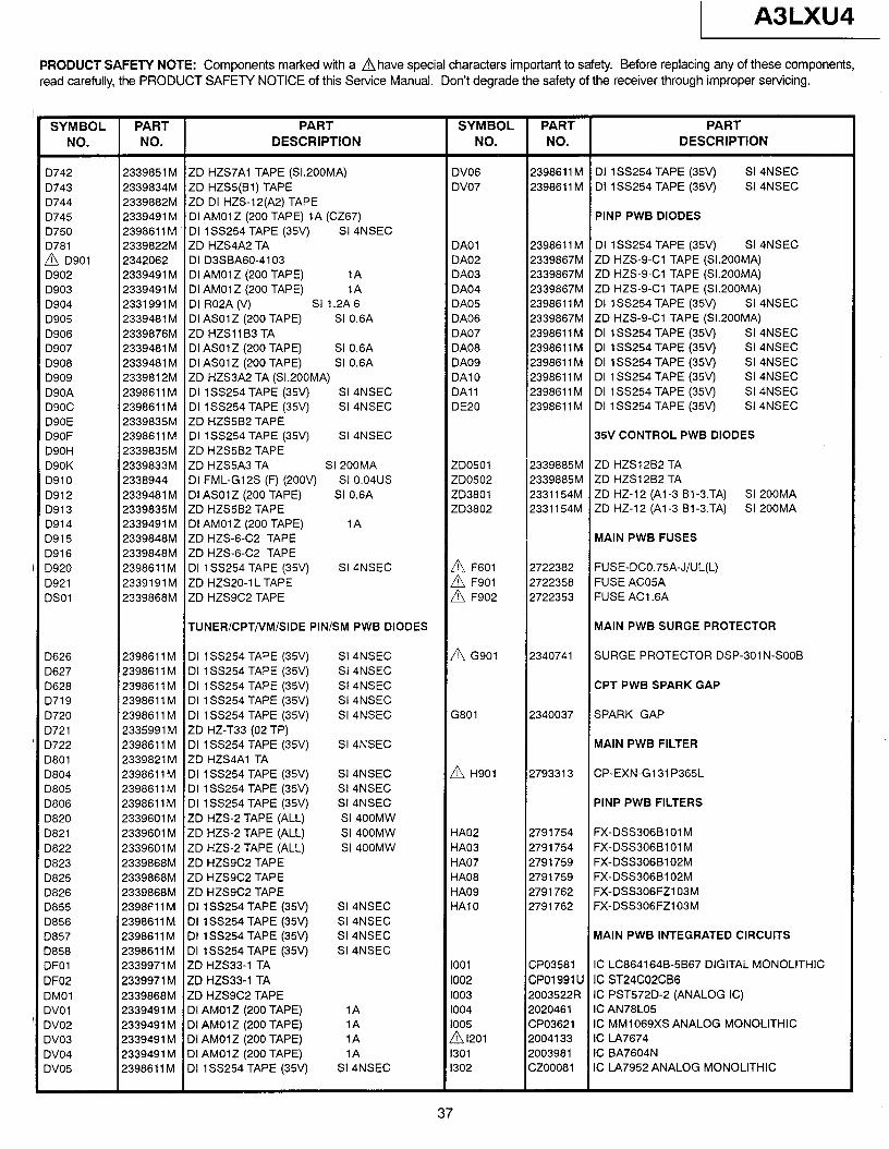
1 A3LXU4
PRODUCT SAFETY NOTE: Components marked with a Ahave special characters important to safety. Before replacing any of these components, read carefully, the PRODUCT SAFETY NOTICE of this Service Manual. Don’t degrade the safety of the receiver through improper servicing.
SYMBOL PART PART SYMBOL PART PART NO. NO. DESCRIPTION NO. NO. DESCRIPTION
D742 2339851 M ZD HZS7Al TAPE (Sl.200MA) DV06 2398611 M DI 1 SS254 TAPE (35V) SI 4NSEC 0743 2339834M ZD HZ%(Bl) TAPE DV07 2398611 M DI 1 SS254 TAPE (35v) SI 4NSEC 0744 2339882M ZD DI HZS-12(A2) TAPE D745 2339491 M DI AMOlZ (200 TAPE) 1A (CZ67) PINP PWB DIODES D750 2398611 M DI 198254 TAPE (35V) SI 4NSEC D781 2339822M ZD HZS4A2 TA DA01 2398611 M DI 1 SS254 TAPE (35v) SI 4NSEC A D901 2342062 DI D3SBA60-4103 DA02 2339867M ZD HZS-g-Cl TAPE (Sl.200MA) D902 2339491 M DI AMOlZ (200 TAPE) 1A DA03 2339867M ZD HZS-g-Cl TAPE (Sl.200MA) D903 2339491 M DI AMOlZ (200 TAPE) 1A DA04 2339867M ZD HZS-9-Cl TAPE (Sl.200MA) D904 2331991M DI R02A (V) SI 1.2A6 DA05 2398611 M DI lSS254 TAPE (35V) SI 4NSEC D905 2339481 M DI ASOlZ (200 TAPE) SI 0.6A DA06 2339867M ZD HZS-g-Cl TAPE (Sl.200MA) D906 2339876M ZD HZSllB3 TA DA07 2398611 M DI 1 SS254 TAPE (35v) SI 4NSEC D907 2339481 M DI ASOlZ (200 TAPE) SI 0.6A DA08 2398611 M DI lSS254 TAPE (35v) SI 4NSEC D908 2339481 M DI ASOlZ (200 TAPE) SI 0.6A DA09 2398611 M DI 1 SS254 TAPE (35v) SI 4NSEC D909 2339812M ZD HZS3A2 TA (Sl.200MA) DA1 0 2398611 M DI 1 SS254 TAPE (35v) SI 4NSEC D90A 2398611 M DI 188254 TAPE (35V) SI 4NSEC DA1 1 2398611 M DI 1 SS254 TAPE (35v) SI 4NSEC D90C 2398611 M DI 1 SS254 TAPE (35V) SI 4NSEC DE20 2398611 M DI 188254 TAPE (35v) SI 4NSEC D90E 2339835M ZD HZS5B2 TAPE D90F 2398611 M DI 1 SS254 TAPE (35V) SI 4NSEC 35V CONTROL PWB DIODES D90H 2339835M ZD HZS5B2 TAPE D90K 2339833M ZD HZS5A3 TA SI 200MA ZOO501 2339885M ZD HZS1282 TA D910 2338944 DI FML-G12S (F) (200V) SI 0.04us ZD0502 2339885M ZD HZS1282 TA D912 2339481 M DI ASOlZ (200 TAPE) SI 0.6A 203801 2331154M ZD HZ-12 (Al-3 Bl-3.TA) SI 200MA D913 2339835M ZD HZS5B2 TAPE ZD3802 2331154M ZD HZ-12 (Al-3 Bl-3.TA) SI 200MA D914 2339491 M DI AMOlZ (200 TAPE) 1A D915 2339848M ZD HZS-6-C2 TAPE MAIN PWB FUSES D916 2339848M ZD HZS-6-C2 TAPE D920 2398611 M DI 188254 TAPE (35V) SI 4NSEC 2722382 FUSE-DC0.75A-J/UL(L) D921 2339191 M ZD HZS20-1 L TAPE 2 ;::: 2722358 FUSE ACOSA DSOl 2339868M ZD HZS9C2 TAPE A F902 2722353 FUSE AC1.6A
TUNER/CPT/VM/SIDE PIN/SM PWB DIODES MAIN PWB SURGE PROTECTOR
D626 2398611M DI lSS254 TAPE (35V) SI 4NSEC A G901 2340741 SURGE PROTECTOR DSP-301 N-SOOB D627 2398611M DI lSS254 TAPE (35V) SI 4NSEC D628 2398611 M DI 1 SS254 TAPE (35V) SI 4NSEC CPT PWB SPARK GAP D719 2398611 M DI 1 SS254 TAPE (35V) SI 4NSEC D720 2398611 M DI 1 SS254 TAPE (35V) SI 4NSEC G801 2340037 SPARK GAP D721 2335991 M ZD HZ-T33 (02 TP) D722 2398611 M DI 1 SS254 TAPE (35V) SI 4NSEC MAIN PWB FILTER D801 2339821M ZD HZS4Al TA D804 2398611 M DI 1 SS254 TAPE (35V) SI 4NSEC A H901 2793313 CP-EXN-G131 P365L D805 2398611 M DI 1 SS254 TAPE (35V) SI 4NSEC D806 2398611 M DI 1 SS254 TAPE (35V) SI 4NSEC PINP PWB FILTERS D820 2339601 M ZD HZS-2 TAPE (ALL) SI 400MW 0821 2339601 M ZD HZS-2 TAPE (ALL) SI 400MW HA02 2791754 FX-DSS306BlOl M D822 2339601 M ZD HZS-2 TAPE (ALL) SI 400MW HA03 2791754 FX-DSS306BlOl M D823 2339868M ZD HZS9C2 TAPE HA07 2791759 FX-DSS306B102M D825 2339868M ZD HZS9C2 TAPE HA08 2791759 FX-DSS306B102M D826 2339868M ZD HZS9C2 TAPE HA09 2791762 FX-DSS306FZ103M D855 2398f 11 M DI 1 SS254 TAPE (35V) SI 4NSEC HA1 0 2791762 FX-DSS306FZl03M D856 2398611 M DI 1 SS254 TAPE (35v) SI 4NSEC D857 2398611 M DI lSS254 TAPE (35V) SI 4NSEC MAIN PWB INTEGRATED CIRCUITS D858 2398611 M DI 1 SS254 TAPE (35V) SI 4NSEC DFOl 2339971 M ZD HZS33-1 TA 1001 GPO3581 IC LC864164B-5867 DIGITAL MONOLITHIC DF02 2339971 M- ZD HZS33-1 TA 1002 CP01991 U IC ST24C02CB6 DMOl 2339868M ZD HZS9C2 TAPE 1003 2003522R IC PST572D-2 (ANALOG IC) DVOl 2339491 M DI AMOlZ (200 TAPE) 1A 1004 2020461 IC AN78L05 DV02 2339491 M DI AMOlZ (200 TAPE) 1A 1005 CP03621 IC MM1069XS ANALOG MONOLITHIC DV03 2339491 M DI AMOlZ (200 TAPE) 1A Al201 2004133 IC LA7674 DV04 2339491 M DI AMOlZ (200 TAPE) 1A 1301 2003981 IC BA7604N DV05 2398611 M DI 1 SS254 TAPE (35V) SI 4NSEC 1302 CZOO081 IC LA7952 ANALOG MONOLITHIC
37
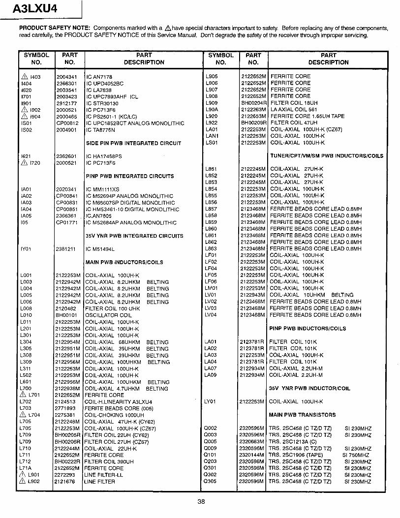
A3LXU4 1 PRODUCT SAFETY NOTE: Components marked with a d have special characters important to safety. Before replacing any of these components, read carefully, the PRODUCT SAFETY NOTICE of this Service Manual. Don’t degrade the safety of the receiver through improper servicing.
SYMBOL PART PART SYMBOL PART PART NO. NO. DESCRIPTION NO. NO. DESCRIPTION
A 1403 2004341 IC AN71 78 L905 2122652M FERRITE CORE 1404 2366301 IC UPD4052BC L906 2122652M FERRITE CORE 1620 2003541 IC LA7838 L907 2122652M FERRITE CORE 1701 2003423 IC UPC7893AHF ICL L908 2122652M FERRITE CORE 1901 2912177 IC STR30130 L909 BH00204R FILTER COIL 18UH
2 I::: 2000521 IC PC71 3F6 L90A 2122263M LAAXIAL COIL 561 2000465 IC PS2501-1 (KC/LC) L920 2122653M FERRITE CORE 1.65UH TAPE
IS01 CPO0812 IC UPC1 852BCT ANALOG MONOLITHIC L922 BH00209R FILTER COIL 47UH IS02 2004901 IC TA8776N IA01 2122253M COIL-AXIAL lOOUH-K (CZ67)
LAN1 2122253M COIL-AXIAL lOOUH-K SIDE PIN PWB INTEGRATED CIRCUIT LSOl 2122253M COIL-AXIAL lOOUH-K
1621 A 1720
IA01 IA02 IA03 IA04 IA05 105
IYOl
-001 -003 -004 -005 -006 -008 -010 -011 -201 -301 -304 -305 -308 -309 -311 -502 -601 -700 !i!x L701 -702 -703 !A L704 -705 -705 .709 .709 .710 -711 .712 .71A 1 L901 ?!J L902
2362601 IC HA17458PS 2000521 IC PC71 3F6
PINP PWB INTEGRATED CIRCUITS
2020341 IC MMllllXS CPO0841 IC M52694P ANALOG MONOLITHIC CPO0831 IC M65607SP DIGITAL MONOLITHIC CPO0851 IC HM53461-10 DIGITAL MONOLITHIC 2366361 IC.AN7805 CPOl771 IC M52684AP ANALOG MONOLITHIC
35V YNR PWB INTEGRATED CIRCUITS
2381211 IC M51494L
MAIN PWB INDUCTORS/COILS
2122253M COIL-AXIAL 1 OOUH-K 2122942M COIL-AXIAL 8.2UHKM BELTING 2122942M COIL-AXIAL 8.2UHKM BELTING 2122942M COIL-AXIAL 8.2UHKM BELTING 2122942M COIL-AXIAL 8.2UHKM BELTING 2120482 FILTER COIL 100 UHK BHOOl 01 OSCILLATOR COIL 2122253M COIL-AXIAL 1 OOUH-K 2122253M COIL-AXIAL 1 OOUH-K 2122253M COIL-AXIAL 1 OOUH-K 2122954M COIL-AXIAL 68UHKM BELTING 2122951 M COIL-AXIAL 39UHKM BELTING 2122951M COIL-AXIAL 39UHKM BELTING 2122956M COIL-AXIAL 1 OOUHKM BELTING 2122253M COIL-AXIAL 1 OOUH-K 2122253M COIL-AXIAL lOOUH-K 2122956M COIL-AXIAL 100UHKM BELTING 2122938M COIL-AXIAL 4.7UHKM BELTING 2122652M FERRITE CORE 2124513 COIL-H.LINEARITY A3LXU4 2771893 FERITE BEADS CORE (005) 2275381 COIL-CHOKING 1OOOUH 2122248M COIL-AXIAL 47UH-K (CY62) 2122253M COIL-AXIAL 1 OOUH-K (CZ67) BH00205R FILTER COIL 22UH (CY62) BH00206R FILTER COIL 27UH (CZ67) 2122244M COIL-AXIAL 22UH-K 2122652M FERRITE CORE BH00222R FILTER COIL 390UH 2122652M FERRITE CORE 2272293 LINE FILTER-LL 2121676 LINE FILTER
L851 L852 L853 L854 L855 L856 L857 L858 L859 L860 L861 L862 L863 LFOl LF02 LF04 LF05 LFO6 LMOl LVOl LVO2 LVO3 LVO4
LAO1 LAO2 LAO3 LAO4 LAO7 IA09
- LYOl
Q002 0003 Q005 Q009 0101 0203 Q301 Q302 Q305
TUNER/CPT/VM/SM PWB INDUCTORS/COILS
2122245M COIL-AXIAL 27UH-K 2122245M COIL-AXIAL 27UH-K 2122245M COIL-AXIAL 27UH-K 2122253M COIL-AXIAL lOOUH-K 2122253M COIL-AXIAL lOOUH-K 2122253M COIL-AXIAL 1 OOUH-K 2123468M FERRITE BEADS CORE LEAD 0.8MH 2123468M FERRITE BEADS CORE LEAD 0.8MH 2123468M FERRITE BEADS CORE LEAD 0.8MH 2123468M FERRITE BEADS CORE LEAD 0.8MH 2123468M FERRITE BEADS CORE LEAD 0.8MH 2123468M FERRITE BEADS CORE LEAD 0.8MH 2123468M FERRITE BEADS CORE LEAD 0.8MH 2122253M COIL-AXIAL lOOUH-K 2122253M COIL-AXIAL lOOUH-K 2122253M COIL-AXIAL lOOUH-K 2122253M COIL-AXIAL 1 OOUH-K 2122253M COIL-AXIAL 1 OOUH-K 2122253M COIL-AXIAL 1 OOUH-K 2122943M COIL-AXIAL 10UHKM BELTING 2123468M FERRITE BEADS CORE LEAD 0.8MH 2123468M FERRITE BEADS CORE LEAD 0.8MH 2123468M FERRITE BEADS CORE LEAD 0.8MH
PINP PWB INDUCTORS/COILS
2123781 R FILTER COIL 101 K 2123781R FILTER COIL 101K 2122253M COIL-AXIAL lOOUH-K 2123781 R FILTER COIL 101 K 2122934M COIL-AXIAL 2.2UH-M 2122934M COIL-AXIAL 2.2UH-M
35V YNR PWB INDUCTOR/COIL
2122253M COIL-AXIAL 1 OOUH-K
MAIN PWB TRANSISTORS
2320596M TRS. 2SC458 (C TZ/D TZ) SI 230MHZ 2320596M TRS. 250458 (C TZ/D TZ) SI 230MHZ 2320663M TRS. 2SC1213A (C) 2320596M TRS. 2SC458 (C TZ/D TZ) SI 230MHZ 2320144M TRS. 2SC1906 (TAPE) SI 750MHZ 2320596M TRS. 2SC458 (C TZ/D TZ) SI 230MHZ 2320596M TRS. 2SC458 (C TZ/D TZ) SI 230MHZ 2320596M TRS. 2SC458 (C TZ/D TZ) SI 230MHZ 2320596M TRS. 2SC458 (C TZ/D TZ) SI 230MHZ
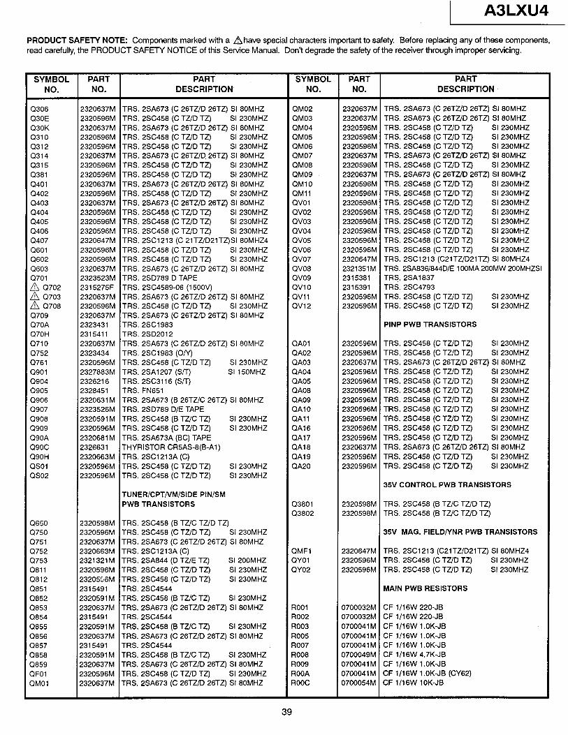
1 A3LXU4
PRODUCT SAFETY NOTE: Components marked with a ahave special characters important to safety. Before replacing any of these components, read carefully, the PRODUCT SAFETY NOTICE of this Service Manual. Don’t degrade the safety of the receiver through improper servicing.
SYMBOL PART NO. NO.
PART DESCRIPTION
SYMBOL PART PART NO. NO. DESCRIPTION
Cl306 Q30E Q30K Q310 Q312 Q314 Q315 Q381 Q401 Q402 Q403 Q404 Q405 Q406 Q407 Q601 Q602 Q603 Q701
2 ::i: A Q708 Q709 Q70A Q70H Q710 Q752 Q761 Q901 Q904 0905 (2906 Q907 Q908 Q909 Q90A Q90C Q90H QSOl QS02
Q650 Q750 Q751 Q752 cl753 Q811 Q812 Cl851 Q852 Cl853 Q854 Q855 Q856 3857 61858 3859 3FOl 3MOl
2320637M TRS. 2SA673 (C 26TZlD 26TZ) SI 80MHZ 2320596M TRS. 2SC458 (C TZ/D TZ) SI 230MHZ 2320637M TRS. 2SA673 (C 26TZ/D 26TZ) St 80MHZ 2320596M TRS. 2SC458 (C TZ/D TZ) SI 230MHZ 2320596M TRS. 2SC458 (C TZID TZ) SI 230MHZ 2320637M TRS. 2SA673 (C 26TZlD. 26TZ) SI 80MHZ 2320596M TRS. 2SC458 (C TZ/D TZ) SI 230MHZ 2320596M TRS. 2SC458 (C TZ/D TZ) SI 230MHZ 2320637M TRS. 2SA673 (C 26TZ/D 26TZ) SI 80MHZ 2320596M TRS. 2SC458 (C TZ/D TZ) St 230MHZ 2320637M TRS. 2SA673 (C 26TZ/D 26TZ) SI 80MHZ 2320596M TRS. 2SC458 (C TZ/D TZ) SI 230MHZ 2320596M TRS. 2SC458 (C TZ/D TZ) SI 230MHZ 2320596M TRS. 2SC458 (C TZ/D TZ) SI 230MHZ 2320647M TRS. 2SC1213 (C 21TZ/D21TZ)SI 80MHZ4 2320596M TRS. 2SC458 (C TZ/D TZ) SI 230MHZ 2320596M TRS. 2SC458 (C TZ/D TZ) SI 230MHZ 2320637M TRS. 2SA673 (C 26TZ/D 26TZ) SI 80MHZ 2323523M TRS. 2SD789 D TAPE 2315275F TRS. 2SC4589-06 (15OOV) 2320637M TRS. 2SA673 (C 26TZ/D 26TZ) SI 80MHZ 2320596M TRS. 2SC458 (C TZ/D TZ) SI 230MHZ 2320637M TRS. 2SA673 (C 26TZ/D 26TZ) SI 80MHZ 2323431 TRS. 2SC1983 2315411 TRS. 2SD2012 2320637M TRS. 2SA673 (C 26TZ/D 26TZ) SI 80MHZ 2323434 TRS. 2SC1983 (Oh’) 2320596M TRS. 2SC458 (C TZ/D TZ) SI 230MHZ 2327883M TRS. 2SA1207 (S/T) SI 150MHZ 2326216 TRS. 2SC3116 (S/T) 2328451 TRS. FN651 2320631 M TRS. 2SA673 (B 26TUC 26TZ) SI 80MHZ 2323526M TRS. 2SD789 D/E TAPE 2320591 M TRS. 2SC458 (B TZ/C TZ) SI 230MHZ 2320596M TRS. 2SC458 (C TZ/D TZ) SI 230MHZ 2320681 M TRS. 2SA673A (BC) TAPE 2326631 THYRISTOR CR5AS-8(B-Al) 2320663M TRS. 2SC1213A (C) 2320596M TRS. 2SC458 (C TZ/D TZ) SI 230MHZ 2320596M TRS. 2SC458 (C TZ/D TZ) SI 230MHZ
TUNER/CPT/VM/SIDE PIN/SM PWB TRANSISTORS
2320598M TRS. 2SC458 (B TZ/C TZ/D TZ) 2320596M TRS. 2SC458 (C TZ/D TZ) SI 230MHZ 2320637M TRS. 2SA673 (C 26TZ/D 26TZ) SI 80MHZ 2320663M TRS. 2SC1213A (C) 2321321 M TRS. 2SA844 (D TZ/E TZ) SI 200MHZ 2320596M TRS. 2SC458 (C TZ/D TZ) SI 230MHZ 2320556M TRS. 2SC458 (C TZ/D TZ) SI 230MHZ 2315491 TRS. 2SC4544 2320591 M TRS. 2SC458 (B Tit/C TZ) SI 230MHZ 2320637M TRS. 2SA673 (C 26TZ/D 26TZ) SI 80MHZ 2315491 TRS. 2SC45.44 2320591 M TRS. 2SC458 (B TZ/C TZ) SI 230MHZ 2320637M TRS. 2SA673 (C 26TZ/D 26TZ) SI 80MHZ 2315491 TRS. 2SC4544 2320591 M TRS. 2SC458 (B TZIC TZ) SI 230MHZ 2320637M TRS. 2SA673 (C 26TZ/D 26TZ) SI 80MHZ 2320596M TRS. 2SC458 (C TZ/D TZ) SI 230MHZ 2320637M TRS. 2SA673 (C 26TUD 26TZ) SI 80MHZ
QM02 QM03 QM04 QM05 QM06 QM07 QM08 QM09 QMlO QMll QVOl QV02 QV03 QV04 QV05 QV06 QV07 QV08 QV09 QVlO QVll QV12
QAOl QA02 QA03 QA04 QA05 QA08 QA09 QAlO QAll QA16 QA17 QA18 QA19 QA20
Q3801 Q3802
QMFl QYOl QY02
ROOl R002 R003 R005 R007 R008 R009 ROOA ROOC
2320637M TRS. 2SA673 (C 26TZ/D 26TZ) SI 80MHZ 2320637M TRS. 2SA673 (C 26TUD 26TZ) SI 80MHZ 2320596M TRS. 2SC458 (C TZ/D TZ) SI 230MHZ 2320596M TRS. 2SC458 (C TZ/D TZ) SI 230MHZ 2320596M TRS. 2SC458 (C TZ/D TZ) SI 230MHZ 2320637M TRS. 2SA673 (C 26TZ/D 26TZ) SI 80MHZ 2320596M TRS. 2SC458 (C TZ/D TZ) SI 230MHZ 2320637M TRS. 2SA673 (C 26TZ/D 26TZ) SI 80MHZ 2320596M TRS. 2SC458 (C TZ/D TZ) SI 230MHZ 2320596M TRS. 2SC458 (C TZID TZ) SI 230MHZ 2320596M TRS. 2SC458 (C TZ/D TZ) SI 230MHZ 2320596M TRS. 2SC458 (C TZ/D TZ) SI 230MHZ 2320596M TRS. 2SC458 (C TZ/D TZ) SI 230MHZ 2320596M TRS. 2SC458 (C TZ/D TZ) SI 230MHZ 2320596M TRS. 2SC458 (C TZ/D TZ) SI 230MHZ 2320596M TRS. 2SC458 (C TZ/D TZ) SI 230MHZ 2320647M TRS. 2SC1213 (C21TZ/D21TZ) SI 80MHZ4 2321351M TRS. 2SA836/844D/E 100MA 200MW 200MHZSI 2315381 TRS. 2SA1837 2315391 TRS. 2SC4793 2320596M TRS. 2SC458 (C TZ/D TZ) SI 230MHZ 2320596M TRS. 2SC458 (C TZ/D TZ) SI 230MHZ
PINP PWB TRANSISTORS
2320596M TRS. 250458 (C TZ/D TZ) SI 230MHZ 2320596M TRS. 2SC458 (C TZ/D TZ) SI 230MHZ 2320637M TRS. 2SA673 (C 26TZ/D 26TZ) SI 80MHZ 2320596M TRS. 2SC458 (C TZ/D TZ) SI 230MHZ 2320596M TRS. 2SC458 (C TZ/D TZ) SI 230MHZ 2320596M TRS. 2SC458 (C TZ/D TZ) SI 230MHZ 2320596M TRS. 2SC458 (C TZ/D TZ) SI 230MHZ 2320596M TRS. 2SC458 (C TZ/D TZ) SI 230MHZ 2320596M TRS. 2SC458 (C TZ/D TZ) SI 230MHZ 2320596M TRS. 2SC458 (C TZ/D TZ) SI 230MHZ 2320596M TRS. 2SC458 (C TZ/D TZ) SI 230MHZ 2320637M TRS. 2SA673 (C 26TZ/D 26TZ) SI 80MHZ 2320596M TRS. 2SC458 (C TZ/D TZ) SI 230MHZ 2320596M TRS. 2SC458 (C TZ/D TZ) SI 230MHZ
35V CONTROL PWB TRANSISTORS
2320598M TRS. 2SC458 (B TZ/C TZ/D TZ) 2320598M TRS. 2SC458 (B TZ/C TZ,lD TZ)
35V MAG. FIELD/YNR PWB TRANSISTORS
2320647M TRS. 2SC1213 (C21TZ/DPlTZ) SI 80MHZ4 2320596M TRS. 2SC458 (C TZ/D TZ) SI 230MHZ 2320596M TRS. 2SC458 (C TUD TZ) SI 230MHZ
MAIN PWB RESISTORS
0700032M CF 1/16W 220-JB 0700032M CF 1/16W 220-JB 0700041M CF 1/16W l.OK-JB 0700041 M CF 1/16W 1 .OK-JB 0700041 M CF l/l 6W 1 .OK-JB 0700049M CF l/l 6W 4.7K-JB 0700041 M CF 1/16W 1 .OK-JB 0700041 M CF 1/16W 1 .OK-JB (CY62) 0700054M CF 1/16W lOK-JB
39
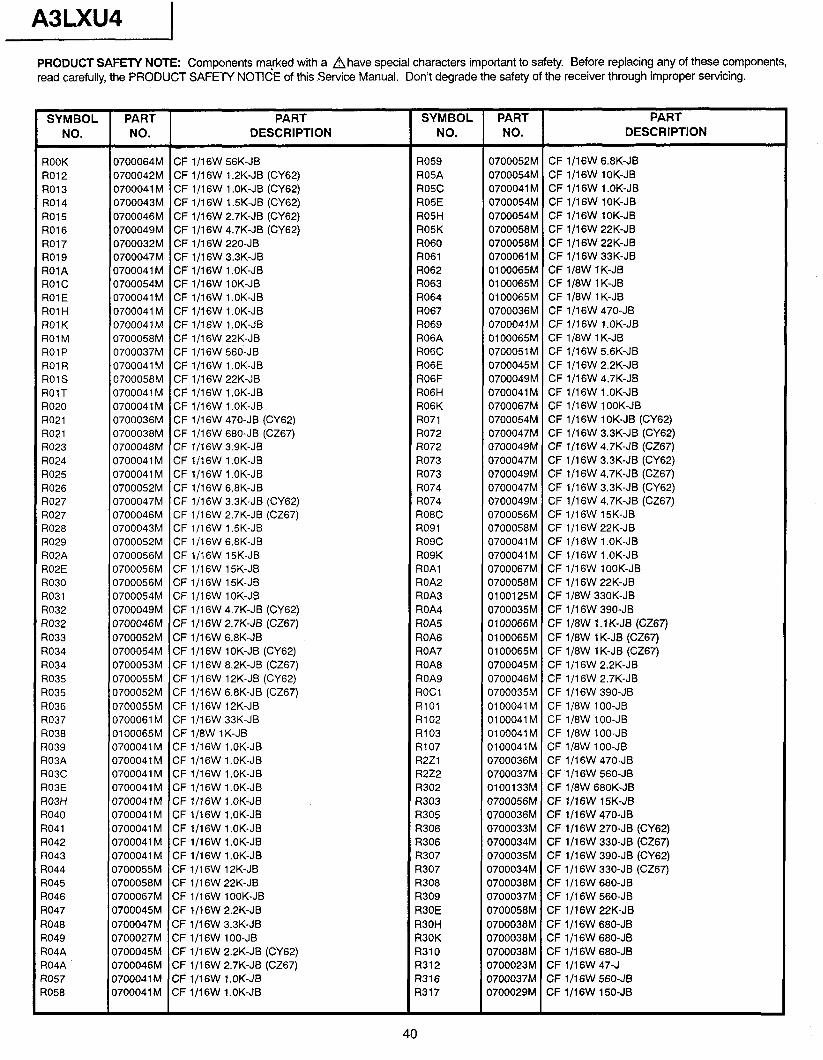
A3LXU4
PRODUCT SAFETY NOTE: Components marked with a Ahave special characters important to safety. Before replacing any of these components, read carefully, the PRODUCT SAFETY NOTICE of this Service Manual. Don’t degrade the safety of the receiver through improper servicing.
SYMBOL PART NO. NO.
PART DESCRIPTION
SYMBOL PART PART NO. NO. DESCRIPTION
ROOK R012 R013 R014 R015 R016 R017 R019 ROlA ROlC ROlE ROlH ROlK ROl M ROlP ROl R ROlS ROlT R020 R021 R021 R023 R024 R025 R026 R027 R027 R028 R029 R02A R02E R030 R031 R032 R032 R033 R034 R034 R035 R035 R036 R037 R038 R039 R03A R03C R03E R03H R040 R041 R042 R043 R044 R045 R046 R047 R048 R049 R04A R04A R057 R058
0700064M CF l/l 6W 56K-JB PI059 0700052M CF l/l 6W 6.8K-JB 0700042M CF 1/16W 1 .PK-JB (CY62) R05A 0700054M CF 1/16W lOK-JB 0700041 M CF l/l 6W 1 .OK-JB (CY62) ROSC 0700041 M CF l/l 6W 1 .OK-JB 0700043M CF l/l 6W 1.5K-JB (CY62) R05E 0700054M CF 1/16W lOK-JB 0700046M CF l/l 6W 2.7K-JB (CY62) R05H 0700054M GF l/l 6W lOK-JB 0700049M CF 1/16W 4.7K-JB (CY62) R05K 0700058M CF 1/16W 22K-JB 0700032M CF 1/16W 220-JB R060 0700058M CF 1/16W 22K-JB 0700047M CF l/l 6W 3.3K-JB R061 0700061 M CF l/l 6W 33K-JB 0700041 M CF l/l 6W 1 .OK-JB R062 0100065M CF 1/8W lK-JB 0700054M CF 1/16W lOK-JB R063 0100065M CF 1/8W 1 K-JB 0700041 M CF l/l 6W 1 .OK-JB R064 0100065M CF 1/8W 1 K-JB 0700041 M CF l/l 6W 1 .OK-JB R067 0700036M CF l/l 6W 470-JB 0700041M CF 1/16W l.OK-JB R069 0700041M CF 1/16W l.OK-JB 0700058M CF l/l 6W 22K-JB R06A 0100065M CF 1/8W 1 K-JB 0700037M CF 1/16W 560-JB R06C 0700051 M CF l/l 6W 5.6K-JB 0700041 M CF 1/16W 1 .OK-JB R06E 0700045M CF 1/16W 2.2K-JB 0700058M CF ll16W 22K-JB R06F 0700049M CF l/l 6W 4.7K-JB 0700041 M CF l/l 6W 1 .OK-JB R06H 0700041 M CF 1/16W 1 .OK-JB 0700041 M CF l/l 6W 1 .OK-JB R06K 0700067M CF 1/16W lOOK-JB 0700036M CF ll16W 470-JB (CY62) R071 0700054M CF 1/16W lOK-JB (CY62) 0700038M CF 1/16W 680-JB (CZ67) R072 0700047M GF l/l 6W 3.3K-JB (CY62) 0700048M CF lf16W 3.9K-JB R072 0700049M CF 1/16W 4.7K-JB (CZ67) 0700041 M CF l/l 6W 1 .OK-JB R073 0700047M CF l/l 6W 3.3K-JB (CY62) 0700041 M CF 1/16W 1 .OK-JB R073 0700049M CF l/l 6W 4.7K-JB (‘X67) 0700052M CF 1/16W 6.8K-JB R074 0700047M CF 1/16W 3.3K-JB (CY62) 0700047M CF 1 J16W 3.3K-JB (CY62) R074 0700049M CF l/l 6W 4.7K-JB (CZ67) 0700046M CF 1/16W 2.7K-JB (CZ67) R08C 0700056M CF ll16W 15K-JB 0700043M CF l/l 6W l.SK-JB R091 0700058M CF l/l 6W 22K-JB 0700052M CF 1/16W 6.8K-JB R09C 0700041M CF 1/16W l.OK-JB 0700056M CF l/1 6W 1 SK-JB R09K 0700041 M CF ll16W 1 .OK-JB 0700056M CF 1/16W 15K-JB ROAl 0700067M CF 1/16W lOOK-JB 0700056M CF 1/16W 15K-JB ROA2 0700058M CF l/l 6W 22K-JB 0700054M CF 1/16W lOK-JB ROA3 0100125M CF 1/8W 33OK-JB 0700049M CF l/l 6W 4.7K-JB (CY62) ROA4 0700035M CF l/l 6W 390-JB 0700046M CF ll16W 2.7K-JB (CZ67) ROA5 0100066M CF ll8W 1.1 K-JB (CZ67) 0700052M CF l/l 6W 6.8K-JB ROA6 0100065M CF 1/8W 1 K-JB (CZ67) 0700054M CF 1/16W lOK-JB (CY62) ROA7 0100065M CF 1/8W lK-JB (CZ67) 0700053M CF l/l 6W 8.2K-JB (CZ67) ROA8 0700045M CF l/l 6W 2.2K-JB 0700055M CF 1/16W 12K-JB (CY62) ROA9 0700046M CF l/l 6W 2.7K-JB 0700052M CF 1/16W 6.8K-JB (CZ67) ROCl 0700035M CF l/l 6W 390-JB 0700055M CF 1/16W 12K-JB RlOl 0100041M CF 1/8W lOO-JB 0700061M CF ll16W 33K-JB R102 0100041M CF 1/8W lOO-JB 0100065M CF ll8W 1 K-JB R103 0100041M CF 1/8W lOO-JB 0700041 M CF l/l 6W 1 .OK-JB R107 0100041M CF ll8W lOO-JB 0700041 M CF l/l 6W 1 .OK-JB R2Zl 0700036M CF l/l 6W 470-JB 0700041 M CF l/l 6W 1 .OK-JB R2Z2 0700037M CF l/l 6W 560-JB 0700041 M CF l/l 6W 1 .OK-JB R302 0100133M CF ll8W 680K-JB 0700041M CF 1/16W l.OK-JB R303 0700056121 CF 1/16W 15K-JB 0700041 M CF 1/16W 1 .OK-JB R305 0700036M CF l/l 6W 470-JB 0700041 M CF l/l 6W 1 .OK-JB R306 0700033M CF l/l 6W 270-JB (CY62) 0700041 M CF l/l 6W 1 .OK-JB R306 0700034M CF l/l 6W 330-JB (CZ67) 0700041 M CF l/l 6W 1 .OK-JB R307 0700035M CF l/l 6W 390-JB (CY62) 0700055M CF ll16W 12K-JB R307 0700034M CF 1/16W 330-JB (CZ67) 0700058M CF l/l 6W 22K-JB R308 0700038M CF 1/16W 680-JB 0700067M CF 1/16W lOOK-JB R309 0700037M CF ll16W 560-JB 0700045M CF 1/16W 2.2K-JB R30E 0700058M CF 1/16W 22K-JB 0700047M CF 1/16W 3.3K-JB R30H 0700038M CF li16W 680-JB 0700027M CF 1/16W lOO-JB R30K 0700038M CF l/lSW 680-JB 0700045M CF l/l 6W 2.2K-JB (CY62) R310 0700038M CF l/l 6W 680-JB 0700046M CF l/l 6W 2.7K-JB (CZ67) R312 0700023M CF l/l 6W 47-J 0700041M CF 1/16W l.OK-JB R316 0700037M CF l/l 6W 560-JB 0700041 M CF l/l 6W 1 .OK-JB R317 0700029M CF 1/16W 150-JB
40
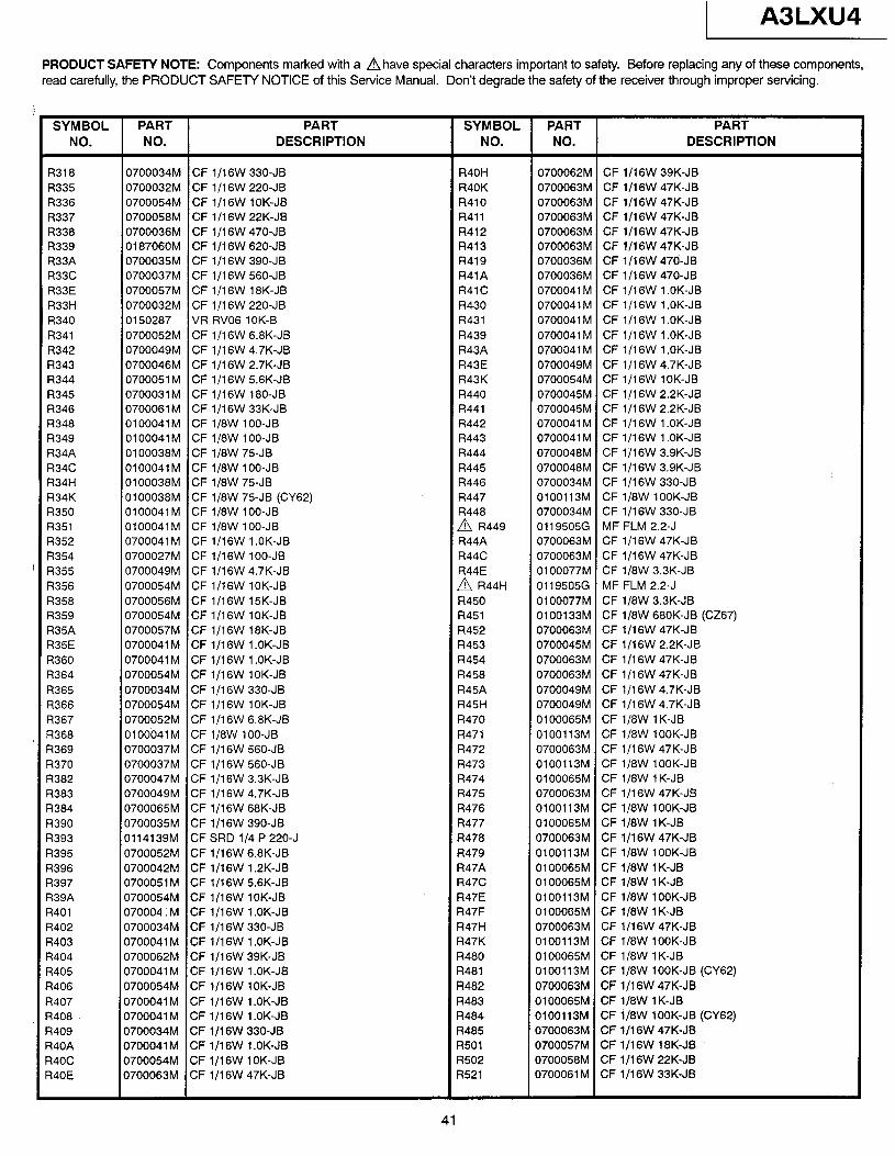
A3LXU4
PRODUCT SAFETY NOTE: Components marked with a Ahave special characters important to safety. Before replacing any of these components, read carefully, the PRODUCT SAFETY NOTICE of this Service Manual. Don’t degrade the safety of the receiver through improper servicing.
SYMBOL NO.
PART NO.
PART DESCRIPTION
SYMBOL PART PART NO. NO. DESCRIPTION
R318 R335 R336 R337 R338 R339 R33A R33C R33E R33H R340 R341 R342 R343 R344 R345 R346 R348 R349 R34A R34C R34H R34K R350 R351 R352 R354 R355 R356 R358 R359 R35A R35E R360 R364 R365 R366 R367 1368 3369 3370 3382 =i383 3384 3390 3393 3395 3396 ?397 ?39A 3401 3402 3403 3404 3405 3406 3407 3408 3409 34OA 34oc 34OE
0700034M CF l/l 6W 330-JB 0700032M CF l/l 6W 220-JB 0700054M CF lIl6W lOK-JB 0700058M CF l/l 6W 22K-JB 0700036M CF l/l 6W 470-JB 018706OM CF l/l 6W 620-JB 0700035M CF l/l 6W 390-JB 0700037M CF l/l 6W 560-JB 0700057M CF 1/16W 18K-JB 0700032M CF l/l 6W 220-JB 0150287 VR RV06 lOK-B 0700052M CF 1IlSW 6.8K-JB 0700049M CF 1116W 4.7K-JB 0700046M CF l/l 6W 2.7K-JB 0700051 M CF 1/16W 5.6K-JB 0700031M CF li16W 180-JB 0700061 M CF l/l 6W 33K-JB 0100041M CF 1/8W lOO-JB 0100041M CF 1/8W lOO-JB 0100038M CF 1/8W 75-JB 0100041M CF 1/8W lOO-JB 01 OOO38M CF 1/8W 75-JB 0100038M CF 1/8W 75JB (CY62) 0100041M CF 1/8W lOO-JB 0100041M CF lJ8W lOO-JB 0700041 M CF 1/16W 1 .OK-JB 0700027M CF 1/16W lOO-JB 0700049M CF l/l 6W 4.7K-JB 0700054M CF 1/16W lOK-JB 0700056M CF 1/16W 15K-JB 0700054M CF l/l 6W IOK-JB 0700057M CF 1/16W 18K-JB 0700041 M CF 1/16W 1 .OK-JB 0700041 M CF l/l 6W 1 .OK-JB 0700054M CF 1/16W lOK-JB 0700034M CF l/l 6W 330-JB 0700054M CF 1/16W lOK-JB 0700052M CF 1/16W 6.8K-JB 0100041M CF 1/8W lOO-JB 0700037M CF l/l 6W 560-JB 0700037M CF l/l 6W 560-JB 0700047M CF ll16W 3.3K-JB 0700049M CF 1IlSW 4.7K-JB 0700065M CF l/l 6W 68K-JB 0700035M CF l/l 6W 390-JB 0114139M CF SRD l/4 P 220-J 0700052M CF l/l 6W 6.8K-JB 0700042M CF l/l 6W 1.2K-JB 0700051 M CF 1/16W 5.6K-JB 0700054M CF 1/16W lOK-JB 070004 : M CF 1/16W 1 .OK-JB 0700034M CF l/l 6W 330-JB 0700041 M CF l/l 6W 1 .OK-JB 0700062M CF 1/16W 39K-JB 0700041 M CF 1/16W 1 .OK-JB 0700054M CF 1/16W lOK-JB 0700041 M CF 1 J16W 1 .OK-JB 0700041 M CF l/l 6W 1 .OK-JB 0700034M CF l/l 6W 330-JB 0700041 M CF l/l 6W 1 .OK-JB 0700054M CF l/l 6W 1 OK-JB 0700063M CF 1/16W 47K-JB
R4OH 0700062M CF l/l 6W 39K-JB R4OK 0700063M CF l/l 6W 47K-JB R410 0700063M CF l/l 6W 47K-JB R411 0700063M CF l/l 6W 47K-JB R412 0700063M CF l/l 6W 47K-JB R413 0700063M CF 1/16W 47K-JB R419 0700036M CF l/l 6W 470-JB R41A 0700036M CF 1 I1 6W 470-JB R41 C 0700041 M CF 1/16W 1 .OK-JB R430 0700041M CF 1/16W l.OK-JB R431 0700041 M CF l/l 6W 1 .OK-JB R439 0700041 M CF 1/16W 1 .OK-JB R43A 0700041 M CF 1/16W 1 .OK-JB R43E 0700049M CF l/l 6W 4.7K-JB R43K 0700054M CF 1/16W lOK-JB R440 0700045M CF l/l 6W 2.2K-JB R441 0700045M CF l/l 6W 2.2K-JB R442 0700041M CF 1/16W l.OK-JB R443 0700041 M CF 1/16W 1 .OK-JB R444 0700048M CF l/l 6W 3.9K-JB R445 0700048M CF l/l 6W 3.9K-JB R446 0700034M CF l/l 6W 330-JB R447 0100113M CF 1/8W lOOK-JB R448 0700034M CF 1/16W 330-JB
A R449 01195050 MF FLM 2.2-J R44A 0700063M CF 1/16W 47K-JB R44C 0700063M CF l/l 6W 47K-JB R44E 0100077M CF 1/8W 3.3K-JB A R44H 01195056 MF FLM 2.2-J R450 0100077M CF 1/8W 3.3K-JB R451 0100133M CF 1/8W 68OK-JB (CZ67) R452 0700063M CF l/l 6W 47K-JB R453 0700045M CF 1/16W 2.2K-JB R454 0700063M CF l/l 6W 47K-JB R458 0700063M CF l/l 6W 47K-JB R45A 0700049M CF l/l 6W 4.7K-JB R45H 0700049M CF l/l 6W 4.7K-JB R470 0100065M CF 1/8W 1 K-JB R471 0100113M CF 1/8W lOOK-JB R472 0700063M CF 1/16W 47K-JB R473 0100113M CF 1/8W lOOK-JB R474 0100065M CF 1/8W 1 K-JB R475 0700063M CF l/l 6W 47K-JB R476 0100113M CF 1/8W lOOK-JB R477 0100065M CF 1/8W 1 K-JB R478 0700063M CF l/l 6W 47K-JB R479 0100113M CF 1/8W lOOK-JB R47A 0100065M CF 1/8W 1 K-JB R47C 0100065M CF 1/8W 1 K-JB R47E 0100113M CF 1/8W lOOK-JB R47F 0100065M CF 1/8W 1 K-JB R47H 0700063M CF l/l 6W 47K-JB R47K 0100113M CF 1/8W lOOK-JB R480 0100065M CF 1/8W 1 K-JB R481 0100113M CF 1/8W lOOK-JB (CY62) R482 0700063M CF l/l 6W 47K-JB R483 0100065M CF lJ8W 1 K-JB R484 0100113M CF 1/8W lOOK-JB (CY62) R485 0700063M CF lJ16W 47K-JB R501 0700057M CF 1/16W 18K-JB R502 0700058M CF 1/16W 22K-JB R521 0700061 M CF ll16W 33K-JB
41
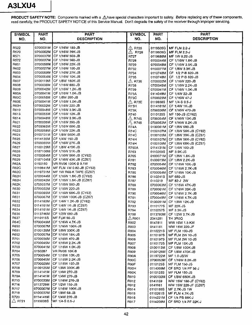
A3LXU4 1 PRODUCT SAFETY NOTE: Components marked with a Ahave special characters important to safety. Before replacing any of these components, read carefully, the PRODUCT SAFETY NOTICE of this Service Manual. Don’t degrade the safety of the receiver through improper servicing.
SYMBOL PART PART SYMBOL PART PART NO. NO. DESCRIPTION NO. NO. DESCRIPTION
R522 0700031M CF lll6W 180-JB A R725 0119505G MF FLM 2.2-J R570 0700062M CF lll6W 39K-JB A R726 0119505G MF FLM 2.2-J R571 0700037M CF l/l 6W 560-JB R727 0119688M MF 1W 0.22-JB R572 0700037M CF 1/16W 560-JB R728 0700044M CF 1/16W 1.8K-JB R601 0700058M CF 1/16W 22K-JB R729 0700048M CF 1/16W 3.9K-JB R602 0700027M CF 1IlSW 1 00-JB R732 0100077M CF 1/8W 3.3K-JB R603 0700059M CF l/l 6W 27K-JB R734 0113748M CF l/2 P-B 820-JB R604 0700054M CF l/l 6W 1 OK-JB R735 0113748M CF l/2 P-B 820-JB R607 0100119M CF 1/8W 180K-JB A R736 0700032M CF ll16W 220-JB R608 0700038M CF l/l 6W 680-JB R738 0700045M CF 1/16W 2.2K-JB R609 0700042M CF l/l 6W 1.2K-JB R739 0700041 M CF l/l 6W 1 .OK-JB R60A 0700041 M CF l/l 6W 1 .OK-JB R73A 0114049M CF 1/4W 22-JB R60C 0100055M CF l/SW 390-JB R73C 0700023M CF 1/16W 47-J R60E 0700041M CF 1/16W l.OK-JB A R73E 01198383 MF 114-S 0.5-J R60H 0700032M CF l/l 6W 220-JB R73H 0114161M CF 1/4W lK-JB R610 0700048M CF l/16W 3.9K-JB R73K 0700036M CF l/l 6W 470-JB R613 0700055M CF 1/16W 12K-JB R740 01101255 MF 150-JS (CY62) R614 0700048M CF l/l 6W 3.9K-JB
2 E- 0700054M CF 1/16W lOK-JB
R621 0700035M CF l/l 6W 390-JB 0700053M CF l/l 6W 8.2K-JB R622 0700065M CF 1/16W 68K-JB R74A 0100061 M CF 1/8W 680-JB R623 0700058M CF 1/16W 22K-JB R74C 0100107M CF 1/8W 56K-JB (CY62) R624 0100131M CF 1/8W 560K-JB R74C 0100103M CF 1/8W 39K-JB (CZ67) R625 0114135M CF 1/4W 150-JB R74H 0100107M CF 1/8W 56K-JB (CY62) R626 0700059M CF l/l 6W 27K-JB R74H 0100109M CF 1/8W 68K-JB (CZ67) R627 0100129M CF 1/8W 470K-JB R750A 0114131M CF 1/4W lOO-JB R628 0187106M CF 1/16W 51K-JB R763 01102599 MF 3.9K-JS R629 0700064M CF 1116W 56K-JB (CY62) R765 0100071 M CF 1/8W 1.8K-JB R629 0187104M CF l/l 6W 43K-JB (CZ67) R781 0100073M CF ll8W 2.2K-JB R62A 0150160 VR RV06 1 OOK-B 0.1 W R782 0700054M CF 1/16W lOK-JB R62C 0119841 M MF FLM 1W 0.82-JB (CY62) R783 0700046M CF l/l 6W 2.7K-JB R62C 0119731 M MF 1 W R68-K TAPE (CZ67) R785 0700054M CF 1/16W lOK-JB R62H 0700044M CF l/l 6W 1.8K-JB (CY62) R786 0110241S MF 680-JS R62H 0700043M CF 1/16W 1.5K-JB (CZ67) R787 0110219 MF 82-J 2W R62K 0700037M CF 1/16W 560-JB R788 0700063M CF l/l 6W 47K-JB R630 0700032M CF l/l 6W 220-JB R789 0700061M CF ll16W 33K-JB R631 0700065M CF l/l 6W 68K-JB (CY62) R790 0700046M CF l/l 6W 2.7K-JB R631 0700067M CF 1/16W lOOK-JB (CZ67) R791 0700049M CF l/l 6W 4.7K-JB R632 0114163M CF 1/4W 1.2K-JB (CY62) R792 0100091M CF 1/8W 12K-JB R632 0114161M CF 1/4W lK-JB (CZ67) R793 0110177S MF 22K-JS R634 0114161M CF 1/4W lK-JB (CZ67) R794 01102578 MF 3.3K-JS R636 0113746M CF 1/2W 680-JB R798 0113760M CF 1/2W 2.7K-JB R637 0110115S MF FLM 56-JS AR901 2341281 TH 3ROQ R64C 0700049M CF l/l 6W 4.7K-JB R902 0147811 WW 15W 1.5KM R650 0700067M CF 1/16W lOOK-JB R903 0141161 WW 15W 220-JF R651 0100125M CF 1/8W 330K-JB R904 0110221S MF FLM lOO-JS R652 0700057M CF 1/16W 18K-JB R905 0110197S MF FLM 2W IO-JS R701 0700036M CF 1/16W 470-JB R906 0110197S MF FLM 2W lo-JS R702 0700045M CF l/l 6W 2.2K-JB R907 0110173S MF FLM lSK-JS ?703 0700041 M CF l/l 6W 1 .OK-JB R908 0100113M CF 1/8W lOOK-JB 1704 0150287 VR RV06 lOK-B R909 0100129M CF 1/8W 470K-JB 3705 0700054M CF 1/16W lOK-JB R90A 0119722M MF 1 .O-JB/W 3706 0700045M CF l/l 6W 2.2K-JB R90C 0700053M CF l/l 6W 8.2K-JB 3707 0700029M CF 1/16W 150-JB R90F 0110125S MF FLM 150-JS 3708 0100125M CF 1/8W 330K-JB R90H 0114059M CF SRD l/4 PF 56-J 3709 0114141M CF 1/4W 270-JB R90K 0110125S MF FLM 150-JS 370A 0114141M CF 1/4W 270-JB R910 0100133M CF 1/8W 680K-JB 3710 0700033M CF 1/16W 270-JB R912 0141159 WW 15W 180-JF (CY62) 3716 0113729M CF 1/2W 150-JB R912 0141161 WW 15W 220-JF (CZ67) 3717 0700067M CF 1/16W lOOK-JB R914 0110155S MF 2.7K-JS 1W 3718 0100037M CF 1/8W 68-JB R915 01102615 MF FLM 4.7K-JS 3720 0114141M CF 1/4W 270-JB !tl R721
R916 0114221M CF l/4 PB 68K-J 01198388 MF 114-S 0.5-J R917 0114209M CF SRD l/4 PF 22K-J
42
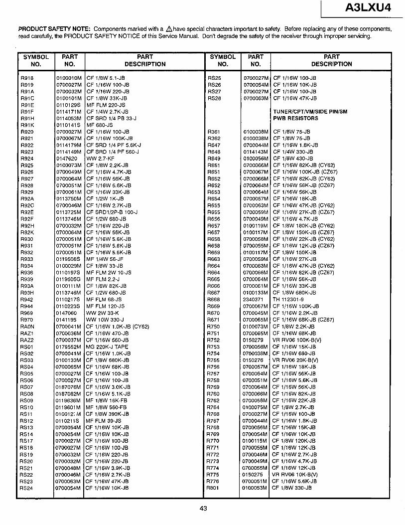
1 A3LXU4
PRODUCT SAFETY NOTE: Components marked with a Ahave special characters important to safety. Before replacing any of these components, read carefully, the PRODUCT SAFETY NOTICE of this Service Manual. Don’t degrade the safety of the receiver through improper servicing.
SYMBOL PART PART SYMBOL PART PART NO. NO. DESCRIPTION NO. NO. DESCRIPTION
R918 OlOOOlOM CF 1/0W 5.1-JB R919 0700027M CF 1/16W loo-JB R91A 0700032M CF l/l 6W 220-JB R91C OlOOlOlM CF 1/8W 33K-JB R91 E 0110129S MF FLM 220-JS R91 F 0114171M CF 1/4W 2.7K-JB R91 H 0114053M CF SRD l/4 PB 33-J R91K 0110141S MF 680-JS R920 0700027M CF 1/16W lOO-JB R921 0700067M CF 1/16W lOOK-JB R922 0114179M CF SRD l/4 PF 5.6K-J R923 0114149M CF SRD l/4 PF 560-J R924 0147620 WW 2.7-KF R925 0100073M CF lJ8W 2.2K-JB R926 0700049M CF 1/16W 4.7K-JB R927 0700064M CF l/l 6W 56K-JB R928 0700051M CF 1/16W 56K-JB R929 0700061 M CF l/l 6W 33K-JB R92A 0113750M CF 1/2W 1 K-JB R92C 0700046M CF l/l 6W 2.7K-JB R92E 0113725M CF SRD1/2P-B 100-J R92F 0113746M CF 1/2W 680-JB R92H 0700032M CF l/l 6W 220-JB R92K 0700064M CF l/l 6W 56K-JB R930 0700051 M CF 1/16W 5.6K-JB R931 0700051M CF 1/16W 5.6K-JB R932 0700051 M CF l/l 6W 5.6K-JB R933 01195088 MF 1/4W 56-JF R934 0100029M CF 1/8W 33-JB R936 0110197S MF FLM 2W lo-JS R939 0119505G MF FLM 2.2-J R93A OlOOlllM CF 1/8W 82K-JB R93H 0113746M CF 1/2W 680-JB R942 0110217S MF FLM 68-JS R944 01102238 MF FLM 120-JS R969 0147060 WW 2W 33-K R970 0141195 WW 1 OW 330-J RAON 0700041 M CF 1/16W 1 .OK-JB (CY62) RAZl 0700036M CF 1IlSW 470-JB RAZ2 0700037M CF l/l 6W 560-JB RSOl 0179552M MG 220K-J TAPE RS02 0700041 M CF 1/16W 1 .OK-JB RS03 0100133M CF 1/8W 680K-JB RS04 0700065M CF 1/16W 68K-JB RS05 0700027M CF 1/16W loo-JB RS06 0700027M CF lll6W lOO-JB RS07 0187076M CF 1/16W 3.0K-JB RS08 0187082M CF 1116W 5.1K-JB RS09 0119636M MF 1/8W 16K-FB RSlO 0119601 M MF ll8W 560-FB RSll 010012; M CF 1/8W 390K-JB RS12 0110211S MF FLM 39-JS RS13 0700054M CF 1/16W lOK-JB RS14 0700054M CF l/l 6W 1 OK-JB RS17 0700027M CF 1/16W lOO-JB RS18 0700027M. CF l/l 6W 1 00-JB RS19 0700032M CF l/l 6W 220-JB us20 0700032M CF 1/16W 220-JB RS21 0700048M CF l/l 6W 3.9K-JB RS22 0700046M CF 1/16W 2.7K-JB RS23 0700063M CF l/l 6W 47K-JB RS24 0700054M CF 1/16W lOK-JB
RS25 RS26 RS27 RS28
R361 R362 R647 R648 R649 R651 R651 R652 R652 R653 R654 R655 R655 R656 R657 R657 R658 R658 R659 R663 R664 R664 R665 R666 R667 R668 R669 R670 R671 R750 R751 R752 R753 R754 R755 R756 R757 R758 R759 R760 R762 R764 R766 R767 R768 R769 R770 R771 R772 R773 R774 R775 R776 R801
0700027M CF 1/16W lOO-JB 0700054M CF 1/16W lOK-JB 0700027M CF l/l 6W 1 00-JB 0700063M CF l/l 6W 47K-JB
TUNER/CPT/VM/SIDE PIN/SM PWB RESISTORS
0100038M CF 1/8W 75-JB 0100038M CF ll8W 75-JB 0700044M CF l/l 6W 1.8K-JB 0114143M CF 1/4W 330-JB 0100056M CF 1/8W 430-JB 0700066M CF l/l 6W 82K-JB (CY62) 0700067M CF l/l 6W 1 OOK-JB (CZ67) 0700066M CF 1/16W 82K-JB (CY62) 0700064M CF l/l 6W 56K-JB (CZ67) 0700064M CF 1/16W 56K-JB 0700057M CF 1/16W 18K-JB 0700063M CF l/l 6W 47K-JB (CY62) 0700059M CF l/l 6W 27K-JB (CZ67) 0700049M CF l/l 6W 4.7K-JB 0100119M CF 1/8W 180K-JB (CY62) 0100117M CF 1/8W 15OK-JB (CZ67) 0700058M CF l/l 6W 22K-JB (CY62) 0700055M CF ll16W lPK-JB (CZ67) 0100117M CF 1/8W 150K-JB 0700059M CF l/l 6W 27K-JB 0700063M CF 1/16W 47K-JB (CY62) 0700066M CF l/l 6W 82K-JB (CZ67) 0700064M CF l/l 6W 56K-JB 0700061M CF 1/16W 33K-JB 0100133M CF ll8W 680K-JB 2340371 TH 112301-g 0700067M CF 1/16W lOOK-JB 0700045M CF l/l 6W 2.2K-JB 0700065M CF l/l 6W 68K-JB (CZ67) 0100073M CF 1/8W 2.2K-JB 0700065M CF l/l 6W 68K-JB 0150279 VR RV06 lOOK-B(V) 0700056M CF 1IlSW 15K-JB 0700038M CF 1/16W 680-JB 0150276 VR RV06 20K-B(V) 0700057M CF 1/16W 18K-JB 0700064M CF 1/16W 56K-JB 0700051M CF 1/16W 5.6K-JB 0700064M CF l/l 6W 56K-JB 0700066M CF l/l 6W 82K-JB 0700058M CF 1/16W 22K-JB 0100075M CF 1/8W 2.7K-JB 0700027M CF 1/16W lOO-JB 0700044M CF 1/16W 1.8K-JB 0700056M CF 1/16W 15K-JB 0700054M CF 1/16W lOK-JB 0100115M CF 1/8W 12OK-JB 0700055M CF 1/16W lPK-JB 0700046M CF l/l 6W 2.7K-JB 0700049M CF l/l 6W 4.7K-JB 0700055M CF 1/16W 12K-JB 0150275 VR RV06 lOK-B(V) 0700051M CF 1/16W 5.6K-JB 0100053M CF 1/8W 330-JB
43
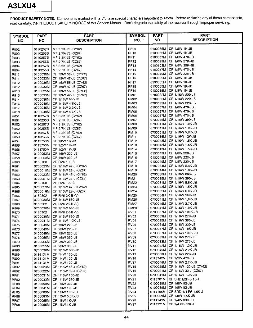
A3LXU4
PRODUCT SAFETY NOTE: Components marked with a Ahave special characters important to safety. Before replacing any of these components, read carefully, the PRODUCT SAFE-l?’ NOTICE of this Service Manual. Don’t degrade the safety of the receiver through improper servicing.
SYMBOL PART NO. NO.
PART DESCRIPTION
SYMBOL PART PART NO. NO. DESCRIPTION
R802 R802 I?803 R803 R804 R804 R811 R811 R812 R812 R813 R813 R814 R816 R817 R818 R851 R851 R852 R852 R853 R853 R854 R855 R856 R857 R858 R860 R861 R861 R863 R863 R864 R865 R865 R866 R867 R868 R869 R870 R871 R874 R875 R876 R877 R878 R879 R880 R886 R889 3890 ?891 ?892 3892 qFO1 qFO2 qFO3 ?FO4 qFO5 ?FO6 ?FO7 3FO8
01102578 MF 3.3K-JS (CY62) 01102559 MF 2.7K-JS (CZ67) 01102578 MF 3.3K-JS (CY62) 01102553 MF 2.7K-JS (CZ67) 01102578 MF 3.3K-JS (CY62) 01102553 MF 2.7K-JS (CZ67) 0100035M CF l/8W 56-JB (CY62) 0100033M CF 1/8W 47-JB (CZ67) 0100035M CF 1/8W 56-JB (CY62) 0100033M CF ll8W 47-JB (CZ67) 0100035M CF 1/8W 56-JB (CY62) 0100033M CF 1/8W 47-JB (CZ67) 0700038M CF l/l 6W 680-JB 0700049M CF 1 J16W 4.7K-JB 0700045M CF 1/16W 2.2K-JB 0700049M CF l/l 6W 4.7K-JB 01102578 MF 3.3K-JS (CY62) 01102558 MF 2.7K-JS (CZ67) 01102573 MF 3.3K-JS (CY62) 01102558 MF 2.7K-JS (CZ67) 01102578 MF 3.3K-JS (CY62) 01102558 MF 2.7K-JS (CZ67) 0113750M CF 1/2W lK-JB 0113750M CF 1/2W lK-JB 0113750M CF 1/2W lK-JB 0100053M CF 1/8W 330-JB 0100053M CF ll8W 330-JB 0150108 VR RV6 100-B 0700023M CF ll16W 47-J (CY62) 0700018M CF l/l 6W 22-J (CZ67) 0700023M CF 1/16W 47-J (CY62) 0700021 M CF 1/16W 33-J (CZ67) 0150108 VR RV6 100-B 0700023M CF 1/16W 47-J (CY62) 0700018M CF l/l 6W 22-J (CZ67) 0150302 VR RV6 2K-B (V) 0700038M CF l/l 6W 680-JB 0150302 VR RV6 2K-B (V) 0700038M CF l/l 6W 680-JB 0 150302 VR RV6 2K-B (V) 0700038M CF l/l 6W 680-JB 0700041 M CF 1/16W 1 .OK-JB 0100049M CF 1/8W 220-JB 0100049M CF 1/8W 220-JB 0100049M CF ‘l/8W 220-JB 0100055M CF ll8W 390-JB 0100055M CF 1/8W 390-JB 0100055M CF 1/8W 390-JB 0700038M CF 1/16W 680-JB 0114131M CF 1/4W lOO-JB 0114131M CF 1/4W loo-JB 0114131M CF 1/4W lOO-JB 0700024M CF l/l 6W 56-J (CY62) 0700022M CF 1/16W 39-J (CZ67) 0700031M CF 1/16W 180-JB 0700033M CF l/l 6W 270-JB 0100053M CF ll8W 330-JB 0100041M CF ll8W lOO-JB 0100089M CF ll8W IOK-JB 0100083M CF ll8W 5.6K-JB 0100065M CF ll8W 1 K-JB 0100065M CF li8W 1 K-JB
RF09 RF10 RF11 RF12 RF13 RF14 RF15 RF16 RF17 RF18 RF19 RMOl RM02 RM03 RM04 RM05 RM06 RM07 RM08 RM09 RMlO RMll RM12 RM13 RM14 RM15 RM16 RM17 RM18 RM19 RM20 RM21 RM22 RM23 RM24 RM25 RM26 RM27 RM28 RVOl RV02 RV04 RV06 RV07 RV08 RV09 RVlO RVll RV12 RV13 RV16 RV17 RVl9 RV19 RV20 RV21 RV22 RV23 RV24 RV25 RV26 RV27
0100065M CF 1/8W 1 K-JB 0100065M CF 1/8W 1 K-JB 0100057M CF 1/8W 470-JB 0100099M CF ll8W 27K-JB 0100103M CF 1/8W 39K-JB 0100057M CF 1/8W 470-JB 0100049M CF ll8W 220-JB 0100065M CF 1/8W 1 K-JB 0100065M CF ll8W 1 K-JB 0100065M CF 1/8W 1 K-JB 0100065M CF 1/8W 1 K-JB 0700032M CF l/l 6W 220-JB 0700032M CF l/l 6W 220-JB 0700032M CF l/l 6W 220-JB 0100057M CF l/8W 470-JB 0100057M CF 1/8W 470-JB 0100057M CF 1/8W 470-JB 0700035M CF l/l 6W 390-JB 0700041 M CF 1/16W 1 .OK-JB 0700041M CF 1/16W l.OK-JB 0700051M CF 1/16W 5.6K-JB 0700055M CF 1/16W lPK-JB 0700043M CF 1/16W 1.5K-JB 0700043M CF l/l 6W 1 .SK-JB 0700043M CF l/l 6W 1.5K-JB 0100049M CF 1/8W 220-JB 0100049M CF ll8W 220-JB 0100049M CF ll8W 220-JB 0187074M CF l/l 6W 2.4K-JB 0700044M CF l/l 6W 1.8K-JB 0700038M CF l/l 6W 680-JB 0700035M CF l/l 6W 390-JB 0700051 M CF 1/16W 5.6K-JB 0700043M CF 1/16W 1 SK-JB 0700052M CF 1/16W 6.8K-JB 0700064M CF 1/16W 56K-JB 0700041 M CF ll16W 1 .OK-JB 0700046M CF l/l 6W 2.7K-JB 0700041 M CF 1/16W 1 .OK-JB 0700067M CF 1/16W lOOK-JB 0700059M CF ll16W 27K-JB 0700035M CF 1/16W 390-JB 0700034M CF 1/16W 330-JB 0700057M CF 1/16W 18K-JB 0700067M CF 1/16W lOOK-JB 0700033M CF l/l 6W 270-JB 0700033M CF 1/16W 270-JB 0700042M CF l/l 6W 1.2K-JB 0700045M CF 1/16W 2.2K-JB 0700058M CF l/l 6W 22K-JB 0113742M CF 1/2W 470-JB 0700046M CF l/l 6W 2.7K-JB 0700028M CF 1/16W 120-JB (CY62) 0700021 M CF l/l 6W 33-J (CZ67) 0700041 M CF 1/16W 1 .OK-JB 0113701M CF SRDl/2P-B 10-J 0100039M CF 1/8W 82-JB 0100039M CF ll8W 82-JB 0114165M CF SRD l/4 PF 1.5K-J 0100069M CF ll8W 1 .SK-JB 0114143M CF li4W 330-JB 0114221M CF l/4 PB 68K-J
44
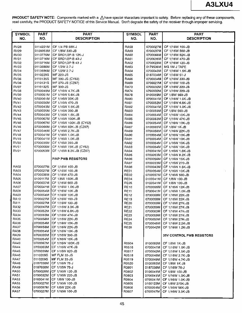
1 A3LXU4
PRODUCT SAFETY NOTE: Components marked with a A have special characters important to safety. Before replacing any of these components, read carefully, the PRODUCT SAFETY NOTICE of this Service Manual. Don’t degrade the safety of the receiver through improper servicing.
SYMBOL PART NO. NO.
PART DESCRIPTION
SYMBOL PART PART NO. NO. DESCRIPTION
RV28 RV29 RV30 RV31 RV32 RV33 RV34 RV35 RV36 RV36 RV37 RV38 RV39 RV40 RV41 RV42 RV43 RV44 RV4.5 RV46 RV46 RV47 RV48 RV49 RV50 1v51 ?V51
qA02 qA03 ?A04 qA05 ?A06 qA07 ?A08 ?A09 qA10 qAl1 ?A32 ?A33 ?A34 qA35 ?A36 ?A37 ?A38 ?A39 qA40 ?A43 ?A44 7A45 7A46 7A47 qA48 IA49 3A50 jA51 IA53 IA55 IA56 IA57
0114221M CF l/4 PB 68K-J 0100053M CF 1/8W 330-JB 0113776M CF SRDl/2P-B 12K-J 0113716M CF SRDlMP-B 43-J 0113716M CF SRD1/2P-B 43-J 0113686M CF 1/2W 2.7-J 0113686M CF 1/2W 2.7-J 01102298 MF 220-JS 0110135S MF 390-JS (CY62) 011013lS MF 270-JS (CZ67) 0110132S MF 300-JS 0700049M CF l/l 6W 4.7K-JB 0700051M CF 1/16W 5.6K-JB 0700061M CF 1/16W 33K-JB 0700036M CF l/l 6W 470-JB 0700043M CF l/l 6W l.SK-JB 0700035M CF 1/16W 390-JB 0700043M CF 1/16W l.SK-JB 0700067M CF 1/16W lOOK-JB 0700067M CF 1/16W lOOK-JB (CY62) 0700066M CF 1/16W 82K-JB (CZ67) 0700046M CF 1/16W 2.7K-JB 0700041M CF 1/16W 1 .OK-JB 0700041 M CF 1/16W 1 .OK-JB 0700035M CF l/l 6W 390.JB 0700056M CF 1/16W 15K-JB (CY62) 0700053M CF 1/16W 8.2K-JB (CZ67)
PINP PWB RESISTORS
0700027M CF 1/16W lOO-JB 0700027M CF 1/16W lOO-JB 0700036M CF lfl6W 470-JB 0100117M CF 1/8W 150K-JB 0700037M CF l/l 6W 560-JB 0700041 M CF 1/16W 1 .OK-JB 0700054M CF 1/16W lOK-JB 0700054M CF 1/16W lOK-JB 0700027M CF 1/16W lOO-JB 0700027M CF 1/16W lOO-JB 0700047M CF 1/16W 3.3K-JB 0700052M CF 1/16W 6.8K-JB 0700063M CF 1 Jl6W 47K-JB 0700058M CF l/l 6W 22K-JB 0700054M CF 1/16W lOK-JB 0700058M CF l/l 6W 22K-JB 0700054M CF 1/16W lOK-JB 0700035M CF 1/16W 390-JB 0700054M CF 1/16W lOK-JB 0700067M CF 1/16W lOOK-JB 0700063M CF 1/16W 47K-JB 0700039M CF l/l 6W 820-JB 0110209S MF FLM 33-JS 0110209S MF FLM 33-JS 0187038M CF 1/16W 75-J 0187038M CF l/l 6W 75-J 0700028M CF 1/16W 120-JB 0700032M CF 1/16W 220-JB 0100041M CF 1/8W lOO-JB 0700027M CF 1/16W lOO-JB 0100097M CF l/8W 22K-JB 0700027M CF 1/16W lOO-JB
RA58 RA59 RA60 RA61 RA62 RA63 RA64 RA65 RA66 RA69 RA73 RA74 RA78 RA80 RA81 RA82 RA83 RA84 RA85 RA86 RA87 RA89 RA90 RA91 RA92 RA93 RA94 RA95 RA96 RA97 RA98 REOl RE02 RE04 RE05 RElO REll RE12 RE13 RE20 RE21 RE22 RE23 RE24 RE25 RE26
R0504 R0516 R0517 R0518 R0519 R0520 R3801 R3802 R3803 R3804 R3805 R3806 R3807
0700027M CF l/l 6W 1 00-JB 0700037M CF l/l 6W 560-JB 0700066M CF l/l 6W 82K-JB 0700036M CF 1/16W 470-JB 0700028M CF 1/16W 120-JB 0179536M MG 1M J TAPE 0700043M CF 1/16W 1.5K-JB 0187034M CF 1/16W 51-J 0700034M CF 1/16W 330-JB 0700027M CF 1/16W lOO-JB 0700032M CF 1/16W 220-JB 0700032M CF l/l 6W 220-JB 0100059M CF 1/8W 560-JB 0700041 M CF 1/16W 1 .OK-JB 0700052M CF 1/16W 6.8K-JB 0700041M CF 1/16W 1 .OK-JB 0100059M CF 1/8W 560-JB 0700054M CF 1/16W lOK-JB 0700063M CF l/lSW 47K-JB 0700054M CF 1/16W lOK-JB 0100065M CF 1/8W 1 K-JB 0700058M CF l/l 6W 22K-JB 0700054M CF 1/16W lOK-JB 0700054M CF lll6W lOK-JB 0700054M CF 1/16W lOK-JB 0700054M CF 1/16W lOK-JB 0700041 M CF lil6W 1 .OK-JB 0700053M CF 1/16W 8.2K-JB 0700056M CF 1/16W 1 SK-JB 0700033M CF l/l 6W 270-JB 0700043M CF l/l 6W 1.5K-JB 0700054M CF 1/16W lOK-JB 0700037M CF l/l 6W 560-JB 0100041M CF 1/8W lOO-JB 010004lM CF 1/8W lOO-JB 0700055M CF 1/16W 12K-JB 0700041 M CF l/l 6W 1 .OK-JB 0700058M CF l/l 6W 22K-JB 0700058M CF l/l 6W 22K-JB 0700059M CF l/l 6W 27K-JB 0700059M CF l/l 6W 27K-JB 0700063M CF 1/16W 47K-JB 0700059M CF l/l 6W 27K-JB 0700059M CF l/l 6W 27K-JB 0700045M CF l/l 6W 2.2K-JB 0700042M CF l/l 6W 1.2K-JB
35V CONTROL PWB RESISTORS
0100065M CF 1/8W 1 K-JB 0700041 M CF l/l 6W 1 .OK-JB 0700043M CF l/l 6W l.SK-JB 0700046M CF l/l 6W 2.7K-JB 0700049M CF 1/16W 4.7K-JB 0100065M CF 1/8W 1 K-JB 0187038M CF l/l 8W 75-J 0100041M CF 1/8W lOO-JB 0700041 M CF 1/16W 1 .OK-JB 0700041 M CF l/l 6W 1 .OK-JB 0100123M CF 1/8W 270K-JB 0700064M CF 1/16W 56K-JB 0700047M CF 1/16W 3.3K-JB
45
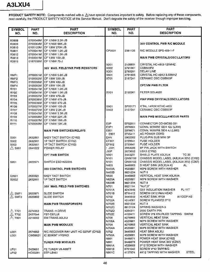
A3LXU4 PRODUCT SAFETY NOTE: Components marked with a Ahave special characters important to safety. Before replacing any of these components, read carefully, the PRODUCT SAFETY NOTICE of this Service Manual. Don’t degrade the safety of the receiver through improper servicing.
SYMBOL PART NO. NO.
PART DESCRIPTION
SYMBOL PART PART NO. NO. DESCRIPTION
R3808 I33809 R3810 R3811 R3812 R3813 R3815
RMFl RMF2 RMF3 RMF4 RYOl RY02 RY03 RY04 RY05 RY06 RY07 RY08 RY09 RYlO RYll
so01 so02 so03 A s901
S851
so501 SO502
A SMFl A SMF2
A T701
2 T;::
UOOl u301
UFO1 UFO2
0700045M CF l/l 6W 2.2K-JB 0700064M CF l/l 6W 56K-JB 35V CONTROL PWB R/C MODULE 0100123M CF 1/8W 270K-JB 0700041 M CF l/l 6W 1 .OK-JB CPO501 2381126 R/C MODULE SPS-409-l -F 0700041 M CF 1/16W 1 .OK-JB 0100041 M CF 1/8W lOO-JB MAIN PWB CRYSTALS/OSCILLATORS 0187038M CF l/l 6W 75-J
x001 2168931 CRYSTAL HC-49/U-120MHZ 35V MAG. FlELD/YNR PWB RESISTORS x002 2791061 CSB503F2
x301 2793281 DELAY LINE 0700051 M CF 1/16W 5.6K-JB x501 2791505 CRYSTAL HC-491 U 3.58MHZ 0100053M CF 1/8W 330-JB x701 2167241 CERAMIC OSC CSB503F 0100056M CF li8W 430-JB 0100093M CF 1/8W 15K-JB CPT/VM PWB FILTER 0700041 M CF l/l 6W 1 .OK-JB 0700041 M CF l/l 6W 1 .OK-JB XV01 2150361 FILTER SDL4620 0100057M CF 1/8W 470-JB 0700036M CF l/l 6W 470-JB PINP PWB CRYSTALS/OSCILLATORS 0700036M CF l/l 6W 470-JB 0700027M CF 1/16W lOO-JB XAOl BP00171 X’TAL 14R3X16THC49/U 0100073M CF l/8W 2.2K-JB XAo2 2167241 CERAMIC OSC CSB503F 0700047M CF l/l 6W 3.3K-JB 0700058M CF 1/16W 22K-JB MAIN PWB MISCELLANEOUS PARTS 0700057M CF 1/16W 18K-JB 0700055M CF 1/16W 12K-JB EOP EF02911 CONNECTOR CO-08CB2-331
E3Pl 2976661 CONN. W/WIRE SEH 12J (L300) MAIN PWB SWITCHES/RELAYS E801 2976671 CONN. W/WIRE SEH 4J (L560)
! E901 2745411 AC POWER CORD 2632851 5KEY TACT SWITCH (CY62) EAN 2902262 PLUG PIN SUB MINI 3P 2632901 1 P TACT SWITCH (CY62) EF901 2720641 FUSE HOLDER 2632901 1 P TACT SWITCH (CY62) EF902 2720641 FUSE HOLDER 2641222 POWER RELAY ! J301 2983095 8P PIN JACK WITH SWITCH
J3OF 2673602 US1 3 (CY62) CPT PWB SWITCH NO01 3443231 SHIELD PLATE A3LXU4 TC-30
NlOl QN00156 CHASSIS MODEL LABEL (A3LXU4 324 (CY62) 2622571 SWITCH ESDl522205 NlOl QN00155 CHASSIS MODEL LABEL (A3LXU4 35v) (CZ67)
N403 3446863 S HEAT SINK (A3u(U4-K-) AL 35V CONTROL PWB SWITCHES N403A 4520881 M3*8 SCREW WITH WASHER
N403B 8821234 NUT-3 2633321 5KEY TACT SWITCH N620 3446862 VERTICAL HEAT SlNKA3LXU4 2632901 1 P TACT SWITCH N620A 4520881 M3*8 SCREW WITH WASHER
N620B 8821234 NUT-3 35V MAG. FIELD PWB SWITCHES N701 8821114 “NUT,3”
N701A 4243445 G51 INSULATION WASHER PL-11T 2620971 SLIDE SWITCH N701 B 8711412 SCREW-3X1 2 PAN HEAD 2620802 SLIDE SWITCH N702 3445542 H.HEAT SINK HY09 All DOP-H2
N702A 4514061 SCREW FLANGED 3*12 MAIN PWB TRANSFORMERS N702B 8821234 NUT-3
N702C 8813124 SPRING WASHER-3 2274353 TRANS.-H.DRIVE N702D 4284311 2000 EARTH PIN 2437094 FBT-C87LUI N702E 4159411 SCREW 3*8 KNURLED TAPPING SWRM 2216002 SW.TRANS.ABLXU N706 4276993 VERTICAL HEAT SINK
N706A 4520881 M3*8 SCREW WITH WASHER MAIN PWB MODULES N70A 4276993 VERTICAL HEAT SINK
N70AA 4520881 M3*8 SCREW WITH WASHER 2574852 R/C RECEIVER RAY UNIT HC-337MF (CY62) N752 3445563 HEAT SINKABLXU CWOO021 IC 331 KNT HYBRID N752A 4520881 M3?8 SCREW WITH WASHER
N901 3446871 POWER HEAT SINK (CY62) TUNER PWB MODULES N901 3446873 POWER HEAT SINK 35V (CZ67)
N901A 4520883 3*12 SCREW WITH WASHER 2429691 FE TUNER V8-A68FT N901B 8781642 SCREW 4*12 TAPPING HC00281 BTF-LB451 N901 C 4137974 4X12 TAPPING WITH WASHER STEEL
46
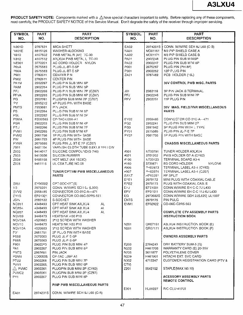
1 A3LXU4
PRODUCT SAFETY NOTE: Components marked with a ahave special characters important to safety. Before replacing any of these components, read carefully, the PRODUCT SAFETY NOTICE of this Service Manual. Don’t degrade the safety of the receiver through improper servicing.
PLUG.JL-BT-E-5P PLUG PIN (PH 8P) PLUG.JL-BT-E-5P 12P PLUG PIN CENTER PIN PCB HOLDER (16L) CENTER PIN PLUG PIN SUB MINI 8P 35V CONTROL PWB MISC. PARTS PLUG PIN SUB MINI 5P PLUG PIN SUB MINI 7P (CZ67) 3P PIN JACK S.TERMINAL PLUG PIN SUB MINI 6P (CZ67) PLUG PIN SUB MINI 7P PLUGPIN SUB MINI 2P (CZ67) 11 P PLUG PIN 4P PLUG PIN WITH BASE
35V MAG. FlELD/YNR MISCELLANEOUS PLUG PIN SUB MINI 5P PLUG PIN SUB MINI 3P CP-TAC-LOSX-Al CONNECTOR CO-01 C-A471 PLUG PIN SUB MINI 4P PLUG PIN SUB MINI 2P PLUG PIN SUB MINI 7P 3P PLUG PIN WITH LTYPE PLUG PIN SUB MINI 6P PLUG PIN JL-F-E 7P 1P PLUG PIN WITH BASE 1 P PLUG PIN WITH BASE 4P PLUG PIN WITH BASE PLUG PIN JL-BT-E 7P (CZ67) CHASSIS MISCELLANEOUS PARTS VARNISH CLOTH TUBE 0.8X1.8 YELLOW SILICONE COMPOUND(G-746) TUNER HOLDER A3LXU4 SILICON RUBBER PWB HOLDER G7-A (CY62) HOT MELT (AX-l 503C) TERMINAL BOARD A3-4 UL CSA TUBE NO.08 BS CORD HOLDER NYLON6
TUNER/CPT/VM PWB MISCELLANEOUS
MINI PLUG WITH COAXIAL CABLE CPT-SOCKET(S) PLUG WITH COAXIAL CABLE CONN. W/WIRE SEH 5J (L300) CONN.W/WIRE EH C-C 7J L430 CONNECTOR CO-01 C-A-471 CONN.W/WIRE EH C-C 11 J-6J L430 CONNECTOR CO-08C-B2R5-561
CPT HEAT SINK A3LXU4 CO-06C-C2R5-560 CPT HEAT SINK A3LXU4 CPT HEAT SINK A3LXU4 COMPLETE CN ASSEMBLY PARTS HEATSINK H30 PlO INSTRUCTION BOOK 3*12 SCREW WITH WASHER HEATSINK H30 PlO 3*12 SCREW WITH WASHER 2P PLUG PIN WITH BASE PLUG JL-F-E-SP OWNERS ASSEMBLY PARTS PLUG JL-F-E-5P PLUG PIN SUB MINI 4P DRY BATTERY SUM-3 (G) PLUG PIN SUB MINI 8P WARRANTY CARD (E) 20-3511
POLYETHLENE COVER HITACHI EXT. SVC CARD
PLUG PIN SUB MINI 7P CUSTOMER REGISTRATION CARD (PTV B PLUG PIN SUB MINI 6P PLUGPIN SUB MINI 2P (CY62) STAPLE(MAX NO.lO) PLUGPIN SUB MINI 2P (CZ67) PLUG PIN SUB MINI 8P ACESSORY ASSEMBLY PARTS
REMOTE CONTROL PINP PWB MISCELLANEOUS PARTS
R/C-CLU-417UI
47
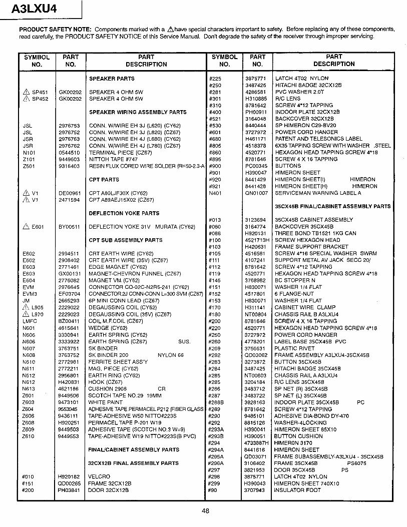
A3LXU4 1
PRODUCT SAFETY NOTE: Components marked with a Ahave special characters important to safety. Before replacing any of these components, read carefully, the PRODUCT SAFETY NOTICE of this Service Manual. Don’t degrade the safety of the receiver through improper servicing.
SYMBOL PART PART SYMBOL PART PART NO. NO. DESCRIPTION NO. NO. DESCRIPTION
SPEAKER PARTS #225 3875771 LATCH 4T02 NYLON #250 3487425 HITACHI BADGE 32CX12B
A SP451 GK00202 SPEAKER 4 OHM 5W #281 A SP452
4286581 PVC WASHER 2.OT GK00202 SPEAKER 4 OHM 5W #301 H310885 R/C LENS
#310 8781642 SCREW 4*12 TAPPING SPEAKER WIRING ASSEMBLY PARTS #400 PH00911 INDOOR PLATE 32CX12B
#521 3164048 BACKCOVER 32CX12B JSL 2976753 CONN. WiWIRE EH 3J (L620) (CY62) #530 8440444 SP HIMERON C29-BV20 JSL 2976752 CONN. W/WIRE EH 3J (L820) (CZ67) #601 3727972 POWER CORD HANGER JSR 2976763 CONN. W/WIRE EH 4J (L680) (CY62) #680 H461171 PATENT AND TELESONICS LABEL JSR 2976762 CONN. W/WIRE EH 4J (L780) (CZ67) #805 4518378 6X35 TAPPING SCREW WITH WASHER STEEL NlOl 0544510 TERMINAL PIECE (CZ67) #860 4520771 HEXAGON HEAD TAPPING SCREW 4*18 2101 9449603 NITTOH TAPE #747 #895 8781646 SCREW 4 X 16 TAPPING z501 9316403 RESIN FLUX CORED WIRE SOLDER (RH50-2.3-A #900 PC00345 BUlTONS
#901 H390047 HIMERON SHEET CPT PARTS #920 8441429 HIMERON SHEET(l) HIMERON
#921 8441428 HIMERON SHEET(H) HIMERON
2;; DE00961 CPT A80LJF30X (CY62) N401 QN01007 SERVICEMAN WARNING LABELA 2471594 CPT A89AEJ15XO2 (CZ67)
35CX45B FINAL/CABINET ASSEMBLY PARTS DEFLECTION YOKE PARTS
#013 A E601
3123694 35CX45B CABINET ASSEMBLY BY0051 1 DEFLECTION YOKE 31V MURATA (CY62) #080 3164774 BACKCOVER 35CX45B
#086 H920131 THREE BOND TB1521 1 KG CAN CPT SUB ASSEMBLY PARTS #lOO 4521713H SCREW HEXAGON HEAD
#103 H420631 FRAME SUPPORT BRACKET E602 2994511 CRT EARTH WIRE (CY62) #105 4516581 SCREW 4*16 SPECIAL WASHER SWRM E602 2908402 CRT EARTH WIRE (35V) (CZ67) #ill 4107241 SUPPORT METALAV JACK SECC 201 E603 2771461 EDGE MAGNET (CY62) #112 8781642 SCREW 4*12 TAPPING E603 GX00131 MAGNET-CHEVRON FUNNEL (CZ67) #119 4520771 HEXAGON HEAD TAPPING SCREW 4*18 E604 2775082 MAGNET VM (CY62) #145 3768982 BCSTOPPERN EVM 2976645 CONNECTOR CO-02C-N2R5-241 (CY62) #151 H830071 WASHER l/4 FLAT EVM3 EF03704 CONNECTOR.2J CONN-CONN L=300 SVM (CZ67) #152 4517801 6 FLANGE-NUT
2665293 6P MINI CONN LEAD (CZ67) 2 L905
#153 H830071 WASHER l/4 FIAT 2229022 DEGAUSSING COIL (CY62) #170 H311141 CABINET WIRE CLAMP
A L970 2229023 DEGAUSSING COIL (35v) (CZ67) #180 NT00804 CHASSIS RAIL B A3LXU4 LMFC 8200411 COIL M.F.COIL (CZ67) #200 8781646 SCREW 4 X 16 TAPPING N601 4615641 WEDGE (CY62) #220 4520771 HEXAGON HEAD TAPPING SCREW 4*18 N606 3330941 EARTH SPRING (CY62) #250 3727972 POWER CORD HANGER N606 3333922 EARTH SPRING (CZ67) sus. #260 4778201 LABEL BASE 35CX45B PVC N607 3763751 SK BINDER #269 3756631 PLASTIC RIVET N608 3763752 SK BINDER 200 NYLON 66 #282 QD03062 FRAME ASSEMBLY A3LXU4-35CX45B N610 2772981 FERRITE SHEET ASS’Y #283 3273872 BUlTON 35CX45B N611 2772211 MAG. PIECE (CY62) #284 3487425 HITACHI BADGE 35CX45B N612 2956801 EARTH RING (CY62) #285 NT00803 CHASSIS RAIL A A3LXU4 N612 H420831 HOOK (CZ67) #285 3204184 R/C LENS 35CX45B N613 4621186 CUSHION 2908 CR #286 3483712 SP NET (R) 35CX45B Z601 9449506 SCOTCH TAPE NO.29 19MM #287 3483722 SP NET (L) 35CX45B 2603 9473101 WHITE PAINT #288B 3828163 INDOOR PLATE 35CX45B PC z604 9553945 ADHESIVE TAPE PERMACEL P212 (FIBER GL4SS #289 8781642 SCREW 4*12 TAPPING Z606 9436111 TAPE-ADHESIVE W50 NITTO#223S #290 9485101 ADHESIVE DIA-BOND DY-470 2608 H920251 PERMACEL TAPE P-201 W19 #292 8815126 WASHER-4LOCKING Z609 9449503 ADHESIVE TAPE (SCOTCH NO.3 W=9) #293A H390041 HIMERON SHEET 85X10 Z610 9449553 TAPE-ADHESIVE W19 NITTO#223S(B PVC) #293B H390051 BUTTON CUSHION
#294 47338871-1 HIMERON 3170 FINAL/CABINET ASSEMBLY PARTS #294A 8441616 HIMERON SHEET
#295A CID03071 FRAME SUBASSEMBLY-ABLXU4 - 35CX45B 32CX12B FINAL ASSEMBLY PARTS #296A 3106402 FRAME 35GX45B PS6075
#297 3821953 DOOR 35CX45B PS YOlO H920182 VELCRO #298 3875771 LATCH 4T02 NYLON Y151 QD00265 FRAME 32CX12B #299 H390043 HIMERON SHEET 740X10 Y200 PH03841 DOOR 32CX12B #90 3707943 INSULATOR FOOT
48
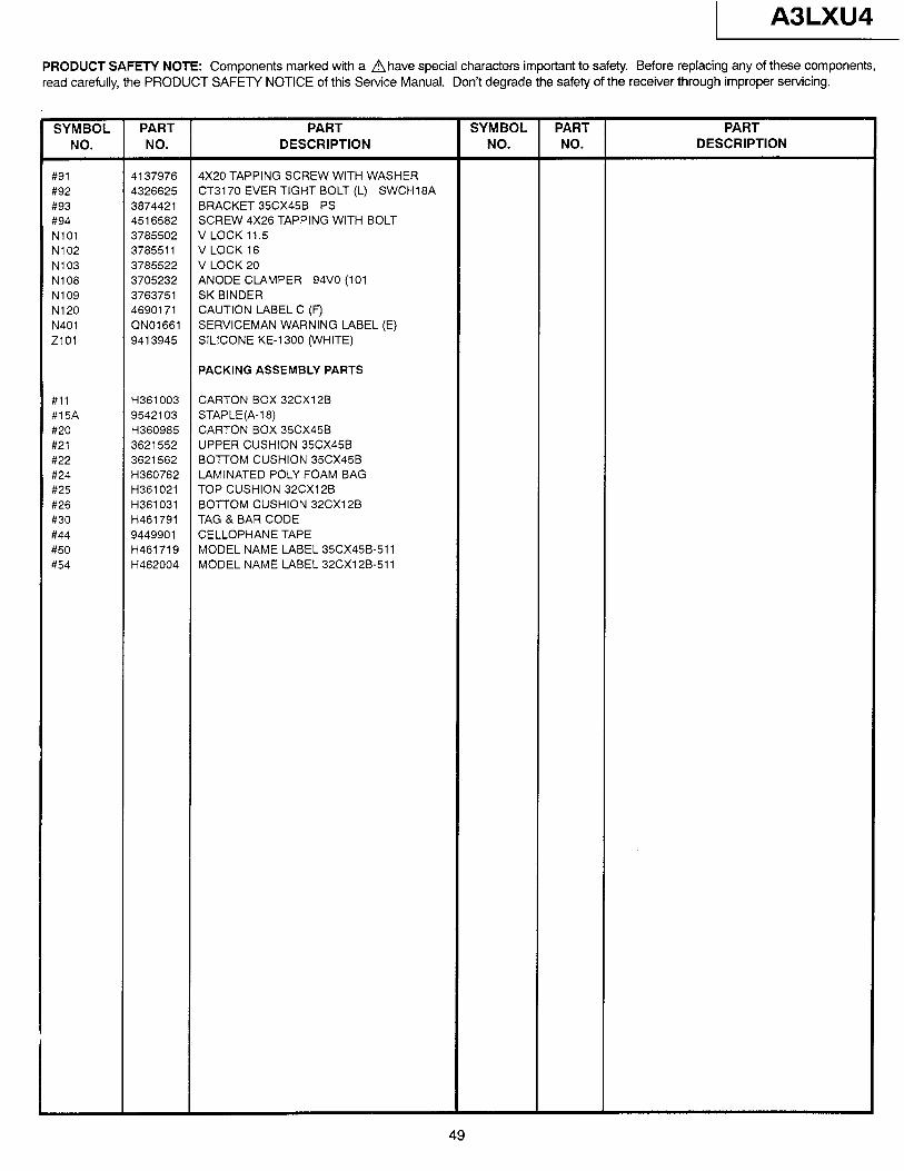
1 A3LXU4
PRODUCT SAFETY NOTE: Components marked with a n have special characters important to safety. Before replacing any of these components, read carefully, the PRODUCT SAFEN NOTICE of this Service Manual. Don’t degrade the safety of the receiver through improper servicing.
SYMBOL PART NO. NO.
PART DESCRIPTION
SYMBOL PART PART NO. NO. DESCRIPTION
iv91 #92 #93 #94 NlOl N102 N103 N108 N109 N120 N401 2101
4137976 4X20 TAPPING SCREW WITH WASHER 4326625 CT3170 EVER TIGHT BOLT (L) SWCH18A 3874421 BRACKET 35CX45B PS 4516582 SCREW 4X26 TAPPING WITH BOLT 3785502 V LOCK 11.5 3785511 VLOCK16 3785522 V LOCK 20 3705232 ANODE CLAMPER 94V0 (101 3763751 SK BINDER 4690171 CAUTION LABEL C (F) QN01661 SERVICEMAN WARNING LABEL (E) 9413945 SILICONE KE-1300 (WHITE)
PACKING ASSEMBLY PARTS
#ll #15A #20 #21 #22 #24 #25 #26 #30 #44 #50 #54
H361003 CARTON BOX 32CX12B 9542103 STAPLE(A-18) H360985 CARTON BOX 35CX45B 3621552 UPPER CUSHION 35CX45B 3621562 BO-ITOM CUSHION 35CX45B H360762 LAMINATED POLY FOAM BAG H361021 TOP CUSHION 32CX12B H361031 BOTTOM CUSHION 32CX12B H461791 TAG & BAR CODE 9449901 CELLOPHANE TAPE H461719 MODEL NAME LABEL 35CX45B-511 H462004 MODEL NAME LABEL 32CX12B-511
49

A3LXU4 I
NOTES
50

A3LXU4
NOTES
51

A3LXU4
NOTES
52