practical color opponency
TRANSCRIPT
Practical Color Opponency
Petr Talla([email protected])
September 28, 2014
Abstract
A big role in the image processing plays the color system in which the image is coded. Thedifferent color systems cause different results using the same computer vision algorithm. This articledescribes simple opponent system based on RGB transformation and named ReGBe here. Even thetransformation is simple, the resulting color system has properties comparable with the other ones.The comparison is done with Ballard, YUV, Otha, Lambert and Hurwich opponent color systems.The additional advance of ReGBe is the compatibility with RGB color system which causes ease of itsunderstanding and interpretation.
Keywords: color system, opponent color system, computer vision, segmentation, rgb.
1 Introduction
If you have an algorithm which uses the color dis-tance calculation then the results can be signifi-cantly enhanced by the used color system. This isshown in [Busin 08]. There is a lot of color sys-tems which can be used for substitution [Busin 08],[Roberts 98].
The most of the current image-processing appli-cations still live in grayscale word. Even the imageis taken in color, many times the first operation isthe translation of the image in grayscale1. Thereare even whole computer vision books with zerooccurrence of the word “color”2.
Probably the first attempts to use color informa-tion are mostly combining the r, g, b color channels.This makes some advantage, but the r, g, b intensi-ties are highly correlated, so the advance is slight.
Most of the attempts to use colors in the imageprocessing are probably hsl and related color sys-tems. Hsl is primarily color description system andit is not suited for recognition tasks.
1Simple Google surwey: “cvLoadImage” - 72k of the re-sults, “cvLoadImage + CV BGR2GRAY” - 24k. And theremust be a lot of images already supposed to be in gray.
2Color has typically special chapter in most of the cur-rent computer vision books, although typically it is poorlyconnected to the other chapters.
The opponent color systems are the last and themost efficient approach. They are even evolution-ary selected by the biological systems image pro-cessing. The opponency has a lot of implementa-tions and the most used are the biologically inspiredvariations.
This article proves that any opponent system canbe successfully replaced for the image processingwith highly simplified opponent color system with-out quality losses. In this article is this color systemnamed by its components ReGBe.
2 Approach to Display Re-sults
Grayscale images for each separate color channelare typically used for displaying the effect of thecolor system. This is illustrated in the table 2.
In this article is used another approach for dis-playing the three channel color systems. It usesthe fact, that every vision specialist unfailingly in-terprets the RGB components intensities in images.Even RGB is described as unintuitive, the years ofpractice do another effect. We are the championsin RGB images understanding. So if three valuesare displayed as RGB images, one can easily in-
1
Practical Color Opponency P. Talla
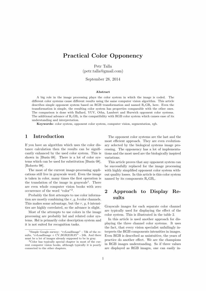
terpret the partial components. The main reasonof such displaying is the ability of direct compari-son. While by eye comparison of triplet images itis impossible, it is easy with images displayed usingRGB mapping.
In this approach the component which representsintensity is mapped in green3. The other two com-ponents are mapped in blue and red RGB compo-nents by its congeniality with blue and red.
Take as an example the XYZ color transforma-tion. XYZ are imaginary coordinates and there isno way how to display them realistically. But wecan use the following RGB mapping : the intensitychannel is Y, so it is mapped in green. Z is mappedin red and X in blue. This is symbolically expressedas:
ZYX
=̂
rgb
(1)
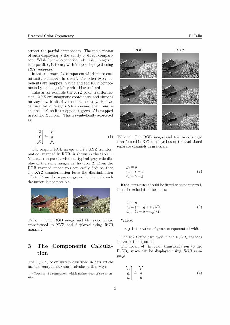
The original RGB image and its XYZ transfor-mation, mapped in RGB, is shown in the table 1.You can compare it with the typical grayscale dis-play of the same images in the table 2. From theRGB mapped image you can easily deduce, thatthe XYZ transformation loses the discriminationeffect. From the separate grayscale channels suchdeduction is not possible.
Table 1: The RGB image and the same imagetransformed in XYZ and displayed using RGBmapping.
3 The Components Calcula-tion
The ReGBe color system described in this articlehas the component values calculated this way:
3Green is the component which makes most of the inten-sity.
RGB XYZ
Table 2: The RGB image and the same imagetransformed in XYZ displayed using the traditionalseparate channels in grayscale.
ge = gre = r − gbe = b− g
(2)
If the intensities should be fitted to some interval,then the calculation becomes:
ge = gre = (r − g + wg)/2be = (b− g + wg)/2
(3)
Where:
wg: is the value of green component of white
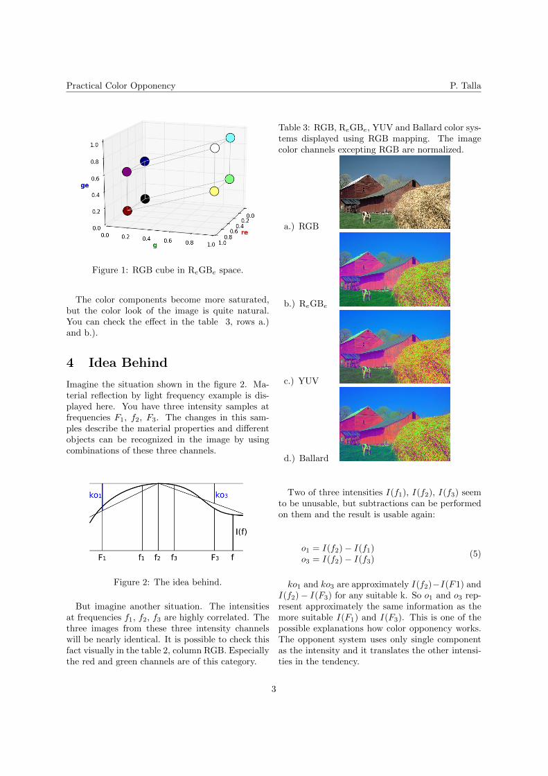
The RGB cube displayed in the ReGBe space isshown in the figure 1:
The result of the color transformation to theReGBe space can be displayed using RGB map-ping :
regebe
=̂
rgb
(4)
2
Practical Color Opponency P. Talla
Figure 1: RGB cube in ReGBe space.
The color components become more saturated,but the color look of the image is quite natural.You can check the effect in the table 3, rows a.)and b.).
4 Idea Behind
Imagine the situation shown in the figure 2. Ma-terial reflection by light frequency example is dis-played here. You have three intensity samples atfrequencies F1, f2, F3. The changes in this sam-ples describe the material properties and differentobjects can be recognized in the image by usingcombinations of these three channels.
Figure 2: The idea behind.
But imagine another situation. The intensitiesat frequencies f1, f2, f3 are highly correlated. Thethree images from these three intensity channelswill be nearly identical. It is possible to check thisfact visually in the table 2, column RGB. Especiallythe red and green channels are of this category.
Table 3: RGB, ReGBe, YUV and Ballard color sys-tems displayed using RGB mapping. The imagecolor channels excepting RGB are normalized.
a.) RGB
b.) ReGBe
c.) YUV
d.) Ballard
Two of three intensities I(f1), I(f2), I(f3) seemto be unusable, but subtractions can be performedon them and the result is usable again:
o1 = I(f2)− I(f1)o3 = I(f2)− I(f3)
(5)
ko1 and ko3 are approximately I(f2)−I(F1) andI(f2)− I(F3) for any suitable k. So o1 and o3 rep-resent approximately the same information as themore suitable I(F1) and I(F3). This is one of thepossible explanations how color opponency works.The opponent system uses only single componentas the intensity and it translates the other intensi-ties in the tendency.
3
Practical Color Opponency P. Talla
4.1 ReGBe
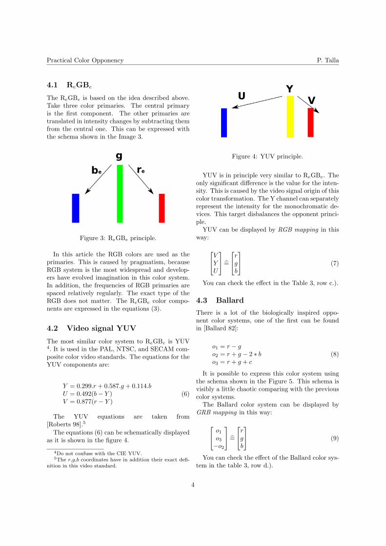
The ReGBe is based on the idea described above.Take three color primaries. The central primaryis the first component. The other primaries aretranslated in intensity changes by subtracting themfrom the central one. This can be expressed withthe schema shown in the Image 3.
Figure 3: ReGBe principle.
In this article the RGB colors are used as theprimaries. This is caused by pragmatism, becauseRGB system is the most widespread and develop-ers have evolved imagination in this color system.In addition, the frequencies of RGB primaries arespaced relatively regularly. The exact type of theRGB does not matter. The ReGBe color compo-nents are expressed in the equations (3).
4.2 Video signal YUV
The most similar color system to ReGBe is YUV4. It is used in the PAL, NTSC, and SECAM com-posite color video standards. The equations for theYUV components are:
Y = 0.299.r + 0.587.g + 0.114.bU = 0.492(b− Y )V = 0.877(r − Y )
(6)
The YUV equations are taken from[Roberts 98].5
The equations (6) can be schematically displayedas it is shown in the figure 4.
4Do not confuse with the CIE YUV.5The r,g,b coordinates have in addition their exact defi-
nition in this video standard.
Figure 4: YUV principle.
YUV is in principle very similar to ReGBe. Theonly significant difference is the value for the inten-sity. This is caused by the video signal origin of thiscolor transformation. The Y channel can separatelyrepresent the intensity for the monochromatic de-vices. This target disbalances the opponent princi-ple.
YUV can be displayed by RGB mapping in thisway:
VYU
=̂
rgb
(7)
You can check the effect in the Table 3, row c.).
4.3 Ballard
There is a lot of the biologically inspired oppo-nent color systems, one of the first can be foundin [Ballard 82]:
o1 = r − go2 = r + g − 2 ∗ bo3 = r + g + c
(8)
It is possible to express this color system usingthe schema shown in the Figure 5. This schema isvisibly a little chaotic comparing with the previouscolor systems.
The Ballard color system can be displayed byGRB mapping in this way:
o1o3−o2
=̂
rgb
(9)
You can check the effect of the Ballard color sys-tem in the table 3, row d.).
4
Practical Color Opponency P. Talla
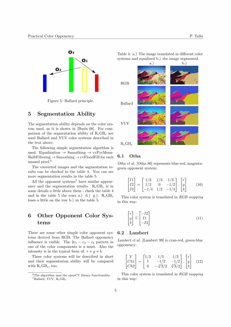
Figure 5: Ballard principle.
5 Segmentation Ability
The segmentation ability depends on the color sys-tem used, as it is shown in [Busin 08]. For com-parison of the segmentation ability of ReGBe areused Ballard and YUV color systems described inthe text above.
The following simple segmentation algorithm isused: Equalization → Smoothing → cvPyrMean-ShiftFiltering→ Smoothing→ cvFloodFill for eachunused pixel.6
The converted images and the segmentation re-sults can be checked in the table 4. You can seemore segmentation results in the table 5.
All the opponent systems7 have similar appear-ance and the segmentation results. ReGBe is insome details a little above them - check the table 4and in the table 5 the rows a.) d.) g.). ReGBe
loses a little on the row b.) in the table 5.
6 Other Opponent Color Sys-tems
There are some other simple color opponent sys-tems derived from RGB. The Ballard opponencyinfluence is visible. The 2c1 − c2 − c3 pattern inone of the color components is a must. Also theintensity is in the typical form of: r + g + b.
These color systems will be described in shortand their segmentation ability will be comparedwith ReGBe, too.
6The algorithm uses the openCV library functionality.7Ballard, YUV, ReGBe
Table 4: a.) The image translated in different colorsystems and equalized b.) the image segmented.
a.) b.)
RGB
Ballard
YUV
ReGBe
6.1 Otha
Otha et al. [Otha 80] represents blue-red, magenta-green opponent system:
I1I2I3
=
1/3 1/3 1/31/2 0 −1/2−1/4 1/2 −1/4
.
rgb
(10)
This color system is translated in RGB mappingin this way:
rgb
=̂
−I2I1−I3
(11)
6.2 Lambert
Lambert et al. [Lambert 99] is cyan-red, green-blueopponency:
YCh1Ch2
=
1/3 1/3 1/31 −1/2 −1/2
0 − 2√
3/2 2√
3/2
.
rgb
(12)
This color system is translated in RGB mappingin this way:
5
Practical Color Opponency P. Talla
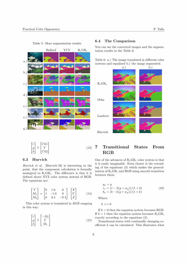
Table 5: More segmentation results..
Ballard YUV ReGBe
a.)
b.)
c.)
d.)
e.)
e.)
g.)
rgb
=̂
Ch1Y
Ch2
(13)
6.3 Hurvich
Hurvich et al. [Hurvich 56] is interesting in thepoint, that the component calculation is formallyanalogical to ReGBe. The difference is that it isdefined above XYZ color system instead of RGB.The equations are:
YM1
M2
=
0 1.0 01 −1.0 00 0.4 −0.4
.
XYZ
(14)
This color system is translated in RGB mappingin this way:
rgb
=̂
−M2
YM1
(15)
6.4 The Comparison
You can see the converted images and the segmen-tation results in the Table 6:
Table 6: a.) The image translated in different colorsystems and equalized b.) the image segmented.
a.) b.)
ReGBe
Otha
Lambert
Hurvich
7 Transitional States FromRGB
One of the advances of ReGBe color system is thatit is easily imaginable. Even clearer is the extend-ing of the equations (3) which makes the general-ization of ReGBe and RGB using smooth transitionbetween them:
gx = grx = (r − k(g + wg))/(1 + k)bx = (b− k(g + wg))/(1 + k)
(16)
Where:
k >= 0
If k = 0 then the equation system becomes RGB.If k = 1 then the equation system becomes ReGBe
exactly according to the equations (3).Transitional states with continually changing co-
efficient k can be calculated. This illustrates what
6
Practical Color Opponency P. Talla
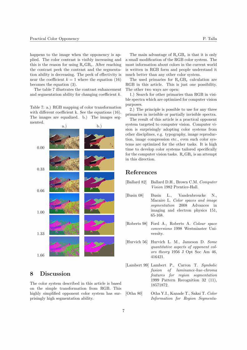
happens to the image when the opponency is ap-plied. The color contrast is visibly increasing andthis is the reason for using ReGBe. After reachingthe contrast peek the contrast and the segmenta-tion ability is decreasing. The peek of effectivity isnear the coefficient k = 1 where the equation (16)becomes the equation (3).
The table 7 illustrates the contrast enhancementand segmentation ability for changing coefficient k.
Table 7: a.) RGB mapping of color transformationwith different coefficient k. See the equations (16).The images are equalized. b.) The images seg-mented.
a.) b.)
0.00
0.33
0.66
1.00
1.33
1.66
8 Discussion
The color system described in this article is basedon the simple transformation from RGB. Thishighly simplified opponent color system has sur-prisingly high segmentation ability.
The main advantage of ReGBe is that it is onlya small modification of the RGB color system. Themost information about colors in the current worldis written in RGB form and people understand itmuch better than any other color system.
The used primaries for ReGBe calculation areRGB in this article. This is just one possibility.The other two ways are open:
1.) Search for other primaries than RGB in visi-ble spectra which are optimized for computer visionpurposes.
2.) The principle is possible to use for any threeprimaries in invisible or partially invisible spectra.
The result of this article is a practical opponentsystem targeted to computer vision. Computer vi-sion is surprisingly adopting color systems fromother disciplines, e.g. typography, image reproduc-tion, image compression etc., even such color sys-tems are optimized for the other tasks. It is hightime to develop color systems tailored specificallyfor the computer vision tasks. ReGBe is an attemptin this direction.
References
[Ballard 82] Ballard D.H., Brown C.M. ComputerVision 1982 Prentice-Hall.
[Busin 08] Busin L., Vandenbroucke N.,Macaire L. Color spaces and imagesegmentation 2008 Advances inimaging and electron physics 151,65-168.
[Roberts 98] Ford A., Roberts A. Colour spaceconversions 1998 Westminster Uni-versity.
[Hurvich 56] Hurvich L. M., Jameson D. Somequantitative aspects of opponent col-ors theory 1956 J Opt Soc Am 46,416421.
[Lambert 99] Lambert P., Carron T. Symbolicfusion of luminance-hue-chromafeatures for region segmentation1999 Pattern Recognition 32 (11),18571872.
[Otha 80] Otha Y.I., Kanade T., Sakai T. ColorInformation for Region Segmenta-
7

Practical Color Opponency P. Talla
tion 1980 Computer Graphics andImage Processing 13, 222-241.
8