a review of hydrogen/halogen flow cells - escholarship
TRANSCRIPT
A Review of Hydrogen/Halogen Flow Cells Kyu Taek Cho,[a] Michael C. Tucker,[b] and Adam Z. Weber*[b]
[a] Prof. K.T. Cho, Dept. of Mechanical Engineering Northern Illinois University Dekalb, IL 60115, USA
[b] Drs. A. Z Weber, M. C. Tucker Energy Conversion Group, Energy Technologies Area Lawrence Berkeley National Laboratory 1 Cyclotron Rd, MS70-108B, Berkeley, CA 94720 E-mail: [email protected]
Abstract
Flow batteries provide an energy-storage solution for various grid-related stability and service issues arising as renewable-energy-generation technologies are adopted. Among the most promising flow-battery systems are those using hydrogen/halogen redox couples, which promise the possibility to meet the DOE’s cost target, due to their fast and reversible kinetics and low materials cost. However, significant critical issues and barriers for their adoption remain. In this review of the halogen/hydrogen systems, the technical and performance issues, and research and development progress are reviewed. The information in this review can be used as a technical guide for research and development of related redox-flow-battery systems and other electrochemical technologies.
Contents
1. Introduction (Page #) 2. Historical overview
2.1. Hydrogen/chlorine system (Page #) 2.2. Hydrogen/bromine system (Page #)
3. Thermodynamic and transport properties of halogen chemicals
3.1. Equilibrium constant, enthalpy, entropy, and Gibbs free energy (Page #) 3.2. Equilibrium potential (Page #) 3.3. Solubility (Page #) 3.4. Vapor pressure (Page #) 3.5. Conductivity (Page #)
4. Electrodes 4.1. Halogen electrode
4.1.1. Kinetics and enhancement (Page #) 4.1.2. Effects of the tri-bromide complex (Page #)
4.2. Hydrogen electrode and anion adsorption (Page #) 5. Membrane
5.1 Transport properties of Nafion 5.1.1. Proton conductivity (Page #) 5.1.2. Electro-osmotic coefficient (Page #) 5.1.3. Permeability (crossover) (Page #) 5.1.4. Impact of equivalent weight and pretreatment 5.1.5. Effect of crossover on cell performance (Page #)
5.2. Other membrane types (Page #)
6. Flow field (Page #) 7. Durability of the H2/Br2 cell
7.1. Material compatibility (Page #) 7.2. Platinum dissolution and deactivation (Page #) 7.3. Long-term durability testing (Page #)
8. Summary and future outlook (Page #)
1. Introduction
Annual demand of electricity in North America is rapidly growing and is expected to increase between 15 to 50% above 2010 levels by 2050[1] and the conventional grid system needs to be modernized to accommodate this large demand. One promising method to do this is to use electrical-energy-storage (EES) devices combined with distributed generation to optimize the capability of the current grid system. Renewable resources, such as wind and solar energy, have been developed to supplement the fossil-fuel-based electricity demand. In particular, electricity generated from wind power is expected to reach 474 GW by 2020 and the United States has targeted 100 GW of solar power by 2020.[2] However, the intermittent generation of electricity from the renewable resources has restricted their active deployment. Therefore, EES is necessary to facilitate penetration of renewable resources, and it is estimated that the EES requirement in the US will be between 10 and 100 GW over the next 5 to 10 years, with an estimated market of $35 billion by 2020, and an EES DOE cost target of $100/kWh.[1, 3]
Various energy-storage systems have been developed, including thermal storage, supercapacitors, flywheels, pumped-hydro, and batteries. One of the most promising storage systems is the redox flow battery (RFB), which stores electrochemical energy in the form of oxidized and reduced electroactive chemical species present in flowing media, with excess media typically contained in external tanks. The redox flow cell sub-system produces or consumes power depending on the direction of the reversible electrochemical reaction, and is the subject of this review.[4] Such an architecture allows one to decouple energy and power, achieve high cycle life and deep charge/discharge operation owing to a lack of structural changes and stress buildup in the electrodes, have high inherent safety with nonreactive electrolytes and passive thermal management, and provide quick response. Therefore, the RFB is gaining intensive attention as one of the most promising and cost-effective EES systems for large EES needs from renewable resources. For example, recent techno-economic analyses demonstrate that hydrogen/halogen RFBs could be competitive with other technologies, especially at the 4 hour discharge time or so.[5] However, being an electrochemical technology, they can also provide benefits in other markets including frequency regulation as well as arbitrage and transmission and delivery deferrals.
RFBs can be classified based on the phases of the electroactive species:[6] fluid, solid, or hybrid. The fluid-phase RFB has reactants/products dissolved in liquid electrolytes or gases and chemical energy is stored in the liquid/gas phase. Typical systems include iron-chromium,[7] all-vanadium,[8]
[a] Prof. K. T. Cho Electrochemical and Thermal Energy Lab
Mechanical Engineering Northern Illinois University 1425 W Lincoln Hwy, Dekalb, IL 60115 (USA)
[b] Dr. M. Tucker, Dr. A. Z. Weber
Environmental Energy Technologies Division Lawrence Berkeley National Laboratory 1 Cyclotron Road, Berkeley, CA 94720 (USA)
E-mail: [email protected]
vanadium/ polyhalide,[9] vanadium/iron,[10] vanadium/cerium,[11] and vanadium/ manganese.[12] The solid-phase RFB has chemical energy stored in solid active materials on the electrode, and include soluble lead-acid,[13] zinc-nickel,[14] and zinc-manganese oxide.[15] The hybrid-type RFB has reactants/products in various phases (gas, liquid, and solid), examples include zinc-chlorine,[16] zinc-bromine,[17] zinc-cerium,[18] semi-solid Li-ion,[19] hydrogen-halogen,[5a, 5c, 20] and hydrogen-iron.[21] While many of these are promising as described in recent reviews,[2, 4b, 22] one of the most promising is the hydrogen/halogen system.
The hydrogen/halogen system is getting attention due to its fast, reversible kinetics that lead to excellent performance and low-cost reactant materials.
Prof. K. T. Cho received his Ph.D. from Pennsylvania State University, 2010 under the guidance of Prof. M. Mench after 10 years work at Hyundai Motor Company, S. Korea as a senior researcher to develop fuel cell vehicle systems. After post-doctoral research at the Lawrence Berkeley National Lab, he accepted a position as Assistant Professor at the Northern Illinois University in 2014. His research interests include advanced electrochemical energy systems such as flow batteries, fuel cells, and batteries and advanced thermal energy system utilizing nanofluids.
Dr. M.C. Tucker received his B.Sc. from Brown University in 1997, and his Ph.D. from University of California, Berkeley with Profs. J. Reimer and E. Cairns in 2001. His postdoctoral research was in the lab of Prof. J. Thomas (Uppsala University, Sweden). He is now Research Scientist at Lawrence Berkeley National Laboratory, Energy Conversion Group. His research interests focus on electrochemical device development, including flow batteries, solid oxide fuel cells, and PEM fuel cells. Dr. A. Z. Weber received his B.Sc and M.Sc. degrees from Tufts University in 1999, and his Ph.D. from University of California, Berkeley in 2004 under the gudiance of J. Newman. He then moved to Lawrence Berkeley National Laboratory where he is now a staff scientist and leader of the Energy Conversion Group. His interestes and research focus on electrochemical technologies including flow batteries, fuel cells, and solar-fuel generators. He received a Presidential Early Career Award for Scientists and Engineers (PECASE) in 2012 and the Charles W. Tobias Young Investigaotr Award fo the Electrochemical Society in 2014.
Figure 1 Schematic of hydrogen-bromine RFB[20b].Discharge processes are indicated with solid lines; dashed lines indicate the reverse (charge) reactions. Note that hydrogen exits the (-) electrode during the typical use case of above-stoichiometric flow rates.
Figure 1 shows a schematic of a hydrogen-halogen RFB. H2
gas is supplied to the negative-electrode (-) side, while X2, typically dissolved in an aqueous solution of HX, is provided to the positive-electrode (+) side. During discharge operation, H2 is oxidized (typically at a precious-metal electrocatalyst), and halogen is simultaneously reduced to halogen anion (typically at
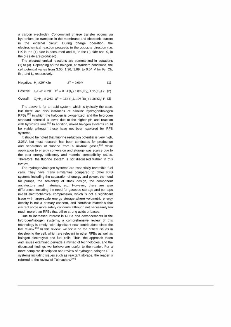
a carbon electrode). Concomitant charge transfer occurs via hydronium-ion transport in the membrane and electronic current in the external circuit. During charge operation, the electrochemical reaction proceeds in the opposite direction (i.e. HX in the (+) side is consumed and H2 in the (-) side and X2 in the (+) side are produced).
The electrochemical reactions are summarized in equations (1) to (3). Depending on the halogen, at standard conditions, the cell potential varies from 3.05, 1.36, 1.09, to 0.54 V for F2, Cl2, Br2, and I2, respectively. Negative: H2⇄2H++2e- 𝐸0 = 0.00 𝑉 (1)
Positive: X2+2e- ⇄ 2X- 𝐸0 = 0.54 (I2), 1.09 (Br2), 1.36(Cl2) 𝑉 (2)
Overall: X2+H2 ⇄ 2HX 𝐸0 = 0.54 (I2), 1.09 (Br2), 1.36(Cl2) 𝑉 (3)
The above is for an acid system, which is typically the case, but there are also instances of alkaline hydrogen/halogen RFBs,[23] in which the halogen is oxygenized, and the hydrogen standard potential is lower due to the higher pH and reaction with hydroxide ions.[24] In addition, mixed halogen systems could be viable although these have not been explored for RFB systems.
It should be noted that fluorine reduction potential is very high, 3.05V, but most research has been conducted for production and separation of fluorine from a mixture gases,[25] while application to energy conversion and storage was scarce due to the poor energy efficiency and material compatibility issues. Therefore, the fluorine system is not discussed further in this review.
The hydrogen/halogen systems are essentially reversible fuel cells. They have many similarities compared to other RFB systems including the separation of energy and power, the need for pumps, the scalability of stack design, the component architecture and materials, etc. However, there are also differences including the need for gaseous storage and perhaps in-cell electrochemical compression, which is not a significant issue with large-scale energy storage where volumetric energy density is not a primary concern, and corrosive materials that warrant some more safety concerns although not necessarily too much more than RFBs that utilize strong acids or bases.
Due to increased interest in RFBs and advancements in the hydrogen/halogen systems, a comprehensive review of this technology is timely, with significant new contributions since the last review.[26] In this review, we focus on the critical issues in developing the cell, which are relevant to other RFBs as well as halogen electrolysis and fuel cells. Thus, the approach taken and issues examined pervade a myriad of technologies, and the discussed findings we believe are useful to the reader. For a more complete description and review of hydrogen-halogen RFB systems including issues such as reactant storage, the reader is referred to the review of Tolmachev.[26a]
2. Historical overview
In this section, the research and development of hydrogen-halogen RFBs is historically overviewed, with a structure to guide the reader based on major research findings from various groups, and not purely chronologically in order. This section focuses on major technical progress of hydrogen/chlorine and hydrogen/bromine systems published in the open domain. The hydrogen/iodine and hydrogen/fluorine systems are not addressed in this section due to lack of reported research for their use in RFB EES, probably due to the low theoretical voltage for iodine, and materials compatibility issues for fluorine.[26] This is reinforced by the study of Balko[27] who investigated the efficiency and heat-rejection characteristics of various hydrogen/halogen systems by computer simulation. It was found that the H2/Cl2 and H2/Br2 systems are comparable with respect to efficiency, heat rejection and fuel mass, but the H2/I2 system is markedly less efficient. However, it should be noted that the hydrogen/iodine system could have applications for thermal or solar regenerated cells.[26a]
Advantages of the H2/Br2 system for energy storage were highlighted, such as the existence of bromine in the liquid state at ambient pressure and temperature which simplifies fuel storage, and the lower reversible potential of bromine (compared to chlorine) which reduces inefficiency associated with oxygen evolution, a competetive side reaction at higher voltage on charge.[28] Below, we examine the two main hydrogen/halogen systems in terms of their historical research findings and groups producing the work.
2.1. Hydrogen/chlorine system
Early study of hydrogen/chlorine cell was conducted by Yoshizawa et al. They reported a new electrochemical system, replacing the conventional combustion method, to produce hydrogen chloride efficiently with the additional benefit of recovering electrical energy.[29]
Hydrogen/chlorine cell research was actively conducted by Brookhaven National Laboratory and General Electric Company.[30] Gileadi et al. proposed the electrolysis of HCl and storage of hydrogen and chlorine as a promising ESS for electric utilities.[30a] With detailed economic evaluation, they decided the HCl system was advantageous over the hydrogen/air system and comparable in cost to gas turbines, with the possible benefit of hydrogen production. Srinivasan and coworkers studied the cell behavior both experimentally and theoretically.[30b-d] They explored different operating parameters, electrode materials, and flow-field designs in order to optimize cell performance. Significant findings include the need to operate at increased pressures to increase Cl2 solubility, and the need for forced convection via flow-through instead of flow-by positive electrodes. These key parameters greatly reduced the kinetic resistances, resulting in linear polarization behavior.
In addition to the above studies, Maricle et al.[31] at United Technology Corporation invented regenerative fuel cells based on hydrogen and chlorine in aqueous and anhydrous conditions as the reactive species. Also, Anderson[32] at PSI Technology
conducted a feasibility study of the H2/Cl2 cell for space-power applications for NASA due to the benefit of the high power density of the system. They identified the need to develop high performance, long-lived chlorine gas-diffusion electrodes and chloride-tolerant hydrogen negative electrodes.
Research to enhance performance and durability by using new materials and elucidate transport properties was conducted. Shibli et al.[33] explored new materials for chlorine and hydrogen electrodes, an found an electrode containing 2.5 wt.-% Pt and 5 wt.-% Ir to be highly effective for both hydrogen oxidation and chlorine reduction. The resultant H2/Cl2 fuel cell produced a voltage of 1.0 V at a current density of 100 mA/cm2, and was operated for 300 hrs without degradation.
Motupally et al.[34] analyzed membrane transport properties to characterize the diffusion and the electro-osmotic flux in the presence of HCl.
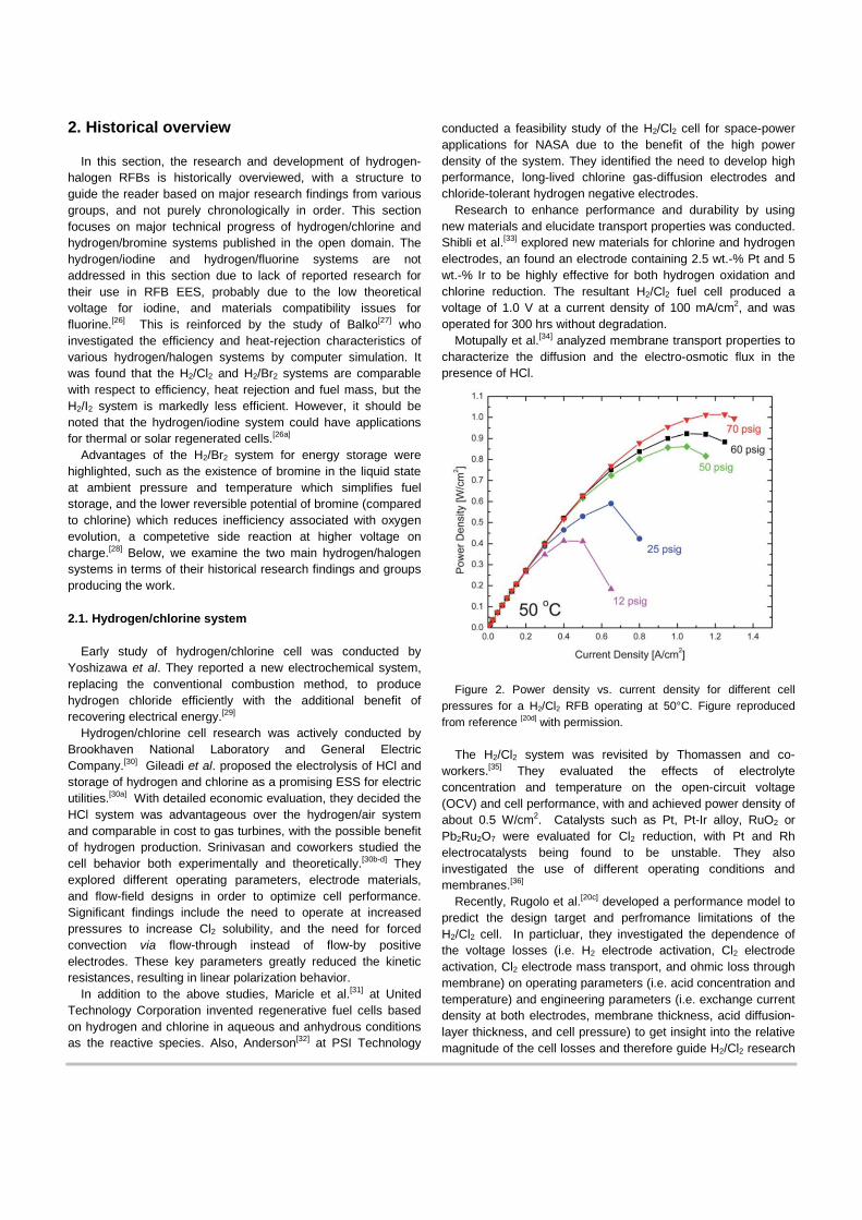
Figure 2. Power density vs. current density for different cell
pressures for a H2/Cl2 RFB operating at 50°C. Figure reproduced from reference [20d] with permission.
The H2/Cl2 system was revisited by Thomassen and co-
workers.[35] They evaluated the effects of electrolyte concentration and temperature on the open-circuit voltage (OCV) and cell performance, with and achieved power density of about 0.5 W/cm2. Catalysts such as Pt, Pt-Ir alloy, RuO2 or Pb2Ru2O7 were evaluated for Cl2 reduction, with Pt and Rh electrocatalysts being found to be unstable. They also investigated the use of different operating conditions and membranes.[36]
Recently, Rugolo et al.[20c] developed a performance model to predict the design target and perfromance limitations of the H2/Cl2 cell. In particluar, they investigated the dependence of the voltage losses (i.e. H2 electrode activation, Cl2 electrode activation, Cl2 electrode mass transport, and ohmic loss through membrane) on operating parameters (i.e. acid concentration and temperature) and engineering parameters (i.e. exchange current density at both electrodes, membrane thickness, acid diffusion-layer thickness, and cell pressure) to get insight into the relative magnitude of the cell losses and therefore guide H2/Cl2 research
and development. Based on the modeling results, Huskinson et al.[20d] achieved 1 W/cm2 as a peak power density with a low precious-metal content alloy oxide, (Ru0.09Co0.91)3O4, for the chlorine electrode. Virtually no activation losses were observed as shown in Figure 2, suggesting this system is promising for grid-scale EES device.
2.2. Hydrogen/bromine system
The first studies of the H2/Br2 cell were conducted in the 1960s by Glass and Boyle[37] and Juda et al.[38] They concluded the H2/Br2 system to be advantageous over the H2/O2 system due to the more facile reaction of Br2 vs. O2, despite issues including higher corrosivity, higher cell ohmic resistance, and an open-circuit voltage that is more dependent on state of charge. They conducted extensive studies on the the H2/Br2 system including cell construction, electrode, electrolyte, and membrane related issues. Crossover of bromine-containing species through the membrane was identified as a key issue causing reduced overall cell efficiency.
Yeo and McBreen[39] determined in-membrane permeation rates and diffusivities in various HCl and HBr environments over a range of temperatures for H2, Cl2, and Br2. It was found that the transport properties of these species in the ion-exchange membrane (NafionTM) 1 are largely determined by its water content. Feasibility of the H2/Br2 cell for EES applications was investigated by Yeon and Chin.[40] They concluded that improvement in membrane conductivity is vital in the design of efficient cells because the voltaic efficiency is dominated by membrane conductivity and associated ohmic losses. They also reported membrane-property hysteresis due to interaction between the membrane and external electrolyte solution, the proton concetration of which changes during charge and discharge cycling. It was suggested that the cell should be filled with water or dilute HBr acid to minimize dehydration of membrane, especially when the cell is idle for a long period of time.
Bromine crossover was further explored by Will [41] at GE. In particular, the diffusion coefficient and flux of bromine through Nafion membrane were established as a function of the membrane equivalent weight and its pretreatment and electrolyte concentration, and it was found that the diffusion coefficient increases significantly with decreasing membrane equivalent weight.
Kosek and Laconti[42] developed a bromine storage system based on the formation of a complex between polyethylene glycol (PEG) and bromine, to reduce the halogen vapor pressure and therefore mitigate materials corrosion issues. Physical and chemical properties of the PEG-Br2 complex were evaluated, including rate constants for dissociation of the complex. It was also determined that Ru-Ir positive-electrode catalyst is stable in HBr-PEG-Br2 environment and Pt-black catalyst for the negative side should be maintained at the hydrogen potential to prevent it from being dissolved or poisoned by crossover HBr/Br.
1 Nafion is a registered trademark of DuPont.
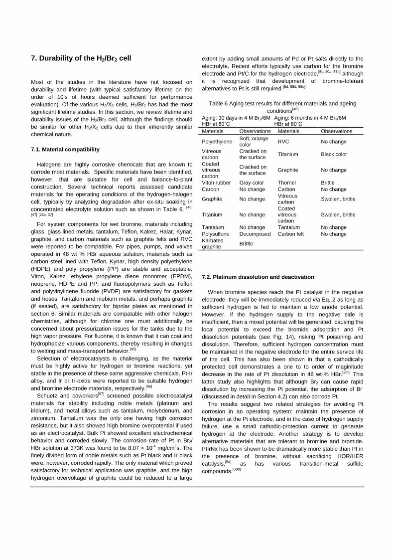
Barna et al.[43] conducted life-time testing of H2/Br2 fuel cells. After having completed 235,896 h of cumulative testing, with individual tests exceeding 10,000 h, the main parameters determining the lifetime were found to be the nature of the negative electrode and the properties of the membrane. In particular, Pt catalyst activity decayed, and Pt deactivation (i.e. Pt loss) was caused due to inadvertent brief pulsing of the negative electrode potential to high positive values at which Br2 is generated within the electrode. However, in the normal operating mode, any Br2 diffusing to the negative side will be immediately reduced since the negative electrode is at the reversible hydrogen potential, and therefore there should be no loss of Pt as long as the H2 supply is maintained. A trade-off was found in designing the negative electrode; if it is made to be more hydrophobic, it will enhance operating endurance but reduce performance.
Hohne and Starbeck[44] at Siemens disclosed a cell structure for the hydrogen-bromine system, with a cell frame covered with thin pyrographite layer for light weight and high corrosion-resistance.
Baldwin[45] investigated the electrochemical performance and transport properties of a Nafion membrane in the H2/Br2 cell. Membrane conductivity was measured as a function of HBr concentration and temperature to determine the ohmic voltage loss across the membrane in an operating cell, and bromine permeation rate (i.e. permeability) was reported with respect to solution composition and temperature. Relationships between the degree of membrane hydration and membrane transport characteristics were discussed. Charleston and Reed[46] conducted accelerated aging tests of various materials in the acidic cell environment to identify compatible and durable materials for use in the H2/Br2 flow cell.
Kosek and Laconti [47] developed binary platinum alloys as hydrogen electrocatalysts for use in the H2/Br2 RFB. The elemental ratio and heat treatment temperature of the alloys was varied. Platinum-rich alloy was found to have the best tolerance to bromide-ion poisoning.
Savinell and Fritts [48] used theoretical and experimental studies of a H2/Br2 fuel cell to estimate the open circuit potential (OCV) for various SOCs. They also formulated a mathematical model to describe cell performance and conducted a parametric study into the effects of kinetics, mass transfer, and design parameters on cell performance.[49] The local current density distribution in the porous bromine electrode was examined, and the electrochemical reaction was found to take place predominately in regions near the membrane. The effect of electrode thickness on cell performance was determined at constant electrolyte velocity, and electrode thickness greater than 1.8 mm provided only marginal improvement in cell performance. They also conducted simulation studies on the performance of the hydrogen electrode bonded to the membrane to understand the transport of protons and dissolved hydrogen in the reaction zone.[50]
Fundamental aspects of bromide adsorption on Pt were investigated by Marković et. al using rotating ring disk electrode and surface X-ray scattering measurements. In particular, the saturation coverage of hydrogen adsorption in the presence of Br- is about the same as in a Br- free-solution (~210 µC cm-2), but the potential region for the onset of hydrogen adsorption is shifted negatively by 0.35V due to the competition with Br- adsorption.[51]
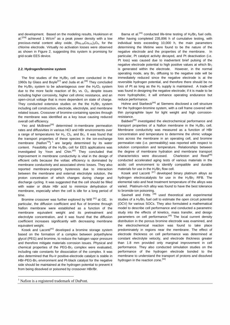
More recently, extensive development of the H2/Br2 system was conducted by Peled’s group at Tel-Aviv University. Livshits et al[52] reported the properties and performance of the H2/Br2 flow cell based on a nanoporous conducting membrane (NP-PCM) as shown in Fig. 3. A maximum power density above 1.5 W/cm2 was achieved in a 5 cm2 cell with Pt-loaded catalyst for both cathode and anode (i.e. 1.5 mg/cm2 for cathode and 1 mg/cm2 for anode) and 100 µm thick NP-PCM, and this remains the highest reported power density for this system. Their company, EnStorage,[53] successfully demonstrated a 150 kW (900 kWh) flow battery for grid-scale EES.[54] Goor-Dar et al.[55] studied the adsorption of bromide ions and the hydrogen redox reactions on XC 72-supported Pt nanoparticles in concentrated HBr solution using rotating disk electrode and cyclic voltammetry.
Figure 3 Effect of temperature and bromine concentration on performance of a H2/Br2 cell with a NP-PCM membrane. Figure reproduced from reference [52] with permission.
The gas-phase Br2/H2 flow cell was studied by Zhang and Weidner[56], and their analysis revealed that gas-phase Br2/HBr reactants significantly enhanced mass transfer, which enables higher current densities to be achieved, compared to a liquid-fed system, although the charge reactions are much less facile.
The H2/Br2 system was revisited by Lawrence Berkeley National Laboratory and partners to develop it as a grid-scale EES.[5c, 5d, 20a, 20b, 57] They conducted extensive research including: fundamental kinetic studies to find low-cost, stable electrode materials; elucidation of the mechanism of proton transport in the membrane and interrelation with ions in the electrolyte; cell optimization to determine critical design factors; long-term cell tests to explore durability concerns; and, cost modeling to determine the main drivers for system cost
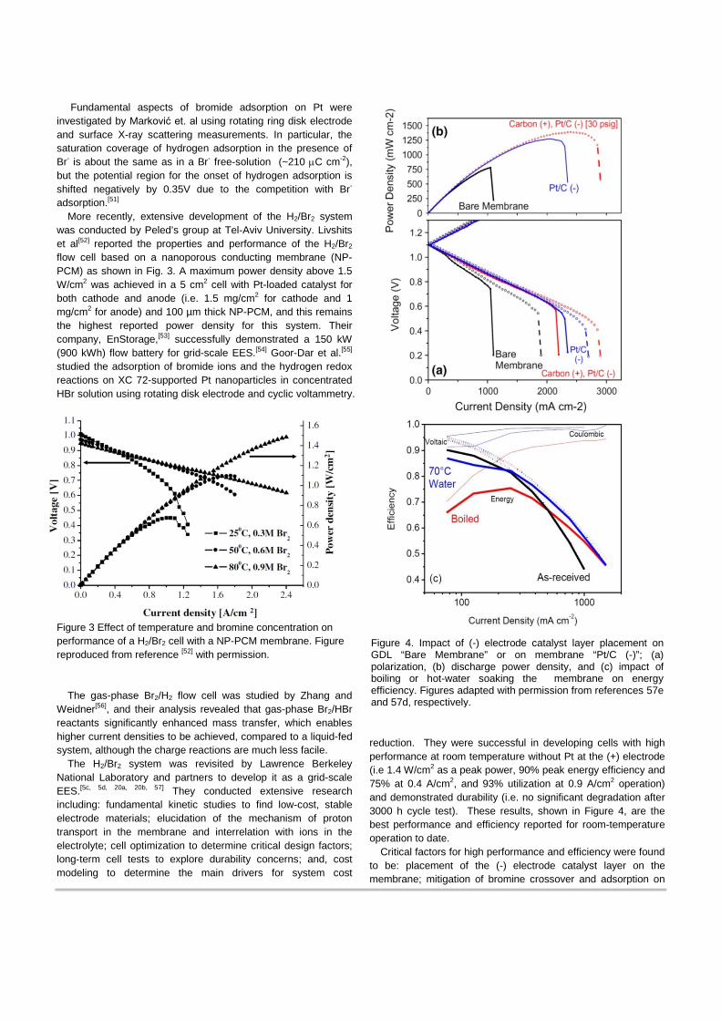
reduction. They were successful in developing cells with high performance at room temperature without Pt at the (+) electrode (i.e 1.4 W/cm2 as a peak power, 90% peak energy efficiency and 75% at 0.4 A/cm2, and 93% utilization at 0.9 A/cm2 operation) and demonstrated durability (i.e. no significant degradation after 3000 h cycle test). These results, shown in Figure 4, are the best performance and efficiency reported for room-temperature operation to date.
Critical factors for high performance and efficiency were found to be: placement of the (-) electrode catalyst layer on the membrane; mitigation of bromine crossover and adsorption on
Figure 4. Impact of (-) electrode catalyst layer placement on GDL “Bare Membrane” or on membrane “Pt/C (-)”; (a) polarization, (b) discharge power density, and (c) impact of boiling or hot-water soaking the membrane on energy efficiency. Figures adapted with permission from references 57e and 57d, respectively.
Pt; membrane and (+) electrode thickness; appropriate pre-treatment of the membrane; and, swelling (hydration) state of the membrane during cell assembly, some of which are illustrated in Fig. 4.
A consortium of researchers developed new materials to further address cell performance and system cost under the US ARPA-E GRIDS program.[5d] The impact of membrane conductivity was found to be significant in optimizing the cell performance and thus lowering the system cost. Cost-modeling demonstrated that higher concentration of RFB reactants do not necessarily result in lower capital cost, as there is a trade-off between cell performance and storage requirements as shown in Fig. 5.[5c]
Figure 5. H2/Br2 RFB system capital cost as a function of HBr concentration for two discharge times. Figure reproduced from reference [5c] with permission.
Nguyen and coworkers[5d, 58] conducted performance
evaluation and modeling of the H2/Br2 RFB and compared the performance of H2/O2 and H2/Br2 systems. They found that the performance of H2/Br2 is determined mainly by the ohmic and mass-transfer resistance, leading to increased performance as flow-through designs were adopted. They also explored alternative materials for the negative and positive electrodes, and membrane.
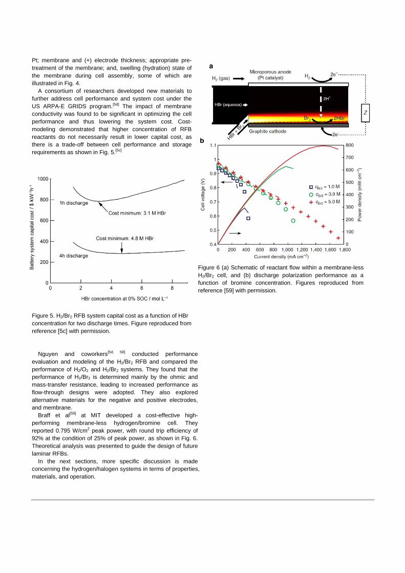
Braff et al[59] at MIT developed a cost-effective high-performing membrane-less hydrogen/bromine cell. They reported 0.795 W/cm2 peak power, with round trip efficiency of 92% at the condition of 25% of peak power, as shown in Fig. 6. Theoretical analysis was presented to guide the design of future laminar RFBs.
In the next sections, more specific discussion is made concerning the hydrogen/halogen systems in terms of properties, materials, and operation.
Figure 6 (a) Schematic of reactant flow within a membrane-less H2/Br2 cell, and (b) discharge polarization performance as a function of bromine concentration. Figures reproduced from reference [59] with permission.
3. Thermodynamic and transport properties of halogen chemicals
In this section, thermodynamic and transport properties of halogen chemicals will be briefly summarized, and the efficiency of the hydrogen/halogen systems will be addressed. The desire for high energy-storage capacity motivates the use of the highest reactant concentration possible. The thermodynamic properties, however, constrain the useful concentration range for a system optimized for efficiency, power, and cost. For detailed information of thermodynamic properties, the readers are referred to the literature.[60]
3.1. Equilibrium constant, enthalpy, entropy, and Gibbs free energy
The hydrogen/halogen reaction takes place spontaneously to produce hydrogen halide (i.e. discharge in Fig. 1) due to the inherent electrochemical-potential differences between hydrogen and halogen. For charge, assuming a reversible system, the equivalent amount of electrical energy needs to be applied to the cell (equation 3). This quantity is related to the Gibbs free energy of the reactions, where at standard conditions including unit acivity (1 M or 1 bar for aqueous or gas species, respectively), one can equate them as
𝐸𝑐𝑐𝑐𝑐0 = ∆𝐺2𝐹
(4)
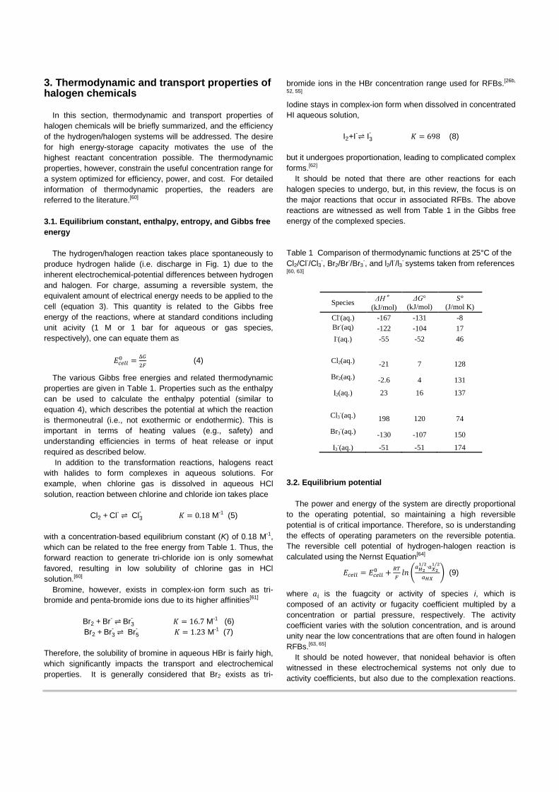
The various Gibbs free energies and related thermodynamic properties are given in Table 1. Properties such as the enthalpy can be used to calculate the enthalpy potential (similar to equation 4), which describes the potential at which the reaction is thermoneutral (i.e., not exothermic or endothermic). This is important in terms of heating values (e.g., safety) and understanding efficiencies in terms of heat release or input required as described below.
In addition to the transformation reactions, halogens react with halides to form complexes in aqueous solutions. For example, when chlorine gas is dissolved in aqueous HCl solution, reaction between chlorine and chloride ion takes place
Cl2 + Cl- ⇌ Cl3
- 𝐾 = 0.18 M-1 (5)
with a concentration-based equilibrium constant (K) of 0.18 M-1, which can be related to the free energy from Table 1. Thus, the forward reaction to generate tri-chloride ion is only somewhat favored, resulting in low solubility of chlorine gas in HCl solution.[60]
Bromine, however, exists in complex-ion form such as tri-bromide and penta-bromide ions due to its higher affinities[61]
Br2 + Br- ⇌ Br3- 𝐾 = 16.7 M-1 (6)
Br2 + Br3- ⇌ Br5
- 𝐾 = 1.23 M-1 (7) Therefore, the solubility of bromine in aqueous HBr is fairly high, which significantly impacts the transport and electrochemical properties. It is generally considered that Br2 exists as tri-
bromide ions in the HBr concentration range used for RFBs.[26b,
52, 55] Iodine stays in complex-ion form when dissolved in concentrated HI aqueous solution,
I2+I-⇌ I3
- 𝐾 = 698 (8) but it undergoes proportionation, leading to complicated complex forms.[62]
It should be noted that there are other reactions for each halogen species to undergo, but, in this review, the focus is on the major reactions that occur in associated RFBs. The above reactions are witnessed as well from Table 1 in the Gibbs free energy of the complexed species.
Table 1 Comparison of thermodynamic functions at 25°C of the Cl2/Cl-/Cl3-, Br2/Br-/Br3
-, and l2/l-/l3- systems taken from references [60, 63]
Species ΔH°
(kJ/mol) ΔG°
(kJ/mol) S°
(J/mol K) Cl-(aq.) -167 -131 -8 Br-(aq) -122 -104 17 I-(aq.) -55 -52 46
Cl2(aq.) -21 7 128
Br2(aq.) -2.6 4 131
I2(aq.) 23 16 137
Cl3-(aq.) 198 120 74
Br3-(aq.) -130 -107 150
I3-(aq.) -51 -51 174
3.2. Equilibrium potential
The power and energy of the system are directly proportional to the operating potential, so maintaining a high reversible potential is of critical importance. Therefore, so is understanding the effects of operating parameters on the reversible potentia. The reversible cell potential of hydrogen-halogen reaction is calculated using the Nernst Equation[64]
𝐸𝑐𝑐𝑐𝑐 = 𝐸𝑐𝑐𝑐𝑐0 + 𝑅𝑅𝐹𝑙𝑙 �
𝑎𝐻21/2∙𝑎𝑋2
1/2
𝑎𝐻𝑋� (9)
where 𝑎𝑖 is the fuagcity or activity of species i, which is composed of an activity or fugacity coefficient multipled by a concentration or partial pressure, respectively. The activity coefficient varies with the solution concentration, and is around unity near the low concentrations that are often found in halogen RFBs.[63, 65]
It should be noted however, that nonideal behavior is often witnessed in these electrochemical systems not only due to activity coefficients, but also due to the complexation reactions.
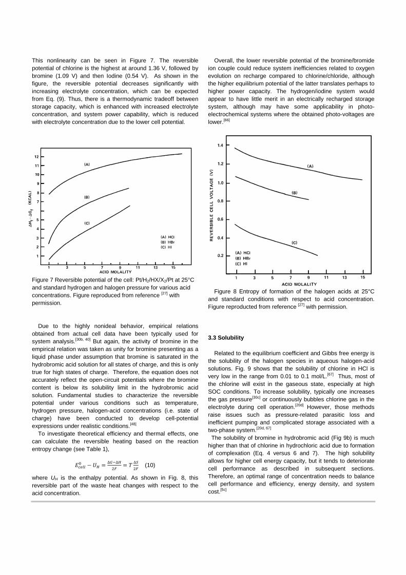
This nonlinearity can be seen in Figure 7. The reversible potential of chlorine is the highest at around 1.36 V, followed by bromine (1.09 V) and then Iodine (0.54 V). As shown in the figure, the reversible potential decreases significantly with increasing electrolyte concentration, which can be expected from Eq. (9). Thus, there is a thermodynamic tradeoff between storage capacity, which is enhanced with increased electrolyte concentration, and system power capability, which is reduced with electrolyte concentration due to the lower cell potential.
Figure 7 Reversible potential of the cell: Pt/H2/HX/X2/Pt at 25°C and standard hydrogen and halogen pressure for various acid concentrations. Figure reproduced from reference [27] with permission.
Due to the highly nonideal behavior, empirical relations obtained from actual cell data have been typically used for system analysis.[30b, 40] But again, the activity of bromine in the empirical relation was taken as unity for bromine presenting as a liquid phase under assumption that bromine is saturated in the hydrobromic acid solution for all states of charge, and this is only true for high states of charge. Therefore, the equation does not accurately reflect the open-circuit potentials where the bromine content is below its solubility limit in the hydrobromic acid solution. Fundamental studies to characterize the reversible potential under various conditions such as temperature, hydrogen pressure, halogen-acid concentrations (i.e. state of charge) have been conducted to develop cell-potential expressions under realistic conditions.[48]
To investigate theoretical efficiency and thermal effects, one can calculate the reversible heating based on the reaction entropy change (see Table 1),
𝐸𝑐𝑐𝑐𝑐0 − 𝑈𝐻 = ∆𝐺−∆𝐻
2𝐹= 𝑇 ∆𝑆
2𝐹 (10)
where UH is the enthalpy potential. As shown in Fig. 8, this reversible part of the waste heat changes with respect to the acid concentration.
Overall, the lower reversible potential of the bromine/bromide ion couple could reduce system inefficiencies related to oxygen evolution on recharge compared to chlorine/chloride, although the higher equilibrium potential of the latter translates perhaps to higher power capacity. The hydrogen/iodine system would appear to have little merit in an electrically recharged storage system, although may have some applicability in photo-electrochemical systems where the obtained photo-voltages are lower.[66]
Figure 8 Entropy of formation of the halogen acids at 25°C and standard conditions with respect to acid concentration. Figure reproducted from reference [27] with permission.
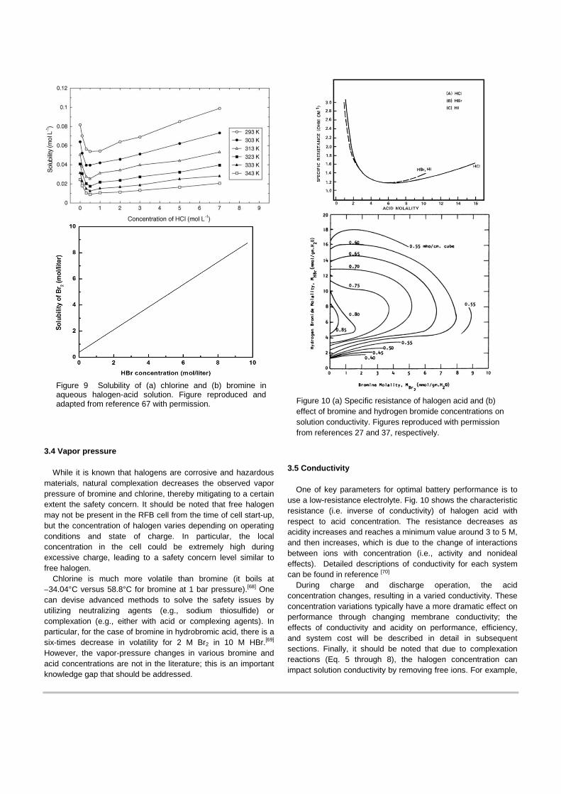
3.3 Solubility
Related to the equilibrium coefficient and Gibbs free energy is the solubility of the halogen species in aqueous halogen-acid solutions. Fig. 9 shows that the solubility of chlorine in HCl is very low in the range from 0.01 to 0.1 mol/L.[67] Thus, most of the chlorine will exist in the gaseous state, especially at high SOC conditions. To increase solubility, typically one increases the gas pressure[30c] or continuously bubbles chlorine gas in the electrolyte during cell operation.[20d] However, those methods raise issues such as pressure-related parasitic loss and inefficient pumping and complicated storage associated with a two-phase system.[20d, 67] The solubility of bromine in hydrobromic acid (Fig 9b) is much higher than that of chlorine in hydrochloric acid due to formation of complexation (Eq. 4 versus 6 and 7). The high solubility allows for higher cell energy capacity, but it tends to deteriorate cell performance as described in subsequent sections. Therefore, an optimal range of concentration needs to balance cell performance and efficiency, energy density, and system cost.[5c]
3.4 Vapor pressure
While it is known that halogens are corrosive and hazardous materials, natural complexation decreases the observed vapor pressure of bromine and chlorine, thereby mitigating to a certain extent the safety concern. It should be noted that free halogen may not be present in the RFB cell from the time of cell start-up, but the concentration of halogen varies depending on operating conditions and state of charge. In particular, the local concentration in the cell could be extremely high during excessive charge, leading to a safety concern level similar to free halogen.
Chlorine is much more volatile than bromine (it boils at −34.04°C versus 58.8°C for bromine at 1 bar pressure).[68] One can devise advanced methods to solve the safety issues by utilizing neutralizing agents (e.g., sodium thiosulfide) or complexation (e.g., either with acid or complexing agents). In particular, for the case of bromine in hydrobromic acid, there is a six-times decrease in volatility for 2 M Br2 in 10 M HBr.[69] However, the vapor-pressure changes in various bromine and acid concentrations are not in the literature; this is an important knowledge gap that should be addressed.
3.5 Conductivity
One of key parameters for optimal battery performance is to use a low-resistance electrolyte. Fig. 10 shows the characteristic resistance (i.e. inverse of conductivity) of halogen acid with respect to acid concentration. The resistance decreases as acidity increases and reaches a minimum value around 3 to 5 M, and then increases, which is due to the change of interactions between ions with concentration (i.e., activity and nonideal effects). Detailed descriptions of conductivity for each system can be found in reference [70]
During charge and discharge operation, the acid concentration changes, resulting in a varied conductivity. These concentration variations typically have a more dramatic effect on performance through changing membrane conductivity; the effects of conductivity and acidity on performance, efficiency, and system cost will be described in detail in subsequent sections. Finally, it should be noted that due to complexation reactions (Eq. 5 through 8), the halogen concentration can impact solution conductivity by removing free ions. For example,
Figure 9 Solubility of (a) chlorine and (b) bromine in aqueous halogen-acid solution. Figure reproduced and adapted from reference 67 with permission. Figure 10 (a) Specific resistance of halogen acid and (b)
effect of bromine and hydrogen bromide concentrations on solution conductivity. Figures reproduced with permission from references 27 and 37, respectively.

Fig. 10b shows a conductivity map with respect to bromide and bromine concentration, where there are distinct maxima.[37]
4. Electrodes
Electrode materials for the halogen reaction have been selected on the basis of cost, stability, and compatibility in the corrosive working environment. Typically, carbon is utilized as the electrode material, even though the halogen reaction rate on carbon is lower than on noble materials such as Pt and Pd, and increasing the rate on carbon is an active area of research.
For the hydrogen electrode, the dominant catalyst choice is Pt due to its uniquely high kinetics in acid, even though there is risk of Pt deactivation arising from bromide migration through the membrane and subsequent adsorption to the Pt. Substantial research has focused on understanding the mechanism of poisoning and developing mitigation strategies. In this section, major contributions on carbon and Pt electrocatalysts are summarized.
4.1. Halogen electrode
4.1.1. Kinetics and enhancement
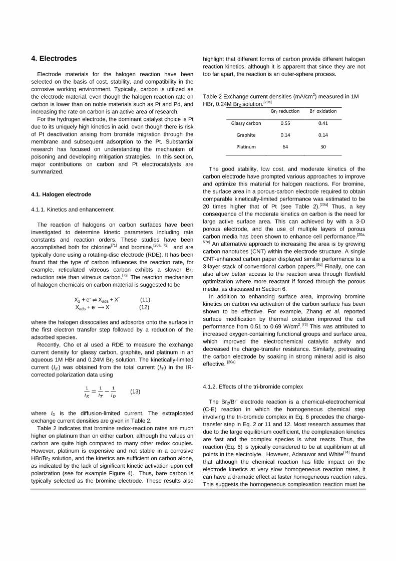
The reaction of halogens on carbon surfaces have been investigated to determine kinetic parameters including rate constants and reaction orders. These studies have been accomplished both for chlorine[71] and bromine,[20a, 72] and are typically done using a rotating-disc electrode (RDE). It has been found that the type of carbon influences the reaction rate, for example, reticulated vitreous carbon exhibts a slower Br2 reduction rate than vitreous carbon.[72] The reaction mechanism of halogen chemicals on carbon material is suggested to be
X2 + e- ⇌ Xads + X- (11) Xads + e- ⟶ X- (12)
where the halogen dissocaites and adbsorbs onto the surface in the first electron transfer step followed by a reduction of the adsorbed species.
Recently, Cho et al used a RDE to measure the exchange current density for glassy carbon, graphite, and platinum in an aqueous 1M HBr and 0.24M Br2 solution. The kinetically-limited current (𝐼𝐾) was obtained from the total current (𝐼𝑅) in the IR-corrected polarization data using
1𝐼𝐾
= 1𝐼𝑇− 1
𝐼𝐷 (13)
where ID is the diffusion-limited current. The extraploated exchange current densities are given in Table 2.
Table 2 indicates that bromine redox-reaction rates are much higher on platinum than on either carbon, although the values on carbon are quite high compared to many other redox couples. However, platinum is expensive and not stable in a corrosive HBr/Br2 solution, and the kinetics are sufficient on carbon alone, as indicated by the lack of significant kinetic activation upon cell polarization (see for example Figure 4). Thus, bare carbon is typically selected as the bromine electrode. These results also
highlight that different forms of carbon provide different halogen reaction kinetics, although it is apparent that since they are not too far apart, the reaction is an outer-sphere process. Table 2 Exchange current densities (mA/cm2) measured in 1M HBr, 0.24M Br2 solution.[20a]
Br2 reduction Br- oxidation
Glassy carbon 0.55 0.41
Graphite 0.14 0.14
Platinum 64 30
The good stability, low cost, and moderate kinetics of the
carbon electrode have prompted various approaches to improve and optimize this material for halogen reactions. For bromine, the surface area in a porous-carbon electrode required to obtain comparable kinetically-limited performance was estimated to be 20 times higher that of Pt (see Table 2).[20a] Thus, a key consequence of the moderate kinetics on carbon is the need for large active surface area. This can achieved by with a 3-D porous electrode, and the use of multiple layers of porous carbon media has been shown to enhance cell performance.[20a,
57e] An alternative approach to increasing the area is by growing carbon nanotubes (CNT) within the electrode structure. A single CNT-enhanced carbon paper displayed similar performance to a 3-layer stack of conventional carbon papers.[5d] Finally, one can also allow better access to the reaction area through flowfield optimization where more reactant if forced through the porous media, as discussed in Section 6.
In addition to enhancing surface area, improving bromine kinetics on carbon via activation of the carbon surface has been shown to be effective. For example, Zhang et al. reported surface modification by thermal oxidation improved the cell performance from 0.51 to 0.69 W/cm2.[73] This was attributed to increased oxygen-containing functional groups and surface area, which improved the electrochemical catalytic activity and decreased the charge-transfer resistance. Similarly, pretreating the carbon electrode by soaking in strong mineral acid is also effective. [20a]
4.1.2. Effects of the tri-bromide complex
The Br2/Br- electrode reaction is a chemical-electrochemical (C-E) reaction in which the homogeneous chemical step involving the tri-bromide complex in Eq. 6 precedes the charge-transfer step in Eq. 2 or 11 and 12. Most research assumes that due to the large equilibrium coefficient, the complexation kinetics are fast and the complex species is what reacts. Thus, the reaction (Eq. 6) is typically considered to be at equilibrium at all points in the electrolyte. However, Adanuvor and White[74] found that although the chemical reaction has little impact on the electrode kinetics at very slow homogeneous reaction rates, it can have a dramatic effect at faster homogeneous reaction rates. This suggests the homogeneous complexation reaction must be
taken into explicit consideration when modelling the current-potential characteristics of the Br2/Br- electrode.
4.2. Hydrogen electrode and anion adsorption
In the hydrogen/halogen RFB, the hydrogen electrode is essentially the same supported-Pt catalyst as that in a polymer-electrolyte fuel cell, which has been well studied and optimized. Under acid conditions, the hydrogen oxidation and evolution on Pt catalysts is known to be facile with small overpotentials,[75] although floating-electrode studies have shown a dramatic decrease in HOR current (to 3 mA/cm2 at 1.1 V), although still sufficient to be considered rapid.[76] In terms of mechanism, the hydrogen reactions proceed through different elementary steps (Tafel, Heyrovsky, and/or Volmer), with chemisorbed hydrogen as the reaction intermediate, depending on the local conditions.[64, 77]
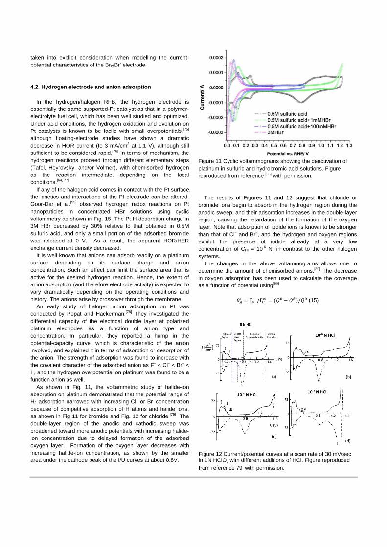
If any of the halogen acid comes in contact with the Pt surface, the kinetics and interactions of the Pt electrode can be altered. Goor-Dar et al.[55] observed hydrogen redox reactions on Pt nanoparticles in concentrated HBr solutions using cyclic voltammetry as shown in Fig. 15. The Pt-H desorption charge in 3M HBr decreased by 30% relative to that obtained in 0.5M sulfuric acid, and only a small portion of the adsorbed bromide was released at 0 V. As a result, the apparent HOR/HER exchange current density decreased.
It is well known that anions can adsorb readily on a platinum surface depending on its surface charge and anion concentration. Such an effect can limit the surface area that is active for the desired hydrogen reaction. Hence, the extent of anion adsorption (and therefore electrode activity) is expected to vary dramatically depending on the operating conditions and history. The anions arise by crossover through the membrane.
An early study of halogen anion adsorption on Pt was conducted by Popat and Hackerman.[78] They investigated the differential capacity of the electrical double layer at polarized platinum electrodes as a function of anion type and concentration. In particular, they reported a hump in the potential-capacity curve, which is characteristic of the anion involved, and explained it in terms of adsorption or desorption of the anion. The strength of adsorption was found to increase with the covalent character of the adsorbed anion as F− < Cl− < Br− < I−, and the hydrogen overpotential on platinum was found to be a function anion as well.
As shown in Fig. 11, the voltammetric study of halide-ion absorption on platinum demonstrated that the potential range of H2 adsorption narrowed with increasing Cl− or Br− concentration because of competitive adsorption of H atoms and halide ions, as shown in Fig 11 for bromide and Fig. 12 for chloride.[79] The double-layer region of the anodic and cathodic sweep was broadened toward more anodic potentials with increasing halide-ion concentration due to delayed formation of the adsorbed oxygen layer. Formation of the oxygen layer decreases with increasing halide-ion concentration, as shown by the smaller area under the cathode peak of the I/U curves at about 0.8V.
Figure 11 Cyclic voltammograms showing the deactivation of platinum in sulfuric and hydrobromic acid solutions. Figure reproduced from reference [55] with permission.
The results of Figures 11 and 12 suggest that chloride or bromide ions begin to absorb in the hydrogen region during the anodic sweep, and their adsorption increases in the double-layer region, causing the retardation of the formation of the oxygen layer. Note that adsorption of iodide ions is known to be stronger than that of Cl− and Br−, and the hydrogen and oxygen regions exhibit the presence of iodide already at a very low concentration of CHI = 10-6 N, in contrast to the other halogen systems.
The changes in the above voltammograms allows one to determine the amount of chemisorbed anions.[80] The decrease in oxygen adsorption has been used to calculate the coverage as a function of potential using[80]
𝜃𝐴′ = Γ𝐴−/Γ𝑂∞ = (𝑄0 − 𝑄𝜃)/𝑄0 (15)
Figure 12 Current/potential curves at a scan rate of 30 mV/sec in 1N HClO4 with different additions of HCl. Figure reproduced from reference 79 with permission.
where Γ𝐴− and Γ𝑂∞ are the areas covered by anion in solution and by oxygen in anion-free supporting electrolyte, respectively, and 𝑄0 is the charge consumed during oxygen adsorption on the electrode in a supporting electrolyte (i.e. no competitive anion adsorption, and thus the effect of adsorbed anion is negligible), and 𝑄𝜃 is the charge consumed in the anion solution (i.e. the oxygen adsorption is affected by the anions competitively adsorbed on the electrode surface). Thus, the difference, 𝑄0 − 𝑄𝜃, indicates sites occupied by anion (Γ𝐴−).
One can also normalize the coverage with respect to the maximum anion coverage (which may be less than complete coverage), using[80]
𝜃𝐴− = Γ𝐴−/Γ𝐴−∞ = (𝑄0 − 𝑄𝜃)/(𝑄0 − 𝑄𝑐) (16)
where Γ𝐴− and Γ𝐴−∞ are the areas adsorbed by anions in the solution and in maximum anion-coverage condition (i.e. limiting coverage), respectively. 𝑄𝑐 is the charge due to oxygen adsorption at the limiting coverage. Thus, 𝑄0 − 𝑄𝑐 indicates the charge related to maximum anion coverage.
From the above analysis,[80] it was determined that the maximum anion coverage on a smooth platinum electrode was 90% of the total adsorption sites capable of absorbing hydrogen and oxygen for iodide, corresponding to a surface concentration of 2 x 10⁻⁹ mol/cm2 if the adsorbed iodide is directly bonded to a single platinum surface atom. For the case of bromide, coverage was limited to only 60% of adsorption sites capable of absorbing oxygen (i.e 1.35 x 10⁻⁹ mol/cm2), due to steric hindrances or repulsion forces. The lowest limiting coverage was found for chloride, at 45 to 50% of oxygen monolayer (1.1 x 10⁻⁹ mol/cm2).
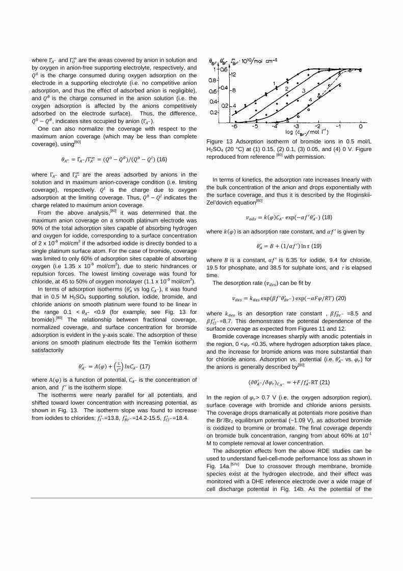
In terms of adsorption isotherms (𝜃𝐴′ vs log 𝐶𝐴−), it was found that in 0.5 M H2SO4 supporting solution, iodide, bromide, and chloride anions on smooth platinum were found to be linear in the range 0.1 < 𝜃𝐴− <0.9 (for example, see Fig. 13 for bromide).[80] The relationship between fractional coverage, normalized coverage, and surface concentration for bromide adsorption is evident in the y-axis scale. The adsorption of these anions on smooth platinum electrode fits the Temkin isotherm satisfactorily
𝜃𝐴−′ = 𝐴(𝜑) + � 1
𝑓′� 𝑙𝑙𝐶𝐴− (17)
where A(φ) is a function of potential, 𝐶𝐴− is the concentration of anion, and 𝑓′ is the isotherm slope.
The isotherms were nearly parallel for all potentials, and shifted toward lower concentration with increasing potential, as shown in Fig. 13. The isotherm slope was found to increase from iodides to chlorides; 𝑓𝐼−′ =13.8, 𝑓𝐵𝐵−′ =14.2-15.5, 𝑓𝐶𝑐−′ =18.4.
Figure 13 Adsorption isotherm of bromide ions in 0.5 mol/L H2SO4 (20 °C) at (1) 0.15, (2) 0.1, (3) 0.05, and (4) 0 V. Figure reproduced from reference [80] with permission.
In terms of kinetics, the adsorption rate increases linearly with the bulk concentration of the anion and drops exponentially with the surface coverage, and thus it is described by the Roginskii-Zel’dovich equation[80]
𝑣𝑎𝑎𝑎 = 𝑘(𝜑)𝐶𝐴− exp(−𝛼𝑓′𝜃𝐴−′ ) (18) where 𝑘(𝜑) is an adsorption rate constant, and 𝛼𝑓′ is given by
𝜃𝐴′ = 𝐵 + (1/𝛼𝑓′) ln 𝜏 (19)
where 𝐵 is a constant, α𝑓′ is 6.35 for iodide, 9.4 for chloride, 19.5 for phosphate, and 38.5 for sulphate ions, and τ is elapsed time.
The desorption rate (𝑣𝑎𝑐𝑎) can be fit by
𝑣𝑎𝑐𝑎 = 𝑘𝑎𝑐𝑎 exp(𝛽𝑓′𝜃𝐵𝐵−′ ) exp(−𝛼𝛼𝜑/𝑅𝑇) (20)
where 𝑘𝑎𝑐𝑎 is an desorption rate constant , 𝛽𝑓𝐵𝐵−′ =8.5 and 𝛽𝑓𝐶𝑐−′ =8.7. This demonstrates the potential dependence of the surface coverage as expected from Figures 11 and 12.
Bromide coverage increases sharply with anodic potentials in the region, 0 <𝜑𝐵 <0.35, where hydrogen adsorption takes place, and the increase for bromide anions was more substantial than for chloride anions. Adsorption vs. potential (i.e. 𝜃𝐴−′ vs. 𝜑𝐵) for the anions is generally described by[80]
(∂𝜃𝐴−′ /𝜕𝜑𝐵)𝐶𝐴− = +𝛼/𝑓𝐴−′ RT (21)
In the region of 𝜑𝐵> 0.7 V (i.e. the oxygen adsorption region), surface coverage with bromide and chloride anions persists. The coverage drops dramatically at potentials more positive than the Br-/Br2 equilibrium potential (~1.09 V), as adsorbed bromide is oxidized to bromine or bromate. The final coverage depends on bromide bulk concentration, ranging from about 60% at 10-1 M to complete removal at lower concentration.
The adsorption effects from the above RDE studies can be used to understand fuel-cell-mode performance loss as shown in Fig. 14a.[57e] Due to crossover through membrane, bromide species exist at the hydrogen electrode, and their effect was monitored with a DHE reference electrode over a wide rnage of cell discharge potential in Fig. 14b. As the potential of the
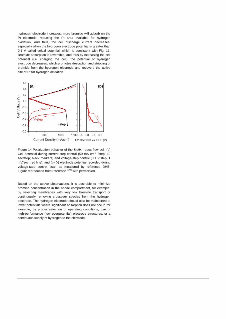
hydrogen electrode increases, more bromide will adsorb on the Pt electrode, reducing the Pt area available for hydrogen oxidation. And thus, the cell discharge current decreases, especially when the hydrogen electrode potential is greater than 0.1 V called crtical potential, which is consistent with Fig. 11. Bromide adsorption is reversible, and thus by increasing the cell potential (i.e. charging the cell), the potential of hydrogen electrode decreases, which promotes desorption and stripping of bromide from the hydrogen electrode and recovers the active site of Pt for hydrogen oxidation.
Figure 14 Polarization behavior of the Br2/H2 redox flow cell. (a) Cell potential during current-step control (50 mA cm-2 /step, 10 sec/step; black markers) and voltage-step control (0.1 V/step, 1 mV/sec; red line), and (b) (-) electrode potential recorded during voltage-step control scan as measured by reference DHE. Figure reproduced from reference [57e] with permission. Based on the above observations, it is desirable to minimize bromine concentration in the anode compartment, for example, by selecting membranes with very low bromine transport or continuously removing crossover species from the hydrogen electrode. The hydrogen electrode should also be maintained at lower potentials where significant adsorption does not occur, for example, by proper selection of operating conditions, use of high-performance (low overpotential) electrode structures, or a continuous supply of hydrogen to the electrode.
5. Membrane
A separator is required to prevent shorting and product or reactant mixing.[81] Several types of membrane separators have been applied to hydrogen/halogen electrochemical system, including perfluorinated sulfonic-acid (PFSA) membrane for H2/Br2 system[5c, 20a, 27, 28b, 37, 39-43, 45, 47-50, 56, 57c, 58a, 58b, 73] and H2/Cl2 system[30, 32-34, 36], nano-porous proton-conducting material,[26b, 52] and phosphoric-acid-doped polybenzimidazole (PBI) membrane.[36b] The vast majority of cells use an ion-conducting membrane, of which Nafion is the most common due to its good transport properties and thermomechanical and chemical stability.
Nafion is a random copolymer of tetrafluoroethylene (TFE) and perfluorovinyl ether containing a functional sulfonic-acid endgroup. Nafion, like most ionomers, has a phase-separated nanostructure wherein the hydrophilic phase is comprised of ions and solvents and the hydrophobic phase is mainly the PTFE backbone responsible for the mechanical stability of the material as shown in Fig. 15. The size and interconnectivity of the hydrophilic domains control the membrane's transport properties (e.g. ionic conductivity, water diffusion, etc.).
In particular, the membrane in a RFB contacts and interacts with the liquid electrolyte containing the reactant species. It is known that Nafion and other ion-conducting polymers dehydrate when in contact with solutions of high ionic strength.[5c, 20a, 21b, 39-
40, 57c, 82] Thus, as the membrane is dehydrated due to this contact, the morphology of it changes, resulting in a decreased proton transport and increased electrostatic potential-energy barrier for anion migration. In this section, we will overview and summarize the research on transport properties of Nafion such as proton conductivity, diffusivity, permeation rate, and electro-osmotic water transport for the hydrogen/halogen system.
5.1. Transport properties of Nafion
5.1.1. Proton conductivity[83] [84]
One of the critical functionalities of the membrane is proton
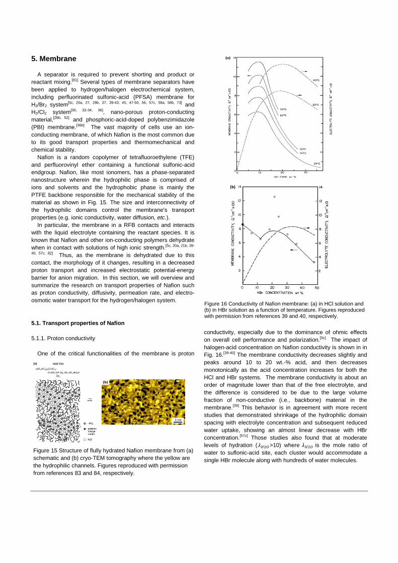
conductivity, especially due to the dominance of ohmic effects on overall cell performance and polarization.[5c] The impact of halogen-acid concentration on Nafion conductivity is shown in in Fig. 16.[39-40] The membrane conductivity decreases slightly and peaks around 10 to 20 wt.-% acid, and then decreases monotonically as the acid concentration increases for both the HCl and HBr systems. The membrane conductivity is about an order of magnitude lower than that of the free electrolyte, and the difference is considered to be due to the large volume fraction of non-conductive (i.e., backbone) material in the membrane.[39] This behavior is in agreement with more recent studies that demonstrated shrinkage of the hydrophilic domain spacing with electrolyte concentration and subsequent reduced water uptake, showing an almost linear decrease with HBr concentration.[57c] Those studies also found that at moderate levels of hydration (𝜆𝐻2𝑂>10) where 𝜆𝐻2𝑂 is the mole ratio of water to suflonic-acid site, each cluster would accommodate a single HBr molecule along with hundreds of water molecules.
Figure 15 Structure of flully hydrated Nafion membrane from (a) schematic and (b) cryo-TEM tomography where the yellow are the hydrophilic channels. Figures reproduced with permission from references 83 and 84, respectively.
Figure 16 Conductivity of Nafion membrane: (a) in HCl solution and (b) in HBr solution as a function of temperature. Figures reproduced with permission from references 39 and 40, respectively.
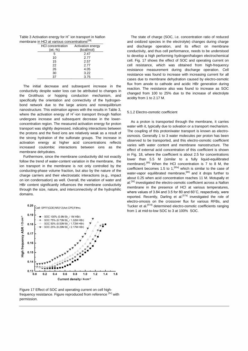
Table 3 Activation energy for H+ ion transport in Nafion membrane in HCl at various concentrations[39]
HCl concentration (wt.-%)
Activation energy (kcal/mol)
5 2.47 10 2.77 15 2.57 22 2.77 26 4.05 30 3.22 37 3.75
The initial decrease and subsequent increase in the
conductivity despite water loss can be attributed to changes in the Grotthuss or hopping conduction mechanism, and specifically the orientation and connectivity of the hydrogen-bond network due to the large anions and nonequilibrium nanostructure. This estimation agrees with the results in Table 3, where the activation energy of H+-ion transport through Nafion undergoes increase and subsequent decrease in the lower-concentration region. The measured activation energy for proton transport was slightly depressed, indicating interactions between the protons and the fixed ions are relatively weak as a result of the strong hydration of the sulfonate groups. The increase in activation energy at higher acid concentrations reflects increased coulombic interactions between ions as the membrane dehydrates.
Furthermore, since the membrane conductivity did not exactly follow the trend of water-content variation in the membrane, the ion transport in the membrane is not only controlled by the conducting-phase volume fraction, but also by the nature of the charge carriers and their electrostatic interactions (e.g., impact on ion condensation) as well. Overall, the variation of water and HBr content significantly influences the membrane conductivity through the size, nature, and interconnectivity of the hydrophilic domains.
Figure 17 Effect of SOC and operating current on cell high-frequency resistance. Figure reproduced from reference [5c] with permission.
The state of charge (SOC, i.e. concentration ratio of reduced and oxidized species in the electrolyte) changes during charge and discharge operation, and its effect on membrane conductivity, and thus cell performance, needs to be understood to develop a high performing hydrogen/halogen electrochemical cell. Fig. 17 shows the effect of SOC and operating current on cell resistance, which was obtained from high-frequency resistance measurement during discharge operation. Cell resistance was found to increase with increasing current for all cases due to membrane dehydration caused by electro-osmotic flux from anode to cathode and acidic HBr generation during reaction. The resistance also was found to increase as SOC changed from 100 to 25% due to the increase of electrolyte acidity from 1 to 2.17 M.
5.1.2 Electro-osmotic coefficient
As a proton is transported through the membrane, it carries water with it, typically due to solvation or a transport mechanism. The coupling of this proton/water transport is known as electro-osmosis. Generally 1 to 3 water molecules per proton has been observed to be transported, and this electro-osmotic coefficient varies with water content and membrane nanostructure. The effect of external acid concentration of this coefficient is shown in Fig. 18, where the coefficient is about 2.5 for concentrations lower than 5.5 M (similar to a fully liquid-equilibrated membrane).[85] When the HCl concentration is 7 to 8 M, the coefficient becomes 1.5 to 1,[65a] which is similar to the case of water-vapor equilibrated membrane,[86] and it drops further to about 0.25 when acid concentration reaches 11 M. Motupally et al.[34] investigated the electro-osmotic coefficient across a Nafion membrane in the presence of HCl at various temperatures, where values of 3.84 and 3.5 for 80 and 60˚C, respectively, were reported. Recently, Darling et al.[57a] investigated the role of electro-omosis on the crossover flux for various RFBs, and Tucker et al.[57d] determined electro-osmotic coefficients ranging from 1 at mid-to-low SOC to 3 at 100% SOC.
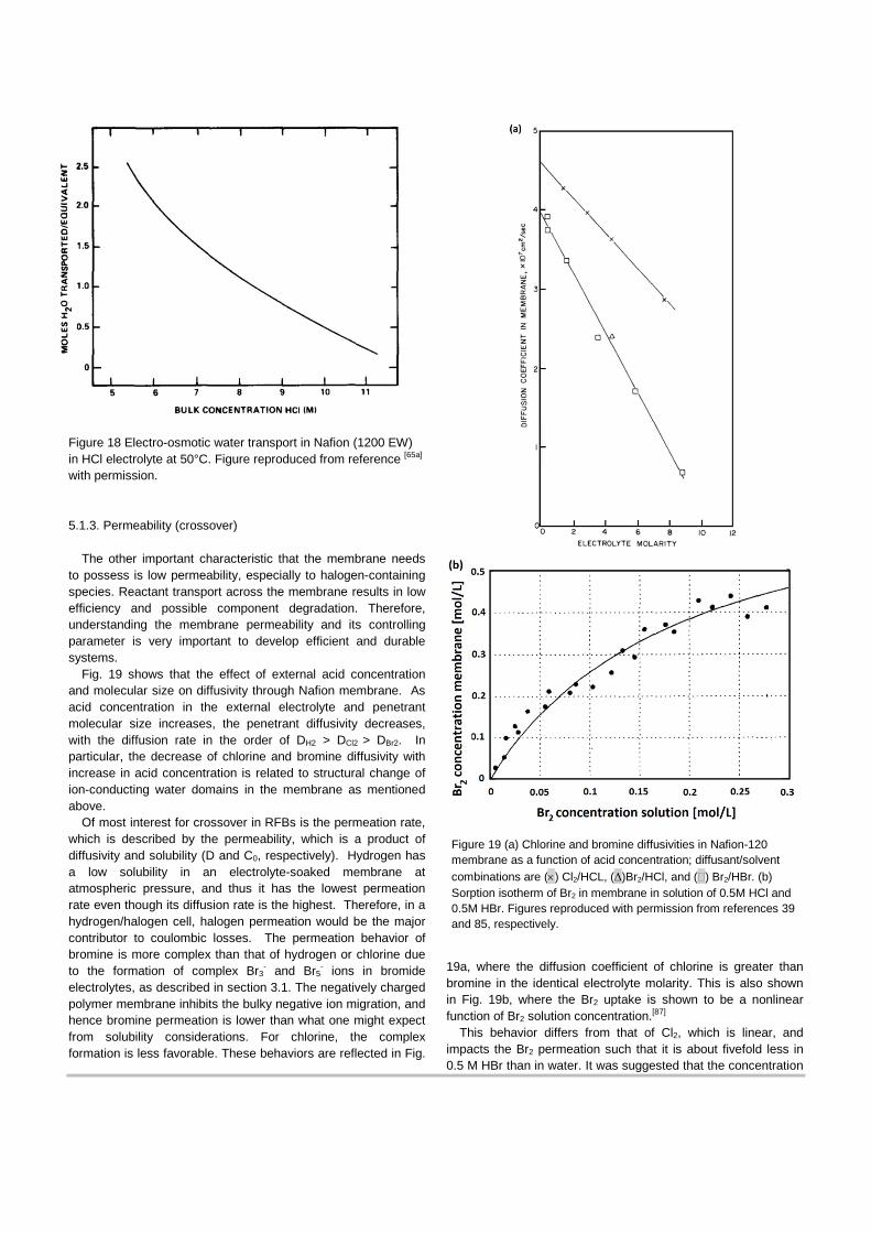
Figure 18 Electro-osmotic water transport in Nafion (1200 EW) in HCl electrolyte at 50°C. Figure reproduced from reference [65a] with permission.
5.1.3. Permeability (crossover)
The other important characteristic that the membrane needs to possess is low permeability, especially to halogen-containing species. Reactant transport across the membrane results in low efficiency and possible component degradation. Therefore, understanding the membrane permeability and its controlling parameter is very important to develop efficient and durable systems.
Fig. 19 shows that the effect of external acid concentration and molecular size on diffusivity through Nafion membrane. As acid concentration in the external electrolyte and penetrant molecular size increases, the penetrant diffusivity decreases, with the diffusion rate in the order of DH2 > DCl2 > DBr2. In particular, the decrease of chlorine and bromine diffusivity with increase in acid concentration is related to structural change of ion-conducting water domains in the membrane as mentioned above.
Of most interest for crossover in RFBs is the permeation rate, which is described by the permeability, which is a product of diffusivity and solubility (D and C0, respectively). Hydrogen has a low solubility in an electrolyte-soaked membrane at atmospheric pressure, and thus it has the lowest permeation rate even though its diffusion rate is the highest. Therefore, in a hydrogen/halogen cell, halogen permeation would be the major contributor to coulombic losses. The permeation behavior of bromine is more complex than that of hydrogen or chlorine due to the formation of complex Br3
- and Br5- ions in bromide
electrolytes, as described in section 3.1. The negatively charged polymer membrane inhibits the bulky negative ion migration, and hence bromine permeation is lower than what one might expect from solubility considerations. For chlorine, the complex formation is less favorable. These behaviors are reflected in Fig.
19a, where the diffusion coefficient of chlorine is greater than bromine in the identical electrolyte molarity. This is also shown in Fig. 19b, where the Br2 uptake is shown to be a nonlinear function of Br2 solution concentration.[87]
This behavior differs from that of Cl2, which is linear, and impacts the Br2 permeation such that it is about fivefold less in 0.5 M HBr than in water. It was suggested that the concentration
Figure 19 (a) Chlorine and bromine diffusivities in Nafion-120 membrane as a function of acid concentration; diffusant/solvent combinations are (×) Cl2/HCL, (∆)Br2/HCl, and (�) Br2/HBr. (b) Sorption isotherm of Br2 in membrane in solution of 0.5M HCl and 0.5M HBr. Figures reproduced with permission from references 39 and 85, respectively.
of Br- ion has to be chosen as high as possible to reduce crossover, although this impacts the membrane conductivity as discussed in section 5.1.1; an optimum concentration is required, wherein the HBr concentration should be at least equal to that of Br2.
As Br2 complexes with HBr, migration forces can also drive its crossover. In fact, halide crossover could also be a critical source of coulombic inefficiency. Such issues have recently been investigated,[57a, 57d] with findings showing the impact and importance of ionic-species crossover on cell efficiency. Similar to the above concentration-dependent studies, one must also be cognizant that crossover will be a function of charge direction as well as SOC, which varies during operation. The impact of current density, current direction, and SOC on water and bromine crossover flux was examined in detail for a boiled NR212 membrane.[57d] It was found that significant water and bromine flux occurs during charge, and is a strong function of current density, as electro-osmosis dominates over diffusion.[57a] During discharge, electro-osmosis essentially balances diffusion, leading to negligible crossover. The bromine-per-water coefficient decreases with SOC and current density, attributed to higher exclusion of Br-complexes from the membrane, relative to bromide.
5.1.4 Impact of equivalent weight and pretreatment
As noted throughout the discussion above, membrane ion-exchange capacity and pretreatment can impact the transport properties of the membrane. It is well known that pretreatment alters both the nanostructure and sorption behavior of water-swollen Nafion membranes,[88] which is also a function of its thermal history.[88b] Thus, when a pretreated Nafion membrane is equilibrated in HBr solution, it’s overall electrolyte-uptake capacity improves, resulting in larger domain spacing and higher conductivity as shown in Table 4.
Table 4 Effect of thermal history on membrane in-plane conductivity at room temperature.[40]
Treatment Electrolyte content Conductivity in 24%
HBr, Ω-1cm-1
Standard treatment 25.9 0.098 Untreated 17.8 0.076
Dried in vac. At 140°C 11.4 0.035
In terms of equivalent weight (EW), which is the inverse of ion-exchange capacity, this also is expected to impact conductivity since the effective concentration of charge carriers decreases with increasing EW due to a higher fraction of backbone moieties. In general, lower EW membranes tend to have better low-humidity performance due to higher moisture uptake, but suffer increased swelling in moist environments due to loss of mechanical reinforcement.[41] It is also clear that lower EW is better, although one cannot go much below 900 g mol-1
due to stability concerns; research to find the optimal EW is still required.[27]
Similar trends with EW have been observed at high charge current, where both diffusion and electro-osmosis contribute to bromine crossover.[57d] Thicker membranes and higher EWs achieved lower bromine flux. These trends were overshadowed, however, by the large increase in bromine flux for membranes that were pretreated by soaking in hot or boiling water prior to cell assembly. It was also noted that the hydration state of the membrane during cell assembly has a significant impact on subsequent transport properties.
5.1.5. Effect of crossover (self-discharge) on cell performance
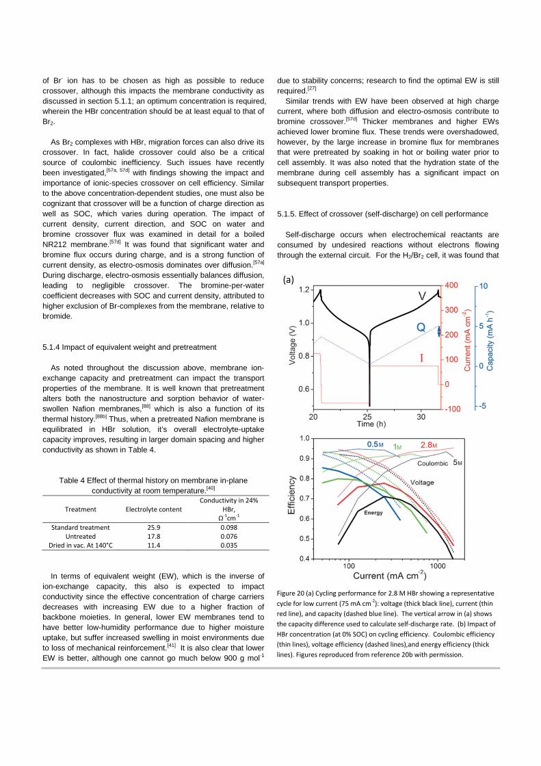
Self-discharge occurs when electrochemical reactants are consumed by undesired reactions without electrons flowing through the external circuit. For the H2/Br2 cell, it was found that
Figure 20 (a) Cycling performance for 2.8 M HBr showing a representative cycle for low current (75 mA cm-2): voltage (thick black line), current (thin red line), and capacity (dashed blue line). The vertical arrow in (a) shows the capacity difference used to calculate self-discharge rate. (b) Impact of HBr concentration (at 0% SOC) on cycling efficiency. Coulombic efficiency (thin lines), voltage efficiency (dashed lines),and energy efficiency (thick lines). Figures reproduced from reference 20b with permission.
crossover of bromine species to the anode resulted in a significant self-discharge current.[20b] After crossover, reduction of Br2 to Br- occurs at the anode. The Br- is returned to the positive electrode tank either by transport through the membrane or external capture of liquid from the negative-electrode exhaust. The overall result is a reduction of bromine species in the cathode tank without generation of useful current. The self-discharge rate can be determined from cycling data, as the difference between charge and discharge capacity per cell area divided by the cycle time, as shown in Fig. 20a for various electrolyte concentrations and hydrogen pressures. At high bromine concentration and low faradaic current, the resulting coulombic inefficiency during cycling can be significant and constrains the overall energy efficiency of the system as shown in Fig. 20b.
5.2. Other membrane types
As described so far, PFSA membranes are the most commonly used ones for hydrogen/halogen RFBs since they have relatively low ionic resistance and high mechanical and chemical durability. However, these membranes can be costly. More advanced RFB membranes are being investigated and synthesized although a detailed review of them is beyond the scope of this article. Of note for hydrogen/halogen systems, are membranes that minimize the amount of Nafion by using an inactive filler.[89] For example, Pintauro and coworkers have developed nanospun Nafion membranes with cospun PVDF, which allows for lower crossover but still good conductivity and a lower usage of Nafion.
Another approach is to use a microporous separator instead of a membrane.[52, 90] In this case, a composite membrane (NP-PCM) that consists of nano-sized silica powder and PVDF binder with typical pore size of 1.5 nm can be used. The hydrophilic separator is wetted by electrolyte and thus membrane-dehydration issue affected by external strong acid, which is the critical issue in Nafion-type membranes, can be mitigated. However, although the NP-PCM membrane is more hydrophilic than Nafion and its conductivity is higher, it may cause extra bromine, and bromide-ion complexes to crossover to the negative electrode, which will lead to possible Pt catalyst degradation and system efficiency associated with self-discharge. In addition, care must be taken for pressurized systems to keep the cell balanced compared to PFSA membranes that can withstand pressure differentials.
6. Flow field
Mass transport of reactant to the reaction site depends on both convection and diffusion. The former is typically more efficient and greatly impacted by flowfield architectures, with better penetration coming at the cost of increased pressure drop. For the cell, the diffusivity of the halogen species in the liquid phase is about two orders of magnitude lower than that of hydrogen in the gas phase,[91] suggesting the halogen (+) side will dominate mass-transport limitations. A common and efficient method to alleviate mass-transport limitations is to utilize a flowfield geometry that induces forced convection in the electrode.
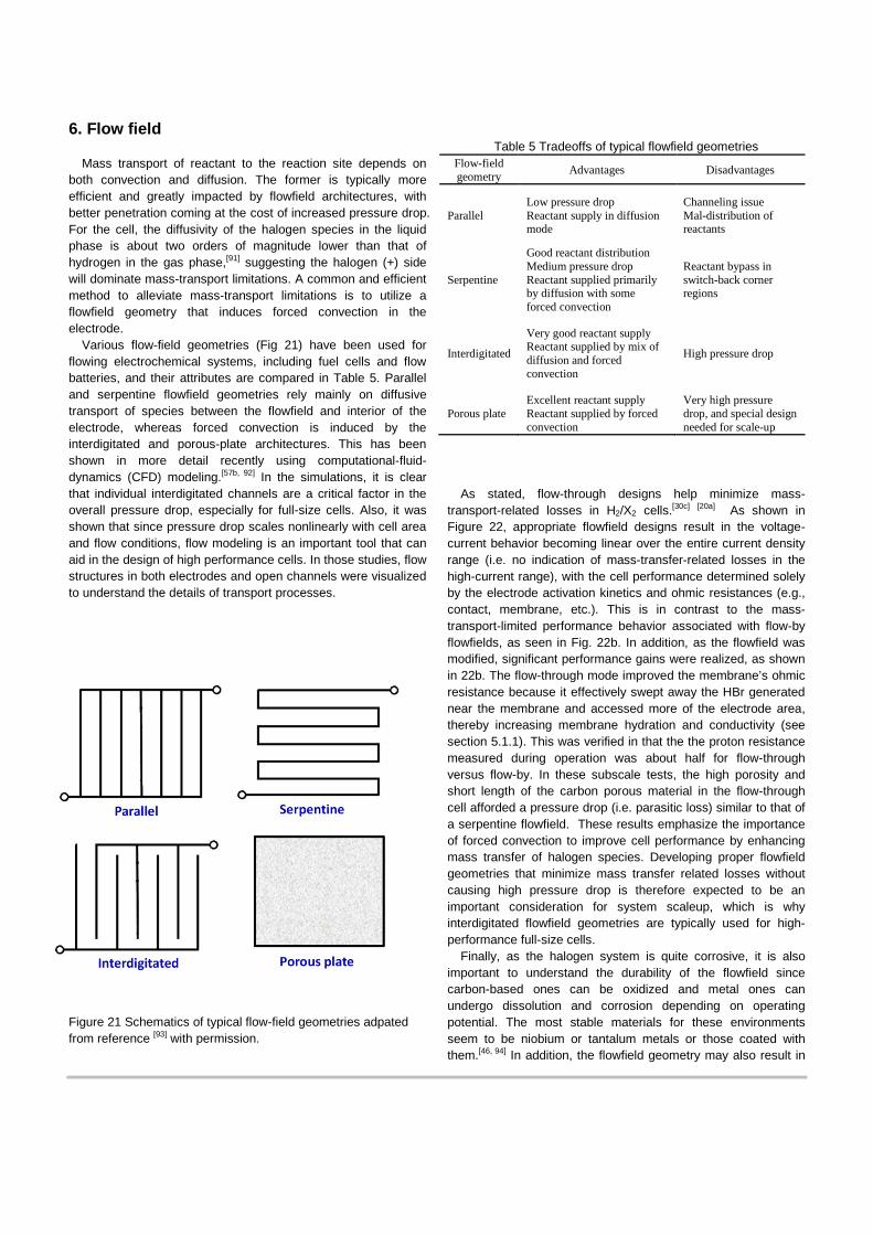
Various flow-field geometries (Fig 21) have been used for flowing electrochemical systems, including fuel cells and flow batteries, and their attributes are compared in Table 5. Parallel and serpentine flowfield geometries rely mainly on diffusive transport of species between the flowfield and interior of the electrode, whereas forced convection is induced by the interdigitated and porous-plate architectures. This has been shown in more detail recently using computational-fluid-dynamics (CFD) modeling.[57b, 92] In the simulations, it is clear that individual interdigitated channels are a critical factor in the overall pressure drop, especially for full-size cells. Also, it was shown that since pressure drop scales nonlinearly with cell area and flow conditions, flow modeling is an important tool that can aid in the design of high performance cells. In those studies, flow structures in both electrodes and open channels were visualized to understand the details of transport processes.
Figure 21 Schematics of typical flow-field geometries adpated from reference [93] with permission.
Table 5 Tradeoffs of typical flowfield geometries
Flow-field geometry Advantages Disadvantages
Parallel Low pressure drop Reactant supply in diffusion mode
Channeling issue Mal-distribution of reactants
Serpentine
Good reactant distribution Medium pressure drop Reactant supplied primarily by diffusion with some forced convection
Reactant bypass in switch-back corner regions
Interdigitated
Very good reactant supply Reactant supplied by mix of diffusion and forced convection
High pressure drop
Porous plate Excellent reactant supply Reactant supplied by forced convection
Very high pressure drop, and special design needed for scale-up
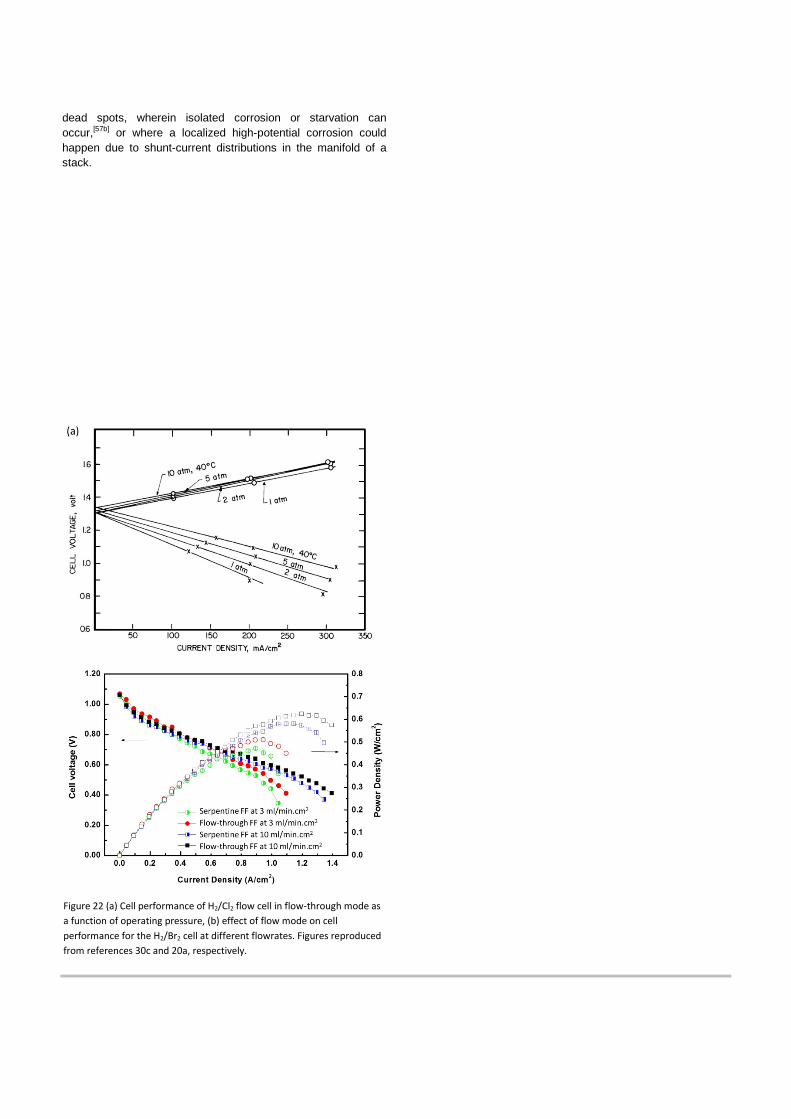
As stated, flow-through designs help minimize mass-
transport-related losses in H2/X2 cells.[30c] [20a] As shown in Figure 22, appropriate flowfield designs result in the voltage-current behavior becoming linear over the entire current density range (i.e. no indication of mass-transfer-related losses in the high-current range), with the cell performance determined solely by the electrode activation kinetics and ohmic resistances (e.g., contact, membrane, etc.). This is in contrast to the mass-transport-limited performance behavior associated with flow-by flowfields, as seen in Fig. 22b. In addition, as the flowfield was modified, significant performance gains were realized, as shown in 22b. The flow-through mode improved the membrane’s ohmic resistance because it effectively swept away the HBr generated near the membrane and accessed more of the electrode area, thereby increasing membrane hydration and conductivity (see section 5.1.1). This was verified in that the the proton resistance measured during operation was about half for flow-through versus flow-by. In these subscale tests, the high porosity and short length of the carbon porous material in the flow-through cell afforded a pressure drop (i.e. parasitic loss) similar to that of a serpentine flowfield. These results emphasize the importance of forced convection to improve cell performance by enhancing mass transfer of halogen species. Developing proper flowfield geometries that minimize mass transfer related losses without causing high pressure drop is therefore expected to be an important consideration for system scaleup, which is why interdigitated flowfield geometries are typically used for high-performance full-size cells.
Finally, as the halogen system is quite corrosive, it is also important to understand the durability of the flowfield since carbon-based ones can be oxidized and metal ones can undergo dissolution and corrosion depending on operating potential. The most stable materials for these environments seem to be niobium or tantalum metals or those coated with them.[46, 94] In addition, the flowfield geometry may also result in
dead spots, wherein isolated corrosion or starvation can occur,[57b] or where a localized high-potential corrosion could happen due to shunt-current distributions in the manifold of a stack.
Figure 22 (a) Cell performance of H2/Cl2 flow cell in flow-through mode as a function of operating pressure, (b) effect of flow mode on cell performance for the H2/Br2 cell at different flowrates. Figures reproduced from references 30c and 20a, respectively.
7. Durability of the H2/Br2 cell
Most of the studies in the literature have not focused on durability and lifetime (with typical satisfactory lifetime on the order of 10’s of hours deemed sufficient for performance evaluation). Of the various H2/X2 cells, H2/Br2 has had the most significant lifetime studies. In this section, we review lifetime and durability issues of the H2/Br2 cell, although the findings should be similar for other H2/X2 cells due to their inherently similar chemical nature.
7.1. Material compatibility
Halogens are highly corrosive chemicals that are known to corrode most materials. Specific materials have been identified, however, that are suitable for cell and balance-fo-plant construction. Several technical reports assessed candidate materials for the operating conditions of the hydrogen-halogen cell, typically by analyzing degradation after ex-situ soaking in concentrated electrolyte solution such as shown in Table 6. [46] [47] [26b, 37]
For system components for wet bromine, materials including glass, glass-lined metals, tantalum, Teflon, Kalrez, Halar, Kynar, graphite, and carbon materials such as graphite felts and RVC were reported to be compatible. For pipes, pumps, and valves operated in 48 wt % HBr aqueous solution, materials such as carbon steel lined with Teflon, Kynar, high density polyethylene (HDPE) and poly propylene (PP) are stable and acceptable. Viton, Kalrez, ethylene propylene diene monomer (EPDM), neoprene, HDPE and PP, and fluoropolymers such as Teflon and polyvinylidene fluoride (PVDF) are satisfactory for gaskets and hoses. Tantalum and niobium metals, and perhaps graphite (if sealed), are satisfactory for bipolar plates as mentioned in section 6. Similar materials are compatable with other halogen chemistries, although for chlorine one must additionally be concerned about pressurization issues for the tanks due to the high vapor pressure. For fluorine, it is known that it can coat and hydrophobize various components, thereby resulting in changes to wetting and mass-transport behavior.[95]
Selection of electrocatalysts is challenging, as the material must be highly active for hydrogen or bromine reactions, yet stable in the presence of these same aggressive chemicals. Pt-Ir alloy, and Ir or Ir-oxide were reported to be suitable hydrogen and bromine electrode materials, respectively.[96]
Schuetz and coworkers[97] screened possible electrocatalyst materials for stability including noble metals (platnum and iridium), and metal alloys such as tantalum, molybdenum, and zirconium. Tantalum was the only one having high corrosion resistance, but it also showed high bromine overpotential if used as an electrocatalyst. Bulk Pt showed excellent electrochemical behavior and corroded slowly. The corrosion rate of Pt in Br2/ HBr solution at 373K was found to be 8.07 × 10⁻⁴ mg/cm2s. The finely divided form of noble metals such as Pt black and Ir black were, however, corroded rapidly. The only material which proved satisfactory for technical application was graphite, and the high hydrogen overvoltage of graphite could be reduced to a large
extent by adding small amounts of Pd or Pt salts directly to the electrolyte. Recent efforts typically use carbon for the bromine electrode and Pt/C for the hydrogen electrode,[5c, 20a, 57e] although it is recognized that development of bromine-tolerant alternatives to Pt is still required.[5d, 58d, 58e]
Table 6 Aging test results for different materials and ageing conditions[46]
Aging: 30 days in 4 M Br2/6M HBr at 80˚C
Aging: 6 months in 4 M Br2/6M HBr at 80˚C
Materials Observations Materials Observations
Polyethylene Soft, orange color RVC No change
Vitreous carbon
Cracked on the surface Titanium Black color
Coated vitreous carbon
Cracked on the surface Graphite No change
Viton rubber Gray color Thornel Brittle Carbon No change Carbon No change
Graphite No change Vitreous carbon Swollen, brittle
Titanium No change Coated vitreous carbon
Swollen, brittle
Tantalum No change Tantalum No change Polysulfone Decomposed Carbon felt No change Karbated graphite Brittle
7.2. Platinum dissolution and deactivation
When bromine species reach the Pt catalyst in the negative electrode, they will be immediately reduced via Eq. 2 as long as sufficient hydrogen is fed to maintain a low anode potential. However, if the hydrogen supply to the negative side is insufficient, then a mixed potential will be generated, causing the local potential to exceed the bromide adsorption and Pt dissolution potentials (see Fig. 14), risking Pt poisoning and dissolution. Therefore, sufficient hydrogen concentration must be maintained in the negative electrode for the entire service life of the cell. This has also been shown in that a cathodically protected cell demonstrates a one to to order of maginitude decrease in the rate of Pt dissolution in 48 wt-% HBr.[20b] This latter study also highlights that although Br2 can cause rapid dissolution by increasing the Pt potential, the adsorption of Br- (discussed in detail in Section 4.2) can also corrode Pt.
The results suggest two related strategies for avoiding Pt corrosion in an operating system: maintain the presence of hydrogen at the Pt electrode, and in the case of hydrogen supply failure, use a small cathodic-protection current to generate hydrogen at the electrode. Another strategy is to develop alternative materials that are tolerant to bromine and bromide. PtIrNx has been shown to be dramatically more stable than Pt in the presence of bromine, without sacrificing HOR/HER catalysis,[5d] as has various transition-metal sulfide compounds.[58d]
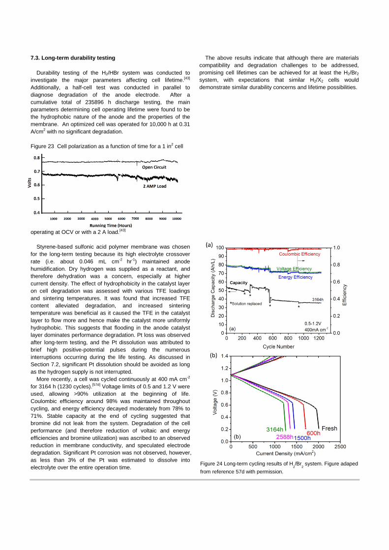
7.3. Long-term durability testing
Durability testing of the H2/HBr system was conducted to investigate the major parameters affecting cell lifetime.[43] Additionally, a half-cell test was conducted in parallel to diagnose degradation of the anode electrode. After a cumulative total of 235896 h discharge testing, the main parameters determining cell operating lifetime were found to be the hydrophobic nature of the anode and the properties of the membrane. An optimized cell was operated for 10,000 h at 0.31 A/cm2 with no significant degradation. Figure 23 Cell polarization as a function of time for a 1 in2 cell
operating at OCV or with a 2 A load.[43]
Styrene-based sulfonic acid polymer membrane was chosen for the long-term testing because its high electrolyte crossover rate (i.e. about 0.046 mL cm-2 hr-1) maintained anode humidification. Dry hydrogen was supplied as a reactant, and therefore dehydration was a concern, especially at higher current density. The effect of hydrophobicity in the catalyst layer on cell degradation was assessed with various TFE loadings and sintering temperatures. It was found that increased TFE content alleviated degradation, and increased sintering temperature was beneficial as it caused the TFE in the catalyst layer to flow more and hence make the catalyst more uniformly hydrophobic. This suggests that flooding in the anode catalyst layer dominates performance degradation. Pt loss was observed after long-term testing, and the Pt dissolution was attributed to brief high positive-potential pulses during the numerous interruptions occurring during the life testing. As discussed in Section 7.2, significant Pt dissolution should be avoided as long as the hydrogen supply is not interrupted.
More recently, a cell was cycled continuously at 400 mA cm-2 for 3164 h (1230 cycles).[57d] Voltage limits of 0.5 and 1.2 V were used, allowing >90% utilization at the beginning of life. Coulombic efficiency around 98% was maintained throughout cycling, and energy efficiency decayed moderately from 78% to 71%. Stable capacity at the end of cycling suggested that bromine did not leak from the system. Degradation of the cell performance (and therefore reduction of voltaic and energy efficiencies and bromine utilization) was ascribed to an observed reduction in membrane conductivity, and speculated electrode degradation. Significant Pt corrosion was not observed, however, as less than 3% of the Pt was estimated to dissolve into electrolyte over the entire operation time.
The above results indicate that although there are materials compatibility and degradation challenges to be addressed, promising cell lifetimes can be achieved for at least the H2/Br2 system, with expectations that similar H2/X2 cells would demonstrate similar durability concerns and lifetime possibilities.
Figure 24 Long-term cycling results of H2/Br
2 system. Figure adaped
from reference 57d with permission.
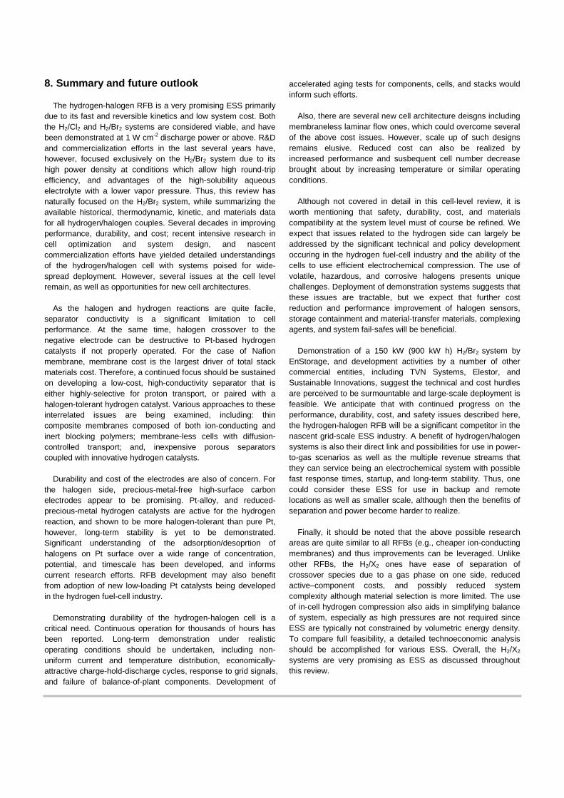
8. Summary and future outlook
The hydrogen-halogen RFB is a very promising ESS primarily due to its fast and reversible kinetics and low system cost. Both the H2/Cl2 and H2/Br2 systems are considered viable, and have been demonstrated at 1 W cm-2 discharge power or above. R&D and commercialization efforts in the last several years have, however, focused exclusively on the H2/Br2 system due to its high power density at conditions which allow high round-trip efficiency, and advantages of the high-solubility aqueous electrolyte with a lower vapor pressure. Thus, this review has naturally focused on the H2/Br2 system, while summarizing the available historical, thermodynamic, kinetic, and materials data for all hydrogen/halogen couples. Several decades in improving performance, durability, and cost; recent intensive research in cell optimization and system design, and nascent commercialization efforts have yielded detailed understandings of the hydrogen/halogen cell with systems poised for wide-spread deployment. However, several issues at the cell level remain, as well as opportunities for new cell architectures.
As the halogen and hydrogen reactions are quite facile,
separator conductivity is a significant limitation to cell performance. At the same time, halogen crossover to the negative electrode can be destructive to Pt-based hydrogen catalysts if not properly operated. For the case of Nafion membrane, membrane cost is the largest driver of total stack materials cost. Therefore, a continued focus should be sustained on developing a low-cost, high-conductivity separator that is either highly-selective for proton transport, or paired with a halogen-tolerant hydrogen catalyst. Various approaches to these interrelated issues are being examined, including: thin composite membranes composed of both ion-conducting and inert blocking polymers; membrane-less cells with diffusion-controlled transport; and, inexpensive porous separators coupled with innovative hydrogen catalysts.
Durability and cost of the electrodes are also of concern. For
the halogen side, precious-metal-free high-surface carbon electrodes appear to be promising. Pt-alloy, and reduced-precious-metal hydrogen catalysts are active for the hydrogen reaction, and shown to be more halogen-tolerant than pure Pt, however, long-term stability is yet to be demonstrated. Significant understanding of the adsorption/desoprtion of halogens on Pt surface over a wide range of concentration, potential, and timescale has been developed, and informs current research efforts. RFB development may also benefit from adoption of new low-loading Pt catalysts being developed in the hydrogen fuel-cell industry.
Demonstrating durability of the hydrogen-halogen cell is a
critical need. Continuous operation for thousands of hours has been reported. Long-term demonstration under realistic operating conditions should be undertaken, including non-uniform current and temperature distribution, economically-attractive charge-hold-discharge cycles, response to grid signals, and failure of balance-of-plant components. Development of
accelerated aging tests for components, cells, and stacks would inform such efforts.
Also, there are several new cell architecture deisgns including
membraneless laminar flow ones, which could overcome several of the above cost issues. However, scale up of such designs remains elusive. Reduced cost can also be realized by increased performance and susbequent cell number decrease brought about by increasing temperature or similar operating conditions.
Although not covered in detail in this cell-level review, it is
worth mentioning that safety, durability, cost, and materials compatibility at the system level must of course be refined. We expect that issues related to the hydrogen side can largely be addressed by the significant technical and policy development occuring in the hydrogen fuel-cell industry and the ability of the cells to use efficient electrochemical compression. The use of volatile, hazardous, and corrosive halogens presents unique challenges. Deployment of demonstration systems suggests that these issues are tractable, but we expect that further cost reduction and performance improvement of halogen sensors, storage containment and material-transfer materials, complexing agents, and system fail-safes will be beneficial.
Demonstration of a 150 kW (900 kW h) H2/Br2 system by
EnStorage, and development activities by a number of other commercial entities, including TVN Systems, Elestor, and Sustainable Innovations, suggest the technical and cost hurdles are perceived to be surmountable and large-scale deployment is feasible. We anticipate that with continued progress on the performance, durability, cost, and safety issues described here, the hydrogen-halogen RFB will be a significant competitor in the nascent grid-scale ESS industry. A benefit of hydrogen/halogen systems is also their direct link and possibilities for use in power-to-gas scenarios as well as the multiple revenue streams that they can service being an electrochemical system with possible fast response times, startup, and long-term stability. Thus, one could consider these ESS for use in backup and remote locations as well as smaller scale, although then the benefits of separation and power become harder to realize.
Finally, it should be noted that the above possible research
areas are quite similar to all RFBs (e.g., cheaper ion-conducting membranes) and thus improvements can be leveraged. Unlike other RFBs, the H2/X2 ones have ease of separation of crossover species due to a gas phase on one side, reduced active–component costs, and possibly reduced system complexity although material selection is more limited. The use of in-cell hydrogen compression also aids in simplifying balance of system, especially as high pressures are not required since ESS are typically not constrained by volumetric energy density. To compare full feasibility, a detailed technoeconomic analysis should be accomplished for various ESS. Overall, the H2/X2 systems are very promising as ESS as discussed throughout this review.
Acknowledgements
This work was funded by Advanced Research Projects Agency-Energy (ARPA-E) of the U.S. Department of Energy (contract no. DE-AC02-05CH11231) with cost share provided by Robert Bosch LLC. and TVN Systems, Inc.
Keywords: Hydrogen-halogen flow battery, Energy storage, redox batteries, progress, review.
[1] D. Hostick, D. B. Belzer, S. W. Hadley, T. Markel, C. Marnay, M. Kintner-Meyer, End-Use Electricity Demand. Vol. 3 of Renewable Electricity Futures Study, NREL/TP-6A20-52409-3, 2012.
[2] Z. Yang, J. Zhang, M. C. W. Kintner-Meyer, X. Lu, D. Choi, J. P. Lemmon, J. Liu, Chem Rev 2011, 111, 3577-3613.
[3] D. O. Energy, ARPA-E Grid-Scale Rampable Intermittent Dispatchable Storage (GRIDS) FOA, 2010.
[4] aM. L. Perry, A. Z. Weber, J. Electrochem. Soc. 2016, 163, A5064-A5067; bG. L. Soloveichik, Chem Rev 2015, in press; cG. L. Soloveichik, Annu Rev Chem Biomol 2011, 2, 503-527.
[5] aJ. Rugolo, M. J. Aziz, Ener. Env. Sci 2012, 5, 7151-7160; bN. Singh, E. W. McFarland, J Power Sources 2015, 288, 187-198; cK. T. Cho, P. Albertus, V. Battaglia, A. Kojic, V. Srinivasan, A. Z. Weber, Energy Technology 2013, 1, 596-608; dG. Lin, P. Y. Chong, V. Yarlagadd, T. V. Nguyen, R. J. Wycisk, P. N. Pintauro, M. Bates, S. Mukerjee, M. C. Tucker, A. Z. Weber, J. Electrochem. Soc. 2016, 163, A5049-A5056.
[6] P. Leung, X. Li, C. Ponce de Leon, L. Berlouis, C. T. J. Low, F. C. Walsh, Rsc Adv 2012.
[7] P. S. Fedkiw, R. W. Watts, J. Electrochem. Soc. 1984, 131, 701-709.
[8] M. Skyllas-Kazacos, M. Rychcik, R. G. Robins, A. G. Fane, M. A. Green, J. Electrochem. Soc. 1986, 133, 1057-1058.
[9] M. Skyllas-Kazacos, J Power Sources 2003, 124, 299-302. [10] W. Wang, S. Kim, B. Chen, Z. Nie, J. Zhang, G.-G. Xia, L. Li, Z.
Yang, Ener. Env. Sci 2011, 4. [11] B. Fang, S. Iwasa, Y. Wei, T. Arai, M. Kumagai, Electrochim Acta
2002, 47, 3971-3976. [12] F.-Q. Xue, Y.-L. Wang, W.-H. Wang, X.-D. Wang, Electrochim Acta
2008, 53, 6636-6642. [13] R. G. A. Wills, J. Collins, D. Stratton-Campbell, C. T. J. Low, D.
Pletcher, F. C. Walsh, J Appl Electrochem 2010, 40, 955-965. [14] Y. Ito, M. Nyce, R. Plivelich, M. Klein, D. Steingart, S. Banerjee, J
Power Sources 2011, 196, 2340-2345. [15] B. Sawyer, G. Suppes, M. Gordon, M. Heidlage, J Appl
Electrochem 2011, 41, 543-550. [16] J. Jorné, J. T. Kim, D. Kralik, J Appl Electrochem 1979, 9, 573-579. [17] H. S. Lim, A. M. Lackner, R. C. Knechtli, J. Electrochem. Soc.
1977, 124, 1154-1157. [18] P. K. Leung, C. Ponce de León, F. C. Walsh, Electrochem
Commun 2011, 13, 770-773. [19] M. Duduta, B. Ho, V. C. Wood, P. Limthongkul, V. E. Brunini, W. C.
Carter, Y.-M. Chiang, Adv. Ener. Mater. 2011, 1, 511-516. [20] aK. T. Cho, P. Ridgway, A. Z. Weber, S. Haussener, V. Battaglia,
V. Srinivasan, J. Electrochem. Soc. 2012, 159, A1806-A1815; bK. T. Cho, M. C. Tucker, M. Ding, P. Ridgway, V. Battaglia, V. Srinivasan, A. Z. Weber, ChemPlusChem 2015, 80, 402; cJ. Rugolo, B. Huskinson, M. J. Aziz, J. Electrochem. Soc. 2011, 159, B133-B144; dB. Huskinson, J. Rugolo, S. K. Mondal, M. J. Aziz, Ener. Env. Sci 2012, 5, 8690-8698.
[21] aM. Tucker, V. Srinivasan, P. Ross, A. Weber, J Appl Electrochem 2013, 43, 637-644; bM. C. Tucker, K. T. Cho, A. Z. Weber, J Power Sources 2014, 245, 691-697.
[22] aA. Z. Weber, M. M. Mench, J. P. Meyers, P. N. Ross, J. T. Gostick, Q. H. Liu, J Appl Electrochem 2011, 41, 1137-1164; bA. Parasuraman, T. M. Lim, C. Menictas, M. Skyllas-Kazacos, Electrochim Acta 2013, 101, 27-40; cS. H. Shin, S. H. Yun, S. H. Moon, Rsc Adv 2013, 3, 9095-9116.
[23] T. V. Nguyen, V. Yarlagadda, G. Lin, G. Weng, V. Li, K. Chan, ECS Transactions 2014, 58, 29-35.
[24] M. Pourbaix, Atlas of electrochemical equilibria in aqueous solutions, 2nd ed., National Association of Corrosion Engineers, Houston, TX, 1974.
[25] aH. Groult, J. Fluorine Chem. 2003, 119, 173-189; bC. P. Jacobson, S. J. Visco, L. C. De Jonghe, C. I. Stefan, US7090752 B2, 2006.
[26] aY. V. Tolmachev, Russ J Electrochem+ 2014, 50, 301-316; bE. Peled, A. Blum, M. Goor, in Encyclopedia of Electrochemical Power Sources (Ed.: J. Garche), Elsevier, Amsterdam, 2009, pp. 182-191.
[27] E. N. Balko, J Appl Electrochem 1981, 11, 91-102. [28] aT. M. Molter, A. B. LaConti, United Technologies Corporation, US,
1989; bF. Mitlitsky, B. Myers, A. H. Weisberg, Energ Fuel 1998, 12, 56-71.
[29] S. Yoshizawa, Z. Takehara, Y. Ito, Y. Nakanishi, Y. Koyama, Journal of Applied Electrochemistry, 4, 81-85.
[30] aE. Gileadi, S. Srinivasan, F. J. Salzano, C. Braun, A. Beaufrere, S. Gottesfeld, L. J. Nuttall, A. B. Laconti, J Power Sources 1977, 2, 191-200; bD. T. Chin, R. S. Yeo, J. McBreen, S. Srinivasan, J. Electrochem. Soc. 1979, 126, 713-720; cR. S. Yeo, J. McBreen, A. C. C. Tseung, S. Srinivasan, J. McElroy, J Appl Electrochem 1980, 10, 393-404; dK. L. Hsueh, D. T. Chin, J. McBreen, S. Srinivasan, J Appl Electrochem 1981, 11, 503-515.
[31] aD. L. Maricle, United Technologies Corp., US, 1978; bD. L. Maricle, United Technologies Corp., US, 1978.
[32] E. B. Anderson, E. J. Taylor, G. Wilemski, A. Gelb, J Power Sources 1994, 47, 321-328.
[33] S. M. A. Shibli, M. Noel, Int J Hydrogen Energ 1993, 18, 141-147. [34] S. Motupally, A. J. Becker, J. W. Weidner, J. Electrochem. Soc.
2002, 149, D63-D71. [35] M. Thomassen, B. Børresen, G. Hagen, R. Tunold, J Appl
Electrochem 2003, 33, 9-13. [36] aM. Thomassen, B. Børresen, K. Scott, R. Tunold, J Power
Sources 2006, 157, 271-283; bM. Thomassen, E. Sandnes, B. Børresen, R. Tunold, J Appl Electrochem 2006, 36, 813-819.
[37] W. Glass, H. Boyle G, in Fuel Cell Systems, Vol. 47, AMERICAN CHEMICAL SOCIETY, 1969, pp. 203-220.
[38] aW. Juda, C. E. Tirrell, R. M. Lurie, Prog. Astronaut. Aeronaut 1961, 3, 445; bW. Juda, U.S. Patent No. 3,117,066, 1964.
[39] R. S. Yeo, J. McBreen, J. Electrochem. Soc. 1979, 126, 1682-1687.
[40] R. S. Yeo, D. T. Chin, J. Electrochem. Soc. 1980, 127, 549-555. [41] F. G. Will, J. Electrochem. Soc. 1979, 126, 36-43. [42] J. A. Kosek, A. B. LaConti, General Electric, 1984. [43] G. G. Barna, S. N. Frank, T. H. Teherani, L. D. Weedon, J.
Electrochem. Soc. 1984, 131, 1973-1980. [44] K. Hohne, G. Starbeck, US4520081 A, 1985. [45] R. S. Baldwin, Lewis Research Center, 1987. [46] J. Charleston, J. Reed, in NASA Technical Memorandum 101345,
1988. [47] J. A. Kosek, A. B. Laconti, J Power Sources 1988, 22, 293-300. [48] Robert F. Savinell, S. D. Fritts, in Report No. NASA-CR-177165,
NASA, 1986. [49] R. F. Savinell, S. D. Fritts, J Power Sources 1988, 22, 423-440. [50] S. D. Fritts, R. F. Savinell, J Power Sources 1989, 28, 301-315. [51] N. M. Marković, C. A. Lucas, H. A. Gasteiger, P. N. Ross, Surf. Sci.
1996, 365, 229-240. [52] V. Livshits, A. Ulus, E. Peled, Electrochem Commun 2006, 8,
1358-1362. [53] A. Blum, in International Flow Battery Forum, Glasgow, 2015. [54] aE. Peled, A. Blum, Ramot At Tel-Aviv University Ltd, 2011; bE.
Peled, A. Blum, A. Aharon, Y. Konra, V. Zel, K. Saadi, Ramot At Tel-Aviv University Ltd, 2011; chttp://www.enstorageinc.com.
[55] M. Goor-Dar, N. Travitsky, E. Peled, J Power Sources 2012, 197, 111-115.
[56] R. Zhang, J. Weidner, J Appl Electrochem 2011, 41, 1245-1252. [57] aR. M. Darling, A. Z. Weber, M. C. Tucker, M. L. Perry, J.
Electrochem. Soc. 2016, 1, A5014-A5022; bE. Knudsen, P. Albertus, K. T. Cho, A. Z. Weber, A. Kojic, J Power Sources 2015, 299, 617-628; cA. Kusoglu, K. T. Cho, R. A. Prato, A. Z. Weber, Solid State Ionics 2013, 252; dM. C. Tucker, K. T. Cho, F. B. Spingler, A. Z. Weber, G. Y. Lin, J Power Sources 2015, 284, 212-221; eM. C. Tucker, K. T. Cho, A. Z. Weber, G. Y. Lin, T. V. Nguyen, J Appl Electrochem 2015, 45, 11-19.
[58] aH. Kreutzer, V. Yarlagadda, T. Van Nguyen, J. Electrochem. Soc. 2012, 159, F331-F337; bV. Yarlagadda, T. V. Nguyen, J. Electrochem. Soc. 2013, 160, F535-F547; cV. Yarlagadda, R. P. Dowd, J. W. Park, P. N. Pintauro, T. V. Nguyen, J. Electrochem. Soc. 2015, 162, F919-F926; dJ. Masud, T. V. Nguyen, N. Singh, E. McFarland, M. Ikenberry, K. Hohn, C. J. Pan, B. J. Hwang, J. Electrochem. Soc. 2015, 162, F455-F462; eA. Ivanovskaya, N. Singh, R. F. Liu, H. Kreutzer, J. Baltrusaitis, T. V. Nguyen, H. Metiu, E. McFarland, Langmuir 2013, 29, 480-492.
[59] W. A. Braff, M. Z. Bazant, C. R. Buie, Nat Commun 2013, 4. [60] A. Cerquetti, P. Longhi, T. Mussini, G. Natta, Journal of
Electroanalytical Chemistry and Interfacial Electrochemistry 1969, 20, 411-418.
[61] R. W. Ramette, D. A. Palmer, J. Solution Chem. 1986, 15, 387-395. [62] D. Palmer, R. W. Ramette, R. E. Mesmer, J. Solution Chem. 1984,
13, 673-683. [63] S. J. Bates, H. D. Kirschman, J Am Chem Soc 1919, 41, 1991-
2001. [64] J. Newman, K. E. Thomas-Alyea, Electrochemical Systems, Third
Edition ed., John Wiley & Sons, Inc., Hoboken, New Jersey, 2004. [65] aE. N. Balko, J. F. McElroy, A. B. LaConti, Int J Hydrogen Energ
1981, 6, 577-587; bH. S. Harned, A. S. Keston, J. G. Donelson, J Am Chem Soc 1936, 58, 989-994; cW. J. Biermann, R. S. Yamasaki, J Am Chem Soc 1955, 77, 241-241.
[66] aS. Ardo, S. H. Park, E. L. Warren, N. S. Lewis, Ener. Env. Sci 2015, 8, 1484-1492; bJ. G. Rowley, S. Ardo, Y. L. Sun, F. N. Castellano, G. J. Meyer, J Phys Chem C 2011, 115, 20316-20325.
[67] M. Alkan, M. Oktay, M. M. Kocakerim, M. Çopur, J. Hazard. Mater. 2005, 119, 13-18.
[68] aD. Ambrose, D. J. Hall, D. A. Lee, G. B. Lewis, C. J. Mash, J. Chem. Thermodyn. 1979, 11, 1089-1094; bJ. Fischer, J. Bingle, J Am Chem Soc 1955, 77, 6511-6512.
[69] P. Ridgway, K. T. Cho, V. Battaglia, A. Z. Weber, V. Srinivasan, in 220th Meeting of the Electrochemical Society, Boston, 2011.
[70] W. J. Hamer, H. J. DeWane, (Ed.: U. S. D. o. Commerce), 1970. [71] J. T. Kim, J. Jorne, J. Electrochem. Soc. 1977, 124, 1473-1477. [72] M. Mastragostino, C. Gramellini, Electrochim Acta 1985, 30, 373-
380. [73] L. Zhang, Z.-G. Shao, X. Wang, H. Yu, S. Liu, B. Yi, J Power
Sources 2013, 242, 15-22. [74] P. K. Adanuvor, R. E. White, S. E. Lorimer, J. Electrochem. Soc.
1987, 134, 1450-1454. [75] K. C. Neyerlin, W. B. Gu, J. Jorne, H. A. Gasteiger, J. Electrochem.
Soc. 2007, 154, B631-B635. [76] aC. M. Zalitis, D. Kramer, A. R. Kucernak, Phys Chem Chem Phys
2013, 15, 4329-4340; bC. M. Zalitis, D. Kramer, J. Sharman, E. Wright, A. R. Kucernak, ECS Transactions 2013, 58, 39-47.
[77] aJ. X. Wang, T. E. Springer, R. R. Adzic, J. Electrochem. Soc. 2006, 153, A1732-A1740; bI. V. Zenyuk, S. Litster, J. Phys. Chem. C 2012, 116, 9862-9875.
[78] P. V. Popat, N. Hackerman, J. Phys. Chem. 1958, 62, 1198-1203. [79] M. W. Breiter, Electrochim Acta 1962, 8, 925-935. [80] V. S. Bagotzky, Y. B. Vassilyev, J. Weber, J. N. Pirtskhalava,
Journal of Electroanalytical Chemistry and Interfacial Electrochemistry 1970, 27, 31-46.
[81] R. Darling, K. Gallagher, W. Xie, L. Su, F. Brushett, J. Electrochem. Soc. 2016, 163, A5029-A5040.
[82] aJ. A. Staser, M. B. Gorensek, J. W. Weidner, J. Electrochem. Soc. 2010, 157, B952-B958; bM. W. Verbrugge, R. F. Hill, J. Electrochem. Soc. 1990, 137, 3770-3777; cZ. Tang, R. Svoboda, J. S. Lawton, D. S. Aaron, A. B. Papandrew, T. A. Zawodzinski, J. Electrochem. Soc. 2013, 160, F1040-F1047.
[83] K. D. Kreuer, J Membrane Sci 2001, 185, 29-39. [84] F. I. Allen, L. R. Comolli, A. Kusoglu, M. A. Modestino, A. M. Minor,
A. Z. Weber, Acs Macro Lett 2015, 4, 1-5. [85] T. A. Zawodzinski, C. Derouin, S. Radzinski, R. J. Sherman, V. T.
Smith, T. E. Springer, S. Gottesfeld, J. Electrochem. Soc. 1993, 140, 1041-1047.
[86] T. E. Springer, T. A. Zawodzinski, S. Gottesfeld, J. Electrochem. Soc. 1991, 138, 2334-2342.
[87] A. Heintz, C. Illenberger, J Membrane Sci 1996, 113, 175-181. [88] aA. L. Rollet, G. Gebel, J. P. Simonin, P. Turq, J Polym Sci Pol
Phys 2001, 39, 548-558; bA. Kusoglu, S. Savagatrup, K. T. Clark, A. Z. Weber, Macromolecules 2012, 45, 7467-7476; cL. Maldonado, J. C. Perrin, J. Dillet, O. Lottin, J Membrane Sci 2012, 389, 43-56.
[89] J. W. Park, R. Wycisk, P. N. Pintauro, J Membrane Sci 2015, 490, 103-112.
[90] aE. Peled, T. Duvdevani, A. Melman, Electrochemical and Solid-State Letters 1998, 1, 210-211; bE. Peled, T. Duvdevani, A. Aharon, A. Melman, Electrochemical and Solid-State Letters 2000, 3, 525-528.
[91] E. L. Cussler, Diffusion : Mass Transfer in Fluid Systems, Cambridge University Press, New York, 1984.
[92] aR. M. Darling, M. L. Perry, J. Electrochem. Soc. 2014, 161, A1381-A1387; bT. J. Latha, S. Jayanti, J Appl Electrochem 2014, 44, 995-1006.
[93] M. M. Mench, Fuel Cell Engines, John Wiley & Sons, Inc., Hoboken, 2008.
[94] aS. Lee, K. Maemura, T. Yamamura, S. Nakazawa, K. H. Lee, D. Chang, J. H. Ahn, H. Chung, Corrosion 2006, 62, 13-28; bI. Uehara, T. Sakai, H. Ishikawa, E. Ishii, M. Nakane, Corrosion 1986, 42, 492-498.
[95] T. V. Nguyen, A. Ahosseini, X. H. Wang, V. Yarlagadda, A. Kwong, A. Z. Weber, P. Deevanhxay, S. Tsushima, S. Hirai, Journal of the Electrochemical Society 2015, 162, F1451-F1460.
[96] J. D. Luttmer, D. Konrad, I. Trachtenberg, J. Electrochem. Soc. 1985, 132, 1054-1058.
[97] aG. H. Schuetz, Int J Hydrogen Energ 1977, 1, 379-388; bG. H. Schuetz, P. J. Fiebelmann, Int J Hydrogen Energ 1980, 5, 305-316.
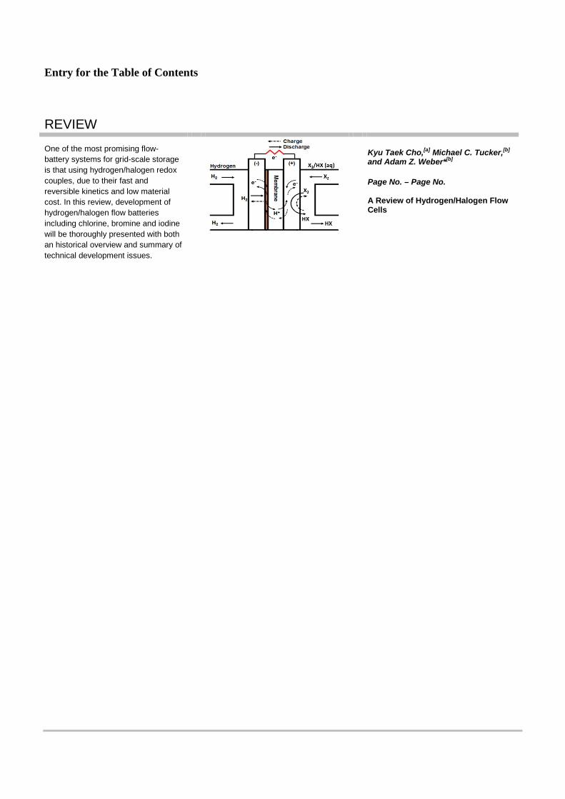
Entry for the Table of Contents
REVIEW One of the most promising flow-battery systems for grid-scale storage is that using hydrogen/halogen redox couples, due to their fast and reversible kinetics and low material cost. In this review, development of hydrogen/halogen flow batteries including chlorine, bromine and iodine will be thoroughly presented with both an historical overview and summary of technical development issues.
Kyu Taek Cho,[a] Michael C. Tucker,[b] and Adam Z. Weber*[b]
Page No. – Page No. A Review of Hydrogen/Halogen Flow Cells