vhdl lecture slides.pdf
TRANSCRIPT
7/27/2019 VHDL LECTURE SLIDES.pdf
http://slidepdf.com/reader/full/vhdl-lecture-slidespdf 1/90
OutlineOutline
sVHDL Background/History
sVHDL Design Example
sVHDL Model Components –Entity Declarations
–Architecture Descriptions
sBasic Syntax and Lexicographical
Conventions
7/27/2019 VHDL LECTURE SLIDES.pdf
http://slidepdf.com/reader/full/vhdl-lecture-slidespdf 2/90
Reasons for Using VHDLReasons for Using VHDL
sVHDL Is an International IEEE Standard
Specification Language (IEEE 1076-1993) for Describing Digital Hardware Used by Industry
Worldwide – VHDL is an acronym for VHSIC (Very High
S peed Integrated Circuit) Hardware Description
Language
7/27/2019 VHDL LECTURE SLIDES.pdf
http://slidepdf.com/reader/full/vhdl-lecture-slidespdf 3/90
Reasons for Using VHDLReasons for Using VHDL
sVHDL enables hardware modeling from the
gate to system level
s
VHDL provides a mechanism for digitaldesign and reusable design documentation
sVHDL Provides a Common Communications
Medium
7/27/2019 VHDL LECTURE SLIDES.pdf
http://slidepdf.com/reader/full/vhdl-lecture-slidespdf 4/90
A Brief History of VHDLA Brief History of VHDL
sVery High Speed Integrated Circuit
(VHSIC) Program –Launched in 1980
–Object was to achieve significant gains inVLSI technology by shortening the time from
concept to implementation (18 months to 6
months)
–Need for common descriptive language
7/27/2019 VHDL LECTURE SLIDES.pdf
http://slidepdf.com/reader/full/vhdl-lecture-slidespdf 5/90
A Brief History of VHDLA Brief History of VHDL
sWoods Hole Workshop
– Held in June 1981 in Massachusetts
– Discussion of VHSIC goals
– Comprised of members of industry,
government, and academia
7/27/2019 VHDL LECTURE SLIDES.pdf
http://slidepdf.com/reader/full/vhdl-lecture-slidespdf 6/90
A Brief History of VHDLA Brief History of VHDL
sJuly 1983: contract awarded to develop
VHDL –Intermetrics
–IBM
–Texas Instruments
sAugust 1985: VHDL Version 7.2 released
7/27/2019 VHDL LECTURE SLIDES.pdf
http://slidepdf.com/reader/full/vhdl-lecture-slidespdf 7/90
A Brief History of VHDLA Brief History of VHDL
sDecember 1987: VHDL became IEEE
Standard 1076-1987 and in 1988 an ANSIstandard
s September 1993: VHDL was restandardized toclarify and enhance the language
sVHDL has been accepted as a DraftInternational Standard by the IEC
7/27/2019 VHDL LECTURE SLIDES.pdf
http://slidepdf.com/reader/full/vhdl-lecture-slidespdf 8/90
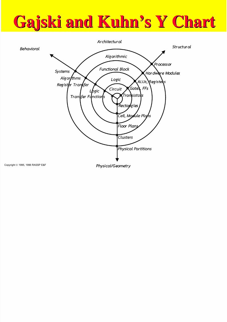
GajskiGajski and Kuhn’s Y Chartand Kuhn’s Y ChartArch i tec tura l Arch i tec tura l Arch i tec tura l Arch i tec tura l
Phy sical/ Geom etr y Phy sical/ Geom etr y Phy sical/ Geom etr y Phy sical/ Geom etr y
St ruc tu ra l S t ruc tu ra l S t ruc tu ra l S t ruc tu ra l Behavioral Behavioral Behavioral Behavioral
Pr ocessor Pr ocessor Pr ocessor Pr ocessor
Har dwar e Modules Har dwar e Modules Har dwar e Modules Har dwar e Modules
ALUs ALUs ALUs ALUs, Regist er s , Register s , Register s , Register s
Gates,Gates,Gates,Gat es, FFs FFs FFs FFs
Trans is tors Trans is tors Trans is tors Trans is tors
Systems Systems Systems Systems
A lgo r i t hms A lgo r i t hms A lgo r i t hms A lgo r i t hms
Register Tr an sfer Register Tr an sfer Register Tr an sfer Register Tr an sfer
Logic Logic Logic Logic
Tr ansfer Fun ct ions Tr ansfer Fun ct ions Tr ansfer Fun ct ions Tr ansfer Fun ct ions
A lgo r i t hm ic A lgo r i t hm ic A lgo r i t hm ic A lgo r i t hm ic
Funct iona l Block Funct iona l Block Funct iona l Block Funct iona l Block
Logic Logic Logic Logic
Circui t Circui t Circui t Circui t
Rectangles Rectangles Rectangles Rectangles
Cell, Modul e Plan s Cell, Modul e Plan s Cell, Modul e Plan s Cell, Modul e Plan s
Floor Plans Floor Plans Floor Plans Floor Plans
Clusters Clusters Clusters Clusters
Phy sical Par t i t ions Phy sical Par t i t ions Phy sical Par t i t ions Phy sical Par t i t ions
Copyright 1995, 1996 RASSP E&F
7/27/2019 VHDL LECTURE SLIDES.pdf
http://slidepdf.com/reader/full/vhdl-lecture-slidespdf 9/90
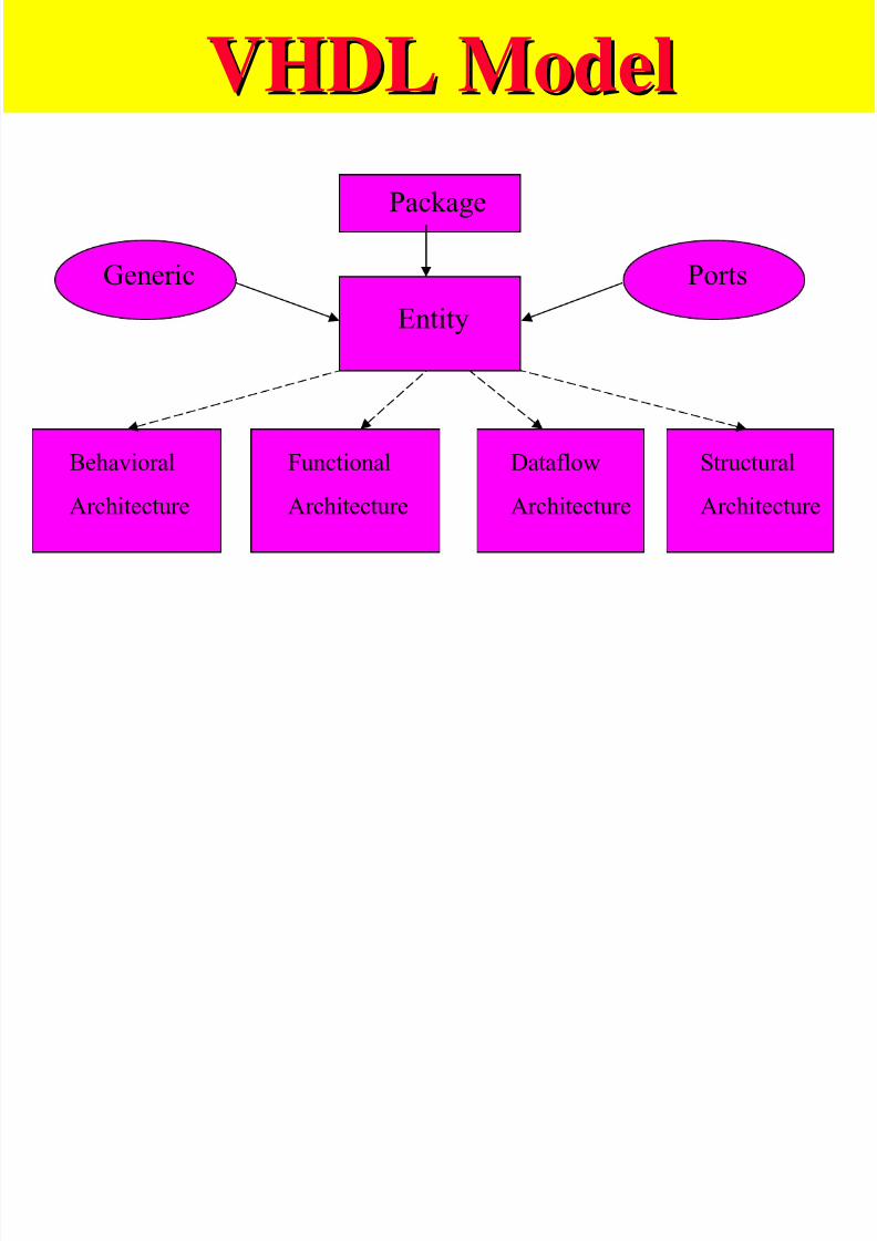
VHDL ModelVHDL Model
Behavioral
Architecture
Dataflow
Architecture
Structural
Architecture
Package
Entity
Generic Ports
Functional
Architecture
7/27/2019 VHDL LECTURE SLIDES.pdf
http://slidepdf.com/reader/full/vhdl-lecture-slidespdf 10/90
VHDLVHDL CombinationalCombinational
TemplateTemplate
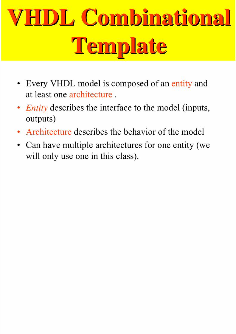
• Every VHDL model is composed of an entity and
at least one architecture .
• Entity describes the interface to the model (inputs,
outputs)
• Architecture describes the behavior of the model
• Can have multiple architectures for one entity (we
will only use one in this class).
A VHDL T l t fA VHDL T l t f
7/27/2019 VHDL LECTURE SLIDES.pdf
http://slidepdf.com/reader/full/vhdl-lecture-slidespdf 11/90
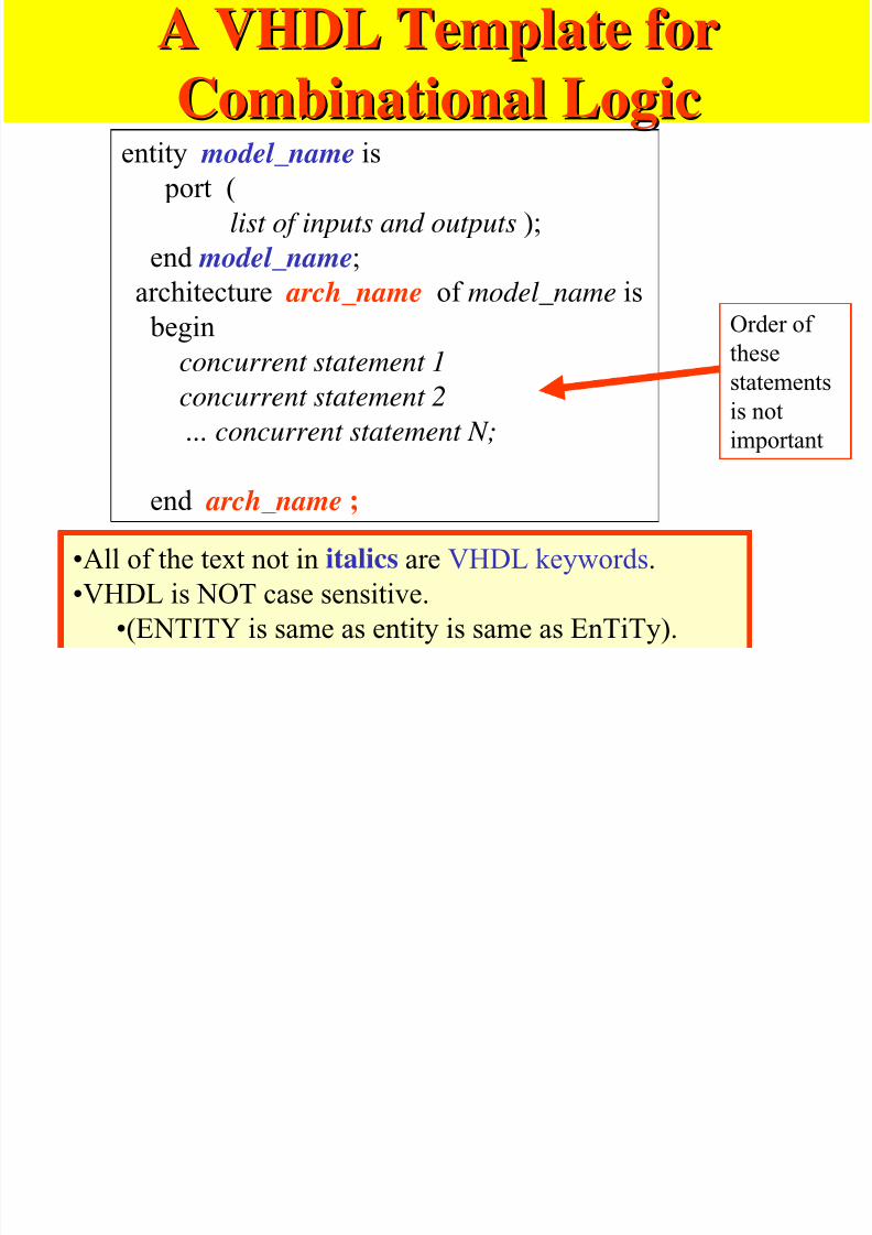
A VHDL Template forA VHDL Template for
CombinationalCombinational LogicLogicentity model_name is
port (
list of inputs and outputs );end model_name;
architecture arch_name of model_name is
begin
concurrent statement 1
concurrent statement 2
... concurrent statement N;
end arch_name ;
•All of the text not in italics are VHDL keywords.•VHDL is NOT case sensitive.
•(ENTITY is same as entity is same as EnTiTy).
Order of
these
statements
is not
important
7/27/2019 VHDL LECTURE SLIDES.pdf
http://slidepdf.com/reader/full/vhdl-lecture-slidespdf 12/90
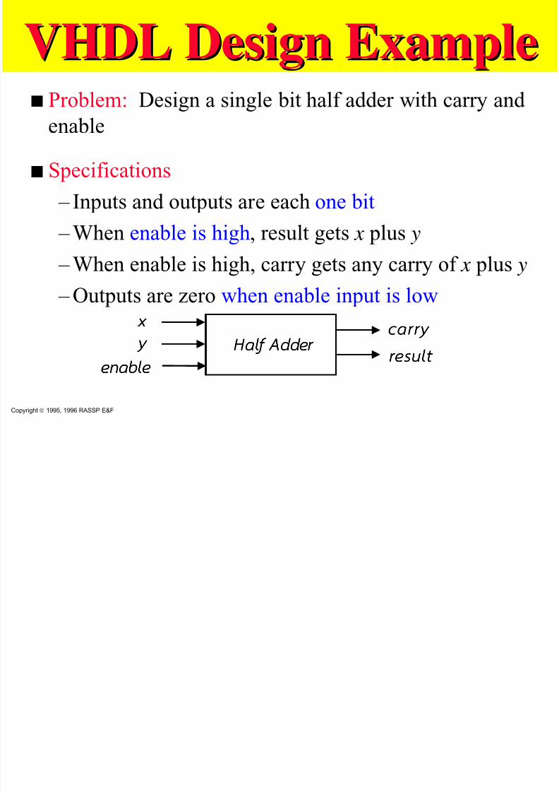
VHDL Design ExampleVHDL Design Examples Problem: Design a single bit half adder with carry and
enable
s Specifications
– Inputs and outputs are each one bit
– When enable is high, result gets x plus y
– When enable is high, carry gets any carry of x plus y
– Outputs are zero when enable input is lowx xx x
y yy y
enable enable enable enable
ca r r y ca r r y ca r r y ca r r y
resul t resul t resul t resul t Hal f Adder Hal f Adder Hal f Adder Hal f Adder
Copyright 1995, 1996 RASSP E&F

7/27/2019 VHDL LECTURE SLIDES.pdf
http://slidepdf.com/reader/full/vhdl-lecture-slidespdf 13/90
VHDL Design ExampleVHDL Design ExampleEntity DeclarationEntity Declaration
sAs a first step, the entity declaration
describes the interface of the component
– input and output ports are declared
x xx x
y yy y
enable enable enable enable
ca r r y ca r r y ca r r y ca r r y
resul t resul t resul t resul t
Hal f Hal f Hal f Hal f
Adder Adder Adder Adder
ENTITY half_adder IS
PORT( x, y, enable: IN BIT;
carry, result: OUT BIT);
END half_adder;
Copyright 1995, 1996 RASSP E&F
We will, at least at first, useWe will, at least at first, use
capitals and colors to denotecapitals and colors to denoteVHDL language componentsVHDL language components
7/27/2019 VHDL LECTURE SLIDES.pdf
http://slidepdf.com/reader/full/vhdl-lecture-slidespdf 14/90
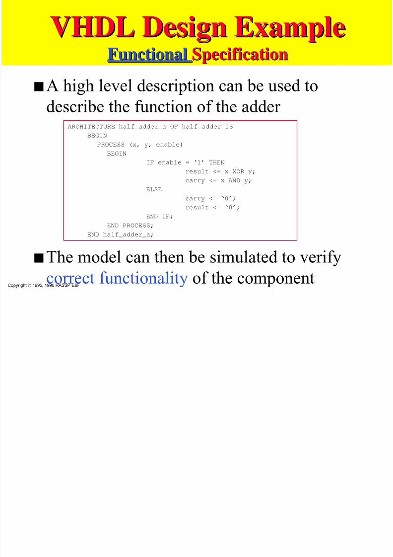
VHDL Design ExampleVHDL Design ExampleFunctionalFunctional SpecificationSpecification
sA high level description can be used to
describe the function of the adder
sThe model can then be simulated to verifycorrect functionality of the component
ARCHITECTURE half_adder_a OF half_adder IS
BEGIN
PROCESS (x, y, enable)
BEGINIF enable = ‘1’ THEN
result <= x XOR y;
carry <= x AND y;
ELSE
carry <= ‘0’;
result <= ‘0’;END IF;
END PROCESS;
END half_adder_a;
Copyright 1995, 1996 RASSP E&F
VHDL Design ExampleVHDL Desi n Exam le
7/27/2019 VHDL LECTURE SLIDES.pdf
http://slidepdf.com/reader/full/vhdl-lecture-slidespdf 15/90
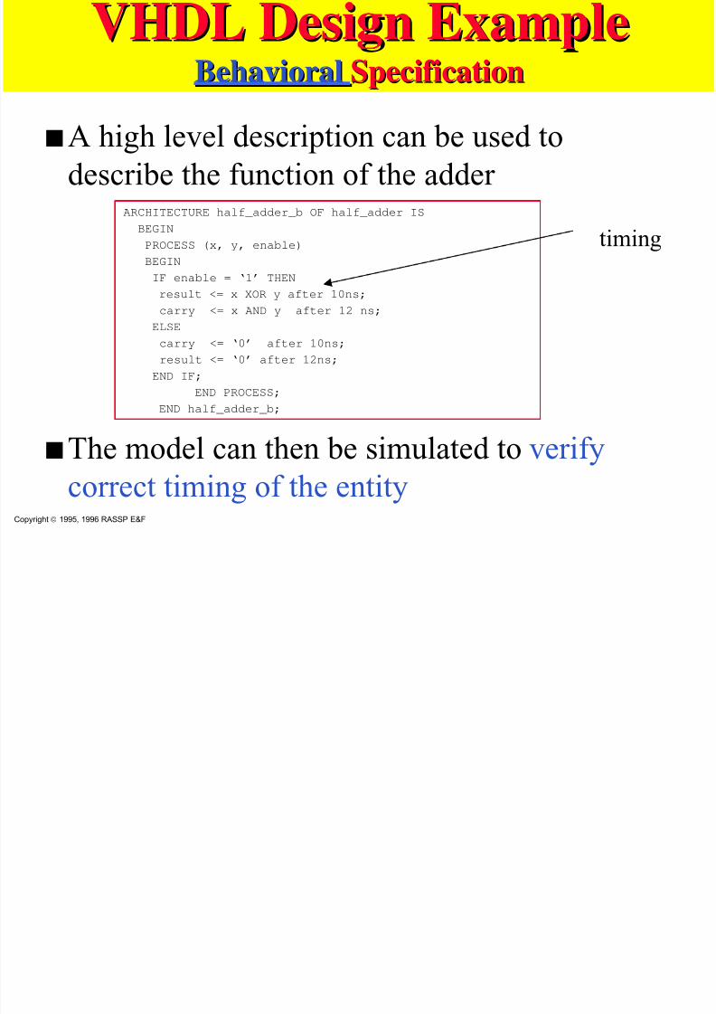
VHDL Design ExampleVHDL Desi n Exam leBehavioralBehavioral SpecificationSpecification
sA high level description can be used to
describe the function of the adder
sThe model can then be simulated to verify
correct timing of the entity
ARCHITECTURE half_adder_b OF half_adder IS
BEGIN
PROCESS (x, y, enable)
BEGIN
IF enable = ‘1’ THEN
result <= x XOR y after 10ns;
carry <= x AND y after 12 ns;
ELSE
carry <= ‘0’ after 10ns;
result <= ‘0’ after 12ns;
END IF;END PROCESS;
END half_adder_b;
Copyright 1995, 1996 RASSP E&F
timing
VHDL D i E lVHDL D i E l
7/27/2019 VHDL LECTURE SLIDES.pdf
http://slidepdf.com/reader/full/vhdl-lecture-slidespdf 16/90
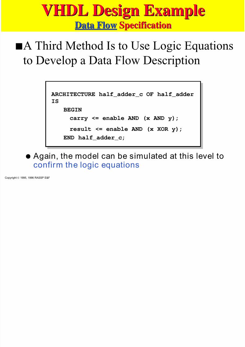
VHDL Design ExampleVHDL Design ExampleData FlowData Flow SpecificationSpecification
sA Third Method Is to Use Logic Equations
to Develop a Data Flow Description
q Again, the model can be simulated at this level toconfirm the logic equations
ARCHITECTURE half_adder_c OF half_adderIS
BEGIN
carry <= enable AND (x AND y);
result <= enable AND (x XOR y);END half_adder_c;
Copyright 1995, 1996 RASSP E&F
VHDL D i E lVHDL D i E l
7/27/2019 VHDL LECTURE SLIDES.pdf
http://slidepdf.com/reader/full/vhdl-lecture-slidespdf 17/90
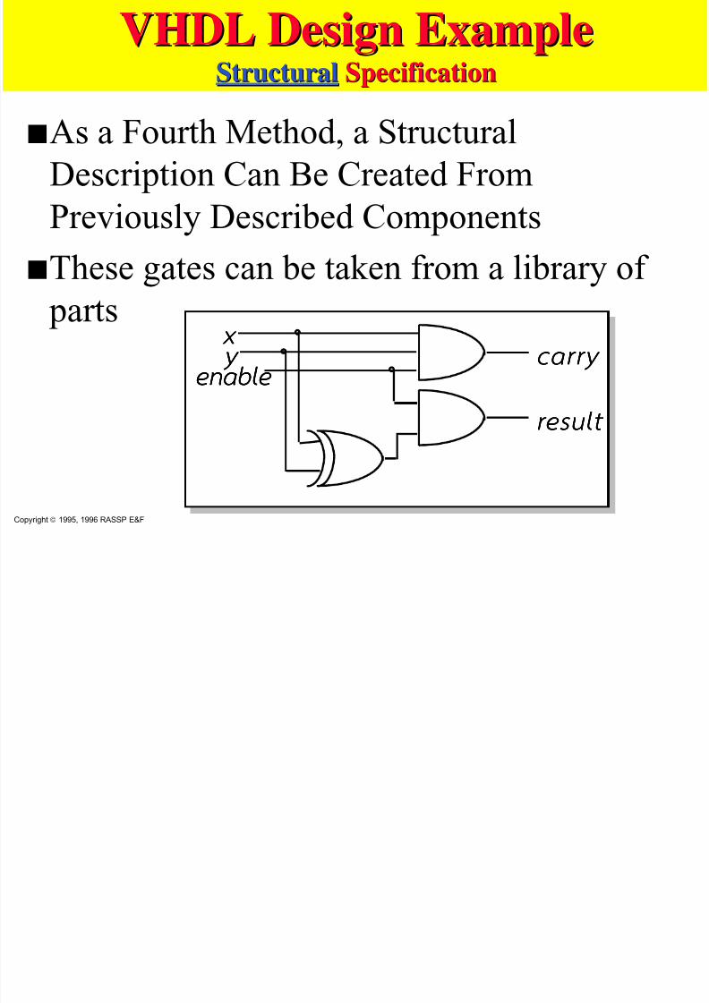
VHDL Design ExampleVHDL Design ExampleStructuralStructural SpecificationSpecification
sAs a Fourth Method, a Structural
Description Can Be Created FromPreviously Described Components
s
These gates can be taken from a library of partsx xx x y yy y
enable enable enable enable ca r r y ca r r y ca r r y ca r r y
resul t resul t resul t resul t
Copyright 1995, 1996 RASSP E&F
VHDL D i E lVHDL D i E l
7/27/2019 VHDL LECTURE SLIDES.pdf
http://slidepdf.com/reader/full/vhdl-lecture-slidespdf 18/90
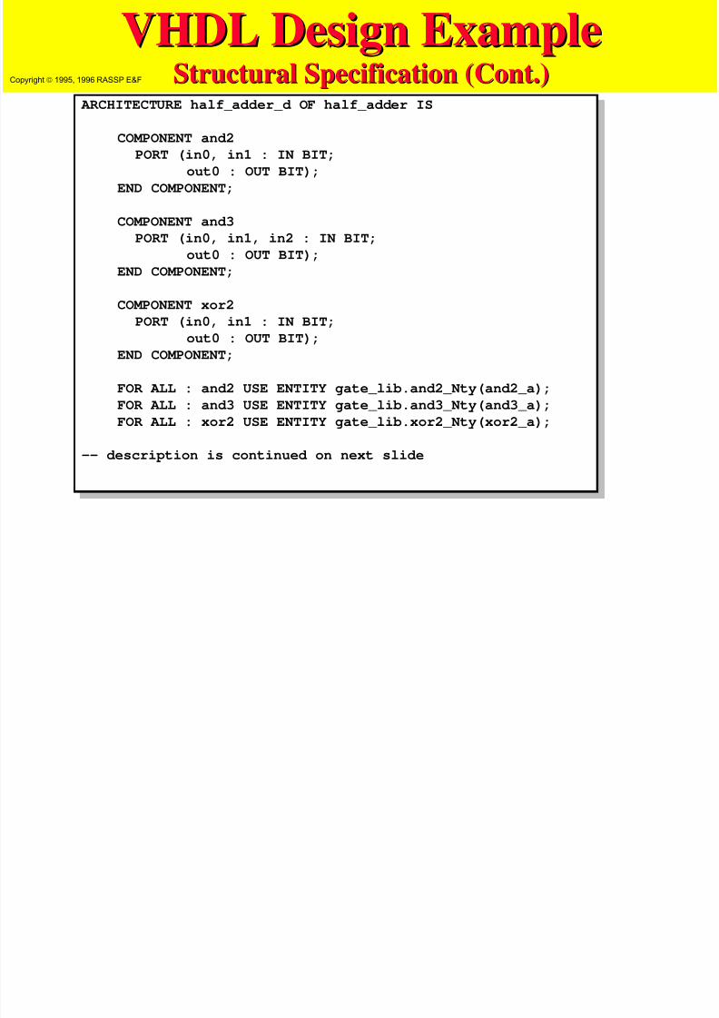
VHDL Design ExampleVHDL Design ExampleStructural Specification (Structural Specification (ContCont.).)
ARCHITECTURE half_adder_d OF half_adder IS
COMPONENT and2
PORT (in0, in1 : IN BIT;
out0 : OUT BIT);
END COMPONENT;
COMPONENT and3
PORT (in0, in1, in2 : IN BIT;
out0 : OUT BIT);
END COMPONENT;
COMPONENT xor2
PORT (in0, in1 : IN BIT;
out0 : OUT BIT);
END COMPONENT;
FOR ALL : and2 USE ENTITY gate_lib.and2_Nty(and2_a);
FOR ALL : and3 USE ENTITY gate_lib.and3_Nty(and3_a);
FOR ALL : xor2 USE ENTITY gate_lib.xor2_Nty(xor2_a);
-- description is continued on next slide
Copyright 1995, 1996 RASSP E&F

7/27/2019 VHDL LECTURE SLIDES.pdf
http://slidepdf.com/reader/full/vhdl-lecture-slidespdf 19/90
VHDL Design ExampleVHDL Design ExampleStructural Specification (Structural Specification (ContCont.).)
-- continuing half_adder_d description
SIGNAL xor_res : BIT; -- internal signal
-- Note that other signals are already declared in entity
BEGIN
A0 : and2 PORT MAP (enable, xor_res, result);
A1 : and3 PORT MAP (x, y, enable, carry);X0 : xor2 PORT MAP (x, y, xor_res);
END half_adder_d;
Copyright 1995, 1996 RASSP E&F
7/27/2019 VHDL LECTURE SLIDES.pdf
http://slidepdf.com/reader/full/vhdl-lecture-slidespdf 20/90
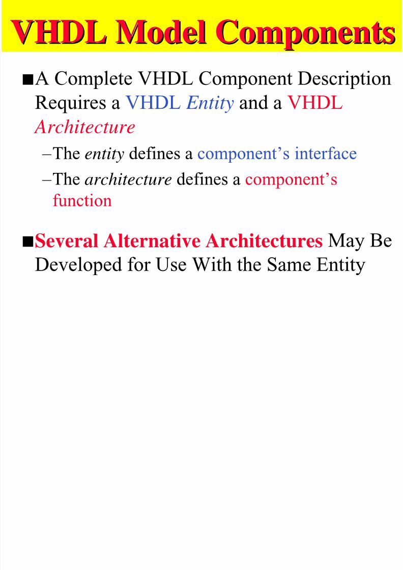
VHDL Model ComponentsVHDL Model Components
sA Complete VHDL Component Description
Requires a VHDL Entity and a VHDL Architecture
–The entity defines a component’s interface –The architecture defines a component’s
function
sSeveral Alternative Architectures May Be
Developed for Use With the Same Entity
7/27/2019 VHDL LECTURE SLIDES.pdf
http://slidepdf.com/reader/full/vhdl-lecture-slidespdf 21/90
VHDL Model ComponentsVHDL Model Components
sThree Areas of Description for a VHDL
Component: – Structural descriptions
– Functional descriptions
– Timing and delay descriptions (Behavioral)
M j it G t E lMajority Gate Example
7/27/2019 VHDL LECTURE SLIDES.pdf
http://slidepdf.com/reader/full/vhdl-lecture-slidespdf 22/90
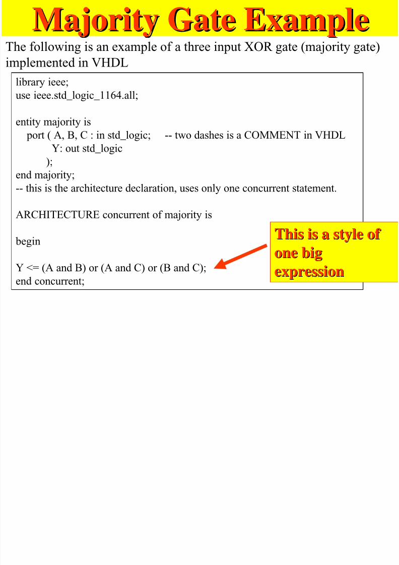
Majority Gate ExampleMajority Gate ExampleThe following is an example of a three input XOR gate (majority gate)
implemented in VHDL
library ieee;
use ieee.std_logic_1164.all;
entity majority is
port ( A, B, C : in std_logic; -- two dashes is a COMMENT in VHDL
Y: out std_logic
);end majority;
-- this is the architecture declaration, uses only one concurrent statement.
ARCHITECTURE concurrent of majority is
begin
Y <= (A and B) or (A and C) or (B and C);
end concurrent;
This is a style of This is a style of
one bigone big
expressionexpression
M j it G t ith T Si lMajorit Gate ith Temporar Signals

7/27/2019 VHDL LECTURE SLIDES.pdf
http://slidepdf.com/reader/full/vhdl-lecture-slidespdf 23/90
Majority Gate with Temporary SignalsMajority Gate with Temporary Signals
The following version of the majority gate uses sometemporary signals (entity has been left out, is same).
-- the architecture now uses 4 concurrent statements
ARCHITECTURE newconc of majority is
signal t1, t2, t3 : std_logic ;
begin
t1 <= A and B;
t2 <= A and C;
t3 <= B and C;
Y <= t1 or t2 or t3;
end newconc;
Note that temporary signals are declared between architecture
statement and begin statement.
Explain why this style is
often more convenient to
use
Majority gate:Majority gate:Variant 2Variant 2
Concurrent statement, no process
Majority Gate with when elseMajority Gate with when-else
7/27/2019 VHDL LECTURE SLIDES.pdf
http://slidepdf.com/reader/full/vhdl-lecture-slidespdf 24/90
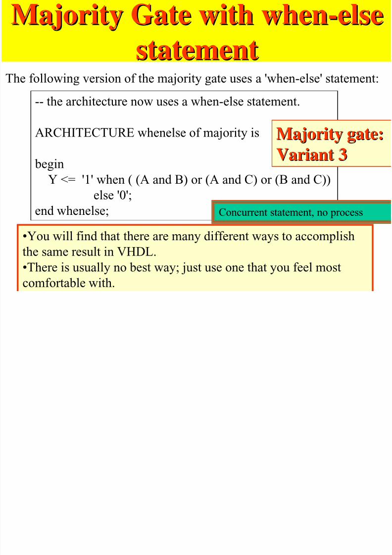
Majority Gate with when-elseMajority Gate with when-else
statementstatementThe following version of the majority gate uses a 'when-else' statement:
-- the architecture now uses a when-else statement.
ARCHITECTURE whenelse of majority is
begin
Y <= '1' when ( (A and B) or (A and C) or (B and C))
else '0';
end whenelse;
•You will find that there are many different ways to accomplish
the same result in VHDL.
•There is usually no best way; just use one that you feel most
comfortable with.
Majority gate:Majority gate:
Variant 3Variant 3
Concurrent statement, no process
C t V S ti lConcurrent Versus Sequential
7/27/2019 VHDL LECTURE SLIDES.pdf
http://slidepdf.com/reader/full/vhdl-lecture-slidespdf 25/90
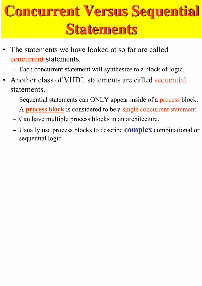
Concurrent Versus SequentialConcurrent Versus Sequential
StatementsStatements• The statements we have looked at so far are called
concurrent statements.
– Each concurrent statement will synthesize to a block of logic.
• Another class of VHDL statements are called sequentialstatements.
– Sequential statements can ONLY appear inside of a process block.
– A process block is considered to be a single concurrent statement.
– Can have multiple process blocks in an architecture.
– Usually use process blocks to describe complex combinational or sequential logic.
ProcessProcess
7/27/2019 VHDL LECTURE SLIDES.pdf
http://slidepdf.com/reader/full/vhdl-lecture-slidespdf 26/90
ProcessProcesssFundamental Unit for Component
Behavior Description Is the Process – Processes may be explicitly or implicitly
defined
–They are packaged in architectures
7/27/2019 VHDL LECTURE SLIDES.pdf
http://slidepdf.com/reader/full/vhdl-lecture-slidespdf 27/90
VHDL Model ComponentsVHDL Model Components
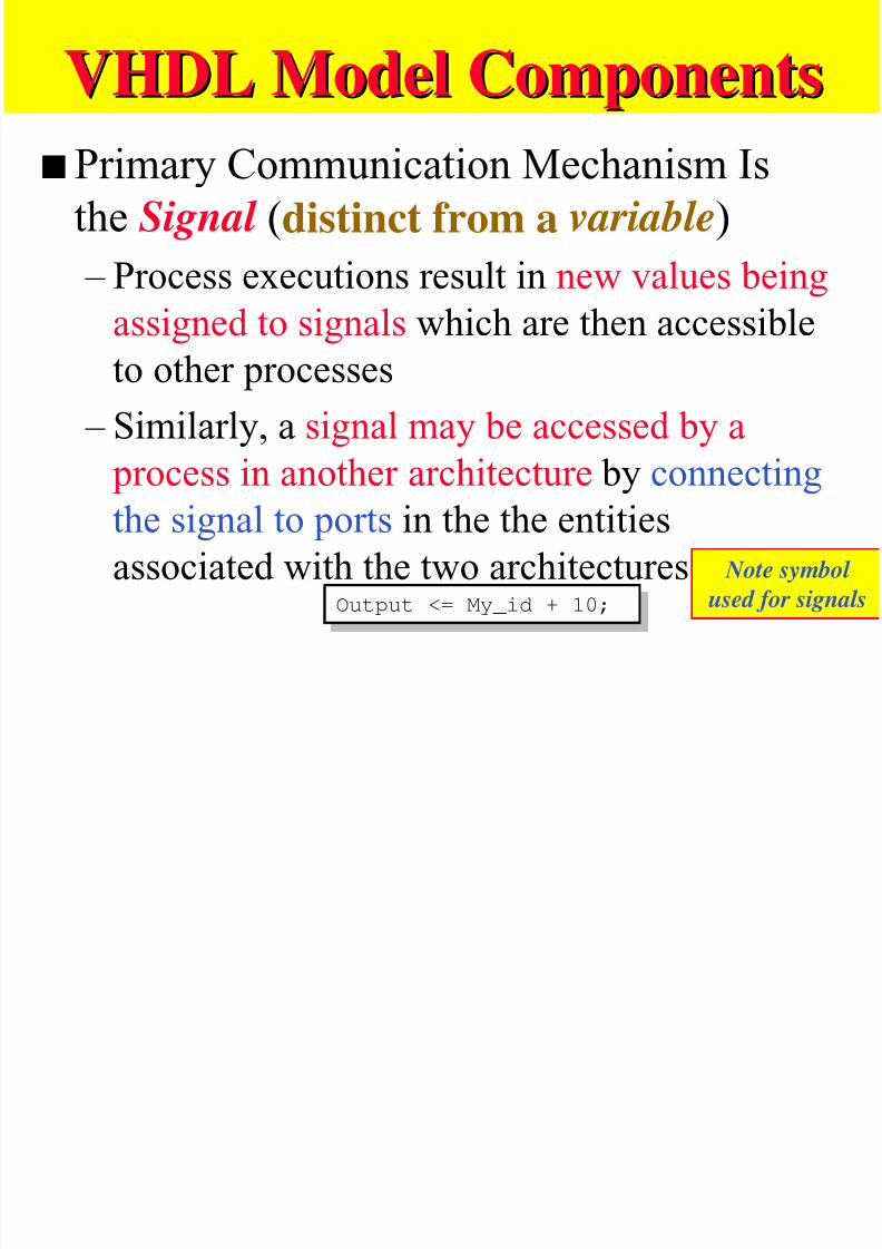
s Primary Communication Mechanism Is
the Signal (distinct from a variable) – Process executions result in new values being
assigned to signals which are then accessible
to other processes
– Similarly, a signal may be accessed by a
process in another architecture by connectingthe signal to ports in the the entities
associated with the two architecturesOutput <= My_id + 10;Output <= My_id + 10;
Note symbol
used for signals
VHDL EntityVHDL Entity

7/27/2019 VHDL LECTURE SLIDES.pdf
http://slidepdf.com/reader/full/vhdl-lecture-slidespdf 28/90
VHDL EntityVHDL EntitysThe Primary Purpose of an Entity Is to Declare
the Input and Output Signals WhichCommunicate With It.
– Interface signals are listed in the PORT clausewhich has 3 parts:
»Name
»Mode
»Data type
VHDL E tit E lVHDL E tit E l

7/27/2019 VHDL LECTURE SLIDES.pdf
http://slidepdf.com/reader/full/vhdl-lecture-slidespdf 29/90
VHDL Entity ExampleVHDL Entity Example
ENTITY OR3 IS
PORT ( A, B, C : IN BIT;
D : OUT BIT );
END OR3;
Entit DeclarationsEntit Declarations
7/27/2019 VHDL LECTURE SLIDES.pdf
http://slidepdf.com/reader/full/vhdl-lecture-slidespdf 30/90
Entity DeclarationsEntit DeclarationssThe Primary Purpose of the Entity Is to
Declare the Signals in theComponent’s Interface
–The interface signals are listed in thePORT clause
»In this respect, the entity is akin to theschematic symbol for the component
Copyright 1995, 1996 RASSP E&F
7/27/2019 VHDL LECTURE SLIDES.pdf
http://slidepdf.com/reader/full/vhdl-lecture-slidespdf 31/90
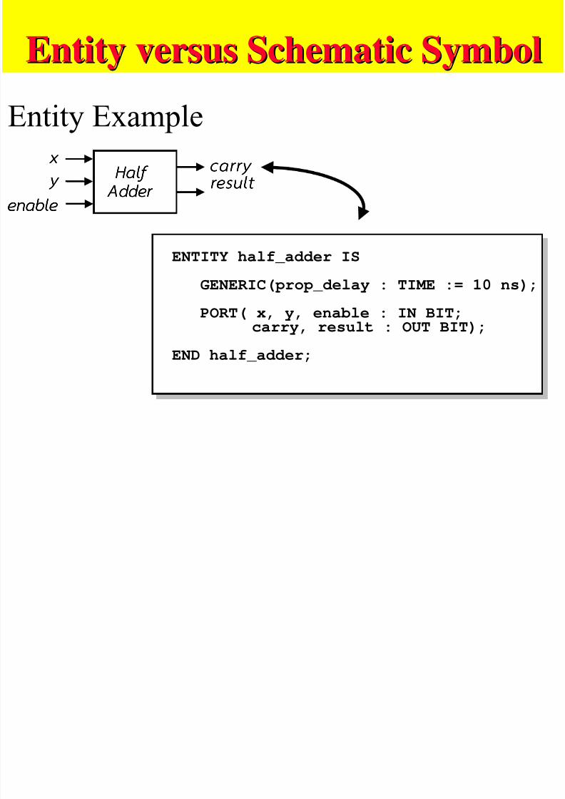
Entity versus Schematic SymbolEntity versus Schematic Symbol
Entity Example
x xx x
y yy y
enable enable enable enable
ca r r y ca r r y ca r r y ca r r y
resul t resul t resul t resul t Hal f Hal f Hal f Hal f
Adder Adder Adder Adder
ENTITY half_adder IS
GENERIC(prop_delay : TIME := 10 ns);
PORT( x, y, enable : IN BIT;carry, result : OUT BIT);
END half_adder;
Entity DeclarationsEntit Declarations
7/27/2019 VHDL LECTURE SLIDES.pdf
http://slidepdf.com/reader/full/vhdl-lecture-slidespdf 32/90
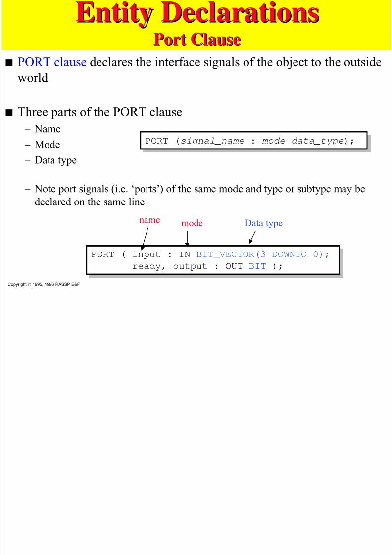
Entity DeclarationsEntit DeclarationsPort ClausePort Clause
s PORT clause declares the interface signals of the object to the outside
world
s Three parts of the PORT clause
– Name
– Mode
– Data type
– Note port signals (i.e. ‘ports’) of the same mode and type or subtype may be
declared on the same line
PORT (signal_name : mode data_type);PORT (signal_name : mode data_type);
PORT ( input : IN BIT_VECTOR(3 DOWNTO 0); ready, output : OUT BIT );
PORT ( input : IN BIT_VECTOR(3 DOWNTO 0);
ready, output : OUT BIT );
Copyright 1995, 1996 RASSP E&F
name mode Data type
Entity DeclarationsEntity Declarations
7/27/2019 VHDL LECTURE SLIDES.pdf
http://slidepdf.com/reader/full/vhdl-lecture-slidespdf 33/90
Entity DeclarationsEntity DeclarationsPort Clause (Port Clause (ContCont.).)
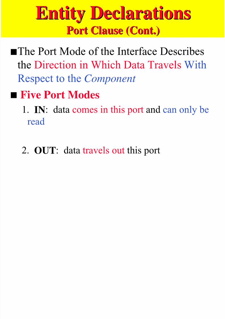
sThe Port Mode of the Interface Describes
the Direction in Which Data Travels With
Respect to the Component
s Five Port Modes
1. IN: data comes in this port and can only be
read
2. OUT: data travels out this port
Entity DeclarationsEntity Declarations

7/27/2019 VHDL LECTURE SLIDES.pdf
http://slidepdf.com/reader/full/vhdl-lecture-slidespdf 34/90
Entity DeclarationsEntity DeclarationsPort Clause (Port Clause (ContCont.).)
3. BUFFER: bidirectional data, but only one
signal driver may be enabled at any one time
4. INOUT: bidirectional data with any number
of active drivers allowed but requires a Bus
Resolution Function
5. LINKAGE: direction of data is unknown
E tit D l tiEntity Declarations
7/27/2019 VHDL LECTURE SLIDES.pdf
http://slidepdf.com/reader/full/vhdl-lecture-slidespdf 35/90
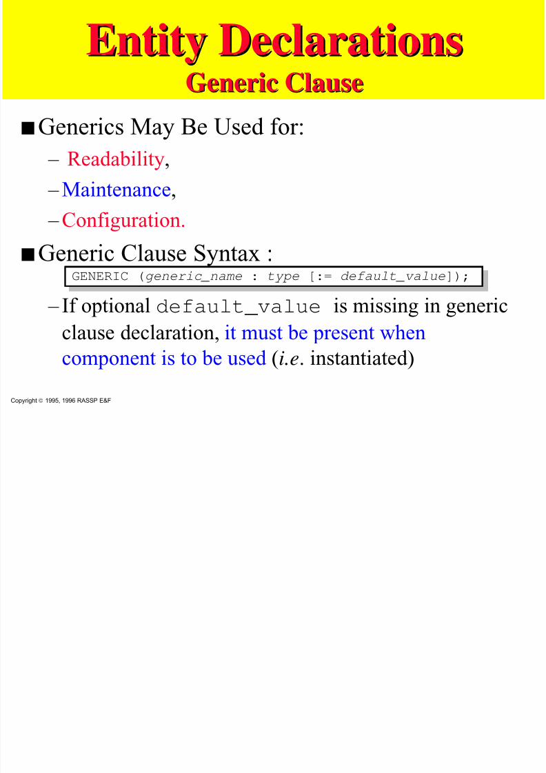
Entity DeclarationsEntity DeclarationsGeneric ClauseGeneric Clause
sGenerics May Be Used for:
– Readability,
– Maintenance,
– Configuration.
sGeneric Clause Syntax :
– If optional default_value is missing in generic
clause declaration, it must be present when
component is to be used (i.e. instantiated)
GENERIC (generic_name : type [:= default_value]);GENERIC (generic_name : type [:= default_value]);
Copyright 1995, 1996 RASSP E&F
B h i l D i tiBehavioral Descriptions
7/27/2019 VHDL LECTURE SLIDES.pdf
http://slidepdf.com/reader/full/vhdl-lecture-slidespdf 36/90
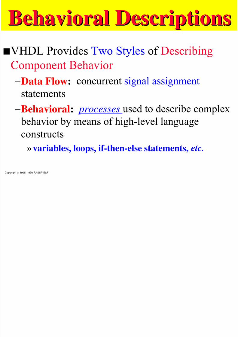
Behavioral DescriptionsBehavioral Descriptions
sVHDL Provides Two Styles of Describing
Component Behavior – Data Flow: concurrent signal assignment
statements – Behavioral: processes used to describe complex
behavior by means of high-level languageconstructs
» variables, loops, if-then-else statements, etc.
Copyright 1995, 1996 RASSP E&F
Majority Gate usingMajority Gate using process process block andblock and if if statementstatement
7/27/2019 VHDL LECTURE SLIDES.pdf
http://slidepdf.com/reader/full/vhdl-lecture-slidespdf 37/90
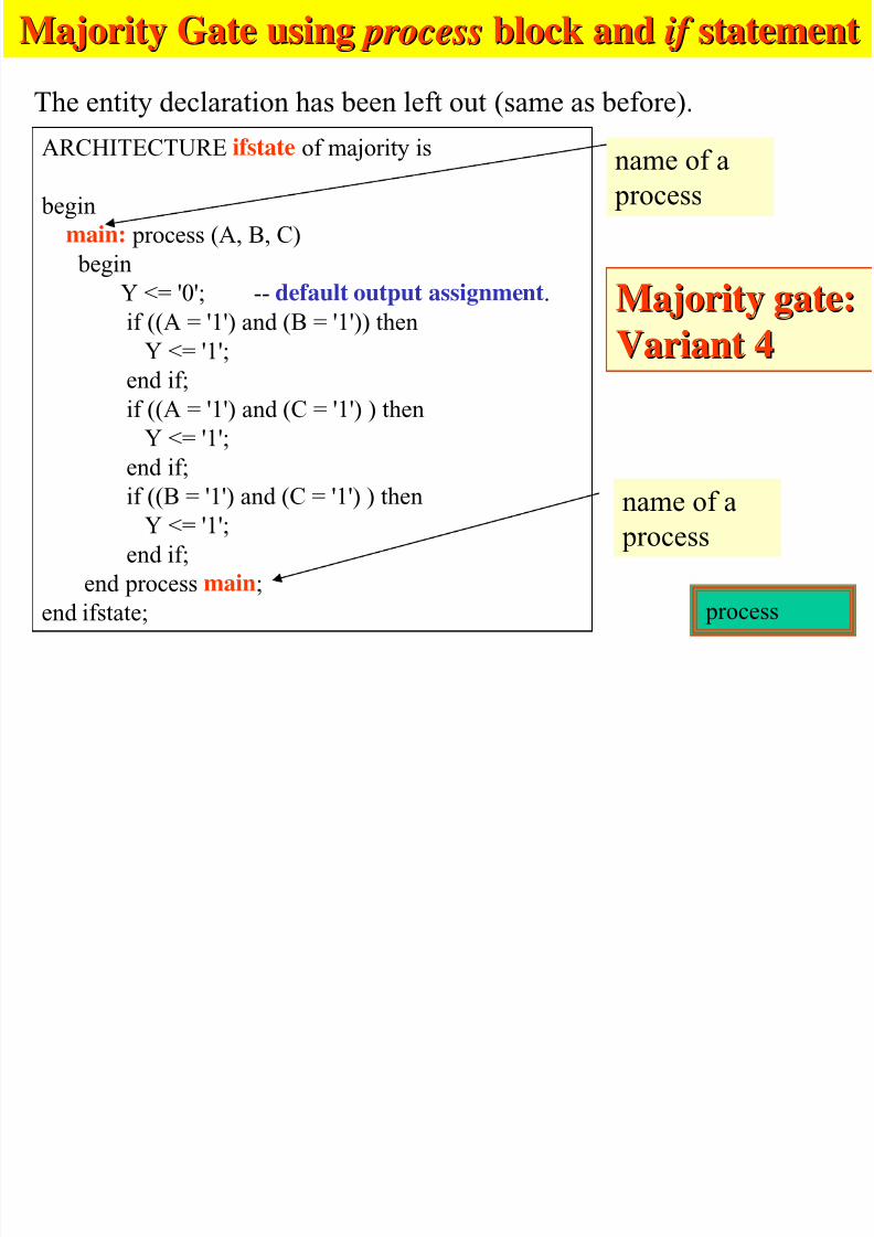
The entity declaration has been left out (same as before).
ARCHITECTURE ifstate of majority is
begin
main: process (A, B, C)begin
Y <= '0'; -- default output assignment.
if ((A = '1') and (B = '1')) then
Y <= '1';end if;
if ((A = '1') and (C = '1') ) then
Y <= '1';
end if;if ((B = '1') and (C = '1') ) then
Y <= '1';
end if;
end process main;end ifstate;
name of a
process
name of a
process
Majority gate:Majority gate:
Variant 4Variant 4
process
Comments on process blockComments on process block
7/27/2019 VHDL LECTURE SLIDES.pdf
http://slidepdf.com/reader/full/vhdl-lecture-slidespdf 38/90
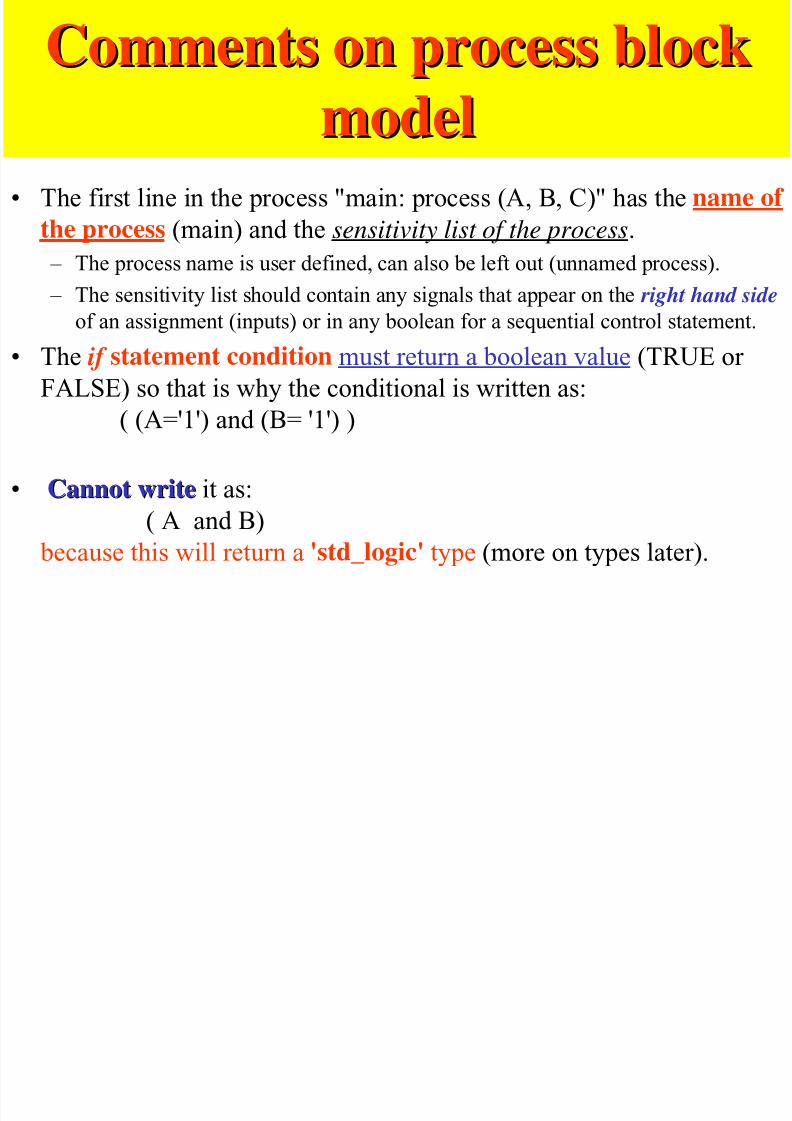
Comments on process blockComments on process block
modelmodel• The first line in the process "main: process (A, B, C)" has the name of
the process (main) and the sensitivity list of the process.
– The process name is user defined, can also be left out (unnamed process).
– The sensitivity list should contain any signals that appear on the right hand side
of an assignment (inputs) or in any boolean for a sequential control statement.
• The if statement condition must return a boolean value (TRUE or
FALSE) so that is why the conditional is written as:
( (A='1') and (B= '1') )
• Cannot writeCannot write it as:
( A and B) because this will return a 'std_logic' type (more on types later).
Use ofUse of if-elseif-else
7/27/2019 VHDL LECTURE SLIDES.pdf
http://slidepdf.com/reader/full/vhdl-lecture-slidespdf 39/90
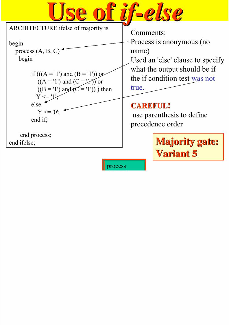
Use of Use of if-elseif-elseARCHITECTURE ifelse of majority is
begin
process (A, B, C)
begin
if (((A = '1') and (B = '1')) or
((A = '1') and (C = '1')) or
((B = '1') and (C = '1')) ) then
Y <= '1';
else
Y <= '0';
end if;
end process;
end ifelse;
Comments:Process is anonymous (no
name)
Used an 'else' clause to specifywhat the output should be if
the if condition test was not
true.
CAREFUL!CAREFUL!
use parenthesis to define
precedence order
Majority gate:Majority gate:
Variant 5Variant 5 process

7/27/2019 VHDL LECTURE SLIDES.pdf
http://slidepdf.com/reader/full/vhdl-lecture-slidespdf 40/90
Generic ClauseGeneric Clauses Generic Clause Example :
– The generic My_ID, with a default value of 37, can be
referenced by any architecture of the entity with thisgeneric clause
– The default can be overridden at component instantiation
GENERIC (My_ID : INTEGER := 37);GENERIC (My_ID : INTEGER := 37);
GENERIC can be
time, current,voltage, signal…..
Architecture BodiesArchitecture Bodies

7/27/2019 VHDL LECTURE SLIDES.pdf
http://slidepdf.com/reader/full/vhdl-lecture-slidespdf 41/90
Architecture BodiesArchitecture Bodies
sDescribes the Operation of the
Component, Not Just Its Interface
sMore Than One Architecture Can (and
Usually Is) Associated With EachEntity
Architecture BodiesArchitecture Bodies
7/27/2019 VHDL LECTURE SLIDES.pdf
http://slidepdf.com/reader/full/vhdl-lecture-slidespdf 42/90
Architecture BodiesArchitecture Bodies
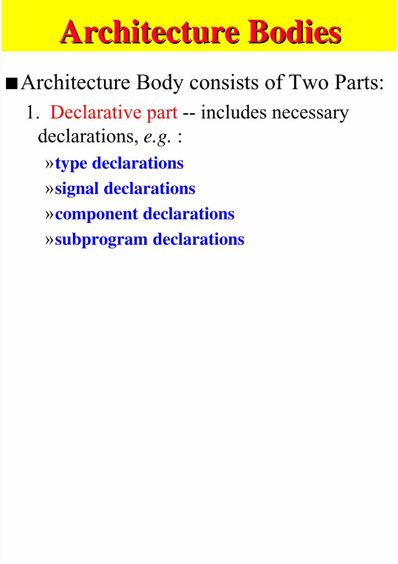
sArchitecture Body consists of Two Parts:
1. Declarative part -- includes necessarydeclarations, e.g. :
»type declarations»signal declarations
»component declarations»subprogram declarations
Architecture BodiesArchitecture Bodies
7/27/2019 VHDL LECTURE SLIDES.pdf
http://slidepdf.com/reader/full/vhdl-lecture-slidespdf 43/90
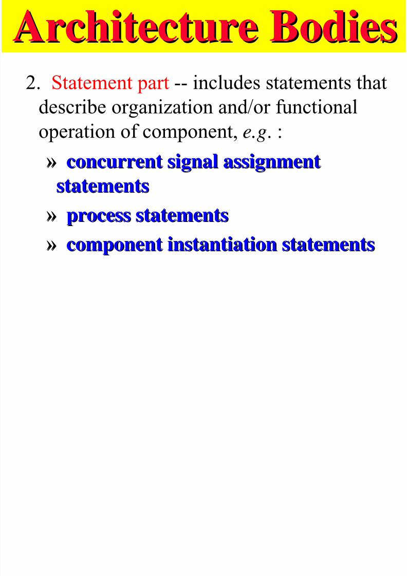
Architecture BodiesArchitecture Bodies2. Statement part -- includes statements that
describe organization and/or functionaloperation of component, e.g. :
»» concurrent signal assignmentconcurrent signal assignmentstatementsstatements
»» process statementsprocess statements»» component instantiation statementscomponent instantiation statements
Architecture Body ExampleArchitecture Body Example
7/27/2019 VHDL LECTURE SLIDES.pdf
http://slidepdf.com/reader/full/vhdl-lecture-slidespdf 44/90
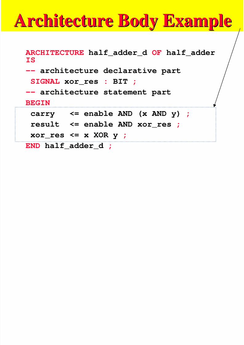
Architecture Body ExampleArchitecture Body Example
ARCHITECTURE half_adder_d OF half_adderIS
-- architecture declarative part
SIGNAL xor_res : BIT ;
-- architecture statement part
BEGIN
carry <= enable AND (x AND y) ;
result <= enable AND xor_res ;
xor_res <= x XOR y ;
END half_adder_d ;
Lexical Elements of VHDLLexical Elements of VHDL
7/27/2019 VHDL LECTURE SLIDES.pdf
http://slidepdf.com/reader/full/vhdl-lecture-slidespdf 45/90
Lexical Elements of VHDLLexical Elements of VHDL
sComments
– two dashes to end of line is a comment, e.g.,
--this is a comment
Copyright 1997, KJH
Lexical Elements of VHDLLexical Elements of VHDL
7/27/2019 VHDL LECTURE SLIDES.pdf
http://slidepdf.com/reader/full/vhdl-lecture-slidespdf 46/90
Lexical Elements of VHDLLexical Elements of VHDL
sBasic Identifiers
– Can Only Use» alphabetic letters ( A-Z, a-z ), or
» Decimal digits ( 0-9 ), or
» Underline character ( _ )
– Must Start With Alphabetic Letter ( MyVal )
Copyright 1997, KJH
Lexical Elements of VHDLLexical Elements of VHDL
7/27/2019 VHDL LECTURE SLIDES.pdf
http://slidepdf.com/reader/full/vhdl-lecture-slidespdf 47/90
Lexical Elements of VHDLLexical Elements of VHDL
s Basic Identifiers
– Not case sensitive( LastValue = = lAsTvALue)
– May NOT end with underline ( MyVal_ )
– May NOT contain sequential underlines (My__Val)
Copyright 1997, KJH
Not case sensitive, but recommended to use always the same way. It is also
recommended to use capitals for language
components
Lexical Elements of VHDLLexical Elements of VHDL
7/27/2019 VHDL LECTURE SLIDES.pdf
http://slidepdf.com/reader/full/vhdl-lecture-slidespdf 48/90
Lexical Elements of VHDLLexical Elements of VHDL
s Extended Identifiers
– Any character(s) enclosed by \ \
– Case IS significant in Extended Identifiers
– Extended identifiers are distinct from basic identifiers
– If “ \ ” is needed in extended identifier, use
“ \\ “
Copyright 1997, KJH
Lexical Elements of VHDLLexical Elements of VHDL
7/27/2019 VHDL LECTURE SLIDES.pdf
http://slidepdf.com/reader/full/vhdl-lecture-slidespdf 49/90
Lexical Elements of VHDLLexical Elements of VHDL
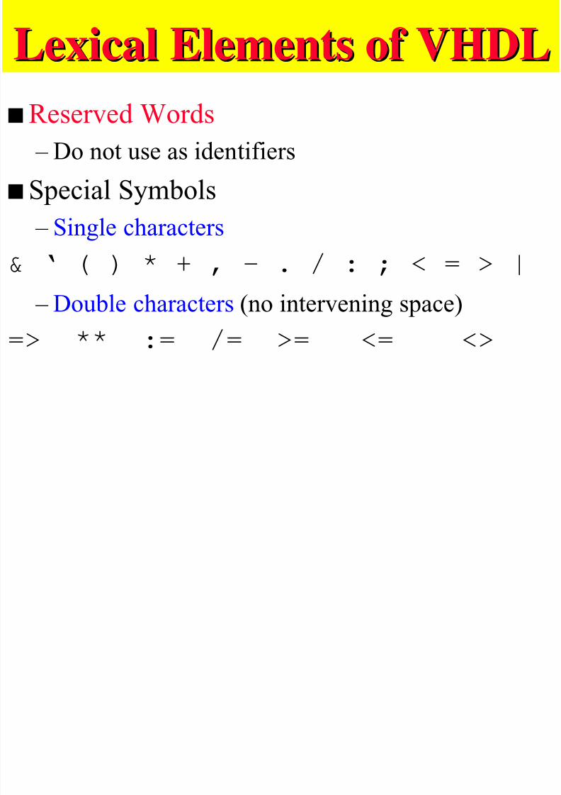
sReserved Words
– Do not use as identifierss Special Symbols
– Single characters& ‘ ( ) * + , - . / : ; < = > |
– Double characters (no intervening space)
=> ** := /= >= <= <>
Lexical Elements of VHDLLexical Elements of VHDL

7/27/2019 VHDL LECTURE SLIDES.pdf
http://slidepdf.com/reader/full/vhdl-lecture-slidespdf 50/90
Lexical Elements of VHDLLexical Elements of VHDL
s Numbers
– Underlines are NOT significant( 10#8_192 )
– Exponential notation allowed ( 46e5 , 98.6E+12 )
– Integer Literals ( 12 )» Only positive numbers; negative numbers are
preceded by unary negation operator
» No radix pointCopyright 1997, KJH
Lexical Elements of VHDLLexical Elements of VHDL

7/27/2019 VHDL LECTURE SLIDES.pdf
http://slidepdf.com/reader/full/vhdl-lecture-slidespdf 51/90
Lexical Elements of VHDLLexical Elements of VHDL
– Real Literals ( 23.1 )
»Always include decimal point»Radix point must be preceded and followed by
at least one digit. – Radix ( radix # number expressed in radix)
»Any radix from binary ( 2 ) to hexadecimal (16 )
»Numbers in radices > 10 use letters a-f for
10-15.
Lexical Elements of VHDLLexical Elements of VHDL

7/27/2019 VHDL LECTURE SLIDES.pdf
http://slidepdf.com/reader/full/vhdl-lecture-slidespdf 52/90
Lexical Elements of VHDLLexical Elements of VHDL
sCharacters
– Any printable character including space enclosed in single quotes ( ‘x‘ )
s
Bit Strings – B for binary ( b”0100_1001” )
– O for Octal ( o”76443” ) – X for hexadecimal ( x”FFFE_F138” )
Characters, bits strings and strings are not thesame thing!
VHDL SyntaxVHDL S ntax

7/27/2019 VHDL LECTURE SLIDES.pdf
http://slidepdf.com/reader/full/vhdl-lecture-slidespdf 53/90
VHDL SyntaxVHDL S ntaxsExtended Backus-Naur Form (EBNF)
– Language divided into syntactic categories – Each category has a rule describing how to build a
rule of that category – Syntactic category <= pattern
– “<=“ is read as “...is defined to be...”
Copyright 1997, KJH
VHDL SyntaxVHDL S ntax
7/27/2019 VHDL LECTURE SLIDES.pdf
http://slidepdf.com/reader/full/vhdl-lecture-slidespdf 54/90
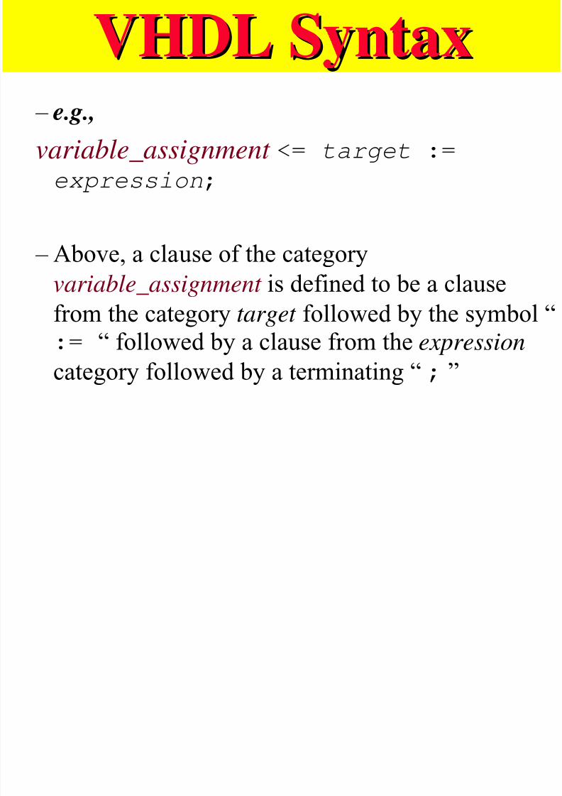
VHDL SyntaxVHDL S ntax – e.g.,
variable_assignment <= target :=expression;
– Above, a clause of the category
variable_assignment is defined to be a clause
from the category target followed by the symbol “:= “ followed by a clause from the expression
category followed by a terminating “ ; ”
VHDL SyntaxVHDL Syntax
7/27/2019 VHDL LECTURE SLIDES.pdf
http://slidepdf.com/reader/full/vhdl-lecture-slidespdf 55/90
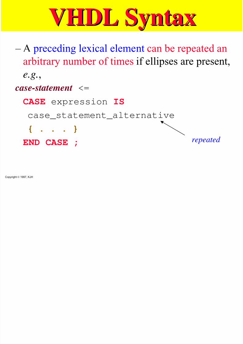
VHDL SyntaxVHDL Syntax – A preceding lexical element can be repeated an
arbitrary number of times if ellipses are present,
e.g.,
case-statement <=
CASE expression IS
case_statement_alternative
{ . . . }END CASE ;
Copyright 1997, KJH
repeated
VHDL SyntaxVHDL Syntax
7/27/2019 VHDL LECTURE SLIDES.pdf
http://slidepdf.com/reader/full/vhdl-lecture-slidespdf 56/90
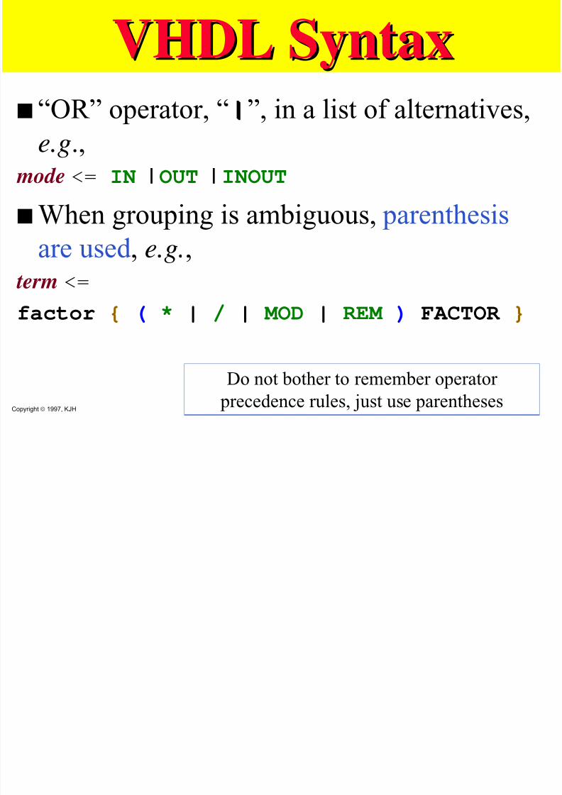
VHDL SyntaxVHDL Syntaxs “OR” operator, “ ||| ”, in a list of alternatives,
e.g., mode <= IN | OUT | INOUT
sWhen grouping is ambiguous, parenthesis
are used , e.g., term <=
factor { ( * | / | MOD | REM ) FACTOR }
Copyright 1997, KJH
Do not bother to remember operator precedence rules, just use parentheses
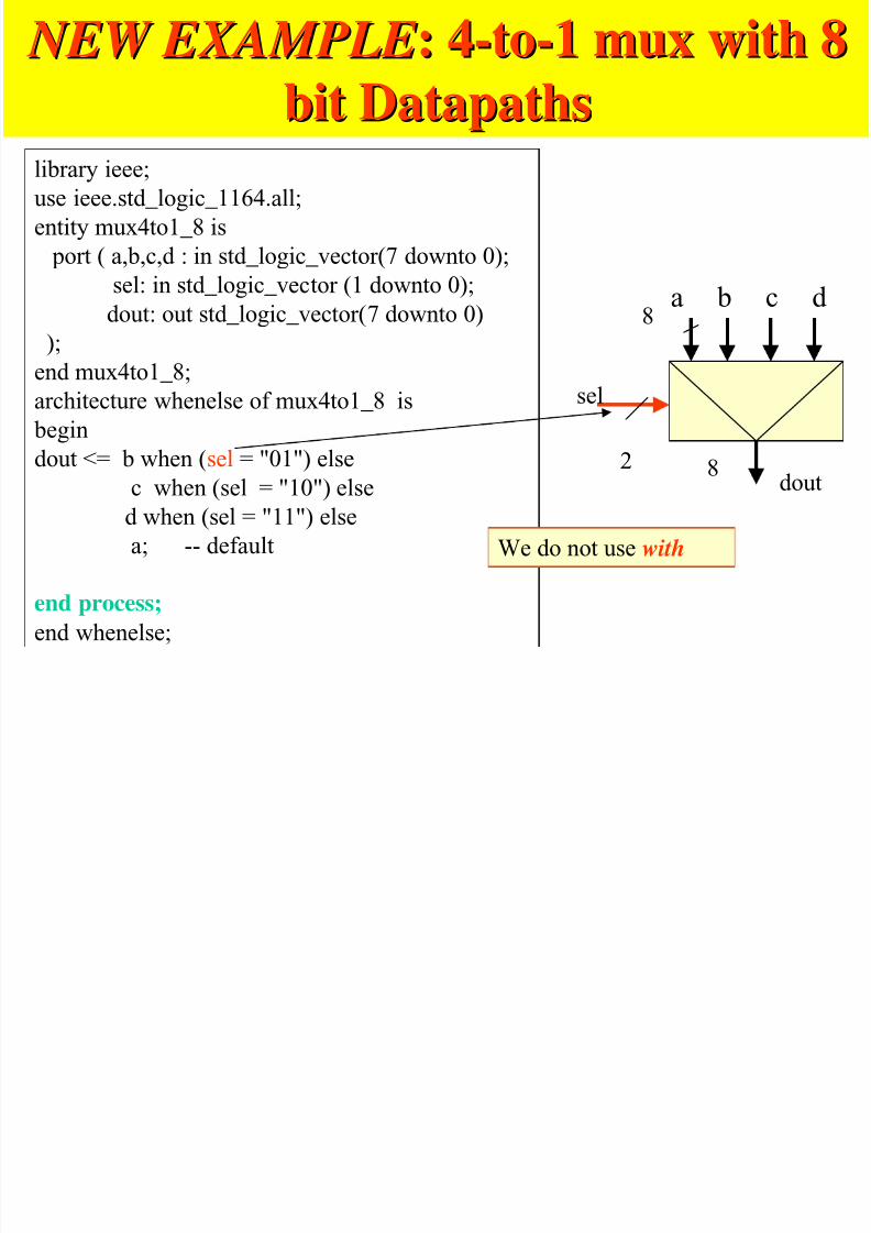
NEW EXAMPLE NEW EXAMPLE: 4-to-1: 4-to-1 muxmux with 8with 8
7/27/2019 VHDL LECTURE SLIDES.pdf
http://slidepdf.com/reader/full/vhdl-lecture-slidespdf 57/90
bitbit DatapathsDatapathslibrary ieee;
use ieee.std_logic_1164.all;
entity mux4to1_8 is
port ( a,b,c,d : in std_logic_vector(7 downto 0);
sel: in std_logic_vector (1 downto 0);
dout: out std_logic_vector(7 downto 0)
);
end mux4to1_8;
architecture whenelse of mux4to1_8 is
begin
dout <= b when (sel = "01") elsec when (sel = "10") else
d when (sel = "11") else
a; -- default
end process;
end whenelse;
8
sel
We do not use with
dout82
a b c d
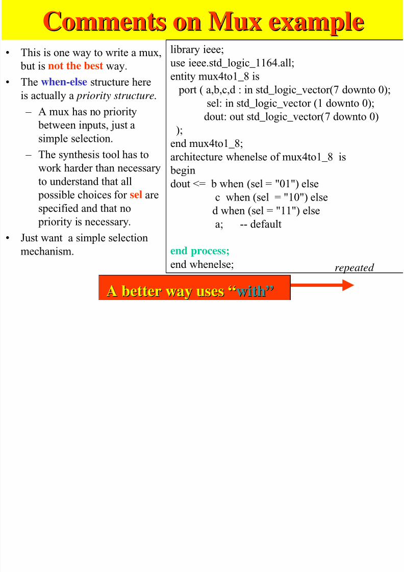
Comments onComments on MuxMux exampleexample
7/27/2019 VHDL LECTURE SLIDES.pdf
http://slidepdf.com/reader/full/vhdl-lecture-slidespdf 58/90
• This is one way to write a mux,
but is not the best way.
• The when-else structure here
is actually a priority structure.
– A mux has no priority between inputs, just a
simple selection.
– The synthesis tool has to
work harder than necessaryto understand that all
possible choices for sel are
specified and that no
priority is necessary.
• Just want a simple selection
mechanism.
library ieee;
use ieee.std_logic_1164.all;entity mux4to1_8 is
port ( a,b,c,d : in std_logic_vector(7 downto 0);
sel: in std_logic_vector (1 downto 0);
dout: out std_logic_vector(7 downto 0));
end mux4to1_8;
architecture whenelse of mux4to1_8 is
begin
dout <= b when (sel = "01") else
c when (sel = "10") else
d when (sel = "11") else
a; -- default
end process;
end whenelse;
A better way uses “A better way uses “with”with”repeated
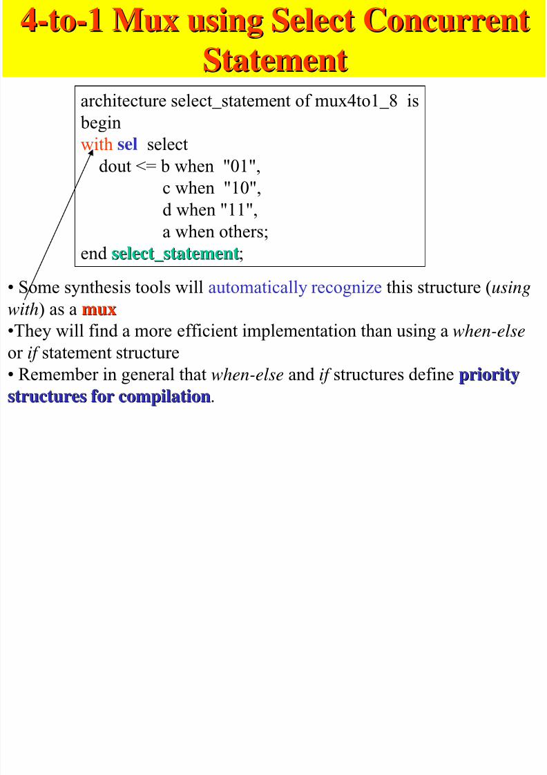
4-to-14-to-1 MuxMux using Select Concurrentusing Select Concurrent
StatementStatement
7/27/2019 VHDL LECTURE SLIDES.pdf
http://slidepdf.com/reader/full/vhdl-lecture-slidespdf 59/90
StatementStatementarchitecture select_statement of mux4to1_8 is
begin
with sel selectdout <= b when "01",
c when "10",
d when "11",
a when others;
end select_statementselect_statement;
• Some synthesis tools will automatically recognize this structure (usingwith) as a muxmux
•They will find a more efficient implementation than using a when-else
or if statement structure
• Remember in general that when-else and if structures define prioritypriority
structures for compilationstructures for compilation.
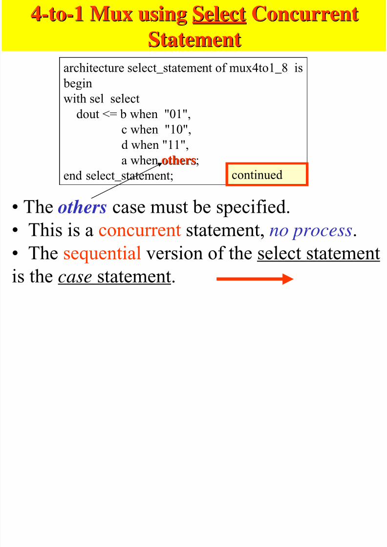
4-to-14-to-1 MuxMux usingusing SelectSelect ConcurrentConcurrent
StatementStatement
7/27/2019 VHDL LECTURE SLIDES.pdf
http://slidepdf.com/reader/full/vhdl-lecture-slidespdf 60/90
StatementStatement
architecture select_statement of mux4to1_8 is
begin
with sel select
dout <= b when "01",
c when "10",
d when "11",
a when othersothers;end select_statement;
• The others case must be specified.• This is a concurrent statement, no process.
• The sequential version of the select statementis the case statement.
continued
4-to-14-to-1 MuxMux usingusing CaseCase SequentialSequential

7/27/2019 VHDL LECTURE SLIDES.pdf
http://slidepdf.com/reader/full/vhdl-lecture-slidespdf 61/90
StatementStatementarchitecture select_statement of mux4to1_8 is
begin
process (a, b, c, d, sel)begin
case sel is
when "01" => dout <= b ;
when "10" => dout <= c;when "11" => dout <= d;
when others => dout <= a;
end case;
end process;end select_statement;
•There can be multiple
statements for each case;• only one statement is
needed for each case in this
example.
Uses process, it is sequential
Concurrent => use select
Sequential => use case
Pay attention to this arrow, how it
is directed
Logical Shift Left by 1Logical Shift Left by 1
7/27/2019 VHDL LECTURE SLIDES.pdf
http://slidepdf.com/reader/full/vhdl-lecture-slidespdf 62/90
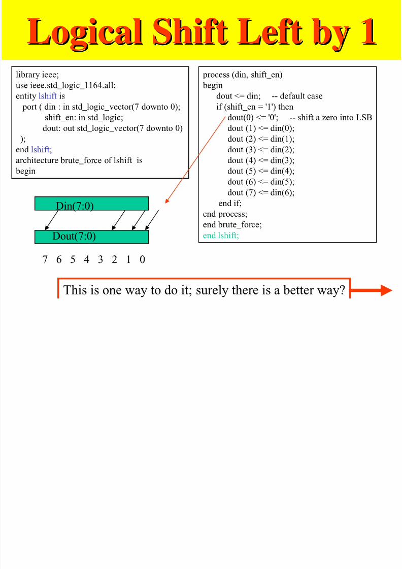
g yg ylibrary ieee;
use ieee.std_logic_1164.all;
entity lshift is
port ( din : in std_logic_vector(7 downto 0);
shift_en: in std_logic;
dout: out std_logic_vector(7 downto 0)
);
end lshift;
architecture brute_force of lshift is
begin
process (din, shift_en)
begin
dout <= din; -- default case
if (shift_en = '1') then
dout(0) <= '0'; -- shift a zero into LSB
dout (1) <= din(0);
dout (2) <= din(1);
dout (3) <= din(2);
dout (4) <= din(3);
dout (5) <= din(4);
dout (6) <= din(5);
dout (7) <= din(6);
end if;
end process;end brute_force;
end lshift;
This is one way to do it; surely there is a better way?
Din(7:0)
Dout(7:0)
7 6 5 4 3 2 1 0
Logical Shift Left by 1 (better way)Logical Shift Left by 1 (better way)
7/27/2019 VHDL LECTURE SLIDES.pdf
http://slidepdf.com/reader/full/vhdl-lecture-slidespdf 63/90
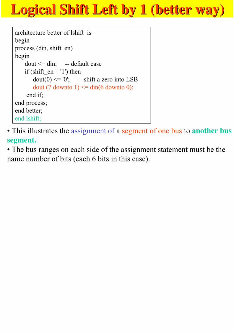
architecture better of lshift is begin
process (din, shift_en)
begin
dout <= din; -- default caseif (shift_en = '1') then
dout(0) <= '0'; -- shift a zero into LSB
dout (7 downto 1) <= din(6 downto 0);
end if;end process;
end better;
end lshift;
• This illustrates the assignment of a segment of one bus to another bus
segment.
• The bus ranges on each side of the assignment statement must be the
name number of bits (each 6 bits in this case).
4 Bit Ripple Carry Adder4 Bit Ripple Carry Adder

7/27/2019 VHDL LECTURE SLIDES.pdf
http://slidepdf.com/reader/full/vhdl-lecture-slidespdf 64/90
A B
S
CiCo
A B
S
CiCo
A B
S
CiCo
A B
S
CiCo Cin
A(0)
Cout
B(0)A(1) B(1)A(2) B(2)A(3) B(3)
C(0)C(1)C(2)C(3)C(4)
Sum(0)Sum(1)Sum(2)Sum(3)
Want to write a VHDL model for a 4 bit ripple carry adder.
Logic equation for each full adder is:
sum <= a xor b xor ci;
co <= (a and b) or (ci and (a or b));
4 Bit Ripple Carry Model4 Bit Ripple Carry Modellibrary ieee;
use ieee std logic 1164 all; full adder 2

7/27/2019 VHDL LECTURE SLIDES.pdf
http://slidepdf.com/reader/full/vhdl-lecture-slidespdf 65/90
use ieee.std_logic_1164.all;
entity adder4bit isport ( a,b: in std_logic_vector(3 downto 0);
cin : in std_logic;
cout: out std_logic;
sum: out std_logic_vector(3 downto 0)
);end adder4bit;
architecture bruteforce of adder4bit is
-- temporary signals for internal carries
signal c : std_logic_vector(4 downto 0); .
beginprocess (a, b, cin, c)
begin
c(0) <= cin;
-- full adder 0
sum(0) <= a(0) xor b(0) xor c(0);c(1) <= (a(0) and b(0)) or (c(0) and (a(0) or b(0)));
-- full adder 1
sum(1) <= a(1) xor b(1) xor c(1);
c(2) <= (a(1) and b(1)) or (c(1) and (a(1) or b(1)));
-- full adder 2
sum(2) <= a(2) xor b(2) xor c(2);c(3) <= (a(2) and b(2)) or (c(2) and
(a(2) or b(2)));
-- full adder 3
sum(3) <= a(3) xor b(3) xor c(3);
c(4) <= (a(3) and b(3)) or (c(3) and (a(3) or b(3)));
cout <= c(4);
end process;
end bruteforce;
••Straight forwardStraight forward
implementation.implementation.
••Nothing wrong with this.Nothing wrong with this.
••However, is there anHowever, is there an easiereasier
way?way?
Not very elegant for longwords, not scalable
4 Bit Ripple Carry Model4 Bit Ripple Carry Model
7/27/2019 VHDL LECTURE SLIDES.pdf
http://slidepdf.com/reader/full/vhdl-lecture-slidespdf 66/90
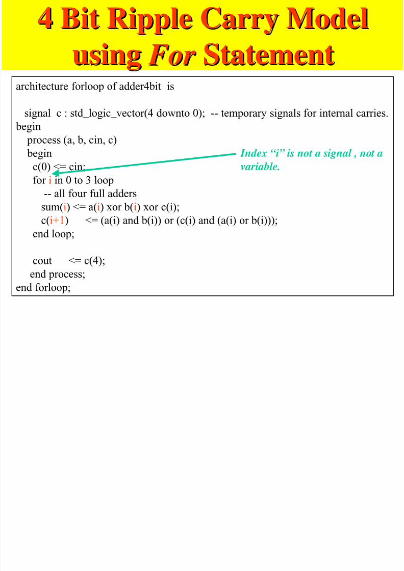
usingusing For For StatementStatementarchitecture forloop of adder4bit is
signal c : std_logic_vector(4 downto 0); -- temporary signals for internal carries. begin
process (a, b, cin, c)
begin
c(0) <= cin;for i in 0 to 3 loop
-- all four full adders
sum(i) <= a(i) xor b(i) xor c(i);
c(i+1) <= (a(i) and b(i)) or (c(i) and (a(i) or b(i)));end loop;
cout <= c(4);
end process;end forloop;
Index “i” is not a signal , not a
variable.
Comments onComments on for-loop for-loop statementstatement
7/27/2019 VHDL LECTURE SLIDES.pdf
http://slidepdf.com/reader/full/vhdl-lecture-slidespdf 67/90
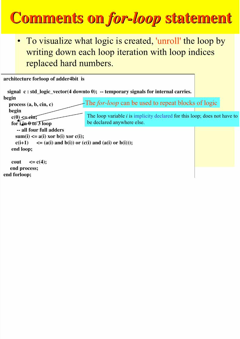
• To visualize what logic is created, 'unroll' the loop by
writing down each loop iteration with loop indices
replaced hard numbers.architecture forloop of adder4bit is
signal c : std_logic_vector(4 downto 0); -- temporary signals for internal carries.
beginprocess (a, b, cin, c)
begin
c(0) <= cin;
for i in 0 to 3 loop
-- all four full adderssum(i) <= a(i) xor b(i) xor c(i);
c(i+1) <= (a(i) and b(i)) or (c(i) and (a(i) or b(i)));
end loop;
cout <= c(4);end process;
end forloop;
The for-loop can be used to repeat blocks of logic
The loop variable i is implicity declared for this loop; does not have to
be declared anywhere else.
VHDL II
7/27/2019 VHDL LECTURE SLIDES.pdf
http://slidepdf.com/reader/full/vhdl-lecture-slidespdf 68/90
VHDL-II
Structural
Modeling
Variables

7/27/2019 VHDL LECTURE SLIDES.pdf
http://slidepdf.com/reader/full/vhdl-lecture-slidespdf 69/90
VariablesVariables
sVariables Exist Only Within an
Architecture – Values of variables cannot be passed to other
entities except through signalssVariables Change Value When They Are
Evaluated. – Signals change at a “later” time
Si nalsSi nals
7/27/2019 VHDL LECTURE SLIDES.pdf
http://slidepdf.com/reader/full/vhdl-lecture-slidespdf 70/90
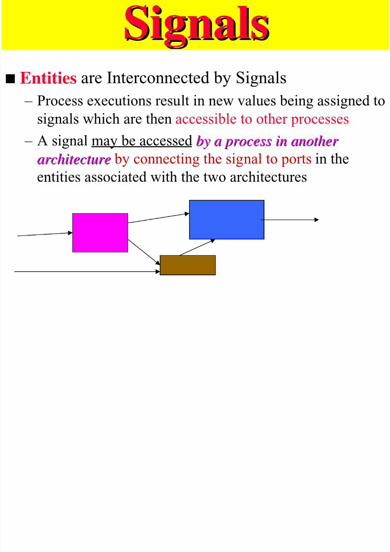
s Entities are Interconnected by Signals
– Process executions result in new values being assigned to
signals which are then accessible to other processes
– A signal may be accessed by a process in another by a process in another
architecturearchitecture by connecting the signal to ports in theentities associated with the two architectures
SignalsSignals
7/27/2019 VHDL LECTURE SLIDES.pdf
http://slidepdf.com/reader/full/vhdl-lecture-slidespdf 71/90
SignalsSignals
s Signals Can Be Declared Internal to anArchitecture to Connect Internal Entities
s
Variables Are Not Appropriate Since They Do NotHave the Temporal Characteristics of Hardware
s Signals Declared Within an Entity Are Not
Available to Other Entities Unless Specified in the
Port Clause of the Entity Declaration.
Entity SyntaxEntit S ntax
7/27/2019 VHDL LECTURE SLIDES.pdf
http://slidepdf.com/reader/full/vhdl-lecture-slidespdf 72/90
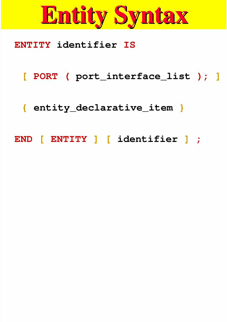
ENTITY identifier IS
[ PORT ( port_interface_list ); ]
{ entity_declarative_item }
END [ ENTITY ] [ identifier ] ;
Entity SyntaxEntity Syntax
7/27/2019 VHDL LECTURE SLIDES.pdf
http://slidepdf.com/reader/full/vhdl-lecture-slidespdf 73/90
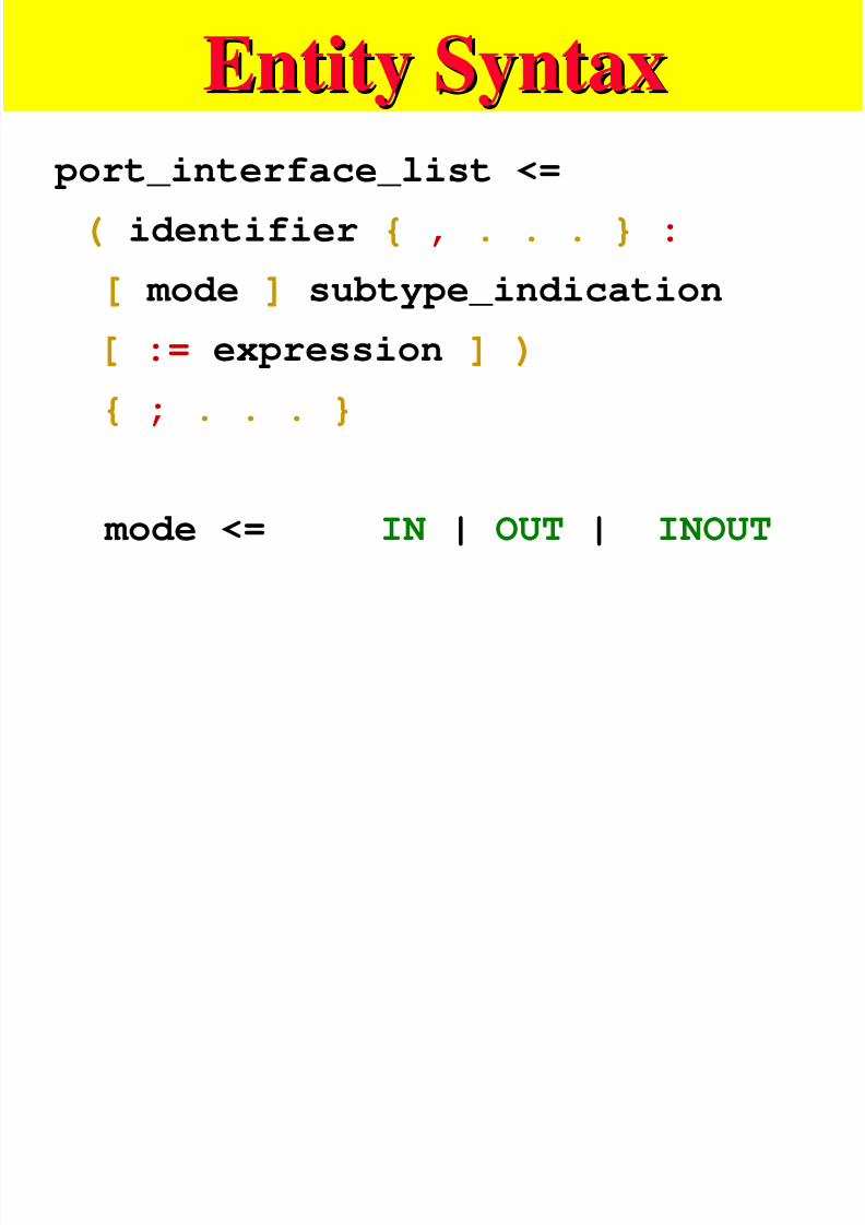
port_interface_list <=
( identifier { , . . . } : [ mode ] subtype_indication
[ := expression ] ) { ; . . . }
mode <= IN | OUT | INOUT
Entity ExampleEntity Example
7/27/2019 VHDL LECTURE SLIDES.pdf
http://slidepdf.com/reader/full/vhdl-lecture-slidespdf 74/90
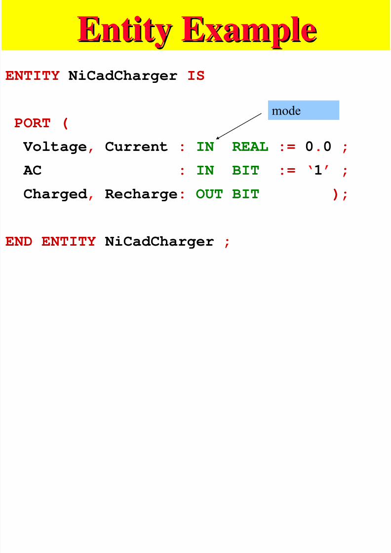
ENTITY NiCadCharger IS
PORT (
Voltage, Current : IN REAL := 0.0 ;
AC : IN BIT := ‘1’ ;
Charged , Recharge: OUT BIT );
END ENTITY NiCadCharger ;
mode
Architecture SyntaxArchitecture Syntax

7/27/2019 VHDL LECTURE SLIDES.pdf
http://slidepdf.com/reader/full/vhdl-lecture-slidespdf 75/90
ARCHITECTURE identifier OF
entity_name IS
{ block_declarative_item }
BEGIN
{ concurrent_statement }
END [ ARCHITECTURE][ identifier ];
Structural ModelStructural Model
7/27/2019 VHDL LECTURE SLIDES.pdf
http://slidepdf.com/reader/full/vhdl-lecture-slidespdf 76/90
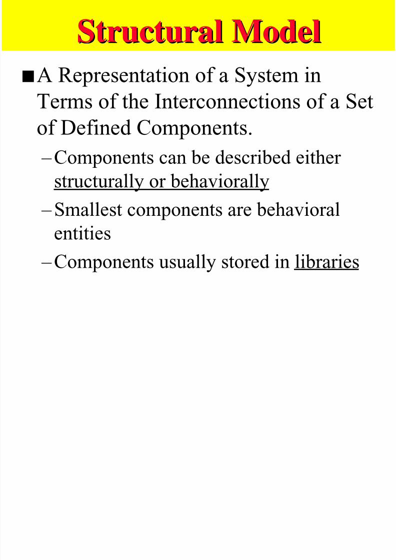
sA Representation of a System in
Terms of the Interconnections of a Setof Defined Components.
–Components can be described either structurally or behaviorally
–Smallest components are behavioralentities
–Components usually stored in libraries
Structural ModelsStructural Models

7/27/2019 VHDL LECTURE SLIDES.pdf
http://slidepdf.com/reader/full/vhdl-lecture-slidespdf 77/90
sComponents Can Be Instantiated As
Concurrent Statements in Architectures – If architecture not specified in statement
»Must be specified later, or »Most recently analyzed architecture used
– Ports can be specified two ways»Positional association
» Named association
Internal Signals in aInternal Signals in a
7/27/2019 VHDL LECTURE SLIDES.pdf
http://slidepdf.com/reader/full/vhdl-lecture-slidespdf 78/90
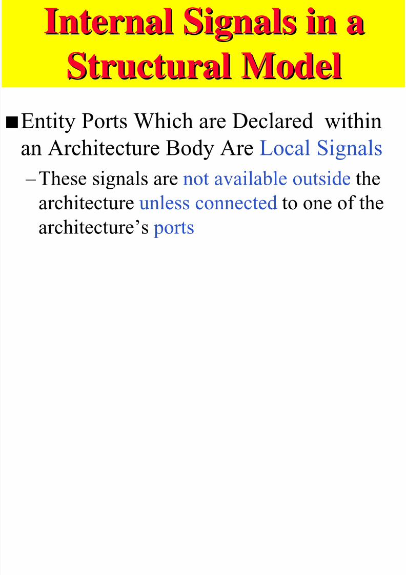
Structural ModelStructural ModelsEntity Ports Which are Declared within
an Architecture Body Are Local Signals
–These signals are not available outside the
architecture unless connected to one of the
architecture’s ports
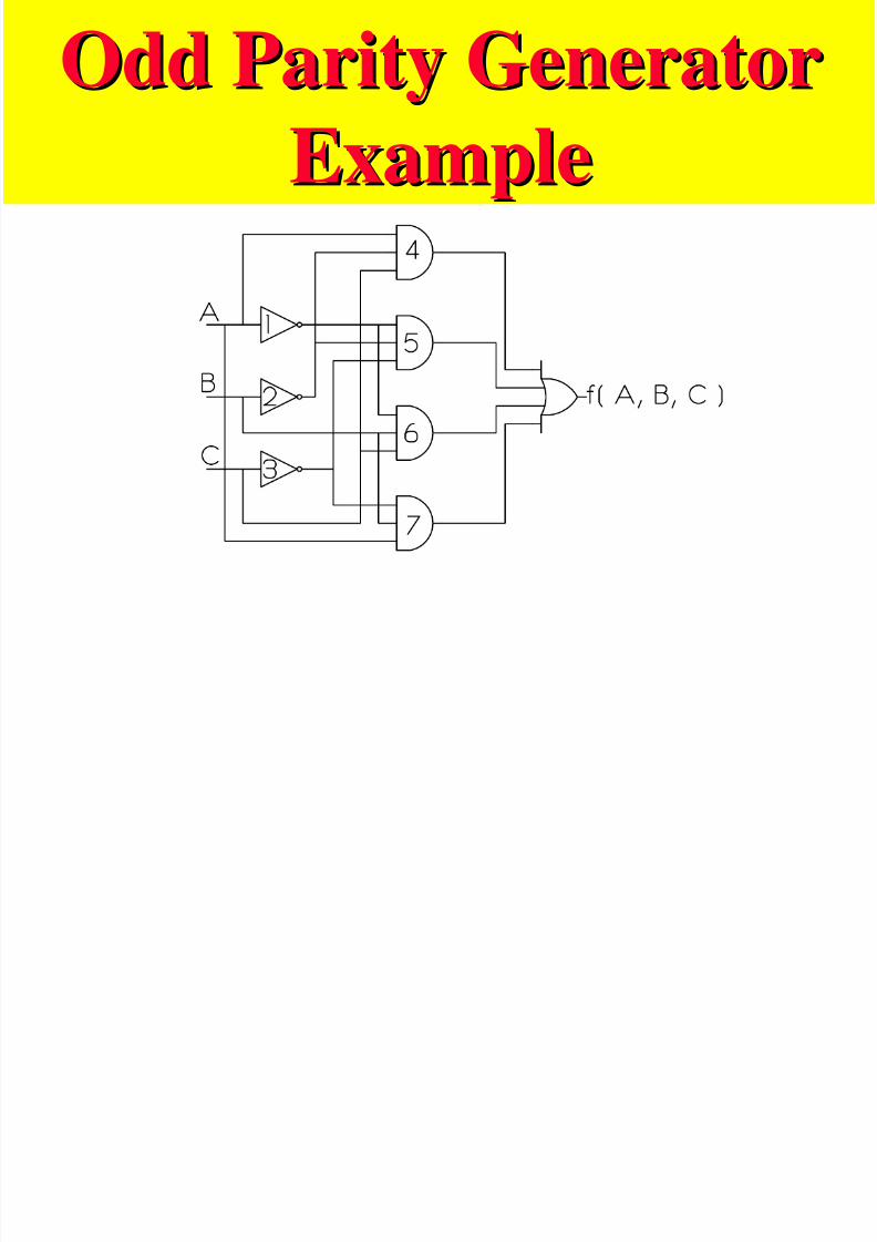
Odd Parity GeneratorOdd Parity Generator
7/27/2019 VHDL LECTURE SLIDES.pdf
http://slidepdf.com/reader/full/vhdl-lecture-slidespdf 79/90
ExampleExample
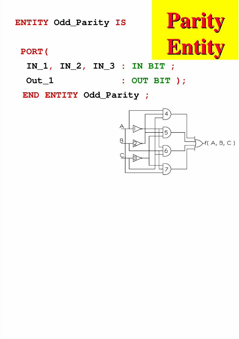
ParityParityENTITY Odd_Parity IS
7/27/2019 VHDL LECTURE SLIDES.pdf
http://slidepdf.com/reader/full/vhdl-lecture-slidespdf 80/90
EntityEntityPORT(
IN_1, IN_2, IN_3 : IN BIT ;Out_1 : OUT BIT );
END ENTITY Odd_Parity ;
Odd Parity Behavior ArchitectureOdd Parity Behavior Architecture

7/27/2019 VHDL LECTURE SLIDES.pdf
http://slidepdf.com/reader/full/vhdl-lecture-slidespdf 81/90
ARCHITECTURE Odd_Parity_B OF
Odd_Parity IS
BEGIN
Out_1 <= ( IN_1 AND NOT IN_2 AND IN_3 ) OR ( NOT IN_1 AND NOT IN_2 AND NOT IN_3 )
OR ( NOT IN_1 AND IN_2 AND IN_3 )
OR ( IN_1 AND IN_2 AND NOT IN_3 )END ARCHITECTURE Odd_Parity_B ;
( ) f A B C ABC ABC ABC ABC odd
, , = + + +
INVERTER Entity andINVERTER Entity and

7/27/2019 VHDL LECTURE SLIDES.pdf
http://slidepdf.com/reader/full/vhdl-lecture-slidespdf 82/90
ArchitectureArchitecture
ENTITY INV IS
PORT(
In_1 : IN BIT ;In_1_Bar : OUT BIT );
END ENTITY INV ;
ARCHITECTURE INV_B OF INV IS
BEGIN
In_1_Bar <= NOT IN_1 ;
END ARCHITECTURE INV_B ;
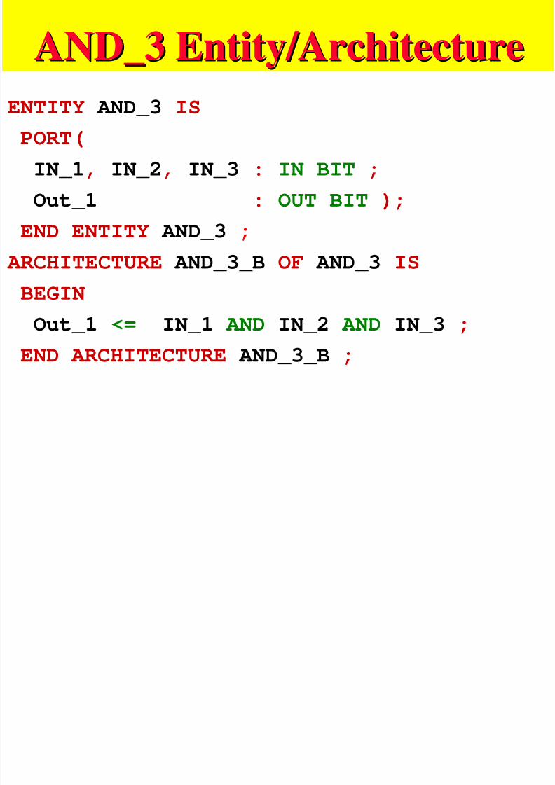
AND_3 Entity/ArchitectureAND_3 Entity/Architecture
7/27/2019 VHDL LECTURE SLIDES.pdf
http://slidepdf.com/reader/full/vhdl-lecture-slidespdf 83/90
ENTITY AND_3 IS
PORT(
IN_1, IN_2, IN_3 : IN BIT ;
Out_1 : OUT BIT );
END ENTITY AND_3 ;ARCHITECTURE AND_3_B OF AND_3 IS
BEGIN
Out_1 <= IN_1 AND IN_2 AND IN_3 ;
END ARCHITECTURE AND_3_B ;
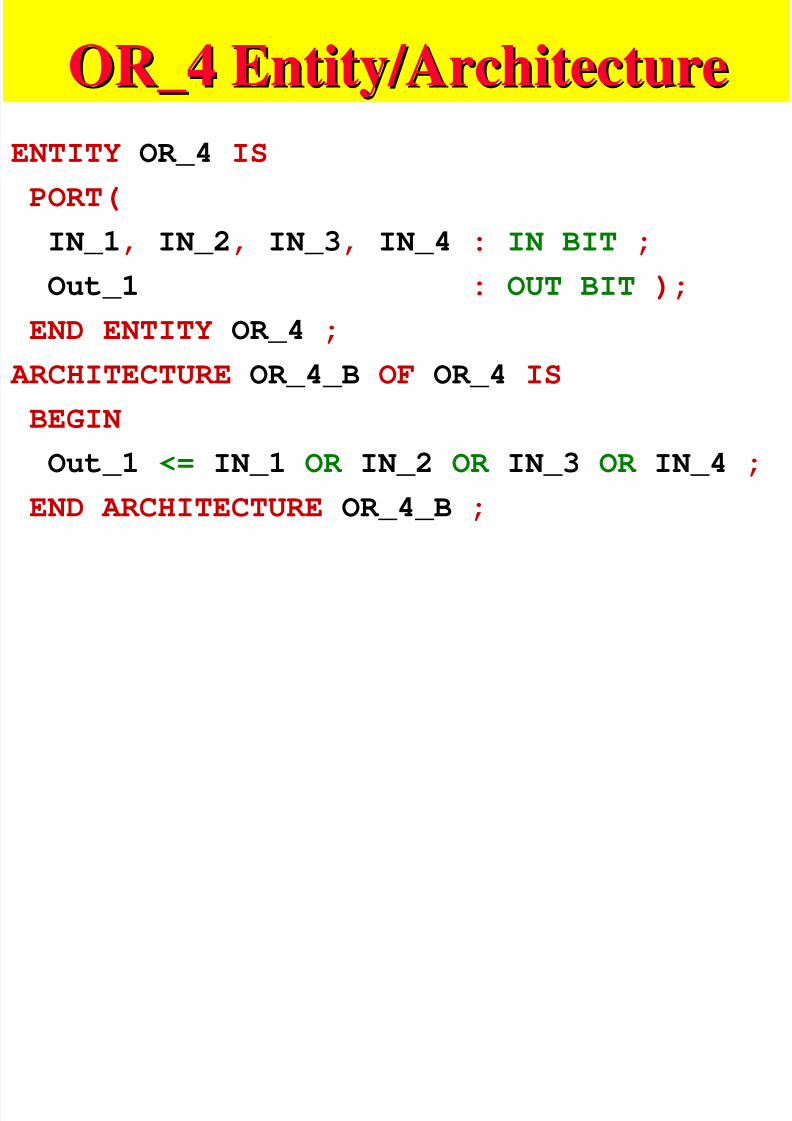
OR_4 Entity/ArchitectureOR_4 Entity/Architecture
7/27/2019 VHDL LECTURE SLIDES.pdf
http://slidepdf.com/reader/full/vhdl-lecture-slidespdf 84/90
ENTITY OR_4 IS
PORT(
IN_1, IN_2, IN_3, IN_4 : IN BIT ;
Out_1 : OUT BIT );
END ENTITY OR_4 ;ARCHITECTURE OR_4_B OF OR_4 IS
BEGIN
Out_1 <= IN_1 OR IN_2 OR IN_3 OR IN_4 ;
END ARCHITECTURE OR_4_B ;
Odd Parity Structural ArchitectureOdd Parity Structural Architecture
7/27/2019 VHDL LECTURE SLIDES.pdf
http://slidepdf.com/reader/full/vhdl-lecture-slidespdf 85/90
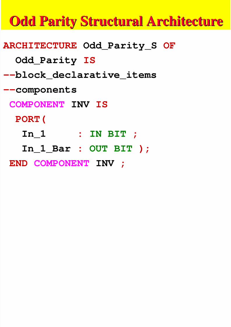
ARCHITECTURE Odd_Parity_S OF
Odd_Parity IS
-- block_declarative_items
--components
COMPONENT INV IS
PORT(
In_1 : IN BIT ;
In_1_Bar : OUT BIT );
END COMPONENT INV ;
Odd Parity Structural ArchitectureOdd Parity Structural Architecture
7/27/2019 VHDL LECTURE SLIDES.pdf
http://slidepdf.com/reader/full/vhdl-lecture-slidespdf 86/90
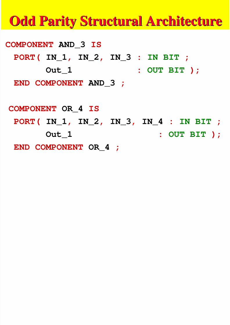
COMPONENT AND_3 IS
PORT( IN_1, IN_2, IN_3 : IN BIT ;
Out_1 : OUT BIT );
END COMPONENT AND_3 ;
COMPONENT OR_4 IS
PORT( IN_1, IN_2, IN_3, IN_4 : IN BIT ;
Out_1 : OUT BIT );
END COMPONENT OR_4 ;
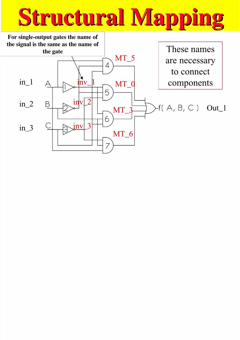
Structural MappingStructural MappingF i l h f
7/27/2019 VHDL LECTURE SLIDES.pdf
http://slidepdf.com/reader/full/vhdl-lecture-slidespdf 87/90
inv_1
MT_5
inv_2
inv_3
in_2
in_1
in_3
MT_0
MT_3
MT_6
Out_1
For single-output gates the name of the signal is the same as the name of
the gate These names
are necessary
to connectcomponents
Odd Parity Structural ArchitectureOdd Parity Structural Architecture
7/27/2019 VHDL LECTURE SLIDES.pdf
http://slidepdf.com/reader/full/vhdl-lecture-slidespdf 88/90
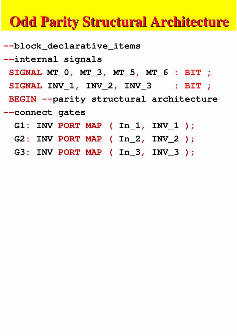
-- block_declarative_items
--internal signals
SIGNAL MT_0, MT_3, MT_5, MT_6 : BIT ;
SIGNAL INV_1, INV_2, INV_3 : BIT ;
BEGIN -- parity structural architecture--connect gates
G1: INV PORT MAP ( In_1, INV_1 );
G2: INV PORT MAP ( In_2, INV_2 );
G3: INV PORT MAP ( In_3, INV_3 );
Odd Parity Structural ArchitectureOdd Parity Structural Architecture
7/27/2019 VHDL LECTURE SLIDES.pdf
http://slidepdf.com/reader/full/vhdl-lecture-slidespdf 89/90
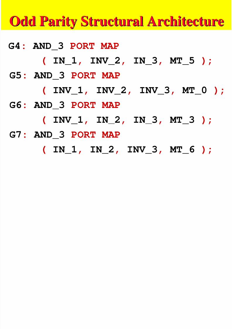
G4: AND_3 PORT MAP
( IN_1, INV_2, IN_3, MT_5 );
G5: AND_3 PORT MAP
( INV_1, INV_2, INV_3, MT_0 );
G6: AND_3 PORT MAP
( INV_1, IN_2, IN_3, MT_3 );
G7: AND_3 PORT MAP
( IN_1, IN_2, INV_3, MT_6 );
Odd Parity Structural ArchitectureOdd Parity Structural Architecture
7/27/2019 VHDL LECTURE SLIDES.pdf
http://slidepdf.com/reader/full/vhdl-lecture-slidespdf 90/90
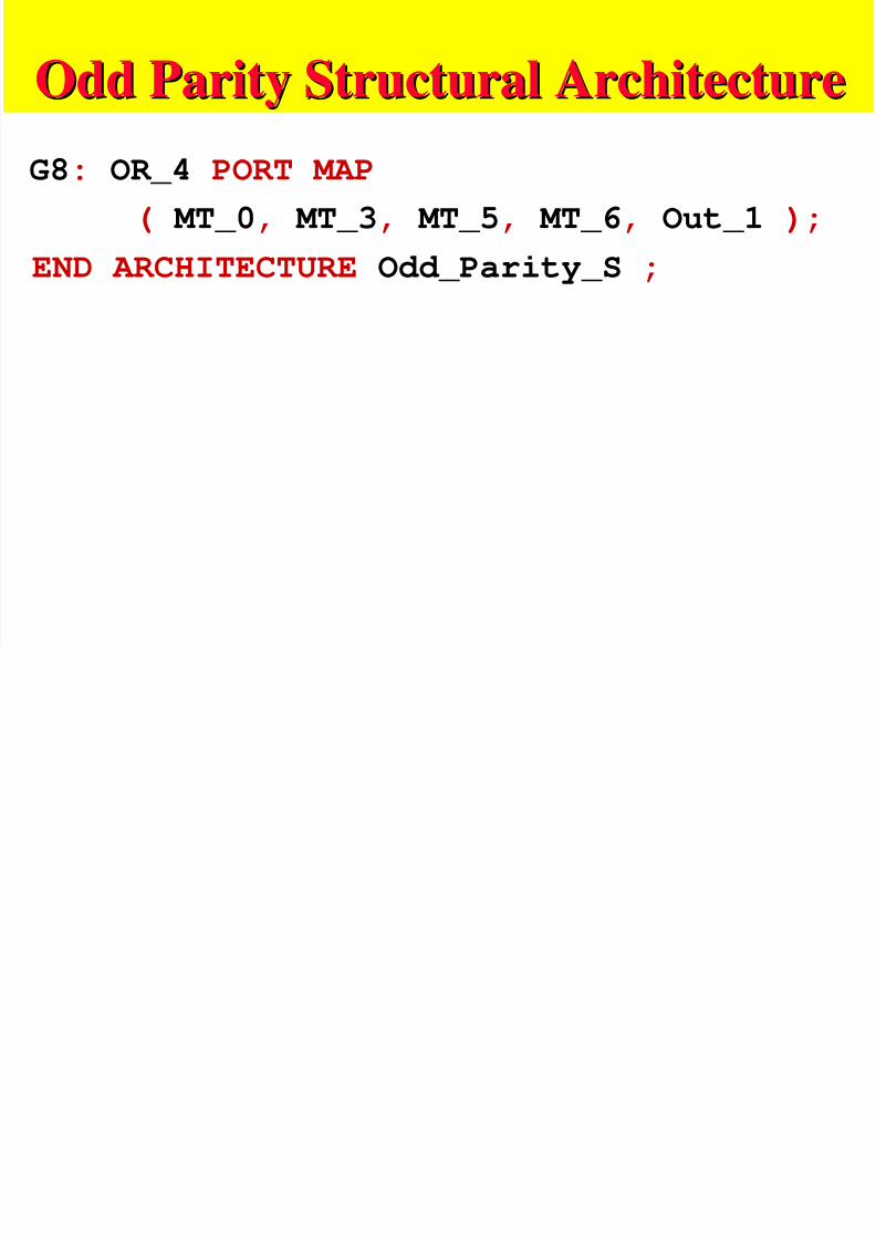
G8: OR_4 PORT MAP
( MT_0, MT_3, MT_5, MT_6, Out_1 );
END ARCHITECTURE Odd_Parity_S ;