lecture 2: introduction to system design, vhdl basics 2 - vhdl basics.pdf · lecture 2:...
TRANSCRIPT
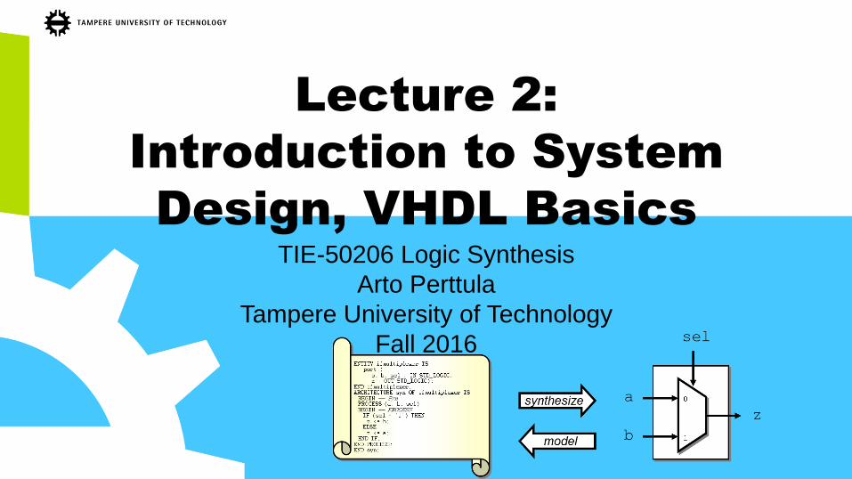
Lecture 2:
Introduction to System
Design, VHDL Basics
TIE-50206 Logic Synthesis
Arto Perttula
Tampere University of Technology
Fall 2016

Contents
• 1. Introduction to System Design
– Abstraction
– Main phases
• 2. VHDL basics
– Entity – the interface
– Architecture – the behavior
– Continues next week
25.10.2016Arto Perttula 2

Acknowledgements
• Prof. Pong P. Chu provided ”official” slides for
the book which is gratefully acknowledged
– See also: http://academic.csuohio.edu/chu_p/
• Most slides were originally made by Ari Kulmala
– and other previous lecturers (Teemu Pitkänen, Konsta
Punkka, Mikko Alho, Erno Salminen…)
25.10.2016Arto Perttula 3

1. INTRODUCTION TO
SYSTEM DESIGN
1a. Representation (View) and Abstraction
25.10.2016Arto Perttula 4

Examples of Different Views
• View: different perspectives of a system
1. Behavioral view:
– Describe functionalities and I/O behavior
– Treat system as a black box
2. Structural view:
– Describe the internal implementation
(components and interconnections)
– Essentially a block diagram (or schematic)
3. Physical view:
– Add more info to structural view: component size, component locations, routing wires
– E.g., layout of a print circuit board
25.10.2016Arto Perttula 5

Examples of Different Views (2)
25.10.2016Arto Perttula 6
2. Structural 3. Physical1. Behavioral
inputs:
button0_in, button1_in
...
outputs:
led0_out
audio_out
...
Function:
When user presses
button1, then...
When...
higher abstraction

Complexity Management
• Q: How to manage complexity for a chip with 10 million transistors?
• A: Abstraction – a simplified model of a system
– Show the selected features
– Ignore many details
• E.g., timing of an inverter
25.10.2016Arto Perttula 7

Levels of Abstraction in HDL
1. Transistor level, lowest abstraction
2. Gate level
3. Register transfer level (RTL)
– Typical level nowadays in addition to structural
4. Behavioral (Processor) level, highest abstraction
5. (Manager view: everything works just by snapping fingers…)
• Characteristics of each level
– Basic building blocks
– Signal representation
– Time representation
– Behavioral representation
– Physical representation
25.10.2016Arto Perttula 8

Summary of Abstractions
This course focuses on RTL
25.10.2016Arto Perttula 9
adder
divide FSM
LevelExample
blockCourse
ELT-
xxxx
DigiPer.
Dig Suunn
Dig.Suunn.
this
System
design
CPU MEM
I/O ACC
NOC
SWbehavioral

Behavioral Description
• An untimed algorithm description with no notation of time or registers (or
even interface)
• The tools automatically place the registers according to the constraints set
by the designer
• E.g., FFT described in Matlab/C
• The designer gives constraints to a behavioral synthesis tool
– Maximum latency, clock frequency, throughput, area
– Interface
• The tool explores the design space and creates the timing-aware circuit
• Not very well supported yet
25.10.2016Arto Perttula 10

Register-Transfer Level (RTL)
• Typically, HW description languages use RT level
• The idea is to represent the combinational logic before registers
– The logic between registers, i.e., between register transfers
• The registers are ”implied” not explicitly defined in VHDL
– Synchronous processes imply registers and are covered later lectures
• Combinatorial logic is created by synthesis tool and depends on
1. Right-hand-side of the signal assignment (e.g. x_r <= a+b;)
2. Preceding control structures (if sel=’1’, for(i=0;i<9;i++)…)
11
Explicitly defined
D Q
inp
uts Comb.
logic
Implied by coding style
x_r
Note that you can
create purely
combinatorial logic
using RTL
abstraction
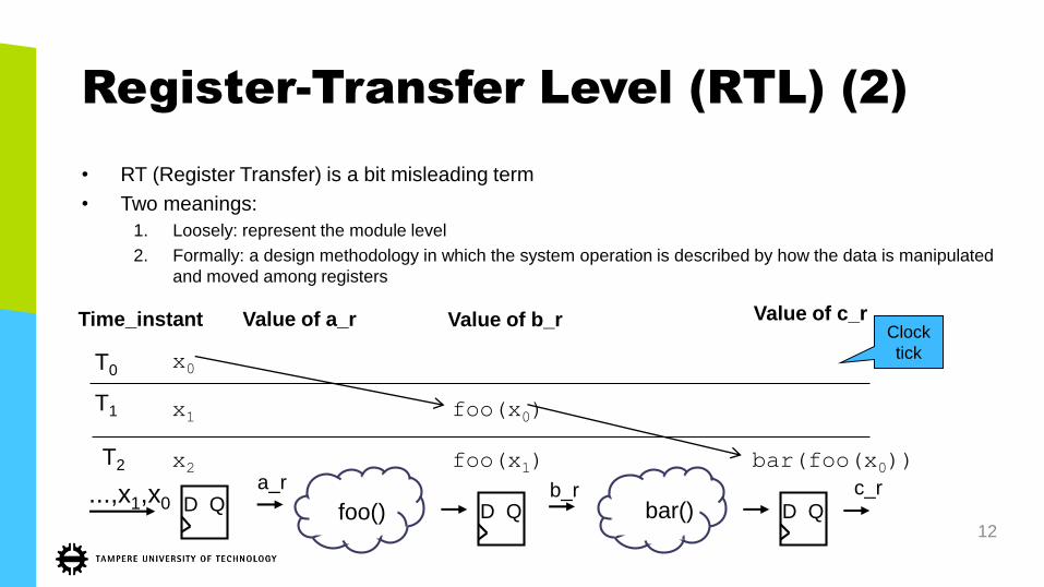
Register-Transfer Level (RTL) (2)
• RT (Register Transfer) is a bit misleading term
• Two meanings:
1. Loosely: represent the module level
2. Formally: a design methodology in which the system operation is described by how the data is manipulated
and moved among registers
12D Q D Q
x0
foo() bar()
x1 foo(x0)T1
T0
...,x1,x0 D Q
T2 bar(foo(x0))foo(x1)a_r b_r c_r
x2
Clock
tick
Time_instant Value of a_r Value of b_r Value of c_r

Key for Success: Hierarchy
25.10.2016Arto Perttula 13
• All systems are designed and implemented hierarchically
• The same component can bereplicated and used in manyproducts
• Usually only knowledge of external behavior is required, not the internals

Structural VHDL Description
• Circuit is described in terms of its components
• High-level block diagram
• Black-box components, modularity
• For large circuits, low-level descriptions quicky become impractical
• Hierarchy is very essential to manage complex designs
Arto Perttula 14
Syntax:
Corresponds to the entity
Parameters
Ports

Example
• A hierarchical two-digit decimal counter
– pulse=1 when q is 9
– p100=1 when both q_ten and q_one are 9
– However, if en goes 0 when q=9, something strange happens…
• Let’s concentrare on the structure…
15
Single
counter
component
Top-level block diagram, ”hundred_counter”

Example Implemented in VHDL
25.10.2016Arto Perttula 16
Top-level entity
”We will use an existingcomponent calleddec_counter”
Internal signals
Instantiate the counters as in schematic and connect the signals to ports. Notation for mapping ports:<port name in the component> => <signal name or port in higherlevel>

1b. Development Tasks
25.10.2016Arto Perttula 17
1. INTRODUCTION TO
SYSTEM DESIGN

System Development
• Developing a digital system is a refining and validating process
• Main tasks:
25.10.2016Arto Perttula 18
I. requirements
capture, specification
II. design, synthesis
III. physical design
IV. fabrication, testing
I-III. verific
atio
n
time

I. Specification
• Capture the
1. use cases, requirements
2. non-functional requirements (performance, cost, power consumption,
silicon area)
• Usually informal, natural language (English, Finnish) completed with
tables and illustrations
– Formal methods are being studied and their importance will increase
25.10.2016Arto Perttula 19

II. Design, Synthesis
• A refinement process that realizes a description with components from the lower
abstraction level
– Manual/automated
• The resulting description is a structural view in the lower abstraction level
– A synthesis from VHDL code obtains netlist (gates and flip-flops)
– Estimates the size, maximum frequency and power consumption
• Type of synthesis:
– High-level synthesis
– RT level synthesis
– Gate level synthesis
– Technology mapping
• Emphasis of this course
25.10.2016Arto Perttula 20
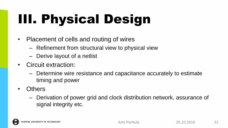
III. Physical Design
• Placement of cells and routing of wires
– Refinement from structural view to physical view
– Derive layout of a netlist
• Circuit extraction:
– Determine wire resistance and capacitance accurately to estimate
timing and power
• Others
– Derivation of power grid and clock distribution network, assurance of
signal integrity etc.
25.10.2016Arto Perttula 21

I-III. Verification
• Check whether a design meets the specification and performance
goals
• Concern the correctness of the initial design and the refinement
processes
• Two aspects
1. Functionality (e.g., is the answer 42?)
2. Non-functional (e.g., performance)
• Takes ~40-80% of design time
25.10.2016Arto Perttula 22

I-III. Methods of Verification
1. Simulation
– Spot check: cannot verify the absence of errors
– Can be computationally intensive
2. Hardware emulation with reconfigurable HW
– Almost real-time, connection to external devices
3. Timing analysis
– Just check the worst case delay, automated
4. Formal verification
– Apply formal mathematical techniques to determine certain properties, applicable only in small scale
– E.g., equivalence checking between two models
5. Specification/code review
– Explain the design/specification to others and they comment it
– Surprisingly powerfull!
25.10.2016Arto Perttula 23

IV. Testing
• Testing is the process of detecting physical defects of a die or a package
occured at the time of manufacturing
– Testing and verification are different tasks in chip design
• Difficult for large circuit
– Must add auxiliary testing circuit into design
– E.g., built-in self test (BIST), scan chain etc.
– Some tests with specialized test-SW running on chip
• Locating the fault is not always needed
– Faulty chips simply discarded
• Basic tests are done at wafer-level
– Sub-set of tests also for packaged chips
25.10.2016Arto Perttula 24

1c. Development Flow
25.10.2016Arto Perttula 25
1. INTRODUCTION TO
SYSTEM DESIGN

EDA Software
• EDA (Electronic Design Automation) software can automate many tasks
• Mandatory for success together with re-use!
• Can software replace human hardware designer? (e.g., C-program to chip)
• Synthesis software
– Should be treated as a tool to perform transformation and local optimization
– Cannot alter the original architecture or convert a poor design into a good one
– See also the so called ”Mead & Conway revolution”
• EDA tools abstraction level in functional description has not increased
significantly since mid-90’s when RT-level gained popularity
– Increased abstraction always causes some penalty in performance, area etc.
when increasing abstraction, but significant improvement in time to design
25.10.2016Arto Perttula 26

Design Flow
• Medium design targeting FPGA
• Circuit up to 50,000 gates
• Note the test bench development at
the same time as RTL (or before
that)
• Large design targeting FPGA needs
also
– Design partition
– More verification
– I/O-verification, external interfaces
synthesis
placement & routing
device programming
FPGAchip
simulation
simulation
simulation/timing
analysis
Synthesis Physical Design Verification
data file process
RTL description
netlist delay file
configuration file
delay file
testbench1 1
23
445
67
8

2a. Basics
25.10.2016Arto Perttula 28
2. VERY HIGH SPEED
INTEGRATED CIRCUIT
HARDWARE DESCRIPTION
LANGUAGE (VHSIC HDL =
VHDL)

Why (V)HDL?
• Interoperability
• Technology independence
• Design reuse
• Several levels of abstraction
• Readability
• Standard language
• Widely supported
Improved productivity
25.10.2016Arto Perttula 29

What Is VHDL?
• VHDL = VHSIC Hardware Description Language
– (VHSIC = Very High Speed IC)
• Design specification language
• Design entry language
• Design simulation language
• Design documentation language
• An alternative to schematics
25.10.2016Arto Perttula 30

A Brief VHDL History
• Developed in the early 1980’s
– For managing design problems that involved large circuits and multiple teams of
engineers
– Originally for documentation, synthesis developed soon after
– Funded by U.S. Department of Defence
• First publicly available version released in 1985
• IEEE standard in 1987 (IEEE 1076-1987)
– IEEE = Institute of Electrical and Electronics Engineers
• An improved version of the language was released in 1994
– IEEE standard 1076-1993
– No major differences to ’87, but some shortcuts added
25.10.2016Arto Perttula 31

VHDL
• Parallel programming language(!) for hardware
– Allows sequential code portions also
• Modular
– Interface specification is separated from the functional specification
• Allows many solutions to a problem
• The coding style matters!
– Different solutions will be slower and/or larger than others
– Save money!
• Case-insensitive language
– Examples (usually) show reserved words in CAPITALS
• Widely used language25.10.2016Arto Perttula 32
example.vhd
Interface
Declarations
Functionality

My First VHDL Example
25.10.2016
Arto Perttula 33
eg1
ENTITY eg1 IS
PORT (
clk : IN STD_LOGIC;
rst_n : IN STD_LOGIC;
a,b : IN STD_LOGIC_VECTOR(1 DOWNTO 0);
both_1_out: OUT STD_LOGIC;
siwa_out : OUT STD_LOGIC
);
END eg1;
ARCHITECTURE rtl OF eg1 IS
SIGNAL c : STD_LOGIC;
BEGIN
both_1_out <= c;
c <= a(0) AND b(0);
PROCESS ( clk, rst_n )
BEGIN
IF rst_n = ‘0’ THEN
siwa_out <= ‘0’;
ELSIF clk‘EVENT AND clk = '1' THEN
IF a = ‘00' THEN
siwa_out <= b(0);
ELSIF a = ‘11' then
siwa_out <= b(1);
ELSE
siwa_out <= ‘0’;
END IF;
END IF;
END PROCESS;
END rtl;
DFF
clk
siwa_out
rst_n
00
01
10
11
both_1_out
b
a
b(1)
’0’
’0’
2
2
b(0)
C

VHDL Environment
34
(Quartus)
(ModelSim)
(Tools used in this course are shown in parentheses)
Physical design
C <= A AND B
Entities – Interfaces
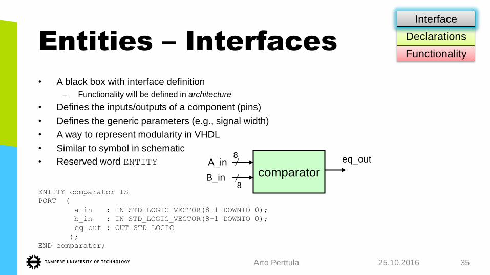
• A black box with interface definition
– Functionality will be defined in architecture
• Defines the inputs/outputs of a component (pins)
• Defines the generic parameters (e.g., signal width)
• A way to represent modularity in VHDL
• Similar to symbol in schematic
• Reserved word ENTITY
ENTITY comparator IS
PORT (
a_in : IN STD_LOGIC_VECTOR(8-1 DOWNTO 0);
b_in : IN STD_LOGIC_VECTOR(8-1 DOWNTO 0);
eq_out : OUT STD_LOGIC
);
END comparator;
25.10.2016Arto Perttula 35
comparator
8
8
A_in
B_in
eq_out
Declarations
Functionality
Interface

Architecture – Internals
• Every entity has at least one architecture
• Architecture specifies the internals of a design unit and is coupled to a
certain entity
– Defines functionality
• One entity can have several architectures
• Architectures can describe design on many levels
– Gate level
– RTL (Register Transfer Level)
– Structural
– Behavioral level
25.10.2016Arto Perttula 36
entity X
XA_in
B_in
C_out
arch 1
”It is
logical
AND”
arch 2
”It is
logical
XOR”
etc.
Declarations
Functionality
Interface

Architecture (2)
• Example:ARCHITECTURE rtl OF comparator IS
BEGIN
eq_out <= ’1’ WHEN (a_in = b_in) ELSE ’0’;
END rtl;
• Two main approaches
1. Define new functionality with control statements, e.g., if-for-case, (rtl), shown
above
2. Instantiate existing components and define interconnections between them(structural)
25.10.2016Arto Perttula 37

Ports
• Provide communication channels (=pins) between the component and its environment
• Each port must have a name, direction and a type
– An entity may omit port declaration, e.g., in test bench
• Port directions:
1. IN: A value of a port can be read inside the component, but cannot be assigned. Multiple reads
of port are allowed.
2. OUT: Assignment can be made to a port, but data from a port cannot be read. Multiple
assignments are allowed.
3. INOUT: Bi-directional, assignments can be made and data can be read. Multiple assignments
are allowed. (not recommended inside a chip)
4. BUFFER: An out port with read capability. May have at most one assignment (not recommended)
25.10.2016Arto Perttula 38
Declarations
Functionality
Interface

Signals
• Used for communication inside the architecture, carry data
– Ports behave like signals
• Can be interpreted as
a) Wires (connecting logic gates)
b) ”wires with memory” (i.e., FF’s, latches etc.)
• VHDL allows many types of signals
– Bit vectors, integers, even multidimensional arrays and records
• Declared in the architecture body’s declaration section
• Signal declaration:
SIGNAL signal_name : data_type;
• Signal assignment:
signal_name <= new_value;
25.10.2016Arto Perttula 39
Functionality
Interface
Declarations

Other Declarations
• Functions, procedures (subprograms)
– Much like in conventional programming languages
• Component declaration
– ”We will use an adder which looks like this”
• Configuration
– ”We will use exactly this adder component instead of that other
one”
– Binds certain architecture to the component instance
25.10.2016Arto Perttula 40
Functionality
Interface
Declarations

Libraries And Packages
• Frequently used functions and types can be grouped in a package
• Libraries include several compiled packages and other design units
• Packages typically contain
– Constants
• Like header.h in conventional programming languages
– General-purpose functions
• E.g., Log2(x)
– Design-specigic definitions
• E.g., own data types, records (structs)
25.10.2016Arto Perttula 41
Functionality
Interface
Declarations

Design Units
• Segments of VHDL code that can be compiled separately and stored in a library
• Library = directory of compiled VHDL files
42
entity
declaration
architecture
bodyarchitecture
bodyarchitecture
body
package
declaration
package
body
configuration
declaration
VHDL library
VHDL
source
files
Select an entity or configuration into simulation

Structure of VHDL Entity
• Usually 1 entity plus 1 architecture per file
– File named according to entity
• Architectures contains usually either
a) processes, or
b) instantiations
Arto Perttulaentity_name.vhd
entity declaration:
ports, generics
architecture
arch declarations:
signals,
functions,
types
arch body:
concurrent statements
component instantiations,
processes
(signal assignments,
if-for-case)
in out

Relation Between Circuit And VHDL
25.10.2016
Adder
Multiplier
A
B
C
sel
A : IN
B : IN
Sel : IN
C : OUT
signal add, mul
Components +, *
declaration
Mux realization
Component instantiation
Signal assignments
GENERIC VHDL STRUCTUREExamplesRealization
0
1
add
mul

Even Parity Detection Circuit
• Input: a(2), a(1), a(0)
• Output: even
25.10.2016Arto Perttula 45
Boolean function:
Logic with basic gates:
Truth table:

Even Parity Detection Circuit at Gate-Level VHDL
25.10.2016Arto Perttula 46
Defines packages
that are used in the
design
The interface of a
block ”even_detector”
Input a, 3 bits
Output even, 1 bit
Signals used internally
Functionality of the
block (gate level
representation).
The order of
assigments does
NOT matter here.
p1
p4
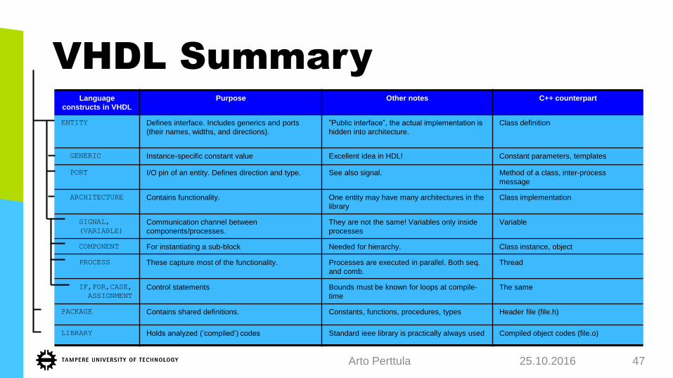
VHDL Summary
25.10.2016Arto Perttula 47
Language
constructs in VHDL
Purpose Other notes C++ counterpart
ENTITY Defines interface. Includes generics and ports
(their names, widths, and directions).
”Public interface”, the actual implementation is
hidden into architecture.
Class definition
GENERIC Instance-specific constant value Excellent idea in HDL! Constant parameters, templates
PORT I/O pin of an entity. Defines direction and type. See also signal. Method of a class, inter-process
message
ARCHITECTURE Contains functionality. One entity may have many architectures in the
library
Class implementation
SIGNAL,
(VARIABLE)
Communication channel between
components/processes.
They are not the same! Variables only inside
processes
Variable
COMPONENT For instantiating a sub-block Needed for hierarchy. Class instance, object
PROCESS These capture most of the functionality. Processes are executed in parallel. Both seq.
and comb.
Thread
IF,FOR,CASE,
ASSIGNMENT
Control statements Bounds must be known for loops at compile-
time
The same
PACKAGE Contains shared definitions. Constants, functions, procedures, types Header file (file.h)
LIBRARY Holds analyzed (’compiled’) codes Standard ieee library is practically always used Compiled object codes (file.o)
EXTRA SLIDES ON VHDL
25.10.2016Arto Perttula 48
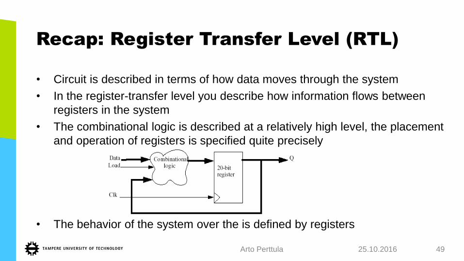
Recap: Register Transfer Level (RTL)
• Circuit is described in terms of how data moves through the system
• In the register-transfer level you describe how information flows between
registers in the system
• The combinational logic is described at a relatively high level, the placement
and operation of registers is specified quite precisely
• The behavior of the system over the is defined by registers
25.10.2016Arto Perttula 49