schneider electric power-style qed-2 low voltage switchboards · pdf file ·...
TRANSCRIPT

Power-Style® QED-2 Low Voltage Switchboards
Catalog2742CT9501R12/09
2009Class 2742
CONTENTS
Description . . . . . . . . . . . . . . . . . . . . . . . . . . . . . . . . . . . . . . . . . . . . . Page
Product Description . . . . . . . . . . . . . . . . . . . . . . . . . . . . . . . . . . . . . . . . . . .3Layout Instructions . . . . . . . . . . . . . . . . . . . . . . . . . . . . . . . . . . . . . . . . . . . .8Incoming Connections . . . . . . . . . . . . . . . . . . . . . . . . . . . . . . . . . . . . . . . . .9Structure and Device Modifications . . . . . . . . . . . . . . . . . . . . . . . . . . . . . . .9Customer Metering (PowerLogic®) . . . . . . . . . . . . . . . . . . . . . . . . . . . . . .10Electronic Trip Systems . . . . . . . . . . . . . . . . . . . . . . . . . . . . . . . . . . . . . . .13Circuit Breakers—Individually Mounted . . . . . . . . . . . . . . . . . . . . . . . . . . .17Circuit Breakers—Group Mounted . . . . . . . . . . . . . . . . . . . . . . . . . . . . . . .22Quick Layout Guide . . . . . . . . . . . . . . . . . . . . . . . . . . . . . . . . . . . . . . . . . .23Fusible Switches—Individually Mounted . . . . . . . . . . . . . . . . . . . . . . . . . .27Fusible Switches—Group Mounted . . . . . . . . . . . . . . . . . . . . . . . . . . . . . .29Utility Metering . . . . . . . . . . . . . . . . . . . . . . . . . . . . . . . . . . . . . . . . . . . . . .30Commercial Multi-Metering (CMM) . . . . . . . . . . . . . . . . . . . . . . . . . . . . . .33QED-2 Quick Connect Generator Switchboards . . . . . . . . . . . . . . . . . . . .35Surge Protective Devices (SPD) . . . . . . . . . . . . . . . . . . . . . . . . . . . . . . . .37Automatic Throwover Systems. . . . . . . . . . . . . . . . . . . . . . . . . . . . . . . . . .38Automatic Transfer Switches . . . . . . . . . . . . . . . . . . . . . . . . . . . . . . . . . . .39Conduit Layout . . . . . . . . . . . . . . . . . . . . . . . . . . . . . . . . . . . . . . . . . . . . .40Seismic Qualifications . . . . . . . . . . . . . . . . . . . . . . . . . . . . . . . . . . . . . . . .41Specifications . . . . . . . . . . . . . . . . . . . . . . . . . . . . . . . . . . . . . . . . . . . . . . .44Secondary Full Load and Short Circuit Currents . . . . . . . . . . . . . . . . . . . .46
Courtesy of Steven Engineering, Inc.-230 Ryan Way, South San Francisco, CA 94080-6370-Main Office: (650) 588-9200-Outside Local Area: (800) 258-9200-www.stevenengineering.com

Courtesy of Steven Engineering, Inc.-230 Ryan Way, South San Francisco, CA 94080-6370-Main Office: (650) 588-9200-Outside Local Area: (800) 258-9200-www.stevenengineering.com
Power-Style® QED-2 Low Voltage SwitchboardsProduct Description General and Application Information
312/2009© 1995–2009 Schneider Electric
All Rights Reserved
Features
• Sections rated to 5,000 A horizontal, 3,000 A vertical
• Single mains to 5,000 A
• Six subdivision mains to 4,000 A
• Individually mounted feeders to 4,000 A
• Suitable for service entrance or distribution
• NEMA Type 1 or Type 3R enclosures
• Front or front and rear accessible
• 91.5 in. (2,324 mm) high with base channels
• Section widths available: 12 in. (305 mm), 24 in. (610 mm), 30 in. (762 mm), 36 in. (914 mm), 42 in. (1,067 mm), 48 in. (1,219 mm), or 54 in. (1,372 mm) wide
• Frame depths available: 24 in. (610 mm), 36 in. (914 mm), 48 in. (1,219 mm), 54 in. (1,372 mm), or 60 in. (1,524 mm)
• Voltage to 600 Vac or 250 Vdc
• Factory assembled
• Hot or cold sequence utility metering
• Customer metering
• Surge protective devices (SPD)
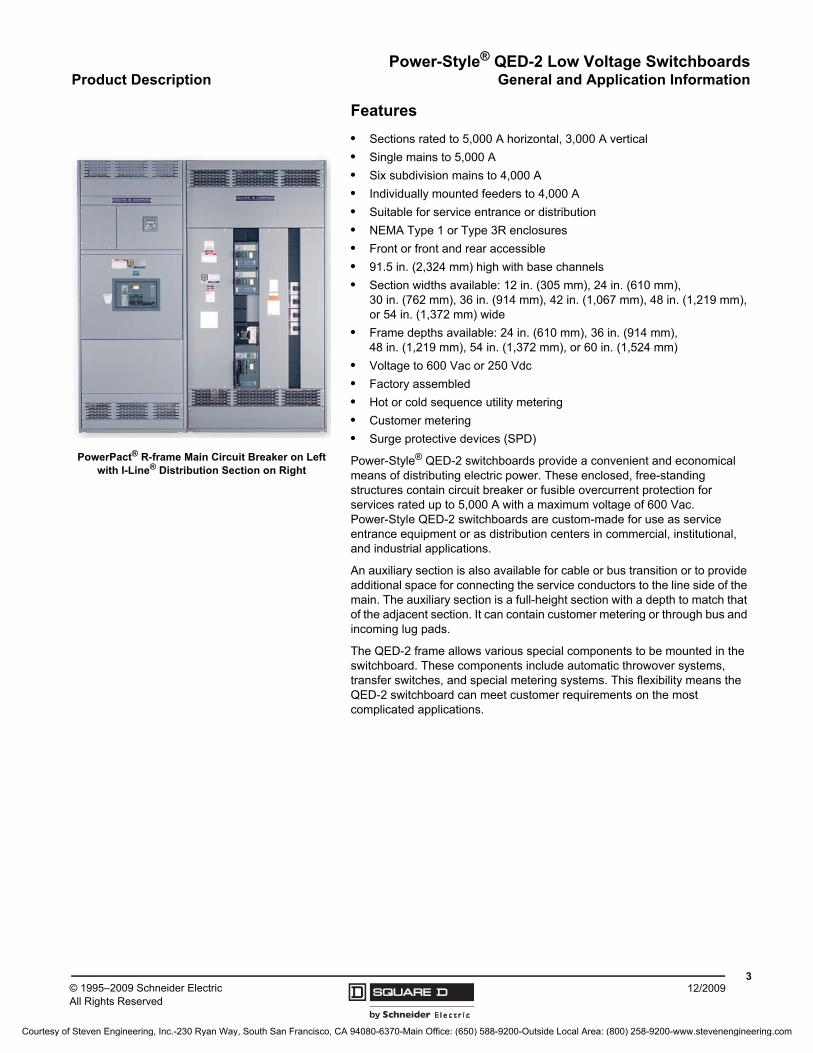
Power-Style® QED-2 switchboards provide a convenient and economical means of distributing electric power. These enclosed, free-standing structures contain circuit breaker or fusible overcurrent protection for services rated up to 5,000 A with a maximum voltage of 600 Vac. Power-Style QED-2 switchboards are custom-made for use as service entrance equipment or as distribution centers in commercial, institutional, and industrial applications.
An auxiliary section is also available for cable or bus transition or to provide additional space for connecting the service conductors to the line side of the main. The auxiliary section is a full-height section with a depth to match that of the adjacent section. It can contain customer metering or through bus and incoming lug pads.
The QED-2 frame allows various special components to be mounted in the switchboard. These components include automatic throwover systems, transfer switches, and special metering systems. This flexibility means the QED-2 switchboard can meet customer requirements on the most complicated applications.
PowerPact® R-frame Main Circuit Breaker on Left with I-Line® Distribution Section on Right
Courtesy of Steven Engineering, Inc.-230 Ryan Way, South San Francisco, CA 94080-6370-Main Office: (650) 588-9200-Outside Local Area: (800) 258-9200-www.stevenengineering.com
Power-Style® QED-2 Low Voltage SwitchboardsGeneral and Application Information Product Description
© 1995–2009 Schneider ElectricAll Rights Reserved
412/2009
Structures
The QED-2 switchboard frame has been designed to provide a sturdy platform on which to build Schneider Electric switchboard products. Individual switchboard sections are built from formed steel channels and angles, then secured together with thread-rolling screws. These thread-rolling screws, when compared with regular self-tapping screws, provide superior torque and strip-out resistant qualities.
Section dimensions are determined by the type, size, quantity, and arrangement of the components and devices being installed.
Each section features a removable one-piece top plate, which makes locating the top conduit entry simple. When extra height is required, Schneider Electric can supply a 12 in. (305 mm) or 24 in. (610 mm) high pullbox. (The pullbox is not available with NEMA Type 3R enclosures.)
All covers, doors, and frames are made of formed steel for extra rigidity. A deep front corner channel and side plate covers the sides. The back is covered with removable plates that have formed edges. All covers are secured with slot/hex head thread rolling screws which greatly minimize the chances of thread strip-out.
The standard paint finish on all Power-Style QED-2 switchboards is an ANSI #49 medium light gray baked enamel over an iron phosphate pretreatment. Non-standard finishes are an available option when specified.
QED-2 switchboards are available in either NEMA Type 1 indoor or Type 3R outdoor enclosures.
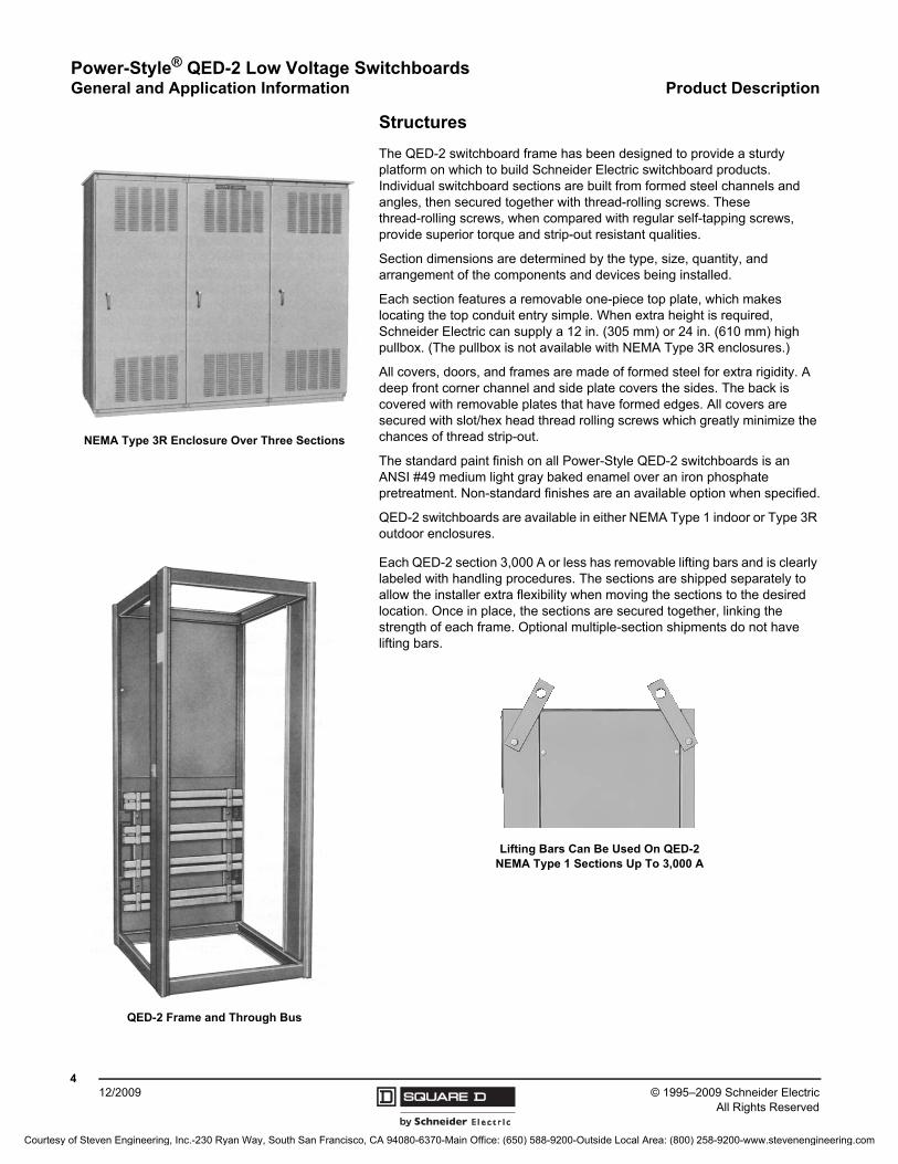
Each QED-2 section 3,000 A or less has removable lifting bars and is clearly labeled with handling procedures. The sections are shipped separately to allow the installer extra flexibility when moving the sections to the desired location. Once in place, the sections are secured together, linking the strength of each frame. Optional multiple-section shipments do not have lifting bars.
NEMA Type 3R Enclosure Over Three Sections
QED-2 Frame and Through Bus
Lifting Bars Can Be Used On QED-2 NEMA Type 1 Sections Up To 3,000 A
Courtesy of Steven Engineering, Inc.-230 Ryan Way, South San Francisco, CA 94080-6370-Main Office: (650) 588-9200-Outside Local Area: (800) 258-9200-www.stevenengineering.com
Power-Style® QED-2 Low Voltage SwitchboardsProduct Description General and Application Information
512/2009© 1995–2009 Schneider Electric
All Rights Reserved
Bussing
Through Bus
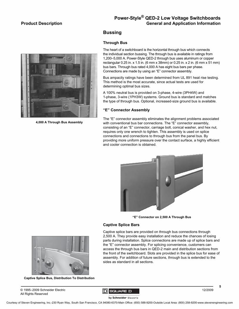
The heart of a switchboard is the horizontal through bus which connects the individual section bussing. The through bus is available in ratings from 1,200–5,000 A. Power-Style QED-2 through bus uses aluminum or copper rectangular 0.25 in. x 1.5 in. (6 mm x 38mm) or 0.25 in. x 2 in. (6 mm x 51 mm) bus bars. Through bus rated 4,000 A has eight bus bars per phase. Connections are made by using an “E” connector assembly.
Bus ampacity ratings have been determined from UL 891 heat rise testing. This method is the most accurate, since actual tests are used for determining optimal bus sizes.
A 100% neutral bus is provided on 3-phase, 4-wire (3PH4W) and 1-phase, 3-wire (1PH3W) systems. Ground bus is standard and matches the type of through bus. Optional, increased-size ground bus is available.
“E” Connector Assembly
The “E” connector assembly eliminates the alignment problems associated with conventional bus bar connections. The “E” connector assembly, consisting of an “E” connector, carriage bolt, conical washer, and hex nut, requires only one wrench to tighten. This assembly is used on splice connections and connections to through bus from the panel bus. By providing more uniform pressure over the contact surface, a highly efficient and cooler connection is obtained.
Captive Splice Bars
Captive splice bars are provided on through bus connections through 2,500 A. They provide easy installation and reduce the chances of losing parts during installation. Splice connections are made up of splice bars and the “E” connector assembly. For splicing convenience, customers can access the through bus bars in QED-2 main and distribution sections from the front of the switchboard. Slots are provided in the splice bus for ease of assembly. For addition of future sections, through bus is extended to the sides as standard in all sections.
4,000 A Through Bus Assembly
“E” Connector on 2,500 A Through Bus
Captive Splice Bus, Distribution To Distribution
Courtesy of Steven Engineering, Inc.-230 Ryan Way, South San Francisco, CA 94080-6370-Main Office: (650) 588-9200-Outside Local Area: (800) 258-9200-www.stevenengineering.com
© 1995–2009 Schneider ElectricAll Rights Reserved
Power-Style® QED-2 Low Voltage SwitchboardsGeneral and Application Information Product Description
612/2009
Main Sections
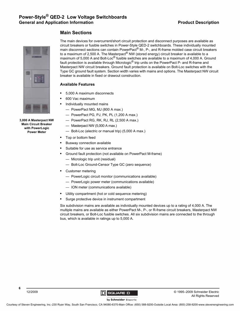
The main devices for overcurrent/short circuit protection and disconnect purposes are available as circuit breakers or fusible switches in Power-Style QED-2 switchboards. These individually mounted main disconnect sections can contain PowerPact® M-, P-, and R-frame molded case circuit breakers to a maximum of 2,500 A. The Masterpact® NW (stored energy) circuit breaker is available to a maximum of 5,000 A and Bolt-Loc® fusible switches are available to a maximum of 4,000 A. Ground fault protection is available through Micrologic® trip units on the PowerPact P- and R-frame and Masterpact NW circuit breakers. Ground fault protection is available on Bolt-Loc switches with the Type GC ground fault system. Section width varies with mains and options. The Masterpact NW circuit breaker is available in fixed or drawout construction.
Available Features
• 5,000 A maximum disconnects
• 600 Vac maximum
• Individually mounted mains
— PowerPact MG, MJ (800 A max.)
— PowerPact PG, PJ, PK, PL (1,200 A max.)
— PowerPact RG, RK, RJ, RL (2,500 A max.)
— Masterpact NW (5,000 A max.)
— Bolt-Loc (electric or manual trip) (5,000 A max.)
• Top or bottom feed
• Busway connection available
• Suitable for use as service entrance
• Ground fault protection (not available on PowerPact M-frame)
— Micrologic trip unit (residual)
— Bolt-Loc Ground-Censor Type GC (zero sequence)
• Customer metering
— PowerLogic circuit monitor (communications available)
— PowerLogic power meter (communications available)
— ION meter (communications available)
• Utility compartment (hot or cold sequence metering)
• Surge protective device in instrument compartment
Six subdivision mains are available as individually mounted devices up to a rating of 4,000 A. The multiple mains are available as either PowerPact M-, P-, or R-frame circuit breakers, Masterpact NW circuit breakers, or Bolt-Loc fusible switches. All six subdivision mains are connected to the through bus, which is available in ratings up to 5,000 A.
3,000 A Masterpact NW Main Circuit Breaker
with PowerLogic Power Meter
Courtesy of Steven Engineering, Inc.-230 Ryan Way, South San Francisco, CA 94080-6370-Main Office: (650) 588-9200-Outside Local Area: (800) 258-9200-www.stevenengineering.com
Power-Style® QED-2 Low Voltage SwitchboardsProduct Description General and Application Information
712/2009© 1995–2009 Schneider Electric
All Rights Reserved
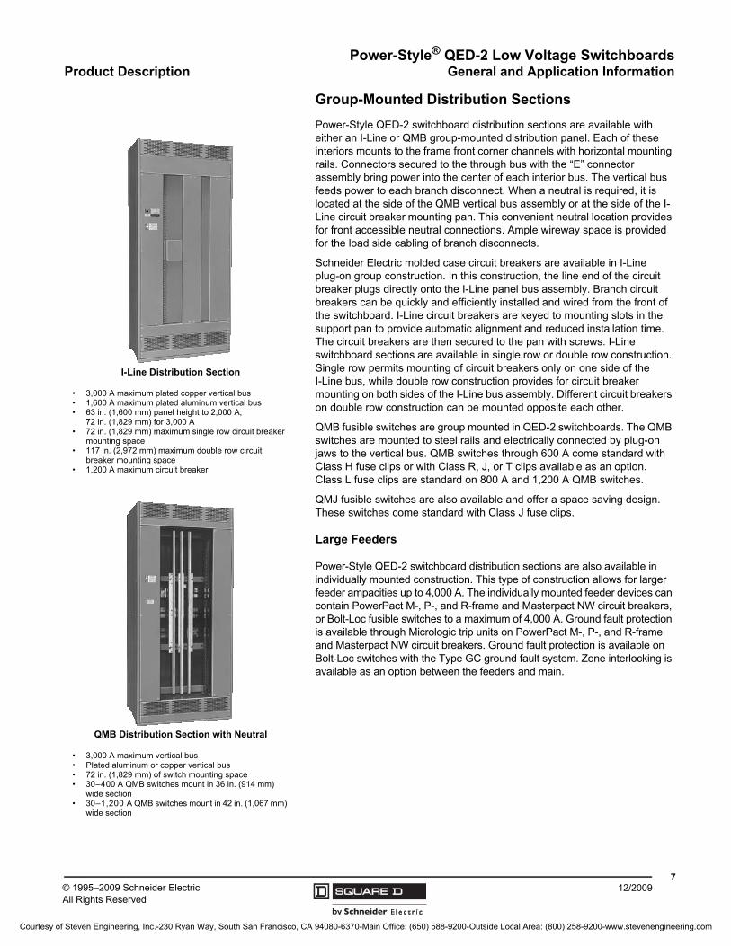
Group-Mounted Distribution Sections
Power-Style QED-2 switchboard distribution sections are available with either an I-Line or QMB group-mounted distribution panel. Each of these interiors mounts to the frame front corner channels with horizontal mounting rails. Connectors secured to the through bus with the “E” connector assembly bring power into the center of each interior bus. The vertical bus feeds power to each branch disconnect. When a neutral is required, it is located at the side of the QMB vertical bus assembly or at the side of the I-Line circuit breaker mounting pan. This convenient neutral location provides for front accessible neutral connections. Ample wireway space is provided for the load side cabling of branch disconnects.
Schneider Electric molded case circuit breakers are available in I-Line plug-on group construction. In this construction, the line end of the circuit breaker plugs directly onto the I-Line panel bus assembly. Branch circuit breakers can be quickly and efficiently installed and wired from the front of the switchboard. I-Line circuit breakers are keyed to mounting slots in the support pan to provide automatic alignment and reduced installation time. The circuit breakers are then secured to the pan with screws. I-Line switchboard sections are available in single row or double row construction. Single row permits mounting of circuit breakers only on one side of the I-Line bus, while double row construction provides for circuit breaker mounting on both sides of the I-Line bus assembly. Different circuit breakers on double row construction can be mounted opposite each other.
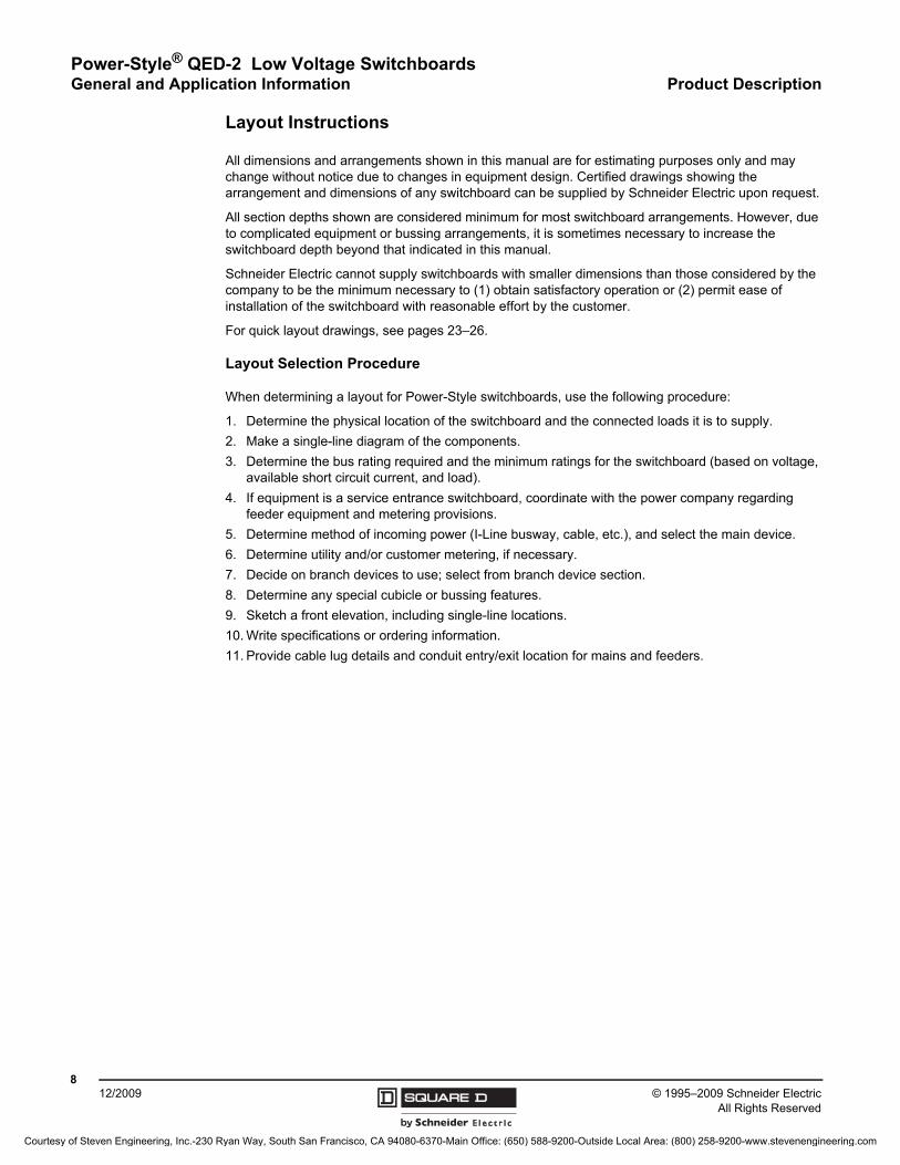
QMB fusible switches are group mounted in QED-2 switchboards. The QMB switches are mounted to steel rails and electrically connected by plug-on jaws to the vertical bus. QMB switches through 600 A come standard with Class H fuse clips or with Class R, J, or T clips available as an option. Class L fuse clips are standard on 800 A and 1,200 A QMB switches.
QMJ fusible switches are also available and offer a space saving design. These switches come standard with Class J fuse clips.
Large Feeders
Power-Style QED-2 switchboard distribution sections are also available in individually mounted construction. This type of construction allows for larger feeder ampacities up to 4,000 A. The individually mounted feeder devices can contain PowerPact M-, P-, and R-frame and Masterpact NW circuit breakers, or Bolt-Loc fusible switches to a maximum of 4,000 A. Ground fault protection is available through Micrologic trip units on PowerPact M-, P-, and R-frame and Masterpact NW circuit breakers. Ground fault protection is available on Bolt-Loc switches with the Type GC ground fault system. Zone interlocking is available as an option between the feeders and main.
• 3,000 A maximum plated copper vertical bus• 1,600 A maximum plated aluminum vertical bus• 63 in. (1,600 mm) panel height to 2,000 A;
72 in. (1,829 mm) for 3,000 A• 72 in. (1,829 mm) maximum single row circuit breaker
mounting space• 117 in. (2,972 mm) maximum double row circuit
breaker mounting space• 1,200 A maximum circuit breaker
I-Line Distribution Section
• 3,000 A maximum vertical bus• Plated aluminum or copper vertical bus• 72 in. (1,829 mm) of switch mounting space• 30–400 A QMB switches mount in 36 in. (914 mm)
wide section• 30–1,200 A QMB switches mount in 42 in. (1,067 mm)
wide section
QMB Distribution Section with Neutral
Courtesy of Steven Engineering, Inc.-230 Ryan Way, South San Francisco, CA 94080-6370-Main Office: (650) 588-9200-Outside Local Area: (800) 258-9200-www.stevenengineering.com
© 1995–2009 Schneider ElectricAll Rights Reserved
Power-Style® QED-2 Low Voltage SwitchboardsGeneral and Application Information Product Description
812/2009
Layout Instructions
All dimensions and arrangements shown in this manual are for estimating purposes only and may change without notice due to changes in equipment design. Certified drawings showing the arrangement and dimensions of any switchboard can be supplied by Schneider Electric upon request.
All section depths shown are considered minimum for most switchboard arrangements. However, due to complicated equipment or bussing arrangements, it is sometimes necessary to increase the switchboard depth beyond that indicated in this manual.
Schneider Electric cannot supply switchboards with smaller dimensions than those considered by the company to be the minimum necessary to (1) obtain satisfactory operation or (2) permit ease of installation of the switchboard with reasonable effort by the customer.
For quick layout drawings, see pages 23–26.
Layout Selection Procedure
When determining a layout for Power-Style switchboards, use the following procedure:
1. Determine the physical location of the switchboard and the connected loads it is to supply.
2. Make a single-line diagram of the components.
3. Determine the bus rating required and the minimum ratings for the switchboard (based on voltage, available short circuit current, and load).
4. If equipment is a service entrance switchboard, coordinate with the power company regarding feeder equipment and metering provisions.
5. Determine method of incoming power (I-Line busway, cable, etc.), and select the main device.
6. Determine utility and/or customer metering, if necessary.
7. Decide on branch devices to use; select from branch device section.
8. Determine any special cubicle or bussing features.
9. Sketch a front elevation, including single-line locations.
10. Write specifications or ordering information.
11. Provide cable lug details and conduit entry/exit location for mains and feeders.
Courtesy of Steven Engineering, Inc.-230 Ryan Way, South San Francisco, CA 94080-6370-Main Office: (650) 588-9200-Outside Local Area: (800) 258-9200-www.stevenengineering.com
Power-Style® QED-2 Low Voltage SwitchboardsIncoming Connections / Structure Modifications General and Application Information
912/2009© 1995–2009 Schneider Electric
All Rights Reserved
Incoming Connections
Line-side lug connections are available for single main devices, bussed auxiliary sections, utility compartments, I-Line distribution sections, and quick connect generator switchboards. Lugs or studs can be provided as required.
Transformer connections are available for Power-Dry II™, Power-Cast II™, Uni-Cast II™, and liquid-filled transformers. These connections require a switchboard depth of 54 or 60 in. (1,372 or 1,524 mm). For more information on dimensions and equipment alignment, see catalog # 6020CT9401, Power-Zone® Load Center Unit Substations.
Busway connections are available with a flanged collar (Qwik Flange™) or flanged end. Qwik Flange is available for NEMA Type 1, top feed only. They are available for aluminum bus from 800–4,000 A and for copper bus from 800–5,000 A. For more details on busway, see catalog # 5600CT9101, Busway Systems.
Connect to existing—To add a section to an existing switchboard, the following is required:
• Factory order number from the nameplate of the existing switchboard
• Location of the through bus for the adjacent section: top, middle, or bottom
• Bus bar size if 2,000 A or smaller: 1.5 or 2.0 in. (38 or 51 mm)
• Depth of through bus from the front of the switchboard: 19.5, 27.5, or 36.0 in. (495, 699, or 914 mm)
Special connections are available for Model 6 motor control centers. Contact your local Schneider Electric representative for more information.
Structure Modifications
• Auxiliary section—bussed or unbussed
• Barriers between sections (steel or non-conductive)
• Bottom closure plate
• Corner sections (≤ 2,500 A), loadside wireway section and rear wireway (for LTM only)
• Corrosion resistant base channels (standard for NEMA Type 3R)
• Drip hood (NEMA Type 1; not available for NEMA Type 3R)
• Hinged rear doors (must have rear access)
• Increased depth and width (for increased wire bending space)
• Interior lights and GFI receptacle for NEMA Type 3R enclosure
• Mimic nameplate (anodized aluminum or plastic)
• Paint—ANSI 49 (standard), ANSI 61, or special (contact your local Schneider Electric representative)
• Pullbox (NEMA Type 1 enclosure only)
• Reduced height sections—76.5 in. (requires longer lead time)
• Rodent barrier (standard on NEMA Type 3R)
• SIS control wire
• Strip heater and thermostat
• Surge arrestor
For additional options, please contact your local Schneider Electric representative.
Auxiliary Section information
Ampacity (A) Width Depth
800–2,000 24 in. (610 mm)24 in. (610 mm)
2,500 30 in. (762 mm)
3,000 36 in. (914 mm) 36 in. (914 mm)
4,000 42 in. (1,067 mm)48 in. (1,219 mm)
5,000 48 in. (1,219 mm)
NOTE: Requires an auxiliary section.
Fire Pump Lugs
Options
• #10-2/0 per phase and neutral
• #6-350 kcmil per phase and neutral
Courtesy of Steven Engineering, Inc.-230 Ryan Way, South San Francisco, CA 94080-6370-Main Office: (650) 588-9200-Outside Local Area: (800) 258-9200-www.stevenengineering.com
Power-Style® QED-2 Low Voltage SwitchboardsGeneral and Application Information Customer Metering
© 1995–2009 Schneider ElectricAll Rights Reserved
1012/2009
Customer Metering
PowerLogic® Power Monitoring and Control
NOTE: Please refer to www.powerlogic.com for a complete and up-to-date list of feature availability. Some features are optional.
For available configurations/placement options for power meters, circuit monitors, and ION meters, see page 12. For additional clarification, contact your local Schneider Electric representative.
Power Meter
Class Type Description
3020PM-820 Power meter module with display 0.25% accuracy with logging, alarms, I/O modules
PM-850 Same as PM-820 plus trending/forecasting, steady state waveform capture
PM-870 Same as PM-850 plus disturbance waveform capture, sag/swell metering
Circuit Monitors
Class Type Description
3020
CMDLC Liquid crystal display used for both circuit monitors
CMDVF Upgrade to vacuum fluorescent display with infrared port
CM4250 Multi-function, digital instrumentation, data acquisition, control device, cycle-by-cycle event recording
CM4000T Same as CM4250 plus transient voltage monitoring, flicker IEC 61000-4-15
ION 7550/7650 Meters
Catalog No. Description
S7550A0C0B6A0A0A Basic unit: Integrated display, instrumentation, power quality, waveform capture, one RS232/RS485 port, one RS-485 jack, one Type 2 optical port, eight digital inputs, four digital outputs, and three onboard relays
S7550A0C0B6E0A0A Basic unit plus EthernetS7650A0C0B6A0A0A Basic unit plus additional ION7650 featuresS7650A0C0B6E0A0A Basic unit plus Ethernet and additional ION7650 featuresS7650A0C0B6C1A0A Basic unit plus Ethernet, internal modem, and additional ION7650 features
S7650B1C0B6C1A0A Basic unit plus Ethernet, 1,024 samples/cycle instead of 512, 10 MB of logging instead of 5 MB, internal modem, and additional ION7650 features
Input/Output Modules
Class Type Description
3020
IOC44 I/O card with 4 status in, 3 relay out, and 1 KYZ out
IOX2411 I/O extender module with 4 DC status inputs, 2 DC digital outputs, and 1 analog output
IOX0404 I/O extender module with 4 status inputs and 4 analog inputs
IOX08 I/O extender module with 8 status inputs (120 Vac)
IOX I/O extender module only, no installed I/O
PM8-ECC Ethernet communications card with HTML capabilities for PM8 family
ECC21 Ethernet communications card with HTML capabilities, for CM3/4 family
Not applicable
PM8M2222 2 digital outputs, 2 digital inputs, 2 analog outputs, and 2 analog inputs
PM8M26 2 digital outputs and 6 digital inputs
PM822 2 digital outputs and 2 digital inputs
Instrument Transformer Requirements 1
1 Drawout circuit breakers require three CTs for all voltages.
Device1PH3W
120/240 V3PH3WDelta
3PH4W
WyeDelta
208Y/120 480Y/277 600Y/347
Circuit monitor 2 CTs 2 CTs, 1 CPT 2
2 CPT is not required for 240 V Delta.
3 CTs 3 CTs 3 CTs, 1 CPT 3 CTs
Power meter 2 CTs 2 CTs, 1 CPT 2 3 CTs 3 CTs 3 CTs 3 CTs
Ion meter 3
3 PTs are necessary only when Canadian Standards Association (CSA) certification is required.
2 CTs, 2 PTs 2 CTs, 1 CPT 2, 3 PTs 3 CTs 3 CTs, 1 CPT, 3 PTs 3 CTs, 1 CPT, 3 PTs 3 CTs, 1 CPT, 3 PTs
Courtesy of Steven Engineering, Inc.-230 Ryan Way, South San Francisco, CA 94080-6370-Main Office: (650) 588-9200-Outside Local Area: (800) 258-9200-www.stevenengineering.com
Power-Style® QED-2 Low Voltage SwitchboardsCustomer Metering General and Application Information
1112/2009© 1995–2009 Schneider Electric
All Rights Reserved
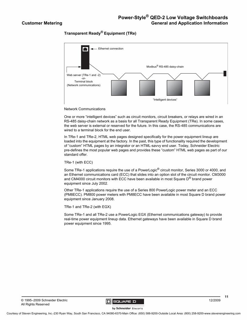
Transparent Ready® Equipment (TRe)
Network Communications
One or more “intelligent devices” such as circuit monitors, circuit breakers, or relays are wired in an RS-485 daisy-chain network as a basis for all Transparent Ready Equipment (TRe). In some cases, the web server is external or reserved for the future. In this case, the RS-485 communications are wired to a terminal block for the end user.
In TRe-1 and TRe-2, HTML web pages designed specifically for the power equipment lineup are loaded into the equipment at the factory. In the past, this type of functionality required the development of “custom” HTML pages by an integrator or an HTML-savvy end user. Today, Schneider Electric pre-defines the most popular web pages and provides these “custom” HTML web pages as part of our standard offer.
TRe-1 (with ECC)
Some TRe-1 applications require the use of a PowerLogic® circuit monitor, Series 3000 or 4000, and an Ethernet communications card (ECC) that slides into an option slot of the circuit monitor. CM3000 and CM4000 circuit monitors with ECC have been available in most Square D® brand power equipment since July 2002.
Other TRe-1 applications require the use of a Series 800 PowerLogic power meter and an ECC (PM8ECC). PM800 power meters with PM8ECC have been available in most Square D brand power equipment since January 2008.
TRe-1 and TRe-2 (with EGX)
Some TRe-1 and all TRe-2 use a PowerLogic EGX (Ethernet communications gateway) to provide real-time power equipment lineup data. Ethernet gateways have been available in Square D brand power equipment since 1995.
Ethernet connection
Web server (TRe-1 and -2)-or-
Terminal block(Network communications)
“Intelligent devices“
Modbus® RS-485 daisy-chain
Courtesy of Steven Engineering, Inc.-230 Ryan Way, South San Francisco, CA 94080-6370-Main Office: (650) 588-9200-Outside Local Area: (800) 258-9200-www.stevenengineering.com
Power-Style® QED-2 Low Voltage SwitchboardsGeneral and Application Information Customer Metering
© 1995–2009 Schneider ElectricAll Rights Reserved
1212/2009
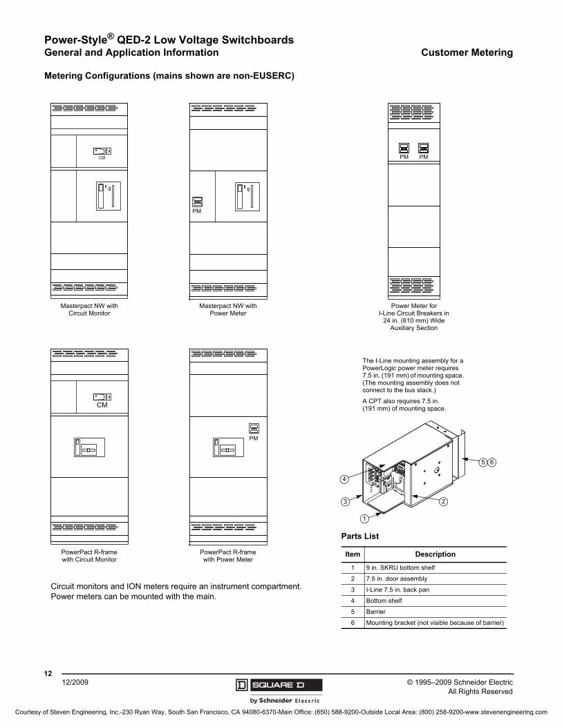
Metering Configurations (mains shown are non-EUSERC)
CM
PM
CM
PM
PMPM
Masterpact NW with Circuit Monitor
Masterpact NW with Power Meter
PowerPact R-frame with Circuit Monitor
PowerPact R-frame with Power Meter
Power Meter for I-Line Circuit Breakers in
24 in. (610 mm) Wide Auxiliary Section
Parts List
Item Description
1 9 in. SKRU bottom shelf
2 7.5 in. door assembly
3 I-Line 7.5 in. back pan
4 Bottom shelf
5 Barrier
6 Mounting bracket (not visible because of barrier)
5
4
3 2
1
6
Circuit monitors and ION meters require an instrument compartment. Power meters can be mounted with the main.
The I-Line mounting assembly for a PowerLogic power meter requires 7.5 in. (191 mm) of mounting space. (The mounting assembly does not connect to the bus stack.)
A CPT also requires 7.5 in. (191 mm) of mounting space.
Courtesy of Steven Engineering, Inc.-230 Ryan Way, South San Francisco, CA 94080-6370-Main Office: (650) 588-9200-Outside Local Area: (800) 258-9200-www.stevenengineering.com
Power-Style® QED-2 Low Voltage SwitchboardsElectronic Trip Systems General and Application Information
1312/2009© 1995–2009 Schneider Electric
All Rights Reserved
Electronic Trip Systems
M-frame circuit breakers are available with the ET 1.0 electronic trip system. P-frame and R-frame circuit breakers are available with either the ET1.0I basic electronic trip system or the Micrologic electronic trip system. The Masterpact NW (stored energy) circuit breakers are available with the Micrologic electronic trip system. The sensing system responds to the flow of current through the circuit breaker.
Thermal Imaging
The thermal imaging function protects the cables or bus bars from overheating in case of low amplitude repetitive faults. Such overheating can be due to repetitive motor starting, fluctuating load, intermittent ground faults, or subsequent closing after a fault. Traditional electronic protection does not protect against repetitive faults because the duration of each overload above the pickup setting is too short to achieve effective tripping. Nevertheless, each overload involves a temperature rise in the installation, the cumulative effect of which could lead to overheating of the system.
The thermal imaging function remembers and integrates the thermal heating caused by each pickup setting overrun. Before tripping, the integrated heating value reduces the associated time delay and, therefore, the reaction of the trip unit is closer to the real heating of the power network system. After tripping, the function will also reduce the time delay when closing the circuit breaker on an overload.
True RMS Current Sensing
The sensing system responds to the flow of current through the circuit breaker. The trip unit samples the current waveform to provide true RMS protection through the 15th harmonic. This true RMS sensing gives accurate values for the magnitude of a non-sinusoidal waveform. Therefore, the heating effects of harmonically distorted waveforms are accurately evaluated.
The Micrologic H trip unit provides additional sampling of the waveforms to measure and provide waveform capture of harmonic distortion to the 31st harmonic.
ET Trip System
ET trip units are available with M-, P-, and R-frame UL/IEC circuit breakers. The trip units are not field-interchangeable and do not accept any communications or other trip unit accessories. The trip system uses a set of current transformers (called CTs or sensors) to sense current, a trip unit to evaluate the current, and a tripping solenoid to trip the circuit breaker.
ET1.0 (M-Frame only)
The ET1.0 trip system is available on M-frame circuit breakers and is equipped with fixed long-time and adjustable instantaneous (LI) tripping functions only. The long-time pickup is 1.0 x sensor rating (In), while the instantaneous pickup is adjustable (dial settings from 2–10 x In) with no intentional time delay.
ET1.0I (P-Frame and R-Frame only)
The ET1.0I trip system is available on both P-frame and R-frame circuit breakers and is equipped with fixed long-time and adjustable instantaneous (LI) tripping functions only. The long-time pickup is 1.0 x sensor rating (In), while the instantaneous pickup is adjustable (dial settings from 1.5–12 x In) with no intentional time delay.
ET1.0M (P-Frame only)
The ET1.0M trip system is only available on P-frame motor circuit protectors and provides protection for short circuit conditions only. The trip unit has a single adjustment for instantaneous pickup that, if exceeded, trips the circuit breaker with no intentional delay. Instantaneous trip dial settings are 2–16 x In for 600 A circuit breakers and 1.5–12 x In for 800–1,200 A circuit breakers.
Courtesy of Steven Engineering, Inc.-230 Ryan Way, South San Francisco, CA 94080-6370-Main Office: (650) 588-9200-Outside Local Area: (800) 258-9200-www.stevenengineering.com
© 1995–2009 Schneider ElectricAll Rights Reserved
Power-Style® QED-2 Low Voltage SwitchboardsGeneral and Application Information Electronic Trip Systems
1412/2009
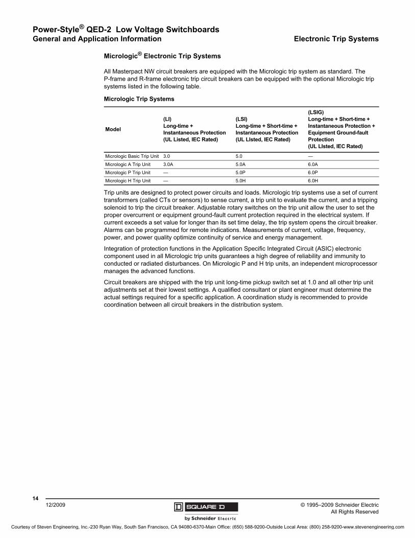
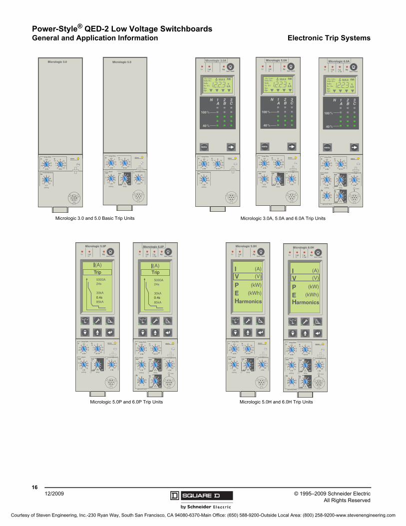
Micrologic® Electronic Trip Systems
All Masterpact NW circuit breakers are equipped with the Micrologic trip system as standard. The P-frame and R-frame electronic trip circuit breakers can be equipped with the optional Micrologic trip systems listed in the following table.
Trip units are designed to protect power circuits and loads. Micrologic trip systems use a set of current transformers (called CTs or sensors) to sense current, a trip unit to evaluate the current, and a tripping solenoid to trip the circuit breaker. Adjustable rotary switches on the trip unit allow the user to set the proper overcurrent or equipment ground-fault current protection required in the electrical system. If current exceeds a set value for longer than its set time delay, the trip system opens the circuit breaker. Alarms can be programmed for remote indications. Measurements of current, voltage, frequency, power, and power quality optimize continuity of service and energy management.
Integration of protection functions in the Application Specific Integrated Circuit (ASIC) electronic component used in all Micrologic trip units guarantees a high degree of reliability and immunity to conducted or radiated disturbances. On Micrologic P and H trip units, an independent microprocessor manages the advanced functions.
Circuit breakers are shipped with the trip unit long-time pickup switch set at 1.0 and all other trip unit adjustments set at their lowest settings. A qualified consultant or plant engineer must determine the actual settings required for a specific application. A coordination study is recommended to provide coordination between all circuit breakers in the distribution system.
Micrologic Trip Systems
Model
(LI)Long-time + Instantaneous Protection(UL Listed, IEC Rated)
(LSI)Long-time + Short-time + Instantaneous Protection(UL LIsted, IEC Rated)
(LSIG)Long-time + Short-time + Instantaneous Protection + Equipment Ground-fault Protection (UL LIsted, IEC Rated)
Micrologic Basic Trip Unit 3.0 5.0 —
Micrologic A Trip Unit 3.0A 5.0A 6.0A
Micrologic P Trip Unit — 5.0P 6.0P
Micrologic H Trip Unit — 5.0H 6.0H
Courtesy of Steven Engineering, Inc.-230 Ryan Way, South San Francisco, CA 94080-6370-Main Office: (650) 588-9200-Outside Local Area: (800) 258-9200-www.stevenengineering.com

Power-Style® QED-2 Low Voltage SwitchboardsElectronic Trip Systems General and Application Information
1512/2009© 1995–2009 Schneider Electric
All Rights Reserved
Micrologic Trip Unit Features
Feature
Micrologic Trip Unit (X = Standard Feature O = Available Option)
Standard Ammeter Power Harmonics
3.0 5.0 2.0A 3.0A 5.0A 6.0A 5.0P 6.0P 5.0H 6.0H
Field-Installable X X X X X X X X X XLI X XLS0 XLSI X X X XLSIG/Ground-Fault Trip1
1 Requires neutral current transformer on 3-phase, 4-wire circuits.
X X XGround-Fault Alarm/No Trip1, 2
2 Requires M6C Programmable Contact Module.
X XGround-Fault Alarm and Trip1, 2 X XAdjustable Rating Plugs X X X X X X X X X XTrue RMS Sensing X X X X X X X X X XUL Listed X X X X X X X X XThermal Imaging X X X X X X X X X XPhase-Loading Bar Graph X X X X X X X XLED for Long-Time Pick-Up X X X X X X X X X XLED for Trip Indication X X X X X X X XDigital Ammeter X X X X X X X XZone-Selective Interlocking 3
3 Not available for 2.0A trip unit as upstream devices.
X X X X X X XCommunications O O O O X X X XLCD Dot Matrix Display X X X XAdvanced User Interface X X X XProtective Relay Functions X X X XNeutral Protection1 X X X XContact Wear Indication X X X XIncremental Fine Tuning of Settings X X X XSelectable Long-Time Delay Bands X X X XPower Measurement X X X XPower Quality Measurements X XWaveform Capture X X
Rating Plugs for Micrologic 3.0, 5.0, 6.0, 7.0 A/P/H Trip Units
Standard OptionSettings
(Tolerance 1.05-1.2)
UL/ANSI
Plug A 0.40 - 0.45 - 0.50 - 0.60 - 0.63 - 0.70 - 0.80 - 0.90 - 1.0
Plug B 0.40 - 0.44 - 0.50 - 0.56 - 0.63 - 0.75 - 0.88 - 0.95 - 1.0
Plug C 0.42 - 0.50 - 0.53 - 0.58 - 0.67 - 0.75 - 0.83 - 0.95 - 1.0
Plug D 0.40 - 0.48 - 0.64 - 0.70 - 0.80 - 0.90 - 0.93 - 0.95 - 1.0
Plug E 0.60 - 0.70 - 0.75 - 0.80 - 0.85 - 0.90 - 0.93 - 0.95 - 1.0
Plug F 0.84 - 0.86 - 0.88 - 0.90 - 0.92 - 0.94 - 0.96 - 0.98 - 1.0
Plug G 0.66 - 0.68 - 0.7 0- 0.72 - 0.74 - 0.76 - 0.78 - 0.80 - 0.82
Plug H 0.48 - 0.50 - 0.52 - 0.54 - 0.56 - 0.58 - 0.60 - 0.62 - 0.64
Courtesy of Steven Engineering, Inc.-230 Ryan Way, South San Francisco, CA 94080-6370-Main Office: (650) 588-9200-Outside Local Area: (800) 258-9200-www.stevenengineering.com
Power-Style® QED-2 Low Voltage SwitchboardsGeneral and Application Information Electronic Trip Systems
© 1995–2009 Schneider ElectricAll Rights Reserved
1612/2009
Micrologic 3.0
.4.45.5
.6.63
.7.8.9
1
x Ir
23
4 5 6810
121.5
setting
Im
.512
48
121620
instantaneous
long timealarmIr tr
(s)
x In @ 6 Ir24
Micrologic 5.0
.4.45.5
.6.63
.7.8.9
1
delay
short I itsd
(s)
on I2t
.2
.3.4 .4
.1
.2.3
.10off
instantaneous
long timealarmIr
x In .512
48
121620
tr(s)
@ 6 Ir24
setting
x Ir
22.5
34 5
68
10
Isd
1.5x In
3
46 8 10
12
15off2
Micrologic 3.0A
40
100%
%
menu
.4.45.5
.6.63
.7.8.9
1
long timealarmIr
x In .512
48
121620
tr(s)
@ 6 Ir24
x Ir
23
4 5 6810
101.5
setting
Iminstantaneous
kAs
Ir=Ii=
tr=Isd=
Ig=
tsd=Δt=
tg=
IΔn= MAX
Micrologic 5.0A
40
100%
%
menu
.4.45.5
.6.63
.7.8.9
1
delay
short I itsd
(s)
on I2t
.
.. .
.
..
.0off
instantaneous
long timealarmIr
x In .512
48
121620
tr(s)
@ 6 Ir24
settingx Ir
22.5
34 5
68
10
Isd
1.5x In
22.5
34 5
68
101.5
kAs
Ir=Ii=
tr=Isd=
Ig=
tsd=Δt=
tg=
IΔn= MAX
Micrologic 6.0A
40
100%
%
menu
.4.45.5
.6.63
.7.8.9
1
delay
short I itsd
(s)
on I2t
.2
.3.4 .4
.1
.2.3
.10off
instantaneous
long timealarmIr
x In
ground fault
BC
DE F
GH
J
Ig tg (s)
on I2t
.2
.3.4 .4
.1
.2.3
.10off
A
.512
48
121620
tr(s)
@ 6 Ir24
setting
x Ir
22.5
34 5
68
10
Isd
1.5x In
43
6 8 101215
off2
test
kAs
Ir=Ii=
tr=Isd=
Ig=
tsd=Δt=
tg=
IΔn= MAX
Micrologic 3.0A, 5.0A and 6.0A Trip UnitsMicrologic 3.0 and 5.0 Basic Trip Units
Micrologic 6.0P
.4.45.5
.6.63
.7.8.9
1
delay
short tsd (s)
on I2t
.2
.3.4 .4
.1
.2.3
.10off
instantaneous
long timealarmIr
x In
ground fault
BC
DE
GH
J
Ig tg (s)
on I2t
.2
.3.4 .4
.1
.2.3
.10off
A
setting
x Ir
22.5
34 5
68
10
Isd
1.5
.512
48
121620
tr(s)
@ 6 Ir24
test
85kA
30kA
24s5000A
I(A)Trip
0.4s
I i
x In2
410
3
6 8
1215
off
Micrologic 5.0H
delaysettingx Ir
22.5
34 5
68
10
Isd
1.5
.4.45.5
.6.63
.7.8.9
1
short tsd (s)
on I2t
.2
.3.4 .4
.1
.2.3
.10off
instantaneous
long timealarmIr
x In .512
48
121620
tr(s)
@ 6 Ir24
I (A)
V (V)
P (kW)
E (kWh)
Harmonics
I i
x In2
410
3
6 8
1215
off
Micrologic 6.0H
.4.45.5
.6.63
.7.8.9
1
delay
short tsd (s)
on I2t
.2
.3.4 .4
.1
.2.3
.10off
instantaneous
long timealarmIr
x In
ground fault
BC
DE
GH
J
Ig tg (s)
on I2t
.2
.3.4 .4
.1
.2.3
.10off
A
setting
x Ir
22.5
34 5
68
10
Isd
1.5
.512
48
121620
tr(s)
@ 6 Ir24
test
I (A)
V (V)
P (kW)
E (kWh)
Harmonics
I i
x In2
410
3
6 8
1215
off
Micrologic 5.0P
delaysettingx Ir
22.5
34 5
68
10
Isd
1.5
.4.45.5
.6.63
.7.8.9
1
short tsd (s)
on I2t
.
.. .
.
..
.0off
instantaneous
long timealarmIr
x In .512
48
121620
tr(s)
@ 6 Ir24
85kA
30kA
24s5000A
I(A)Trip
0.4s
I i
x In2
410
3
6 8
1215
off
Micrologic 5.0H and 6.0H Trip UnitsMicrologic 5.0P and 6.0P Trip Units
Courtesy of Steven Engineering, Inc.-230 Ryan Way, South San Francisco, CA 94080-6370-Main Office: (650) 588-9200-Outside Local Area: (800) 258-9200-www.stevenengineering.com
Power-Style® QED-2 Low Voltage SwitchboardsIndividually Mounted Circuit Breakers General and Application Information
1712/2009© 1995–2009 Schneider Electric
All Rights Reserved
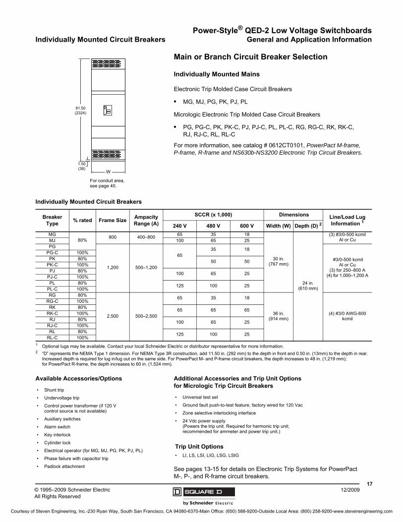
Main or Branch Circuit Breaker Selection
Individually Mounted Mains
Electronic Trip Molded Case Circuit Breakers
• MG, MJ, PG, PK, PJ, PL
Micrologic Electronic Trip Molded Case Circuit Breakers
• PG, PG-C, PK, PK-C, PJ, PJ-C, PL, PL-C, RG, RG-C, RK, RK-C, RJ, RJ-C, RL, RL-C
For more information, see catalog # 0612CT0101, PowerPact M-frame, P-frame, R-frame and NS630b-NS3200 Electronic Trip Circuit Breakers.
See pages 13-15 for details on Electronic Trip Systems for PowerPact M-, P-, and R-frame circuit breakers.
W
91.50(2324)
1.50(38)
For conduit area, see page 40.
Individually Mounted Circuit Breakers
Breaker Type
% rated Frame SizeAmpacity Range (A)
SCCR (x 1,000) Dimensions Line/Load Lug Information 1
1 Optional lugs may be available. Contact your local Schneider Electric or distributor representative for more information.
240 V 480 V 600 V Width (W) Depth (D) 2
2 “D” represents the NEMA Type 1 dimension. For NEMA Type 3R construction, add 11.50 in. (292 mm) to the depth in front and 0.50 in. (13mm) to the depth in rear. Increased depth is required for lug in/lug out on the same side. For PowerPact M- and P-frame circuit breakers, the depth increases to 48 in. (1,219 mm);for PowerPact R-frame, the depth increases to 60 in. (1,524 mm).
MG80%
800 400–80065 35 18
30 in.(767 mm)
24 in. (610 mm)
(3) #3/0-500 kcmil Al or CuMJ 100 65 25
PG
1,200 500–1,200
6535 18
#3/0-500 kcmil Al or Cu
(3) for 250–800 A(4) for 1,000–1,200 A
PG-C 100%PK 80%
50 50PK-C 100%
PJ 80%100 65 25
PJ-C 100%PL 80%
125 100 25PL-C 100%RG 80%
2,500 500–2,500
65 35 18
36 in.(914 mm)
(4) #3/0 AWG-600 kcmil
RG-C 100%RK 80%
65 65 65RK-C 100%
RJ 80%100 65 25
RJ-C 100%RL 80%
125 100 25RL-C 100%
Available Accessories/Options
• Shunt trip
• Undervoltage trip
• Control power transformer (if 120 V control source is not available)
• Auxiliary switches
• Alarm switch
• Key interlock
• Cylinder lock
• Electrical operator (for MG, MJ, PG, PK, PJ, PL)
• Phase failure with capacitor trip
• Padlock attachment
Additional Accessories and Trip Unit Options for Micrologic Trip Circuit Breakers
• Universal test set
• Ground fault push-to-test feature, factory wired for 120 Vac
• Zone selective interlocking interface
• 24 Vdc power supply(Powers the trip unit. Required for harmonic trip unit; recommended for ammeter and power trip unit.)
Trip Unit Options
• LI, LS, LSI, LIG, LSG, LSIG
Courtesy of Steven Engineering, Inc.-230 Ryan Way, South San Francisco, CA 94080-6370-Main Office: (650) 588-9200-Outside Local Area: (800) 258-9200-www.stevenengineering.com
Power-Style® QED-2 Low Voltage SwitchboardsGeneral and Application Information Individually Mounted Circuit Breakers
© 1995–2009 Schneider ElectricAll Rights Reserved
1812/2009
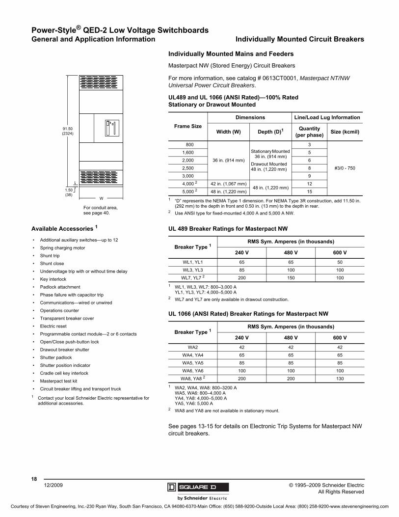
Individually Mounted Mains and Feeders
Masterpact NW (Stored Energy) Circuit Breakers
For more information, see catalog # 0613CT0001, Masterpact NT/NW Universal Power Circuit Breakers.
See pages 13-15 for details on Electronic Trip Systems for Masterpact NW circuit breakers.
W
91.50(2324)
1.50(38)
For conduit area, see page 40.
UL489 and UL 1066 (ANSI Rated)—100% RatedStationary or Drawout Mounted
Frame Size
Dimensions Line/Load Lug Information
Width (W) Depth (D)1
1 “D” represents the NEMA Type 1 dimension. For NEMA Type 3R construction, add 11.50 in. (292 mm) to the depth in front and 0.50 in. (13 mm) to the depth in rear.
Quantity(per phase)
Size (kcmil)
800
36 in. (914 mm)
Stationary Mounted 36 in. (914 mm)
Drawout Mounted 48 in. (1,220 mm)
3
#3/0 - 750
1,600 5
2,000 6
2,500 8
3,000 9
4,000 2
2 Use ANSI type for fixed-mounted 4,000 A and 5,000 A NW.
42 in. (1,067 mm)48 in. (1,220 mm)
12
5,000 2 48 in. (1,220 mm) 15
Available Accessories 1
1 Contact your local Schneider Electric representative for additional accessories.
• Additional auxiliary switches—up to 12
• Spring charging motor
• Shunt trip
• Shunt close
• Undervoltage trip with or without time delay
• Key interlock
• Padlock attachment
• Phase failure with capacitor trip
• Communications—wired or unwired
• Operations counter
• Transparent breaker cover
• Electric reset
• Programmable contact module—2 or 6 contacts
• Open/Close push-button lock
• Drawout breaker shutter
• Shutter padlock
• Shutter position indicator
• Cradle cell key interlock
• Masterpact test kit
• Circuit breaker lifting and transport truck
UL 489 Breaker Ratings for Masterpact NW
Breaker Type 1
1 WL1, WL3, WL7: 800–3,000 AYL1, YL3, YL7: 4,000–5,000 A
RMS Sym. Amperes (in thousands)
240 V 480 V 600 V
WL1, YL1 65 65 50
WL3, YL3 85 100 100
WL7, YL7 2
2 WL7 and YL7 are only available in drawout construction.
200 150 100
UL 1066 (ANSI Rated) Breaker Ratings for Masterpact NW
Breaker Type 1
1 WA2, WA4, WA8: 800–3200 AWA5, WA6: 800–4,000 AYA4, YA8: 4,000–5,000 AYA5, YA6: 5,000 A
RMS Sym. Amperes (in thousands)
240 V 480 V 600 V
WA2 42 42 42
WA4, YA4 65 65 65
WA5, YA5 85 85 85
WA6, YA6 100 100 100
WA8, YA8 2
2 WA8 and YA8 are not available in stationary mount.
200 200 130
Courtesy of Steven Engineering, Inc.-230 Ryan Way, South San Francisco, CA 94080-6370-Main Office: (650) 588-9200-Outside Local Area: (800) 258-9200-www.stevenengineering.com
Power-Style® QED-2 Low Voltage SwitchboardsIndividually Mounted Circuit Breakers General and Application Information
1912/2009© 1995–2009 Schneider Electric
All Rights Reserved
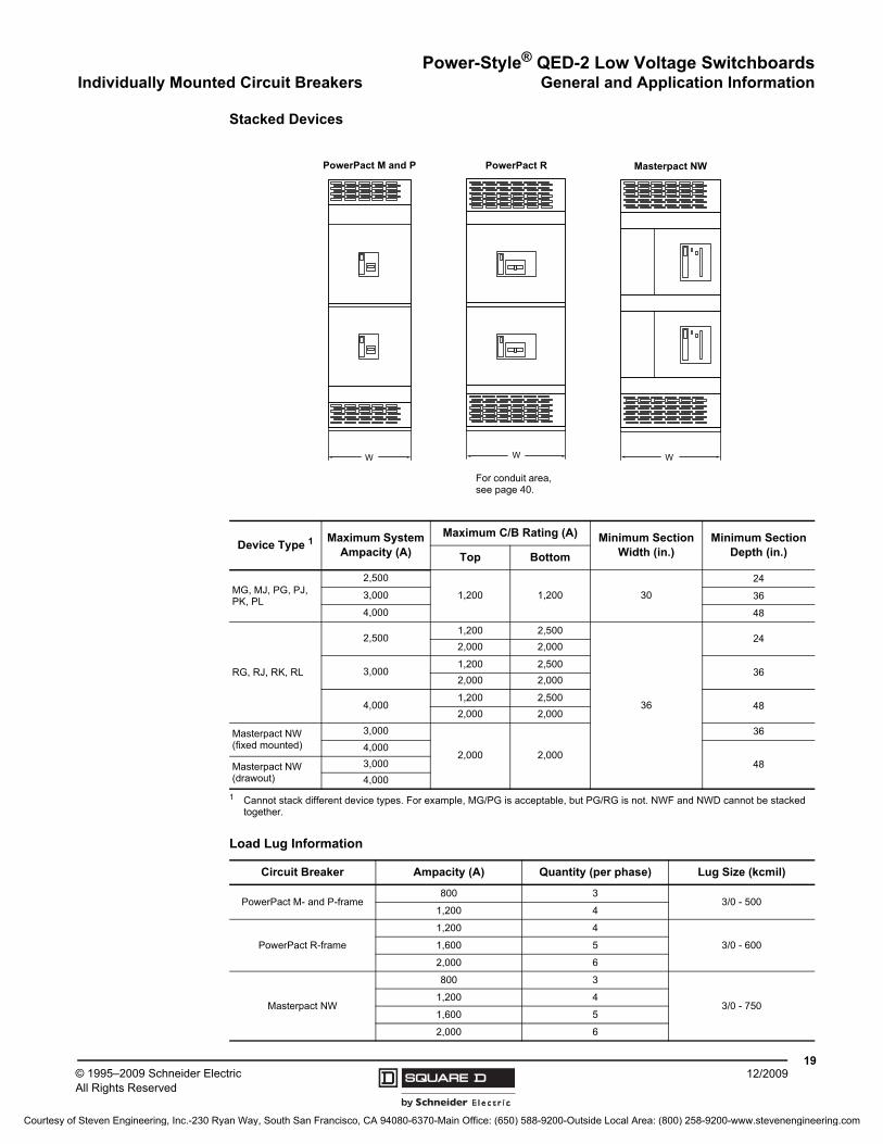
Stacked Devices
Device Type 1
1 Cannot stack different device types. For example, MG/PG is acceptable, but PG/RG is not. NWF and NWD cannot be stacked together.
Maximum System Ampacity (A)
Maximum C/B Rating (A) Minimum Section Width (in.)
Minimum Section Depth (in.)Top Bottom
MG, MJ, PG, PJ, PK, PL
2,500
1,200 1,200 30
24
3,000 36
4,000 48
RG, RJ, RK, RL
2,5001,200 2,500
36
242,000 2,000
3,0001,200 2,500
362,000 2,000
4,0001,200 2,500
482,000 2,000
Masterpact NW (fixed mounted)
3,000
2,000 2,000
36
4,000
48Masterpact NW (drawout)
3,000
4,000
Load Lug Information
Circuit Breaker Ampacity (A) Quantity (per phase) Lug Size (kcmil)
PowerPact M- and P-frame800 3
3/0 - 5001,200 4
PowerPact R-frame
1,200 4
3/0 - 6001,600 5
2,000 6
Masterpact NW
800 3
3/0 - 7501,200 4
1,600 5
2,000 6
W W W
Masterpact NWPowerPact RPowerPact M and P
For conduit area, see page 40.
Courtesy of Steven Engineering, Inc.-230 Ryan Way, South San Francisco, CA 94080-6370-Main Office: (650) 588-9200-Outside Local Area: (800) 258-9200-www.stevenengineering.com
Power-Style® QED-2 Low Voltage SwitchboardsGeneral and Application Information Individually Mounted Circuit Breakers
© 1995–2009 Schneider ElectricAll Rights Reserved
2012/2009
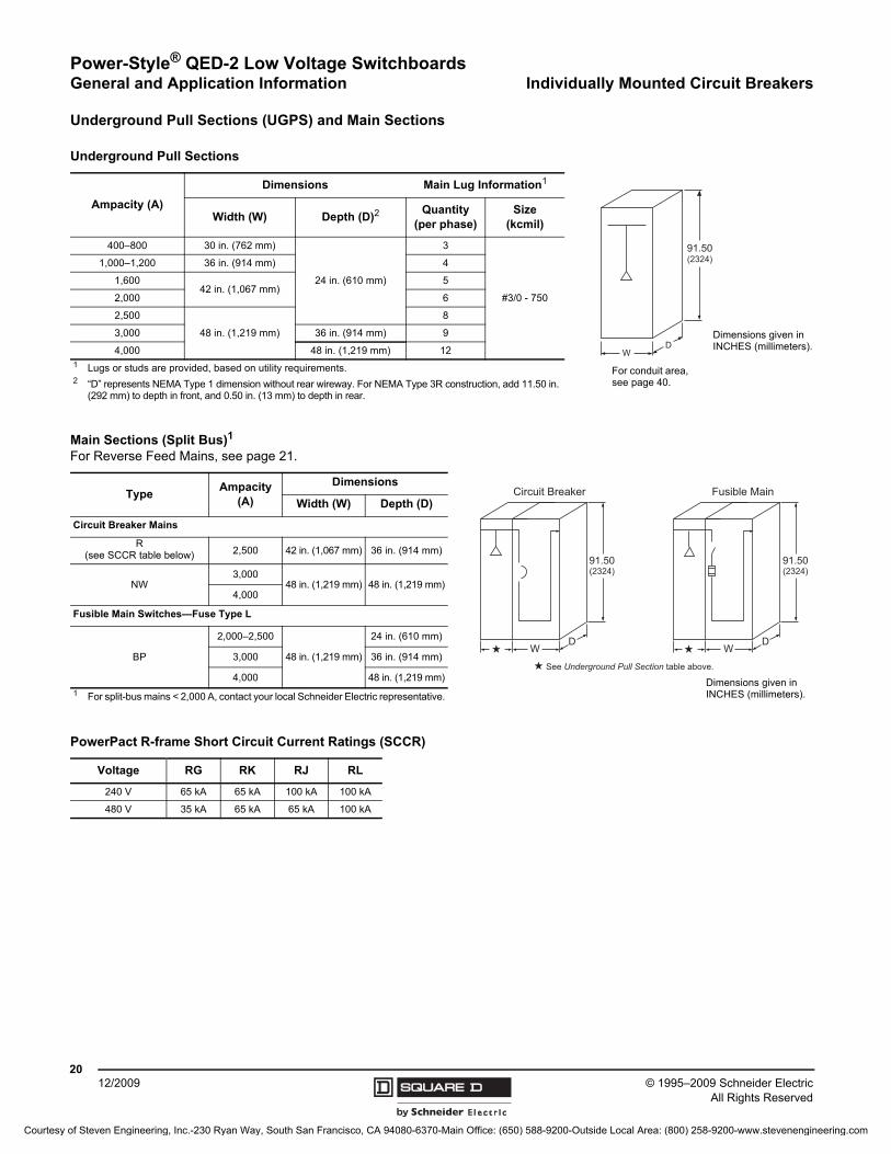
Underground Pull Sections (UGPS) and Main Sections
Underground Pull Sections
Ampacity (A)
Dimensions Main Lug Information1
Width (W) Depth (D)2Quantity
(per phase)Size
(kcmil)
400–800 30 in. (762 mm)
24 in. (610 mm)
3
#3/0 - 750
1,000–1,200 36 in. (914 mm) 4
1,60042 in. (1,067 mm)
5
2,000 6
2,500
48 in. (1,219 mm)
8
3,000 36 in. (914 mm) 9
4,000 48 in. (1,219 mm) 121 Lugs or studs are provided, based on utility requirements.2 “D” represents NEMA Type 1 dimension without rear wireway. For NEMA Type 3R construction, add 11.50 in.
(292 mm) to depth in front, and 0.50 in. (13 mm) to depth in rear.
91.50(2324)
WD
Dimensions given in INCHES (millimeters).
For conduit area, see page 40.
Main Sections (Split Bus)1
For Reverse Feed Mains, see page 21.
TypeAmpacity
(A)
Dimensions
Width (W) Depth (D)
Circuit Breaker Mains
R(see SCCR table below) 2,500 42 in. (1,067 mm) 36 in. (914 mm)
NW3,000
48 in. (1,219 mm) 48 in. (1,219 mm)4,000
Fusible Main Switches—Fuse Type L
BP
2,000–2,500
48 in. (1,219 mm)
24 in. (610 mm)
3,000 36 in. (914 mm)
4,000 48 in. (1,219 mm)
1 For split-bus mains < 2,000 A, contact your local Schneider Electric representative.
91.50(2324)
WD
Fusible Main
91.50(2324)
WD
Circuit Breaker
dd
d See Underground Pull Section table above.
Dimensions given in INCHES (millimeters).
PowerPact R-frame Short Circuit Current Ratings (SCCR)
Voltage RG RK RJ RL
240 V 65 kA 65 kA 100 kA 100 kA
480 V 35 kA 65 kA 65 kA 100 kA
Courtesy of Steven Engineering, Inc.-230 Ryan Way, South San Francisco, CA 94080-6370-Main Office: (650) 588-9200-Outside Local Area: (800) 258-9200-www.stevenengineering.com
Power-Style® QED-2 Low Voltage SwitchboardsIndividually Mounted Circuit Breakers General and Application Information
2112/2009© 1995–2009 Schneider Electric
All Rights Reserved
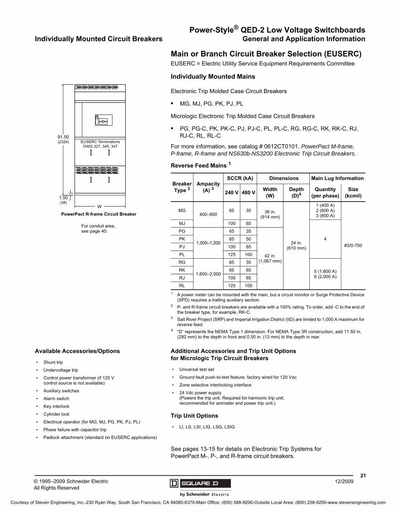
Main or Branch Circuit Breaker Selection (EUSERC)EUSERC = Electric Utility Service Equipment Requirements Committee
Individually Mounted Mains
Electronic Trip Molded Case Circuit Breakers
• MG, MJ, PG, PK, PJ, PL
Micrologic Electronic Trip Molded Case Circuit Breakers
• PG, PG-C, PK, PK-C, PJ, PJ-C, PL, PL-C, RG, RG-C, RK, RK-C, RJ, RJ-C, RL, RL-C
For more information, see catalog # 0612CT0101, PowerPact M-frame, P-frame, R-frame and NS630b-NS3200 Electronic Trip Circuit Breakers.
See pages 13-15 for details on Electronic Trip Systems for PowerPact M-, P-, and R-frame circuit breakers.
1.50(38)
91.50(2324)
W
EUSERC TerminationsDWG 327, 345, 347
PowerPact R-frame Circuit Breaker
For conduit area, see page 40.
Reverse Feed Mains 1
1 A power meter can be mounted with the main, but a circuit monitor or Surge Protective Device (SPD) requires a trailing auxiliary section.
Breaker Type 2
2 P- and R-frame circuit breakers are available with a 100% rating. To order, add -C to the end of the breaker type, for example, RK-C.
Ampacity(A) 3
3 Salt River Project (SRP) and Imperial Irrigation District (IID) are limited to 1,000 A maximum for reverse feed.
SCCR (kA) Dimensions Main Lug Information
240 V 480 VWidth
(W)Depth (D)4
4 “D” represents the NEMA Type 1 dimension. For NEMA Type 3R construction, add 11.50 in. (292 mm) to the depth in front and 0.50 in. (13 mm) to the depth in rear.
Quantity(per phase)
Size(kcmil)
MG400–800
65 35 36 in.(914 mm)
24 in. (610 mm)
1 (400 A)2 (600 A)3 (800 A)
#3/0-750
MJ 100 65
4
PG
1,000–1,200
65 35
42 in.(1,067 mm)
PK 65 50
PJ 100 65
PL 125 100
RG
1,600–2,000
65 35
5 (1,600 A)6 (2,000 A)
RK 65 65
RJ 100 65
RL 125 100
Available Accessories/Options
• Shunt trip
• Undervoltage trip
• Control power transformer (if 120 V control source is not available)
• Auxiliary switches
• Alarm switch
• Key interlock
• Cylinder lock
• Electrical operator (for MG, MJ, PG, PK, PJ, PL)
• Phase failure with capacitor trip
• Padlock attachment (standard on EUSERC applications)
Additional Accessories and Trip Unit Options for Micrologic Trip Circuit Breakers
• Universal test set
• Ground fault push-to-test feature, factory wired for 120 Vac
• Zone selective interlocking interface
• 24 Vdc power supply(Powers the trip unit. Required for harmonic trip unit; recommended for ammeter and power trip unit.)
Trip Unit Options
• LI, LS, LSI, LIG, LSG, LSIG
Courtesy of Steven Engineering, Inc.-230 Ryan Way, South San Francisco, CA 94080-6370-Main Office: (650) 588-9200-Outside Local Area: (800) 258-9200-www.stevenengineering.com
Power-Style® QED-2 Low Voltage SwitchboardsGeneral and Application Information Group Mounted Circuit Breakers
© 1995–2009 Schneider ElectricAll Rights Reserved
2212/2009
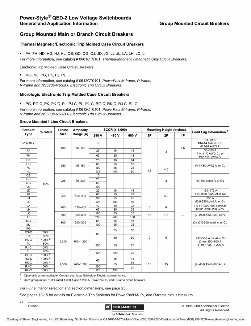
Group Mounted Main or Branch Circuit Breakers
Thermal Magnetic/Electronic Trip Molded Case Circuit Breakers
• FA, FH, HD, HG, HJ, HL, QB, QD, QG, QJ, JD, JG, JJ, JL, LA, LH, LC, LI
For more information, see catalog # 0601CT9101, Thermal-Magnetic / Magnetic Only Circuit Breakers.
Electronic Trip Molded Case Circuit Breakers
• MG, MJ, PG, PK, PJ, PL
For more information, see catalog # 0612CT0101, PowerPact M-frame, P-frame, R-frame and NS630b-NS3200 Electronic Trip Circuit Breakers.
Micrologic Electronic Trip Molded Case Circuit Breakers
• PG, PG-C, PK, PK-C, PJ, PJ-C, PL, PL-C, RG-C, RK-C, RJ-C, RL-C
For more information, see catalog # 0612CT0101, PowerPact M-frame, P-frame, R-frame and NS630b-NS3200 Electronic Trip Circuit Breakers.
For I-Line interior selection and section dimensions, see page 23.
See pages 13-15 for details on Electronic Trip Systems for PowerPact M- P-, and R-frame circuit breakers.
Group Mounted I-Line Circuit Breakers
Breaker Type
% ratedFrame Size
Ampacity Range (A)
SCCR (x 1,000) Mounting Height (inches)Load Lug Information 1
1 Optional lugs are available. Contact your local Schneider Electric representative.
240 V 480 V 600 V 3P 2P 1P
FA (240 V)
80%
100 15–100
10 — —
4.5
31.5
15–30 A#14-#4 AWG Cu or
#12-#4 AWG Al
FA 25 18 14 35–100 A#14-#1/0 AWG Cu or
#12-#1/0 AWG AlFH 65 25 18
HD
150 15–150
25 18 14
—
#14-#3/0 AWG Al or CuHG 65 35 18HJ 100 65 25
4.5HL 125 100 50QB
225 70–225
10
— — 3 #4-300 kcmil Al or CuQD 25QG 65QJ 100JD
250 150–250
25 18 14
4.5
150–175 A#1/0-#4/0 AWG Al or CuJG 65 35 18
JJ 100 65 25 200 A#3/0-350 kcmil Al or CuJL 125 100 50
LA400 125–400
42 30 226 6
(1) #1 AWG-600 kcmil or(2) #1 AWG-250 kcmilLH 65 35 25
LC600 300–600
100 65 357.5 7.5 (2) #4/0 AWG-500 kcmil
LI 200 200 100MG
800 300–80065 35 18
9 9
(3) #3/0-500 kcmil Al or CuMJ 100 65 25PG
1,200 100–1,200
6535 18
#3/0-500 kcmil Al or Cu(3) for 250–800 A
(4) for 1,000–1,200 A
PG-C 100% 2
2 Can't group mount 100% rated 1,000 A and 1,200 A PowerPact P- and R-frame circuit breakers.
PK 80%50 50
PK-C 100% 2
PJ 80%100 65 25
PJ-C 100% 2
PL 80%125 100 25
PL-C 100% 2
RG-C 100% 2
2,500 240–1,20065
35 18
15 15 (4) #3/0 AWG-600 kcmilRK-C 100% 2
6565
RJ-C 100% 2 10025
RL-C 100% 2 125 100
Courtesy of Steven Engineering, Inc.-230 Ryan Way, South San Francisco, CA 94080-6370-Main Office: (650) 588-9200-Outside Local Area: (800) 258-9200-www.stevenengineering.com
Power-Style® QED-2 Low Voltage SwitchboardsQuick Layout Guide General and Application Information
2312/2009© 1995–2009 Schneider Electric
All Rights Reserved
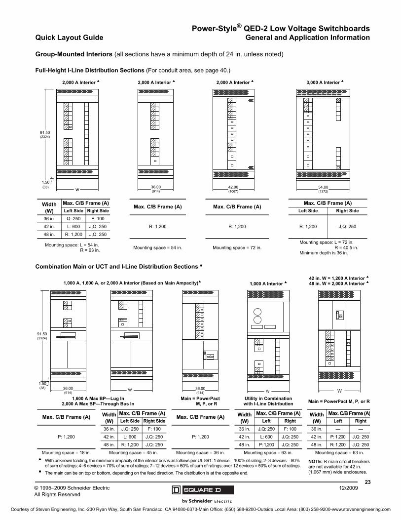
Group-Mounted Interiors (all sections have a minimum depth of 24 in. unless noted)
Full-Height I-Line Distribution Sections (For conduit area, see page 40.)
Combination Main or UCT and I-Line Distribution Sections b
w
91.50(2324)
1.50(38) 36.00
(914)42.00(1067)
54.00(1372)
Width (W)
Max. C/B Frame (A)Max. C/B Frame (A) Max. C/B Frame (A)
Max. C/B Frame (A)
Left Side Right Side Left Side Right Side
36 in. Q: 250 F: 100
R: 1,200 R: 1,200 R: 1,200 J,Q: 25042 in. L: 600 J,Q: 250
48 in. R: 1,200 J,Q: 250
Mounting space: L = 54 in.R = 63 in.
Mounting space = 54 in. Mounting space = 72 in.Mounting space: L = 72 in.
R = 40.5 in.Minimum depth is 36 in.
2,000 A Interior a 3,000 A Interior a2,000 A Interior a2,000 A Interior a
91.50(2324)
1.50(38) 36.00
(914)W 36.00
(914) WW
Max. C/B Frame (A) Width (W)
Max. C/B Frame (A)Max. C/B Frame (A) Width
(W)
Max. C/B Frame (A) Width (W)
Max. C/B Frame (A)
Left Side Right Side Left Right Left Right
P: 1,200
36 in. J,Q: 250 F: 100
P: 1,200
36 in. J,Q: 250 F: 100 36 in. — —
42 in. L: 600 J,Q: 250 42 in. L: 600 J,Q: 250 42 in. P: 1,200 J,Q: 250
48 in. R: 1,200 J,Q: 250 48 in. P: 1,200 J,Q: 250 48 in. R: 1,200 J,Q: 250
Mounting space = 18 in. Mounting space = 45 in. Mounting space = 36 in. Mounting space = 63 in. Mounting space = 63 in.a With unknown loading, the minimum ampacity of the interior bus is as follows per UL 891: 1 device = 100% of rating; 2–3 devices = 80%
of sum of ratings; 4–6 devices = 70% of sum of ratings; 7–12 devices = 60% of sum of ratings; over 12 devices = 50% of sum of ratings.b The main can be on top or bottom, depending on the feed direction. The distribution is at the opposite end.
NOTE: R main circuit breakers are not available for 42 in. (1,067 mm) wide enclosures.
1,000 A, 1,600 A, or 2,000 A Interior (Based on Main Ampacity)a42 in. W = 1,200 A Interior a
48 in. W = 2,000 A Interior a1,000 A Interior a
Main = PowerPactM, P, or R
1,600 A Max BP—Lug In2,000 A Max BP—Through Bus In Main = PowerPact M, P, or R
Utility in Combination with I-Line Distribution
Courtesy of Steven Engineering, Inc.-230 Ryan Way, South San Francisco, CA 94080-6370-Main Office: (650) 588-9200-Outside Local Area: (800) 258-9200-www.stevenengineering.com
Power-Style® QED-2 Low Voltage SwitchboardsGeneral and Application Information Quick Layout Guide
© 1995–2009 Schneider ElectricAll Rights Reserved
2412/2009
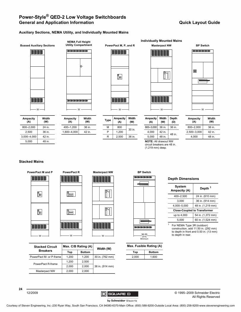
Auxiliary Sections, NEMA Utility, and Individually Mounted Mains
W W W W
Ampacity (A)
Width(W)
Ampacity (A)
Width(W)
TypeAmpacity
(A)Width (W)
Ampacity (A)
Width (W)
Depth (D)
Ampacity (A)
Width(W)
800–2,000 24 in. 400–1,200 36 in. M 80030 in.
800–3,000 36 in. 36 in. 800–2,000 36 in.
2,500 36 in. 1,600–4,000 42 in. P 1,200 4,000 42 in.48 in.
2,500–3,000 42 in.
3,000–4,000 42 in. R 2,500 36 in. 5,000 48 in. 4,000 48 in.
5,000 48 in. NOTE: All drawout NW circuit breakers are 48 in. (1,219 mm) deep.
Bussed Auxiliary Sections BP SwitchPowerPact M, P, and RNEMA Full Height
Utility Compartment
W
Masterpact NW
Individually Mounted Mains
Stacked Mains
W W W 36.00(914)
Minimum
Stacked Circuit Breakers
Max. C/B Rating (A)Width (W)
Max. Fusible Rating (A)
Top Bottom Top Bottom
PowerPact M- or P-frame 1,200 1,200 30 in. (762 mm) 2,000 1,600
PowerPact R-frame1,200 2,500
36 in. (914 mm)2,000 2,000
Masterpact NW 2,000 2,000
PowerPact M and P
Depth Dimensions
System Ampacity (A)
Depth 1
1 For NEMA Type 3R (outdoor) construction, add 11.50 in. (292 mm) to depth in front and 0.50 in. (13 mm) to depth in rear.
400–2,500 24 in. (610 mm)
3,000 36 in. (914 mm)
4,000–5,000 48 in. (1,219 mm)
Close-Coupled to Transformer
up to 4,000 54 in. (1,372 mm)
5,000 60 in. (1,524 mm)
BP SwitchMasterpact NWPowerPact R
Courtesy of Steven Engineering, Inc.-230 Ryan Way, South San Francisco, CA 94080-6370-Main Office: (650) 588-9200-Outside Local Area: (800) 258-9200-www.stevenengineering.com
Power-Style® QED-2 Low Voltage SwitchboardsQuick Layout Guide General and Application Information
2512/2009© 1995–2009 Schneider Electric
All Rights Reserved
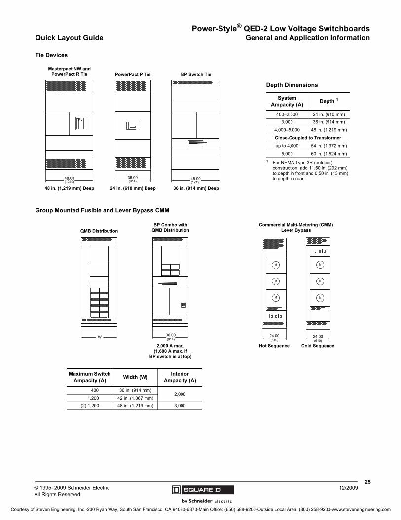
Tie Devices
48.00(1219)
36.00(914) 48.00
(1219)
Masterpact NW and PowerPact R Tie
Depth Dimensions
System Ampacity (A)
Depth 1
1 For NEMA Type 3R (outdoor) construction, add 11.50 in. (292 mm) to depth in front and 0.50 in. (13 mm) to depth in rear.
400–2,500 24 in. (610 mm)
3,000 36 in. (914 mm)
4,000–5,000 48 in. (1,219 mm)
Close-Coupled to Transformer
up to 4,000 54 in. (1,372 mm)
5,000 60 in. (1,524 mm)
BP Switch TiePowerPact P Tie
48 in. (1,219 mm) Deep 36 in. (914 mm) Deep24 in. (610 mm) Deep
Group Mounted Fusible and Lever Bypass CMM
W 36.00(914)
M
M
M
24.00(610)
Maximum Switch Ampacity (A)
Width (W)Interior
Ampacity (A)
400 36 in. (914 mm)2,000
1,200 42 in. (1,067 mm)
(2) 1,200 48 in. (1,219 mm) 3,000
QMB DistributionBP Combo with
QMB Distribution
M
M
M
24.00(610)
Commercial Multi-Metering (CMM)Lever Bypass
2,000 A max.(1,600 A max. if
BP switch is at top)
Cold SequenceHot Sequence
Courtesy of Steven Engineering, Inc.-230 Ryan Way, South San Francisco, CA 94080-6370-Main Office: (650) 588-9200-Outside Local Area: (800) 258-9200-www.stevenengineering.com
Power-Style® QED-2 Low Voltage SwitchboardsGeneral and Application Information Quick Layout Guide
© 1995–2009 Schneider ElectricAll Rights Reserved
2612/2009
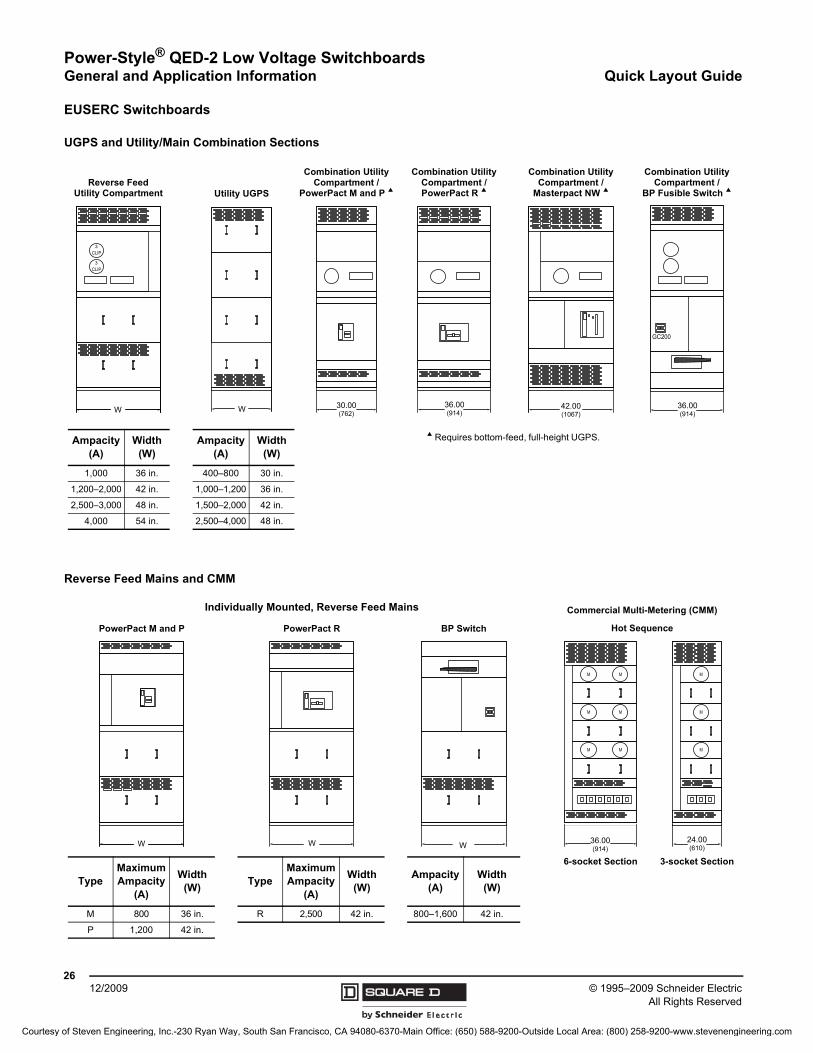
EUSERC Switchboards
UGPS and Utility/Main Combination Sections
W 30.00(762)
36.00(914)
CLIP
CLIP
3
3
W 36.00(914)
GC200
Ampacity (A)
Width (W)
Ampacity (A)
Width (W)
a Requires bottom-feed, full-height UGPS.
1,000 36 in. 400–800 30 in.
1,200–2,000 42 in. 1,000–1,200 36 in.
2,500–3,000 48 in. 1,500–2,000 42 in.
4,000 54 in. 2,500–4,000 48 in.
Utility UGPS
Combination Utility Compartment / PowerPact R a
Combination Utility Compartment /
PowerPact M and P a
42.00(1067)
Combination Utility Compartment /
Masterpact NW aReverse Feed
Utility Compartment
Combination Utility Compartment /
BP Fusible Switch a
Reverse Feed Mains and CMM
W W
M
M
MM
M
M
36.00(914)W
PowerPact M and P BP SwitchPowerPact R
M
M
M
24.00(610)
Commercial Multi-Metering (CMM)
Hot Sequence
3-socket Section6-socket Section
TypeMaximum Ampacity
(A)
Width (W)
TypeMaximum Ampacity
(A)
Width (W)
Ampacity (A)
Width (W)
M 800 36 in. R 2,500 42 in. 800–1,600 42 in.
P 1,200 42 in.
Individually Mounted, Reverse Feed Mains
Courtesy of Steven Engineering, Inc.-230 Ryan Way, South San Francisco, CA 94080-6370-Main Office: (650) 588-9200-Outside Local Area: (800) 258-9200-www.stevenengineering.com
Power-Style® QED-2 Low Voltage SwitchboardsIndividually Mounted Fusible Switches General and Application Information
2712/2009© 1995–2009 Schneider Electric
All Rights Reserved
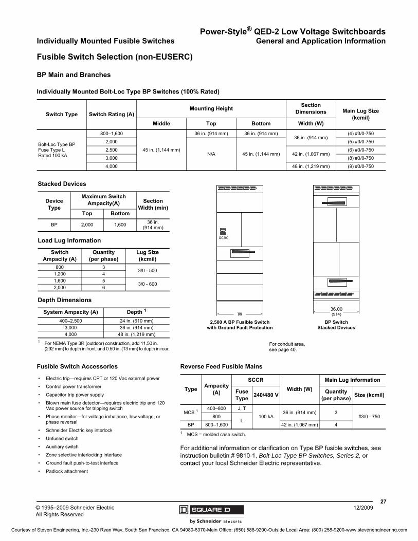
Fusible Switch Selection (non-EUSERC)
BP Main and Branches
For additional information or clarification on Type BP fusible switches, see instruction bulletin # 9810-1, Bolt-Loc Type BP Switches, Series 2, or contact your local Schneider Electric representative.
Individually Mounted Bolt-Loc Type BP Switches (100% Rated)
Switch Type Switch Rating (A)Mounting Height
Section Dimensions Main Lug Size
(kcmil)Middle Top Bottom Width (W)
Bolt-Loc Type BP Fuse Type L Rated 100 kA
800–1,600
45 in. (1,144 mm)
36 in. (914 mm) 36 in. (914 mm)36 in. (914 mm)
(4) #3/0-750
2,000
N/A 45 in. (1,144 mm)
(5) #3/0-750
2,50042 in. (1,067 mm)
(6) #3/0-750
3,000 (8) #3/0-750
4,000 48 in. (1,219 mm) (9) #3/0-750
Stacked Devices
Device Type
Maximum Switch Ampacity(A) Section
Width (min)Top Bottom
BP 2,000 1,600 36 in. (914 mm)
Load Lug Information
Switch Ampacity (A)
Quantity (per phase)
Lug Size (kcmil)
800 33/0 - 500
1,200 4
1,600 53/0 - 600
2,000 6
Depth Dimensions
System Ampacity (A) Depth 1
1 For NEMA Type 3R (outdoor) construction, add 11.50 in. (292 mm) to depth in front, and 0.50 in. (13 mm) to depth in rear.
400–2,500 24 in. (610 mm)
3,000 36 in. (914 mm)
4,000 48 in. (1,219 mm)
W
GC200
36.00(914)
2,500 A BP Fusible Switch with Ground Fault Protection
For conduit area, see page 40.
BP SwitchStacked Devices
Fusible Switch Accessories
• Electric trip—requires CPT or 120 Vac external power
• Control power transformer
• Capacitor trip power supply
• Blown main fuse detector—requires electric trip and 120 Vac power source for tripping switch
• Phase monitor—for voltage imbalance, low voltage, or phase reversal
• Schneider Electric key interlock
• Unfused switch
• Auxiliary switch
• Zone selective interlocking interface
• Ground fault push-to-test interface
• Padlock attachment
Reverse Feed Fusible Mains
TypeAmpacity
(A)
SCCR
Width (W)
Main Lug Information
Fuse Type
240/480 VQuantity
(per phase)Size (kcmil)
MCS 1
1 MCS = molded case switch.
400–800 J, T
100 kA36 in. (914 mm) 3
#3/0 - 750800L
BP 800–1,600 42 in. (1,067 mm) 4
Courtesy of Steven Engineering, Inc.-230 Ryan Way, South San Francisco, CA 94080-6370-Main Office: (650) 588-9200-Outside Local Area: (800) 258-9200-www.stevenengineering.com
Power-Style® QED-2 Low Voltage SwitchboardsGeneral and Application Information Group Mounted Fusible Switches
© 1995–2009 Schneider ElectricAll Rights Reserved
2812/2009
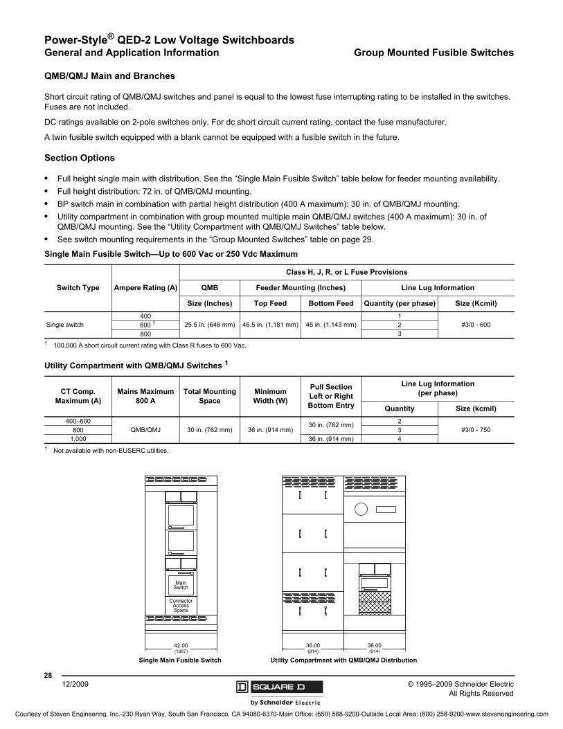
QMB/QMJ Main and Branches
Short circuit rating of QMB/QMJ switches and panel is equal to the lowest fuse interrupting rating to be installed in the switches. Fuses are not included.
DC ratings available on 2-pole switches only. For dc short circuit current rating, contact the fuse manufacturer.
A twin fusible switch equipped with a blank cannot be equipped with a fusible switch in the future.
Section Options
• Full height single main with distribution. See the “Single Main Fusible Switch” table below for feeder mounting availability.
• Full height distribution: 72 in. of QMB/QMJ mounting.
• BP switch main in combination with partial height distribution (400 A maximum): 30 in. of QMB/QMJ mounting.
• Utility compartment in combination with group mounted multiple main QMB/QMJ switches (400 A maximum): 30 in. of QMB/QMJ mounting. See the “Utility Compartment with QMB/QMJ Switches” table below.
• See switch mounting requirements in the “Group Mounted Switches” table on page 29.
Single Main Fusible Switch—Up to 600 Vac or 250 Vdc Maximum
Switch Type Ampere Rating (A)
Class H, J, R, or L Fuse Provisions
QMB Feeder Mounting (Inches) Line Lug Information
Size (Inches) Top Feed Bottom Feed Quantity (per phase) Size (Kcmil)
Single switch400
25.5 in. (648 mm) 46.5 in. (1,181 mm) 45 in. (1,143 mm)1
#3/0 - 600600 1
1 100,000 A short circuit current rating with Class R fuses to 600 Vac.
2
800 3
Utility Compartment with QMB/QMJ Switches 1
1 Not available with non-EUSERC utilities.
CT Comp. Maximum (A)
Mains Maximum 800 A
Total Mounting Space
MinimumWidth (W)
Pull Section Left or Right Bottom Entry
Line Lug Information(per phase)
Quantity Size (kcmil)
400–600QMB/QMJ 30 in. (762 mm) 36 in. (914 mm)
30 in. (762 mm)2
#3/0 - 750800 31,000 36 in. (914 mm) 4
42.00(1067)
ConnectorAccessSpace
MainSwitch
6
6
36.00(914)
36.00(914)
Single Main Fusible Switch Utility Compartment with QMB/QMJ Distribution
Courtesy of Steven Engineering, Inc.-230 Ryan Way, South San Francisco, CA 94080-6370-Main Office: (650) 588-9200-Outside Local Area: (800) 258-9200-www.stevenengineering.com
Power-Style® QED-2 Low Voltage SwitchboardsGroup Mounted Fusible Switches General and Application Information
2912/2009© 1995–2009 Schneider Electric
All Rights Reserved
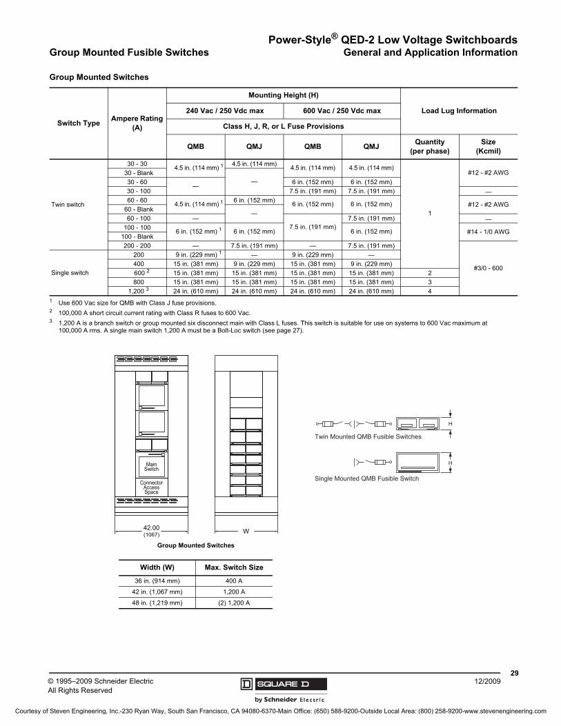
Group Mounted Switches
Switch TypeAmpere Rating
(A)
Mounting Height (H)
Load Lug Information240 Vac / 250 Vdc max 600 Vac / 250 Vdc max
Class H, J, R, or L Fuse Provisions
QMB QMJ QMB QMJ Quantity
(per phase)Size
(Kcmil)
Twin switch
30 - 304.5 in. (114 mm) 1
1 Use 600 Vac size for QMB with Class J fuse provisions.
4.5 in. (114 mm)4.5 in. (114 mm) 4.5 in. (114 mm)
1
#12 - #2 AWG30 - Blank—30 - 60
—6 in. (152 mm) 6 in. (152 mm)
30 - 100 7.5 in. (191 mm) 7.5 in. (191 mm) —60 - 60
4.5 in. (114 mm) 16 in. (152 mm)
6 in. (152 mm) 6 in. (152 mm) #12 - #2 AWG60 - Blank
—60 - 100 —
7.5 in. (191 mm)7.5 in. (191 mm) —
100 - 1006 in. (152 mm) 1 6 in. (152 mm) 6 in. (152 mm) #14 - 1/0 AWG
100 - Blank
200 - 200 — 7.5 in. (191 mm) — 7.5 in. (191 mm)
#3/0 - 600Single switch
200 9 in. (229 mm) 1 — 9 in. (229 mm) —
400 15 in. (381 mm) 9 in. (229 mm) 15 in. (381 mm) 9 in. (229 mm)
600 2
2 100,000 A short circuit current rating with Class R fuses to 600 Vac.
15 in. (381 mm) 15 in. (381 mm) 15 in. (381 mm) 15 in. (381 mm) 2
800 15 in. (381 mm) 15 in. (381 mm) 15 in. (381 mm) 15 in. (381 mm) 3
1,200 3
3 1,200 A is a branch switch or group mounted six disconnect main with Class L fuses. This switch is suitable for use on systems to 600 Vac maximum at 100,000 A rms. A single main switch 1,200 A must be a Bolt-Loc switch (see page 27).
24 in. (610 mm) 24 in. (610 mm) 24 in. (610 mm) 24 in. (610 mm) 4
42.00(1067)
ConnectorAccessSpace
MainSwitch
W
Twin Mounted QMB Fusible Switches
Single Mounted QMB Fusible Switch
H
H
Group Mounted Switches
Width (W) Max. Switch Size
36 in. (914 mm) 400 A
42 in. (1,067 mm) 1,200 A
48 in. (1,219 mm) (2) 1,200 A
Courtesy of Steven Engineering, Inc.-230 Ryan Way, South San Francisco, CA 94080-6370-Main Office: (650) 588-9200-Outside Local Area: (800) 258-9200-www.stevenengineering.com
© 1995–2009 Schneider ElectricAll Rights Reserved
Power-Style® QED-2 Low Voltage SwitchboardsGeneral and Application Information Utility Metering
3012/2009
U.S. Utilities (Non-EUSERC)
The Utilities listed are the only ones for which Schneider Electric Design Engineering currently maintains records. They are available in full height or in combination with a PowerPact M-, P-, or R-frame main breaker, or BP fusible switch unless stated. Widths are shown for each group.
Unlisted Utilities
There are two ways to have utility compartments built for utility companies that are not listed.
1. The unlisted utility company has no specific design, and just a bussed compartment in the service entrance equipment is required for installing CTs.
For this application, select the listed utility company that best meets the unlisted utility requirements and provide the name of the unlisted utility company. Schneider Electric will build the utility compartment to the design standards of the listed utility selected. The “record” drawings will show the name of the unlisted utility.
2. The unlisted utility has a specific design and does not allow deviation.
For this application, custom design and fabrication are required. The specific utility requirements will have to be provided for pricing and design.
Definitions
Cold Sequence Metering—In cold sequence metering, the main disconnecting device is placed ahead of (on the line side of) the current transformer compartment. In this arrangement, the current transformer compartment can be de-energized by switching the main circuit breaker to the OFF position.
Hot Sequence Metering—In hot sequence metering, the main disconnecting device is placed behind (on the load side of) the current transformer compartment. In this arrangement, the current transformer compartment is always energized.
AEP Group—all 42 in. wide
• American Electric Power (OH)
• Appalachian Power Company (VA)
• Columbus Southern Power (OH)
• Holy Cross Energy (CO)
• Indiana and Michigan Power (IN)
• Kansas City Power & Light Company (MO)
• Kentucky Power Company (KY)
• Kingsport Power Company (TN)
• Ohio Power Company (OH)
• Wheeling Power Company (WV)
Full Height Only (no combo)—all 42 in. wide
• Indianapolis Power & Light Company (IN) 1
• Louisville Gas and Electric Company (KY) 1
• Virginia Electric Power Company (VA) 1
Baltimore Gas & Electric 1, 2 —all 42 in. wide
1 Large tenant mains are not available for this utility.2 Can only be used in combination with a PowerPact R-frame main circuit breaker.
CILCO Group—all 36 in. wide
• Central Illinois Light Company (IL)
• Commonwealth Edison Company (IL)
• Detroit Edison Company (MI)
• Metropolitan Edison Company (PA)
• Xcel Energy Inc (MN)
NEMA Group—36 in. wide up to 1,200 A, 42 in. wide over 1,200 A
• Cincinnati Gas & Electric (OH)
• Dayton Power & Light Company (OH)
• Fort Collins, City of (CO)
• NEMA Standard Design
Cold Sequence Utilities
• New York State Electric & Gas Corp. (NY)—all 42 in. wide
• Niagara Mohawk Power (NY)—all 42 in. wide
• Northeast Utilities (CT)—all 36 in. wide
Courtesy of Steven Engineering, Inc.-230 Ryan Way, South San Francisco, CA 94080-6370-Main Office: (650) 588-9200-Outside Local Area: (800) 258-9200-www.stevenengineering.com
Power-Style® QED-2 Low Voltage SwitchboardsUtility Metering General and Application Information
3112/2009© 1995–2009 Schneider Electric
All Rights Reserved
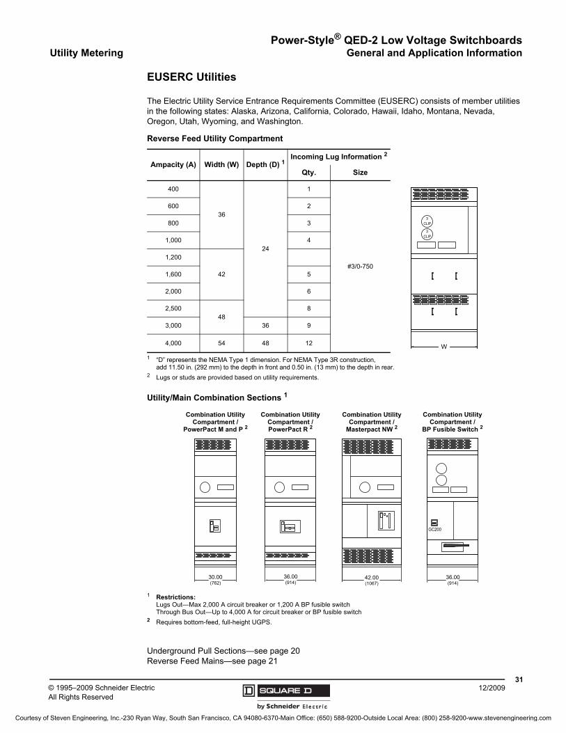
EUSERC Utilities
The Electric Utility Service Entrance Requirements Committee (EUSERC) consists of member utilities in the following states: Alaska, Arizona, California, Colorado, Hawaii, Idaho, Montana, Nevada, Oregon, Utah, Wyoming, and Washington.
Underground Pull Sections—see page 20Reverse Feed Mains—see page 21
Reverse Feed Utility Compartment
Ampacity (A) Width (W) Depth (D) 1
1 “D” represents the NEMA Type 1 dimension. For NEMA Type 3R construction, add 11.50 in. (292 mm) to the depth in front and 0.50 in. (13 mm) to the depth in rear.
Incoming Lug Information 2
2 Lugs or studs are provided based on utility requirements.
Qty. Size
400
36
24
1
#3/0-750
600 2
800 3
1,000 4
1,200
421,600 5
2,000 6
2,50048
8
3,000 36 9
4,000 54 48 12
Utility/Main Combination Sections 1
1 Restrictions:Lugs Out—Max 2,000 A circuit breaker or 1,200 A BP fusible switchThrough Bus Out—Up to 4,000 A for circuit breaker or BP fusible switch
2 Requires bottom-feed, full-height UGPS.
CLIP
CLIP
3
3
W
30.00(762)
36.00(914)
36.00(914)
GC200
Combination Utility Compartment / PowerPact R 2
Combination Utility Compartment /
PowerPact M and P 2
42.00(1067)
Combination Utility Compartment /
Masterpact NW 2
Combination Utility Compartment /
BP Fusible Switch 2
Courtesy of Steven Engineering, Inc.-230 Ryan Way, South San Francisco, CA 94080-6370-Main Office: (650) 588-9200-Outside Local Area: (800) 258-9200-www.stevenengineering.com
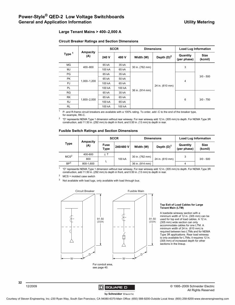
© 1995–2009 Schneider ElectricAll Rights Reserved
Power-Style® QED-2 Low Voltage SwitchboardsGeneral and Application Information Utility Metering
3212/2009
Large Tenant Mains > 400–2,000 A
Circuit Breaker Ratings and Section Dimensions
Type 1
1 P- and R-frame circuit breakers are available with a 100% rating. To order, add -C to the end of the breaker type, for example, RK-C.
Ampacity (A)
SCCR Dimensions Load Lug Information
240 V 480 V Width (W) Depth (D)2
2 “D” represents NEMA Type 1 dimension without rear wireway. For rear wireway add 12 in. (305 mm) to depth. For NEMA Type 3R construction, add 11.50 in. (292 mm) to depth in front, and 0.50 in. (13 mm) to depth in rear.
Quantity(per phase)
Size(kcmil)
MG400–800
65 kA 35 kA30 in. (762 mm)
24 in. (610 mm)
3
3/0 - 500
MJ 100 kA 65 kA
PG
1,000–1,200
65 kA 35 kA
36 in. (914 mm)
4PK 65 kA 50 kA
PJ 100 kA 65 kA
PL 100 kA 100 kA
RG
1,600–2,000
65 kA 35 kA
6 3/0 - 750RK 65 kA 65 kA
RJ 100 kA 65 kA
RL 100 kA 100 kA
Fusible Switch Ratings and Section Dimensions
TypeAmpacity
(A)
SCCR Dimensions Load Lug Information
Fuse Type
240/480 V Width (W) Depth (D)1
1 “D” represents NEMA Type 1 dimension without rear wireway. For rear wireway add 12 in. (305 mm) to depth. For NEMA Type 3R construction, add 11.50 in. (292 mm) to depth in front, and 0.50 in. (13 mm) to depth in rear.
Quantity(per phase)
Size(kcmil)
MCS2
2 MCS = molded case switch
400-600 J, T
100 kA30 in. (762 mm)
24 in. (610 mm)3
3/0 - 500800L
BP3
3 Not available with load lugs, only available with load through bus.
800-1,600 36 in. (914 mm) 4
91.50(2324)
WD
Fusible Main
91.50(2324)
WD
Circuit Breaker
Top Exit of Load Cables for Large Tenant Main (LTM)
A loadside wireway section with a minimum width of 12 in. (305 mm) can be used for top exit of load cables. A 12 in. (305 mm) wide section can only accommodate cables for one LTM. A minimum width of 24 in. (610 mm) is required between two LTMs and for NEMA Type 3R applications. Rear load wireway is only available for LTMs; it requires 12 in. (305 mm) of increased depth for other sections in the lineup.
For conduit area, see page 40.
Courtesy of Steven Engineering, Inc.-230 Ryan Way, South San Francisco, CA 94080-6370-Main Office: (650) 588-9200-Outside Local Area: (800) 258-9200-www.stevenengineering.com

Power-Style® QED-2 Low Voltage SwitchboardsCommercial Multi-Metering General and Application Information
3312/2009© 1995–2009 Schneider Electric
All Rights Reserved
EUSERC Meter Section—Tenant Mains 200 A (Hot Sequence)
Circuit Breaker Ratings Fusible Pullout Ratings
TypeAmpacity
(A)SCCR Load Lug
Information 1
1 Neutral lug terminations are #6 - 350 kcmil.
TypeAmpacity
(A)SCCR Load Lug
Information 1240 V 480 V 240 V 480 VFAL
60–10022 kA 18 kA #12 - 1/0 AWG
Al or CuFTL3100 100 100 kA N/A #14 - 1/0 AWG
FHL 65 kA 18 kA FTL3200 200 100 kA N/A #4 - 250 kcmilHJL 100 kA 65 kA
#4-3/0 kcmil Al or Cu
FTL43060 60 N/A 100 kA #14 - #2HDL
110–150
22 kA 18 kA FTL43100 100 N/A 100 kA #14 - 1/0 AWGHGL 65 kA 35 kA FTL43200 200 N/A 100 kA 1/0 AWG - 300 kcmil HJL 100 kA 65 kAHLL 100 kA 100 kAJDL
175–200
22 kA 18 kA
#4 - 300 kcmilAl or Cu
JGL 65 kA 35 kAJJL 100 kA 65 kAJLL 100 kA 100 kA
QDL2
2 A shunt trip is not available for PowerPact Q-frame circuit breakers.
110–20022 kA N/A
QGL2 65 kA N/AQJL2 100 kA N/A
3.00(76)
24.00(610)
2.50(64)
2.50(64)
2.50(64)
24.00(610)
2.50(64)
2.50(64)
2.50(64)
8.87(225)
19.00(483)
24.00(610)
91.50(2324)
1.50(38)
3.00(76)
13.00(330)
24.00(610)
2.50(64)
16.00(406)
24.00(610)
24.00(610)
EUSERCDWG 306
M
M
M
2.50(64)
8.87(225)
31.00(787)
91.50(2324)
1.50(38)
13.00(330)
28.00(711)
36.00(914)
36.00(914)
Top View
Floor Plan
EUSERC DWG 306
M
M
M
M
M
M
3-Socket Main 6-Socket Main
Front Front
Front Front
Top Exit of Load Cables
Tenant metering sections come standard with a front accessible loadside wireway in each section for routing of load cables for top exit. Rear load wireway is not required for top exit applications.
Depth Dimensions
System Ampacity (A) Depth 1
1 For NEMA Type 3R (outdoor) construction, add 11.50 in. (292 mm) to depth in front, and 0.50 in. (13 mm) to depth in rear.
400–2,500 24 in. (610 mm)
3,000 36 in. (914 mm)
4,000 48 in. (1,219 mm)
Loadsidewireway
Customer-accessible
area
Conduit
Area
Dimensions given in INCHES (millimeters).
Courtesy of Steven Engineering, Inc.-230 Ryan Way, South San Francisco, CA 94080-6370-Main Office: (650) 588-9200-Outside Local Area: (800) 258-9200-www.stevenengineering.com
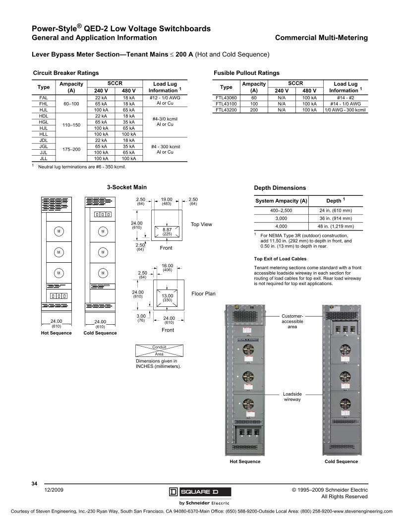
Power-Style® QED-2 Low Voltage SwitchboardsGeneral and Application Information Commercial Multi-Metering
© 1995–2009 Schneider ElectricAll Rights Reserved
3412/2009
Lever Bypass Meter Section—Tenant Mains 200 A (Hot and Cold Sequence)
Circuit Breaker Ratings Fusible Pullout Ratings
TypeAmpacity
(A)SCCR Load Lug
Information 1
1 Neutral lug terminations are #6 - 350 kcmil.
TypeAmpacity
(A)SCCR Load Lug
Information 1240 V 480 V 240 V 480 VFAL
60–10022 kA 18 kA #12 - 1/0 AWG
Al or CuFTL43060 60 N/A 100 kA #14 - #2
FHL 65 kA 18 kA FTL43100 100 N/A 100 kA #14 - 1/0 AWGHJL 100 kA 65 kA
#4-3/0 kcmil Al or Cu
FTL43200 200 N/A 100 kA 1/0 AWG - 300 kcmil HDL
110–150
22 kA 18 kAHGL 65 kA 35 kAHJL 100 kA 65 kAHLL 100 kA 100 kAJDL
175–200
22 kA 18 kA #4 - 300 kcmil
Al or CuJGL 65 kA 35 kAJJL 100 kA 65 kAJLL 100 kA 100 kA
M
M
M
24.00(610)
2.50(64)
2.50(64)
2.50(64)
8.87(225)
19.00(483)
24.00(610)
3.00(76)
13.00(330)
24.00(610)
2.50(64)
16.00(406)
24.00(610)
Top View
Floor Plan
Front
Front
M
M
M
24.00(610)
Top Exit of Load Cables
Tenant metering sections come standard with a front accessible loadside wireway in each section for routing of load cables for top exit. Rear load wireway is not required for top exit applications.
Depth Dimensions
System Ampacity (A) Depth 1
1 For NEMA Type 3R (outdoor) construction, add 11.50 in. (292 mm) to depth in front, and 0.50 in. (13 mm) to depth in rear.
400–2,500 24 in. (610 mm)
3,000 36 in. (914 mm)
4,000 48 in. (1,219 mm)
3-Socket Main
Loadside wireway
Customer- accessible
area
Cold SequenceHot Sequence
Cold SequenceHot Sequence
Conduit
Area
Dimensions given in INCHES (millimeters).
Courtesy of Steven Engineering, Inc.-230 Ryan Way, South San Francisco, CA 94080-6370-Main Office: (650) 588-9200-Outside Local Area: (800) 258-9200-www.stevenengineering.com
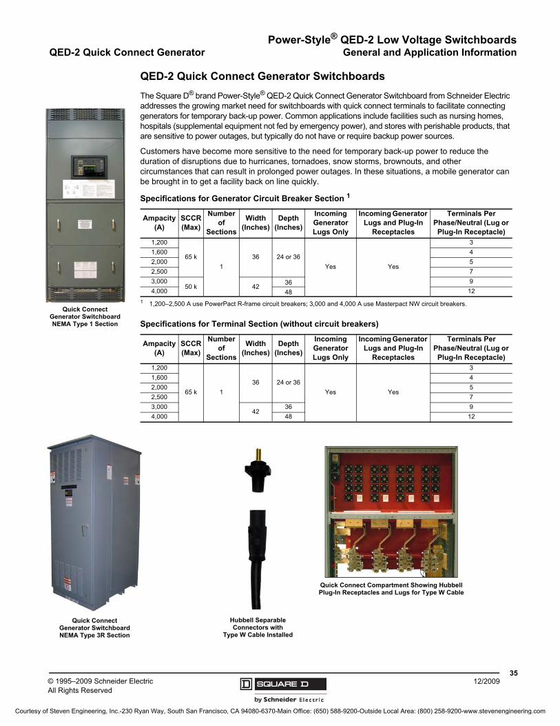
Power-Style® QED-2 Low Voltage SwitchboardsQED-2 Quick Connect Generator General and Application Information
3512/2009© 1995–2009 Schneider Electric
All Rights Reserved
QED-2 Quick Connect Generator Switchboards
The Square D® brand Power-Style® QED-2 Quick Connect Generator Switchboard from Schneider Electric addresses the growing market need for switchboards with quick connect terminals to facilitate connecting generators for temporary back-up power. Common applications include facilities such as nursing homes, hospitals (supplemental equipment not fed by emergency power), and stores with perishable products, that are sensitive to power outages, but typically do not have or require backup power sources.
Customers have become more sensitive to the need for temporary back-up power to reduce the duration of disruptions due to hurricanes, tornadoes, snow storms, brownouts, and other circumstances that can result in prolonged power outages. In these situations, a mobile generator can be brought in to get a facility back on line quickly.
Quick Connect Generator Switchboard NEMA Type 1 Section
Specifications for Generator Circuit Breaker Section 1
1 1,200–2,500 A use PowerPact R-frame circuit breakers; 3,000 and 4,000 A use Masterpact NW circuit breakers.
Ampacity (A)
SCCR (Max)
Number of
Sections
Width (Inches)
Depth (Inches)
Incoming Generator Lugs Only
Incoming Generator Lugs and Plug-In
Receptacles
Terminals Per Phase/Neutral (Lug or Plug-In Receptacle)
1,200
65 k
1
36 24 or 36
Yes Yes
3
1,600 4
2,000 5
2,500 7
3,00050 k 42
36 9
4,000 48 12
Specifications for Terminal Section (without circuit breakers)
Ampacity (A)
SCCR (Max)
Number of
Sections
Width (Inches)
Depth (Inches)
Incoming Generator Lugs Only
Incoming Generator Lugs and Plug-In
Receptacles
Terminals Per Phase/Neutral (Lug or Plug-In Receptacle)
1,200
65 k 1
36 24 or 36
Yes Yes
3
1,600 4
2,000 5
2,500 7
3,00042
36 9
4,000 48 12
Quick Connect Compartment Showing Hubbell Plug-In Receptacles and Lugs for Type W Cable
Hubbell Separable Connectors with
Type W Cable Installed
Quick Connect Generator Switchboard NEMA Type 3R Section
Courtesy of Steven Engineering, Inc.-230 Ryan Way, South San Francisco, CA 94080-6370-Main Office: (650) 588-9200-Outside Local Area: (800) 258-9200-www.stevenengineering.com
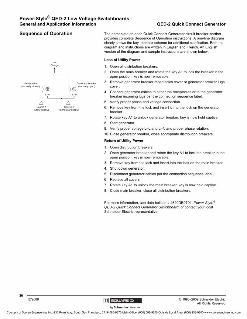
Power-Style® QED-2 Low Voltage SwitchboardsGeneral and Application Information QED-2 Quick Connect Generator
© 1995–2009 Schneider ElectricAll Rights Reserved
3612/2009
Sequence of Operation The nameplate on each Quick Connect Generator circuit breaker section provides complete Sequence of Operation instructions. A one-line diagram clearly shows the key interlock scheme for additional clarification. Both the diagram and instructions are written in English and French. An English version of the diagram and sample instructions are shown below.
Loss of Utility Power
1. Open all distribution breakers.
2. Open the main breaker and rotate the key A1 to lock the breaker in the open position; key is now removable.
3. Remove generator breaker receptacles cover or generator breaker lugs cover.
4. Connect generator cables to either the receptacles or to the generator breaker incoming lugs per the connection sequence label.
5. Verify proper phase and voltage connection.
6. Remove key from the lock and insert it into the lock on the generator breaker.
7. Rotate key A1 to unlock generator breaker; key is now held captive.
8. Start generator.
9. Verify proper voltage L–L and L–N and proper phase rotation.
10. Close generator breaker, close appropriate distribution breakers.
Return of Utility Power
1. Open distribution breakers.
2. Open generator breaker and rotate the key A1 to lock the breaker in the open position; key is now removable.
3. Remove key from the lock and insert into the lock on the main breaker.
4. Shut down generator.
5. Disconnect generator cables per the connection sequence label.
6. Replace all covers.
7. Rotate key A1 to unlock the main breaker; key is now held captive.
8. Close main breaker, close all distribution breakers.
For more information, see data bulletin # 4620DB0701, Power-Style® QED-2 Quick Connect Generator Switchboard, or contact your local Schneider Electric representative.
Load Charge
Main breaker(normally closed)
Generator breaker(normally open)
Source 1(utility supply)
Source 2(generator supply)
A 1
L – O
A1
L – O
Courtesy of Steven Engineering, Inc.-230 Ryan Way, South San Francisco, CA 94080-6370-Main Office: (650) 588-9200-Outside Local Area: (800) 258-9200-www.stevenengineering.com
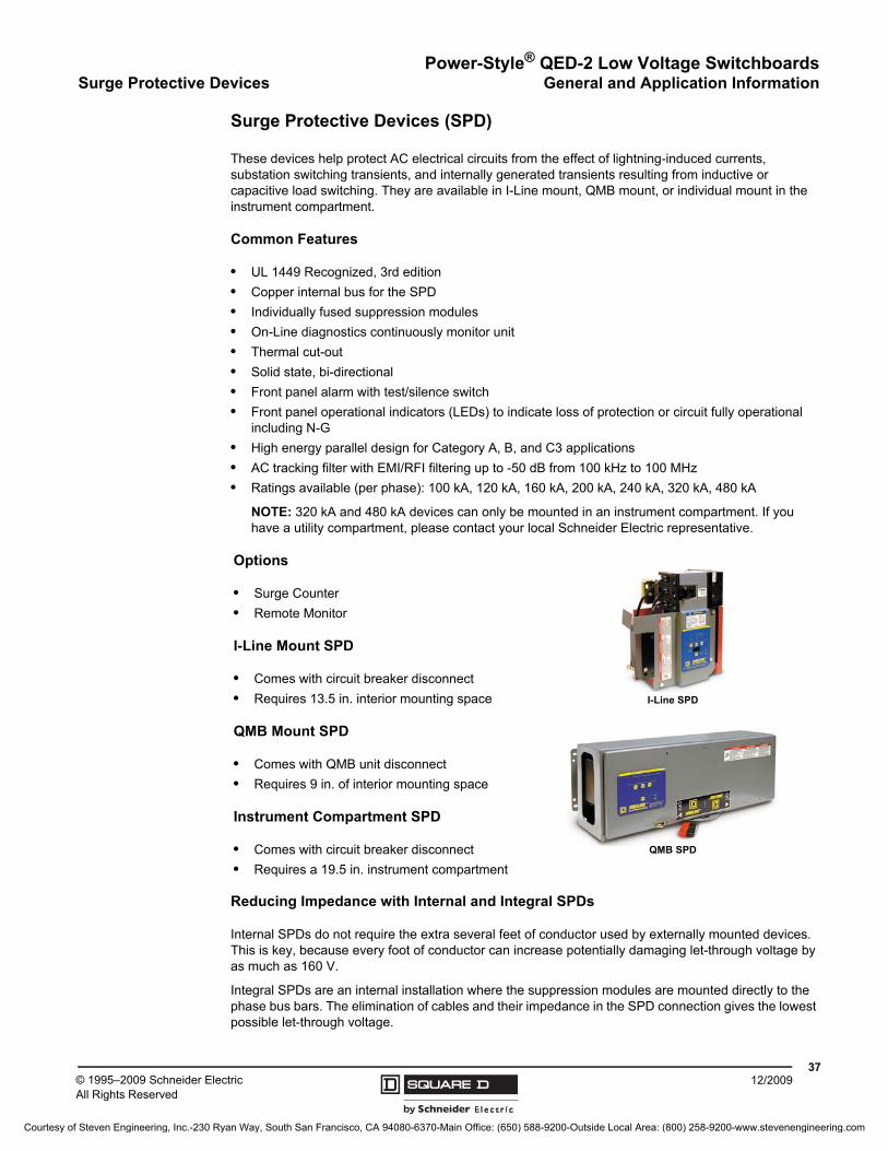
Power-Style® QED-2 Low Voltage SwitchboardsSurge Protective Devices General and Application Information
3712/2009© 1995–2009 Schneider Electric
All Rights Reserved
Surge Protective Devices (SPD)
These devices help protect AC electrical circuits from the effect of lightning-induced currents, substation switching transients, and internally generated transients resulting from inductive or capacitive load switching. They are available in I-Line mount, QMB mount, or individual mount in the instrument compartment.
Common Features
• UL 1449 Recognized, 3rd edition
• Copper internal bus for the SPD
• Individually fused suppression modules
• On-Line diagnostics continuously monitor unit
• Thermal cut-out
• Solid state, bi-directional
• Front panel alarm with test/silence switch
• Front panel operational indicators (LEDs) to indicate loss of protection or circuit fully operational including N-G
• High energy parallel design for Category A, B, and C3 applications
• AC tracking filter with EMI/RFI filtering up to -50 dB from 100 kHz to 100 MHz
• Ratings available (per phase): 100 kA, 120 kA, 160 kA, 200 kA, 240 kA, 320 kA, 480 kA
NOTE: 320 kA and 480 kA devices can only be mounted in an instrument compartment. If you have a utility compartment, please contact your local Schneider Electric representative.
Reducing Impedance with Internal and Integral SPDs
Internal SPDs do not require the extra several feet of conductor used by externally mounted devices. This is key, because every foot of conductor can increase potentially damaging let-through voltage by as much as 160 V.
Integral SPDs are an internal installation where the suppression modules are mounted directly to the phase bus bars. The elimination of cables and their impedance in the SPD connection gives the lowest possible let-through voltage.
Options
• Surge Counter
• Remote Monitor
I-Line Mount SPD
• Comes with circuit breaker disconnect
• Requires 13.5 in. interior mounting space
QMB Mount SPD
• Comes with QMB unit disconnect
• Requires 9 in. of interior mounting space
Instrument Compartment SPD
• Comes with circuit breaker disconnect
• Requires a 19.5 in. instrument compartment
I-Line SPD
QMB SPD
Courtesy of Steven Engineering, Inc.-230 Ryan Way, South San Francisco, CA 94080-6370-Main Office: (650) 588-9200-Outside Local Area: (800) 258-9200-www.stevenengineering.com
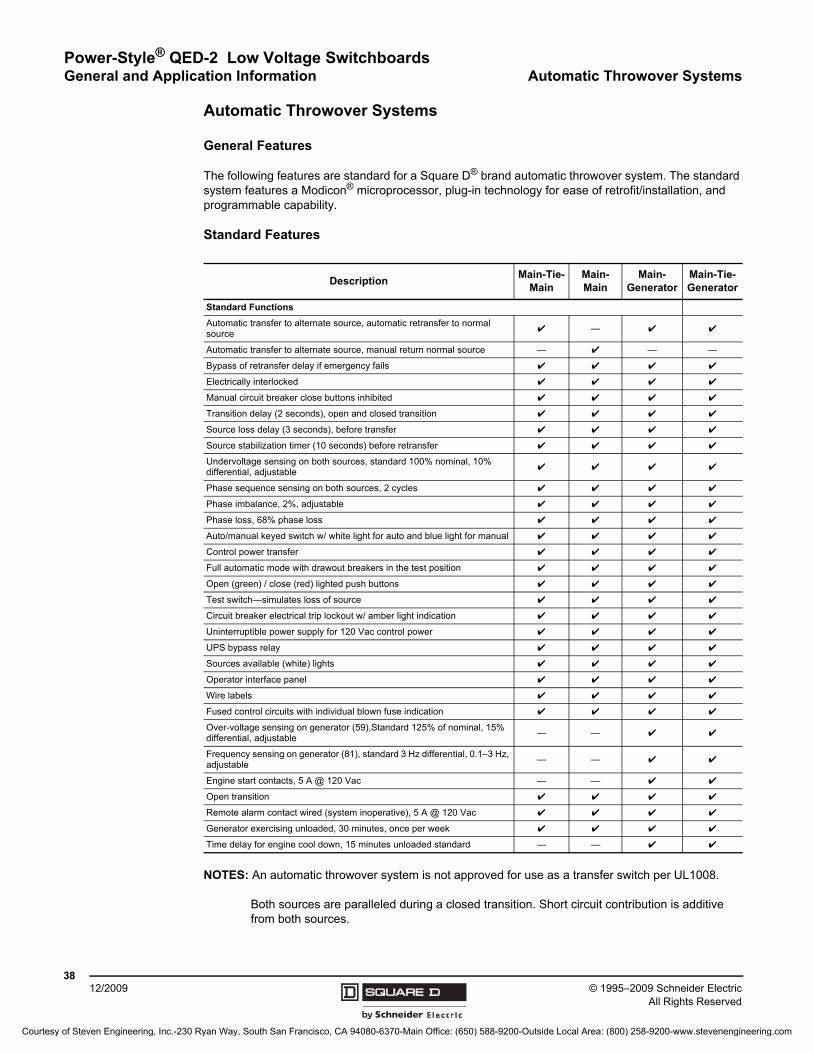
© 1995–2009 Schneider ElectricAll Rights Reserved
Power-Style® QED-2 Low Voltage SwitchboardsGeneral and Application Information Automatic Throwover Systems
3812/2009
Automatic Throwover Systems
General Features
The following features are standard for a Square D® brand automatic throwover system. The standard system features a Modicon® microprocessor, plug-in technology for ease of retrofit/installation, and programmable capability.
Standard Features
NOTES: An automatic throwover system is not approved for use as a transfer switch per UL1008.
Both sources are paralleled during a closed transition. Short circuit contribution is additive from both sources.
DescriptionMain-Tie-
MainMain-Main
Main-Generator
Main-Tie-Generator
Standard Functions
Automatic transfer to alternate source, automatic retransfer to normal source
✔ — ✔ ✔
Automatic transfer to alternate source, manual return normal source — ✔ — —
Bypass of retransfer delay if emergency fails ✔ ✔ ✔ ✔
Electrically interlocked ✔ ✔ ✔ ✔
Manual circuit breaker close buttons inhibited ✔ ✔ ✔ ✔
Transition delay (2 seconds), open and closed transition ✔ ✔ ✔ ✔
Source loss delay (3 seconds), before transfer ✔ ✔ ✔ ✔
Source stabilization timer (10 seconds) before retransfer ✔ ✔ ✔ ✔
Undervoltage sensing on both sources, standard 100% nominal, 10% differential, adjustable
✔ ✔ ✔ ✔
Phase sequence sensing on both sources, 2 cycles ✔ ✔ ✔ ✔
Phase imbalance, 2%, adjustable ✔ ✔ ✔ ✔
Phase loss, 68% phase loss ✔ ✔ ✔ ✔
Auto/manual keyed switch w/ white light for auto and blue light for manual ✔ ✔ ✔ ✔
Control power transfer ✔ ✔ ✔ ✔
Full automatic mode with drawout breakers in the test position ✔ ✔ ✔ ✔
Open (green) / close (red) lighted push buttons ✔ ✔ ✔ ✔
Test switch—simulates loss of source ✔ ✔ ✔ ✔
Circuit breaker electrical trip lockout w/ amber light indication ✔ ✔ ✔ ✔
Uninterruptible power supply for 120 Vac control power ✔ ✔ ✔ ✔
UPS bypass relay ✔ ✔ ✔ ✔
Sources available (white) lights ✔ ✔ ✔ ✔
Operator interface panel ✔ ✔ ✔ ✔
Wire labels ✔ ✔ ✔ ✔
Fused control circuits with individual blown fuse indication ✔ ✔ ✔ ✔
Over-voltage sensing on generator (59),Standard 125% of nominal, 15% differential, adjustable
— — ✔ ✔
Frequency sensing on generator (81), standard 3 Hz differential, 0.1–3 Hz, adjustable
— — ✔ ✔
Engine start contacts, 5 A @ 120 Vac — — ✔ ✔
Open transition ✔ ✔ ✔ ✔
Remote alarm contact wired (system inoperative), 5 A @ 120 Vac ✔ ✔ ✔ ✔
Generator exercising unloaded, 30 minutes, once per week ✔ ✔ ✔ ✔
Time delay for engine cool down, 15 minutes unloaded standard — — ✔ ✔
Courtesy of Steven Engineering, Inc.-230 Ryan Way, South San Francisco, CA 94080-6370-Main Office: (650) 588-9200-Outside Local Area: (800) 258-9200-www.stevenengineering.com
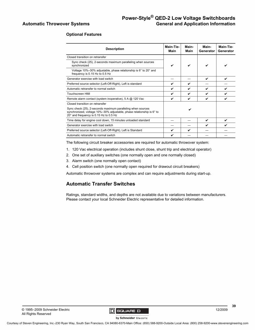
Power-Style® QED-2 Low Voltage SwitchboardsAutomatic Throwover Systems General and Application Information
3912/2009© 1995–2009 Schneider Electric
All Rights Reserved
Optional Features
The following circuit breaker accessories are required for automatic throwover system:
1. 120 Vac electrical operation (includes shunt close, shunt trip and electrical operator)
2. One set of auxiliary switches (one normally open and one normally closed)
3. Alarm switch (one normally open contact)
4. Cell position switch (one normally open required for drawout circuit breakers)
Automatic throwover systems are complex and can require adjustments during start-up.
Automatic Transfer Switches
Ratings, standard widths, and depths are not available due to variations between manufacturers. Please contact your local Schneider Electric representative for detailed information.
DescriptionMain-Tie-
MainMain-Main
Main-Generator
Main-Tie-Generator
Closed transition on retransfer
✔ ✔ ✔ ✔Sync check (25), 2-seconds maximum paralleling when sources synchronized
Voltage 10%–30% adjustable, phase relationship is 6° to 20° and frequency is 0.15 Hz to 0.5 Hz
Generator exercise with load switch — — ✔ ✔
Preferred source selector (Left-Off-Right), Left is standard ✔ ✔ — —
Automatic retransfer to normal switch ✔ ✔ ✔ ✔
Touchscreen HMI ✔ ✔ ✔ ✔
Remote alarm contact (system inoperative), 5 A @ 120 Vac ✔ ✔ ✔ ✔
Closed transition on retransfer
Sync check (25), 2-seconds maximum paralleling when sources synchronized, voltage 10%–30% adjustable, phase relationship is 6° to 20° and frequency is 0.15 Hz to 0.5 Hz
✔
Time delay for engine cool down, 15 minutes unloaded standard — — ✔ ✔
Generator exercise with load switch — — ✔ ✔
Preferred source selector (Left-Off-Right), Left is Standard ✔ ✔ — —
Automatic retransfer to normal switch ✔ — — —
Courtesy of Steven Engineering, Inc.-230 Ryan Way, South San Francisco, CA 94080-6370-Main Office: (650) 588-9200-Outside Local Area: (800) 258-9200-www.stevenengineering.com
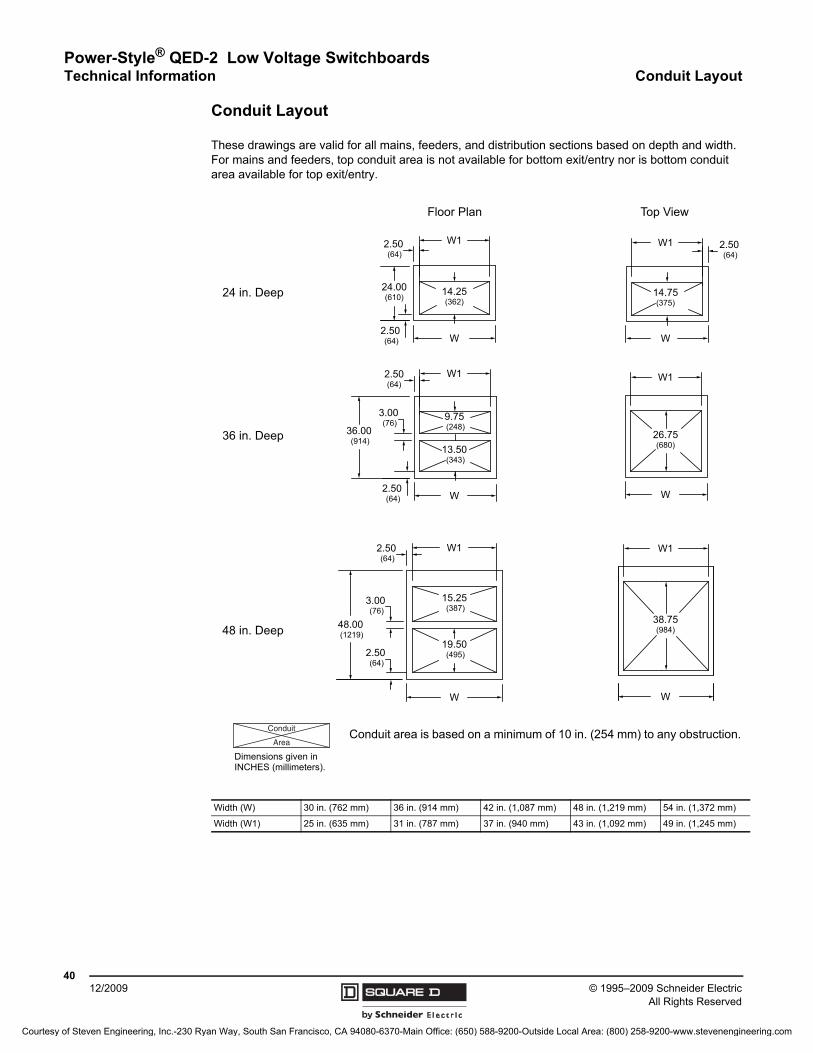
© 1995–2009 Schneider ElectricAll Rights Reserved
Power-Style® QED-2 Low Voltage SwitchboardsTechnical Information Conduit Layout
4012/2009
Conduit Layout
These drawings are valid for all mains, feeders, and distribution sections based on depth and width. For mains and feeders, top conduit area is not available for bottom exit/entry nor is bottom conduit area available for top exit/entry.
Width (W) 30 in. (762 mm) 36 in. (914 mm) 42 in. (1,087 mm) 48 in. (1,219 mm) 54 in. (1,372 mm)
Width (W1) 25 in. (635 mm) 31 in. (787 mm) 37 in. (940 mm) 43 in. (1,092 mm) 49 in. (1,245 mm)
24.00(610)
W
W1
14.25(362)
2.50 (64)
2.50 (64)
36.00 (914)
W
W1
9.75 (248)
13.50 (343)
2.50(64)
3.00 (76)
2.50 (64)
48.00 (1219)
W
2.50 (64)
19.50 (495)
W1
15.25 (387)
2.50 (64)
3.00 (76)
36 in. Deep
48 in. Deep
24 in. Deep
W1
26.75(680)
W
14.75(375)
W1 2.50 (64)
W
W
W1
38.75(984)
Floor Plan Top View
Conduit
Area
Dimensions given in INCHES (millimeters).
Conduit area is based on a minimum of 10 in. (254 mm) to any obstruction.
Courtesy of Steven Engineering, Inc.-230 Ryan Way, South San Francisco, CA 94080-6370-Main Office: (650) 588-9200-Outside Local Area: (800) 258-9200-www.stevenengineering.com
Power-Style® QED-2 Low Voltage SwitchboardsSeismic Qualifications Technical Information
4112/2009© 1995–2009 Schneider Electric
All Rights Reserved
Seismically Qualified Switchboards
Power-Style QED-2 Switchboards have been seismically qualified to meet the seismic provisions of the International Building Code (IBC), California Building Code (CBC) and ASCE/SEI 7 based on triaxial shake table testing following the code recognized test protocol ICC ES AC156. An independent test facility conducted all qualification shake table testing to verify compliance to an Ip = 1.5 by verifying post test equipment functionality as required by ASCE 7 for equipment which is part of a seismic designated system.
The shake table earthquake simulation subjected the Power-Style QED-2 test specimens to dynamic demands which can be more severe than the code design earthquake for most locations. A certificate of self certification is available on request from your local Schneider Electric representative. The certificate is based on site specific code defined seismic demand requirements for the installed location information supplied to Schneider Electric.
The qualified QED-2 equipment must be installed, anchored, and restrained in accordance with Schneider Electric installation guidelines (see factory supplied drawings and current instruction manual for additional technical information) and the engineer of record. Anchorage of equipment to the primary building structure is required to validate seismic certification of the equipment. The structural engineer or design engineer of record is responsible for design of the code compliant seismic restraint system for the building equipment. Schneider Electric is not responsible for the specification and performance of seismic restraint and anchorage systems.
Manufacturer’s Certification
As long as the seismic capacity of the equipment exceeds the site-specific demand, a certificate can be generated and issued.
Schneider Electric ensures that code compliance verification is as simple as supplying the job site address. Our certificate clearly states the code requirement and our equipment capability.
This simplicity eliminates the need for the design professional to translate code criteria into an equipment requirement, and then sort out less-than-clear manufacturers’ test results to verify compliance to the site-specific code requirement of the project.
For sample certificate and compliance notes, see pages 42 and 43. Contact your local Schneider Electric representative to obtain a seismic certificate.
Courtesy of Steven Engineering, Inc.-230 Ryan Way, South San Francisco, CA 94080-6370-Main Office: (650) 588-9200-Outside Local Area: (800) 258-9200-www.stevenengineering.com
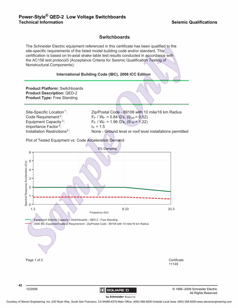
© 1995–2009 Schneider ElectricAll Rights Reserved
Power-Style® QED-2 Low Voltage SwitchboardsTechnical Information Seismic Qualifications
4212/2009
Page 1 of 2 Certificate11149
Switchboards
The Schneider Electric equipment referenced in this certificate has been qualified to thesite-specific requirements of the listed model building code and/or standard. Thiscertification is based on tri-axial shake table test results conducted in accordance withthe AC156 test protocol3 (Acceptance Criteria for Seismic Qualification Testing ofNonstructural Components):
International Building Code (IBC), 2006 ICC Edition
Product Platform: SwitchboardsProduct Description: QED-2Product Type: Free Standing
Site-Specific Location :1 Zip/Postal Code - 89108 with 10 mile/16 km RadiusCode Requirement :2 F / W = 0.84 G's, (S = 0.52)Equipment Capacity :3
Importance Factor :4 I = 1.5Installation Restrictions :5 None - Ground level or roof level installations permitted
Plot of Tested Equipment vs. Code Acceleration Demand
5% Damping
Equipment Seismic Capacity - Switchboards - QED-2 - Free Standing2006 IBC Equipment Lateral Requirement - Zip/Postal Code - 89108 with 10 mile/16 km Radius
1.3 8.33 33.3Frequency (Hz)
0
1
2
3
4
5
6
Spe
ctra
l Res
pons
e A
ccel
erat
ion
(G's
)
P P DS
F / W = 1.96 G's, (S = 1.22)P P DS
P
Equipm ismicment Late
acity
Acc
5
on Dema
amping
Grou
De
e - 89108 withG's, (S = 0.
's, (S = 1
con Te
hng of
Equipme y - teral
mic C
Acce
5%
Groun
emanon
h 0.5
= 1
89(S
accTes
d tos
nces
E eismic Capacpment Lat
ion D
Damping
deGG's,
wit0
=
onth
ng of
Courtesy of Steven Engineering, Inc.-230 Ryan Way, South San Francisco, CA 94080-6370-Main Office: (650) 588-9200-Outside Local Area: (800) 258-9200-www.stevenengineering.com

Power-Style® QED-2 Low Voltage SwitchboardsSeismic Qualifications Technical Information
4312/2009© 1995–2009 Schneider Electric
All Rights Reserved
Page 2 of 2 Certificate11149
Switchboards
Compliance Notes
1. The site-specific location is defined as the final geographic location of equipment installation. Theseismic certification contained herein is valid for equipment installations located within thefollowing US region, state(s), or geographic coordinate: Zip/Postal Code - 89108 With 10 mile/16km Radius - Lat/Lon (36.211690,-115.220219). For the purpose of this document, the location isdefined as a circle centered at the latitude and longitude with the radius indicated.
2. By reference to ASCE 7-05, the 2006 IBC specifies seismic demand requirements for nonstructuralequipment in terms of a lateral force coefficient, FP / WP. The lateral force coefficient is defined interms of a site-specific ground spectral acceleration factor, SDS, which varies with geographiclocation and is adjusted for geotechnical site class effects per Chapter 11 of ASCE 7-05. The lateralforce coefficient is also defined in terms of the component amplification factor, a p, and a maximumvalue of two-and-a-half (ap = 2.5) is assumed. The maximum SDS value for Site Class D (codedefault site class) was determined using the USGS ground motion data, as required by ASCE 7-05,for the specified location(s) and is used as the 2006 IBC requirement for this seismic certification.
3. Equipment capacity was determined from tri-axial seismic shake table test results as defined in theInternational Code Council (ICC) Acceptance Criteria for Seismic Qualification by Shake-Testing ofNonstructural Components and Systems (AC156). Per Section 13.2.5 of ASCE 7-05, seismicqualification by testing based upon a nationally recognized testing standard procedure, such as ICCES AC156, shall be deemed to satisfy the design and evaluation requirements provided that thetested seismic capacity equals or exceeds the seismic demands determined in accordance withSections 13.3.1 and 13.2.2.
4. An equipment importance factor of 1.5 (I P = 1.5) indicates that equipment functionality wasverified before and after seismic simulation testing. This importance factor is indicative of criticalfacilities where maximizing the probability of post event functionality is a priority.
5. Seismic qualification of nonstructural components by Schneider Electric is just one link in the totalchain of responsibility required to maximize the probability that the equipment will be intact andfunctional after a seismic event. During a seismic event the equipment must be able to transfer theloads that are created through the mounting pad and anchorage to the load-bearing path of thebuilding structural system. Anchorage of equipment to the primary building structure is required tovalidate this seismic certification. The structural engineer or design engineer of record isresponsible for detailing the equipment anchorage requirements for the given installation. Theinstaller and manufacturers of the anchorage system are responsible for assuring that themounting requirements are met. Schneider Electric is not responsible for the specification andperformance of anchorage systems.
This document is typical of the seismic certifications available for the referenced productand standards. Actual performance may be configuration dependent. Certificates mustbe signed and numbered to be valid for construction. Contact your local SchneiderElectric representative for additional information or to obtain actual seismic certificates.
stansi
ec p
tAnumbe
tative
typicaal per
ed
mentnchora
t
ng thturerss re me
syste
Anccation
equipmehe an
o mt Duri
moue of eq
strucanchor
age
al compmaximize
seg
5 (I P
ation tof po
ents b
s
) indicatesng. This
n aseism
t amplificatim SDS val
un n dataC requirement fo
c sha teSeismic if
tion 13.2.5
vaer 11 o
factor Site
req
remecoeffici with e
SCE 7
ate89108
ment,ed.
or nonis d
hin thWith 10 mile/1
cation is
cturd id
n
dostand
e signedctr represe
nt i typical os. Actual perf
numberede
g. Anchfication. h
ng the equipmeactur s o the nc
ments are met Schanchorag system
f th
ural compoto maximi e t
nt. Durin a seihe ounting
age f equstructu
anchoragageer E
h
f 1 5 P =ati te
y o post e
nen bpr
gn anseismic
5) ndicatesng s im
event
per Chant amplificatio
xim aluou a,BC or
mic esS ificctio 5 o
sting st
uiremenrce coefficien
h varies w h geter of ASC 7
factor, afor ite
requ
pmcated
- 89108cument t
ate
for nonsis de
ation. Thi the
With 1 mile/16ocatio is
ucturaed in
at
Ele ntati
mu SD
n onrequiremen
hak tmic ali
3 2 5
e
n
h
Courtesy of Steven Engineering, Inc.-230 Ryan Way, South San Francisco, CA 94080-6370-Main Office: (650) 588-9200-Outside Local Area: (800) 258-9200-www.stevenengineering.com
© 1995–2009 Schneider ElectricAll Rights Reserved
Power-Style® QED-2 Low Voltage SwitchboardsTechnical Information Specifications
4412/2009
Specifications
General
Furnish and install the switchboard(s) as herein specified and shown on the associated electrical drawings. The switchboard(s) shall meet Underwriters Laboratories (UL) requirements and be furnished with a UL service entrance label.
Structures
The switchboard shall be enclosed, dead front, free standing, front and rear aligned with front and rear accessibility. The switchboard shall be NEMA Type (1 General Purpose) (3R Non-Walk-in Outdoor). The framework shall be of UL gauge steel secured together to support all cover plates, bussing, and component devices during shipment and installation. Formed removable closure plates shall be used on the front, rear, and sides. All closure plates are to be single tool, screw removable. Ventilation shall be provided when required. Each section shall include a single-piece removable top plate.
Finish
All painted parts shall be pretreated and provided with a corrosion-resistant, UL Listed acrylic baked paint finish. The paint color shall be ANSI #49 medium light gray per ANSI standard Z55.1-1967.
NEMA Type 3R enclosures shall be treated with the same process except that all exterior parts shall be of galvannealed steel. All exterior hardware on NEMA Type 3R enclosures shall be zinc-plated steel.
Ability to Withstand a Fault
The entire switchboard shall be suitable for operation at the specified available fault current. The switchboard shall be labeled to indicate the maximum available fault current rating, taking into account the structure, bussing, switchboard main disconnect(s), and switchboard branch circuit devices. The short circuit current rating of the switchboard(s) shall not be less than _____ rms symmetrical amperes. The switchboard branch circuit devices short circuit current rating shall be fully rated or determined by UL labeled series connected ratings.
Bussing
The switchboard through bus shall be (tin-plated aluminum) (tin-plated copper) (silver-plated copper). The switchboard bussing shall be of sufficient cross-sectional area to meet UL Standard 891 for temperature rise. The through bus shall have a maximum ampacity of (1,200) (1,600) (2,000) (2,500) (3,000) (4,000) (5,000) A and extend the full length of the switchboard. The through bus shall be 100% rated. Provisions shall be provided for future splicing of additional sections from either end. The neutral bus shall be 100% rated.
The switchboard distribution section bus shall be of the same material as the through bus and shall be rated (1,200) (1,600) (2,000) (3,000) A. The distribution section neutral plate shall be of copper provided with Cu/Al lugs for the devices installed and future specified devices. The ground bus shall be sized per UL Standard 891 and be of the same material as the through bus.
Utility Metering Compartments
The switchboard utility metering compartment shall be located in the service entrance section of the switchboard and connected for (hot) (cold) sequence metering. The utility metering compartment shall be (barriered) (unbarriered) and covered with a (single hinged door) (double hinged door) with sealing provisions.
Courtesy of Steven Engineering, Inc.-230 Ryan Way, South San Francisco, CA 94080-6370-Main Office: (650) 588-9200-Outside Local Area: (800) 258-9200-www.stevenengineering.com
Power-Style® QED-2 Low Voltage SwitchboardsSpecifications Technical Information
4512/2009© 1995–2009 Schneider Electric
All Rights Reserved
Main Disconnect Devices
The main disconnect device(s) shall be a (molded case circuit breaker) (solid-state trip, molded case circuit breaker) (fused bolted pressure switch). With the main device, (ground fault protection) (with zone interlocking) (undervoltage trip) (phase failure protection) (capacitor trip) (alarm switch) (auxiliary switches) (long time, short time) (long time, short time, instantaneous) shall be provided. Fuses for the bolted pressure switch are to be supplied by the (manufacturer) (user). A PowerLogic (power meter) (circuit monitor) (ION meter) with the appropriate transformers shall be provided, as required.
Group Mounted Branch Devices
The switchboard group-mounted (fusible) (circuit breaker) branch devices are to be front accessible and front connectable. The (fusible) (circuit breaker) connections to the distribution panel bussing shall be of a “blow-on” design such that the connections grip the bus bars firmly under high fault conditions.
Individually Mounted Circuit Breakers
Individually mounted branch circuit breakers shall be of the molded case type and be positioned vertically with the operating handles extending through the hinged front cover plates of the section. Each circuit breaker shall be individually fed by connectors from the main bus of the switchboard.
Surge Protective Device (SPD)
• Listed and Component Recognized in accordance with UL 1449, 3rd edition, to include Section 37.3 highest fault current category. SPD devices shall be UL 1283 listed.
• Provide surge current diversion paths for all modes of protection—L-N, L-G, and N-G—in Wye systems.
• Modular in design. Each mode, including N-G, shall be fused with a 200 kAIR, UL-classified surge-rated fuse and incorporate a thermal cutout device.
• Provide audible diagnostic monitoring by way of audible alarm. Alarm shall activate upon a fault condition. Provide push-to-test switch, and alarm on/off switch to silence alarm.
• If a dedicated breaker for the SPD is not provided, the SPD shall include a UL-classified disconnect switch.
• Meet or exceed the following criteria:
— Minimum surge current capability (single pulse rated) per phase: (480 kA) (320 kA) (240 kA) (200 kA) (160 kA) (120 kA) (100 kA).
— UL 1449 suppression voltage rating, voltage L-N, L-G, N-G: (208Y/120 V; 400 V) (480Y/277 V; 600 V).
• EMI/RFI Filtering: up to -30dB 100 kHz with insertion ratio of 50:1 using MIL-STD-220A methodology.
• Provide with one set of NO/NC dry contacts.
• Accessories:
— Six-digit transient-counter set to total transient surges that deviate from the sine-wave envelope by more than 125 V.
Shipping Splits
Switchboards shall be separated into shipping blocks. Each switchboard section shall be capable of being handled individually with the use of removable lifting bars (where practical) or rollers, and shall be clearly labeled with proper handling procedures.
Courtesy of Steven Engineering, Inc.-230 Ryan Way, South San Francisco, CA 94080-6370-Main Office: (650) 588-9200-Outside Local Area: (800) 258-9200-www.stevenengineering.com
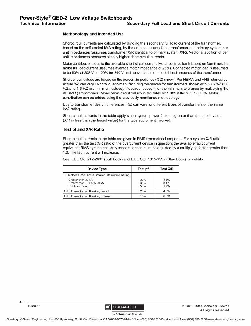
© 1995–2009 Schneider ElectricAll Rights Reserved
Power-Style® QED-2 Low Voltage SwitchboardsTechnical Information Secondary Full Load and Short Circuit Currents
4612/2009
Methodology and Intended Use
Short-circuit currents are calculated by dividing the secondary full load current of the transformer, based on the self-cooled kVA rating, by the arithmetic sum of the transformer and primary system per unit impedances (assumes transformer X/R identical to primary system X/R). Vectorial addition of per unit impedances produces slightly higher short-circuit currents.
Motor contribution adds to the available short-circuit current. Motor contribution is based on four times the motor full load current (assumes average motor impedance of 25%). Connected motor load is assumed to be 50% at 208 V or 100% for 240 V and above based on the full load amperes of the transformer.
Short-circuit values are based on the percent impedance (%Z) shown. Per NEMA and ANSI standards, actual %Z can vary +/-7.5% due to manufacturing tolerances for transformers shown with 5.75 %Z (2.0 %Z and 4.5 %Z are minimum values). If desired, account for the minimum tolerance by multiplying the XFRMR (Transformer) Alone short-circuit values in the table by 1.081 if the %Z is 5.75%. Motor contribution can be added using the previously mentioned methodology.
Due to transformer design differences, %Z can vary for different types of transformers of the same kVA rating.
Short-circuit currents in the table apply when system power factor is greater than the tested value (X/R is less than the tested value) for the type equipment involved.
Test pf and X/R Ratio
Short-circuit currents in the table are given in RMS symmetrical amperes. For a system X/R ratio greater than the test X/R ratio of the overcurrent device in question, the available fault current equivalent RMS symmetrical duty for comparison must be adjusted by a multiplying factor greater than 1.0. The fault current will increase.
See IEEE Std. 242-2001 (Buff Book) and IEEE Std. 1015-1997 (Blue Book) for details.
Device Type Test pf Test X/R
UL Molded Case Circuit Breaker Interrupting Rating
Greater than 20 kAGreater than 10 kA to 20 kA10 kA and less
20%30%50%
4.8993.1791.732
ANSI Power Circuit Breaker, Fused 20% 4.899
ANSI Power Circuit Breaker, Unfused 15% 6.591
Courtesy of Steven Engineering, Inc.-230 Ryan Way, South San Francisco, CA 94080-6370-Main Office: (650) 588-9200-Outside Local Area: (800) 258-9200-www.stevenengineering.com
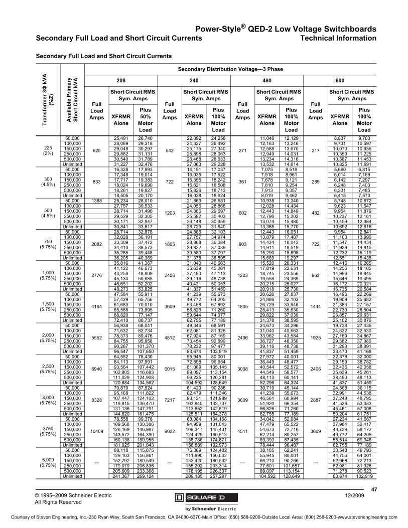
Power-Style® QED-2 Low Voltage SwitchboardsSecondary Full Load and Short Circuit Currents Technical Information
4712/2009© 1995–2009 Schneider Electric
All Rights Reserved
Secondary Full Load and Short Circuit Currents
Tra
nsf
orm
er
3Φ
kV
A
(%Z
)
Ava
ilab
le P
rim
ary
S
ho
rt C
ircu
it k
VA
Secondary Distribution Voltage—3 Phase
208 240 480 600
Full Load Amps
Short Circuit RMS Sym. Amps
Full Load Amps
Short Circuit RMS Sym. Amps
Full Load Amps
Short Circuit RMS Sym. Amps
Full Load Amps
Short Circuit RMS Sym. Amps
XFRMR Alone
Plus 50%
Motor Load
XFRMR Alone
Plus 100% Motor Load
XFRMR Alone
Plus 100% Motor Load
XFRMR Alone
Plus 100% Motor Load
225(2%)
50,000
625
25,491 26,740
542
22,092 24,258
271
11,046 12,129
217
8,837 9,703100,000 28,069 29,318 24,327 26,492 12,163 13,246 9,731 10,597150,000 29,048 30,297 25,175 27,340 12,588 13,670 10,070 10,936250,000 29,882 31,131 25,898 28,063 12,949 14,031 10,359 11,225500,000 30,540 31,789 26,468 28,633 13,234 14,316 10,587 11,453Unlimited 31,227 32,476 27,063 29,228 13,532 14,614 10,825 11,691
300(4.5%)
50,000
833
16,328 17,993
722
14,151 17,037
361
7,075 8,519
289
5,660 6,815100,000 17,348 19,014 15,035 17,922 7,518 8,961 6,014 7,169150,000 17,717 19,383 15,355 18,242 7,678 9,121 6,142 7,297250,000 18,024 19,690 15,621 18,508 7,810 9,254 6,248 7,403500,000 18,261 19,927 15,826 18,713 7,913 9,357 6,331 7,485Unlimited 18,505 20,170 16,038 18,924 8,019 9,462 6,415 7,570
500(4.5%)
50,000 1388 25,234 28,010
1203
21,869 26,681
602
10,935 13,340
482
8,748 10,672100,000 27,757 30,533 24,056 28,868 12,028 14,434 9,623 11,547150,000 28,714 31,490 24,886 29,697 12,443 14,849 9,954 11,879250,000 29,529 32,305 25,592 30,403 12,796 15,202 10,237 12,161500,000 30,171 32,947 26,148 30,959 13,074 15,480 10,459 12,384Unlimited 30,841 33,617 26,729 31,540 13,365 15,770 10,692 12,616
750(5.75%)
50,000
2082
28,714 32,878
1805
24,886 32,103
903
12,443 16,051
722
9,954 12,841100,000 32,028 36,191 27,757 34,974 13,879 17,487 11,103 13,990150,000 33,309 37,472 28,868 36,084 14,434 18,042 11,547 14,434250,000 34,410 38,573 29,822 37,039 14,911 18,519 11,929 14,815500,000 35,285 39,448 30,580 37,797 15,290 18,898 12,232 15,119Unlimited 36,205 40,369 31,378 38,595 15,689 19,297 12,551 15,438
1,000(5.75%)
50,000
2776
35,816 41,367
2406
31,040 40,663
1203
15,520 20,331
963
12,416 16,265100,000 41,122 46,673 35,639 45,261 17,819 22,631 14,256 18,105150,000 43,258 48,809 37,490 47,113 18,745 23,556 14,996 18,845250,000 45,134 50,685 39,116 48,738 19,558 24,369 15,646 19,495500,000 46,651 52,202 40,431 50,053 20,215 25,027 16,172 20,021Unlimited 48,273 53,825 41,837 51,459 20,918 25,730 16,735 20,584
1,500(5.75%)
50,000
4164
47,584 55,911
3609
41,239 55,673
1805
20,620 27,837
1444
16,496 22,269100,000 57,429 65,756 49,772 64,205 24,886 32,103 19,909 25,682150,000 61,683 70,010 53,458 67,892 26,729 33,946 21,383 27,157250,000 65,568 73,895 56,826 71,260 28,413 35,630 22,730 28,504500,000 68,820 77,147 59,644 74,077 29,822 37,039 23,857 29,631Unlimited 72,410 80,737 62,755 77,189 31,378 38,595 25,102 30,876
2,000(5.75%)
50,000
5552
56,938 68,041
4812
49,346 68,591
2406
24,673 34,296
1925
19,738 27,436100,000 71,632 82,734 62,081 81,326 31,040 40,663 24,832 32,530150,000 78,373 89,476 67,924 87,169 33,962 43,584 27,169 34,867250,000 84,755 95,858 73,454 92,699 36,727 46,350 29,382 37,080500,000 90,267 101,370 78,232 97,477 39,116 48,738 31,293 38,991Unlimited 96,547 107,650 83,674 102,919 41,837 51,459 33,470 41,168
2,500(5.75%)
50,000
6940
64,552 78,430
6015
55,945 80,001
3008
27,972 40,001
2406
22,378 32,000100,000 84,113 97,991 72,898 96,954 36,449 48,477 29,159 38,782150,000 93,564 107,442 81,089 105,145 40,544 52,572 32,435 42,058250,000 102,805 116,683 89,097 113,154 44,549 56,577 35,639 45,261500,000 111,029 124,908 96,225 120,281 48,113 60,141 38,490 48,113Unlimited 120,684 134,562 104,592 128,649 52,296 64,324 41,837 51,459
3,000(5.75%)
50,000
8328
70,870 87,524
7217
61,420 90,288
3609
30,710 45,144
2887
24,568 36,115100,000 95,168 111,822 82,479 111,346 41,239 55,673 32,991 44,538150,000 107,447 124,102 93,121 121,989 46,561 60,994 37,248 48,795250,000 119,815 136,470 103,840 132,707 51,920 66,354 41,536 53,083500,000 131,136 147,791 113,652 142,519 56,826 71,260 45,461 57,008Unlimited 144,820 161,475 125,511 154,378 62,755 77,189 50,204 61,751
3750(5.75%)
50,000
10409
78,558 99,376
9022
68,084 104,168
4511
34,042 52,084
3609
27,234 41,667100,000 109,568 130,386 94,959 131,043 47,479 65,522 37,984 52,417150,000 126,169 146,987 109,347 145,431 54,673 72,716 43,739 58,172250,000 143,572 164,390 124,429 160,513 62,214 80,257 49,772 64,205500,000 160,138 180,956 138,786 174,871 69,393 87,435 55,514 69,948Unlimited 181,025 201,843 156,889 192,973 78,444 96,487 62,755 77,189
5,000(5.75%)
50,000
—
88,118 115,875
—
76,369 124,482
—
38,185 62,241
—
30,548 49,793100,000 129,103 156,861 111,890 160,002 55,945 80,001 44,756 64,001150,000 152,792 180,549 132,420 180,532 66,210 90,266 52,968 72,213250,000 179,079 206,836 155,202 203,314 77,601 101,657 62,081 81,326500,000 205,609 233,366 178,195 226,307 89,097 113,154 71,278 90,523Unlimited 241,367 269,124 209,185 257,297 104,592 128,649 83,674 102,919
Courtesy of Steven Engineering, Inc.-230 Ryan Way, South San Francisco, CA 94080-6370-Main Office: (650) 588-9200-Outside Local Area: (800) 258-9200-www.stevenengineering.com
2742CT9501R12/09 © 1995–2009 Schneider Electric All Rights Reserved Replaces 2742CT9501 12/1995
12/2009
Schneider Electric1010 Airpark Center DriveNashville, TN 37217 USA1-888-Square D1-888-778-2733www.schneider-electric.us
About Schneider Electric
As a global specialist in energy management with operations in more than 100 countries, Schneider Electric offers integrated solutions across multiple market segments, including leadership positions in energy and infrastructure, industrial processes, building automation, and data centers/networks, as well as a broad presence in residential applications. Focused on making energy safe, reliable, and efficient, the company's 120,000 employees achieved sales of more than 25.6 billion US dollars (17.3 billion euros) in 2007, through an active commitment to help individuals and organizations “Make the most of their energy.”
Courtesy of Steven Engineering, Inc.-230 Ryan Way, South San Francisco, CA 94080-6370-Main Office: (650) 588-9200-Outside Local Area: (800) 258-9200-www.stevenengineering.com