switchboards and distribution system - epsmg.jkr.gov.myepsmg.jkr.gov.my/images/d/d1/chap6.pdf ·...
TRANSCRIPT
CKE/PT/Chapter6/004.0908
Panduan Teknik Edisi Ke-4 2008 Cawangan Kejuruteraan Elektrik Pg 1 of 9
Switchboards and DistributionSystem
1.0 Type of switchboards
a) Self-contained, floor mounted, flush fronted, metal clad cubicle typesuitable for front and rear access. It shall be designed to withstand faultcondition of not less than 50kA at 415 V for 1 second as defined in IEC60439-1 and shall be of Form 2b or otherwise specified by DE.
b) Front access switchboardsc) Wall mounted switchboardsd) Pedestal type (obsolete)
2.0 Type of incoming switch gear
a) Air circuit breaker is normally used as incoming switchgear. It shall becertified for minimum rupturing capacity of 50kA at 415 for 1 s as defined inIEC 60947 or otherwise specified have breaking capacity of 31MVA at 415V with a short time rating of 1 second.
b) MCCB
3.0 Number of TNB incomers
Sometimes two transformers are supplied by TNB. This may happen when:-
(i) a single transformer is insufficient to cater for the total load of theinstallation, or
(ii) a more secured supply system for the installation is required.
Whatever the cause may be, the main switchboard must be designed to receivethe two incoming feeders from the separate transformer. In this case it is normalpractice to incorporate a 4 pole coupler between the two sections of main busbarsfed by the two transformers to provide further flexibility in the supply system. Thecoupler must at least be mechanically interlocked with the other two incomingCircuit Breaker (CB) so that the coupler can only be closed if either one of the twoincoming CBs is opened in order to satisfy TNB’s requirement.
4.0 Outgoing switch gears
Type of outgoing switch gears are:
a) ACBb) MCCBc) Switch fuse
CKE/PT/Chapter6/004.0908
Panduan Teknik Edisi Ke-4 2008 Cawangan Kejuruteraan Elektrik Pg 2 of 9
d) Fuse switch
The selection of type switchgears above is depends to current capacity and otherrequirement been concerned. If the MCCB had been used, the minimuminterrupting capacity of the breaker must be specified.
5.0 Type of supply to switchboards
a) Normal supply from TNBb) Essential supply from generator set and Uninterruptible Power Supply
(UPS)
For more details refer to ‘Nota Tambahan Kepada Panduan Teknik’, Chapter 2.
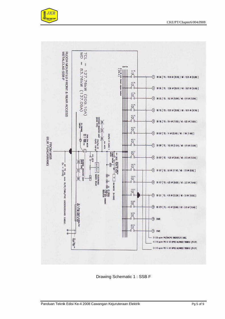
6.0 Drawings and Sub Switch Board (SSB) Design
Refer to the schematic drawing 1: SSB F;
1 There are no rules of uniformity for SSB downstream output. But for futureusage (expansion), the SSB require spare way. The spare way ofdownstream is decided by the DE (with referring to the technical aspect).
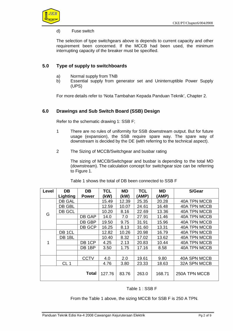
2 The Sizing of MCCB/Switchgear and busbar rating
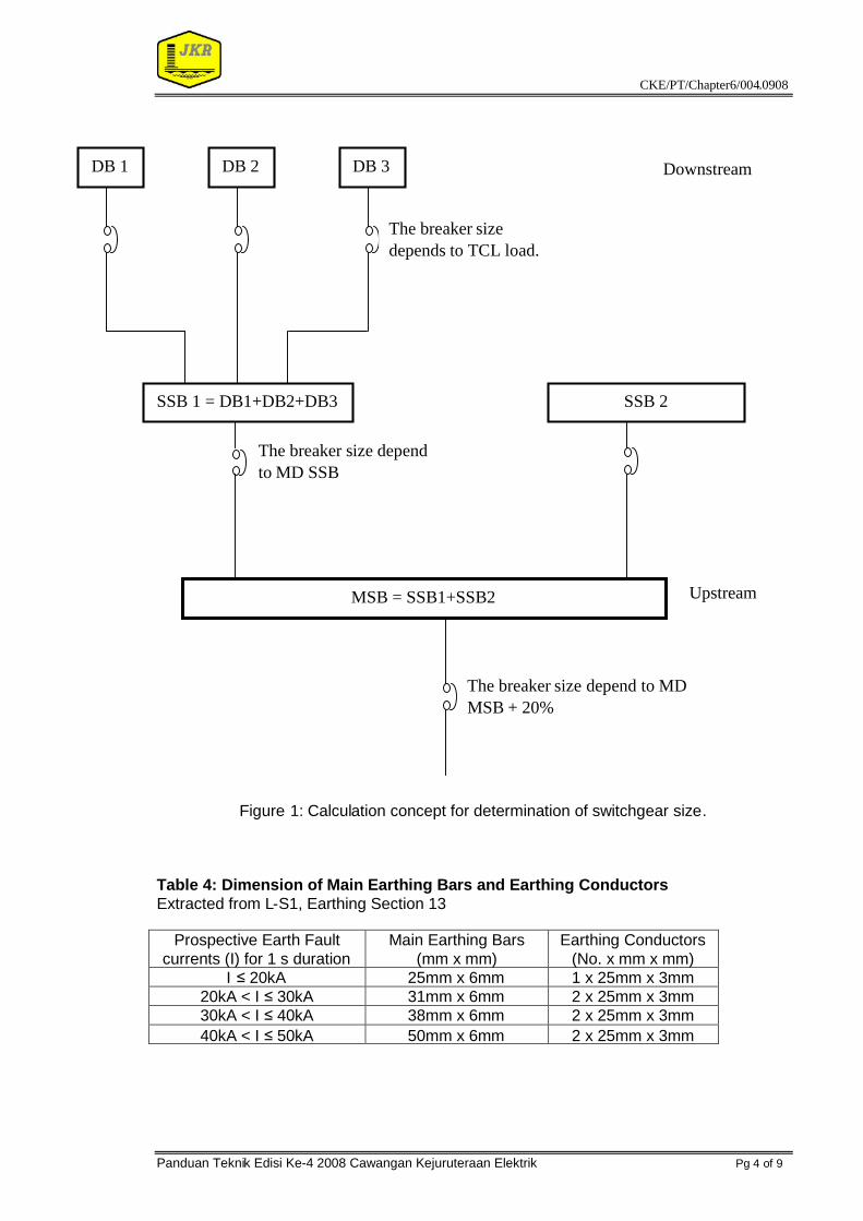
The sizing of MCCB/Switchgear and busbar is depending to the total MD(downstream). The calculation concept for switchgear size can be referringto Figure 1.
Table 1 shows the total of DB been connected to SSB F
Level DBLighting
DBPower
TCL(kW)
MD(kW)
TCL(AMP)
MD(AMP)
S/Gear
DB GAL 15.49 12.39 25.35 20.28 40A TPN MCCBDB GBL 12.59 10.07 24.61 16.48 40A TPN MCCBDB GCL 10.20 8.16 22.69 13.36 40A TPN MCCB
DB GAP 14.0 7.0 27.91 11.46 40A TPN MCCBDB GBP 19.50 9.75 31.91 15.96 40A TPN MCCB
G
DB GCP 16.25 8.13 31.60 13.31 40A TPN MCCBDB 1CL 12.82 10.26 20.98 16.79 40A TPN MCCBDB 1BL 10.40 8.32 17.02 13.62 40A TPN MCCB
DB 1CP 4.25 2.13 20.83 10.44 40A TPN MCCBDB 1BP 3.50 1.75 17.16 8.58 40A TPN MCCB
1
CCTV 4.0 2.0 19.61 9.80 40A SPN MCCBCL 1 4.76 3.80 23.33 18.63 32A SPN MCCB
Total 127.76 83.76 263.0 168.71 250A TPN MCCB
Table 1 : SSB F
From the Table 1 above, the sizing MCCB for SSB F is 250 A TPN.
CKE/PT/Chapter6/004.0908
Panduan Teknik Edisi Ke-4 2008 Cawangan Kejuruteraan Elektrik Pg 3 of 9
3 The busbar rating must be not less than incoming switchgear size. Thebusbar must be tinned copper type.
4 Chosen of leakage protection relay :
Use ELR with Zct : 20A 3 phase ≤x ≤250A 3 phaseUse EF with CT (min 2 OC/1EF) : x > 250A
Installation of protection relay at:
i. For isolators/mechanical loads: at upstream MCCBii. For other type loads within same building: at downstream MCCBiii. Load via underground cable: at both upstream & downstream
MCCB
5 The SPD must be type C.
6 Determination of cable size from SSB to DB.
Refer to the chapter 7, ’Reticulation Cable Size and Voltage DropCalculation’.
7 Facility of measuring and monitoring devices
The facility of measuring and monitoring devices at SSB is depending tothe incoming switch gear rating and the usage of the panel. The itemisedneed to install is:a) incoming phase indicating light – LED type c/w fuseb) voltmeterc) ammeterd) kilowatt hour metere) items b, c and d may be replaced with a digital power meter to
connect to electrical building automation system (SCADA) enablingcollecting data and may be used for measurement of efficiency andimprovement etc.
8 Switchboard Earthing busbar - indicate the bar, its size to be referred totable 4 L-S1, according to the fault current rating.
9 Name of SSB legend need to be refer where the panel be locate.
CKE/PT/Chapter6/004.0908
Panduan Teknik Edisi Ke-4 2008 Cawangan Kejuruteraan Elektrik Pg 4 of 9
Figure 1: Calculation concept for determination of switchgear size.
Table 4: Dimension of Main Earthing Bars and Earthing ConductorsExtracted from L-S1, Earthing Section 13
Prospective Earth Faultcurrents (I) for 1 s duration
Main Earthing Bars(mm x mm)
Earthing Conductors(No. x mm x mm)
I ≤20kA 25mm x 6mm 1 x 25mm x 3mm20kA < I ≤30kA 31mm x 6mm 2 x 25mm x 3mm30kA < I ≤40kA 38mm x 6mm 2 x 25mm x 3mm40kA < I ≤50kA 50mm x 6mm 2 x 25mm x 3mm
MSB = SSB1+SSB2
SSB 1 = DB1+DB2+DB3 SSB 2
DB 1 DB 2 DB 3 Downstream
The breaker sizedepends to TCL load.
The breaker size dependto MD SSB
The breaker size depend to MDMSB + 20%
Upstream
CKE/PT/Chapter6/004.0908
Panduan Teknik Edisi Ke-4 2008 Cawangan Kejuruteraan Elektrik Pg 5 of 9
Drawing Schematic 1 : SSB F
CKE/PT/Chapter6/004.0908
Panduan Teknik Edisi Ke-4 2008 Cawangan Kejuruteraan Elektrik Pg 6 of 9
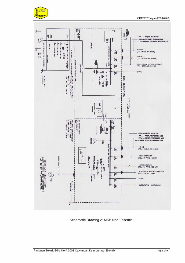
6.0 Design and Schematic Drawing For Main Switch Board (MSB)
Refer to Schematic Drawing 2:
1 In MSB schematic drawing, need to provide the spare outgoing. The sizingspare outgoing is depending to DE (base on experience, complex of theproject and future expansion of the complex).
2 Determination of MCCB/switch gear and busbar sizing
The determination of MCCB/switch gear size for MSB is depending to totalmaximum demand (MSB) + 20 %. Refer to Table 2.
The Table 2 shows the total load had been connected to MSB NonEssential.
No MSB Non E TCL(kW)
MD(kW)
TCL(AMP)
MD(AMP)
MCCBRating
1 SSB G 127.76 83.76 263.0 168.71 250A2 Feeder Pillar 5.91 4.73 9.67 7.74 40A3 MSB Essential 420.00 409.00 687.40 669.39 800A4 MSB FAMA
(Existing)79.80 63.84 130.61 104.48 150A
5 STP (SaverageTreatment Plant)
10.00 10.00 16.37 16.37 40A
Total 643.47 571.33 1107.05 966.69 1200A TPN
Table 2 : MSB Non Essential
MD + 20% = 966.69 + 193.34= 1160.02 A
Base on calculation above, where the maximum Demand + 20 %( future)is 1160.02 A, the sizing of switch gear for MSB Non Essential is 1200 A 4Pole.
The sizing of busbar panel must be same rating as incoming switch gear.The busbar must be tinned copper type.
3 Chosen of Protection relay.
Use ELR with Zct : 20A 3 phase ≤x ≤250A 3 phaseUse EF with CT (min 2 OC/1EF) : x > 250A
Installation of protection relay at:
i. For isolators/mechanical loads: at upstream MCCBii. For other type loads within same building: at downstream MCCBiii. Load via underground cable: at both upstream & downstream MCCB
CKE/PT/Chapter6/004.0908
Panduan Teknik Edisi Ke-4 2008 Cawangan Kejuruteraan Elektrik Pg 7 of 9
4 The SPD must be type C.
5 Determination of cable size from SSB to DB.
Refer to the chapter 7, ’Reticulation Cable Size and Voltage DropCalculation’.
6 Facility of measuring and monitoring devices
The facility of measuring and monitoring devices at MSB is depending tothe incoming switch gear rating and the usage of the switchboards. Theitemised need to install is:
a) incoming phase indicating light – LED type c/w fuseb) busbar phase indicating light – LED type c/w fuseb) voltmeterc) ammeterd) kilowatt hour metere) items b, c and d may be replaced with a digital power meter to
connect to electrical building automation system (SCADA) enablingcollecting data and may be used for measurement of efficiency andimprovement etc.
7 Switchboard Earthing busbar - indicate the bar, its size to be referred totable 4 L-S1, according to the fault current rating.
8 Name of MSB legend need to refer where the panel be locate as.a) MSB NE (Non Essential)
Supply direct from TNBb) MSB E (Essential)
Supply from Generator Setc) MSB Mechanical, dsb.
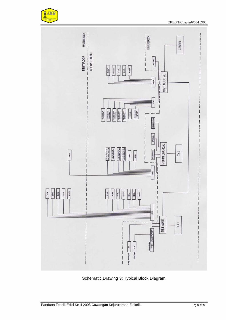
9 Block diagram
Refer schematic drawing 3.
CKE/PT/Chapter6/004.0908
Panduan Teknik Edisi Ke-4 2008 Cawangan Kejuruteraan Elektrik Pg 8 of 9
Schematic Drawing 2: MSB Non Essential
CKE/PT/Chapter6/004.0908
Panduan Teknik Edisi Ke-4 2008 Cawangan Kejuruteraan Elektrik Pg 9 of 9
Schematic Drawing 3: Typical Block Diagram