electric switchboards 0-600 volts...electric switchboards 0 – 600 volts sb0001m volume 17 –...
TRANSCRIPT

ELECTRIC SWITCHBOARDS 0 – 600 VOLTS SB0001M
VOLUME 17 – ENGINERING & CONSTRUCTION STANDARD
SB0001M
ELECTRIC SWITCHBOARDS 0 – 600 VOLTS Drawn: Eng: Appr: Date: Revision: 6
JL MB DA 3/14 Page 1 of 28
ELECTRIC SWITCHBOARDS 0-600 VOLTS
1.0 INDEX
1.0 INDEX
2.0 SCOPE
3.0 GENERAL METERING REQUIREMENTS
4.0 SWITCHBOARD - GENERAL
5.0 SWITCHBOARD SERVICE SECTION
6.0 SERVICE ENTRANCE LOCATION
7.0 UNDERGROUND SERVICE PULL SECTION
8.0 METER SWITCH SEQUENCE
9.0 SERVICE TERMINATIONS
10.0 METER PANELS
11.0 METER SOCKETS
2.0 SCOPE
This Standard provides specific dimensions and details of service and meter equipment which is
assembled by the manufacturer in free-standing, self-supporting switchboard construction, and which is
not covered by the basic requirements in the “Electric Metering - General” Section, NVE Standard
GM0001M.
3.0 GENERAL METERING REQUIREMENTS
Important information pertaining to all metering installations is contained in GM0001M. This section
should be reviewed before proceeding with the purchase of equipment or installation of wiring.
4.0 SWITCHBOARDS - GENERAL
Prior to manufacturer, the customer shall submit 2 copies of the drawings of the proposed
switchboard, its location, and pad design to NVE. The address is:
NV Energy
Electric Metering Dept. (R90EM)
Team Leader
P.O. Box 10100
Reno, Nevada 89520-0400

ELECTRIC SWITCHBOARDS 0 – 600 VOLTS SB0001M
VOLUME 17 – ENGINERING & CONSTRUCTION STANDARD
SB0001M
ELECTRIC SWITCHBOARDS 0 – 600 VOLTS Drawn: Eng: Appr: Date: Revision: 6
JL MB DA 3/14 Page 2 of 28
Additionally, the customer shall consult NVE for specific information on the following:
a. Service voltage, current rating, and fault duty.
b. Meter panel requirements for applicable rate schedule
c. Service termination location
d. Switchboard and/or meter location(s)
e. Size and number of service conductors and conduits per phase.
f. The rating of the metering current transformers will not necessarily be the same as the current
rating of the service switch. Fault duty rating will exceed given fault duty.
All compartments containing unmetered conductors shall be sealable. When a raceway or conduit for
meter secondary wiring is necessary, such raceway or conduit shall be sealable.
Service entrance conductors must enter the metering transformer compartment from one end and exit
from the opposite end.
Service entrance transformers, and test switches will be furnished and installed by NVE. Secondary
wiring from metering transformers to meters will be installed by NVE. Any required conduits or
raceways shall be furnished and installed by the customer.
Where meters remote from the switchboard location are required, meter secondary wiring from current
transformers to meter sockets will not exceed 50 feet. Conduit for secondary wiring will be supplied by
the customer. Minimum size of the conduit will be 1-1/2". There will be no more than two (2)
sweeping 90° elbows in one run. L.B.’s or similar fittings will not be allowed. Contractor shall
contact NVE before installing secondary wire conduit. Provisions for safety sockets for these remote
meters should be as described on NVE Standards Drawing, CM0001M.
When self-contained meter sockets are installed in switchboards, they are to be wired by the switchboard
manufacturer.
Manufactured freestanding outdoor switchboards shall be installed in accordance with NEC, Article
408. Freestanding switchboards shall be securely fastened to a concrete pad to prevent possible
movement of the switchboard. The concrete pad provided shall be of sufficient size to extend 6" beyond
the sides and back of the switchboard with a 36" working space extended in front. The 6" thick pad
shall be 6" x 6" wide mesh reinforced and have a 5/8" x 8' ground rod conveniently provided to facilitate
equipment grounding. The following example provides typical pad dimensions:

ELECTRIC SWITCHBOARDS 0 – 600 VOLTS SB0001M
VOLUME 17 – ENGINERING & CONSTRUCTION STANDARD
SB0001M
ELECTRIC SWITCHBOARDS 0 – 600 VOLTS Drawn: Eng: Appr: Date: Revision: 6
JL MB DA 3/14 Page 3 of 28
NOTES: 1. 45° chamfer all corners.
2. 8" subbase compacted to 90% of the relative density at optimum moisture content and graded level
to finish grade.
3. Refer to PE0009U for clearances and protection requirements.
4. Refer to CB0003U for cable and conduit selection.
5.0 SWITCHBOARD SERVICE SECTION
5.1 Standard Switchboard Service Section - General
A service section is defined as the section of a customer’s switchboard provided specifically for
terminating the service, and housing the metering transformers (if required), revenue meters, test
facilities, and service switch or breaker.
Taps may be taken from main service entrance conductors where more than one meter installation
is necessary:
a. When required on an overhead service, taps shall be made in a sealable compartment above
and separate from the current transformer compartment.
b. When required on an underground service, taps shall be made in the underground service
termination pull section or pull box, provided suitable approved terminations are made on bus
conductors and positioned so that incoming service entrance conductors and their connections
shall not encroach into NVE's pulling area nor interfere with NVE’s pull and termination of its
service conductors.
In cases where more than one meter is to be installed, there will ordinarily be a separate service
section for each meter installation and its associated service switch.
For services with self-contained meters (not using current transformers) it may be practicable to
put two or more meters and switches in the same service section.

ELECTRIC SWITCHBOARDS 0 – 600 VOLTS SB0001M
VOLUME 17 – ENGINERING & CONSTRUCTION STANDARD
SB0001M
ELECTRIC SWITCHBOARDS 0 – 600 VOLTS Drawn: Eng: Appr: Date: Revision: 6
JL MB DA 3/14 Page 4 of 28
When two or more switchboard service sections are supplied from one set of service conductors,
the supply conductors serving these switchboards shall be terminated ahead of and outside of the
metering transformer compartments in a separate sealable enclosure. The supply conductors are to
be arranged so they are readily accessible and may be worked upon without disturbing the
metering transformers and associated secondary wiring.
The general arrangement of a standard switchboard service section is shown on Page 10. The
standard section utilizes a hinged meter panel located in front of the metering transformer
compartment. Hinged meter panels must be sealable and easily removable with the hinges readily
interchangeable from the right or left side on the job site. Hinged panels approved for socket
meters are shown on Page 15. Hinged meter panels must have handles and open a minimum of
90° with meters and test switches mounted to permit safe and ready access to the instrument
transformers. When hinged panels are recessed, the section shall have additional width to meet
this requirement. A recessed panel requires utility approval as a specially engineered section.
Switchboards to be used outdoors shall be of weatherproof construction in accordance with NEC,
Article 408. Indoor switchboards used outdoors shall be enclosed in a permanent rain tight
enclosure. Plywood or wood enclosures are unacceptable.
5.2 Specially Engineered Service Section
Switchboard design which does not conform to the standard switchboard is considered specially
engineered, and includes installations:
a. Over 4,000 amperes
b. When the service breaker is too large for the standard service section
c. When multiple metering sections are used
d. When recessed meter panels are used
When a specially engineered service section is necessary, two drawings of the proposed section
shall be submitted to NVE (See Section 4.0 for address) for approval prior to manufacturer and
bidding. Such drawings shall indicate the contractor’s and the customer’s name and address.
The general arrangement of specially engineered switchboard service sections should follow, as
nearly as practicable, that of the Standard Section, and the following general requirements shall be
observed:
a. Socket meters used with current transformers shall normally be mounted on hinged panels.
Self-contained meters shall be mounted on hinged panels.
b. When a hinged meter panel is located behind a door, a clear space of at least 11 inches between
the meter panel and the door is required as well as 90° opening with meter and test switches in
place. If needed, additional section width shall be provided to meet the requirements.
c. A clear space in back of a meter panel shall be provided for the secondary wiring. For hinged
meter panels, the minimum dimensions between the meter panel and the nearest bus as shown
ELECTRIC SWITCHBOARDS 0 – 600 VOLTS SB0001M
VOLUME 17 – ENGINERING & CONSTRUCTION STANDARD
SB0001M
ELECTRIC SWITCHBOARDS 0 – 600 VOLTS Drawn: Eng: Appr: Date: Revision: 6
JL MB DA 3/14 Page 5 of 28
on Pages 17 through 22 are adequate to provide this clearance. For non-hinged meter panels, a
clear space of at least four inches to any barrier or obstruction shall be provided.
d. Minimum clearance between meters shall also be maintained as shown on Page 26.
e. A minimum of four inches of clear space is required directly below the bottom slot of the meter
test switch to permit safe connection of test leads.
f. Sockets installed on switchboards shall be as specified in NVE Standard GM0001M.
g. Not more than two meters shall be mounted on any removable meter panel.
h. Panels which provide access to instrument transformers or a service terminating pull section
shall not be larger than required for good accessibility. Removable panels shall be equipped
with lifting handles (rated for lifting 75#) mounted slightly above the panel center and shall
not be heavier than can be conveniently lifted by one man.
i. The front edge of the current transformer bus bars shall all be located in the same vertical
plane.
j. A removable bus section and suitable transformer support shall be provided to permit
installation of window-type current transformers for installations over 1,000 amperes.
k. Busses shall be adequately supported in the metering transformer compartment to withstand
the mechanical stresses of short circuit. The bus supports shall not interfere with installation or
removal of current transformers. Current transformers shall not be used to support the busses;
the busses shall be entirely self-supporting.
l. The busses and current transformer mountings shall be designed so that each of the current
transformers may be withdrawn from its mounting position directly through the access panel
without disturbing any other current transformer. When multi-leaf busses are used, the busses
shall be oriented so that they appear “edge wise” when viewed from the access panel.
m. The general arrangement and spacing of current transformers and the methods of mounting
current transformers shall conform in so far as practicable to the illustrations on Pages 17
through 22 (single leaf bus) and Pages 23 through 28 (multi-leaf bus).
n. For underground connection of specially engineered service sections, See Page 11.
o. Switchboard to be used outdoors shall be of weatherproof construction. Indoor switchboards
used outdoors shall be enclosed in a permanent rain tight enclosure. Plywood or wood
enclosures are unacceptable.

ELECTRIC SWITCHBOARDS 0 – 600 VOLTS SB0001M
VOLUME 17 – ENGINERING & CONSTRUCTION STANDARD
SB0001M
ELECTRIC SWITCHBOARDS 0 – 600 VOLTS Drawn: Eng: Appr: Date: Revision: 6
JL MB DA 3/14 Page 6 of 28
6.0 SERVICE ENTRANCE LOCATION
In the standard and specially engineered switchboard service section, all service or supply conductors
shall enter the service sections through one end and exit through the opposite end of the metering
transformer compartment. This stipulation applies to either overhead or underground service or if two
or more adjoining service sections are connected together. Direction of feed shall be vertical through
the metering compartment as shown on Page 10.
7.0 UNDERGROUND SERVICE PULL SECTION
When an underground service is to be installed by NVE, provisions for service termination shall be as
shown on Pages 8, 9, and 11.
Details of metering transformer compartments are shown on Pages 17 through 22.
Covers for metering transformer compartments shall be made of code gauge metal; if non-hinged panels
are used as covers, they shall be provided with lifting handles and be attached with sealable studs and
wing nuts or by other approved means.
Copper or EUSERC approved plated aluminum bus bar shall be used on both the line and load sides of
all current transformers. When aluminum bus is used, it must be stamped with approved plating process
designation at service termination and transformer mounting points.
When NVE requests links and supports for through-type current transformers, the bus and removable
links must be a compatible material.
The current transformers supplied by NVE for metering shall not be utilized for any other purpose.
The ends of the current transformers bus stubs shall be located so the current transformers can be
connected without removing adjacent panels.
The current transformer bus stub supports in the metering transformer compartment shall be sufficiently
rigid to maintain alignment of the bus.

ELECTRIC SWITCHBOARDS 0 – 600 VOLTS SB0001M
VOLUME 17 – ENGINERING & CONSTRUCTION STANDARD
SB0001M
ELECTRIC SWITCHBOARDS 0 – 600 VOLTS Drawn: Eng: Appr: Date: Revision: 6
JL MB DA 3/14 Page 7 of 28
8.0 METER SWITCH SEQUENCE
Meters and metering equipment shall normally be located ahead, or on the supply side of the customer’s
main switch fuse or circuit breaker. Exception to this normal sequence is permissible only when
required by electrical codes.
9.0 SERVICE TERMINATIONS
For overhead services, the customer shall furnish lugs and connect the cable to line and load sides of the
bus stubs in the current transformer compartment.
For underground services, NVE will terminate its service conductors on lug landings at the current
transformer bus stubs only when the service is a single-meter installation and the switchboard is rated
400 amperes or less.
NVE will terminate its service conductors on lug landings in the pull section, as shown in Figure 1 on
Page 8, when the service is multiple metering or the switchboard is rated above 400 amperes.
a. On switchboards rated 401-800 amperes, the customer shall install conductors from the service
termination lug landings to the line side of the current transformer compartment.
b. On switchboards rated above 800 amperes or with multiple meters, bus bars shall extend from
the service termination lug landing into the current transformer compartment.
10.0 METER PANELS
The hinged meter panels shown on Page 15 are designed to accommodate only transformer-rated socket
meters and are the only panels accepted by the electric metering operations.
The non-hinged meter panels shall not be used in front of a current transformer section.
Page 27 shows spacing’s for various combinations of multiple meters. Self-contained meters shall not
be mounted on hinged panels.
See Page 15 for dimensions of Service Section where only a Watt-hour meter is required. See Page 26
for dimensions of Service Section where multiple meters and separate recorder are required.

ELECTRIC SWITCHBOARDS 0 – 600 VOLTS SB0001M
VOLUME 17 – ENGINERING & CONSTRUCTION STANDARD
SB0001M
ELECTRIC SWITCHBOARDS 0 – 600 VOLTS Drawn: Eng: Appr: Date: Revision: 6
JL MB DA 3/14 Page 8 of 28
10.1 UNDERGROUND SERVICE TERMINATION Not more than two meters shall be mounted on any removable meter panel. Meter panels and filler
panels shall be equipped with stops to prevent inward swinging beyond the front surface of the
switchboard.
NOTES: 1. A switchboard pull section (Fig. 1), a separate pull box (Fig. 2), or a bottom feed service section
shall be provided for underground service.
2. When the service section is served from a pull section, the bus or cable conductors shall enter
through the side or back in the sealable section above the current transformer compartment as
shown in Fig. 1, or shall enter by means of horizontal cross bussing in back of metering
compartment.
3. Bus bars, with provisions for termination lugs as shown on Page 12 are required from the pull
section into the service section, when the main switch is rated above 800 amperes, or when
multiple metering is to be supplied.
4. Bus bars or cables may extend from the pull section landing lugs into the service section for 401 to
800 ampere installations.
5. The minimum width of the pull section shall be as specified in Table 1.
6. Side or rear entry of the service cable into the pull section may require a greater dimension than
that shown in Table 1. Consult NVE.
7. NVE will provide the terminating lugs.
8. All pull and terminating sections shall have full front access. Cover panels shall be removable,
sealable, provided with two lifting handles, and limited to a maximum size of 9 square feet in area.
TABLE 1 - MINIMUM PULL SECTION DIMENSIONS
SWITCHBOARD RATING
(AMPERES)
MINIMUM ACCESS OPENING
DIMENSION “W”
TERMINATION
HEIGHT “X”
4-WIRE
BELOW 400 12”
400 - 800 24”
42” MIN. - 72” MAX. 801 - 1200 30”
1201 - 2000 35”
2001 - 3000 42” 60” MIN. - 72” MAX.
3001 - 4000 44” 60” MIN. - 72” MAX.
ABOVE 4000 CONSULT NVE

ELECTRIC SWITCHBOARDS 0 – 600 VOLTS SB0001M
VOLUME 17 – ENGINERING & CONSTRUCTION STANDARD
SB0001M
ELECTRIC SWITCHBOARDS 0 – 600 VOLTS Drawn: Eng: Appr: Date: Revision: 6
JL MB DA 3/14 Page 9 of 28
10.2 SERVICE TERMINATION IN A PULL SECTION WHICH IS ABOVE GROUND
TABLE 2 - MINIMUM PULL SECTION DIMENSIONS
SWITCHBOARD RATING
(AMPERES)
MINIMUM ACCESS
OPENING
DIMENSION “W” “Y”
DEPTH
PULL
SPACE
“X”
4-WIRE
BELOW 400 12” 25” 30”
400 - 800 24” 25”
42” 801 - 1200 30” 25”
1201 - 2000 35” 30”
2001 - 3000 42” 36” 48”
3001 - 4000 44” 36” 48”
ABOVE 4000 CONSULT NVE
NOTES: 1. Consult NVE for the service entrance point.
2. An underground service may enter the back of a switchboard pull section as illustrated when the
pull space has the required “X” dimension above or below the cable terminating facilities, and the
pull section has the required “Y” depth. See Table 2.
3. For side entry, the “W” dimension of the pull section shall not be less than the “Y” dimension
shown in Table 2.

ELECTRIC SWITCHBOARDS 0 – 600 VOLTS SB0001M
VOLUME 17 – ENGINERING & CONSTRUCTION STANDARD
SB0001M
ELECTRIC SWITCHBOARDS 0 – 600 VOLTS Drawn: Eng: Appr: Date: Revision: 6
JL MB DA 3/14 Page 10 of 28
10.3 OVERHEAD SERVICE TERMINATION
NOTES:
1. Must meet NEC, Article 384 requirements.
2. The service entrance conductors, Fig. 1, either cable or bus bar are furnished and installed by the
customer in the following manner:
a. When switchboards are served through bus bar, the bus bars shall enter through the top, or at
the side or back in the upper 10" section.
b. When switchboards are served with cable, the cables shall enter through the top of the board
only as shown in Fig. 1.
3. When NVE or customer requires incoming conduits from the side or rear for the service
conductors, an extension as shown in Fig. 2, or other special designed termination may be
required.
4. The direction of feed is from top to bottom. Load conductors shall leave below the metering
compartment barrier, and may not be routed back through the current transformer compartment in
order to exit the service section.
5. Service entrance conductors shall be connected to the bussing in the service section with lugs
approved for the type conductors used.

ELECTRIC SWITCHBOARDS 0 – 600 VOLTS SB0001M
VOLUME 17 – ENGINERING & CONSTRUCTION STANDARD
SB0001M
ELECTRIC SWITCHBOARDS 0 – 600 VOLTS Drawn: Eng: Appr: Date: Revision: 6
JL MB DA 3/14 Page 11 of 28
10.4 SERVICE TERMINATING FACILITIES IN PULL SECTIONS 0-600 VOLTS
NOTES: 1. One landing position is required for each 400 amperes of service ampacity up to 4000 amperes.
Each landing position shall consist of two ½-inch steel bolts spaced on 1-¾ inches vertical centers
and extending from 2 inches to 2-½ inches from the mounting surface. When multiple positions
are required, provide a minimum of 2 inches of horizontal spacing between positions.
2. Terminating bolts shall be provided with nuts, flat washers and a pressure maintaining spring
washer, and all parts must be plated to prevent corrosion. Terminating bolts shall not be used for
the dual purpose of service termination and of securing the terminating facilities in place.
3. Terminating bolts must be secured in place. “Secured in place” shall mean that the stud will not
turn, back out or loosen in any manner when tightening or loosening terminal nuts (including cross
threaded situations).
4. In the terminal mounting area, which is defined as the area of the terminating facilities as shown in
Fig. 1, a clear space “barrel of proximity” of 1-½" minimum is required around any terminating
facility including its bolts and bolt heads, any other bus, any other terminating facility or any
grounded surface, except:
(1) the minimum clearance to the back of the pull section or to the front pull section cover may
be 1".
(2) the minimum clearance to any fully insulated horizontal bus behind the terminating facility
may be 1".
(3) the neutral terminating facility may have a minimum clearance of 1" from any grounded
surface.

ELECTRIC SWITCHBOARDS 0 – 600 VOLTS SB0001M
VOLUME 17 – ENGINERING & CONSTRUCTION STANDARD
SB0001M
ELECTRIC SWITCHBOARDS 0 – 600 VOLTS Drawn: Eng: Appr: Date: Revision: 6
JL MB DA 3/14 Page 12 of 28
5. Each terminating facility must have at least 8" of unobstructed space in front of the entire
mounting surface. This space must be accessible from the front of the pull section as viewed
through the access panel opening.
6. Minimum distance from the lowest bolt of the terminating facility (where service cable enters
bottom of pull section) is 28" for services not exceeding 800 amperes and 36" for services not
exceeding 1200 amperes. Consult NVE Metering Department for services exceeding 1200
amperes.
7. Terminating facilities shall be secured to prevent bus misalignment when cables are installed.

ELECTRIC SWITCHBOARDS 0 – 600 VOLTS SB0001M
VOLUME 17 – ENGINERING & CONSTRUCTION STANDARD
SB0001M
ELECTRIC SWITCHBOARDS 0 – 600 VOLTS Drawn: Eng: Appr: Date: Revision: 6
JL MB DA 3/14 Page 13 of 28
10.5 4 WIRE - NEW CONSTRUCTION
NOTES:
1. NVE will utilize 1200 Amp flex braid for connections between bus and transformer.
2. One Nema 2 hole landing spade for each 400 amps of buss capacity.
3. Neutral shall be permanently marked by the manufacturer.
4. Contact NVE Planning Representative prior to ordering bus duct for exact location of neutral
position.
5. See NVE Standard, VB0100U.

ELECTRIC SWITCHBOARDS 0 – 600 VOLTS SB0001M
VOLUME 17 – ENGINERING & CONSTRUCTION STANDARD
SB0001M
ELECTRIC SWITCHBOARDS 0 – 600 VOLTS Drawn: Eng: Appr: Date: Revision: 6
JL MB DA 3/14 Page 14 of 28
INSTRUMENT TRANSFORMER COMPARTMENT
NOTES:
1. Instrument transformer compartments shall be bussed with rectangular bus bar.
2. Filler panels shall be used where switchboard width exceeds meter panel width.
3. The grounding connection shall be made in the main switch or breaker compartment.
4. Meter panels shall be constructed of 12 gauge steel (minimum) and shall be reversible, sealable,
hinged, and interchangeable.
5. When only one meter panel is furnished, it shall be mounted in the lower position.
6. Hinges shall be readily interchangeable, right or left, on the job site.
7. Width of meter panels may in some cases require the service section to be wider than the minimum
allowable width of transformer compartment.
8. Meter panels and filler panels shall be equipped with stops to prevent inward swinging beyond the
front surface of the switchboard.
9. A non-metallic barrier should be secured to the front and the back of the switchboard between the
sealed and unsealed sections.

ELECTRIC SWITCHBOARDS 0 – 600 VOLTS SB0001M
VOLUME 17 – ENGINERING & CONSTRUCTION STANDARD
SB0001M
ELECTRIC SWITCHBOARDS 0 – 600 VOLTS Drawn: Eng: Appr: Date: Revision: 6
JL MB DA 3/14 Page 15 of 28
RAIN TIGHT SWITCHBOARDS WITH
ENCLOSED METER PANELS
NOTES: 1. Hinged meter panels shall be capable of being opened 90º with meter and test facilities in place.
2. For hinged meter panel design see Pages 26 and 27.
a. For Page 25 use Figures 1, 2, or 3 designs as illustrated.
b. For Page 26, use Figure 1 design as illustrated on Figure 3, design with the 4 inch min.,
raceway dimension increased to 11 inch min.
3. The edge of the meter socket or test switch slots shall be 1 inch plus the depth of the recess from
the hinged side.
4. For enclosure locking provisions, see NVE Standard, GM0001M.

ELECTRIC SWITCHBOARDS 0 – 600 VOLTS SB0001M
VOLUME 17 – ENGINERING & CONSTRUCTION STANDARD
SB0001M
ELECTRIC SWITCHBOARDS 0 – 600 VOLTS Drawn: Eng: Appr: Date: Revision: 6
JL MB DA 3/14 Page 16 of 28
NOTES: 1. Terminating Pull Section shall be located beside or behind the instrument transformer
compartment.
2. Refer to Page 15 for door and hinge details on meter panel enclosure.
3. Instrument transformer compartments shall be bussed with rectangular bus bar.
4. Filler panels shall be used where switchboard width exceeds maximum allowable meter panel
width. See Page 14.
5. The grounding connection shall be made in the main switch or breaker compartment.
6. Meter panels shall be constructed of 12 gauge steel (minimum) and shall be reversible, sealable,
hinged and interchangeable.
7. When only one meter panel is required, it shall be mounted in the lower position.
8. Hinges shall be readily interchangeable, right or left, on the job site.
9. Width of meter panels may in some cases require the service section to be wider than the minimum
allowable width of instrument transformer compartment.
10. Meter panels and filler panels shall be equipped with stops to prevent inward swinging beyond the
front surface of the switchboard.
11. For instrument transformer compartment requirements and minimum dimensions, refer to the
following pages:
0 to 1000 amperes, see Pages 17-18.
1001 to 3000 amperes, see Pages 19-20.
3001 amperes and above, see Pages 21-22.
Any questions, consult NVE - Electric Metering.

ELECTRIC SWITCHBOARDS 0 – 600 VOLTS SB0001M
VOLUME 17 – ENGINERING & CONSTRUCTION STANDARD
SB0001M
ELECTRIC SWITCHBOARDS 0 – 600 VOLTS Drawn: Eng: Appr: Date: Revision: 6
JL MB DA 3/14 Page 17 of 28
THREE PHASE FOUR WIRE
0 TO 1000 AMPERES

ELECTRIC SWITCHBOARDS 0 – 600 VOLTS SB0001M
VOLUME 17 – ENGINERING & CONSTRUCTION STANDARD
SB0001M
ELECTRIC SWITCHBOARDS 0 – 600 VOLTS Drawn: Eng: Appr: Date: Revision: 6
JL MB DA 3/14 Page 18 of 28
NOTES: 1. Bus arrangements and supports shall be provided as shown, except the neutral bus may be located
at either side or on either side wall. Bus supports shall be constructed of a continuous bar of
insulating material and shall be rigid to prevent misalignment of the bus units with cables in place.
2. The bus units may be supplied from the top or bottom and shall be anchored to prevent turning.
Bus units shall be constructed of rectangular bus and when laminated shall have no space between
laminations. Bus dimensions shall be provided as follows:
Minimum: 1/4" x 2"
Maximum: 3/4" x 2".
3. Bus unit shall be provided with a fixed stud as shown for mounting CT's. Each shall:
a. Consist of a 1/2" steel bolt and shall be provided with a spring washer and nut.
b. Be secured in place. "Secured in place" shall mean that the stud will not turn, back-out, or
loosen in any manner when tightening or loosening the associated nuts.
4. When the compartment is supplied from horizontal cross-bussing, the bussing shall pass through
the compartment or in the sealed area above the compartment.
5. Except for conductors supplying the instrument-transformer compartment, no other conductors or
devices shall be installed in, or routed through, the compartment or the sealed area above the
compartment.
6. A clear unobstructed work space shall be provided around the current-transformer bus units from
the barrier to the upper support bar.
7. Taps for attachment of meter wiring shall be provided as follows:
a. One tap on each upper and lower phase bus unit with a #10-32 UNC screw and washer
provided for each phase bus in either the upper or lower position.
b. One tap on the neutral bus as shown.
8. The barrier shall be constructed of a rigid insulating material resistant to electrical "ARC" tracking,
and shall be secured in place with a maximum deflection of 1/2" from an applied force of 25
pounds downward.
9. A removable link shall be installed in the right side phase bus when the service is to be used for
three phase three wire service.
10. The power leg bus for a four-wire delta service shall be identified by an outer finish that is orange
in color or by tagging or other effective means.
11. Dimension measured to inside edge of the compartment access opening.
12. Each bus shall have a connector that will accept stranded conductors having the ampere capacity of
the main switch or breaker. When main switch is over 400 amperes and for all underground
services, see Page 24.
ELECTRIC SWITCHBOARDS 0 – 600 VOLTS SB0001M
VOLUME 17 – ENGINERING & CONSTRUCTION STANDARD
SB0001M
ELECTRIC SWITCHBOARDS 0 – 600 VOLTS Drawn: Eng: Appr: Date: Revision: 6
JL MB DA 3/14 Page 19 of 28
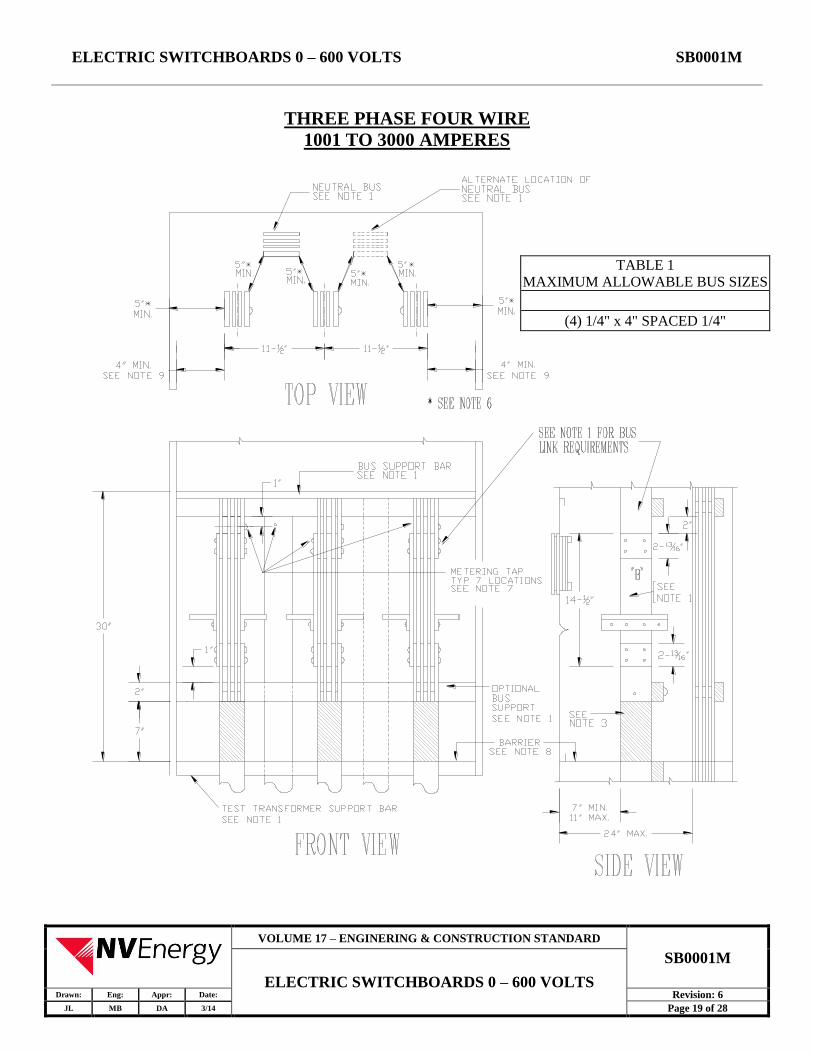
THREE PHASE FOUR WIRE
1001 TO 3000 AMPERES
TABLE 1
MAXIMUM ALLOWABLE BUS SIZES
(4) 1/4" x 4" SPACED 1/4"

ELECTRIC SWITCHBOARDS 0 – 600 VOLTS SB0001M
VOLUME 17 – ENGINERING & CONSTRUCTION STANDARD
SB0001M
ELECTRIC SWITCHBOARDS 0 – 600 VOLTS Drawn: Eng: Appr: Date: Revision: 6
JL MB DA 3/14 Page 20 of 28
NOTES: 1. Bus arrangements and supports shall be provided as shown, except the neutral bus may be located
at either side or on the side wall. Bus units shall be anchored so that busses will remain in position
when section "B" is removed. For details of removable section "B" and the insulated CT support
for 4" bus, see Page 23.
2. Direction of feed shall be vertical and no other conductors shall pass through this compartment. A
neutral bus bar extension shall be provided in the instrument transformer compartment above the
lower current transformer bus support when the service section phase busses are supplied from
horizontal cross bussing.
3. Bus units shall be insulated as shown and the insulating material shall be rated for the serving
voltage. Round bus corners as necessary to prevent damage to insulation.
4. Transformer compartment shall be on the supply side of the main switch or breaker.
5. For underground service installed by NVE, the busses shall extend into the pull section as per Page
9.
6. The maximum permissible bus unit shall be as noted in Table 1.
7. Taps for attachment of meter wiring shall be provided as follows:
a. One tap on each upper and lower phase bus unit with a #10-32 UNC screw and washer
provided for each phase bus in either the upper or lower position.
b. One tap on the neutral bus as shown.
8. Clearance to the side of the compartment shall be increased by the amount by which the corner
angle exceeds one inch.
9. Dimension measured to inside edge of the compartment access opening.
10. Barrier shall be insulating non-tracking material and have a minimum of 24 vent holes of 3/8"
diameter.
11. The barrier should not be less than 45" and shall not be more than 50" above the standing surface.

ELECTRIC SWITCHBOARDS 0 – 600 VOLTS SB0001M
VOLUME 17 – ENGINERING & CONSTRUCTION STANDARD
SB0001M
ELECTRIC SWITCHBOARDS 0 – 600 VOLTS Drawn: Eng: Appr: Date: Revision: 6
JL MB DA 3/14 Page 21 of 28
THREE PHASE FOUR WIRE
3001 AMPERES AND LARGER
TABLE 1 MAXIMUM ALLOWABLE BUS SIZES
(4) 1/4” x 4” SPACED 1/4”
(6) 1/4” x 5” SPACED 3/8”
(4) 3/8” x 5” SPACED 3/8”
(5) 3/8” x 5” SPACED 3/8”

ELECTRIC SWITCHBOARDS 0 – 600 VOLTS SB0001M
VOLUME 17 – ENGINERING & CONSTRUCTION STANDARD
SB0001M
ELECTRIC SWITCHBOARDS 0 – 600 VOLTS Drawn: Eng: Appr: Date: Revision: 6
JL MB DA 3/14 Page 22 of 28
NOTES: 1. Bus arrangements and supports shall be provided as shown, except the neutral bus may be located
at either side or on the side wall. Bus units shall be anchored so that busses will remain in position
when section "B" is removed. For details of removable section "B" and the insulated CT support
for 4" bus, see Page 23. For 5" bus, see Page 24. Consult NVE for use of bus larger than 5".
2. Direction of feed shall be vertical and no other conductors shall pass through this compartment. A
neutral bus bar extension shall be provided in the instrument transformer compartment above the
lower current transformer bus support when the service section phase busses are supplied from
horizontal cross bussing.
3. Bus units shall be insulated as shown and the insulating material shall be rated for the serving
voltage. Round bus corners as necessary to prevent damage to insulation.
4. Transformer compartment shall be on the supply side of the main switch or breaker.
5. For underground service installed by NVE, the busses shall extend into the pull section as per Page
9.
6. The maximum permissible bus unit shall be as noted in Table 1.
7. Taps for attachment of meter wiring shall be provided as follows:
a. One tap on each upper and lower phase bus unit with a #10-32 UNC screw and washer
provided for each phase bus in either the upper or lower position.
b. One tap on the neutral bus as shown.
8. Clearance to the side of the compartment shall be increased by the amount by which the corner
angle exceeds one inch.
9. Dimension measured to inside edge of the compartment access opening.
10. Barrier shall be insulating non-tracking material and have a minimum of 24 vent holes of 3/8"
diameter.
11. The barrier should not be less than 45" and shall not be more than 50" above the standing surface.
12. Return flanges for lower and upper meter panel support shall not project more than 3/4" up or
down from adjacent switchboard panels.

ELECTRIC SWITCHBOARDS 0 – 600 VOLTS SB0001M
VOLUME 17 – ENGINERING & CONSTRUCTION STANDARD
SB0001M
ELECTRIC SWITCHBOARDS 0 – 600 VOLTS Drawn: Eng: Appr: Date: Revision: 6
JL MB DA 3/14 Page 23 of 28
REMOVABLE LINK & CT SUPPORT
4" BUS - 3001 AMPS AND LARGER
REMOVABLE LINK ASSEMBLY
(FURNISHED BY MANUFACTURER)
DETAIL "C"
INSULATED SUPPORT FOR CURRENT
TRANSFORMER
(MATERIAL: INSULATING, NON-TRACKING)
DETAIL "A"
DRILLING AND SPACING OF BUSDETAIL "B"1
4"x4" LINK(SAME MATERIAL AS BUS)
NOTES:
1. Manufacturer to secure the removable bus link to the upper and lower CT bus units using 1/2-inch hex
head bolts, nuts (as shown) with a spring washer and a nut.
2. Drill and tap two holes as shown on the outer bus units for 1/4-inch x 20 UNC cap-screws.

ELECTRIC SWITCHBOARDS 0 – 600 VOLTS SB0001M
VOLUME 17 – ENGINERING & CONSTRUCTION STANDARD
SB0001M
ELECTRIC SWITCHBOARDS 0 – 600 VOLTS Drawn: Eng: Appr: Date: Revision: 6
JL MB DA 3/14 Page 24 of 28
REMOVABLE LINK & CT SUPPORT
5" BUS 1001 - 3000 AMPS
REMOVABLE LINK ASSEMBLY
(FURNISHED BY MANUFACTURER)
DETAIL "C"
INSULATED SUPPORT FOR CURRENT
TRANSFORMER
(MATERIAL: INSULATING, NON-TRACKING)
DETAIL "A"
DRILLING AND SPACING OF BUS
DETAIL "B"1
4"x5" LINK(SAME MATERIAL AS BUS)
NOTES: 1. Manufacturer to secure the removable bus link to the upper and lower CT bus units using 1/2-inch
hex-head bolts, nuts (as shown) with a spring washer and a nut.
2. Drill and tap two holes as shown on the outer bus units for 1/4-inch x 20 UNC cap-screws.
3. Consult NVE for use of bus bars larger than 5 inches.

ELECTRIC SWITCHBOARDS 0 – 600 VOLTS SB0001M
VOLUME 17 – ENGINERING & CONSTRUCTION STANDARD
SB0001M
ELECTRIC SWITCHBOARDS 0 – 600 VOLTS Drawn: Eng: Appr: Date: Revision: 6
JL MB DA 3/14 Page 25 of 28
SOCKET METER PANEL
NOTES: 1. The switchboard manufacturer shall drill, tap and slot the panel as shown for secondary test
switches and shall furnish and install sockets complete with sealing rings.
2. Meter sockets installed on hinged panels shall be designed for back connection.
3. Meter panels shall be constructed of 12 gauge steel (minimum) and shall be hinged, reversible,
sealable and interchangeable.
4. Hinges must support a 25-pound load applied at unsupported end with one-eigth inch maximum
sag when open.
5. A handle shall be attached at the unsupported end of the meter panel with a minimum radial
clearance of 1 inch from the meter socket or removable plate section.
6. Hinges shall be readily interchangeable, right or left, on the job site.
7. All securing screws and sealing screws on panel shall be captive. Studs and wing nuts shall be
sealable when used.
8. Meter panels shall be capable of being opened 90º with meter and test facilities in place.
9. Removable plate shall be secured to rear of panel by screws of such length so as not to protrude
through face of panel.
ELECTRIC SWITCHBOARDS 0 – 600 VOLTS SB0001M
VOLUME 17 – ENGINERING & CONSTRUCTION STANDARD
SB0001M
ELECTRIC SWITCHBOARDS 0 – 600 VOLTS Drawn: Eng: Appr: Date: Revision: 6
JL MB DA 3/14 Page 26 of 28
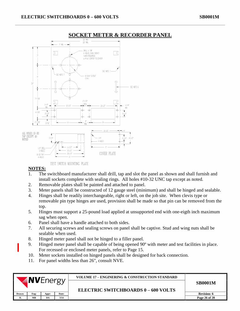
SOCKET METER & RECORDER PANEL
NOTES: 1. The switchboard manufacturer shall drill, tap and slot the panel as shown and shall furnish and
install sockets complete with sealing rings. All holes #10-32 UNC tap except as noted.
2. Removable plates shall be painted and attached to panel.
3. Meter panels shall be constructed of 12 gauge steel (minimum) and shall be hinged and sealable.
4. Hinges shall be readily interchangeable, right or left, on the job site. When clevis type or
removable pin type hinges are used, provision shall be made so that pin can be removed from the
top.
5. Hinges must support a 25-pound load applied at unsupported end with one-eigth inch maximum
sag when open.
6. Panel shall have a handle attached to both sides.
7. All securing screws and sealing screws on panel shall be captive. Stud and wing nuts shall be
sealable when used.
8. Hinged meter panel shall not be hinged to a filler panel.
9. Hinged meter panel shall be capable of being opened 90º with meter and test facilities in place.
For recessed or enclosed meter panels, refer to Page 15.
10. Meter sockets installed on hinged panels shall be designed for back connection.
11. For panel widths less than 26", consult NVE.

ELECTRIC SWITCHBOARDS 0 – 600 VOLTS SB0001M
VOLUME 17 – ENGINERING & CONSTRUCTION STANDARD
SB0001M
ELECTRIC SWITCHBOARDS 0 – 600 VOLTS Drawn: Eng: Appr: Date: Revision: 6
JL MB DA 3/14 Page 27 of 28
SELF CONTAINED METERS (0-200 AMP)
NOTES: 1. Test-bypass blocks with rigid insulating barriers shall be furnished, installed, and wired or bussed
to the meter socket by the manufacturer. Test-bypass blocks and barriers shall conform to NVE
Standards dwg. CM0001M, Pages 5-6, requirements and physical arrangements shall conform to
NVE Standards dwg. CM0001M, Page 10. Connection sequence is line-load, from left to right for
each phase.
2. Metered conductors shall not pass through adjacent metering compartments except in enclosed
wire ways.
3. Meter panels shall be removable with a maximum of two meters per panel.
4. Test-bypass block cover panels shall be sealable and fitted with a lifting handle. All panels
exceeding 16 inches in width shall require two lifting handles.
5. When a neutral is required for metering or testing, an insulated neutral terminal shall be provided
behind each test-bypass cover panel. The terminal shall be readily accessible when the cover panel
is removed and shall be individually connected to the neutral bus with a minimum size #8 AWG
copper wire.
6. Factory installed full-width insulating barrier shall be located at the bottom of each test-bypass
compartment.
7. For 3 phase, 4 wire, connect 7th jaw to body of neutral lug with #8 copper wire.

ELECTRIC SWITCHBOARDS 0 – 600 VOLTS SB0001M
VOLUME 17 – ENGINERING & CONSTRUCTION STANDARD
SB0001M
ELECTRIC SWITCHBOARDS 0 – 600 VOLTS Drawn: Eng: Appr: Date: Revision: 6
JL MB DA 3/14 Page 28 of 28
8. Meter panels shall be removable but shall be non-removable when meter is in place. Meter socket
is to be supported independent of and attached to meter panel.
9. Separate line and load conductors shall be installed by the contractor or manufacturer for each
meter socket.
10. Each line and load position shall be clearly identified by 3/4 inch minimum block lettering
labeling.
11. All securing screws shall be captive. All panels shall be sealable.
11.0 METER SOCKETS
SEE NVE STANDARD GM0001M, FOR TABULATION OF NVE METER SOCKET REQUIREMENTS.