phe product knowledge - spatiul construit · 1999 vicarb acquisition, compabloc & v-series....
TRANSCRIPT

PHE Knowledge
Topics to cover• PHE evolution• PHE function & applications• Current and future PHE range• Plates & gaskets• Frames• Plate gallery tour and Workshop visit• Plate packs• Technological and customer benefits• Product Manual Plates (PMP)

Alfa Laval’s Historical Base1878 19311917
The continuousmilk separatordeveloped byGustaf de Laval
Plate heat exchangersdeveloped to improve pasteurisation process
The first vacuum-operated milking machine

2000 Start of the T-series, FrontLine1999 Vicarb acquisition, Compabloc & V-series
1997 Base-line (Food)1995 Rolls Laval / Spiral C-serie
1994 AlfaRex1993 Nickel Brazed
1992 Clip-Line (Food)1989 Plate evaporator
1987 Graphite plate1986 M-series, module size & thinner plates, Double-wall
1985 Wide-gap1983 Copper Brazed
1980 Semi-welded concept, glue-free concepts1970 A-series with Alfa Flex concept, 0.6 mm
1962 Rosenblad herring-bone pattern1950 Industrial plates in exotic material
1944 Wash-board pattern1938 Pressed plates in 1.0 mm
1931 First Plate Heat Exchanger (1878 a German patent)
Plate Heat Exchanger - evolution

1931 2001
• 5-10 mm thick plate• Milled pattern• Liquids passed the plate
horizontally several times• Stainless steel• Up to 5 m2 per unit
• Down to 0.4 mm plates• Pressed plates• Liquids passes over the whole
plate in one passage• Various materials• Up to 2000 m2 per unit
Plate Heat Exchanger - evolution

1955
P2
Free channel: 2.9 mm
AISI 316: 0.8 mm
Max test pressure: 21 barg
1990
M6-M
Free channel: 3.0 mm
AISI 316: 0.5 mm
Max test pressure: 31 barg
Alfa Laval plate development
Plate Heat Exchanger - evolution

0
10
20
30
40
50
60
70
80
90
100
First PHE
Pressed plate
Washboard pattern
Herringbone pattern
Alfa Flex
B-serie (2.5 mm gap)
M-serie PHEs
T-serie PHEs
Continuous cost reductions through innovations
Plate Heat Exchanger - evolution

PHE - applications
• Steel and metal works
• Power and energy production
• Chemical process industries
• Petroleum industries
• Refrigeration
• Engineering industries
• Central cooling engineering
• Metal recovery industries
• Mineral processing industries
• Sugar, distillery fermentation
• Pulp and paper industries
• Dryers for compressed air
• Heating, ventilation and air conditioning

PHE - main componentsCarrying bar
Pressureplate
Plate packTightening bolts
Frame plate

PHE - 3 dimensional tour
Click on animation to play again

PHE - dismantling
Click on animation to play again

PHE - flow principle
Click on animation to play again

Current PHE range
On Req. 2001On Req. 2001
On Req. 1996On Req. 1996On Req. 2001On Req. 2001

Current PHE range• We have three different PHE ranges
– M-serie PHE
• The majority of our range
• Modern types introduced mainly during the 1990s
– A-serie PHE
• Some units remaining from an old serie
• Introduced during the 1970s and 1980s
– V-series
• Came through the Vicarb acquisition
• Separate lecture on this range

M-serie PHEs• Basic objectives were
– To replace the A-serie with a smaller number of PHE types
– To supply each type with the various plates needed
– To design all plate of a given M-type for same raw sheet material
• Advantages– Less inventory and scrap
– Shorter delivery time
– Reduced tooling investment
– Minimised administration

M-serie PHEs• Features implemented with the M-serie
– Always parallel flow
– Chocolate pattern
– Corner guidance on M10 and smaller models
– Sheet thickness down to 0.4mm
– Glue free gaskets
– Improved pressure and temperature performance
• To a large extent the M-serie has been very success
• We are almost ready with replacing the A-serie
• No time to rest ⇒ Move ahead with the future PHE range

Future PHE range• A brand new series to replace A, M and V-series
• The T-series– Already started with one unit released in 2000
– Next unit to be released end of 2001
• Current range of gasketed PHEs consists of– 1 model in the T-serie
– 11 models in the M-serie
– 3 models in the A-serie (On Request)
– 14 models in the V-serie (some will be obsoleted)

T-serie PHEs• Technical innovation implementation
– Existing innovations as well as those made in the future
– Differentiate performance depending on customer needs• State-of-the-art where customers are willing to pay
• Cost efficient alternatives where customer is price focused
• Total cost optimisation on frames– Smart range planning
– Less frames to be used more frequently• Less frame families
• Less frame types in each family
• Less components and variants on each frame
– Allow variation on components customers care about

T-serie PHEs• Thermal coverage improvements
– Competition sharpens
– Good thermal fit is always the best way to ensure competitiveness
– Larger size PHEs as industrial plants grow larger
– Maintained low-theta coverage on gasketed units
• Principal schedule has been outlined with the motto: – ”A unit per year, keeps customers near, and competitors in fear".
– All units will be developed based on market requirements

T-serie PHEs• Theoretical range lay-out is based on
– Two pressing depths
– Two plate lengths
– In each port size
Theta Low theta Medium High
Length Short Medium Long
Pressing depth 4.0 mm 2.5 & 4.0 mm 2.5 mm

A = PHE serie• A for A-serie• M for M-serie• T for T-serie
C = Pressing depth• B = 2.5 mm• M = 3.5-4 mm• = 3-3.5 mm• Ex, M10-B, M20-M, M30
Denominations8 possible positions in PHE name: A B 12 - C D EF
B = “Extra” feature if any• X = Extra high Θ
in M-serie (MX25-B)• K = Short in A & M-serie: (AK20)• S = Short in T-serie: (e.g., TS20-M)• L = Long in T-serie: (e.g., TL20-B)12 = Port size• 10 = 10 cm (4”)• 20 = 20 cm (8”)• Ex, M6, M15-B
D = Special feature• W = semi-welded• D = double-wall• S = wide-gap• Ex, M10-BW, M6-MDEF = frame design pressure• FM = 10 barg• FG = 16 barg• FD = 25 barg• FS = 30 barg

Naming of connectionsDenomination
T1T4
T2T3
S1S4
S2S3
Frame plate
Pressure plate

Plate - main components
Thin sheet design, cold formed in single step hydraulic pressing (up to 40000 tons)
Main heat transferarea
Distribution area
Suspension
Inlet / outlet Passing through
Gasket in gasket groove
Leak chamber

Plate - corrugation function
• Mechanical – Provide support points
– Allows thin material
• Flow dynamic – Creates high turbulence
– High efficiency
– Minimize fouling
– Cork-screw flow

Plate - corrugation and channels
L: Low theta H: High theta
• We have two plate corrugations (L and H)
L + L = L channels L + H = M channels H + H = H channels
• These form three different channels (L, M and H)
• We choose between L, M and H channels• Tailor-make it for the specific duty

Plate - corrugation and channels
Advantages• Efficient heat transfer• High wall shear stress• Variable thermal length• Strong construction
Benefits• Increased heat recovery• Low fouling• Optimal design• Insensitive to vibration
Low turbulence& pressure drop
L + L = L channels
Medium turbulence& pressure drop
L + H = M channels
High turbulence & pressure drop
H + H = H channels

Plate - pressing depth
Performance
Pressing depth
• pressure drop• heat recovery• compact design
• gentle product treatment• special products• clogging problems
Thermal Product
• Alfa Laval has a range of pressing depths from 1.5 mm to 11 mm for optimal solution to any dutyThere is no good and no bad pressing depth. Just different ones to fit various duties

Plate - pressing• Singles-step pressing of all Alfa Laval plates
• Advantages– Plates are totally uniform
• Gaskets fits to the plates• Plates fit together in the plate pack
– Metal-to-metal contact in all contact points
– Strong plates that can handle• Pressure chocks• Vibrations• Fatigue• High operating pressures• High differential pressures

Plate - distribution area• Chocolate pattern
– Distributes flow evenly over the plate
– Same ΔP for distance A and B
– Uses a minimum of ΔP for distribution
– Gives more ΔP for efficient heat transfer
– Allows parallel flow configuration
– Alfa Laval innovation
• Patent has expired
• Competitors has copied us
A B
– Avoids dead-spots in the far corner
• Full use of heat transfer area
• No fouling in stagnant zones

Plate - parallel vs diagonal flow
Parallel flow configuration is achieved through the chocolate pattern
Parallel Diagonal

Plate - parallel vs diagonal flow
Parallel flow advantages
• One plate & one gasket– Identical plates in the plate pack
– Rotated 180º to achieve both sides
• Less spares required
• Fully supported diagonal
– Higher design pressure or thinner plate material
• No crossing of nozzles
180º

Plate - materials• Standard materials and thicknesses
– AISI 304 (stainless steel)• Usually 0.4 or 0.5 mm thickness• Cheapest possible solution
– AISI 316 (stainless steel)• Always 0.5 and 0.6 mm• Some with thicker plates (high-pressure applications)
– 254 SMO (high-alloy stainless steel)• Usually in 0.6 mm to allow stock-keeping
– Titanium • Always 0.5 and 0.6 mm• Some with thicker plates (high-pressure applications)• Some PHEs with 0.4 mm (low-pressure applications)
– Alloy C-276 (Nickel alloy)• Usually in 0.6 mm to allow stock-keeping
100%
115%
250%
300%
600%
Relative Price

Plate - materials• Standard materials and typical uses
– AISI 304• Typically in clean water-water duties• Example, up to 50 ppm chlorides at 50°C
– AISI 316• Typically in water-water duties• Example, up to 250 ppm chlorides at 50°C
– 254 SMO (high-alloy stainless steel)• Many uses including high-chloride water-water duties• Example, up to 6000 ppm chlorides at 50°C
– Titanium • Most frequent use is for sea water (3.5% chlorides)• Example, up to 130°C in sea water
– Alloy C-276 (Nickel alloy)• Most frequent use is for concentrated sulphuric acid up to 90°C

Plate - materials• Common exotic materials
– Not always on stock
– Check with Supply Unit before quoting and confirm before order
– 904L is an alternative to 254 SMO in some applications
– Nickel 200/201 is mainly for sodium hydroxide production
– Titanium Palladium
• For sea water at high temperature (>130°C)
• For high concentrated chloride brines at high temperature
– Alloy G-30 is used in the sulphuric acid application (scrubber)
– Alloy D-205 is exclusively for concentrated sulphuric acid >90°C
• Many more are used less frequently on a case-by-case basis

Plate - material
• How to know which plate material to use?– Application Manual
– Contact the Market Segment
– Ask the customer
– Testing with small test-pieces in the customers process

Plate - hanger slot reinforcement
• Reinforces the plate hanging
• Stainless steel spot welded to the plate
• Used on M20 and larger plates

Gasket - advanced sealing system
Long lasting gaskets!
...or glue-free gasket that do not mix sealing and fastening function
Two component oven-cured epoxy glue
“Roof-top” gasket profile
Supporting and protecting gasket groove
Gasket material from certified suppliers
Homogeneous rubber gasket made in one piece

Gasket - profile and groove
Profile
CompetitorAlfa Laval
Groove
Higher sealing pressure
Risk of leakage.
Full support to gasket Openings. Risk of
gasket blow-out.
The difference is life time and reliability

Gasket - double sealing systemSpecial venting ports are an integral part of the gasket design to prevent cross contamination
If the gasket fails ⇒ Leakage is detected on the outside

Gasket - materials• The choice of rubber material depends on
– Fluids - chemical attack or not– The combination of temperature and pressure
• Rubber materials change properties due to– Time - the rubber relaxes– Temperature - the rubber deteriorates– Hardening by attack of oxidising agents (e.g., oxygen in air)– Swelling or softening by absorption of chemicals in the fluids
• Common gasket types– Nitrile– EPDM– FKM
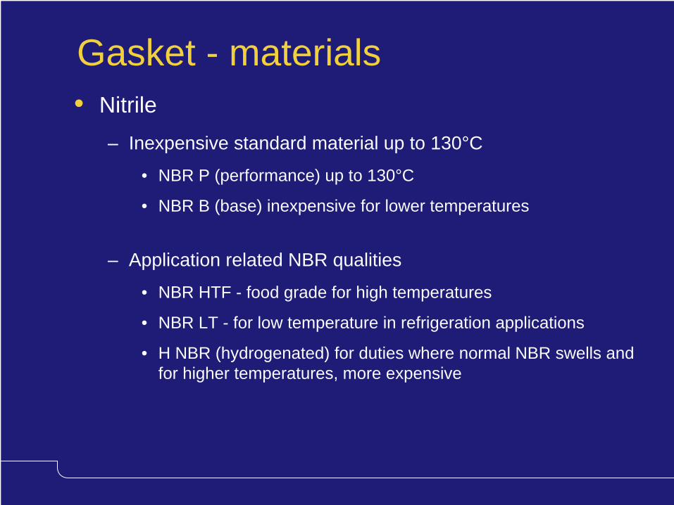
Gasket - materials• Nitrile
– Inexpensive standard material up to 130°C
• NBR P (performance) up to 130°C
• NBR B (base) inexpensive for lower temperatures
– Application related NBR qualities
• NBR HTF - food grade for high temperatures
• NBR LT - for low temperature in refrigeration applications
• H NBR (hydrogenated) for duties where normal NBR swells and for higher temperatures, more expensive

Gasket - materials• EDPM
– Standard material up to 160 °C
– Standard EPDM qualities
• EPDM for glued gaskets (“Crushing resistant”)
• EPDMC for clip-on gaskets at high temperature
• EPDMCT as above but for thin gaskets in models with low pressing depth (1.5-3 mm)
– Application related EPDM qualities
• EPDMF - food grade
• EPDM AL for increased pressure resistance in certain chemical duties where normal EPDM swells

Gasket - materials• FKM, Fluorocarbon rubber
– Often called Viton (DuPont trade name)
– Used for aggressive chemical compounds
• Sulphuric acid
• Aromatic organic compounds
• Chlorinated organic compounds
– Two different qualities used
• FKM G
• FKM S
• Other types are Neopren, Hypalon, Chloroprene, etc.

• Typical composition of a PHE gasket
Gasket - composition
Rubber Polymer ~50% EPDM, NBR
Filler 30-40% Carbon black
Curing agents 2-10% Sulphur, peroxides
Metallic oxides 1-5% ZnO,PbO,CaO
Antidegradants 0-5% Amines, phenols
Processing Aids 0-5% Mineral oil
CONSTITUENT CONTENT EXAMPLES
Exact composition is the know-how of the gasket supplier

Gasket - temperature
Rubber compound Gasket
• NBRB continuous 150 ºC <130 ºC
• NBRB intermittent 170ºC <130 ºC
• Temperature performance of a PHE gasket is lower than that of the rubber compound– The rubber compound must not deteriorate
– The gasket must seal

Gasket - glued fastening• Alfa Laval uses 2-component oven cured epoxy glue• Average gasket lifetime in years for the same application,
opened once a year
Rubber glue
Years
Rubber glueoven cured
2-componentepoxy glue,oven cured
5
10A
lfa L
aval
Competitors

Gasket - glued fastening• The four parameters creating a perfect glue bond
Compression
Glue curing Clean gasket
Clean plate groove
!
• A perfect bond with 2-component oven cured epoxy sticks to the plate. Only loosens if the gasket is torn.

Gasket - glue free fastening
• Fastening and sealing are kept separate
• If the one of the fastener breaks, the gasket still stays sealed
• Clip-on is mostly used (snap-on on a few older models)
Clip-on Snap-on
Sealing
Fastening

Gasket - glued versus glue-free
Should be the choice of the customer
...BUT glued is preferred:
• On large plates
• When units are opened frequently
• On high pressure duties
• When the gasket will be swelling due to chemical attack

Gasket - sealing lifetimeProduct
• Gasket material
• Fastening
– Glue or glue-free
– Type of glue
• Gasket geometry
• Gasket groove
• Alignment of plate pack
Duty
• Operating temperature
• Operating pressure
• Media
• Type of operation continuous / cyclic
• Cleaning methods & chemicals
• Opening frequency
Life time!

Gasket - sealing lifetime• Maximum temperature in CAS and product manual,
for example,– NBR up to 130ºC
– EPDM up to 160ºC
⇒
Gives about 1 year lifetime When no chemical attack takes place
• Rule of thumb:– 10ºC lower than max temperature ⇒ 2 years lifetime
– 10ºC above the max temperature ⇒ 6 months lifetime

Gasket - sealing lifetime• Temperature
– Considered in CAS
– Selects a gasket which gives minimum 1 year lifetime at the design temperature
– Manual check if other gasket is needed to get longer lifetime
• When aggressive fluids are present– Gasket Selection Guide programme
– Ask the customer
– Contact the Market Segment
– Testing with small test-gaskets in the customers process

Gaskets - cold leakageGasketforce
Time
Limit for proper sealing
Assembly
TransportationInstallation
Stop (cold)
Operation(hot)
Stop (cold)
Stop (cold)
Operation(hot)
Operation(hot)
ColdLeakage
• Cold leakage appears when the unit is started-up
• When it is heated up it seals again
• Gaskets probably need to be replaced at next planned stop

Frame - components Carrying bar
Pressure plate
Tightening bolts
Frame plateSupport column
Studbolt connections
Guiding Bar
All-bolted construction for easy on site assembly and repair

Frame - M15 and larger
• Carryings bar in Aluminium or Painted carbon steel
• Support columns in Aluminium or Painted carbon steel
• Guiding bars in Stainless Steel
Carrying bars
Support columns
Guiding bars

• Unique 5-point alignment system– Provides exact positioning
of the plates horizontally and vertically
– Ensures good sealing throughout the plate pack
Carrying bar
Guiding bar
Plate
Frame - M15 and larger

Frame - M15 and larger• Tightening bolts to allow easy opening
— Bolt head— Bearing box
— Plastic cover— Lock washer
— Nut— Rolled thread

• Remaining bolts with wearing washer
– When closing these are tightened last
– When opening these are removed first
Frame - M15 and larger
• Four tightening bolts have bearing boxes
• These are used for opening and closing the unit
• Tightening bolts to allow easy opening

• Bolt head fixated
• Does not loosen when opening
• Lock washer
• Prevents bolt to fall out during tightening and opening
Frame - M15 and larger
• Tilted bolt opening
• Prevents bolts to fall out when loose
• Tightening bolts to allow easy opening

Frame - M15 and larger
• Roller on pressure plate to allow easy opening and closing

Frame - M15 and larger
• One man can open and close a large PHE using standard tools
• Serviceability
• Less downtime
• Safety
• Longer lifetime

• Smaller units requires less features
• Smaller means easier to handle
• Cost efficiency important
Frame - M10 and smaller
• Appropriate bolting system
– Less tightening forces required
– Tilted bolt opening
– Wearing washer in plastic
– Lock washer
– Fixated bolt head

Frame - M10 and smaller
• Carryings bar, Support columns and Guiding bar in Aluminium
• No roller needed due to low weight pressure plate
Round guiding bar
Support column
Round carrying bar

Frame - M10 and smaller
• First alignment made by the round carrying & guiding bar
• Corner guidance locks the plates in position and fine- tunes the alignment
• Effective and cost efficient

Frame - connections and linings• Studbolts around the connection
• Connection pipes are bolted to the PHE
• Three different types of liningsUnlined
• Cheapest possible
• Clean water duties
Rubber lining
• Low cost
• Limited in temperature
• NBR and EPDM
Metal lining
• More expensive
• Industrial use
• Same as plate material

Frame - blind covers
• Used in multi-pass to seal off unused connections
• When 2- or 4-holed pressure and frame plates are standard
• M15 and smaller with inside cover only (3)
• M20 and larger blind cover, inside cover and spacing piece (1-3)
1 External cover2 Spacing piece3 Blind cover
33

Frame - inspection covers
• Used to allow inspection in the port without dismantling the pipes
• Used with holed end plate and pressure plate
1 Flange2 Adhesive3 Metal sheet4 Gasket

• Safety issue• Protects personnel in case of leakage• Stainless steel (M15 and larger)• High-resistant plastic (M10 and smaller)• Customers choice• Recommended for hazardous duties
– Temperatures over 60°C– pH less than 3 (acidic)– pH over 10 (alkaline)– Toxic, poisonous or flammable
fluids under pressure
Frame - protection sheets

Frame - feet
• Gives stability
• PHE bolted to foundation
• Standard on M15 and large
• Option on M10 and smaller
• Painted carbon steel
• Hot-dip galvanised

• For safe and easy lifting of the unit in manufacturing and at site
• On all units except M3
Frame - lifting holes

Frame - painting systems
– Standard
• Sandblasting
• Primer - 2 part epoxy
• Finish - 2 part epoxy
• 90-135 microns
– Special
• Sandblasting
• Primer - zinc rich epoxy
• 2 coatings - iron oxide epoxy
• Finish - 2 part polyurethane
• 240-315 microns
• Choice of colours
• Choice of tested paint systems
• Examples,
• Specifically developed for PHE
– Too thick ⇒ Paint is crushed behind end-plates
– Too thin ⇒ Inadequate protection
– Alfa Laval system balances hardness & thickness

Frame - pressure vessel codes• All PHEs available as standard with
– TUV• Always DIN connection standard
– ASME• Always ANSI connections standard
– SA• DIN connections
• ANSI connections
• Contract orders– Various national codes available at extra cost
– Example, BS5500 (UK), Codap (France) and Ispels (Italy)

Plate gallery & Workshop visit
• Plate gallery tour to view historic PHEs, the evolution and samples of modern PHEs
• Workshop tour to have a hands-on look at the frame components

Plate pack assembly
• Channel Plate
• End Plate II
• End plate I
• Turn Plate
• Transition Plate
• Partition Plate
• Connection Plate
End plate II
End plate I

Plate pack - channel plates
• Channel Plates are the heat transfer plates
• They dominate the plate pack
• Most frequently with 4 holes punched

Plate pack - end plate II
• 1st plate at the carbon steel frame plate
• In multi-pass, 1st plate in each pass
• Prevent the fluids from coming in contact with the painted carbon steel frame plate
• All 4 ports sealed off
• Transports the fluids
– From the connections in the frame plate
– To the first channel plate
• Usually in 0.6 mm with high-theta
(On older models the End Plate II is at the end of the plate pack)

Plate pack - end plate I• In single pass,
– Stops the fluid at the end of the plate pack– Last plate at the carbon steel pressure plate– No port holes are cut out
Sing
le p
ass
Exam
ple,
M
ulti
pass
• In multi-pass,– Stops one fluid as it reaches the end– Allows the other to flow into the plate pack– 2nd last plate in the plate pack
(transition plate behind it)– Hole combination as per pass arrangement
• Normal gasket as on channel plates• Usually in 0.6 mm with high-theta
(On older models the End Plate I is at front of the plate pack)

Cold inHot out
Hot inCold out
Plate pack - example single pass
End
Pla
te II
End
Pla
te I
Cha
nnel
pla
tes
Only 2 plates that do not transfer heat - the endplates

Plate pack - turning plate
• Used in multi-pass
• 1, 2 or 3 port can be unholed
• Change the flow direction of one or both fluids in between the passes
• Normal channel plate gasket

Plate pack - partition plate
• Used in multi-pass
• Solid carbon steel plates (6-12 mm thick)
• Metal ring in same material as the plate pack
• Used behind turning plates to support it from the pressure of the flow in the unholed port Turning
plate
Partition plate
Unholed port

Plate pack - transition plate• Used in multi-pass
• Last plate in each pass (behind Turning plates and End plate I)
• Prevents the fluids to come in contact with partition plates and the pressure plate
• Special port ring-gaskets
– Protrude through the plate
– Allows a seal on both sides of the plate
– Lined on the inside perimeter with a metal ring
• Always, plate in AISI 316 and field gasket in NBR
• Metal ring in the same material as the plate pack
• Ring gaskets in the same material as the plate pack

Plate pack - transition plate
Pressure plate
Metal lining
Channel plates
End plate 1
Transition plate in AIS 316 0.6 with NBR field gasket
Special ring gasketCollar metal ring

Plate pack - partition plate• Partition plate rules
– M20 size and large
• Always partition plate behind turning plate
– M15 size
• Double turning plate if flow rate < 75 kg/s
• Partition plate if flow rate > 75 kg/s
– M10 size and smaller
• Single turning plate is Ok
– Any unit with 3 fluids or more require partition plate
• Mainly in Marine applications (combi-coolers)

Plate pack - example two pass
End
Pla
te II
Turn
ing
plat
e
Cha
nnel
pla
tes
Cold inHot outHot in
Cold out
End
Pla
te I
End
Pla
te II
Tran
sitio
n pl
ate
Par
titio
n pl
ate
Cha
nnel
pla
tes
Tran
sitio
n pl
ate
3 plates in each pass that do not transfer heat

Plate pack - the A measure• A-measurement
– The length of the compressed plate pack in mm
– Distance between the inside of the frame and pressure plate
– No. of plates * (plate pressing depth + plate thickness)
• Very important that the A-measure is correct at each tightening bolt to avoid deformation of plates or leakage

Plate pack - number of plates• Maximum number of plates is limited due to
– The more plates, the harder it is to get perfect alignment
– If the the plates are not aligned, it will leak
– Max. allowed length of carrying bar and tightening bolts
– … and of course that ΔP in port can be too high
• Minimum number of plates is limited due to– The elongation of tightening bolts when the unit is pressurised
– Risk of leakage when few gaskets must compensate
– Min. no. of plates ranges from 10-30 depending on PHE model
– Option: ¨dummy¨ 0-hole plates can be added at the back of the plate pack minimise the needed compensation of the gaskets
• Considered in CAS and PMP

Alfa Laval technology benefitsFeature Advantage Benefit
Herringbone pattern Promotes turbulence High heat transfer & less foulingMany contact points Strong plates & thinner plates
Chocolate pattern No dead spots Less fouling & corrosionHigher heat transfer
Roof-top gasket & Higher pressure Lower investment (thin plates)fully supported gasket Gasket stays in place Avoids gasket blow-outgroove Longer gasket lifetime
Single step pressing Uniform thickness No weak spots
2-component oven Sticks to the plate Longer gasket lifetime cured epoxy glue
Clip-on concept Easy replacement Quick replacement

Alfa Laval technology benefitsFeature Advantage Benefit
5-point alignment Exact positioning Good sealing throughout the Corner guidance of the plates plate pack
Bearing boxes and Easy to open and Serviceability, one man canwearing washers close the unit open and close even large units
Tilted bolt openings Tightening bolts stays Safety and serviceabilityLock washers in place during & afterFixed bolt heads opening & closing

Customer benefits• Low investment cost
– Less heat transfer area due to high thermal efficiency and low material consumption
– Exotic materials ⇒ PHE is even more cost efficient
• Low cost for for future expansion– Flexible construction– Bolted frames– Easily to add/remove heat transfer area
• Low installation costs– Low weight (up to 125 m2/ton) – Compact design (100 m2 /m3)– Less space required ⇒ More compact process– Less investment in piping and foundations

Customer benefits• Low maintenance costs
– Speedy cleaning
• Easy dismantling & full access to heat transfer area
• High heat transfer ⇒ Less area to clean
• Low hold up volume ⇒ Chemical cleaning effective
• Glued gaskets sticks to the plate ⇒ Less downtime for cleaning
• Glue free concept ⇒ Quick replacement during service
– Longer operating periods
• High turbulence ⇒ Low fouling ⇒ Longer operating periods
• Quality plates, gasket, groove and fastening ⇒ Longer lifetime
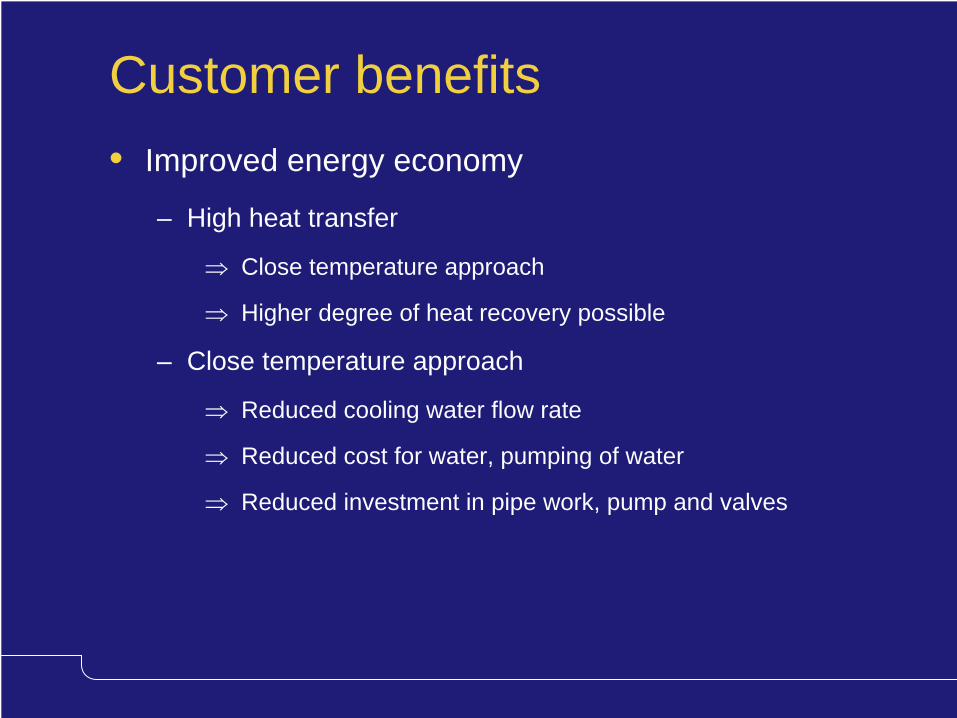
Customer benefits• Improved energy economy
– High heat transfer
⇒
Close temperature approach
⇒
Higher degree of heat recovery possible
– Close temperature approach
⇒
Reduced cooling water flow rate
⇒
Reduced cost for water, pumping of water
⇒
Reduced investment in pipe work, pump and valves

Customer benefits• Improved productivity, quality, safety and reliability
– Easy to regulate due to low hold up volume (< 0.75 l/m2)
• Quick response time
• Less risk of process problems
– Less risk of unplanned stops
• Quality gaskets, gasket groove and gasket fastening
• Gasket stays in place
• Less risk of gasket blow-out
• Environmentally efficient– High efficiency ⇒ High degree of heat recovery
– Low material consumption
– Pure materials that are easy to recycle

Product Manual Plates (PMP)Most of the product information is in CAS
…But CAS only show what is priced…PMP contains more information
…PMP is the “bible”
• PMP available on– ALRound – CD software distribution
• Contains all “Lund” products– Gasketed PHEs– Wide-gap PHEs– Semi-welded PHEs– Graphite PHEs– Double-wall PHEs– Plate Evaporators– Food PHE types
• Does not contain– V-serie PHEs (separate PMP)– Compabloc (separate PMP)

PMP - main screen
Different product models
A separate lecture
Information about different packaging, construction and documentation
When you need data on an old PHE type
You can generate the manual here

PMP - product types
Compact information on framesAll information on plates & gaskets
Detailed frame informationQuotes drawings

PMP - data sheet• Summary of frames

PMP - data sheet• Important notes for the frames

PMP - data sheet• Plates & gaskets available as standard
Important gasket performance data
Important gaskets notes

PMP - data sheet• Plate performance table
Important plate performance data

PMP - pressure/temperature graph
0
5
10
15
20
25
0 50 100 150Temperature (°C)
Pres
sure
(bar
g)
Performance area
• A P/T graph can be made from data sheet information showing the expected performance of the plate & gasket– The design P/T should be inside the performance area– If P/T is on the line ⇒ 1 year gasket lifetime– If P/T is outside ⇒ Cannot guarantee the performance– If the gasket is chemically attacked ⇒ more aspects to be added
Limited by the max design pressure for the plate
Gasket lifetime limited by the max temperature
Gasket lifetime limited by a combination of pressure and temperature

PMP - pressure/temperature graph• The data is found in the data sheet
– In the gasket performance table• T(T) = The maximum allowed operating temperature.
Above this temperature the gasket will last less than one year.
• T(P) = Recommended temperature at max pressure. Higher pressure ⇒ More strain on the gasket ⇒
We cannot allow the max temperature
– In the plate performance table• P(P) = Maximum design pressure for the plate.
Above this pressure the plate will deform.
• P(T) = Recommended max operating pressure at max operating temperature. Higher pressure ⇒ Softer gasket ⇒
We cannot allow the max pressure

PMP - pressure/temperature graph• How to generate the pressures and
temperature graph for a certain case
• Example of a quotation– German customer
– Water-water duty with AISI 316 specified
– Design conditions 110°C and 16 barg
– Thermal design ⇒ M15-B
• Which plate thickness is needed?
• Which gasket can be used?

PMP - pressure/temperature graph• It is a normal water-water duty
– I try to use the standard gaskets with lowest price ⇒ NBR or EPDM
– NBR is maximum allowed up to 110°C and the pressure is as high as 16 barg ⇒ Let’s try with EPDM
– We don’t expect any frequent cleaning ⇒ Clip-on is Ok and with the lowest price

PMP - pressure/temperature graph• It is AISI 316 specified at 16 barg design pressure• German customer ⇒ TÜV design
• Let’s try with AISI 316 0.5 mm – Max design pressure is 20 barg so the plate will not deform– Will it support the gasket enough to last?

PMP - pressure/temperature graph• Now we have the data• EPDM clip-on, T(T)=160°C and T(P)=100°C• AISI 316 0.5 mm, P(P)=20 barg and P(T)=14 barg• Combine it to two data points as per the indices (P) and (T)• For AISI 316 0.5 mm with EPDM c-o
– One point is T(T) / P(T) = 160°C / 14 barg– The other point i s T(P) / P(P) = 100°C / 20 barg – Connect the two points
0
5
10
15
20
25
0 40 80 120 160 200Temperature (°C)
Pres
sure
(bar
g)
T(P) / P(P) = 100°C / 20 barg
T(T) / P(T) = 160°C / 14 barg

PMP - pressure/temperature graph• Mark the design P/T, 100°C and 16 barg
0
5
10
15
20
25
0 40 80 120 160 200Temperature (°C)
Pres
sure
(bar
g)
316 0.5 EPDM clip-on
316 0.5 NBR clip-on
• We are well within the limits• AISI 316 0.5 EPDM clip-on is Ok• Would it have been Ok with 316 0.5 NBR clip-on?
– About 1 year lifetime. What does the customer expect?– NBR and EDPM about the same price ⇒ EPDM
• 316 0.6 NBR clip-on also Ok but more expensive!
316 0.6 NBR clip-on

• In CAS Mechanical configuration– Checks that the duty is inside the performance area
– Does not check if it is a boarder-line case
• If you are not sure do the P/T graph– To see if we are on the boarder-line or not
– To find out which is the best option
PMP - pressure/temperature graph

PMP - frame specifications• Detailed frame information & quote drawing

PMP - packaging

PMP - construction

PMP - documentation

PMP - instruction manuals

PMP - spare parts lists

PMP - obsolete types