ldp, ldp-x seriesdppumps.global/assets/download/dppumps-end-suction-pumps.pdf · the suction and...
TRANSCRIPT


LDP, LDP-X series Fields of application
Water supply Cooling water
Fire-fighting systems Swimming pool water
Sprinkling Sea water
Irrigation Fire-fighting water
Drainage Brackish water
Heating Condensate
Air-con systems Brine
Drinking water Oils
Service water Cleaning agents
Hot water
Operating data Q up to 2000 m3/h
H up to 100 m
Temperature -30 °C to +140 °C
Pressure up to 16 bar
Construction
Type LDP Pumps of the LDP, LDP-X series are horizontal volute
casing centrifugal pumps. The principal dimensions and
performance data of LDP type comply with DIN 24255.
LDP-X type is outside of the official DIN-Norm.
Dimensions can differ from other suppliers.
Type LDP-X
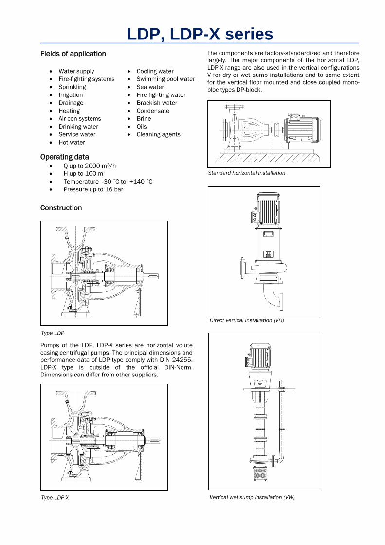
The components are factory-standardized and therefore
largely. The major components of the horizontal LDP,
LDP-X range are also used in the vertical configurations
V for dry or wet sump installations and to some extent
for the vertical floor mounted and close coupled mono-
bloc types DP-block. Standard horizontal installation
Direct vertical installation (VD)
Vertical wet sump installation (VW)

I LDP, LDP-X series
LDP, LDP-X pumps are used primarily for handling clean
or slightly abrasive media. The liquid should not contain
any coarse or highly abrasive solids in order to prevent
operational problems and premature wear. Where
necessitated by the operating conditions the pump.
The suction and discharge flanges are according to
DIN 2501 PN 10 or 16. All pumps are dynamically
balanced according to ISO 1940 class G 6.3 and
impellers are hydraulically balanced.
Due to the pump design the complete bearing assembly
including impeller and shaft seal can be dismantled
without removing the volute casing from the pipe system
(back-pull-out system).
Casing and impeller can be fabricated from special
materials, e. g. zinc-free bronze G-CuSn, SG iron GGG 40,
or Stainless Steel 1.4408. With casing pressures of up
to 16 bar, details on application.
Casing/Impeller The pump casing is of the volute type fitted with a suction
side wear ring. If required, e.g. as part of subsequent
repair work, the gland/seal housing can easily be
machined for a delivery side wearing ring, too.
All impellers are dynamically balanced and hydraulically
relieved by means of compensating bores. Shaft and bearings Pump with overhung bearing housing to DIN 24255.
Shaft rotates in grease lubricated anti friction bearings.
Re-greasing by funnel-type grease nipple. If required, the
bearing housing can be equipped with a support foot at
the drive end. A bearing pedestal is available for heavy
duty drive applications, e.g. V-belts.
Stuffing box with gland packing
Stuffing box with mechanical seal
The standard arrangement is a packed gland for
temperatures up to 110 °C.
For temperatures up to 140 °C a drip-tight maintenance
free mechanical seal, according to DIN 24960
dimensions. Back-to-back double mechanical shaft
seals, and "quench", are available for all variants on
request.
An internal by-pass connects the pump casing with the
stuffing box to ensure lubrication of the gland packing.
When pumping from a vacuum tank or where the liquid
to be pumped contains abrasive particles it is preferable
to feed the stuffing box with an external sealing liquid. In
this event the internal by-pass will be plugged.
Base frame Pump and motor mounted on fabricated steel base
frame which must be fixed with foundation bolts on a
concrete base and subsequently grouted in. base
frames are constructed from welded profile sections.
Coupling Two-component flexible coupling without spacer or
Three-component flexible coupling with spacer. This
coupling allows the removal of the pump rotor without
the need for disconnecting the motor and pipe-work. If
the pump housing, motor or the entire unit is moved,
alignment is always necessary.
All couplings are supplied with a guard.
Motor Pump direct driven by standard B3 foot mounted motor
through flexible coupling.
Direction of rotation is clockwise looking at the pump
shaft end. For maximum permissible speeds, depending
on electric motors with 50 or 60 cycles supply, refer to
page 4.
Spacer coupling
(1) (2)

I LDP, LDP-X series
3
Mounting designation B3 (IM 1001)
Enclosure class IP 55
Insulation class F
Ambient temperature Max. 40°C
Voltages 3 x 220-240/380-415 V
Selection of motors The power required to achieve the requested duty point
can be found by means of the power chart below the
performance chart. Find the power curve corresponding
to the required QH-value (or interpolate between curves).
When deciding the motor size a safety margin acc.
ISO 5199 must be added.
Safety margins according to ISO 5199
Up to required
pump shaft
power: [kW]
Use motor
output P2 :
[kW]
Up to required
pump shaft
power: [kW]
Use motor
output P2 :
[kW]
322 355 15.9 18.5
286 315 12.8 15
227 250 9.1 11
181 200 6.1 7.5
145 160 4.3 5.5
120 132 3.2 4
100 110 2.3 3
81 90 1.7 2.2
68 75 1.1 1.5
49 55 0.81 1.1
40 45 0.55 0.75
32.5 37 0.40 0.55
26 30
0.27 0.37
19 22 0.18 0.25
Ambient temperature Up to +40°C.
Due to the low density and consequent low cooling effect of the
air, operation at an ambient temperature above 40 °C or at an
altitude exceeding 1000 m above sea level requires a
reduction of the rated motor load.

I LDP, LDP-X series
Range (Type LDP)
Pump type
Maximum permissible working pressure 1)
Max. permissible
pump speed 4)
Max. permissible power absorbed kW 2)
Temp. -20 °C up to 110 °C Temp. 110 °C up to 140 °C
Volute material
GG 25 G-CuSn10 GG 25 G-CuSn10
cast iron bronze cast iron bronze 1450 1750 2900 3500 bar bar bar bar min-1 min-1 min-1 min-1 min-1
32-125 10 8 8 6 3600 3,3 4 6,6 8
32-160 10 8 8 6 3600 3,3 4 6,6 8
32-200 10 8 8 6 3600 14,5 17,7 29 35
32-250 10 8 8 6 3600 3) 14,5 17,7 29 35
40-125 10 8 8 6 3600 3,3 4 6,6 8
40-160 10 8 8 6 3600 14,5 17,7 29 35
40-200 10 8 8 6 3600 14,5 17,7 29 35
40-250 10 8 8 6 3600 3) 14,5 17,7 29 35
40-315 10 8 8 6 1800 49 59,8
50-125 10 8 8 6 3600 14,5 17,7 29 35
50-160 10 8 8 6 3600 14,5 17,7 29 35
50-200 10 8 8 6 3600 14,5 17,7 29 35
50-250 10 8 8 6 3600 3) 14,5 17,7 29 35
50-315 10 8 8 6 1800 49 59,8
65-125 10 8 8 6 3600 14,5 17,7 29 35
65-160 10 8 8 6 3600 14,5 17,7 29 35
65-200 10 8 8 6 3600 14,5 17,7 29 35
65-250 10 8 8 6 3600 3) 49 59,8 98 118
65-315 10 8 8 6 1800 49 59,8
80-160 10 8 8 6 3600 14,5 17,7 29 35
80-200 10 8 8 6 3600 49 59,8 98 119
80-250 10 8 8 6 3000 49 59,8 98
80-315 10 8 8 6 1800 49 59,8
100-200 10 8 8 6 3600 49 59,8 98 118
100-250 10 8 8 6 3000 49 59,8 98
100-315 10 7 6 4 1800 49 59,8
100-400 10 7 6 4 1800 3) 120 146
125-250 10 7 6 4 1800 49 59,8
125-315 10 7 6 4 1800 120 146
125-400 10 7 6 4 1800 3) 120 146
150-250 10 7 6 4 1800 49 59,8
150-315 10 7 6 4 1800 120 146
150-400 10 7 6 4 1800 3) 120 146
1) The maximum permissible working pressure includes the pressure at the suction branch (positive suction head) and the maximum generated
head at zero flow (closed valve).
2) If pumps are driven by direct coupled diesel/petrol engines the permissible kW ratings must be reduced by 20%. This also applies to pumps
filled with 1.4401 stainless steel shafts. If the power absorbed by the pump is already at or near the maximum figure then only a nominal motor
kW margin is allowed.
3) Pump output / head at 60 Hz speeds must not exceed the maximum values shown on the corresponding 50 Hz curves.
4) Maximum speeds shown apply to pumps driven via a flexible coupling (direct from motor or stub shaft with plummer blocks). Applications
involving overhung pulleys must be referred to our works specifying the proposed performance data.
Applications involving higher pressures and different casing materials must be referred to our works.

I LDP, LDP-X series
5
Range (Type LDP-X)
Pump type
Maximum permissible working pressure 1)
Max. permissible
pump speed 3)
Max. permissible power absorbed kW 2)
Temp. -20 °C up to 110 °C Temp. 110 °C up to 140 °C
Volute material
GG 25 G-CuSn10 GG 25 G-CuSn10
cast iron bronze cast iron bronze 780 1170 1450 1770
bar bar bar bar min-1 min-1 min-1 min-1 min-1
150-200 10 7 6 4 2000 49 59,8
200-330 10 5 6 4 1800 81 96 120 146
200-400 10 5 6 4 1800 135 161 250 305
200-500 10 6 7 5 1500 135 161 250
250-400 10 5 6 4 1800 135 161 250 305
250-500 10 6 7 5 1500 202 242 315
300-360 6 4 4 3 1800 135 161 250 305
1) The maximum permissible working pressure includes the pressure at the suction branch (positive suction head) and the maximum generated
head at zero flow (closed valve).
2) If pumps are driven by direct coupled diesel/petrol engines the permissible kW ratings must be reduced by 20%. This also applies to pumps
filled with 1.4401 stainless steel shafts. If the power absorbed by the pump is already at or near the maximum figure then only a nominal motor
kW margin is allowed.
3) Maximum speeds shown apply to pumps driven via a flexible coupling (direct from motor or stub shaft with plummer blocks). Applications
involving overhung pulleys must be referred to our works specifying the proposed performance data.
Applications involving higher pressures and different casing materials must be referred to our works.
Standardized versions of materials
Category 0 Category 2 Category 3 Category 4 Category 5 Category 13 Volute casing Cast Iron GG25 Cast Iron GG25 CuSn10 Cast Iron GG25 Cast Iron GG25 AISI-316
Discharge cover Cast Iron GG25 Cast Iron GG25 CuSn10 Cast Iron GG25 Cast Iron GG25 AISI-316
Impeller Cast Iron GG25 CuSn10 CuSn10 Bronze SAE 40 Cast Iron GG25 AISI-316
Wear rings Cast Iron GG25 CuSn10 CuSn10 Cast Iron GG25 Cast Iron GG25 AISI-316
Shaft Ck60 AISI-304 AISI-304 AISI-420 AISI-420 AISI-316
Shaft sleeve Stainless Steel Stainless Steel Stainless Steel Stainless Steel Stainless Steel Stainless Steel
Bearing bracket Cast Iron GG25 Cast Iron GG25 Cast Iron GG25 Cast Iron GG25 Cast Iron GG25 Cast Iron GG25

I LDP, LDP-X series
Sectional drawings – part lists
Type LDP
LDP type sectional view (gland packing)
Detail for mechanical seal
Part number to VDMA Part name Part number to VDMA Part name
102 Casing 452 Stuffing box gland
161 Casing cover 459 Stuffing box bushing
210 Shaft 461 Stuffing box packing
230 Impeller 477 Spring
321 Ball bearing 502 Wear ring
330 Bearing bracket 507 Deflector
360 Bearing cover 922 Impeller nut
412 Casing O-ring 932 Retaining ring for bores
433 Mechanical seal 940 Key

I LDP, LDP-X series
7
Type LDP-X
LDP-X type sectional view (gland packing)
Detail for mechanical seal
Part number to VDMA Part name Part number to VDMA Part name
102 Casing 461 Stuffing box packing
161 Casing cover 471 Seal cover
210 Shaft 477 Spring
230 Impeller 502 Wear ring
321 Ball bearing 507 Deflector
330 Bearing housing 524 Shaft sleeve
360 Bearing cover 636 Grease nipple
412 O-Ring 895 Supporting foot
422 Sealing ring 922 Impeller nut
433 Mechanical seal 932 Retaining ring for bores
452 Stuffing box gland 940 Key
459 Stuffing box bushing

I LDP, LDP-X series
Bare shaft pump dimensions
Type LDP
Pump
size
Dimensions (mm)
NWS NWD Length Height Feet & support mounting details Shaft end
x* a f 1 h1 h2 b m1 w p S1 m2 n1 n2 S2 d1 l1 t u
32-125
50 32 80
360
112 140
50 100
260
110
M12
70
190 140
14
24 50 27 8
110
32-160 132 160 240 190 80
32-200 160 180
32-250 100 180 225 65 125 95 320 250 100
40-125
65
40
80 112 140
50 100 70
210 160 110
40-160 132 160 240 190 85
40-200 100
160 180 265 212
40-250 180 225 65 125 95
320 250 100
40-315 125 470 225 250 330 345 280 32 80 35 10 105
50-125
50 100 360
132 160
50 100 260
70
240 190
24 50 27 8
120
50-160 160
180 265 212
90
50-200 200 100
50-250 180 225
65 125 95
320 250 110
50-315 125 470 225 280 330 345 280 32 80 35 10 105
65-125
80 65
100 360
160 180
260 280 212
24 50 27 8
125
65-160 200 100
65-200 180 225 320 250
65-250 200 250 80 160 330 M16 120
360 280 32 80 35 10
120
65-315
100
125
470 225 280 400 315 105
80-160
80
360 180
225 65 125
260 M12 95
320 250 24 50 27 8
80-200
470
250
330
345 280
32 80 35 10
150
80-250
125
225 280
80 160 M16 120
400 315 125
80-315 250 315 130
100-200
100
200 280
360 280 155
100-250
140
225 400 315 140
100-315 250 315
100-400 530 280
355
100 200 360 M20 150 500 400 42 110 45 12 155
125-250
150 125
470 250 80 160 330 M16 120 400 315 32 80 35 10 140
125-315 530
280
100 200 360 M20 150
500 400 42 110 45 12
150
125-400 315
400
160
150-250
200 150 160
470 280
450
32 80 35 10 140
150-315 530 550 42 110 45 12
160
150-400 315 450 165
* x : Back pull-out distance required between motor shaft end & pump shaft

I LDP, LDP-X series
9
Type LDP-X
Pump
size
Dimensions (mm)
NWS/NWD Length Height Feet & support mounting details Shaft end
a f1 h1 h2 b m1 m2 m3 m4 n1 n2 n3 n4 w S1 S2 d1 l1
150-200 200/150 160 470 280 370 100 200 150 - - 550 450
- - 456
M20
- 32 80
200-330
250/200 200
552 325 450 100
250
200 28 50
160 110
392
M12
42
110 200-400 660 370 470 125
45
80 700 575 465
55 200-500 656 400 560 150 780 630 461
250-400 300/250
250
670 370 500 125 700 575 475
250-500 690 400 560 150 300 250 80 780 630
470 60 140
300-360 350/300 495 55 110

I LDP, LDP-X series
Notes

I LDP, LDP-X series
11
Notes

I LDP, LDP-X series
Notes

