issue 63 nz geomechanics news - amazon web services · 2016-09-07 · in an earlier article in nz...
TRANSCRIPT

NZ Geomechanics NewsJune 2002
1SSN 0111–6851
Issue 63
Newsletter of the New ZealandGeotechnical Society Inc.

Leaders inEngineered
Environmental Solutions
- WallsGabions
TerrameshPrecast Panels
Segmental Blocks
- Slopes & EmbankmentsTerramesh Green
TensarBasal Reinforcement
FortracRockfall Netting
- GeotextilesBidim non woven
MacTex woven
Terrafix non woven
- Road PavementsTensar SS
SealmacTensar ARG
Bitac
- DrainageMegaflo
CordrainPlazadeckEnkadrain
Colbondrain
- LinersBentofix GCL
Proflex FPPAeon Elvaloy
GSE HDPE
Sludge Dewatering Tubes
- CoastalSoft Rock Tubes
Soft Rock Containers
- ErosionBioMac C&W
EnkamatEcocell
Reno MattressWater Logs
Biopins
- SedimentSilt Fences & Accessories
Flotation CurtainsFlexible FlumesSediment Tubes
Phone: [email protected] www.maccaferri.co.nz
•INVERCARGILL •QUEENSTOWN •DUNEDIN •CHRISTCHURCH• WELLINGTON • PALMERSTON NORTH • HASTINGS • TAURANGA • AUCKLAND
stock
for all your Geosynthetic Solutions

Guest Editorial . . . . . . . . . . . . . . . . . . . . . . . . . . . . . . . . . . . . . . . . . . . . . . . . . . . . . . . . . . . . . . . . . . . . . . 2Chairman’s Corner . . . . . . . . . . . . . . . . . . . . . . . . . . . . . . . . . . . . . . . . . . . . . . . . . . . . . . . . . . . . . . . . . . 4Editorial . . . . . . . . . . . . . . . . . . . . . . . . . . . . . . . . . . . . . . . . . . . . . . . . . . . . . . . . . . . . . . . . . . . . . . . . . . . . 5Editorial Policy . . . . . . . . . . . . . . . . . . . . . . . . . . . . . . . . . . . . . . . . . . . . . . . . . . . . . . . . . . . . . . . . . . . . . . 6Report from the Secretary . . . . . . . . . . . . . . . . . . . . . . . . . . . . . . . . . . . . . . . . . . . . . . . . . . . . . . . . . . . . 7Letters to the Editor . . . . . . . . . . . . . . . . . . . . . . . . . . . . . . . . . . . . . . . . . . . . . . . . . . . . . . . . . . . . . . . . . . 8International Society Reports . . . . . . . . . . . . . . . . . . . . . . . . . . . . . . . . . . . . . . . . . . . . . . . . . . . . . . . . . . 9NZGS Branch Activities . . . . . . . . . . . . . . . . . . . . . . . . . . . . . . . . . . . . . . . . . . . . . . . . . . . . . . . . . . . . . . . 13Conference Reports . . . . . . . . . . . . . . . . . . . . . . . . . . . . . . . . . . . . . . . . . . . . . . . . . . . . . . . . . . . . . . . . . 16Standards, Law & Industry News
International Geotechnical Services Directory . . . . . . . . . . . . . . . . . . . . . . . . . . . . . . . . . . . . . . . . . . 21Australasian Chapter of the International Geosynthetics Society . . . . . . . . . . . . . . . . . . . . . . . . . . . 23Auckland Structural Group Piling Specification . . . . . . . . . . . . . . . . . . . . . . . . . . . . . . . . . . . . . . . . . 25
Book ReviewsSubsurface Drainage for Slope Stabilization . . . . . . . . . . . . . . . . . . . . . . . . . . . . . . . . . . . . . . . . . . . . 28Groundwater Lowering in Construction – A Practical Guide . . . . . . . . . . . . . . . . . . . . . . . . . . . . . . 29Influence of Gravity on Granular Soil Mechanics . . . . . . . . . . . . . . . . . . . . . . . . . . . . . . . . . . . . . . . 30Testing, Observation, and Documentation . . . . . . . . . . . . . . . . . . . . . . . . . . . . . . . . . . . . . . . . . . . . . 31
Project NewsResearch Update From the University of Auckland Geology Department . . . . . . . . . . . . . . . . . . . . 35State Highway 6 – Nevis Bluff Stabilisation Contract . . . . . . . . . . . . . . . . . . . . . . . . . . . . . . . . . . . . 36Cosseys Dam Upgrade . . . . . . . . . . . . . . . . . . . . . . . . . . . . . . . . . . . . . . . . . . . . . . . . . . . . . . . . . . . . 37Rippon Lea Estate De-Sludging Project . . . . . . . . . . . . . . . . . . . . . . . . . . . . . . . . . . . . . . . . . . . . . . . 39
Special InterestsNumerical Analysis in Geotechnical Engineering, Part 4, Sergei Terzaghi . . . . . . . . . . . . . . . . . . . . . 41
Technical ArticlesYoung Geotechnical Professionals Conference 2002 Awards . . . . . . . . . . . . . . . . . . . . . . . . . . . . . . . 43Slope Failure in a Complex Volcanic Terrain, Steven Price . . . . . . . . . . . . . . . . . . . . . . . . . . . . . . . . . 49Geotechnical Instrumentation and Monitoring of Preload Performance, C. Bozinovski . . . . . . . . . . 54Determination of the Structural Numbers of Pavements on Volcanic Subgrades, Rosslyn Bailey . . . 61Paleo-Earthquakes and Hazard of the Strike-Slip Porters Pass Fault, Matt Howard . . . . . . . . . . . . . 67Fissuring in Auckland Residual Clays and the Capacity of Shallow Foundations, M. J. Pender . . . . 72
Company Profiles . . . . . . . . . . . . . . . . . . . . . . . . . . . . . . . . . . . . . . . . . . . . . . . . . . . . . . . . . . . . . . . . . . . . 78Member Profiles . . . . . . . . . . . . . . . . . . . . . . . . . . . . . . . . . . . . . . . . . . . . . . . . . . . . . . . . . . . . . . . . . . . . . 79Laurie’s Brain Teaser . . . . . . . . . . . . . . . . . . . . . . . . . . . . . . . . . . . . . . . . . . . . . . . . . . . . . . . . . . . . . . . . . 81Foreign Correspondent . . . . . . . . . . . . . . . . . . . . . . . . . . . . . . . . . . . . . . . . . . . . . . . . . . . . . . . . . . . . . . . 82Photo Competition 2002 . . . . . . . . . . . . . . . . . . . . . . . . . . . . . . . . . . . . . . . . . . . . . . . . . . . . . . . . . . . . . . 83The Bob Wallace Column . . . . . . . . . . . . . . . . . . . . . . . . . . . . . . . . . . . . . . . . . . . . . . . . . . . . . . . . . . . . . 85Events Diary . . . . . . . . . . . . . . . . . . . . . . . . . . . . . . . . . . . . . . . . . . . . . . . . . . . . . . . . . . . . . . . . . . . . . . . . 86New Zealand Geotechnical Society Inc. Information . . . . . . . . . . . . . . . . . . . . . . . . . . . . . . . . . . . . 88Advertising Information . . . . . . . . . . . . . . . . . . . . . . . . . . . . . . . . . . . . . . . . . . . . . . . . . . . . . . . . . . . . . . . 92
CONTENTS
NEW ZEALAND GEOMECHANICS NEWS
JUNE 2002, ISSUE 63
Cover photo: Parliament Street building site bank collapse, Auckland. © New Zealand Herald 2002

We geotechnical engineers, like allengineers, like to think of ourselves asvery clever and very skilled – able tomeet any challenge put to us. We think(know?) we can design foundations foralmost any structure anyone would
wish to build anywhere. We can create enormous earthdams, retain very deep excavations, and we can designlandfills that will not contaminate the surroundingcountryside. We can stabilise whole hillsides, like thosethat line the shores of Lake Dunstan behind the ClydeDam. And we can stabilise ancient monuments in dangerof falling over, such as the leaning tower of Pisa, which isundoubtedly the most widely publicised geotechnicalproject ever undertaken anywhere!
But there is one very simple thing we cannot do – wecannot predict whether a vertical clay bank will stand upor fall down. Some readers will know that I made somefairly emphatic comments about this in an article in TheNew Zealand Herald following the January tragedy onthe Parliament Street site. To quote – “The cold hard factis that clay banks are unpredictable and pose a threat tothe lives of anyone working near them. No one can givean assurance that they will be stable. Nor can anyonepredict when they will collapse. They may collapsewithout warning at any time.”
In an earlier article in NZ Geomechanics News (1992),dealing primarily with trenches, I made a similar comment– “It is not possible, either on the basis of theory or ofexperience, to say whether a particular trench willremain stable. There is probably no area of soilmechanics where predictive ability is more limited.Judgement cannot be brought to bear with any greatdegree of reliability. Far too many lives have been lostbecause people worked in trenches that appearedperfectly safe.”
Part of my motivation for writing the Herald articlearose from the fact that a month earlier I was walkingalong St Paul Street near the university when I came acrossa deep excavation in which a workman was repairing pipesor a cable. The excavation was 3 to 4 m deep with more orless vertical sides – of typical Auckland yellow clay andnot supported in any way. I pointed out the danger theworkman faced to his mates at the surface, and left it atthat, feeling slightly uneasy or guilty that I should havedone more.
When the tragedy occurred at Parliament Street I felt
even more uneasy about my lack of action at St Paul Street– hence my contact with OSH and the article in TheHerald. For readers who wish to know more about theParliament Street tragedy, I can only point them to thesecond Herald article, which appeared in the Saturday 9thFebruary edition. This was written by a journalist who didsome careful investigative work; it tells a horrifying storyof disregard for worker safety – either from ignorance,carelessness or callousness.
The questions that I think we, the geotechnicalprofession, should be addressing are the following:1) Do we have a proper understanding of this issue?2) Are we doing enough to pass on this understanding to
the parties who need it?3) Does this issue have wider implications than those
addressed in the above questions?
In the 1992 article, I referred to questions put to meregarding registered engineers’ certificates. OSH staff saidthey had been supplied with such certificates givingapproval to workmen laying pipes in unsupportedtrenches up to 5 m deep in clay, and asking how theyshould view them. I said they should be disregarded, asthey simply could not be relied upon. Whether such‘certificates’ are still forthcoming from time to time fromgeotechnical engineers (or other registered engineers) I donot know, but the current OSH publication relating toexcavation safety, Approved Code of Practice for Safety inExcavation and Shafts for Foundations, makes allowancefor the provision of such certificates. Apart from thisprovision, the publication is a fairly sound document. Butthe fact that such certificates were being produced not somany years ago does make me wonder about the answerto question (1) above.
The way the issue of bank stability is taught in soilmechanics courses, and indeed the way it is presented inmany textbooks, does tend to create the impression that wehave the tools necessary to estimate the height to which avertical bank can be cut and still remain stable. The formularegarding critical height Hc = 4c/γ (or should it be 2c/γ?),and its equivalent in terms of effective stresses, arepresented in such a way that they appear to have practicalsignificance. But if we examine these formulae and theirbasis in relation to the way soils actually behave, it is clearthat there are many reasons why they cannot be expectedto give reliable results. The very fact that there is debate asto whether the correct theoretical expression for the critical
New Zealand Geomechanics News
2 Newsletter of the New Zealand Geotechnical Society Inc.
GUEST EDITORIAL
Stability of Trenches and Banks Cut in ClayDr Laurie Wesley, School of Engineering, University of Auckland

height Hc is 4c/γ or 2c/γ is in itself enough to bring theseformulae into question. What is of more direct significanceis that neither the formula in terms of total stress nor thatin terms of effective stress includes a pore pressure term, orany term that takes account of seepage effects. Yet simpleobservation tells us that intense rainfall is the most likelytrigger for bank collapses, and hence any expression whichomits this factor must be of very limited value. This is thusnot a case where we have an adequate theoretical method,but cannot adequately define the soil parameters; it is asituation where one of the most basic parameters (porepressure) is missing from the theoretical method.
Regarding the second question, I would have to say thatthose of us who teach this subject have a very heavyresponsibility to make our students more aware of theissue of bank and trench stability, and the ‘uselessness’ oftheoretical tools in this situation. If our studentsunderstand nothing else from their soil mechanics lectures,they should at least know about the danger from theunpredictable ‘stability’ of vertical clay banks. But perhapsthe profession as a whole should also be doing more. I havediscovered since writing the Herald article that there areplenty of people in the construction/contracting industrywho are very concerned about worker safety. They havegiven me an opportunity to write an article on bankstability for a builders’ magazine, and also to talk to anAuckland branch meeting of the Contractors Federation.Perhaps there are other forums that we could be talking to.
Coming now to the last question – are there widerimplications from this for the profession? I think there are,and I will try to explain what I mean. There is a trendamong geotechnical engineers (and probably among allengineers), to increasingly rely on formulas and analyticalmethods for answering questions and undertaking designwork. In the process we are losing sight of the fact thatanalytical procedures are only ever approximations. Insome situations they may be good approximations, whilein others they may be very wide of the mark. The case ofvertical clay banks is an example of the latter. We need todevelop somehow a better understanding of the conceptsand assumptions on which formulas and analyticalmethods are based, so that we have a ‘feel’ for theirinherent weaknesses and the degree of reliability we canattach to them.
Some readers will know that I once worked for a living
in the real world and had some involvement in ‘breakingin’ new graduate engineers, both in NZ and Indonesia.What impressed me at the time was that graduates werehot on methods but weak on basic principles andconcepts. And now in the university situation I can see thereason for this – engineering education (here andworldwide) focuses on methods rather than on basicconcepts and principles, with the result that graduateshave only a feeble grasp of the assumptions andapproximations inherent in the methods we teach them.This concentration on methods (which is largely areflection of the short time available for each subject) helpsexplain both the belief that analysis is the start and finishof any design process, and the failure to appreciate theapproximations inherent in analytical procedures.
In concluding I therefore want to emphasise thatanalytical methods are simply one of a number of tools tobe made use of in the design process. The others areobservation, common sense, and experience (and maybe afew more). We ought to draw on all these factors inmaking judgements about particular issues or in makingdesign decisions. In some cases analytical methods willplay a very large part, in other situations they may havealmost no place at all. The stability of clay banks clearlybelongs to the latter.
Herald articles available on websitewww.nzherald.co.nz/storyquery.cfmSearch using keywords ‘Laurie Wesley’ and select past sixmonth period.
Bingham, E. 09/02/2002, “Toiling in Death’s Shadow”,The New Zealand Herald.
Wesley, L. 31/01/2002, “Dialogue: Construction Industry atFault for Workers’ Deaths”, The New Zealand Herald.
Wesley, L. D. 1992, “Trench Stability and Worker Safety”,NZ Geomechanics News, August 1992.
Dr Laurie Wesley is a Senior Lecturer in geotechnicaleducation at the University of Auckland School ofEngineering. He has 25 years experience in geotechnicalengineering practice and 15 years lecturing in thegeotechnical field. He holds a BE and ME from AucklandUniversity and a PhD from Imperial College.
New Zealand Geomechanics News
June 2002, Issue 63 3

New Zealand Geomechanics News
4 Newsletter of the New Zealand Geotechnical Society Inc.
CHAIRMAN’S CORNER
I thought I would start off this brief note with anadvertisement. Don’t reach for your wallets though. Thisis free. You may even get some light refreshment throwninto the bargain, if you get organised that is. Localbranches are the lifeblood of the Geotechnical Society andthe activity and quality of information disseminated at thelocal meetings is an indication of the vitality of the branch.Participation is the key and this means firstly you makingthe time to attend the meetings and contribute withquestions and comment. We’re always on the lookout forspeakers, so if you have been involved with an interestingproject, some research or planning or want to take up atechnical/professional/legal issue with your peers, contactyour local branch co-ordinator or the Society secretary,Debbie Fellows. I would like to make a special plea tosenior members of the geotechnical community in thisregard. Also, a call to energetic members – local branchcoordinators are needed for Otago and Auckland. Thisrole is straightforward and, contrary to popular belieftakes only a little time. Somebody has to do it and it mayas well be you! Please contact Debbie Fellows [Phone (09)817 7759] if you’re prepared to help out.
That’s enough harping on. Some thanks are in order –firstly to Andrew Linton and his organising committee forthe Young Geotechnical Professionals ANZ conference atRotorua earlier this year. This was another great successwith many encouraging reports regarding the standard ofpresentations, the social gatherings and the smoothorganisation. Many thanks to the people who took partand those companies and organisations who supportedthem and what is now a regular ANZ event.
Thanks also to the editorial team of GeomechanicsNews for the ongoing geo-journalism. The magazine isthe strongest communication link with members and
thanks to your efforts continues with a high standard ofarticles and technical papers. Special thanks to SophiePezaro who has been very effective in pulling together thelast few issues along with Grant Murray. Sophie and Granthave decided to resign from their magazine roles and passon the Editor’s mantle to Phil Glassey in Dunedin.
Time for another advert. The next Geotechnical SocietySymposium is scheduled for 28-30 March 2003. It will beheld in the Baycourt venue in Tauranga and is shaping upto be quite an event. Professor Kenji Ishihara, a world-renowned expert on liquefaction, has confirmed he willpresent the keynote address on his favourite topic, andother respected NZ geotechnical practitioners will presentas session leaders. We have also made provision for‘hands-on’ workshops on the preceding day to covertopical issues in engineering geology, updates ongeotechnical limit state design in NZ and present revisionsto the Soil Description Guidelines. There is now a call forabstracts so get those submissions in (see advertisementelsewhere in the magazine).
Recently I attended a workshop for the newSESOC/Soils software in Rotorua. This was a veryworthwhile experience for what is likely to be an NZindustry standard for many routine retaining wall andfoundation projects. The usual care will still need to betaken when applying the appropriate geotechnical input.More information can be obtained from the Sesoc website.
Finally, and this is not free. A reminder for thosemembers who still haven’t paid their 2002 subscription.Time has marched on. Please address this matter as apriority.
Steve CrawfordChairman
Breaking News: The Chartered Professional Engineers of New Zealand Act 2002 completed itsThird Reading on 29 May. This new legislation replaces the Engineers Registration Act 1924 andrepresents an improvement in the quality standard for the profession. More information and thelatest press release are available on the IPENZ website at www.ipenz.org.nz.

New Zealand Geomechanics News
June 2002, Issue 63 5
EDITORIAL
The Editorial Team:Sophie PezaroEditor [email protected]
Grant [email protected]
Phil GlasseyNew Editor Geological & Nuclear SciencesPrivate Bag [email protected]
Debbie FellowsAssistant EditorAdvertising Manager
Sally Fullam of ArtDesignDesign and typesetting
With over 450 members the NZ Geotechnical Society isfull of diversity and hopefully NZ Geomechanics Newsrepresents this. Each issue we solicit and receive materialfrom a broad variety of organisations, institutions andindividuals; more than 45 people have contributed to thisissue alone. If you feel you’re missing out then it’s timeto drop us a line and discuss your involvement in thenext edition.
In light of the Parliament Street bank collapse inAuckland earlier this year, and following the article he wrotefor The New Zealand Herald, we asked Laurie Wesley tocontribute a Guest Editorial on stability of clay banks andtrenches. In 1992 Laurie wrote on the same subject inGeomechanics News and 10 years on the problem hasresurfaced. Our thanks to Laurie for writing a stimulatingpiece which questions both industry practice and our widerresponsibility to the community. Hopefully it will generatediscussion within the geotechnical profession.
The diverse NZGS membership comprises a largeknowledge repository and Geomechanics News is a keyforum for dissemination of that knowledge. This issuecontains information on joining the Australasian Chapterof the International Geosynthetics Society, and on anInternet based International Geotechnical ServicesDirectory associated with the ISSMGE. Some interestingand innovative projects are outlined in Project News andMick Pender has a technical paper on the effects offissured clay on shallow foundations.
Notable in the last few months are the efforts of the NZStructural Engineering Society (SESOC) in disseminatingknowledge via a retaining wall design seminar andaccompanying software programme. This is the topic of aletter to the Editor in this issue and we aim to bring you
reviews of this SESOC initiative in the December issue.The Auckland Structural Group has also been busyproducing a Piling Specification for the Auckland regionand this is reviewed in the ‘Standards, Law & IndustryNews’ pages.
The 5th Australia-NZ Young GeotechnicalProfessionals Conference (YGPC) in March 2002 wasanother opportunity for sharing of information withgeotechnical peers. By all accounts it was a successfulevent and enclosed is a conference report from anattendee. The award winning papers from Steven Price(NZ) and Chris Bozinovski (Australia) are republishedhere as well as two other highly regarded papers from NZdelegates. Also featured are the winning abstracts of theYGPC Awards to attend the conference.
Thanks to all contributors who took the time out oftheir busy schedules to provide articles, reports, reviewsand news. And to all the good sports who owned up totheir ‘site mishaps’ and submitted entries for the 2002Photo Competition. The biggest ‘mishap’ prize went toHarrison Grierson for an excavator sunk in a Te Kuitisludge pond. There is a worthwhile prize up for grabs forthe best letter to the Editor published in either this or theDecember issue, so keep the letters coming.
This is my one outing from my behind-the-scenes rolebefore handing over to the new Editor, Phil Glassey.Welcome aboard to Phil who has been very involved in thisissue and will take the helm for the next one. Don’t hesitateto contact Phil with contributions, ideas or feedback.
Sophie PezaroEditor

New Zealand Geomechanics News
6 Newsletter of the New Zealand Geotechnical Society Inc.
EDITORIAL POLICY
NZ Geomechanics News is a biannual newsletter issued tomembers of the NZ Geotechnical Society Inc. It isdesigned to keep members in touch with matters ofinterest within the Geo-Professions both locally andinternationally. The statements made or opinionsexpressed do not necessarily reflect the views of the NewZealand Geotechnical Society Inc.
The editorial team is happy to receive submissions ofany sort for future editions of NZ Geomechanics News.The following comments are offered to assist potentialcontributors. Technical contributions can include any ofthe following:• Technical papers which may, but need not necessarily be,
of a standard which would be required by internationaljournals and conferences.
• technical notes• comments on papers published in Geomechanics News• descriptions of geotechnical projects of special interest.
General articles for publication may include:• letters to the NZ Geotechnical Society• letters to the Editor• articles and news of personalities• news of current projects• industry news.
Submission of text material in camera-ready format is notnecessary. However, typed copy in Microsoft Word isencouraged, particularly via email to the Editor or onfloppy disk or CD. We can receive and handle file types ofalmost any format. Contact us if you have a query aboutformat or content.
Diagrams and tables should be of a size and qualityappropriate for direct reproduction. Photographs shouldbe good contrast black and white gloss prints or highresolution digital images in jpeg format.
NZ Geomechanics News is a newsletter for Societymembers and articles and papers are not necessarilyrefereed. Authors and other contributors must beresponsible for the integrity of their material and forpermission to publish.
Persons interested in applying for membership of theSociety are invited to complete the application form in theback of the newsletter. Members of the Society arerequired to affiliate to at least one International Societyand the rates are included with the membershipinformation details.
New Zealand Geotechnical SocietyGeomechanics Award – 2002
Closing Date: 31 July 2002
The award is for the best published paper produced by a Society member or membersduring the three year period ending 31 July 2002. The paper can be in any publication inNew Zealand or overseas.
All Society members who are authors of any paper published within the previous three yearsshall be eligible, provided that at least one author is a member, and that another membernominates the paper in writing by 31 July 2002.
The Geomechanics Award is bestowed on the author(s) of papers that are distinguished intheir contribution to the development of geotechnics in New Zealand and that advancesthe objectives of the Society.
Award Value: $2000 plus certificate
Please provide a hard copy of the paper to the Management Secretary with a nominatingletter by 31 July 2002 to: 6 Sylvan Valley Ave, Titirangi, Auckland

New Zealand Geomechanics News
June 2002, Issue 63 7
REPORT FROM THE SECRETARY
Society membership is currently flourishing with a total of 463 members.
New MembersIt is a pleasure to welcome the following new members into the Society since the last issue of Geomechanics News:
ResignationsThe following members have tendered their resignations from the Society:
SubscriptionsOh where, oh where can your payments be?At the end of April, about 49 members had still not paid their subscriptions. These were due in October 2001 and arenow some eight months overdue. This total outstanding amounts to about $5,200. Unless you pay your subscriptionsthe Society cannot function. Please pay promptly.
New FIPENZ in the NZGSCongratulations to Tony Kortegast for achieving Fellow of IPENZ.
National Network of Technological SocietiesThe New Zealand Geotechnical Society has joined the National Network of Technological Societies (NNTS).Information about the network can be accessed from the web on www.nnts.org.nz
Debbie FellowsManagement Secretary
Sandip RanchhodDean Ferguson Stefan NewburyDavid Rider
Mark SinclairSteven PriceGeorg WinklerMark Thomas
David Morton Graeme Quickfall Nathan MacKenziePeter Adye
Jeffrey Mellor Stephen Temple Titus Smith
S J RichardsR L Couch T W Crow
Mark TaylorRoger Vreugdenhill R W Irwin
Peter CarterR Amigh C Lee
G R Littler Timothy NashDev Affleck
NNTS exists for the following purposes:• Facilitating the presentation of the informed views of New Zealand’s technological
‘community of expertise’ on issues of the day (by creating mechanisms for endorsementof non-aligned and learned contributions on technological issues affecting the widercommunity when they are presented to Government, the media, community leadersand the general public).
• Development of wide-ranging expertise listings as a resource for those in the communityseeking informed comment on technological issues.
• Sharing of best practice and cooperation amongst Chief Executives/Executive Officersof member organisations e.g. development and operation of codes of ethics, sharedpublishing possibilities, wider advertising of meetings/seminars/conferences etc.
• Possibly developing a national Technology Events calendar, sharing administrativeservice experiences e.g. database developments.
NZGS is now a member – so check out the websitewww.nnts.org.nz
National Network of Technological Societies (NNTS)

New Zealand Geomechanics News
8 Newsletter of the New Zealand Geotechnical Society Inc.
LETTERS TO THE EDITOR
Sour Grapes or Solid Concerns… and an accolade or three
NZ Geomechanics News has come into possession of a special Commemorative Volumepublished by the Australian Geomechanics Society to mark the Golden Jubilee of theISSMFE (International Society of Soil Mechanics and Foundation Engineering). It containsa selection of the best papers written by Australian authors over the last 50 years andincludes such luminaries as Stapledon, Poulos, Parry, E H Davis, and Scala’s original paperthat launched dynamic cone penetrometers onto unsuspecting fingers worldwide. Wewant to give all NZGS members a chance to win this significant book: it will be awarded tothe best letter to the Editor submitted for either the June or December 2002 edition ofGeomechanics News. The deadline for the December issue is Friday 18 October, so sendyour letters to the new Editor Phil Glassey ([email protected]) by then and be in to win.
Dear Sir, Not too long ago the Geotechnical Society presented aseminar on Limit State Geotechnical Design. This yearSESOC has launched, in like forum, a suite of computerprogrammes that deal with the same topic: soil-structuremarriage through the mechanism of limit-state concepts.Clearly the latest presentation represents a culmination ofmuch work and incorporates a wealth of knowledge andexperience. To the unnamed contributors: my warmestcompliments!
I have some concerns that these vital tools have aninherent ability to reduce in part what we do to a“commodity” status. In deciding to put pen to paper, Ihave wondered if I am at all soured by the fact that it wasnot my favourite Society that was at the forefront of theprogramme development. I believe not. There is goodreason to “de-trivialise” the su, c’, ø’and other parametersthat will be used by the many practitioners employing theexcellent SESOC software.
I do not wish to dwell on the merits or details of thelimit-state approach. It is de-facto life. I wish rather tofocus on what lies hidden below the surface – themystique that fires up the soul of the dirt doctor! LikeMike Pender (Geomechanics News #59, June 2000), I findmusing while walking entertaining.
In my case, an hour spent spinning pebbles on thewater, wetting feet and absorbing complex geology alongthe East Coast Bays. Faulted, folded, contorted, the rockmass presents a kaleidoscope of options of spatialdistributions of weaknesses that would require resolutionshould there be a need to support it artificially.
In an inland environment this same material, nowreduced by time and the elements to a silty clay/clayey silt,retains a memory of its past life. Where is the insidious
“greasy back” and what is its inclination? Howcomfortable am I that my 38mm churned sausage of soilfrom the hand auger is representative and what about themagical number that steel bladed thingy pushed into thesoil and turned has generated? How wet was the soil whenI did it, anyhow? Will my poles and planks then be OK?
From the heart a cautious reminder, especially to thosethat dabble:Before deciding what factor to apply to which number,• Resist the urge to design blind. Has someone reliable
seen the site?• Attempt to obtain a bird’s-eye view of the site. Get the
full picture – look from the whole to the part. Do notwork the other way around.
• Interrogate the current landform – why does it present asit does? Is there possibly a masked reason for its form?
• What kind of environment is it? From where do thematerials originate? How do their origins impact ontheir behaviour?
• What then will be the basis for my choice of analysismethod and what will govern my choice of materialparameters?
• If your view of the underground is dark or unclear, don’trely on numbers and correlations – get someone onboard who can “see”.
We need to promote and develop the art that is a vital partof our labour. The best (never perfect) picture will comefrom someone that loves what they do and is skilled in itspractice. Smart programmes won’t save us from sillymistakes.
Sincerely,Evan Giles


New Zealand Geomechanics News
June 2002, Issue 63 11
Introduction This report covers ISRM business for the period February2001 to March 2002. The last Board meeting was held inBeijing, China, on 9th September 2001 followed by aCouncil meeting on 10th September 2001. There has beenlittle correspondence since the last Board meeting. Thefollowing covers the main business from the last Boardand Council meetings not covered in my previous report.
Resignation of Secretary GeneralDr Jose’ Delgado Rodrigues has resigned as SecretaryGeneral of the ISRM after many years of dedicated service.I am not aware of any decision regarding his replacement.
ISRM Finances• Audited accounts for 2000 displayed a debit balance for
the first time in Society history.• No other Group other than Australia (GeoEng2000) has
paid for ISRM meetings in 1999 and 2000.
ISRM Symposia• Planning of 10th International ISRM Congress,
Johannesburg, 7-12 September 2003, is proceeding well.• Eurock 2002, International Symposium on Rock
Engineering for Mountainous Regions, Madeira Island,Portugal, 25-27 November, will be the venue of the nextBoard and Council meeting.
• Regional ISRM sponsored symposia include :– Rock Engineering Problems and Approaches in
Underground Construction, 22-24 July 2002, Seoul,Korea
– Symposium on Advancing Rock Mechanics Frontiersto Meet the Challenges of the 21st Century, 24-27September 2002, New Delhi, India
– ICCADD-5, 5th International Conference onAnalysis of Discontinuous Deformation – Stability ofAncient and Modern Rock Structures, 6-10 October2002, Beer Sheva, Israel
ISRM
Vice President’s Report to NZGS Management Committee March 2002:
Board MeetingsA Board meeting was held in Hong Kong in December inassociation with the Southeast Asian Regional Conferenceon Soil Mechanics and Geotechnical Engineering. It isclear that there are still some bedding-in issues associatedwith the new Board and its administration.
Technical CommitteesAfter a review of TC activity by the President all theexisting TCs were disbanded in September 2001. ThePresident has subsequently identified those TCs that willbe continued and new ones that will be instigated.
Suggested nominations of members that could serveon the TCs have been received from the AGS andNZGS. These nominees will be approached andhopefully encouraged to sign on before the next Boardmeeting in June.
Information TechnologyThe ISSMGE has entered into a commercial agreementwith an IT/website company known as Webforum thatsupports an Internet based International GeotechnicalServices Directory (IGSD). For this initiative to be
successful it is important for the member societies toprovide support by encouraging, wherever possible,individuals, consultants and contractors in the industry touse this service. See the review under the ‘Standards, Law& Industry News’ section of this magazine.
Industry AmbassadorsAnother initiative instigated by this Board has been theestablishment of Industry Ambassadors for each region.Within the Australasian Region I have asked andnominated Max Ervin to act as the Ambassador withsupport and input from NZ provided by Peter Millar.
J Grant MurrayISSMGE Vice President for Australasia
Sinclair Knight MerzPO Box 9806NewmarketPhone: 09 913 8984Fax: 09 913 8901Email: [email protected]
INTERNATIONAL SOCIETY REPORTS
ISSMGE

New Zealand Geomechanics News
12 Newsletter of the New Zealand Geotechnical Society Inc.
– OILROCK SPE/ISRM Rock Mechanics Conference,20-23 October 2002, Dallas, Texas, USA.
ISRM CommissionsA number of Commissions are not particularly active. TheBoard to investigate further.
Interest GroupsInterest Group on Mining organised by Dr Nielen van derMerwe has attracted interest by more than 60 people.
Rocha Medal 2003I am still seeking nominations for the Rocha Medal, 2003.I am able to accept nominations up until about June 2002.Please contact me if you have a nomination. (We haven’thad a nomination for two years from Australasia).
Associate Professor Chris HaberfieldISRM Vice President for Australasia
Golder Associates Pty LtdPO Box 6079Hawthorn WestVIC 3122AUSTRALIA
IAEG
October – May 2002:
Australasian Regional Group (ARG)A meeting was held with staff at Canterbury UniversityGeosciences Department and local NZGS engineeringgeologists as part of an ARG initiative to prepare aposition paper on the status of education of engineeringgeologists in the region. Issues canvassed included theimpact of University financial constraints on staffing itsincreasingly popular programmes in engineering geology.
Annual Executive Committee and CouncilMeetingsThese will be held in Durban in September in associationwith the 9th IAEG Congress (Theme – “EngineeringGeology for Developing Countries”).
Nominations for Executive Committee for2003 – 2006At its meeting on Sunday 15th September 2002 in Durban,IAEG Council will elect the members of the IAEGExecutive Committee for the period 1st January 2003 to31 December 2006. Offices to be attributed are those ofPresident; Vice Presidents for Africa, Asia, Australasia,
Europe (two), North America, South America; SecretaryGeneral; and Treasurer.
According to IAEG statutes (VI 4a) and by-laws(article 4.1.1), nominations for the offices of President,Secretary General and Treasurer may be made by theindividual members of the Executive Committee or bymembers of any country, through the National Grouprepresentative. Nominations for the offices of regionalVice President may be made by representatives of theNational Groups within the specific geographical areaconcerned and by members of the Executive Committee.
It is Australia’s ‘turn’, and Dr Fred Baynes is theregion’s nominee for Australasian Vice President.
Bruce Riddolls IAEG Vice President for Australasia
PO Box 2281ChristchurchPhone: 03 377 5696Fax: 03 377 9944Email: [email protected]

New Zealand Geomechanics News
June 2002, Issue 63 13
NZGS BRANCH ACTIVIT IES
Tauranga has had three meetings since June 2001. In August 2001 we had Colin Viska from Slope
Indicator Australia come to talk about GeotechnicalInstrumentation and the developments occurring. It was avery informing lecture with discussion regarding futuredevelopments of instrumentation and the implications thiswill have on engineering.
In November 2001 we welcomed Warwick Prebble topresent “Hazardous Terrain – an engineering geologicalperspective”. This was an excellent presentation, as manyof you will have had first hand experience. This was thehighest attended meeting with about 15 in the audience.The after presentation curry was popular too withinteresting discussion continuing later into the evening.
Early in April 2002 we had the pleasure of welcomingBruce Horide from Waste Management. The followingexcerpt from the flyer outlines the presentation:
“This will be an insightful summary of what ishappening at the Redvale Landfill, a comprehensivelyengineered regional sanitary landfill in the Rodney Districtnorth of Auckland. The site is owned and operated byWaste Management NZ Ltd. Bruce Horide, the site’sengineer, will repeat a presentation which was first made
formally late last year to the media, including design facts,figures and pictures of what the site is all about, but thistime with more on the engineering – the geotechnicalconstruction, what’s in the waste, how the waste is buried,collection of gas, the extensive environmental monitoring,and the community involvement.”
Unfortunately only four people took the opportunityto learn about this innovative management method.
I look forward to some more presentations over thecoming year and encourage members to attend theseexcellent development events. Just in case you didn’trealise, there is no charge to attend and there are freedrinks (including beer) and food provided.
Paul BurtonBoP Branch CoordinatorPhone (office): 07 571 0280 Email: [email protected]
Mark MitchellWaikato Branch CoordinatorPhone (office): 07 838 3119Email: [email protected]
Waikato/Bay of Plenty Branch Activity Report
Wellington Branch Activity Report
Wellington Branch has had a slow start to the year withour first speaker not available due to work commitments.Alex Gray of BCHF and Nick Perrin of IGNS gave anexcellent talk on construction of the Terrace Tunnel. Over20 people turned up which is the best turnout for a longtime, which is a credit to the speakers.
Wellington Branch still needs a new branchcoordinator. Cam Wylie from Golder Associates hasoffered to help out but his work sometimes takes him outof town so that he is not always available.
Possible speakers this year include:• Ian McPherson ‘Thoughts on Anchors’• Cam Wylie ‘Investigations in the Philippines’• Hugh Cowan (date to be confirmed and title finalised)• Alexei Murashev on Geotextiles• Ian McPherson on ‘Mistakes that I almost made’• John Turner on piles or anchors• Ian Brown on monitoring of the Athens Underground
Railway.
Ian McPherson Wellington Branch CoordinatorPhone (office): 04 472 9589Email: [email protected]

The Canterbury branch has 46 members with a good mixof geotechnical practitioners, students and academics. Thebranch holds lecture presentations/discussions every 4-6weeks. These are usually held on a weeknight in theSchool of Engineering at the University of Canterbury.The format begins with social drinks and chips at 5.30pmin the Staff Common Room followed by the presentationin a nearby lecture theatre between 6.00 and 7.00pm. Thisis a good time to meet fellow geotechnicals. Time at theend of each meeting is allowed for questions anddiscussion. Maccaferri New Zealand Limited have beenkind enough to offer sponsorship in the form of drinksand chips before each meeting. The contact for Maccaferriin Christchurch is Adrian Gardner (349-5600).
2001 activities included a good line up of lectures byseveral overseas visitors including: • September: Dr Ezio Faccioli of the Politecnico de
Milano (Italy) on “Engineering assessment of seismichazard and long period ground motions at the BoluViaduct site following the November 1999 earthquake”
• November: Emeritus Professor John Hutchinson ofImperial College on “Reading the ground: Morphologyand geology in site appraisal”
• December: Jason de Jong from the Georgia Institute ofTechnology on the “Development of multi-sleeve conepenetrometer – a new in-situ soil testing device”.
Branch activities for 2002 have included:• Wed 27 February: Dr John Turner of the University of
Wyoming made a presentation on an “Anchored tangent
pile wall for excavation support and permanent buildingfoundations”. Although attended by only 15 people itwas a very practical and well presented talk on the insand outs of wall design and construction. John Turnerwill be at the University of Canterbury until July 2002.
• Mon 18 March: Max Ervin from Golder Associates inAustralia spoke on foundations for the 88 storey EurekaTower in Melbourne; “A Bored Pile Foundation Story”.This talk was held in conjunction with the CanterburyStructural Group of SESOC and attracted excellentinterest with a combined audience of around 40 people.
A planned programme for the rest of 2002 includes:• Wed 22 May: Professor Sam Frydman from the Civil
Engineering Department of the Technion in Israel willtalk on “Geotechnical problems in the Holy Land – thenand now”. Professor Frydman is a visiting academic atthe University of Auckland until the beginning of Juneand we are privileged to get him down to Christchurchfor this talk.
For up-to-date information on Canterbury BranchActivities, see the NZGS website(www.nzgeotechsoc.org.nz) or contact the localcoordinator.
Brian AdamsCanterbury Branch CoordinatorPhone (office): 03 374 8500Email: [email protected]
New Zealand Geomechanics News
14 Newsletter of the New Zealand Geotechnical Society Inc.
Canterbury Branch Activity Report

New Zealand Geomechanics News
June 2002, Issue 63 15
North Island NZGS Student Prize Winner
Hazards exist where natural events and technologicalevents impinge upon human uses of the environment.Hamilton City is a location with a unique set of natural andtechnological events that may be potentially hazardous.
Hamilton City Council is responsible for implementingemergency management strategies to counter thesepotential hazards. Resources used for emergencymanagement purposes however, are limited. They have tobe suitably located to provide an effective response insituations where they are needed. Additionally, critical“lifelines” and emergency management facilities shouldnot be located in positions that make themselvesvulnerable to natural and technological events.
To identify areas of potential hazard, models of thespatial extents of natural and technological events thatcould occur in Hamilton City were developed. A GIS wasemployed to map the spatial extent of natural andtechnological events. Mapped events included volcanic
eruption, earthquake, flooding, mass movement, wind,dam burst and hazardous chemical release. Some spatialextents of natural and technological events (for examplehigh intensity localised rainfall) could not be mapped dueto insufficient data. Instead, scenario based descriptions ofgeneralised impacts were used.
Human uses of the environment including emergencymanagement facilities, critical lifelines and populationdistribution were mapped on a GIS. Overlaying the spatialextents of the natural and technological events with thehuman uses of the environment in a GIS located thesources of potential hazard in Hamilton City.
Hence the knowledge of the likely impacts of certainnatural and technological events on Hamilton City willprovide a basis for a hazard management plan for the city.The outcome of this work will allow for more efficientplanning in the future in regard to emergency managementresources and lifeline facilities.
Hazard Mapping in Hamilton CityHugh Blackstock, The University of WaikatoAbstract

The 2nd Australian and New Zealand Conference onEnvironmental Geotechnics was held in Newcastle,Australia, in November 2001. Marketed asGeoEnvironment 2001 I was sure it was always going tobe an interesting and exciting conference. The number andrange of delegates alone were proof of that: 150professionals and practitioners from nine countriesaround the world.
GeoEnvironment 2001 kicked off with two-day pre-conference workshops on landfill design and themanagement of Australia’s acid sulphate soils. The landfilldesign included a review on the performance ofgeosynthetic products and the acid sulphate soilsworkshop focussed on many of the regulatoryrequirements.
The next three days were taken up by the conference
New Zealand Geomechanics News
16 Newsletter of the New Zealand Geotechnical Society Inc.
The 2002 Fifth Australia – New Zealand YoungGeotechnical Professionals Conference (YGPC)continued on from previous successful conferences inproviding a forum for professional development throughthe sharing of ideas, experiences, and networking withfellow engineers.
The conference was suitably held in the geothermallyactive region of Rotorua. With views of large mudpools andgeysers from the hotel room, we were continuallyreminded of the forces that reside in the ground beneath us.
The variety of topics ensured there were topics relevantto everyone as well as ideas and concepts to broaden ourhorizons. Topics ranged from gravity surveying ofunderlying volcanic topography, to ‘statnamic’ testing ofpiles using concrete weights and jet fuel, through to thecontinual question of how does Onerahi Chaos behave.The background of the presenters also varied fromengineering researchers to consulting practitioners; firsttime presenters to a few of the more ‘experienced’ on theYGPC scene.
The informal atmosphere of the conference encouragedthe sharing of experiences and ideas between young andmore senior geotechnical professionals. The interactionenabled the delegates to become more aware of theinvolvement of engineers in the geotechnical communityand discuss the crossover between theoretical and
practical applications of engineering.Dr Warwick Prebble kindly acted as a tour guide for a
field trip around Rotorua and Taupo, looking atgeothermal activity and fault tracing/dating using volcanicashfalls. The tour also visited the impressive WairakeiGeothermal Power Station and ended with a quiet drinkand a couple of prawns beside the Waikato River.
Of course all of this would not have been possiblewithout the support of the geotechnical community andsponsoring companies, and the hard work of theorganising committee. In particular, thanks to AndrewLinton, Tony Davies, Phil Chapman, Peter Bosselmann,Jaime Bevin and Cherie Lee for their work organising theconference. Also thanks to the New Zealand GeotechnicalSociety and the Earthquake Commission for theirsponsorship and continued support of the conference.
The conference was hugely rewarding in learning fromthe variety of topics, experiences and approaches to facingchallenges in geotechnical engineering. Rotorua’sgeothermal activity provided an ideal backdrop for theconference and a great setting for the local tour. Theatmosphere of the conference provided a perfect setting forsharing ideas, networking and interacting with youngerand more senior colleagues. In addition to this one of myfavourite memories from the conference will be the imageof a bunch of Australians trying to take part in a Haka.
CONFERENCE REPORTS
5th Australia – New Zealand Young Geotechnical Professionals ConferenceRotorua, 13 – 16 March 2002
Reported by: Chris LyonsTonkin & Taylor Ltd
GeoEnvironment 2001Newcastle, Australia, 28 – 30 November 2001
Reported by: Walter Starke Sinclair Knight Merz
itself. Two streams a day allowed the delegates to choosefrom six topic-related streams: 1) Soil Chemistry &Inorganic Pollutants, 2) Soil Microbiology & OrganicPollutants, 3) Municipal Landfill Design & Performance,4) Engineering Solutions for Contaminated Land, 5)Toxicology & Risk Assessment and 6) Regulation,Planning, Economics & Education. The wide range ofpresentations was recorded in the 87 technical papers inthe conference Proceedings.
Personally I was very impressed by Dr Ian Swane’spresentation on the $80 million dollar contaminated landclean up project. Located near the end of Sydney’sParramatta River the 10 ha derelict industrial property wascontaminated by a range of organic and inorganiccontaminants, in particular dioxins and furans. The site’slocation makes it desirable for a range of redevelopmentoptions including multi-density residential land use. But
before the site is safe to occupy large quantities of soil willneed to be cleaned up: around 1 million tons of soil andaround 15,000 tonnes of sediments. Currently the projectis at the stage of investigating detailed remediationstrategies and quality control procedures to verify theproposed clean up work.
My thanks to conference organisers who, as well asproviding excellent geo-environmental speakers, also keptthe delegates entertained in the evenings. The WyndhamEstate Vineyard in the Hunter Valley was the location ofour conference dinner. And I shouldn’t forget to mentionthe entertainment: the unforgettable performance of theThree Waiters. Who would’ve suspected that threenormal-looking waiters would soon have us in tears oflaughter and joy with their amazing operatic voices.Overall it was simply a fantastic week.
New Zealand Geomechanics News
June 2002, Issue 63 17
Two international conferences in one year! As apractitioner with chargeable hours to maintain, it is a veryrare event to get the opportunity of attending twointernational events in the same year. My excuse for gettingto the 14th Southeast Asian Geotechnical Conference wasthe coincident Board meeting for the ISSMGE. I went withgreat hopes of learning much from the dynamic andaffluent Asian Tiger hotbed of Geotechnical Engineeringtechnology. And I did, up to a point.
I learnt about the GEO’s early warning system for real-time tracking rainfall around the region andaccompanying landslide hazards. I learnt about the powerof their GIS resources and I was amazed to be able to tapinto their database and find the catalogue entry for theslope outside my hotel window. Not only could I seephotographs of the slope but also a description of itscondition and all the services.
The omnipotent (or is that just omnipresent) HarryPoulos delivered the Chin Fung Kee Lecture on thesignificance of ground characterisation in geotechnicalengineering. The point of interest for me on this one wasthe simple, yet effective explanation on the potentialimpact of a sloping bedrock profile on a large pile group(hint: rotation not differential settlement).
For a NZ contribution it was good to see our friends atTonkin & Taylor coming to the party with an interestingcase history on the settlement over some thrust boretunnels in saturated sands. Perhaps they could beencouraged to repeat the presentation to a local branch.
I also learnt that a site I worked on twelve years ago witha view to constructing a new port and container terminal isnow going to be a Disneyworld. This made me think quitecarefully about the appropriateness and interpretation ofthe conference theme “Meeting Society’s Needs”.
With the theme in mind, the presentation that createdthe greatest controversy for the week was provided by MrJean-Marie Le Guen of the Health & Safety Executive inLondon. He described the acceptability of the HSE’s fataldecision to not shut down the mains gas supply to aGlasgow tenement following an emergency notification ofa gas leak. Apparently, it was the middle of winter andtheir risk assessment/evaluation suggested that shuttingoff the gas supply (and therefore primary heat source)presented a greater hazard to the occupants than death byexplosion. Unfortunately, they were wrong.
The validity of the assessment was queried by a Scottishdelegate in the auditorium and it was suggested that thecost of temporarily supplying all the properties withelectric heaters whilst the gas was switched off might haveoffered a better solution. At least in the minds of thefamilies whose relatives were killed, if not the authorityresponsible for meeting the costs.
The relevance of all this at a geotechnical conferencewas to emphasise the value in today’s society of riskassessment techniques and their applicability in ourindustry. This did nothing but reinforce my opinion thatsuch techniques are dangerous in the extreme and are greattools for the inadequate or indecisive to hide behind.
14th Southeast Asian Geotechnical ConferenceHong Kong, 10 – 14 December 2001
Reported by: Grant MurraySinclair Knight Merz

NEW ZEALANDGEOTECHNICAL SOCIETY
SYMPOSIUM 2003
GEOTECHNICS ON THE VOLCANIC EDGE
March 28th–30th 2003At Baycourt Conference Centre
Tauranga
GEOTECHNICS ON THE VOLCANIC EDGE – a Symposium by the New Zealand Geotechnical SocietyThis symposium is intended to provide a forum for practitioners to meet and exchangeideas on a wide range of geotechnical engineering and engineering geological issues. Set onthe sunny coastal edge of the Central Volcanic Plateau,Tauranga offers an opportunity tofocus on the geotechnics of a wide range of materials and landforms set within an activevolcanic seismic zone.
The symposium will extend over two days at the Baycourt Conference Centre, with anoption for undertaking a field trip on Sunday 30th March. Our renowned keynote speaker,Professor Kenji Ishihara will present an address on liquefaction assessment.
Other topics will include:• Slope Stability & Land Development• Roading Geotechnics & Highway Engineering• Engineering Geology of Volcanic Environments• Liquefaction• Seismic Risk & Dam Engineering• Foundation Engineering• Properties & Behaviour of Volcanic Soils• Geosynthetics• Expert Evidence/Legal Implication/Legislation.
There will also be opportunities for Trade Displays and Promotions.
FIRST ANNOUNCEMENT CALL FOR PAPERS

Name: ................................................................................................Title First Name Surname
Institution/Organisation:......................................................................................................................................................................................................................................................................................
Postal Address:............................................................................................................................................................................................................................................................................................................
Phone: (Bus.) ................................................................................(Fax)....................................................................................................Email....................................................................................................
✓Please keep me on the list for furtherinformation, enrolment details
I intend to submit an abstract and will do sobefore 31August 2002. Proposed title/topic area............................................................................................................................................................................................................
Please send information on Trade DisplayOpportunities
Please send information on SponsorshipOpportunities
CALL FOR PAPERSThe Convenors invite interested parties to submit an abstract for consideration to beincluded in the programme. All accepted papers will be published in the SymposiumProceedings which will be available to attendees upon arrival at the Symposium.
KEY DATESSubmission of Abstracts: 31 August 2002Confirmation of Acceptance:30 September 2002Submission of Full Paper: 15 December 2002
• Abstracts should be 100-200 words with a clear title and one sentence statement of keywords/subject content at the start.
• Abstracts should be submitted (ideally by email attachment) to Nikita Ranchod, Centre forContinuing Education, University of Auckland. See contact details below.
SYMPOSIUM CONVENORSStephen Crawford,Tonkin & Taylor Ltd Paul Baunton,Tauranga District Council Sally Hargraves, Connell Wagner Ltd
ADMINISTRATIONAll inquiries and submission of abstracts to:
Nikita RanchodCentre for Continuing EducationThe University of AucklandPrivate Bag 92019, Auckland, New ZealandTelephone:+64 93737599 (ext.7619) Fax:+64 9 373 7419 Email: [email protected]
Symposium website: www.cce.auckland.ac.nz/geotech2003
REGISTRATION OF INTEREST / PROPOSAL SUBMISSIONComplete and return to:
Tauranga Geotechnical SymposiumCentre for Continuing EducationThe University of AucklandPrivate Bag 92019AUCKLAND, New Zealand or Fax: +64 9 373 7419

Christchurch, 13 – 15 February 2003
The New Zealand Society for Earthquake Engineeringtakes pleasure in inviting you to participate in the
The conference will be held at the University of Canterbury, with ample time available for socialinteraction and both formal and informal discussions with colleagues. Accommodation is availableon campus and at nearby hotels and motels.
Papers will cover all topical aspects of earthquake engineering including:
The conference proceedings will be published on a CD-ROM.
Details are available from www.nzsee.org.nz/pcee
or contact:The Conference Office, Centre for Continuing Education University of Canterbury, Private Bag 4800, Christchurch, New Zealand Ph: (03) 364 2534 Fax: (03) 364 2057 Email: [email protected]
Call for Abstracts and PapersThe New Zealand Geotechnical Society has received an allocation of 15 pages for papers at the 10th ISRM Congress in South Africa. For more information about the Congress see their website: www.isrm2003.co.za
To submit an abstract please contact Debbie Fellows for required formats.Phone: 09 817 7759 Email: [email protected]
Abstracts are due 31 August 2002 and must be supplied for paper submission in English,German and French.
Papers are due 31 March 2003 and need only be in English.
10th ISRM Congress on Rock Mechanics
TECHNOLOGY ROADMAP FORROCK MECHANICS8 – 12 September 2003
• structures• foundations and geotechnique • seismology and microzoning • lifelines systems
• emergency management planning • learning from earthquakes • social and economic issues • insurance issues

New Zealand Geomechanics News
June 2002, Issue 63 21
The International Society for Soil Mechanics andGeotechnical Engineering (ISSMGE) is launching anInternet based International Geotechnical ServicesDirectory (IGSD) in co-operation with Geoforum.com. Itis intended that this Service Directory will become theleading international source of information for thegeotechnical engineering industry.
The ISSMGE expect that many companies will realisethe advantages of incorporating their products andservices in the searchable database of Geoforum. TheISSMGE encourages all those active in ground engineeringto register on the ISGD. There are different entry levels tosuit the needs and requirements of all consultants,contractors, equipment suppliers, university researchgroups, and individuals.
The IGSD is accessible via the geo Market Guide inwww.geoforum.com. Using this media, registration isstraightforward using simple on-line forms, and productsand services are indexed on the competency database at:www.geoforum.com/marketguide. At the present time theMarket Guide is available in three languages (English,German and Swedish) and is currently being expandedinto French, Spanish and Italian.
The following membership categories are available:
Basic registrationGeoforum offers all companies that provide services orproducts within geotechnical and related areas freeregistration. This includes:• Address and Internet contact (URL and email) in header• Alphabetical listing only• Search listing after Market Guide membersFREE
Standard MembershipStandard Membership includes:• Address and Internet contact (URL and email) in header• Contact person with email address• Logo• Company presentation on one page, with on-line
publishing and indexing from password-protected Webplatform
Annual Fee: 250 EURO
Premium MembershipPremium Membership includes in addition:• Company presentation on up to six pages, with on-line
publishing from password-protected Web platform(products, services, projects and subsidiaries)
• Company news on separate page, searchable andfeatured on startpage of the Market Guide
• Occasional company presentation on Geoforumstartpage (random listing)
Annual Fee: 650 EURO
Gold MembershipGold Membership comprises in addition:• Company presentation on up to 20 pages, with on-line
publishing from password-protected Web platform(projects, products and subsidiaries)
• Feature presentation on Geoforum startpage (randomlisting), at least 10 times more frequently than PremiumMembership
Annual Fee: 2250 EURO
The site seems to be well constructed and is relatively easyto navigate around with drop down menus at each level. Asearch of the directory, using “New Zealand” as the searchparameter, returned 10 individual entries. These containedinformation on the areas of competence and speciality ofthe individuals as well as contact details (where they hadbeen provided).
You can list your company and find companies to beyour partner for projects, especially where you need apresence in a country or a speciality not held by your owncompany. You can easily identify companies, using thepowerful search and filtering functions of the Geo MarketGuide database. With a mouse click, you can find yourlocal supplier or a global partner.
All company information can easily be published andupdated from a password-protected member area directlyvia the Internet. Business activities, products and casehistories can be submitted on-line, using predefined forms.In addition, the geotechnical activities of companies can beindexed in the competence database of Geoforum. Byregistering your products and services, projects and otheractivities in the searchable database of the Geo MarketGuide, information about your company becomesaccessible to potential customers and clients worldwide.
You can search for the conference or event you wouldnext like to attend. The search can be done by country(very useful), date and subject. I went looking for alandslide conference somewhere in the West Indies duringthe NZ cricket team’s visit in June 2002. Unfortunatelymy search indicated that there were no landslide events in2002 anywhere in the world. Never mind. I guess theevents have to be posted by those who know about thesite. Fortunately the site allows you to add an event.
STANDARDS, LAW & INDUSTRY NEWS
International Geotechnical Services Directory

New Zealand Geomechanics News
22
At a technical level the site offers the following:• A virtual database of piling systems. It includes a
classification of more than 60 pile systems and detaileddescription of the most common installation methods.
• An information system on geophysical sitecharacterisation methods for geotechnical and geo-environmental applications. The contents on thisinteractive database are gradually being expanded andupdated, in co-operation with ISSMGE TechnicalCommittee 10 on ‘Geophysical Site Characterisation’.
• A text and publications page is reserved for publicationsspecifically developed for publication via the Internet.
• A unit converter page offers instant conversion betweenthe SI system and other unit systems. Very useful for theless numerate of us.
• A discussion page where anything from “Where can Iget a job” to “Pressure plates on pipe piles” can beposted and discussed.
• A multi-lingual dictionary of geotechnical terms in four
languages. The number of languages and entries in thedictionary will be gradually expanded. The contents ofthe dictionary can be modified and up-dated directly onthe Internet. However, my search of a definition of“liquefaction” turned to jelly and failed.
The Geo Organisations Guide allows research andprofessional organisations to be listed, such as the ISSMGE.The aim is to facilitate contact with professionalorganisations that are active in the geotechnical area.Registered organisations can present their main activities aswell as a listing of committees with direct links to therespective sections of the organisation homepage. The NZGeotechnical Society will have to consider being listed here.
This site is worth visiting and even listing your serviceson. Happy surfing.
Phil GlasseyGeological & Nuclear Sciences
Newsletter of the New Zealand Geotechnical Society Inc.
Check it out – we are online!• New NZ Geotechnical
Society website
• Regularly updated
• Has a comprehensive
list of what is on
• Includes the Shear
Vane Guidelines
www.nzgeotechsoc.org.nz

New Zealand Geomechanics News
June 2002, Issue 63 23
An update on progress within the recently formedAustralasian Chapter of the International GeosyntheticsSociety (ACIGS) follows. The latest meeting was held on30 April 2002 at Golder Associates Melbourne offices,with myself participating via tele-conference.
The draft ACIGS By-Laws have been accepted subjectto International Geosynthetics Society (IGS) ratificationand Australian approvals for various legal and taxrequirements for the Society are near completion. Theinterim steering committee have made good progress andnominations for formal inaugural Office Bearers werereceived as follows: President – Malek Bouazza (SeniorLecturer at Monash University, Melbourne), Treasurer –Fred Gassner (Golders, Melbourne), Secretary – GeorgeFannelli (Amoco, Sydney). The AGM is scheduled for 24June 2002 at 5pm (Australian east coast std) via tele-conference and the writer will make the Auckland officeof Maccaferri available to any Auckland based members orprospective members who wish to participate.
Planned activities for this year include:a) Probable two or three lectures on Filtration and
Drainage from John Bowders of University ofMissouri, Columbia, in July in Australia.
b) Lecture tour by Dr Richard Bathurst (current Presidentof IGS) either before or following the showcase IGSConference in Nice, France (22-27 September 2002).These lectures will be held in Melbourne, Sydney,Brisbane and Auckland. More on this excitingopportunity for NZ Engineers soon.
There are currently eight New Zealand members ofACIGS and additional membership from individualswithin the Consulting and Construction sectors isencouraged in this fledgling but growing group whichaims, amongst other objectives outlined in the appendedinformation, to keep members informed of designpractises using geosynthetic materials in engineering.
Any enquiries can be sent via myself in the first instanceor direct to ACIGS at the contacts shown on the form.
Chris Brockliss Maccaferri NZ LtdPhone: 09 634 6495Fax: 09 634 6492 Email: [email protected]
The Australasian Chapter of theInternational Geosynthetics Society (ACIGS)Objectives of ACIGSThe Australasian Chapter of the InternationalGeosynthetics Society (ACIGS) will have the followingobjectives:• To disseminate knowledge on all matters relevant to
geotextiles, geomembranes, related products, andassociated technologies.
• To improve communication and understanding regardinggeotextiles, geomembranes, related products and associatedtechnologies, as well as their applications.
• To promote advancement of the state of the art ofgeotextiles, geomembranes, related projects, andassociated technologies.
• To assist, through its members, the testing standardauthorities.
Why Become a Member of ACIGS?First, to contribute to the development of our profession.
By becoming a member of ACIGS you can:• Help support the aims of ACIGS, especially the
development of geotextiles, geomembranes, relatedproducts, and associated technologies.
• Contribute to the advancement of the art and science ofgeotextiles, geomembranes, related products, andassociated technologies.
• Participate in a forum for designers, manufacturers, andusers, where new ideas can be exchanged and contactsimproved.
• To facilitate the implementation of overseas developmentand practice to local conditions and vice-versa.
Second, to enjoy the benefits.
The following benefits should be available to all ACIGSmembers:• A directory of members, The International Geosynthetics
Society (IGS) Directory, published every year, withaddresses, telephone, email and fax numbers.
• The newsletter, IGS News, published three times a year.• A reduced purchase price on all documents published by
the IGS and ACIGS.• A reduced registration fee at all conferences organised
under the auspices of the IGS and ACIGS.• A reduced subscription fee for IGS-endorsed journals.• The possibility of being granted an IGS award.
ACIGS is a non-profit organisation, with by-laws and codeof ethics adopted from the International GeosyntheticsSociety (IGS)
Australasian Chapter of the International Geosynthetics Society (ACIGS)

New Zealand Geomechanics News
24 Newsletter of the New Zealand Geotechnical Society Inc.
ACIGS Membership Application
Membership of the Australasian Chapter of the International Geosynthetics Society is open to individuals orcorporations “engaged in, or associated with, the research, development, teaching, design, manufacture or use ofgeotextiles, geomembranes, and related products or systems and their applications, or otherwise interested in suchmatters.” The annual fee for membership is A$120 for individuals and free for student members.
Title (circle one): Mr Ms Dr Prof Other ____________
Position: __________________________________________
First Name: ________________________________________ Last Name: ________________________________________
Company Name: ______________________________________________________________________________________
Address: ________________________________________________________________________________________________
City: ______________________________________________ State: ______________________________________________
Postal Code: ______________________________________ Country: __________________________________________
Telephone: ________________________________________ Fax: ________________________________________________
Email:______________________________________________
Send this completed form to:ACIGS Tel: +61 3 9905 4956Monash Uni LPO Fax: +61 3 9905 4944PO Box 8003 Email: [email protected] Clayton, VIC 3168AUSTRALIA
What is your primary activity? (tick one only)Consultancy Contractor Commercial Testing ServiceEducation/Research Geosynthetic Installer Geosynthetic Manufacturer/DistributorRegulator Waste Management Landfill OperatorOther: please specify ____________________________
Note: ACIGS is not GST registered, therefore doesn’t attract GST_ _ _ _ _ _ _ _ _ _ _ _ _ _ _ _ _ _ _ _ _ _ _ _ _ _ _ _ _ _ _ _ _ _ _ _ _ _ _ _ _ _ _ _ _ _ _ _ _ _ _ _ _ _ _ _ _ _ _ _ _ _ _ _ _
Mode of Payment
Membership Fee: Individual A$120
Draft sent to: Commonwealth Bank or Cheque EnclosedKew Branch, VIC 3101Account number: 063142 1021 3604
or Credit Card (circle one): Mastercard Visa Bankcard
Account number: ____________________________________________ Expiry date: ____________________
Name on card: ______________________________ Authorised signature: ____________________________
Signature: __________________________________________ Date: ______________________________________________

New Zealand Geomechanics News
June 2002, Issue 63 25
The Auckland Structural Group has produced a standard Piling Specification for use in piling contracts in theAuckland region. NZ Geomechanics News asked the following three people to provide reviews of thespecification. The specification can be downloaded from the SESOC website www.sesoc.org.nz under the‘Structural Groups’ link.
Review by: Tim Sinclair, Tonkin & Taylor LtdI foolishly agreed to review and comment on the newAuckland Structural Group Piling Specification. Foolishbecause a task of this nature is not trivial when faced with atechnical document of some 50 plus pages, and needs morethan the odd half-hour in an airport lounge to do it justice.
The temptation is to simply look through and list whatis missing. This, however, would be unnecessarily negative,ignoring the detail and generally complete content of thedocument. I therefore start by asking the question: Doesthe specification meet its intended purpose?
I assume that the purpose of producing this specificationis to provide a base document that gives consistency in thedesign/tender/construction process, and enables project-specific specifications to be more abbreviated and succinct.In this regard, I believe that it will serve the purpose. Thespecification covers most of the pile types and methods ofconstruction employed in New Zealand, and encourages theuse of (separate?) Project Specification Requirements, asdetailed in Appendix A. Small projects in particular willbenefit (e.g. a warehouse or small office building), for whichthe specific requirements can be covered by just two or threepages, with the base document merely being referenced.
There are of course, some omissions and questions ofdetail. The former can probably be covered by the “specificrequirements” and the latter will likely be ironed out byusage. In my view, the notable omissions are as follows:
a) Minimum age of driven concrete piles:Young concrete does not perform well under impact,however high the 7-day strength may be. Piles less than 28days old will have risk of splitting and spalling underdriving, particularly at the head.
b) Slip coating for negative skin friction:It is now becoming quite common to require a bitumen-based slip coating for minimising the effects of negative skin
friction (NSF). These are special-purpose products withparticular properties very different to those of the moreusual bitumen products. They have high shear strength andrigidity under rapid loading (e.g. pile driving) but very lowresistance creep properties under sustained loading.
However, they require special treatment and planningthat might not always be obvious to Contractors at tenderstage:• manufacture and supply requires a minimum volume• thickness of layer is about 5 mm +• temperature and light sensitive• coated piles must be stacked together or touching.
c) Bored piles using bentonite:The use of bentonite suspension to support the groundduring boring is not common in New Zealand and hencethere may be little need for a detailed specification.
However, it can be very cost-effective in certain difficultground conditions. On the other hand, effectiveness is verydependent on workmanship.
The mix and method of working must be designed tomeet the specific site conditions. If not correct, a number ofdefects could result, the most serious being the “soft toe”(i.e. settlement of cuttings to base of pile before concreteplacement). This has a significant ‘bearing’ on design. Itmay be necessary to prohibit the use of bentonite for pilesdesigned as end-bearing.
In summary, I would support the use of the AucklandStructural Group Piling Specification and hope that therewill be a regular technical review so that it will eventuallybecome a definitive document for New Zealand practice.There are other generalised specifications such as thisavailable (e.g. Institution of Civil Engineers) but the localflavour makes this specification more relevant and userfriendly.
I approach the task of reviewing this document withtrepidation: as a structural engineer my geotechnicalexposure is typically limited to delving with imperfectcomfort into the murky zone between a structure(relatively clean from an analytical perspective) and thesupporting ground, which I admit to seeing as relatively
dirty metaphorically as well as literally.The piling specification I see as of considerable value. It
provides an authoritative and comprehensive referencewith the potential to be widely accepted by the entireengineering community, including those representing allparties from owners and designers to contractors and
Auckland Structural Group Piling Specification
Review by: Graeme Jamieson, Bloxam Burnett & Olliver Ltd

New Zealand Geomechanics News
26 Newsletter of the New Zealand Geotechnical Society Inc.
specialist subcontractors. I anticipate it being seized withdelight by all these parties, and rapidly becoming anindustry standard reference. Even such details as the clearlisting of project-specific requirements for particularapplication appear to have been organised to aid the easeof use of the document, and are consistent with its detail.
I am delighted that the much-maligned Hiley Formulafeatures. Despite the imprecision implicit in pile drivingformulae they present a method of correlating resistanceto the driving of a pile with expected geotechnicalconditions, which I see as of genuine value. My preferenceis to monitor driving resistance continually (if coarsely)with depth for this purpose, and to use Hiley at predictedfounding depth either to assess capacity or (ideally) tocrosscheck estimates of ultimate resistance developedfrom geotechnical parameters. The traditional Hileycoexists happily with the contemporary PDA (PileDriving Analyser) approach in the document, where inmy view they both have a place. However although myunderstanding of PDA sits somewhere between nil andnot much, I think that calibration is a key issue for itsappropriate use – if this is correct it would be very helpfulto include some overt guidance or recommendations.
I am an old-fashioned and cheerfully stuck-in-the-mudadvocate of designing foundations on a SWL (SafeWorking Load) basis. This reflects my desire to seefoundations behaving in a predictable manner underservice loads, and more particularly performing in arelatively elastic section of their typically very non-linearload-deflection relationship. From this perspective I amvery happy with Table C4 identifying Factors of Safetywhich allow SWL to be developed from ultimateresistance, but I am surprised that no corresponding
values of strength reduction factor are provided tofacilitate the comparison of ultimate demands with reliablecapacities to also facilitate the use of ‘strength’ methods.
I do note a few areas which could be developed. First,terms such as dolly, leader, and mandrel are commonplacein the piling vernacular but are imperfectly understoodbeyond. These terms could be included in the Definitionssection, ideally with the assistance of a picture, and alongwith terms such as maximum driving stress and design pileload. Second, expanding the pile types beyond the rangedescribed in Section C3.3 to include other common typessuch as bottom-driven tubes, and the plugs sometimesdriven at the base of steel tubes founding in gravels wouldbe useful. Next, editorial comment on the procedure ofSection C5.2.1 would be valuable: as presented it seems torequire judgement of driving conditions in order topredict pile capacity – this seems fairly esoteric comparedwith estimating pile capacity directly on the basis ofgeotechnical properties, which presumably need to beknown to assess driving conditions. Why then introducean intermediate correlation? Perhaps it is useful to predictplant requirements, a procedure with which I am blissfullyignorant. Finally (and a particularly petty criticism) thevariables in Sections 4.5 and C3.1 are inconsistent.
These areas are not significant: they are not beyondwhat are likely to be addressed as a matter of course as thedocument becomes increasingly widely used; and they donot detract from its fundamental attraction as a potentialstandard industry reference. In summary I am one ofmany who I am sure will have cause to be grateful to theauthors, while looking forward to a complementaryvolume covering design and construction aspects.
The Auckland Structural Group Piling Specification is awelcome addition and could prove to be a valuablereference for the piling community here.
The inclusion of PDA testing in the specifications isgood as it provides an additional means of checking drivenpile capacities. However, as the testing and interpretationof test results can sometimes be contentious, it was feltthat only suitably qualified and accredited persons shouldundertake such work. For this purpose, a public register ofaccredited PDA practitioners could be set-up andmaintained.
The incorporation of the Hiley formula is welcome –particularly when coupled with PDA testing from whichoutput efficiencies of hammers could be obtained. The useof Hiley’s formula is also complementary with theBuilding Code B1/VM4, which suggests the use of Hiley’sformula as a means of assessing the comparative strength
of individual piles at particular sites.It was felt that the inclusion of specifications for
conducting static pile load tests would be useful especiallywhen used in conjunction with and in verifying PDA testresults.
Some examples where clarification would prove useful:– Section 2.1.4 Paragraph 3. There is ambiguity in the
definition of commencement of the “time period”.– Section 2.1.5.2 Paragraph 2. Clarify if both the
requirements for the maximum outside diameter of thetremie tube need to be met.
– Section 4.9 Item 6. “etc” should be replaced with specificitems deemed necessary.
Overall, there is potential for this specification to developinto an industry standard that could be useful for all.
Review by: C Y Chin, Senior Geotechnical Engineer, Beca Carter Hollings & Ferner Ltd


New Zealand Geomechanics News
28 Newsletter of the New Zealand Geotechnical Society Inc.
The relationship of groundwater pressure to slope failureis well understood however, gravity drainage does notalways eliminate piezometric pressure completely andensure slope safety. So what can Geotechnical Engineersdo about subsoil drainage, high groundwater table andslope instability?
Drawing on 45 years experience in Civil Engineering,the author has written a practical, standard text that coversthe topics of groundwater and associated considerationsof subsoil drainage flow using granular materials andfilters. The handy approximately A5 200 page text fulfilsthe need Geotechnical Engineers have for a range ofpractical solutions to lower the water table and maintain areasonable Factor of Safety.
The author analyses the flow of subsoil water inpermeable soil, rock, aggregates, transversely throughgeotextiles and subsoil drains. He tackles Creep andShrinkage Effects with a warning that “if totalstabilization is the complete cessation of movement, thendrainage alone may not provide this.”
The choice of a suitable filter to ensure a design life tothe subsoil drain is important and the author devotes achapter to Protective Filters pointing out that the choiceof a filter is a compromise between filtration andseparation. The filter must permit the flow of water but
prevent the migration of soil particles.The author recommends that in the absence of more
definitive guidance on the resultant rate of flow, then theFactor of Safety for the slope should be increased to 2.
There follows chapters on Field Investigations,Instrumentation, and Laboratory Testing.
Kevin Forrester recommends the use of the simplestequipment that will do the job when monitoring slopemovement and provides interesting details on surveying,acoustic emission, and the use of transducers. For thesimplest monitoring projects, details of the Poor Man’sInclinometer are provided. He recommends that “forslope stabilization using subsurface drainage, standpipepiezometers are consequently adequate in practically allsituations.”
The symbols in the front of the book are well definedhowever, the diagrams in the book are poorly computerprinted with fuzzy lines. Future editions require betterprinting of the diagrams. There is, surprisingly, in thechapter on Pipes, an advocation of the use of tile drains,which are long gone in NZ engineering usage.
In all, this is an excellent reference on the practical useof subsoil drains for slope stabilisation.
Reviewed by: Paul Finlay
BOOK REVIEWS
Subsurface Drainage for Slope Stabilization
Subsurface Drainage for Slope StabilizationAuthor: Kevin ForresterPublisher: ASCE PressDate Published: 2001ISBN 0 7844 0016 4Web shopping on: www.pubs.asce.orgPrice: US $70.80

New Zealand Geomechanics News
June 2002, Issue 63 29
Lowering of groundwater is not something that isregularly undertaken on a large scale in New Zealand.However control of groundwater on a smaller scale is anever-present problem in many areas of New Zealand. Inareas such as Hamilton or Canterbury even a small orroutine trenching job can require careful planning forgroundwater control.
It is not easy to find comprehensive guidance forgroundwater control from one source. My previoussource of guidance (and I am sure many others) has beenCIRIA Report 113 and assorted basic texts and journalarticles. There are also a wide number of texts available onhydrogeology, which can tend to be fairly theoretical andhard to digest.
What I have always wanted was a comprehensive guide tothe actual techniques of lowering groundwater as opposedto the theoretical modelling of groundwater behaviour.
Groundwater Lowering in Construction is wellsummarised by the sub-title A Practical Guide. This is apractitioners’ guide to the art rather than a theoretical text.However, as is explicitly stated in the text the book isfocused on the use of dewatering as opposed togroundwater exclusion techniques.
To add some interest to the text the first chapterprovides some history on groundwater lowering whichmight not be exactly relevant to a busy designer, but isdefinitely fascinating. I think we can all agree that the factwe no longer have to use a rag and chain pump fordewatering is a relief to all.
The chapters of the book are structured to follow thebroad train of the design process. A broad description ofthe underlying processes of groundwater systems, theireffect on excavations and the methods of control are allsummarised in the first three chapters. This provides agood overview of the problems you will be dealing with.
The book then dives into two chapters detailing theprocess to follow for investigation and design of a
groundwater lowering system. This follows therequirements to perform a rigorous investigation, whilegiving guidance on the most critical aspects for smallerprojects where a significant investigation is notappropriate. The design process is then clearly outlinedwith a range of methods detailed and a number ofexcellent worked examples. I found that this section wasan excellent guide that would lead even a relativelyinexperienced engineer through the essential processes. Ithink the most appreciated aspect of this section was therange of sensible design tools provided for use in design.
Where I learnt the most in the book was the section,following the design guides, that details the varioustechniques and equipment available for dewatering. Eachmethod from the various forms of wellpoints throughdeep wells to such unusual techniques as electro-osmosis,was described in some detail. All descriptions included athorough summary of the advantages and disadvantages ofeach technique.
The final chapters of the book cover related matter thatneed to be considered in your design of a groundwatercontrol system. These range from monitoring of yoursystem through to the potential side effects of the loweringof groundwater. Important information is also included onmaintenance of groundwater pumping systems.
As a practising (one day I will be good enough to beone) engineer I feel this book will be extremely usefulwhenever I encounter any groundwater issues in thefuture. Any engineer (or contractor) will appreciate thenon-technical style of the writing that makes extractingrequired information from the text easy.
I am sure this book will rapidly become dog-eared andregularly borrowed by others in my office. If you can onlyhave one text on groundwater in your shelf this would bean excellent candidate for the job.
Reviewed by: Chris Bauld, Tonkin & Taylor Ltd
Groundwater Lowering in Construction – A Practical Guide
Groundwater Lowering in Construction – A Practical GuideAuthors: P M Cashman and M PreenePublisher: E & F N Spon PressDate Published: 2001ISBN 0 419 21110 1Web shopping on: www.amazon.comPrice: UK £80
New Zealand Geomechanics News
30 Newsletter of the New Zealand Geotechnical Society Inc.
This publication is about a ‘new line of thinking’ to treatgranular soil mechanics. It is a deformation-basedapproach emerging from experimental research.Applicability is claimed in rockfill embankments, andimprovement of weak soils with sand drains and stonecolumns.
The approach is based on the observation that onpouring granular material on the ground, it forms theshape of a right circular cone, with the sides at an angle ofrepose, Ø1, with the horizontal. The angle of repose isconsidered close to the angle of internal friction Ø forgranular materials. It is realised that the shear stressesdeveloped inside the assembled media, the effect of theEarth’s radial gravitational field, and the particle sphericityand roundness create the conical shape.
The observation extends to the relationship that existsbetween the height of the cone and base diameter via Ø1.The external inclined surface represents a zero stresssurface. The shape of the cone formed by the granularmaterials exhibits a relationship between axial stress, shearstress and displacement. By creating appropriate physicaland mathematical models, one can develop a series of astress-strain, deformation relations for granular mediaunder stress. The approach is challenging. As with anynew ideas, there may be sceptical responses, as is the casewith introducing any new theories and hypotheses.
I felt confused at the talk about a heap of granularmaterials in a state of incipient motion and the emergingangle of repose, and then presenting tables based on
calculations using the derived formulae for materials withØ values of 70 to 90 degrees.
The derivation of relationships for vertical and radialstrains based on the collapse of a cylindrical shape into aright circular cone is also confusing. The conical shape cannot be guaranteed at any stage of the collapse, in additionto the fact that the outer sides are not zero-stress surfaceswhen the materials stabilise in the final right circular coneshape at the bottom, nor at any intermediate stage whiledeforming from the initial confined cylindrical shape intoa gradually collapsing conical shape. This was the basis ofthe relationships for the applications of sand drains andstone columns.
The room for formatting improvement and typocorrection is huge e.g. the mixed use of γ as density attimes and unit weight at others, Chapter 24 is the appendixof Chapter 23, etc.
Chapter 22 is fascinating! It is a literature review on theproperties of granular materials.
By and large, the presented ideas, tables and simpleformulae are a temptation to use and make comparisonwith other design/analysis methods and measuredbehaviour of granular materials. I admit that I am pleasedto have ‘earned’ a copy of the book.
The book is in 470 pages of 220 mm x 280 mm size.
Reviewed by: Alaa S. Ahmed-ZekiSenior Geotechnical Engineer Hydro Tasmania-Consulting
Influence of Gravity on Granular Soil Mechanics
Influence of Gravity on Granular Soil MechanicsAuthors: R Katti, A Katti and D KattiPublisher: A A BalkemaDate Published: 2000ISBN 90 5809 217 8Web shopping on: www.balkema.nlPrice: US $95

New Zealand Geomechanics News
June 2002, Issue 63 31
Having noticed the title of the book and without beingable to flick through it in advance, I had the feeling that Iwas going to sink into the honey of sophisticatedGEOTECHNICAL TESTING to uncover the complexand ever challenging behaviour of ground materials,coupled with OBSERVATIONS on actual full-scale earthstructures. DOCUMENTATION was on its way to meto enjoy the reading. All those dreams vanished as soon asI received the 170 mm by 250 mm sized 100-page book bymail. Why do we need it, and what’s wrong with bookslike the USBR Earth Manual, I asked myself.
The book is more of a “Practical Soil Engineering forTechnicians”, which is also helpful for graduate engineersstarting their ‘mud-like’ experience and long termassociation with the dirt, possibly believing that it was thesource of creation.
The book is essentially a guide for the supervision andtesting of earthworks in the field as well as laboratoryindex property testing, and focuses more on works likesubdivisional development and earthworks during theinvestigation and construction stages. However, it is not a
‘Kiwi recipe’ given that it does not talk about the majestic50 mm hand auger, our golden Pilcon shear vane, and the‘Human Calorie Scale’ Scala penetrometer.
The ASCE book describes in a clear and easy way themethods of classifying soils, essential information ondrilling, soil logging and sampling, and field densitytesting using the sand cone as well as the nucleardensometer. It illustrates a few examples on practicalissues in the field while supervising earthworks and themethod for recording and documenting observations. A ‘very’ quick touch on the influence of geology is there,as well as a highlight of importance of safety in the field.
For about US$21, I would recommend it for a personthat shows a commitment to work in their first couple ofyears of geotechnical engineering experience, so long as Idon’t have to pay!
Reviewed by: Alaa S. Ahmed-Zeki Senior Geotechnical Engineer Hydro Tasmania-Consulting
Testing, Observation, and Documentation
Testing, Observation, and DocumentationAuthor: T DavisPublisher: ASCE PressDate published: 2001Web shopping on: www.pubs.asce.orgPrice: US $28.80
INTOROCK DRILLING
Geotechnical InvestigationConstruction & Drainage Drilling
Mob: 0274 488 248 Ph: 09 268 1046Fax 09 268 1036


New Zealand Geomechanics News
June 2002, Issue 63 35
Graduate students and staff working together on researchprojects over the last year have recorded the followinginterim results:
Rhyolitic Deposits and Slope Instability1) Rhyolitic deposits in the Auckland region are derived
from the Taupo Volcanic Zone and include airfall tephraand reworked and redeposited sands and silts. Many ofthe sands and silts are weathered and, especially in thecase of the silts, give rise to highly sensitive, irregularlayers, which can contribute to slope instability.
An example in the Papakura area, adjacent to theSouthern Motorway, contains weathered rhyoliticglass, pumice and fine quartz-rich sediments. There arelayers of accretionary lapilli, presumably formed anddeposited during the fall-out from the eruption cloud asit reached the Auckland region. All these fine materialsdevelop a sensitive microfabric as a result of weatheringand the accompanying production of halloysite clays.These tend to form coatings and connectors betweenand around micrograins, assisting the formation of aporous and fragile fabric. Mounds of somewhat similarbut coarser material are found some hundreds of metresdistant across the motorway.
The deposits and landslide geomorphology havebeen the subject of a student project, which has beenreported upon and is being developed further into sitemodels. In these the geometry, geotechnical propertiesand microfabric of the silts and clays appear to becritical and may show some tendency to be related topaleo-topography. Further analysis is continuing.
2) Rhyolitic tuff deposits at the Orakei KorakoGeothermal Field have been highly altered byhydrothermal activity, in particular by acid sulphatesteam alteration in the more elevated parts of the field.
A cave system has provided access and an insight intothe geotechnical changes through a significant thicknessof the altered tuff. A progressive increase in porosityand an accompanying reduction in strength parallelchanges in the alteration mineralogy and microfabric ofthe tuff. Materials investigated include clay-size purequartz deposits formed as a silica residue from intenseand complete hydrothermal alteration. This porous,delicate material is highly sensitive but contains no clayminerals at all. The role of pervasive fractures in thelocation and extent of alteration is being assessed. Thereis the possibility of deep-seated slope movement havingaffected the overall development of the topography.Hydrothermal solution and transport of material hasprobably also played a part. The balance between slopefailure and solution is being assessed.
3) The relationship between thermal alteration, migrationof geothermal activity, hydrothermal eruptions, faultingand landslides is being investigated at and near Te Kopiaon the Paeroa Fault, south of Rotorua in the TaupoVolcanic Zone.
Studies on Tongariro VolcanoAnother study on the flanks and northern ring plain ofTongariro is examining the sequence of avalanche depositswhich have been deposited since the major collapse eventthat gave rise to the Te Whaiau Formation – a clay matrixdebris flow deposit of widespread extent in the area andwhich was formed before 26,000 years ago. Activity sincethen has built up a series of debris avalanche deposits andthese give some idea of the activity of the volcano. Thiswork is also in progress.
Warwick Prebble University of Auckland
PROJECT NEWS
Research Update From the University of Auckland Geology Department

New Zealand Geomechanics News
36 Newsletter of the New Zealand Geotechnical Society Inc.
State Highway 6 – Nevis Bluff Stabilisation Contract
Client – Transit New ZealandConsultant – Opus International Consultants Ltd
In September 2000 a rockfall of 10,000 m3 of schist debrisoccurred at Nevis Bluff in Central Otago, onto StateHighway 6, one of the main arterial routes intoQueenstown. The rocks narrowly missed traffic on thehighway and it was nothing short of chance that no-onewas killed. The road was completely blocked. This was thesecond time that such a failure had occurred from the bluffin the last 25 years (previous failure of similar magnitudewas in 1975).
Opus International Consultants Ltd managed theemergency clean up operation. This required an initialeffort to clear the road of debris, and to removeoverhanging material from the face above the backscarp.Because of the difficult nature of the site (the bluff stands120 m high at 70° rising up immediately from the StateHighway), and associated rockfall hazards, innovativetechniques were employed to remove material from theface. These included helicopter ‘bombing’ (using 500–900kg sandwich bombs of powergel and sand) and aerialsluicing to remove loose debris.
Since the emergency clean up Opus have implementeda thorough programme of observation and monitoring ofthe face. As a result of this work several potentially highrisk features have been identified and removed in acontrolled manner.
Opus have now carried out a full risk assessment of thebluff face and calculated, using recognised techniques, therisks to motorists from rockfall of any size including anothercatastrophic failure. Stabilisation options have also beenlooked at and include a tunnel through the bluff, rockshed,rockbolting, mesh protection, debris fence, half-bridge, road
realignment and viaduct. All have proved extremely costly,ranging from $6M to $30M. The stabilisation option whichhas been selected with Transit New Zealand became one ofcost versus risk trade-off. It will require systematic removalof significant features (up to 1000 m3 size) over the next threeyears, prioritised in terms of risk.
The work is unusual in several respects. Firstly, theproject will require removal of around 3000 m3 of highlyfractured unstable rock from the face. Secondly, the workwill require particular expertise in abseil access, drilling ona steep face and the use of explosives above a highwaywhich can only be closed for short periods of time (0.5–1 hour). Finally, the Contract document will have to beprepared in such a way that it can be awarded to anyorganisation with the right skills and experience, eventhough they may not be familiar with this particular bluffand its unique characteristics. It will have to thoroughlycover health and safety requirements, safety of thetravelling public at all times, use of explosives on steeprock faces, definition of precisely what is to be removed(and what is not!) and reinstatement requirements. Thereare many difficulties to overcome including defining theprecise rock quantity to be removed, predicting the likelybehaviour of the face during prolonged blasting,anticipating potential overhangs after blasting, andrestricting excessive vibration levels, to name a few.
This is not run of the mill work and promises to be adifficult but intriguing project for the coming years.
Phil WoodmanseyOpus International Consultants Ltd, Dunedin
Nevis Bluff

New Zealand Geomechanics News
June 2002, Issue 63 37
Cosseys Dam is a 40 m high, zoned earthfill dam locatedin the Hunua Ranges. The dam is owned and operated byWatercare Services Limited and impounds 14 millioncubic metres, about 15% of the total water storage forsupply to the Auckland Region.
URS were engaged in May 2000 to evaluate the riskprofile of the dam and investigate options for upgrade.Investigations revealed that the underdrainage system wascomprised of materials which were not filter compatiblewith the embankment materials. Following URS’s riskassessment Watercare instigated risk reduction measures,which included lowering the reservoir level and increasingthe surveillance monitoring. A downstream shoulderreconstruction was selected, from a range of options, asthe best solution considering a broad range of objectivesand constraints.
Factors considered in developing the remedial worksincluded the potential impacts of lowering the reservoir,social and environmental effects from the constructionactivities, the safety of the dam during construction, andthe risk of residual defects remaining within the dam aftercompletion of the remedial works.
The key features of the remedial work are summarisedas follows:1) Lower the reservoir to a safe level.2) Remove the incompatible underdrain materials from
below the dam with a large downstream excavation.3) Replace the underdrain beneath the core of the dam
with compacted core material where accessible andgrout to seal the remaining underdrain that is notaccessible.
4) Reconstruct the underdrain with filtered drain materialbelow the shoulder of the dam, downstream of thereconstructed core.
5) Place an inclined chimney drain/filter across thereconstructed core and abutments to provide filterprotection and control ongoing seepage flows into theunderdrain.
6) Reconstruct the downstream shoulder of the dam andcrest roadway.
The time required to obtain the Resource Consents for thisproject presented difficulties in starting the works earlyenough to complete them within the 2001/2002 season.During the course of detailed design it became necessary torevise the drawdown level to provide appropriate dam safetyduring construction. This required additional ResourceConsents to be obtained and it was apparent that thesewould not be granted in time for the start of construction inthe 2001/2002 season. A practical compromise was to adopta staged approach to the works with the first stagecomprising a small excavation and rebuild of the toe of thedam whilst maintaining an operational reservoir. Thisprovided improved dam safety in the interim periodbetween the two stages of dam remediation.
The restricted nature of the site presented unique
Cosseys Dam Upgrade
Client – Watercare Services LtdConsultant – URS New Zealand Ltd
View of the toe from the crest,
prior to bulk excavation.

New Zealand Geomechanics News
38 Newsletter of the New Zealand Geotechnical Society Inc.
problems in terms of the temporary stockpiling of theexcavated embankment materials. All material from theStage 1 embankment excavation was stockpiled on sitebefore being reused to reconstruct the toe of the dam, tothe required profile. This ability to stockpile material onsite and to continue to draw water from Cosseys Damduring Stage 1 allowed Watercare to proceed with theworks and meet environmental and public expectations.Resolution of the remaining Consents for the Stage 2works has been achieved and the Consents have beenissued, ahead of the start of the 2002 construction season.
A joint venture between McConnell Dowell and RossReid won the contract following an interactive tenderprocess developed by Watercare’s Project Manager andURS. The Stage 1 excavation works commenced inJanuary 2002 following preparatory works on the WairoaRiver Bridge and the Cossey’s Access Road, which werecarried out in November and December 2001.
The existing array of piezometers and seepage weirsprovided the means to validate the design predictions asthe lake level was lowered to the target level forexcavation. During the excavation works the embankmentwas monitored using the existing array of piezometers,seepage weirs and survey monuments as well as an array ofsurvey reflectors and inclinometers installed as part of thecontract works.
The Client has engaged URS to provide constructionsupport services, which includes the role of Dam Safety
Engineer to assess any dam safety or design issues as theproject progresses. A range of contingencies had beenformulated for unplanned events such as excessivedeflections, seepages or storm events and these wereincorporated into the Reservoir Management Plan. Thecontingencies included provision of emergency stockpilesof filter material being on hand to control unexpectedseepages and operating rules to route flood eventsthrough the free-discharge valves at the base of the valvetower. This plan meshed with Watercare’s existingEmergency Preparedness Plan to create a clear action planfor any eventuality.
The Stage 1 works have now been completed onprogramme without any lost time accidents or incidents.The condition of the old underdrain will probably be thesubject of some case study work to evaluate the design inlight of the exposed conditions. Deformations andseepages were in line with predictions. The works havebeen valuable to everyone involved in getting a preview ofthe construction issues that may arise during Stage 2 andin testing the construction methods that have beenformulated. Valve tower strengthening works willcontinue through the winter and the Stage 2 works are dueto commence in September 2002.
Neil JackaURS New Zealand Ltd
Exposing the existing underdrain
(Cosseys Creek).

New Zealand Geomechanics News
June 2002, Issue 63 39
Remediation of the lake in the Rippon Lea Estate inVictoria is a part of the National Trust of Australia (NTA)Site Remediation Action Plan. The long-term goals of theaction plan are to identify contaminated NTA sites,investigate and, if necessary, remediate them within a 40-year period. Several hundred of these sites involvecontaminated sediments. Without remedial action thesediments/sludge would cause problems for manydecades. The Rippon Lea Estate lake containedapproximately 150 m3 of sludge and the size of the lake is2–3 acres x 1.2 m deep. Several investigations and studieswere carried out to determine how and under whatlimitations clean up could be performed. An alternativeremediation method was selected that involved vacuumdredging and dewatering the sludge using high strengthgeotextiles tubes as filters. Once dewatered the dredgedmaterial was to be disposed of in a landfill.
For this treatment process, a work area was set up offsite in the Australian Broadcast Corporation car parknearby. A pontoon with a pumping unit was designed,constructed and installed in the lake. The pumping systemwas commissioned and pumps were altered to ensure themost appropriate flow rate of sludge/water mixture wasachieved. A flexible pipeline was installed from the pumpto the temporary dewatering area and from there to themobile wastewater treatment unit. The sludge was
pumped from the lake to the dewatering system; excesswater from the dewatering system was pumped throughthe water treatment plant and returned to the lake astreated water.
The dewatering system consisted of two geotextiletubes; 20 m long and 1.4 m diameter, each fabricated fromSyntex 4x4 high strength woven geotextile. This producthas sufficient tensile strength to withstand the stressesassociated with pumping. The fabric opening size mayseem large when compared to the grain size of the dredgedmaterial, and might lead to the question of how efficientretention of solids could occur. The answer partly lies inthe fact that a filter cake forms on the inside of the fabricshell, thus creating the equivalent of a two-stage filter.Filtration efficiencies above 98% are not uncommon forfine grained dredge materials filtered through Syntex 4x4.
The dredged material was pumped into the tubes usinga trash pump through a 150 mm discharge line. The waterpercolates out through the fabric, leaving densesludge/sediments in the tube. The tubes were pumpeduntil full, reaching heights of 0.8–1.0 m and widths of1.6–1.8 m. On completion each 20 m long tube containednearly 20 m3 of dry sludge material. Prior to filling thetubes, the dewatering area was lined with a nonwovengeotextile to prevent local erosion, which occurs as wateris released from the tube.
Rippon Lea Estate De-Sludging Project, Melbourne
Client – National Trust of Australia (Victoria)Geosynthetics Consultant – Permathene Ltd, New ZealandContractor – Green Waste Environmental Engineering, AustraliaDate – December 2001
Filling operation of the
high strength tube.

New Zealand Geomechanics News
40 Newsletter of the New Zealand Geotechnical Society Inc.
Dewatering and consolidation in the geotextile tubereduced the volume of the dredged material by a factor of7 to 8 within two to four weeks of filling the tube. Thus,450 m3 of material was initially dredged andapproximately 56–64 m3 placed at the final disposal site,along with the geotextile tubes. The dredged material washighly cohesive and had a high organic content. This stageof de-sludging was carried out on a small trial section ofthe lake and it is expected that greater productivity can beachieved in a larger section of the lake. The ideal processrate for the treatment is between 3–5 m3 per hour.
The project was very successful with Syntex tubesproviding a cost-effective solution to a very difficultdredging project. The tubes dewatered the material at agreatly accelerated rate when compared to open-airretention, and eliminated safety issues inherent withdisposal pits. The de-sludging provided a significant
increase in the storage volume of the lake to allow forreticulation of the Rippon Lea Estate gardens.
This new system provided significant savings and onlytwo tubes were needed for the two-month operation.Although dredge-filled geotextile tube technology hasbeen used for many years, recent high profile projects havebrought attention to the industry. The technology and theindustry are still young, but newer and better protocolsare being realised on a daily basis. The future certainlylooks bright for dredge-filled geotextile tubes.
For further information contact:Moninder (Witty) BindraPermathene Ltd – Civil Engineering DivisionPhone: 09 829 0741Email: [email protected]
High strength tube for
dewatering application.

New Zealand Geomechanics News
June 2002, Issue 63 41
This article I want to take a small diversion from the mainpoints of discussion to date and talk a little bit about stresspaths and strain paths. These are extremely useful tools forthe geotechnical engineer for either hand or numericalanalysis. However, there needs to be careful considerationof the meaning/use of stress paths particularly consideringthe non-linear behaviour of soils.
First, a small reminder on what a stress path represents.They are often referred to as a p-q diagram, with p beingthe mean stress at a point in a soil continuum, while q is ameasure of the applied shear stress at the same point. Asthe point is loaded, the change in stress, or stress pathfollowed tells one something about the changes in the soilstate (dilating or consolidating, peak or residual strengthetc). However, there are some complications in that boththe mean stress and applied shear stress have differentdefinitions depending whether one is working in twodimensions or three dimensions. Fortunately, aconvention is being adopted where p and q refers to thethree dimensional measure whereas s and t are used forthe two dimensional measure. The various definitions ofthe measures are given in standard references such asLambe and Whitman (note the 2-D measure), C R Scott,and others. It is also worth noting that there is adifference between the total mean stress and the effectivemean stress, whereas the applied shear stress remains thesame in each case.
Conventional theory based on isotropic linear elastic(one or two phase) medium states that regardless of thestress path followed, the final deformation and state ofstress will end up being the same. This is often a convenientshortcut, as it implies that the final stress/deformed state ina loading situation will be the same whether one loads thesoil quickly and lets it consolidate, or whether one loadsthe soil sufficiently slowly that the soil remains in anessentially consolidated state. It is based on this premisethat geotechnical engineers have developed predictivemodels for ultimate deformation without going through acomplicated analysis.
Do real soils behave like this? Clearly in the extremethey do not. If any applied loading to a soil mass is so rapidor large that the soil fails, the large deformations that resultdo not correspond to the elastic case. The same argumentapplies to any case where the strains exceed a threshold.
This can be demonstrated by using the same modelsand loading from previous articles (elastic, mohr-coulomb,elasto-plastic hyperbolic and elasto-plastic cam-clay withcreep; refer to the first article in Geomechanics News June
2000 for description of the models). Looking at a soilelement underneath the centre-line of the embankment wecompare the maximum deformation of the models withthe stress paths for both undrained, followed byconsolidation, and drained loading. These comparisonsare graphed and the maximum deformation is included inthe legend for each case.
The results are startling to say the least. In comparingthe results, it is important to note that each model is adescription of the same soil under the same loading. Eachmodel tends to focus on particular aspects of soilbehaviour, such that none of the curves could be called‘correct’. However, each model contains an element oftruth so depending on your point of view, they could allbe considered ‘correct’. In order to understand what isgoing on, I will try and give a description of each case.
Elastic (Figure 1): Drained loading heads off at an anglecharacteristic of the soil and original stress state of theelement. Undrained loading sends the stress path upvertically (mean stress remains the same, but shear stressincreases). Subsequent consolidation moves the pathapproximately horizontally (there is a small increase in q –to be discussed in a later article) to meet the drained line,all more or less as per classical theory.
Mohr-Coulomb (M-C) (Figure 2): The drained loadingstress path is identical to the elastic case above and there isno non-linearity present. Whilst the undrained loading
SPECIAL INTERESTS
Numerical Analysis in Geotechnical Engineering, Part 4Sergei Terzaghi, Sinclair Knight Merz
Figure 1 Elastic model

New Zealand Geomechanics News
42 Newsletter of the New Zealand Geotechnical Society Inc.
stress path follows a similar vertical route to the elasticcase the shear stress present is only 2/3rds that of theelastic undrained case. This means that there is some sortof stress re-distribution going on within the soil masssomewhere. The undrained loading and consolidationstress path is similar to that for the elastic case above but itis important to note in this M-C model the drainedloading and the undrained/consolidation stress paths donot ultimately yield the same stress state or deformation(245 mm cf 314 mm). Remember this is for a simpleembankment with a conventional Factor of Safety.
Hyperbolic (HSS) (Figure 3): The undrained loadingmirrors the Mohr-Coulomb curve, except that the stresspath moves more smoothly into the consolidation phase.Interestingly, the drained path moves to a point close to theconsolidation end point of the undrained path. This isworth investigating further (perhaps some other time)particularly since the ultimate deformations are all verydifferent.
Cam-Clay (SSC) (Figure 4): This plot is completelydifferent to all the others. The drained loading stress path isvery flat and the undrained loading stress path moves to theleft from the initial stress state. This implies that the effectivestress is decreasing with increasing shear. This is a verydangerous situation if real and there is enough evidence thatthis happens in certain soils to not dismiss this path out ofhand. The consolidation curve ends at a position mid-waybetween the stress state for the drained Cam-Clay case andthe stress states predicted from the Hyperbolic soil model.The differences in reported deformations are quite dramatic.
It should be noted that the mean stress end points are allvery similar, as we would expect since the vertical load isidentical in each case. What is different is the level of shearstress. It is interesting that the final case (Cam-Clay) modelsthe most dangerous condition during construction and thebest condition (lowest shear stress) in the long term. Itshould also be noted that the two non-linear models neededto have the strength parameters tweaked to ensure thatfailure did not occur during construction, despite the Factorof Safety being more than adequate based on the Mohr-Coulomb approach. Many embankments on soft groundhave failed because these issues have not been recognised.
Sergei Terzaghi Sinclair Knight Merz [email protected]
It is intended that a course on ‘Numerical Methodsin Geotechnics’ will be held towards the end of thisyear, or early next year, including many of the topicscovered to date and their practical application. If youare interested please contact me.
Figure 2 Mohr-Coulomb Model (M-C)
Figure 3 Hyperbolic Model (HSS)
Figure 4 Cam-Clay Model (SSC)
A diverse range of low energy fluvial, lacustrine andshallow marine sediments form an important group ofgeotechnical materials in the Auckland region. Thesediments comprise clay, silt, sand and peat. Pumiceoussilt and sand is relatively common. They are collectivelyassigned to the Tauranga Group (up to 2 million years old)and, typically blanket terraces, ridges and the broadelevated topographic surfaces that surround theWaitemata and Manukau Harbours. While cut slopes in
these sediments are generally stable at angles of 1V:4H,there are examples where relatively large failures havedeveloped in much flatter slopes.
Conventional back analysis of failures by limitequilibrium methods can yield small effective angles ofinternal friction on low angle hypothetical failure planes.Effective strength parameters in the order of c’=0, phi’=7°are not uncommon. This is often at odds with laboratorytesting results which can give much higher effective
New Zealand Geomechanics News
June 2002, Issue 63 43
TECHNICAL ARTICLES
Young Geotechnical Professionals Conference 2002 Awards
The five winning abstracts of the EQC-NZGS sponsored YGPC Awards. The sixth award winner, Matthew Howard, has his paper published in full elsewhere in this section.
Design of Road Embankments Constructed on Peat Bogs & Soft Ground – N2 Clontibret toCastleblayney, Co. Monaghan, IrelandJaime Bevin(1), Chris Hillman(2) and Jeremy Moore(3), WS Atkins Consultants LimitedAbstractThe proposed N2 National Primary Route fromClontibret to Castleblayney in County Monaghan is asingle carriageway by-pass which will cross one raised peatbog and four other low-lying areas containing up to 8.5metres of peat and very soft alluvial and lacustrine (lakesediment) deposits. The proposed embankment heightsover these soft ground areas range from 2.5 to 15 metresand will therefore require ground treatment prior toconstruction of the embankments to deal with theanticipated embankment stability and settlement problems.A technical and economic assessment has been undertaken
to determine the most suitable construction method and/orcombination of methods for the five treatment areasidentified along the alignment. On the basis of theassessment, combinations of excavation and replacement,accelerated settlement by surcharging and piling have beenshown to be the most cost-effective solutions.
(1) Geotechnical Engineer, Dublin, Ireland(2) Geotechnical Engineer, Stockton-on-Tees, UK(3) Engineering Geologist, Dublin, Ireland (now at WSP
Environmental, Bristol, UK)
Transit New Zealand recently commissioned Beca CarterHollings & Ferner Ltd to complete preliminary design fora new highway bridge and approach alignment across theWaihou River near Kopu. This new crossing will replacethe existing single lane bridge on State Highway 25. TheWaihou River at this point is 400 m wide and flanked oneither side by a wide low-lying flood plain.
Geotechnical investigations indicate that the side isunderlain with up to 20 m of very soft highly compressiblealluvial sediments, which are then underlain by a sequenceof firm alluvial silts and medium dense alluvial sands andgravels to the extent of the borehole investigation.
The depth of soft highly compressible alluvial soils at thesite introduces a range of interesting challenges for the
geotechnical designer. This paper describes the knowledgeand experience gathered at the Kopu Bridge site regardingdesign of earthfill embankments and bridge piles on andwithin highly compressible subsoils of low bearingstrength. Discussion centres on the key design issues ofstability and allowable settlement both as a function of time.
The successive stages in the investigation and designprocess are thoroughly examined. Attention is given toestablishing soil parameters and applying appropriatecalculation methods. Discussion considers and comparesdifferent methods and techniques to speed up consolidationand limit deformation. Consideration is given to seismicdesign issues, including establishing a site specific seismicitymodel and determining site liquefaction potential.
Engineering on Soft Soils: Kopu Bridge DesignMurray Burt, Beca Carter Hollings & FernerAbstract
The Development of Slope Instability in Tauranga Group SedimentsSteven Crook, Meritec LtdAbstract
strength parameters in triaxial and ring shear testing on theapparent failure materials. This can lead to uncertainty inthe prediction of engineered slope performance based onthese methods.
This paper examines some possible causes for suchfailures and the difficulties of applying conventionaltriaxial test / limit equilibrium slope stability methods.Possible alternative methods are discussed.
This paper compares the strain-mobilised shear resistanceof a cohesive soil to that of a non-cohesive soil and theimplication for construction of Geosynthetic ReinforcedSoil (GRS) walls using cohesive fill materials. Results oflaboratory tests indicate that cohesive materials are likely torequire significantly greater strains to mobilise their peakshear resistance. The increased strain requirement forcohesive soils is likely to result in greater wall deformationsthan have typically been measured in GRS walls
constructed with granular fill material. GRS designers mustensure that φdesign (the design friction angle selected for thereinforced backfill) is compatible with the reinforcementand that wall deflections are checked under bothserviceability and ultimate limit state conditions when usingcohesive fill materials. Specific testing of cohesive materialsto accurately establish φdesign is recommended prior toconstruction of GRS structures where limitations are placedon the allowable magnitude of strain deformation.
Rotorua Geothermal Field lies at the southern end of LakeRotorua, within the Rotorua Caldera. Kuirau Park islocated to the northwest of the Rotorua Central BusinessDistrict, west of Rotorua Hospital Hill (Pukeroa).
Concerns were raised in the mid 1970s regarding the‘quieting’ and possible extinction of Rotorua’s geysers andhot springs. In 1986 central government initiated theclosure of all Government Department bores in Rotoruaand all geothermal wells within a 1.5 km radius of PohutuGeyser. The purpose of the shut down was to restorepressure and water levels in the geothermal aquifer.Closure of the private bores and reinjection ofcommercially abstracted fluid back into the geothermalaquifer has seen Rotorua’s geothermal field respond withrejuvenated levels of activity.
The Rotorua Caldera was formed 230,000 years agofollowing the large eruption that produced the MamakuIgnimbrite. Following its formation, several rhyolitedomes (Rotorua Rhyolite) were extruded within thecaldera margins. The Mamaku Ignimbrite, and RotoruaRhyolite domes act as aquifers beneath the city, and thelatter has good fracture permeability. Hot water rises intothe rhyolite and flows laterally through the aquifer. Lesspermeable sedimentary sequences overlying the rhyoliteact as an aquitard. Faults allow thermal fluids to penetratethrough them, and discharge at the surface.
The Kuirau Fault runs along the eastern side of KuirauPark and the thermal features within the park and atOhinemutu to the north are fed from the Pukeroa domerhyolite aquifer cut by this fault. Geothermal activitymanifests as acid-sulphate and alkali-chloride pools,fumaroles and steam heated ground.
Hydrothermal eruptions are another thermalmanifestation and are geotechnical hazards. On Friday26th January 2001, the largest hydrothermal eruptionsince 1966 took place in the park. Mud and blocks wereejected up to 100 m high and deposited as a thick carpetthat extended 120 m from the vent. Five types of depositsproduced by the eruption have been recognised within theeruption deposits and an order of events is proposed.
The geotechnical character of the eruption deposits isbeing examined to assess their relationship to possibleeruption mechanisms.
An inventory of all the geothermal features within thepark has been compiled with a number of parametersbeing recorded. Size, shape, physical characteristics,surrounding deposits and the condition of vegetationadjacent to the features were mapped. Temperature, pH,water levels, ebullition height, gases, and the smell offeatures are being measured and recorded.
Further subsurface investigations will be carried outincluding Ground Penetrating Radar, hand augers andpenetrometers to determine the extent of sinter and nearsurface stratigraphy throughout the park. Hazard analysisusing GIS will combine locations of past events andcoverages of surface geology, sinter, geothermal features,faults, temperature, pH, and areas of recent activity.
The Rotorua Geothermal Field is dynamic and fastchanging. Reactivation of geothermal features in KuirauPark, and its hydrothermal eruptions may result fromincreases in pressure in the aquifer as a consequence of thebore closure and reinjection of used geothermal fluid backinto the field.
New Zealand Geomechanics News
44 Newsletter of the New Zealand Geotechnical Society Inc.
Strength – Strain Behaviour of Geosynthetic Reinforced SoilsCraig Davidson, Meritec LtdAbstract
Geothermal Activity and Hazard in Kuirau Park, Rotorua City:Recent Hydrothermal Eruptions and Monitoring of Geothermal FeaturesMarie Slako, The University of AucklandAbstract

New Zealand Agents:RopeTek LtdJohn FouldsMobile 021 452 268Ph +64 3 545 2268Fax +64 3 545 2269Email: [email protected]


New Zealand Geomechanics News
June 2002, Issue 63 49
The Ohinau Drive slope failure has occurred at thenorthern base of the volcanic Tahanga Hill, Opito Bay.The failure has affected a recent subdivision on OhinauDrive situated immediately adjacent to the hill.
The slide is a complex, variable depth failureencompassing several differing geological units. It extendsa distance of 170 m from headscarp to toe with anestimated maximum width of 130 m. It comprises bothshallow-seated and deep-seated failure mechanisms to amaximum depth of approximately 20 m.
In the winter of 1996 slope instability was recognisedfollowing development of a headscarp and ongoingdisturbance to kerbing and manholes.
Investigations undertaken revealed complex geologicalconditions generally comprising hydrothermally alteredandesite partially overlain by basaltic debris andweathered basalt lava. Artesian water pressures wereencountered within the andesite. The investigation resultsindicate that both a deep-seated failure through theunderlying andesite and a shallow-seated movementinvolving the basalt debris were recently active.
A geotechnical model was constructed along two crosssections with computer aided stability analysesundertaken. Target groundwater levels were determined toachieve a satisfactory Factor of Safety to allow futuresubdivision development. Drainage installation andmonitoring is yet to be established following liaison withCouncil.
IntroductionThe Ohinau Drive slide is located at Opito Bay in the
eastern extent of Kuaotunu Peninsula, northeasternCoromandel Peninsula (Figure 1). The slope failure hasdeveloped largely beneath vacant lots of a recentsubdivision extending southward into a pine plantationcovering Tahanga Hill (Figure 2).
At the time of the author’s involvement the failurepresented as a non-catastrophic event, but one which ifleft, might progress to damage far more seriously theexisting roading and drainage infrastructure, and todamage future houses that might, if permitted at all, bebuilt on the subdivision. The purpose of the author’sinvolvement was to analyse the failure and to provideadvice on possible stabilisation measures to achievegeotechnical factors of safety consistent with theterritorial authority’s expectation for issue of housebuilding consents without restraint or restriction.
Subdivisional earthworks were undertaken in the late1980s removing up to 5 m from an existing ridge line at thebase of Tahanga Hill for the purposes of forming OhinauDrive and the subdivision. However the subdivision wasnot completed until 1993/1994 and the first signs ofground movement are reported as having occurred in thelatter part of 1995, when minor displacements in concretewere put down to poor civil works construction.
However, in 1996 concrete work displacements weremore pronounced, and a significant headscarp developedabout 40 metres upslope from the nearest residential lotboundary. Closer inspection disclosed ground heave 170m downslope from the headscarp, plus a variety ofevidence of very small amounts of relative movementwithin the street works, as if the road was being shuntedover a considerable length but without incurring massiveovert damage.
Slope Failure in a Complex Volcanic Terrain, Opito Bay, Kuaotunu, Coromandel PeninsulaSteven Price, Riley Consultants Ltd, Auckland
Winner of the EQC-NZGS International YGP Award at the 5th ANZ Young Geotechnical Professionals Conference
Figure 1 Locality Plan

Upon a surveyor’s check, lot boundary pegs placed in1993 were shown to have undergone lateral movements ofup to 0.5 metres. By using Global Positioning System(GPS) survey methods, useful comparisons of the originalboundary peg positions with their displaced positionswere able to be made, and these were periodicallyrechecked at approximately six monthly intervals. Thisprovided information on the extent and direction of theslide, revealing a somewhat fan shaped effect.
It included an unexpected movement in one surveymark at the centre of a quite deep local gully (labelledwestern gully in Figure 2) indicative of deep-seatedmovement sufficient to carry the whole overlyingtopography as a block.
By agreement with the owner the local authorityimposed Section 36(2) Building Act encumbrances on allland titles deemed to be affected, to remain until such timeas the land could be satisfactorily stabilised.
Section 36(2) of the Building Act 1991 allows territorialauthorities to issue building consents on properties subjectto subsidence, provided the building work will notaccelerate, worsen or result in further subsidence. Such anencumbrance typically detrimentally affects the propertyvalue and insurance cover.
Landslide InvestigationWhilst a complete definition of the lateral extent, depthand interfaces between the various units has not beendetermined, a geological/geotechnical model wasdeveloped with a reasonable degree of confidence.
Two phases of investigation were undertaken. An initial
investigation in 1997 was performed by WorleyConsultants Ltd (WCL). The second stage of investigationwas undertaken by Riley Consultants Ltd (RCL) in 2000.Results of the second stage were presented in RileyConsultants Ltd 2001 report.
The initial RCL investigation comprised a review ofexisting information including borehole logs, piezometerand land survey monitoring records. From this apreliminary subsurface investigation programme wasplanned. During the investigation the location of boreholesand test pits were altered as the exploration continued.
A total of five machine boreholes, four hand augerboreholes and five test pits were drilled and excavated overthese two phases of investigation conducted by WCL andRCL. A walkover appraisal and review of pre-earthworkstopographical plans was also undertaken. No subsurfaceinvestigation was undertaken adjacent to the headscarp, aspermission from the neighbouring land owners was notforthcoming. The objective of the investigations was toassess the subsurface conditions and identify possiblefailure surface(s).
Geology and Subsurface ConditionsThe geology of the general area has been described bySkinner (1976) and in more recent times Hawthorn (1996).The area generally consists of the basaltic Tahanga Hillsurrounded by a mixture of basalt lava/plugs and thickandesite lava deposits.
Geology of the area investigated was found to be morecomplex than shown on available geological plans withseveral materials encountered north of the basaltic
New Zealand Geomechanics News
50 Newsletter of the New Zealand Geotechnical Society Inc.
Figure 2 Perspective View

Tahanga Hill (Figure 3). In stratigraphic (chronological)order the following units were encountered:FillEncountered adjacent to the eastern gully. Inferred to beremnants of a stockpile created during earthworks.Typically firm to very stiff silt with topsoil layers.
AlluviumFirm to very stiff clay and silt, found beneath the fillwithin the eastern gully.
Surface DebrisConsisting of basalt gravels, cobbles and boulders in asilt/clay matrix. Encountered at the northern base ofTahanga Hill and interpreted to extend beneath theadjacent Ohinau Drive. This material was encountered toa depth of nearly 11 m.
Weathered BasaltHighly weathered products of basalt lava, very stiff tohard, inferred to be filling an ancient palaeovalley.
Lacustrine DepositsStiff silts and clays encountered forming a ‘buttress’ at thelandslide toe. These deposits included minor quantities ofcoarse quartz/flint and rounded mudstone.
Hydrothermally Altered AndesiteUnderlying the basalt and outcropping north of OhinauDrive, the andesite was typically of stiff to very stiffconsistency.
AndesiteBasement rock inferred to underlie the entire subdivision.This is hydrothermally altered and whilst typically of veryweak rock strength, is sheared and of soil strength inplaces. Artesian water pressures were encountered in thismaterial in 1997.
Failure PlanesFailure surfaces are often not easily detected in recoveredcore. However, a distinct failure surface consisting of astriated slickenside was encountered in drillhole R1 at thebase of the basaltic debris where it contacts the underlyingandesite. A failure surface was also observed in a test pitexcavated in the toe heave zone, with movement of highlyweathered hydrothermally altered andesite over lacustrinedeposits.
Landslide CharacteristicsGeomorphologyTopography near Ohinau Drive is dominated by the 212 melevation basaltic peak and associated lava flows. A concavedepression is evident on the steep sided slopes with ahummocky landscape below. A review of the topographicalplan from 1974 (prior to earthworks) indicates a large‘tongue’ of material below (north of) this concavedepression and the most recent scarp. This ‘tongue’ featurehas been obliterated by recent earthworks.
North of Ohinau Drive consists a flat to gentle gradedarea created by earthworks, where up to 5 m was cut froma pre-existing ridge line. A heave zone of approximately150 mm height is evident in this area.
New Zealand Geomechanics News
June 2002, Issue 63 51
• Tahanga Hill
Figure 3 Geological Plan of Ohinau Drive Area

Failure SurfaceFrom the earlier study by Worley Consultants Ltd (1997)it was postulated in the RCL report (2001) that either oftwo failure mechanisms could exist: a) a shallow failuresurface involving movement of the surface debris, or b) adeep failure through the underlying andesite. However, afailure along either one of the surfaces alone was notentirely consistent with the surficial expressions ofmovement (e.g. deflection of boundary pegs, location oftension cracks etc). Despite this inconsistency thecombination of borehole information and surfaceobservations did not indicate any plausible alternativefailure scenarios.
Accordingly it is concluded that the movement was dueto one or a combination of the following two basic failuremechanisms:•Surface Debris FailureReactivation of ancient slip debris moving over theunderlying andesite. This failure explains relatively largeboundary peg movements (in the order of 0.5 m) in lotsadjacent to Tahanga Hill, and the development of atension crack in the basaltic material at the base ofTahanga Hill. However, this failure mechanism does notexplain the andesite toe heave north of Ohinau Drive ormovement at the andesite western gully base.
•Andesite FailureDeep failure within the andesite along shear zones or clayseams as identified in cores. This failure mechanism isthought to have been active in winter of 1996 and isconsistent with toe heave.
Both failure surfaces are shown on Figure 4.
Recent Movement and GroundwaterThe 1996 mass movement appears to have been stronglyinfluenced by highly localised artesian groundwaterpressures in combination with subdivision earthworks thatremoved approximately 5 m of earth from the toe area.Two boreholes drilled into the andesite in 1997encountered artesian water pressures, although threeothers did not. It is inferred that the location of such waterpressures is dependent upon defects within the andesite,some of which were evident in drill core recovered. Waterlevels within the surface debris were also found to be high;within 2.5 m of ground surface during winter months, andprobably at or close to ground surface at the time of failure.
DrainageA single horizontal bored drain was installed in mid 1997with an outlet in the eastern incised gully. The 65-m-longbored drain targeted the zone of andesite artesian waterpressure located centrally below the landslide mass. Theeffect of this drain was a substantial reduction ingroundwater levels; approximately 1.7 m and 8.7 m withinthe surface debris and andesite respectively. However, theeffect was localised to the central area and other areasshowed no significant drops in water level that can bedirectly attributed to the bored drain.
Upon completion of the initial drainage relief bore,which comprises 75 mm steel casing, the driller’s bucket-measure estimate of flow was 27,000 litres/hour. Fourmonths later a careful bucket-measure established a flowof 8,000 litres/hour, and three years later the flow hadreduced to a steady 2,400 litres/hour and which ratecontinues. Unrelieved pressure from an artesian source ofthis magnitude in moderately steep topography is clearly a
New Zealand Geomechanics News
52 Newsletter of the New Zealand Geotechnical Society Inc.
Figure 4 Geological Cross Section of Ohinau Drive Failure

major destabilising factor. However, since the installationof that first relief bore no discernible ground movementhas occurred.
Stability AnalysesA series of computer assisted stability analyses wereundertaken for both failure surfaces. Effective stressstrength parameters were determined from back analysisof the existing slope movement and considered judgementof soil characteristics. Effective stress strength parametersassumed for the failure plane within the andesite were c’=2kPa and Ø’=15º.
The analyses indicate that groundwater pressures withinthe underlying andesite are critical to the slope stability.
It was determined that lowering sub-basal (andesite)groundwater levels to between 5 m and 7 m below groundsurface will achieve a Factor of Safety (FOS) between 1.4and 1.5. As often occurs with large scale failures, such asthrough the andesite, relatively large changes togroundwater levels are required to achieve significantchanges in the Factor of Safety.
Within the shallow basaltic debris an assessed FOSexceeding 1.5 can be achieved by lowering groundwaterlevels below 4 m from ground surface.
Future DevelopmentIt is proposed to install counterfort (buttress) drainswithin the surface debris to minimise the risk of saturationand achieve a Factor of Safety in excess of 1.5.
Large diameter bored drains are the preferred drainagemethod for the andesite, drilled from the slope toe.Achieving a Factor of Safety in excess of 1.5 for theunderlying andesite is considered impractical given theslope gradients and depth of drawdown required. AFactor of Safety of 1.4 is the recommended objective. Withno dwellings within the main movement area, norimmediately adjacent, any settlement caused by drainageis considered unlikely to affect existing structures.
Alternative methods of stabilisation have beenconsidered, such as toe buttressing. However, these aregenerally impractical and/or provide insignificantimprovements in the Factor of Safety.
Successful performance of the drainage systems isessential in order to maintain groundwater at depressedlevels consistent with acceptable factors of safety. The localauthority is expected to be concerned with the manner inwhich the drainage is monitored long-term, but it may bereluctant to carry out such monitoring function itself.Methods of involving the property owners, perhaps by
means of a special body corporate, are being consideredwhereby the groundwater levels (using the existingpiezometers) are regularly checked and reported upon.Maintenance of the piezometers and bored drains couldalso be carried out by a body corporate. In return for theproposed extra drainage measures and an acceptableongoing monitoring arrangement it is intended that thelocal authority lift the s36 Building Act title encumbrances.
Even though the artesian water source is, andpresumably will be, ever-present within the affected land, itneed not limit the usefulness of the building sites now thatthe local geology and the predictive geotechnical stabilityhave been established. On this basis this particular slopefailure, fortunately caught before extensive damage couldoccur, will have been successfully resolved.
ConclusionA large, deep-seated failure within complex volcanicterrain has affected a recent subdivision in Ohinau Drive,Opito Bay. Investigation of the movement indicatespossible multiple failure mechanisms following heavy rainand removal of toe weight.
Stability analyses indicate that satisfactory Factors ofSafety can be achieved by subsurface groundwaterdrainage. It is proposed to install a combination ofcounterfort and bored drains.
AcknowledgementsI wish to acknowledge Cawdor Properties for allowingthis paper to be prepared. I also wish to thank IanGrierson of Harrison Grierson for his assistance duringthe investigation and assessment. Thank you to the staff ofRiley Consultants who assisted with the study andpreparation of this document.
ReferencesHawthorn B. M, 1996, Volcanic Geology of the Opito Bay
Region, Northern Coromandel Peninsula, MSc Thesis,University of Waikato.
Riley Consultants Ltd, 2001, Revised GeotechnicalInvestigation & Stability Assessment, Ohinau Drive,Opito Bay, Ref: 00122-E.
Skinner, D. N. B, 1976, “Sheet N40 and Pts N35, N36,N39 Northern Coromandel, Geological Map of NZ”,DSIR, Wellington, NZ.
Worley Consultants Ltd & Harrison GriersonConsultants Ltd, 1997, Ohinau Drive, Opito Bay,Investigation of Slope Instability, Ref: 19-147-02.
New Zealand Geomechanics News
June 2002, Issue 63 53

Ground improvement to reduce post-constructionsettlements by way of staged preloading was undertakenprior to construction of the 1.4 km long coal pad andreclaimer berm at the Kooragang Coal Terminal.Geotechnical instrumentation including settlementmonitoring plates, vibrating wire piezometers,inclinometers, earth pressure cells and a deepextensometer were utilised to monitor preloadperformance which was critical to the staging ofconstruction works. Geotechnical monitoring wassuccessfully utilised in difficult ground conditions tominimise potential delays to construction.
IntroductionThe Stage 3 Expansion of the Kooragang Coal Terminalwas an A$330 million project which boosted the coalexporting capacity of the Port of Newcastle to 89 milliontonnes per year.
The Kooragang Coal Terminal, operated by PortWaratah Coal Services Limited, is located at KooragangIsland in the port of Newcastle, some 160 km north ofSydney, NSW, Australia.
Kooragang Island was formed through the extensivereclamation of small islands, shallows and channels, andcontains deep estuarine sediments which are susceptible tosettlement via consolidation and creep.
The site contains the world’s largest coal handlingoperation. Coal is transported primarily by rail fromHunter Valley mines, emptied in the receival (dump)station and conveyed to rail mounted stackers whichplace coal in designated stockpile areas. Coal is thenreclaimed from the stockpiles by bucket wheelreclaimers and transported via conveyors to theshiploaders for export.
Port Waratah Coal Services engaged Bechtel AustraliaPty Ltd to undertake engineering, procurement andconstruction management for the Stage 3 Expansion,which included a third stacking and receival conveyingstream, rail receival (dump) station, stockpile pad andreclaimer, shiploading conveying stream and shiploader.
Due to the presence of deep, soft estuarine sediments,ground improvement by way of staged preloading wasundertaken to reduce post-construction settlements priorto the construction of the coal pad and reclaimer berm.
This paper discusses the successful implementation andresults of geotechnical monitoring associated withpreloading for the Stage 3 Expansion works.
Site CharacterisationAn extensive geotechnical investigation programme wasundertaken to assess site conditions (Douglas Partners2000). The site was particularly suited to cone penetrationtesting (CPT), due to the presence of soft estuarinesediments. The investigation comprised a combination ofCPT, piezocone tests, pore pressure dissipation tests,seismic CPT, conventional boreholes and jetted bores,shear vane tests and test pits.
A range of laboratory tests including oedometer, triaxial,permeability, Atterberg, sieve analysis and hydrometertests were also undertaken to characterise soil conditions.
The interpreted geotechnical soil profile generallycomprised the following:• Unit 1 – filling, mainly sand (up to 5 m deep)• Unit 2 – upper soft to firm clay layer (up to 4 m thick)• Unit 3 – dense to very dense sand (23 m to 28 m thick)• Unit 4 – lower stiff estuarine clay (7 m to 12 m thick)• Unit 5 – siltstone/sandstone bedrock
An upper unconfined aquifer was present in Unit 1 fillmaterials (i.e. perched). A lower semi-confined aquiferwas also present beneath the Unit 2 clays.
The main geotechnical issue at the site was the presenceof the upper clay layer with respect to consolidation andcreep. The presence of the dual aquifer system also hadimplications for deep excavation works.
Engineering parameters from CPT data wereprocessed together with the results of laboratory testingto produce continuous profiles of parameters such asshear strength, overconsolidation ratio, coefficient ofvolume change, drained modulus and friction angle. Theoutput can be tailored to present a wide range ofinterpreted parameters. Data in this format made analysisof settlement/consolidation quick and efficient.
Settlement analysis indicated that settlements of up to700 mm were likely over a 17 year period without groundimprovement for the proposed berm and coal stockpilearea. Settlements of the existing berm and pad facilitieshave previously been experienced at the site. Considerablemaintenance costs could be incurred where re-levelling ofstacker and reclaimer rails is required as a result ofexcessive settlements.
The objective of geotechnical design was to design aground improvement system to limit post-constructionsettlements over a 17 year period to 200 mm beneath thereclaimer berm, and 300 mm beneath the coal pad.
New Zealand Geomechanics News
54 Newsletter of the New Zealand Geotechnical Society Inc.
Geotechnical Instrumentation and Monitoring of Preload Performance– Stage 3 Expansion Kooragang Coal Terminal, Newcastle, AustraliaC. Bozinovski, Douglas Partners Pty Ltd, Australia
Winner of the Don Douglas Award at the 5th ANZ Young Geotechnical Professionals Conference

Preload designA number of options for ground improvement wereconsidered to limit post-construction settlements.Preloading was assessed to be the most feasible andeconomic option to meet the performance requirements.Settlement analysis indicated that a total preload height ofabout 9 m would be required to achieve the designobjectives over a preload period of less than 12 months. Theheight of preload was also influenced by the availability ofpreload material, and the staging of construction works.
Stability analysis however indicated that slope failurewould occur if the full height of preload was added in asingle lift, due to the underlying Unit 2 clays. A two stagepreload system was therefore designed to address bothsettlement and stability issues during construction.
The 4 m high Stage 1 preload was initially placed andmonitored to achieve sufficient strength gain in the upperUnit 2 clays to allow the placement of Stage 2 (additional5 m) without the risk of slope failure.
The requirements for a two stage preload increased theneed for accurate and timely monitoring results, in orderto ensure that the construction programme remained onschedule.
Preload MonitoringPreload monitoring during construction was required to:• assess progress of preload settlement• determine when Stage 1 preload had achieved appropriate
strength gain (confirmed by further CPT testing)
• confirm stability of clay layer during preloading• determine when Stage 2 preload could be removed and
allow berm construction to continue.
Monitoring of settlement plates, piezometers, inclinometers,extensometer and earth pressure cells were undertaken asdiscussed below.
Settlement Monitoring PlatesA total of 45 settlement plates were installed prior to theplacement of preload materials. The plates comprised a 500mm square steel base plate with 32 mm diameter steel risers,added in sections as the height of preload was increased.The risers were encased within a protective PVC pipe.
Survey levels were measured on the base plates, and atregular intervals on the steel risers, by the project surveyors.
A typical settlement monitoring plot is presented inFigure 1.
The plot shows the recorded settlement compared to thepredicted time-settlement behaviour. The lower plotshows the estimated fill load for each stage of loading,based on the recorded fill height and fill unit weight.
Vibrating Wire PiezometersA total of 44 vibrating wire piezometers were installedbeneath the preload within the upper Unit 2 clay layer tomonitor pore water pressures. One piezometer was alsoinstalled within the lower Unit 4 clay layer.
New Zealand Geomechanics News
June 2002, Issue 63 55
Figure 1 Typical Settlement Plot

New Zealand Geomechanics News
56 Newsletter of the New Zealand Geotechnical Society Inc.
Figure 2 Typical
Piezometer Plot
Figure 3 Typical
Inclinometer Plot

Regular piezometer readings were measured, togetherwith settlement plate monitoring, to monitor thedissipation of excess pore pressure and assist indetermining when preload could be removed.
A typical piezometer plot is presented in Figure 2. Thepiezometer plot shows the recorded pore pressure andestimated hydrostatic pressure, with the difference beingthe excess pore pressure. The estimated fill load and totaloverburden stress are also plotted.
InclinometerA total of 28 inclinometers were installed to a depth of atleast 1 m below the upper Unit 2 clay strata, adjacent tothe toe of the preload, to monitor lateral displacementsduring the placement of preload.
Regular readings were taken and processed as shown onthe typical plot in Figure 3.
The inclinometer plot shows deflection recordedperpendicular to the slope. The ground level and location ofthe upper Unit 2 clay layer are also shown. The total lateraldeformation and rate of deformation was used togetherwith the settlement plate and piezometer monitoring results
to confirm the stability of the preload embankment anddetermine when the Stage 2 preload could be placed.
ExtensometerAn extensometer was installed to bedrock (50 m) at onelocation beneath the preload to measure the contributionof settlement in each layer to the total settlement, and inparticular the deep Unit 4 clay layer.
Regular monitoring of the extensometer was undertaken.The settlement associated with each layer was measured.The results indicated that the majority of settlementoccurred in the upper Unit 2 clay layer as expected.
Earth Pressure CellsA total of four earth pressure cells were installed beneaththe preload to confirm the magnitude of the load appliedby the preload. Two types of fill material were used aspreload; dredged sand (density ≈ 18 kN/m3), and crusherdust (density ≈ 20 kN/m3). The type of fill and thecorresponding density were taken into considerationwhen determining the estimated fill load for settlement,piezometer and extensometer monitoring.
New Zealand Geomechanics News
June 2002, Issue 63 57
Figure 4 Strength Gain in Unit 2 Clay From Preloading (Ch 1300, Reclaimer Berm)

Cone Penetration Tests (CPTs)A total of 90 CPTs were carried out during preloadmonitoring to:• confirm that appropriate strength gain had been
achieved in the upper Unit 2 clays after Stage 1 preload(i.e. ensure that the addition of Stage 2 preload wouldnot induce instability in the preload batter slopes).
• confirm final strength gain in the upper Unit 2 layer afterStage 2 preload, which was required to provide longterm stability of the completed coal stockyard.
The results of the CPTs compared favourably with thepredicted shear strength gains (i.e. approximately 30 kPaafter Stage 1 preload, and approximately 50 kPa afterStage 2).
An example of strength gain measured in the upper Unit2 clay as a result of preloading is presented in Figure 4.
ConclusionsThe monitoring results indicated that the preload
generally performed as predicted, with target settlementand strength criteria being met. The success of the projecthas been attributed to the accurate and timely supply andanalysis of monitoring results, together with regularcommunication and liaison with the project managers.
AcknowledgementsThe author acknowledges the assistance and cooperationfrom Port Waratah Coal Services Limited (PWCS),Bechtel Australia Pty Ltd, and Stephen Jones (DouglasPartners Pty Ltd Project Manager).
ReferencesDouglas Partners Pty Ltd, 2000, Proposed Coal Stockyard,
PWCS Stage 3 Expansion, Kooragang Coal Loader,unpublished report, Project 31100A, April 2000.
Douglas Partners Pty Ltd, 2001, GeotechnicalInstrumentation Monitoring, PWCS Stage 3 Expansion,Kooragang Coal Loader, unpublished report, Project31100B, June 2001.
New Zealand Geomechanics News
58 Newsletter of the New Zealand Geotechnical Society Inc.

Manufacturers of slotted PVC & HDPE pipe
AVAILABLE WITH THREADED ORSOLVENT JOINTS FOR:– Environmental monitoring– Piezometers– Well screens– Horizontal drains– Subsoil (TNZ-F.2)– Landfill leachate drains
ON SITE PLASTIC PIPELINE WELDING
ALSO AVAILABLE– Electrofusion welding– PVC & PE fabrication
FOR FURTHER INFORMATION CONTACT:Bruce 0274 975 873 0r Paul 0274 746 791
Extrusion Welding Systems
P.O Box 5315 Hamilton New Zealand 12 Wickham Street Phone 07 846 7239 Fax 07 846 7240
Email: [email protected]
Butt Fusion Welding Systems

www.prodrill.co.nz

New Zealand Geomechanics News
June 2002, Issue 63 61
Pavements constructed on volcanic soils behave differentlyto non-volcanic soils and have higher deflections whendynamically loaded. Past relationships between CBR andmodulus therefore may not be applicable. Fast non-destructive methods currently being used rely on theserelationships and therefore relationship(s) between the CBRand modulus need to be obtained for volcanic soils. Theproject investigated the various volcanic soils within theNorth Island and their behaviour. In situ testing of thevolcanic subgrades was conducted using the Falling WeightDeflectometer (FWD) test and in situ CBR together withother standard tests. From the in situ testing threecorrelations were identified for volcanic soils, however thethird was not well defined. The volcanic soil typesrepresented by the correlations were, clayey, pumiceous andsilty/brown ash. To enable the Structural Number ofpavements on volcanic soils to be determined, factors werepresented based on the identified relationships, and theprocedure for determining the Structural Number of apavement from the FWD modulus suggested. Also includedwere factors that allowed the volcanic relationships to beused in AUSTROADS Pavement Design Guide.
1 IntroductionVolcanic ash showers have coated large areas of the NorthIsland of New Zealand during the last 100,000 years(Gibbs 1968). Past experience has shown that pavementsconstructed on volcanic subgrades typically have higherdeflections under load than similarly performingpavements constructed on other subgrades. This hascreated difficulty in determining the structural strength ofthese types of pavements based on their deflectionresponse when determined by instruments such as theFalling Weight Deflectometer (FWD). The FWD is beingused to obtain a measure of the pavement strength for usein pavement deterioration modelling, as this is a rapid,relatively inexpensive method suitable for networksurveys. The anomalous behaviour of volcanic subgradesmeans the standard methods used for assigning strengthbased on FWD readings cannot be used.
The concept of describing the strength of a pavement interms of one number, called the Structural Number (SN),was developed from the AASHTO road test published in1962. The Modified Structural Number (SNC) wasdeveloped to incorporate the contribution to the strengthfrom the subgrade. The original definition of the SNC wasbased on the determination of the California Bearing
Ratio (CBR) of the various pavement layers including thesubgrade. The CBR test gives an indication of the shearstrength of a material. Each pavement layer is then given aweighting based on its strength and thickness. Thesummation of these factors for each layer and the subgradegives the SNC. The method for calculating the input intothe Modified Structural Number equation can be carriedout either directly (CBR) or non-directly, using non-destructive methods.
The in situ determination of the CBR requires thedigging of test pits and thus it is an expensive exercise. Inorder to obtain a faster and cheaper method the FWD hasbeen used to calculate the modulus of the pavement layersand subgrade, and then uses a standard relationshipbetween modulus and CBR to assign a strength factor toeach layer. The FWD technique therefore relies on therelationship between CBR and modulus.
Research carried out at Central Laboratories, backed byTransfund (Bailey & Patrick 2001), developed correlationsbetween the modulus and the shear strength of volcanicsoils, and how the relationships should be applied toenable the structural number to be obtained fordeterioration modelling and how these findings can beused in pavement design.
2 Some Background on the Behaviour ofVolcanic Soils
2.1Principal Soil-Forming CentresThe principal centres of soil-forming ash showers in NewZealand are Mt Egmont, Mt Ruapehu, Mt Ngauruhoe, MtTongariro, Mt Tarawera, and craters near Taupo, Rotorua,and the Bay of Plenty.
Two broad types of ash beds were recognised by Taylor(1933):1) Intermittent type, in which materials are ejected on
numerous occasions over a period of years. Thematerials are generally andesitic or basaltic andgradually build up a cone around the vent.
2) Paroxysmal type, in which materials are belched out insudden explosions at long intervals. These materials aregenerally rhyolitic and are ejected from craters or rifts.
Most volcanic soils are best described as silty clays orclayey silts, despite the fact that they plot well below theCasagrande A-line on the plasticity chart (i.e. are clearly inthe silt zone).
Some volcanic ashes have been named to collectively
Determination of the Structural Number of Pavements on Volcanic SubgradesRosslyn Bailey, Opus International Consultants, Wellington
From the 5th ANZ Young Geotechnical Professionals Conference

describe the andesitic tephras which were depositedduring the Taranaki eruptions, e.g. Taranaki Brown Ash.Taranaki Brown Ash frequently occurs in thick, weak tostrongly weathered beds. This weathering processproduces a succession of ‘clay minerals’ with initiallyallophane being formed, which in time (say 20,000 years)changes to halloysites and finally kaolin. Other groupingsinclude the Hamilton ashes and the Taupo Pumice. Theashes are given their name from either the locality of thevent or the locality of where the ash is extensively exposedat the surface.
2.2 Engineering Properties of Some of theVolcanic Soils
It has been found from previous studies (Fullarton 1978;Jacquet 1987 & 1988; Miller (undated); Parton & Olsen1980; Sutherland, Dongaol & Patrick 1997; White 1982;Pender 1996; Wesley & Chan 1991; Wesley 1999) thatvolcanic soils’ engineering properties are wide ranging.Some volcanic soils, for example the brown ashes, tend tobe sensitive to remoulding, and some volcanic soils can alsophysically change their properties when remoulded and/ordried; the soil alters its particle size distribution (PSD).
It has been reported that the clay mineral allophaneand to a lesser extent halloysite are in a large partresponsible for the unusual PSD changing properties.allophane contributes to the greasy feel of the soil. Thechange in the PSD occurs due to the effect of the waterbeing expelled from the molecular particle structure bybond-breakdown analogous to the way ice becomeswater. The gel-like structure of the clay minerals collapseand form aggregations, which in turn makes the soils‘gritty’. These new aggregates are reported to have arelatively high stability.
The sensitivity to remoulding of these soils may be dueto the oxidation of iron in the ash. Iron oxide has beenreported to form a ‘structure’ between the particles, whichis broken down when remoulded.
Most undisturbed volcanic soils tend to have highbearing capacities; high pre-consolidation pressures havebeen measured on undisturbed volcanic ash, accompaniedby irregular variations with depth. As there is nogeological evidence as to why these soils have a high over-consolidation ratio, it is thought that it is due to theoxidation of iron, as suggested above, forming a type ofstructure within the soil matrix. Once this pre-consolidation pressure is reached the soils rapidly losestrength and are highly compressible i.e. the structure hasbroken down.
The apparent pre-consolidation pressures can varymarkedly. Miller (undated) reported that a brown ashmaterial (grey in its reduced state) effectively exhibited nopre-consolidation and was recovered from within a localpoorly drained area. Jacquet (1987) reported that the pre-consolidation pressure was directly proportional to the
shear strength. The strength characteristics of the ash werealso reported to vary depending on the degree ofweathering, oxidation (drainage conditions) andsaturation (Miller (undated)). Therefore an oxidised ash,with the iron structural matrix developed, may be strongerup to the pre-consolidation pressure than an ash in itsreduced state.
Pumice soils however tend to be less sensitive toremoulding. This may be due to the kind of depositionand then cementation of the pumice grains. Some pumicesoils still exhibit fairly high sensitivities, possibly due tolarger amounts of iron present in some areas. Pumice soilsalso tend to be sandy and contain smaller amounts of theallophane clay mineral. Therefore, after remoulding anychange within the allophane will be small and less likely tochange the overall particle size distribution, compared tosuch soils as clays.
In general, volcanic materials have been reported ashaving; a high particle density, due to the presence ofheavy minerals; a low dry density due to the high volumeof voids. These voids have been found to be discreteinternal voids within the particles themselves; the particleshapes are angular, together with the rough microtexturewhich causes a high shear strength/friction angle; the soilsalso usually exhibit some cohesion. The natural moisturecontent of many of the soils, especially the brown ashsoils, tends to be high, and in some cases has been higherthan the liquid limit. The liquid limit of the soils is alsohigh compared to non-volcanic soils.
Care has to be taken in the interpretation of laboratorytest results as it has been found in NZ ashes that fourdifferent moisture/density relationships can be obtained,depending on whether a wet or dry soil is the startingpoint, and whether the same soil is used throughout or afresh sample is taken for each compaction (Jacquet 1987).The clay mineral allophane may be responsible for theserelationships. However, for pumice soils their particle sizedistribution may change under compaction activities dueto their soft (low crushing resistance) character and thepresence of allophane.
3 Site Selection and TestingDuring the review of the existing data, it was found thatthe test results were wide ranging with overlapping ofresults making the defining of the volcanic soils difficult.In general a broad grouping of the pumice soils/sands andthe brown ashes could be considered reasonable, due totheir difference in behaviour and engineering properties asdiscussed above.
Broad groupings of the volcanic soils were chosen sothat the selection of the test sites could be simplified.The groupings were; Hamilton ashes, Taranaki ash andTaupo Pumice.
Sites were selected so that together with the existing datathe results would enable a wide spread of sites within the
New Zealand Geomechanics News
62 Newsletter of the New Zealand Geotechnical Society Inc.

New Zealand Geomechanics News
June 2002, Issue 63 63
broad groupings and that the testing was not duplicated.A detailed site inspection ensured that the sites were not
located on fill and were representative of the surroundingarea. Fifteen sites in total were selected and are detailed inTable 1 and shown in Figure 1.
3.1 TestingTesting at each site involved; logging two test pits, in situCBR tests, dynamic cone penetrometer testing andclassification tests. The allophane content was alsodetermined. FWD testing at the sites was conducted tomake an approximation of the pavement layers’ moduli.
4 Results and AnalysisThe results from the on-site and laboratory testing andthe FWD were analysed, and relationships between theCBR and the FWD derived modulus determined forvolcanic soils.
4.1 Results4.1.1 Laboratory TestingResults from the allophane testing showed variableamounts of the clay mineral allophane throughout thesites tested. In general the highest concentrations werefound to be located south of Hamilton. Medium levelswere obtained near Tauranga and Taranaki. The soils nearTaranaki and Tauranga have been historically sensitive toremoulding (Jacquet 1987) and able to change their PSD.This was initially reported to be due to the allophanemineral present, however from the testing this may not be
the only reason. As suggested in section 2, the sensitivitymay also be due to the break down of the soil matrix dueto the oxidation of iron within the soil. The detailed testresults are included in the Transfund Report (Bailey &Patrick 2001).
4.1.2 FWD TestingTransfund Report No. 117 (Tonkin & Taylor 1998)describes the procedure for the detailed structural analysisof the pavement from the shape of the deflection bowl.Basically, the outer deflections define the stiffness of thesubgrade while the bowl shape close to the loading plateallows analysis of the stiffness of the near-surface layers. A broad bowl with little curvature indicates that the upperlayers of the pavement are stiff in relation to the subgrade.A bowl with the same maximum deflection but highcurvature around the loading plate indicates that the upperlayers are weak in relation to the subgrade.
A back-analysis procedure is generally adopted to findmoduli from an observed deflection bowl. Once thepavement profile model is established, a forward-analysiscan be carried out to determine the strains for say amodelled rehabilitation treatment such as overlay. Theback-analysis was conducted using ELMOND(Evaluation of Layer Moduli and Overlay Design)(DYNATEST 1989).
4.2 FWD Modulus and CBR RelationshipIt has been documented by Tonkin & Taylor (1998) thatthe modulus-CBR relationship may vary by a factor of
Site Location Soil Grouping Site 1 Okere Falls, Okere Road Pumiceous
Site 2 Lichfield, Vospers Road Pumiceous
Site 3 Murupara, Golf Road Pumiceous
Site 4 Waiotapu, Jay Road Pumiceous
Site 5 Bennydale, SH30 Pumiceous
Site 6 Stratford-Inglewood, Brown ash
Tariki Road
Site 7 Waitara-Urenui, Brown ash Upper Epiha Road
Site 8 Whangamomona, SH43 Brown soil
Site 9 Pio Pio, Mairoa Road Hamilton ash (south)
Site 10 Hamilton-Cambridge, Hamilton ash Day Road
Site 11 Te Poi, Stopfords Road Hamilton ash (east)/pumice
Site 12 Pukekohe, Coles Road granular material
Site 13 Taupiri, Jew Road Hamilton ash (north, granular)
Site 14 Te Awamuta, Bowman Road Non-volcanic
Site 15 Cambridge, Peake Road Non-volcanic
Table 1 Sites Selected for Testing
Figure 1 Location of the Test Sites in Volcanic Soils
(from Gibbs 1968)
12
13
10, 14, 15 11
1
2
5
78
6
Brown Ash
Hamilton Ash
4 3
Taupo Pumice

two. AUSTROADS pavement design for granular roadshave suggested using 10 times the CBR for all soils toobtain the vertical anisotropic modulus, and 6.7 times theCBR value for isotropic modulus. The ModifiedStructural Number is also calculated from the CBR value.
The relationship of 10 times the CBR, and thus thepavement design, may be correct for tested CBR values.However, the determination of the CBR from themeasured in situ modulus may not be correct, especiallyfor volcanic soils due to their different behaviour asdiscussed previously.
The results from the in situ testing and the data fromprevious studies are shown in Figure 2.
Figure 2 Graph of Isotropic Modulus Versus CBR for Current
Data and Previous Data
Both the FWD subgrade modulus and in situ CBR ofthe subgrade have been plotted. It is apparent that tworelationships can be seen, with a possible third in between.
It was found that, in general, the sandy pumiceous soilslay near the bottom of the graph, with the clayey volcanicmaterials forming the steeper relationship. A linearregression was carried out and the following correlationsfound: CBRx10, R2=0.8307; CBRx1, R2=0.7024. The R2
for the correlations are reasonable for a network study.From the graph, the following relationships were drawn:
A) Typically pumice/sandy soilsIsotropic Modulus = 1xCBR Eqn 1
B) Mixture of silty soils and Taranaki Brown AshIsotropic Modulus = 3xCBR Eqn 2(however relationship not well defined)
C) Typically includes clayey ash soilsIsotropic Modulus = 10xCBR Eqn 3
These relationships are very different from each other andmay account for the reason for the many discrepanciesthat occur in the testing of volcanic soils.
The Transfund Report No. 128 (Sutherland, Dongaol &Patrick 1997) also recommended a relationship of 3xCBRfor brown ashes. A possible reason why this relationshipmay not be well defined is that the clayey materials,
containing the allophane mineral, when remoulded tend toalter their particle size distribution into more like a silt.They therefore may lie below the 10xCBR, and thisobscures the third relationship.
The possible explanation for the relationships in Figure2 may lie in the structure and grain shape of the volcanicsoils. Pumice soils tend to be sandy and have sharp angulargrains which would indicate a high CBR value. Howeverdue to their structure, under the FWD loading, the pumicesoils exhibit a high elastic deformation and therefore lowmodulus when back-analysis of the FWD results arecarried out. This type of behaviour can be seen in Figure 2.The clayey soils on the other hand are finer grained andusually exhibit higher water contents, which may lead tolower CBR values and higher modulus values whendynamically loaded by the FWD. This relationship canalso be seen in Figure 2. Consequently silty soils tend to liein between the two relationships due to them being neitherclays or sandy, as would be expected. The brown ash isslightly different in that it shows a low modulus and a lowCBR value. This may be due to the allophane content asdiscussed above, and the in situ structure of the volcanicsoils, but also the fine grained nature of the soil producinga low CBR. The degree of saturation, an unknown variablein the in situ CBR test, may affect the results slightly.
The above correlations are not dissimilar to the groupsused to select the various site locations for testing, asdiscussed in section 3. The pumiceous soils are mainlysandy soils, and the Hamilton ashes mostly clayey soils.The Taranaki soils however, which were also classified inthe test pits as clayey, lay closer to the middle correlationtogether with the silty soils. Again, this may be due to thebehaviour of allophane, as suggested above.
The relationships were then used to determine factors forthe determination of the CBR from the FWD modulus.This enabled the structural number for pavements to beobtained and also the determination of the vertical modulusfrom the CBR for use in Austroads pavement design.
5 Using the Results in Prediction Modellingand Pavement Design
5.1 Pavement Prediction Modelling Usingthe SNC
The modified structural number is an indication of thepavement strength and has been adopted in a number ofempirically based pavement design and deteriorationmodels of organisations such as AASHTO (1986), theTransport and Road Research Laboratory (Road Note 31,1977) and the World Bank (Paterson 1987).
Structural Numbers can be determined using direct orindirect methods. To determine the SNC using non-destructive methods an indication of the relationshipbetween CBR and modulus needs to be known.
The FWD calculated modulus of the basecourse andsubsequent layers can be input directly into the structural
New Zealand Geomechanics News
64 Newsletter of the New Zealand Geotechnical Society Inc.

New Zealand Geomechanics News
June 2002, Issue 63 65
number equation (Eqn 4), but the subgrade contribution tothe strength of the pavement cannot, as it is based on CBR.Therefore the calculated modulus requires conversion intoa CBR value. As discussed above the relationship forvolcanic soils is indicated to be different to the standardModulus=10xCBR usually used for soils. Factors presentedbelow allow the structural number to be determined forvolcanic subgrades, based on the relationships indicated insection 4.
The Structural Number, including the additionalvariable for subgrade strength, is defined as follows:
nSNC =(1/25.4)∑ aih i + SNsg Eqn 4
i=1
where ai = layer coefficient h i = thickness of layer, mmSNsg = structural number contribution
from the subgrade
a i = ag(Ei/Eg)1/3 Eqn 5
where ag=layer coefficient of standard materials (AASHTO)Ei = layer modulus (in this case, from FWD)Eg= modulus of standard materials (AASHTO)
SNsg = -0.85 (log CBR)2 + 3.51 (log CBR) – 1.43 Eqn 6
Patrick and Dongal (2001) state that care must also be takenwhen determining the Structural Number on volcanicsubgrades, in that due to the ‘bouncy’ nature of the soils,cracking may be an issue. Patrick and Dongal suggest that asecond SNP (SNC for thin pavements) should be derivedwhich may give a better prediction of cracking.
5.1.1 Factors Which the Isotropic ModulusShould be Divided by to Obtain CBRfor Determination of SNC
From the FWD in situ CBR relationship, summarised insection 3, the following table gives a factor which theFWD isotropic modulus should be divided by to obtain avalue for CBR which can then be input into Eqn 6.
These factors should only be used for the determination ofthe SNC, as the isotropic modulus is used.
5.2 Determination of the Anisotropic andIsotropic Modulus for Input intoAUSTROADS Pavement Design
The AUSTROADS approach to the design of roads usesmodulus as the input for calculating the strain in the
different pavement layers and assumes a fatiguerelationship between subgrade strain and failure.
For the AUSTROADS pavement design on granularpavements, traditionally the anisotropic vertical modulus iscalculated from 10xCBR. The isotropic modulus iscalculated from 6.7xCBR. If these relationships were usedfor pavement design on volcanic subgrades, due to the‘bouncy’ nature of volcanic soils a low FWD moduluswould result in a low CBR that could lead to the road beingover designed. For volcanic soils it is recommended that thefactor in Table 2 be multiplied by the CBR to obtain thevertical modulus and isotopic modulus respectively, whichcan then be input into AUSTROADS pavement design.
Examples using the above factors to calculate theStructural Number of pavements and in pavement design,are presented in the Transfund Report (Bailey & Patrick2001). Another approach would be to develop specificstrain fatigue relationships for the different soil types.
6 ConclusionsThe different behaviour of volcanic soils to non-volcanicsoils depends largely on the minerals present within the soil.
The engineering properties of volcanic soils are variabledue to their amount of weathering, minerals andremoulding. A classification of volcanic soils based ontheir geological description was presented and 15 siteswere selected based on the location of past work. Testingat each site included two test pits with measurements ofscala and in situ CBR. FWD testing was also carried out.
The subgrade modulus, obtained from the FWD tests(via ELMOD), was plotted on a graph with in situ CBR.
The following relationships were obtained for volcanicsoils:A) Typically pumice/sandy soils
Isotropic Modulus = 1xCBRB) Mixture of silty soils and Taranaki Brown Ash,
Isotropic Modulus = 3xCBR (however relationship notwell defined)
C) Typically includes clayey ash soilsIsotropic Modulus = 10xCBR
Factors were presented which related the modulus to CBRfor structural number modelling, and CBR to verticalmodulus for pavement design, Table 2 and 3 respectively.
Volcanic Soil A (pumice) B (mixture silty) C (clayey) Type
Factor 1 ~= 3 10
Table 2 Factor for the Determination of CBR for SNC Calculations
Volcanic Soil A (pumice) B (mixture C (clayey) Type silty)
Factor Vertical 1 ~= 4.5 15 Modulus
Factor for 1 ~= 3 10 Isotopic Modulus
Table 3 Factor to be Applied to the CBR to Determine the
Vertical/Isotropic Modulus for Input into AUSTROADS
Pavement Design

New Zealand Geomechanics News
66 Newsletter of the New Zealand Geotechnical Society Inc.
These allow the above relationships to be used inpavement deterioration modelling and pavement design.
ReferencesAASHTO, 1986, Guide for the Design of Pavement
Structures, American Association of State Highway andTransportation Officials.
Bailey, R. & Patrick, J. E. 2001, Determination of theStructural Number of Pavements on VolcanicSubgrades, Transfund New Zealand Research ReportNo. 213.
DYNATEST. 1989, “ELMOND/ELCON Evaluation ofLayer Moduli of Pavements”, Journal of StructuralDivision ASCE SM1: 1-29.
Fullarton, 1978, Taranaki Brown Ash as an EngineeringMaterial, Central Laboratories, Report No. 2-78/2.
Gibbs, H. S. 1968, Volcanic-ash Soils in New Zealand, NZDepartment of Scientific and Industrial Research,Information Series No. 65.
Jacquet, D. 1987, Bibliography on the Physical andEngineering Properties of Volcanic Soils in NZ, NZ SoilBureau Bibliographic, Report No. 33.
Jacquet, D. 1988, Physical and Engineering Properties ofSome Volcanic Ash Materials in NZ, NZ Soil BureauReport EP28.
Miller, P. J. undated, The Use of Taranaki Brown Ash forConstruction Fill, Central Laboratories Report.
Parton, I. M. & Olsen, A. J. 1980, “Compaction Propertiesof Bay of Plenty Volcanic soils”, Proceedings of 3rdAustralia-NZ Conference on Geomechanics,Wellington, Vol. 1.
Paterson, W. D. O. 1987, The Highway Design andMaintenance Standards Model (HDM-III), VolumeIII, Road Deterioration and Maintenance Effects:Models for Planning and Management, TransportationDepartment, World Bank, Washington, DC.
Patrick, J. E. & Dongal, D. 2001, Methods forDetermining Structural Number of New ZealandPavements, Transfund New Zealand Research ReportNo. 199.
Pender, M. J. 1996, “Aspects of the GeotechnicalBehaviour of Some NZ Materials”, NZ GeomechanicsNews, No. 52.
Sutherland, A., Dongaol, D. M. S. & Patrick, J. E. 1997,Application of Austroads Pavement Design Guide forWanganui Materials, Transfund New Zealand ResearchReport No. 128.
Taylor, N. H. 1933, “Soil Processes in Volcanic Ash Beds”,NZ Jl. Sci. Technol, 14, pp. 193-202.
Tonkin & Taylor Ltd 1998, Pavement DeflectionMeasurement and Interpretation for the Design ofRehabilitation Treatments, Transfund New ZealandResearch Report No. 117.
TRL Road Note 31, 1977, Guide to the Structural Designof Bitumen-Surfaced Road in Tropical and Sub-tropicalCountries, Transport and Road Research Laboratory.
Wesley, L. D. & Chan, S. Y. 1991, “The Dispersivity ofVolcanic Ash Soils”, IPENZ Proceedings of AnnualConference.
Wesley, L. D. 1999, “Some Lessons From GeotechnicalEngineering in Volcanic Soils”, in Problematic Soils,Balkema, Rotterdam.
White, T. 1982, Laboratory Testing of Core Samples fromOmata Tank Farm Site, North-West Taranaki, CentralLaboratories Report No. 2-82/12.
Specialists in Geotechnical andenvironmental investigations. Acombined truck mounted CPT andAuger drilling equipment all in one,for fast, reliable results.
Gary Barnett Mobile 025 949 7261134 Poihipi Rd Mark Barnett 027 290 6392RD1 Fax 07 378 2147Taupo A/H 07 378 2016Auger & Penetrometer

New Zealand Geomechanics News
June 2002, Issue 63 67
SummaryThe amount of slip/event and the timing of paleo-earthquakes are crucial components needed to estimate theearthquake potential of active faults. The measurement ofdisplaced geomorphic markers enabled identification offour to six earthquakes on the Porters Pass Fault (PPF),with strike-slip/event ranging between ca 5-7 m. Thetiming of these earthquakes was constrained by excavatingtrenches across the fault and radiocarbon dating preservedorganic material. These data suggest that at least four andas many as six earthquakes have occurred in the last 10,000years. The identification of only one Holocene PPFrupture in the west of the field area indicates the presenceof a segment boundary that prevents the propagation ofrupture along the full length of the fault during individualearthquakes. This is consistent with displacement data andresults in slip rates of 0.3-0.9 mm/yr and 2.9-3.7 mm/yr tothe west and east respectively. The combination ofgeometric, slip rate and timing data, has enabled themagnitude of prehistoric earthquakes on the PPF to beestimated at between M6.9 for a 32 km fault rupture fromWaimakariri River to Red Lakes, to a maximum of M7.7that ruptures the entire 100 km length of the PortersPass–Amberley Fault Zone (PPAFZ).
IntroductionEarthquakes occur mainly in the earth’s crust and result infault slip which may take place repeatedly over millions ofyears. Most earthquakes occur at or near plate boundarieswhere they reflect strains induced by jostling of tectonicplates. New Zealand straddles a plate boundary (Figure 1)and has experienced many earthquakes since the arrival ofMaori people over 800 years ago. Prior to Europeansettlement over 150 years ago, we rely on studies of active-fault traces to provide information on large paleo-earthquakes which ruptured the ground surface.
The Porters Pass Fault (PPF) is mainly strike-slip andforms an active trace in the eastern foothills of theSouthern Alps. The fault is a prominent element of thePorters Pass–Amberley Fault Zone (PPAFZ) whichforms a broad zone of active earth deformation ca 100 kmlong, 60-90 km west and north of Christchurch (Cowan1992). Historically no fault within the PPAFZ is knownto have ruptured the ground surface during an earthquakeand no large magnitude events have been recorded in thiszone. The PPF is clearly defined by a series ofdiscontinuous Holocene active traces from Lake
Coleridge north to the Waimakariri River, a distance of ca40 km. The fault strikes approximately parallel to theplate motion vector resulting in a predominantly right-lateral strike-slip sense of motion.
Scarp height ranges up to 5 m, with both reverse andnormal dip slip. The prominence of the fault at the groundsurface suggests that it has produced repeated largemagnitude earthquakes over the last 10,000 years (i.e. theHolocene) and could contribute significantly to seismichazard in the Canterbury region. Knowledge ofearthquake magnitudes and frequencies on this active faultis therefore important in order to assess its likely impact onbuildings and engineering structures. To better understandpaleoseismicity of the PPF a study as part of an MSc thesiswas undertaken (Howard 2001; Nicol et al. 2001).
Prior to this research, three surface-rupturingearthquakes were proposed for the PPF at 500-700 yearsB.P., 2000-2500 years B.P. and 7500-10,000 years B.P.(Burrows 1975; Coyle 1988; Cowan 1992; Cowan, Nicol& Tonkin 1996), suggesting recurrence intervals of 1300-5000 years. The timing of these events, however, was basedon few data and the timing of paleo-earthquakes waspoorly constrained by comparison with paleoseismicallyimportant faults elsewhere in New Zealand (e.g. AlpineFault, Hope Fault and Wellington Fault).
Paleo-Earthquakes and Hazard of the Strike-Slip Porters Pass Fault,Canterbury, New ZealandMatt Howard, URS New Zealand, Christchurch
From the 5th ANZ Young Geotechnical Professionals Conference
Figure 1 Map of New Zealand’s main structural features
associated with the obliquely convergent Australia-Pacific
plate boundary zone and the location of the Porters Pass Fault.

New Zealand Geomechanics News
68 Newsletter of the New Zealand Geotechnical Society Inc.
Regional Tectonic SettingEarthquakes and active faulting reflect New Zealand’slocation on the boundary between the Australian andPacific plates (Figure 1). This plate boundary may haveinitiated over 40 Ma ago and for the last 10-20 Ma hascomprised opposed-dipping subduction systems linkedby the Alpine Fault (Norris, Koons & Cooper 1990).The Alpine Fault forms a strong lineament on satelliteimages and extends for approximately 400 kmnorthwards from Milford Sound along the western sideof the Southern Alps.
To the north along the Hikurangi margin oceanic crustof the Pacific Plate has been subducted beneath morebuoyant Australian continental crust. Convergenceincreases in obliquity southwards, while the magnitude ofthe relative plate motion vector decreases southwardsfrom about 53 mm/yr to 37 mm/yr (DeMets et al. 1994).Oblique convergence results in both right-lateral andreverse fault displacements in the upper plate.
The Puysegur Trench lies southwest of Fiordlandwhere subduction is in the opposite direction to theHikurangi margin, with oceanic crust from the AustralianPlate passing beneath the oceanic crust of the Pacific Plate.
The Marlborough Fault System (MFS) accommodatesthe change from east dipping Alpine Fault to west dippingsubduction zone of the Hikurangi margin. The MFScovers parts of Marlborough, north Canterbury andoffshore northeastern South Island (Pettinga & Wise 1994)and is composed of a number of right-lateral faults thatgenerally strike parallel to the plate vector and splay fromthe Alpine Fault. The PPF is the southward continuationof the MFS.
Displacement DeterminationThe PPF offsets numerous geomorphic landforms, withpredominantly right-lateral strike-slip displacements(Figure 2).
These displacements are inferred to have accruedprincipally during repeated moderate to large magnitudeearthquakes, with larger magnitude events generallyproducing greater fault slip and rupture length (e.g. Wells& Coppersmith 1994). Therefore, by comparison withempirical data from historical earthquakes in Wells andCoppersmith (1994), for example, with data fromprehistoric earthquakes, the magnitudes of the latter can beestimated. Documentation and analysis of displacementsalong the PPF therefore provides a means of estimating themagnitude of prehistoric earthquakes. Displacement datacan be combined with timing data to determine recurrenceinterval/frequency of seismic events.
Displacement of geomorphic features such as abandonedstream channels, ridge crests and flanks, and channel wallswere measured at 25 sites along the fault. Vertical andhorizontal separations of these offset features were obtainedusing tape measure and electronic distance meter (EDM)topographical surveying equipment. Displacement data werecollected using tape measure where linear landscape elementsare offset by, and could be correlated across, the fault.
Using an EDM and theodolite, the positions of offsetstreams and channels were located relative to the steeplydipping fault. In one example near Porters Pass, offsetchannel axes above and below the fault scarp wereprojected graphically onto the fault plane which enabled‘piercing points’ to be established. It is assumed that priorto faulting these channels coursed approximately parallel
Figure 2 Oblique aerial
photograph of PPF
between Porters Pass
and Lake Lyndon facing
south. White arrows show
position of fault scarp.
Right-lateral movement
(block arrows) has been
measured by taping the
distance along the fault
between the
abandoned stream
channel (black arrow)
and the modern channel
(adjacent white arrow).
Photo by Lloyd Homer
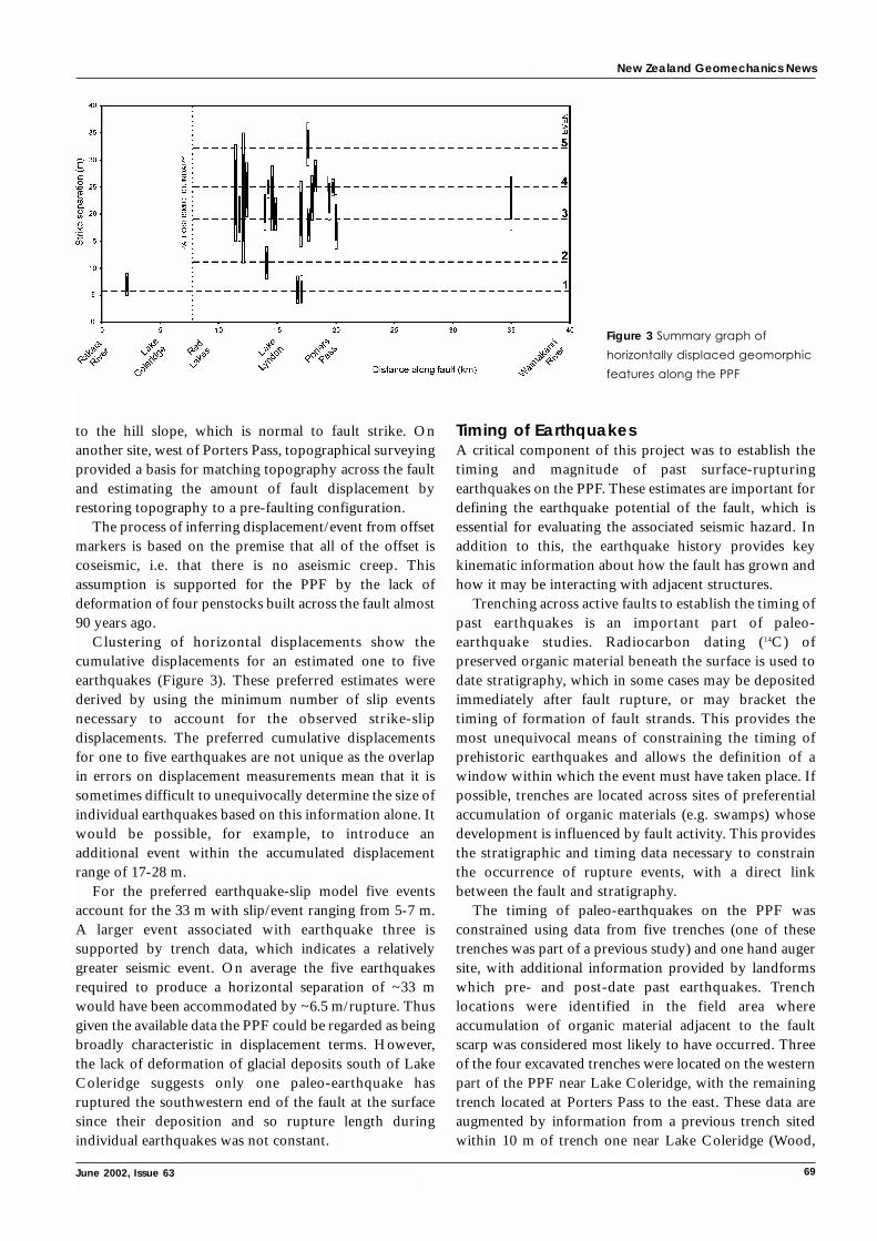
to the hill slope, which is normal to fault strike. Onanother site, west of Porters Pass, topographical surveyingprovided a basis for matching topography across the faultand estimating the amount of fault displacement byrestoring topography to a pre-faulting configuration.
The process of inferring displacement/event from offsetmarkers is based on the premise that all of the offset iscoseismic, i.e. that there is no aseismic creep. Thisassumption is supported for the PPF by the lack ofdeformation of four penstocks built across the fault almost90 years ago.
Clustering of horizontal displacements show thecumulative displacements for an estimated one to fiveearthquakes (Figure 3). These preferred estimates werederived by using the minimum number of slip eventsnecessary to account for the observed strike-slipdisplacements. The preferred cumulative displacementsfor one to five earthquakes are not unique as the overlapin errors on displacement measurements mean that it issometimes difficult to unequivocally determine the size ofindividual earthquakes based on this information alone. Itwould be possible, for example, to introduce anadditional event within the accumulated displacementrange of 17-28 m.
For the preferred earthquake-slip model five eventsaccount for the 33 m with slip/event ranging from 5-7 m.A larger event associated with earthquake three issupported by trench data, which indicates a relativelygreater seismic event. On average the five earthquakesrequired to produce a horizontal separation of ~33 mwould have been accommodated by ~6.5 m/rupture. Thusgiven the available data the PPF could be regarded as beingbroadly characteristic in displacement terms. However,the lack of deformation of glacial deposits south of LakeColeridge suggests only one paleo-earthquake hasruptured the southwestern end of the fault at the surfacesince their deposition and so rupture length duringindividual earthquakes was not constant.
Timing of EarthquakesA critical component of this project was to establish thetiming and magnitude of past surface-rupturingearthquakes on the PPF. These estimates are important fordefining the earthquake potential of the fault, which isessential for evaluating the associated seismic hazard. Inaddition to this, the earthquake history provides keykinematic information about how the fault has grown andhow it may be interacting with adjacent structures.
Trenching across active faults to establish the timing ofpast earthquakes is an important part of paleo-earthquake studies. Radiocarbon dating (14C) ofpreserved organic material beneath the surface is used todate stratigraphy, which in some cases may be depositedimmediately after fault rupture, or may bracket thetiming of formation of fault strands. This provides themost unequivocal means of constraining the timing ofprehistoric earthquakes and allows the definition of awindow within which the event must have taken place. Ifpossible, trenches are located across sites of preferentialaccumulation of organic materials (e.g. swamps) whosedevelopment is influenced by fault activity. This providesthe stratigraphic and timing data necessary to constrainthe occurrence of rupture events, with a direct linkbetween the fault and stratigraphy.
The timing of paleo-earthquakes on the PPF wasconstrained using data from five trenches (one of thesetrenches was part of a previous study) and one hand augersite, with additional information provided by landformswhich pre- and post-date past earthquakes. Trenchlocations were identified in the field area whereaccumulation of organic material adjacent to the faultscarp was considered most likely to have occurred. Threeof the four excavated trenches were located on the westernpart of the PPF near Lake Coleridge, with the remainingtrench located at Porters Pass to the east. These data areaugmented by information from a previous trench sitedwithin 10 m of trench one near Lake Coleridge (Wood,
New Zealand Geomechanics News
June 2002, Issue 63 69
Figure 3 Summary graph of
horizontally displaced geomorphic
features along the PPF

New Zealand Geomechanics News
70 Newsletter of the New Zealand Geotechnical Society Inc.
Paterson & Howard 1989) and from a road batter atPorters Pass (Cowan, Nicol & Tonkin 1996).
The most unequivocal data was obtained in the trench atPorters Pass where interpretation of data indicates that atleast four and as many as six earthquakes have occurredduring the Holocene on the PPF. The timing data from theother localities shows that the proposed timing of theseevents is consistent between the different data sets (Figure 4).
Data for events one, two and four (event one being themost recent) are from more than one location and haveenabled the timing of earthquakes to be constrained in theeast of the field area near Porters Pass. From oldest tomost recent, preferred ages for fault rupture in years B.P.are 8500 ± 200, 5300 ± 700, 2500 ± 200 and 1000 ± 100.Additional events may have occurred at 6200 ± 500 and500 ± 100 years B.P. The ambiguous nature of trench fourdata regarding the most recent event horizon, togetherwith the lack of evidence from other sites means that thiscannot be confirmed. In the west of the field area, nearLake Coleridge, only the 2500 ± 200 event could beidentified, supporting the notion that the PPF does notalways rupture along its full length. As a result,displacement and timing data give slip rates in the westand east of 0.3-0.9 mm/yr and 2.9-3.7 mm/yr respectively.
Recurrence interval is derived by estimating the averagetime between earthquakes, and ranges from 1700-2500years in the east and ≥7500 years in the west.
Hazard Posed by PPFThe hazard posed by the PPF cannot be determined bytrenching as this does not provide sufficient data on themagnitude of paleo-earthquakes. Because the PPF has notexperienced historic coseismic ruptures, the magnitude ofpast (prehistoric) earthquakes is most accuratelydetermined by using field data for the single-eventdisplacements and rupture lengths of these events.Estimates of earthquake magnitude rely on the ability tocorrelate fault geometry with earthquake magnitude andare useful for determining past magnitude of the PPFbecause they do not rely on historical seismicity.
The moment magnitude scale (Kanamori 1997; Hanks& Kanamori 1979) is useful for determining the energyrelease of an earthquake based upon paleoseismic data.This scale incorporates the seismic moment (Mo) whichrepresents the energy released at the source. Wells andCoppersmith (1994) also correlate fault-rupture lengthand area with magnitude using empirical relationshipsfrom a worldwide historical earthquake database. Todetermine the magnitude of a PPF earthquake, both ofthese models were used with rupture scenarios thatcompared a rupture along only part of the PPF (32 kmlength) compared with a full rupture along this fault andthe PPAFZ, a distance of 100 km. A range of averagecoseismic displacement of 4-8 m was used in order toaccount for the distribution of displacement data. An
Figure 4 Summary of earthquake timing data along the PPF. Vertical lines indicate possible age range of
earthquake event. Preferred ages (shaded boxes) derived by considering all data on table. Horizontal lines
show approximate earthquake timing. Question marks denote timing of possible earthquakes.

New Zealand Geomechanics News
June 2002, Issue 63 71
average of rupture models with different rupture lengthscenarios suggests that magnitudes on the PPF wouldproduce a M6.9 to M7.7 earthquake.
Conclusions• The PPF is part of the PPAFZ and is an active fault
within 60 km of the population centre of Christchurch.• The horizontal offset of geomorphic features across the
PPF were measured using a tape and survey equipment.Clustering of these data suggest that earthquakes on thisfault produce 5-7 m of displacement.
• Timing of past earthquakes was determined primarily byradiocarbon dating organic horizons in four trenchesexcavated across the fault. At least four events in the last10,000 years could be identified on the eastern part ofthe PPF giving an earthquake recurrence interval of1700-2500 years.
• Slip rates on this part of the PPF are as much as 3.7mm/yr, however the identification of only a singleHolocene event on the west of the PPF gives a lower sliprate of 0.9 mm/yr. This suggests that the fault issegmented and does not rupture along its full lengthduring an earthquake.
• The expected magnitude on the PPF has been derivedusing empirical models which rely on fault geometryand movement rates and is between M6.9 and 7.7.
• The fault has the potential to cause significant damageand loss of life in the region.
ReferencesBurrows, C. J. 1975, “A 500-year-old Landslide in the
Acheron River Valley, Canterbury”, New ZealandJournal of Geology and Geophysics, 18(2), pp. 357-360.
Cowan, H. A. 1992, Structure, Seismicity and Tectonics ofthe Porters Pass-Amberley Fault Zone, NorthCanterbury, New Zealand, unpublished PhD thesis,University of Canterbury, Christchurch, New Zealand.
Cowan, H., Nicol, A. & Tonkin, P. 1996, “A Comparisonof Historical and Paleoseismicity in a Newly FormedFault Zone and a Mature Fault Zone, NorthCanterbury, New Zealand”, Journal of GeophysicalResearch, 101, pp. 6021-6036.
Coyle, S. 1988, The Porter’s Pass Fault, unpublished MScthesis, University of Canterbury, Christchurch, NewZealand.
DeMets, C., Gordon, R. G., Argus, D. F. & Stein, S. 1994,“Effect of Recent Revisions to the Geomagnetic TimeScale on Estimates of Current Plate Motions”,Geophysical Research Letters, 21, pp. 2191-2194.
Hanks, T. C. & Kanamori, H. 1979, “A MomentMagnitude Scale”, Journal of Geophysical Research, 84,pp. 2348-2350.
Howard, M. E. 2001, Holocene Surface-RupturingEarthquakes Along the Porters Pass Fault, unpublishedMSc thesis, University of Canterbury, Christchurch,New Zealand.
Kanamori, H. 1977, “The Energy Release in GreatEarthquakes”, Journal of Geophysical Research, 82, pp.2981-2987.
Nicol, A., Howard, M., Campbell, J. & Pettinga, J. 2001,Paleoearthquakes on the Porters Pass Fault, EQCReport 2001/97.
Norris, R. J., Koons, P. O. & Cooper, A. F. 1990, “TheObliquely-Convergent Plate Boundary in the SouthIsland of New Zealand: Implications for AncientCollision Zones”, Journal of Structural Geology, 12,5/6, pp. 715-725.
Pettinga, J. R. & Wise, D. U. 1994, “Paleostress Adjacentto the Alpine Fault: Broader Implications, South Island,New Zealand”, Journal of Geophysical Research, 99, pp.2727-2736.
Wells, D. L & Coppersmith, K. J. 1994, “New EmpiricalRelationships Among Magnitude, Rupture Length,Rupture Width, Rupture Area, and SurfaceDisplacement”, Bulletin of the Seismological Society ofAmerica, 84, 4, pp. 974-1002.
Wood, P. R., Paterson, B. R. & Howard, G. 1989, AnEvaluation of Foundation Geology and SeismotectonicHazards of the Lake Coleridge Power Scheme, NZGeological Survey Contract Report 1989/3.
AcknowledgmentsThe New Zealand Earthquake Commission (EQC), theInstitute of Geological and Nuclear Sciences (GNS) and aUniversity of Canterbury Masters Scholarship havefunded research. Assistance to attend the Fifth YoungGeotechnical Professionals Conference from EQC,NZGS and URS are also gratefully acknowledged.
Matt HowardURS New Zealand LtdPO Box 4479ChristchurchEmail: [email protected]

New Zealand Geomechanics News
72 Newsletter of the New Zealand Geotechnical Society Inc.
IntroductionExcavations in Auckland clays reveal that the upper part ofthe soil profile, up to depths of a metre or so but usuallyless, is fissured. Photographs from a site on the NorthShore, kindly supplied by Mr Bill Thompson, are shown inFigures 1 and 2. One possible explanation for the fissures isthe cracking of the ground surface that occurs in thesummer. This is reasonable for the vertical and near verticalfissures in the photographs but does not explain thepresence of the low angle fissures also apparent. Swelling inwet periods following the cracking has been suggested as apossible explanation for these. After the cracks are formed,debris falls into the cracks, or rootlets intrude into them. Inthe wet season the clay absorbs water and swells, but theswelling is restrained in those cracks which now containdebris. This process can produce passive failure of the claywith consequent low-angle failure surfaces. This sequencewill be repeated from year to year and over a period of timeclay structures such as those shown in Figures 1 and 2 are
produced. To my knowledge this mechanism was firstproposed by Terzaghi (1929) for explaining large pressuresagainst walls retaining clay, and is also offered byTschebotarioff (1973). Pender (1996) presents data showingextension failure of Auckland clay on a low-angle failuresurface induced during one-dimensional swelling in alaboratory Ko triaxial cell; a test intended to replicate themechanism proposed by Terzaghi and Tschebotarioff forthe formation of the low angle fissures such as those inFigures 1 and 2.
The purpose of this short paper is to consider theimplications of fissures in the upper part of the Aucklandclay profile for the design of shallow footings and polewall foundations. Prior to shallow footing constructionthe fissured zone, or the most severely fissured upper part,is likely to be removed as part of the site preparation. Thusfoundations for pole walls are the shallow foundationsituation for which the presence of the fissures might bemost significant.
Fissuring in Auckland Residual Clays and the Capacity of Shallow Foundations – II1
M. J. Pender, Department of Civil and Environmental Engineering, University of Auckland
Figure 1 Fissured clay at the site of a pole retaining wall
in Takapuna. Height of excavated face about 1.2 m.
Figure 2 Close-up of the face shown in Figure 1.
Note the low angle fissures and the rootlets on
some of the exposed surfaces.

New Zealand Geomechanics News
June 2002, Issue 63 73
Effect of Specimen Size on the ShearStrength of Fissured SoilHow do we estimate the undrained shear strength of clay?A common method is to use an in situ vane shear test. Thecommon vane configuration is such that the vane height issubstantially less than 100 mm and the diameter is abouthalf this. From Figures 1 and 2 it is apparent that the vanesize is small in relation to the spacing between the fissures.This raises the question of how representative is the vaneshear strength of the actual shear strength of the soil mass.The shear strength along the fissures is expected to be lessthan that of the intact material between them. Thus theshear strength of a soil mass with fissures would be lessthan that of the material between the fissures and a certainminimum volume of soil would need to be tested beforethe actual field shear strength of the soil mass could beestimated. In other words, the shear strength of the soilmass is controlled more by the pattern of fissures than thestrength of the intact material between, in just the sameway as the strength of a jointed rock mass is likely to becontrolled by the joint system. The question which thenarises is what is the actual shear strength of the mass offissured soil?
Although the strength of large volumes of soil is notoften investigated, examples are given by Bishop and Little(1967) and Marsland and Butler (1967). Each of thesepapers presents some data on the shear strength of fissuredLondon clay and each concludes that larger specimensindicate a smaller shear strength, although the presence ofa fissure at an unfavourable orientation in a smallspecimen can give a small shear strength value. Data fromthe Bishop and Little paper are reproduced in Figure 3 anddata from Marsland and Butler in Figure 4.
Figure 3 Comparison between values of undrained shear
strength determined by field testing on ‘large’ volumes of
soil and those determined from 76 mm tall by 38 mm
diameter laboratory specimens (reproduced from Bishop
and Little). Normal stresses for the direct shear tests 45 to
115 kPa. (1 ft ≈ 305 mm, 1 inch ≈ 25.4 mm, 1 lb/in2 ≈ 6.9 kPa,
1 lb/ft2 ≈ 0.05 kPa)
Figure 4 Comparison of the
compressive strength values
(≈ 2su) determined from
unconsolidated undrained (UU)
triaxial testing on 38 mm and
100 mm diameter specimens of
fissured and unfissured clays
(after Marsland and Butler 1967).
Cell pressures for the UU triaxial
tests were approximately equal
to the overburden pressure at
the depths from which the
samples were taken.

Additional information is available on the strength of coalwhich has closely spaced fissures (known as cleat in themining industry). In Figure 5, data from compressivestrength tests on cuboidal blocks of coal in anunderground mine in South Africa are reproduced fromBieniawski (1968).
These test results lead to similar conclusions to thosederived from the tests in clay, namely that joints andfissures make an important contribution to the strength ofthe material and some minimum specimen size is requiredbefore the shear strength available in the field can bedetermined. In the case of the Auckland clays, this dataleads to the conclusion that, in the fissured zone, the actualshear strength of the soil mass is expected to be less,perhaps considerably less, than that determined by thevane (or a cone penetration test or by taking samples andtrimming laboratory test specimens of usual sizes).
London clay, a heavily overconsolidated soil, is verydifferent from Auckland residual clay, formed in situ byweathering from the Waitemata group sandstones andsiltstones. Both of these are very different from coal in anunderground mine. Nevertheless the conclusion fromFigures 3 to 5 is that the presence of joints and fissuresmeans there is a size effect on the shear strength of thematerial regardless of the mode of formation. Similarly thestrength of fissured Auckland residual clay will be sizedependent and so the vane shear strength is more likely tobe an upper limit to the shear strength rather than a valuerelevant to foundation design. Additional informationabout size effects on the strength properties of soil is givenby Bonala and Reddi (1999).
Shallow Foundations in Fissured ClaysThe undersides of shallow foundations are typicallyestablished 300 to 600 mm beneath the surface of the
cleared ground surface at the building site. This means thatpart of the fissured soil is removed in the general sitepreparation process and possibly more when theindividual footing positions are prepared. Neverthelessthere may still be some fissured soil beneath thefoundation. In this section we consider briefly thesignificance of this.
Figure 6a has the standard mechanism associated withbearing capacity failure, the geometry of which dependson the angle of shearing resistance of the soil. For shortterm bearing failure the undrained shear strength, su,controls the maximum possible pressure and the linearsegments of the mechanism all meet the horizontal surfaceat 45 degrees. For drained behaviour the angle of shearingresistance, φ, controls the bearing capacity and the outertriangular regions of the mechanism meet the horizontalsurface at an angle of 45 – φ/2 degrees. A possibleconsequence of the fissures is a drained failure mechanismdefined by fissures that happen to be oriented along theparts of the failure mechanism in Figure 6a. The smoothappearance of the fissure surfaces in the field suggests lowshear strength. However, they are not planar so thegeometrical ‘roughness’ will also contribute to the shearresistance. Conventional drained bearing capacitycalculations with an angle of shearing resistance of about20 degrees (say 10 degrees for the smooth surface and anadditional 10 degrees from the surface geometry), indicatea drained bearing capacity for a shallow foundation aboutthe same as the undrained bearing capacity for a soilhaving an undrained shear strength of about 25 to 30 kPa.This suggests that the short term bearing capacity of ashallow foundation could be controlled by drainedshearing along fissures, rather than undrained shearingthrough the clay, if the actual value of the undrained shearstrength was greater than about 25 to 30 kPa. For this to
New Zealand Geomechanics News
74 Newsletter of the New Zealand Geotechnical Society Inc.
Figure 5 Effect of specimen
size on the compressive
strength of cuboidal blocks
of coal with closely spaced
discontinuities (after
Bieniawski 1968).

New Zealand Geomechanics News
June 2002, Issue 63 75
occur the fissuring would need to extend for depths ofabout one footing width or more below the foundationand the orientation of the fissures would need to be suchthat the shape of the bearing capacity mechanism could bematched, at least roughly, by a number of fissuresegments.
Another possibility is that the near vertical fissuresdominate, as illustrated in Figure 6b, and the foundationload is simply carried down through vertical ‘columns’ ofclay to the underlying unfissured material.
Lateral Strength of Pole FoundationsEmbedded in ClayA convenient approach to estimation of the short-termultimate lateral strength of piles embedded in clay is thatproposed by Broms (1964). The only soil propertyrequired is the undrained shear strength, su. Broms explainsthat there are two limiting cases. First the so-called shortpole case where the lateral strength is limited by the soilstrength and the long pile case where the lateral strength islimited by the moment capacity of the pile section. (Notethe terminology: the short case refers to pole and the longcase to a pile.)
The lateral strength of the short pole is:
Hult = 9suDs [√(L+2f +fo)2+(L-fo)
2- (L+2f + fo)] 1
The depth beneath the ground surface at which themaximum moment occurs is given by:
gc = fo+ 2
The lateral strength of a long pile is:
Hult = 9suDs [√(f +fo)2+ - (f + fo)] 3
The location of the maximum moment, Mult, for a longpile, is as given in equation 2. Beneath this point furtherpile shaft length is required to sustain the ultimatemoment of the pile section. Thus the minimum pile shaftlength required to develop the lateral strength given inequation 3 is:
Llong– pile = fo+ +2√ 4
where:Hult ultimate lateral resistance of a pile (kN)Mult ultimate moment capacity of the pile shaft (kNm)L length of the embedded part of the pile shaft (m)Ds diameter of the pile shaft embedment (m)fo length of pile shaft near the ground surface (m)
assumed to be unsupported in cohesive soilf the distance above the ground surface at (m)
which the horizontal shear is appliedsu undrained shear strength of the clay in (kPa)
which the pile is embeddedgc distance down the pile shaft from the ground (m)
surface at which the maximum moment occursLlong_pile minimum pile shaft length required (m)
to develop the long pile lateral strength
Further information on these two cases is given byPender (1997).
Table 1 gives the calculated ultimate lateral strength ofpoles embedded 1.2 m. Both the short pole and long pilevalues given by equations 1 and 3 are tabulated for variousvalues of the undrained shear strength of the ground inwhich the poles are embedded. The lower limit used for su,25 kPa, is well below the vane shear strength found forAuckland residual clays. Not surprisingly the short polestrength increases as the undrained shear strength of theclay increases, but the lateral strength for the long pilecase, being controlled by the ultimate moment capacity ofthe pile shaft, is found to be only slightly dependent on theundrained shear strength of the soil. The results in Table 1are based on the assumption that the concrete in which thepile shafts are embedded contributes nothing to themoment capacity of the section because of cracking. The
Figure 6 Bearing capacity of shallow foundations:
a) the standard ultimate strength mechanism
b) ‘column’ action in soil with vertical fissures
2Mult
9suDs
Hult
9suDs
Hult
9suDs
Mult
9suDs
A
B

concrete does contribute to lateral bearing though, so, Ds,the diameter of the embedded part, occurs in equations 1and 3. The embedded length used for the short polecalculations in Table 1 is 1.2 m. The minimum embeddedlength for the long pile case, from equation 4, is less thanthis for all but the case with an su value of 25 kPa when itis about 1.55 m.
The explanation of this result is as follows. For theshort pole the shaft is considered to have unlimitedmoment capacity and then, as indicated in equation 1, thelateral strength depends on the undrained shear strengthof the clay and the depth of embedment, L. In the longpile case the bending moment in the pile shaft increases asthe lateral load applied to the pile is increased. Themaximum moment reaches the section capacity before theshear strength of the soil is fully mobilised. Equation 3shows that the lateral strength is a function of the shearstrength of the soil and the moment capacity of the pilesection, but not on the embedment depth (assuming thatthe embedment depth is sufficient for the pile to be ableto sustain the section ultimate moment). In the design ofpole foundations both the short and long pile capacitiesare evaluated, and the smallest value becomes the designvalue. It is apparent from Table 1 that, except for thelowest clay strength, it is the long pile strength which is critical.
Repeating the calculations for 0.3 m diameter polesinstalled to a depth of 2.4 m in a 0.45 m diameterembedment leads to the same conclusion.
Another way of considering the above result is to makeMult the subject of equation 3. That is, find the momentcapacity required of the pile section for a given Hult.Rearranging equation 3 gives:
Mult =2
+Hult (f + fo) 5
This shows that the required moment capacity of the pilesection depends on two quantities. One can then see thatthe undrained shear strength of the soil has a small effecton the required moment capacity of the pile section whenHult (f + fo) > H2
ult/18suDs. It is also apparent that thesignificance of the shear strength of the soil decreases as f,the distance above the soil surface at which the horizontalload is applied, increases.
Ultimate Limit State ConsiderationsIt is worth considering how equations 1 and 3 are used in anultimate limit state design context. There are two quitedifferent approaches to ultimate limit state design; thepartial Factor of Safety approach used in the Eurocodes andthe LRFD (Load and Resistance Factored Design) used inNZ and North America (cf Pender (2000)). Applying thepartial factor of safety approach to equation 3, one dividesthe undrained shear strength of the soil by a partial factor ofsafety (a number greater than unity) and similarly calculatesthe ultimate moment capacity of the pile section using areduced ultimate bending stress. Equation 3 then gives adesign lateral strength for a long pile.
Using the LRFD approach things are initially not quiteso clear. We apply a strength reduction factor (a numberless than unity) to the Hult calculated with equation 1 to getthe design lateral strength of the pile (note that, in keepingwith the LRFD approach, this is applied to Hult and not su
even if the end result would be the same). Likewise wemight expect to apply a similar factor to the Hult calculatedwith equation 3. However, in this case it is the momentcapacity of the pile section, buried on the right hand side ofthe equation, which controls the ultimate lateral strength.A possible way out of this difficulty is to use equation 5 tofind the moment capacity required of the pile section for agiven factored horizontal load. The strength reductionfactor for a timber pile is about 0.8 (note that this isadditional to the load duration factor of 0.82, the steamingfactor of 0.9 and the shaving factor of 0.9 already applied).Thus I propose tentatively that one uses equation 3 withthe pole strength reduction factor applied to the ultimatemoment capacity of the pole section, that is substituteΦpoleMult for Mult, and apply no strength reduction factordirectly to Hult (in effect using equation 5 and thenrearranging to get Hult). This acknowledges that the criticalfactor in controlling the lateral capacity given by equation3 is Mult rather than su. In Table 2 these suggestions areapplied to the results in Table 1, notice that now the shortpole case is critical for the first two values of su.
ConclusionWe have two conclusions:
First, the undersides of shallow foundations aretypically established 300 to 600 mm beneath the surface of
New Zealand Geomechanics News
76 Newsletter of the New Zealand Geotechnical Society Inc.
Table 1 Comparison
of the ultimate lateral
strengths of short and
long piles in clay
Hult
18suDs

the cleared ground surface at the building site. This meansthat part of the fissured soil is removed in the sitepreparation and possibly more when the individualfooting positions are prepared. If the depth of fissuringbeneath the shallow foundation is less than the width, thenthe load is likely to be carried directly down to theunderlying unfissured clay by ‘column’ action.
Second, we come to the interesting, and unexpected,conclusion that the ultimate lateral strength of a pileembedded in clay is not sensitive to the shear strength ofthe clay if the long pile case, rather than the short polecase, controls the lateral capacity. In reaching thisconclusion the concrete in which the pile is embedded wasassumed to contribute nothing to the moment capacity ofthe pile because of cracking. It seems then, that theconcerns expressed at the beginning of this paper aboutestimating the actual value of the undrained shear strengthof the fissured soil in which the pole is embedded may notbe of great consequence if the long pile case controls.
AcknowledgmentsDrs Richard Fenwick and Richard Hunt, of theDepartment of Civil and Environmental Engineering at theUniversity of Auckland, provided some helpful commentson aspects of capacity of timber piles. In addition BrianWilson and Tony Synge, consulting engineers and membersof the Structural Engineering Society, have provided mewith helpful insights into pole foundation design.
ReferencesBieniawski, Z. T. 1968, “The Effect of Specimen Size on
Compressive Strength of Coal”, International Journalof Rock Mechanics & Mining Science, Vol. 5, No. 4, pp.325-335.
Bishop, A. W. & Little, A. L. 1967, “The Influence of theSize and Orientation of the Sample on the ApparentShear Strength of London Clay at Maldon, Essex”,Proc. of the Geotechnical Conference on Shear StrengthProperties of Natural Soils and Rocks, Oslo, 1967,Norwegian Geotechnical Institute, Vol. 1, pp. 89-96.
Bonala, M. V. S. & Reddi, L. N. 1999, “FractalRepresentation of Soil Cohesion”, Journal of
Geotechnical and Geoenvironmental Engineering, Vol.125, No. 10, pp. 901-904.
Broms, B. B. 1964, “Lateral Resistance of Piles inCohesive Soils”, Proc. ASCE, Jnl. Soil Mech. andFound. Div., Vol. 90 SM3, pp. 27-63.
Marsland, A. & Butler, M. E. 1967, “StrengthMeasurements on Stiff Fissured Barton Clay fromFawley (Hampshire)”, Proc. of the GeotechnicalConference on Shear Strength Properties of NaturalSoils and Rocks, Oslo, 1967, Norwegian GeotechnicalInstitute, Vol. 1, pp. 139-145.
Pender, M. J. 1996, “Aspects of the Geotechnical Propertiesof Some NZ Materials”, Proceedings 7th Australia -NZConference on Geomechanics, Adelaide, pp. 21-39.
Pender, M. J. 1997, “Ultimate Lateral Capacity of PilesEmbedded in Soil”, Journal of the Structural EngineeringSociety of New Zealand, Vol. 10, No. 2, pp. 53-60.
Pender, M. J. 2000, “Ultimate Limit State Design ofFoundations”, Notes for the NZ Geotechnical SocietyShort Course, Christchurch and Auckland, August,Chapter 8.
Terzaghi, K. 1929, “The Mechanics of Shear Failures onClay Slopes and the Creep of Retaining Walls”, PublicRoads, Vol. 10, No. 10, pp. 177-192.
Tschebotarioff, G. P. 1973, Foundations, Retaining andEarth Structures, McGraw-Hill, p. 386.
1 This is a development of a paper having a similar title and
contents published in the SESOC Journal for December 2001
(Journal of the Structural Engineering Society of New
Zealand, 14(2), 35-41)
2 NZS 3603:1993 stipulates that permanent loads, and it
mentions soil pressures specifically in this category, require
a load duration factor of 0.6. It also states that for medium
term loads, duration between 6 hours and five years, the
load duration factor is 0.8. The time frame associated with
the short-term capacity in the geotechnical context is likely
to be towards the beginning of the medium load duration in
the timber code. Thus a load duration factor of 0.8 is used in
the calculations for Tables 1 and 2.
New Zealand Geomechanics News
June 2002, Issue 63 77
Table 2 Comparison
of the ultimate and
design lateral
strengths of short
and long piles
in clay

New Zealand Geomechanics News
78 Newsletter of the New Zealand Geotechnical Society Inc.
Earthtech Consulting LtdPO Box 721, PukekohePhone: 09 2383 669Fax: 09 2328 818Email: [email protected] Contact: Philip Kelsey
Earthtech Consulting Ltd is a specialist engineeringpractice working in the fields of engineering geology,geotechnical engineering and hydrogeology. The companyis run by Philip Kelsey and Aidan Nelson.
Earthtech was formed in 1989 and initially workedprimarily on subdivisions in the Franklin District. Withtime Earthtech has enjoyed working on larger and morevaried projects in the Auckland area and beyond.
Landfill engineering has been a significant area ofspecial interest. Earthtech has been involved with landfillsite selection studies and specific site investigations in theAuckland, Waikato, Bay of Plenty and ManawatuRegions. One of the highlights has been the geotechnicaland hydrogeological investigations and hearing workassociated with the recently consented North WaikatoRegional Landfill at Hampton Downs.
Earthtech has also worked on a number of coastalengineering projects on the Coromandel. The Pauanui andWhitianga Canal Development projects have providedchallenges with respect to ground treatment forliquefaction, control of groundwater drawdown withrespect to adjacent aquifers, and a very attractive workingenvironment for fieldwork.
In addition to the above, Earthtech is also currentlyinvolved with roading, quarrying, and groundwater supplyprojects. The company also carries out peer review workfor a number of local authorities and private companies.
Our practice has a strong emphasis on fieldwork andwe consider that good solutions to difficult geotechnicaland hydrogeological problems are based on good sitecharacterisation.
COMPANY PROFILES
Earthtech Consulting Ltd, Auckland
The geosciences group at MWH includes people withskills in hydrology, engineering geology, geotechnical andfoundation engineering, dam and dam safety,contaminated site investigation and remediation. Thegroup has over 30 experts based in Whangarei, Auckland,Hamilton, Wellington, Palmerston North, Nelson,Christchurch and Dunedin.
MWH’s geotechnical engineering team provides a widerange of services and has been involved in the identification,assessment, investigation and construction supervision ofnumerous domestic and international projects since theearly 1930s. These projects include bridges, roading, canals,tunnels, dams, hydro-electric power schemes, irrigationschemes, water supply, mining schemes, landfill siting anddesign, and structure foundations.
The recent merger between Montgomery Watson andHarza Engineering (to form MWH) enhances our accessto the highest level of geotechnical expertise from UKand USA. Internationally, MWH is responsible for someof the largest dams in the world including concrete, rockand earthfill dams. This includes the 240 metre concretearch dam for the 3300 MW Ertan project in China andthe 200 metre rockfill/clay core dam for the San Roque inthe Phillipines.
In New Zealand, the geosciences group are activewithin the roading sector through numerous Transit andlocal authority projects including Hawkes BayExpressway in Napier, and PSMC support; the mineralextraction industry; clean and waste water projects; anddam schemes including Wilson’s Dam near Whangarei.
Montgomery Watson Harza (New Zealand) Ltd
MWH (New Zealand) LtdPO Box 89, HamiltonPhone: 07 839 9863Fax: 07 839 4234Email: [email protected]: Stuart Finlan

New Zealand Geomechanics News
June 2002, Issue 63 79
Career PathMy university life began in the engineering school wantingto become a mineral processing engineer. However findinggeology more interesting I changed degree courses andcompleted a BSc and MSc in Geology at AucklandUniversity. Between university degrees I spent a wonderfulsummer living in Waihi Beach working for Cyprus GoldNZ in their exploration division, investigating potentialgold sources in the Waitekauri Valley. Unfortunately Irealised the limited potential for exploration and mining inNew Zealand and not wanting to join my friends ‘acrossthe ditch’ changed my geology career path from miningand mineral exploration to engineering geology.
I joined the Beca Group of companies in 1992 workingin their soils laboratory during my Masters degree insteadof joining the newly introduced student loan scheme; amutually beneficial arrangement that allowed me to usethe laboratory equipment for the soils testing requirementin my Master’s thesis. On completion of the degree Ijoined Beca full time and became an interim laboratorymanager for nearly two years while a suitably qualifiedmanager was sought. Eventually I left this role aftertraining someone for this position in 1995. Since then Ihave worked as an engineering geologist for Beca based intheir Auckland office.
Recently I have been fortunate enough to reduce myhours at Beca to pursue other interests including cattlebreeding and farming in the Hokianga and Onewhero,being the financial administrator of a psychologicalpractice and assisting in the family engineering practice ongeotechnical/geologic issues.
Typical Work WeekMonday, Wednesday and Thursdays are normally spent atBeca writing reports, engineering geologic mapping,undertaking geotechnical analyses, reviewing logs andcores, mentoring/training a group of young engineeringgeologists and job management.
Tuesday and every second Saturday morning arenormally spent at Rojolie Clinic being a receptionist,reviewing financial performance of staff and thecompany, writing promotional documents, upgradingand implementing new administrative tools as requiredand spending time with accountants, lawyers andfinancial advisers.
Tuesday afternoons, Fridays and alternative weekendsare flexible days generally spent on one of the family farmsor family business, and when required catching up at Beca.Lately there have been more weekends off socialising thanfarming, due to a brother returning to NZ to manage theHokianga farm.
Highs and LowsI enjoy nearly all aspects of field work and analyses thatleads to engineering geologic assessment of an area or site.Particularly in new places and countries, where one’sgeologic interpretation skills are required most and whereone can get involved in other cultures. On a personal levelI have obtained a lot of satisfaction from engineers andclients seeing the value that myself and colleagues haveprovided when engineering geologic advice is used early intheir projects and frustration when they ask too late.
The RMA process has reduced enjoyment of projects asthey get stuck in legal or consultation battles.
AmbitionsPresently I am looking forward to becoming a mother andreducing my consulting hours. I am sure this new role willstretch my people and project management skills.
AdvicePlan jobs to the smallest feasible task and complete eachone before moving on.
The best advice I have received is to enjoy your workand personal life as much as possible. If not, get some goodcounselling.
MEMBER PROFILES
Susan Tilsley
OccupationSenior Engineering Geologist, Beca Carter Hollings and Ferner Ltd, Auckland Engineering Geologist, Tilsley Associates (part-time)Financial Administrator, Rojolie Clinic (part-time)Part-time farmer and cattle breeder

New Zealand Geomechanics News
80 Newsletter of the New Zealand Geotechnical Society Inc.
Route to the JobI come from a family of Engineers. My father, grandfatherand uncle were all in the profession, and I was proud tofollow in their footsteps. During my civil engineeringdegree at Auckland University, I was awarded a cadetshipwith Fletcher Construction, which gave me a valuablegrounding in large civil engineering works. Thanks to theproblems experienced on projects such as the Taurangaharbour bridge and the Waikato River diversion works atArapuni, I developed an interest in soil mechanics anddecided to pursue a career in geotechnical engineering. I have been employed by Foundation Engineering inAuckland since mid-1989, where I now co-manage a largeteam and investigate and report on a wide range of landdevelopment and building projects.
Typical DayBecause my work is so varied, both in type and scale, therereally is no such thing as a typical day. During an averageweek, I spend the equivalent of at least one day attendingmeetings and carrying out site inspections. The rest of mytime is spent reviewing investigative data, writing reports,working on designs and corresponding with clients. As aSenior Engineer in the Consultancy I am also responsiblefor reviewing technical reports and designs prepared byjunior engineers.
Highs/LowsHigh points of my job include being able to bring to life aclient’s vision, especially when a site has challenginggeotechnical problems. Being in a medium-sized
consultancy, and being directly responsible for thegeotechnical aspects of an entire project, I enjoy thesatisfaction of managing a job from conception tocompletion. This would probably not be the case in a largeconsultancy. Low points include dealing with difficultclients who employ me for my expertise but still think theyknow best! Another is managing a very large workload,trying to juggle a hundred things at once and please all myclients, who often have unrealistic timeframes.
AmbitionsOne of the most crucial lessons I have learnt in recentyears has been the importance of geological models toassist in solving complex geotechnical problems. I wouldtherefore like to undertake post graduate studies in fieldssuch as engineering geology and landslide engineering. Ona business level, as a Director I hope to grow FoundationEngineering both within Auckland and further afield.
AdviceFor a young person studying engineering I wouldstrongly recommend post graduate study in bothgeomechanics and engineering geology. This would beinvaluable for developing the appropriate technical skillsfor a successful future in geotechnical engineering. It isalso vital in our field to have good verbal and writtencommunication skills. Irrespective of your age orexperience, every site offers new challenges. There isalways something new to learn and even for SeniorEngineers, nothing beats putting on your boots andgetting your hands dirty once in a while.
Peter Bosselmann
Age 36
OccupationSenior Geotechnical Engineer, Foundation Engineering

New Zealand Geomechanics News
June 2002, Issue 63 81
The quotation is from an ‘essay’ written by Karl Terzaghi in 1924 in Istanbul. It is referred to in Goodman’s biographyof Terzaghi (“The Engineer as Artist”), and printed in full in the issue of Geotechnique dedicated to Terzaghi’s memoryshortly after his death – March 1964 (Vol. 14, No. 1).
It seems often to be the case that those who make an outstanding contribution in one particular technical field alsohave a very wide knowledge and interest in other areas of human existence. It was certainly the case with Terzaghi, andhe ‘philosophised’ much about the nature of human existence and how to make life meaningful. The essay is worthreading in full, along with other quotes of Terzaghi which appear in the same edition of Geotechnique.
LAURIE’S BRAIN TEASER
Answer to Brain Teaser No. 5 (December, 2001)
INDEPENDENT CIVIL LABORATORY LTDRoading + Foundations + Subdivisions
• On call service of Nuclear Density tests of Soil and Aggregate compaction
• IANZ approved Signatory in Nuclear Density Test NZS 4407:1991 Tests 4.2.1 & 2
• 9 years local testing experience
• A service for the northern half of the South Island. Includes all of the West Coast.
Consultants: Know that your compaction testing can be carried out when youwant. Preliminary results can be phoned in from on site. Site Supervision of fillingavailable.
Contractors: Fax or email thetesting requirements of yourcontract for pricing. Friendlyadvice available.
Paul Yellowlees – Laboratory ManagerPh: 03 374 5337 Fax: 03 374 5424Mobile: 021 613 703Email: [email protected]

New Zealand Geomechanics News
82 Newsletter of the New Zealand Geotechnical Society Inc.
“Steal the cream and leave the milk, that’s the way isn’t itJon? Arrr, there’d not be much left over for the rest of usthen? Why don’t you give me them boots now?” (bestpronounced in one’s best Dougal/Father Ted accent).
Such was my early morning greeting from big James, aburly fifty-something labourer with a formidable chestlike a mountain gorilla with implants. We were workingon the N4, a main route crossing Ireland from Sligo on thewest coast to Dublin on the east. Not that we were locatednear either place, or any place. In fact, the best sense oflocation one could gather was from the adjacent RiverShannon, which throughout winter frequently caused thesite to look like a prime rainbow trout spot.
James as it turns out, was from the town up the road andhad been for the last fifty-something years. He couldn’tunderstand why some smart-arse foreign lad like myselfshould be given brand spanking new padded safety jacket,new boots, new hard-hat etc. I had to regularly explain tohim that it was in the contract, and that it was also in thecontract that if he didn’t wear his old hard-hat, worn safetyjacket and grubby steel caps then he might be approachingretirement. Of course my considerable flexing ofcontractual muscle and three syllable words failed toimpress him in the slightest, usually to be greeted with ahighly creative monologue of profanity, blasphemy and theodd adjective. Not one to be outdone by an old man, Iinformed the Contractor that the transition piles (withreducing embedment into peat to make a smooth settlement
transition) could not be cut down with the hydrauliccropper due to risk of pile uplift. The next morning Jameswas out there with concrete saw and sledgehammer,sweating and cursing me with every swing at the piles.
The project consisted of rebuilding the approachembankments to a small bridge in the middle of a peat bogwith piled embankments and basal reinforcement. Themagnitude and rate of settlement was rather incredibleconsidering the light loads (embankment height less than1.5 m), with over one metre of settlement since 1976. Afterexcavation of one half of the road, at least eight previousroad surfaces were easily visible which obviously amountedto an ongoing maintenance problem for the local authority.
We had our own problems – it can really rain in Ireland.There was talk on the TV News of it being the wettestwinter in Central Ireland for fifty years, which waswonderful news. We regularly had to pump over 800 l/s,which is rather substantial for a miserable little roading job.Of course the overflowing lakes up the hill didn’t help toomuch either. The Contractor’s poor harassed Site Managerwould come to me with a pale glum face after doing battlewith the Shannon:“How’s the water doing then, Mick?”“CENSORED – don’t talk to me about themCENSORED pumps. I’ve every spare pump in Ireland onthe job, and half the CENSORED pumps from Europecoming.”
I quickly learnt to respond to such statements with abland “Oh right then.”
Of course the predictable outcome of such tamperingwith the environment came to pass. A letter was receivedfrom a PAP (or Project Affected Person) who owned anadjacent field, to the effect that we were causing theflooding of his land. After carefully considering how thiscould be the case when we were pumping 800 l/s from hisland, I passed the public relations aspects to the Client andwondered if we should actually send the fellow a bill fordewatering. I could see the next event, when in summerwe would somehow be responsible for ruining hisindigenous fishery rights on the same bit of land.
And so after three months of eagerly watching men stickbits of concrete into the ground, it was time to go and trymy hand in Australia. My overall conclusion is that theIrish Potato Famine of the late 19th century as a trigger formass emigration was probably just a politically correct wayof saying the weather stinks. Mind you, they brew fantasticstout, make a good pie and produce a fine bit of trout.
FOREIGN CORRESPONDENT
Steal the Cream and Leave the MilkJon Sickling, Sinclair Knight Merz, Melbourne
Problems with the control of moisture content

New Zealand Geomechanics News
June 2001, Issue 61 83
PHOTO COMPETIT ION 2002
Where did I parkthat digger again?
Awarded First PlaceSam Brindle, Harrison Grierson Consultants Ltd
Graham SaltTonkin & Taylor Ltd, Dunedin
(“I could use that $200 for the panelbeater’s bill”)
Day 1 on the Big Project
Neil Crampton Pattle Delamore Partners Ltd
Hospital pass tothe offsider

New Zealand Geomechanics News
84 Newsletter of the New Zealand Geotechnical Society Inc.
Gordon Stevens,Maccaferri
Nose dive
Craig Davidson, Meritec
House caught with foundations down
Note: The photo is from a NON Meritec job, observed while drivingthe Auckland streets. Staff advised builders of the danger andcontacted the Council.
Peter Geddes,Hawthorn Geddes
Engineers and Architects
Roadingcompaction in Northland has come a
long way

New Zealand Geomechanics News
June 2002, Issue 63 85
Have you ever wondered what sort of character becomesa Geotechnical Engineer or Engineering Geologist? Dowe think of ourselves as individuals with distinctlydifferent character traits or is there some consistentthread? Maybe we are all cut from the same cloth? Maybewe all think the same way? Maybe, underneath someobvious differences, we are really kindred spirits?
I think I have the answers to these compelling questionsbecause I have recently been the subject of a characterassessment (or should that be character assassination?).
I was volunteered for this ordeal, and was sold on thepotential benefits, when it was explained that it wouldfacilitate greater understanding of working and personalfriendships, conflict resolution, partnering and a drivetowards developing empathetic, harmonious and effectiveworking relations with colleagues. The theory goes that ifyou can understand yourself and your own personality andif you know your own personal strengths and weaknesses,then the chances are that you will have a better chance ofunderstanding how to interact and relate to others.
What are Bob Wallace’s personal drivers? Whatmotivates Bob Wallace to support a cause? How will BobWallace react to a problem or a conflict? These are thequestions that the social scientists and my employersbelieved were important for me to answer. Of course, yourealise it was for my own benefit, my employers had nointerest in the results whatsoever and they would never beused in any future assessment of my appropriateness forcorporate advancement. Yeah, right.
In my enthusiasm to learn about myself, I ended updoing three tests. This could have been interpreted as anattempt to satisfy a not uncommon multiple or splitpersonality psychosis. However, I can assure you that itwas simply a rigorous scientific examination to identifywhether three different tests provided three completelydifferent answers. I’ll let you be the judge.
I was told that that the ‘official’ test would follow thelearned and well-established MBTI process (for theuninitiated MBTI stands for Myers Briggs TypeIndicator). It was then relatively easy to look up theInternet and find a whole raft of example tests, based onsimilar principles, that could be used as a benchmark.
The first benchmark test was the LOTR PersonalityAnalysis (where LOTR stands for Lord of the Rings).Apparently, I am somewhat like Balin the Dwarf, short ofstature and temper, extremely loyal and an enthusiasticbuilder who can be tempted by riches and promises ofpower.
The second benchmark test was the MSSS PersonalityAnalysis (where MSSS stands for Muppet Show & SesameStreet). Based on this assessment it was suggested that mypersonality exhibited similar traits to Miss Piggy;pretentious and precious, susceptible to self promotionand showing off, with a misplaced faith in my own abilityand a bit of a bully.
These benchmark tests were quite scary – I didn’tknow if I particularly liked the personality traits beingportrayed and I was pinning all my hopes on the officialversion finding some attribute that was in some waypositive. With some trepidation I learned that anattractive young lady from the States with a socialpsychology degree from an Ivy League college wouldundertake the final MBTI assessment.
Rest assured dear reader, the results of my finalassessment identified me as an ENTP character (whereENTP stands for Enthusiastic, Nice, Thoughtful andPatient). I was vindicated, but only at the expense of thecredibility of the LOTR and MSSS Analyses.
Whilst trying to conclude this column, no doubt in oneof my more Thoughtful Modes, I did wonder whether mypersonality was perhaps consistent with otherGeotechnical Engineers. I made some enquires with myIvy League saviour.
The answer of course is that whilst we are all different,there are some interesting general trends to theGeotechnical Engineer’s personality which have beenclassified into certain groupings. These are listed below,which one do you belong to?
Characteristic Trends Optimistic, Pedantic, Unhelpful but Sensible Boastful, Clever, Humourless and Feudal Tenacious and Tedious, Humble and Grumpy Stubborn, Kind and Masochistic
THE BOB WALLACE COLUMN

New Zealand Geomechanics News
86 Newsletter of the New Zealand Geotechnical Society Inc.
AUGUST 11 – 15, 2002, Rio De Janeiro, Brazil 4th International Congress onEnvironmental GeotechnicsConference themes:– Design and performance criteria– Tailings and mine wastes– Risk assessment– Management of contaminated sites– Remediation and related costswww.4iceg.ufrj.br
AUGUST 14 – 15, 2002, Wellington, NZ5th New Zealand Natural HazardsManagement ConferenceConference themes:– Applying hazard information to best practice planning – Exploring new technologies and advances in science
applications – Natural hazard mitigation for industry – Creating resilient communities through integrating
science into practice.Optional field trip 16 August 2002www.gns.cri.nz/news/conferences/hazconf2002.htm
SEPTEMBER 9 – 13, 2002, London, UK12th European Conference on EarthquakeEngineeringConference Themes:– Engineering seismology – Geotechnical earthquake engineering – Structural earthquake engineering: buildings – Structural earthquake engineering: special structures – Risk assessment and mitigation – Field reports www.12ecee.org.uk
SEPTEMBER 16 – 20, 2002, Durban, South Africa9th International IAEG Congress – EngineeringGeology for Developing CountriesConference themes:– Engineering geology for developing countries– Engineering geology mapping and soil testing – Engineering geology and the environment – Groundwater – Case histories and new developments– Construction materials – Information technology applied to engineering geology – Gondwana rocks and engineering geologywww.stanfield.und.ac.za/Durban2002
SEPTEMBER 24 – 27, 2002, New Delhi, IndiaAdvancing Rock Mechanics Frontiers toMeet the Challenges of 21st CenturyConference themes:– Engineering geology– Stress strain and strength characteristics– Numerical and physical modelling– Underground works– Techniques in improving rock mass quality– Surface excavations in rock– Foundations of large dams and structures– Deep drilling technology– Environmental issues– Environmental geotechnics– The value of geotechnics in design and constructionhttp://cbip.org
NOVEMBER 14 – 20, 2002, Hong Kong Natural Terrain – A Constraint toDevelopment?Organised by the Hong Kong Branch of the IMM– The conference will cover the policies and technical
issues behind natural terrain studies includingenvironmental aspects and case studies.
– International keynote speakers are Professors EarlBrabb and Oldrich Hungr, with local keynote speakersfrom both the Government and private sector.
– Abstracts were to be submitted by November 2001Contact: Louisa McAraEmail: [email protected] Phone: +852 2972 1821
NOVEMBER 17 – 20, 2002, Texas, USA 1st International Conference on Scour ofFoundationsConference themes:– Scour of foundations– Bridge scour– Erosion of soils – Dam scour – Offshore platform scour – Prediction of scour depth – Pier scour– General degradation and aggradation– Countermeasure selection– Scour monitoringhttp://tti.tsmu.edu/conferences/scourAbstracts due: 30 September 2001
EVENTS DIARY
2002

New Zealand Geomechanics News
June 2002, Issue 63 87
FEBRUARY 9 – 11, 2004, Auckland, NZ ‘To the eNZ of the Earth’9th ANZ Conference on GeomechanicsTopics Include:– Slope instability– Foundations– Piles– Anchors/reinforcement– Dams
– Roading– Environmental geotechnics– Seismic engineering– Rock mechanics– Expansive soils– Engineering geology– TestingCall for abstracts and papers: see advert in this issue(page 18)
NOVEMBER 25 – 28, 2002, Madeira, PortugalEurock 2002 – International Symposium onRock Engineering for Mountainous RegionsConference themes:– Slope stability– Undermountain works– Environmental protection– Case studies
– Mechanical characterisation of volcanic rocks– Volcanic construction materialswww.eurock2002.com
MAY 11 – 16, 2003, Sorrento, ItalyInternational Conference: Fast Slope Movements,Prediction and Prevention for Risk MitigationInternational Workshop: Occurrence andMechanisms of Flows in Natural Slopes and EarthfillsSession topics:– Risk assessment from theory to practice– Risk mitigation– Criteria for land managementwww.unina2.it/fsm2002
JUNE 22 – 26, 2003, Cambridge, USA12th Panamerican Conference on SoilMechanics and Geotechnical EngineeringConference themes:– Ground characterisation and exploration– Geo-materials and mechanics– Geo-construction– Lessons learned from failures– Future challenges– Fluids in the subsurface environmentwww.soilrock.mit.edu
AUGUST 25 – 28, 2003, Prague, The CzechRepublic13th European Conference on SoilMechanics and Geotechnical Engineering‘Geotechnical Problems with Man-Madeand Man Influenced Grounds’Conference themes:– Man-made deposits – recent and ancient– Contaminated ground – remediation and preparation
for new construction– Construction on man-made and remediated
brownfield sites– Foundations in urban areas– Networking of geo-engineers between East and West
Europewww.ecsmge2003.cz
SEPTEMBER 22 – 24, 2003, Lyon, France3rd International Symposium on DeformationCharacteristics of GeomaterialsConference themes:– Soils and soft rock– Experimental investigations into deformation
properties from very small strains to beyond failure– Time effects (ageing and viscous effects)– The interpretation of laboratory, in situ and field
observations of deformation behaviour– Characterising and modelling behaviour– Case studieswww.islyon03.entpe.fr
2004
2003

New Zealand Geomechanics News
88 Newsletter of the New Zealand Geotechnical Society Inc.
NAME POSITION ADDRESS, EMAIL PHONE, FAX Crawford, SA (Steve)* Chairman Tonkin & Taylor 07 571 3570 Work
98 Birch Ave 07 571 5508 FaxANZ Conference Tauranga 021 675 468 Mobile
[email protected] Grocott, GG (Guy) Immediate Past Chairman Golder Associates Ltd 03 377 5696 Work
P O Box 2281 03 377 9944 FaxChristchurch 03 337 0553 [email protected]
Fellows, DL (Debbie)+ Management Secretary 6 Sylvan Valley Ave 09 817 7759 HomeTitirangi 09 817 7035 [email protected]
McPherson, ID (Ian)* Treasurer Connell Wagner Ltd 04 472 9589 WorkP O Box 1591 04 472 9922 [email protected]
Glassey, P (Phil)* NZ Geomechanics News Geological & Nuclear Sciences 03 479 9684 Work764 Cumberland Street 03 477 5232 FaxPrivate Bag 1930 027 249 0439 [email protected]
Marsh, J (John)* Assistant Treasurer Beca Carter Hollings & Ferner Ltd 09 300 9174 WorkP O Box 6345 09 300 9300 FaxWellesley [email protected]
Murray, JG (Grant) ISSMGE Australasian Sinclair Knight Merz Ltd 09 913 8984 WorkVice President P O Box 9806 09 913 8901 Fax
Auckland 09 524 5078 [email protected] 021 271 1992 Mobile
Riddolls, BW (Bruce) IAEG Australasian Golder Associates Ltd 03 377 5696 WorkVice President P O Box 2281 03 377 9944 Fax
Haberfield, CM (Chris) ISRM Australasian Golder Associates Pty Ltd +61 3 8862 3500 WorkVice President P O Box 6079 +61 3 8862 3501 Fax
Hawthorn West +61 3 9754 5452 HomeVIC 3122, [email protected]
* Elected members of committee+ Appointed position
NEW ZEALAND GEOTECHNICAL SOCIETY INC.
Management Committee Address List 2002

New Zealand Geomechanics News
June 2002, Issue 63 89
Objectivesa) To advance the study and application of soil mechanics, rock mechanics and engineering geology among engineers and
scientistsb) To advance the practice and application of these disciplines in engineeringc) To implement the statutes of the respective international societies in so far as they are applicable in New Zealand.
MembershipEngineers, scientists, technicians, contractors, students and others who are interested in the practice and application ofsoil mechanics, rock mechanics and engineering geology.
Members are required to affiliate to at least one of the International Societies.Students are encouraged to affiliate to at least one of the International Societies.
Annual Subscription Subscriptions are paid on an annual basis with the start of the Society’s financial year being 1st October. A 50% discountis offered to members joining the Society for the first time. This offer excludes the IAEG bulletin option and studentmembership. No reduction of the first year’s subscription is made for joining the Society part way through the financialyear.
Basic membership subscriptions (inclusive of GST)which include the magazine NZ Geomechanics News, are: Members $73.10
Students $28.10
Affiliation fees for International Societies are in addition to the basic membership fee:International Society for Soil Mechanics and Geotechnical Engineering (ISSMGE) $24.00International Society for Rock Mechanics (ISRM) $33.00International Association of Engineering Geology & the Environment (IAEG) $21.00
(with bulletin) $70.00
All correspondence should be addressed to the Secretary. The postal address is:NZ Geotechnical Society Inc.P O Box 12 241WELLINGTON
NEW ZEALAND GEOTECHNICAL SOCIETY INC.

The SecretaryNZ Geotechnical Society Inc.The Institution of Professional Engineers New Zealand (Inc)P O Box 12 241WELLINGTON
NEW ZEALAND GEOTECHNICAL SOCIETY INC.APPLICATION FOR MEMBERSHIP
(A Technical Group of the Institution of Professional Engineers New Zealand (Inc))
Full Name (Underline Family Name)Postal AddressPhone No: Fax No: Email:Date of BirthAcademic QualificationsProfessional Memberships Year Elected Present EmployerOccupationExperience in Geomechanics
Student Members:Tertiary InstitutionSupervisor Supervisor’s signature
Note that the Society’s rules require that in the case of student members “the application must also be countersigned by the student’s
Supervisor of Studies who thereby certifies that the applicant is indeed a bona-fide full time student of that Tertiary Institution”;
Applications will not be considered without this information.
AFFILIATION TO INTERNATIONAL SOCIETIES: All full members are required to be affiliated to at least one Society, and student members are encouraged to affiliate to at least one Society. Applicants
are to indicate below the Society/ies to which they wish to affiliate.
I wish to affiliate to:International Society for Soil Mechanics and Geotechnical Engineering (ISSMGE) Yes/No International Society for Rock Mechanics (ISRM) Yes/NoInternational Association of Engineering Geology & the Environment (IAEG) Yes/No
(with Bulletin) Yes/No
DECLARATION: If admitted to membership, I agree to abide by the rules of the New Zealand Geotechnical Society Inc.
Signed Date
ANNUAL SUBSCRIPTION: Due on notification of acceptance for membership, thereafter on 1st of October. Please do not send subscriptions with this application form.
You will be notified and invoiced on acceptance into the Society.
PRIVACY CONDITIONS:Under the provisions of the Privacy Act 1993, an applicant’s authorisation is required for use of their personal information for Society
administrative purposes and membership lists. I agree to the above use of this information:
Signed Date
(FOR OFFICE USE ONLY)
Received by the Society
Recommended by the Management Committee of the Society

New Zealand Geomechanics News
June 2002, Issue 63 91
Publication Name List Price List PriceMembers Non-Members
New Zealand Geomechanics Society Conferences:
Proceedings of the New Zealand Geotechnical Society Symposium – $50 $70Engineering and Development in Hazardous TerrainChristchurch 2001
Proceedings of the New Zealand Geotechnical Society Symposium – $40 $70Roading Geotechnics 98Auckland 1998
Proceedings of Technical Groups, Vol 22, Issue 1G $20 $35Geotechnical Issues in Land DevelopmentHamilton 1996
Proceedings of the Auckland Symposium - $10 $45Groundwater and SeepageMay 1990
Australia – New Zealand Conferences on Geomechanics:Proceedings of the 6th Australia – NZ Conference on Geomechanics $50 $100Christchurch, February 1992
Proceedings of the 3rd Australia – NZ Conference on Geomechanics $10 $30Wellington, May 1980
Other Publications:Proceedings of the 2nd Australia – NZ Young Geotechnical Professionals $25 $40Conference, Auckland, December 1995
Shear Vane Guidelines $15 $20
Guidelines for the Field Description of Soils and Rocks in Engineering Use $10 $13
Stability of House Sites and Foundations – Advice to Prospective House $1 $1and Section Owners
Back Issues of NZ Geomechanics News (depending on availability) 50c 50c
Prices do not include GST or postage & handling
Orders to:Debbie FellowsManagement Secretary6 Sylvan Valley AveTitirangi, AucklandEmail: [email protected]
NEW ZEALAND GEOTECHNICAL SOCIETY INC. PUBLICATIONS

New Zealand Geomechanics News
92 Newsletter of the New Zealand Geotechnical Society Inc.
Advertisement Location Single Issue Advert. Size (mm)
Black & WhiteBack Cover $300 210 wide x 297 high Inside Cover (Front or Back) $250 210 wide x 297 high Full Page Internal $225 185 wide x 265 high Half Page Internal $175 90 wide x 265 high
185 wide x 130 high Quarter Page Internal $150 90 wide x 130 high
ColourFull Page Internal $400 210 wide x 297 high A3 Centrefold $750 420 wide x 297 high
InsertsInsert to be posted with magazine – $200/flyerMaximum size single A4 page Special price given on request for other types and sizes
Note1. All rates exclude GST2. Space is subject to availability 3. 3 mm bleed4. Advertiser to provide all flyers
If you are interested in advertising in the next issue of NZ Geomechanics News please contact:
Management SecretaryDebbie Fellows6 Sylvan Valley AveTitirangi Auckland Tel: 09 817 7759Fax: 09 817 7035Email: [email protected]
ADVERTIS ING
NZ Geomechanics News is published twice a year and distributed to the Society’s 500 members throughout NewZealand and overseas.
The magazine is issued to society members who comprise professional geotechnical and civil engineers and engineeringgeologists from a wide range of consulting, contracting and university organisations, as well as those involved inlaboratory and instrumentation services.

