hempel explanatorynotes
DESCRIPTION
hempel Paint explanatory notesTRANSCRIPT
Product Data Sheet
Issued: November 2012 Page 1 of 21
EXPLANATORY NOTES TO PRODUCT DATA SHEETS
The product data sheets comprise descriptions of the products, product data, and guidelines/recommendations for their use. The purpose is to contribute to the best possible results when using the products. PRODUCT NAMES, QUALITY NUMBERS, AND SHADE NUMBERS PRODUCT NAMES: Generally the proprietary name of a Hempel paint is a collective name denoting the
group and the generic type to which it belongs, thus: Physically drying: HEMPATEX : Chlorinated rubber, acrylic (solvent-borne) HEMPINOL Asphalt, bitumen, tar HEMUCRYL : Acrylic (water-borne) Chemically curing: HEMPALIN : Alkyd, modified alkyd (oxidatively drying) HEMPAQUICK : Alkyd, modified, fast drying alkyd (oxidatively drying) HEMPADUR : Epoxy, modified epoxy (solvent-borne, solvent-free) HEMPASIL : Fouling release paint based on silicone HEMPAXANE : Polysiloxane HEMUDUR : Epoxy (water-borne) HEMPATHANE : Polyurethane (isocyanate) GALVOSIL : Zinc silicate Note: Where a proprietary name is not used the product name is preceded by
HEMPEL'S. PRODUCT NUMBER: Each Hempel product is identified by a 5- character quality code. The first two
characters relate to the principal function and the generic type. The third and fourth characters are serial numbers. The fifth character identifies specific formulas with for the same product, e.g. high temperature curing/low, medium temperature curing, or conformity to local legislation.
Therefore, the first four characters define the end-user performance, i.e. the dried, cured paint material. The fifth character denotes a version and usually relates to the conditions of application, but may also be used purely for logistics reasons.
First character Function 0 - - - - Clear varnish, thinner 1 - - - - Primer for steel and other metals 2 - - - - Primer for non-metallic substrates 3 - - - - Paste product, fillers and other high-solids material 4 - - - - Intermediate coating, high-build coating used with/without primer and finishing coat 5 - - - - Enamel, finishing coat 6 - - - - Miscellaneous 7 - - - - Antifouling and fouling release paint 8 - - - - Antifouling and fouling release paint; miscellaneous 9 - - - - Miscellaneous
Product Data Sheet
Issued: November 2012 Page 2 of 21
Second digit Generic type - 0 - - - Asphalt, bitumen, tar - 1 - - - Oil, oil varnish, long-oil alkyd - 2 - - - Medium to long-oil alkyd - 3 - - - Short-oil alkyd, styrenated alkyd, epoxyester, silicone alkyd,
urethane alkyd - 4 - - - Miscellaneous - 5 - - - Reactive binder (non-oxidative), one or two-component - 6 - - - Physically drying binder (solvent-borne) (other than - 0 - - -) - 7 - - - Reactive binder (non-oxidative), one or two-component - 8 - - - Aqueous dispersion, thinner - 9 - - - Miscellaneous Example: HEMPADUR 17634: 1 - - - - Primer for steel - 7 - - - Reactive binder - - 63 - Serial number - - - - 4 Version SHADE NUMBERS: Hempel paints are supplied in colours identified by a 5-character, standard shade code
as follows: White : 10000 Whitish, grey : 10010-19980 Black : 19990 Yellow, cream, buff : 20010-29990 Blue, violet : 30010-39990 Green : 40010-49990 Red, orange, pink : 50010-59990 Brown : 60010-69990 Example: HEMPALIN PRIMER 12050-50410: 50410 = red shade Hempel’s standard shade codes do not directly correlate to official colour standard
codes. Colours corresponding to specific official standard colours may be established. Frequently used colours/shades are displayed in HEMPEL’s colour cards. The fifth character may be used to identify specific formulas for the same shadewhere
a different type of pigment is used, e.g. in order to conform to standards or (local) legislation. Numbers 0, 1, 2, 3, and 4 indicate a standard lead free formulation. Numbers 5, 6, 7, 8, and 9 are used for products with lead-containing pigments. Z is used for zinc primers pigmented with ASTM D520 type II compliant zinc dust.
Note: Shade variation may be expected for products where deviations are of less
importance such as primers, many intermediates and antifoulings. Uniform appearance of a top coat is best obtained by applying paint with same batch number.
QUALITY NUMBERS: Product number + shade number. Description: A short description of the product with emphasis on generic type, pigmentation,
principal properties, and certain limitations. Recommended use: The purpose(s) for which the product is designed or particularly well suited. The
product may be specified for other uses in tailor-made paint systems for specific purposes.
Features: Summary of the most important product features.
Product Data Sheet
Issued: November 2012 Page 3 of 21
Service temperature: Indicates the maximum temperature that will have no immediate detrimental effect on
the paint. A service temperature constantly near the maximum will result in a shorter lifetime of
the specified paint system compared to the lifetime anticipated when operating at normal temperatures. If service temperatures often fluctuate between normal temperatures and near maximum temperatures, this will result in an additional decrease in the anticipated lifetime of the paint system ("accelerated ageing").
Most paints will change appearance when exposed to high temperatures, either by a
change in colour and/or by loss of gloss. In addition many paints will become soft at high temperatures and show higher
sensitivity to mechanical or chemical actions.
Exposure to warm liquids, water included, will normally only be recommended for dedicated paint systems. At high temperatures, wet service will have a more pronounced influence on lifetime compared to dry service.
When a paint system is exposed to fluctuations of temperatures, wet service conditions
will induce more stress to the coating system than dry service at the same temperatures.
It is of importance whether the liquid has a higher temperature than the coated steel. A
“cold wall” effect will increase the risk of blistering and put further limitations to the temperature resistance. Most paint systems only tolerate a very low negative gradient of temperature under wet/immersed service conditions.
Approvals, certificates: A list of official and semi-official certificates and approvals. Other certificates and approvals than listed may be available from Hempel upon
request. Availability: Delivery of certain products requires notice in advance for logistics reasons. This is
indicated by the expression “Local availability subject to confirmation”. PHYSICAL CONSTANTS Colours/shade nos: See SHADE NUMBERS. Certain physical constants may vary from one colour to
another. Finish: The appearance of the paint film after drying under optimum conditions in laboratory,
given as high gloss (>90), glossy (60-90), semi-gloss (30-60), semi-flat (15-30), or flat (<15). All figures are in gloss units and according to ISO 2813:1994(E) (specular gloss, 60 degree geometry). The actual appearance will depend on the conditions during application and drying/curing.
Volume solids: The Volume Solids (VS) figure expresses in percentage the ratio:
Dry film thickness Wet film thickness
The stated figure is determined under laboratory conditions, where no paint loss has
been encountered, after a drying period of 7 days at 23°C/73°F and 50% relative humidity according to ISO 3233:1998, drying class 2.
For 100% solids volume products the theoretical value is indicated. This value is not reflected in the ratio:
Dry film thickness Wet film thickness
for all 100% products due to shrinkage during curing. All volume solids values are given with ±1%, which is the standard deviation taking into
account normal manufacturing tolerances, experimental uncertainty etc.
Product Data Sheet
Issued: November 2012 Page 4 of 21
Theoretical spreading rate: The theoretical spreading rate of the paint in a given dry film thickness on a completely
smooth surface is calculated as follows: m²/litre or sq.ft./US gallon 1 mil is rounded off to 25 micron - the exact value is 25.4 micron. In the product data sheet the theoretical spreading rate is stated for the indicated dry
film thickness (dft) that is usually specified for the product. Some products may be specified in different dry film thicknesses for different purposes, which affects the spreading rate accordingly. Theoretical spreading rate cannot be given for paint materials used for saturation of an absorbing substrate, wood, concrete, etc.
The correction factors of ISO 19840 have not been taken into account in the product
data sheets. If used, the actual specification must be adjusted accordingly to avoid excessive film thickness and overconsumption of primers.
The practical spreading rate is not given in the product data sheet as the variation is
too great to be represented by one single figure. Consumption factor: The practical consumption is estimated by multiplying the theoretical consumption with
a relevant consumption factor (CF). The consumption factor depends on a number of external conditions and cannot be
stated in the product data sheet as the variation is too great to be represented by one single figure.
Practical consumption = The variation in the consumption factor is largely attributed to the following:
1) Waviness of paint film: A manually applied paint film will unavoidably a) show some waviness of the
surface and b) a thickness distribution with an average value somewhat higher than the specified dry film thickness in order to fulfil e.g. an 80:20 rule. This leads to higher consumption than theoretically calculated.
2) Complexity and size/shape of the surface to be calculated: Complex, odd-shaped and small-sized surfaces are virtually impossible to paint
without overspray and will therefore lead to higher consumption than theoretically calculated from the area in question.
3) Surface roughness of the substrate: Surface roughness of the substrate gives a "dead volume" to be filled up or in the
case of shopprimers a "surface area ratio" greater than one and will therefore cause a higher consumption than theoretically calculated for a smooth substrate.
4) Physical losses:
Factors such as residues in cans, pumps and hoses, discarded paint due to exceeded pot life, wind loss, etc. will all contribute to a higher consumption.
The practical spreading rate thus varies with method of application, skill of the painter,
shape of the object to be painted, texture of the substrate, film thickness applied, and working conditions.
In any case it is not beneficial to stretch the paint as much as possible, but rather try to
obtain the specified thickness of the applied paint on the entire area. Flash point: The lowest temperature at which a liquid liberates sufficient vapour to form a mixture
with the air near its surface which, if ignited, will make a small flash, but not catch fire.
__Volume solids x 10___
Dry film thickness (micron)
Volume solids% x 16.04
Dry film thickness (mils)
_ _Area x CF_______
Theoretical spreading rate
Product Data Sheet
Issued: November 2012 Page 5 of 21
The flash points of Hempel’s paints are measured according to the Setaflash method
(closed cup). For two-component products flash points are normally given for the mixed products. The figures are given as guidance with a view to local regulations for precautions against fire during use.
Adding THINNER to a paint may change the flash point of the diluted material. Specific gravity: The weight in kilogramme per litre at 25°C/77°F. An equivalent figure is given in lbs per
US gallon. For two-component products the specific gravity is given for the mixed product. The specific gravity may in practice vary in an interval of a few percent compared to the
theoretical value indicated in the product data sheet. Dry to touch: Drying time in the product data sheet is the time required for obtaining a condition that
results in a film sufficiently hard to resist a hard pressure with a finger without leaving a mark.
For shopprimers a more relevant figure for "dry to handle" is given. Drying times refer to a temperature of 20°C/68°F, 60-70% relative humidity, with
adequate ventilation. Other drying conditions are: "Dry to touch": A hard pressure with a finger does not leave a mark and the
surface does not feel sticky "Dry to handle": The paint surface is sufficiently hardened to be handled with care
without coming off/being damaged For solvent (or water) containing paints the drying process until "dry to touch" depends
primarily on ventilation but also on the temperature and the film thickness of each coat applied.
All surfaces should be ventilated. It should be noted that water-borne paints have
higher requirements to ventilation than solvent-borne paints, in particular to the relative humidity of the air.
In the case of physically drying paints, drying time is also influenced by the number of
coats, the total film thickness of the system and the film thickness per coat. As a rough rule of thumb, twice the film thickness of a given single coat will require approximately 4 times the drying time with the same amount of ventilation. This goes for both solvent and water-borne paints.
It should be stressed that when more coats are applied, entrapped solvents may result
in a softer film than if only one coat is applied. This is especially relevant in the case of physically drying paints.
Also temperature has much influence on the drying/curing time. A temperature drop of
10°C/18°F will roughly double the drying time. Fully cured: The curing time is given for two-component products at a (steel) temperature of
20°C/68°F and adequate ventilation. The curing is accelerated at higher temperatures and retarded at lower temperatures. For some products the curing times at different temperatures are given as a table in the product data sheet or in the Application Instructions. For products where the curing time is given at 20°C/68°F only, the following rough rule of thumb can be used:
The curing time is roughly halved at an increase in temperature of 10°C/18°F, and
doubled at a decrease in temperature of 10°C/18°F. Curing will stop almost completely below the temperature stated under application
conditions as the lowest temperature at which the paint should be applied.
Product Data Sheet
Issued: November 2012 Page 6 of 21
V.O.C.: The calculated weight of volatile organic content in grammes per litre. An equivalent
figure is given in lbs per US gallon. Alternatively, VOC can be indicated by a measured value. Detailed information on VOC of specific products is given in the product’s Safety Data
Sheet Shelf life: The time the product will keep in good condition when stored under cover in original,
sealed containers under normal storage conditions. Shelf life is indicated in the product data sheet only if it is one year or less at 25°C/77°F. It will decrease at higher temperatures, e.g. will be almost halved at 35°C/95°F. The canned product will carry a “Best before” label for guidance.
If no specific limitation is given, a paint should not be stored for more than five years at
25°C/77°F or three years at 35°C/95°F for one-component products and three years at 25°C/77°F or two years at 35°C/95°F for two-component products from the date of production.
Long-term storage and storage at high temperatures may require careful remixing of
the paint prior to application due to (slight) sediment in the can. If storage conditions are unknown and in any other cases of doubt about the suitability
of a paint material, this can easily be verified by checking the following:
a. no corrosion of the inside of undamaged cans, when opened. b. apparent viscosity in can: after remix, paint must not appear gelatinous or require
excessive thinning prior to proper application. c. application in specified film thickness: a uniform, closed paint film must be shown d. drying time to be within the limit specified in the product data sheet
Batch number: All products carry a 9-digit batch number indicating manufacturing unit and the date of
production: The first two digits indicate the production site. This information is required for products
carrying certain certificates and type approvals, e.g. products approved according to IMO Resolution MSC.215(82).
The third digit indicates the year of production, while the fourth and fifth digits indicate the month of production.
Storage temperature: In order to maintain application properties as designed, paints should not be stored at
temperatures above 50°C/122°F prior to application. Water-borne paints must not be exposed to frost.
APPLICATION DETAILS Mixing ratio: Two-component, chemically curing products are supplied as BASE and CURING
AGENT in the correct mixing ratio. The mixing ratio must be strictly adhered to, also when subdividing. As a general rule, add the CURING AGENT to the BASE 30 minutes (induction time) before use (at 20°C/68°F), unless the pot life is (very) short, and stir well. This is especially of importance when applying paints to low-temperature surfaces. In certain cases, more specific advice is given as to induction time.
It is very important for two-component products that the prescribed amount of CURING
AGENT is added to the BASE. In order to ensure this is done, it is in most cases recommended to use the indicated thinner to flush the CURING AGENT can. Once the material has been mixed the curing will proceed. Therefore, only the quantity needed within the pot life of the mixture should be mixed at a time.
Application method: Gives the possible or recommended method(s) of application. As a general rule, the
first coat of a rust-preventing primer should be applied by brush or airless spray to obtain the best possible wetting and penetration into the substrate.
Product Data Sheet
Issued: November 2012 Page 7 of 21
Application by brush or roller usually requires more coats to be applied to achieve the specified film thickness than application by airless spray equipment.
Thinner (max.vol): Hempel’s paints are delivered ready for application at 20°C/68°F by brush or airless
spray after stirring (for two-component products after mixing of BASE and CURING AGENT) in a given normal dry film thickness. If the paint is too thick, e.g. in cold weather or for special purposes such as application in lower film thickness, the thinner(s) indicated under this heading may be added to give the required viscosity. The amount of thinner to be added depends on prevailing temperature, spray method, etc. The usual maximum percentage is indicated for the respective application method. If more thinning is deemed necessary under special circumstances, consult Hempel.
Adding a small percentage of thinner will give no measurable difference in the film
thickness. There are cases, however, when a higher degree of thinning is necessary and justified. It should then be kept in mind that adding thinner increases the quantity of liquid paint without contributing to the solids content. Consequently, a proportionally higher wet film thickness must be applied when adding any significant amount of thinner in order to obtain the specified dry film thickness.
VS% after thinning = Example: If 0.5 litres of thinner is added to 20 litres of paint, then %
thinner added equals = 2.5% VS% after thinning equals Note: Avoid unnecessary and habitual thinning Pot life: Roughly speaking, the pot life for solvent-borne paints depends on the paint
temperature as follows: The pot life is halved at an increase in temperature of 10°C/18°F, and doubled at a
decrease in temperature of 10°C/18°F. For HEMPADUR products the pot life is usually shorter for application by airless spray
than for brush application. This is due to the fact that the anti-sagging properties are gradually lost after expiration of the pot life indicated for airless application. Thus the high dry film thickness usually specified for airless spray application is only obtainable within the pot life indicated for airless application.
Note: Pot life cannot be extended by thinning. In the case of water-borne, two-component epoxy products this rule of thumb does not
apply. The influence of temperature on the pot life is noted in the relevant data sheets. Nozzle orifice: A typical nozzle orifice (or a range of nozzle orifices) is indicated. Nozzle pressure: A nozzle pressure generally suitable is given. Note: Airless spray data are offered as guidance and are subject to adjustment to suit
the work at hand. Cleaning of tools: Normally the thinner indicated for the product can be used for cleaning of tools after
use. Where special cleaning agents are recommended, it is indicated on the product data sheet.
Tools used in connection with water-borne paints may be difficult to clean. Therefore, it
is especially important to follow the instructions stated in the product data sheets. Indicated film thickness, dry: Dry film thickness (dft) is indicated in a thickness frequently used in specifications.
______VS% x 100____
% THINER added + 100
0.5 x 100
20
VS% x 100
102.5
Product Data Sheet
Issued: November 2012 Page 8 of 21
Note: Several products are specified in different film thicknesses for different purposes.
Dry film thicknesses are generally checked with gauges calibrated on smooth reference steel panels. Shopprimers are controlled according to a special procedure available from Hempel upon request.
Indicated film thickness, wet: Wet film thickness (wft) is indicated in multiples of 25 microns (1 mil) in order to
facilitate the practical measurements with the wet film thickness gauge (comb gauge). These values are rounded off to the multiple of 25 which is regarded most relevant in each case.
Recoat interval: The time required or allowed to pass at 20°C/ 68°F or the relevant temperature range
for the product in question before the subsequent coat is applied. The intervals are related to the temperature, film thickness, number of coats, type of future (in service) exposure and will be affected correspondingly. For maximum intervals the temperature in this context is the highest surface temperature during the period. For some products the interval is more critical in regard to intercoat adhesion than others. If the maximum
interval is exceeded, it may be necessary to roughen the surface to ensure adhesion of the next coat. On the other hand, for some paint types the interval may not be critical in respect of adhesion, but a primer coat should not be left unprotected for too long in an aggressive environment.
If nothing else is mentioned, the indicated intervals refer to recoating with the same
paint. Other paints of different types may require other recoating intervals. Minimum and any maximum intervals should always be adhered to if the paint system
is to provide maximum protection. Beware of undesired influence of moisture and carbon dioxide on epoxy and
polyurethane paints, which especially occurs at low temperatures and high humidity. This will result in a greasy surface preventing any adhesion of the subsequent coat.
After exposure of any painted surface in polluted environment thorough cleaning by
high pressure fresh water hosing or another appropriate measure is always recommended before recoating. Different minimum and maximum recoating intervals are given for certain products depending on the later exposure, i.e.
• In atmospheric conditions mild medium severe • In water Details about recoat intervals are stated in the relevant painting specification. SAFETY: Under this heading general safety precautions when handling or working with the
product are given. Packings are provided with applicable safety labels which should be observed. In addition, Safety Data Sheets, national or local safety regulations should always be followed.
SURFACE PREPARATION: The recommended degree of cleaning of the surface before painting. The degrees of
cleaning refer to ISO 8501-1:2007 Preparation of steel substrates before application of paints and related products – Visual assessment of surface cleanliness, unless otherwise indicated.
For some products a minimum surface profile is mandatory. The profile specified is
given with reference to one or more of the roughness comparators: Rugotest No. 3, Keane-Tator Comparator, or the ISO Comparator.
For previously painted surfaces the method and degree of preparatory cleaning is
generally indicated. APPLICATION CONDITIONS: If climatic or other limitations beyond what is dictated by normal good painting practice
apply to the use of a particular quality of paint, this is indicated under this heading. As a general rule, paint should never be applied under adverse weather conditions. Even if the weather seems fit for painting, there will be condensation if the temperature of the substrate is at or below the dew point (the temperature at which the atmospheric
Product Data Sheet
Issued: November 2012 Page 9 of 21
humidity condenses, e.g. as dew). To compensate for fluctuations the temperature of the surface should be at least a few degrees above the dew point during painting and
drying. 3°C/5°F is often quoted as safe. Beware of ice on the surface at temperatures below the freezing point. In confined spaces it may be necessary to remove solvent vapours or water vapours by
providing an adequate amount of fresh air constantly during application and drying, both for reasons of safety and health, and to assist evaporation.
Keep the paint temperate, preferably above approximately 15°C/59°F when applying
during winter. If not, the paint will require excessive thinning leading to an increased risk of sagging. Viscosity in any paint will increase if the temperature decreases.
PRECEDING COAT: Recommendations of some preceding paint(s) known to be compatible with the
product. No limitation is implied. Other compatible products may be specified depending on the purpose. In this context, shopprimers are regarded an integral part of the surface preparation.
SUBSEQUENT COAT: Recommendations of some subsequent paint(s) known to be compatible with the
product. No limitation is implied. Other compatible products may be specified depending on the purpose.
REMARKS: Under this heading other relevant data or information is included. ISSUED BY: HEMPEL A/S. – Product reference. Note: The product data sheets are subject to change without notice and automatically
become void five years from issue. The date of issue is depicted in the footer of each page.
ADDITIONAL NOTES AND DEFINITIONS OF EXPRESSIONS USED Surface cleaning* Low pressure water cleaning (LP WC): up to 340 bar/5000 psi High pressure water cleaning (HP WC): 340-680 bar/5000-10.000 psi High pressure water jetting (HP WJ): 680-1700 bar/10.000-25.000 psi Ultrahigh pressure water jetting (UHP WJ): above 1700 bar/25.000 psi *As defined in "Joint Surface Preparation Standard NACE No. 5/SSPC-SP 12, 1995". Note: Wet abrasive blasting may be performed with low or high pressure fresh water to
which a relatively small amount of abrasives is introduced., In some cases inhibitors are added to prevent flash rusting (however, as a general rule it is recommended not to use inhibitors when cleaning areas to be immersed during service. Surplus of inhibitors may lead to osmotic blistering).
Damp surfaces: water is not readily detectable, but the temperature of the surface is below the dew point. Moist surfaces: pools of water and droplets have been removed, but there is a noticeable film of water. Wet surface: droplets or pools of water are present. A blast primer is a paint used for short term protection of a newly blast cleaned steel
surface of an assembled structure in order to ease the working procedures. In this context blast primers are often regarded an integral part of the surface preparation.
A holding primer was originally used as a term for a paint used to prolong (hold) the
protective lifetime of a shopprimer until the specified paint system can be applied, but is now used synonymously as a blast primer.
Mist coat / flash coat is a thin coat (10-25 µm) achieved by applying a thinned paint by swift spray passes / with heavy atomization.
Product Data Sheet
Issued: November 2012 Page 10 of 21
In common usage, the terms are used synonymously.
Flash coats / mist coats are extensively used to saturate the porosities in zinc silicates
and thermally sprayed metals with solvents prior to application of a full paint film. But
also sealer coats and tie coats are often applied as mist coats / flash coats.
. A tiecoat is a layer of paint which improves the adhesion between coatings of different
generic types, e.g. to "bridge" between conventional and advanced coatings, or between epoxy and physically drying paints.
A sealer coat is a layer of paint which is used to seal off (fill the pores of) porous
surfaces such as zinc silicates and empty, insoluble matrix of certain antifoulings. In this connection it prevents disturbance of the balance between binder and active
pigments of the new antifouling. Furthermore, certain paints may be used as sealer
coats to minimise popping of the following coat(s) when painting a porous substrate. When a product is mentioned to be resistant to spillages and splashes of certain
chemicals, this is understood to be limited in both area and time. The spilt chemical must be removed as soon as possible and not later than 1-2 days.
When converting between metric and US units figures may be rounded to an
appropriate number of significant figures.
SURFACE PREPARATION STANDARDS A number of official and unofficial standards for cleaning of steel preparatory to
painting are used. The Swedish Standard (SIS 055900 -1967 was the first to employ pictorial
representations of the specified cleaning degrees. It is now superseded by ISO 8501-1:2007. Yet with the same photos as was used by the SIS standard plus an additional four photos (flame cleaning) from the former German standard DIN 55928, Part 4, Supplement 4.
Other prominent standards, notably STEEL STRUCTURES PAINTING COUNCIL (U.S.A.): Surface Preparation Specifications (SSPC-SP 2, 3, 5, 6, 7, 10 and 12)
and
INTERNATIONAL STANDARDIZATION ORGANIZATION ISO 12944, Parts 1 through
8: Corrosion Protection of Steel Structures by Protective Paint Systems, also concern with the equipment, materials and procedures used to achieve the
specified finish. The British standards; BS 4232 and BS 7079 are both superseded by ISO 8501-
1:2007. The American standard uses the same photos as ISO 8501-1:2007. ISO 12944 refers
to ISO 8501-1:2007, but includes also descriptions for secondary surface preparation with reference to ISO 8501-2:1994.
They all take into account the state of the raw steel surface before cleaning and grade
the result accordingly:
A: Steel surface largely covered with adherent mill scale but little, if any, rust. B: Steel surface which has begun to rust and from which the mill scale has begun
to flake.
Product Data Sheet
Issued: November 2012 Page 11 of 21
C: Steel surface on which the mill scale has rusted away or from which it can be scraped, but with slight pitting visible under normal vision.
D: Steel surface on which the mill scale has rusted away and on which general
pitting is visible under normal vision.
A surface preparation method using high pressure water for cleaning is getting more common. The best definition of terms and surface preparation standards is presented by ISO 8501-4:2006.
For comparison of the standards see the following pages. The text of the individual
Standards are quoted literally.
ISO 8501-1:2007 Designation Description Sa 3 Blast-cleaning to visually clean steel. When viewed without magnification, the surface shall be free from visible oil, grease
and dirt, and shall be free from mill scale, rust, paint coatings and foreign matter. It shall have a uniform metallic colour. See photographs A Sa 3, B Sa 3, C Sa 3 and D
Sa 3. Sa 2½ Very thorough blast-cleaning. When viewed without magnification, the surface shall be free from visible oil, grease
and dirt, and from mill scale, rust, paint coatings and foreign matter. Any remaining traces of contamination shall show only as slight stains in the form of spots or stripes. See photographs A Sa 2½, B Sa 2½, C Sa 2½ and D Sa 2½.
Sa 2 Thorough blast-cleaning. When viewed without magnification, the surface shall be free from visible oil, grease
and dirt, and from most of the mill scale, rust, paint coatings and foreign matter. Any residual contamination shall be firmly adhering (see note 2 below). See photographs B Sa 2, C Sa 2 and D Sa 2.
Sa 1 Light blast-cleaning. When viewed without magnification, the surface shall be free from visible oil, grease
and dirt, and from poorly adhering mill scale, rust, paint coatings and foreign matter (see note 2). See photographs B Sa 1, C Sa 1 and D Sa 1.
Notes:
1. The term "foreign matter" may include water-soluble salts and welding residues. These contaminants cannot always be completely removed from the surface by dry blast-cleaning, hand and power tool cleaning or flame cleaning; wet blast- cleaning or hydrojetting may be necessary.
2. Mill scale, rust or a paint coating is considered to be poorly adhering if it can be
removed by lifting with a blunt putty knife.
St 3 Very thorough hand and power tool cleaning. As for St 2, but the surface shall be treated much more thoroughly to give a metallic
sheen arising from the metallic substrate. See photographs B St 3, C St 3 and D St 3. St 2 Thorough hand and power tool cleaning. When viewed without magnification, the surfaces shall be free from visible oil, grease
and dirt, and from poorly adhering mill scale, rust, paint coatings and foreign matter (see note 2). See photographs B St 2, C St 2 and D St 2.
Notes:
1. For descriptions of surface preparation methods by hand and power tool cleaning, including treatment prior to, and after, the hand and power tool cleaning procedure, see ISO 8504-3.
2. Preparation grade St 1 is not included as it would correspond to a surface
unsuitable for painting.

Product Data Sheet
Issued: November 2012 Page 12 of 21
Product Data Sheet
Issued: November 2012 Page 13 of 21
SSPC Designation Description SSPC-SP-5 1.1 A white Metal Blast Cleaned surface, when viewed without magnification, shall
be free of all visible oil, grease, dirt, dust, mill scale, rust, paint, oxides, corrosion products, and other foreign matter.
1.2 ACCEPTABLE VARIATIONS IN APPEARANCE THAT DO NOT AFFECT
SURFACE CLEANLINESS as defined in Section 1.1 include variations caused by type of steel, original surface condition, thickness of the steel, weld metal, mill or fabrication marks, heat treating, heat affected zones, blasting abrasive, and differences in the blast pattern.
1.3 When painting is specified, the surface shall be roughened to a degree suitable
for the specified paint system. 1.4 Immediately prior to paint application the surface shall comply with the degree of
cleaning as specified herein. 1.5 SSPC-Vis 1-89 or other visual standards of surface preparation may be
specified to supplement the written definition. SSPC-SP-10 2.1 A Near-White Blast Cleaned surface, when viewed without magnification, shall be
free of all visible oil, grease, dirt, dust, mill scale, rust, paint, oxides, corrosion products, and other foreign matter, except for staining as noted in Section 2.2.
2.2 Staining shall be limited to no more than 5 per cent of each square inch of
surface area and may consist of light shadows, slight streaks, or minor discolorations caused by stains of rust, stains of mill scale, or stains of previously applied paint.
2.3 ACCEPTABLE VARIATIONS IN APPEARANCE THAT DO NOT AFFECT
SURFACE CLEANLINESS as defined in sections 2.1 and 2.2 include variations caused by type of steel, weld metal, mill or fabrication marks, heat treating, heat affected zones, blasting abrasives, and differences in the blast pattern.
2.4 When painting is specified, the surface shall be roughened to a degree suitable
for the specified paint system. 2.5 Immediately prior to paint application, the surface shall comply with the degree
of cleaning as specified herein. 2.6 SSPC-Vis 1-89 or other visual standards of surface preparation may be
specified to supplement the written definition.
SSPC-SP-6 3.1 A Commercial Blast Cleaned surface, when viewed without magnification, shall be free of all visible oil, grease, dirt, dust, mill scale, rust, paint, oxides, corrosion products, and other foreign matter, except for staining, as noted in Section 3.2.
3.2 Staining shall be limited to no more than 33 per cent of each square inch of
surface area and may consist of light shadows, slight streaks, or minor discolourations caused by stains of rust, stains of mill scale, or stains of previously applied paint. Slight residues of rust and paint may also be left in the bottoms of pits if the original surface is pitted.
3.3 ACCEPTABLE VARIATIONS IN APPEARANCE THAT DO NOT AFFECT
SURFACE CLEANLINESS as defined in Sections 3.1 and 3.2 include variations caused by type of steel, original surface condition, thickness of the steel, weld metal, mill or fabrication marks, heat treating, heat affected zones, blasting abrasive, and differences in the blast pattern.
Product Data Sheet
Issued: November 2012 Page 14 of 21
SSPC Designation Description SSPC-SP-6, cont. 3.4 When painting is specified, the surface shall be roughened to a degree suitable
for the specified paint system. 3.5 Immediately prior to paint application, the surface shall comply with the degree
of cleaning as specified herein. 3.6 SSPC-Vis 1-89 or other visual standards of surface preparation may be
specified to supplement the written definition. SSPC-SP-7 4.1 A Brush-Off Blast Cleaned surface, when viewed without magnification, shall be
free of all visible oil, grease, dirt, dust, loose mill scale, loose rust, and loose paint. Tightly adherent mill scale, rust, and paint may remain on the surface. Mill scale, rust, and paint are considered tightly adherent if they cannot be removed by lifting with a dull putty knife.
4.2 The entire surface shall be subjected to the abrasive blast. The remaining mill
scale, rust, or paint shall be tight. 4.3 When painting is specified, the surface shall be roughened to a degree suitable
for the specified paint system. 4.4 Immediately prior to paint application, the surface shall comply with the degree
of cleaning as specified herein. 4.5 SSPC-Vis 1-89 or other visual standards of surface preparation may be
specified to supplement the written definition. SSPC-SP-2 5.1 Hand tool cleaning is a method of preparing steel surfaces by the use of
non-power hand tools.
5.2 Hand tool cleaning removes all loose mill scale, loose rust, loose paint, and other loose detrimental foreign matter. It is not intended that adherent mill scale, rust, and paint be removed by this process. Mill scale, rust, and paint are considered adherent if they cannot be removed by lifting with a dull putty knife.
5.3 SSPC-Vis 1-89 or other visual standards of surface preparation agreed upon by
the contracting parties may be used to further define the surface.
ISO 12944-4 is not quoted but is fully in line with ISO 8501-1:2007
Comparing the standards, there is no doubt that Sa 3 and SSPC-SP-5 are identical in
their demands to surface cleanliness. Also Sa 2½ and SSPC-SP-10 seem identical. Concerning Sa 2 and SSPC-SP-6 these differ slightly, SSPC-SP-6 expressing higher
demands to quality. SSPC-SP-6 requires remnants being stains only. Sa 2 states "residual contamination shall be firmly adhering".
Note: For SSPC the written specification takes preference - for ISO 8501-1:2007, the
photos. .
Product Data Sheet
Issued: November 2012 Page 15 of 21
ISO 8501-4:2006 Surface preparation and cleaning of steel and other hard materials by high and
ultrahigh pressure water jetting prior to paint application. Water jetting is a relatively new method of surface preparation. The standard deals with
the removal of visible and invisible contamination. After cleaning the surface will still be wet and flash rusting may occur on cleaned steel during the drying period.
Maintenance being the main area of use, any old coating remaining after water jetting
must be well adhering, intact and roughened by the treatment as well as compatible with the new coating system to be applied.
As a general rule, coatings which are later to be exposed to severe mechanical and/or
chemical exposures, like e.g. special wear and impact resistant coatings and chemically resistant tank coatings, should not be applied to water jetted surfaces. Neither should coatings for which protection relies upon metallic contact to the steel substrate, such as zinc rich primers, be applied to water jetted surfaces.
Description of the surface appearances after cleaning: Wa 1 Light high-pressure water jetting When viewed without magnification, the surface shall be free from visible oil and
grease, loose or defective paint, loose rust and other foreign matter. Any residual contamination shall be randomly dispersed and firmly adherent.
Wa 2 Thorough high-pressure water jetting When viewed without magnification, the surface shall be free from visible oil, grease
and dirt and most of the rust, previous paint coatings and other foreign matter. Any residual contamination shall be randomly dispersed and can consist of firmly adherent coatings, firmly adherent foreign matter and stains of previously existent rust.
Wa 2½ Very thorough high-pressure water jetting When viewed without magnification, the surface shall be free from all visible rust, oil,
grease, dirt, previous paint coatings and, except for slight traces, all other foreign matter. Discoloration of the surface can be present where the original coating was not intact. The grey or brown/black discoloration observed on pitted and corroded steel cannot be removed by further water jetting.
Description of the surface appearance for three flash rust grades: L Light flash rust A surface which, when viewed without magnification, exhibits small quantities of a
yellow/brown rust layer through which the steel substrate can be seen. The rust (seen as a discoloration) can be evenly distributed or present in patches, but it will be tightly adherent and not easily removed by gentle wiping with a cloth.
M Medium flash rust A surface which, when viewed without magnification, exhibits a layer of yellow/brown
rust that obscures the original steel surface. The rust can be evenly distributed or present in patches, but it will be reasonably well adherent and it will lightly mark a cloth that is gently wiped over the surface.
H Heavy flash rust A surface which, when viewed without magnification, exhibits a layer of red-
yellow/brown rust that obscures the original steel surface and is loosely adherent. The rust layer can be evenly distributed or present in patches and it will readily mark a cloth that is gently wiped over the surface.
For further details, please refer to ISO 8501-4:2006.
Product Data Sheet
Issued: November 2012 Page 16 of 21
SSPC-SP 12
This standard describes the use of water jetting to achieve a defined degree of cleaning of surfaces prior to the application of a protective coating or lining system. These requirements include the end condition of the surface plus materials and procedures necessary to verify the end condition. This standard is limited in scope to the use of water. The specifier shall use one of the visual surface preparation definitions (WJ-1 to WJ-4, see below) and, when deemed necessary, one of the flash rust definitions.
Description of the surface appearances after cleaning: WJ-1 Clean to bare substrate A WJ-1 surface shall be cleaned to a finish which, when viewed without magnification,
is free of all visible rust, dirt, previous coatings, mill scale , and foreign matter. Discolouration of the surface may be present.
WJ-2 Very thorough or substantial cleaning
A WJ- 2 surface shall be cleaned to a matte (dull, mottled) finish which, when viewed without magnification, is free of all visible oil, grease, dirt, and rust expect for randomly dispersed stains of rust, tightly adherent thin coating , and other tightly adherent foreign matter. The staining or tightly adherent matter is limited to a maximum of 5% of the surface,
WJ-3 Thorough Cleaning
A WJ-3 surface shall be cleaned to a matte (dull, mottled) finish which, when viewed without magnification, is free of all visible oil, grease, dirt, and rust expect for randomly dispersed stains of rust, tightly adherent thin coatings, and other tightly adherent foreign matter. The staining or tightly adherent matter is limited to a maximum of 33% of the surface.
WJ-4 Light cleaning
A WJ-4 surface shall be cleaned to a finish which, when viewed without magnification, is free of all visible oil, grease, dirt, loose rust, and loose coatings. Any residue material should be tightly adherent.
Description of the surface appearance for four flash rust grades: No flash rust A steel surface which, when viewed without magnification, exhibits no visible flash rust. Ligth (L) A surface which, when viewed without magnification, exhibits a layer of yellow-brown
rust layer through which the steel substrate may be observed. The rust or discolouration may be evenly distributed present in patches, but it is tightly adherent and not easily removed by lightly wiping with a cloth.
Moderate (M) A surface which, when viewed without magnification, exhibits a layer of yellow-brown
rust that obscures the original steel surface. The rust may be evenly distributed or present in patches, but it is reasonably well adherent and leaves light marks on a cloth that is lightly wiped over the surface.
Heavy (H) A surface which, when viewed without magnification, exhibits a layer of heavy yellow-
brown rust that hides the initial surface condition completely. The rust may be evenly distributed or present in patches, but th e rust is loosely adherent, easily comes off, and leaves significant marks on a cloth that is lightly wiped over the surface.
For further details, please refer to SSPC-SP12:2002.

Product Data Sheet
Issued: November 2012 Page 17 of 21
ABRASIVE BLASTING SURFACE PROFILE
Not only inorganic zinc coatings and solvent-free coatings, but most paint systems
require a roughened substrate surface to obtain proper adhesion. The surface profile of the roughened substrates is characterized by a surface roughness and a roughness profile, which must be itemized separately in specifications for surface preparation.
During field work the anchor pattern is conveniently assessed by visual or tactile
comparison, using standardized comparators. Such comparators are e.g. Rugotest No. 3, Keane-Tator Surface Profile Comparator, and ISO 8503 surface profile reference comparators.
Surface roughness: In connection with surface preparation, roughness is defined as the irregularities in
surface texture, which are caused by blast cleaning. The roughness can be characterized by several roughness values. Most often the
roughness is designated by the maximum height of the profile (peak-to-valley height), RZz . Sometimes the arithmetical mean deviation of the profile RA, previously known as CLA- and AA-values (Centre Line Average and Arithmetical Average, respectively), is used. Designations in boldface are according to ISO Standard.
Because these values may have very different numerical values assigned to them for
a given surface, it is very important to distinguish between them. It is also important to note that roughness comparison specimens may use different
roughness values. Rugotest No. 3 uses roughness numbers according to ISO 1302 and 2632-2/II (now obsolete), which are assigned to RAa values. Keane-Tator Surface Profile Comparator uses the maximum average peak-to-valley height, which resembles RZz, while ISO surface profile reference comparators uses the designations “Fine”, “Medium”, and “Coarse”.
Although it is not possible to calculate RAa values from RZz and vice versa, a working
group of the international Standards Sub-Committee TC 35/SC 12 has established that a good approximation for RZz is RAa x 6.
Roughness profile: Roughness profiles can be characterized as round or sharp edged. Steel shot
produces a round profile, while not worn down steel grit as well as most mineral abrasives give a sharp edge.
When a roughness profile is given in Hempel’s Product Data Sheets it is normally a
sharp profile. Because optical effects play a role when judging a surface by means of comparators, both Rugotest No. 3, Keane-Tator Surface Profile Comparator, and ISO surface profile
reference comparators all have different scales for different profiles. Rugotest No. 3 has specimens for round and sharp profiles collected in one
comparator. For greater roughness values there is even a division in fine and coarse grained finish.
Keane-Tator Surface Profile Comparator has three different discs, designed by S
(sand), G/S (steel or metallic grit), and SH (shot), respectively. ISO Comparators are obtainable either as a “G” version or a “S” version for use on
gritblasted and shotblasted surfaces, respectively. The disc corresponding to the abrasive used must be selected for comparison.
Product Data Sheet
Issued: November 2012 Page 18 of 21
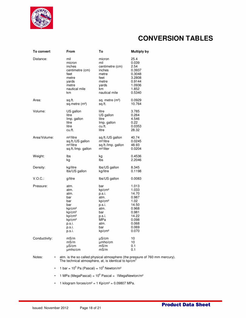
CONVERSION TABLES
To convert From To Multiply by Distance: mil micron 25.4 micron mil 0.039 inches centimetre (cm) 2.54 centimetre (cm) inches 0.3937 feet metre 0.3048 metre feet 3.2808 yards metre 0.9144 metre yards 1.0936 nautical mile km 1.852 km nautical mile 0.5340 Area: sq.ft. sq. metre (m²) 0.0929 sq.metre (m²) sq.ft. 10.764 Volume: US gallon litre 3.785 litre US gallon 0.264 Imp. gallon litre 4.546 litre Imp. gallon 0.22 litre cu.ft. 0.0353 cu.ft. litre 28.32 Area/Volume: m²/litre sq.ft./US gallon 40.74 sq.ft./US gallon m²/litre 0.0245 m²/litre sq.ft./Imp. gallon 48.93 sq.ft./Imp. gallon m²/liter 0.0204 Weight: lbs kg 0.4536 kg lbs 2.2046 Density: kg/litre lbs/US gallon 8.345 lbs/US gallon kg/litre 0.1198 V.O.C.: g/litre lbs/US gallon 0.0083 Pressure: atm. bar 1.013 atm. kp/cm² 1.033 atm. p.s.i. 14.70 bar atm. 0.987 bar kp/cm² 1.02 bar p.s.i. 14.50 kp/cm² atm. 0.968 kp/cm² bar 0.981 kp/cm² p.s.i. 14.22 kp/cm² MPa 0.098 p.s.i. atm. 0.068 p.s.i. bar 0.069 p.s.i. kp/cm² 0.070 Conductivity: mS/m µS/cm 10 mS/m µmho/cm 10 µS/cm mS/m 0.1 µmho/cm mS/m 0.1 Notes: • atm. is the so called physical atmosphere (the pressure of 760 mm mercury). The technical atmosphere, at, is identical to kp/cm
2
• 1 bar = 10
5 Pa (Pascal) = 10
5 Newton/m²
• 1 MPa (MegaPascal) = 10
6 Pascal = 1MegaNewton/m²
• 1 kilogram forces/cm² = 1 Kp/cm² = 0.09807 MPa.
Product Data Sheet
Issued: November 2012 Page 19 of 21
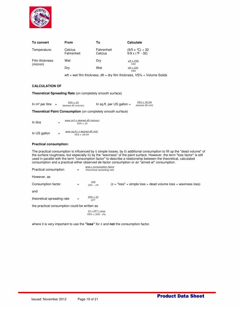
To convert From To Calculate Temperature: Celcius Fahrenheit (9/5 x °C) + 32 Fahrenheit Celcius 5/9 x (°F - 32) Film thickness: Wet Dry (micron) Dry Wet wft = wet film thickness, dft = dry film thickness, VS% = Volume Solids
CALCULATION OF Theoretical Spreading Rate (on completely smooth surface) In m² per litre = In sq.ft. per US gallon = Theoretical Paint Consumption (on completely smooth surface) In litre = In US gallon = Practical consumption: The practical consumption is influenced by i) simple losses, by ii) additional consumption to fill up the "dead volume" of the surface roughness, but especially iii) by the "waviness" of the paint surface. However, the term "loss factor" is still used in parallel with the term "consumption factor" to describe a relationship between the theoretical, calculated consumption and a practical either observed de-factor consumption or an "aimed at" consumption. Practical consumption = However, as Consumption factor = (z = "loss" = simple loss + dead volume loss + waviness loss) and theoretical spreading rate = the practical consumption could be written as where it is very important to use the "loss" for z and not the consumption factor.
wft x VS%
100
dft x 100
VS%
VS% x 10
desired dft (micron)
VS% x 16.04
desired dft (mil)
area (m²) x desired dft (micron)
VS% x 10
area (sq.ft.) x desired dft (mil)
VS% x 16.04
area x consumption factor
theoretical spreading rate
100
100 --- z%
VS% x 10
DFT
10 x DFT x area
VS% x (100 - z%)
Product Data Sheet
Issued: November 2012 Page 20 of 21
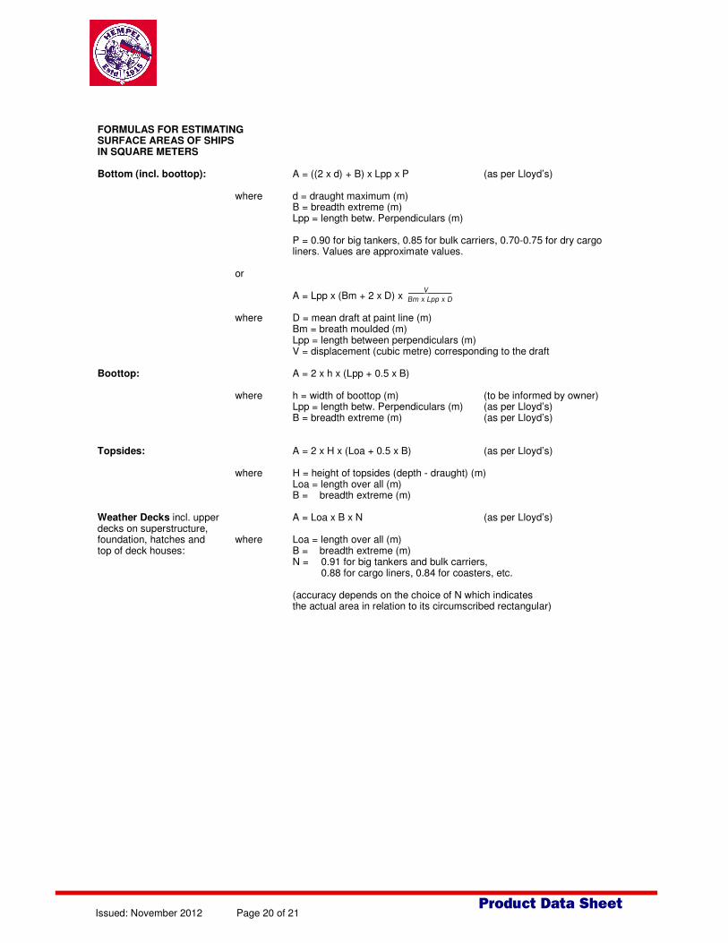
FORMULAS FOR ESTIMATING SURFACE AREAS OF SHIPS IN SQUARE METERS Bottom (incl. boottop): A = ((2 x d) + B) x Lpp x P (as per Lloyd’s) where d = draught maximum (m) B = breadth extreme (m) Lpp = length betw. Perpendiculars (m) P = 0.90 for big tankers, 0.85 for bulk carriers, 0.70-0.75 for dry cargo liners. Values are approximate values. or A = Lpp x (Bm + 2 x D) x where D = mean draft at paint line (m) Bm = breath moulded (m) Lpp = length between perpendiculars (m) V = displacement (cubic metre) corresponding to the draft Boottop: A = 2 x h x (Lpp + 0.5 x B) where h = width of boottop (m) (to be informed by owner) Lpp = length betw. Perpendiculars (m) (as per Lloyd’s) B = breadth extreme (m) (as per Lloyd’s) Topsides: A = 2 x H x (Loa + 0.5 x B) (as per Lloyd’s) where H = height of topsides (depth - draught) (m) Loa = length over all (m) B = breadth extreme (m) Weather Decks incl. upper A = Loa x B x N (as per Lloyd’s) decks on superstructure, foundation, hatches and where Loa = length over all (m) top of deck houses: B = breadth extreme (m) N = 0.91 for big tankers and bulk carriers, 0.88 for cargo liners, 0.84 for coasters, etc. (accuracy depends on the choice of N which indicates
the actual area in relation to its circumscribed rectangular)
____V______
Bm x Lpp x D
Product Data Sheet
Issued: November 2012 Page 21 of 21
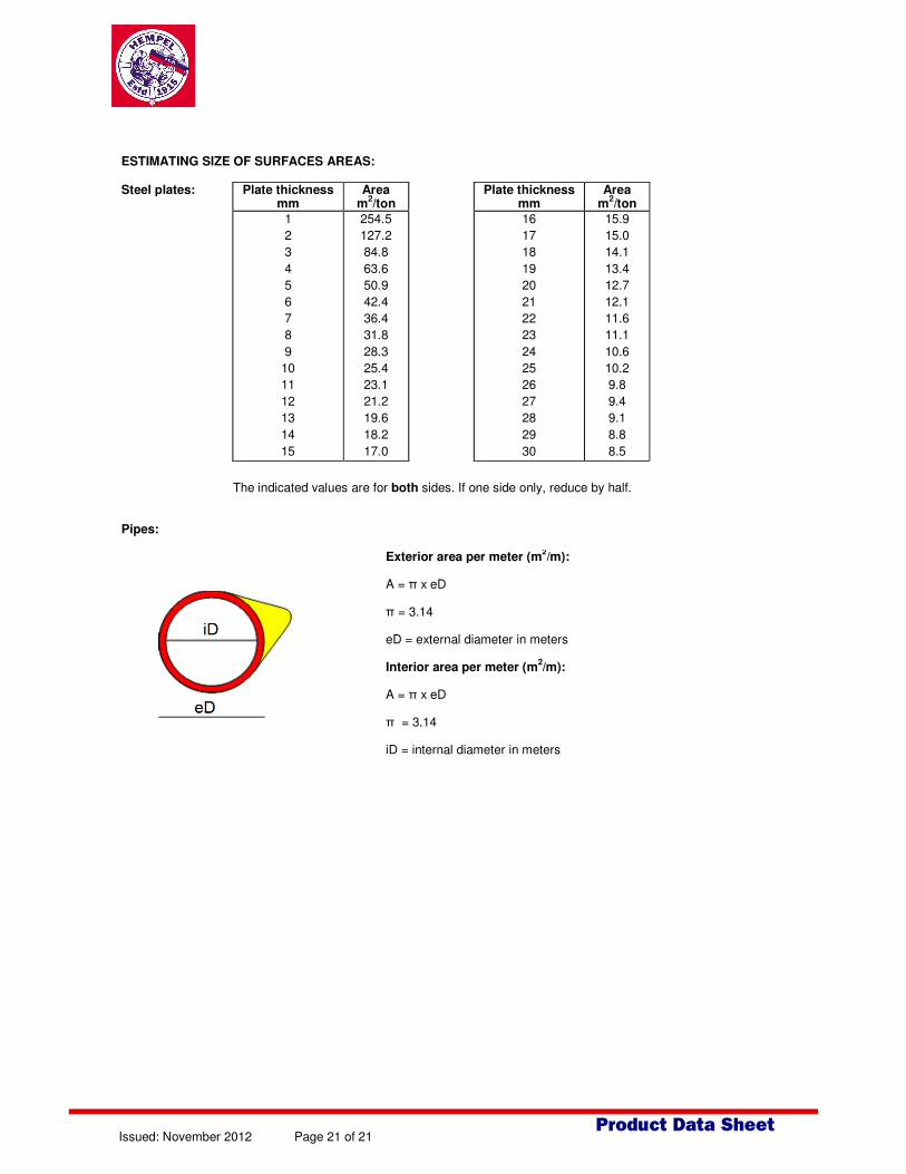
ESTIMATING SIZE OF SURFACES AREAS: Steel plates: Plate thickness
mm Area
m2/ton
Plate thickness mm
Area m
2/ton
1
2
3
4
5
6
7
8
9
10
11
12
13
14
15
254.5
127.2
84.8
63.6
50.9
42.4
36.4
31.8
28.3
25.4
23.1
21.2
19.6
18.2
17.0
16
17
18
19
20
21
22
23
24
25
26
27
28
29
30
15.9
15.0
14.1
13.4
12.7
12.1
11.6
11.1
10.6
10.2
9.8
9.4
9.1
8.8
8.5
The indicated values are for both sides. If one side only, reduce by half. Pipes:
Exterior area per meter (m2/m):
A = π x eD π = 3.14 eD = external diameter in meters Interior area per meter (m
2/m):
A = π x eD π = 3.14 iD = internal diameter in meters
Product Data Sheet
Issued: November 2012 Page 22 of 21
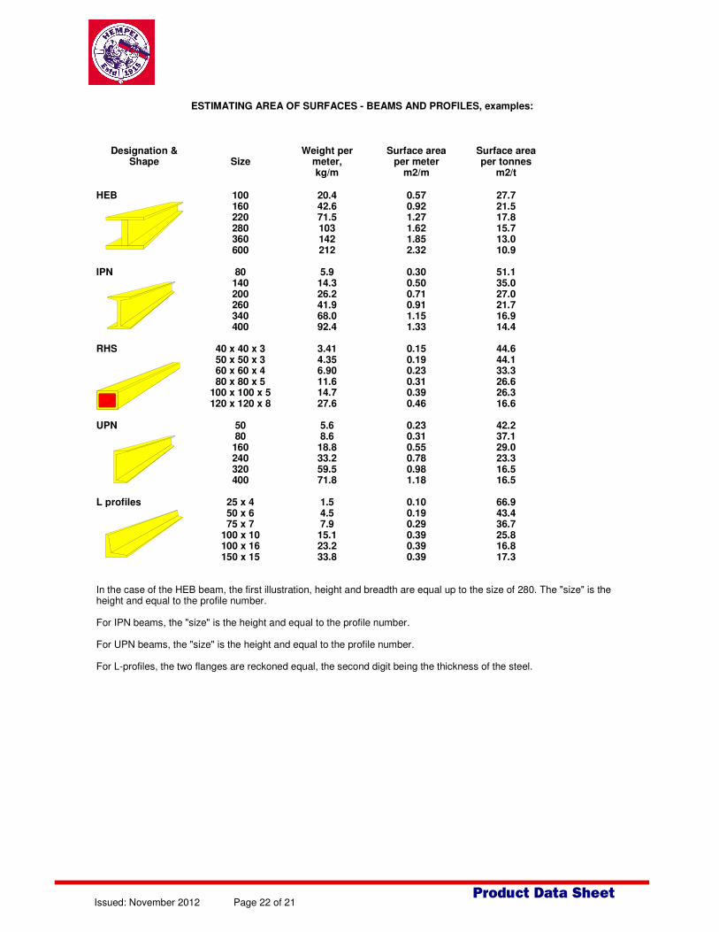
ESTIMATING AREA OF SURFACES - BEAMS AND PROFILES, examples:
Designation & Shape
Size
Weight per meter, kg/m
Surface area per meter
m2/m
Surface area per tonnes
m2/t
HEB
100 20.4 0.57 27.7 160 42.6 0.92 21.5 220 71.5 1.27 17.8 280 103 1.62 15.7 360 142 1.85 13.0 600 212 2.32 10.9
IPN
80 5.9 0.30 51.1 140 14.3 0.50 35.0 200 26.2 0.71 27.0 260 41.9 0.91 21.7 340 68.0 1.15 16.9 400 92.4 1.33 14.4
RHS
40 x 40 x 3 3.41 0.15 44.6 50 x 50 x 3 4.35 0.19 44.1 60 x 60 x 4 6.90 0.23 33.3 80 x 80 x 5 11.6 0.31 26.6
100 x 100 x 5 14.7 0.39 26.3 120 x 120 x 8 27.6 0.46 16.6
UPN
50 5.6 0.23 42.2 80 8.6 0.31 37.1
160 18.8 0.55 29.0 240 33.2 0.78 23.3 320 59.5 0.98 16.5 400 71.8 1.18 16.5
L profiles
25 x 4 1.5 0.10 66.9 50 x 6 4.5 0.19 43.4 75 x 7 7.9 0.29 36.7
100 x 10 15.1 0.39 25.8 100 x 16 23.2 0.39 16.8 150 x 15 33.8 0.39 17.3
In the case of the HEB beam, the first illustration, height and breadth are equal up to the size of 280. The "size" is the height and equal to the profile number. For IPN beams, the "size" is the height and equal to the profile number. For UPN beams, the "size" is the height and equal to the profile number. For L-profiles, the two flanges are reckoned equal, the second digit being the thickness of the steel.