give it a whirl - sulzer
TRANSCRIPT
In Motion
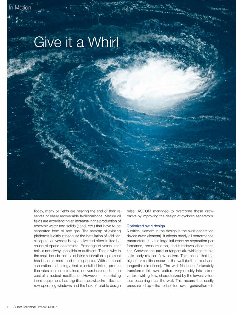
Give it a Whirl
12 Sulzer Technical Review 1/2015
Today, many oil fields are nearing the end of their re-serves of easily recoverable hydrocarbons. Mature oil fields are experiencing an increase in the production of reservoir water and solids (sand, etc.) that have to be separated from oil and gas. The revamp of existing platforms is difficult because the installation of addition-al separation vessels is expensive and often limited be-cause of space constraints. Exchange of vessel inter-nals is not always possible or sufficient. That is why in the past decade the use of inline separation equipment has become more and more popular. With compact separation technology that is installed inline, produc-tion rates can be maintained, or even increased, at the cost of a modest modification. However, most existing inline equipment has significant drawbacks—like nar-row operating windows and the lack of reliable design
rules. ASCOM managed to overcome these draw-backs by improving the design of cyclonic separators.
Optimized swirl designA critical element in the design is the swirl generation device (swirl element). It affects nearly all performance parameters. It has a large influence on separation per-formance, pressure drop, and turndown characteris-tics. Conventional (axial or tangential) swirls generate a solid-body rotation flow pattern. This means that the highest velocities occur at the wall (both in axial and tangential directions). The wall friction unfortunately transforms this swirl pattern very quickly into a free- vortex swirling flow, characterized by the lowest veloc-ities occurring near the wall. This means that costly pressure drop—the price for swirl generation—is
In Motion
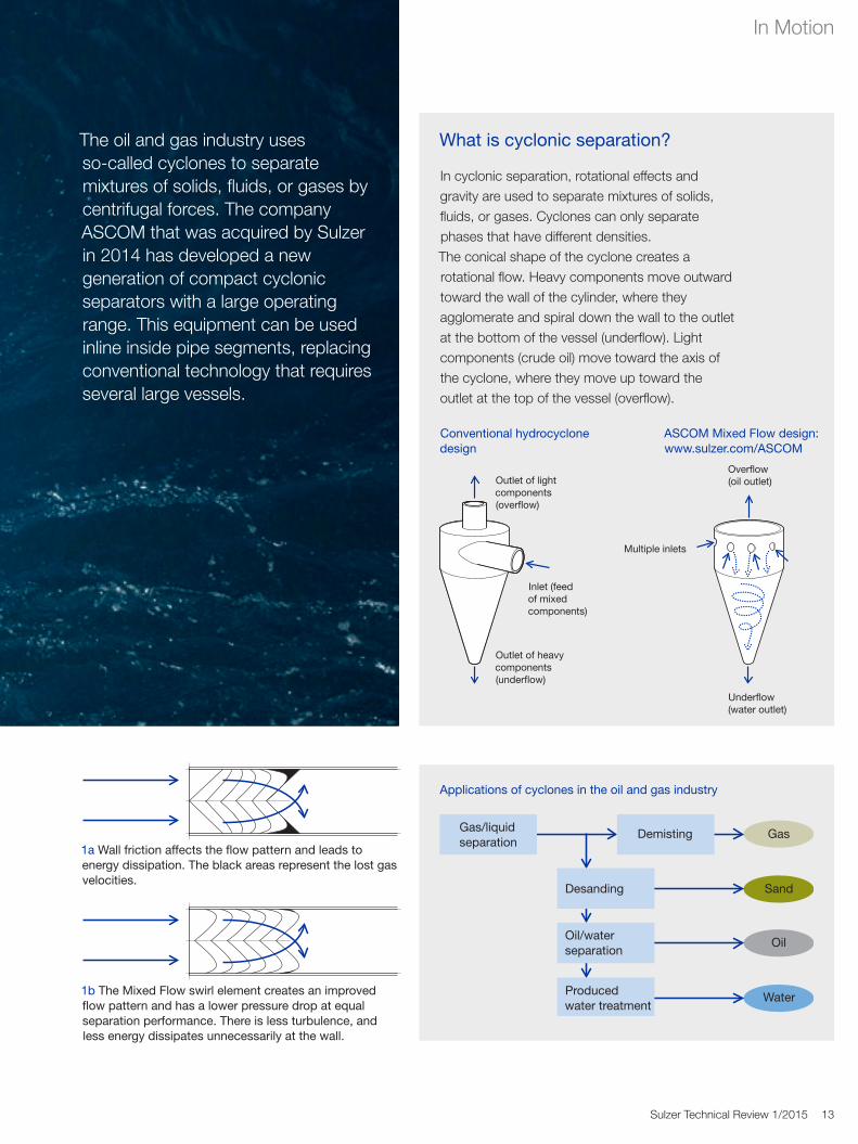
What is cyclonic separation?
In cyclonic separation, rotational effects and gravity are used to separate mixtures of solids, fluids, or gases. Cyclones can only separate phases that have different densities.The conical shape of the cyclone creates a rotational flow. Heavy components move outward toward the wall of the cylinder, where they agglomerate and spiral down the wall to the outlet at the bottom of the vessel (underflow). Light components (crude oil) move toward the axis of the cyclone, where they move up toward the outlet at the top of the vessel (overflow).
Sulzer Technical Review 1/2015 13
The oil and gas industry uses so-called cyclones to separate mixtures of solids, fluids, or gases by centrifugal forces. The company ASCOM that was acquired by Sulzer in 2014 has developed a new generation of compact cyclonic separators with a large operating range. This equipment can be used inline inside pipe segments, replacing conventional technology that requires several large vessels.
Gas/liquidseparation
Demisting
Desanding
Gas
Sand
Oil/waterseparation
Oil
Producedwater treatment
Water
Applications of cyclones in the oil and gas industry
Conventional hydrocyclone design
Overflow (oil outlet)
Underflow (water outlet)
Multiple inlets
Outlet of light components (overflow)
Inlet (feed of mixed components)
Outlet of heavy components (underflow)
1a Wall friction affects the flow pattern and leads to energy dissipation. The black areas represent the lost gas velocities.
1b The Mixed Flow swirl element creates an improved flow pattern and has a lower pressure drop at equal separation performance. There is less turbulence, and less energy dissipates unnecessarily at the wall.
ASCOM Mixed Flow design: www.sulzer.com/ASCOM
In Motion
14 Sulzer Technical Review 1/2015
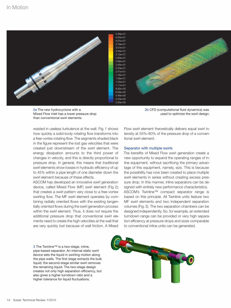
wasted in useless turbulence at the wall. Fig. 1 shows how quickly a solid-body rotating flow transforms into a free-vortex rotating flow. The segments shaded black in the figure represent the lost gas velocities that were created just downstream of the swirl element. The energy dissipation amounts to the third power of changes in velocity, and this is directly proportional to pressure drop. In general, this means that traditional swirl elements show losses in hydraulic efficiency of up to 45% within a pipe length of one diameter down the swirl element because of these effects.ASCOM has developed an innovative swirl generation device, called Mixed Flow (MF) swirl element (Fig. 2), that creates a swirl pattern very close to a free-vortex swirling flow. The MF swirl element operates by com-bining radially oriented flows with the existing tangen-tially oriented flows during the swirl generation process within the swirl element. Thus, it does not require the additional pressure drop that conventional swirl ele-ments need to create the high velocities at the wall that are very quickly lost because of wall friction. A Mixed
Flow swirl element theoretically delivers equal swirl in-tensity at 55%–60% of the pressure drop of a conven-tional swirl element.
Separator with multiple swirlsThe benefits of Mixed Flow swirl generation create a new opportunity to expand the operating ranges of in-line equipment, without sacrificing the primary advan-tage of this equipment, namely, size. This is because the possibility has now been created to place multiple swirl elements in series without creating excess pres-sure drop. In this manner, inline separators can be de-signed with entirely new performance characteristics.ASCOM’s Twinline™ compact separator range is based on this principle. All Twinline units feature two MF swirl elements and two independent separation volumes (Fig. 3). The two separation chambers can be designed independently. So, for example, an extended turndown range can be provided or very high separa-tion efficiency at pressure drops and sizes comparable to conventional inline units can be generated.
4.46e+014.24e+014.01e+013.79e+013.57e+013.34e+013.12e+012.90e+012.68e+012.45e+012.23e+012.01e+011.78e+011.56e+011.34e+011.11e+018.92e+006.69e+004.46e+002.23e+000.00e+00
2a The new hydrocyclone with a Mixed Flow inlet has a lower pressure drop than conventional swirl elements.
2b CFD (computational fluid dynamics) was used to optimize the swirl design.
3 The Twinline™ is a two-stage, inline, pipe-based separator. An internal static swirl device sets the liquid in swirling motion along the pipe walls. The first stage extracts the bulk liquid; the second-stage similar swirl removes the remaining liquid. The two-stage design creates not only high separation efficiency, but also gives a higher turndown ratio and a higher tolerance for liquid fluctuations.
Sulzer Technical Review 2/2014 15
In Motion
Sulzer Technical Review 1/2015 15
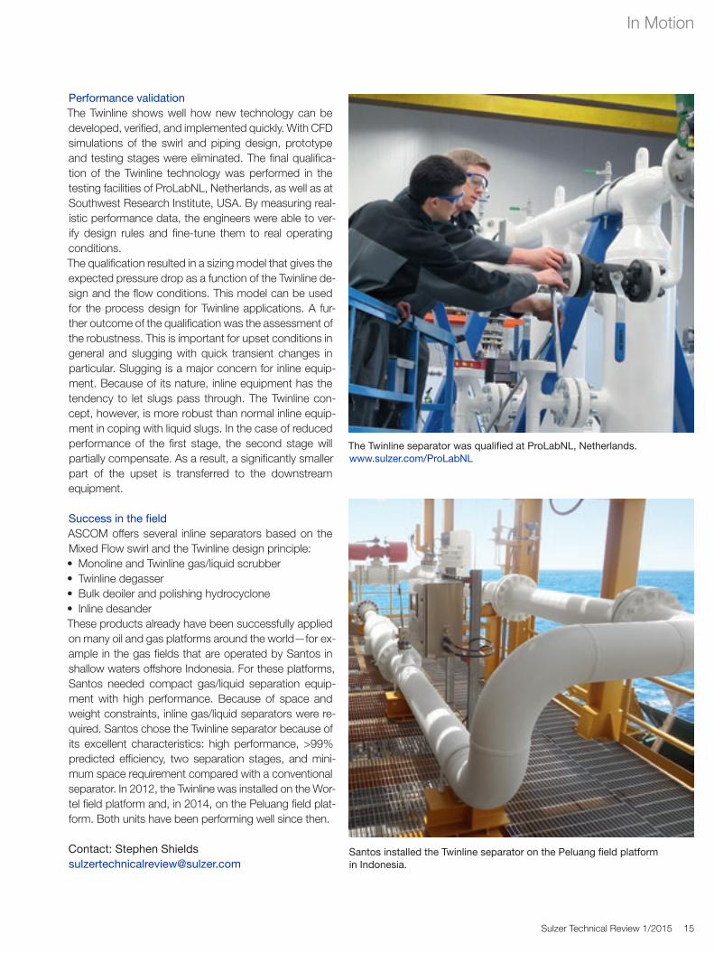
The Twinline separator was qualified at ProLabNL, Netherlands. www.sulzer.com/ProLabNL
Santos installed the Twinline separator on the Peluang field platform in Indonesia.
Performance validationThe Twinline shows well how new technology can be developed, verified, and implemented quickly. With CFD simulations of the swirl and piping design, prototype and testing stages were eliminated. The final qualifica-tion of the Twinline technology was performed in the testing facilities of ProLabNL, Netherlands, as well as at Southwest Research Institute, USA. By measuring real-istic performance data, the engineers were able to ver-ify design rules and fine-tune them to real operating conditions.The qualification resulted in a sizing model that gives the expected pressure drop as a function of the Twinline de-sign and the flow conditions. This model can be used for the process design for Twinline applications. A fur-ther outcome of the qualification was the assessment of the robustness. This is important for upset conditions in general and slugging with quick transient changes in particular. Slugging is a major concern for inline equip-ment. Because of its nature, inline equipment has the tendency to let slugs pass through. The Twinline con-cept, however, is more robust than normal inline equip-ment in coping with liquid slugs. In the case of reduced performance of the first stage, the second stage will partially compensate. As a result, a significantly smaller part of the upset is transferred to the downstream equipment.
Success in the fieldASCOM offers several inline separators based on the Mixed Flow swirl and the Twinline design principle:• Monoline and Twinline gas/liquid scrubber• Twinline degasser• Bulk deoiler and polishing hydrocyclone• Inline desanderThese products already have been successfully applied on many oil and gas platforms around the world—for ex-ample in the gas fields that are operated by Santos in shallow waters offshore Indonesia. For these platforms, Santos needed compact gas/liquid separation equip-ment with high performance. Because of space and weight constraints, inline gas/liquid separators were re-quired. Santos chose the Twinline separator because of its excellent characteristics: high performance, >99% predicted efficiency, two separation stages, and mini-mum space requirement compared with a conventional separator. In 2012, the Twinline was installed on the Wor-tel field platform and, in 2014, on the Peluang field plat-form. Both units have been performing well since then.
Contact: Stephen [email protected]