the model’s give this s9 a whirl - nar
TRANSCRIPT
IntroductionThe rocketeers that make up the U.S.
Spacemodeling team love to fly the FAI events. FAI is the sanctioning body for in-ternational rocket competitions and hosts its World Spacemodeling Championships (WSMC) in the summer of the even num-bered years. The NAR hosts the U.S. team selection flyoff as part of the Annual Rock-
etry Festival in the odd numbered years. Last July the 2019 flyoff was held in Mun-cie, Indiana. Since the FAI events seldom change we are given the challenge to con-tinually work to perfect a design over a
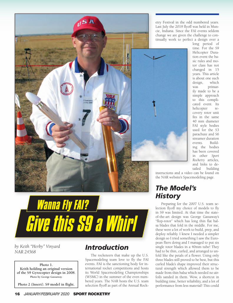
long period of time. For the S9 Helicopter Dura-tion event the ba-sic rules and mo-tor class has not changed in 15 years. This article is about one such design, which was primar-ily made to be a simple approach to this compli-cated event. Its helicopter re-covery rotor unit fits in the same 40 mm diameter FAI style bodies used for the S3 parachute and S6 streamer duration events. Build-ing the bodies has been covered in other Sport Rocketry articles, and links to de-tailed building
instructions and a video can be found on the NAR website’s Spacemodeling page.
The Model’s History
Preparing for the 2007 U.S. team se-lection flyoff my choice of models to fly in S9 was limited. At that time the state-of-the-art design was George Gassaway’s “flop-rotor” which has long thin flat bal-sa blades that fold in the middle. For me, these were a lot of work to build, prep, and deploy reliably. I knew I needed a simpler design so I tried something I saw the Euro-pean fliers doing and I managed to put six single rotor blades in a 40mm tube! They had to be thin, curled, and arranged to un-fold like the petals of a flower. Using only three blades still proved to be best, but this curled blade’s shape improved their struc-tural strength which allowed them to be made from thin balsa which needed no air-foils sanded in them. Wow, a shortcut in building time, better reliability, and a lot of performance from less material! This could
16 JANUARY/FEBRUARY 2020 SPORT ROCKETRY
Photo 1.Keith holding an original version
of the S9 Gyrocopter design in 2008. Photo by George Gassaway.
Photo 2 (Insert). S9 model in flight.
by Keith “Herby” Vinyard NAR 24568
Give this S9 a WhirlWanna Fly FAI? Wanna Fly FAI?

be a project worth pursuing, so fast for-ward 11 years to July 2018. At the WSMC held in Poland, the entire U.S. Junior and Senior teams flew models with rotors con-structed this way. Our best finish was from former NAR national contest board chair-man Steve Humphrey who placed 4th in the flyoff with nine other competitors, just missing being on the medal stand. And at the recent 2019 U.S. team selection flyoff, every S9 entry was made this way.
By the 2010 WSMC, the blade’s shape had become very close to what it still is today. The widest portion with the most pitch is near the hub and drives the rota-tion. The width gradually tapers to the tips, which are level with no pitch. In the early years the rotor unit was pushed out of the body with an ejection plug and the shock cord was mounted internal. The bodies were made with a steep 8-degree tapered tailcone which allowed for 11.25" long blades to fit in a minimum length body, by FAI rules.
At the 2011 U.S. team flyoff, the mod-el’s popularity was growing. About half of
the entries had curled blades. It was at that meet when Katherine Humphrey (Steve’s daughter) flew a model with a long nose cone shoulder that acted as a piston to pull the rotor unit out of the body when ejection gases pressurized the tube. This solved the problem of breaking the fragile blades at ejection, and quickly led to using the normal S3/S6 body having a 5 degree
tapered tailcone with a more aerodynamic shape. Now, longer 13.5" blades that ex-tend down to the motor tube fit in the min-imum length body. These changes made for higher boosts and longer descent times.
At the 2012 WSMC, half of the U.S. competitors flew models with these inno-vations, and another, mounting the shock cord externally. This system came about as a method of deploying the antennae of a Walston tracking transmitter from where it was coiled up in the body during boost.
Tim VanMilligan of Apogee Compo-nents published some very good articles in his Peak of Flight newsletter about mak-ing the curled blades, and on developing a hub with laser cut parts that are easier for young modelers to assemble. That hub is used in his Rotary Revolution FAI S9 com-petition kit. Tim and his daughters contin-ued to experiment with blade design for the basis of several NARAM Research and Development competition projects.
Numerous other R&D projects about the design have been made, and it was even scaled up and successfully flown by Alan Stokker in the G Helicopter Duration event at NARAM-59.
Undoubtedly, the design’s highest hon-or was taken at the 2014 WSMC in Bul-garia when Senior S9 team member Trip Barber took home an individual bronze medal. Doug Hillson has done a wonderful job drafting Trip’s model. Those plans can
SPORT ROCKETRY JANUARY/FEBRUARY 2020 17
Photo 3. Wet S9 blades taped to
mandrel (top) and wrapped with cloth strips (bottom).
Photo 4. Set of dry S9 formed blades
(with some more soaking in ammonia solution in background).

18 JANUARY/FEBRUARY 2020 SPORT ROCKETRY
Pin
Spruce Lever Arm1/16 in. 1/4 in. x 1.33 in.
Spruce Standoff1/16 in. 1/4 in. x 7/16 in.
Aluminum TubeNominal 3/32 in.Length 0.6 in.
Balsa Bulkhead 1/32 in. 22 mm corner to corner
Du-Bro #118 Small Nylon HingeModified by cutting to length and replacing pins with 0.025 in. music wire.
Hub Assembly Exploded ViewSCALE 4 : 5
Nose Cone Constructed using vacuum forming method.Commercially available at Apogee Components, PN # 20061.
Foam PlugEPS foam 1 7/8 in. lengthMust be a snug fit in body tube.
Gyrocopter shaft is glued inside nose assembly through foam plug and both bulkheads. Glue nose cone on last.
Nose Cone Assembly Exploded ViewSCALE 2 : 3
Plywood Bulkhead 1/64 in. 5/16 in. x 5/16 in.
Aluminum TubeLength 1/8 in.
Dihedral Angle 10°
A
View of Complete GyrocopterSCALE 2 : 5
Gyrocopter Shaft 0.06 in. nominal diameter carbon fiber, length is 12 in.Some fliers use 0.04 in. nominal diameter.Wrap shock cord around carbon fiber and glue with cyanoacrylate.Some fliers will extend length to past blade tip and install shock cord mount.
S9 Gyrocopter Plans2019 Sport Rocketry PlansDrawn by: Doug Hillson NAR #61624Dimensions: [in.] mm
Detail A SCALE 4 : 5
Install three 5/16 in. dental rubber bands during assembly.
Aluminum TubeLength 1/2 in. Secure with tape and do not glue to allow for hub removal.
Hub assembly should freely rotate on the gyrocopter shaft.The aluminum tube in the hub will spin between the 1/8 in. length tube and the 1/2 in. length tube.
Reinforce hub with nylon thread wrapped around hinges and spruce components.

SPORT ROCKETRY JANUARY/FEBRUARY 2020 19
Pin
Spruce Lever Arm1/16 in. 1/4 in. x 1.33 in.
Spruce Standoff1/16 in. 1/4 in. x 7/16 in.
Aluminum TubeNominal 3/32 in.Length 0.6 in.
Balsa Bulkhead 1/32 in. 22 mm corner to corner
Du-Bro #118 Small Nylon HingeModified by cutting to length and replacing pins with 0.025 in. music wire.
Hub Assembly Exploded ViewSCALE 4 : 5
Nose Cone Constructed using vacuum forming method.Commercially available at Apogee Components, PN # 20061.
Foam PlugEPS foam 1 7/8 in. lengthMust be a snug fit in body tube.
Gyrocopter shaft is glued inside nose assembly through foam plug and both bulkheads. Glue nose cone on last.
Nose Cone Assembly Exploded ViewSCALE 2 : 3
Plywood Bulkhead 1/64 in. 5/16 in. x 5/16 in.
Aluminum TubeLength 1/8 in.
Dihedral Angle 10°
A
View of Complete GyrocopterSCALE 2 : 5
Gyrocopter Shaft 0.06 in. nominal diameter carbon fiber, length is 12 in.Some fliers use 0.04 in. nominal diameter.Wrap shock cord around carbon fiber and glue with cyanoacrylate.Some fliers will extend length to past blade tip and install shock cord mount.
S9 Gyrocopter Plans2019 Sport Rocketry PlansDrawn by: Doug Hillson NAR #61624Dimensions: [in.] mm
Detail A SCALE 4 : 5
Install three 5/16 in. dental rubber bands during assembly.
Aluminum TubeLength 1/2 in. Secure with tape and do not glue to allow for hub removal.
Hub assembly should freely rotate on the gyrocopter shaft.The aluminum tube in the hub will spin between the 1/8 in. length tube and the 1/2 in. length tube.
Reinforce hub with nylon thread wrapped around hinges and spruce components.
be found at the NAR/FAI website.It has been a true pleasure watching
this un-named design evolve from its be-ginning. Without the interest from many of my NAR friends and U.S. teammates who like to experiment and think outside the box it would not have developed into what it is today. I eagerly wait seeing future in-novations and improvements!
Making the Blades
The trademark of this design is the cambered blade shape and high speed at which they spin. The blades are made from 1/32" C grain balsa with the straight trail-ing edge parallel with the grain. Soak them in a 20% ammonia to water solution until soft enough to form without cracking. Am-monia is used to solubilize plant lignin in many bio-chemical extracting processes, and has been used for many years to assist in shaping wood. My original blades were shaped on a 40mm FAI mandrel but now I use similar sized PVC and galvanized metal pipe since the blades are now longer than my original mandrel. I can also make more blades at one time. Another nice thing about using hollow pipe is that you can place a rope through its center and sus-pend it at a comfortable working height, which makes the wrapping process easier.
Mark the mandrel or pipe’s center-line in two or three places around it with a marker to have a guide for positioning the blades. Use masking tape to secure the ends of the wetted blades in place. I use strips of bedsheet about 3" wide to wrap the blades tightly to the mandrel. Tape one end of the cloth strip near one end of the mandrel and start the wrap on a 45° angle (see Photo 3). Secure the other end of the wrap with tape and allow sufficient time for the blades to completely dry before remov-ing. Marks in the outer surface of the balsa will be left from the wraps but will sand out with fine grit sandpaper. For sanding the upper side of the blades, support the blade on a piece of PVC pipe. Also, round all the edges. My blades are 13.5" long and 1.75" wide. At 2.125" from the root end they steadily taper to the tip where they are 3/4" wide. See the dry blades in Photo 4.
Making the HubThe “Herby Hub,” as Steve Humphrey
coined it, uses spruce or basswood lever

arms (blade arms) as extensions of the balsa blades, which also act as the dihe-dral stop when deployed. Commercially purchased #118 DU-BRO small nylon model airplane hinges are used to link the blade arms to the hub core. 0.625" dental rubber bands put around the hub’s alumi-num tube spindle are stretched out and at-tached around pins on the top of the blade arms to deploy the blades. A spacer be-tween the lever arm and the hinge creates the correct dihedral when the blades are deployed into position.
Sort the hinges so the knuckles are all arranged the same way. This way the blades (also all made in the same direc-tion) are interchangeable. Trim the hinge half that will be mounted in the hub core, cutting the corners off so the three hinges will fit together on a balsa hub plate and have space in the center of the plate for mounting the aluminum tube spindle. Use a drop of medium or thick CA to glue the hinges on the hub plate. Glue the top plate on with the grain running in a dif-ferent direction as the bottom plate. Care-fully add thin cyanoacrylate glue (CA) to the top and bottom surfaces of the hub plates as reinforcement, but don’t let the thin CA get into the moving part of the hinge or you will have some extra work to free them up!
Photo 5 shows the hub jig that makes alignment easy. This jig uses one half of the hinge to align the other (trimmed) half of the hinge onto a hub plate. The photo shows a black tube underneath for placing the aluminum tube into for its perpendic-ular alignment in the hub’s center. Photo 6 shows a hub being built on the jig. After the hub is complete, I use a Dremel cut-off wheel to grind off the flattened end of the hinge pins so they can be removed. Save them, these will be used as the pins in the blade arms that the rubber bands will be hooked on.
Consistency in building rotor units is a must. I strongly recommend using a jig for attaching the blade arms to the blades. The blade arm attachment jig in the full-page drawing is used in two steps. The first is to mark the cutout slot in the root end of the blades. The other end of the jig will align the blade arm in the cutout slot for gluing. This method attaches the blade arms close to the center of the blades’ root ends, and when the unit is folded and placed in the 40mm body it easily fits without touching the tube walls except at the blade tips in the tailcone.
20 JANUARY/FEBRUARY 2020 SPORT ROCKETRY
[13.5 in.]342.9 mm
Leading Edge
Trailing Edge
Cutout for blade attachmentAlternative blade attachmentdoes not utilize this cutout.
Centerline of 40 mm mandrel during blade constructionBlade is constructed by wetting balsa with ammonia, and placing on a 40 mm aluminum mandrel then wrapping tightly with an athletic bandage.
Blade PlanformScale 2:3
TipRoot
Blade Attachment ViewSCALE 1 : 1
24°
Blade Attachment Side View(Viewed tip to root)
SCALE 4 : 3
Example Blade Jig for CutoutSCALE 1 : 2
Cutout for attachment
Blade stop
Example Blade Jig for Hinge AlignmentSCALE 1 : 2
Alignment GuidesUsed to ensure proper blade alignment.
BladeSpruce Lever ArmSpruce Standoff
Blade is attached to spruce lever arm on high pressure side. Hub is parallel to the pitch angle of the tip.
Alternative Blade Attachment ViewSCALE 1 : 1
1/32 in. lightweight 4 to 6 lbs. balsa
Pitch angle at tip is 0 and at root is 24 .This pitch angle results from the geometry and construction of blade. The blade should be attached to the hub so that the hub is parallel to the pitch angle of the blade tip.
A jig is strongly recommended to achieve the correct attachment angle and placement on blade so the rotors most efficiently fit in body.
The alternative blade attachment method is likely easier to construct, but will likely result in poorer airflow near the blade root. A jig is still recommended for this method.
To use this attachment method, attach the blade at the blade tip's centerline.
Fluorescent bulb cover

SPORT ROCKETRY JANUARY/FEBRUARY 2020 21
[13.5 in.]342.9 mm
Leading Edge
Trailing Edge
Cutout for blade attachmentAlternative blade attachmentdoes not utilize this cutout.
Centerline of 40 mm mandrel during blade constructionBlade is constructed by wetting balsa with ammonia, and placing on a 40 mm aluminum mandrel then wrapping tightly with an athletic bandage.
Blade PlanformScale 2:3
TipRoot
Blade Attachment ViewSCALE 1 : 1
24°
Blade Attachment Side View
(Viewed tip to root)SCALE 4 : 3
Example Blade Jig for CutoutSCALE 1 : 2
Cutout for attachment
Blade stop
Example Blade Jig for Hinge AlignmentSCALE 1 : 2
Alignment GuidesUsed to ensure proper blade alignment.
BladeSpruce Lever ArmSpruce Standoff
Blade is attached to spruce lever arm on high pressure side. Hub is parallel to the pitch angle of the tip.
Alternative Blade Attachment ViewSCALE 1 : 1
1/32 in. lightweight 4 to 6 lbs. balsa
Pitch angle at tip is 0 and at root is 24 .This pitch angle results from the geometry and construction of blade. The blade should be attached to the hub so that the hub is parallel to the pitch angle of the blade tip.
A jig is strongly recommended to achieve the correct attachment angle and placement on blade so the rotors most efficiently fit in body.
The alternative blade attachment method is likely easier to construct, but will likely result in poorer airflow near the blade root. A jig is still recommended for this method.
To use this attachment method, attach the blade at the blade tip's centerline.
Fluorescent bulb cover

22 JANUARY/FEBRUARY 2020 SPORT ROCKETRY
You can use the alternative blade at-tachment method as shown in the draw-ing where the blade arms are attached on the bottom of the blades and are centered in line with the center of the 3/4" wide blade tips. However, this method moves the blade arm attachment location toward the blade’s trailing edge, and will require more room when the folded unit is placed in the body. Note that aligning the blade arm with the centerline of the 3/4" width of the blade’s tip gives the tip zero pitch. If the arm is positioned closer to the trail-ing edge, the blade will have more negative incidence overall and will spin up fast, but lose lifting efficiency at the outer region of the rotor. If the arm is positioned further from the trailing edge, positive incidence at the tips will create more lift in the outer region, but will have a harder time initiat-ing rotation after ejection, and if extreme, will stall the tips and not rotate.
With either blade arm attachment method, attach the hinge halves by wrap-ping thread through the holes in the hinges and around the blade arms. The distance between the holes in the hinges is conve-niently very close to the width of the blade arms, which properly aligns the hinge on
the blade arm. Before attaching, make sure the hinge knuckles are oriented correctly to join the hinge halves on the hub. Use thin CA to reinforce the hinge/blade arm joint and thread.
Drill a small hole on a 15 degree angle through the top side of the blade arms and put the original hinge pins in the holes, leaving enough pin exposed to hook the rubber band on. Cut off any excess on the bottom side and use thin CA to secure in place. Join the hinges back together using .025 music wires as the replacements for the original pins, and bend the wire ends 90 degrees to secure them in place. Hook up the rubber bands and adjust the dihe-dral by sanding/filing off the ends of the blade arms where they meet the upper hub plate. If too much is removed, thick CA can be used to build it back up.
Making the Central Shaft Assembly
The backbone of the rotor unit is a 12" long x .06" (1.5mm) diameter carbon rod. Photo 5.
Jig used to build the S9 hub.
Photo 6. A hub being built on the jig.

One end is glued into a 1.875" long foam ejection plug that acts as the nose cone shoulder and ejection piston.
The ejection plugs are cut out of sheet foam using a plug “cutting” tool. You will need to make this tool by wrapping heavy, epoxy saturated fiberglass cloth around your 40 mm mandrel, similar to the way you make an FAI body. An article on mak-ing plugs may be found on the NAR web-site’s Spacemodeling page.
EPS (expanded polystyrene) foam works perfect for making plugs. It is white, somewhat spongy, bead foam that weighs a mere 1/2 gram. Center the carbon rod through the plug, extending about 1/4" and through a small plywood plate. Wrap
SPORT ROCKETRY JANUARY/FEBRUARY 2020 23
rubber bands will be wrapped around it and not be placed around the shim. Be-low the hub’s aluminum spindle tube add another 1/2" long piece of aluminum tube and tape it to the carbon rod to hold the free-wheeling hub assembly in position. At the bottom end of the carbon rod attach a piece of 75 lb. braided Kevlar line about 43" long as the shock cord. Photos 7 and 8 show the completed rotor core.
Tuning the Rotor Unit
Once you have assembled the rotor unit and it is on the central shaft assembly with the rubber bands hooked up, you will need to tune the balance, pitch, and dihe-dral. Dihedral, or the angle that the de-ployed blades are at in relation to the cen-tral shaft, is the least critical of the three.
No Yolking!Our Eggstravagnza Egglofting Kits are back!
www.asp-rocketry.comAerospace Speciality Products
Scale, Educational And Competition Model
Rocket Kits, Components and Supplies
Photo 7. Completed rotor core.
Photo 8. Underside of completed rotor core
with blades deployed.
this protruding end of the rod with thread and glue to secure the plate on the end of the rod. Glue the nose cone on the top of the plug with foam safe glue. Below the foam plug, friction fit another small ply-wood plate onto the rod, and push it up against the underneath side of the plug. Slide a 1/8" long piece of 3/32" OD alu-minum tube over the carbon rod and up against the plywood plate, then slide the rotor unit on. The 1/8" tube will shim the deployed blades of the rotor unit away from the foam plug when deployed, and act as a bushing for the free-wheeling hub to ride against. Note that the upper portion of the aluminum spindle tube of the hub needs to be long enough so that all three

I’m not sure if there is an optimal dihedral angle for sink rate, but the more angle the unit has, the quicker it will transition and start rotation, especially if the unit is heavi-er than the rocket body. Try to make the three blade angles the same, but if they are a degree or two off, it doesn’t seem to cause major problems, unlike balance and pitch differences.
While holding the central shaft side-ways, make sure the blades are balanced. Gravity will orient heavier blades down to indicate which blades need to be light-ened. You can sand the upper surface of the blades to make fine adjustments, but you may also have to add weight to the lighter ones. This is also a good time to treat the end grain of the blade tips with CA or ep-oxy to prevent damage from the ejection charge, since this process may unevenly add weight. When the blades are balanced the hub will not rotate on its own, no mat-
24 JANUARY/FEBRUARY 2020 SPORT ROCKETRY
Photo 10. Secure Kevlar line around
engine and tape motor and line in place.
Photo 9. Kevlar shock line needs to
be straight with no twisting.
Rocket Motors, Kits, & Accessories Rocket Motors, Kits, & Accessories Delivered to Your DoorstepDelivered to Your DoorstepRocket Motors, Kits, & Accessories Rocket Motors, Kits, & Accessories Delivered to Your DoorstepDelivered to Your Doorstep
✔ Same/Next Day Shipping
✔ Real Time Inventory
✔ Order Confirmation
✔ Order Tracking
✔ No Memberships
✔ Shipping to Alaska please inquire
We carry Aerotech motors & kits, LOC Precision kits, Jolly Logic electronics, and adhesives!

26 JANUARY/FEBRUARY 2020 SPORT ROCKETRY
ter which blade is positioned up. Out of balance blades will make the unit descend with a revolving motion, instead of staying positioned on its vertical central axis.
The same symptom will occur if the blades have differing pitch. If you built consistently, using jigs, they should have the same pitch, however changing humid-ity will affect balsa wood and will often need minor adjustments. Holding the cen-tral shaft upright, rotate the unit to inspect the pitch of the blades at the tips. If they are slightly off, twist them by hand to give them a temporary set.
Flying the Model Fold the rotor blades together, pull
the Kevlar line taught around the tip of one blade and up the side as you insert the unit straight into the rocket body. The line needs to be straight up the inside of the tube, out the top of the body and straight down to the end of the tube with no twist-ing (see Photo 9).
Insert a motor, secure the Kevlar line around the motor where it meets the tube and tape the motor, line, and tube together (see Photo 10). Use a motor with an appro-priate ejection delay time so the ejection
is close to or short of apogee. Fortunately Estes A3-4T motors work very well, since they are the only lightweight NAR safety certified motors allowed for current con-test use in the United States.
At ejection the rotor unit is forced out, the blades deploy, and when the line is fully extended, the body will be pulled around backward. This swinging action of the body absorbs the excess energy of ejec-tion and prevents damaging any part of the model. The Kevlar cord easily handles the heat of the ejection charge from dozens of flights and it is more likely that you will lose the model before you need to change a scorched and weakened cord. As a mat-ter of fact I have lost four models out of my last six contest flights, so my present challenge with this decade old design is to develop a lightweight and reliable de-ther-malizer system. Which just goes to show that flying these FAI events year after year never gets boring, only more challenging. So if this sounds interesting to you, start building, flying and experimenting. And good luck in future U.S. team flyoffs!
Keith loads his S9 model on into a tower at the 2019 U.S. team tryouts.
www.siriusrocketry.com
motors - chutes - tools -
adhesives - parts -
great kits from the
finest manufacturers -
and so much more in
our secure online store!
It’s now time to have
some serious fun with
rocketry, visit us today!
The Sirius Rocketry
Eradicator is the
newest kit in our
Transition Series of
kits, rockets that fly
comfortably on F
& G motors and
are built to fly on an
H when you’re ready
for your level one!
From model to High
Power, we’re serious
about rocketry!
Transitionintofun!

References:Hillson, Doug. (2018, August 26). FAI A Gyrocopter 2018 (S9A),
Retrieved October 16, 2018, from https://www.nar.org/ wp-content/uploads/2018/08/FAI-S9A-Gyrocopter-2018.pdf
O’Bryan, David. Lightweight Fiberglass Tubes. Retrieved October 16, 2018, from http://www.nar.org/contest-flying/fai-spacemodeling/construction-techniques/lightweight- fiberglass-tubes/
S9 – Gyrocopter Duration. Retrieved October 16, 2018, from https://www.nar.org/contest-flying/fai-spacemodeling/ fai-events-for-wsmc/s9-gyrocopter-duration/
Tomasche, Andrew. Foam Ejection Plugs. Retrieved November 19, 2018, from https://www.nar.org/contest-flying/fai- spacemodeling/construction-techniques/foam- ejection-plugs/
Van Milligan, Tim. (2013, June 2). Peak of Flight #342
“Fabrication of Shaped and Curved Helicopter Rotor Blades.” Retrieved October 16, 2018, from https://www.apogeerockets.com/education/downloads/Newsletter342.pdf
Van Milligan, Tim. (2014, October 7). Peak of Flight #375 “Development of a New and Simplified Helicopter Rotor Hub.” Retrieved October 16, 2018, from https:// www.apogeerockets.com/education/downloads/ Newsletter375.pdf
SPORT ROCKETRY JANUARY/FEBRUARY 2020 27