user manual - mold-masters
TRANSCRIPT

User Manualversion 1
Original Instructions

Contents
Section 1 - Introduction ...................................................1-11.1 Intended Use ......................................................................................................1-11.2 Documentation ...................................................................................................1-11.3 Release Details ..................................................................................................1-11.4 Warranty .............................................................................................................1-11.5 Returned Goods Policy .......................................................................................1-21.6 Movement or Resale of Mold-Masters Products or Systems .............................1-21.7 Copyright ............................................................................................................1-21.8 Units of Measure and Conversion Factors .........................................................1-3
Section 2 - Global Support ..............................................2-12.1 Corporate Offices................................................................................................2-12.2 International Representatives .............................................................................2-2
Section 3 - Safety..............................................................3-13.1 Safety Hazards ...................................................................................................3-23.2 Operational Hazards ...........................................................................................3-53.3 General Safety Symbols .....................................................................................3-73.4 Wiring Check ......................................................................................................3-83.5 Lockout Safety ....................................................................................................3-9
3.5.1 Electrical Lockout .....................................................................................3-103.5.2 Energy Forms and Lockout Guidelines....................................................3-11
3.6 Disposal ............................................................................................................3-123.7 Hot Runner Safety Hazards ..............................................................................3-13
Section 4 - Preparation ....................................................4-14.1 Tools Required ....................................................................................................4-14.2 Screw Lengths ....................................................................................................4-24.3 Unpacking ...........................................................................................................4-34.4 Cleaning .............................................................................................................4-34.5 Establish Your System Type ...............................................................................4-4
4.5.1 System with a ThinPAK-Series Nozzle ......................................................4-4
Section 5 - Assembly .......................................................5-15.1 Cutaway of a ThinPAK System ...........................................................................5-15.2 Water-Cooled Gate Insert Installation (Optional) ................................................5-25.3 Thermocouple Installation ..................................................................................5-35.4 Thermocouple Removal For Back Mounted (Standard) Thermocouples ...........5-55.5 Nozzle Insertion ..................................................................................................5-6
5.5.1 Step Installation .........................................................................................5-65.5.2 Nozzle Insertion—ThinPAK-Series Systems .............................................5-7
5.6 Nozzle Wire Layout ............................................................................................5-95.6.1 Back Mounted Thermocouples ..................................................................5-95.6.2 Front Mounted Thermocouples ..................................................................5-9
i
ThinPAK User Manual © 2021 Mold-Masters (2007) Limited. All Rights Reserved.
5.7 Valve Bushings .................................................................................................5-105.7.1 Types of Valve Bushings ..........................................................................5-105.7.2 Valve Bushing Installation ........................................................................5-105.7.3 Valve Bushing Installation—ThinPAK Series ...........................................5-125.7.4 Valve Bushing Installation with Screws—ThinPAK Series .......................5-14
5.8 Mount the Manifold ...........................................................................................5-155.8.1 Manifold Locator ......................................................................................5-165.8.2 Manifold-Locating Dowel Pin ...................................................................5-175.8.3 Manifold and Slot Locator ........................................................................5-17
5.9 Manifold Thermocouple Installation ..................................................................5-185.10 Main Manifolds ...............................................................................................5-19
5.10.1 Inlet Seal Installation - Without Step .....................................................5-195.10.2 Inlet Seal Installation - With Step ...........................................................5-20
5.11 Support Bushing Installation ...........................................................................5-215.12 Valve Disk Installation .....................................................................................5-22
5.12.1 Clamp Plate Assembly (B-Screws) ........................................................5-235.13 Inlet Components Installation .........................................................................5-24
5.13.1 Back Plate Installation ...........................................................................5-245.13.2 Center Heater Installation ......................................................................5-255.13.3 Three Piece Center Heater Installation ..................................................5-255.13.4 Inlet Extension Installation .....................................................................5-265.13.5 Inlet Extension with Pressure Sleeve ....................................................5-27
Section 6 - Electrical Testing ...........................................6-16.1 Safety .................................................................................................................6-16.2 Electrical Wiring Check .......................................................................................6-16.3 Electrical Safety Testing .....................................................................................6-2
6.3.1 Verify Equipment to its Technical Documentation ......................................6-26.3.2 Insulation Resistance Test ........................................................................6-26.3.3 Verification of Conditions for Protection by Automatic Disconnection of Supply
6-36.3.4 Verification of Continuity of Protective Bonding Circuit ..............................6-36.3.5 Verification of Fault Loop Impedance ........................................................6-36.3.6 Thermocouple Continuity Test ...................................................................6-46.3.7 Pinch Point Test .........................................................................................6-46.3.8 Heating Element Check .............................................................................6-46.3.9 Ungrounded Thermocouple Continuity Test ..............................................6-5
6.4 Thermocouple Wiring Guidelines .......................................................................6-56.5 Functional Test with a Temperature Controller ...................................................6-56.6 Re-testing ...........................................................................................................6-5
Section 7 - Hot Half Assembly .........................................7-17.1 Hot Half Assembly ..............................................................................................7-17.2 Stack Mold Cavity Plate Installation ...................................................................7-3
Section 8 - System Startup and Shutdown ....................8-18.1 Pre-Startup .........................................................................................................8-18.2 Startup ................................................................................................................8-2
8.2.1 Standard Hot Runner Systems ..................................................................8-2
ii
© 2021 Mold-Masters (2007) Limited. All Rights Reserved.
ThinPAK User Manual
8.2.2 Stack Mold Systems ..................................................................................8-38.3 Shutdown ............................................................................................................8-3
8.3.1 Standard Hot Runner Systems ..................................................................8-38.3.2 Stack Mold System ....................................................................................8-4
Section 9 - Color Change .................................................9-19.1 General Tips .......................................................................................................9-19.2 Procedure A: Simple and Effective .....................................................................9-19.3 Procedure B: More Comprehensive ...................................................................9-2
Section 10 - Hydraulic / Pneumatic Actuators ............ 10-110.1 Valve Actuator Installation and Assembly .......................................................10-110.2 Pre-Installation ................................................................................................10-210.3 Cylinder Bottom Assembly ..............................................................................10-210.4 Piston Assembly .............................................................................................10-3
10.4.1 6X00 Series and 7100 Series ................................................................10-310.5 Cylinder Top Assembly ...................................................................................10-410.6 Valve Pin Finishing of Tip ...............................................................................10-4
10.6.1 6X00 Series ...........................................................................................10-410.6.2 7100 Series ............................................................................................10-510.6.3 8X00 Series ...........................................................................................10-7
10.7 Valve Pin Lapping Procedure for Tapered Valve Pins ....................................10-810.7.1 6X00 Series ...........................................................................................10-8
10.8 Valve Pin Assembly ........................................................................................10-910.8.1 6X00 Series ...........................................................................................10-910.8.2 Hydraulic Limit Switch Option (6500 Series and 6600 Series) ............10-1010.8.3 7100 Series ..........................................................................................10-11
10.9 Install the Valve Actuator to the Hydraulic Plate ...........................................10-1210.9.1 6X00 Series .........................................................................................10-1210.9.2 Hydraulic Limit Switch Option (6500 Series and 6600 Series) ............10-14
10.10 Proximity Sensor Installation for Hydraulic Limit Switch Option .................10-1510.10.1 Cutout Options Based on Stroke .......................................................10-16
10.11 Test the Proximity Sensor for Hydraulic Limit Switch Option ......................10-1710.12 Maintenance Procedures for 5500 Series, 6X00 Series and 7100 Series .10-17
10.12.1 For Oil Systems: ................................................................................10-1810.12.2 For Pneumatic Systems: ....................................................................10-18
10.13 Extraction Tools for Hydraulic and Pneumatic Actuators ............................10-19
Section 11 - Maintenance ...............................................11-111.1 Valve Disk Removal ........................................................................................11-1
11.1.1 Extraction of 1-piece Valve Disk ............................................................11-211.1.2 Extraction of 2-piece Valve Disk ............................................................11-4
11.2 Valve Disk Extraction Tool Overview ...............................................................11-611.3 Terminal End Removal and Installation ...........................................................11-8
11.3.1 Terminal End Removal ...........................................................................11-811.3.2 Terminal Installation ...............................................................................11-811.3.3 Terminal Assembly .................................................................................11-9
11.4 Gate Seal Maintenance ................................................................................11-1211.4.1 Multi-Cavity Systems ...........................................................................11-1211.4.2 Gate Seal Removal ..............................................................................11-13
iii
ThinPAK User Manual © 2021 Mold-Masters (2007) Limited. All Rights Reserved.
11.4.3 Gate Seal Replacement .......................................................................11-1411.5 Clean Nozzle Insulator Cap ..........................................................................11-1611.6 Installing Nozzle Insulator Cap .....................................................................11-1611.7 Valve Actuator Maintenance .........................................................................11-1711.8 Check Nozzle Tip Height ..............................................................................11-1711.9 Latches .........................................................................................................11-1811.10 Latch the Cavity Plate to the Core Half (Cold Half) ....................................11-1811.11 Latch the Cavity Plate to the Manifold Plate (Hot Half) ...............................11-2011.12 Torque Settings ...........................................................................................11-22
11.12.1 Gate Seal Torque Settings .................................................................11-2211.12.2 System and Plate Screw Torques ......................................................11-23
Section 12 - Troubleshooting ....................................... 12-1
Section 13 - Glossary .................................................... 13-1
Index ......................................................................................I
iv
© 2021 Mold-Masters (2007) Limited. All Rights Reserved.
ThinPAK User Manual

Section 1 - IntroductionThe purpose of this manual is to assist users in the integration, operation and maintenance of a Hot Runner. This manual is designed to cover most system configurations. If you need additional information specific to your system, or information in another language, please contact your representative or a Mold-Masters office.
1.1 Intended UseMold-Masters Hot Runner systems have been built to process thermoplastic material at the required temperature for injection molding and must not be used for any other purpose.This manual is written for use by skilled persons who are familiar with injection molding machinery and their terminology. Operators should be familiar with plastic injection molding machines and the controls of such equipment. Maintenance persons should have sufficient understanding of electrical safety to appreciate the dangers of 3-phase supplies. They should know how to take appropriate measures to avoid any danger from electrical supplies.
1.2 DocumentationThis manual is part of the documentation package for your order and should be referenced along with the following documents included in the package:• The Bill of Materials (BOM). Together with the General Assembly drawing, the Bill of
Materials should be referenced when ordering spare parts.• General Assembly drawing used to integrate your Hot Runner system into the mold.• Hot Half drawing used to integrate Hot Half into cavity plate.• CE declaration of conformity and declaration of incorporation (EU only)
NOTEThis manual should also be used in conjunction with other relevant manuals, e.g. Mold Machine Manual and Controller Manual.
1.3 Release DetailsWhen ordering this manual, please reference the document number below.
Table 1-1 Release Details
Document Number Release Date Version
TP--UM--EN--00--01 March 2021 01
1.4 WarrantyFor current warranty information please refer to the documents available from our website www.moldmasters.com/support/warranty or contact your Mold-Masters representative.
1-1INTRODUCTION
ThinPAK User Manual © 2021 Mold-Masters (2007) Limited. All Rights Reserved.

1.5 Returned Goods PolicyPlease do not return any parts to Mold-Masters without pre-authorization and a return authorization number supplied by Mold-Masters.Our policy is one of continuous improvement and we reserve the right to alter product specifications at any time without giving notice.
1.6 Movement or Resale of Mold-Masters Products or SystemsThis documentation is intended for use in the country of destination for which the product or system was purchased.Mold-Masters takes no responsibility for documentation of products or systems if they are relocated or resold outside the intended country of destination, as stated on the accompanying invoice and/or waybill.
1.7 Copyright© 2021 Mold-Masters (2007) Limited. All Rights Reserved. Mold-Masters® and the Mold-Masters logo are trademarks of Mold-Masters.
1-2
© 2021 Mold-Masters (2007) Limited. All Rights Reserved.
INTRODUCTION
ThinPAK User Manual
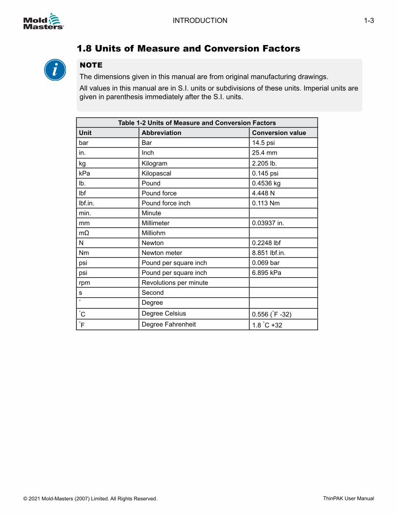
1.8 Units of Measure and Conversion Factors
NOTEThe dimensions given in this manual are from original manufacturing drawings.All values in this manual are in S.I. units or subdivisions of these units. Imperial units are given in parenthesis immediately after the S.I. units.
Table 1-2 Units of Measure and Conversion FactorsUnit Abbreviation Conversion valuebar Bar 14.5 psiin. Inch 25.4 mmkg Kilogram 2.205 lb.kPa Kilopascal 0.145 psilb. Pound 0.4536 kglbf Pound force 4.448 Nlbf.in. Pound force inch 0.113 Nmmin. Minutemm Millimeter 0.03937 in.mΩ MilliohmN Newton 0.2248 lbfNm Newton meter 8.851 lbf.in.psi Pound per square inch 0.069 barpsi Pound per square inch 6.895 kParpm Revolutions per minutes Second° Degree°C Degree Celsius 0.556 (°F -32)°F Degree Fahrenheit 1.8 °C +32
1-3INTRODUCTION
ThinPAK User Manual © 2021 Mold-Masters (2007) Limited. All Rights Reserved.

Section 2 - Global Support2.1 Corporate Offices
ASIAN HEADQUARTERS CHINA/HONG KONG/TAIWAN Mold-Masters (KunShan) Co, Ltd Zhao Tian Rd Lu Jia Town, KunShan City Jiang Su Province People’s Republic of China tel: +86 512 86162882 fax: +86 512-86162883 [email protected]
JAPAN Mold-Masters K.K. 1-4-17 Kurikidai, AsaokuKawasaki, KanagawaJapan, 215-0032tel: +81 44 986 2101fax: +81 44 986 [email protected]
GLOBAL HEADQUARTERS CANADA Mold-Masters (2007) Limited 233 Armstrong Avenue Georgetown, Ontario Canada L7G 4X5 tel: +1 905 877 0185 fax: +1 905 877 6979 [email protected]
SOUTH AMERICAN HEADQUARTERS BRAZIL Mold-Masters do Brasil Ltda. R. James Clerk Maxwel,280 – Techno Park, CampinasSão Paulo, Brazil, 13069-380tel: +55 19 3518 [email protected]
UNITED KINGDOM & IRELAND Mold-Masters (UK) Ltd Netherwood Road Rotherwas Ind. Est. Hereford, HR2 6JU United Kingdom tel: +44 1432 265768 fax: +44 1432 263782 [email protected]
EUROPEAN HEADQUARTERS GERMANY / SWITZERLAND Mold-Masters Europa GmbH Neumattring 1 76532 Baden-Baden, Germany tel: +49 7221 50990fax: +49 7221 53093 [email protected]
INDIAN HEADQUARTERS INDIA Milacron India PVT Ltd. (Mold-Masters Div.) 3B,Gandhiji Salai, Nallampalayam, Rathinapuri Post, Coimbatore T.N. 641027 tel: +91 422 423 4888 fax: +91 422 423 4800 [email protected]
USA Mold-Masters Injectioneering LLC, 29111 Stephenson Highway, Madison Heights, MI 48071, USA tel: +1 800 450 2270 (USA only) tel: +1 (248) 544-5710 fax: +1 (248) 544-5712 [email protected] Regional Offices
AUSTRIA / East and South East Europe Mold-Masters Handelsges.m.b.H. Pyhrnstrasse 16 A-4553 SchlierbachAustriatel: +43 7582 51877fax: +43 7582 51877 [email protected]
ITALY Mold-Masters Italia Via Germania, 23 35010 Vigonza (PD) Italy tel: +39 049/5019955 fax: +39 049/5019951 [email protected]
CZECH REPUBLIC Mold-Masters Europa GmbH Hlavni 823 75654 Zubri Czech Republic tel: +420 571 619 017 fax: +420 571 619 018 [email protected]
KOREA Mold-Masters Korea Ltd. E dong, 2nd floor, 2625-6, Jeongwang-dong, Siheung City, Gyeonggi-do, 15117, South Koreatel: +82-31-431-4756 [email protected]
FRANCE Mold-Masters France ZI la Marinière, 2 Rue Bernard Palissy 91070 Bondoufle, France tel: +33 (0) 1 78 05 40 20 fax: +33 (0) 1 78 05 40 30 [email protected]
MEXICO Milacron Mexico Plastics Services S.A. de C.V.Circuito El Marques norte #55Parque Industrial El MarquesEl Marques, Queretaro C.P. 76246 Mexicotel: +52 442 713 5661 (sales)tel: +52 442 713 5664 (service) [email protected]
2-1GLOBAL SUPPORT
ThinPAK User Manual © 2021 Mold-Masters (2007) Limited. All Rights Reserved.

2.2 International Representatives
Corporate Offices - continuedMold-Masters Regional Offices (cont.) SPAIN Mold-Masters Europa GmbHC/ Tecnología, 17 Edificio Canadá PL. 0 Office A2 08840 – ViladecansBarcelonatel: +34 93 575 41 29e: [email protected]
TURKEY Mold-Masters Europa GmbH Merkezi Almanya Türkiye İstanbul Şubesi Alanaldı Caddesi Bahçelerarası Sokak No: 31/1 34736 İçerenköy-Ataşehir Istanbul, Turkey tel: +90 216 577 32 44 fax: +90 216 577 32 45 [email protected]
SINGAPORE* Mold-Masters Singapore PTE. Ltd. No 48 Toh Guan Road East #06-140 Enterprise Hub Singapore 608586 Republic of Singapore tel: +65 6261 7793 fax: +65 6261 8378 [email protected]*Coverage includes SoutheastAsia, Australia, and New Zealand
Mold-Masters International Representatives
Argentina Sollwert S.R.L. La Pampa 2849 2∫ B C1428EAY Buenos Aires Argentina tel: +54 11 4786 5978 fax: +54 11 4786 5978 Ext. 35 [email protected]
Denmark* Englmayer A/S Dam Holme 14-16 DK – 3660 Stenloese Denmark tel: +45 46 733847 fax: +45 46 733859 [email protected]*Coverage includes Norwayand Sweden
Israel ASAF Industries Ltd. 29 Habanai Street PO Box 5598 Holon 58154 Israel tel: +972 3 5581290 fax: +972 3 5581293 [email protected]
RussiaSystem LLC Prkt Marshala Zhukova 4 123308 Moscow Russiatel: +7 (495) 199-14-51 [email protected]
BelarusHP Promcomplect Sharangovicha 13 220018 Minsktel: +375 29 683-48-99 fax: +375 17 397-05-65 e:[email protected]
Finland**Oy Scalar Ltd. Tehtaankatu 10 11120 Riihimaki Finland tel: +358 10 387 2955 fax: +358 10 387 2950 [email protected] **Coverage includes Estonia
Portugal Gecim LDA Rua Fonte Dos Ingleses, No 2 Engenho 2430-130 Marinha Grande Portugal tel: +351 244 575600 fax: +351 244 575601 [email protected]
Slovenia RD PICTA tehnologije d.o.o. Žolgarjeva ulica 2 2310 Slovenska Bistrica Slovenija +386 59 969 [email protected]
Bulgaria Mold-Trade OOD 62, AleksandrovskaSt. Ruse City Bulgaria tel: +359 82 821 054 fax: +359 82 821 054 [email protected]
Greece Ionian Chemicals S.A. 21 Pentelis Ave. 15235 Vrilissia, Athens Greece tel: +30 210 6836918-9 fax: +30 210 6828881 [email protected]
Romania Tehnic Mold Trade SRL Str. W. A Mozart nr. 17 Sect. 2 020251 Bucharesti Romaniatel: +4 021 230 60 51 fax : +4 021 231 05 86 [email protected]
UkraineCompany Park LLC Gaydamatska str., 3, office 116 Kemenskoe City Dnipropetrovsk Region 51935, Ukrainetel: +38 (038) 277-82-82 [email protected]
2-2
© 2021 Mold-Masters (2007) Limited. All Rights Reserved.
GLOBAL SUPPORT
ThinPAK User Manual
Section 3 - SafetyPlease be aware that the safety information provided by Mold-Masters does not absolve the integrator and employer from understanding and following international and local standards for safety of machinery. It is the responsibility of the end integrator to integrate the final system, provide necessary e-stop connections, safety interlocks and guarding, to select the appropriate electrical cable for the region of use and to ensure compliance with all relevant standards.It is the responsibility of the employer to:• Properly train and instruct its personnel in the safe operation of equipment, including
the use of all the safety devices.• Provide its personnel with all necessary protective clothing, including a face shield and
heat resistant gloves.• Ensure the original and continuing competence of personnel caring for, setting up,
inspecting and maintaining injection molding equipment.• Establish and follow a program of periodic and regular inspections of injection molding
equipment to ensure it is in safe operating condition and proper adjustment.• Ensure that no modifications, repairs, or rebuild of portions are made to the equipment
that reduces the level of safety existing at time of manufacture or remanufacture.
3-1SAFETY
ThinPAK User Manual © 2021 Mold-Masters (2007) Limited. All Rights Reserved.
3.1 Safety HazardsWARNINGRefer to all machine manuals and local regulations and codes for safety information.
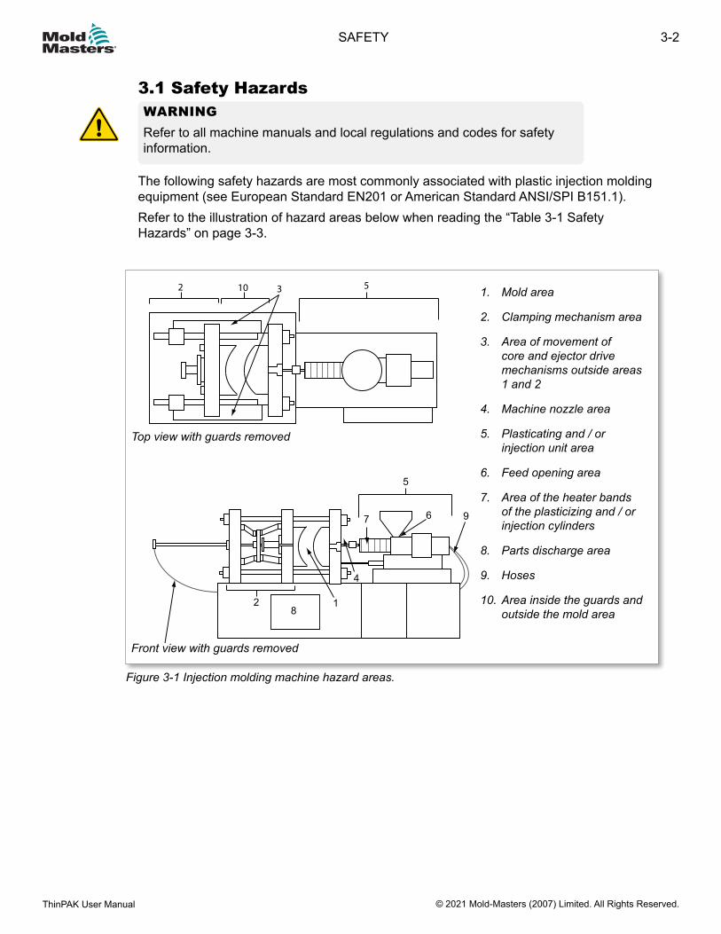
The following safety hazards are most commonly associated with plastic injection molding equipment (see European Standard EN201 or American Standard ANSI/SPI B151.1).Refer to the illustration of hazard areas below when reading the “Table 3-1 Safety Hazards” on page 3-3.
Figure 3-1 Injection molding machine hazard areas.
Top view with guards removed
Front view with guards removed
2 10 53
Top View with Guards Removed
2
5
9
1
4
7 6 9
8
Front View with Guards Removed
1. Mold area
2. Clamping mechanism area
3. Area of movement of core and ejector drive mechanisms outside areas 1 and 2
4. Machine nozzle area
5. Plasticating and / or injection unit area
6. Feed opening area
7. Area of the heater bands of the plasticizing and / or injection cylinders
8. Parts discharge area
9. Hoses
10. Area inside the guards and outside the mold area
3-2
© 2021 Mold-Masters (2007) Limited. All Rights Reserved.
SAFETY
ThinPAK User Manual
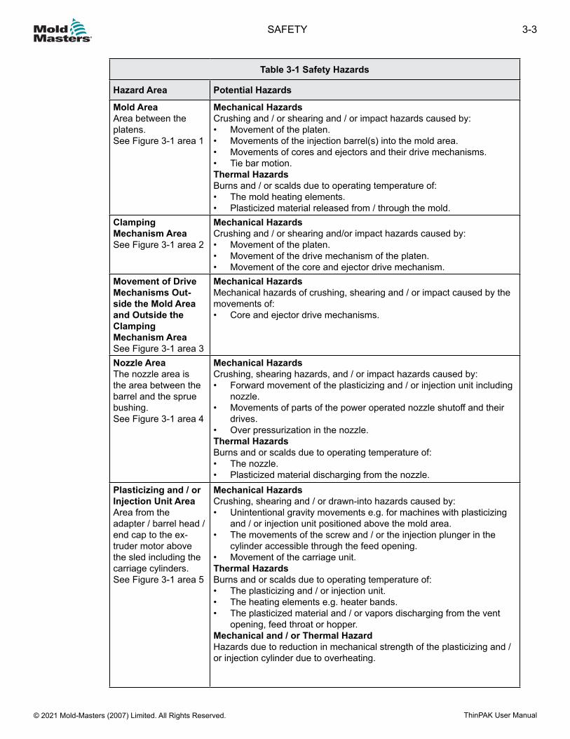
Table 3-1 Safety Hazards
Hazard Area Potential Hazards
Mold AreaArea between the platens.See Figure 3-1 area 1
Mechanical HazardsCrushing and / or shearing and / or impact hazards caused by:• Movement of the platen.• Movements of the injection barrel(s) into the mold area.• Movements of cores and ejectors and their drive mechanisms.• Tie bar motion.Thermal HazardsBurns and / or scalds due to operating temperature of:• The mold heating elements.• Plasticized material released from / through the mold.
ClampingMechanism AreaSee Figure 3-1 area 2
Mechanical HazardsCrushing and / or shearing and/or impact hazards caused by:• Movement of the platen.• Movement of the drive mechanism of the platen.• Movement of the core and ejector drive mechanism.
Movement of Drive Mechanisms Out-side the Mold Area and Outside the Clamping Mechanism AreaSee Figure 3-1 area 3
Mechanical HazardsMechanical hazards of crushing, shearing and / or impact caused by the movements of:• Core and ejector drive mechanisms.
Nozzle AreaThe nozzle area is the area between the barrel and the sprue bushing.See Figure 3-1 area 4
Mechanical HazardsCrushing, shearing hazards, and / or impact hazards caused by:• Forward movement of the plasticizing and / or injection unit including
nozzle.• Movements of parts of the power operated nozzle shutoff and their
drives.• Over pressurization in the nozzle.Thermal HazardsBurns and or scalds due to operating temperature of:• The nozzle.• Plasticized material discharging from the nozzle.
Plasticizing and / or Injection Unit AreaArea from the adapter / barrel head / end cap to the ex-truder motor above the sled including the carriage cylinders.See Figure 3-1 area 5
Mechanical HazardsCrushing, shearing and / or drawn-into hazards caused by:• Unintentional gravity movements e.g. for machines with plasticizing
and / or injection unit positioned above the mold area.• The movements of the screw and / or the injection plunger in the
cylinder accessible through the feed opening.• Movement of the carriage unit.Thermal HazardsBurns and or scalds due to operating temperature of:• The plasticizing and / or injection unit.• The heating elements e.g. heater bands.• The plasticized material and / or vapors discharging from the vent
opening, feed throat or hopper.Mechanical and / or Thermal HazardHazards due to reduction in mechanical strength of the plasticizing and /or injection cylinder due to overheating.
3-3SAFETY
ThinPAK User Manual © 2021 Mold-Masters (2007) Limited. All Rights Reserved.
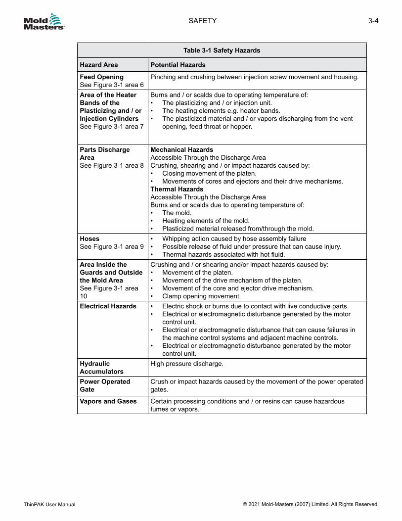
Table 3-1 Safety Hazards
Hazard Area Potential Hazards
Feed OpeningSee Figure 3-1 area 6
Pinching and crushing between injection screw movement and housing.
Area of the Heater Bands of the Plasticizing and / or Injection CylindersSee Figure 3-1 area 7
Burns and / or scalds due to operating temperature of:• The plasticizing and / or injection unit.• The heating elements e.g. heater bands.• The plasticized material and / or vapors discharging from the vent
opening, feed throat or hopper.
Parts Discharge AreaSee Figure 3-1 area 8
Mechanical HazardsAccessible Through the Discharge AreaCrushing, shearing and / or impact hazards caused by:• Closing movement of the platen.• Movements of cores and ejectors and their drive mechanisms.Thermal HazardsAccessible Through the Discharge AreaBurns and or scalds due to operating temperature of:• The mold.• Heating elements of the mold.• Plasticized material released from/through the mold.
HosesSee Figure 3-1 area 9
• Whipping action caused by hose assembly failure• Possible release of fluid under pressure that can cause injury.• Thermal hazards associated with hot fluid.
Area Inside the Guards and Outside the Mold AreaSee Figure 3-1 area 10
Crushing and / or shearing and/or impact hazards caused by:• Movement of the platen.• Movement of the drive mechanism of the platen.• Movement of the core and ejector drive mechanism.• Clamp opening movement.
Electrical Hazards • Electric shock or burns due to contact with live conductive parts.• Electrical or electromagnetic disturbance generated by the motor
control unit.• Electrical or electromagnetic disturbance that can cause failures in
the machine control systems and adjacent machine controls.• Electrical or electromagnetic disturbance generated by the motor
control unit.Hydraulic Accumulators
High pressure discharge.
Power Operated Gate
Crush or impact hazards caused by the movement of the power operated gates.
Vapors and Gases Certain processing conditions and / or resins can cause hazardous fumes or vapors.
3-4
© 2021 Mold-Masters (2007) Limited. All Rights Reserved.
SAFETY
ThinPAK User Manual
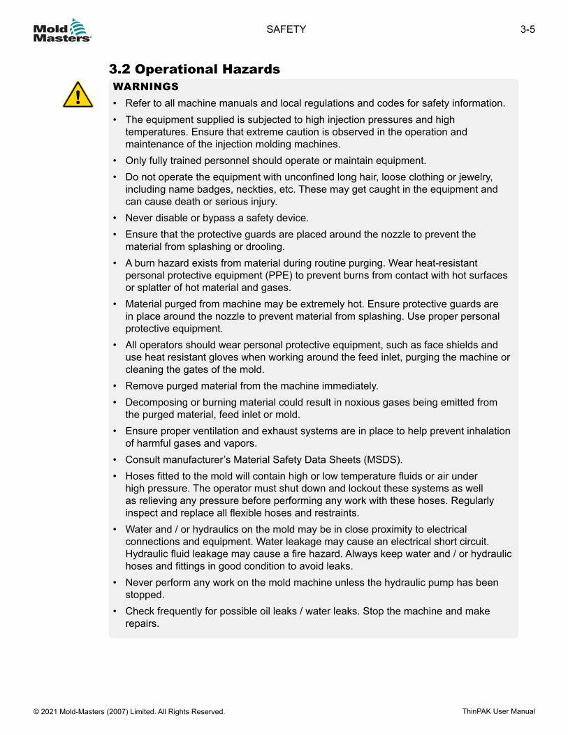
3.2 Operational HazardsWARNINGS• Refer to all machine manuals and local regulations and codes for safety information.• The equipment supplied is subjected to high injection pressures and high
temperatures. Ensure that extreme caution is observed in the operation and maintenance of the injection molding machines.
• Only fully trained personnel should operate or maintain equipment.• Do not operate the equipment with unconfined long hair, loose clothing or jewelry,
including name badges, neckties, etc. These may get caught in the equipment and can cause death or serious injury.
• Never disable or bypass a safety device.• Ensure that the protective guards are placed around the nozzle to prevent the
material from splashing or drooling.• A burn hazard exists from material during routine purging. Wear heat-resistant
personal protective equipment (PPE) to prevent burns from contact with hot surfaces or splatter of hot material and gases.
• Material purged from machine may be extremely hot. Ensure protective guards are in place around the nozzle to prevent material from splashing. Use proper personal protective equipment.
• All operators should wear personal protective equipment, such as face shields and use heat resistant gloves when working around the feed inlet, purging the machine or cleaning the gates of the mold.
• Remove purged material from the machine immediately.• Decomposing or burning material could result in noxious gases being emitted from
the purged material, feed inlet or mold.• Ensure proper ventilation and exhaust systems are in place to help prevent inhalation
of harmful gases and vapors.• Consult manufacturer’s Material Safety Data Sheets (MSDS).• Hoses fitted to the mold will contain high or low temperature fluids or air under
high pressure. The operator must shut down and lockout these systems as well as relieving any pressure before performing any work with these hoses. Regularly inspect and replace all flexible hoses and restraints.
• Water and / or hydraulics on the mold may be in close proximity to electrical connections and equipment. Water leakage may cause an electrical short circuit. Hydraulic fluid leakage may cause a fire hazard. Always keep water and / or hydraulic hoses and fittings in good condition to avoid leaks.
• Never perform any work on the mold machine unless the hydraulic pump has been stopped.
• Check frequently for possible oil leaks / water leaks. Stop the machine and make repairs.
3-5SAFETY
ThinPAK User Manual © 2021 Mold-Masters (2007) Limited. All Rights Reserved.
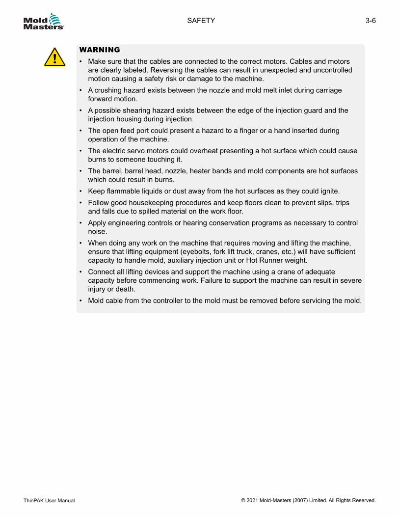
WARNING• Make sure that the cables are connected to the correct motors. Cables and motors
are clearly labeled. Reversing the cables can result in unexpected and uncontrolled motion causing a safety risk or damage to the machine.
• A crushing hazard exists between the nozzle and mold melt inlet during carriage forward motion.
• A possible shearing hazard exists between the edge of the injection guard and the injection housing during injection.
• The open feed port could present a hazard to a finger or a hand inserted during operation of the machine.
• The electric servo motors could overheat presenting a hot surface which could cause burns to someone touching it.
• The barrel, barrel head, nozzle, heater bands and mold components are hot surfaces which could result in burns.
• Keep flammable liquids or dust away from the hot surfaces as they could ignite.• Follow good housekeeping procedures and keep floors clean to prevent slips, trips
and falls due to spilled material on the work floor.• Apply engineering controls or hearing conservation programs as necessary to control
noise.• When doing any work on the machine that requires moving and lifting the machine,
ensure that lifting equipment (eyebolts, fork lift truck, cranes, etc.) will have sufficient capacity to handle mold, auxiliary injection unit or Hot Runner weight.
• Connect all lifting devices and support the machine using a crane of adequate capacity before commencing work. Failure to support the machine can result in severe injury or death.
• Mold cable from the controller to the mold must be removed before servicing the mold.
3-6
© 2021 Mold-Masters (2007) Limited. All Rights Reserved.
SAFETY
ThinPAK User Manual
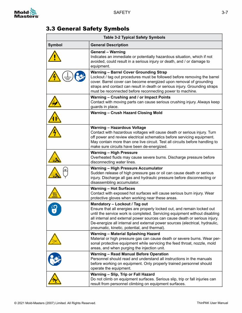
3.3 General Safety SymbolsTable 3-2 Typical Safety Symbols
Symbol General DescriptionGeneral – WarningIndicates an immediate or potentially hazardous situation, which if not avoided, could result in a serious injury or death, and / or damage to equipment.
Warning – Barrel Cover Grounding StrapLockout / tag out procedures must be followed before removing the barrel cover. Barrel cover can become energized upon removal of grounding straps and contact can result in death or serious injury. Grounding straps must be reconnected before reconnecting power to machine.Warning – Crushing and / or Impact PointsContact with moving parts can cause serious crushing injury. Always keep guards in place.Warning – Crush Hazard Closing Mold
Warning – Hazardous VoltageContact with hazardous voltages will cause death or serious injury. Turn off power and review electrical schematics before servicing equipment. May contain more than one live circuit. Test all circuits before handling to make sure circuits have been de-energized.Warning – High PressureOverheated fluids may cause severe burns. Discharge pressure before disconnecting water lines.
Warning – High Pressure AccumulatorSudden release of high pressure gas or oil can cause death or serious injury. Discharge all gas and hydraulic pressure before disconnecting or disassembling accumulator.Warning – Hot SurfacesContact with exposed hot surfaces will cause serious burn injury. Wear protective gloves when working near these areas.Mandatory – Lockout / Tag outEnsure that all energies are properly locked out, and remain locked out until the service work is completed. Servicing equipment without disabling all internal and external power sources can cause death or serious injury. De-energize all internal and external power sources (electrical, hydraulic, pneumatic, kinetic, potential, and thermal).Warning – Material Splashing HazardMaterial or high pressure gas can cause death or severe burns. Wear per-sonal protective equipment while servicing the feed throat, nozzle, mold areas, and when purging the injection unit.Warning – Read Manual Before OperationPersonnel should read and understand all instructions in the manuals before working on equipment. Only properly trained personnel should operate the equipment.Warning – Slip, Trip or Fall HazardDo not climb on equipment surfaces. Serious slip, trip or fall injuries can result from personnel climbing on equipment surfaces.
3-7SAFETY
ThinPAK User Manual © 2021 Mold-Masters (2007) Limited. All Rights Reserved.
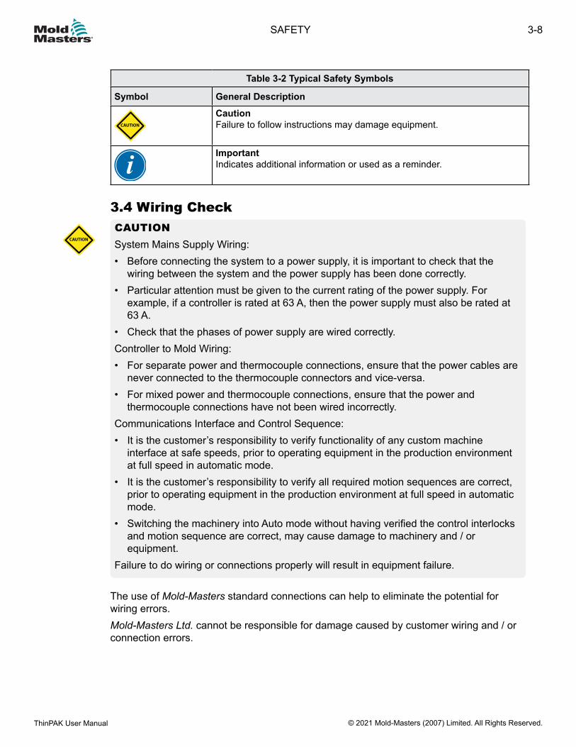
Table 3-2 Typical Safety Symbols
Symbol General Description
CAUTION
CautionFailure to follow instructions may damage equipment.
ImportantIndicates additional information or used as a reminder.
3.4 Wiring CheckCAUTIONSystem Mains Supply Wiring:• Before connecting the system to a power supply, it is important to check that the
wiring between the system and the power supply has been done correctly.• Particular attention must be given to the current rating of the power supply. For
example, if a controller is rated at 63 A, then the power supply must also be rated at 63 A.
• Check that the phases of power supply are wired correctly.Controller to Mold Wiring:• For separate power and thermocouple connections, ensure that the power cables are
never connected to the thermocouple connectors and vice-versa.• For mixed power and thermocouple connections, ensure that the power and
thermocouple connections have not been wired incorrectly.Communications Interface and Control Sequence:• It is the customer’s responsibility to verify functionality of any custom machine
interface at safe speeds, prior to operating equipment in the production environment at full speed in automatic mode.
• It is the customer’s responsibility to verify all required motion sequences are correct, prior to operating equipment in the production environment at full speed in automatic mode.
• Switching the machinery into Auto mode without having verified the control interlocks and motion sequence are correct, may cause damage to machinery and / or equipment.
Failure to do wiring or connections properly will result in equipment failure.
CAUTION
The use of Mold-Masters standard connections can help to eliminate the potential for wiring errors.Mold-Masters Ltd. cannot be responsible for damage caused by customer wiring and / or connection errors.
3-8
© 2021 Mold-Masters (2007) Limited. All Rights Reserved.
SAFETY
ThinPAK User Manual

3.5 Lockout SafetyWARNING
DO NOT enter the cabinet without first ISOLATING the supplies.
High voltage and amperage cables are connected to the controller and the mold. Electrical power must be shut off and lockout / tag out procedures followed prior to installing or removing any cables.Use lockout / tag out to prevent operation during maintenance.All maintenance should be performed by properly trained personnel based on local laws and regulation. Electrical products may not be grounded when removed from the assembled or normal operating condition.Ensure proper grounding of all electrical components before performing any maintenance to avoid potential risk of electrical shock.Often power sources are inadvertently turned on or valves are opened mistakenly before maintenance work is completed, resulting in serious injuries and fatalities. Therefore, it is important to ensure that all energies are properly locked out and that they remain locked out until the work is completed.If a lockout is not performed, uncontrolled energies could cause:
• Electrocution from contact with live circuits• Cuts, bruises, crushing, amputations or death, resulting from entanglement with
belts, chains, conveyors, rollers, shafts, impellers• Burns from contact with hot parts, materials or equipment such as furnaces• Fires and explosions• Chemical exposures from gases or liquids released from pipelines
3-9SAFETY
ThinPAK User Manual © 2021 Mold-Masters (2007) Limited. All Rights Reserved.
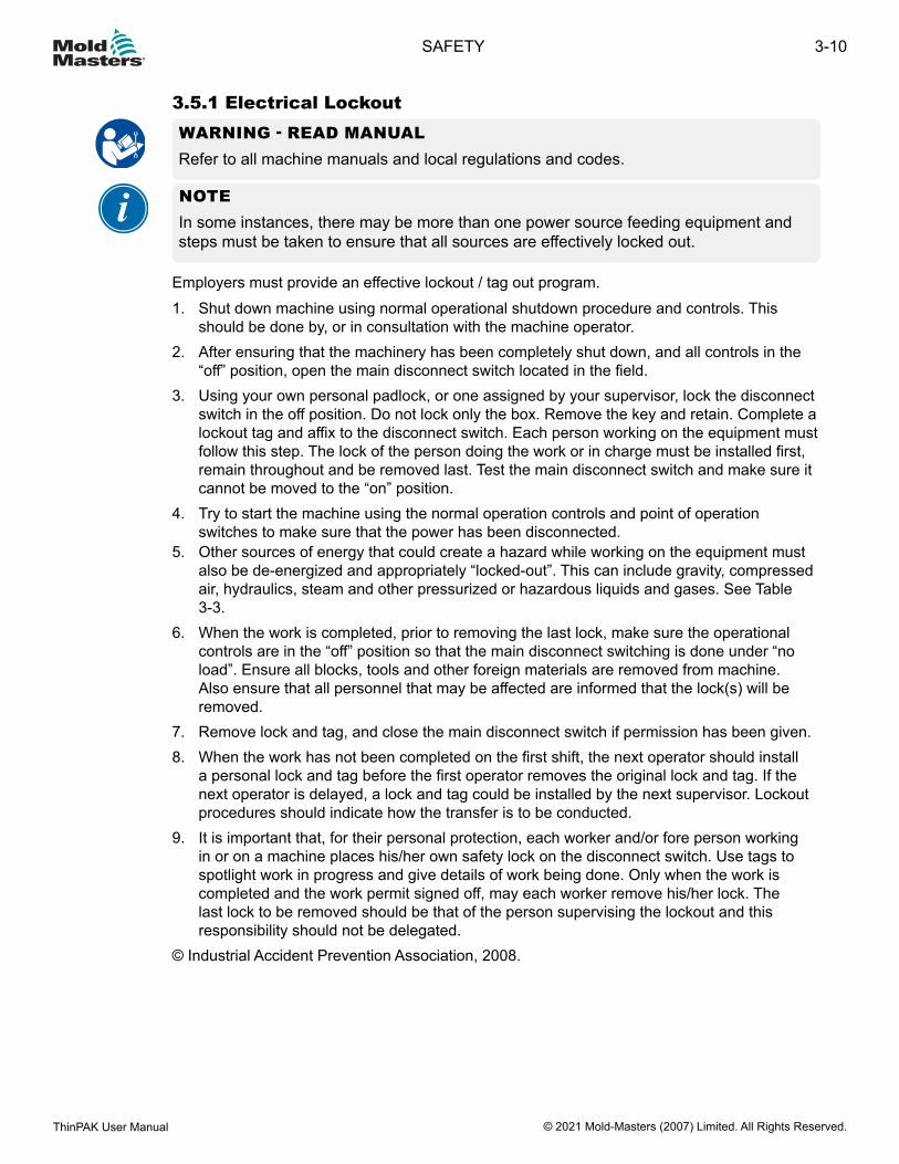
3.5.1 Electrical LockoutWARNING - READ MANUALRefer to all machine manuals and local regulations and codes.
NOTEIn some instances, there may be more than one power source feeding equipment and steps must be taken to ensure that all sources are effectively locked out.
Employers must provide an effective lockout / tag out program.1. Shut down machine using normal operational shutdown procedure and controls. This
should be done by, or in consultation with the machine operator.2. After ensuring that the machinery has been completely shut down, and all controls in the
“off” position, open the main disconnect switch located in the field.3. Using your own personal padlock, or one assigned by your supervisor, lock the disconnect
switch in the off position. Do not lock only the box. Remove the key and retain. Complete a lockout tag and affix to the disconnect switch. Each person working on the equipment must follow this step. The lock of the person doing the work or in charge must be installed first, remain throughout and be removed last. Test the main disconnect switch and make sure it cannot be moved to the “on” position.
4. Try to start the machine using the normal operation controls and point of operation switches to make sure that the power has been disconnected.
5. Other sources of energy that could create a hazard while working on the equipment must also be de-energized and appropriately “locked-out”. This can include gravity, compressed air, hydraulics, steam and other pressurized or hazardous liquids and gases. See Table 3-3.
6. When the work is completed, prior to removing the last lock, make sure the operational controls are in the “off” position so that the main disconnect switching is done under “no load”. Ensure all blocks, tools and other foreign materials are removed from machine. Also ensure that all personnel that may be affected are informed that the lock(s) will be removed.
7. Remove lock and tag, and close the main disconnect switch if permission has been given.8. When the work has not been completed on the first shift, the next operator should install
a personal lock and tag before the first operator removes the original lock and tag. If the next operator is delayed, a lock and tag could be installed by the next supervisor. Lockout procedures should indicate how the transfer is to be conducted.
9. It is important that, for their personal protection, each worker and/or fore person working in or on a machine places his/her own safety lock on the disconnect switch. Use tags to spotlight work in progress and give details of work being done. Only when the work is completed and the work permit signed off, may each worker remove his/her lock. The last lock to be removed should be that of the person supervising the lockout and this responsibility should not be delegated.
© Industrial Accident Prevention Association, 2008.
3-10
© 2021 Mold-Masters (2007) Limited. All Rights Reserved.
SAFETY
ThinPAK User Manual
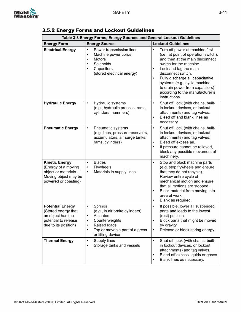
3.5.2 Energy Forms and Lockout GuidelinesTable 3-3 Energy Forms, Energy Sources and General Lockout Guidelines
Energy Form Energy Source Lockout GuidelinesElectrical Energy • Power transmission lines
• Machine power cords• Motors• Solenoids• Capacitors
(stored electrical energy)
• Turn off power at machine first (i.e., at point of operation switch), and then at the main disconnect switch for the machine.
• Lock and tag the main disconnect switch.
• Fully discharge all capacitative systems (e.g., cycle machine to drain power from capacitors) according to the manufacturer’s instructions.
Hydraulic Energy • Hydraulic systems (e.g., hydraulic presses, rams, cylinders, hammers)
• Shut off, lock (with chains, built-in lockout devices, or lockout attachments) and tag valves.
• Bleed off and blank lines as necessary.
Pneumatic Energy • Pneumatic systems (e.g.,lines, pressure reservoirs, accumulators, air surge tanks, rams, cylinders)
• Shut off, lock (with chains, built-in lockout devices, or lockout attachments) and tag valves.
• Bleed off excess air.• If pressure cannot be relieved,
block any possible movement of machinery.
Kinetic Energy(Energy of a moving object or materials. Moving object may be powered or coasting)
• Blades• Flywheels• Materials in supply lines
• Stop and block machine parts (e.g. stop flywheels and ensure that they do not recycle). Review entire cycle of mechanical motion and ensure that all motions are stopped.
• Block material from moving into area of work.
• Blank as required.Potential Energy(Stored energy that an object has the potential to release due to its position)
• Springs (e.g., in air brake cylinders)
• Actuators• Counterweights• Raised loads• Top or movable part of a press
or lifting device
• If possible, lower all suspended parts and loads to the lowest (rest) position.
• Block parts that might be moved by gravity.
• Release or block spring energy.
Thermal Energy • Supply lines• Storage tanks and vessels
• Shut off, lock (with chains, built-in lockout devices, or lockout attachments) and tag valves.
• Bleed off excess liquids or gases.• Blank lines as necessary.
3-11SAFETY
ThinPAK User Manual © 2021 Mold-Masters (2007) Limited. All Rights Reserved.
3.6 DisposalWARNING Mold-Masters declines any responsibility for personal injury or personal damage arising from reuse of the individual components, if these parts are used other than for the original and proper intended purpose.1. Hot Runner and system components must be disconnected from the power supply fully and properly before disposal (electricity, hydraulics, pneumatics and cooling).2. Ensure that the system to be disposed of is free from fluids. In the case of hydraulic needle valve systems, drain the oil from the lines and cylinders and dispose it in an environmentally responsible manner.3. The electrical components are to be dismantled, separating them accordingly environmental friendly and disposed as hazardous waste if necessary.4. Remove the wiring. The electronic components are to be disposed in accordance with the national electric scrap ordinance.5. The metal parts are to be returned for metal recycling (waste metal and scrap trade). The instructions of the corresponding waste disposal company are to be observed in this case.
Recycling of the materials occupies a forefront position during the disposal process.
3-12
© 2021 Mold-Masters (2007) Limited. All Rights Reserved.
SAFETY
ThinPAK User Manual

3.7 Hot Runner Safety HazardsWARNING• The equipment supplied is subjected to high injection pressures and high
temperatures.• Ensure that extreme caution is observed in the operation and maintenance of the Hot
Runner system and the injection molding machines.• Do not operate the equipment with unconfined long hair, loose clothing or jewelry,
including name badges, neckties, etc. These may get caught by the moving belt mechanism and can cause death or serious injury.
• Never disable or bypass a safety device.• All operators should wear personal protective equipment, such as face shields, and
use heat resistant gloves when working around the feed throat, purging the machine or cleaning the gates of the mold.
• Check frequently for possible oil or water leaks. Stop the machine and make repairs.• Do not look directly into the feed throat of a hopper. Unexpected release of resin may
cause serious burns. Use a mirror. Failure to do so may cause serious injury.• Remove purgings from the machine immediately. Never directly handle plastic
purgings or drool until they have completely cooled. Purgings may appear solid but may still be hot and cause serious injury.
• Some plastics develop gases that may be dangerous to personal health. Follow the plastics supplier’s recommendations. Review their material safety data sheet. Ensure the molding area is well ventilated.
• Never touch or inspect the timing belt when power is on and motor and controller are connected. Unplug the controller before any maintenance.
• Always cover E-Drive belt area / molding machine drop out area / bench top with a proper protective cover before any bench test or in-mold testing.
• High voltage and amperage cables are connected to the controller (220 VAC). There is also a high voltage cable connection between the servo motor and controller.
• Always unplug the controller before performing any maintenance work.• Hoses fitted to the mold will contain high or low temperature fluids or air under
high pressure. The operator must shut down and lockout these systems as well as relieving any pressure before performing any work with these hoses.
• Never perform any work on the mold unless the hydraulic pump has been stopped.• High voltage and amperage cables are connected to the mold. Electric power must be
shut off prior to installing or removing any cables.
3-13SAFETY
ThinPAK User Manual © 2021 Mold-Masters (2007) Limited. All Rights Reserved.
WARNING• Water and / or hydraulics on the mold may be in close proximity to electrical
connections and equipment. Water leakage may cause an electrical short circuit. Hydraulic fluid leakage may cause a fire hazard. Always keep water and / or hydraulic hoses and fittings in good condition to avoid leaks.
• Make sure the lifting eyebolt, lifting chain and crane are rated to adequately support the weight of the plate(s). Failure to do so can cause a serious injury.
• All maintenance on Mold-Masters products should be performed by properly trained personnel based on local law or regulation requirements.
• Ensure proper grounding of all electrical products before performing any maintenance to avoid potential risk of electrical shock.
• Make sure the machine has been locked out and tagged out in accordance to the machine’s documented procedures. Failure to do so may lead to serious injury or death.
• Check that all coolant, hydraulic and air lines as well as electrical cables will not interfere with the moving parts of the mold, machine or robot. The lines must be of sufficient length so that they will not strain or pinch when the mold halves separate.
• For water cooling nozzle jacket, coolant must be maintained with the proper mixture to prevent corrosion and circuit blockage.
• Care must be taken to ensure the nozzle terminal ends do not come in contact with the hydraulic fluid. The nozzles may short out or become damaged.
• Do not mix electrical power cables with thermocouple extension cables. They are not designed to carry the power load or list accurate temperature readings in each other’s application.
3-14
© 2021 Mold-Masters (2007) Limited. All Rights Reserved.
SAFETY
ThinPAK User Manual
CAUTIONAll Mold-Masters heated components are manufactured to standards that ensure safe and reliable operation provided that the following precautions are met:• To maximize heater element and component life, the temperature must be controlled
and maintained within safe operating limits. Mold-Masters strongly recommends individual control of each heated component, including heater plates, with a reliable temperature controller that includes soft-start protection.
• Always operate the system using correctly installed “J” type thermocouples connected to a reliable temperature controller with soft-start protection.
• Avoid running the system for long periods on manual control.• Use caution when applying power in manual mode. Use minimum heat required for
the process to avoid overheating and possible damage to components.• Always replace pinched or damaged thermocouples.• When grouping heated components together and controlling more than one load
from a single thermocouple, make sure that the components are of similar material, wattage, size and are exposed to the same thermal conditions.
• When replacing heater plates or other heated components always replace with Mold-Masters components of the same type and install as originally specified on Mold-Masters General Assembly drawings.
CAUTION
3-15SAFETY
ThinPAK User Manual © 2021 Mold-Masters (2007) Limited. All Rights Reserved.
Section 4 - PreparationWARNINGEnsure that you have fully read “Section 3 - Safety” before unpacking, cleaning or assembling parts of the Hot Runner system.
The following section is a step-by-step guide to prepare your Mold-Masters system for use.
4.1 Tools RequiredDepending on the size and complexity of your Hot Runner system, you will require most of the tools and materials listed below.
• Allen keys: Depending on system, set of metric or imperial size keys to use 4, 5, 6, 8 and 10 mm (0.16, 0.20, 0.24, 0.31 and 0.39 in.) on cap screws
• Nickel based anti-seize compound: to prevent oxidation of screw threads that could cause screws to seize with high temperatures
• Solvents (denatured alcohol): for removal of rust inhibitors• Calibrated torque wrench: for consistent screw pressure throughout the system• Pliers: for general assembly work• Circlip pliers: to remove and install circlip in valve systems• Micrometer: 0-150 mm (0-5.9 in.) to check system part and plate thickness• Depth micrometer: to check bore depths• Slot head screw driver: used in installing thermocouples and ground wires• Slot head screw driver (small): used in fastening electrical wires to connectors• Crimping tool: for fastening connector pins when necessary• Wire strippers: for preparing wires• Utility knife: for cutting tape, wires etc.• Glass tape: for grouping wires into zones• Dye spotting blue compound: for checking face contact• Sockets• Lapping compound for valve gate systems• Plastic face hammer• Proper actuator installation / extraction tools
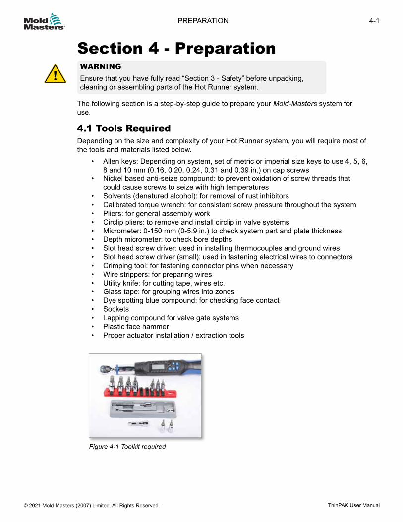
Figure 4-1 Toolkit required
4-1PREPARATION
ThinPAK User Manual © 2021 Mold-Masters (2007) Limited. All Rights Reserved.
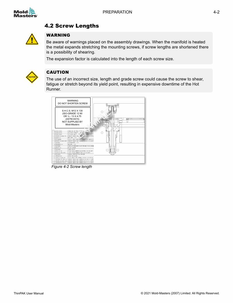
4.2 Screw LengthsWARNINGBe aware of warnings placed on the assembly drawings. When the manifold is heated the metal expands stretching the mounting screws, if screw lengths are shortened there is a possibility of shearing.The expansion factor is calculated into the length of each screw size.
CAUTIONThe use of an incorrect size, length and grade screw could cause the screw to shear, fatigue or stretch beyond its yield point, resulting in expensive downtime of the Hot Runner.
CAUTION
WARNINGDO NOT SHORTEN SCREW
S.H.C.S. M12 X 130(ISO-GRADE 12.90OR ½ - 13 X 4.75
(ASTM A574)NOT SUPPLIED BY
Mold-Masters
EXAMPLE
EXAMPLE
Figure 4-2 Screw length
4-2
© 2021 Mold-Masters (2007) Limited. All Rights Reserved.
PREPARATION
ThinPAK User Manual
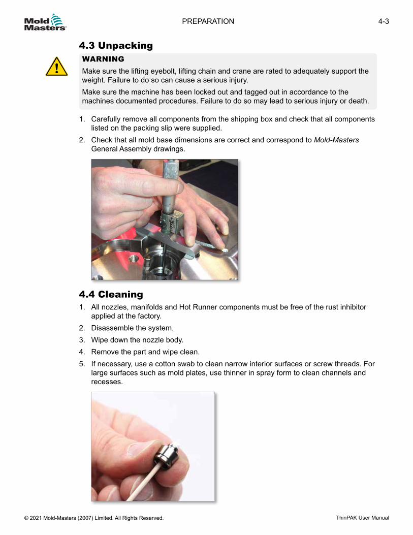
4.3 UnpackingWARNINGMake sure the lifting eyebolt, lifting chain and crane are rated to adequately support the weight. Failure to do so can cause a serious injury.Make sure the machine has been locked out and tagged out in accordance to the machines documented procedures. Failure to do so may lead to serious injury or death.
1. Carefully remove all components from the shipping box and check that all components listed on the packing slip were supplied.
2. Check that all mold base dimensions are correct and correspond to Mold-Masters General Assembly drawings.
4.4 Cleaning1. All nozzles, manifolds and Hot Runner components must be free of the rust inhibitor
applied at the factory.2. Disassemble the system.3. Wipe down the nozzle body.4. Remove the part and wipe clean.5. If necessary, use a cotton swab to clean narrow interior surfaces or screw threads. For
large surfaces such as mold plates, use thinner in spray form to clean channels and recesses.
4-3PREPARATION
ThinPAK User Manual © 2021 Mold-Masters (2007) Limited. All Rights Reserved.
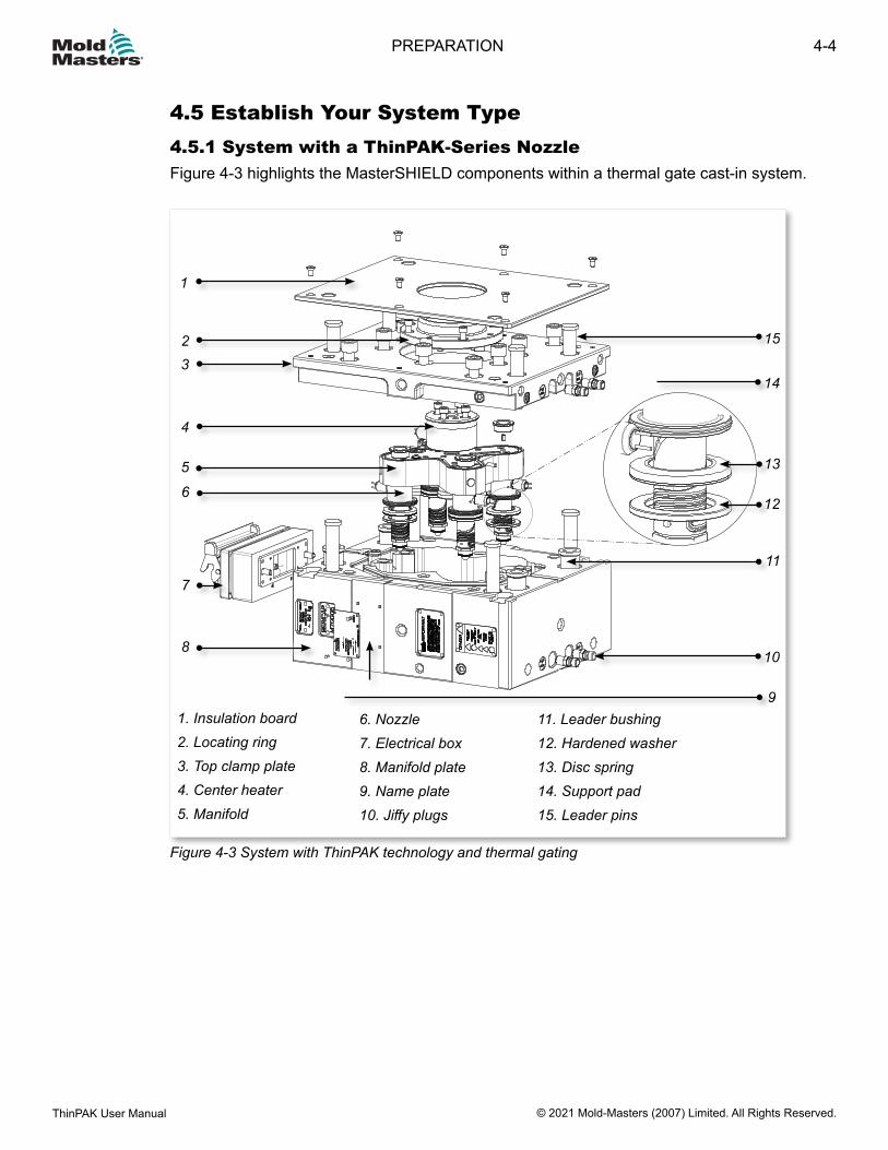
4.5 Establish Your System Type4.5.1 System with a ThinPAK-Series NozzleFigure 4-3 highlights the MasterSHIELD components within a thermal gate cast-in system.
Figure 4-3 System with ThinPAK technology and thermal gating
23
4
1
5
6
7
8
15
14
13
12
11
10
91. Insulation board2. Locating ring3. Top clamp plate4. Center heater5. Manifold
6. Nozzle7. Electrical box8. Manifold plate9. Name plate10. Jiffy plugs
11. Leader bushing12. Hardened washer13. Disc spring14. Support pad15. Leader pins
4-4
© 2021 Mold-Masters (2007) Limited. All Rights Reserved.
PREPARATION
ThinPAK User Manual
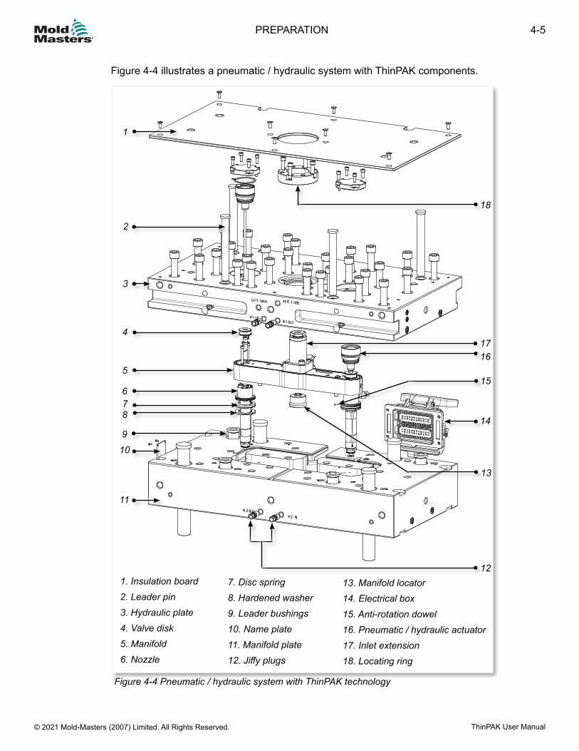
Figure 4-4 illustrates a pneumatic / hydraulic system with ThinPAK components.
Figure 4-4 Pneumatic / hydraulic system with ThinPAK technology
1
2
3
5
76
4
18
1716
15
12
8
9
11
14
13
10
1. Insulation board2. Leader pin3. Hydraulic plate4. Valve disk5. Manifold6. Nozzle
7. Disc spring8. Hardened washer9. Leader bushings10. Name plate11. Manifold plate12. Jiffy plugs
13. Manifold locator14. Electrical box15. Anti-rotation dowel16. Pneumatic / hydraulic actuator17. Inlet extension18. Locating ring
4-5PREPARATION
ThinPAK User Manual © 2021 Mold-Masters (2007) Limited. All Rights Reserved.
Section 5 - AssemblyWARNINGEnsure that you have fully read “Section 3 - Safety” before assembling parts of the Hot Runner system.
This section is a step-by-step guide to assembling your Mold-Masters Hot Runner system.
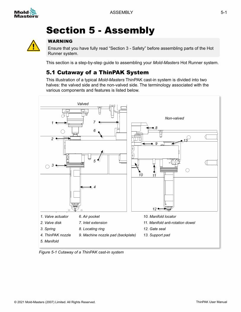
5.1 Cutaway of a ThinPAK SystemThis illustration of a typical Mold-Masters ThinPAK cast-in system is divided into two halves: the valved side and the non-valved side. The terminology associated with the various components and features is listed below.
1. Valve actuator2. Valve disk3. Spring4. ThinPAK nozzle5. Manifold
6. Air pocket7. Inlet extension8. Locating ring9. Machine nozzle pad (backplate)
10. Manifold locator11. Manifold anti-rotation dowel12. Gate seal13. Support pad
Figure 5-1 Cutaway of a ThinPAK cast-in system
Valved
1
2
3
4
5
6
7Non-valved
8
9
10 11
12
13
5-1ASSEMBLY
ThinPAK User Manual © 2021 Mold-Masters (2007) Limited. All Rights Reserved.
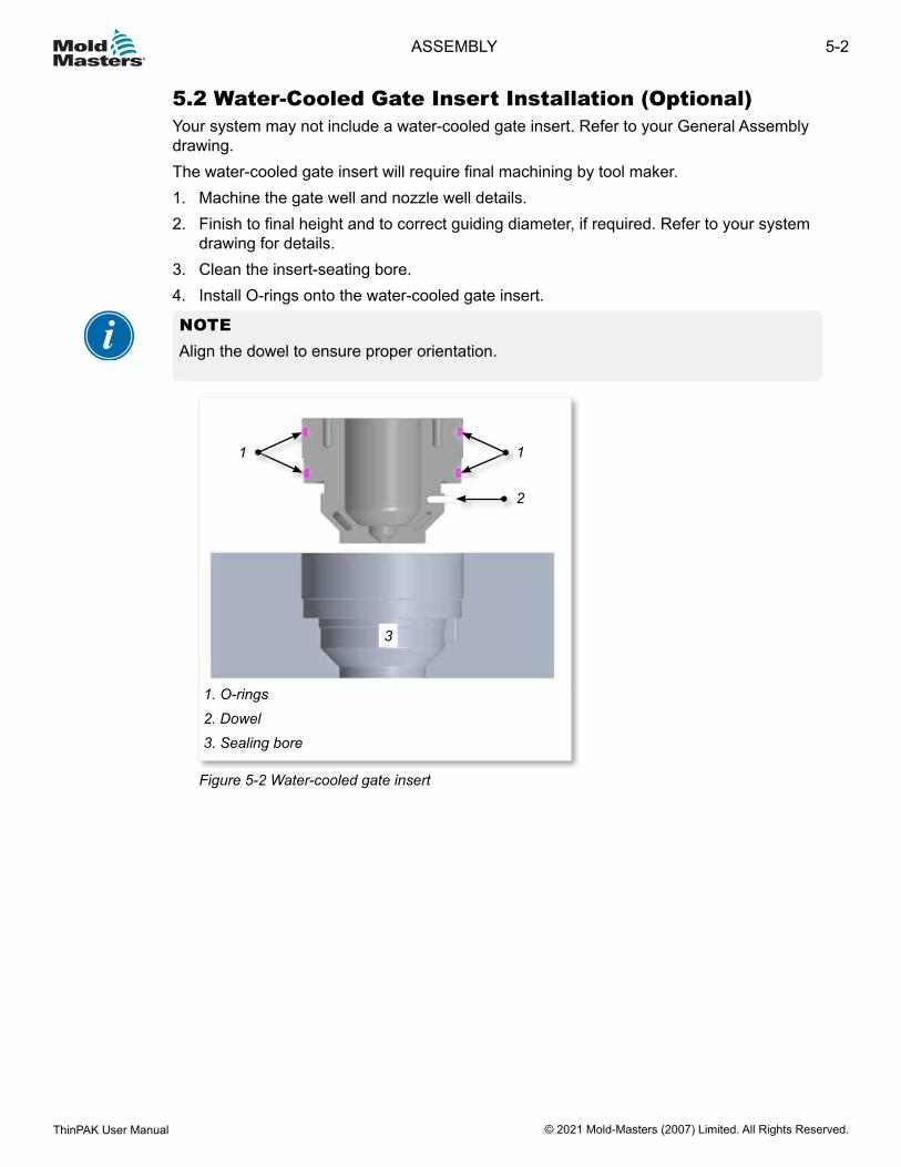
5.2 Water-Cooled Gate Insert Installation (Optional)Your system may not include a water-cooled gate insert. Refer to your General Assembly drawing.The water-cooled gate insert will require final machining by tool maker.1. Machine the gate well and nozzle well details.2. Finish to final height and to correct guiding diameter, if required. Refer to your system
drawing for details.3. Clean the insert-seating bore.4. Install O-rings onto the water-cooled gate insert.
NOTEAlign the dowel to ensure proper orientation.
1. O-rings2. Dowel3. Sealing bore
3
1
2
1
Figure 5-2 Water-cooled gate insert
5-2
© 2021 Mold-Masters (2007) Limited. All Rights Reserved.
ASSEMBLY
ThinPAK User Manual
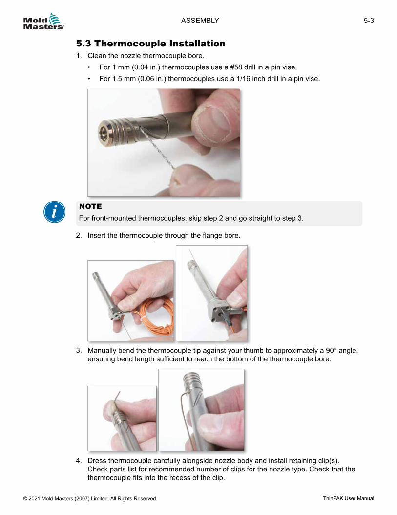
5.3 Thermocouple Installation1. Clean the nozzle thermocouple bore.
• For 1 mm (0.04 in.) thermocouples use a #58 drill in a pin vise.• For 1.5 mm (0.06 in.) thermocouples use a 1/16 inch drill in a pin vise.
NOTEFor front-mounted thermocouples, skip step 2 and go straight to step 3.
2. Insert the thermocouple through the flange bore.
3. Manually bend the thermocouple tip against your thumb to approximately a 90° angle,
ensuring bend length sufficient to reach the bottom of the thermocouple bore.
4. Dress thermocouple carefully alongside nozzle body and install retaining clip(s).
Check parts list for recommended number of clips for the nozzle type. Check that the thermocouple fits into the recess of the clip.
5-3ASSEMBLY
ThinPAK User Manual © 2021 Mold-Masters (2007) Limited. All Rights Reserved.
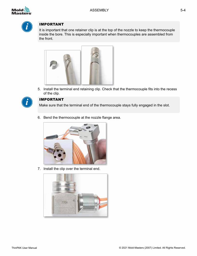
IMPORTANTIt is important that one retainer clip is at the top of the nozzle to keep the thermocouple inside the bore. This is especially important when thermocouples are assembled from the front.
5. Install the terminal end retaining clip. Check that the thermocouple fits into the recess
of the clip.
IMPORTANTMake sure that the terminal end of the thermocouple stays fully engaged in the slot.
6. Bend the thermocouple at the nozzle flange area.
7. Install the clip over the terminal end.
5-4
© 2021 Mold-Masters (2007) Limited. All Rights Reserved.
ASSEMBLY
ThinPAK User Manual
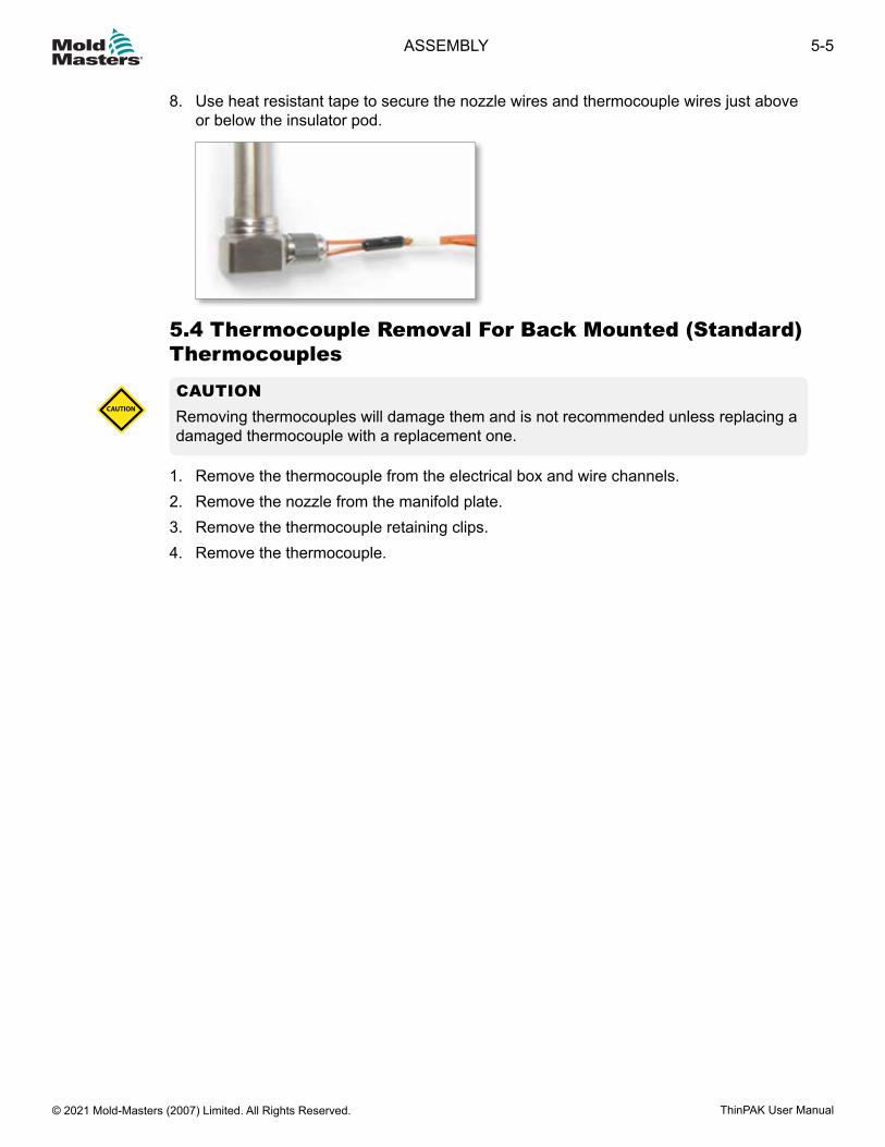
8. Use heat resistant tape to secure the nozzle wires and thermocouple wires just above or below the insulator pod.
5.4 Thermocouple Removal For Back Mounted (Standard) Thermocouples
CAUTIONRemoving thermocouples will damage them and is not recommended unless replacing a damaged thermocouple with a replacement one.
CAUTION
1. Remove the thermocouple from the electrical box and wire channels.2. Remove the nozzle from the manifold plate.3. Remove the thermocouple retaining clips.4. Remove the thermocouple.
5-5ASSEMBLY
ThinPAK User Manual © 2021 Mold-Masters (2007) Limited. All Rights Reserved.
5.5 Nozzle InsertionCAUTIONSystems with gate seals that are not accessible when fully assembled require the gate seals to be torqued hot prior to installation.The mold plate needs to be in horizontal position when inserting nozzles. Care must be taken when handling the nozzles.For liner systems, damage to the tip of a nozzle can result in gate vestige. Special care must be take with F-type, Hot Sprue and Hot Valve gating styles, where the transfer seal goes up into the part cavity. In these cases care is needed to prevent damage to the sharp edge of the gate seal and gate seal receiving bore.
CAUTION
NOTEPrior to commencing assembly verify manifold and nozzle cutouts in mold plates are to specification to ensure proper clearance to Hot Runner. Improper clearance will affect system performance.
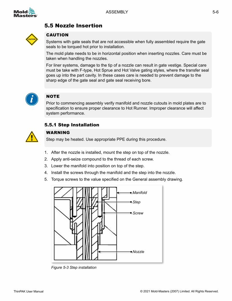
5.5.1 Step InstallationWARNINGStep may be heated. Use appropriate PPE during this procedure.
1. After the nozzle is installed, mount the step on top of the nozzle.2. Apply anti-seize compound to the thread of each screw.3. Lower the manifold into position on top of the step.4. Install the screws through the manifold and the step into the nozzle.5. Torque screws to the value specified on the General assembly drawing.
Manifold
Screw
Step
Nozzle
Figure 5-3 Step installation
5-6
© 2021 Mold-Masters (2007) Limited. All Rights Reserved.
ASSEMBLY
ThinPAK User Manual
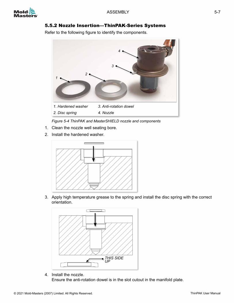
5.5.2 Nozzle Insertion—ThinPAK-Series SystemsRefer to the following figure to identify the components.
4
3
21
1. Hardened washer2. Disc spring
3. Anti-rotation dowel4. Nozzle
Figure 5-4 ThinPAK and MasterSHIELD nozzle and components
1. Clean the nozzle well seating bore.2. Install the hardened washer.
3. Apply high temperature grease to the spring and install the disc spring with the correct orientation.
THIS SIDE UP
4. Install the nozzle. Ensure the anti-rotation dowel is in the slot cutout in the manifold plate.
5-7ASSEMBLY
ThinPAK User Manual © 2021 Mold-Masters (2007) Limited. All Rights Reserved.
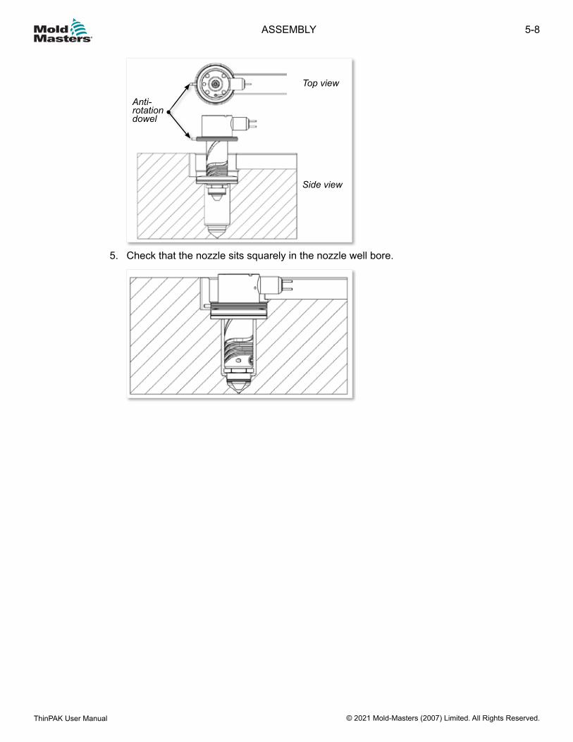
Top view
Side view
Anti-rotation dowel
5. Check that the nozzle sits squarely in the nozzle well bore.
5-8
© 2021 Mold-Masters (2007) Limited. All Rights Reserved.
ASSEMBLY
ThinPAK User Manual
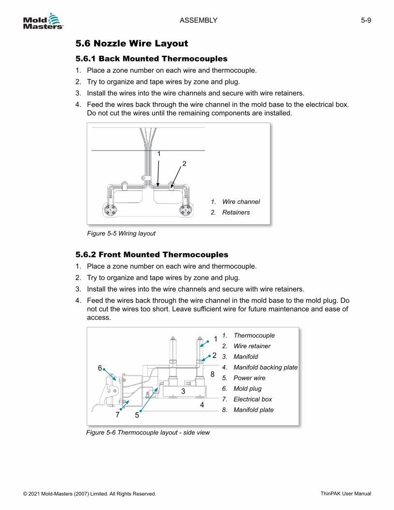
5.6 Nozzle Wire Layout5.6.1 Back Mounted Thermocouples1. Place a zone number on each wire and thermocouple.2. Try to organize and tape wires by zone and plug.3. Install the wires into the wire channels and secure with wire retainers.4. Feed the wires back through the wire channel in the mold base to the electrical box.
Do not cut the wires until the remaining components are installed.
12
1. Wire channel2. Retainers
Figure 5-5 Wiring layout
5.6.2 Front Mounted Thermocouples1. Place a zone number on each wire and thermocouple.2. Try to organize and tape wires by zone and plug.3. Install the wires into the wire channels and secure with wire retainers.4. Feed the wires back through the wire channel in the mold base to the mold plug. Do
not cut the wires too short. Leave sufficient wire for future maintenance and ease of access.
1
7
6
54
3
2
8
1. Thermocouple2. Wire retainer3. Manifold4. Manifold backing plate5. Power wire6. Mold plug7. Electrical box8. Manifold plate
Figure 5-6 Thermocouple layout - side view
5-9ASSEMBLY
ThinPAK User Manual © 2021 Mold-Masters (2007) Limited. All Rights Reserved.
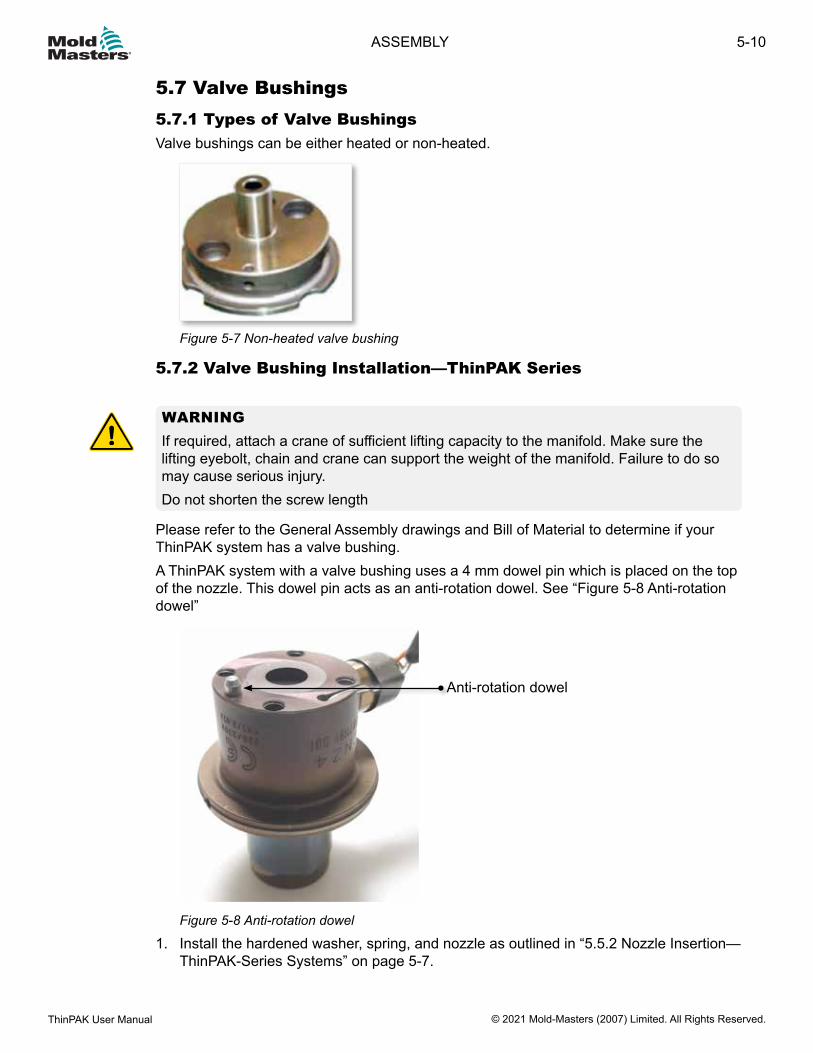
5.7 Valve Bushings5.7.1 Types of Valve BushingsValve bushings can be either heated or non-heated.
Figure 5-7 Non-heated valve bushing
5.7.2 Valve Bushing Installation—ThinPAK Series
WARNINGIf required, attach a crane of sufficient lifting capacity to the manifold. Make sure the lifting eyebolt, chain and crane can support the weight of the manifold. Failure to do so may cause serious injury.Do not shorten the screw length
Please refer to the General Assembly drawings and Bill of Material to determine if your ThinPAK system has a valve bushing.A ThinPAK system with a valve bushing uses a 4 mm dowel pin which is placed on the top of the nozzle. This dowel pin acts as an anti-rotation dowel. See “Figure 5-8 Anti-rotation dowel”
Anti-rotation dowel
Figure 5-8 Anti-rotation dowel
1. Install the hardened washer, spring, and nozzle as outlined in “5.5.2 Nozzle Insertion—ThinPAK-Series Systems” on page 5-7.
5-10
© 2021 Mold-Masters (2007) Limited. All Rights Reserved.
ASSEMBLY
ThinPAK User Manual
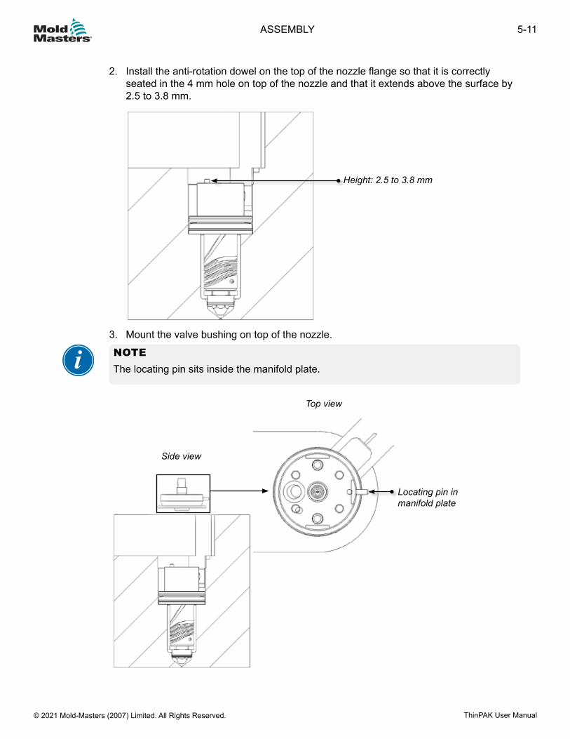
2. Install the anti-rotation dowel on the top of the nozzle flange so that it is correctly seated in the 4 mm hole on top of the nozzle and that it extends above the surface by 2.5 to 3.8 mm.
Height: 2.5 to 3.8 mm
3. Mount the valve bushing on top of the nozzle.
NOTEThe locating pin sits inside the manifold plate.
Locating pin in manifold plate
Side view
Top view
5-11ASSEMBLY
ThinPAK User Manual © 2021 Mold-Masters (2007) Limited. All Rights Reserved.
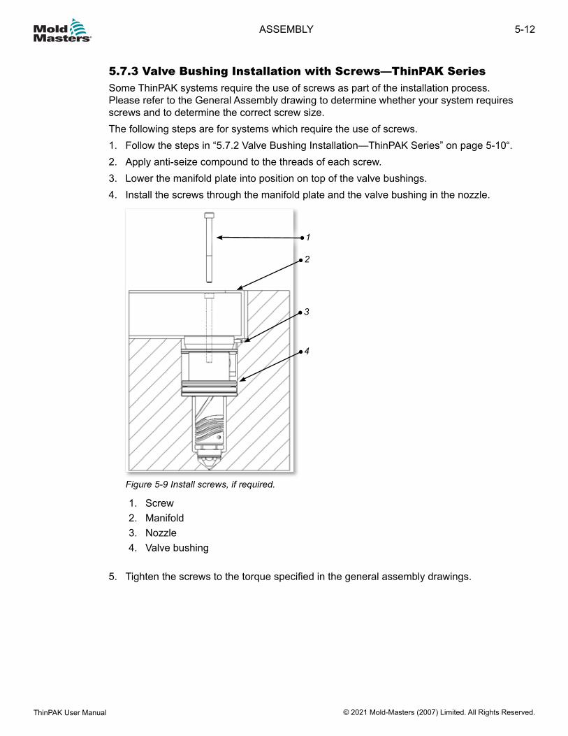
5.7.3 Valve Bushing Installation with Screws—ThinPAK SeriesSome ThinPAK systems require the use of screws as part of the installation process. Please refer to the General Assembly drawing to determine whether your system requires screws and to determine the correct screw size.The following steps are for systems which require the use of screws.1. Follow the steps in “5.7.2 Valve Bushing Installation—ThinPAK Series” on page 5-10“.2. Apply anti-seize compound to the threads of each screw.3. Lower the manifold plate into position on top of the valve bushings.4. Install the screws through the manifold plate and the valve bushing in the nozzle.
1
2
3
4
Figure 5-9 Install screws, if required.
1. Screw2. Manifold3. Nozzle4. Valve bushing
5. Tighten the screws to the torque specified in the general assembly drawings.
5-12
© 2021 Mold-Masters (2007) Limited. All Rights Reserved.
ASSEMBLY
ThinPAK User Manual
5.8 Mount the ManifoldIntroductionThere are three methods used to locate the manifold:1. Manifold locator2. Manifold locating dowel pin3. Manifold and slot locator
5.8.1 Manifold Locator
WARNINGMake sure the lifting eyebolt, chain and crane can support the weight of the manifold. Failure to do so may cause serious injury.
Depending on your system, the manifold locator may require final grinding.
NOTERefer to the General Assembly drawing for details of your particular system.
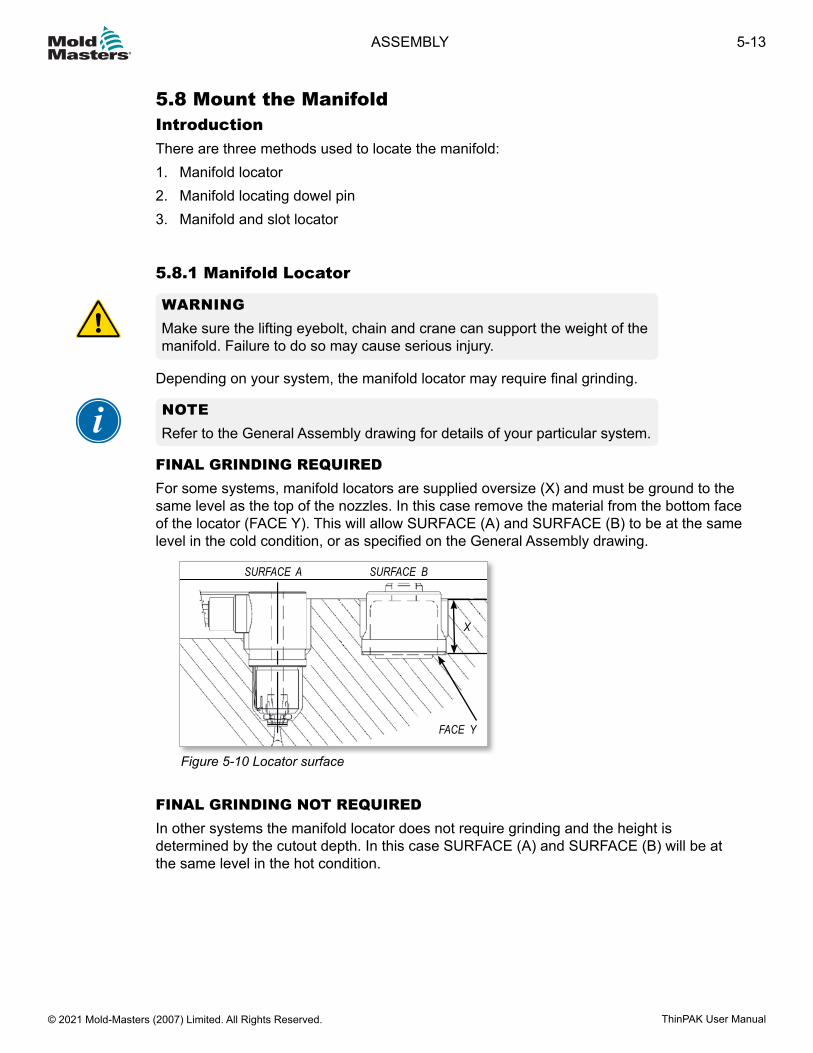
FINAL GRINDING REQUIREDFor some systems, manifold locators are supplied oversize (X) and must be ground to the same level as the top of the nozzles. In this case remove the material from the bottom face of the locator (FACE Y). This will allow SURFACE (A) and SURFACE (B) to be at the same level in the cold condition, or as specified on the General Assembly drawing.
SURFACE A SURFACE B
FACE Y
X
Figure 5-10 Locator surface
FINAL GRINDING NOT REQUIREDIn other systems the manifold locator does not require grinding and the height is determined by the cutout depth. In this case SURFACE (A) and SURFACE (B) will be at the same level in the hot condition.
5-13ASSEMBLY
ThinPAK User Manual © 2021 Mold-Masters (2007) Limited. All Rights Reserved.
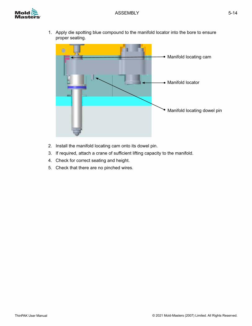
1. Apply die spotting blue compound to the manifold locator into the bore to ensure proper seating.
Manifold locator
Manifold locating cam
Manifold locating dowel pin
2. Install the manifold locating cam onto its dowel pin.3. If required, attach a crane of sufficient lifting capacity to the manifold.4. Check for correct seating and height.5. Check that there are no pinched wires.
5-14
© 2021 Mold-Masters (2007) Limited. All Rights Reserved.
ASSEMBLY
ThinPAK User Manual
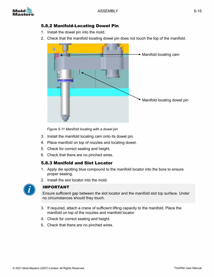
5.8.2 Manifold-Locating Dowel Pin1. Install the dowel pin into the mold.2. Check that the manifold locating dowel pin does not touch the top of the manifold.
Manifold locating cam
Manifold locating dowel pin
Figure 5-11 Manifold locating with a dowel pin
3. Install the manifold locating cam onto its dowel pin.4. Place manifold on top of nozzles and locating dowel.5. Check for correct seating and height.6. Check that there are no pinched wires.
5.8.3 Manifold and Slot Locator1. Apply die spotting blue compound to the manifold locator into the bore to ensure
proper seating.2. Install the slot locator into the mold.
IMPORTANTEnsure sufficient gap between the slot locator and the manifold slot top surface. Under no circumstances should they touch.
3. If required, attach a crane of sufficient lifting capacity to the manifold. Place the manifold on top of the nozzles and manifold locator.
4. Check for correct seating and height.5. Check that there are no pinched wires.
5-15ASSEMBLY
ThinPAK User Manual © 2021 Mold-Masters (2007) Limited. All Rights Reserved.
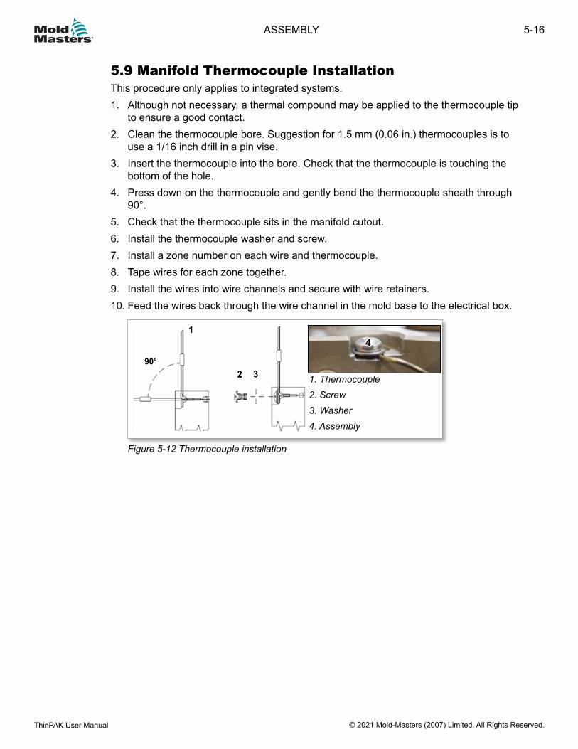
5.9 Manifold Thermocouple InstallationThis procedure only applies to integrated systems.1. Although not necessary, a thermal compound may be applied to the thermocouple tip
to ensure a good contact.2. Clean the thermocouple bore. Suggestion for 1.5 mm (0.06 in.) thermocouples is to
use a 1/16 inch drill in a pin vise.3. Insert the thermocouple into the bore. Check that the thermocouple is touching the
bottom of the hole.4. Press down on the thermocouple and gently bend the thermocouple sheath through
90°.5. Check that the thermocouple sits in the manifold cutout.6. Install the thermocouple washer and screw.7. Install a zone number on each wire and thermocouple.8. Tape wires for each zone together.9. Install the wires into wire channels and secure with wire retainers.10. Feed the wires back through the wire channel in the mold base to the electrical box.
4
1. Thermocouple2. Screw3. Washer4. Assembly
1
2 390°
Figure 5-12 Thermocouple installation
5-16
© 2021 Mold-Masters (2007) Limited. All Rights Reserved.
ASSEMBLY
ThinPAK User Manual
5.10 Main ManifoldsManifolds distribute melt from the inlet component to one or more submanifolds. If you have a submanifold configuration, follow these instructions. This system will have one of two configurations for inlet seals.Refer to the General Assembly drawing to determine which applies.• Inlet seal without step• Inlet seal with step
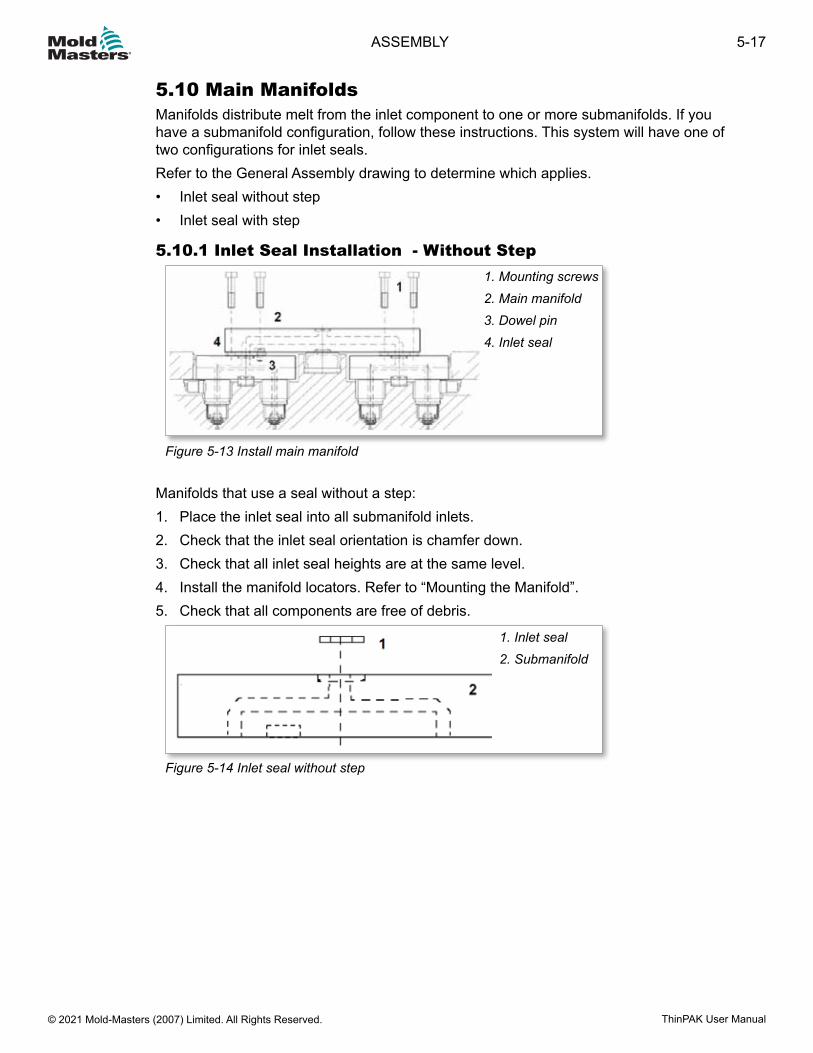
5.10.1 Inlet Seal Installation - Without Step1. Mounting screws2. Main manifold3. Dowel pin4. Inlet seal
Figure 5-13 Install main manifold
Manifolds that use a seal without a step:1. Place the inlet seal into all submanifold inlets.2. Check that the inlet seal orientation is chamfer down.3. Check that all inlet seal heights are at the same level.4. Install the manifold locators. Refer to “Mounting the Manifold”.5. Check that all components are free of debris.
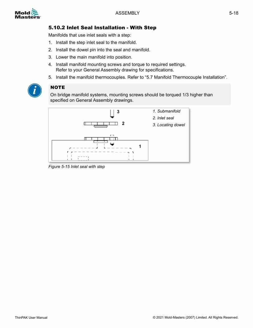
1. Inlet seal2. Submanifold
Figure 5-14 Inlet seal without step
5-17ASSEMBLY
ThinPAK User Manual © 2021 Mold-Masters (2007) Limited. All Rights Reserved.
5.10.2 Inlet Seal Installation - With StepManifolds that use inlet seals with a step:1. Install the step inlet seal to the manifold.2. Install the dowel pin into the seal and manifold.3. Lower the main manifold into position.4. Install manifold mounting screws and torque to required settings.
Refer to your General Assembly drawing for specifications.5. Install the manifold thermocouples. Refer to “5.7 Manifold Thermocouple Installation”.
NOTEOn bridge manifold systems, mounting screws should be torqued 1/3 higher than specified on General Assembly drawings.
1. Submanifold2. Inlet seal3. Locating dowel
Figure 5-15 Inlet seal with step
5-18
© 2021 Mold-Masters (2007) Limited. All Rights Reserved.
ASSEMBLY
ThinPAK User Manual
5.11 Support Bushing InstallationWARNINGMake sure the lifting eyebolt, chain and crane can support the weight of the manifold. Failure to do so may cause serious injury.
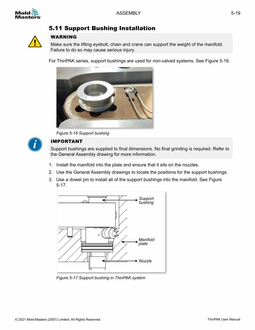
For ThinPAK series, support bushings are used for non-valved systems. See Figure 5-16.
Figure 5-16 Support bushing
IMPORTANTSupport bushings are supplied to final dimensions. No final grinding is required. Refer to the General Assembly drawing for more information.
1. Install the manifold into the plate and ensure that it sits on the nozzles.2. Use the General Assembly drawings to locate the positions for the support bushings.3. Use a dowel pin to install all of the support bushings into the manifold. See Figure
5-17.
Nozzle
Manifold plate
Support bushing
Figure 5-17 Support bushing in ThinPAK system
5-19ASSEMBLY
ThinPAK User Manual © 2021 Mold-Masters (2007) Limited. All Rights Reserved.
5.12 Valve Disk InstallationWARNINGMake sure the lifting eyebolt, chain and crane can support the weight of the manifold. Failure to do so may cause serious injury.
IMPORTANTValve disks are supplied to final dimensions. No final grinding is required.Some ThinPAK systems require the use of screws as part of the installation process. Please refer to the General Assembly drawing to determine if your system requires screws.
Spring dowel
Valve disk
Manifold plate
Nozzle
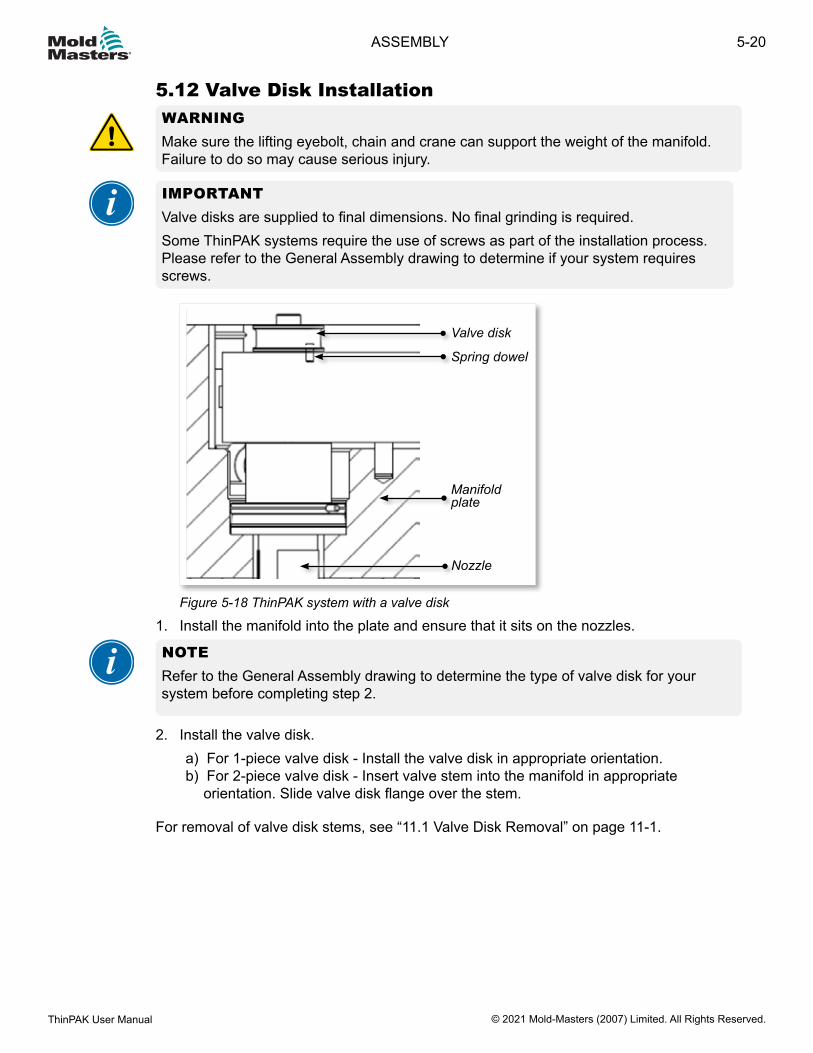
Figure 5-18 ThinPAK system with a valve disk
1. Install the manifold into the plate and ensure that it sits on the nozzles.
NOTERefer to the General Assembly drawing to determine the type of valve disk for your system before completing step 2.
2. Install the valve disk.a) For 1-piece valve disk - Install the valve disk in appropriate orientation.b) For 2-piece valve disk - Insert valve stem into the manifold in appropriate
orientation. Slide valve disk flange over the stem.
For removal of valve disk stems, see “11.1 Valve Disk Removal” on page 11-1.
5-20
© 2021 Mold-Masters (2007) Limited. All Rights Reserved.
ASSEMBLY
ThinPAK User Manual
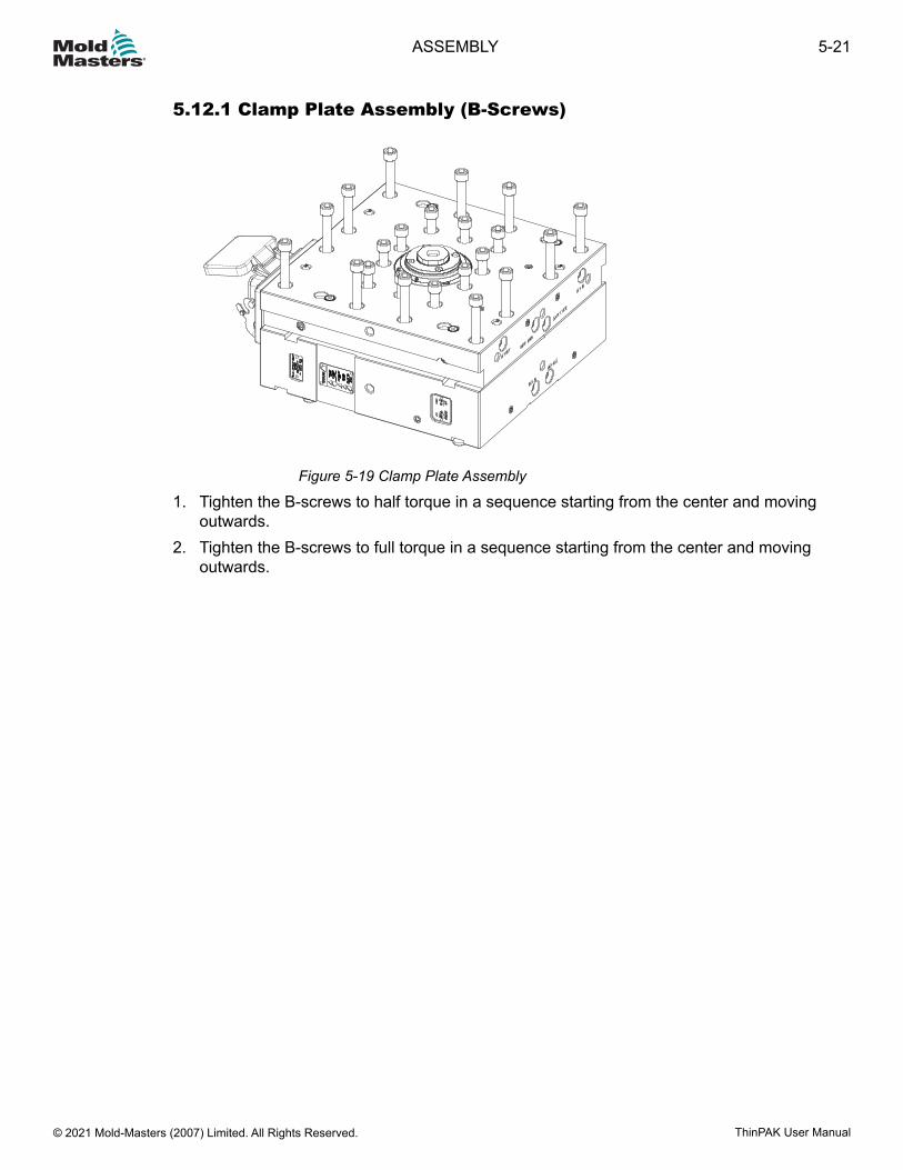
5.12.1 Clamp Plate Assembly (B-Screws)
Figure 5-19 Clamp Plate Assembly
1. Tighten the B-screws to half torque in a sequence starting from the center and moving outwards.
2. Tighten the B-screws to full torque in a sequence starting from the center and moving outwards.
5-21ASSEMBLY
ThinPAK User Manual © 2021 Mold-Masters (2007) Limited. All Rights Reserved.
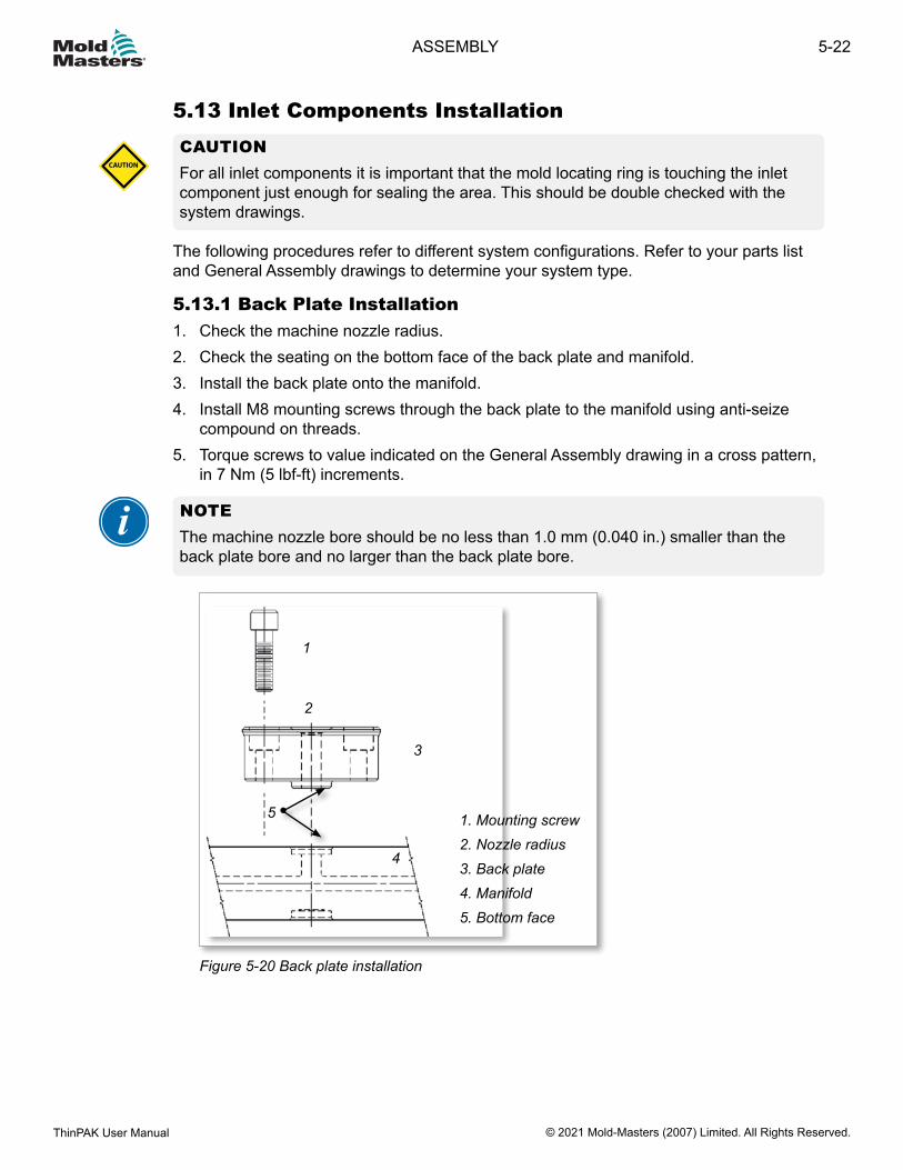
5.13 Inlet Components InstallationCAUTIONFor all inlet components it is important that the mold locating ring is touching the inlet component just enough for sealing the area. This should be double checked with the system drawings.
CAUTION
The following procedures refer to different system configurations. Refer to your parts list and General Assembly drawings to determine your system type.
5.13.1 Back Plate Installation1. Check the machine nozzle radius.2. Check the seating on the bottom face of the back plate and manifold.3. Install the back plate onto the manifold.4. Install M8 mounting screws through the back plate to the manifold using anti-seize
compound on threads.5. Torque screws to value indicated on the General Assembly drawing in a cross pattern,
in 7 Nm (5 lbf-ft) increments.
NOTE The machine nozzle bore should be no less than 1.0 mm (0.040 in.) smaller than the back plate bore and no larger than the back plate bore.
1
2
3
4
5 1. Mounting screw2. Nozzle radius3. Back plate4. Manifold5. Bottom face
Figure 5-20 Back plate installation
5-22
© 2021 Mold-Masters (2007) Limited. All Rights Reserved.
ASSEMBLY
ThinPAK User Manual
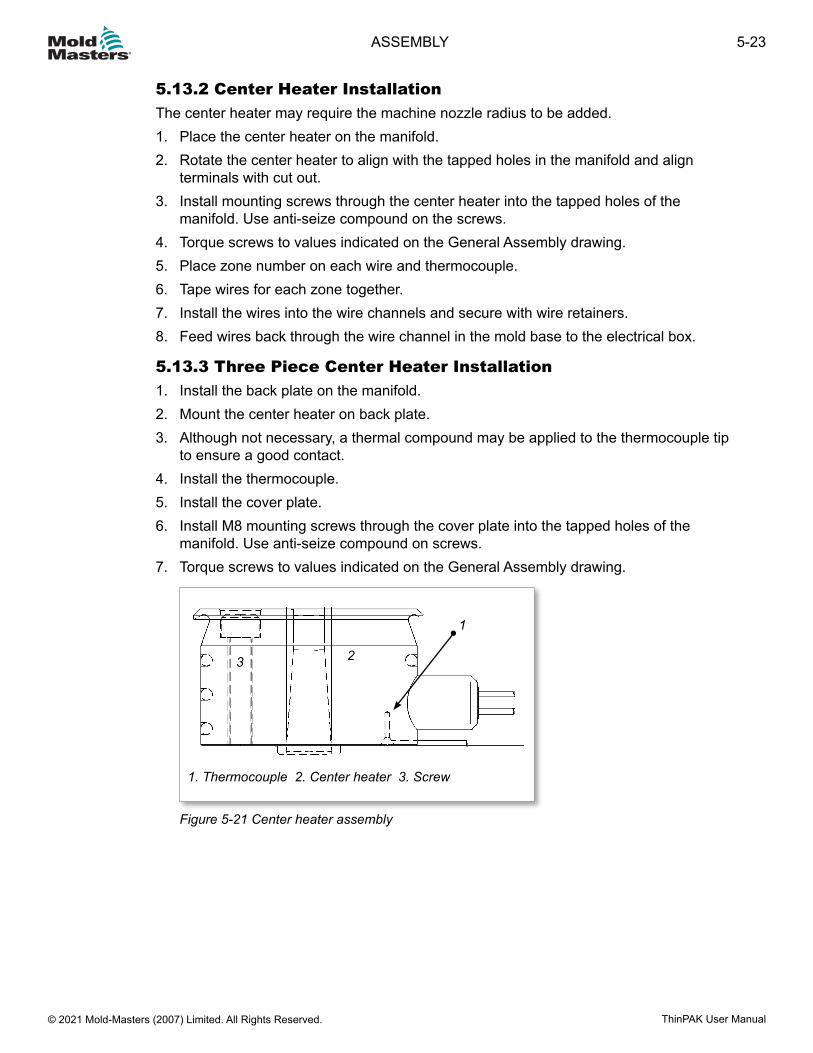
5.13.2 Center Heater InstallationThe center heater may require the machine nozzle radius to be added.1. Place the center heater on the manifold.2. Rotate the center heater to align with the tapped holes in the manifold and align
terminals with cut out.3. Install mounting screws through the center heater into the tapped holes of the
manifold. Use anti-seize compound on the screws.4. Torque screws to values indicated on the General Assembly drawing.5. Place zone number on each wire and thermocouple.6. Tape wires for each zone together.7. Install the wires into the wire channels and secure with wire retainers.8. Feed wires back through the wire channel in the mold base to the electrical box.
5.13.3 Three Piece Center Heater Installation1. Install the back plate on the manifold.2. Mount the center heater on back plate.3. Although not necessary, a thermal compound may be applied to the thermocouple tip
to ensure a good contact.4. Install the thermocouple.5. Install the cover plate.6. Install M8 mounting screws through the cover plate into the tapped holes of the
manifold. Use anti-seize compound on screws.7. Torque screws to values indicated on the General Assembly drawing.
1
23
1. Thermocouple 2. Center heater 3. Screw
Figure 5-21 Center heater assembly
5-23ASSEMBLY
ThinPAK User Manual © 2021 Mold-Masters (2007) Limited. All Rights Reserved.
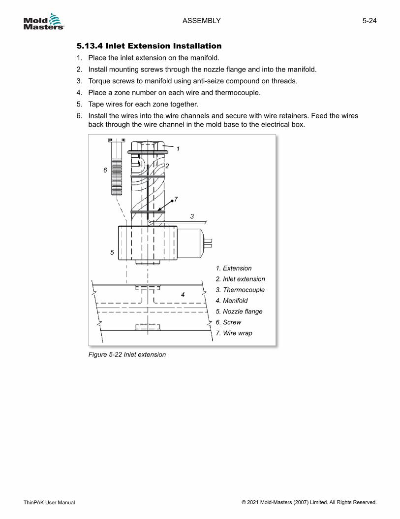
5.13.4 Inlet Extension Installation1. Place the inlet extension on the manifold.2. Install mounting screws through the nozzle flange and into the manifold.3. Torque screws to manifold using anti-seize compound on threads.4. Place a zone number on each wire and thermocouple.5. Tape wires for each zone together.6. Install the wires into the wire channels and secure with wire retainers. Feed the wires
back through the wire channel in the mold base to the electrical box.
1
2
3
4
5
6
7
1. Extension2. Inlet extension3. Thermocouple4. Manifold5. Nozzle flange6. Screw7. Wire wrap
Figure 5-22 Inlet extension
5-24
© 2021 Mold-Masters (2007) Limited. All Rights Reserved.
ASSEMBLY
ThinPAK User Manual
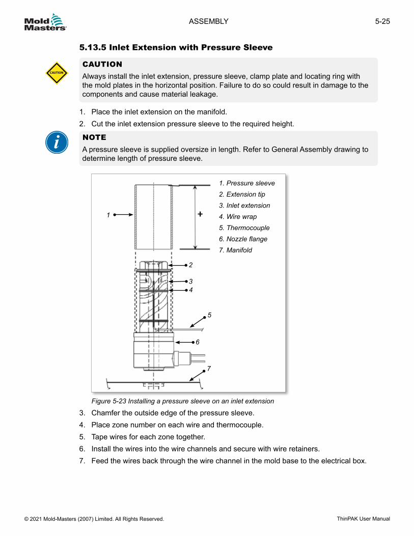
5.13.5 Inlet Extension with Pressure Sleeve
CAUTIONAlways install the inlet extension, pressure sleeve, clamp plate and locating ring with the mold plates in the horizontal position. Failure to do so could result in damage to the components and cause material leakage.
CAUTION
1. Place the inlet extension on the manifold.2. Cut the inlet extension pressure sleeve to the required height.
NOTEA pressure sleeve is supplied oversize in length. Refer to General Assembly drawing to determine length of pressure sleeve.
1
2
34
5
6
7
1. Pressure sleeve2. Extension tip3. Inlet extension4. Wire wrap5. Thermocouple6. Nozzle flange7. Manifold
Figure 5-23 Installing a pressure sleeve on an inlet extension
3. Chamfer the outside edge of the pressure sleeve.4. Place zone number on each wire and thermocouple.5. Tape wires for each zone together.6. Install the wires into the wire channels and secure with wire retainers.7. Feed the wires back through the wire channel in the mold base to the electrical box.
5-25ASSEMBLY
ThinPAK User Manual © 2021 Mold-Masters (2007) Limited. All Rights Reserved.
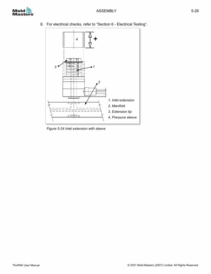
8. For electrical checks, refer to “Section 6 - Electrical Testing”.
1. Inlet extension2. Manifold3. Extension tip4. Pressure sleeve
1
2
3
4
Figure 5-24 Inlet extension with sleeve
5-26
© 2021 Mold-Masters (2007) Limited. All Rights Reserved.
ASSEMBLY
ThinPAK User Manual
Section 6 - Electrical TestingWARNINGEnsure that you have fully read “Section 3 - Safety” before beginning electrical testing.
This section contains guidelines for electrical testing of your Mold-Masters Hot Runner system. The testing is based on the following European and North American standards:• EN 60204-1 / DIN EN 60204-1 (IEC 60204-1, modified) Safety of machinery - electrical
equipment of machines• NFPA 79 Electrical Standard for Industrial MachineryThe standards themselves are the final authority for testing requirements (also any additional testing requirements from any national standards where the Hot Runner is in use).
6.1 SafetyWARNINGThe user is responsible to ensure protection against shock by indirect contact, by protective earth conductors and automatic disconnection of supply. Mold-Masters components and systems are either equipped with a protective earth conductor or there is a connector for this purpose.Before you carry out electrical work, make sure that the Hot Runner system is securely grounded. Turn the temperature control off and disconnect all electric wires coming from the mold. Failure to follow any of these steps may lead to serious injury or death.Ensure that all wiring and connection work is performed by a qualified electrician according to DIN EN 60204-1 / NFPA79.If performing work on a disassembled nozzle, it should only be connected to an electrical supply when the nozzle has been grounded or a safety isolating transformer is used.Contact with a disassembled, heated, nozzle would cause serious burns. Use a sign in a visible location indicating “Danger: Do Not Touch”. Wear protective heat-resistant gloves and a full face shield over safety glasses.
6.2 Electrical Wiring CheckWARNINGThe electricity mains should only be connected to the injection mold when all electrical connections are grounded and the mold is closed.
1. Check that each wire and thermocouple has a zone number.2. Check that wires are organized and taped together by zone and plug.3. Check all wires are secured in wire channels.4. Connect all power leads and thermocouple wires to mold plugs.
6-1ELECTRICAL TESTING
ThinPAK User Manual © 2021 Mold-Masters (2007) Limited. All Rights Reserved.
6.3 Electrical Safety TestingElectrical safety tests shall be performed according to DIN EN 60204-1, paragraph 18, and NFPA79. Testing guidelines are given below, however, the standards identified earlier in the introduction are the final authority.
6.3.1 Verify Equipment to its Technical DocumentationFirst, verify that the electrical equipment complies with its technical documentation.
6.3.2 Insulation Resistance TestMeasure the insulation resistance between each pin of the Mold-Masters power connector, in particular the heating circuit and ground.The insulation resistance is measured at 500 VDC. The insulation resistance must not be less than 1 MΩ.If this value is not reached when heating, the cause is often moisture inside the heating element, which should be removed using a control unit equipped with this function.Where a mold has not been in use for several weeks or months, it should be retested.
6-2
© 2021 Mold-Masters (2007) Limited. All Rights Reserved.
ELECTRICAL TESTING
ThinPAK User Manual
6.3.3 Verification of Conditions for Protection by Automatic Disconnection of Supply
WARNINGThe user is responsible to take protective measures against shock by indirect contact, while performing the tests.
The conditions for automatic shutdown of the supply is set at Mold-Masters and is usually set such that the protective conductor resistance between the grounding conductor connection and all of the protective earth conductor connected parts, is Maximum 0.3 Ω.In TN systems the following two checks must be made:
6.3.4 Verification of Continuity of Protective Bonding CircuitVerifies the continuity of the protective bonding circuit. The purpose of this test is to check whether all relevant touchable conductive parts are properly grounded. See the relevant requirements of the standard DIN EN 60204-1 / NPFPA79.
The protective conductor resistance is measured with a special instrument with a current between at least 0.2 A and approximately 10 A derived from an electrically separated supply source (for example SELV, see 413.1 of IEC 60364-4-41) having a maximum no-load voltage of 24 V AC or DC. The resistance must be within the expected range.
6.3.5 Verification of Fault Loop ImpedanceFault loop impedance verification and suitability of the associated overcurrent protective device.
The power supply connections and incoming external grounding connections to the Hot Runner system must be verified by inspection (usually through a temperature control device).The conditions for protection by automatic disconnection of supply must be checked by both:• Checking the impedance of the fault loop by calculation or measurement.• Confirming that the setting and characteristics of the associated overcurrent protective
device are in accordance with the requirements of the standard.For more information, see the text of the EN 60204-1/ NFPA79 standards must be verified by inspection.
6-3ELECTRICAL TESTING
ThinPAK User Manual © 2021 Mold-Masters (2007) Limited. All Rights Reserved.
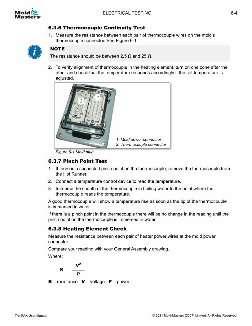
6.3.6 Thermocouple Continuity Test1. Measure the resistance between each pair of thermocouple wires on the mold’s
thermocouple connector. See Figure 6-1.
NOTEThe resistance should be between 2.5 Ω and 25 Ω.
2. To verify alignment of thermocouple in the heating element, turn on one zone after the other and check that the temperature responds accordingly if the set temperature is adjusted.
1. Mold power connector 2. Thermocouple connector
12
Figure 6-1 Mold plug
6.3.7 Pinch Point Test1. If there is a suspected pinch point on the thermocouple, remove the thermocouple from
the Hot Runner.2. Connect a temperature control device to read the temperature.3. Immerse the sheath of the thermocouple in boiling water to the point where the
thermocouple reads the temperature.A good thermocouple will show a temperature rise as soon as the tip of the thermocouple is immersed in water.If there is a pinch point in the thermocouple there will be no change in the reading until the pinch point on the thermocouple is immersed in water.
6.3.8 Heating Element CheckMeasure the resistance between each pair of heater power wires at the mold power connector.Compare your reading with your General Assembly drawing.Where:
R =V2
P
R = resistance V = voltage P = power
6-4
© 2021 Mold-Masters (2007) Limited. All Rights Reserved.
ELECTRICAL TESTING
ThinPAK User Manual
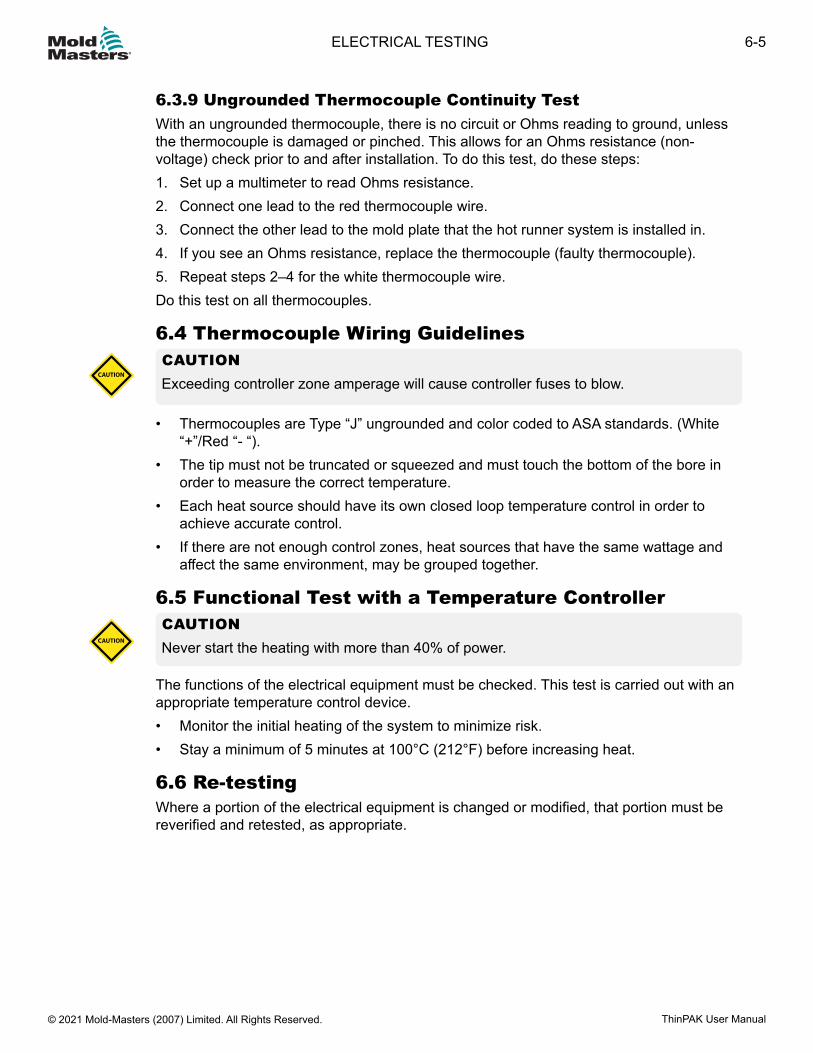
6.3.9 Ungrounded Thermocouple Continuity TestWith an ungrounded thermocouple, there is no circuit or Ohms reading to ground, unless the thermocouple is damaged or pinched. This allows for an Ohms resistance (non-voltage) check prior to and after installation. To do this test, do these steps:1. Set up a multimeter to read Ohms resistance.2. Connect one lead to the red thermocouple wire.3. Connect the other lead to the mold plate that the hot runner system is installed in.4. If you see an Ohms resistance, replace the thermocouple (faulty thermocouple).5. Repeat steps 2–4 for the white thermocouple wire.Do this test on all thermocouples.
6.4 Thermocouple Wiring GuidelinesCAUTIONExceeding controller zone amperage will cause controller fuses to blow.
CAUTION
• Thermocouples are Type “J” ungrounded and color coded to ASA standards. (White “+”/Red “- “).
• The tip must not be truncated or squeezed and must touch the bottom of the bore in order to measure the correct temperature.
• Each heat source should have its own closed loop temperature control in order to achieve accurate control.
• If there are not enough control zones, heat sources that have the same wattage and affect the same environment, may be grouped together.
6.5 Functional Test with a Temperature ControllerCAUTIONNever start the heating with more than 40% of power.CAUTION
The functions of the electrical equipment must be checked. This test is carried out with an appropriate temperature control device.• Monitor the initial heating of the system to minimize risk.• Stay a minimum of 5 minutes at 100°C (212°F) before increasing heat.
6.6 Re-testingWhere a portion of the electrical equipment is changed or modified, that portion must be reverified and retested, as appropriate.
6-5ELECTRICAL TESTING
ThinPAK User Manual © 2021 Mold-Masters (2007) Limited. All Rights Reserved.

1. Nozzle well depth (L) 2. Cavity plate 3. Manifold plate
1 2
3
L
Section 7 - Hot Half AssemblyWARNINGEnsure you have fully read “Section 3 - Safety” before assembling the Hot Half.
Figure 7-1 Nozzle depth
7.1 Hot Half AssemblyWARNINGEnsure the lifting eyebolt, lifting chain and crane are rated to support the weight of the plate.When required, lockout and tag out the machine according to the documented procedures. Failure to do so may result in serious injury or death.
CAUTIONDo not assemble / disassemble the cavity plate with the valve pins forward. Valve pins must be retracted before installing the cavity plate.Install the cavity plate before nozzle temperatures become more than 55°C (130°F) hotter than the cavity plate. Otherwise the nozzles will have expanded too much and may be damaged during insertion.
CAUTION
NOTEFor valved systems, the Hot Half is provided with valve pins installed. Refer to the General Assembly drawing for instructions. For valve assembly details refer to “Section 10 - Hydraulic / Pneumatic Actuators” on page 10-1.
7-1HOT HALF ASSEMBLY
ThinPAK User Manual © 2021 Mold-Masters (2007) Limited. All Rights Reserved.
Check that the nozzle well depth (L) in the cavity plate is to Mold-Masters specifications. See Figure 7-1.1. Attach a crane that is rated to support the weight of the cavity plate.2. Check that all wires are in the retainer grooves.3. Be careful to not damage the gates seals when installing the cavity plate to the
manifold plate.4. Leave the Hot Half in a horizontal position.5. Ensure the cavity plate is clean and undamaged before assembly.6. Heat the manifolds to 180°C (365°F).
IMPORTANTHeating the manifolds expands the system slightly to eliminate the cold clearance and ensures the nozzles are perpendicular to the manifold.Do not install the cavity plate on a cold manifold.
7. When the manifolds reach 180°C (365°F), install the cavity plate on the manifold plate. If the plate does not assemble easily, remove the cavity plate and check for interference. Be careful to not damage the gate seals.
8. Install the mounting screws and torque to the required specifications. See the “Table 11-6 Torque Chart for Plate Assembly Screws” on page 11-23.
9. Attach a crane that is rated to support the weight of the mold (Cold Half).10. Lock out and tag out the machine according to the documented procedures.11. Latch the Hot Half to the Cold Half.12. Install the mold into the molding machine. Refer to the machine manufacturer’s
documentation for procedures.13. Torque the mold mounting screws to required specifications. Refer to machine
manufacturer’s documentation for torque values.14. Connect wire lines, hydraulic, pneumatic and electrical components, as required.15. Remove latches.
7-2
© 2021 Mold-Masters (2007) Limited. All Rights Reserved.
HOT HALF ASSEMBLY
ThinPAK User Manual
7.2 Stack Mold Cavity Plate Installation
WARNINGEnsure the lifting eyebolt, lifting chain and crane are rated to support the weight of the plate.When required, lock out and tag out the machine according to the documented procedures. Failure to do so may result in serious injury or death.
CAUTIONInstall the cavity plates before nozzle temperatures become more than 55°C (130°F) hotter than the cavity plates. Otherwise the nozzles will have expanded too much and may be damaged during insertion.Be careful to not damage the gate seals when installing the cavity plates to the manifold plate.
CAUTION
NOTEThe assembly sequence will vary depending on the stack mold design. The following instructions should be considered as guidelines only.
1. Check that the nozzle well depth (L) in the cavity plate is to Mold-Masters specifications. See Figure 7-1.
NOTEFor valved systems, the Hot Half is provided with valve pins installed. Refer to the General Assembly drawing for instructions. For valve assembly details refer to “Section 10 - Hydraulic / Pneumatic Actuators” on page 10-1.
2. Make sure that the valve pins are retracted. Do not assemble / disassemble the cavity plates with the valve pins forward.
3. Attach a crane that is rated to support the weight of the cavity plates.4. Check that all wires are in the retainer grooves.5. Ensure the cavity plates are clean and undamaged before assembly.6. Heat all manifolds to 180°C (365°F).
7-3HOT HALF ASSEMBLY
ThinPAK User Manual © 2021 Mold-Masters (2007) Limited. All Rights Reserved.
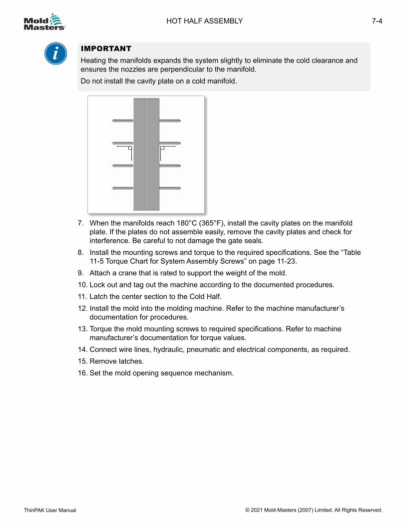
IMPORTANTHeating the manifolds expands the system slightly to eliminate the cold clearance and ensures the nozzles are perpendicular to the manifold.Do not install the cavity plate on a cold manifold.
7. When the manifolds reach 180°C (365°F), install the cavity plates on the manifold plate. If the plates do not assemble easily, remove the cavity plates and check for interference. Be careful to not damage the gate seals.
8. Install the mounting screws and torque to the required specifications. See the “Table 11-5 Torque Chart for System Assembly Screws” on page 11-23.
9. Attach a crane that is rated to support the weight of the mold.10. Lock out and tag out the machine according to the documented procedures.11. Latch the center section to the Cold Half.12. Install the mold into the molding machine. Refer to the machine manufacturer’s
documentation for procedures.13. Torque the mold mounting screws to required specifications. Refer to machine
manufacturer’s documentation for torque values.14. Connect wire lines, hydraulic, pneumatic and electrical components, as required.15. Remove latches.16. Set the mold opening sequence mechanism.
7-4
© 2021 Mold-Masters (2007) Limited. All Rights Reserved.
HOT HALF ASSEMBLY
ThinPAK User Manual
Section 8 - System Startup and ShutdownWARNINGEnsure that you have fully read “Section 3 - Safety” before starting up or shutting down the Hot Runner.
8.1 Pre-StartupWARNING Take appropriate safety precautions by assuming the system is pressurized and hot at all times.
CAUTIONWater must be turned on for Hot Runner actuation before turning on temperature controls. Actuator water temperature cannot exceed 29.4 °C (85°F).When running thermally sensitive materials, use a thermally stable material as recommended by the material supplier for the initial startup.After the Hot Runner system is installed in the molding machine, make sure to bleed all the air out of the hydraulic lines, if applicable. Failure to do so could result in high gate vestige. Check that the system is heated to processing temperature before actuating the valve pins. Failure to do so could cause damage to the valve pins.The maximum operating temperature for Hot Runner systems is 400°C (750°F).
CAUTION
1. Install the mold into the molding machine.
NOTE Ensure that the machine nozzle opening is the same size, or is not more than 1.0 mm (0.040 in.) smaller, than the back plate bore.
2. Connect all water lines and test to ensure there are no leaks and that the required flow is achieved in all water circuits.
3. Connect all hydraulic / pneumatic lines, if applicable.4. Connect all electrical components and monitor to ensure that all zones are receiving
heat and all thermocouples are reacting appropriately.5. If applicable, test the valve pin actuation, but only if the Hot Runner is at processing
temperature. See CAUTION above.
8-1SYSTEM STARTUP AND SHUTDOWN
ThinPAK User Manual © 2021 Mold-Masters (2007) Limited. All Rights Reserved.
8.2 StartupWARNINGWhen the mold is open never inject material through Hot Runner system under high pressure. Failure to do so can result in serious injury or death.
The correct startup procedure for your Hot Runner system depends on the type of system:• Standard systems: see “8.2.1 Standard Hot Runner Systems” on page 8-2• Stack mold systems: see “8.3.2 Stack Mold System” on page 8-4
8.2.1 Standard Hot Runner SystemsCAUTION Failure to follow this procedure may result in leakage / damage occurring in the Hot Runner.
CAUTION
IMPORTANTWhen running thermally sensitive materials, use a thermally stable material as recommended by the material supplier for the initial startup.
1. Turn on the machine barrel and mold cooling system.2. Prior to start up, ensure the:
a) Machine barrel is up to processing temperature.b) Mold cooling is on and at cooling temperature.
3. Heat up all Hot Runner manifolds and / or bridges and inlets (excluding the nozzles) to processing temperature.
4. Begin nozzle heating when the manifolds and / or bridges have come within 50°C of processing temperature.
IMPORTANTWait until ALL heating zones have reached processing temperature for 5 minutes before continuing.For Hot Runner systems using heater plates, allow 10 minutes of soak time after the system reaches processing temperature.
5. Startup the system.a) For empty systems or where there is no material in the gate detail, extrude material
through the Hot Runner system using 34.4 bar (500 PSI) of back pressure. The purpose is to fill the Visco-Seal at low pressure. This prevents any possibility of leakage past the nozzle seal.
b) For systems filled with material, purge intended shot size twice from the barrel prior to bringing the machine barrel forward to the Hot Runner interface.
6. Set injection time and pressure according to part size, gate size and material.
8-2
© 2021 Mold-Masters (2007) Limited. All Rights Reserved.
SYSTEM STARTUP AND SHUTDOWN
ThinPAK User Manual
8.2.2 Stack Mold Systems
CAUTION Failure to follow this procedure may result in leakage / damage occurring in the Hot Runner.
CAUTION
IMPORTANTWhen running thermally sensitive materials, use a thermally stable material as recommended by the material supplier for the initial startup.
1. Heat up all Hot Runner manifolds, submanifolds, bridges, sub-bridges, and inlets (excluding the nozzles) to processing temperature.
2. After manifolds, submanifolds, bridges and sub-bridges reach set point, heat nozzles and spacers to 150°C (300°F).
3. Heat soak for 15 minutes.4. Raise nozzle temperature to set point.5. Heat soak for 20 minutes.
8.3 ShutdownThe correct shutdown procedure for your Hot Runner system depends on the type of system:
• Standard systems: see “8.3.1 Standard Hot Runner Systems” on page 8-3• Stack mold systems: see ““8.3.2 Stack Mold System” on page 8-4
8.3.1 Standard Hot Runner SystemsCAUTION Failure to follow this procedure may result in leakage / damage occurring in the Hot Runner.
CAUTION
IMPORTANTThermally sensitive materials should be purged from the Hot Runner system prior to shutdown using a thermally stable material with a similar processing temperature.
1. Turn off all heat to the system.2. Leave the mold cooling system turned on until the Hot Runner system temperature is
within 55°C (130°F) of the mold temperature.
8-3SYSTEM STARTUP AND SHUTDOWN
ThinPAK User Manual © 2021 Mold-Masters (2007) Limited. All Rights Reserved.

8.3.2 Stack Mold SystemCAUTION Failure to follow this procedure may result in leakage / damage occurring in the Hot Runner.
CAUTION
IMPORTANTThermally sensitive materials should be purged from the Hot Runner system prior to shutdown using a thermally stable material with a similar processing temperature.
1. Shutdown spacers, bridges and sub-bridges.2. Reduce nozzle temperatures to 230°F (110°C).3. Wait 20 minutes.4. Shutdown manifolds, submanifolds, inlets and nozzles.
8-4
© 2021 Mold-Masters (2007) Limited. All Rights Reserved.
SYSTEM STARTUP AND SHUTDOWN
ThinPAK User Manual

Section 9 - Color ChangeWARNINGEnsure that you have fully read “Section 3 - Safety” before purging the Hot Runner system.
Although it is not possible to make a generic color change procedure that will give the best performance in all circumstances because the flow characteristics of the plastic polymers in use can influence color changes, there are specific procedures which work to enhance color changes.
9.1 General Tips• Always process a natural / clear color for the first shot on an empty Hot Runner system
to coat the melt channel walls and gate bubbles with a neutral color.• Ensure the hopper and conveying system are free of all contamination from the
previous production color. Many times the previous color will hang up in the hopper or conveying system and be slowly released into the mold resulting in contaminated parts. Also, make sure there is no contamination in the resin being used in production.
• Schedule color changes from light to progressively darker.• Understand the economics of your color change to decide if it is economically better to
take the time to latch over the cavity plate and clean out the gate bubbles or just run scrap parts slightly longer to clean out the gate bubble area.
• Use purge compounds for color change in the machine barrel and Hot Runner.
9.2 Procedure A: Simple and Effective
WARNING To avoid serious burns when purging, wear safety clothing consisting of a protective heat-resistant coat, heat-resistant gloves and a full face shield over safety glasses.Use adequate ventilation for fumes. Some plastics develop gases that may be dangerous to personal health. Follow the plastics supplier’s recommendations.Do not look directly into the feed throat of a hopper - use a mirror. Unexpected release of resin may cause serious burns.Never handle plastic purgings or drool until they have completely cooled. Purgings may appear solid but may still be hot and cause serious injury.
1. Empty hopper of existing color and clean thoroughly.2. Increase Hot Runner system temperature on all zones 20°C (68°F) above processing
temperatures. On Mold-Masters controllers, simply push the boost button on the controller to increase temperatures for a pre-determined time and temperature.
3. Back off the machine barrel, introduce the appropriate purge compound and purge until previous material is cleaned, then introduce new color. Increase barrel / extruder heats to help flush previous color (see machine maker recommendations).
4. Increase injection speed to help flush previous material.5. Use Hot Runner purging compound (e.g. ASACLEAN™, Dyna-Purge®) at
9-1COLOR CHANGE
ThinPAK User Manual © 2021 Mold-Masters (2007) Limited. All Rights Reserved.
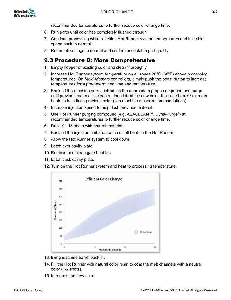
recommended temperatures to further reduce color change time.6. Run parts until color has completely flushed through.7. Continue processing while resetting Hot Runner system temperatures and injection
speed back to normal.8. Return all settings to normal and confirm acceptable part quality.
9.3 Procedure B: More Comprehensive1. Empty hopper of existing color and clean thoroughly.2. Increase Hot Runner system temperature on all zones 20°C (68°F) above processing
temperatures. On Mold-Masters controllers, simply push the boost button to increase temperatures for a pre-determined time and temperature.
3. Back off the machine barrel, introduce the appropriate purge compound and purge until previous material is cleaned, then introduce new color. Increase barrel / extruder heats to help flush previous color (see machine maker recommendations).
4. Increase injection speed to help flush previous material.5. Use Hot Runner purging compound (e.g. ASACLEAN™, Dyna-Purge®) at
recommended temperatures to further reduce color change time.6. Run 10 - 15 shots with natural material.7. Back off the injection unit and switch off all heat on the Hot Runner.8. Allow the Hot Runner system to cool down.9. Latch over cavity plate.10. Remove and clean gate bubbles.11. Latch back cavity plate.12. Turn on the Hot Runner system and heat to processing temperature.
13. Bring machine barrel back in.14. Fill the Hot Runner with natural color resin to coat the melt channels with a neutral
color (1-2 shots).15. Introduce the new color.
9-2
© 2021 Mold-Masters (2007) Limited. All Rights Reserved.
COLOR CHANGE
ThinPAK User Manual

16. Leave mold in open position and set the shot size to maximum possible.17. Purge the entire shot through the Hot Runner and out the gates into the exposed cavity
at the highest injection rate possible. Repeat this several times.
NOTEIt may be advisable to put a protective shield over the core side to prevent plastic from injecting and cooling on the core side.
18. Set the shot size back to normal levels and begin processing parts with increased injection speeds and mold temperature.
19. Continue processing while resetting Hot Runner system temperatures and injection speed back to normal.
20. Return all settings to normal and confirm acceptable part quality.
9-3COLOR CHANGE
ThinPAK User Manual © 2021 Mold-Masters (2007) Limited. All Rights Reserved.
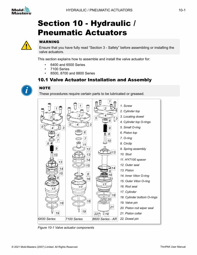
Section 10 - Hydraulic / Pneumatic ActuatorsWARNINGEnsure that you have fully read “Section 3 - Safety” before assembling or installing the valve actuators.
This section explains how to assemble and install the valve actuator for:• 6400 and 6500 Series• 7100 Series• 8500, 8700 and 8800 Series
10.1 Valve Actuator Installation and Assembly
NOTEThese procedures require certain parts to be lubricated or greased.
Figure 10-1 Valve actuator components
1. Screw
2. Cylinder top
3. Locating dowel
4. Cylinder top O-rings
5. Small O-ring
6. Piston top
7. O-ring
8. Circlip
9. Spring assembly
10. Stud
11. HY7100 spacer
12. Outer seal
13. Piston
14. Inner Viton O-ring
15. Outer Viton O-ring
16. Rod seal
17. Cylinder
18. Cylinder bottom O-rings
19. Valve pin
20. Piston rod wiper seal
21. Piston collar
22. Dowel pin6X00 Series 7100 Series 8600 Series - AR
11
22
334
455
66
778
9
10
1112
13
13
14
88
14
15
15
1616
17 17
18 18
19 1919
20
21
22
1
2
34
56
8
9
10
13
14816
17
18
10-1HYDRAULIC / PNEUMATIC ACTUATORS
ThinPAK User Manual © 2021 Mold-Masters (2007) Limited. All Rights Reserved.
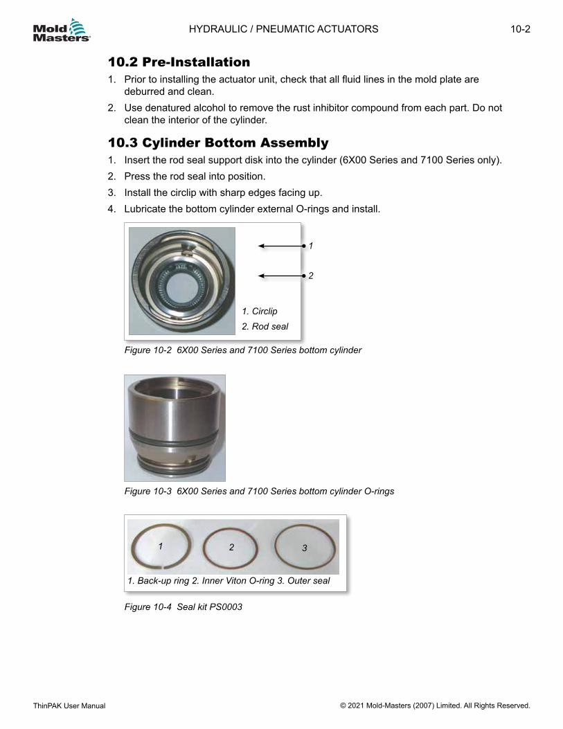
10.2 Pre-Installation1. Prior to installing the actuator unit, check that all fluid lines in the mold plate are
deburred and clean.2. Use denatured alcohol to remove the rust inhibitor compound from each part. Do not
clean the interior of the cylinder.
10.3 Cylinder Bottom Assembly1. Insert the rod seal support disk into the cylinder (6X00 Series and 7100 Series only).2. Press the rod seal into position.3. Install the circlip with sharp edges facing up.4. Lubricate the bottom cylinder external O-rings and install.
1. Circlip2. Rod seal
Figure 10-2 6X00 Series and 7100 Series bottom cylinder
Figure 10-3 6X00 Series and 7100 Series bottom cylinder O-rings
1. Back-up ring 2. Inner Viton O-ring 3. Outer seal
1 2 3
Figure 10-4 Seal kit PS0003
1
2
10-2
© 2021 Mold-Masters (2007) Limited. All Rights Reserved.
HYDRAULIC / PNEUMATIC ACTUATORS
ThinPAK User Manual
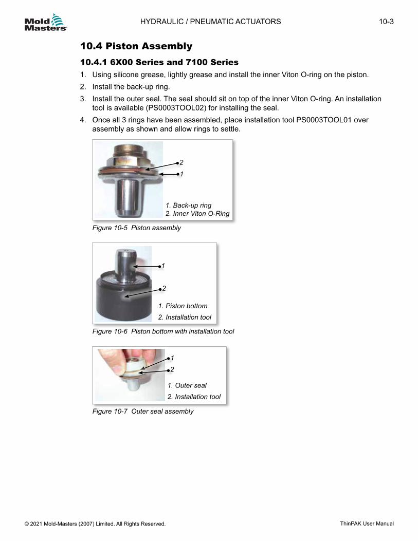
10.4 Piston Assembly10.4.1 6X00 Series and 7100 Series1. Using silicone grease, lightly grease and install the inner Viton O-ring on the piston.2. Install the back-up ring.3. Install the outer seal. The seal should sit on top of the inner Viton O-ring. An installation
tool is available (PS0003TOOL02) for installing the seal.4. Once all 3 rings have been assembled, place installation tool PS0003TOOL01 over
assembly as shown and allow rings to settle.
1. Back-up ring 2. Inner Viton O-Ring
2
1
Figure 10-5 Piston assembly
1. Piston bottom2. Installation tool
1
2
Figure 10-6 Piston bottom with installation tool
1. Outer seal2. Installation tool
2
1
Figure 10-7 Outer seal assembly
10-3HYDRAULIC / PNEUMATIC ACTUATORS
ThinPAK User Manual © 2021 Mold-Masters (2007) Limited. All Rights Reserved.
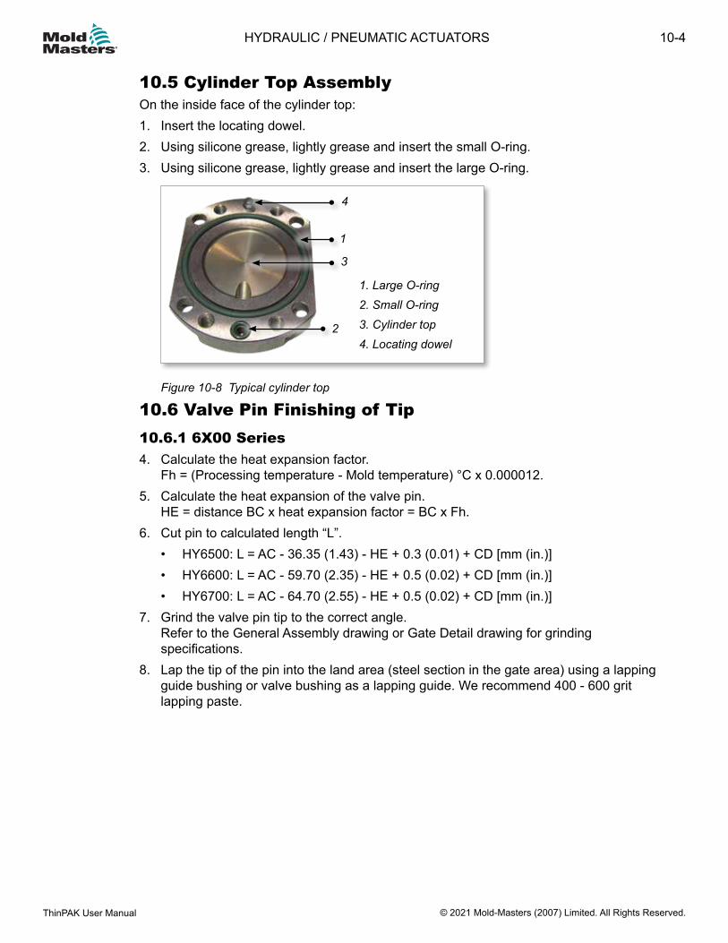
10.5 Cylinder Top AssemblyOn the inside face of the cylinder top:1. Insert the locating dowel.2. Using silicone grease, lightly grease and insert the small O-ring.3. Using silicone grease, lightly grease and insert the large O-ring.
44
1. Large O-ring2. Small O-ring3. Cylinder top4. Locating dowel
4
1
3
2
Figure 10-8 Typical cylinder top
10.6 Valve Pin Finishing of Tip10.6.1 6X00 Series4. Calculate the heat expansion factor.
Fh = (Processing temperature - Mold temperature) °C x 0.000012.5. Calculate the heat expansion of the valve pin.
HE = distance BC x heat expansion factor = BC x Fh.6. Cut pin to calculated length “L”.
• HY6500: L = AC - 36.35 (1.43) - HE + 0.3 (0.01) + CD [mm (in.)]• HY6600: L = AC - 59.70 (2.35) - HE + 0.5 (0.02) + CD [mm (in.)]• HY6700: L = AC - 64.70 (2.55) - HE + 0.5 (0.02) + CD [mm (in.)]
7. Grind the valve pin tip to the correct angle. Refer to the General Assembly drawing or Gate Detail drawing for grinding specifications.
8. Lap the tip of the pin into the land area (steel section in the gate area) using a lapping guide bushing or valve bushing as a lapping guide. We recommend 400 - 600 grit lapping paste.
10-4
© 2021 Mold-Masters (2007) Limited. All Rights Reserved.
HYDRAULIC / PNEUMATIC ACTUATORS
ThinPAK User Manual
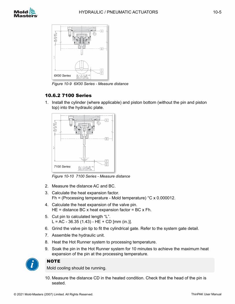
6X00 Series
Figure 10-9 6X00 Series - Measure distance
10.6.2 7100 Series1. Install the cylinder (where applicable) and piston bottom (without the pin and piston
top) into the hydraulic plate.
7100 Series
Figure 10-10 7100 Series - Measure distance
2. Measure the distance AC and BC.3. Calculate the heat expansion factor.
Fh = (Processing temperature - Mold temperature) °C x 0.000012.4. Calculate the heat expansion of the valve pin.
HE = distance BC x heat expansion factor = BC x Fh.5. Cut pin to calculated length “L”.
L = AC - 36.35 (1.43) - HE + CD [mm (in.)].6. Grind the valve pin tip to fit the cylindrical gate. Refer to the system gate detail.7. Assemble the hydraulic unit.8. Heat the Hot Runner system to processing temperature.9. Soak the pin in the Hot Runner system for 10 minutes to achieve the maximum heat
expansion of the pin at the processing temperature.
NOTEMold cooling should be running.
10. Measure the distance CD in the heated condition. Check that the head of the pin is seated.
10-5HYDRAULIC / PNEUMATIC ACTUATORS
ThinPAK User Manual © 2021 Mold-Masters (2007) Limited. All Rights Reserved.

11. Calculate the dimension to be ground (L2). L2 = CD (measurement) - CD (specified).12. Grind the pin end to remove L2 (finish cut).
NOTEWhen the gate vestige is critical, it is recommended to mold sample parts and measure samples to adjust the final pin length.
Steel quality in the gating area must have:• Tapered gates - High grade of toughness (H13, 1.2344), hardness HRc 46-48• Cylindrical gates - Minimum hardness HRc 54• No nitration• No chrome plating
The bottom of the nozzle well in the gate area must be free of stress caused by:• Rough EDM• Rough machining• Sharp corners (JIG grinding is recommended)
10-6
© 2021 Mold-Masters (2007) Limited. All Rights Reserved.
HYDRAULIC / PNEUMATIC ACTUATORS
ThinPAK User Manual
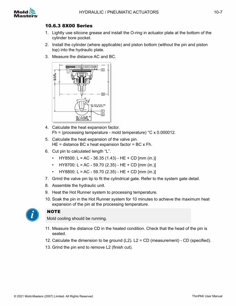
10.6.3 8X00 Series1. Lightly use silicone grease and install the O-ring in actuator plate at the bottom of the
cylinder bore pocket.2. Install the cylinder (where applicable) and piston bottom (without the pin and piston
top) into the hydraulic plate.3. Measure the distance AC and BC.
4. Calculate the heat expansion factor. Fh = (processing temperature - mold temperature) °C x 0.000012.
5. Calculate the heat expansion of the valve pin. HE = distance BC x heat expansion factor = BC x Fh.
6. Cut pin to calculated length “L”.• HY8500: L = AC - 36.35 (1.43) - HE + CD [mm (in.)]• HY8700: L = AC - 59.70 (2.35) - HE + CD [mm (in.)]• HY8800: L = AC - 59.70 (2.35) - HE + CD [mm (in.)]
7. Grind the valve pin tip to fit the cylindrical gate. Refer to the system gate detail.8. Assemble the hydraulic unit.9. Heat the Hot Runner system to processing temperature.10. Soak the pin in the Hot Runner system for 10 minutes to achieve the maximum heat
expansion of the pin at the processing temperature.
NOTEMold cooling should be running.
11. Measure the distance CD in the heated condition. Check that the head of the pin is
seated.12. Calculate the dimension to be ground (L2). L2 = CD (measurement) - CD (specified).13. Grind the pin end to remove L2 (finish cut).
10-7HYDRAULIC / PNEUMATIC ACTUATORS
ThinPAK User Manual © 2021 Mold-Masters (2007) Limited. All Rights Reserved.
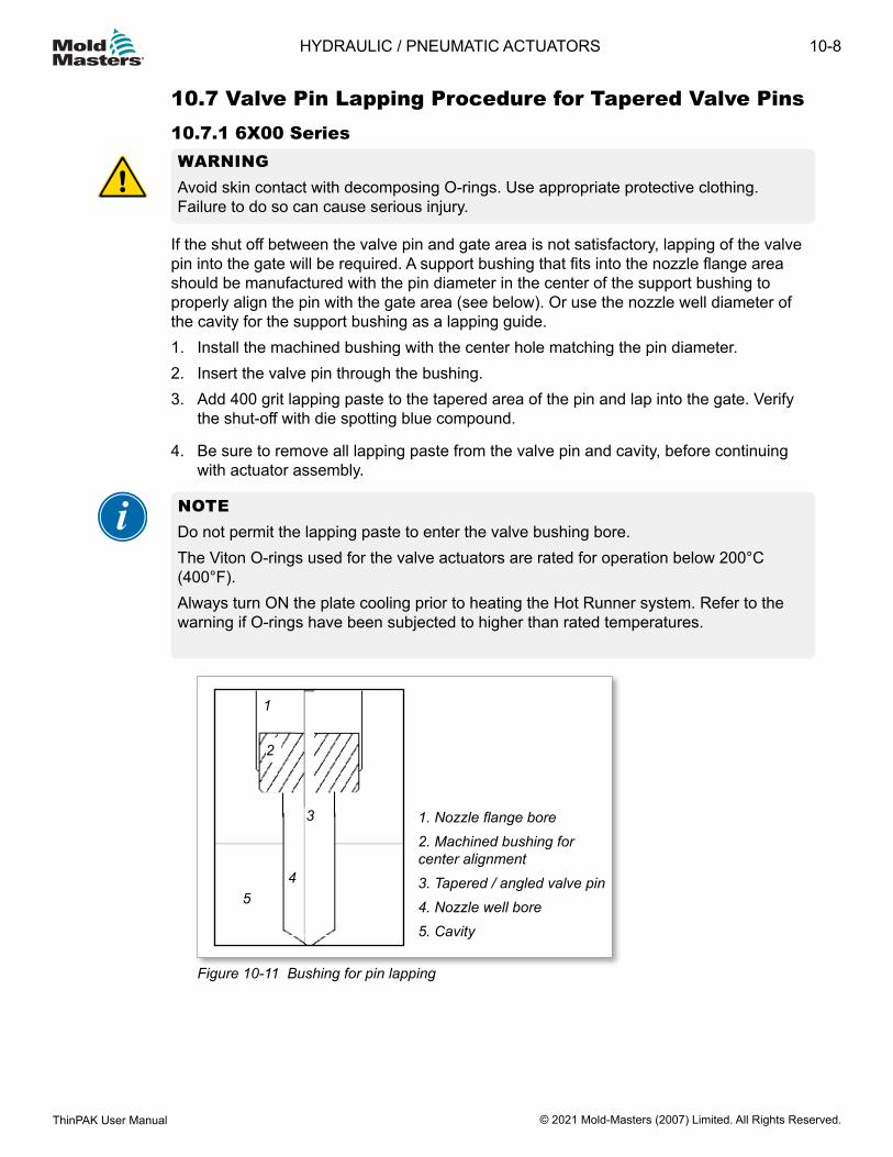
10.7 Valve Pin Lapping Procedure for Tapered Valve Pins10.7.1 6X00 SeriesWARNING Avoid skin contact with decomposing O-rings. Use appropriate protective clothing. Failure to do so can cause serious injury.
If the shut off between the valve pin and gate area is not satisfactory, lapping of the valve pin into the gate will be required. A support bushing that fits into the nozzle flange area should be manufactured with the pin diameter in the center of the support bushing to properly align the pin with the gate area (see below). Or use the nozzle well diameter of the cavity for the support bushing as a lapping guide.1. Install the machined bushing with the center hole matching the pin diameter.2. Insert the valve pin through the bushing.3. Add 400 grit lapping paste to the tapered area of the pin and lap into the gate. Verify
the shut-off with die spotting blue compound.
4. Be sure to remove all lapping paste from the valve pin and cavity, before continuing with actuator assembly.
NOTEDo not permit the lapping paste to enter the valve bushing bore.The Viton O-rings used for the valve actuators are rated for operation below 200°C (400°F). Always turn ON the plate cooling prior to heating the Hot Runner system. Refer to the warning if O-rings have been subjected to higher than rated temperatures.
1. Nozzle flange bore2. Machined bushing for center alignment3. Tapered / angled valve pin 4. Nozzle well bore5. Cavity
1
2
3
45
Figure 10-11 Bushing for pin lapping
10-8
© 2021 Mold-Masters (2007) Limited. All Rights Reserved.
HYDRAULIC / PNEUMATIC ACTUATORS
ThinPAK User Manual
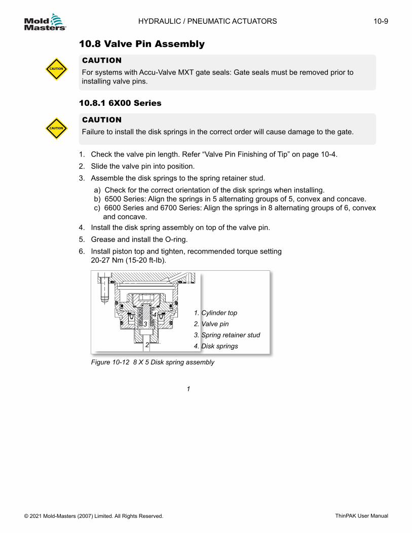
10.8 Valve Pin AssemblyCAUTION For systems with Accu-Valve MXT gate seals: Gate seals must be removed prior to installing valve pins.
CAUTION
10.8.1 6X00 Series
CAUTIONFailure to install the disk springs in the correct order will cause damage to the gate.CAUTION
1. Check the valve pin length. Refer “Valve Pin Finishing of Tip” on page 10-4.2. Slide the valve pin into position.3. Assemble the disk springs to the spring retainer stud.
a) Check for the correct orientation of the disk springs when installing.b) 6500 Series: Align the springs in 5 alternating groups of 5, convex and concave.c) 6600 Series and 6700 Series: Align the springs in 8 alternating groups of 6, convex
and concave.4. Install the disk spring assembly on top of the valve pin.5. Grease and install the O-ring.6. Install piston top and tighten, recommended torque setting
20-27 Nm (15-20 ft-Ib).
1. Cylinder top2. Valve pin3. Spring retainer stud4. Disk springs
3
2
4
Figure 10-12 8 X 5 Disk spring assembly
1
10-9HYDRAULIC / PNEUMATIC ACTUATORS
ThinPAK User Manual © 2021 Mold-Masters (2007) Limited. All Rights Reserved.
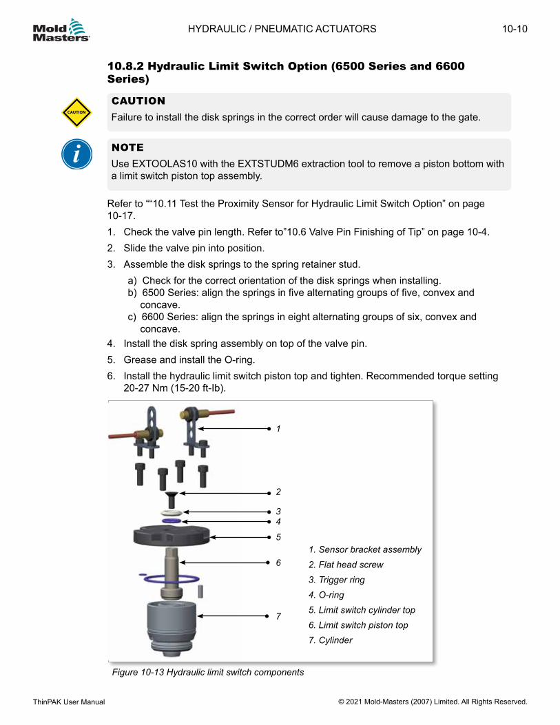
10.8.2 Hydraulic Limit Switch Option (6500 Series and 6600 Series)
CAUTIONFailure to install the disk springs in the correct order will cause damage to the gate.CAUTION
NOTEUse EXTOOLAS10 with the EXTSTUDM6 extraction tool to remove a piston bottom with a limit switch piston top assembly.
Refer to ““10.11 Test the Proximity Sensor for Hydraulic Limit Switch Option” on page 10-17.1. Check the valve pin length. Refer to”10.6 Valve Pin Finishing of Tip” on page 10-4.2. Slide the valve pin into position.3. Assemble the disk springs to the spring retainer stud.
a) Check for the correct orientation of the disk springs when installing.b) 6500 Series: align the springs in five alternating groups of five, convex and
concave.c) 6600 Series: align the springs in eight alternating groups of six, convex and
concave.4. Install the disk spring assembly on top of the valve pin.5. Grease and install the O-ring.6. Install the hydraulic limit switch piston top and tighten. Recommended torque setting
20-27 Nm (15-20 ft-Ib).
Figure 10-13 Hydraulic limit switch components
1
2
34
5
6
7
1. Sensor bracket assembly2. Flat head screw3. Trigger ring4. O-ring5. Limit switch cylinder top6. Limit switch piston top7. Cylinder
10-10
© 2021 Mold-Masters (2007) Limited. All Rights Reserved.
HYDRAULIC / PNEUMATIC ACTUATORS
ThinPAK User Manual
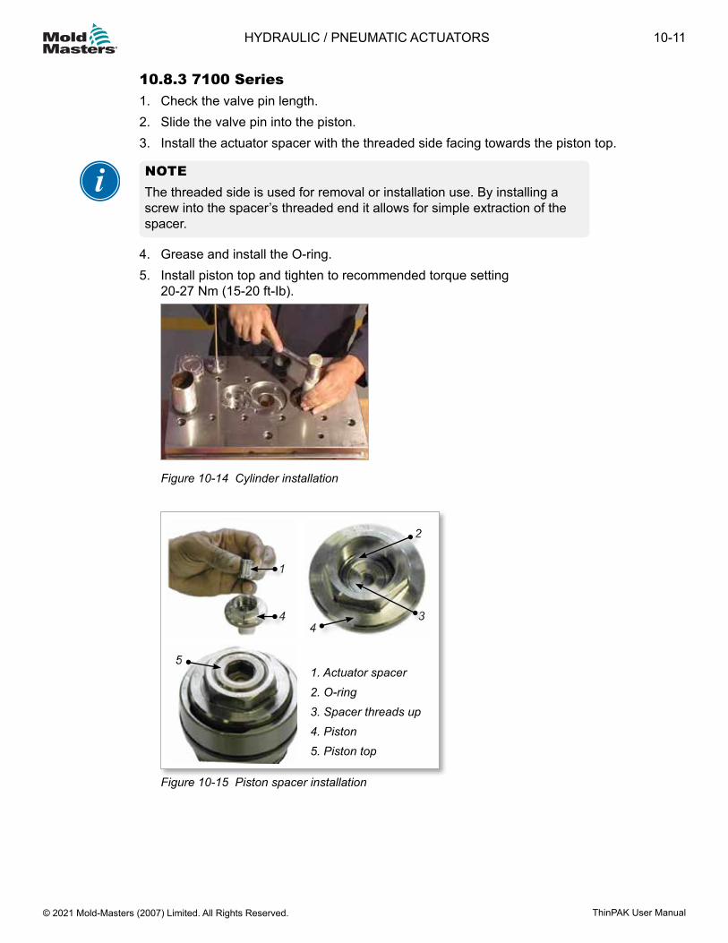
10.8.3 7100 Series1. Check the valve pin length.2. Slide the valve pin into the piston.3. Install the actuator spacer with the threaded side facing towards the piston top.
NOTE The threaded side is used for removal or installation use. By installing a screw into the spacer’s threaded end it allows for simple extraction of the spacer.
4. Grease and install the O-ring.5. Install piston top and tighten to recommended torque setting
20-27 Nm (15-20 ft-Ib).
Figure 10-14 Cylinder installation
1. Actuator spacer2. O-ring3. Spacer threads up4. Piston5. Piston top
1
4
2
34
5
Figure 10-15 Piston spacer installation
10-11HYDRAULIC / PNEUMATIC ACTUATORS
ThinPAK User Manual © 2021 Mold-Masters (2007) Limited. All Rights Reserved.
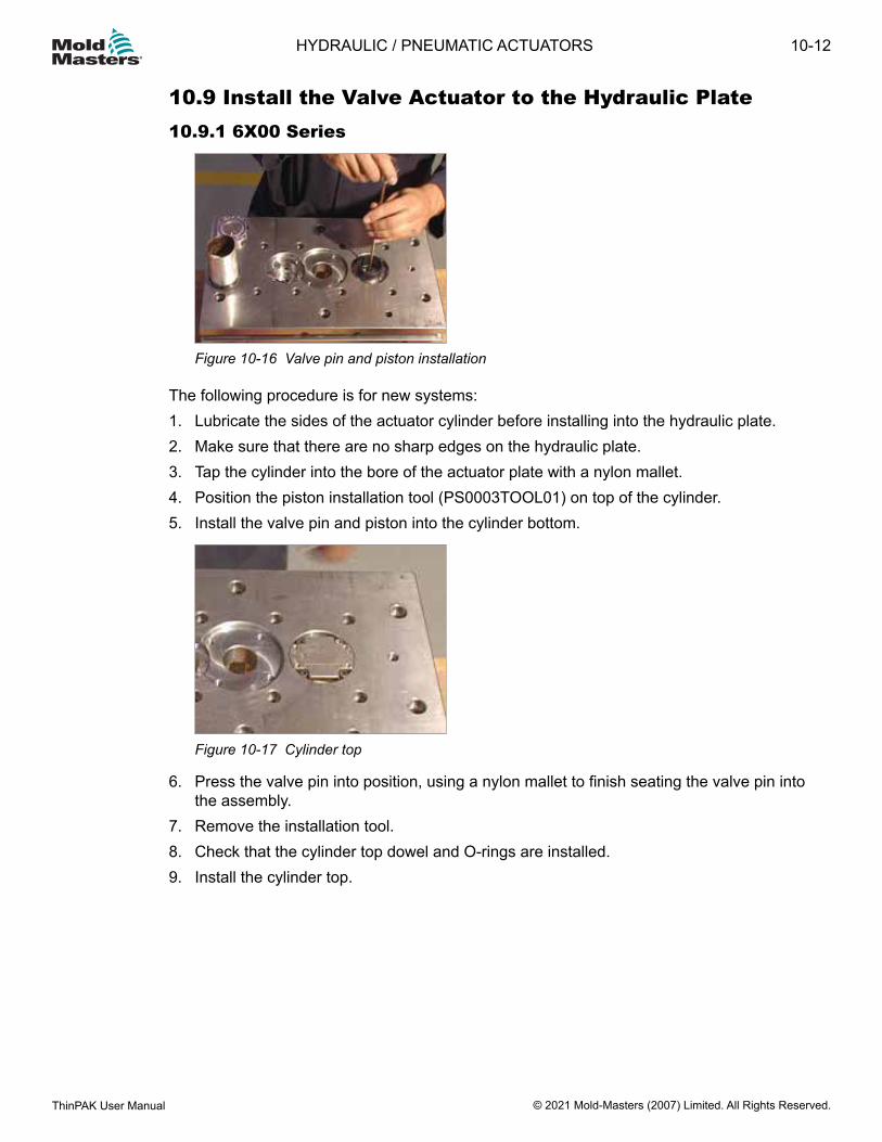
10.9 Install the Valve Actuator to the Hydraulic Plate10.9.1 6X00 Series
Figure 10-16 Valve pin and piston installation
The following procedure is for new systems:1. Lubricate the sides of the actuator cylinder before installing into the hydraulic plate.2. Make sure that there are no sharp edges on the hydraulic plate.3. Tap the cylinder into the bore of the actuator plate with a nylon mallet.4. Position the piston installation tool (PS0003TOOL01) on top of the cylinder.5. Install the valve pin and piston into the cylinder bottom.
Figure 10-17 Cylinder top
6. Press the valve pin into position, using a nylon mallet to finish seating the valve pin into the assembly.
7. Remove the installation tool.8. Check that the cylinder top dowel and O-rings are installed.9. Install the cylinder top.
10-12
© 2021 Mold-Masters (2007) Limited. All Rights Reserved.
HYDRAULIC / PNEUMATIC ACTUATORS
ThinPAK User Manual
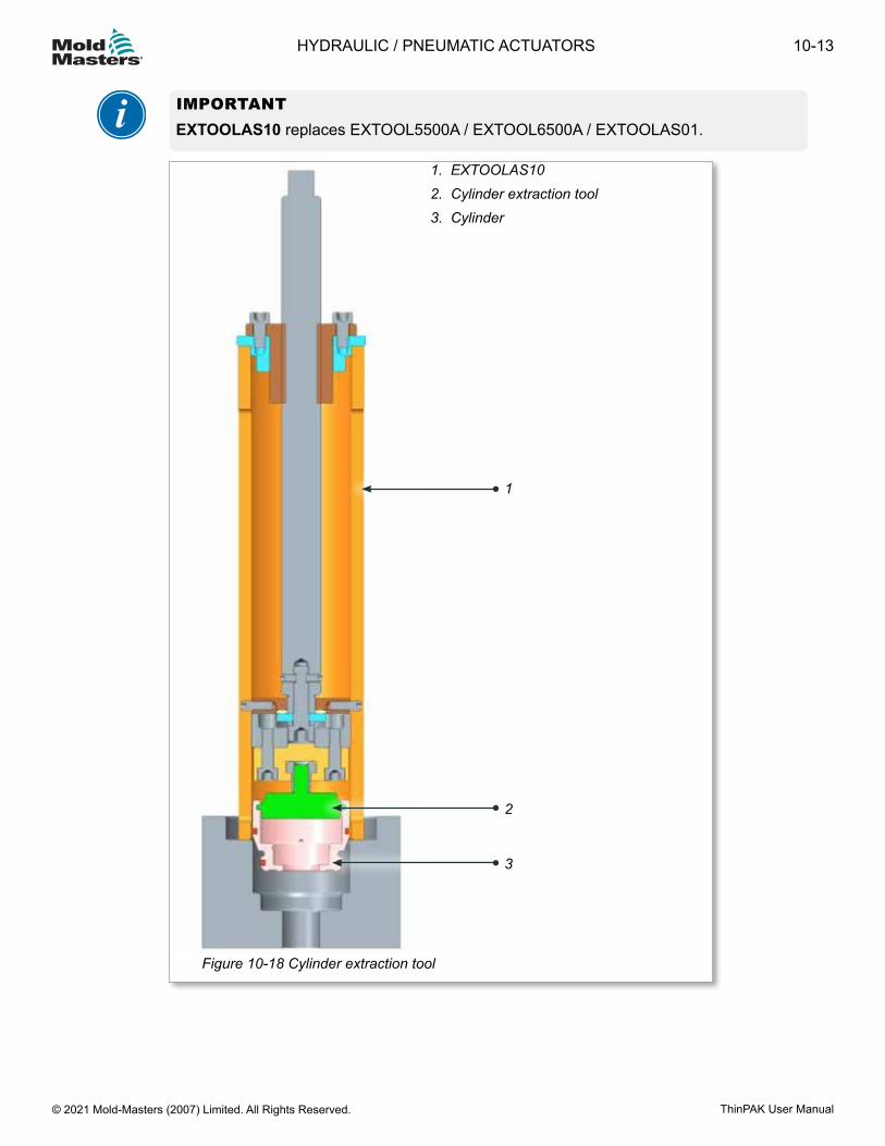
IMPORTANTEXTOOLAS10 replaces EXTOOL5500A / EXTOOL6500A / EXTOOLAS01.
1. EXTOOLAS102. Cylinder extraction tool3. Cylinder
1
3
2
Figure 10-18 Cylinder extraction tool
10-13HYDRAULIC / PNEUMATIC ACTUATORS
ThinPAK User Manual © 2021 Mold-Masters (2007) Limited. All Rights Reserved.
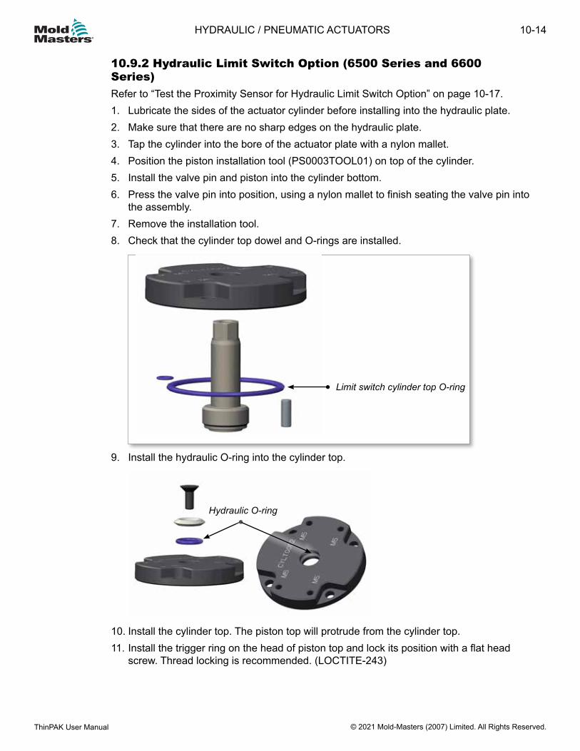
10.9.2 Hydraulic Limit Switch Option (6500 Series and 6600 Series)Refer to “Test the Proximity Sensor for Hydraulic Limit Switch Option” on page 10-17.1. Lubricate the sides of the actuator cylinder before installing into the hydraulic plate.2. Make sure that there are no sharp edges on the hydraulic plate.3. Tap the cylinder into the bore of the actuator plate with a nylon mallet.4. Position the piston installation tool (PS0003TOOL01) on top of the cylinder.5. Install the valve pin and piston into the cylinder bottom.6. Press the valve pin into position, using a nylon mallet to finish seating the valve pin into
the assembly.7. Remove the installation tool.8. Check that the cylinder top dowel and O-rings are installed.
9. Install the hydraulic O-ring into the cylinder top.
Hydraulic O-ring
10. Install the cylinder top. The piston top will protrude from the cylinder top.11. Install the trigger ring on the head of piston top and lock its position with a flat head
screw. Thread locking is recommended. (LOCTITE-243)
Limit switch cylinder top O-ring
10-14
© 2021 Mold-Masters (2007) Limited. All Rights Reserved.
HYDRAULIC / PNEUMATIC ACTUATORS
ThinPAK User Manual
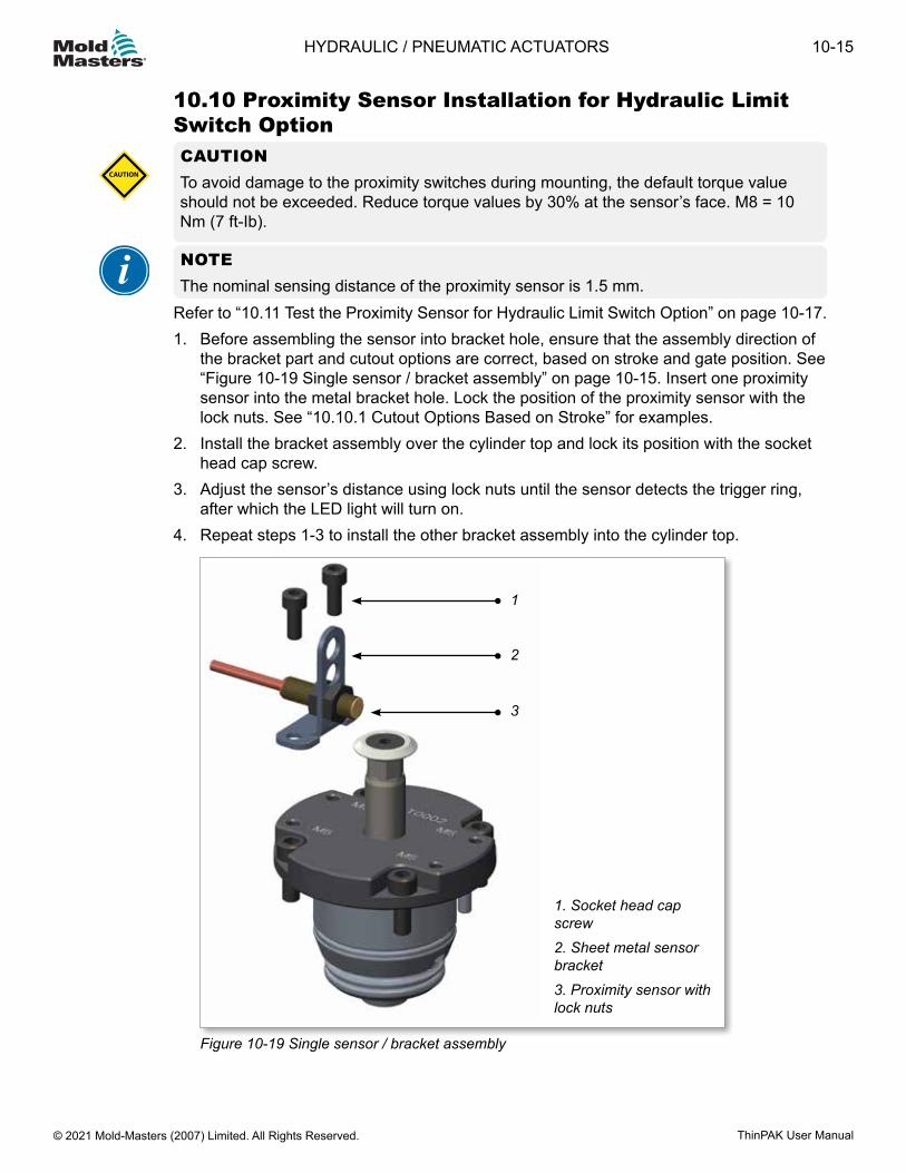
10.10 Proximity Sensor Installation for Hydraulic Limit Switch OptionCAUTIONTo avoid damage to the proximity switches during mounting, the default torque value should not be exceeded. Reduce torque values by 30% at the sensor’s face. M8 = 10 Nm (7 ft-Ib).
CAUTION
NOTEThe nominal sensing distance of the proximity sensor is 1.5 mm.
Refer to “10.11 Test the Proximity Sensor for Hydraulic Limit Switch Option” on page 10-17.1. Before assembling the sensor into bracket hole, ensure that the assembly direction of
the bracket part and cutout options are correct, based on stroke and gate position. See “Figure 10-19 Single sensor / bracket assembly” on page 10-15. Insert one proximity sensor into the metal bracket hole. Lock the position of the proximity sensor with the lock nuts. See “10.10.1 Cutout Options Based on Stroke” for examples.
2. Install the bracket assembly over the cylinder top and lock its position with the socket head cap screw.
3. Adjust the sensor’s distance using lock nuts until the sensor detects the trigger ring, after which the LED light will turn on.
4. Repeat steps 1-3 to install the other bracket assembly into the cylinder top.
1. Socket head cap screw2. Sheet metal sensor bracket3. Proximity sensor with lock nuts
2
1
3
Figure 10-19 Single sensor / bracket assembly
10-15HYDRAULIC / PNEUMATIC ACTUATORS
ThinPAK User Manual © 2021 Mold-Masters (2007) Limited. All Rights Reserved.
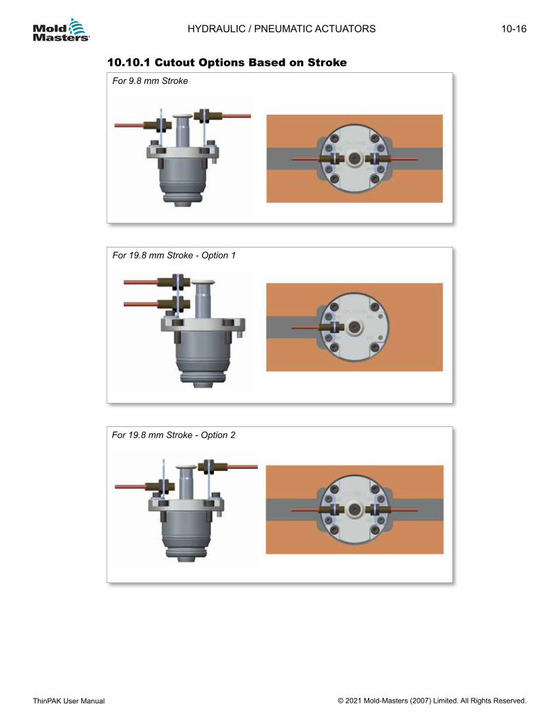
10.10.1 Cutout Options Based on StrokeFor 9.8 mm Stroke
For 19.8 mm Stroke - Option 1
For 19.8 mm Stroke - Option 2
10-16
© 2021 Mold-Masters (2007) Limited. All Rights Reserved.
HYDRAULIC / PNEUMATIC ACTUATORS
ThinPAK User Manual

10.11 Test the Proximity Sensor for Hydraulic Limit Switch OptionWARNING Use the appropriate protective clothing when you work with moving parts. Failure to do so can cause serious injury.
CAUTION Voltage supply to proximity sensor shall be <30 VDC and the output current shall be <200 mA. Excess voltage and current could damage the sensors.Make sure that the proximity sensor cables are free from mechanical devices which could damage them.
CAUTION
NOTEThe operating temperature of the proximity sensors is from -25 to 180°C (-13 to 356°F).
1. Make sure that the hydraulic system is completely assembled.2. Apply a voltage of 10 to 30 VDC to the proximity sensor. Make sure it is <30 VDC.3. Operate the hydraulic actuator until the piston is in the closed position. Stop the
hydraulic actuator at this position.4. Adjust the sensor’s distance using the lock nuts until the sensor detects the trigger
ring, after which the LED light will turn on.5. Operate the hydraulic actuator until the piston top is in the open position. Stop the
hydraulic actuator at this position.6. Adjust the second proximity sensor’s distance using the lock nuts until the sensor
detects the trigger ring, after which the LED light will turn on.7. Disconnect the proximity sensor and the hydraulic actuator unit from the power supply.8. If applicable, install the sensor plate with the screws as per the specification on the
General Assembly drawing.
10.12 Maintenance Procedures for 5500 Series, 6X00 Series and 7100 SeriesWARNING Extreme heat. Avoid contact with heated surfaces.Use appropriate protective clothing. Failure to do so can cause serious injury. If possible keep cooling on within Hot Half. Do not assemble new O-rings if the plates are still hot. Drain the oil before removing the pin from the hydraulics.
10-17HYDRAULIC / PNEUMATIC ACTUATORS
ThinPAK User Manual © 2021 Mold-Masters (2007) Limited. All Rights Reserved.
CAUTIONHeat sensitive materials should be purged from the system prior to maintenance. Failure to do so may result in degradation of material in the system.When heating the Hot Runner system for maintenance, mold cooling should be on to protect seals and O-rings.For systems with Accu-Valve gate seals:Gate seals must be removed prior to removing or re-installing valve pins.If material is present in the mold, raise nozzle temperature enough to allow removal or installation of the valve pin. However, nozzle temperature should not be high enough to allow excessive material flow from the nozzle into the thread area.After installing valve pins thoroughly clean the nozzle seat and thread area.Actuator units should be inspected every 12 months or according to the pre-determined maintenance schedule.
CAUTION
The following procedures are performed on a bench.
10.12.1 For Oil Systems:1. Remove oil from system.2. Remove the cylinder top with tool in upright position to prevent oil from entering the
system.3. Heat up the system (required to remove the valve pin).
10.12.2 For Pneumatic Systems:1. Remove the cylinder top for every zone.2. Heat up the system (required to remove the valve pin).3. Install the cylinder extraction tool to assist with the removal of the cylinder. 4. Disassemble the system.5. Inspect components.6. Replace O-rings. O-ring replacement kit is OR550P1 for 5500 Series and OR650P2 for
6X00 Series and 7100 Series.7. When installing the rod seal, check that the rod seal is seated to the base of the
cylinder and is secured in place with the circlip.8. To complete the assembly, refer to:
a) Cylinder bottom assemblyb) Piston assemblyc) Cylinder top assemblyd) Figure valve pin assemblye) Installing the valve actuator to the hydraulic plate
10-18
© 2021 Mold-Masters (2007) Limited. All Rights Reserved.
HYDRAULIC / PNEUMATIC ACTUATORS
ThinPAK User Manual
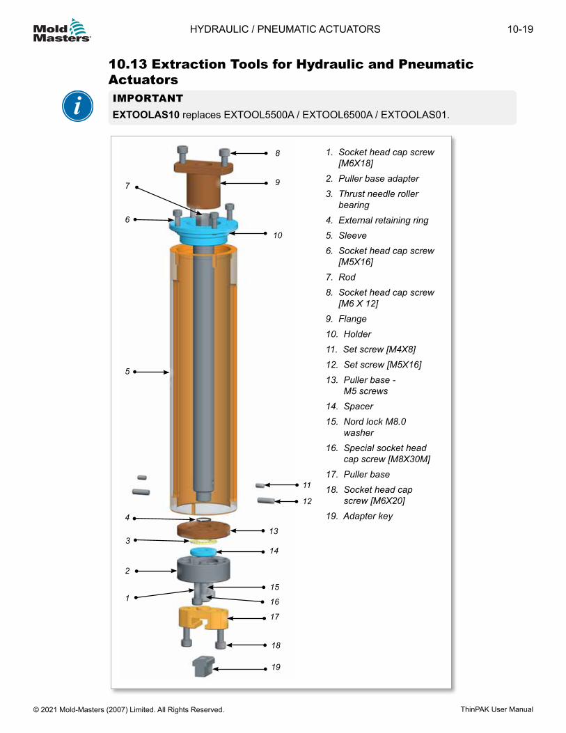
1
2
3
4
5
6
7
8
9
10
11
12
13
14
15
16
17
18
19
10.13 Extraction Tools for Hydraulic and Pneumatic ActuatorsIMPORTANTEXTOOLAS10 replaces EXTOOL5500A / EXTOOL6500A / EXTOOLAS01.
1. Socket head cap screw [M6X18]2. Puller base adapter3. Thrust needle roller bearing4. External retaining ring5. Sleeve6. Socket head cap screw [M5X16]7. Rod8. Socket head cap screw [M6 X 12]9. Flange10. Holder11. Set screw [M4X8]12. Set screw [M5X16]13. Puller base - M5 screws14. Spacer15. Nord lock M8.0 washer16. Special socket head cap screw [M8X30M]17. Puller base18. Socket head cap screw [M6X20]19. Adapter key
10-19HYDRAULIC / PNEUMATIC ACTUATORS
ThinPAK User Manual © 2021 Mold-Masters (2007) Limited. All Rights Reserved.
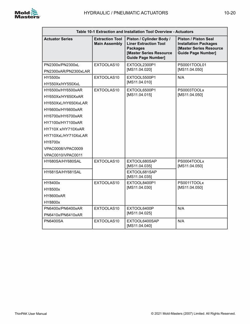
Table 10-1 Extraction and Installation Tool Overview - Actuators
Actuator Series Extraction Tool Main Assembly
Piston / Cylinder Body / Liner Extraction Tool Packages [Master Series Resource Guide Page Number]
Piston / Piston Seal Installation Packages [Master Series Resource Guide Page Number]
PN2300x/PN2300xLPN2300xAR/PN2300xLAR
EXTOOLAS10 EXTOOL2300P1 [MS11.04.020]
PS0001TOOL01 [MS11.04.050]
HY5500xHY550Xx/HY550XxL
EXTOOLAS10 EXTOOL5500P1 [MS11.04.010]
N/A
HY6500x/HY6500xARHY650Xx/HY650XxARHY650XxL/HY650XxLARHY6600x/HY6600xARHY6700x/HY6700xARHY7100x/HY7100xARHY710X x/HY710XxARHY710XxL/HY710XxLARHY8700xVPAC0008/VPAC0009VPAC0010/VPAC0011
EXTOOLAS10 EXTOOL6500P1 [MS11.04.015]
PS0003TOOLx [MS11.04.050]
HY680SA/HY680SAL EXTOOLAS10 EXTOOL680SAP [MS11.04.035]
PS0004TOOLx [MS11.04.050]
HY681SA/HY681SAL EXTOOL681SAP [MS11.04.035]
HY8400xHY8500xHY8600xARHY8800x
EXTOOLAS10 EXTOOL8400P1 [MS11.04.030]
PS0011TOOLx [MS11.04.050]
PN6400x/PN6400xARPN6410x/PN6410xAR
EXTOOLAS10 EXTOOL6400P [MS11.04.025]
N/A
PN6400SA EXTOOLAS10 EXTOOL6400SAP [MS11.04.040]
N/A
10-20
© 2021 Mold-Masters (2007) Limited. All Rights Reserved.
HYDRAULIC / PNEUMATIC ACTUATORS
ThinPAK User Manual
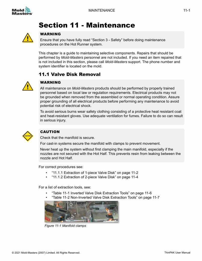
Section 11 - MaintenanceWARNINGEnsure that you have fully read “Section 3 - Safety” before doing maintenance procedures on the Hot Runner system.
This chapter is a guide to maintaining selective components. Repairs that should be performed by Mold-Masters personnel are not included. If you need an item repaired that is not included in this section, please call Mold-Masters support. The phone number and system identifier is located on the mold.
11.1 Valve Disk RemovalWARNINGAll maintenance on Mold-Masters products should be performed by properly trained personnel based on local law or regulation requirements. Electrical products may not be grounded when removed from the assembled or normal operating condition. Assure proper grounding of all electrical products before performing any maintenance to avoid potential risk of electrical shock.To avoid serious burns wear safety clothing consisting of a protective heat resistant coat and heat-resistant gloves. Use adequate ventilation for fumes. Failure to do so can result in serious injury.
CAUTIONCheck that the manifold is secure. For cast-in systems secure the manifold with clamps to prevent movement. Never heat up the system without first clamping the main manifold, especially if the nozzles are not secured with the Hot Half. This prevents resin from leaking between the nozzle and Hot Half.
CAUTION
For correct procedures see:• “11.1.1 Extraction of 1-piece Valve Disk” on page 11-2• “11.1.2 Extraction of 2-piece Valve Disk” on page 11-4
For a list of extraction tools, see:• “Table 11-1 Inverted Valve Disk Extraction Tools” on page 11-6 • “Table 11-2 Non-Inverted Valve Disk Extraction Tools” on page 11-7
Figure 11-1 Manifold clamps
11-1MAINTENANCE
ThinPAK User Manual © 2021 Mold-Masters (2007) Limited. All Rights Reserved.
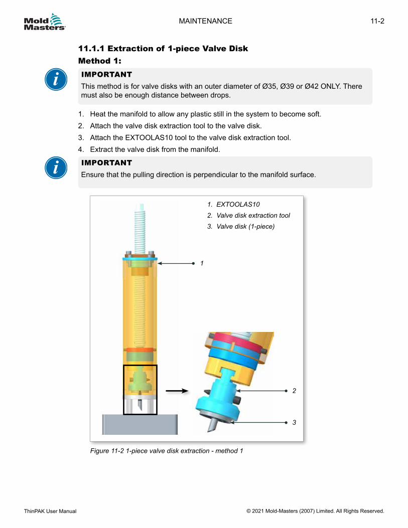
11.1.1 Extraction of 1-piece Valve DiskMethod 1:IMPORTANTThis method is for valve disks with an outer diameter of Ø35, Ø39 or Ø42 ONLY. There must also be enough distance between drops.
1. Heat the manifold to allow any plastic still in the system to become soft.2. Attach the valve disk extraction tool to the valve disk.3. Attach the EXTOOLAS10 tool to the valve disk extraction tool.4. Extract the valve disk from the manifold.
IMPORTANTEnsure that the pulling direction is perpendicular to the manifold surface.
1. EXTOOLAS102. Valve disk extraction tool3. Valve disk (1-piece)
1
3
2
Figure 11-2 1-piece valve disk extraction - method 1
11-2
© 2021 Mold-Masters (2007) Limited. All Rights Reserved.
MAINTENANCE
ThinPAK User Manual
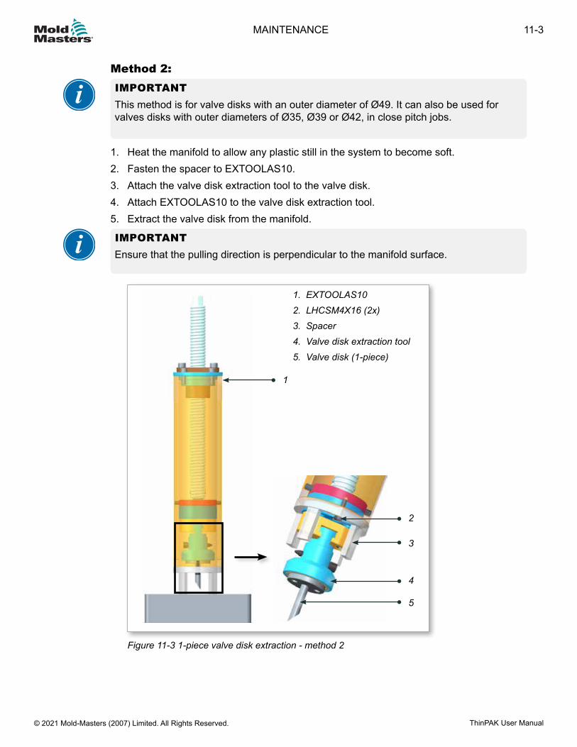
Method 2:IMPORTANTThis method is for valve disks with an outer diameter of Ø49. It can also be used for valves disks with outer diameters of Ø35, Ø39 or Ø42, in close pitch jobs.
1. Heat the manifold to allow any plastic still in the system to become soft.2. Fasten the spacer to EXTOOLAS10.3. Attach the valve disk extraction tool to the valve disk.4. Attach EXTOOLAS10 to the valve disk extraction tool.5. Extract the valve disk from the manifold.
IMPORTANTEnsure that the pulling direction is perpendicular to the manifold surface.
1. EXTOOLAS102. LHCSM4X16 (2x)3. Spacer4. Valve disk extraction tool5. Valve disk (1-piece)
1
Figure 11-3 1-piece valve disk extraction - method 2
3
4
2
5
11-3MAINTENANCE
ThinPAK User Manual © 2021 Mold-Masters (2007) Limited. All Rights Reserved.
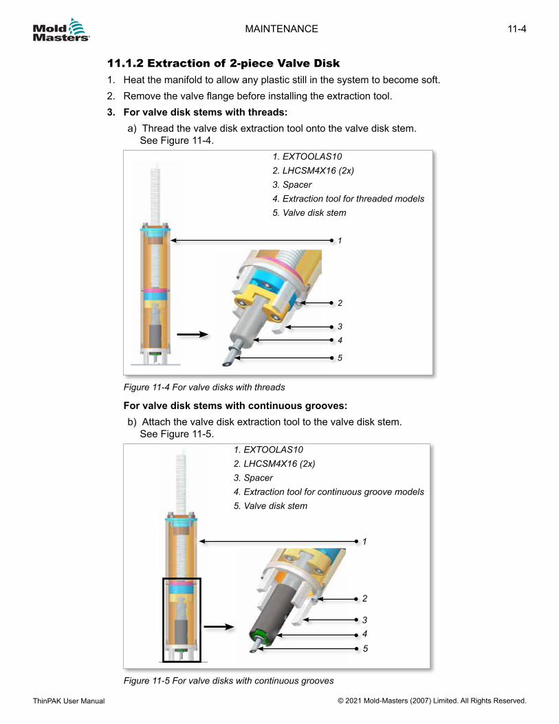
11.1.2 Extraction of 2-piece Valve Disk1. Heat the manifold to allow any plastic still in the system to become soft.2. Remove the valve flange before installing the extraction tool.3. For valve disk stems with threads:
a) Thread the valve disk extraction tool onto the valve disk stem. See Figure 11-4.
1
2
34
1. EXTOOLAS102. LHCSM4X16 (2x)3. Spacer4. Extraction tool for threaded models5. Valve disk stem
5
Figure 11-4 For valve disks with threads
For valve disk stems with continuous grooves:b) Attach the valve disk extraction tool to the valve disk stem.
See Figure 11-5.
1
2
345
1. EXTOOLAS102. LHCSM4X16 (2x)3. Spacer4. Extraction tool for continuous groove models5. Valve disk stem
Figure 11-5 For valve disks with continuous grooves
11-4
© 2021 Mold-Masters (2007) Limited. All Rights Reserved.
MAINTENANCE
ThinPAK User Manual

4. Attach EXTOOLAS10 to the extraction tool for the valve disk stem.
NOTEFor close pitch conditions, use EXTOOLAS10 with a spacer.
5. Extract the valve disk from the manifold.
IMPORTANTEnsure that the pulling direction is perpendicular to the manifold surface.
11-5MAINTENANCE
ThinPAK User Manual © 2021 Mold-Masters (2007) Limited. All Rights Reserved.
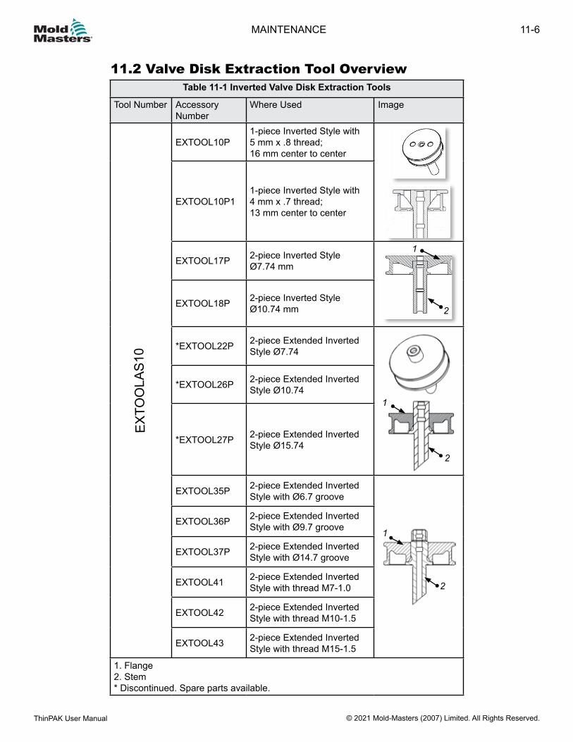
11.2 Valve Disk Extraction Tool OverviewTable 11-1 Inverted Valve Disk Extraction Tools
Tool Number Accessory Number
Where Used Image
EXTO
OLA
S10
EXTOOL10P1-piece Inverted Style with 5 mm x .8 thread;16 mm center to center
EXTOOL10P11-piece Inverted Style with 4 mm x .7 thread;13 mm center to center
EXTOOL17P 2-piece Inverted StyleØ7.74 mm
1
2EXTOOL18P 2-piece Inverted Style
Ø10.74 mm
*EXTOOL22P 2-piece Extended Inverted Style Ø7.74
2
1
*EXTOOL26P 2-piece Extended Inverted Style Ø10.74
*EXTOOL27P 2-piece Extended Inverted Style Ø15.74
EXTOOL35P 2-piece Extended Inverted Style with Ø6.7 groove
2
1EXTOOL36P 2-piece Extended Inverted
Style with Ø9.7 groove
EXTOOL37P 2-piece Extended Inverted Style with Ø14.7 groove
EXTOOL41 2-piece Extended Inverted Style with thread M7-1.0
EXTOOL42 2-piece Extended Inverted Style with thread M10-1.5
EXTOOL43 2-piece Extended Inverted Style with thread M15-1.5
1. Flange2. Stem* Discontinued. Spare parts available.
11-6
© 2021 Mold-Masters (2007) Limited. All Rights Reserved.
MAINTENANCE
ThinPAK User Manual
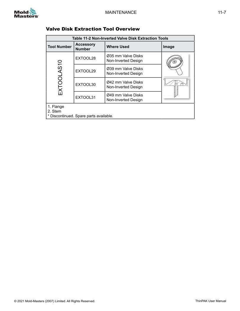
Valve Disk Extraction Tool Overview
Table 11-2 Non-Inverted Valve Disk Extraction Tools
Tool Number Accessory Number Where Used Image
EXTO
OLA
S10 EXTOOL28 Ø35 mm Valve Disks
Non-Inverted Design
EXTOOL29 Ø39 mm Valve Disks Non-Inverted Design
EXTOOL30 Ø42 mm Valve Disks Non-Inverted Design
EXTOOL31 Ø49 mm Valve Disks Non-Inverted Design
1. Flange2. Stem* Discontinued. Spare parts available.
11-7MAINTENANCE
ThinPAK User Manual © 2021 Mold-Masters (2007) Limited. All Rights Reserved.
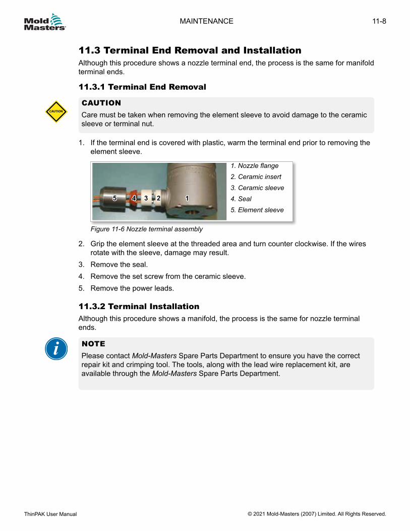
11.3 Terminal End Removal and InstallationAlthough this procedure shows a nozzle terminal end, the process is the same for manifold terminal ends.
11.3.1 Terminal End Removal
CAUTIONCare must be taken when removing the element sleeve to avoid damage to the ceramic sleeve or terminal nut.
CAUTION
1. If the terminal end is covered with plastic, warm the terminal end prior to removing the element sleeve.
1. Nozzle flange2. Ceramic insert3. Ceramic sleeve4. Seal5. Element sleeve
22 11334455
Figure 11-6 Nozzle terminal assembly
2. Grip the element sleeve at the threaded area and turn counter clockwise. If the wires rotate with the sleeve, damage may result.
3. Remove the seal.4. Remove the set screw from the ceramic sleeve.5. Remove the power leads.
11.3.2 Terminal InstallationAlthough this procedure shows a manifold, the process is the same for nozzle terminal ends.
NOTEPlease contact Mold-Masters Spare Parts Department to ensure you have the correct repair kit and crimping tool. The tools, along with the lead wire replacement kit, are available through the Mold-Masters Spare Parts Department.
11-8
© 2021 Mold-Masters (2007) Limited. All Rights Reserved.
MAINTENANCE
ThinPAK User Manual
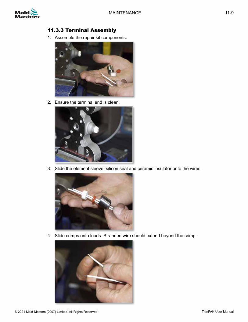
11.3.3 Terminal Assembly1. Assemble the repair kit components.
2. Ensure the terminal end is clean.
3. Slide the element sleeve, silicon seal and ceramic insulator onto the wires.
4. Slide crimps onto leads. Stranded wire should extend beyond the crimp.
11-9MAINTENANCE
ThinPAK User Manual © 2021 Mold-Masters (2007) Limited. All Rights Reserved.
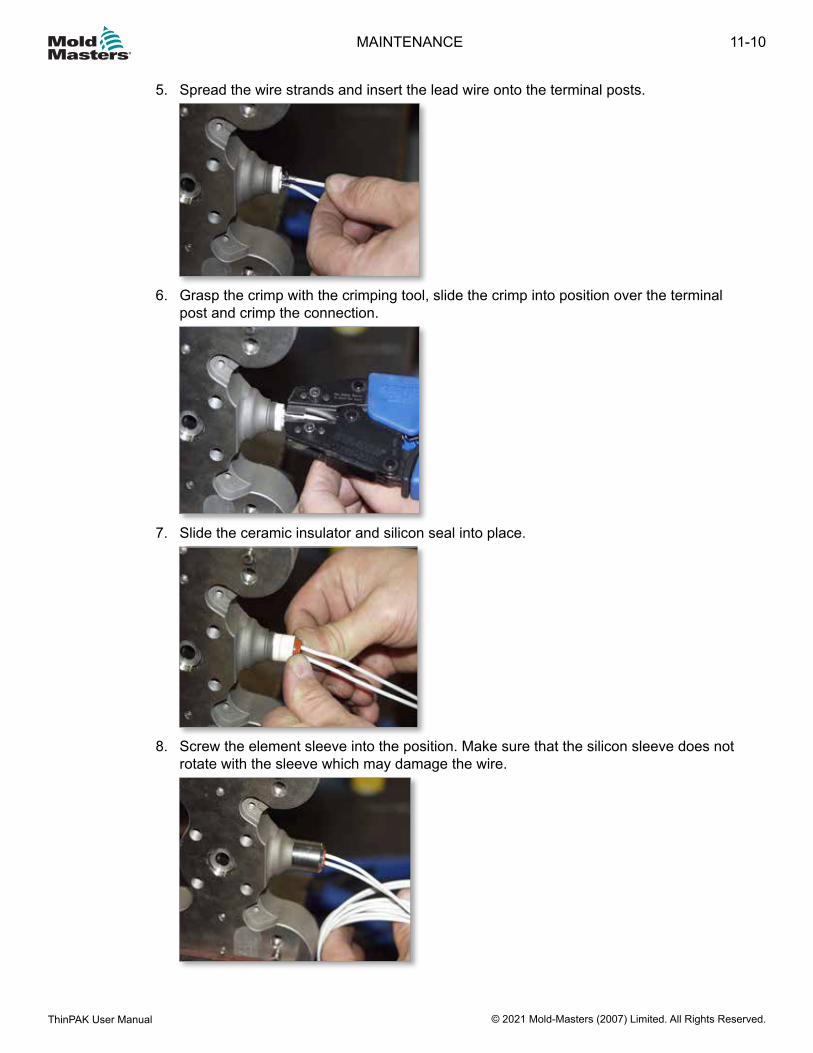
5. Spread the wire strands and insert the lead wire onto the terminal posts.
6. Grasp the crimp with the crimping tool, slide the crimp into position over the terminal post and crimp the connection.
7. Slide the ceramic insulator and silicon seal into place.
8. Screw the element sleeve into the position. Make sure that the silicon sleeve does not
rotate with the sleeve which may damage the wire.
11-10
© 2021 Mold-Masters (2007) Limited. All Rights Reserved.
MAINTENANCE
ThinPAK User Manual

Table 11-3 Crimping Tool Chart
Product Name DescriptionPUNCHHANDLE01 Ratchet tool for securing crimp to terminal end assembliesCRIMPDIE01 4.0 mm Heater Element
(Mates with CRIMPPUNCH01)CRIMPPUNCH01 4.0 mm Heater Element
(Mates with CRIMPDIE01)CRIMPDIE02 2.5 - 3.0 mm Heater Element
(Mates with CRIMPPUNCH02)CRIMPPUNCH02 2.5 - 3.0 mm Heater Element
(Mates with CRIMPDIE02)CRIMPDIE03 1.8 - 2.0 mm Heater Element
(Mates with CRIMPPUNCH03)CRIMPPUNCH03 1.8 - 2.0 mm Heater Element
(Mates with CRIMPDIE03)CRIMPREMOVEB01 Bottom Crimp Removal Insert for shearing HE crimps
(Mates with CRIMPREMOVET01)CRIMPREMOVET01 Top Crimp Removal Insert for shearing HE crimps
(Mates with CRIMPREMOVEB01)
11-11MAINTENANCE
ThinPAK User Manual © 2021 Mold-Masters (2007) Limited. All Rights Reserved.
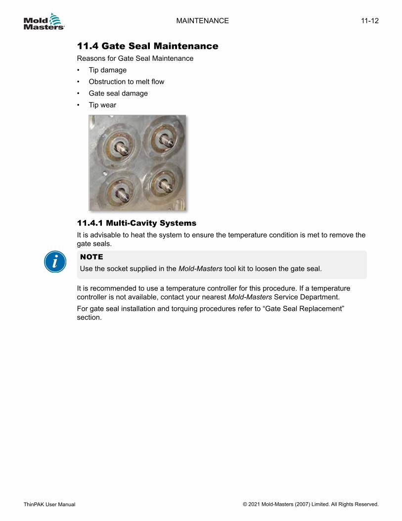
11.4 Gate Seal MaintenanceReasons for Gate Seal Maintenance• Tip damage• Obstruction to melt flow• Gate seal damage• Tip wear
11.4.1 Multi-Cavity SystemsIt is advisable to heat the system to ensure the temperature condition is met to remove the gate seals.
NOTEUse the socket supplied in the Mold-Masters tool kit to loosen the gate seal.
It is recommended to use a temperature controller for this procedure. If a temperature controller is not available, contact your nearest Mold-Masters Service Department.For gate seal installation and torquing procedures refer to “Gate Seal Replacement” section.
11-12
© 2021 Mold-Masters (2007) Limited. All Rights Reserved.
MAINTENANCE
ThinPAK User Manual
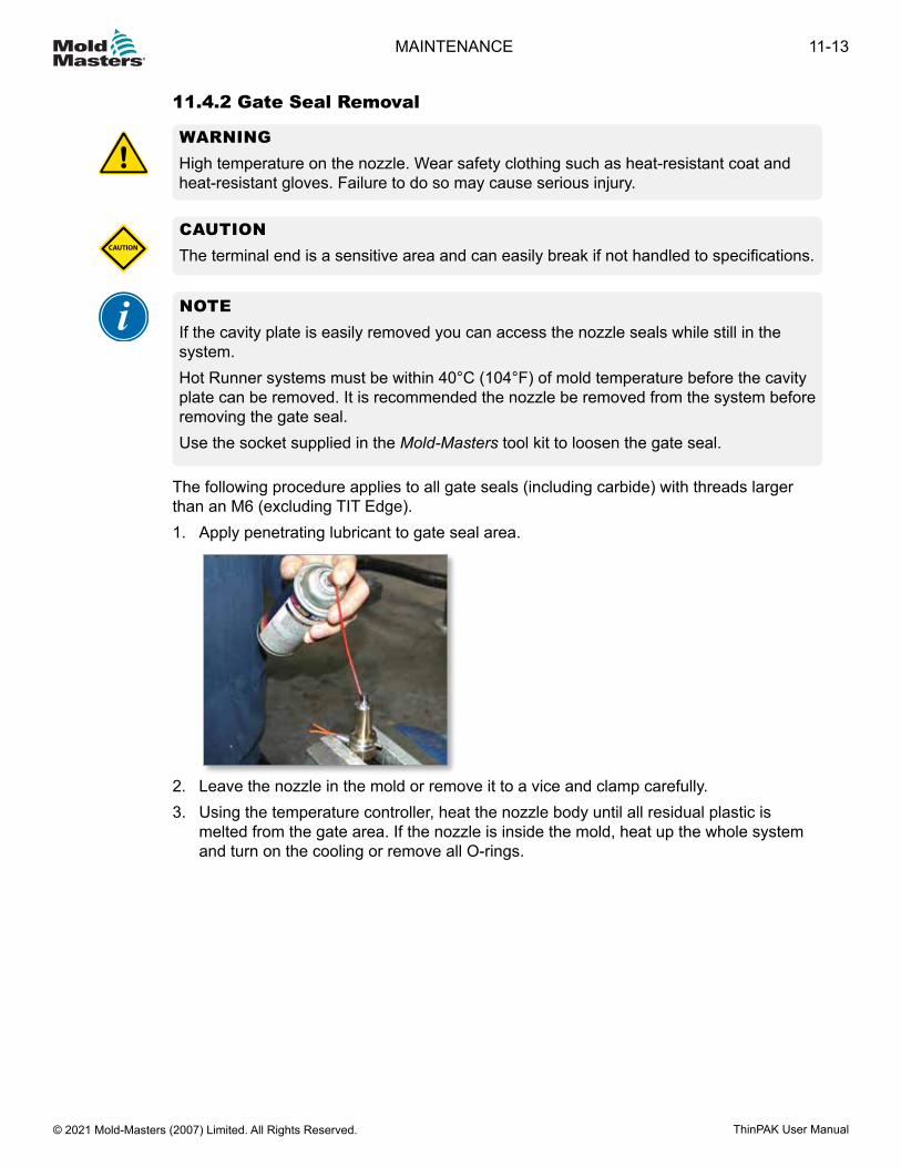
11.4.2 Gate Seal Removal
WARNING High temperature on the nozzle. Wear safety clothing such as heat-resistant coat and heat-resistant gloves. Failure to do so may cause serious injury.
CAUTIONThe terminal end is a sensitive area and can easily break if not handled to specifications.CAUTION
NOTE If the cavity plate is easily removed you can access the nozzle seals while still in the system. Hot Runner systems must be within 40°C (104°F) of mold temperature before the cavity plate can be removed. It is recommended the nozzle be removed from the system before removing the gate seal.Use the socket supplied in the Mold-Masters tool kit to loosen the gate seal.
The following procedure applies to all gate seals (including carbide) with threads larger than an M6 (excluding TIT Edge).1. Apply penetrating lubricant to gate seal area.
2. Leave the nozzle in the mold or remove it to a vice and clamp carefully.3. Using the temperature controller, heat the nozzle body until all residual plastic is
melted from the gate area. If the nozzle is inside the mold, heat up the whole system and turn on the cooling or remove all O-rings.
11-13MAINTENANCE
ThinPAK User Manual © 2021 Mold-Masters (2007) Limited. All Rights Reserved.
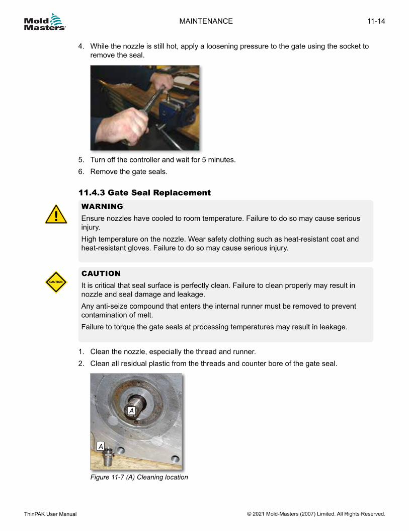
4. While the nozzle is still hot, apply a loosening pressure to the gate using the socket to remove the seal.
5. Turn off the controller and wait for 5 minutes.6. Remove the gate seals.
11.4.3 Gate Seal ReplacementWARNINGEnsure nozzles have cooled to room temperature. Failure to do so may cause serious injury.High temperature on the nozzle. Wear safety clothing such as heat-resistant coat and heat-resistant gloves. Failure to do so may cause serious injury.
CAUTIONIt is critical that seal surface is perfectly clean. Failure to clean properly may result in nozzle and seal damage and leakage.Any anti-seize compound that enters the internal runner must be removed to prevent contamination of melt.Failure to torque the gate seals at processing temperatures may result in leakage.
CAUTION
1. Clean the nozzle, especially the thread and runner.2. Clean all residual plastic from the threads and counter bore of the gate seal.
A
A
Figure 11-7 (A) Cleaning location
11-14
© 2021 Mold-Masters (2007) Limited. All Rights Reserved.
MAINTENANCE
ThinPAK User Manual
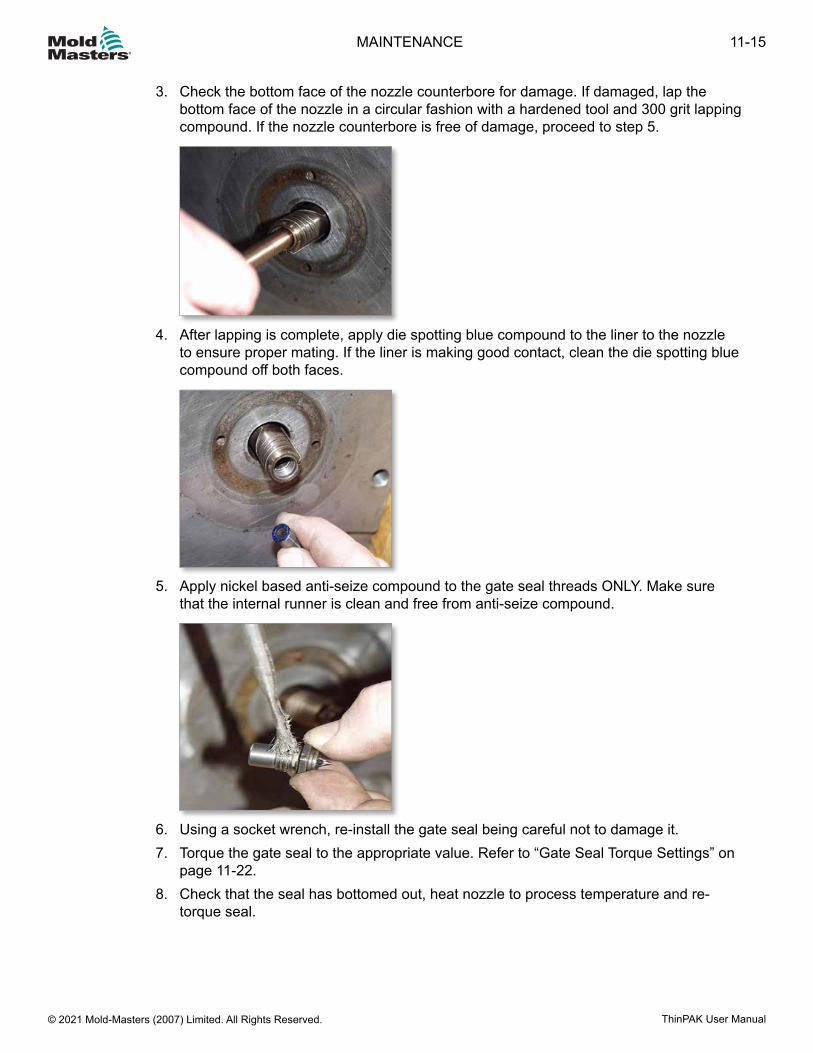
3. Check the bottom face of the nozzle counterbore for damage. If damaged, lap the bottom face of the nozzle in a circular fashion with a hardened tool and 300 grit lapping compound. If the nozzle counterbore is free of damage, proceed to step 5.
4. After lapping is complete, apply die spotting blue compound to the liner to the nozzle to ensure proper mating. If the liner is making good contact, clean the die spotting blue compound off both faces.
5. Apply nickel based anti-seize compound to the gate seal threads ONLY. Make sure
that the internal runner is clean and free from anti-seize compound.
6. Using a socket wrench, re-install the gate seal being careful not to damage it.7. Torque the gate seal to the appropriate value. Refer to “Gate Seal Torque Settings” on
page 11-22.8. Check that the seal has bottomed out, heat nozzle to process temperature and re-
torque seal.
11-15MAINTENANCE
ThinPAK User Manual © 2021 Mold-Masters (2007) Limited. All Rights Reserved.
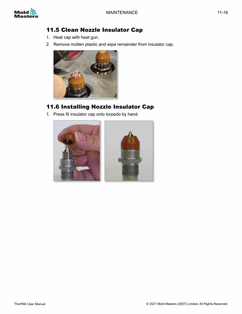
11.5 Clean Nozzle Insulator Cap1. Heat cap with heat gun.2. Remove molten plastic and wipe remainder from insulator cap.
11.6 Installing Nozzle Insulator Cap1. Press fit insulator cap onto torpedo by hand.
11-16
© 2021 Mold-Masters (2007) Limited. All Rights Reserved.
MAINTENANCE
ThinPAK User Manual
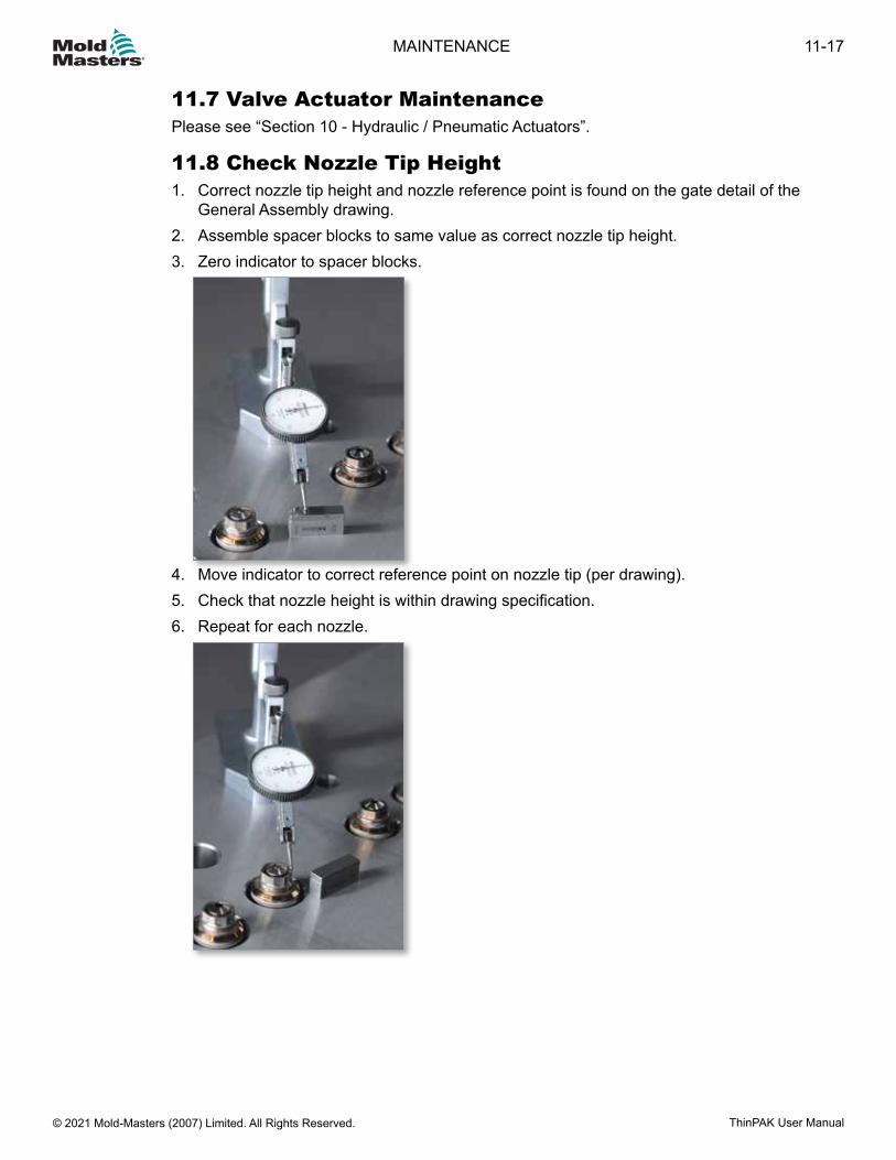
11.7 Valve Actuator MaintenancePlease see “Section 10 - Hydraulic / Pneumatic Actuators”.
11.8 Check Nozzle Tip Height1. Correct nozzle tip height and nozzle reference point is found on the gate detail of the
General Assembly drawing.2. Assemble spacer blocks to same value as correct nozzle tip height.3. Zero indicator to spacer blocks.
4. Move indicator to correct reference point on nozzle tip (per drawing).5. Check that nozzle height is within drawing specification.6. Repeat for each nozzle.
11-17MAINTENANCE
ThinPAK User Manual © 2021 Mold-Masters (2007) Limited. All Rights Reserved.
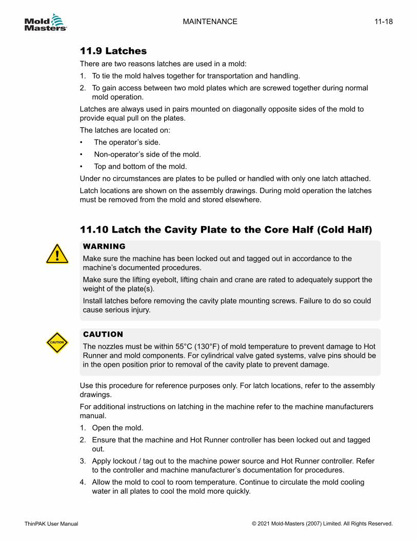
11.9 LatchesThere are two reasons latches are used in a mold:1. To tie the mold halves together for transportation and handling.2. To gain access between two mold plates which are screwed together during normal
mold operation.Latches are always used in pairs mounted on diagonally opposite sides of the mold to provide equal pull on the plates.The latches are located on:• The operator’s side.• Non-operator’s side of the mold.• Top and bottom of the mold.Under no circumstances are plates to be pulled or handled with only one latch attached.Latch locations are shown on the assembly drawings. During mold operation the latches must be removed from the mold and stored elsewhere.
11.10 Latch the Cavity Plate to the Core Half (Cold Half)WARNING Make sure the machine has been locked out and tagged out in accordance to the machine’s documented procedures.Make sure the lifting eyebolt, lifting chain and crane are rated to adequately support the weight of the plate(s).Install latches before removing the cavity plate mounting screws. Failure to do so could cause serious injury.
CAUTION The nozzles must be within 55°C (130°F) of mold temperature to prevent damage to Hot Runner and mold components. For cylindrical valve gated systems, valve pins should be in the open position prior to removal of the cavity plate to prevent damage.
CAUTION
Use this procedure for reference purposes only. For latch locations, refer to the assembly drawings.For additional instructions on latching in the machine refer to the machine manufacturers manual. 1. Open the mold.2. Ensure that the machine and Hot Runner controller has been locked out and tagged
out.3. Apply lockout / tag out to the machine power source and Hot Runner controller. Refer
to the controller and machine manufacturer’s documentation for procedures.4. Allow the mold to cool to room temperature. Continue to circulate the mold cooling
water in all plates to cool the mold more quickly.
11-18
© 2021 Mold-Masters (2007) Limited. All Rights Reserved.
MAINTENANCE
ThinPAK User Manual
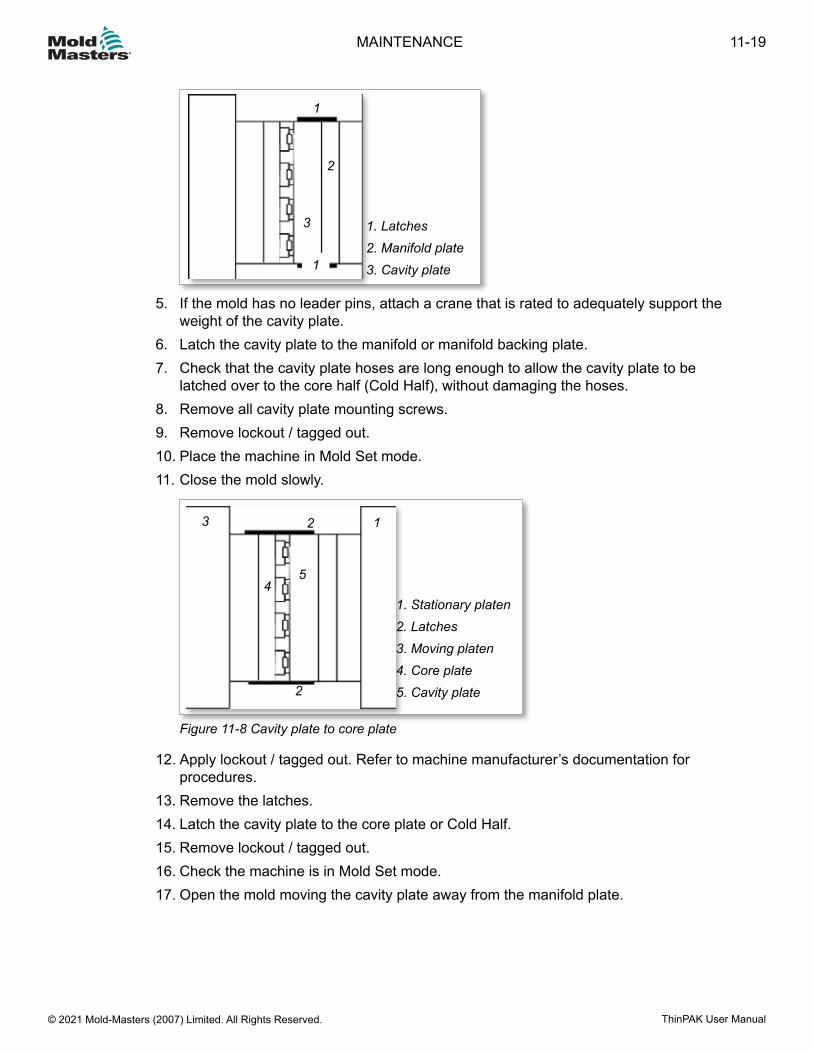
1. Latches2. Manifold plate3. Cavity plate1
1
2
3
5. If the mold has no leader pins, attach a crane that is rated to adequately support the weight of the cavity plate.
6. Latch the cavity plate to the manifold or manifold backing plate.7. Check that the cavity plate hoses are long enough to allow the cavity plate to be
latched over to the core half (Cold Half), without damaging the hoses.8. Remove all cavity plate mounting screws.9. Remove lockout / tagged out.10. Place the machine in Mold Set mode.11. Close the mold slowly.
12
2
3
45
1. Stationary platen2. Latches3. Moving platen4. Core plate5. Cavity plate
Figure 11-8 Cavity plate to core plate
12. Apply lockout / tagged out. Refer to machine manufacturer’s documentation for procedures.
13. Remove the latches.14. Latch the cavity plate to the core plate or Cold Half.15. Remove lockout / tagged out.16. Check the machine is in Mold Set mode.17. Open the mold moving the cavity plate away from the manifold plate.
11-19MAINTENANCE
ThinPAK User Manual © 2021 Mold-Masters (2007) Limited. All Rights Reserved.
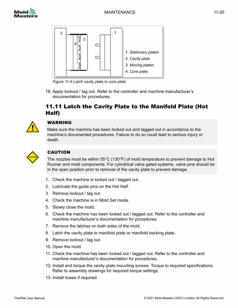
1. Stationary platen 2. Cavity plate3. Moving platen4. Core plate
1
23
4
Figure 11-9 Latch cavity plate to core plate
18. Apply lockout / tag out. Refer to the controller and machine manufacturer’s documentation for procedures.
11.11 Latch the Cavity Plate to the Manifold Plate (Hot Half)WARNINGMake sure the machine has been locked out and tagged out in accordance to the machine’s documented procedures. Failure to do so could lead to serious injury or death.
CAUTION The nozzles must be within 55°C (130°F) of mold temperature to prevent damage to Hot Runner and mold components. For cylindrical valve gated systems, valve pins should be in the open position prior to removal of the cavity plate to prevent damage.
CAUTION
1. Check the machine is locked out / tagged out.2. Lubricate the guide pins on the Hot Half.3. Remove lockout / tag out.4. Check the machine is in Mold Set mode.5. Slowly close the mold.6. Check the machine has been locked out / tagged out. Refer to the controller and
machine manufacturer’s documentation for procedures.7. Remove the latches on both sides of the mold.8. Latch the cavity plate to manifold plate or manifold backing plate.9. Remove lockout / tag out.10. Open the mold.11. Check the machine has been locked out / tagged out. Refer to the controller and
machine manufacturer’s documentation for procedures.12. Install and torque the cavity plate mounting screws. Torque to required specifications.
Refer to assembly drawings for required torque settings.13. Install hoses if required.
11-20
© 2021 Mold-Masters (2007) Limited. All Rights Reserved.
MAINTENANCE
ThinPAK User Manual
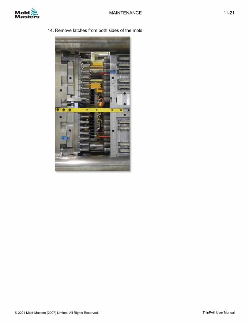
14. Remove latches from both sides of the mold.
11-21MAINTENANCE
ThinPAK User Manual © 2021 Mold-Masters (2007) Limited. All Rights Reserved.
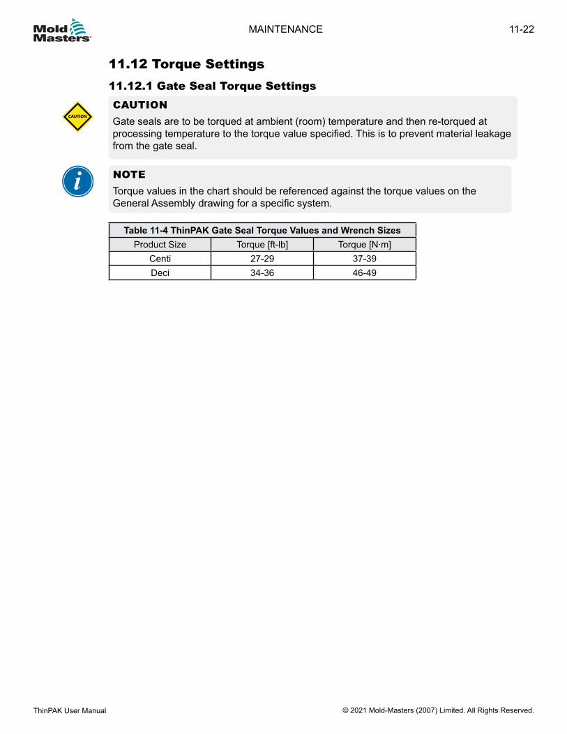
Table 11-4 ThinPAK Gate Seal Torque Values and Wrench SizesProduct Size Torque [ft-lb] Torque [N∙m]
Centi 27-29 37-39Deci 34-36 46-49
11.12 Torque Settings11.12.1 Gate Seal Torque SettingsCAUTIONGate seals are to be torqued at ambient (room) temperature and then re-torqued at processing temperature to the torque value specified. This is to prevent material leakage from the gate seal.
CAUTION
NOTETorque values in the chart should be referenced against the torque values on the General Assembly drawing for a specific system.
11-22
© 2021 Mold-Masters (2007) Limited. All Rights Reserved.
MAINTENANCE
ThinPAK User Manual
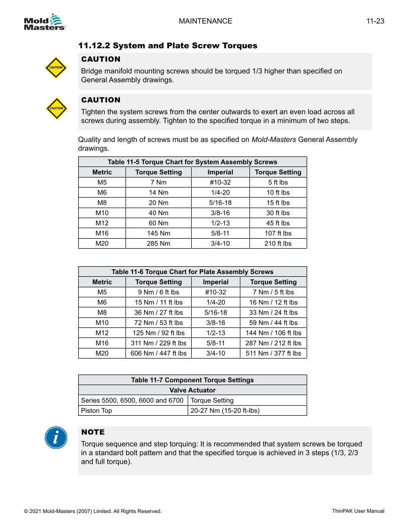
11.12.2 System and Plate Screw TorquesCAUTIONBridge manifold mounting screws should be torqued 1/3 higher than specified on General Assembly drawings.
CAUTION
CAUTIONTighten the system screws from the center outwards to exert an even load across all screws during assembly. Tighten to the specified torque in a minimum of two steps.
CAUTION
Quality and length of screws must be as specified on Mold-Masters General Assembly drawings.
Table 11-5 Torque Chart for System Assembly ScrewsMetric Torque Setting Imperial Torque Setting
M5 7 Nm #10-32 5 ft lbsM6 14 Nm 1/4-20 10 ft lbsM8 20 Nm 5/16-18 15 ft lbs
M10 40 Nm 3/8-16 30 ft lbsM12 60 Nm 1/2-13 45 ft lbsM16 145 Nm 5/8-11 107 ft lbsM20 285 Nm 3/4-10 210 ft lbs
Table 11-6 Torque Chart for Plate Assembly ScrewsMetric Torque Setting Imperial Torque Setting
M5 9 Nm / 6 ft lbs #10-32 7 Nm / 5 ft lbsM6 15 Nm / 11 ft lbs 1/4-20 16 Nm / 12 ft lbsM8 36 Nm / 27 ft lbs 5/16-18 33 Nm / 24 ft lbsM10 72 Nm / 53 ft lbs 3/8-16 59 Nm / 44 ft lbsM12 125 Nm / 92 ft lbs 1/2-13 144 Nm / 106 ft lbsM16 311 Nm / 229 ft lbs 5/8-11 287 Nm / 212 ft lbsM20 606 Nm / 447 ft lbs 3/4-10 511 Nm / 377 ft lbs
Table 11-7 Component Torque SettingsValve Actuator
Series 5500, 6500, 6600 and 6700 Torque SettingPiston Top 20-27 Nm (15-20 ft-lbs)
NOTETorque sequence and step torquing: It is recommended that system screws be torqued in a standard bolt pattern and that the specified torque is achieved in 3 steps (1/3, 2/3 and full torque).
11-23MAINTENANCE
ThinPAK User Manual © 2021 Mold-Masters (2007) Limited. All Rights Reserved.
Section 12 - TroubleshootingMolding is a complicated process with many variables to consider. If you are having problems, take a step-by-step systematic approach to find a solution that optimizes the process.Some basic rules for troubleshooting:
• Define the problem; what is observed is only a symptom of the underlying problem.
• Develop a method to isolate the problem.• Test one item at a time to verify results.• Monitor the final solution to verify that the problem has been solved. Repeat
occurrences of the same symptom may indicate other problems.• Document the solution so that a repeat occurrence can be solved quickly.• Consult other resources to augment the troubleshooting information in the
attached guide. One of the best resources may be your resin supplier.
To help in this process, we welcome you to reference Mold-Masters Troubleshooting Guide which offers general information related to common issues. This document can be found at https://www.moldmasters.com/support/troubleshooting. If you cannot find your issue within the documentation and continue to have problems, please contact your local Mold-Masters hot runner expert for assistance.
12-1TROUBLESHOOTING
ThinPAK User Manual © 2021 Mold-Masters (2007) Limited. All Rights Reserved.
Section 13 - GlossaryEDM: Electrical discharge machiningTERMCON: Terminal connectorAspect Ratio: Ratio of total flow length to average wall thickness.Back Pressure: The pressure applied to the plastic during screw recovery. By increasing back pressure, mixing and plasticating are improved; however, screw recovery rates are reduced.Backplate: Inlet component to the Hot Runner manifold.Barrel: The part of the molding press where resin is melted.B-side: The mold half that mounts to the moving side of the injection molding press. Sometimes referred to as the core side of the mold or the Cold Half, the B-side has ejector pins to push the part out of the open mold. An analysis of the part geometry determines the optimal part orientation to ensure that it will remain on the B-side when the mold is openedCast-in Heater Element: A heater element that is brazed in the manifold.Clamp Force: The force required to hold the mold shut so resin cannot escape during injection.Con.: ConnectorContoured Pins: Ejector pins with the ends shaped to match a sloping surface on the part.Core: A convex feature on either side of the mold that will enter an opposing cavity when the mold is closed. The void between the cavity and core is where the resin solidifies and forms the part. Often the B-side of a mold is referred to as the core side.Core-cavity: The design of a mold where the A-side forms the outside of the part and the B-side forms the inside. The advantage to this approach is that the part will shrink onto the B-side so it can be ejected, and if the inside and outside are drafted with equal and opposite draft the wall thickness will be constant.Cycle Time: The time it takes to make one part including the closing of the mold, the injection of the resin, the solidification of the part, the opening of the mold and the ejection of the part.Cavity: The space inside a mold into which material is injected.Clamp: The part of an injection molding machine incorporating the platens that provides the force necessary to hold the mold closed during injection of the molten resin and open the mold to eject the molded part.Clamping Plate: A plate fitted to a mold and used to fasten the mold to a platen.Clamping Pressure: The pressure applied to the mold to keep it closed during a cycle, usually expressed in tons.Closed-loop Control: System for monitoring complete, injection molding- process conditions of temperature, pressure and time, and automatically making any changes required to keep part production within preset tolerances.Cooling Channels: Channels located within the body of a mold through which a cooling medium is circulated to control the mold surface temperature.
13-1GLOSSARY
ThinPAK User Manual © 2021 Mold-Masters (2007) Limited. All Rights Reserved.
Cushion: Extra material left in barrel during cycle to try and ensure that the part is packed out during the hold time.Cycle: The complete sequence of operations in a process to complete one set of moldings. The cycle is taken at a point in the operation and ends when this point is again reached and moving platens of the clamp unit in the fully open position.Cycle Time: The time required by an injection molding system to mold a part.Dwell: A pause in the applied pressure to a mold during the injection cycle just before the mold is completely closed. This dwell allows any gases formed or present to escape from the molding material.Ejector Pins: Pins that are pushed into a mold cavity from the rear as the mold opens to force the finished part out of the mold. Also called knockout pins.Ejector Return Pins: Projections that push the ejector assembly back as the mold closes. Also called surface pins or return pins.Ejector Rod: A bar that actuates the ejector assembly when the mold opens.Family Mold: A multi-cavity mold where each of the cavities forms one of the component parts of an assembled finished part.Fleeting angle: The angle at which the belt enters and exits the pulleys; it equals the sum of the parallel and angular misalignments.Fill: The packing of the cavity or cavities of the mold as required to give a complete part or parts that are free of flash.Flow: A qualitative description of the fluidity of a plastic material during the process of molding. A measure of its moldability generally expressed as melt flow rate or melt index.Gate: An opening through which the melt enters the mold cavity.Hot Tip Gate: An injection molding method that uses a heated gate on the A-side of the part to eliminate the creation of any runner or sprue. The gate vestige will be a small sharp bump that can be trimmed if necessary.Hot Runner Mold: A mold in which the runners are insulated from the chilled cavities and are kept hot. Hot Runner molds make parts that have no scrap.Inseal: Inlet sealInjection: The process of forcing melted resin into a mold.Injection Pressure: The pressure on the face of the injection screw or ram when injecting material into the mold, usually expressed in PSI or BAR.Knockout Pins: A rod or device for knocking a finished part out of a mold.Land: The walls of the gate, parallel or angled to the molding surface.L/D Ratio: A term used to help define an injection screw. This is the screw length-to-diameter ratio.Manifolds: distribute melt from the inlet component to one or more submanifolds within a Hot Runner.Melt Flow Rate: A measure of the molten viscosity of a polymer determined by the weight of polymer extruded through an orifice under specified conditions of pressure and temperature. Particular conditions are dependent upon the type of polymer being tested. MFR usually is reported in grams per 10 minutes. Melt flow rate defines the flow of a polypropylene resin. An extrusion weight of 2160 grams at 446°F (230°C) is used.
13-2
© 2021 Mold-Masters (2007) Limited. All Rights Reserved.
GLOSSARY
ThinPAK User Manual
Melt Flow Index: Term that defines the melt flow rate of a polyethylene resin. An extrusion weight of 2160 grams at 310°F (190°C) is used.Mold: A series of machined steel plates containing cavities into which plastic resin is injected to form a part.Mold Frame: A series of steel plates which contain mold components, including cavities, cores, runner system, cooling system, ejection system, etc.Mold-Temperature-Control Unit: Auxiliary equipment used to control Hot Runner temperature. Some units can both heat and cool the mold. Others, called chillers, only cool the mold.Moving Platen: The platen of an injection molding machine that is moved by a hydraulic ram or mechanical toggle.Multi-Cavity Mold: A mold having two or more impressions for forming finished items in one machine cycle.Multi-Material Molding: The injection of two-or-more materials, in sequence, into a single mold during a single molding cycle. The injection molding machine is equipped with two-or-more plasticators. (See also co-injection)Nest Plate: A retainer plate in the mold with a depressed area for cavity blocks.Non-Fill: See short shot.Non-Return Valve: Screw tip that allows for material to flow in one direction and then closes to prevent backflow during injection.Machine Nozzle: The hollow-cored, metal nose screwed into the injection end of a plasticator. The nozzle matches the depression in the mold. This nozzle allows transfer of the melt from the plasticator to the runner system and cavities.Packing: The filling of the mold cavity or cavities as full as possible without causing undue stress on the molds or causing flash to appear on the finished parts. Over- or under-packing results in less than optimum fill.PET: Polyethylene Terephthalate, a type of polyester and a leading recyclable plastic material.Pinpoint Gate: A restricted gate of 0.030 in. or less in diameter, this gate is common on Hot Runner molds.Platens: The mounting plates of a press on which the mold halves are attached.Pressure Disk: Manifold component designed to be compressed by thermal expansive forces to form part of the plastic sealing mechanism. Also helps to reduce thermal transfer to a minimum.Process: The injection molding environment consisting of input variables such as temperature, pressure, injection rates and time that are controlled to fill the mold while optimizing the trade-offs between cosmetics and dimensional accuracy.Ram: The forward motion of the screw in the barrel that forces the melt into the mold cavity.Recovery Time: The length of time for the screw to rotate and create a shot.Retainer Plate: The plate on which demountable pieces, such as mold cavities, ejector pins, guide pins and bushings are mounted during molding.Ring Gate: Used on some cylindrical shapes. This gate encircles the core to permit the
13-3GLOSSARY
ThinPAK User Manual © 2021 Mold-Masters (2007) Limited. All Rights Reserved.
melt to first move around the core before filling the cavity.Runner: The channel that connects the sprue with the gate for transferring the melt to the cavities.Runnerless Molding: See Hot Runner mold.Scrap: Parts that do not meet the quality standards.Screw Travel: The distance the screw travels forward when filling the mold cavity.Shear: The force between layers of resin as they slide against each other or the surface of the mold. The resulting friction causes some heating of the resin.Short Shot: Failure to completely fill the part or cavities of the mold. Edges may appear melted.Shot: The complete amount of melt injected during a molding cycle, including that which fills the runner system.Shot Capacity: Generally based on polystyrene, this is the maximum weight of plastic that can be displaced or injected by a single injection stroke. Generally expressed as ounces of polystyrene.Single-Cavity Mold: A mold having only one cavity and producing only one finished part per cycle.Sprue Bushing: A hardened-steel insert in the mold that accepts the Screw nozzle and provides an opening for transferring the melt.Sprue Gate: A passageway through which melt flows from the nozzle to the mold cavity.Sprue: The feed opening provided in injection molding between the nozzle and cavity or runner system.Stationary Platen: The large front plate of an injection molding press to which the front plate of the mold is secured. This platen does not move during normal operation.Step: A transition component that provides a slight separation between the bridge and the manifold and that allows the melt passage to connect the bridge and manifold.Thermal gate: A gate that is closed by temperature. Resin solidifies in the gate to block resin from flowing out of the hot runner.Thermoplastic: A polymer which melts or flows when heated. Thermoplastic polymers are usually not highly cross-linked, and act much like molecular solids: low melting and boiling points, high ductile strength.Thermoset: A polymer that does not melt when heated. Thermoset polymers “set” into a given shape when first made and afterwards do not flow or melt, but rather decompose upon heating. They are often highly cross-linked polymers, with properties similar to those of network covalent solids, i.e., hard and strong.Valve Disk: Manifold component designed to be compressed by thermal expansive forces to form part of the plastic sealing mechanism. Its high tolerance bore allows the valve pin to shift through it without plastic leakage and part of it enters the melt stream and helps guide the plastic flow without stagnation.Valve Gating: An injection molding method that uses a mechanical shut off to open and close the gate orifice.Vent: A shallow channel or opening cut in the cavity to allow air or gases to escape as the melt fills the cavity.Some glossary content © DRM Associates 2008 / © Protomold 1999-2009
13-4
© 2021 Mold-Masters (2007) Limited. All Rights Reserved.
GLOSSARY
ThinPAK User Manual

IndexAAssembly (Center Section) 13-5
BBack Up Ring 10-2Bridged Hydraulic Pneumatic System 4-6
CCast-in Heater Element System 4-4Checking Nozzle Tip Height 15-19Cleaning 4-3Cleaning Nozzle Insulator Cap 15-18Components 13-3
EExtraction Tool 10-22, 10-23
FFix Idler 13-3–IV
GGate Seal Finishing
Hot Valve / Hot Sprue / F Type 5-4Glossary of Terms 21-1Ground Shorts Test 6-2
HHazard Areas 3-2Heater Continuity 6-4Hydraulic or Pneumatic System 4-5
IInlet Extension With Pressure Sleeve 5-38Intended Use 1-1
LLatching 15-20
MMagnets 14-5Misalignment 13-15Motor Mount 13-3–IV
N
Nozzle Insulator Cap - Cleaning 15-18Nozzle Insulator Cap - Installing 15-18Nozzle Tip Height - Checking 15-19
PPre-Drying Resin 20-2Pre-Molding Precautions 20-2Pressure Disk 5-24
RRelease Details, Document 1-1Resin Drying Issues 20-1Resin Moisture Contamination 20-1
SSafety
Hazard Areas 3-2Lockout 3-10
Safety SymbolsGeneral Descriptions 3-7, 3-8, 3-13
TTemperatures 13-4–IVTensioning Idler Assembly 13-3–IVTerminal Assembly 15-9Thermocouple Continuity Test 6-3Three Piece Center Heater Installation 5-36Torque Settings 15-24Troubleshooting 20-1
VValve Actuators
Cylinder Bottom Assembly 10-2Cylinder Top Assembly 10-3Maintenance Procedure 10-20, 10-21Valve Pin Finishing of Tip 10-4
5500 Series 10-47100 Series 10-6, 10-8, 10-9
Valve Disk 5-24, 5-29Valve Disk Removal 15-1Valve Pin Assembly 10-11Valve Pin Lapping Procedure for Tapered Valve Pins
10-10
WWarranty 1-1Water Cooled Gate Insert Installation 5-4
ThinPAK User Manual © 2021 Mold-Masters (2007) Limited. All Rights Reserved.
IINDEX


GLOBAL CONTACTS
NORTH AMERICACANADA (Global HQ)tel: +1 905 877 0185e: [email protected]
SOUTH AMERICABRAZIL (Regional HQ)tel: +55 19 3518 4040e: [email protected]
EUROPEGERMANY (Regional HQ)tel: +49 7221 50990e: [email protected]
SPAINtel: +34 93 575 41 29e: [email protected]
FRANCEtel: +33 (0)1 78 05 40 20e: [email protected]
INDIAINDIA (Regional HQ)tel: +91 422 423 4888e: [email protected]
ASIACHINA (Regional HQ)tel: +86 512 86162882e: [email protected]
JAPANtel: +81 44 986 2101e: [email protected]
U.S.A.tel: +1 248 544 5710e: [email protected]
MEXICOtel: +52 442 713 5661 (sales) e: [email protected]
UNITED KINGDOMtel: +44 1432 265768e: [email protected]
POLANDtel: +48 669 180 888 (sales) e: [email protected]
TURKEYTel: +90 216 577 32 44e: [email protected]
KOREAtel: +82 31 431 4756e: [email protected]
AUSTRIAtel: +43 7582 51877 e: [email protected]
CZECH REPUBLICtel: +420 571 619 017e: [email protected]
ITALYtel: +39 049 501 99 55 e: [email protected]
SINGAPORE tel: +65 6261 7793e: [email protected]
© 2021 Mold-Masters (2007) Limited. All Rights Reserved.
ThinPAK® User Manual
www.moldmasters.com