timed discrete event control of parallel production lines with continuous outputs
TRANSCRIPT
Discrete Event Dyn Syst (2008) 18:241–262DOI 10.1007/s10626-007-0023-2
Timed Discrete Event Control of Parallel ProductionLines with Continuous Outputs
Stephanie Geist · Dmitry Gromov · Jörg Raisch
Received: 25 October 2006 / Accepted: 26 July 2007 /Published online: 15 August 2007© Springer Science + Business Media, LLC 2007
Abstract In this contribution we present an approach to formulate and solve certainscheduling tasks for hybrid systems using timed discrete event control methods.To demonstrate our approach, we consider a cyclically operated plant with parallelreactors using common resources and a continuous output. For this class of systems,we show how to pose the control problem within a discrete event frameworkby modelling system components as multirate timed automata. We propose asupervisory control strategy incorporating off-line optimisation to assure safety andnonconflicting use of resources. These properties have to be achieved in the presenceof a class of bounded errors/disturbances and can be verified by applying formalmethods.
Keywords Multirate timed automata · Scheduling · Parallel production lines ·Hybrid systems · Verification · Discrete event control
1 Introduction
Coordinating the interaction of components is an essential task in the control ofchemical production processes, particularly with regard to parallelised processes.
Work partially done in the framework of the HYCON Network of Excellence, contract numberFP6-IST-511368.
S. Geist (B) · D. Gromov · J. RaischFachgebiet Regelungssysteme, Technische Universität Berlin, Berlin, Germanye-mail: [email protected]
D. Gromove-mail: [email protected]
J. RaischSystems and Control Theory Group, Max-Planck-Institut für Dynamikkomplexer technischer Systeme, Magdeburg, Germanye-mail: [email protected]
242 Discrete Event Dyn Syst (2008) 18:241–262
In this context, scheduling problems aiming at the non-conflicting use of limitedresources are of crucial importance. In chemical industry, batch processes are oftenconnected to continuous processes by material supply and frequently the tasks ofcontinuous flow control and the nonconflicting use of resources cannot be decom-posed. In these cases the hybrid character of the plant cannot be neglected.
We present an approach to a scheduling problem guaranteeing the nonconflict-ing use of resources and safety despite disturbances using discrete event controlmethods. The approach combines standard off-line scheduling methods for batchprocessing and discrete event supervisory control which results in a flexible schedul-ing strategy for a class of cyclically operated plants.
In this contribution, we propose a control approach for a “parallelised” productionline with resource constraints and continuous output. The system consists of anarbitrary number of parallel batch reactors sharing an arbitrary number of resources,e.g., reactants, hot steam or cool water. The reactors are discharged into a sharedstorage tank or another continuously processed production unit that has a continuousoutflow which must not be interrupted. For this hybrid system, the goal is to assurenonconflicting work of the reactors and to prevent over- and underfilling of the tankin the presence of disturbances. Such a plant has been proposed as a case study withinthe EU Network of Excellence HYCON (Simeonova et al. 2005).
Solving the described problem in a monolithic way by the use of standardoptimisation-based scheduling methods (Méndez et al. 2006; Schilling and Pantelides1999) is hardly tractable for various reasons. Some constraints on the operationsequence require a continuous time formulation of events and most approachescannot deal with this; an exception is Wu and Ierapetritou (2004). Cyclically oper-ated plants may be very sensitive to disturbances, thus, frequent computationallyexpensive rescheduling is necessary in a standard framework. The major limitingfactors in the applicability of standard scheduling methods are the constraints on thestorage tank and its continuous outflow. Hence, material flow has to be consideredadditionally, and this makes the problem a hybrid one. Taking into account all theseconstraints, the described scheduling task results in a highly complex optimisationproblem. To overcome these difficulties, we propose a method that combines off-linescheduling and discrete event supervisory control in a hierarchical way. The feedbackstructure increases robustness under uncertainties, and hierarchical decompositioncan remarkably reduce the complexity of the problem.
The potential of discrete event methods for scheduling problems has been demon-strated in Abdeddaïm et al. (2006), Abdeddaïm and Maler (2001), Panek et al. (2006),Niebert and Yovine (2000), where timed automata have been used for modellingand solving job-shop scheduling problems by verification-based methods. Schedulingstrategies in the presence of uncertainties have been proposed in Abdeddaïm et al.(2006). In contrast to these publications, we consider cyclically operated plants andadditionally take continuous flows between the plant components into account. Forthe modelling of scheduling tasks in combination with continuous output flow controlwe use multirate timed automata.
To combine off-line optimisation and discrete event control, we formulate therequirement of nonconflicting use of resources by timed automata, where freeparameters can be optimised off-line with respect to a given cost function. Theresulting automata can be composed with other supervisor automata to enforce
Discrete Event Dyn Syst (2008) 18:241–262 243
the overall specifications. In this way, we can exploit feedback capabilities to avoidundesired behaviours and can use efficient off-line scheduling methods.
Describing scheduling problems in a timed automata framework is very intuitive.All system components including the resources can be considered as subsystemswhich can be easily described by timed automata and subsequently composed toform the overall problem. A major advantage of using timed automata methods formodelling is that controllers can be represented in the same formal framework. Thisfacilitates the use of formal methods, which, in contrast to heuristic methods, canguarantee desired properties. Standard tools and methods for verification of timedautomata are available and can be modified for multirate timed automata.
This contribution is an extended version of the conference paper (Gromov et al.2006) and is structured as follows: in Section 2, we give a formal description of theoverall problem. Multirate timed automata are introduced in Section 3. In Section 4,the modelling of the system components is described. In Section 5, we proposecontrol strategies to ensure safety and a non-conflicting performance. In Section 6, wediscuss verification techniques for problems described by multirate timed automata.Finally, in Section 7, we apply our approach to the HYCON benchmark described inSimeonova et al. (2005).
2 Problem statement
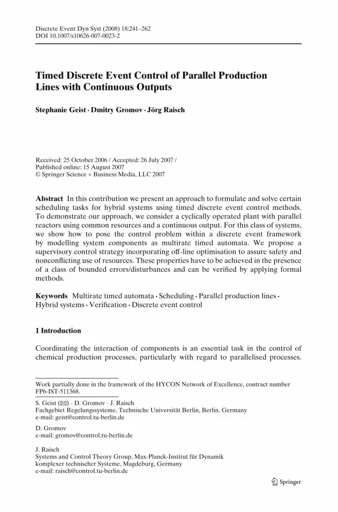
Figure 1 presents a schematic view of the chemical plant considered in the sequel.The system consists of n parallel batch reactors with k common resources, e.g., reac-
Fig. 1 A parallelisedproduction line with resourceconstraints
Res1
Reactor 1
Reactor n
Resk
244 Discrete Event Dyn Syst (2008) 18:241–262
tants, cold/hot water supplies and pumps. The reactors of volume V are dischargedinto one tank that acts as an output buffer and has the continuous output flow Fout,t.Only one reactor can be discharged at any instant of time. The volumetric flow Fout,r
during the discharging of a reactor is fixed, the output flow of the tank Fout,t canbe adjusted within a given range. In each reactor the same process is performed.The goal is to assure the nonconflicting use of resources and to keep the level ofthe tank volume between given values vmax and vmin. We assume that vmax > V.Furthermore, due to technological restrictions, the tank outflow once started maynot be interrupted.
A production cycle in the j-th reactor consists of a set of operations: Oj ={oij}, i = 1 . . . m, e.g., “heating,” “cooling,” “reaction,” “discharging” and so on. Thetemporal ordering of these operations is fixed and given by the index i. We assumethat there is efficient control of each operation, e.g. temperature control during theoperation “heating.” Thus, operations can be characterised by their processing timesdij. We will also consider varying processing times of operations for which an upperand lower bound is known: dij ∈ [d∗
i − d i; d∗i + di]. These deviations in processing
times may be caused by disturbances.There are a set of resources R and sets of “resource-sensitive” operations O′
j ⊂O j, j = 1, . . . , n. A map r j : O′
j → R associates a resource to each operation oij ∈ O′j
for reactor j. Here we assume that these maps are bijective, i.e. resources are usedonly once within the production cycle of a reactor.
Due to technological or safety requirements adjacent (in the temporal order) op-erations must sometimes be processed without delay. These operations are groupedinto tasks Kl
j = {olμj}, l = 1, 2 . . . ; p μ = 1, 2, . . . , where different tasks are disjoint,
i.e. Kl1j ∩ Kl2
j = ∅, for all l1 = l2. By requiring that each operation belongs to a task,we have
⋃
lKl
j = O j. We further require that each task contains at least one resource-
sensitive operation. This implies that an “isolated” operation also forms a task if itis resource-sensitive. Otherwise, it can be joined with the neighbour task. The indexμ describes the temporal ordering of operations within the task. Note that there isa fixed relation between the temporal position of an operation within the task andwithin the overall sequence of operations in the reactor. Each operation within a task
corresponds to an operation in the reactor cycle, olμj → oij where i =
l−1∑
q=1|Kq
j | + μ.
The goal of the control system to be designed is to assure cyclicity of the entireplant, i.e. safety requirements and the nonconflicting use of resources have to beguaranteed to avoid a shut-down of the plant. This has to be achieved in the presenceof disturbances characterised by varying operation durations. Furthermore, in thenominal case of fixed durations, the plant output has to be maximised, i.e. the controlsystem has to minimise the cycle duration. In the presence of disturbances, the cycleduration has to be minimised for a worst case scenario. Note that the worst case is apriori unknown.
The above assumptions can be relaxed without affecting our approach, but thiswould further complicate notation. For example, the approach can be generalisedand adapted to other plant structures, e.g. plants with several tanks with continuousoutflows, reactors processing different sequences of operations, and multiple use ofresources within a reactor cycle.
Discrete Event Dyn Syst (2008) 18:241–262 245
3 Multirate timed automata
Timed automata (Alur and Dill 1994) are finite automata augmented with a fi-nite set of continuous clocks whose values grow uniformly. Clocks can be resetindependently of each other at certain transitions. Transitions and locations canbe equipped with clock constraints representing continuous time information. Tomodel our problem adequately we need an extended class of timed automata, namelymultirate timed automata (Alur et al. 2000). In contrast to timed automata, clock ratesare not fixed, but may change when transitions occur.
Multirate timed automata are a special case of piece-wise linear hybrid systems,where the continuous dynamics are modelled by affine differential equations ineach location, e.g. Sontag (1996). In the context of our scheduling problem, theapproximation of material flow between plant components by integrators withswitched integration constants is sufficient. Therefore, multirate timed automata arethe simplest adequate class of models where formal methods can be applied andanalytical solutions can be obtained.
Multirate timed automata are formalised in the following definition.
Definition 1 A multirate timed automaton is a tuple A = (L, l0, �, X, x0, I, E, c, λ),where
• L is a finite set of locations,• l0 ∈ L is the initial location,• � is a finite set of events,• X is a finite set of clocks. A clock valuation for the set X is a real vector x ∈ R
|X|where xi is the value of the i-th element of X.
• x0 is the initial clock value.• I is a map that associates a clock constraint in �(x) to each location, i.e.
I : L → �(x), I(l) is called an invariant of l.• E ⊆ L × � × �(x) × L is a set of transitions, where transition e = (l, σ, φ, l′)
is a directed arc between locations l and l′ characterised by an event σ and aguard φ.
• c : L → Q|X| is a function that defines the rates of change of all clocks in each
location. Thus, the dynamics of the clock variable xi in location l can be describedby a simple differential equation xi = ci(l) = const. If ci(l) is equal to 1 for allindices l and i, we recover the case of pure timed automata.
• λ : E → 2X associates to each transition a set of clocks to be reset to zero.[λ(e) → 0]x denotes the vector of the clock values after the reset related totransition e, i.e. clock xi is reset if and only if the respective clock belongsto λ(e).
Clock values are used to check whether a clock constraint is satisfied. Clockconstraints �(x) are defined over x with φ ∈ � expressed in the following way:
φ(x) = φ1(x1) ∧ φ2(x2) ∧ . . .
φi(xi) : = k1i ≥ xi ∨ xi ≥ k2i ∨ k1i ≤ xi ≤ k2i

246 Discrete Event Dyn Syst (2008) 18:241–262
k1i, k2i ∈ Q ∪ {−∞,∞} are constants. This is to be interpreted as follows: the valueof xi is required to be either ≤ k1i or ≥ k2i or between k1i and k2i. This means thateach clock constraint can be represented as a union of inequalities. Sometimes it ismore convenient to consider a symbolic clock constraint as a set of clock values thatsatisfies some constraint φ. In this case we write φ(X ) ⊂ R
|X|.Note that a transition may be equipped with clock constraints which are inter-
preted as enabling or guard conditions. Clock constraints attached to locations canbe interpreted as invariants.
We assume throughout this paper that the multirate timed automata are wellposed regarding the reset function of clocks. This means that the set of clock valuesafter each transition must agree with the invariant of the successor location:
Definition 2 A multirate timed automaton is said to be well posed if foreach transition e = (l, σ, φ, l′) ∈ E the vector of clock values after the transitionsatisfies I(l′):
[λ(e) → 0]x ∈ I(l′)(X ).
A state of a multirate timed automaton is a pair (l, x), where l and x are thecurrent location and the clock value, respectively. To describe the dynamics of amultirate timed automaton, transition rules which form a so called transition systemare introduced. We have to distinguish two possible scenarios: the evolution of timewhile staying in a location and the switching from one location to another.
Definition 3 A transition system of a well posed multirate timed automaton consistsof two kinds of transitions:
1. Continuous transitions
(l, x)τ−→ (l, x + τc(l)), τ ∈ R+ if x ∈ I(l)(X ) and x + τc(l) ∈ I(l)(X );
2. Discrete transitions
(l, x)e−→ (l′, x′), e = (l, σ, φ, l′) ∈ E if x satisfies φ, and x′ = [λ(e) → 0]x.
In the present paper, we describe the behaviour of the overall system in a modularway by several automata. To express the overall system behaviour by parallelcomposition, we use the standard definition of the product of timed automata (Alurand Dill 1994) extended to multirate timed automata.
Definition 4 Let A1 = (L1, l01, �1, X1, x01, I1, E1, c1, λ1) and A2 = (L2, l02, �2, X2,
x01, I2, E2, c2, λ2) be two timed automata. Assume that the clock sets X1 and X2 andthe location sets L1 and L2 are disjoint. Then, the product, denoted by A1||A2, is thetimed automaton (L, l0, �, X, x0, I, E, c, λ), where L = L1 × L2, l0 = (l01, l02), � =�1 ∪ �2, X = X1 ∪ X2 and x0 = (x01, x02). The functions I, c, λ and the transitionstructure E are defined as follows:
1. I(l1, l2) = I1(l1) ∧ I2(l2)
2. c : L1 × L2 → Q|X1|+|X2| with c(l1, l2) =
(c1(l1)
c2(l2)
)
Discrete Event Dyn Syst (2008) 18:241–262 247
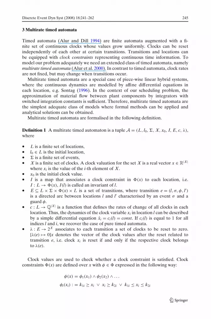
Fig. 2 Example automaton.The transition from location l2to l3 must take place at the firstpossible time instant.Switching between locationl1 and l2 can take place for2 ≤ x1 ≤ 4
3. a. σ ∈ �1 ∩ �2.e = ((l1, l2), σ, φ, (l′1, l′2)) ∈ E ⇐⇒ (l1, σ, φ1, l′1) ∈ E1 and (l2, σ, φ2, l′2) ∈ E2,φ = φ1 ∧ φ2.Then λ(e) = λ1(e1) ∪ λ2(e2).
b. σ ∈ �1 \ �2.e = ((l1, l2), σ, φ, (l′1, l2)) ∈ E ⇐⇒ (l1, σ, φ1, l′1) ∈ E1, φ = φ1.Then λ(e) = λ1(e1).
c. σ ∈ �2 \ �1.e = ((l1, l2), σ, φ, (l1, l′2)) ∈ E ⇐⇒ (l2, σ, φ2, l′2) ∈ E2, φ = φ2.Then λ(e) = λ2(e2).
We further introduce a set �∗ ⊂ � of forced events. Transitions labelled by forcedevents are called forced transitions, and they must occur at the first possible timeinstant, i.e. as soon as the clocks satisfy the guard φ. This time instant is not knownin all locations due to varying clock values at the previous switching time.
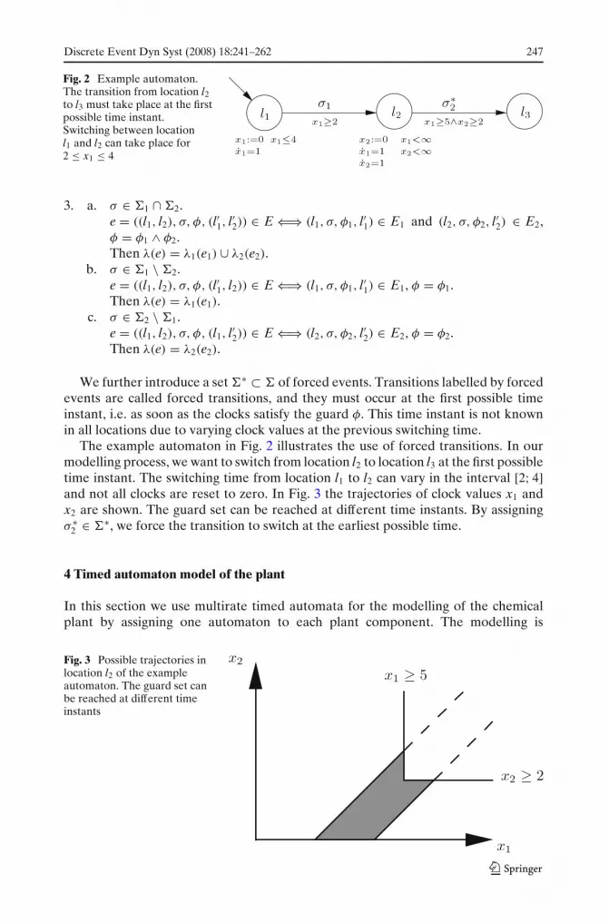
The example automaton in Fig. 2 illustrates the use of forced transitions. In ourmodelling process, we want to switch from location l2 to location l3 at the first possibletime instant. The switching time from location l1 to l2 can vary in the interval [2; 4]and not all clocks are reset to zero. In Fig. 3 the trajectories of clock values x1 andx2 are shown. The guard set can be reached at different time instants. By assigningσ ∗
2 ∈ �∗, we force the transition to switch at the earliest possible time.
4 Timed automaton model of the plant
In this section we use multirate timed automata for the modelling of the chemicalplant by assigning one automaton to each plant component. The modelling is
Fig. 3 Possible trajectories inlocation l2 of the exampleautomaton. The guard set canbe reached at different timeinstants

248 Discrete Event Dyn Syst (2008) 18:241–262
straightforward and common practice. Nevertheless, the modelling procedure isbriefly described for the sake of completeness, especially as we also apply forcedtransitions to reflect our problem properly. The plant consists of reactors, resourcesand an output tank. Reactors can be modelled by pure timed automata, i.e. clockrates do not change. In the output tank model the clock value represents the liquidlevel in the tank. Its rate can change depending on the in- and outflow, and a multiratetimed automaton is used for modelling. Resources can be in use or not and aredescribed by simple finite automata. Note that both standard untimed and timedautomata can be interpreted as special cases of multirate timed automata. Hence,the product is well defined, and the behaviour of the entire plant can be modelled bythe product of all automata resulting in a multirate timed automaton. In the followingwe explain the models of all types of components in detail.
4.1 Reactors
The first step is the modelling of the reactors using timed automata. Since theoperation sequence is identical in each reactor, they can be described in a uniformway, as shown in Fig. 4.
The operations processed in each reactor are represented by the locations woij andoij, which mean “wait before i-th operation starts in reactor j” and “i-th operationis active in reactor j.” The events Stoij and Eoij denote start and end of the i-thoperation in the j-th reactor, respectively. Fig. 4 is to be interpreted as follows: inlocation oij, the progress of time is measured by a clock modelled by x j = 1, and theclock is reset to zero when the transition from woij to oij takes place, i.e. when eventStoij occurs. We are only allowed to stay in the location oij if x j ≤ (d∗
i + di) holds(invariant). The event Eoij may only occur if x j ≥ (d∗
i − di) holds (guard). Hence,the transition between location oij to location wo(i+1) j has to happen when (d∗
i − di) ≤x j ≤ (d∗
i + di). The switching can take place at an arbitrary time instant within thisinterval, so that all possible disturbances are included in the model. In locationwoij, there are two possibilities: either invariant and guard of the outgoing transitionenforce an immediate switch to the next location (an example for this case is locationwo2 j in Fig. 4), or invariant and guard allow an arbitrarily long stay within the loca-tion (an example for this case is location wo3 j in Fig. 4). If a woij-location is of the for-
Fig. 4 A timed automaton model of reactor j
Discrete Event Dyn Syst (2008) 18:241–262 249
Busy BusyIdle Idle
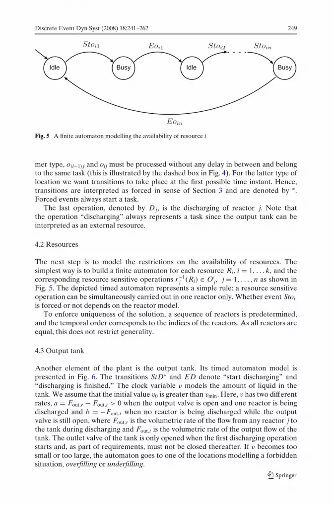
Fig. 5 A finite automaton modelling the availability of resource i
mer type, o(i−1) j and oij must be processed without any delay in between and belongto the same task (this is illustrated by the dashed box in Fig. 4). For the latter type oflocation we want transitions to take place at the first possible time instant. Hence,transitions are interpreted as forced in sense of Section 3 and are denoted by ∗.Forced events always start a task.
The last operation, denoted by Dj, is the discharging of reactor j. Note thatthe operation “discharging” always represents a task since the output tank can beinterpreted as an external resource.
4.2 Resources
The next step is to model the restrictions on the availability of resources. Thesimplest way is to build a finite automaton for each resource Ri, i = 1, . . . k, and thecorresponding resource sensitive operations r−1
j (Ri) ∈ O′j, j = 1, . . . , n as shown in
Fig. 5. The depicted timed automaton represents a simple rule: a resource sensitiveoperation can be simultaneously carried out in one reactor only. Whether event Stoi·is forced or not depends on the reactor model.
To enforce uniqueness of the solution, a sequence of reactors is predetermined,and the temporal order corresponds to the indices of the reactors. As all reactors areequal, this does not restrict generality.
4.3 Output tank
Another element of the plant is the output tank. Its timed automaton model ispresented in Fig. 6. The transitions StD∗ and ED denote “start discharging” and“discharging is finished.” The clock variable v models the amount of liquid in thetank. We assume that the initial value v0 is greater than vmin. Here, v has two differentrates, a = Fout,r − Fout,t > 0 when the output valve is open and one reactor is beingdischarged and b = −Fout,t when no reactor is being discharged while the outputvalve is still open, where Fout,r is the volumetric rate of the flow from any reactor j tothe tank during discharging and Fout,t is the volumetric rate of the output flow of thetank. The outlet valve of the tank is only opened when the first discharging operationstarts and, as part of requirements, must not be closed thereafter. If v becomes toosmall or too large, the automaton goes to one of the locations modelling a forbiddensituation, overfilling or underfilling.

250 Discrete Event Dyn Syst (2008) 18:241–262
Fig. 6 A multirate timedautomaton modelling theoutput tank
5 Control synthesis
In the controlled system, resources must be allocated in a nonconflicting way. Inaddition, we have safety specifications, the locations overfilling and underfilling mustbe rendered unreachable.
In the following we present control strategies to enforce the specifications. Theapproach combines feedforward scheduling strategies with hierarchical discreteevent feedback methods, which makes the overall scheduling problem less complexand more robust. Note that by adding a formal verification step, we can providea formal guarantee for the safety specifications to hold, even if the actual designprocess contains some heuristics (for the safety aspect).
The modular modelling framework allows us to apply a two-layer controllerstructure (Fig. 7). We first synthesise a controller which, by appropriate schedulingof reactor operations, guarantees nonconflicting resource allocation. This design stepincorporates off-line optimisation in on-line discrete event control. Other on-linestrategies can be added to solve further subproblems. E.g., in a second step, we designa controller for the output tank to guarantee safety.
Fig. 7 Two-layer controllerstructure
outputtank
resourceavailability
reactors
scheduling of reactor operations
scheduled plant
output flow control
plant model

Discrete Event Dyn Syst (2008) 18:241–262 251
5.1 Scheduling of reactor operations
The goal of the scheduling subproblem is to generate a nonblocking interaction ofreactor models (Fig. 4) and resource availability models (Fig. 5) for all possiblevariations in operation durations. We further want to minimise the duration tcbetween two discharging operations in the same reactor. For the case of varyingoperation durations, tc has to be minimised for the worst case, i.e. we want tominimise the maximal duration tc,max.
It is obvious that, in the uncontrolled case, the synchronous product of the nreactor models (Fig. 4) and the k resource availability models (Fig. 5) may give rise toblocking. This can happen in the following way: a resource, say Ri, is being allocatedby an operation oij in reactor j. At the same time, an operation o(i−1)( j−1) is finishedin reactor ( j − 1) and the succeeding operation oi( j−1) belonging to the same taskas o(i−1)( j−1) attempts to allocate Ri. In this situation, oi( j−1) must start immediatelyafter o(i−1)( j−1) has finished. This is clearly not possible as the corresponding resourceis still being used by reactor j.
It is intuitively possible to prevent blocking by appropriately delaying the startingtimes of tasks in the individual reactors. To determine the minimal necessary delays,we solve the corresponding scheduling problem in an off-line fashion and representthe result as timed automata which, when composed with reactor and resourceautomata, prevent blocking.
First, we give an algebraic formulation of the scheduling problem. We formulateall constraints to achieve a non-conflicting use of resources and meet the processrequirements. Operations have to be processed until completion which gives arelation between start times sij and finish times fij of operations oij:
f (ρ)
ij = s(ρ)
ij + d(ρ)
ij , i = 1, . . . , m, j = 1, . . . , n, ∀ρ ∈ N, (1)
where index ρ denotes the cycle number. Operations must be performed in a givensequence denoted by index i. The i-th operation must be completed before the(i + 1)-th operation in the same reactor can start:
s(ρ)
(i+1) j ≥ f (ρ)
ij , i = 1, . . . , m − 1, j = 1, . . . , n, (2)
s(ρ+1)
1 j ≥ f (ρ)
mj , j = 1, . . . , n, ∀ρ ∈ N. (3)
We further must take task constraints into account, namely time delays betweenoperations within a task must not occur:
sl(ρ)
(μ+1) j = f l(ρ)
μj , l = 1, . . . , p, j = 1, . . . , n, μ = 1, . . . |Klj| − 1, ∀ρ ∈ N, (4)
where the index l denotes the task and μ the temporal position of an operation withina task. Without loss of generality, we fix a reactor sequence to reduce degrees offreedom:
sl(ρ)
1( j+1) ≥ sl(ρ)
1 j , j = 1, . . . , n − 1, l = 1, . . . p, ∀ρ ∈ N, (5)
sl(ρ+1)
11 ≥ sl(ρ)
1n , l = 1, . . . , p, ∀ρ ∈ N. (6)
252 Discrete Event Dyn Syst (2008) 18:241–262
The following resource constraints exclude overlapping of two operations in differentreactors using the same resource Ri:
s(ρ)
i( j+1) ≥ f (ρ)
ij , j = 1, . . . , n − 1, i = 1, . . . , m, ∀oij ∈ O′j, oi( j+1) ∈ O′
j+1, (7)
s(ρ+1)
i1 ≥ f (ρ)
in , i = 1, . . . , m, ∀oi1 ∈ O′1, oin ∈ O′
n, ∀ρ ∈ N. (8)
This algebraic problem description corresponds to the timed automata repre-sentation set up previously. In particular, constraints 1 to 4 represent the “reactorautomata” (Fig. 4) and constraints 5 to 8 the “resource automata” (Fig. 5). Theequivalence can be shown by listing the temporal restrictions implied by the logicalstructure of the automata and their invariants and guards.
The inequality system 1 to 8 has to be solved for all possible variations of operationdurations while minimising tc,max. In this inequality system, the start times sl
1 j of tasksl are the only free parameters. We express the relation between these start times indifferent reactors by parameters wl : sl
1 j = sl1( j−1) + wl, j = 2, . . . , n.
For fixed processing times, the duration between two discharging operations inthe same reactor can be calculated by:
tc =
⎧⎪⎪⎨
⎪⎪⎩
n maxl
wl, form∑
i=1d∗
i < n maxl
wl
m∑
i=1d∗
i , otherwise.
(9)
Note that the minimum of tc is bounded from below bym∑
i=1d∗
i . If all parameters wl are
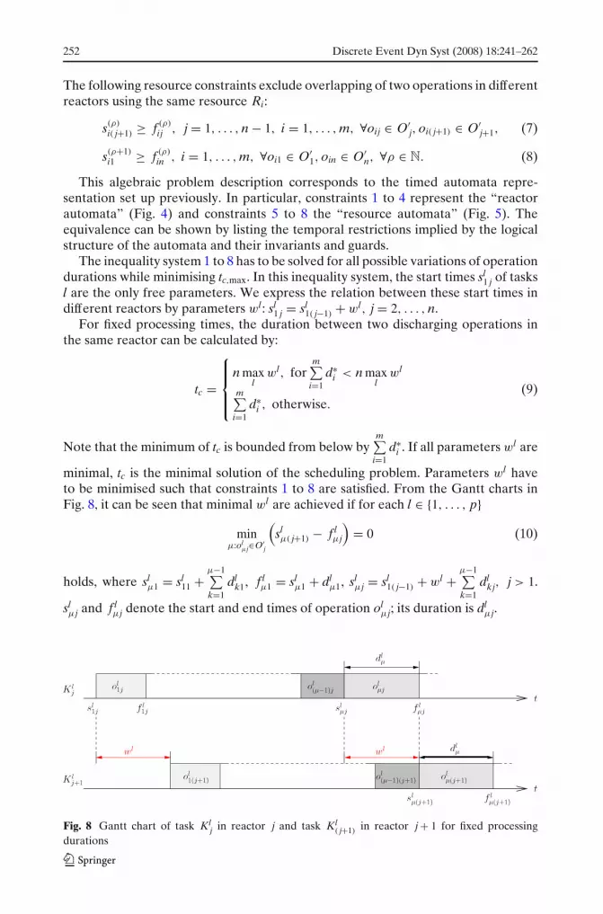
minimal, tc is the minimal solution of the scheduling problem. Parameters wl haveto be minimised such that constraints 1 to 8 are satisfied. From the Gantt charts inFig. 8, it can be seen that minimal wl are achieved if for each l ∈ {1, . . . , p}
minμ:ol
μj∈O′j
(slμ( j+1) − f l
μj
)= 0 (10)
holds, where slμ1 = sl
11 +μ−1∑
k=1dl
k1, f lμ1 = sl
μ1 + dlμ1, sl
μj = sl1( j−1) + wl +
μ−1∑
k=1dl
kj, j > 1.
slμj and f l
μj denote the start and end times of operation olμj; its duration is dl
μj.
Fig. 8 Gantt chart of task Klj in reactor j and task Kl
( j+1)in reactor j + 1 for fixed processing
durations

Discrete Event Dyn Syst (2008) 18:241–262 253
In the nominal case, the duration of each operation is known and fixed for allreactors: dl
μj = dlμ. Thus, the solution of the optimisation problem is wl = max
μdl
μ.
This is illustrated by the Gantt charts in Fig. 8. There, operation olμj is a resource
sensitive operation which satisfies condition 10. The start slμ( j+1) of the same task in
the subsequently used reactor is delayed by wl such that condition 10 holds. Hence,the first operation of a task is not allowed to start until the resource availability forall resource sensitive operations in the same task can be guaranteed. It can be seenthat the resulting wl are indeed minimal subject to constraints 1 to 8.
The situation becomes more complicated if the processing durations are onlyknown imprecisely, i.e., dl
μj ∈ [d∗i − d i; d∗
i + di], where the relation between i and μ
is explained in Section 2. Condition 10 then takes the form
minμ:ol
μj∈O′j
d lμj,d
lμ( j+1)∈[d∗
i −d i;d∗i +di]
(slμ( j+1) − f l
μj
)= 0. (11)
Thus, wl is calculated in a worst-case fashion and is therefore conservative. In Fig. 9the Gantt charts are depicted for this worst case situation. In reactor j, the processingdurations are smaller than in the nominal case while in reactor ( j + 1) operations lastlonger. This results in a larger wl than in the nominal case.
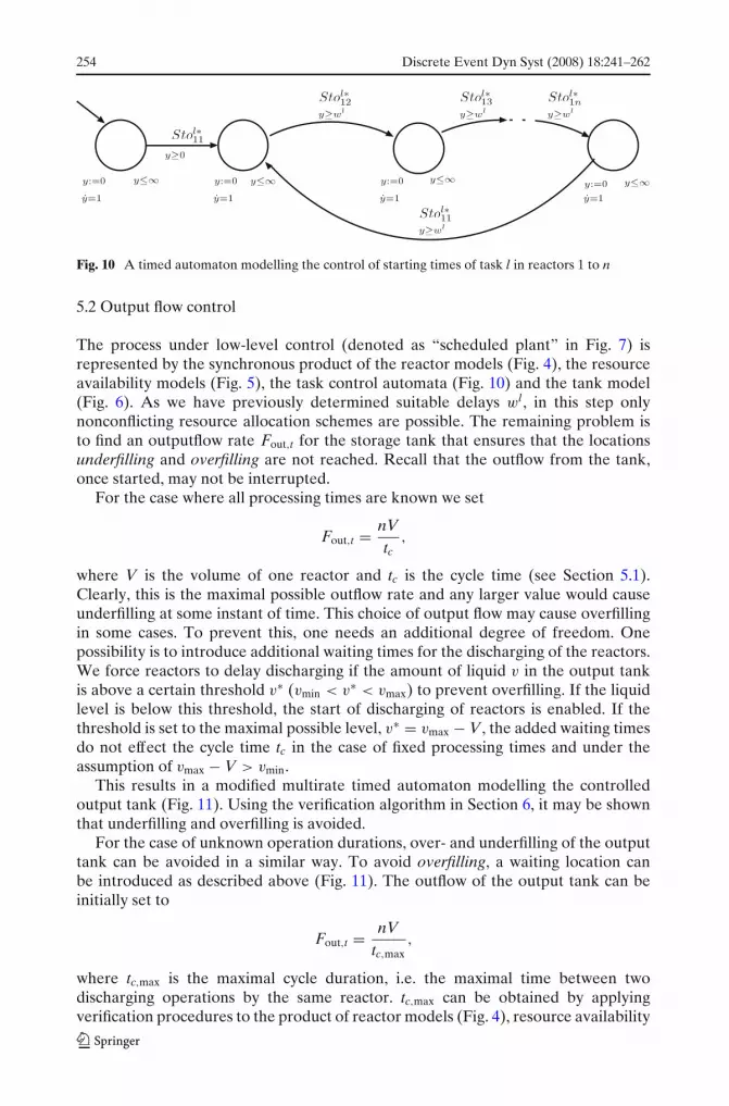
Hence, the solution of the scheduling problem is the computation of delays wl .Delaying task l by wl guarantees nonblocking while, in the nominal case, ensuringtime-optimal solutions. The insertion of delays can be easily translated into thetimed automata modelling framework. This is done by defining p timed automata,one for each task l, l = 1, . . . , p, as shown in Fig. 10. Note that events Stol∗
1 j in
Fig. 10 correspond to events Sto∗ij in the “reactor automata” if i =
l−1∑
q=1|Kq
j | + 1
(compare Section 2). When forming the product between these automata and theplant model, i.e. the “reactor automata” and the “resource automata,” the start oftasks in subsequently used reactors is suitably delayed.
Fig. 9 Gantt charts of task Klj in reactor j and task Kl
( j+1)in reactor ( j + 1) for imprecisely known
processing durations
254 Discrete Event Dyn Syst (2008) 18:241–262
Fig. 10 A timed automaton modelling the control of starting times of task l in reactors 1 to n
5.2 Output flow control
The process under low-level control (denoted as “scheduled plant” in Fig. 7) isrepresented by the synchronous product of the reactor models (Fig. 4), the resourceavailability models (Fig. 5), the task control automata (Fig. 10) and the tank model(Fig. 6). As we have previously determined suitable delays wl , in this step onlynonconflicting resource allocation schemes are possible. The remaining problem isto find an outputflow rate Fout,t for the storage tank that ensures that the locationsunderfilling and overfilling are not reached. Recall that the outflow from the tank,once started, may not be interrupted.
For the case where all processing times are known we set
Fout,t = nVtc
,
where V is the volume of one reactor and tc is the cycle time (see Section 5.1).Clearly, this is the maximal possible outflow rate and any larger value would causeunderfilling at some instant of time. This choice of output flow may cause overfillingin some cases. To prevent this, one needs an additional degree of freedom. Onepossibility is to introduce additional waiting times for the discharging of the reactors.We force reactors to delay discharging if the amount of liquid v in the output tankis above a certain threshold v∗ (vmin < v∗ < vmax) to prevent overfilling. If the liquidlevel is below this threshold, the start of discharging of reactors is enabled. If thethreshold is set to the maximal possible level, v∗ = vmax − V, the added waiting timesdo not effect the cycle time tc in the case of fixed processing times and under theassumption of vmax − V > vmin.
This results in a modified multirate timed automaton modelling the controlledoutput tank (Fig. 11). Using the verification algorithm in Section 6, it may be shownthat underfilling and overfilling is avoided.
For the case of unknown operation durations, over- and underfilling of the outputtank can be avoided in a similar way. To avoid overfilling, a waiting location canbe introduced as described above (Fig. 11). The outflow of the output tank can beinitially set to
Fout,t = nVtc,max
,
where tc,max is the maximal cycle duration, i.e. the maximal time between twodischarging operations by the same reactor. tc,max can be obtained by applyingverification procedures to the product of reactor models (Fig. 4), resource availability

Discrete Event Dyn Syst (2008) 18:241–262 255
Fig. 11 A modified timedautomaton modelling theoutput tank when overfilling isprevented by an additionalwaiting location
models (Fig. 5) and task control automata (Fig. 10). Applying the verificationalgorithm presented in Section 6 we check whether underfilling can be reached.If yes, Fout,t can be reduced iteratively. For highly uncertain processing times thesimultaneous avoidance of under- and overfilling may not be possible with a constantoutflow rate.
An alternative is to discretise the allowed range of the tank outflow Fout,t andswitch the output rate on-line between several values Fout,ti, Fout,ti < Fout,t(i+1), i =1, 2, . . . q, where the outflow rate Fout,ti is applied if the liquid level v is betweenthresholds vi−1 and vi (v0 < v1 < . . . < vq−1 < vq), with v0 = vmin and vq = vmax. Asin the method above, verification is required. If verification fails outflow rates orthresholds need to be adapted iteratively.
A modified output tank model with two different outflow rates is presented inFig. 12.
We have proposed strategies for the output tank control. Other algorithms e.g.the combination of waiting locations with switched outflow rates, can be modelled ina similar way as multirate timed automata. We have seen that even the rather simple
Fig. 12 A timed automaton modelling the controlled output tank with two different outflow rates
256 Discrete Event Dyn Syst (2008) 18:241–262
methods presented in this section require verification results. Hence, we focus onverification in the next section.
6 Verification
Our control approach in Section 5.2 contains some heuristics. Therefore, in particularfor large systems, it is essential to verify safety of the overall control systembehaviour. For more complex system structures than considered in the presentpaper, it might be necessary to integrate verification into an iterative controllersynthesis procedure. In this section, we present an algorithm for safety verificationof multirate timed automata. We show how to extend symbolic methods for “pure”timed automata to multirate timed automata. We also address some computationalissues to achieve a tractable problem and improve efficiency.
All possible temporal evolutions of (l, x) must meet a given safety requirement.The safety requirement is connected to a reachability problem, i.e. forbidden statesmust not be reached. In our system the locations underfilling and overfilling of theoutput tank automaton are forbidden.
One of the most important questions in the analysis of timed automata (and, ingeneral, of all hybrid systems) is the reachability of a given state or a set of states.We give a formal definition of reachability, introduce some symbolic operations andpropose an algorithm for reachability verification. The following definition is adaptedfrom Alur et al. (1995):
Definition 5 For a (multirate) timed automaton A with initial state (l0, x0), the state(l f , x f ) is reachable if there exists a sequence of discrete transitions e1, e2, . . . anddurations τ1, τ2 . . . such that
(l0, x0)τ1−→ (l0, x0)
e1−→ (l1, x1)τ2−→ . . . −→ (l f , x f ). (12)
Moreover, given a constraint φ ∈ �(x), we say that the configuration (l f , φ) isreachable if there exists a sequence of transitions and durations such that Eq. 12holds for some x f satisfying φ.
Numerical methods for reachability verification of timed automata are describedin Pettersson (1999), Bengtsson and Yi (2004), Bozga et al. (1998) and symbolicmethods are presented, for instance, in Asarin et al. (1995). Symbolic methods arebased on the partitioning of the state space of a timed automaton into symbolicstates which are represented by clock zones or regions. In the following we showhow to extend the symbolic framework to multirate timed automata and propose analgorithm for solving the reachability problem. Particular attention is paid to forcedtransitions.
A zone is a generalisation of a state of a (multirate) timed automaton. A zone Dis defined as a pair (lD, SD), where SD is a set of clock values, such that each x ∈ SD
satisfies the constraint I(lD). Zone D is said to be regular if SD is bounded and canbe represented as a set of clock constraints
SD = {x|Ax ≤ b , A ∈ Qn×k, b ∈ Q
n, k = |X|}.A lifting operation is introduced as a generalisation of a continuous transition (see
Def. 3).
Discrete Event Dyn Syst (2008) 18:241–262 257
Definition 6 A lifting operation S↑D(τ ) is defined as
S↑D(τ ) = {x | x = x + τc(l), (l, x) ∈ D} ∩ I(l)(X ).
Furthermore, it can be generalised to an untimed lifting operation S↑D =
∞⋃
τ=0S↑
D(τ ).
Based on this, one can define a generalised (symbolic) transition relationBengtsson and Yi (2004).
Definition 7 The symbolic transition relation, denoted by �, is defined by thefollowing rule:
(l, S) � (l′, [λ(e) → 0](S↑ ∩ φ(X ))), if ∃e = (l, σ, φ, l′) ∈ E \ E∗.
In our case, the above transition relation must be extended by a new transition rulefor forced transitions e ∈ E∗. A forced transition must take place as soon as clockssatisfy the guard φ. Thus, the corresponding transition rule can be defined as
(l, S)∗� (l′, [λ(e) → 0](S↑ ∩ φ(X ))), if ∃e = (l, σ, φ, l′) ∈ E∗,
where φ(X ) is a part of the boundary φ(X ) characterised by φ(X ) = {x ∈ φ(X )|xi ≤xi∀x ∈ φ(X ) for at least one i}.
Inspired by Bengtsson and Yi (2004), the algorithm below checks whether thegiven automaton can reach zone (l f , S f ) starting from (l0, S0).
Algorithm Reachability analysis.
New := {l0, S0}, Checked := ∅While New = ∅
Next := ∅For each (l, S) ∈ New
For each l′ ∈ Post(l)If (l, σ, φ, l′) ∈ E\E∗
(l′, S′) = (l′, [λ(e) → 0](S↑ ∩ φ(X )))
Else(l′, S′) = (l′, [λ(e) → 0](S↑ ∩ φ(X )))
End IfNext := Next
⋃(l′, S′)
End ForEnd ForIf Next ∩ (l f , S f ) = ∅
Type ("zone (l f , S f ) is reachable")Stop
End IfChecked := Checked
⋃(Next \New)
New := Next \CheckedEnd WhileType ("zone (l f , S f ) is not reachable")

258 Discrete Event Dyn Syst (2008) 18:241–262
The computational details are out of the scope of this paper. Nevertheless, a fewshort remarks seem appropriate.
There are only few operations that need to be performed cyclically during thereachability computation. First, we need to compute the result of the untimed liftingoperation S↑
D and find - if it exists - its intersection with the guard φ(X ). Thiscan be done using the quantifier elimination algorithm (see Anai and Weispfennig2001 and references within). As a result of quantifier elimination one gets a setof equations that describes all possible clock values that can be reached via therespective transition. Obviously, an empty set means that this transition cannot takeplace and, therefore, the successor location cannot be reached via this transition.
For a discussion of implementation issues of the remaining set-theoretic opera-tions we refer to Avis et al. (2002), Halbwachs et al. (1994), Halbwachs et al. (2006),Goodman and O’Rourke (1997).
Obviously, multirate timed automata form a subclass of piecewise linear hybridsystems. Therefore, in principle, methods and tools for this class of systems could beapplied. However, regarding computational efficiency, it seems wise to exploit theadditional structure embodied in multirate timed automata.
7 Example
We now consider a specific example described in detail in Simeonova et al. (2005).The plant consists of two reactors. In each reactor the following sequence ofoperations is performed: filling (d∗
1 = 0.17 h), heating (d∗2 = 0.45 h), maintaining
temperature (d∗3 = 3.44 h), cooling (d∗
4 = 0.92 h) and discharging (d∗5 = 0.17 h). The
operations filling, heating and cooling are resource-sensitive. The set of operationshas been partitioned into three tasks: K1
j ={filling}, K2j ={heating, maintaining temper-
ature, cooling} and K3j ={discharging}, j = 1, 2. The time for heating is only known
imprecisely: d2 ∈ [d∗2 − d2, d∗
2 + d2] where d2 = d2 = 0.13 h. The volumes of bothreactors are 27 m3. The minimal and maximal volume of liquid in the tank is vmin = 0and vmax = 50 m3, respectively.
We applied the method presented in the previous sections to obtain a solution thatallocates resources in a nonconflicting way, performs a worst-case minimisation ofcycle duration and guarantees safety for all possible variations of parameters. Usingthe first method from Section 5.2, the maximal admissible constant tank outflow is
j=1
j=20 1 2 3 4 5 6 7 8 9 10 11 12
T,h
Filling HeatingMaintainingtemperature
Cooling Discharging
Fig. 13 Resulting schedule for d2 j = d∗2 + d2, j = 1, 2
Discrete Event Dyn Syst (2008) 18:241–262 259
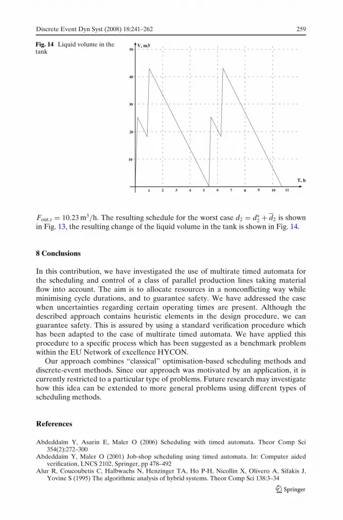
Fig. 14 Liquid volume in thetank
10
20
30
40
50
1 2 3 4 5 6 7 8 9 10 11
T, h
V, m3
Fout,t = 10.23 m3/h. The resulting schedule for the worst case d2 = d∗2 + d2 is shown
in Fig. 13, the resulting change of the liquid volume in the tank is shown in Fig. 14.
8 Conclusions
In this contribution, we have investigated the use of multirate timed automata forthe scheduling and control of a class of parallel production lines taking materialflow into account. The aim is to allocate resources in a nonconflicting way whileminimising cycle durations, and to guarantee safety. We have addressed the casewhen uncertainties regarding certain operating times are present. Although thedescribed approach contains heuristic elements in the design procedure, we canguarantee safety. This is assured by using a standard verification procedure whichhas been adapted to the case of multirate timed automata. We have applied thisprocedure to a specific process which has been suggested as a benchmark problemwithin the EU Network of excellence HYCON.
Our approach combines “classical” optimisation-based scheduling methods anddiscrete-event methods. Since our approach was motivated by an application, it iscurrently restricted to a particular type of problems. Future research may investigatehow this idea can be extended to more general problems using different types ofscheduling methods.
References
Abdeddaïm Y, Asarin E, Maler O (2006) Scheduling with timed automata. Theor Comp Sci354(2):272–300
Abdeddaïm Y, Maler O (2001) Job-shop scheduling using timed automata. In: Computer aidedverification, LNCS 2102, Springer, pp 478–492
Alur R, Coucoubetis C, Halbwachs N, Henzinger TA, Ho P-H, Nicollin X, Olivero A, Sifakis J,Yovine S (1995) The algorithmic analysis of hybrid systems. Theor Comp Sci 138:3–34
260 Discrete Event Dyn Syst (2008) 18:241–262
Alur R, Dill DL (1994) A theory of timed automata. Theor Comp Sci 126:183–235Alur R, Henzinger TA, Lafferriere G, Pappas GJ (2000) Discrete abstractions of hybrid systems.
Proc IEEE 88(7):971–984Anai H, Weispfennig V (2001) Reach set computations using real quantifier elimination. In: Proceed-
ings of the 4th International Workshop on Hybrid Systems: Computation and Control, number2034 in LNCS, Springer, pp 63–76
Asarin E, Maler O, Pnueli A (1995) Symbolic controller synthesis for discrete and timed systems. In:Hybrid Systems II, LNCS 999, Springer, pp 1–20
Avis D, Fukuda K, Picozzi S (2002) On canonical representations of convex polyhedra. MathematicalSoftware, World Scientific, pp 351–360
Bengtsson J, Yi W (2004) Timed automata: Semantics, algorithms and tools. In: Reisig W, RozenbergG (eds) Lecture Notes on Concurrency and Petri Nets, LNCS 3098. Springer
Bozga M, Daws C, Maler O, Olivero A, Tripakis S, Yovine S (1998) Kronos: a model-checkingtool for real-time systems. In: Hu AJ, Vardi MY (eds) Computer Aided Verification, CAV ’98,Vancouver, Canada, LNCS 1427, Springer, pp 546–550
Goodman JE, O’Rourke J (eds) (1997) Handbook of discrete and computational geometry. CRCPress
Gromov D, Geist S, Raisch J (2006) Timed discrete control of a parallel production line withcontinuous output. In: Proceedings of the 2nd IFAC Conference on Analysis and Design ofHybrid Systems, Alghero, Italy, pp 205–210
Halbwachs N, Merchat D, Gonnord L (2006) Some ways to reduce the space dimension in polyhedracomputations. Form Methods Syst Des 29(1):79–95
Halbwachs N, Proy Y-E, Raymond P (1994) Verification of linear hybrid systems by means of convexapproximations. In: International Symposium on Static Analysis, SAS’94
Méndez CA, Cerdá J, Grossmann IE, Harjunkkoski I, Fahl M (2006) State-of-the-art review ofoptimization methods for short-term scheduling of batch processes. Comput Chem Eng 30:913–946
Niebert P, Yovine S (2000) Computing optimal operation schemes for chemical plants in multi-batchmode. In: HSCC, pp 338–351
Panek S, Stursberg O, Engell S (2006) Efficient synthesis of production schedules by optimization oftimed automata. Control Eng Pract (14):1183–1197
Pettersson P (1999) Modelling and verification of real-time systems using timed Automata: theoryand Practice. PhD thesis, Uppsala University
Schilling G, Pantelides CC (1999) Optimal periodic scheduling of multipurpose plants. ComputChem Eng 23:635–655
Simeonova I, Warichet F, Bastin G, Dochain D, Pochet Y (2005) On-line scheduling of chemicalplants with parallel production lines and shared resources: a feedback implementation. In:Proceedings IMACS World Congress, Paris
Sontag ED (1996) Interconnected automata and linear systems: a theoretical framework in discretetime. In: Alur R, Henzinger TA, Sontag ED (eds) Hybrid systems III: verification and control(Lecture notes in computer science) Springer, pp 436–448
Wu D, Ierapetritou M (2004) Cyclic short-term scheduling of multiproduct batch plants usingcontinuous-time representation. Comput Chem Eng (28):2271–2286
Discrete Event Dyn Syst (2008) 18:241–262 261
Stephanie Geist is currently a Ph.D. student in the Control Systems group at Technische UniversitätBerlin, Germany. She received her Diploma in automatic control from Otto-von-GuerickeUniversity in Magdeburg, Germany, in 2004. Her work is in the area of hybrid control systems andhierarchical control. She is participating in the International Curriculum Option of Doctoral Studiesin Hybrid Control for Complex, Distributed and Heterogeneous Embedded Systems and is an activemember of the European Network of Excellence project HYCON.
Dmitry Gromov received his Diploma in automatic control from the Belorusian State Universityof Informatics and Radioelectronics, Minsk, Belarus, in 1996. Currently, he is working towardshis PhD degree at Technische Universität Berlin. His research interests include supervisory andoptimal control of hybrid systems as well as hierarchical control and process control applications.He is participating in the International Curriculum Option of Doctoral Studies in Hybrid Controlfor Complex, Distributed and Heterogeneous Embedded Systems and the European Network ofExcellence HYCON.
262 Discrete Event Dyn Syst (2008) 18:241–262
Jörg Raisch is a professor at Technische Universität Berlin, where he heads the Control SystemsGroup within the Department of Electrical Engineering and Computer Science. He is also headof the Systems and Control Theory Group at the Max Planck Institute for Dynamics of ComplexTechnical Systems in Magdeburg, Germany. He studied Engineering Cybernetics and ControlSystems at Stuttgart University and UMIST, Manchester. He got his Ph.D and “Habilitation”, bothfrom Stuttgart University, in 1991 and 1998, respectively. From 1991–1993 he was a postdoc in theSystems Control Group at the University of Toronto. From 2000–2006 he was a professor at theOtto-von-Guericke University Magdeburg, where he headed the automatic control lab. His researchinterests are in hybrid systems and hierarchical control and include biomedical control and chemicalprocess control applications.