compositional verification of timed components using pvs
TRANSCRIPT
Compositional Verification of Timed Components usingPVS∗
Marcel KyasChristian-Albrechts-Universitat zu Kiel, Germany
Jozef HoomanEmbedded Systems Institute & Radboud University Nijmegen, The Netherlands
Abstract: We present a general framework to support the compositional verificationof timed systems using the interactive theorem prover PVS. The framework is based ontimed traces that are an abstraction of the timed semantics of flat UML state machines.We define a compositional proof rule for parallel composition and prove its soundnessin PVS. After composition, a hiding rule can be applied to hide internal events. Thegeneral theories have been applied to parts of the Medium Altitude ReconnaissanceSystem (MARS) as deployed in the F-16 aircraft of the Royal Netherlands Air-Force.
1 Introduction
In recent years, UML [Obj04] has been applied to the development of reactive safety-critical systems, in which the quality of the developed software is a key factor. Within theOmega project we have developed a method for the correct development of real-time em-bedded systems using a subset of UML, which consists of state machines, class diagrams,and object diagrams. In this paper we present a general framework supporting compo-sitional verification of such designs using the interactive theorem prover PVS [ORS92,ORSvH95]. The framework is based on timed traces, which are abstractions of the timedsemantics of UML state machines [vdZH06]. The focus is on the level of components andtheir interface specifications, without knowing their implementation [dR85, HdR85].
Our specifications are logical formulae that express the desired properties of a system or itscomponents using predicates on timed traces. To formalise intermediate stages during thetop-down design of a system, we have devised a mixed formalism where specifications andprogramming constructs can be mixed freely. In this paper, we restrict ourselves to parallelcomposition and hiding. This is inspired by similar work on untimed systems [Old85,Zwi89] and related to work on timed systems [Hoo98].
We apply our general theories to a part of the Medium Altitude Reconnaissance System
∗This work has been supported by EU-project IST-2001-33522 OMEGA “Correct Development of Real-TimeEmbedded Systems.” For more information, see http://www-omega.imag.fr/.

(MARS) as deployed by the Royal Netherlands Air Force on the F-16 aircraft [Ome05].The system employs two cameras to capture high-resolution images. It counteracts imagequality degradation caused by the aircraft’s forward motion using a compensating motionof the film during its exposure. The control values for the forward motion compensationof the film speed and the frame rate are being computed in real-time, based on the cur-rent aircraft altitude, ground speed, and some additional parameters. The system is alsoresponsible for producing the frame annotation, containing time and the aircraft’s currentposition, which must be synchronised with the film motion. Here, we focus on the data-bus manager. It receives messages from sensors measuring the altitude and the position ofthe aircraft and tries to identify whether the sensors have broken down and — if they have— whether they have recovered.
In the OMEGA project, several formal techniques have been applied to the MARS casestudy. Live Sequence Charts (LSCs) [DH01] have been used to capture the requirements.Non-timed, functional properties of the MARS system have been verified using the model-checking tool UVE [STMW04]. Timed model checking has been applied by means ofIFx, an extension of the IF toolbox [BGO+04]. The approaches based on model-checkingprovide simulation and automated verification, but are limited to finite state systems.
To allow general verification of unbounded, infinite state systems, we have used the PVStool, a general purpose theorem prover which is freely available [PVS]. PVS has a pow-erful specification language, based on higher-order typed logic. Specifications can beorganised as hierarchies of parameterised theories, which may contain, e.g., declarations,definitions, axioms, and theorems. The PVS proof engine can be used to prove theoremswhich have been stated in the theories. To prove a particular goal, the user invokes proofcommands which should simplify the goal until it can be proved automatically by PVS.
The first verification experiments with the original UML-model of the MARS system re-vealed that global, non-compositional verification is difficult and limited to small systems.To be able to apply compositional verification, the MARS system has been redesigned bymeans of a few well-defined components. The focus of this paper is on the specificationsthat have been used for the compositional verification of this redesign using PVS.
In the next section we describe the semantics of our formal framework. Section 3 intro-duces compositional proof rules. Section 4 describes the overall behaviour of our casestudy. Section 5 describes the decomposition of this overall specification into suitablecomponents. Section 6 contains concluding remarks.
2 Semantics
Specifications are based on assertions which are predicates on traces θ consisting of obser-vations o. For each observation we observe the event that is occurring, written E(o), andthe time at which it occurs, written T (o). Time is defined to be a non-negative real anddelays are assumed to be positive. The special event ε represents either that time elapsesor that some hidden event is occurring. We use θi to denote the i-th observation of trace θ.Traces have to satisfy the following properties in order to be well-formed:

1. Time is monotone: ∀i, j : i ≤ j → T (θi) ≤ T (θj)
2. Time progresses, i.e., is non-Zeno: ∀i, δ : ∃j : i ≤ j ∧ T (θi) + δ ≤ T (θj)
3. Proper events are instantaneous: ∀i : E(θi) 6= ε → T (θi) = T (θi+1)
The projection of a trace θ on a set of events Eset is defined as:
θ ↓ Eset def= λk :
{θk, if E(θk) ∈ Esetε, otherwise
A component is specified by an assertion and a signature which is a set of events Esetwhich can be observed by the component. Usually this concerns the receiving and thesending of messages. The assertion specifies the behaviour of the component, a set oftraces, formalised by a predicate Θ on traces θ over its signature. Hence, a componentC is defined by the pair (Eset ,Θ), where the behaviour respects the interface, i.e., ∀θ :Θ(θ) → θ ↓ Eset = θ.
We define parallel composition of components C1 = (E1,Θ1) and C2 = (E2,Θ2) as
C1 ‖ C2def= (E1 ∪ E2, {θ | θ ↓ E1 ∈ Θ1 ∧ θ ↓ E2 ∈ Θ2 ∧ θ ↓ (E1 ∪ E2) = θ})
That is, the projection of any trace of the parallel composition on the signature of oneof the components yields a trace of this component. Observe that this implies that thecomponents synchronise on their common events. Moreover, a trace of the compositionshould not include any new events outside the joint signature, as in [dRea01, Section 7.4].
For a component C = (E,Θ) and a set of events E′ the hiding operator C − E′ removesthe events in E′ from the signature of C. It is formally defined by
C − E′ def= (E \ E′, {θ | ∃θ′ ∈ Θ : θ = θ′ ↓ (E \ E′)}).We define a few suitable abbreviations.
• E(θi) = e states that the event e occurs at position i in the trace θ
• Never(e, i, j)(θ) def= ∀k : i ≤ k ∧ k ≤ j → E(θk) 6= e asserts that the event e doesnot occur between positions i and j in the trace θ
• Never(e)(θ) def= ∀k : E(θk) 6= e asserts that e never occurs in trace θ
• AfterWithin(e, i, δ)(θ) def= ∃j : j ≥ i ∧E(θj) = e ∧ T (θj)− T (θi) ≤ δ states thatthe event e occurs at some position j after i which is no later that δ time units from i
Because we aim at a mixed framework, in which specifications and programming con-structs can be mixed freely, a specification is also considered to be a component. Hencespecification S = (E,Θ) is identified with the component (E, {θ | θ ↓ E = θ ∧Θ(θ)}).Component C1 = (E1,Θ1) refines component C2 = (E2,Θ2), written C1 =⇒ C2, ifE1 = E2∧∀θ : Θ1(θ) → Θ2(θ). The refinement relation is a partial order on componentsand specifications.

3 Compositional Proof Rules
Next we derive a number of compositional proof rules. Their correctness is checked inPVS based on the semantic definitions and the definition of specifications.We start with aconsequence rule, which allows the weakening of assertions in specifications.
Let C1 = (E1,Θ1) and C2 = (E2,Θ2) be two specifications. Then(E1 = E2 ∧ (∀θ : Θ1(θ) → Θ2(θ))) → (C1 =⇒ C2)
To define a sound rule for parallel composition, we first show that the validity of an asser-tion Θ only depends on its signature. This is specified using the following predicate:
depends(Θ, E) def⇐⇒ ∀θ, θ′ : Θ(θ) ∧ θ ↓ E = θ′ ↓ E → Θ(θ′)Then we can establish ∀E : depends(Θ, E) ↔ (∀θ : Θ(θ) ↔ Θ(θ ↓ E)). Using thisstatement we can prove the soundness of the following parallel composition rule:
(depends(Θ1, E1) ∧ depends(Θ2, E2)) →((E1,Θ1) ‖ (E2,Θ2) =⇒ (E1 ∪ E2,Θ1 ∧Θ2))
To be able to use refinement in a context, we derive a monotonicity rule:
((C1 =⇒ C2) ∧ (C3 =⇒ C4)) → ((C1 ‖ C3) =⇒ (C2 ‖ C4))
Similarly, we prove a compositional rule and a monotonicity rule for the hiding operator.
depends(Θ, E1 \ E2) → (((E1,Θ)− E2) =⇒ (E1 \ E2,Θ))
(C1 =⇒ C2) → ((C1 − E) =⇒ (C2 − E))
4 The MARS Example
We consider only a small part of the MARS example, namely the data bus manager. Thispart serves as an illustration on how to apply the presented techniques to a timed system.Figure 1 shows the architecture of the data bus manager.
Message Receiver
ControllerMonitor
−curOk: Boolean−prevOK: Boolean
DatabusController
NavigationDataSourceAltitudeDataSource
Figure 1: Architecture of data bus manager

The data sources altitude data source and navigation data source send data to a messagereceiver. If the data sources function correctly, they send data with period P and jitterJ < P
2 , as depicted in Figure 2; data should be sent in the grey periods.
t
P
J
Figure 2: Data with period P and jitter J
First, we specify correct data sources, using S = {1, 2} as an abstract representation ofthe two data sources. Let ds represent the data items sent by source s, where s ranges overS, and D = {ds | s ∈ S} denotes the total set of data items sent by both sources.
For any data source s its behaviour is specified by the assertion DSs,1(θ) ∧ DSs,2(θ) onits traces of observations θ. Assertion DSs,1 specifies that each occurrence of an event ds
is within the period specified by the jitter. DSs,2 specifies that at most one such messageis sent during this period.
DSs,1(θ)def⇐⇒ ∀i : E(θi) = ds → ∃n : nP − J ≤ T (θi) ∧ T (θi) ≤ nP + J
DSs,2(θ)def⇐⇒ ∀i, j : E(θi) = ds ∧ E(θj) = ds →
i = j ∨ P − 2J ≤ |T (θi)− T (θj)|Consequently, a data source will not send data outside of the assigned time frame and willalso not send more than one data sample during this time frame.
Next we formalise the global specification of the MARS system. If a data source failsto send a data item for K consecutive times, then the system shall indicate this error bysending signal err . The system is said to have recovered if N consecutive data messageshave been received from each source. In the original MARS system K = 3 and N = 2.
The occurrence of N consecutive events e between i and j is specified by the predicateocc(e,N, i, j), which is defined as follows:
occ(e,N, i, j)(θ) def⇐⇒ N = 0 ∨∃f : |dom(f)| = N ∧ f(0) = i ∧
f(|dom(f)| − 1) = j ∧ (∀k : k ≤ |dom(f)| − 1 → E(θf(k)) = e) ∧(∀k : k < |dom(f)| − 1 → f(k) < f(k + 1) ∧P − J < T (θf(k+1))− T (θf(k)) ∧ T (θf(k+1))− T (θf(k)) < P + J)
This implies that there exists a strictly monotonically increasing sequence f of length Nof indexes starting at i and ending at j such that at each position in this sequence the evente occurs and that these events occur P ± J time-units apart.
To express that K data items have been missed we define:
TimeOut(e, t, i, j)(θ) def⇐⇒ Never(e, i, j) ∧ T (θj)− T (θi) ≥ t

which states that event e has not occurred for at least t time units between positions i andj in trace θ.
Observe that a data source s is in an error state at position i in the trace θ if it has not sentdata for at least L
def= KP + 2J time units at position j ≤ i and that it has not recovereduntil position i. This is expressed by the following assertion:
Error(d, i)(θ) def⇐⇒ ∃k, j : j ≤ i ∧ TimeOut(d, L, k, j)(θ) ∧(∀m : j < m ∧m ≤ i → ¬∃l : occ(d, N, l, m)(θ))
The validity of an error signal is specified by assertion TDS1, where ∆err represents thedelay needed to react to the occurrence of an error.
TDS1(θ)def⇐⇒ ∀i, j : i < j ∧ (∃s : TimeOut(ds, L, i, j)(θ)) ∧
(∀s : ¬Error(ds, j)(θ)) → AfterWithin(err , j,∆err )(θ)
The integrity of the error signal err is specified by:
TDS2(θ)def⇐⇒ ∀j : E(θj) = err →
∃i, k : i < k ∧ k < j ∧ (∃s : TimeOut(ds, L, i, k)(θ)) ∧(∀s : ¬Error(ds, k)(θ)) ∧Never(err , k, j − 1)(θ)
The system recovers from an error when all data sources have been sending N consecutivemessages. This recovery is indicated by sending a ok signal. The next predicate specifiesthat all sources have indeed sent N consecutive data messages.
Recover(D, i, j) def⇐⇒ ∃f, g : i = mind∈D f(d) ∧ j = maxd∈D g(d) ∧(∀d, d′ : |T (θf(d))− T (θf(d′))| ≤ 2J) ∧(∀d, d′ : |T (θg(d))− T (θg(d′))| ≤ 2J) ∧(∀d : occ(d, N, f(d), g(d)))
This predicate states that there exist two functions f and g from events to positions suchthat i is the smallest value produced by f , j is the largest value produced by g, the valuesin the range of f are at most 2J time units apart, as are the values in the range of g suchthat we have N occurrences of d between f(d) and g(d). Using this predicate, we candefine the validity of the ok signal, using delay ∆ok to model the reaction time needed torecover.
TDS3(θ)def⇐⇒ ∀i, j : i < j ∧ Recover(D, i, j)(θ) ∧
(∃s : Error(ds, j)(θ)) → AfterWithin(ok , j,∆ok )(θ)
The integrity of the ok signal is specified by:
TDS4(θ)def⇐⇒ ∀j : E(θj) = ok →
∃i, k : i < k ∧ k < j ∧ (∃s : Error(ds, i)(θ)) ∧Recover(D, i, k)(θ) ∧Never(ok , k, j − 1)(θ)
Finally, we specify the behaviour of the global system by TDS:
TDS(θ) def⇐⇒∧
1≤i≤4 TDSi(θ)
5 Decomposition of the MARS example
In this section we decompose the MARS system in a few components, such that we canshow by compositional deductive verification that the composition of these componentssatisfies the global specification TDS as presented in the previous section.
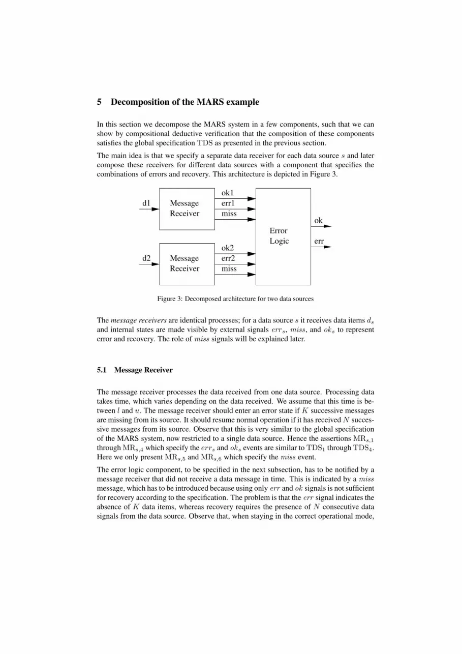
The main idea is that we specify a separate data receiver for each data source s and latercompose these receivers for different data sources with a component that specifies thecombinations of errors and recovery. This architecture is depicted in Figure 3.
ReceiverMessage
ReceiverMessage
LogicError
ok1err1miss
ok2err2miss
err
ok
d2
d1
Figure 3: Decomposed architecture for two data sources
The message receivers are identical processes; for a data source s it receives data items ds
and internal states are made visible by external signals errs, miss , and oks to representerror and recovery. The role of miss signals will be explained later.
5.1 Message Receiver
The message receiver processes the data received from one data source. Processing datatakes time, which varies depending on the data received. We assume that this time is be-tween l and u. The message receiver should enter an error state if K successive messagesare missing from its source. It should resume normal operation if it has received N succes-sive messages from its source. Observe that this is very similar to the global specificationof the MARS system, now restricted to a single data source. Hence the assertions MRs,1
through MRs,4 which specify the errs and oks events are similar to TDS1 through TDS4.Here we only present MRs,5 and MRs,6 which specify the miss event.
The error logic component, to be specified in the next subsection, has to be notified by amessage receiver that did not receive a data message in time. This is indicated by a missmessage, which has to be introduced because using only err and ok signals is not sufficientfor recovery according to the specification. The problem is that the err signal indicates theabsence of K data items, whereas recovery requires the presence of N consecutive datasignals from the data source. Observe that, when staying in the correct operational mode,

a few missing data items are allowed, but no missing data item is allowed when trying torecover.
Observe that we can use a single miss event for all message receivers. We do not need aseparate event for each message receiver, because in order to recover, all message receivershave to receive N consecutive data messages. The miss signal indicates that there existsa component which missed a data message during this period. The error logic componentneed not know which message receiver missed the data message.
A message receiver sends a miss message to the error logic whenever a time-out for a datamessage occurs and it is not in an error state. If the message receiver is already in an errorstate, it signals N consecutive data messages using an ok message. Therefore, it is notnecessary to send miss signals in this case. Sending a miss signal may be delayed by atmost ∆MR
miss time units.
MRs,5(θ)def⇐⇒ ∀j : TimeOut(ds, P + 2J, i, j)(θ) ∧ ¬Error(ds, j)(θ) →
AfterWithin(miss, j,∆MRmiss)(θ)
Note that if the Kth data item is missed at j, the Error(ds, j)(θ) predicate is true andsignal miss is not emitted. Instead, by MRs,3, an errs signal is sent, i.e., not both a misssignal and an errs signal are sent.
The integrity of a miss event is specified by MRs,6.
MRs,6(θ)def⇐⇒ ∀j : E(θj) = miss →
∃i, k : i < k ∧ k < j∧ ¬Error(ds, i)(θ) ∧TimeOut(ds, P + 2J, i, k)(θ) ∧Never(miss, k, j − 1)(θ)
From N missing miss signals one can conclude that the data source s has received Nconsecutive data messages:
Lemma 1. For any s, i, j, if TimeOut(miss, NP + 2J, i, j) then occ(ds, N, i, j)
More importantly, the timeout of the miss signal implies that all message receivers havereceived N consecutive data messages.
Corollary 2. For all i, j, if TimeOut(miss, NP + 2J, i, j), then Recover(D, i, j)
Finally, we specify a message receiver for a source s as MRs(θ)def⇐⇒
∧1≤i≤6 MRs,i(θ).
5.2 Error Logic
The error logic component accepts errs and oks signals from each data source s, as wellas a signal miss indicating that there exists a data source s that has not received data fromits source during this cycle. The error logic will emit an err signal if it detects an errorin the system and an ok signal if the system recovers after an error. The behaviour of theerror logic is specified in the state machine of Figure 4.
State AllOk indicates that the system operates normally. When receiving an errs signal

Err2Err1
err1/t:=0
err1/t:=0
err2/t:=0
err2/t:=0
Miss1 Miss2
Errors
Miss
Wait
AllOk
[t >= N*P+2*J]
[t >= N*P+2*J]
miss/t := 0[t >= N*P+2*J]
miss/t := 0
err2/ err1/
err1/!err
err2/!err
miss/t:=0
miss/t:=0
miss/t:=0miss/t:=0
miss/t:=0
ok1/
ok2/ ok1/
ok2/
ok1/!ok
ok2/!ok[t >= N*P+2*J]!ok
ok1/ok2/
Figure 4: State Machine of the error logic component
in this state, for some s ∈ {1, 2}, signal err is sent and state Errs is entered. Recoveryfrom this state occurs when an oks signal is received. But if an error signal is received forthe other source, state Errors is entered, indicating that the system has to recover from anerror in both data sources.
As long as the system is in the AllOk state it ignores all miss signals. If the system is in anerror state, i.e., one of err1, err2, or Errors, and it receives a miss signal, the error logichas to wait for a new time-out of the miss signal and the required number of ok signals inorder to return to normal operation, which is represented by the states Miss1, Miss2, Miss,and Wait. The system measures the time elapsed since the latest reception of a miss signalusing the clock t. Consequently, it resets t whenever it receives a miss signal or a errs
signal.
State Wait is entered whenever one of the Misss states has been left after receiving thecorresponding oks signal, and the error logic itself has to emit an ok signal to confirm thatthe system has recovered from the error condition. Observe that we have to wait until theend of the current period in order to assert that during this time neither message receiversends an error signal. After a time-out of the miss signal, state Wait is left, AllOk isentered, and an ok signal is emitted.
As an example, we give a scenario to show that state Wait is reachable. Suppose an err1
signal is received in state AllOk, leading to state Err1. During the next period a misssignal is received from message receiver 2. This causes a state change to Miss1, indicatingthat it has to receive an ok1 signal and, moreover, has to wait until message receiver 2received N consecutive data messages. Observe that in this situation message receiver

1 only has to receive N − 1 data messages. Assuming that both message receivers willreceive their data messages, message receiver 1 sends its ok1 signal after N − 1 periods,after which state Wait is entered. Next the error logic component has to wait anotherperiod in order to make sure that message receiver 2 has received its N th data message,after which it may signal recovery.
In order to specify the error logic component in a declarative way, we first formalisewhether an error of data source s has been detected and when the system is in state AllOk.
Error(i, s)(θ) def⇐⇒ ∃m : m ≤ i ∧ E(θm) = errs ∧Never(oks,m + 1, i)(θ)
AllOk(i)(θ) def⇐⇒ ∀s : ¬Error(i, s)(θ)
The validity and integrity of an err signal indicating error is specified as follows, using amaximal delay of ∆EL
err time units.
EL1(θ)def⇐⇒ ∀i : AllOk(i)(θ) ∧ (∃s : E(θi+1) = errs) →
AfterWithin(err , i + 1,∆ELerr )
EL2(θ)def⇐⇒ ∀j : E(θj) = err →
∃i : i < j ∧AllOk(i)(θ) ∧ (∃s : E(θi+1) = errs)∧Never(err , i + 2, j − 1)(θ)
The next predicate states that a data source s recovers from an error:
Recover(i, s)(θ) def⇐⇒ ∀i : Error(i− 1, s)(θ) ∧ E(θi) = oks
Next, using a maximal delay of ∆ELok , the validity and integrity of an ok signal is specified.
EL3(θ)def⇐⇒ ∀i : (∃s : Recover(i, s)(θ)) ∧ (∀s : ¬Error(i, s))∧
(∃k : TimeOut(miss, NP+2J, k, i)(θ)) →AfterWithin(ok , i,∆ELok )
EL4(θ)def⇐⇒ ∀j : E(θi) = ok →
∃i : i < j ∧ (∃s : Recover(i, s)(θ)) ∧ (∀s : ¬Error(i, s))∧Never(ok , i+1, j−1)∧(∃k : TimeOut(miss, NP +2J, k, i)(θ))
The error logic is specified by the assertion: EL(θ) def⇐⇒∧
1≤i≤4 ELi(θ)
6 Conclusions
We have presented a compositional framework for the compositional verification of high-level real-time components which communicate by means of events. Compositional proofrules for parallel composition and hiding have been proved sound in PVS. In this way,we can use deductive verification in PVS to prove the correctness of a decomposition of asystem into a number of communicating components. Next, the components can be imple-mented independently using UML, according to their specification, and the correctness ofthe implementation with respect to the interface specification may be established by meansof other techniques, such as model checking.

The framework has been applied to the MARS case study, which has been supplied bythe Netherlands National Aerospace Laboratory in the form of UML models. The spec-ifications presented here are the result of a long and arduous path leading to consistentspecifications of the parts and the full formal proof in PVS. In general, interactive verifi-cation of UML models is very complex because we have to deal with many features si-multaneously, such as timing, synchronous operation calls, asynchronous signals, threadsof control, and hierarchical state machines. Hence, compositionality and abstraction areessential to improve scalability. Verifying the MARS case study indeed shows that deduc-tive verification is more suitable for the correctness proofs of high-level decompositions,to eventually obtain relatively small components that are suitable for model checking.
Since the original UML model of MARS was monolithic, a redesign of the original sys-tem was necessary to enable the application of compositional techniques and increase ourunderstanding of the model. Interestingly, this led to a design that is more flexible, e.g.,for changing the error logic, and more easily extensible, e.g., to more data sources, thanthe original model.
Errors in the decomposition of the MARS system have been found using model checking(by means of the IF validation environment [BFG+00] and UPPAAL [LPY95]) and by thefact that no proof could be found for the original specification. One of these errors wasthat we did not include a miss signal, which is required to correctly observe recovery inthe error logic component. Otherwise, the system recovered in circumstances where theglobal specification did not allow this.
Observe that the compositional approach requires substantial additional effort to obtainappropriate specifications for the components. Finding suitable specifications is difficult.Hence, it is advisable to start with finite high-level components and to simulate and tomodel-check these as much as possible. Apply interactive verification only when sufficientconfidence has been obtained. Finally, it is good to realise that interactive verification isquite time consuming and requires detailed knowledge of the tool.
Acknowledgements We would like to thank all partners of the OMEGA project for manyfruitful discussions on the MARS case study.
References
[BFG+00] Marius Bozga, Jean-Claude Fernandez, Lucian Ghirvu, Susanne Graf, Jean-PierreKrimm, and Laurent Mounier. IF: A Validation Environment for Timed AsynchronousSystems. In E. Allen Emerson and A. Prasad Sistla, editors, Computer Aided Verifica-tion ’00, volume 1855 of LNCS. Springer-Verlag, 2000.
[BGO+04] Marius Bozga, Susanne Graf, Ileana Ober, Iulian Ober, and Joseph Sifakis. The IFtoolset. In SFM-04:RT 4th Int. School on Formal Methods for the Design of Com-puter, Communication and Software Systems: Real Time, pages 237–267. LNCS 3185,Springer-Verlag, 2004.
[dBdRR85] Jaco W. de Bakker, Willem-Paul de Roever, and Grzegorz Rozenberg, editors. CurrentTrends in Concurrency, volume 224 of LNCS. Springer-Verlag, 1985.

[DH01] Werner Damm and David Harel. LSCs: Breathing Life into Message Sequence Charts.Formal Methods in System Design, 19(1):45–80, 2001.
[dR85] Willem-Paul de Roever. The Quest for Compositionality — a survey of assertion-based proof systems for concurrent programs, Part 1: Concurrency based on sharedvariables. In Proc. IFIP Working Conference 1985: The Role of Abstract Models inComputer Science. North-Holland, 1985.
[dRea01] Willem-Paul de Roever et al. Concurrency Verification. Cambridge University Press,2001.
[HdR85] Jozef Hooman and Willem-Paul de Roever. The Quest goes on: A survey of ProofSystems for Partial Correctness of CSP. In de Bakker et al. [dBdRR85].
[Hoo98] Jozef Hooman. Compositional Verification of Real-Time Applications. In Willem-Paul de Roever, Hans Langmaack, and Amir Pnueli, editors, Compositionality: TheSignificant Difference, volume 1536 of LNCS. Springer-Verlag, 1998.
[LPY95] Kim Larsen, Paul Pettersson, and Wang Yi. Model-Checking for Real-Time Systems.In Horst Reichel, editor, Proc. Fundamentals of Computation Theory, volume 965 ofLNCS. Springer-Verlag, 1995.
[Obj04] Object Management Group. UML 2.0 Superstructure Specification, October 2004.http://www.omg.org/cgi-bin/doc?ptc/2004-10-02.
[Old85] Ernst-Rudiger Olderog. Process Theory: Semantics, specifications and verification. Inde Bakker et al. [dBdRR85].
[Ome05] Omega Consortium. Medium Altitude Reconnaissance System. Webpage at http://www-omega.imag.fr/cs/MARS/MARS.php, 2005.
[ORS92] Sam Owre, John M. Rushby, and Natarajan Shankar. PVS: A Prototype VerificationSystem. In Deepak Kapur, editor, Automated Deduction – CADE-11, volume 607 ofLNAI. Springer-Verlag, 1992.
[ORSvH95] Sam Owre, John M. Rushby, Natarajan Shankar, and Friedrich von Henke. Formalverification for fault-tolerant architectures: Prolegomena to the design of PVS. IEEETransactions on Software, 21(2):107–125, 1995.
[PVS] PVS. http://pvs.csl.sri.com/.
[STMW04] Ingo Schinz, Tobe Toben, Christian Mrugalla, and Bernd Westphal. The RhapsodyUML Verification Environment. In Proc. 2nd IEEE Int. Conf. on Software Engineeringand Formal Methods (SEFM2004), pages 174–183. IEEE Computer Society Press,2004.
[vdZH06] Mark van der Zwaag and Jozef Hooman. A Semantics of Communicating ReactiveObjects with Timing. Journal on Software Tools for Technology Transfer, 2006.
[Zwi89] Job Zwiers. Compositionality, Concurrency and Partial Correctness, volume 321 ofLNCS. Springer-Verlag, 1989.