pvs series variable volume piston pumps
TRANSCRIPT

insert the return section of the drain piping into the hydraulic operating fluid. Also, observe the values in the following table to limit the drain back pressure to 14 psi.
•Management of Hydraulic Operating FluidUse good-quality hydraulic operating fluid,and use within a kinematic viscosity range of 20 to 200 centistokes during operation. Use an R&O type and antiwear hydraulic fluid of ISO-VG32 to 68.The optimum kinematic viscosity during
290 to 507290 to 1015435 to 2030435 to 3045
290 to 507290 to 1015435 to 2030435 to 3045
290 to 507290 to 1015435 to 2030435 to 3045
290 to 507290 to 1015435 to 2030435 to 3045
290 to 507290 to 1015435 to 2030435 to 3045
0
M
*
*
Dischargeport
Suctionport
Drainport
Energy-saving Type with Drastically Reduced LossA NACHI-proprietary semi-circular barrel swash plate that receives pressure on its surface ensures a stable discharge volume at all times. This eliminates excess discharge volume, and enables the
Features
A
Piston Pumps
effective use of power corresponding to the load cycle. This "energy-saving type" conserves energy, reduces power loss, and helps to reduce hydraulic costs.
Silent Type That Demonstrates Its Power QuietlyProprietary low-noise mechanisms are incorporated on the shoe, swash plate, valve plate, and other locations to ensure silent operation. In particular, a semi-circu-lar barrel swash plate stabilizes operation characteristics to ensure silent operation.
•Handling•Cautions during Pump Installation and PipingUse flexible couplings for connecting thepump shaft to the drive shaft, and preventa radial or thrust load from being appliedon the pump shaft.For centering of the pump shaft, limit theeccentricity between the drive shaft andhydraulic pump shaft to .002 in, andkeep the angle error within 1°.Set the clamping length of couplings andhydraulic pump shafts so that it is withinat least 2/3 or more of the coupling width.Use a sufficiently rigid pump mountingbase.Set the pressure on the pump suctionside to 4.3 or more (suction portflow velocity within 6 ft/sec).Raise part of the drain piping to abovethe topmost part of the pump body, and
1
2
3
1
PVS Series Variable .48 to 2.74 cu in/revVolume Piston Pumps 3045 psi
☼ Design No. 30 is applied on PVS-0B to make the pump more compact and lighter, and reduce noise.☼ Production of PVS-3B has been discontinued. Use PZS-3B.☼ Pressure adjustment 3 type has been added to PVS-1B-22 and PVS-2B-45. (Design No. 20 is applied only on PVS-2B-45*3)
PVS Series Variable Volume Piston Pump
Specifications
Model No.
ItemPVS-0BPVS-1B PVS-2B
Pipe joint size 3/8"or more
1/2"or more
Pipe I.D
Pipe length 39” 39”
Volumein³/rev
(cm³/rev)
Discharge volume at no-load gpm Pressure adjustment range psi
Permittedpeak pressure
psi
Rotating speed min-1 Masslbs
1000min -1 1200min -1 1500min -1 1800min -1 Min. Max.
3625
3625
3625
3625
3625
500
500
500
500
500
2000
2000
2000
2000
2000
Note: Direction of rotation is clockwise when viewed from the shaft end.
Model No.
PVS-0B-8*0-E30123
PVS-1B-16*0-(*)-E13123
PVS-1B-22*0-(*)-E13123
PVS-2B-35*0-(*)-E13123
PVS-2B-45*0-(*)-E1312
3 -(*)-E20
.18 - .48(8.0)
.3 - 1.0(16.5)
.42 - 1.34(22.0)
.48 - 2.1(35.0)
.67 - 2.74(45.0)
2.1
4.4
5.8
9.2
11.9
2.5
5.2
7.0
11.1
14.3
3.2
6.5
8.7
13.9
17.9
3.8
7.8
10.5
16.6
21.5
17
23
23
51
51
operation is 20 to 50 centistokes.The operating temperature range is 40 to190º F. When the oil temperature at startup is 40º F or less, warm up the hydraulic pump by low-pressure, low-operation speed operation until the oil temperature reaches 40°F.Provide a suction strainer with a filteringgrade of about 100μm (150 mesh). Besure to provide a return line filter of grade10μm or less on the return line to the tank. (When the hydraulic pump is used at a high pressure of 2000 psi or more, we recommend providing a filter of 10μm or less.Manage the hydraulic operating fluid sothat contamination is maintained at classNAS10 or lower.Use hydraulic operating fluid within anoperating ambient temperature of 32 to140º F. (continued on following page)
4
5
6
2
3
4
5
3/8" 1/2"
A 3

A 4
A
Piston Pumps
• Caution at Startup NACHI-proprietary Before you start pump operation, fill thepump body with clean hydraulic operatingfluid via the lubrication port.
An unload is required when the motor isstarted under condition WYE.Delta Start. Consult your agent regarding the circuit.Make sure that the pump operates in thedirection of rotation the same as thatindicated by the arrow on the pump body.
Air entering the pump or pipes maycause noise or vibration. At startup, setthe pump discharge side to a no-loadstate, and operate the pump in the inching mode to release any air in the pump or pipes.Provide an air bleed valve in circuitswhere it is difficult to release air at startup.• How to Set Pressure and DischargeVolumeThe default pump discharge volume isset to "maximum" and default discharge pressure is set to "minimum". Change the discharge volume and discharge pressure settings according to your particular operating conditions.
Model No. Injection amount cu in
PVS-0B-8 13
PVS-1B-16, 22 18
PVS-2B-35, 45 39
1
2
3
4
5
CW
CCW
Pressureadjustment range
Dis
char
gevo
lum
eD
isch
arge
volu
me
Dis
char
ge v
olum
ead
just
men
t ran
ge
CW
CCW
Pressure
Pressure
[Pressure adjustment]Turning the pressureadjusting screw CW increases the pressure.[Discharge volumeadjustment]Turning the flowrate adjusting screw CW decreases thedischarge volume.Note:∙ For details regarding the relationship between flow rate adjustment length l and pump capacity q, see the tables provided in the installation dimension drawings for each of the pumps.∙ Firmly tighten the lock nuts after you have finished adjustments.Note:• Variable control mechanism Standard TypeN* Pressure compensation type (manual mode)Option typeP* Pressure compensation type (remote control mode)R Load Sense
N*Q* 2-pressure, 2-flow rate control
Solenoid cutoff control
2-pressure control
2-pressure, 2-flow rate control w/ solenoid cutoff
2-cutoff control
• * : Pressure adjustment range 0 : 286 - 500 1 : 286 - 1000 2 : 429 - 2000 3 : 429 - 3000
• : Applicable to solenoid specifications A, SA : SA-G01S : SS-G01 1 : 100V 50/60Hz 2 : 200V 50/60Hz 3 : DC12V 4 : DC24V
R*
W*
RQ*
C*
ASASAS
AS
*
*
*
*
***
Design No. 30: PVS-0B 12: PVS-1B, PVS-2B (BSPT piping) E13: PVS-1B, PVS-2B (SAE piping) E20: PVS-2B -45N3
Explanation of Model No.
122N16B1– – – –PVS *( )
Auxiliary Symbol None: Side port type Z: Axial port type
Pressure Adjustment Range [Note] Reference
Variable Control Mechanism [Note] Reference
Max. Pump Capacity (cm³/rev) Nominal 8, 16, 22, 35, 45
Mounting Method B: Mounting flange type A: Mounting foot type
Pump Size 0,1,2
PVS Series Variable Piston Pump
■ R, load sense available for all PVS models.■ NQ, RS, WS, RQS and CS types are not available for the PVS-0B-8. ■ NQ, RQS and CS types are not available for the PVS-1B- -Z and PVS-2B- -Z.16
223545
N2: 429-2000psiDis
char
ge v
olum
eD
isch
arge
vol
ume
Dis
char
ge v
olum
eD
isch
arge
vol
ume
Dis
char
ge v
olum
eD
isch
arge
vol
ume
Dis
char
ge v
olum
e
[Example 1]N*: Pressure compensation type (manual mode)PVS-1B-16N2
P2: 429-2000psi[Example 2]P*: Pressure compensation type (remote control mode)PVS-1B-16P2
P2: 429-2000psi
sol"ON"
sol"OFF"
[Example 4]R*S*: Solenoid cutoff controlPVS-1B-16R2S2Solenoid specifications120V 50/60HzSS-G01
W2: 429-2000psi
sol"ON"
sol"OFF"
[Example 5]W*S*: 2-pressure controlPVS-1B-16W2S1Solenoid specifications120V 50/60HzSS-G01
N2: 429-2000psi
Q1: 290-1000psi
Discharge pressure
[Example 3]N*Q *: 2-pressure, 2-flow rate controlPVS-1B-16N2Q1
R2: 429-2000psi
sol"ON"
sol"OFF"Discharge pressure
Discharge pressure
Discharge pressure
Discharge pressure
Discharge pressure
[Example 6]RQ *S*: 2-pressure, 2-flow rate control w/ solenoid cutoffPVS-1B-16RQ2S1Solenoid specifications120V 50/60HzSS-G01
C2: 429-2000psi
sol"ON"
sol"OFF"Discharge pressure
[Example 7]C *S*: 2-cutoff controlPVS-1B-16C2S2Solenoid specifications120V 50/60HzSS-G01

Variable Control Mechanisms
A
Piston Pumps
Stan
dard
type
Opt
ion
type
Symbol External View Characteristics Hydraulic Circuit Explanation
N
NACH
I
Drain portPressureadjusting screwFlow rate
adjusting screw
Dis
char
ge v
olum
e
Discharge pressure
0
M
*
*
Dischargeport
Suctionport
Drainport
P
NACH
I
Drain portFlow rateadjusting screw
Pilot port Differential pressureadjusting screw(adjustment forbidden)
Dis
char
ge v
olum
e
Discharge pressure
0
M*
*
PilotportDischargeport
Suctionport
Drainport
NQ
NACH
I
P1 pressure adjusting screw
q1 flow rate adjusting screwq2 flow rateadjusting screw
P2 pressureadjusting screwDrain port
q2
q1
P1
P2
Dis
char
ge v
olum
e
Discharge pressure
0
MN *
*
Discharge port
Suctionport
Drainport
RS(RA)
SOL b
NACH
I
Drain portPressureadjusting screw(at solenoid ON)
Flow rateadjusting screw
SOL"OFF"
SOL"ON"
Dis
char
ge v
olum
e
Discharge pressure
0
M*
*
Discharge port
Suctionport
Drainport
WS(WA)
NACHI
Drain port
Pressureadjusting screw(at solenoid OFF)
Flow rateadjusting screw
Pressureadjusting screw(at solenoid ON)
SOL b
SOL"OFF"
P1 P2
SOL"ON"
Dis
char
ge v
olum
e
Discharge pressure
0M*
*
Discharge port
Suctionport
Drainport
RQS(RQA)
SOL b
NACH
I
Drain port
P1 pressure adjusting screw
P2 pressureadjusting screw(at solenoid ON)
q1 flow rateadjusting screw
q2 flow rateadjusting screw
P2
q1
q2 P1
SOL OFF
SOL ON
Dis
char
ge v
olum
e
Discharge pressure
*
*0
MN
Discharge port
Suctionport
Drainport
CS(CA) N
ACHI
Drain port
P2 pressure adjusting screw
q1 flow rate adjusting screwq2 flow rateadjusting screw
Differential pressureadjusting screw(adjustment forbidden)
q1
q2
P1 P2SOL OFF
SOL ON
Dis
char
ge v
olum
e
Discharge pressure
* *0
MN
Discharge port
Suctionport
Drainport
Note 1: Many other variable control mechanism are also available in addition to those in the above table. Please consult your agent for details.Note 2: We recommend ZR-T02-*-5895* as the remote control valve. For details, consult your agent. Prevent the pipe volume up to the remote control valve from falling below 10 cu in.
Pressure compensation type(manual system)When the discharge pressurereaches the preset volumeset by the pressure compen-sator, the discharge volume isautomatically reduced to holdthe pressure at the set pressure.
Pressure compensation type(remote control mode)This mode demonstrates thesame characteristics as themanual mode.The discharge pressure canbe adjusted by external pilotpressure. The discharge volumecan be adjusted manually.
2-pressure, 2-flow rate control typeThe discharge volume changes in two stages by the pump's built-in sequence valve. This allows conventional high/ low pressure control to be performed on a single pump unit, and save energy in the hydraulic circuit.
Solenoid cutoff control typeA solenoid valve for unload isintegrated into the pressurecompensation type to minimizeenergy loss when pump outputis not required. Only a slightamount of heat is generated.
2-pressure control typeTwo pressure compensationtypes can be obtained byswitching the solenoid valveON/OFF. Two types of outputcontrol are possible with theactuator set to a constantspeed.
2-pressure, 2-flow rate control type w/ solenoid cutoffThe discharge volume can bechanged in two stages by thesequencer valve and solenoidvalve for unload mounted onthe pump, and unloading ispossible when pressure oil isnot required.
2-cutoff control typeTwo types of pressure - flowrate characteristics can beobtained by the solenoid valveand cylinder mounted on thepump.
NACH
I
Drain portFlow rateadjusting screw
Load sense Differential pressureadjusting screw(adjustment forbidden)
Dis
char
ge v
olum
e
Discharge pressure
0
M*
*
PilotportDischargeport
Suctionport
Drainport
Load sense typeThis mode demonstrates thesame characteristics as themanual mode.The discharge pressure canbe adjusted by external pilotpressure. The discharge volumecan be adjusted manually.Note 2)
R
A 5

A 6
A
Piston Pumps
Pressure Compensation Type Manual Mode: Standard Type
2 Bolt SAE A MountPVS-0B-8N*-30
Installation Dimension Drawing
Cross-Sectional Drawing
Pressure Compensation Type
Suction portSAE 3/4
Lubrication port29
4911
47
127
77
3
110130
R46
106.453.2
Discharge portSAE 1/2
19.0
521
.2 82.60 0 –0.2
5 –0.0
36–0
.071
0–0.012
142
78
525.442.5
–0.0
21
Key width 4.76
Pressure compensatorMIN
Drain portSAE 3/8
Lock nut
Discharge port
Lock nut
164.5(MAX)
(flow rateadjustmentlength)18 614
49.5214( MAX)
510
Flow rateadjusting screw
Pressureadjusting screw
SAE 1/2
11
149.5127.5
.39
.61
.48
.36
.24
.12
.18
.59.19
PVS-0B-8N*-30
cu in
/rev
PVS-0B-8N*-30
Pum
p ca
paci
ty q
cu
in/r
ev
Flow rate adjustment length in.
Set a flow rate adjustment length withinthe above range. Oil will leak if the pumpis operated below the adjustment rangelower limit.
Part No. Part Name Part No. Part Name Part No. Part Name
123456789
1011121314
BodyCaseShaftCylinder barrelValve platePistonShoeShoe holderBarrel holderSwash plateThrust bushSpring holderGasketSpring C
1516171819202122232425262728
Spring S Control pistonGuide pinParallel keyRetainerNeedleBall bearingNeedle bearingOil sealSnap ringSnap ringSnap ringO-ringO-ring
29303132
33
34353637383940
Parallel pinSpring pinHexagon socket head boltCross-recessed countersunkhead screwHexagon socket setscrewHexagon nutHexagon plugMetal plugNameplateLubrication port plateCAUTION plateRivet
Parts marked by an asterisk "*"are not available on the market.Consult your agent.
PartNo. Part Name Q'ty
PVS-0B-8Size Remarks
13 Packing 1 PSC46-100000 3 Bond23 Oil seal 1 TCV-254511 N.O.K27 O-ring 1 1B-P9 JIS B 240128 O-ring 1 1B-P11 JIS B 2401
*
Typical characteristics at hydraulic operating fluid kinematic viscosity of 32 centistokes
Discharge volume Q
Volume efficiency ηv
Overall efficiency η
Input Lin
1800min–1
1800min–1
1500min–1
1500min–1
200010000
5060
4.03.73.43.2
8
5.4
2.7
0
708090
100
Discharge pressure P psi
General Performance
3000
Input Lin
Drain volume DR
Discharge volume Q1800min–1
1800min–1
1500min–1
1500min–1
00
0.5
1.1
6
4
2
0
3.7
3.2
Discharge pressure P psi
Pressure - DischargeVolume Characteristics
1800min–1
1500min–1 1500/1800min–1
1500min–1
0
2.7
2.0
1.3
0.7
0
Full cutoff pressure psi
Axial Input at Full Cutoff
050
60
80
70
Discharge pressure P psi
At full cutoff
Measurement position: 1m rear of pump
Noise Characteristics
Q=3.8r /minQ=3.2r /minQ=2.6r /minQ=2.1r /minQ=1.6r /min
00
1.3
2.7
9.4
8.0
6.7
5.4
4.0
Discharge pressure P psi
Axial Input
1800min–1
Effic
ienc
yη,ηv
% Dis
char
ge v
olum
eQ
gpm
Inpu
t Lin
hp
Inpu
t Lin
hp
Dis
char
ge v
olum
eQ
gpm
Dra
in v
olum
eD
R gp
m
Axia
l Inp
ut h
p
Axia
l inp
ut a
t ful
l cut
off h
p
Noi
se le
vel d
B(A)
20001000 3000 20001000 3000
20001000 300020001000 3000
Seal Kit Part No. PSS-100000

A
Piston Pumps
Installation Dimension Drawing
PVS-1B- 16N*-(Z)-E1322SAE A Mount
(side port type)
(Axial Port Type)
Parts marked by an asterisk "*" are not available on the market.Consult your agent.
List of Sealing Parts (Kit Model Number PSS-101000-2A)
Part No. Part Name Part No. Part Name
123456789
101112131415161718192021
BodyCaseShaftCylinder barrelValve platePistonShoeShoe holderBarrel holderSwash plateThrust bushSeal holderGasketSpring CSpring SControl pistonNeedleKeyNutRetainerPlug
222324252627282930313233
3435363738394041
Ball bearingNeedle bearingOil sealSnap ringSnap ringSnap ringO-ringO-ringO-ringPinHexagon socket head boltCross-recessed coun-tersunk head screwHexagon socket set screwMetal plugNameplateCAUTION plateSpring holderLubrication port plateRivetGuide pin
Part No. Name Q'ty Size Remarks13 Gasket 1 PS46-101000 Nihon Gasket24 Oil seal 1 TCN-254511 N.O.K28 O-ring 1 1B-G55 JIS B 240129 O-ring 1 1B-P9 JIS B 240130 O-ring 1 1B-P14 JIS B 2401
Lubrication port
Discharge portCode 61 - 3/4
Suction portCode 61 - 1
106.4
130
52
117388
42
124
8213
73
NACH
I
4-M10X16
24
12.5158.5
22±0.2
47.5±
0.2
181.5
55237(MAX)
Flow rateadjustment length
19.0
521
.2φ
Flow rateadjusting screw
82.6
–0.0
21
–0.2
5
φ
Key width4.76 0
–0.012
525.4
649.5
43
0 0
–0.0
36–0
.071
(MIN)Drain portSAE 3/8
77.523r
φ
Pressureadjusting screw
NACH
I
SAE 3/8
4.76 0–0.012
4-M10X164-M10X16
Code 61 - 3/4Code 61 - 1
525.4
12.5
649.577.5
55
237(MAX)
42.5
23(MIN)
183.5 106.4130
52
1173
88
42
8213
73
3030110
52.4
±0.2
47.5
±0.2
120 r
19.0
521
.2
82.6
0 –0.0
210 –0
.25
φ
φ
–0.0
36–0
.071
22±0.226.2±0.2
(suction port24 mm dia.)
(discharge port24 mm dia.)
Flow rateadjusting screw
Flow rateadjustment length Drain port Pressure
adjusting screw
Key width
Pressure compensator Lubrication port
.19 .39 .59
.61
1.2
Flow rate adjustment length l in
PVS-1B-16N*-12
PVS-1B-22N*-12
0
1.8
.78
1.0
1.3
.42
.30Flow rate adjustment range
Flow rate adjustment range
Relationship between flow rate adjustmentlength (l) and pump capacity (q)
Pum
p ca
paci
ty q
cu
in/r
ev
*
Cross-Sectional Drawing
Set a flow rate adjustment length within the above range. Oil will leak if the pump is operated below the adjustment range lower limit.
A 7

20001000 3000
20001000 3000
A 8
A
Piston Pumps
Performance Curves Typical characteristics at hydraulic operating fluid kinematic viscosity of 32 centistokes
PVS-1B-16N*-(Z)-E13
Discharge volume Q Dischargevolume Q
Volume efficiency ηv
Overall efficiency η
Input Lin
1800min–1
1800min–1
1500min–1
1500min–1
200010000
5040
60
7.97.4
16.1
10.713.4
5.32.6
8.0
0
708090
100
Discharge pressure P psi
General Performance
3000
Input Lin
Drain volume DR
1800min–1
1800min–1
1500min–1
1500min–1
00
.5
1.1
16.1
10.7
5.3
0
7.47.9
Discharge pressure P psi
Pressure - DischargeVolume Characteristics
1800min–1
1500min–1
1800min–1
1500min–1
0
2.7
2.0
1.3
0.7
0
Full cutoff pressure psi
Axial Input at Full Cutoff
0
60
80
70
Discharge pressure P psi
At full cutoff
Full cutoff pressureFull cutoff pressure
1000 psi500 psi
Tank capacity 10 gal
Measurement position: 1m rear of pump
Revolution speed 1800 min–1
Noise Characteristics
Q=7.9gpm
Q=6.6gpm
Q=5.3gpm
Q=3.9gpm
Q=2.6gpm
00
18.7
16.1
13.4
10.7
8.0
5.3
2.6
Discharge pressure P psi
Axial Input
640 1 3 5 72
32
86
68
50
Time Hr
Oil Temperature Rise CharacteristicsPVS-1B-16N1-12
8
Effic
ienc
yη,ηv
%
Dis
char
ge v
olum
eQ
gpm
Inpu
t Lin
hp
Inpu
t Lin
hp
Axia
l inp
ut h
p
Dra
in v
olum
eD
R gp
mD
isch
arge
vol
ume
Q gp
m
Axia
l inp
ut a
t ful
l cut
off h
p
Noi
se le
vel d
B(A)
Tem
pera
ture
diff
eren
ce º
F
Performance Curves
Full cutoff pressureFull cutoff pressure
1000 psi500 psi
Tank capacity 16 gal
Revolution speed 1800 min–1
640 1 3 5 72Time Hr
8
Tem
pera
ture
diff
eren
ce º
F
Curves Typical characteristics at hydraulic operating fluid kinematic viscosity of 32 centistokes
PVS-1B-22N*-(Z)-E13
0 0
5.4
10.7
16.11800min–
1
1500min–1
Input Lin
6050
708090
100
10.69.37.96.6
21.419.0
13.4
8.0
2.7
Discharge pressure P psi
Overall efficiency η
1800min–1
1500min–1
General PerformanceDischargevolume Q
Dis
char
ge v
olum
eQ
gpm
Inpu
t Lin
hp
Effic
ienc
yη,ηv
%
Volume efficiency ηv
0
5.3
10.7
16.1
Input Lin
1800min–1
1500min–1
10.6
7.9
21.4
1800min–1
1500min–1
Pressure - Flow RateCharacteristics
0
.5
1.1
Drain volume DR
Discharge pressure P psi
Dis
char
ge v
olum
eQ
gpm
Dra
in v
olum
eD
R gp
m
Discharge volume Q
Inpu
t Lin
hp
1500min–11800min–1
0
2.7
0
0.7
1.3
2.0
Axial input at full cutoff hp
Discharge pressure P psi
Axia
l inp
ut a
t ful
l cut
off h
p
60
50
80
1800min–1
1500min–170
Noise CharacteristicsMeasurement position: 1m rear of pump
At full cutoff
Discharge pressure P psi
Noi
se le
vel d
B(A)
19.0
0
5.4
10.7
16.1
8.0
2.7
13.4
21.4Axial Input
Q=10.6
Q=9.3
Q=7.9
Q=6.6
Q=5.3
gpm
gpm
gpm
gpm
gpm
Discharge pressure P psi
Axia
l inp
ut h
p
20001000 3000 20001000 3000
32
86
68
50
20001000 3000 20001000 3000
20001000 30000
020001000 30000 20001000 30000

3
12D
20D
A 9
A
Piston Pumps
Installation Dimension Drawing
Cross-Sectional Drawing
PartNo.
Part Name
123456789
101112131415
BodyCaseShaftCylinder barrelValve platePistonShoeShoe holderBarrel holderSwash plateThrust bushSeal holderGasketSpring CSpring S
PartNo.
Part Name
161718192021222324252627282930
Control pistonNeedleKeyNutRetainerPlugBall bearingNeedle bearingOil sealSnap ringSnap ringSnap ringO-ringO-ringO-ring
PartNo.
Part Name
313233
34
35
3637383940414243
Backup ringPinHexagon sockethead boltCross-recessed coun-tersunk head screwFlow rate adjust-ing screwMetal plugNameplateCAUTION plateSpring holderGuideLubrication port plateOrificeRivet
List of Sealing Parts (Kit Model Number PSS-102000-2A)
PartNo.
Part Name
123456789
10111213141516
BodyCaseShaftCylinder barrelValve platePistonShoeShoe holderBarrel holderSwash plateThrust bushSeal holderGasketSpring CSpring SControl piston
PartNo.
Part Name
17181920212223242526272829303132
NeedleKeyNutRetainerPlugRoller bearingNeedle bearingOil sealSnap ringSnap ringSnap ringO-ringO-ringO-ringBackup ringPin
List of Sealing Parts (Kit Model Number PSBS-102220)
PartNo.
Part Name
33
34
35
363738394041424344454647
Hexagon sockethead boltCross-recessed coun-tersunk head screwFlow rate adjust-ing screwMetal plugNameplateCAUTION plateSpring holderGuideLubrication port plateOrificeRivetOrificePinO-ringPlug
Parts marked by an asterisk "*" are not available on the market. Consult your agent.
Part No. Part Name Q'tyPVS-2B-35/45
Size Remarks13 Gasket 1 PS46-102000-0A Nihon Gasket24 Oil seal 1 TCN-305011Z N.O.K28 O-ring 1 1B-G70 JIS B 240129 O-ring 1 1B-P14 JIS B 240130 O-ring 1 1B-P11 JIS B 2401
31 Backup ring 1 T2-P11 JIS B 2407
Part No. Part Name Q'tyPVS-2B-45N3
Size Remarks13 Gasket 1 PS46-102000-0A Nihon Gasket24 Oil seal 1 TCN-305011Z N.O.K28 O-ring 1 1B-G70 JIS B 240129 O-ring 1 1B-P14 JIS B 240130 O-ring 1 1B-P11 JIS B 240146 O-ring 2 1B-P5 JIS B 2401
31 Backup ring 1 T2-P11 JIS B 2407
**
Parts marked by an asterisk "*" are not available on the market. Consult your agent.
**
PVS-2B- 35 N*-(Z)-E13 SAE B Mount45
PVS-2B-45N3-(Z)-E13
PVS-2B- 35 N*-(Z)-E1345SAE B Mount
(side port type)
(axial port type)
NACH
I
Pressure adjusting screwLock nut
101.
6
53338
60
6
192.515
28
88.5317.5 (MAX)
222.5
69.5
60 MIN
A B
rDrain portSAE 1/2
Key width6.3+0.015
–0.010
4-M10X16 26.2±0.2
52.4±
0.2 0 –0
.051
Flow rateadjustment length
Flow rateadjusting screw
0.79
.61
Flow rate adjustment length l in
1.22
1.83
2.44
3.052.75
PVS-2B-35N*-12
PVS-2B-45N*-12(20)2.14
.67
.49
.98 1.18 1.38
Flow rate adjustment range
Flow rate adjustment range
Relationship between flow rate adjustmentlength (l) and pump capacity (q)
Pum
p ca
paci
ty q
cu
in/r
ev
146172
NACH
I
Drain portLock nut6
88.5
69.5
6060(MIN)
SAE 1/2
257.5 (MAX)
rPressureadjusting screw
Flow rateadjustment lengthFlow rateadjusting screw Key width
53438
6.3 –0.010
101.
6
A B
+0.015
0 –0.0
51
15220.5
Set a flow rate adjustment lengthwithin the above range. Oil will leakif the pump is operated below theadjustment range lower limit.
Pressure compensator Lubrication port
146172
6513
45 310
417
2
A Bcm3/rev
0.9870.986
35
45
PressureRange
DesignNo.
0 to 30 to 2
0.9990.998
0.8750.8740.9990.998
3
12D
20D
A Bcm3/rev
0.9870.986
35
45
PressureRange
DesignNo.
0 to 30 to 2
0.9990.998
0.8750.8740.9990.998
Pressure compensator Lubrication port
Suction portDischarge port144146172
6513
345
104
172
Code 61-1 Code 61-11/4
Code 61-1
4-M10X16
128
52.4±
0.2
58.7
±0.2
30.2±0.2
37 37140
26.2±0.24-M10X16
Code 61-11/4
(suction port28 mm dia.)
(discharge port28 mm dia.)

Discharge volume Q
1800min
Volume efficiency
Overall efficiency
A 10
A
Piston Pumps
Performance Curves Typical characteristics at hydraulic operating fluid kinematic viscosity of 32 centistokes
PVS-2B-35N*-(Z)-E13
Performance CurvesPVS-2B-45N*-(Z)-E13
Typical characteristics at hydraulic operating fluid kinematic viscosity of 32 centistokes
Volume efficiency ηv
Overall efficiency η
Input Lin
1800min–1
1800min–1
1500min–1
1500min–1
0 1000 2000 3000
5060
17.515.914.513.2
40.2
26.8
13.4
0
708090
100
Discharge pressure P psi
General Performance
Input Lin
0
.5
1.1
18.5
15.9
13.2
1800min–1
1500min–1
5.4
4.0
2.7
1.3
0
Full cutoff pressure psi
Axial Input at Full Cutoff
0
37.5
32.2
26.3
21.5
16.1
10.7
5.4
Discharge pressure P psi
Axial Input
Q=15.9gpm
Q=13.2gpm
Q=10.6gpm
Q=7.9gpm
Effic
ienc
yη,ηv
%
Dis
char
ge v
olum
eQ
gpm
Inpu
t Lin
hp
Dischargevolume Q
Drain volumeDR
1800min–1
1800min–1
1500min–1
1500min–1
Pressure - DischargeVolume Characteristics
Inpu
t Lin
hp
Dra
in v
olum
eD
R gp
mD
isch
arge
vol
ume
Q gp
m
Axia
l inp
ut h
p
Axia
l inp
ut a
t ful
l cut
off h
p
At full cutoff1500min–11800min–1
60
500 1000 2000 3000
80
70
Noise CharacteristicsMeasurement position: 1m rear of pump
Discharge pressure psi
Noi
se le
vel d
B(A)
5060
0
13.4
26.8
40.2
Input Lin 1800min–1
1500min–1
708090
100
19.821.2
18.517.2
η
ηv
Dischargevolume Q
1500min–1
General Performance
1800min–1
Discharge pressure P psi
Effic
ienc
yη,ηv
%
Dis
char
ge v
olum
eQ
gpm
Inpu
t Lin
hp
18.5
1.1
0.5
1800min–1
0
13.4
26.8
1500min–1
40.2
0
Pressure - DischargeVolume Characteristics
21.2
15.9
Discharge pressure P psi
Input Lin
Discharge volume Q
Drain volume DR
1800min–1
1500min–1
Inpu
t Lin
hp
Dra
in v
olum
eD
R gp
mD
isch
arge
vol
ume
Q gp
m
0
Q=21.2gpm
Q=18.5gpm
Q=15.9gpm
Q=13.2gpm
Q=10.6gpm
42.9
37.5
32.1
26.8
21.5
16.1
10.7
5.4
Axial Input
Discharge pressure P psi
Axia
l inp
ut h
p
0
Axial Input at Full Cutoff
1.3
2.7
4.0
5.4
Full cutoff pressure psi
Axia
l inp
ut a
t ful
l cut
off h
p
1500min–1–1
At full cutoff1500min–11800min–1
60
50
80
70
Noise CharacteristicsMeasurement position: 1m rear of pump
Discharge pressure P psi
Noi
se le
vel d
B(A)
Discharge pressure P psi
0 1000 2000 3000 0 1000 2000 3000
40.2
26.8
13.4
0 1000 2000 3000
0 1000 2000 3000 0 1000 2000 30000 1000 2000 3000
0 1000 2000 30000 1000 2000 3000

A 11
A
Piston Pumps
Response Performance
Pressure Compensator
Model No.Response Time (s) Surge Pressure psi
t1 t2 P S
PVS-0B-8 0.03 to 0.04 0.04 to 0.06 1
PVS-1B-16 0.05 to 0.06 0.07 to 0.08 1
PVS-1B-22 0.05 to 0.06 0.07 to 0.08 1
PVS-2B-35 0.05 to 0.06 0.05 to 0.07 1
PVS-2B-45 0.05 to 0.06 0.05 to 0.07 1
0M
M
Ps
2000 psi145 psi 145 psi
FC
SOL ONSOL OFFSOL OFF
Time s
(Q=0)
(Q=MAX)
Q
t1
t2
Test CircuitPiping volume 29.4 cu in
Pressure MPa
Lege
nd
Response performance changes according to pipe volume and size. Use a surgeless valve to prevent surge pressure.
Note: O-ring 1A/B-** refers to JIS B2401-1A/B.
List of Sealing PartsPartNo. Name Q'ty
SizeFor 0B, 1B, 2B
9 O-ring 1 1A-P1410 O-ring 3 1B-P611 O-ring 1 1B-P10
Part No. Part Name Part No. Part Name
1234567
BodySpoolHolderPlungerSpringRetainerPressure adjusting bolt
89
1011121314
NutO-ringO-ringO-ringPlugPlugMounting bolt
290 to 580
580 to 1000
725 to 1160
870 to 1300
870 to 1300
Compensator Part NumbersN0 - PSN-101000 P - ZR-G01-P-E2405C N1 - PSN-101010 R - ZR-G01-R3-E2171BN2 - PSN-101020N3 - PSN-101030
Replacement ItemsPVS Rotating GroupPVS-0B-8*E30 PSCG-100000-0FPVS-1B-16*E13 PSG-101100-0APVS-1B-22*E13 PSG-101200-1EPVS-2B-35*E13 PSG-102100-0APVS-2B-45*E13 PSG-102200-0APVS-2B-45N3*E20Includes Items 4,5,6 & 7
PVS Thrust Plate Item 11PVS-0B-8*E30 PSC69-100000PVS-1B-16*E13 PS69-101000PVS-1B-22*E13 PS69-101000PVS-2B-35*E13 PS69-102000PVS-2B-45*E13 PS69-102000

PVS -- 0 B -- 8 P * -- E30
A 12
A
Piston Pumps
Pressure Compensation Type (remote control mode)
Installation Dimension Drawing The ZR-T02-*-5895* is the recommended remote control valve. Provide piping to the remote control valve at a pipe volume of 9 cu in or less.
Explanation of Model No.:
Pressure adjustment range 0: 286 - 500 1: 286 - 1000 2: 429 - 2000 3: 429 - 3000
P: Pressure compensation type (remote control mode)
Max. pump capacity (cm³/rev) Nominal 8, 16, 22, 35, 45
Pump size 0, 1, 2
Design No. E30: PVS-0* E12: PVS-1*, PVS-2 * E20: PVS-2*-45P3 only
P-Q Characteristics
Set by remotecontrol V
Max
. pum
p ca
paci
ty q
cu
in/r
ev
Discharge pressure P psi
PVS-0B-8P*-E30
PVS-2B-35 P*-E1345
PVS-1B-16 P*-E1322
1/4 SAE
NACH
I
3/8 SAE
4.76
4–M10x163/4 SAE Code 61 1” SAE Code 61
525.4
12.5158.5
22±0.2
47.5
±0.2
6
49.577.5
181.5
55
43
237(MAX)
106.4
130
521173
88
42
124
8213
73
60
l
24
φ
19.0
521
.282
.6
0 –0.2
5
0 –0.0
21φ
φ–0
.036
–0.0
71
0–0.012
Flow rate adjust-ment lengthFlow rate adjust-ing screw
Pilot portDrain port
Key width
Differential pressure adjusting screw(adjustment forbidden)
Lubrication port
Discharge port Suction port
1/2 SAE
3/8 SAE
164.5 (MAX)214 (MAX)
10l (flow rate adjust-
ment length) Drain port
Lock nut
Flow rate adjusting screw
Discharge port
–0.012
1/4 SAE
649.5
5
93.518
φ–0
.071
Pilot port
Key width
Discharge port1/2 SAE
4.760
21.2
82.6
525.442.5
φ
–0.0
36
19.0
5
–0.2
5
0 –0.0
21
142
11
149.5127.5
0
3/4 SAE
77
29
110130
106.4
4911
47
78
53.2
127
3
Suction port
Lubrication port
R46
Code 61 - 1 1/4Code 61 - 1
1/4 SAE
NACHI
1/2 SAE
4–M10x16
6.3 +0.015–0.010
144146172
6513
45
104
172
3
101.
6
53338
606
192.51526.2±0.2
52.4±
0.2
88.5
317.5(MAX)
222.5
69.5
r
28φ
A B0 –0
.051
φ
Pilot port pp
Lock nut
Drain port
Flow rate adjusting screw
Differential pressure adjusting screw (adjustment forbidden) Lubrication port
Discharge portSuction port
Flow rate adjustment length
Key width
SAE A MountSAE A Mount
SAE A Mount
SAE B Mount
3
12D
20D
A Bcm3/rev
0.9870.978
35
45
PressureRange
DesignNo.
0 to 30 to 2
1.0961.087
0.8750.8740.9990.998

PVS -- 1 B -- 16 N 3 Q 1 -- E13 A
Piston Pumps
2-Pressure, 2-Flow Rate Control Type
Installation Dimension Drawing
NQ: 2-pressure, 2-flow rate control
Max. pump capacity (cm³/rev) Nominal 16, 22, 35, 45Pump size 1, 2
Pressure adjustment rangeN*: High-pressure adjustment range,
P2 (Set to lowest pressure before shipping) Q*: Low-pressure adjustment range,
P1 (Set to 3.5 MPa before shipping) 0: 286 - 500 psi1: 286 - 1000 psi2: 429 - 2000 psi3: 429 - 3000 psi
Design No.E13: PVS-1 *, PVS-2 *E20: PVS-2 *-45N3Q*
Explanation of model No.:
P-Q Characteristics
Discharge pressure P psi
Pum
p ca
paci
ty q
cu
in/r
ev (N
ote
2)
P 1
q1
q2
0 P2
PVS-2B- 35 N*Q*-E13(E20)45
(MIN)
NACH
I
3/8 SAE
4.76 0–0.012
4–M10x16
Code 61 - 3/4 Code 61 - 1
525.4
21.2
82.6
12.5158.5
22±0.2
47.5±
0.2
677.5
181.5
19.0
5
49.5
43
301.5(MAX)
23
106.4
130
521173
88
42
124
8213
7
3
107.5(MAX)
24
φ
0 –0.2
5
–0.0
71–0
.036
0 –0.0
21φ
φ
Drain port P2 pressure adjusting screw
q1 flow rate adjusting screw
q2 flow rate adjusting screw
Key width
Pressure compensator Lubrication port
P1 pressure adjusting screw
Discharge port Suction port
NACH
I
1/2 SAE
4–M10x16
6.3 +0.015–0.010
Code 61 - 1 1/4Code 61 - 1
101.
6
53338
6
192.51526.2±0.2
52.4±
0.2
88.5
222.5
357.5(MAX)60
60.5(Min)
144146172
6513
45
107.5(MAX)
104
3
172
A B0 –0
.051
φ
28
φ
Drain portP2 pressure adjusting screw
q1 flow rate adjusting screw
q2 flow rate adjusting screw
Key width
Pressure compensator Lubrication port
P1 pressure adjusting screw
Discharge portSuction port
Pump Model No. q2 Adjustment Range (in³/rev) Default q 2 (Setting in³/rev)
PVS-1B-16 .12 to 0.6 .2
PVS-1B-22 .12 to .79 .26
PVS-2B-35 .12 to 1.16 .42
PVS-2B-45 .18 to 1.46 .54
Note 1: The setting range of maximum pump capacity q 1 varies according to the setting of q2.
Note 2: Overall efficiency at a low flow rate is worse than at the maximum flow rate. Pay attentionto this when selecting the motor capacity for the drive.
PVS-1B- 16 N*Q*-E1322
q1 flow rateadjusting screw
l 2
l 1
q2 flow rateadjusting screw
SAE A Mount
SAE B Mount
3
12D
20D
A Bcm3/rev
0.9870.978
35
45
PressureRange
DesignNo.
0 to 30 to 2
1.0961.087
0.8750.8740.9990.998
A 13

22 S
A 14
A
Piston Pumps
Solenoid Cutoff Control Type
Installation Dimension Drawing
■ The coil surface temperature increases if this pump is kept continuously energized. Do not touch the surface of the coil directly with your hands.
Explanation of Model No.:
Pressure adjustment range 0: 286 - 500 1: 286 - 1000 2: 429 - 2000 3: 429 - 3000
R : Solenoid cutoff controlAS
Max. pump capacity (cm³/rev) Nominal 16, 22, 35, 45
Pump size 1, 2
1: AC110-115V2: AC220-230V3: DC12V4: DC24V
Solenoid power supply
A: SA-G01S: SS-G01
Solenoid specifications
PVS -- 1 B -- 16 R 2 S 1 -- E13
SOL"ON"
SOL"OFF"
P-Q Characteristics
Discharge pressure P psi
Pum
p ca
paci
ty q
cu
in/r
evPVS-2B- 35 R*A*-E1345 S
Code 61 - 3/4 Code 61 - 1
SOL b
NACHI
3/8 SAE
4.76 0–0.012
4–M10x16106.4
130
52
11
124
8213
73
108
215(
SS-G
01)
177(
SA-G
01)
42
525.4
21.2
82.6
12.5158.5
22±0.2
47.5
±0.2
677.5
181.5
55
19.0
5
43
47.449.5
200.3
24φ –0.0
36–0
.071
0 –0.2
5
φ
0 –0.0
21
Pressure adjusting screw (at solenoid ON)
Drain port
(adjustment forbidden)
Differential pressure adjusting screw
Flow rate adjusting screw
Key width
Lubrication port
Discharge port Suction port
Differential pressure adjusting screw (adjustment forbidden)
Code 61
1/4 SAE
NACH
I
SOL b3/8 SAE
144146172
6513
45
194.
5(SA
-G01
)23
6(SS
-G01
)
90.5 10
43
17253
338
606
192.51526.2±0.2
52.4±
0.2
88.5
317.5(MAX)
222.5
69.5
Code 61
101.
6
A B0 –0
.051
φ
6.3 +0.015–0.010
4–M10x16
28
φ
Pressure adjusting screw (at solenoid ON)
Lock nut
Flow rate adjust-ing screw
Pilot port
Drain port
Differential pressure adjusting screw (adjustment forbidden)
Key width
Differential pressure adjusting screw (adjustment forbidden)
Lubrication port
Suction portDischarge port
PVS-1B- 16R* A*-E13 SAE A Mount
SAE B Mount
3
12D
20D
A Bcm3/rev
0.9870.978
35
45
PressureRange
DesignNo.
0 to 30 to 2
1.0961.087
0.8750.8740.9990.998

A 15
A
Piston Pumps
2-Pressure Control Type
Installation Dimension Drawing
Explanation of model No.: PVS -- 1 B -- 16 W 2 S 1 -- E13
PVS-1B- 16 AW* *-E1322 S
Pressure adjustment range 0: 286 - 500 1: 286 - 1000 2: 429 - 2000 3: 429 - 3000
W : 2-pressure controlAS
Max. pump capacity (cm³/rev) Nominal 16, 22, 35, 45
Pump size 1, 2
1: AC110-115V2: AC220-230V3: DC12V4: DC24V
Solenoid power supply
A: SA-G01S: SS-G01
Solenoid specifications
SOL"ON"
SOL"OFF"
P 1 P 2
P-Q Characteristics
Discharge pressure P psi
Pum
p ca
paci
ty q
cu
in/r
ev
SOL b
NACHI
3/8 SAE
4–M10x16
Code 61 - 3/4
525.4
21.2
82.6
12.5158.5
22±0.2
47.5±
0.2
677.5
181.5
55
19.0
5
43
49.5
106.4
130
52
11
42
124
8213
73
127
0 –0.2
5
0 –0.0
21φ
–0.0
36–0
.071
φ
4.76 0–0.012
24φ
233(
SS-G
01)
195(
SA-G
01)
Pressure adjusting screw (at solenoid OFF)
Flow rate adjusting screw
Drain port
Pressure adjusting screw (at solenoid ON)
Differential pressure adjusting screw(adjustment forbidden)
Key width
Discharge port Suction portCode 61 - 1
Lubrication port
Differential pressure adjusting screw (adjustment forbidden)
PVS-2B- 35 AW* *-E1345 S
Code 61 - 1 1/4
1/4 SAE
NACHI
SOL b1/2 SAE
4–M10x16
144146172
6513
45
90.5 10
43
172
53338
606
192.51526.2±0.2
52.4±
0.2
88.5
317.5 (MAX )
222.5
69.5
28φ
A B
101.
6–0
.051
0φ
6.3 +0.015–0.010
Code 61 - 1
212.
5(SA
-G01
)25
4(SS
-G01
)
Pressure adjusting screw (at solenoid OFF)
Lock nut
Flow rate adjusting screw
Pilot port pp
Drain port
Pressure adjusting screw (at solenoid ON)
Differential pressure adjusting screw (adjustment forbidden)
Key width
Differential pressure adjusting screw (adjustment forbidden)
Lubrication port
Discharge port Suction port
■ The coil surface temperature increases if this pump is kept continuously energized. Do not touch the surface of the coil directly with your hands.
SAE A Mount
SAE B Mount
3
12D
20D
A Bcm3/rev
0.9870.978
35
45
PressureRange
DesignNo.
0 to 30 to 2
1.0961.087
0.8750.8740.9990.998

PVS -- 1 B -- 16 RQ 2 S 1 -- E13
A 16
A
Piston Pumps
2-Pressure, 2-Flow Rate Control Type w/Solenoid Cutoff
Installation Dimension Drawing
■ The coil surface temperature increases if this pump is kept continuously energized. Do not touch the surface of the coil directly with your hands.
Explanation of Model No.:
PVS-2B- 35 RQ*A*-E2045 S
PVS-1B- 16 RQ* A*-E13
Discharge pressure P psi
Pum
p ca
paci
ty q
cu
in/r
ev
P-Q Characteristics
P 1
q1
q2
P 2
SOL "ON"
SOL "OFF"Pressure adjustment range 0: 286 - 500 1: 286 - 1000 2: 429 - 2000 3: 429 - 3000
RQ : 2-pressure, 2-flow rate control w/solenoid cutoffAS
Max. pump capacity (cm³/rev) Nominal 16, 22, 35, 45
Pump size 1, 2
1: AC110-115V2: AC220-230V3: DC12V4: DC24V
Solenoid power supply
A: SA-G01S: SS-G01
Solenoid specifications
22 S
SOL b
NACH
I
3/8 SAE
525.4
21.2
12.5158.5
22±0.2
47.5
±0.2
677.5
181.5 19.0
5
49.5
43
221.5
296.5(MAX)
106.4
130
52
11
124
8213
73
42
107.5(MAX)4–M10x16
24φ
0 –0.2
5
0 –0.0
21φ
82.6
–0.0
36–0
.071
φ
4.76 0–0.012
215(
SS-G
01)
177(
SA-G
01)
P2 pressure adjusting screw (at solenoid ON)
Drain port (adjustment forbidden)
Differential pressure adjusting screw
q1 flow rate adjusting screw
q2 flow rate adjusting screw
Key width
Differential pressureadjusting screw(adjustment forbidden)
Lubrication port
P1 pressure adjusting screw
Discharge portCode 61 - 3/4
Suction portCode 61 - 1
SOL b
NACHI
1/2 SAE
144146172
65
45
1390
.5
107.5(MAX)
104
317
253338
6
192.51526.2±0.2
52.4
±0.2
88.5
222.5
352.5(MAX)
60
28φ
4–M10x16
A B
6.3 +0.015–0.010 19
4.5(
SA-G
01)
236(
SS-G
01)
Code 61 - 1 1/4Code 61 - 1
101.
6–0
.051
0φ
P2 pressure adjusting screw (at solenoid ON)
q1 flow rate adjusting screw
q2 flow rate adjusting screw
Drain port
Key width
Lubrication port
Differential pressure adjusting screw (adjustment forbidden)
P1 pressure adjusting screw
Discharge port Suction port
Differential pressure adjusting screw (adjustment forbidden)
SAE A Mount
SAE B Mount
3
12D
20D
A Bcm3/rev
0.9870.978
35
45
PressureRange
DesignNo.
0 to 30 to 2
1.0961.087
0.8750.8740.9990.998
A 17
A
Piston Pumps
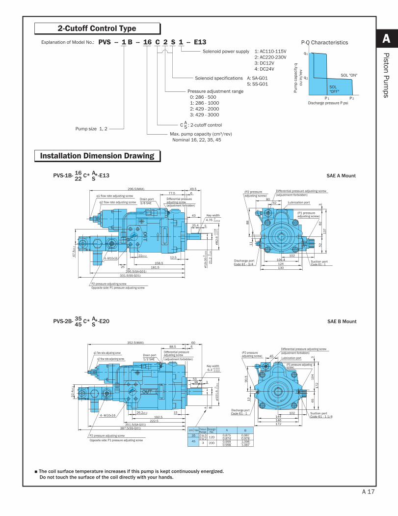
2-Cutoff Control Type
Installation Dimension Drawing
Explanation of Model No.: PVS -- 1 B -- 16 C 2 S 1 -- E13
PVS-1B- 16 AC* *-E1322 S
PVS-2B- 35 AC* *-E2045 S
■ The coil surface temperature increases if this pump is kept continuously energized. Do not touch the surface of the coil directly with your hands.
Discharge pressure P psi
Pum
p ca
paci
ty q
cu
in/r
ev
P-Q Characteristics
SOL"OFF"
SOL "ON"
P 1
q1
q2
P 2
Pressure adjustment range 0: 286 - 500 1: 286 - 1000 2: 429 - 2000 3: 429 - 3000
C : 2-cutoff controlAS
Max. pump capacity (cm³/rev) Nominal 16, 22, 35, 45
Pump size 1, 2
1: AC110-115V2: AC220-230V3: DC12V4: DC24V
Solenoid power supply
A: SA-G01S: SS-G01
Solenoid specifications
NACH
I
3/8 SAE
4–M10x16
525.4
12.5
158.5
22±0.247.5
±0.2
677.5
181.5
49.5
43
331.5(SS-G01)
25295.5(SA-G01)
296.5(MAX)
106.4
130
5211
124
8213
7342
88
80
102
4.76 0–0.012
21.2
19.0
50 –0
.25
0 –0.0
21φ
82.6
–0.0
36–0
.071
φ
24
Code 61 - 3/4 Suction port
q1 flow rate adjusting screw
q2 flow rate adjusting screwDrain port
Key width
Lubrication port
Differential pressure adjusting screw(adjustment forbidden)
(P2 pressure adjusting screw)
Discharge port
(P1 pressure adjusting screw)
Code 61 - 1
φ
Differential pressure adjusting screw (adjustment forbidden)
P2 pressure adjusting screwOpposite side: P1 pressure adjusting screw
NACH
I
1/2 SAE
4–M10x16
P2 pressure adjusting screwOpposite side: P1 pressure adjusting screw
144146172
65
45
1390
.5
102
104
317
2
53338
6
192.51526.2±0.2
52.4
±0.2
88.5
222.5
352.5(MAX) 60
351.5(SA-G01)387.5(SS-G01)
A B
Code 61 - 1 1/4Code 61 - 1
6.3+0.015–0.010
101.
6 –0.
051
0φ
28φ
q1 flow rate adjusting screwDrain port
q2 flow rate adjusting screw
Key width
Differential pressure adjusting screw (adjustment forbidden)(P2 pressure
adjusting screw) Lubrication port
(P1 pressure adjusting screw)
Discharge portSuction port
(adjustment forbidden)
Differential pressure adjusting screw
SAE A Mount
SAE B Mount
3
12D
20D
A Bcm3/rev
0.9870.978
35
45
PressureRange
DesignNo.
0 to 30 to 2
1.0961.087
0.8750.8740.9990.998
A 18
A
Piston Pumps
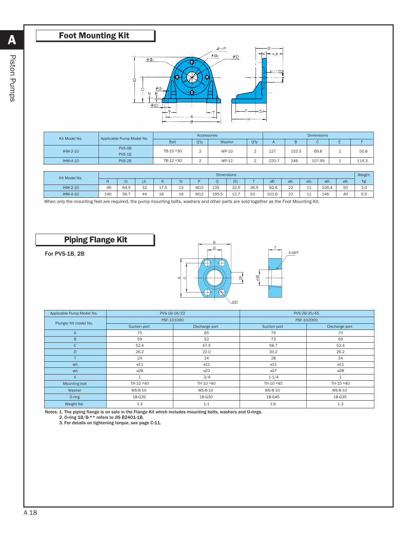
Foot Mounting Kit
Piping Flange Kit
Kit Model No. Applicable Pump Model No.Accessories Dimensions
Bolt Q'ty Washer Q'ty A B C E F
IHM-2-10PVS-0BPVS-1B
TB-10 ×30 2 WP-10 2 127.7 152.5 69.8 1 150.8
IHM-4-10 PVS-2B TB-12 ×30 2 WP-12 2 220.7 246.5 107.95 1 114.3
Kit Model No.Dimensions Weight
kgH (I) (J) K N P Q (S) T φD φd1 φd2 φd3 φd4
IHM-2-10 96 64.5 32 17.5 13 M10 135 32.5 36.5 82.6 22 11 106.4 50 2.0IHM-4-10 140 56.7 44 16 16 M12 195.5 12.7 53 101.6 22 11 146 40 5.5
When only the mounting feet are required, the pump mounting bolts, washers and other parts are sold together as the Foot Mounting Kit.
For PVS-1B, 2B
Notes: 1. The piping flange is on sale in the Flange Kit which includes mounting bolts, washers and O-rings. 2. O-ring 1B/B-** refers to JIS B2401-1B. 3. For details on tightening torque, see page C-11.
Applicable Pump Model No. PVS-1B-16/22 PVS-2B-35/45
Plunger Kit model No.PSF-101000 PSF-102000
Suction port Discharge port Suction port Discharge portA 70 65 79 70B 59 52 73 59C 52.4 47.5 58.7 52.4D 26.2 22.0 30.2 26.2T 24 24 28 24φd1 φ11 φ11 φ11 φ11φd2 φ28 φ22 φ37 φ28X 1 3/4 1-1/4 1
Mounting bolt TH-10 ×40 TH-10 ×40 TH-10 ×45 TH-10 ×40
Washer WS-B-10 WS-B-10 WS-B-10 WS-B-10
O-ring 1B-G35 1B-G30 1B-G45 1B-G35
Weight lbs 1.3 1.1 1.6 1.3
X-NPT