research on the volumetric efficiency of 2d piston pumps
TRANSCRIPT
energies
Article
Research on the Volumetric Efficiency of 2D PistonPumps with a Balanced Force
Yu Huang, Jian Ruan *, Yong Chen, Chuan Ding and Sheng Li
Key Laboratory of Special Purpose Equipment and Advanced Manufacturing Technology, Ministry of Education& Zhejiang Province, Zhejiang University of Technology, Hangzhou 310014, China;[email protected] (Y.H.); [email protected] (Y.C.); [email protected] (C.D.);[email protected] (S.L.)* Correspondence: [email protected]
Received: 15 July 2020; Accepted: 2 September 2020; Published: 14 September 2020�����������������
Abstract: Axial piston pumps with high rotational speeds are required in many fields to increase thepower-to-weight ratio. However, three main sliding friction pairs in the pump restrict the increase inrotational speed. To solve this problem, we propose a 2D piston pump with a balanced force thatcontains a sliding friction pair. Firstly, the mechanical structure and working principle of the pump aredescribed. Then, the pump volumetric efficiency is studied by mathematical modeling, and volumetriclosses containing backflow and leakage are analyzed and discussed from the perspectives of loadpressure and rotational speed. A test bench that verifies the mathematical model is built to measurethe volumetric efficiency of the tested pump. We have found that the increase in rotational speed canhelp to increase the pump volumetric efficiency, and the mathematical model is consistent with thetested data for 1000 rpm but demonstrates a remarkable difference from the tested data for 3000 rpm.Thus, the temperature field of the pump and the viscosity-temperature characteristics of the oil mustbe taken into account to increase volumetric efficiency further.
Keywords: 2D piston pump; backflow; leakage; volumetric losses
1. Introduction
Hydraulic systems are widely used in many fields because of their high power density,quick dynamic response, and strong load capacity [1–3]. In recent years, due to their highpower-to-weight ratio, electro-hydrostatic actuator (EHA)-installed axial piston pumps as the oilsource are used to replace the centrifugal hydraulic system, which uses centrifugal pumps as the oilsource in the aerospace industry [4].
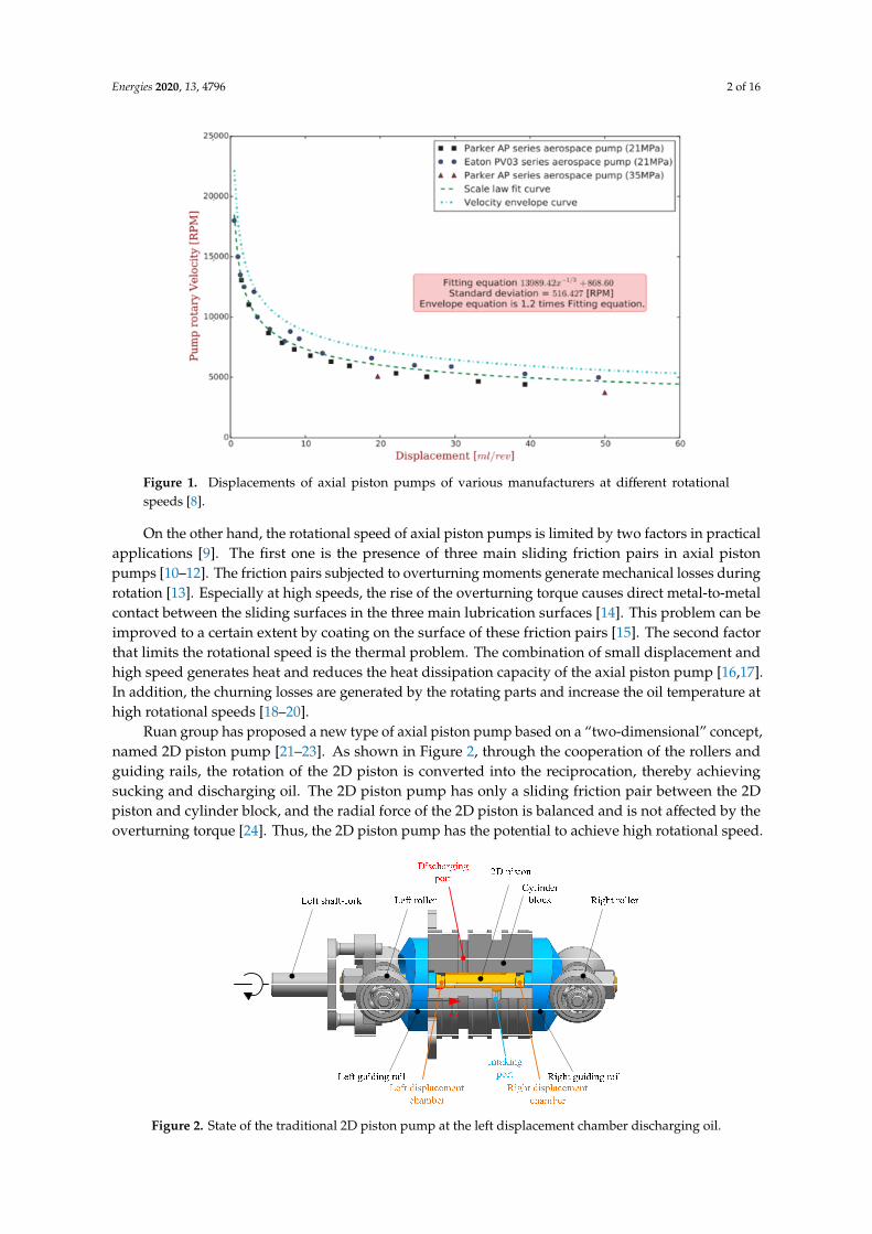
A high power density is the most important requirement for axial piston pumps used inthe aerospace industry, and the power-to-weight ratio of energy components needs to be furtherimproved [5]. This is often achieved by increasing rotational speed [6]. The displacements of axialpiston pumps of various manufacturers at various rotational speeds are shown in Figure 1. In aerospaceapplications, the rotational speed of the axial piston pump is required to be greater than 10,000 rpm [7].When the rotational speed exceeds 10,000 rpm, as shown in Figure 1, the pump displacement decreasesto less than 5 mL/r. Increasing the rotational speed and reducing the displacement of the pumpcan increase the power density, known as the “reduction effect”. This reduction effect is significantfor low rotational speed pumps, but it becomes less noticeable when the rotational speed exceeds10,000 rpm [6].
Energies 2020, 13, 4796; doi:10.3390/en13184796 www.mdpi.com/journal/energies
Energies 2020, 13, 4796 2 of 16Energies 2020, 13, x FOR PEER REVIEW 2 of 16
Figure 1. Displacements of axial piston pumps of various manufacturers at different rotational speeds [8].
On the other hand, the rotational speed of axial piston pumps is limited by two factors in practical applications [9]. The first one is the presence of three main sliding friction pairs in axial piston pumps [10–12]. The friction pairs subjected to overturning moments generate mechanical losses during rotation [13]. Especially at high speeds, the rise of the overturning torque causes direct metal-to-metal contact between the sliding surfaces in the three main lubrication surfaces [14]. This problem can be improved to a certain extent by coating on the surface of these friction pairs [15]. The second factor that limits the rotational speed is the thermal problem. The combination of small displacement and high speed generates heat and reduces the heat dissipation capacity of the axial piston pump [16,17]. In addition, the churning losses are generated by the rotating parts and increase the oil temperature at high rotational speeds [18–20].
Ruan group has proposed a new type of axial piston pump based on a “two-dimensional” concept, named 2D piston pump [21–23]. As shown in Figure 2, through the cooperation of the rollers and guiding rails, the rotation of the 2D piston is converted into the reciprocation, thereby achieving sucking and discharging oil. The 2D piston pump has only a sliding friction pair between the 2D piston and cylinder block, and the radial force of the 2D piston is balanced and is not affected by the overturning torque [24]. Thus, the 2D piston pump has the potential to achieve high rotational speed.
Figure 2. State of the traditional 2D piston pump at the left displacement chamber discharging oil.
Figure 1. Displacements of axial piston pumps of various manufacturers at different rotationalspeeds [8].
On the other hand, the rotational speed of axial piston pumps is limited by two factors in practicalapplications [9]. The first one is the presence of three main sliding friction pairs in axial pistonpumps [10–12]. The friction pairs subjected to overturning moments generate mechanical losses duringrotation [13]. Especially at high speeds, the rise of the overturning torque causes direct metal-to-metalcontact between the sliding surfaces in the three main lubrication surfaces [14]. This problem can beimproved to a certain extent by coating on the surface of these friction pairs [15]. The second factorthat limits the rotational speed is the thermal problem. The combination of small displacement andhigh speed generates heat and reduces the heat dissipation capacity of the axial piston pump [16,17].In addition, the churning losses are generated by the rotating parts and increase the oil temperature athigh rotational speeds [18–20].
Ruan group has proposed a new type of axial piston pump based on a “two-dimensional” concept,named 2D piston pump [21–23]. As shown in Figure 2, through the cooperation of the rollers andguiding rails, the rotation of the 2D piston is converted into the reciprocation, thereby achievingsucking and discharging oil. The 2D piston pump has only a sliding friction pair between the 2Dpiston and cylinder block, and the radial force of the 2D piston is balanced and is not affected by theoverturning torque [24]. Thus, the 2D piston pump has the potential to achieve high rotational speed.
Energies 2020, 13, x FOR PEER REVIEW 2 of 16
Figure 1. Displacements of axial piston pumps of various manufacturers at different rotational speeds [8].
On the other hand, the rotational speed of axial piston pumps is limited by two factors in practical applications [9]. The first one is the presence of three main sliding friction pairs in axial piston pumps [10–12]. The friction pairs subjected to overturning moments generate mechanical losses during rotation [13]. Especially at high speeds, the rise of the overturning torque causes direct metal-to-metal contact between the sliding surfaces in the three main lubrication surfaces [14]. This problem can be improved to a certain extent by coating on the surface of these friction pairs [15]. The second factor that limits the rotational speed is the thermal problem. The combination of small displacement and high speed generates heat and reduces the heat dissipation capacity of the axial piston pump [16,17]. In addition, the churning losses are generated by the rotating parts and increase the oil temperature at high rotational speeds [18–20].
Ruan group has proposed a new type of axial piston pump based on a “two-dimensional” concept, named 2D piston pump [21–23]. As shown in Figure 2, through the cooperation of the rollers and guiding rails, the rotation of the 2D piston is converted into the reciprocation, thereby achieving sucking and discharging oil. The 2D piston pump has only a sliding friction pair between the 2D piston and cylinder block, and the radial force of the 2D piston is balanced and is not affected by the overturning torque [24]. Thus, the 2D piston pump has the potential to achieve high rotational speed.
Figure 2. State of the traditional 2D piston pump at the left displacement chamber discharging oil.
However, vibration is generated by the pump at high rotational speeds. When the 2D piston rotates, the cylinder block is moved by a force F1, which is generated by the rollers. The force acts on the left side of the cylinder block at the left displacement chamber discharging oil, and the force acts on the right side of the cylinder block at the right displacement chamber discharging oil. Due to the
Figure 2. State of the traditional 2D piston pump at the left displacement chamber discharging oil.
Energies 2020, 13, 4796 3 of 16
However, vibration is generated by the pump at high rotational speeds. When the 2D pistonrotates, the cylinder block is moved by a force F1, which is generated by the rollers. The force acts onthe left side of the cylinder block at the left displacement chamber discharging oil, and the force actson the right side of the cylinder block at the right displacement chamber discharging oil. Due to thetraditional 2D pump designed to discharge oil alternately between the left and right displacementchambers, the cylinder block is moved by an alternate force and generates vibration [25].
To solve this problem, we propose a 2D piston pump with a balanced force using a well-balancedforce. By adding a balancing set, the cylinder block is subjected to a pair of balanced forces,thereby eliminating the vibration [26]. Firstly, the mechanical structure and working principle of theproposed piston pump are described in Section 2. Then, the volumetric efficiency of the pump isresearched through mathematical modeling in Section 3. The pump volumetric losses are analyzedand discussed from the perspectives of load pressure and rotational speed in Section 4. Finally, a testbench is built to measure the volumetric efficiency of the pump and verify the mathematical model.
2. Mechanical Structure and Working Principle of the 2D Piston Pump with a Balanced Force
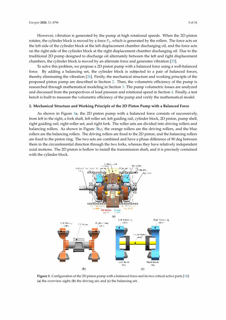
As shown in Figure 3a, the 2D piston pump with a balanced force consists of successively,from left to the right, a fork shaft, left roller set, left guiding rail, cylinder block, 2D piston, pump shell,right guiding rail, right roller set, and right fork. The roller sets are divided into driving rollers andbalancing rollers. As shown in Figure 3b,c, the orange rollers are the driving rollers, and the bluerollers are the balancing rollers. The driving rollers are fixed to the 2D piston, and the balancing rollersare fixed to the piston ring. The two sets are combined and have a phase difference of 90 deg betweenthem in the circumferential direction through the two forks, whereas they have relatively independentaxial motions. The 2D piston is hollow to install the transmission shaft, and it is precisely containedwith the cylinder block.
Energies 2020, 13, x FOR PEER REVIEW 3 of 16
traditional 2D pump designed to discharge oil alternately between the left and right displacement chambers, the cylinder block is moved by an alternate force and generates vibration [25].
To solve this problem, we propose a 2D piston pump with a balanced force using a well-balanced force. By adding a balancing set, the cylinder block is subjected to a pair of balanced forces, thereby eliminating the vibration [26]. Firstly, the mechanical structure and working principle of the proposed piston pump are described in Section 2. Then, the volumetric efficiency of the pump is researched through mathematical modeling in Section 3. The pump volumetric losses are analyzed and discussed from the perspectives of load pressure and rotational speed in Section 4. Finally, a test bench is built to measure the volumetric efficiency of the pump and verify the mathematical model.
2. Mechanical Structure and Working Principle of the 2D Piston Pump with a Balanced Force
As shown in Figure 3a, the 2D piston pump with a balanced force consists of successively, from left to the right, a fork shaft, left roller set, left guiding rail, cylinder block, 2D piston, pump shell, right guiding rail, right roller set, and right fork. The roller sets are divided into driving rollers and balancing rollers. As shown in Figure 3b,c, the orange rollers are the driving rollers, and the blue rollers are the balancing rollers. The driving rollers are fixed to the 2D piston, and the balancing rollers are fixed to the piston ring. The two sets are combined and have a phase difference of 90 deg between them in the circumferential direction through the two forks, whereas they have relatively independent axial motions. The 2D piston is hollow to install the transmission shaft, and it is precisely contained with the cylinder block.
(a)
(b) (c)
Figure 3. Configuration of the 2D piston pump with a balanced force and its two critical active parts [18]: (a) the overview sight; (b) the driving set; and (c) the balancing set.
The left and right displacement chambers, both having the same working principle, are composed of the 2D piston, piston rings, and cylinder block, but have a phase difference of 90 deg.
Figure 3. Configuration of the 2D piston pump with a balanced force and its two critical active parts [18]:(a) the overview sight; (b) the driving set; and (c) the balancing set.

Energies 2020, 13, 4796 4 of 16
The left and right displacement chambers, both having the same working principle, are composedof the 2D piston, piston rings, and cylinder block, but have a phase difference of 90 deg. Taking the leftdisplacement chamber as an example, the working principle of oil suction and discharge is introduced.
The pump’s state described in Figure 4a is assumed to be zero at the initial state, where the leftdisplacement chamber is at the maximum volume and prepares to discharge oil. From Figure 4a–c,the 2D piston rotates from 0 deg to 90 deg. The left displacement chamber is compressed from themaximum, causing the oil to be discharged into the discharging port out of the left displacementchamber. From Figure 4a–c, the 2D piston rotates from 90 deg to 180 deg. The left displacementchamber expands from the minimum, causing the oil to be sucked from the intaking port into the leftdisplacement chamber.
Energies 2020, 13, x FOR PEER REVIEW 4 of 16
Taking the left displacement chamber as an example, the working principle of oil suction and discharge is introduced.
The pump’s state described in Figure 4a is assumed to be zero at the initial state, where the left displacement chamber is at the maximum volume and prepares to discharge oil. From Figure 4a–c, the 2D piston rotates from 0 deg to 90 deg. The left displacement chamber is compressed from the maximum, causing the oil to be discharged into the discharging port out of the left displacement chamber. From Figure 4a–c, the 2D piston rotates from 90 deg to 180 deg. The left displacement chamber expands from the minimum, causing the oil to be sucked from the intaking port into the left displacement chamber.
(a) (b)
(c) (d)
Figure 4. A working period of the 2D piston pump with a balanced force [18]: (a) at the initial point of rotation, (b) at a rotational angle of 45 deg, (c) at a rotational angle of 90 deg, (d) at a rotational angle of 135 deg.
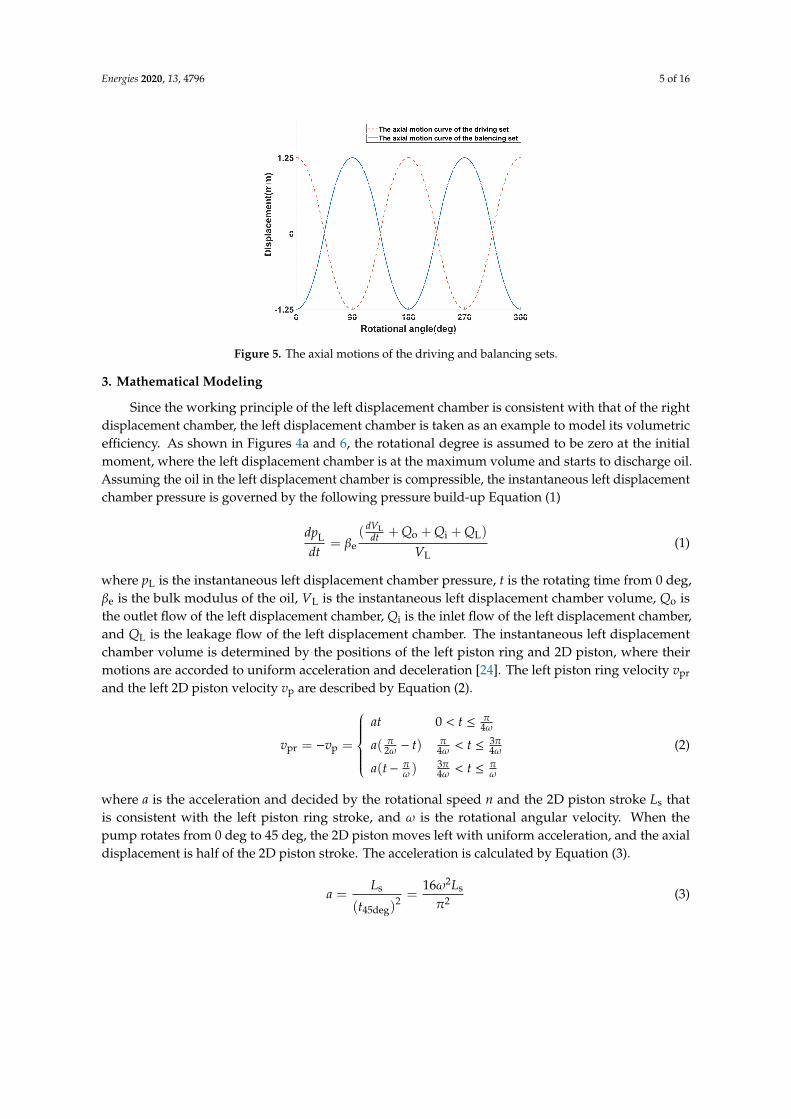
As soon as the left shaft-fork is rotated by a motor, both the driving and balancing sets are rotated at the same pace. When the rollers rotate under the constraint of the guiding rails, the rotation of the sets is transformed into the relative reciprocating motion. As shown in Figure 5, when the rollers rotate from 0 deg to 45 deg, the driving set moves left with uniform acceleration, and the balancing set moves right with a uniform acceleration, decreasing the volume of the left displacement chamber and increasing that of the right displacement chamber. Therefore, the force acting on the cylinder block by the driving set can be balanced by force from the balancing set.
Figure 4. A working period of the 2D piston pump with a balanced force [18]: (a) at the initial point ofrotation, (b) at a rotational angle of 45 deg, (c) at a rotational angle of 90 deg, (d) at a rotational angle of135 deg.
As soon as the left shaft-fork is rotated by a motor, both the driving and balancing sets are rotatedat the same pace. When the rollers rotate under the constraint of the guiding rails, the rotation of thesets is transformed into the relative reciprocating motion. As shown in Figure 5, when the rollersrotate from 0 deg to 45 deg, the driving set moves left with uniform acceleration, and the balancing setmoves right with a uniform acceleration, decreasing the volume of the left displacement chamber andincreasing that of the right displacement chamber. Therefore, the force acting on the cylinder block bythe driving set can be balanced by force from the balancing set.
Energies 2020, 13, 4796 5 of 16
Energies 2020, 13, x FOR PEER REVIEW 5 of 16
Figure 5. The axial motions of the driving and balancing sets.
3. Mathematical Modeling
Since the working principle of the left displacement chamber is consistent with that of the right displacement chamber, the left displacement chamber is taken as an example to model its volumetric efficiency. As shown in Figures 4a and 6, the rotational degree is assumed to be zero at the initial moment, where the left displacement chamber is at the maximum volume and starts to discharge oil. Assuming the oil in the left displacement chamber is compressible, the instantaneous left displacement chamber pressure is governed by the following pressure build-up Equation (1)
Lo i L
Le
L
( )=
dV Q Q Qdp dtdt V
β+ + +
(1)
where pL is the instantaneous left displacement chamber pressure, t is the rotating time from 0 deg, βe is the bulk modulus of the oil, VL is the instantaneous left displacement chamber volume, Qo is the outlet flow of the left displacement chamber, Qi is the inlet flow of the left displacement chamber, and QL is the leakage flow of the left displacement chamber. The instantaneous left displacement chamber volume is determined by the positions of the left piston ring and 2D piston, where their motions are accorded to uniform acceleration and deceleration [24]. The left piston ring velocity vpr
and the left 2D piston velocity vp are described by Equation (2).
pr p
04
3( )2 4 4
3( )4
at t
v v a t t
a t t
πω
π π πω ω ω
π π πω ω ω
< ≤= − = − < ≤ − < ≤
(2)
where a is the acceleration and decided by the rotational speed n and the 2D piston stroke Ls that is consistent with the left piston ring stroke, and ω is the rotational angular velocity. When the pump rotates from 0 deg to 45 deg, the 2D piston moves left with uniform acceleration, and the axial displacement is half of the 2D piston stroke. The acceleration is calculated by Equation (3).
2s s
2 245deg
16( )
L Lat
ωπ
= =
(3)
where t45deg is the rotating time from 0 deg to 45 deg. Integrating the left piston ring velocity and 2D piston velocity, the instantaneous left displacement chamber volume is calculated by Equation (4).
Figure 5. The axial motions of the driving and balancing sets.
3. Mathematical Modeling
Since the working principle of the left displacement chamber is consistent with that of the rightdisplacement chamber, the left displacement chamber is taken as an example to model its volumetricefficiency. As shown in Figures 4a and 6, the rotational degree is assumed to be zero at the initialmoment, where the left displacement chamber is at the maximum volume and starts to discharge oil.Assuming the oil in the left displacement chamber is compressible, the instantaneous left displacementchamber pressure is governed by the following pressure build-up Equation (1)
dpL
dt= βe
( dVLdt + Qo + Qi + QL)
VL(1)
where pL is the instantaneous left displacement chamber pressure, t is the rotating time from 0 deg,βe is the bulk modulus of the oil, VL is the instantaneous left displacement chamber volume, Qo isthe outlet flow of the left displacement chamber, Qi is the inlet flow of the left displacement chamber,and QL is the leakage flow of the left displacement chamber. The instantaneous left displacementchamber volume is determined by the positions of the left piston ring and 2D piston, where theirmotions are accorded to uniform acceleration and deceleration [24]. The left piston ring velocity vpr
and the left 2D piston velocity vp are described by Equation (2).
vpr = −vp =
at 0 < t ≤ π
4ω
a( π2ω − t) π4ω < t ≤ 3π
4ω
a(t− πω )
3π4ω < t ≤ π
ω
(2)
where a is the acceleration and decided by the rotational speed n and the 2D piston stroke Ls thatis consistent with the left piston ring stroke, and ω is the rotational angular velocity. When thepump rotates from 0 deg to 45 deg, the 2D piston moves left with uniform acceleration, and the axialdisplacement is half of the 2D piston stroke. The acceleration is calculated by Equation (3).
a =Ls
(t45deg)2 =
16ω2Ls
π2 (3)

Energies 2020, 13, 4796 6 of 16
where t45deg is the rotating time from 0 deg to 45 deg. Integrating the left piston ring velocity and 2Dpiston velocity, the instantaneous left displacement chamber volume is calculated by Equation (4).
VL =
VM − 2A· 12 at2 0 < t ≤ π4ω
VM −Aa π2
8ω2 + 2A· 12 a( π2ω − t)2 π4ω < t ≤ π
2ω
VM −Aa π2
8ω2 + 2A· 12 a(t− π2ω )
2 π2ω < t ≤ 3π
4ω
VM − 2A· 12 a(t− πω )
2 3π4ω < t ≤ π
ω
(4)
where VM is the maximum volume of the left displacement chamber. Equation (5) is obtained bydifferentiating Equation (4).
dVL
dt=
−2Aat 0 < t ≤ π
4ω
−2Aa( π2ω − t) π4ω < t ≤ 3π
4ω
−2Aa(t− πω )
3π4ω < t ≤ π
ω
(5)
The outlet flow and the inlet flow can be calculated by using the standard orifice Equations (6) and (7).
Qo = CdAout
√2∣∣∣pL − pLoad
∣∣∣ρ
sign(pL − pLoad) (6)
Qi = CdAin
√2∣∣∣pT − pL
∣∣∣ρ
sign(pL − pT) (7)
where Cd is the orifice coefficient, Aout and Ain are the open areas of the discharging ports andintaking ports, respectively, pLoad and pT are the pressures of the load and tank, respectively, and ρ isthe oil density.
Energies 2020, 13, x FOR PEER REVIEW 6 of 16
2M
22
M 2
L 22
M 2
2M
12 02 4
12 ( )8 2 2 4 2
1 32 ( )8 2 2 2 41 32 ( )2 4
V A at t
V Aa A a t tV
V Aa A a t t
V A a t t
πω
π π π πω ω ω ωπ π π πω ω ω ω
π π πω ω ω
− ⋅ < ≤ − + ⋅ − < ≤= − + ⋅ − < ≤ − ⋅ − < ≤
(4)
where VM is the maximum volume of the left displacement chamber. Equation (5) is obtained by differentiating Equation (4).
L
2 04
32 ( )2 4 4
32 ( )4
Aat t
dV Aa t tdt
Aa t t
πω
π π πω ω ω
π π πω ω ω
− < ≤= − − < ≤− − < ≤
(5)
The outlet flow and the inlet flow can be calculated by using the standard orifice Equations (6) and (7).
L Loado d out L Load
2sign( )
p pQ C A p p
ρ−
= −
(6)
T Li d in L T
2sign( )
p pQ C A p p
ρ−
= −
(7)
where Cd is the orifice coefficient, Aout and Ain are the open areas of the discharging ports and intaking ports, respectively, pLoad and pT are the pressures of the load and tank, respectively, and ρ is the oil density.
Figure 6. The maximum volume of the left displacement chamber.
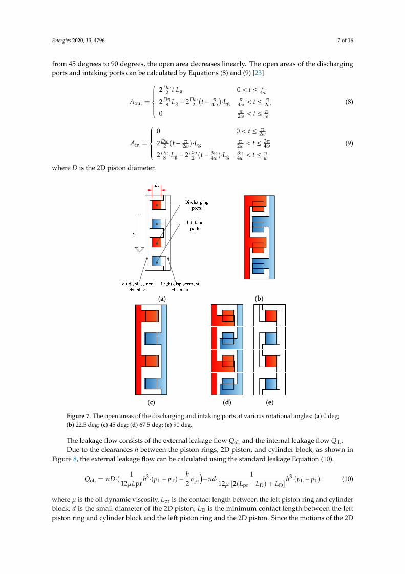
By expanding the outer circle of the 2D piston into a plane, as shown in Figure 7, when the pump rotates from 0 deg to 90 deg, the state that the left displacement chamber connects with the discharging ports can be described in detail. Because the rotational speed and port length Lg are constant, when the rotational angle is from 0 deg to 45 deg, the open area increases linearly; when the rotational angle is from 45 degrees to 90 degrees, the open area decreases linearly. The open areas of the discharging ports and intaking ports can be calculated by Equations (8) and (9) [23]
Figure 6. The maximum volume of the left displacement chamber.
By expanding the outer circle of the 2D piston into a plane, as shown in Figure 7, when the pumprotates from 0 deg to 90 deg, the state that the left displacement chamber connects with the dischargingports can be described in detail. Because the rotational speed and port length Lg are constant, when therotational angle is from 0 deg to 45 deg, the open area increases linearly; when the rotational angle is
Energies 2020, 13, 4796 7 of 16
from 45 degrees to 90 degrees, the open area decreases linearly. The open areas of the dischargingports and intaking ports can be calculated by Equations (8) and (9) [23]
Aout =
2 Dω
2 t·Lg 0 < t ≤ π4ω
2 Dπ8 Lg − 2 Dω
2 (t− π4ω )·Lg
π4ω < t ≤ π
2ω
0 π2ω < t ≤ π
ω
(8)
Ain =
0 0 < t ≤ π
2ω
2 Dω2 (t− π
2ω )·Lgπ
2ω < t ≤ 3π4ω
2 Dπ8 ·Lg − 2 Dω
2 (t− 3π4ω )·Lg
3π4ω < t ≤ π
ω
(9)
where D is the 2D piston diameter.
Energies 2020, 13, x FOR PEER REVIEW 7 of 16
g
out g g
2 02 4
2 2 ( )8 2 4 4 2
02
D t L t
D DA L t L t
t
ω πω
π ω π π πω ω ω
π πω ω
⋅ < ≤= − − ⋅ < ≤ < ≤
(8)
in g
g g
0 02
32 ( )2 2 2 4
3 32 2 ( )8 2 4 4
t
DA t L t
D DL t L t
πω
ω π π πω ω ω
π ω π π πω ω ω
< ≤= − ⋅ < ≤ ⋅ − − ⋅ < ≤
(9)
where D is the 2D piston diameter.
(a) (b)
(c) (d) (e)
Figure 7. The open areas of the discharging and intaking ports at various rotational angles: (a) 0 deg; (b) 22.5 deg; (c) 45 deg; (d) 67.5 deg; (e) 90 deg.
The leakage flow consists of the external leakage flow QoL and the internal leakage flow QiL. Due to the clearances h between the piston rings, 2D piston, and cylinder block, as shown in
Figure 8, the external leakage flow can be calculated using the standard leakage Equation (10).
3 3proL L T L T
pr pr D D
1 1= ( ( ) )+ ( )12 2 12 [2( ) ]
hQ D h p p v d h p pL L L L
π πμ μ
⋅ ⋅ − − ⋅ ⋅ −⋅ − +
(10)
where μ is the oil dynamic viscosity, Lpr is the contact length between the left piston ring and cylinder block, d is the small diameter of the 2D piston, LD is the minimum contact length between the left piston ring and cylinder block and the left piston ring and the 2D piston. Since the motions of the 2D
Figure 7. The open areas of the discharging and intaking ports at various rotational angles: (a) 0 deg;(b) 22.5 deg; (c) 45 deg; (d) 67.5 deg; (e) 90 deg.
The leakage flow consists of the external leakage flow QoL and the internal leakage flow QiL.Due to the clearances h between the piston rings, 2D piston, and cylinder block, as shown in
Figure 8, the external leakage flow can be calculated using the standard leakage Equation (10).
QoL = πD·(1
12µLprh3·(pL − pT) −
h2
vpr)+πd·
112µ·[2(Lpr − LD) + LD]
h3·(pL − pT) (10)
where µ is the oil dynamic viscosity, Lpr is the contact length between the left piston ring and cylinderblock, d is the small diameter of the 2D piston, LD is the minimum contact length between the leftpiston ring and cylinder block and the left piston ring and the 2D piston. Since the motions of the 2D
Energies 2020, 13, 4796 8 of 16
piston and left piston ring are relative, the external leakage between the left piston ring and 2D pistongenerated by the velocity is not considered. The length between the left piston ring and the cylinderblock is calculated by integrating Equation (2) [22].
Lpr =
LD + 12 at2 0 < t ≤ π
4ω
LD + a π2
16ω2 −12 a( π2ω − t)2 π
4ω < t ≤ π2ω
LD + a π2
16ω2 −12 a(t− π
2ω )2 π
2ω < t ≤ 3π4ω
LD + 12 a( πω − t)2 3π
4ω < t ≤ πω
(11)
Energies 2020, 13, x FOR PEER REVIEW 8 of 16
piston and left piston ring are relative, the external leakage between the left piston ring and 2D piston generated by the velocity is not considered. The length between the left piston ring and the cylinder block is calculated by integrating Equation (2) [22].
2D
22
D 2pr
22
D 2
2D
1 02 4
1 ( )16 2 2 4 2
1 3( )16 2 2 2 4
1 3( )2 4
L at t
L a a t tL
L a a t t
L a t t
πω
π π π πω ω ω ω
π π π πω ω ω ωπ π πω ω ω
+ < ≤ + − − < ≤= + − − < ≤ + − < ≤
(11)
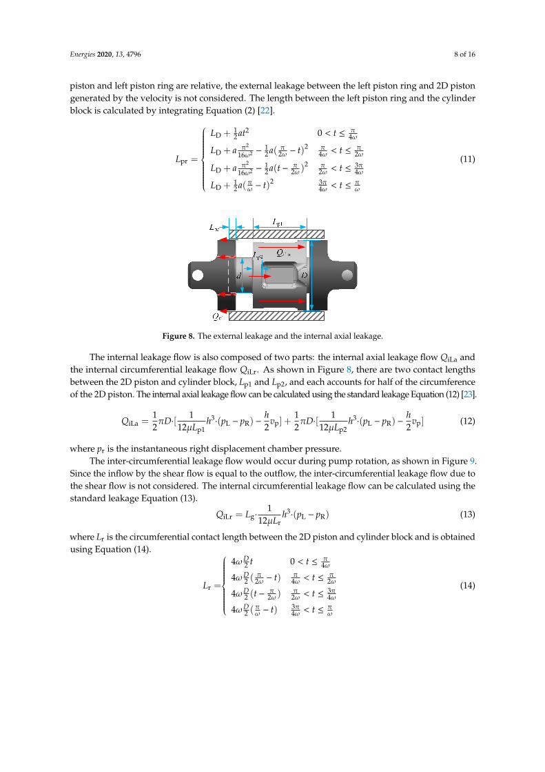
Figure 8. The external leakage and the internal axial leakage.
The internal leakage flow is also composed of two parts: the internal axial leakage flow QiLa and the internal circumferential leakage flow QiLr. As shown in Figure 8, there are two contact lengths between the 2D piston and cylinder block, Lp1 and Lp2, and each accounts for half of the circumference of the 2D piston. The internal axial leakage flow can be calculated using the standard leakage Equation (12) [23].
3 3iLa L R p L R p
p1 p2
1 1 1 1= [ ]+ [ ]2 12 2 2 12 2
h hQ D h p p v D h p p vL L
π πμ μ
⋅ ⋅ − − ⋅ ⋅ − −( ) ( )
(12)
where pr is the instantaneous right displacement chamber pressure. The inter-circumferential leakage flow would occur during pump rotation, as shown in Figure
9. Since the inflow by the shear flow is equal to the outflow, the inter-circumferential leakage flow due to the shear flow is not considered. The internal circumferential leakage flow can be calculated using the standard leakage Equation (13).
3giLr L R
r
1=12
Q L h p pLμ
⋅ ⋅ −( )
(13)
where Lr is the circumferential contact length between the 2D piston and cylinder block and is obtained using Equation (14).
(14) r
4 02 4
4 ( )2 2 4 2=
34 ( )2 2 2 4
34 ( )2 4
D t t
D t tL
D t t
D t t
πωω
π π πωω ω ω
π π πωω ω ω
π π πωω ω ω
< ≤ − < ≤ − < ≤ − < ≤
Figure 8. The external leakage and the internal axial leakage.
The internal leakage flow is also composed of two parts: the internal axial leakage flow QiLa andthe internal circumferential leakage flow QiLr. As shown in Figure 8, there are two contact lengthsbetween the 2D piston and cylinder block, Lp1 and Lp2, and each accounts for half of the circumferenceof the 2D piston. The internal axial leakage flow can be calculated using the standard leakage Equation (12) [23].
QiLa =12πD·[
112µLp1
h3·(pL − pR) −
h2
vp] +12πD·[
112µLp2
h3·(pL − pR) −
h2
vp] (12)
where pr is the instantaneous right displacement chamber pressure.The inter-circumferential leakage flow would occur during pump rotation, as shown in Figure 9.
Since the inflow by the shear flow is equal to the outflow, the inter-circumferential leakage flow due tothe shear flow is not considered. The internal circumferential leakage flow can be calculated using thestandard leakage Equation (13).
QiLr = Lg·1
12µLrh3·(pL − pR) (13)
where Lr is the circumferential contact length between the 2D piston and cylinder block and is obtainedusing Equation (14).
Lr =
4ωD2 t 0 < t ≤ π
4ω
4ωD2 (
π2ω − t) π
4ω < t ≤ π2ω
4ωD2 (t−
π2ω )
π2ω < t ≤ 3π
4ω
4ωD2 (
πω − t) 3π
4ω < t ≤ πω
(14)
Energies 2020, 13, 4796 9 of 16Energies 2020, 13, x FOR PEER REVIEW 9 of 16
(a) (b) (c)
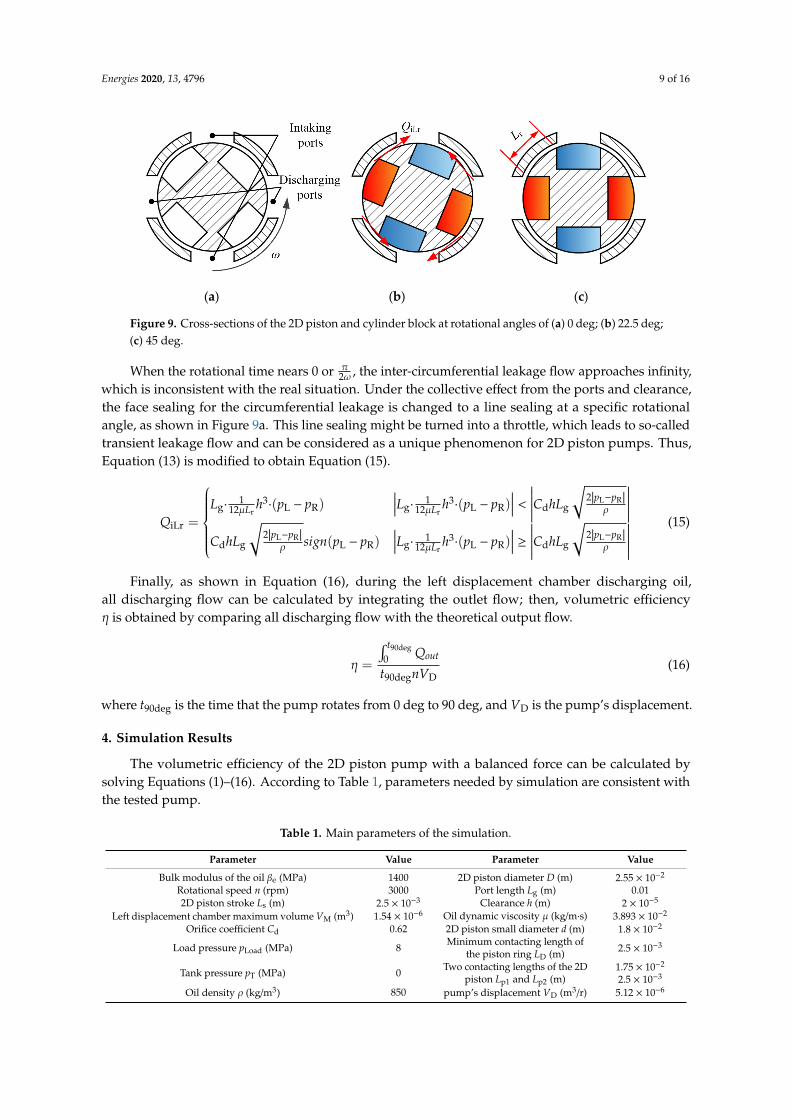
Figure 9. Cross-sections of the 2D piston and cylinder block at rotational angles of (a) 0 deg; (b) 22.5 deg; (c) 45 deg.
When the rotational time nears 0 or , the inter-circumferential leakage flow approaches infinity, which is inconsistent with the real situation. Under the collective effect from the ports and clearance, the face sealing for the circumferential leakage is changed to a line sealing at a specific rotational angle, as shown in Figure 9a. This line sealing might be turned into a throttle, which leads to so-called transient leakage flow and can be considered as a unique phenomenon for 2D piston pumps. Thus, Equation (13) is modified to obtain Equation (15).
L R3 3g g gL R L R d
r r
iLr
L R L R3g g gd L R L R d
r
21 112 12
2 21( )12
p pL h p p L h p p C hL
L LQ
p p p pC hL sign p p L h p p C hL
L
μ μ ρ
ρ μ ρ
− ⋅ ⋅ − ⋅ ⋅ − <= − −
− ⋅ ⋅ − ≥
( ) ( )
( )
(15)
Finally, as shown in Equation (16), during the left displacement chamber discharging oil, all discharging flow can be calculated by integrating the outlet flow; then, volumetric efficiency η is obtained by comparing all discharging flow with the theoretical output flow.
90deg
0
90deg D=
t
outQ
t nVη
(16)
where t90deg is the time that the pump rotates from 0 deg to 90 deg, and VD is the pump’s displacement.
4. Simulation Results
The volumetric efficiency of the 2D piston pump with a balanced force can be calculated by solving Equations (1)–(16). According to Table 1, parameters needed by simulation are consistent with the tested pump.
Table 1. Main parameters of the simulation.
Parameter Value Parameter Value Bulk modulus of the oil βe (MPa) 1400 2D piston diameter D (m) 2.55 × 10⁻²
Rotational speed n (rpm) 3000 Port length Lg (m) 0.01 2D piston stroke Ls (m) 2.5 × 10⁻³ Clearance h (m) 2 × 10⁻⁵
Left displacement chamber maximum volume VM
(m3) 1.54 × 10⁻⁶ Oil dynamic viscosity μ (kg/m·s) 3.893 × 10⁻²
Orifice coefficient Cd 0.62 2D piston small diameter d (m) 1.8 × 10⁻²
Load pressure pLoad (MPa) 8 Minimum contacting length of the
piston ring LD (m) 2.5 × 10⁻³
Tank pressure pT (MPa) 0 Two contacting lengths of the 2D
piston Lp1 and Lp2 (m) 1.75 × 10⁻² 2.5 × 10⁻³
Oil density ρ (kg/m3) 850 pump’s displacement VD (m3/r) 5.12 × 10⁻⁶
Figure 9. Cross-sections of the 2D piston and cylinder block at rotational angles of (a) 0 deg; (b) 22.5 deg;(c) 45 deg.
When the rotational time nears 0 or π2ω , the inter-circumferential leakage flow approaches infinity,
which is inconsistent with the real situation. Under the collective effect from the ports and clearance,the face sealing for the circumferential leakage is changed to a line sealing at a specific rotationalangle, as shown in Figure 9a. This line sealing might be turned into a throttle, which leads to so-calledtransient leakage flow and can be considered as a unique phenomenon for 2D piston pumps. Thus,Equation (13) is modified to obtain Equation (15).
QiLr =
Lg·
112µLr
h3·(pL − pR)
∣∣∣∣Lg·1
12µLrh3·(pL − pR)
∣∣∣∣ < ∣∣∣∣∣∣CdhLg
√2|pL−pR|
ρ
∣∣∣∣∣∣CdhLg
√2|pL−pR|
ρ sign(pL − pR)∣∣∣∣Lg·
112µLr
h3·(pL − pR)
∣∣∣∣ ≥ ∣∣∣∣∣∣CdhLg
√2|pL−pR|
ρ
∣∣∣∣∣∣(15)
Finally, as shown in Equation (16), during the left displacement chamber discharging oil,all discharging flow can be calculated by integrating the outlet flow; then, volumetric efficiencyη is obtained by comparing all discharging flow with the theoretical output flow.
η =
∫ t90deg
0 Qout
t90degnVD(16)
where t90deg is the time that the pump rotates from 0 deg to 90 deg, and VD is the pump’s displacement.
4. Simulation Results
The volumetric efficiency of the 2D piston pump with a balanced force can be calculated bysolving Equations (1)–(16). According to Table 1, parameters needed by simulation are consistent withthe tested pump.
Table 1. Main parameters of the simulation.
Parameter Value Parameter Value
Bulk modulus of the oil βe (MPa) 1400 2D piston diameter D (m) 2.55 × 10⁻²
Rotational speed n (rpm) 3000 Port length Lg (m) 0.012D piston stroke Ls (m) 2.5 × 10⁻³ Clearance h (m) 2 × 10⁻⁵
Left displacement chamber maximum volume VM (m3) 1.54 × 10⁻⁶ Oil dynamic viscosity µ (kg/m·s) 3.893 × 10⁻²
Orifice coefficient Cd 0.62 2D piston small diameter d (m) 1.8 × 10⁻²
Load pressure pLoad (MPa) 8 Minimum contacting length ofthe piston ring LD (m) 2.5 × 10⁻³
Tank pressure pT (MPa) 0 Two contacting lengths of the 2Dpiston Lp1 and Lp2 (m)
1.75 × 10⁻²
2.5 × 10⁻³
Oil density ρ (kg/m3) 850 pump’s displacement VD (m3/r) 5.12 × 10⁻⁶

Energies 2020, 13, 4796 10 of 16
The volumetric efficiency is affected by backflow and leakage. This paper describes their effectson volumetric efficiency in detail from the perspectives of load pressure and rotational speed.
The positive flow rate is assumed as the outflow from the left displacement chamber.
4.1. Backflow
When the left displacement chamber is connected to the discharging ports, backflow is generateddue to the instantaneous left displacement chamber pressure, which is lower than the load pressure.
As shown in Figure 10, the flow peak and the duration of the backflow increase with the increasein load pressure. As the load pressure increases, the pressure difference between the instantaneousleft displacement chamber pressure and load pressure increases at a rotational angle of 0 deg; thus,more flow is needed to help the left displacement chamber establish the pressure to discharge oil.
Energies 2020, 13, x FOR PEER REVIEW 10 of 16
The volumetric efficiency is affected by backflow and leakage. This paper describes their effects on volumetric efficiency in detail from the perspectives of load pressure and rotational speed.
The positive flow rate is assumed as the outflow from the left displacement chamber.
4.1. Backflow
When the left displacement chamber is connected to the discharging ports, backflow is generated due to the instantaneous left displacement chamber pressure, which is lower than the load pressure.
As shown in Figure 10, the flow peak and the duration of the backflow increase with the increase in load pressure. As the load pressure increases, the pressure difference between the instantaneous left displacement chamber pressure and load pressure increases at a rotational angle of 0 deg; thus, more flow is needed to help the left displacement chamber establish the pressure to discharge oil.
(a) (b)
Figure 10. The outflow at load pressures 1 MPa, 3 MPa, 5 MPa, and 8 MPa for rotational angle ranges (a) 0–90 deg and (b) 0–4.5 deg.
As shown in Figure 11, the flow peak of the backflow increases with the rise in rotational speed. Due to the different rotational speeds, although the angle range of the backflow increases as the rotational speed increases, the duration of the backflow decreases. Since the load pressure is constant, the total amount of demanded backflow remains constant, and the flow peak of the backflow increases due to the decrease in the duration of the backflow.
(a) (b)
Figure 11. The outflow at rotational speeds of 1000 rpm, 2000 rpm, and 3000 rpm at angle ranges of (a) 0–90 deg and (b) 0–4.5 deg.
Figure 10. The outflow at load pressures 1 MPa, 3 MPa, 5 MPa, and 8 MPa for rotational angle ranges(a) 0–90 deg and (b) 0–4.5 deg.
As shown in Figure 11, the flow peak of the backflow increases with the rise in rotational speed.Due to the different rotational speeds, although the angle range of the backflow increases as therotational speed increases, the duration of the backflow decreases. Since the load pressure is constant,the total amount of demanded backflow remains constant, and the flow peak of the backflow increasesdue to the decrease in the duration of the backflow.
Energies 2020, 13, x FOR PEER REVIEW 10 of 16
The volumetric efficiency is affected by backflow and leakage. This paper describes their effects on volumetric efficiency in detail from the perspectives of load pressure and rotational speed.
The positive flow rate is assumed as the outflow from the left displacement chamber.
4.1. Backflow
When the left displacement chamber is connected to the discharging ports, backflow is generated due to the instantaneous left displacement chamber pressure, which is lower than the load pressure.
As shown in Figure 10, the flow peak and the duration of the backflow increase with the increase in load pressure. As the load pressure increases, the pressure difference between the instantaneous left displacement chamber pressure and load pressure increases at a rotational angle of 0 deg; thus, more flow is needed to help the left displacement chamber establish the pressure to discharge oil.
(a) (b)
Figure 10. The outflow at load pressures 1 MPa, 3 MPa, 5 MPa, and 8 MPa for rotational angle ranges (a) 0–90 deg and (b) 0–4.5 deg.
As shown in Figure 11, the flow peak of the backflow increases with the rise in rotational speed. Due to the different rotational speeds, although the angle range of the backflow increases as the rotational speed increases, the duration of the backflow decreases. Since the load pressure is constant, the total amount of demanded backflow remains constant, and the flow peak of the backflow increases due to the decrease in the duration of the backflow.
(a) (b)
Figure 11. The outflow at rotational speeds of 1000 rpm, 2000 rpm, and 3000 rpm at angle ranges of (a) 0–90 deg and (b) 0–4.5 deg.
Figure 11. The outflow at rotational speeds of 1000 rpm, 2000 rpm, and 3000 rpm at angle ranges of(a) 0–90 deg and (b) 0–4.5 deg.
Energies 2020, 13, 4796 11 of 16
4.2. Leakage
The leakage of the 2D piston pump with a balanced force is composed of external leakage,internal axial leakage, and internal circumferential leakage.
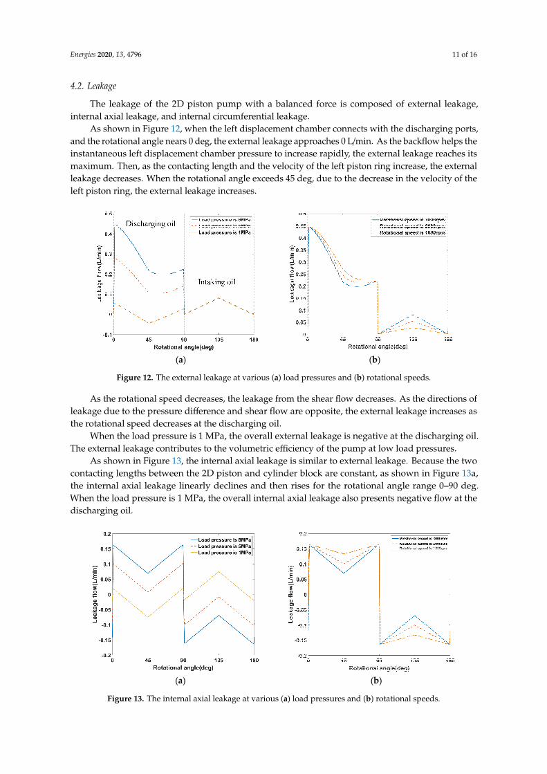
As shown in Figure 12, when the left displacement chamber connects with the discharging ports,and the rotational angle nears 0 deg, the external leakage approaches 0 L/min. As the backflow helps theinstantaneous left displacement chamber pressure to increase rapidly, the external leakage reaches itsmaximum. Then, as the contacting length and the velocity of the left piston ring increase, the externalleakage decreases. When the rotational angle exceeds 45 deg, due to the decrease in the velocity of theleft piston ring, the external leakage increases.
Energies 2020, 13, x FOR PEER REVIEW 11 of 16
4.2. Leakage
The leakage of the 2D piston pump with a balanced force is composed of external leakage, internal axial leakage, and internal circumferential leakage.
As shown in Figure 12, when the left displacement chamber connects with the discharging ports, and the rotational angle nears 0 deg, the external leakage approaches 0 L/min. As the backflow helps the instantaneous left displacement chamber pressure to increase rapidly, the external leakage reaches its maximum. Then, as the contacting length and the velocity of the left piston ring increase, the external leakage decreases. When the rotational angle exceeds 45 deg, due to the decrease in the velocity of the left piston ring, the external leakage increases.
(a) (b)
Figure 12. The external leakage at various (a) load pressures and (b) rotational speeds.
As the rotational speed decreases, the leakage from the shear flow decreases. As the directions of leakage due to the pressure difference and shear flow are opposite, the external leakage increases as the rotational speed decreases at the discharging oil.
When the load pressure is 1 MPa, the overall external leakage is negative at the discharging oil. The external leakage contributes to the volumetric efficiency of the pump at low load pressures.
As shown in Figure 13, the internal axial leakage is similar to external leakage. Because the two contacting lengths between the 2D piston and cylinder block are constant, as shown in Figure 13a, the internal axial leakage linearly declines and then rises for the rotational angle range 0–90 deg. When the load pressure is 1 MPa, the overall internal axial leakage also presents negative flow at the discharging oil.
(a) (b)
Figure 13. The internal axial leakage at various (a) load pressures and (b) rotational speeds.
Figure 12. The external leakage at various (a) load pressures and (b) rotational speeds.
As the rotational speed decreases, the leakage from the shear flow decreases. As the directions ofleakage due to the pressure difference and shear flow are opposite, the external leakage increases asthe rotational speed decreases at the discharging oil.
When the load pressure is 1 MPa, the overall external leakage is negative at the discharging oil.The external leakage contributes to the volumetric efficiency of the pump at low load pressures.
As shown in Figure 13, the internal axial leakage is similar to external leakage. Because the twocontacting lengths between the 2D piston and cylinder block are constant, as shown in Figure 13a,the internal axial leakage linearly declines and then rises for the rotational angle range 0–90 deg.When the load pressure is 1 MPa, the overall internal axial leakage also presents negative flow at thedischarging oil.
Energies 2020, 13, x FOR PEER REVIEW 11 of 16
4.2. Leakage
The leakage of the 2D piston pump with a balanced force is composed of external leakage, internal axial leakage, and internal circumferential leakage.
As shown in Figure 12, when the left displacement chamber connects with the discharging ports, and the rotational angle nears 0 deg, the external leakage approaches 0 L/min. As the backflow helps the instantaneous left displacement chamber pressure to increase rapidly, the external leakage reaches its maximum. Then, as the contacting length and the velocity of the left piston ring increase, the external leakage decreases. When the rotational angle exceeds 45 deg, due to the decrease in the velocity of the left piston ring, the external leakage increases.
(a) (b)
Figure 12. The external leakage at various (a) load pressures and (b) rotational speeds.
As the rotational speed decreases, the leakage from the shear flow decreases. As the directions of leakage due to the pressure difference and shear flow are opposite, the external leakage increases as the rotational speed decreases at the discharging oil.
When the load pressure is 1 MPa, the overall external leakage is negative at the discharging oil. The external leakage contributes to the volumetric efficiency of the pump at low load pressures.
As shown in Figure 13, the internal axial leakage is similar to external leakage. Because the two contacting lengths between the 2D piston and cylinder block are constant, as shown in Figure 13a, the internal axial leakage linearly declines and then rises for the rotational angle range 0–90 deg. When the load pressure is 1 MPa, the overall internal axial leakage also presents negative flow at the discharging oil.
(a) (b)
Figure 13. The internal axial leakage at various (a) load pressures and (b) rotational speeds. Figure 13. The internal axial leakage at various (a) load pressures and (b) rotational speeds.
Energies 2020, 13, 4796 12 of 16
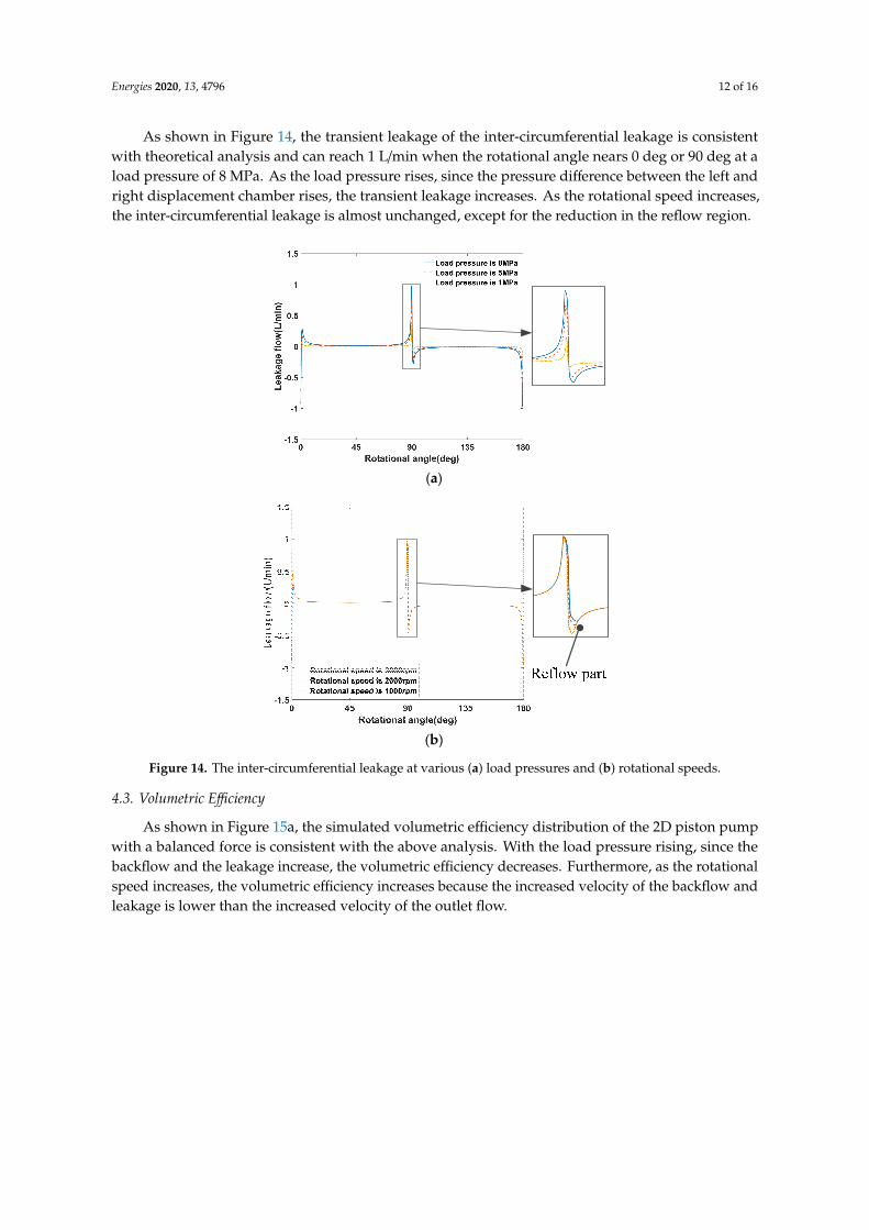
As shown in Figure 14, the transient leakage of the inter-circumferential leakage is consistentwith theoretical analysis and can reach 1 L/min when the rotational angle nears 0 deg or 90 deg at aload pressure of 8 MPa. As the load pressure rises, since the pressure difference between the left andright displacement chamber rises, the transient leakage increases. As the rotational speed increases,the inter-circumferential leakage is almost unchanged, except for the reduction in the reflow region.
Energies 2020, 13, x FOR PEER REVIEW 12 of 16
As shown in Figure 14, the transient leakage of the inter-circumferential leakage is consistent with theoretical analysis and can reach 1 L/min when the rotational angle nears 0 deg or 90 deg at a load pressure of 8 MPa. As the load pressure rises, since the pressure difference between the left and right displacement chamber rises, the transient leakage increases. As the rotational speed increases, the inter-circumferential leakage is almost unchanged, except for the reduction in the reflow region.
(a)
(b)
Figure 14. The inter-circumferential leakage at various (a) load pressures and (b) rotational speeds.
4.3. Volumetric Efficiency
As shown in Figure 15a, the simulated volumetric efficiency distribution of the 2D piston pump with a balanced force is consistent with the above analysis. With the load pressure rising, since the backflow and the leakage increase, the volumetric efficiency decreases. Furthermore, as the rotational speed increases, the volumetric efficiency increases because the increased velocity of the backflow and leakage is lower than the increased velocity of the outlet flow.
In addition, due to wear and manufacturing accuracy, clearances between the piston rings, 2D piston, and cylinder block are easily changed. As shown in Figure 15b, the volumetric efficiency decreases significantly with the increase of the clearance.
Figure 14. The inter-circumferential leakage at various (a) load pressures and (b) rotational speeds.
4.3. Volumetric Efficiency
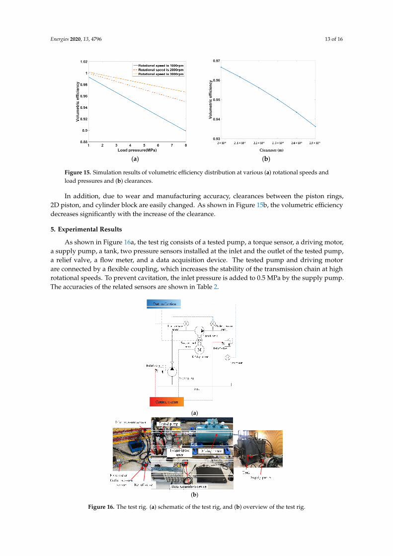
As shown in Figure 15a, the simulated volumetric efficiency distribution of the 2D piston pumpwith a balanced force is consistent with the above analysis. With the load pressure rising, since thebackflow and the leakage increase, the volumetric efficiency decreases. Furthermore, as the rotationalspeed increases, the volumetric efficiency increases because the increased velocity of the backflow andleakage is lower than the increased velocity of the outlet flow.
Energies 2020, 13, 4796 13 of 16Energies 2020, 13, x FOR PEER REVIEW 13 of 16
(a) (b)
Figure 15. Simulation results of volumetric efficiency distribution at various (a) rotational speeds and load pressures and (b) clearances.
5. Experimental Results
As shown in Figure 16a, the test rig consists of a tested pump, a torque sensor, a driving motor, a supply pump, a tank, two pressure sensors installed at the inlet and the outlet of the tested pump, a relief valve, a flow meter, and a data acquisition device. The tested pump and driving motor are connected by a flexible coupling, which increases the stability of the transmission chain at high rotational speeds. To prevent cavitation, the inlet pressure is added to 0.5 MPa by the supply pump. The accuracies of the related sensors are shown in Table 2.
(a)
(b)
Figure 16. The test rig. (a) schematic of the test rig, and (b) overview of the test rig.
Figure 15. Simulation results of volumetric efficiency distribution at various (a) rotational speeds andload pressures and (b) clearances.
In addition, due to wear and manufacturing accuracy, clearances between the piston rings,2D piston, and cylinder block are easily changed. As shown in Figure 15b, the volumetric efficiencydecreases significantly with the increase of the clearance.
5. Experimental Results
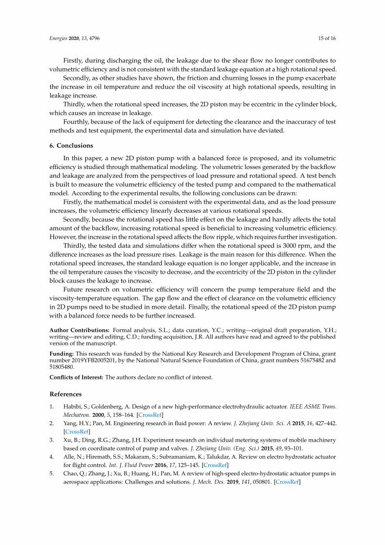
As shown in Figure 16a, the test rig consists of a tested pump, a torque sensor, a driving motor,a supply pump, a tank, two pressure sensors installed at the inlet and the outlet of the tested pump,a relief valve, a flow meter, and a data acquisition device. The tested pump and driving motorare connected by a flexible coupling, which increases the stability of the transmission chain at highrotational speeds. To prevent cavitation, the inlet pressure is added to 0.5 MPa by the supply pump.The accuracies of the related sensors are shown in Table 2.
Energies 2020, 13, x FOR PEER REVIEW 13 of 16
(a) (b)
Figure 15. Simulation results of volumetric efficiency distribution at various (a) rotational speeds and load pressures and (b) clearances.
5. Experimental Results
As shown in Figure 16a, the test rig consists of a tested pump, a torque sensor, a driving motor, a supply pump, a tank, two pressure sensors installed at the inlet and the outlet of the tested pump, a relief valve, a flow meter, and a data acquisition device. The tested pump and driving motor are connected by a flexible coupling, which increases the stability of the transmission chain at high rotational speeds. To prevent cavitation, the inlet pressure is added to 0.5 MPa by the supply pump. The accuracies of the related sensors are shown in Table 2.
(a)
(b)
Figure 16. The test rig. (a) schematic of the test rig, and (b) overview of the test rig.
Figure 16. The test rig. (a) schematic of the test rig, and (b) overview of the test rig.
Energies 2020, 13, 4796 14 of 16
Table 2. The details of the related sensors.
Description Accuracy
Flow meter Range 0–100 L/min, accuracy ± 0.1%Torque/speed sensor Range 0–10 Nm, accuracy ± 0.1%, rotational speed range 0–18,000 rpm
Pressure sensor Range 0–100 bar, accuracy ± 0.3%
The load pressure-flow characteristic data of the tested pump are measured through fixing thespeed of the driving motor and adjusting the relief valve installed at the outlet of the tested pump tocontrol the load pressure. The load pressures, rotational speeds, and outlet flow are recorded, as shownin Table 3.
Table 3. The tested data of the load pressure-flow characteristic.
Rotational Speed Outlet Flow (L/min)
(r/min) 1 MPa 2 MPa 3 MPa 4 MPa 5 MPa 6 MPsa 7 MPa 8 MPa
1000 5.0 4.8 4.7 4.6 4.5 4.4 4.3 4.22000 10.0 9.8 9.7 9.5 9.3 9.3 9.1 9.03000 15.2 15.0 14.8 14.6 14.4 14.3 14.1 13.9
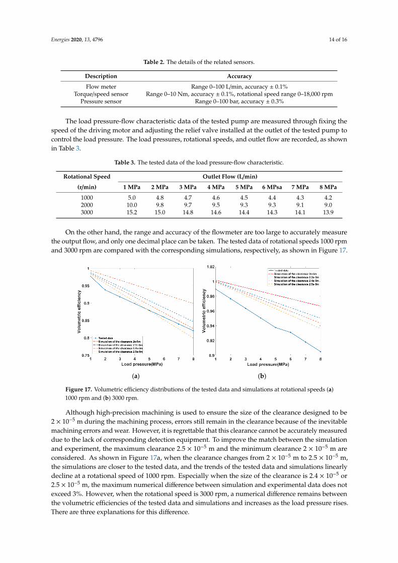
On the other hand, the range and accuracy of the flowmeter are too large to accurately measurethe output flow, and only one decimal place can be taken. The tested data of rotational speeds 1000 rpmand 3000 rpm are compared with the corresponding simulations, respectively, as shown in Figure 17.
Energies 2020, 13, x FOR PEER REVIEW 14 of 16
Table 2. The details of the related sensors.
Description Accuracy Flow meter Range 0–100 L/min, accuracy ± 0.1%
Torque/speed sensor Range 0–10 Nm, accuracy ± 0.1%, rotational speed range 0–18,000 rpm Pressure sensor Range 0–100 bar, accuracy ± 0.3%
The load pressure-flow characteristic data of the tested pump are measured through fixing the speed of the driving motor and adjusting the relief valve installed at the outlet of the tested pump to control the load pressure. The load pressures, rotational speeds, and outlet flow are recorded, as shown in Table 3.
Table 3. The tested data of the load pressure-flow characteristic.
Rotational Speed Outlet Flow (L/min) (r/min) 1 MPa 2 MPa 3 MPa 4 MPa 5 MPa 6 MPsa 7 MPa 8 MPa
1000 5.0 4.8 4.7 4.6 4.5 4.4 4.3 4.2 2000 10.0 9.8 9.7 9.5 9.3 9.3 9.1 9.0 3000 15.2 15.0 14.8 14.6 14.4 14.3 14.1 13.9
On the other hand, the range and accuracy of the flowmeter are too large to accurately measure the output flow, and only one decimal place can be taken. The tested data of rotational speeds 1000 rpm and 3000 rpm are compared with the corresponding simulations, respectively, as shown in Figure 17.
(a) (b)
Figure 17. Volumetric efficiency distributions of the tested data and simulations at rotational speeds (a) 1000 rpm and (b) 3000 rpm.
Although high-precision machining is used to ensure the size of the clearance designed to be 2 × 10⁻⁵ m during the machining process, errors still remain in the clearance because of the inevitable machining errors and wear. However, it is regrettable that this clearance cannot be accurately measured due to the lack of corresponding detection equipment. To improve the match between the simulation and experiment, the maximum clearance 2.5 × 10⁻⁵ m and the minimum clearance 2 × 10⁻⁵ m are considered. As shown in Figure 17a, when the clearance changes from 2 × 10⁻⁵ m to 2.5 × 10⁻⁵ m, the simulations are closer to the tested data, and the trends of the tested data and simulations linearly decline at a rotational speed of 1000 rpm. Especially when the size of the clearance is 2.4 × 10⁻⁵ or 2.5 × 10⁻⁵ m, the maximum numerical difference between simulation and experimental data does not exceed 3%. However, when the rotational speed is 3000 rpm, a numerical difference remains between the volumetric efficiencies of the tested data and simulations and increases as the load pressure rises. There are three explanations for this difference.
Figure 17. Volumetric efficiency distributions of the tested data and simulations at rotational speeds (a)1000 rpm and (b) 3000 rpm.
Although high-precision machining is used to ensure the size of the clearance designed to be2 × 10−5 m during the machining process, errors still remain in the clearance because of the inevitablemachining errors and wear. However, it is regrettable that this clearance cannot be accurately measureddue to the lack of corresponding detection equipment. To improve the match between the simulationand experiment, the maximum clearance 2.5 × 10⁻⁵ m and the minimum clearance 2 × 10⁻⁵ m areconsidered. As shown in Figure 17a, when the clearance changes from 2 × 10⁻⁵ m to 2.5 × 10⁻⁵ m,the simulations are closer to the tested data, and the trends of the tested data and simulations linearlydecline at a rotational speed of 1000 rpm. Especially when the size of the clearance is 2.4 × 10⁻⁵ or2.5 × 10−5 m, the maximum numerical difference between simulation and experimental data does notexceed 3%. However, when the rotational speed is 3000 rpm, a numerical difference remains betweenthe volumetric efficiencies of the tested data and simulations and increases as the load pressure rises.There are three explanations for this difference.
Energies 2020, 13, 4796 15 of 16
Firstly, during discharging the oil, the leakage due to the shear flow no longer contributes tovolumetric efficiency and is not consistent with the standard leakage equation at a high rotational speed.
Secondly, as other studies have shown, the friction and churning losses in the pump exacerbatethe increase in oil temperature and reduce the oil viscosity at high rotational speeds, resulting inleakage increase.
Thirdly, when the rotational speed increases, the 2D piston may be eccentric in the cylinder block,which causes an increase in leakage.
Fourthly, because of the lack of equipment for detecting the clearance and the inaccuracy of testmethods and test equipment, the experimental data and simulation have deviated.
6. Conclusions
In this paper, a new 2D piston pump with a balanced force is proposed, and its volumetricefficiency is studied through mathematical modeling. The volumetric losses generated by the backflowand leakage are analyzed from the perspectives of load pressure and rotational speed. A test benchis built to measure the volumetric efficiency of the tested pump and compared to the mathematicalmodel. According to the experimental results, the following conclusions can be drawn:
Firstly, the mathematical model is consistent with the experimental data, and as the load pressureincreases, the volumetric efficiency linearly decreases at various rotational speeds.
Secondly, because the rotational speed has little effect on the leakage and hardly affects the totalamount of the backflow, increasing rotational speed is beneficial to increasing volumetric efficiency.However, the increase in the rotational speed affects the flow ripple, which requires further investigation.
Thirdly, the tested data and simulations differ when the rotational speed is 3000 rpm, and thedifference increases as the load pressure rises. Leakage is the main reason for this difference. When therotational speed increases, the standard leakage equation is no longer applicable, and the increase inthe oil temperature causes the viscosity to decrease, and the eccentricity of the 2D piston in the cylinderblock causes the leakage to increase.
Future research on volumetric efficiency will concern the pump temperature field and theviscosity-temperature equation. The gap flow and the effect of clearance on the volumetric efficiencyin 2D pumps need to be studied in more detail. Finally, the rotational speed of the 2D piston pumpwith a balanced force needs to be further increased.
Author Contributions: Formal analysis, S.L.; data curation, Y.C.; writing—original draft preparation, Y.H.;writing—review and editing, C.D.; funding acquisition, J.R. All authors have read and agreed to the publishedversion of the manuscript.
Funding: This research was funded by the National Key Research and Development Program of China, grantnumber 2019YFB2005201, by the National Natural Science Foundation of China, grant numbers 51675482 and51805480.
Conflicts of Interest: The authors declare no conflict of interest.
References
1. Habibi, S.; Goldenberg, A. Design of a new high-performance electrohydraulic actuator. IEEE ASME Trans.Mechatron. 2000, 5, 158–164. [CrossRef]
2. Yang, H.Y.; Pan, M. Engineering research in fluid power: A review. J. Zhejiang Univ. Sci. A 2015, 16, 427–442.[CrossRef]
3. Xu, B.; Ding, R.G.; Zhang, J.H. Experiment research on individual metering systems of mobile machinerybased on coordinate control of pump and valves. J. Zhejiang Univ. (Eng. Sci.) 2015, 49, 93–101.
4. Alle, N.; Hiremath, S.S.; Makaram, S.; Subramaniam, K.; Talukdar, A. Review on electro hydrostatic actuatorfor flight control. Int. J. Fluid Power 2016, 17, 125–145. [CrossRef]
5. Chao, Q.; Zhang, J.; Xu, B.; Huang, H.; Pan, M. A review of high-speed electro-hydrostatic actuator pumps inaerospace applications: Challenges and solutions. J. Mech. Des. 2019, 141, 050801. [CrossRef]

Energies 2020, 13, 4796 16 of 16
6. Manring, N.D.; Mehta, V.S.; Nelson, B.E.; Graf, K.J.; Kuehn, J.L. Increasing the Power Density for Axial-PistonSwash-Plate Type Hydrostatic Machines. J. Mech. Des. 2013, 135, 071002. [CrossRef]
7. Crowder, R.M. Electrically powered actuation for civil aircraft. In Proceedings of the IEE Colloquium onActuator Technology: Current Practice and New Developments, London, UK, 10 May 1996.
8. Wu, S.; Yu, B.; Jiao, Z.; Shang, Y.; Luk, P.C.K. Preliminary design and multi-objective optimization ofelectro-hydrostatic actuator. Proc. Inst. Mech. Eng. Part G J. Aerosp. Eng. 2017, 231, 1258–1268. [CrossRef]
9. Manring, N.D.; Mehta, V.S.; Nelson, B.E.; Graf, K.J.; Kuehn, J.L. Scaling the Speed Limitations for Axial-PistonSwash-Plate Type Hydrostatic Machines. J. Dyn. Syst. Meas. Control 2014, 136, 031004. [CrossRef]
10. Manring, N.D. Friction forces within the cylinder bores of swash-plate type axial-piston pumps and motors.J. Dyn. Syst. Meas. Control 1999, 121, 531–537. [CrossRef]
11. Schenk, A.; Ivantysynova, M. An investigation of the impact of elastohydrodynamic deformation on powerloss in the slipper swashplate interface. In Proceedings of the 8th JFPS International Symposium on FluidPower, Okinawa, Japan, 25–28 October 2011; pp. 228–234.
12. Manring, N.D. Tipping the cylinder block of an axial-piston swash-plate type hydrostatic machine. J. Dyn.Syst. Meas. Control 2000, 122, 216–221. [CrossRef]
13. Zhang, J.; Chao, Q.; Xu, B.; Pan, M.; Wang, Q.; Chen, Y. Novel three-piston pump design for a slipper test rig.Appl. Math. Model. 2017, 52, 65–81. [CrossRef]
14. Zhang, J.H.; Chen, Y.; Xu, B.; Pan, M.; Chao, Q. Effects of splined shaft bending rigidity on cylinder tiltbehaviour for high-speed electro-hydrostatic actuator pumps. Chin. J. Aeronaut. 2019, 32, 499–512. [CrossRef]
15. Strmcnik, E.; Majdic, F.; Kalin, M. Water-lubricated behaviour of AISI 440C stainless steel and a DLC coatingfor an orbital hydraulic motor application. Tribol. Int. 2019, 131, 128–136. [CrossRef]
16. Shang, L.; Ivantysynova, M. Port and case flow temperature prediction for axial piston machines. Int. J. FluidPower 2015, 16, 35–51.
17. Zecchi, M.; Mehdizadeh, A.; Ivantysynova, M. A novel approach to predict the steady state temperaturein ports and case of swash plate type axial piston machines. In Proceedings of the 13th ScandinavianInternational Conference on Fluid Power, Linköping, Sweden, 3–5 June 2013; pp. 177–187.
18. Huang, Y.; Ding, C.; Wang, H.; Ruan, J. Numerical and experimental study on the churning losses of 2Dhigh-speed piston pumps. Eng. Appl. Comput. Fluid Mech. 2020, 14, 764–777. [CrossRef]
19. Zhang, J.H.; Li, Y.; Xu, B.; Chen, X.; Pan, M. Churning losses analysis on the thermal-hydraulic model of ahigh-speed electro-hydrostatic actuator pump. Int. J. Heat Mass Transf. 2018, 127, 1023–1030. [CrossRef]
20. Zhang, J.H.; Li, Y.; Xu, B.; Pan, M.; Lv, F. Experimental Study on the Influence of the Rotating Cylinder Blockand Pistons on Churning Losses in Axial Piston Pumps. Energies 2017, 10, 662. [CrossRef]
21. Ruan, J.; Burton, R.; Ukrainetz, P.; Xu, Y.M. Two-dimensional pressure control valve. Proc. Inst. Mech. Eng.Part C J. Mech. Eng. Sci. 2001, 215, 1031–1038. [CrossRef]
22. Ding, C.; Zhu, Y.H.; Liu, L.; Tong, C.W.; Ruan, J. Research on a Novel Flowmeter With ParallelTwo-Dimensional Pistons as Its Metering Units. IEEE Access 2019, 7, 110912–110927. [CrossRef]
23. Shentu, S.; Ruan, J.; Qian, J.; Meng, B.; Wang, L.; Guo, S. Study of flow ripple characteristics in an innovativetwo-dimensional fuel piston pump. J. Braz. Soc. Mech. Sci. Eng. 2019, 41, 464. [CrossRef]
24. Jin, D.C.; Ruan, J.; Li, S.; Meng, B.; Wang, L.F. Modelling and validation of a roller-cam rail mechanism usedin a 2D piston pump. J. Zhejiang Univ. Sci. A 2019, 20, 201–217. [CrossRef]
25. Xing, T.; Xu, Y.; Ruan, J. Two-dimensional Piston Pump: Principle, Design, and Testing for Aviation FuelPumps. Chin. J. Aeronaut. 2019, 33, 1349–1360. [CrossRef]
26. Huang, Y.; Ruan, J.; Zhang, C.; Ding, C.; Li, S. Research on the Mechanical Efficiency of High-Speed 2DPiston Pumps. Processes 2020, 8, 853. [CrossRef]
© 2020 by the authors. Licensee MDPI, Basel, Switzerland. This article is an open accessarticle distributed under the terms and conditions of the Creative Commons Attribution(CC BY) license (http://creativecommons.org/licenses/by/4.0/).