v series axial piston pump
TRANSCRIPT

B
P14
FEATURES:1. Combining special internal designs and strict engineering disciplines has
reduced noise level to new lows in whole pressure zones.2. Depending on variety of application needs multiple optional unique control
methods are available. It does not only reduce a number of unnecessary hoses, pipes and control valves but also increase efficiency and save horsepower, and cost.
3. Less capacity reservoirs can be selected and applied because of performances of low pressure loss and less head generation.
4. Wide application ranges: it is very suitable for machine tools, plastic injection molding machines, forging machines, other industrial machines and so on.
V SERIES AXIAL PISTON PUMP
1 V: Variable displacement type VR: For Axial port-pipe type VR15 VR18 VR23 VR38 (see page 47)
2 Displacement: 15, 18, 23, 25, 38, 42, 50, 70 (cc/rev)
3 Control types: A,B,C,CG,D,DG,E,EG,F,
FG,G,GJ,GM,HL□,HJ,HK□,HQ□
4 Pressure adjusting 1: 8-70 bar 2: 15-140 bar 3: 20-210 bar 4: 20-250 bar
5 Shaft rotation (Viewed from shaft end) R: Clockwise L: Counter clockwise
6 Direction of pipe connections: None: Side port B: Axial port
7
8 Voltage: A: AC 100V (50/60Hz) B: AC 110V (60Hz) C: AC 200V (50/60Hz) D: AC 220V (60Hz) E: DC 12V F: DC 24V
9 Threads Code
10 Thru drive & 2nd pump:
None: Single pump C: SAE AA, ø50.8 mm D: SAE A, ø82.55 mm E: SAE B,ø101.6 mm F: SAE C, ø127 mm I: Metric, ø63 mm J: Metric, ø80 mm K: Metric, ø100 mm L: Metric, ø125 mm
11 Design number: X: Standard X1: Low Pressure Z: Idling Relief
12 Links type (For V15, V18): None: Standard A: SAE A 2 bolt
V - 15 A - 1 - R - B - S - □ - □ - □ - □ - □1 2 3 4 5 6 7 8 9 10 11 12
How to order
Specifications Model
Displacementcc/rev
(in³/rev)
Unloading Conditions (lpm) (GPM)
Pressure Adj.Range
bar (psi)
Max.Pressure bar (psi)
Input Speed Range (rpm) Weight
(kg)1500 rpm 1800 rpm Min. Max.
V15A 15 (0.90) 22.5 (5.78) 27.0 (7.05)
1: 8-70 (115-100)
2: 15-140 (210-2000)
3: 20-210 (280-3000)
4: 20-250 (280-3500)
250 (3500)
500 1800
13
V18A 17.8 (1.09) 26.7 (7.05) 32.0 (8.45) 13
V23A 23.0 (1.40) 35.4 (9.11) 41.4 (10.94) 22
V25A 25.0 (1.52) 37.5 (9.66) 45.0 (11.60) 210 (3000) 22
V38A 37.8 (2.31) 56.7 (14.98) 68.0 (17.96) 250 (3500) 26
V42A 42.0 (2.56) 63.0 (16.23) 76.0 (19.58)
210 (3000)
26
V50A 51.5 (3.14) 77.2 (20.37) 92.7 (4.49) 55
V70A 69.7 (4.25) 104.5 (27.60) 125.4 (33.13) 56
V15A-V15A 15 / 15 22.5 / 22.5 27 / 27
250 (3500)
28.5
V23A-V23A 23.0 / 23.0 35.4 / 35.4 41.4 / 41.4 46.5
V15A-V38A 15 / 37.8 22.5 / 34.5 27 / 68 41.5
V38A-V38A 37.8 / 37.8 56.7 / 56.7 68 / 68 54.5
V15A-V70A 15 / 69.7 22.5 / 104.5 27 / 125.4210 (3000)
71.5
V38A-V70A 37.8 / 69.7 56.7 / 104.5 68 / 125.4 84.5
None: S: SAE. J498b Code Type Number of teeth Pitch
SV15V18
13
16/32 DPS1 9
S2 11
Code Spring
None Standard pressure: 7 bar
B Middle pressure: 14 bar
C High pressure: 21 bar
Code Type Number of teeth Pitch
S V23,V25V38,V42
1316/32 DP
S1 15
S V50V70
1412/24 DP
S1 17
* This spring code is useful for HL, HK, HQ types.
Code Port Threads50 NPT Inch60 SAE (O-ingring) Inch
Code Port Threads10 PT Pipe type40 BSPP (G) Metric
Code Port Threads70 M Metric
B
E
out
INDR

B
P15
Control Types
V SERIES AXIAL PISTON PUMP
B
Control Types JIS Symbols Characteristics Feature
A: Pressure Compensator Control
1. When system pressure increase and reach preset pressure the flow decrease automatically and pressure maintain without changing.
2. Power and pressure can be adjusted manually.
B: Multi-stage Flow & Single stage Pressure Control Type (With Cylinder)
1. Flow can be adjusted from 0 to maximum and pressure can be maintaining at preset pressure.
2. Absorbing impact and vibration which are produced by up and down motions of actuators. It is suitable for lifting equipment etc.
C: 2 stage Pressure & Flow Control Type
1. Low consumption electric motor can be selected to save energy because of the functions of high flow at low pressure and low flow at high pressure.
2. When pressure increase and reach preset pressure "PH", flow is reduced to "QL".
3. Pressure "PH""PL", and Flow "QH""QL" can be adjusted optionally.
4. It is applied to actuators requiring long unloaded or short loaded strokes. Speedy and horsepower efficient.
CG: 2 stage remote Pressure & Flow Control Type
1. The same function of "C" control type.
2. The pressure and the range can be adjusted remotely by the integrated remote pressure control valve.
3. Proportional Electro-hydraulic pressure control can be applied with HYDROME proportional valve.
D: Solenoid Controlled Pressure Compensating Type with Unloading Device
1. Same as type A and unloading function added.
2. It is applied to systems requiring long term unloading operation.
3. When solenoid is turned off, pump operation under unloading condition maintains low noise level and oil heat generation.
DG: Solenoid Controlled Pressure Compensating Type with Unloading & Remote Device
1. The same function of "C" control type.
2. The pressure and the range can be adjusted remotely by the integrated remote pressure control valve.
3. Proportional Electro-hydraulic pressure control can be applied with HYDROME proportional valve.

B
P16
Control Types
B
V SERIES AXIAL PISTON PUMP
Control Types JIS Symbols Characteristics Feature
E: Dual Pressure Control 1. Preset high and low pressure can be controlled by switching directions of solenoid control valves.
2. This type is applied to actuators requiring 2 stage pressures with single speed.
3. One of "PL" and "PH" can be optionally be high pressure.
EG: Dual & Remote Pressure Control
1. The same function of "E" control type.
2. The pressure and the range can be adjusted remotely by the integrated remote pressure control valve.
3. Proportional Electro-hydraulic pressure control can be applied with HYDROME proportional valve.
F: 2 flow-2 pressure p.c.by solenoid operated valve
1. Actuators can be shifted slowly (high pressure low flow) and quickly (low pressure high flow) by switching directions of solenoid control valve. When solenoid valve turns on, pressure increase to "PH", and flow decrease to "QL".
2. Pressure "PL", "PH" and flow "QL", "QH" can be adjusted optionally.
3. This type is applied to actuator requiring operations of shift speed from high to low or low to high.
FG: 2 flow-2 pressure p.c. by solenoid operated & remote valve
1. The same function of "F" control type.
2. The pressure and the range can be adjusted remotely by the integrated remote pressure control valve.
3. Proportional Electro-hydraulic pressure control can be applied with HYDROME proportional valve.
G: Remote pressure compensator control
1. The same function of "A" control type.
2. Pressure can be adjusted remotely by the integrated remote pressure control valve.
GJ: Proportional Pressure with interface
1. Same as Type "GM" and proportional valve added.
2. The proportional valve is installed on the NG 6 interface to reach Proportional Electro-hydraulic control to save energy.

B
P17
Control Types
V SERIES AXIAL PISTON PUMP
Control Types JIS Symbols Characteristics Feature
GM: Remote Interface (Not include pilot valve)
1. GM control with a NG6 interface, supply an installation for pilot valve to prove the operating pressure. The pressure setting can be set directly from the control panel of the machine.
2. The remote pressure compensator responds faster and offers more stable pressure.
3. The adjustment can also be manual or proportional pressure control.
HL: Load Sensing Compensator
1. The pump outlet can be controlled by the setting pressure value of flow control valve. An ideal energy conservation system can be configurated by combining the proportional directional control.
2. When setting pressure value, flow is changed depending on throttle valve. The sensing flow feedback function can reach to low oil heat generation and saving energy.
HJ: Load Sensing & Proportronal Electro-hydraulic Pilot Relief Valve
1. Same as Type "HL" and proportional pressure function added.
2. Supplied with proportional Electro-hydraulic pilot relief valve can reach to horse-saving and energy-saving.
HK: Proportional Electro- hydrauic Load Sensing Type
1. HK type supplies the system pressure and flow depending on the proportional pressure and flow, voltage, and load value to save the energy. When in waiting circle, the outlet displacement and horse power loss are colse to zero. When pressure reaches to preset value, the flow decrease to the min., and the pressure is constant to reach low oil heat generation and energy loss.
2. HK type can save 30%~50% energy compare to vane pump and gear pump+PQ valve. It is an energy-saving and environmental design.
HQ: Load-sensing Proportional Flow control
1. Same as Type "HL" and proportional flow function added.
2. The proportional flow control allows the adjustment of the pumps output flow with an electrical input signal. Supplied and adjusted the displacement by the electronic control module.

B
P18
Performance curves
MEASURING CONDITIONSROOM TEMPERATURE:20±2°C
SPEED OF ROTATION:1800 rpm
OIL:ISO VG 32-68
OIL CAPACITY:40 lpm
ADOPTS SEALED CIRCUIT:70 bar
ADJUST PRESSURE:35 bar
V23, 25 Series
V15, 18 Series
V50 Series
V38, 42 Series
V70 Series
V SERIES AXIAL PISTON PUMP

B
P19
Performance curves
V15, 18 V23, 25
V38, 42 V50, 70
V15, 18 V23, 25
V38, 42 V50, 70
V SERIES AXIAL PISTON PUMP

B
P20
Dimensions
V15A, V18A Pressure Compensator (SAE A 2 bolt)
V15B, V18B Multi-stage Flow & Single-stage PressureCompensator Control (With cylinder)
V15A, V18A Pressure Compensator
V SERIES AXIAL PISTON PUMP

B
P21
Dimensions
V15CG, V18CG 2-stage Pressure & Flow Control Type with Remote
V15D, V18D Solenoid Controlled Pressure CompensatingType with Unloading Device
V15C, V18C 2-stage Pressure & Flow Control Type
V SERIES AXIAL PISTON PUMP

B
P22
Dimensions
V15E, V18E Dual Pressure Control
V15EG, V18EG Dual & Remote Pressure Control
V SERIES AXIAL PISTON PUMP
V15DG, V18DG Solenoid Controlled Pressure CompensatingType with Unloading Device & Remote

B
P23
Dimensions
V SERIES AXIAL PISTON PUMP
V15FG, V18FG 2 Flow-2 Pressure Control by Solenoid Operated & Remote Valve
V15G, V18G Remoted Pressure Compensator Control
V15F, V18F 2 Flow-2 Pressure Control by Solenoid Operated Valve

B
P24
Dimensions
V15GM, V18GM Remote Interface (Not include valve)
V15HL, V18HL Load-sensing Compensator
V SERIES AXIAL PISTON PUMP
V15GJ, V18GJ Proportional Pressure with Interface

B
P25
Dimensions
V15HQ, V18HQ Load-sensing Proportional Flow Control
V15, V18 Splined Shaft Type V15, V18 Hydraulic Flange
V15HK, V18HK Proportional Electro-hydraulic Load Sensing Type
V SERIES AXIAL PISTON PUMP

B
P26
Dimensions
Type A B C CG D DG E EG F FG G GJ GM HL HK HQ
O O O O O O O O O O OThru Drive Option
Type A B C CG D DG E EG F FG G GJ GM HL HK HQ
O O O O O O O O O O OThru Drive Option
V15, V18 Prepared for Thru Drive (SAE Aø82.55)
V15, V18 Prepared for Thru Drive (SAE AAø50.8)
V SERIES AXIAL PISTON PUMP

B
P27
Dimensions
V SERIES AXIAL PISTON PUMP
V23B, V25B Multi-stage Flow & Single-stage PressureCompensator Control (With Cylinder)
V23C, V25C 2-stage Pressure & Flow Control Type
V23A, V25A Pressure Compensator

B
P28
Dimensions
V SERIES AXIAL PISTON PUMP
V23D, V25D Solenoid Controlled Pressure Compensating Typewith Unloading Device
V23DG, V25DG Solenoid Controlled Pressure Compensating Typewith Unloading Device & Remote
V23CG, V25CG 2-stage Pressure & Flow Control Type with Remote

B
P29
Dimensions
V23EG, V25EG Dual & Remote Pressure Control
V23F, V25F 2 Flow-2 Pressure Control by Solenoid Operated Valve
V23E, V25E Dual Pressure Control
V SERIES AXIAL PISTON PUMP

B
P30
Dimensions
V23G, V25G Remoted Pressure Compensator Control
V23GJ, V25GJ Proportional Pressure with interface
V23FG, V25FG 2 Flow-2 Pressure Control by Solenoid Operated & Remote Valve
V SERIES AXIAL PISTON PUMP

B
P31
Dimensions
V23HL, V25HL Load-Sensing Compensator
V23HK, V25HK Proportional Electro-hydraulic Load Sensing Type
V23GM, V25GM Remoted Interface (Not include valve)
V SERIES AXIAL PISTON PUMP

B
P32
Dimensions
V23, V25 Prepared for Thru Drive (SAE Aø82.55)
V23, V25 Prepared for Thru Drive (SAE Bø101.6)
V23HQ, V25HQ Load-Sensing Proportional Flow Control
V SERIES AXIAL PISTON PUMP
Type A B C CG D DG E EG F FG G GJ GM HL HK HQO O O O O O O O O O O
Thru Drive Option
B
P33
Dimensions
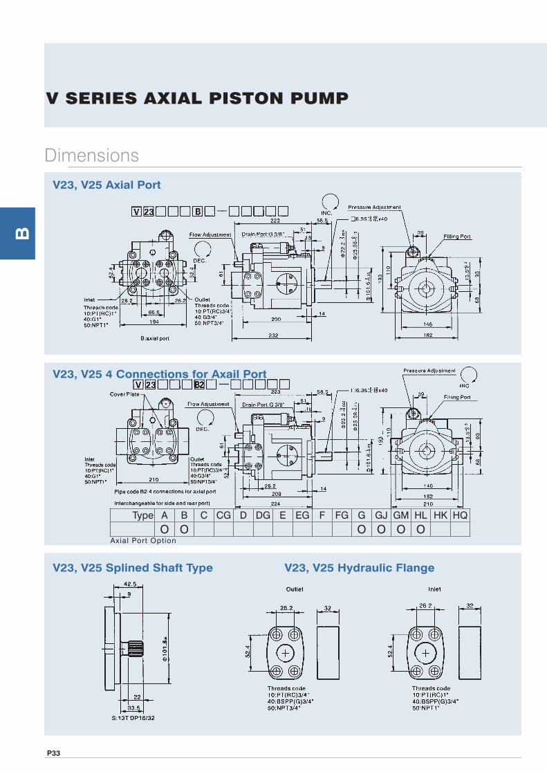
V23, V25 4 Connections for Axail Port
V23, V25 Splined Shaft Type V23, V25 Hydraulic Flange
V23, V25 Axial Port
V SERIES AXIAL PISTON PUMP
Type A B C CG D DG E EG F FG G GJ GM HL HK HQO O O O O O
Axial Port Option

B
P34
Dimensions
V38B, V42B Multi-stage Flow & Single-stage PressureCompensator Control (With cylinder)
V38C, V42C 2-stage Pressure & Flow Control Type
V38A, V42A Pressure Compensator
V SERIES AXIAL PISTON PUMP

B
P35
Dimensions
V38D, V42D Solenoid Controlled Pressure Compensating Typewith Unloading Device
V38DG, V42DG Solenoid Controlled Pressure Compensating Typewith Unloading Device & Remote
V38CG, V42CG 2-stage Pressure & Flow Control Type with Remote
V SERIES AXIAL PISTON PUMP

B
P36
Dimensions
V38EG, V42EG Dual & Remote Pressure Control
V38F, V42F Flow-2 Pressure Control by Solenoid Operated Valve
V38E, V42E Dual Pressure Control
V SERIES AXIAL PISTON PUMP

B
P37
Dimensions
V38G, V42G Remoted Pressure Compensator Control
V38GJ, V42GJ Proportional Pressure with Interface
V38FG, V42FG 2 Flow-2 Pressure Control by Solenoid Operated & Remote Valve
V SERIES AXIAL PISTON PUMP

B
P38
Dimensions
V38HL, V42HL Load-sensing Compensator
V38HK, V42HK Proportional Electro-hydraulic Load Sensing Type
V38GM, V42GM Remote Interface (Not include valve)
V SERIES AXIAL PISTON PUMP

B
P39
Dimensions
V38, V42 Prepared for Thru Drive (SAE Aø82.55)
V38, V42 Prepared for Thru Drive (SAE Bø101.6)
V38HQ, V42HQ Load-sensing Proportional Flow Control
V SERIES AXIAL PISTON PUMP
Type A B C CG D DG E EG F FG G GJ GM HL HK HQO O O O O O O O O O O
Thru Drive Option

B
P40
Dimensions
V38, V42 4 Connections for Axial Port
V38, V42 Splined Shaft Type V38, V42 Hydraulic Flange
V38, V42 Axial Port
V SERIES AXIAL PISTON PUMP
Type A B C CG D DG E EG F FG G GJ GM HL HK HQ
O O O O O O O O O OAxial Port Option

B
P41
Dimensions
V50B, V70B Multi-stage Flow & Single-stage PressureCompensator Control (With cylinder)
V50C, V70C 2-stage Pressure & Flow Control Type
V50A, V70A Pressure Compensator
V SERIES AXIAL PISTON PUMP

B
P42
Dimensions
V50F, V70F 2 Flow-2 Pressure Control by Solenoid Operated Valve
V50G, V70G Remoted Pressure Compensator Control
V50D, V70D Solenoid Controlled Pressure Compensating Type with Unloading Device
V SERIES AXIAL PISTON PUMP

B
P43
Dimensions
V50GM, V70GM Remote Interface (Not include valve)
V50HL, V70HL Load-sensing Compensator
V50GJ, V70GJ Proportional Pressure with interface
V SERIES AXIAL PISTON PUMP

B
P44
Dimensions
V50HQ, V70HQ Load-Sensing Proportional Flow Control
V50, V70 Splined Shaft Type V50, V70 Hydraulic Flange
V50HK, V70HK Proportional Electro-hydraulic Load Sensing Type
V SERIES AXIAL PISTON PUMP
Outlet Inlet

B
P45
V SERIES AXIAL PISTON PUMP
Dimensions
V50, V70 Axial Port
V50, V70 Prepared for Thru Drive (SAE Aø82.55, SAE Bø101.6)
Type A B C CG D DG E EG F FG G GJ GM HL HK HQ
O O O O O O O O O O OThru Drive Option
Type A B C D F G GJ GM HL HK HQ
O O O O O O O O OAxial Port Option

B
P46
V SERIES AXIAL PISTON PUMP
No. Description No. Description No. Description No. Description
1 Bolt 18 Shaft Key 35 M snap ring 52 Valve plate
2 Port plug 19 Bearing of shaft 36 Plug 53 Snap ring
3 Pressure compensator 20 Bearing of shaft 37 Bolt 54 Washer cylinder block
4 O-ring 21 Servo spring washer 38 Flange 55 Retainer spring
5 Gasket 22 Servo spring 39 O-ring 56 Washer cylinder block
6 Lock nut 23 End cover seal 40 Bolt 57 Cylinder block
7 O-ring 24 Pump body 41 Roller 58 Roller
8 Control compensator shaft 25 Drain plug 42 Roller 59 Cylinder block holder
9 Spring washer 26 Filling screw 43 End cover 60 Slipper retainer
10 Control spring 27 O-ring 44 Roller 61 Pistons
11 O-ring washer 28 O-ring 45 O-ring 62 Piston head
12 O-ring 29 Swash shaft 46 Flange 63 Flow screw
13 Lock nut 30 Bolt 47 Bolt 64 O-ring
14 Screw 31 Bolt 48 Plug 65 Sleeve piston
15 Slipper plate 32 Swash shaft 49 Washer cylinder block 66 Servo piston sleeve
16 Swash 33 O-ring 50 Bearing of pump cover
17 Shaft 34 Shaft seal 51 Bearing of pump cover
Decomposition Chart
List of parts

B
P47
VR SERIES AXIAL PISTON PUMP
Dimensions
VR23A※※B-※Axial Port (Pipe type)
VR38A※※B-※Axial Port (Pipe type)
VR15A※※B-※Axial Port

B
P48
V SERIES TANDEM AXIAL PISTON PUMP
Pump 1 V15(V18) V23(V25) V23(V25) V38(V42) V38(V42) V38(V42) V50(V70) V50(V70) V50(V70)
Pump 2 V15(V18) V15(V18) V23(V25) V15(V18) V23(V25) V38(V42) V15(V18) V23(V25) V38(V42)A G 3/8" G 3/8" G 3/8" G 3/8" G 3/8" G 1/2" G 3/8" G 3/8" G 1/2"
B G 3/8" G 3/8" G 3/8" G 1/2" G 1/2" G 1/2" G 3/4" G 3/4" G 3/4"
C 57.45 57.45 61 57.45 61 73 57.45 61 73
D 35.1 35.1 52.4 35.1 52.4 58.7 35.1 52.4 58.7
E 35.1 35.1 26.2 35.1 26.2 30.2 35.1 26.2 30.2
F 35.1 52.4 52.4 58.7 58.7 58.7 69.9 69.9 69.9
G 35.1 26.2 26.2 30.2 30.2 30.2 35.7 35.7 35.7
H M8×20 M8×20 M10×16 M8×20 M10×16 M10×16 M8×20 M10×16 M10×16
I M8×20 M10×16 M10×16 M10×16 M10×16 M10×16 M12×25 M12×25 M12×25
J 147 147 170 147 170 179 147 170 179
K 147 170 170 179 179 179 256.5 256.5 256.5
L 332 369 402 378 401 410 464 493 502
M 382 419 455 428 454 465 515 546 555
N 48 48 51 48 51 51 48 51 51
O 48 51 51 51 51 51 73 73 73
P 6 9 9 9 9 9 10 10 10
Q 4.76×32 6.35×40 6.35×40 6.35×40 6.35×40 6.35×40 7.94×45 7.94×45 7.94×45
R 13 14 14 14.5 14.5 14.5 24 24 24
S ø19.05 ø22.22 ø22.22 ø22.22 ø22.22 ø22.22 ø31.75 ø31.75 ø31.75
T 21.15 25.08 25.08 25.08 25.08 25.08 35.35 35.35 35.35
U ø82.55 ø101.6 ø101.6 ø101.6 ø101.6 ø101.6 ø127 ø127 ø127
V ø25 ø25 ø25 ø31 ø31 ø31 ø38 ø38 ø38
W ø25 ø25 ø25 ø31 ø31 ø31 ø38 ø38 ø38
X 106 146 146 146 146 146 181 181 181
Y 131 146 146 160 160 160 208 208 208
Z 165 182 182 198.6 198.6 198.6 261.5 261.5 261.5
A1 44 39 39 39 39 39 74 74 74
A2 31.2 31.2 31.2 31.2 31.2 31.2 40 40 40
A3 5 5 5 5 5 5 8 8 8
A4 84 110 110 121 121 121 119 119 119
A5 11 13.5 13.5 13.5 13.5 13.5 18 18 18
A6 44.5 58.5 58.5 58.5 58.5 58.5 57 57 57
A7 160 193 193 210 210 210 233.5 233.5 233.5
A8 91.5 93 93 113.5 113.5 113.5 133.5 133.5 133.5
A9 60 68 68 72 72 72 100 100 100
Tandem pump (Multi-option for tandem pump)

B
P49
AR Control Type (see page. 15,16,17) 01: Pressure Compensator G: Remote Pressure CompensatorGJ: Layer Porportional Pressure CompensatorGR: Electrical UnloadingGB: Dual Pressure ControlGC: Dual Pressure+Electrical UnloadingGM: Remote Pressure Compensator allows a pilot valveH L : Load-sensing Compensator
AR SERIES AXIAL PISTON PUMP
Model
F R 01 C S K 10 Y
Mounting Direction of Rotation
Control Type
Pres. Adj. Range bar
(MPa)Port
PositionShaft
ExtensionThreads
Code Design
AR16(15.8cc/rev)
F: Flange Mtg.
Viewed from Shaft End * R: Clockwise (Standard) L: Counter Clockwise
01: Pressure Compensator Type HL: Load Sensing Compensator G: Remote Pressure Compensator
B:12~70 (1.2~7) C:12~210
(1.2~21)
None: Axial Port S: Side Port
*K: Keyed G: 16/32 DP-13T T: 16/32 DP-9T
*10: PT(RC) theard 40: BSPP(G) theard 50: NPT theard
X *Y
AR22(22.2cc/rev)
Y-Type
AR-16
AR-22
※StandardOrdering Codes
E
out
INDR

B
P50
AR SERIES AXIAL PISTON PUMP
Decomposition Chart
Model
F R 01 C S K 10 Y
Mounting Direction of Rotation
Control Type
Pres. Adj. Range bar
(MPa)Port
PositionShaft
ExtensionThreads
Code Design
AR16(15.8cc/rev)
F: Flange Mtg.
Viewed from Shaft End * R: Clockwise (Standard) L: Counter Clockwise
01: Pressure Compensator Type HL: Load Sensing Compensator G: Remote Pressure Compensator
B:12~70 (1.2~7) C:12~210
(1.2~21)
None: Axial Port S: Side Port
*K: Keyed G: 16/32 DP-13T T: 16/32 DP-9T
*10: PT(RC) theard 40: BSPP(G) theard 50: NPT theard
X *Y
AR22(22.2cc/rev)
No. Description No. Description No. Description No. Description
1 Pump body 18 C snap ring 1-1/2 36 Slipper retainer 58 Control compensator shaft
2 Swash 19 1715 bearing rear 37 Piston 61 Flange 506A (6”)
3 Swash shaft 20 Shaft seal 37A Head of piston 62 O-ring G30
4 Swash plate 21 Screw M10x40L 38 Cylinder block 63 Pipe plug 1/2
5 Body seal 22 R62 snap ring 39 Valve plate 64 Pipe plug 3/4
6 Servo piston sleeve 23 Plug, feeder 40 Snap ring for bore R28 65 NPT 1/16
7 Servo spring washer 25 Key 41 Washer cylinder block 66 Screw M8x35
8 Swash spring 26 Locator pin, body 42 Retainer spring 67 Screw M10x35
9 Pump body / end cover 27 Locator pin, cradle 51 Screw M10x30 68 Lock nut M8
10 Sleeve piston 28 Locator pin, ø6x12.8 52 Lock nut M10 69 Body seal
11 Flow bar 29 O-ring P8 70˚ 53 Control lock nut 70 Plastic plug 3/4
12 Seal 30 O-ring P7 54 O-ring P14 70˚ 71 Plastic plug 3/8
15 Valve 32 O-ring S11 55 Control washer 72-73 Name Plate
16 Screw M5x25L 34 Cylinder block holder 56 Control spring 74-75 Description label
17 6305 bearing front 35 Roller 57 Spring washer
List of parts

B
P51
FEATURES 1. New type of swash plate and large servo pistons with
strong bias spring achieve fast response, reduce the noise due to active decompression of system at down stroke.
2. Nine piston and new precompression technology (precompression filter volume) result in unbeaten low outlet flow pulsation.
3. Rigid and FEM-optimized body design for lowest noise level.
4. Thru drive for 100% nominal torque.5. Pump combinations (tandem pumps) of same size and
model and mounting interface for basically all metric or SAE mounting interfaces.
PV SERIES AXIAL PISTON PUMP
Continuous: 350barIntermittent: 420bar
Quick Reference Data Chart
ModelDisplacement
Pump Delivery (7 bar) 100 PSI
1200 RPM 1500 RPM 1800 RPM
cc/rev In3/rev LPM U.S. GPM LPM U.S. GPM LPM U.S. GPM
PV016 16 0.98 19.2 5.1 24 6.3 28.8 7.6
PV020 20 1.2 24 6.3 30 7.9 36 9.5
PV023 23 1.4 27.6 7.3 34.5 9.1 41.4 10.9
PV032 32 19 38.4 10.1 48 12.7 57.6 15.2
PV040 40 2.4 48 12.7 60 15.9 72 19
PV046 46 2.8 55.2 14.6 69 18.2 82.8 21.9
PV063 63 3.8 75.6 20 94.5 25 113.4 30
PV071 71 4.3 85.8 22.7 107 28.3 128.7 34
PV080 80 4.8 96 25.4 120 31.7 144 38
PV092 92 5.6 110.4 29.2 138 36.5 165.6 43.8
PV140 140 8.5 168 44.4 210 55.5 252.1 66.6
PV180 180 11 216 57.1 270 71.3 324 85.6
PV270 270 16.5 324 85.6 405 107 486 128.4
Model
APPROX. Noise Levels Db(A) Full Flow and 1500 RPM
Input Horse Power, Max. Displacement &
345 bar (5000PSI)Operating Speed Weight
(kg)
70 bar(1 KPSI)
207 bar(3 KPSI)
343 bar(5 KPSI)
1500 rpm 1800 rpm Max. Min.KW(hp) KW(hp) RPM RPM kg lb
PV016
56 60 68
15.5 (20.8) 18.5 (24.8)
2750
300
19 41.8PV020 19.5 (26.1) 23.4 (31.4)
PV023 22.5 (30.2) 25.1 (33.6)
PV032
59 62 69
31 (41.6) 35.1 (47.1)
2400 30 66PV040 39 (52.3) 46.5 (62.3)
PV046 45 (60.3) 50.2 (67.3)
PV063
66 70 74
61.5 (82.4) 70.1 (94) 2100
60 132PV071 70 (93.8) 80 (107.2) 2100
PV080 78 (104.6) 89.2 (119.6) 2000
PV092 89.5 (120) 136.8 (183.4) 1900
PV140 70 74 76 136 (182.3) 149.4 (200.3) 2200 90 198
PV180 71 75 77 175 (235) 210 (282) 2200 90 198
PV270 77 79 81 263 (353) 298 (400) 1800 172 378.4
1. Installation outlet port top, the pipe have to less than 2 bar.2. The use of max. pressure override 6 min, hydraulic oil clean that see General Installation Information.3. Hydrome offer tandem pumps, and other pumps connection, the connection type use metric version and SAE version dimensions.
E
out
INDR

B
P52
PV SERIES AXIAL PISTON PUMP
How to order
1 Series Axial piston pump variable displacement high pressure version
2 Size and Displacement
3 Control Types
4 Rotation (Viewed from shaft end)
Code Displacement cc/rev (In3/rev)016 16 (0.98)020 20 (1.2)023 23 (1.4)032 32 (1.9)040 40 (2.4)
Code Compensator※ Standard Type Pressure Compensator
A2 10~140 barA3 40~210 barA4 70~350 barRemote Type
※ GT Remote pressure compensator※ GM Remote pressure compensator allows a pilot valve
GA Remote pressure compensator allows a pilot valve (valve included)
GJ Layer proportional pressure compensator (valve included)
Electrical Unloading TypeGR Electrical unloadingGB Dual pressure controlGC Dual pressure+electrical unloadingLoad-sensing Type
※ HL Load-sensing typeHM Load-sensing type
PV - 063 - GT - R - M - 1 - A - ※ - ※ - ※1 2 3 4 5 6 7 8 9 10
Code Rotation※ R clockwise
L counterclockwise
CodeHorse power
PV016~ PV032~ PV063~ PV140 PV180 PV270PV023 PV046 PV092
A 3 KW ●
B 4 KW ●
C 5.5 KW ● ●
D 7.5 KW ● ●
E 11 KW ● ● ●
F 15 KW ● ●
G 18.5 KW ● ● ●
H 22 KW ● ● ● ●
I 30 KW ● ● ●
J 37 KW ● ● ● ●
K 45 KW ● ● ● ●
L 55 KW ● ● ●
M 75 KW ● ●
N 90 KW ● ●
O 110 KW ●
P 132 KW ●
HJ 2-valve load-sensing type (valve included)HA 2-valve load-sensing typeHK Proportional electro-hydraulic load sensing typeHQ Load-sensing & Proportional flow controlProportionable displacement TypeFV Proportionable displacement controlFR Proportionable displacement control with pressure
FG Proportionable displacement control with pressurecontrol
Horse Power Type
PA□ Horse power compensator
※ PM□Horse power compensator, pilot flow internal pressure pilot valve (valve included)
PG□ Horse power compensator, pilot flow internal
PL□ Horse power compensator, load-sensing compensator
PH□Horse power compensator, pilot flow external forload-sensing
Code Displacement cc/rev (In3/rev)046 46 (2.8)063 63 (3.8)071 71 (4.3)080 80 (4.8)092 92 (5.6)
Code Displacement cc/rev (In3/rev)140 140 (8.5)180 180 (10.9)270 270 (16.5)

B
P53
5 Mounting
6 Threads
PV SERIES AXIAL PISTON PUMP
How to order PV - 063 - GT - R - M - 1 - A - ※ - ※ - ※
1 2 3 4 5 6 7 8 9 10
Code Mounting※ M (standard)
MetricISO 3019/2 Cylindric, key
K ISO 3019/2 Splined, DIN5480
Code MountingN
InchISO 3019/1 Cylindric, key
D ISO 3019/1 Splined, SAE
Code Threads※ 1 (standard) BSPP (G)
2 PT (RC)3 UNF4 NPT7 ISO 6149
Code Model Shaft Flange Mounting
A B C D E
※ M Metric
PV016~PV023 ø25 8×7×40 ø100 9 ø125PV032~PV046 ø32 10×8×56 ø125 9 ø160PV063~PV092 ø40 12×8×80 ø160 9 ø200PV140~PV180 ø50 12×8×80 ø160 9 ø200PV270 ø65 12×8×80 ø200 9 ø250
K Metric
PV016~PV023 W25×1.5×15×8f DIN5480 ø100 9 ø125PV032~PV046 W32×1.5×20×8f DIN5480 ø125 9 ø160PV063~PV092 W40×1.5×25×8f DIN5480 ø160 9 ø200PV140~PV180 W50×2×24×9g DIN5480 ø160 9 ø200PV270 W60×2×28×9g DIN5480 ø200 9 ø250
N Inch
PV016~PV023 ø1" 0.25"×0.25"×1.6" ø4" 3/8" ø5"PV032~PV046 ø1-1/4" 5/16"×5/16"×2.2" ø5" 1/2" ø6.37"PV063~PV092 ø1-3/4" 7/16"×7/16"×3.15" ø6" 1/2" ø9"PV140~PV180 ø2" 1/2"×1/2"×2.95" ø6" 1/2" ø9"PV270 ø2" 1/2"×1/2"×2.95" ø6.5" 5/8" ø12.5"
D Inch
PV016~PV023 Splined 15T 16/32DP ANSI B92.1 ø4" 3/8" ø5"PV032~PV046 Splined 14T 12/24DP ANSI B92.1 ø5" 1/2" ø6.37"PV063~PV092 Splined 13T 8/16DP ANSI B92.1 ø6" 1/2" ø9"PV140~PV180 Splined 15T 8/16DP ANSI B92.1 ø6" 1/2" ø9"PV270 Splined 15T 8/16DP ANSI B92.1 ø6.5" 5/8" ø12.5"

B
P54
7 Thru drive & 2nd pump
8 Voltage
9 Seals
10 Design No. Not require for order
CouplingCode pump HA-D1
PV016~PV023
D1 9T 20/40 DPA-D2 D2 9T 16/32 DPA-D3 D3 13T 16/32 DPA-D4 D4 15T 16/32 DPA-W1 W1 W25×1.5×15×8fB-D2
PV032~PV046
D2 9T 16/32 DPB-D3 D3 13T 16/32 DPB-D4 D4 15T 16/32 DPB-D5 D5 14T 12/24 DPB-W1 W1 W25×1.5×15×8fB-W2 W2 W32×1.5×20×8fC-D2
PV063~PV092
D2 9T 16/32 DPC-D3 D3 13T 16/32 DPC-D4 D4 15T 16/32 DP
CouplingCode pump HC-D5
PV063~PV092
D5 14T 12/24 DPC-D6 D6 13T 8/16 DPC-D7 D7 15T 8/16 DPC-W1 W1 W25×1.5×15×8fC-W2 W2 W32×1.5×20×8fC-W3 W3 W40×1.5×25×8fC-W4 W4 W50×2×24×9gD-D2
PV140~PV180
D2 9T 16/32 DPD-D3 D3 13T 16/32 DPD-D4 D4 15T 16/32 DPD-D5 D5 14T 12/24 DPD-D6 D6 13T 8/16 DPD-D7 D7 15T 8/16 DPD-W1 W1 W25×1.5×15×8f
CouplingCode pump HD-W2
PV140~PV180
W2 W32×1.5×20×8fD-W3 W3 W40×1.5×25×8fD-W4 W4 W50×2×24×9gE-D2
PV270
D2 9T 16/32 DPE-D3 D3 13T 16/32 DPE-D4 D4 15T 16/32 DPE-D5 D5 14T 12/24 DPE-D6 D6 13T 8/16 DPE-D7 D7 15T 8/16 DPE-W1 W1 W25×1.5×15×8fE-W2 W2 W32×1.5×20×8fE-W3 W3 W40×1.5×25×8fE-W4 W4 W50×2×24×9gE-W5 W5 W60×2×28×9g
PV SERIES AXIAL PISTON PUMP
PV - 063 - GT - R - M - 1 - A - ※-※-※1 2 3 4 5 6 7 8 9 10
Code Voltage0 NoneA AC100V (50-60Hz)B AC110V (60Hz)
Code VoltageF DC24V
Code VoltageC AC200V (50-60Hz)D AC220V (60Hz)E DC12V
Code Seals※ N NBR
V FPM
Code SealsE Ethylen-propylen
Code Model øA øC D E F G H
C
Inch
SAE AA, ø2" (ø50.8mm) ø2" (ø50.8) 3.25" (82.55mm) 5/16"-18 9T 20/40 DP
D SAE A, ø3-1/4" (ø82.55mm) ø3-1/4" (ø82.55) 4.188" (106.3mm) 3/8"-16 9T 16/32 DPE SAE B, ø4" (ø101.6mm) ø4" (ø101.6) 3.536" (89.8mm) 1/2"-13 5.75" (146.05mm) 1/2"-13 13T 16/32 DP, 15T 16/32 DP F SAE C, ø5" (ø127mm) ø5" (ø127) 4.508" (114.5mm) 1/2"-13 7.125" (180.98mm) 5/8"-11 14T 12/24 DP, 15T 16/32 DPG SAE D, ø6" (ø152.4mm) ø6" (ø152.4) 6.364" (161.6mm) 5/8"-11 9" (228.6mm) 5/8"-11 13T 8/16 DP, 15T 8/16 DPH SAE E, ø6.5" (ø165.1mm) ø6.5" (ø165.1) 8.839" (224.5mm) 3/4"-10 15T 8/16 DPI
Metric
Metric, ø63 ø63 ø85 M8 100 M8J Metric, ø80 ø180 ø103 M8 109 M10K Metric, ø100 ø100 ø125 M10 150 M12 W25×1.5×15×8fL Metric, ø125 ø125 ø160 M12 180 M16 W32×1.5×20×8fM Metric, ø160 ø160 ø200 M16 224 M20 W40×1.5×25×8f , W50×2×24×9gN Metric, ø200 ø200 ø250 M20 W50×2×24×9g
Code Thru drive & 2nd pump
※ A (standard) Single pump
※ B Prepared for thru driveWith adaptor for 2nd pumpC
Inch
SAE AA, ø2" (ø50.8mm)D SAE A, ø3-1/4" (ø82.55mm)E SAE B, ø4" (ø101.6mm)F SAE C, ø5" (ø127mm)G SAE D, ø6" (ø152.4mm)H SAE E, ø6.5" (ø165.1mm)I
Metric
Metric, ø63J Metric, ø80K Metric, ø100L Metric, ø125M Metric, ø160N Metric, ø200Other pump are acceptable order
How to order

B
P55
Compensator
PV SERIES AXIAL PISTON PUMP
Standard Type
A: Standard pressure compensator remote typeGT: Remote pressure compensatorGM: Remote pressure compensator allows a pilot valveGA: Remote pressure compensator allows a pilot valve (valve included)GJ: Layer proportional pressure compensator (valve included)
Electrical Unloading Type
GR: Electrical unloadingGB: 2 pressure electrical selectionGC: 2 pressure + electrical unloading
Load-sensing TypeHL: Load-sensing compensatorHM: Load-sensing compensatorHJ: 2-vavle load-sensing compensatorHA: 2-vavle load-sensing compensator (valve included)HK: Proportional electro-hydraulic load sensing typeHQ: Load-sensing & Proportional flow control
Horse Power Type
PA: Horse power compensatorPM: Horse power compensator, pilot flow internal pressure pilot valve includedPG: Horse power compensator, pilot flow internalPL: Horse power compensator, Load-sensing compensatorPH: Horse power compensator, pilot flow external for load-sensing
A: Standard Pressure compensator The standard pressure compensator adjusts the pump displacement
according to the actual need of the system in order to keep the pressure constant. As long as the system pressure at outlet port P is lower than the set pressure (set as spring preload of the compensator spring) the working port A of the compensator valve is connected to the case drain and the piston area is unloaded. Bias spring and system pressure on the annulus area keep the pump at full displacement.
GT: Remote Pressure compensator
When the system pressure reaches the set pressure the compensator valve spool connects port P1 to A and builds up a pressure at the servo piston resulting in a down stroking of the pump. The displacement of the pump is controlled in order to match the flow requirement of the system.
While at the standard pressure compensator the pressure is set directly at the compensator spring, the setting of the remote pressure compensator can be achieved by any suitable pilot pressure valve connected to pilot port PP. The pilot flow supply is internal through the valve spool.
The pilot flow is 1-1.5 lpm. The pilot valve can be installed remote from the pump in some distance. That allows pressure setting e.g. from the control panel of the machine. The remote pressure compensator and is able to solve instability problems that may occur with a standard pressure compensator in critical applications. The pressure pilot valve can also be electronically controlled (proportional pressure valve) or combined with a directional control valve for low pressure standby operation.

B
P56
GA: Remote Pressure compensator allows a pilot valve (valve included)
GJ: Layer Proportional pressure compensator (valve included)
Remote Pressure compensator allows pilot valveVersion GM of remote pressure compensator provides on its top side an interface NG6, DIN24340 (CETOP 03 at RP35H, NFPA D03). This interface allows a direct mounting of a pilot valve. Beside manual or electro hydraulic operated valves it is also possible to mount complete multiple pressure circuits directly on the compensator body. HYDROME
PV SERIES AXIAL PISTON PUMP
Compensator
GM: Remote Pressure compensator allows a pilot valve
offers a variety of these compensator accessories ready to install. All remote pressure compensator have a factory setting of 15 bar differential pressure. With this setting, the controlled pressure at the pump outlet is higher than the pressure controlled by the pilot valve.

B
P57
Compensator
PV SERIES AXIAL PISTON PUMP
Electrical Unloading Type
PV pump with fast response remote pressure control, relief valve with 2 pressure stages, electrical pressure selection, nitrile seals, spindle adjustment, 24 VDC solenoid, plug to DIN46350 accessories fitted.Usable for horsepower control and proportional volume control, too.
GR: Electrical unloading type
GB: Dual pressure control
GC: Dual pressure + electrical unloading

B
P58
HM: Load-sensing compensator
HJ: 2-valve load-sensing compensator
Load-sensing TypeHL: Load-sensing compensator
PV SERIES AXIAL PISTON PUMP
Compensator
The load-sensing compensator has an external pilot pressure supply. Factory setting for the differential pressure is 10 bar. The input signal to the compensator is the differential pressure at a main stream resistor. A load-sensing compensator represents mainly a flow control for the pump output flow, because the compensator keeps
the pressure drop at the main stream resistor constant. A variable input speed or a varying load (pressure) has consequently no influence on the output flow of the pump and speed of the actuator. By adding a pilot orifice (ø0.8mm) and compensation can be added to the flow control function. See the circuit diagram below, left.
Shown above is load sensing compensator code HM with an NG6 interface on top of the control valve. That allows direct mounting of a pilot valve for pressure compensation. This version includes the pilot orifice. Due to the interaction of flow and pressure compensation
this package has not the “ideal” control characteristic. The deviation is caused by the pilot valves characteristic.
If a more accurate pressure compensation is required, the 2-valve load-sensing compensator code HJ can be used. The circuit diagram of this version is shown left. Here the interaction of the two control
functions is avoided by using two separate control valves for flow and pressure compensation. The 2-valve compensator is equipped with an interface NG6 on the compensators top side.

B
P59
Compensator
PV SERIES AXIAL PISTON PUMP
HA: 2-valve load-sensing compensator (valve included)
The hydraulic-mechanical horse power compensator consists of a modified remote pressure compensator (Code PG*、PM*) or of a modified load-sensing compensator (Code PH*) and a pilot valve. This pilot valve is integrated into the pump and is adjusted by a cam sleeve. The cam sleeve has a contour that is designed and machined for the individual displacement and the nominal horse power setting.At a large displacement the opening pressure (given by the cam sleeve diameter) is lower than at small displacements. This makes the pump compensate along a constant horse power (torque) curve.
PM: Horse power compensator, pilot flow internal pressure pilot valve included
PA: Horse power compensator
For all nominal powers of standard electrical motors HYDROME offers a dedicated cam sleeve. The exchange of this cam sleeve (e. g. : to change horse power setting) can easily be done without disassembly of the pump.On top of that an adjustment of the horse power setting can be done within certain limits by adjustment the preload of the pilot control cartridge spring. That allows an adjustment of a constant horse power setting for other than the nominal speeds (1500min-1) or for other horse power.

B
P60
PL: Horse power compensator, Load-sensing compensator
PH: Horse power compensator, pilot flow external for load-sensing
PG: Horse power compensator, pilot flow internal
PV SERIES AXIAL PISTON PUMP
Compensator

B
P61
PV SERIES AXIAL PISTON PUMP
Performance curves
Horse Power Compensator, diagrams
The diagrams shown are only valid for the following working conditions:speed:n=1500(- -)and 1800(─)rev/mintemperature:t=50℃
fluid:mineral oil HLP, ISO VG46viscosity:v=46mm/s at 40℃
Flo
w -
lp
m (
GP
M)
Pressure - bar (PSI)
Pressure - bar (PSI)
Pressure - bar (PSI)
Pressure - bar (PSI)
Pressure - bar (PSI)
Pressure - bar (PSI)
Flo
w -
lp
m (
GP
M)
Flo
w -
lp
m (
GP
M)
Flo
w -
lp
m (
GP
M)
Flo
w -
lp
m (
GP
M)
Flo
w -
lp
m (
GP
M)

B
P62
PV SERIES AXIAL PISTON PUMP
Performance curves
Efficiency And Case Drain FlowsPV016-PV023The efficiency and power graphs are measured at an input speed of n = 1500 min-1, a temperature of 40˚C and a fluid viscosity of 46 mm2/s.Case drain flow and compensator control flow leave via the drain port of the pump. To the valves shown are to be added 1 to 1.2 lpm, if at pilot operated compensator (code G*, H* horse power compensator and P/Q-control) the control flow of the pressure pilot valve also goes
through the pump.Please note: The valves shown below are only valid for static operation. Under dynamic conditions and at rapid compensator of the pump the volume displaced by the servo piston also leaves the case drain port.This dynamic control flow can reach up to 40 lpm.Therefore the case drain line is to lead to the reservoir at full size and without restrictions at short and direct as possible.

B
P63
Performance curves
Efficiency And Case Drain FlowsPV032-PV046The efficiency and power graphs are measured at an input speed of n = 1500 min-1, a temperature of 40°C and a fluid viscosity of 46 mm2/s.Case drain flow and compensator control flow leave via the drain port of the pump. To the valves shown are to be added 1 to 1.2 lpm, if at pilot operated compensator (code G*,H* horse power compensator and P/Q-control) the control flow of the pressure pilot valve also goes
through the pump.Please note: The valves shown below are only valid for static operation. Under dynamic conditions and at rapid compensator of the pump the volume displaced by the servo piston also leaves the case drain port.This dynamic control flow can reach up to 60 lpm.Therefore the case drain line is to lead to the reservoir at full size and without restrictions at short and direct as possible.
PV SERIES AXIAL PISTON PUMP

B
P64
Performance curves
Efficiency And Case Drain FlowsPV063, PV080, PV092The efficiency and power graphs are measured at an input speed of n = 1500 min-1, a temperature of 40°C and a fluid viscosity of 46 mm2/s.Case drain flow and compensator control flow leave via the drain port of the pump. To the valves shown are to be added 1 to 1.2 lpm, if at pilot operated compensator (code G*, H* horse power compensator and P/Q-control) the control flow of the pressure pilot valve also goes
through the pump.Please note: The valves shown below are only valid for static operation. Under dynamic conditions and at rapid compensator of the pump the volume displaced by the servo piston also leaves the case drain port.This dynamic control flow can reach up to 80 lpm.Therefore the case drain line is to lead to the reservoir at full size and without restrictions at short and direct as possible.
PV SERIES AXIAL PISTON PUMP

B
P65
PV SERIES AXIAL PISTON PUMP
Performance curves
Efficiency And Case Drain FlowsPV140, PV180The efficiency and power graphs are measured at an input speed of n = 1500 min-1, a temperature of 40°C and a fluid viscosity of 46 mm2/s.Case drain flow and compensator control flow leave via the drain port of the pump. To the valves shown are to be added 1 to 1.2 lpm, if at pilot operated compensator (code G*, H* horse power compensator and P/Q-control) the control flow of the pressure pilot valve also goes
through the pump.Please note: The valves shown below are only valid for static operation. Under dynamic conditions and at rapid compensator of the pump the volume displaced by the servo piston also leaves the case drain port.This dynamic control flow can reach up to 120 lpm.Therefore the case drain line is to lead to the reservoir at full size and without restrictions at short and direct as possible.

B
P66
PV SERIES AXIAL PISTON PUMP
Performance curves
Pump Accessories
Straight SAE connection GFS
Bell housing, coupling and foot flange
Welding flange, Threaded flange
SAE-flange connections, pipeconnection in accordance toDIN-2353
Elbow SAE-flange conncetion WFS
Efficiency And Case Drain FlowsPV270The efficiency and power graphs are measured at an input speed of n = 1500 min-1, a temperature of 40°C and a fluid viscosity of 46 mm2/s.Case drain flow and compensator control flow leave via the drain port of the pump. To the valves shown are to be added 1 to 1.2 lpm, if at pilot operated compensator (code G*, H* horse power compensator and P/Q-control) the control flow of the pressure pilot valve also goes
through the pump.Please note: The valves shown below are only valid for static operation. Under dynamic conditions and at rapid compensator of the pump the volume displaced by the servo piston also leaves the case drain port.This dynamic control flow can reach up to 120 lpm.Therefore the case drain line is to lead to the reservoir at full size and without restrictions at short and direct as possible.

B
P67
PV016~PV023
PV SERIES AXIAL PISTON PUMP
PV016~PV023 DimensionsMounting øA øB C D øE F H
M (standard) Metric ISO 3019/2 Splined, DIN 5480 ø25 ø100 h8 8x7x40 9 125 12 52
N Inch ISO3019/2 Cylindric, key ø25.4 (1") ø101.6 (4") 6.35x6.35x40 (1/4") 9.4 (0.37") 127 (5") 12 (0.47") 50 (1.97")
Mounting Shaft øB D øE F H
K (standard) Metric ISO 3019/2 Cylindric, key
Splined W25x1.5x15x8fDIN 5480 ø100 h8 9 125 12 43
D Inch ISO 3019/1 Splined, SAE
Splined 15T 16/32 DP, flat root, side fit ANSI B92.1 ø101.6 (4") 9.4 (0.37") 127 (5") 12 (0.47") 46 (1.81")
Dimensions
Mounting: M,N
Mounting: K,D

B
P68
PV032~PV046 DimensionsMounting øA øB C D øE F H
M (standard) Metric ISO 3019/2 Splined, DIN 5480 ø32 ø125 h8 10x8x56 9 160 14 68
N Inch ISO 3019/2 Cylindric, key ø31.75 (1.25") ø127 (5") 7.94x7.94x56
(5/16") 12.7 (0.5") 161.93 (6.38") 14 (0.55") 68 (2.68")
Mounting Shaft øB D øE F H
K (standard) Metric ISO 3019/2 Cylindric, key
Splined W32x1.5x20x8f DIN 5480 ø125 h8 9 160 14 47
D Inch ISO 3019/1 Splined, SAE
Splined 14T 12/24 DP, flat root, side fit ANSI B92.1 ø127 (5") 12.7 (0.5") 161.93 (6.38") 14 (0.55") 56 (2.31")
D1 Inch ISO 3019/1 Splined, SAE
Splined 15T 16/32 DP, flat root, side fit ANSI B92.1 ø127 (5") 12.7 (0.5") 161.93 (6.38") 14 (0.55") 56 (2.31")
PV032~PV046
PV SERIES AXIAL PISTON PUMP
Dimensions
Mounting: M,N
Mounting: K,D

B
P69
PV SERIES AXIAL PISTON PUMP
PV063~PV092
PV063~PV092 DimensionsMounting øA øB C D øE F H
M (standard) Metric ISO 3019/2 Splined, DIN 5480 ø40 ø160 h8 12x8x80 9 200 18 92
N Inch ISO 3019/2 Cylindric, key
ø44.45(1.75") ø152.4 (6") 11.11x11.11x80
(7/16") 12.7 (0.5") 228.6 (9") 20.6 (0.81") 90 (3.54")
Mounting Shaft øB D øE F H
K (standard) Metric ISO 3019/2 Cylindric, key
Splined W40x1.5x25x8f DIN 5480 ø160 h8 9 200 18 56
D Inch ISO 3019/1 Splined, SAE
Splined 15T 16/32 DP, flat root, side fit ANSI B92.1 ø152.4 (6") 12.7 (0.5") 228.6 (9") 20.6 (0.81") 75 (2.95")
Dimensions
Mounting: M,N
Mounting: K,D

B
P70
PV SERIES AXIAL PISTON PUMP
Dimensions
PV140~PV180 DimensionsMounting øA øB C D øE F H
M (standard) Metric ISO 3019/2 Splined, DIN 5480 ø50 ø160 h8 14x9x75 9 200 18 92
N Inch ISO 3019/2 Cylindric, key ø50.8 (2") ø152.4 (6") 12.7x12.7x75
(1/2") 12.7 (0.5") 228.6 (9") 20.6 (0.81") 99.4 (3.91")
F Inch ISO 3019/2 Splined, DIN 5480 ø44.45 ø152.4 (6") 11.11x11.11 12.7 (0.5") 228.6 (9") 20.6 (0.81") 75 (2.95")
Mounting Shaft øB D øE F H
H (standard) Metric ISO 3019/2 Cylindric, key
Splined W50x2x24x8f DIN 5480 ø160 h8 9 200 18 78
D Inch ISO 3019/1 Splined, SAE
Splined 15T 8/16 DP, flat root, side fit ANSI B92.1 ø152.4 (6") 12.7 (0.5") 228.6 (9") 20.6 (0.81") 88 (3.46")
G Inch ISO 3019/1 Splined, SAE
Splined 13T 8/16 DP, flat root, side fit ANSI B92.1 ø152.4 (6") 12.7 (0.5") 228.6 (9") 20.6 (0.81") 75 (2.95")
PV140~PV180
mounting hole for horse powercompensator pilot or displacementfeedback LVDT
drain port L2:G1/2 optional M22 1.5;ISO 6149-1(threads options 7) or 7/8-14 UNF (threads options 3)
gage port M:G1/4 optional M12 1.5;ISO 6149-1(threads options 7) or 7/16-20 UNF (threads options 3)
drain port L2:G1/2 optional M22 1.5;ISO 6149-1(threads options 7) or 7/8-14 UNF (threads options 3)
gage port M:G1/4 optional M12 1.5;ISO 6149-1(threads options 7) or 7/16-20 UNF (threads options 3)
Outlet:flange according ISO 6162DN 19;PN 400 bar
4 M12, 20 deepoptional 1/2-13 UNC-2B(threads options 3 and 7)
flushing port L3; G 3/4optional M27 2;ISO 6149-1(threads options 7) or 1 1/16-12UNF (threads options 3)
Inlet:flange according ISO 6162DN 32;PN 250 bar
4 M12, 20 deepoptional 1/2-13 UNC-2B(threads options 3 and 7)
Shown with standard pressure compensator
Mounting: M,N
mounting hole for horse powercompensator pilot or displacementfeedback LVDT
Mounting: K,D

B
P71
PV SERIES AXIAL PISTON PUMP
Dimensions
PV270
PV270 DimensionsMounting øA øB C D øE F H
M (standard) Metric ISO 3019/2 Splined, DIN 5480 ø65 ø200 h8 18x11x98 9 250 22 115
N Inch ISO 3019/2 Cylindric, key ø50.8 (2") ø165.1 (6.5") 12.7x12.7x75
(1/2") 15.9 (0.37") 317.5 (12.5") 20.6 (0.81") 97.5 (3.84")
Mounting Shaft øB D øE F H
K (standard) Metric ISO 3019/2 Cylindric, key
Splined W60x2x28x8f DIN 5480 ø200 h8 9 250 22 80
D Inch ISO 3019/1 Splined, SAE
Splined 15T 8/16 DP, flat root, side fit ANSI B92.1 ø165.1 (6.5") 15.9 (0.37") 317.5 (12.5") 20.6 (0.81") 88(3.46")
Mounting: M,N
Mounting: K,D

B
P72
PV SERIES AXIAL PISTON PUMP
Important noticeThe max. allowable torque of the individual shaft must notbe exceeded. For 2-pump combinations there is no problembecause PV series offers 100% thru torque. For 3-pumpcombinations (and more) the limit torque could be reachedor exceeded.Therefore it is necessary to calculate the torque factor andcompare it with the allowed torque limit factor in the table.
Required: calculated torque factor <torque limit factor
To make the necessary calculations easier and more userfriendly it is not required to calculate actual torque requirementsin Nm and compare them with the shaft limitations. The tableon the right shows limit factors that include material specification,safety factors and conversion factors.
The total torque factor is represented by the sumof the individual torque factors of all pumps in thecomplete pump combination.
The torque factor of each individual pump is calculated bymultiplying the max. operating pressure p of the pump(in bar) with the max. displacement Vg of the pump (in cc/rev)
The max. transferable torque in Nm for the different shafts options are:
Shaft code PV16~23 PV32~46 PV63~92 PV140~180 PV270
N 300 550 1320 2000 2000
D 300 610 1218 2680 2680
F - - - 1320 -
G - - - 1640 -
M 300 570 1150 1900 2850
K 405 675 1400 2650 3980
Pump Shaft Torque limit factor
PV016~
PV023
N 17700
D 17700
M 17700
K 20130
PV032~
PV046
N 32680
D 36380
M 33810
K 40250
PV063~
PV092
N 77280
D 72450
M 67620
K 83720
PV140~
PV180
N 118400
D 158760
F 78750
G 97650
M 113400
K 157500
PV270
N 119000
D 159700
M 170100
K 236250
Total torque factor of the comination=
sum of individual torque factors of all pumps
Torque factor of any pump=P x Vg
(Pressure in bar x displacement in cc/rev)
Thru drive, shaft load limitations

B
P73
PV SERIES AXIAL PISTON PUMP
Decomposition Chart
No. Description Quantity No. Description Quantity No. Description Quantity No. Description Quantity
1 Head cap screw 4 23 Pin 2 46 Washer 1 68 Piston nut 12 Pilot cover 1 24 Screw 4 47 Snap ring 1 69 Screw 13 O-ring 1 25 Trunnion bearing 2 48 Valve plate 1 70 Trunnion bearing 14 Shaft seal 1 26 Screw 2 49 Pin 1 71 Plug 15 Snap ring 1 27 Name plate 1 50 Seal 1 72 Pin 16 Snap ring 1 28 Rivet 2 51 Seal 1 73 Spring 17 Washer 1 29 O-ring 1 52 Pin 1 74 Ball 18 Washer 1 30 Plug 1 53 Pump body 2 75 O-ring 29 Roller bearing 1 31 Chain link 1 54 O-ring 1 76 Label 110 Roller bearing 1 32 Chain link 1 55 O-ring 1 77 Seal 111 Roller bearing 1 33 Chain link 1 56 Plug 1 78 Plug 1
12 Key 1 34 Connector servo spring 1 57 O-ring 1 79 O-ring 1
13 Shaft 1 35 Swash plate 1 58 Label 1 80 Washer 114 Pump body 1 36 Piston 9 59 O-ring 1 81 Spring 115 O-ring 1 37 Piston 9 60 Servo pistion sleeve 1 82 O-ring 116 Plug 1 38 Slipper segment 1 61 O-ring 1 83 O-ring 117 Plug 1 39 Washer 4 62 O-ring 1 84 Pin 118 Ring 1 40 Retainer segment 2 63 Servo piston 1 85 O-ring 119 Plug 1 41 Screw 4 64 Set screw 1 86 Screw 120 O-ring 1 43 Cylinder block 1 65 O-ring 1 87 O-ring 121 O-ring 1 44 Washer 1 66 Servo spring cover 1 88 Spring cover 122 Cradle 1 45 Spring 1 67 Washer 1
List of parts

B
P74
1.Fluid recommendationsPremium quality hydraulic mineral oil fluids are recommended, like H-LP oils to DIN 51524, part 2. The viscosity range should be 25 to 50 mm2/(cst) at 50°C. Operating temperatures -10 to +70°C. For other fluids such as phosphoric acid esters or for, other operating conditions consult HYDROME for assistance.
2.SealsNBR (Nitrile) seals are used for operation with hydraulic fluids based on mineral oil. For synthetic, as perhaps phosphoric acid esters, Fluorocarbon seals are required. Consult HYDROME for assistance.
3.FiltrationFor maximum pump and system component functionability and life, the system should be protected from contamination by effective filtration. Fluid cleanness should be in accordance with ISO classification ISO The quality of filter elements should be in accordance with ISO
(1) Minimum requiremenet for filtration rate x (um): General hydraulic systems for satisfactory operation: Class 19/15, to ISO 4406. X=25 μm(ß10≥75) to ISO 4572
(2) Hydraulic systems with maximized component life and functionability: Class 16/13, to ISO 4406. X=10 μm(ß10≥75) to ISO 4572
It is recommended to use return line or pressure filters. HYDROME Filter Division offers a wide range of these filters for all common applications and mounting styles. The use of suction filters should be avoided, especially with fast response pumps. Bypass filtration is a good choice for best filter efficiency.
4.Installation and mountingHorizontal mounting: Outlet port side or top. Inlet port side or bottom, drain port always uppermost.Vertical mounting: Shaft pointing upwards.Install pump and suction line in such a way that the maximum inlet vacuum never exceeds 0.8 bar absolute.The inlet line should be as short and as straight as possible. A short suction line cut to 45° is recommended when the pump is mounted inside the reservoir, to improve the inlet conditions. All connections to be leadfree, as air in the suction line will cause cavitations, noise, and damage to the pump.
5.Shaft rotation and alignmentPump and motor shafts must be aligned within 0.25mm T.I.R. maximum. A floating coupling must be used.Bell housings and couplings can be ordered at manufacturers listed in this catalogue. Please follow the coupling manufacturer's installation instructions.Consult HYDROME for assistance on radial load type drives.
6.Start upPrior to start up, the pump case must be filled with hydraulic fluid (use case drain port). Initial start up should be at zero pressure with an open circuit to enable the pump to prime. Pressure should only be increased once the pump has been fully primed.Attention: Check motor rotation direction.Operating noise of pumpsThe normal operating noise of a pump and consequently the operating noise of the entire hydraulic system is largely determined by where and how the pump is mounted and how it is connected to the down stream hydraulic system. Also size, style and installation of the hydraulic tubing have a major influence on the overall noise emitted by a hydraulic system.
Noise reduction measuresFlexible elements help to prevent pump body vibration being transmitted to other construction elements, where possible amplification may occur, Such elements can be:Bell housing with elastic dampening flange with vulcanized labyrinth ①
(1)Floating and flexible coupling ②
(2)Damping rails ③
(3)Or silent blocks for mounting the electric motor or the foot mounting flange
(4)Flexible tube connections (compensators) or hoses on inlet, outlet and drain port of the pump.
(5)Exclusive use of gas tight tube fittings for inlet connections to avoid ingression of air causing cavitations and excessive noise.
7.Drain lineThe drain line must lead directly to the reservoir without restriction. The drain line must not be connected to any other return line. The end of the drain line must be below the lowest fluid level in the reservoir and as far away as possible from the pump inlet line. This ensures that the pump does not empty itself when not in operation and that hot aireated oil will not be recirculated. For the same reason, when the pump is mounted inside the reservoir, the drain line should be arranged in such a way that a siphon is created. This ensures that the according to the port size and a straight low pressure fitting with maximized bore should be used.
PV SERIES AXIAL PISTON PUMP
No. Description Quantity No. Description Quantity No. Description Quantity No. Description Quantity
1 Head cap screw 4 23 Pin 2 46 Washer 1 68 Piston nut 12 Pilot cover 1 24 Screw 4 47 Snap ring 1 69 Screw 13 O-ring 1 25 Trunnion bearing 2 48 Valve plate 1 70 Trunnion bearing 14 Shaft seal 1 26 Screw 2 49 Pin 1 71 Plug 15 Snap ring 1 27 Name plate 1 50 Seal 1 72 Pin 16 Snap ring 1 28 Rivet 2 51 Seal 1 73 Spring 17 Washer 1 29 O-ring 1 52 Pin 1 74 Ball 18 Washer 1 30 Plug 1 53 Pump body 2 75 O-ring 29 Roller bearing 1 31 Chain link 1 54 O-ring 1 76 Label 110 Roller bearing 1 32 Chain link 1 55 O-ring 1 77 Seal 111 Roller bearing 1 33 Chain link 1 56 Plug 1 78 Plug 1
12 Key 1 34 Connector servo spring 1 57 O-ring 1 79 O-ring 1
13 Shaft 1 35 Swash plate 1 58 Label 1 80 Washer 114 Pump body 1 36 Piston 9 59 O-ring 1 81 Spring 115 O-ring 1 37 Piston 9 60 Servo pistion sleeve 1 82 O-ring 116 Plug 1 38 Slipper segment 1 61 O-ring 1 83 O-ring 117 Plug 1 39 Washer 4 62 O-ring 1 84 Pin 118 Ring 1 40 Retainer segment 2 63 Servo piston 1 85 O-ring 119 Plug 1 41 Screw 4 64 Set screw 1 86 Screw 120 O-ring 1 43 Cylinder block 1 65 O-ring 1 87 O-ring 121 O-ring 1 44 Washer 1 66 Servo spring cover 1 88 Spring cover 122 Cradle 1 45 Spring 1 67 Washer 1
General installation information
PV016~PV023 PV032~PV046 PV063~PV092 PV140~PV180 PV270
Size of pipe joints 3/8 (ø8.5 or more) 1/2 (ø12 or more) 3/4 (ø16 or more) 1 (ø19 or more) 1-1/4 (ø22 or more)
I.D. of pipes ø12 or more ø15 or more ø19 or more ø25 or more ø32 or more
Length of drain Under 1m Under 1m Under 1m Under 1m Under 1m
s
4406.standards.
①②
③

B
P75
Dimensions
PV SERIES TANDEM AXIAL PISTON PUMP
Pump Combination PV
Main pump Second pump Interface main pump L B C D H K M
PV16, 20, 23 PV16, 20, 23 100 B4 HW 489 196 170.5 225 220 225 212
PV32, 40, 46 PV16, 20, 23PV32, 40, 46 125 B4 HW 541
574208208
197197
235.5261
245245
261261
212245
PV63, 80, 92PV16, 20, 23PV32, 40, 46PV63, 80, 92
160 B4 HW630663724
232232232
252252252
244.5271326
299299299
326326326
212245306
PV140, 180
PV16, 20, 23PV32, 40, 46PV63, 80, 92PV140, 180
160 B4 HW
719752813878
230230230230
305305305305
280.5307362415
349349349349
415415415415
212245306385
PV270
PV16, 20, 23PV32, 40, 46PV63, 80, 92PV140, 180PV270
200 B4 HW
860893954
10331134
255255255255255
403403403403403
299325.5380.5433.5531.5
406406406406406
531.5531.5531.5531.5531.5
212245306385510
Combination PV140/180+PV140/180 and PV270+PV270 only with splined shaft on main pump due to high torque
PV pump with thru drive
No. Description
1 Connector
2 Coupling
3 Seal
4 Seal
5 Coupling
List of parts
1 3 2
4
5
ModelDisplacement
cc/revUnloading Conditions (lpm) Pressure Adj.
Rangebar
Max .Pressure
bar
Input Speed Range (rpm) Weight
(kg)1200 rpm 1500 rpm 1800 rpm Min. Max.
PVS-0B-8 8 9.6 12 14.4 0: 20-40
1: 20-73
2: 30-145
3: 30-215
255
500
2000
9
PVS-1B-16 16.5 19.8 24.7 29.7 12
PVS-1B-22 22 26.4 33 39.6 12
PVS-2B-35 36 43.2 54 64.8 23
PVS-2B-45 46 55.2 69 82.8 23
PZS-3B-70 70 84 105 126 1: 20-73
3: 30-215
4: 30-286
286 180041
PZS-4B-100 100 120 150 180 60

B
P76
PVS, PZS SERIES VARIABLE VOLUME PISTON PUMP
B
E
out
INDR
1 PVS: Pump size 0, 1, 2 PZS: Pump size 3, 4
2 Pump sizes: 0: 8 cc/rev 1: 16, 22 cc/rev 2: 36, 46 cc/rev 3: 70 cc/rev 4: 100 cc/rev
3 Mounting Type: B: Flange type (normal) A: Foot type
4 Displacement: 8, 16.5, 22, 36, 46, 70, 100 cc/rev
5 Control types standard type: N Option type: P, NQ, RS (RA), WS (WA), HL
6 Pressure adjusting PVS 0: 20-40 bar 1: 20-73 bar 2: 30-145 bar 3: 30-215 bar PZS 1: 20-73 bar 3: 30-215 bar 4: 30-286 bar
7 Shaft rotation (viewed from shaft end) R: Clockwise L: Counter clockwise
8 Shaft type none: Cylindric, key S: Splined, SAE
ModelDisplacement
cc/revUnloading Conditions (lpm) Pressure Adj.
Rangebar
Max .Pressure
bar
Input Speed Range (rpm) Weight
(kg)1200 rpm 1500 rpm 1800 rpm Min. Max.
PVS-0B-8 8 9.6 12 14.4 0: 20-40
1: 20-73
2: 30-145
3: 30-215
255
500
2000
9
PVS-1B-16 16.5 19.8 24.7 29.7 12
PVS-1B-22 22 26.4 33 39.6 12
PVS-2B-35 36 43.2 54 64.8 23
PVS-2B-45 46 55.2 69 82.8 23
PZS-3B-70 70 84 105 126 1: 20-73
3: 30-215
4: 30-286
286 180041
PZS-4B-100 100 120 150 180 60
PVS - 1 B - 16 N 2 - R - ※ 1 2 3 4 5 6 7 8
Specifications
PVS-0B-8N
Dimensions
How to order

B
P77
Type External View JIS Symbols Characteristics Description
N
Pressure Compensating Type (Manual)
1. When the pressure reaches the value set with the compensator, the flow is reduced automatically and the set pressure is maintained.
2. The pressure and flow are controlled manually.
P
Remote Pressure Control Type
1. The pressure can be controlled according to the pilot pressure.
2. The flow can be controlled manually.
NQ
Two Pressure-Two Flow Control Type
1. By means of the sequence valve, two stage flow rate can be obtained and each flow rate has the different pressure eventually enabling energy savings.
RS(RA)
Solenoid Cut-Off Control Type
1. An unloading solenoid valve is used to minimize the lost energy when the pump output is not required.
2. Heat generated is very small.
WS(WA)
Two Pressure Cut-Off Control Type
1. By means of "ON" "OFF" control of solenoid valves, two different pressure compensating types can be obtained.
HL
Load Sensing Control1. The "HL" compensator is used for load sensing
circuits and is a true load sensor. This is the "P" compensator with a pin in the compensator spool. The pin prevents pilot flow from entering the circuit which will eliminate creeping of the load.
2. The "HL" compensator will let the pump deliver a constant flow rate to the circuit by providing an adjustable ∆P across the customers orifice or valve. The pump will operate at 17.2~27.5 bar (250-400 psi) above "Load pressure".
PVS, PZS SERIES VARIABLE VOLUME PISTON PUMP
Control Types

B
P78
PVS, PZS SERIES VARIABLE VOLUME PISTON PUMP
PVS-1B-16N, PVS-1B-22N
PVS-2B-35N, PVS-2B-45N
Dimensions

B
P79
PZS-3B-70N
PZS-4B-100N
PVS, PZS SERIES VARIABLE VOLUME PISTON PUMP
Dimensions

B
P80
PVS, PZS SERIES VARIABLE VOLUME PISTON PUMP PVS, PZS SERIES VARIABLE VOLUME PISTON PUMP
Cross section drawing
Parts list
PVS-0B-08
PVS-3B-70PVS-4B-100
PVS-1B-16/22PVS-2B-35/45
N0. Part Name N0. Part Name N0. Part Name N0. Part Name N0. Part Name
1 Bady 9 Barrel holder 17 Guide 25 Oil seal 33 Expander plug
2 Case 10 Swash plate 18 Needle 26 Snap ring 34 Machine screw
3 Shaft 11 Thrust bush 19 Key 27 Snap ring 35 Machine screw
4 Cylinder barrel 12 Seal holder 20 Nut 28 Snap ring 36 Flow adj. screw
5 Valve plate 13 Gasket 21 Retainer 29 O-ring 37 Spring Holder
6 Piston 14 Spring 22 Plug 30 O-ring
7 Shoe 15 Spring 23 Ball bearing 31 O-ring
8 Shoe holder 16 Control Piston 24 Needle bearing 32 Pin