swing piston pump - knf
TRANSCRIPT

NPK012TRANSLATION OF ORIGINAL OPERATING ANDINSTALLATION INSTRUCTIONENGLISCH
KNF 316780-316783 12/20 EN-US
OEM
Notice!Before operating the pump and the accessories, read the operating and installation instructions and observethe safety notices!
SWING PISTON PUMP

Contents1 About this document ......................................................... 32 Use ................................................................................... 63 Safety................................................................................ 74 Technical data .................................................................. 95 Design and function ........................................................ 116 Transport ........................................................................ 137 Installation and connection ............................................. 148 Operation ........................................................................ 219 Cleaning.......................................................................... 2510 Troubleshooting .............................................................. 2611 Accessories .................................................................... 2812 Returns ........................................................................... 29
KNF Neuberger GmbHAlter Weg 379112 FreiburgGermanyTel. +49 (0)7664/5909-0Fax. +49 (0)7664/5909-99
www.knf.com

Swing piston pump NPK012 About this document
Translation of original operating and installation instruction, Englisch, KNF 316780-316783 12/20 3
1 About this document
1.1 Using the operating and installation instructionsThe operating and installation instructions are part of the pump.
à In the event of uncertainties with regard to the content of the operatingand installation instructions, please contact the manufacturer (contactdata: see www.knf.com). Please have the type and serial number ofthe pump ready.
à Read the operating and installation instructions before you commissionthe pump.
à Give the operating and installation instructions only completely and un-changed to the next owner.
à Keep the operating and installation instructions within reach at alltimes.
Project pumps For customer-specific project pumps (pump models that begin with "PJ" or"PM"), there may be deviations from the operating and installation instruc-tions.
à For project pumps, also observe the agreed specifications.
1.2 Exclusion of liabilityThe manufacturer assumes no liability for damages and malfunctions re-sulting from failure to observe the operating and installation instructions.The manufacturer assumes no liability for damages and malfunctions re-sulting from changes or modifications to the device and improper handling.The manufacturer assumes no liability for damages and malfunctions re-sulting from impermissible spare parts and accessories.
1.3 Symbols and markingsWarning notice
WARNING
A notice that warns you of danger is located here.Possible consequences of a failure to observe thewarning notice are specified here. The signalword, e.g., warning, indicates the danger level.
à Measures for avoiding the danger and itsconsequences are specified here.

About this document Swing piston pump NPK012
4 Translation of original operating and installation instruction, Englisch, KNF 316780-316783 12/20
Danger levels
Signal word Meaning Consequences if notobserved
DANGER warns of immediatedanger
Death or serious injuryor serious damage willresult.
WARNING warns of possible dan-ger
Death or serious injuryor serious damage ispossible.
CAUTION warns of a possiblydangerous situation
Minor injuries or dam-age is possible.
NOTICE Warns of possible dam-age
Damage is possible.
Tab.1 Danger levels
Other notices and symbolsà An activity to be carried out is specified here (a step).1. The first step of an activity to be carried out is specified here.
Follow other sequentially numbered steps.
This symbol indicates important information.

Swing piston pump NPK012 About this document
Translation of original operating and installation instruction, Englisch, KNF 316780-316783 12/20 5
Explanations of pictograms
Pictogram MeaningGeneral warning symbol
Warning of hot surface
Warning of electrical voltage
Warning of explosive materials
Warning of poisonous substances
Warning of hand injuries through crushing
Observe the operating instructions
General mandatory sign
Tab.2 Explanations of pictograms

Use Swing piston pump NPK012
6 Translation of original operating and installation instruction, Englisch, KNF 316780-316783 12/20
2 Use
2.1 Proper useThe pumps are intended exclusively for transferring gases and vapors.
Responsibility of the ownerOperating parameters and
conditionsOnly install and operate the pumps in accordance with the operating pa-rameters and conditions described in Chapter 4 Technical data.Only pumps that are fully assembled and in the condition as delivered maybe operated.Make sure that the installation location is dry and that the pump is pro-tected against rain, splash, gushing, and drip water as well as from othercontaminants.Check the tightness of the connections between the pipes of the applica-tion and the pump (or the connection of the pump) at regular intervals.Leaky connections carry the risk of releasing dangerous gases and vaporsfrom the pump system.
Requirements on the transferredmedium
Before transferring a medium, check whether the medium can be trans-ferred danger-free in the specific application.Before using a medium, check the compatibility of the media-contactingcomponents (see 4 Technical data) with the medium.Risk of dangerous gas mixtures during pump operation if the sealing lipbreaks: Depending on the medium being transferred, breakage of the seal-ing lip can result in a dangerous mixture if the medium mixes with the air inthe compressor housing.Only transfer gases that remain stable under the pressures and tempera-tures that arise in the pump.
2.2 Improper useThe pumps are not allowed to be operated in explosive atmospheres.The pumps are not suitable for delivering:
§ Dusts
§ Fluids
§ Aerosols
§ Biological and microbiological substances
§ Fuel
§ Explosive substances and flammable materials
§ Fibers
§ Oxidants
§ FoodPumps that can generate both a vacuum and overpressure must not beused for the simultaneous generation of a vacuum and overpressure.This function can be made possible on a project basis following consulta-tion with KNF Customer Service.No overpressure may be applied to the suction side of the pump.This function can be made possible on a project basis following consulta-tion with KNF Customer Service.

Swing piston pump NPK012 Safety
Translation of original operating and installation instruction, Englisch, KNF 316780-316783 12/20 7
3 SafetyObserve the safety notices in Chapters 7 Installation and connec-tion and 8.1 Operation.
The pumps are built in accordance with the generally recognized rules ofengineering and the occupational health and safety and accident preven-tion regulations. Nevertheless, dangers can arise during their use that leadto injuries to the user or third parties or to damage to the pump or otherproperty.Only use the pumps in perfect technical condition, for their intended pur-pose, safely and aware of the dangers and in observation of the operatingand installation instructions.The components that are to be connected to the pumps must be designedaccording to the pneumatic data of the pumps.When connecting the pumps to the electrical mains, observe the corre-sponding safety rules.
Personnel Make sure that only specially trained and instructed personnel or specialistpersonnel work on the pumps. This applies, in particular, to assembly, con-nection and servicing work.Make sure that the personnel have read and understood the operating andinstallation instructions, particularly the chapter on safety.
Working in a safety consciousmanner
Observe the regulations on accident prevention and safety during all workon the pumps and during operation.Avoid contact with the heads and housing parts, as the pump heats upduring operation.When working on the pump, make certain that the pump is disconnectedfrom mains and without power.Make certain that no dangers arise from flows when gas connections areopen, from the effects of noise or from hot, corrosive, dangerous and envi-ronmentally hazardous gases.Make sure that an EMC-compliant installation of the pump is ensured at alltimes and that no dangerous situation can thereby arise.
Working with hazardous media When pumping hazardous media, observe the safety regulations for thehandling of these media.
Working with combustible media Note that the pumps are not designed to be explosion-proof.Make certain that the temperature of the medium is always sufficiently be-low the ignition temperature of the medium so as to prevent ignition or ex-plosion. This also applies for abnormal operating situations.Note here that the temperature of the medium increases when the pumpcompresses the medium.Therefore, make certain that the temperature of the medium also remainssufficiently below the ignition temperature of the medium even when it iscompressed to the maximum permissible operating pressure of the pump.The maximum permissible operating pressure of the pump is stated inChapter 4 Technical data.Make certain that the permissible ambient temperature (4 Technical data)is not exceeded.If applicable, also take into consideration external energy sources (e.g., ra-diation sources) that could additionally heat the medium.In case of doubt, contact KNF Customer Service.
Environmental protection Store and dispose of all replacement parts in accordance with environmen-tal regulations. Observe the respective national and international regula-tions. This applies in particular to parts that are contaminated with toxicsubstances.

Safety Swing piston pump NPK012
8 Translation of original operating and installation instruction, Englisch, KNF 316780-316783 12/20
EU/EC directives/standards With respect to the Machinery Directive 2006/42/EC, the pumps are partlycompleted machinery and are, therefore, to be regarded as not ready foruse. Partly completed machinery may not be commissioned until it hasbeen determined that the machine into which the partly completed machin-ery is to be installed complies with the provisions of the Machinery Direc-tive 2006/42/EC. The following fundamental requirements of Annex I of Di-rective 2006/42/EC (general principles) are applied and observed:
§ General principles no. 1
§ No. 1.1.2. / 1.1.3. / 1.3.1. / 1.3.3. / 1.3.4. / 1.4.1. / 1.5.8. / 1.5.9. /1.7.4. / 1.7.4.1. / 1.7.4.3.
As these partly completed machines are built-in devices, the mains con-nections and equipment for disconnecting and switching off the partly com-pleted machinery as well as overcurrent and overload protection gear mustbe considered when mounting.Furthermore, protection against contact with moving and hot parts, ifpresent, must be provided during installation.The pumps comply with Directive 2011/65/EU.The following harmonized standards are satisfied:
§ DIN EN 50581
§ DIN EN 61000-6-2/3Customer service and repairs The pumps are maintenance-free. KNF does, however, recommend peri-
odically inspecting the pumps for conspicuous changes in the noises andvibrations.Only have repairs to the pumps performed by the responsible KNF Cus-tomer Service.Housings with live components may only be opened by specialist person-nel.

Swing piston pump NPK012 Technical data
Translation of original operating and installation instruction, Englisch, KNF 316780-316783 12/20 9
4 Technical data
Technical dataPump materials
Assembly MaterialHeadplate, cylinder PPSSealing lip PTFE compoundValve plate FPMRetainer plate AluminumScrew Galvanized steelTab.3
Pneumatic values
Parameter ValueNPK012PR
ValueNPK012VA
Max. permissible operating pressure[bar rel*]-Continuous operation-Interm. operation
2.55.0
1.0-
Ultimate vacuum [mbar abs.] 220 140Flow rate at atm. pressure [l/min]** 12.0 ± 10% 13.5 ± 10%Tab.4 *Bar rel related to 1013 hPa**Liters in standard state (1013 hPa, 20°C)
Pneumatic connections
Pump type ValueNPK012 Hose connection ID 6Tab.5
Electrical data
Parameter ValueNPK012
Voltage [V] 24Frequency [Hz] -Power P1 [W] 43Max. current consumption [A] 1.8Motor protection class IP 20Max. permissible mains voltage fluc-tuations
± 10%
Tab.6
Weight
Pump type Weight [kg]NPK012 approx. 0.6Tab.7

Technical data Swing piston pump NPK012
10 Translation of original operating and installation instruction, Englisch, KNF 316780-316783 12/20
Other parameters
Parameter ValueNPK012PR
ValueNPK012VA
Permissible ambient temperature[°C]
+ 5 to + 40
Permissible media temperature [°C] + 5 to + 60Max. surface temperature* [°C] + 150 + 120Dimensions See Chapter 7.1 Installing the pump
Fig. 3Highest permissible relative air hu-midity of the environment
80% for temperatures up to 31°C,decreasing linearly to 50% at 40°C.
Maximum installation altitude [mabove sea level]
2000
Protection class of pump IP 00Starts against:- Pressure [bar gauge]- Vacuum [mbar abs.]
5.0220
1.0140
Tab.8 *Value measured at pump head

Swing piston pump NPK012 Design and function
Translation of original operating and installation instruction, Englisch, KNF 316780-316783 12/20 11
5 Design and functionDesign
1 Pneumatic pump outlet2 Pneumatic pump inlet3 Motor4 Pump head
1 2
3
4
Fig.1 Design NPK012

Design and function Swing piston pump NPK012
12 Translation of original operating and installation instruction, Englisch, KNF 316780-316783 12/20
Function of swing piston pump1 Inlet valve2 Outlet valve3 Transfer chamber4 Retainer plate5 Sealing lip6 Eccentric7 Connecting rod8 Compressor housing
Fig.2 Function principle of swing piston pump
Swing piston pumps transfer, compress and evacuate air.The swing piston, consisting of retainer plate (4) and sealing lip (5), is movedup and down by the eccentric (6) and the connecting rod (7). In the down-wards stroke, the swing piston aspirates the gas to be transferred via the inletvalve (1). In the upwards stroke, the swing piston presses the medium out ofthe pump head via the outlet valve (2). The swing piston is sealed at the pumphousing by a sealing lip (5) and functions oil-free.

Swing piston pump NPK012 Transport
Translation of original operating and installation instruction, Englisch, KNF 316780-316783 12/20 13
6 Transport
General
CAUTION
Personal injury and/or property damage due to in-correct or improper transport of the pumpIn the event of incorrect or improper transport, thepump can fall down, be damaged or injure per-sons.
àUse suitable auxiliary means if necessary(carrying strap, lifting gear, etc.).
àWhere appropriate, wear suitable personalprotective equipment (e.g., safety shoes,safety gloves).
CAUTION
Risk of injury from sharp edges on the packagingThere is a risk of injury from cutting on the sharpedges when grabbing corners or when openingthe packaging.
à Where appropriate, wear suitable personalprotective equipment (e.g., safety shoes,safety gloves).
à Transport the pump in the original packaging to the installation loca-tion.
à Store the original packaging of the pump (e.g., for later storage).
à Inspect the pump for transport damage after receiving it.
à Document any transport damage in writing.
à Remove any transport safeguards on the pump prior to commissioning.
Parameter
Parameter ValueStorage temperature[°C] + 5 to + 40Transport temperature [°C] - 10 to + 60Permissible humidity (non-condens-ing) [%]
30 to 85
Tab.9 Transport parameters
NOTICE
Prior to commissioning, make sure that the pumphas reached the ambient temperature (4 Techni-cal data).

Installation and connection Swing piston pump NPK012
14 Translation of original operating and installation instruction, Englisch, KNF 316780-316783 12/20
7 Installation and connectionInstall the pumps only in accordance with the operating parameters andconditions described in Chapter 4 Technical data.
à Observe the safety instructions (see Chapter 3 Safety).
DANGER
Risk of dangerous gas mixtures during pump op-erationDepending on the medium being transferred,breakage of the media-contacting componentscan result in a dangerous mixture if the mediummixes with the air in the compressor housing orthe surroundings.
à Before using a medium, check the compati-bility of the media-contacting components(see 4 Technical data) with the medium.
7.1 Installing the pumpà Store the pump at the installation site prior to installation to bring it up
to the ambient temperature (no condensation may form).
CAUTION
Risk of injury from sharp edges on motorThere is a risk of injury from cutting on the sharpedges when grabbing the pump on the motor.
à Where appropriate, wear suitable personalprotective equipment (e.g., safety shoes,safety gloves).
Mounting dimensions à For mounting dimensions, see the following illustrations:

Swing piston pump NPK012 Installation and connection
Translation of original operating and installation instruction, Englisch, KNF 316780-316783 12/20 15
Fig.3 Mounting dimensions pump series NPK012*Maximum screw-in depth
Cooling air supply
WARNING
Danger of burning on hot surfacesHot surfaces could occur if the pump overheats.
à When installing the pump, make sure thatsufficient cooling air infeed and discharge isensured.
Immediate environment of thehot pump parts
à During installation, make sure that no combustible or thermally de-formable objects are positioned in the immediate environment of thehot pump parts (head, motor).
Installation location à Make sure that the installation location is dry and that the pump is pro-tected against rain, splash water, gushing water, dripping water andother contaminants.
à Make sure that the installation location is accessible for service.
à Make sure that the pump is securely attached to the intended fasteningholes.
à Mount the pump at the highest point in the system to prevent conden-sate from collecting in the pump head.
à Protect the pump from dust.
à Protect the pump from vibration and impact.Protection against foreign
objectsà Protect the pump against contact and the ingress of foreign bodies.

Installation and connection Swing piston pump NPK012
16 Translation of original operating and installation instruction, Englisch, KNF 316780-316783 12/20
7.2 Electrical connection
DANGER
Danger to life from electric shock
àOnly have the pump connected by an autho-rized specialist.
àOnly have the pump connected if the powersupply is disconnected.
à When connecting to a power source, observe the applicable standards,directives, regulations and technical standards.
à Install in the electrical wiring system a device to disconnect the pumpmotor from the electrical supply network (in acc. with EN 60335-1).
à Protect the pump motors in accordance with EN 60204-1 (overcurrentprotection, overload protection).
à The motors may only be operated in an SELV circuit.
The control lines of the BLDC motor are only protected to a voltageof up to 1.5 kV (acc. to HBM ESD rating).If higher ESD requirements are needed, measures are to be pro-vided by the owner himself.
Refer to the type plate for the maximum current consumption of thepump.
à It is recommended that an additional EMERGENCY-STOP device beinstalled.
à Mount the pumps in such a way that it is not possible to touch the elec-trically live parts (electrical connection).
The ground potential of the power supply, the interface(s) and thepump housing are to be at the same potential. Compensating cur-rents via the motor controller are to be prevented as they may resultin the destruction of the electronics. A sufficient potential equaliza-tion in accordance with EN 60479-1 is to be dimensioned.
Fastening the connection cables à Fasten the connection cables so that– the cables do not come into contact with movable or hot parts.– the cables cannot be worn or damaged on sharp corners or edges– no tensile and pressure forces are exerted on the connection point
of the cables (strain relief)
Swing piston pump NPK012 Installation and connection
Translation of original operating and installation instruction, Englisch, KNF 316780-316783 12/20 17
Connecting the pump1. Compare the data of the supply voltage with the information on the mo-
tor type plate. See the pump type plate for the maximum current con-sumption of the pump.
2. Electrically connect the pump.
Control voltage may only be applied if the motor controller is sup-plied with an operating voltage. The motor controller may otherwisebe damaged.
Ensure the correct polarity. With brushless three-phase motors (in-dicated by a B at the end of the type designation), incorrect polaritywill result in destruction of the electronics.

Installation and connection Swing piston pump NPK012
18 Translation of original operating and installation instruction, Englisch, KNF 316780-316783 12/20
Connection diagram for motor controller
MotorPlug connection: Hirose DF3-6S-2CLeads connections / PIN assignmentFunction Wire lead
colorSignal name Size PIN
+ Supply voltage Red U+ AWG 26 / UL 3266 6- Supply voltage (0 V) Black U- / GND AWG 26 / UL 3266 1Input signal for speed control Blue UCtrl AWG 26 / UL 3266 3Output signal for speed Green USpd AWG 26 / UL 3266 4Input signal for remote ON/OFF White URmt AWG 26 / UL 3266 2Input signal for direction of motor rotation Yellow URot AWG 26 / UL 3266 5Input signal for speed control Uctrl PWM signal*PWM frequency range [kHz] 20
[10 … 30]Input level "high" [V] 5
[2.5…5.5]Input level "low" [V] 0
[0…0.8]Duty cycle range [%] PR VA
30… 0 50…0Duty cycle description:Min. → min. pump flow rateMax. → max. pump flow rate
[%] PR VA300
500
Input impedance @ 1 kHz [kΩ] ≥ 10Output signal for speed USpdPulses per revolution [-] 6Pulse duty cycle [%] 50Output level "high" [V] 5
[2.5…6.0]Output level "low" [V] 0
[0…0.8]Max. current carrying capacity [mA] 2Input impedance @ 1 kHz [kΩ] ≥ 10Input signal for remote ON/OFF URmtInput level "high" → Motor ON [V] 5
[2.5…5.5 or open contact]Input level "low" → Motor OFF [V] 0
[0…0.8]Input impedance @ 1 kHz [kΩ] ≥ 10Input signal for direction of motor rotation URot
Input level "high" → Motor CCW[V] 5
[2.5…5.5 or open contact]
Input level "low" → Motor CW[V] 0
[0…0.8]Input impedance @ 1 kHz [kΩ] ≥ 10
Tab.10 Connection diagram for motor controller NPK 012_DC-B-M*See Chapter 8.3 Control functions DC-B-M

Swing piston pump NPK012 Installation and connection
Translation of original operating and installation instruction, Englisch, KNF 316780-316783 12/20 19
Fig.4 Connection diagram without external speed setting
Fig.5 Connection diagram with external speed setting
7.3 Pneumatic connection
CAUTION
Personal injury or property damage throughejected plugsIf not removed, the plugs on the pressure side ofthe pump can be ejected during operation by theresulting overpressure.
àRemove the plugs during installation.
àWear appropriate personal protective equip-ment.
Connected components à Only connect components to the pump that are designed for the pneu-matic data and thermal requirements of the pump. (see Chapter 4Technical data).
Pump discharge à If the pump is being used as a vacuum pump, safely (relating to themedium and noise) discharge the possibly hot pump discharge via thepneumatic outlet of the pump.
Decoupling à KNF recommends mechanically decoupling the pump from the pipesystem, e.g., through the use of flexible hoses or pipes. In this way it ispossible to prevent the transfer of possible pump vibrations and noisesto the system.

Installation and connection Swing piston pump NPK012
20 Translation of original operating and installation instruction, Englisch, KNF 316780-316783 12/20
Connecting the pump
A marking on the pump head indicates the flow direction.
CAUTION
Risk of injury from mixing up suction side andpressure sideMixing up the suction side and pressure side canresult in breakage of connected components onthe suction side and pressure side.
à Observe the marking of inlet and outlet onthe pump head.
1. Remove the protective plugs from the hose connection threads.2. Connect the suction line and the pressure line (for mounting dimen-
sions, see Chapter 4 Technical data).3. Lay the suction line and pressure line with a descent so that no con-
densate can run into the pump.
Pneumatic noises can be reduced or dissipated by using a silencer(see Chapter 11 Accessories).

Swing piston pump NPK012 Operation
Translation of original operating and installation instruction, Englisch, KNF 316780-316783 12/20 21
8 Operation
8.1 General
WARNING
Risk of burns from hot pump parts and/or hotmediumSome pump parts may be hot during or after oper-ation of the pump.
àAllow the pump to cool after operation.
àTake protective measures to protect againsttouching hot parts.
WARNING
Risk of pinch point injury from moving componentsReaching into the open compressor housing dur-ing pump operation may result in a pinch point in-jury.
àAvoid reaching into the compressor housing.
àTo avoid injury the compressor housingshould be covered or installed in way that pre-vents finger access.
CAUTION
Risk of injury from bursting hoses during pressureapplications due to excessively high temperaturesWhen operating the pump in pressure applica-tions, hoses that are not designed for the headtemperatures of the pump at the respective oper-ating point could become porous and burst.
àUse temperature-resistant pressure hoses atthe pneumatic connections.
àWear protective equipment if necessary (e.g.,safety gloves, hearing protection).
WARNING
Injury to eyesComing too close to the inlet/outlet of the pumpmay result in injury to the eyes due to the presentvacuum/operating pressure.
à Do not look into the pump inlet/outlet duringoperation.
à Only operate the pumps under the operating parameters and operatingconditions as described in Chapter 4 Technical data.
à Ensure the proper use of the pumps (See Chapter 2.1 Proper use).
à Eliminate the possibility of improper use of the pumps (see Chapter 2.2Improper use).
à Observe the safety instructions (Chapter 3 Safety).

Operation Swing piston pump NPK012
22 Translation of original operating and installation instruction, Englisch, KNF 316780-316783 12/20
à The pumps are built-in devices. Before they are commissioned, it mustbe ensured that the machines or systems into which the pumps are in-stalled comply with the relevant provisions.
WARNING
Risk of pump head bursting due to excessivepressure increase
àDo not exceed the maximum permissible op-erating pressure (see 4 Technical data).
àMonitor the pressure during operation.
àIf the pressure exceeds the maximum permis-sible operating pressure of the pump: immedi-ately switch off the pump and remedy the fault(see Chapter 10 Troubleshooting).
àOnly throttle or regulate the air or gas quantityon the suction line to prevent the maximumpermissible operating pressure from being ex-ceeded.
àIf the air quantity or gas quantity on the pres-sure line is throttled or regulated, make surethat the maximum permissible operating pres-sure at the pump is not exceeded.
àEnsure that the pump outlet is not closed orrestricted.
Excessive pressure, with all of the associated hazards, can be pre-vented by means of a bypass line with a pressure relief valve be-tween the pressure side and suction side of the pump. Further infor-mation is available from KNF Customer Service (contact data: seewww.knf.com).
Operation with open suction-side gas connection can result in con-taminants and objects being drawn in.
Pump stoppage à When the pump is at a standstill, establish normal atmospheric pres-sure in the lines.
Vapors as medium The service life of the sealing lip can be extended by preventing the forma-tion of condensate in the pump. Therefore:
à Perform any work with saturated or near-saturated vapors only with awarm pump.
à KNF recommends: When transferring aggressive media, flush thepump before switching off (see Chapter 9.1 Flushing the pump) to ex-tend the service life of the sealing lip.
8.2 Information on switching the pump on and offSwitching on the pump
The pump may start up against pressure and/or vacuum duringswitch-on (see 4 Technical data). This also applies during operationafter a brief power failure.
à Ensure that there is no pressure and/or deep vacuum in the lines whenswitching on.
Swing piston pump NPK012 Operation
Translation of original operating and installation instruction, Englisch, KNF 316780-316783 12/20 23
Switching off/deactivating the pumpà Establish normal atmospheric pressure in the lines (relieve pump
pneumatically).Recommissioning à Before recommissioning, observe the applicable standards, guidelines,
regulations and technical standards at the electrical connection.Inspecting the pump à Inspect the pump periodically for external damage or leakage.
8.3 Control functions DC-B-M
8.3.1 Speed specification
Speed without external speed settingThe motor operates the pump with a non-variable speed over the entirepermissible pressure range (see Fig. 4).
Speed with external speed settingThe motor operates the pump with a variable speed between nmin and nmax(see Fig. 5). The speed is specified by means of the control voltage (UCtrl).Specification of the speed is performed via the blue lead (see Tab. Con-nection diagram for motor controller NPK 012_DC-B-M).
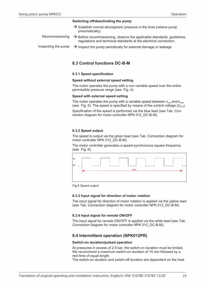
8.3.2 Speed outputThe speed is output via the green lead (see Tab. Connection diagram formotor controller NPK 012_DC-B-M).The motor controller generates a speed-synchronous square frequency(see Fig. 6).
Fig.6 Speed output
8.3.3 Input signal for direction of motor rotationThe input signal for direction of motor rotation is applied via the yellow lead(see Tab. Connection diagram for motor controller NPK 012_DC-B-M).
8.3.4 Input signal for remote ON/OFFThe input signal for remote ON/OFF is applied via the white lead (see Tab.Connection diagram for motor controller NPK 012_DC-B-M).
8.4 Intermittent operation (NPK012PR)Switch-on duration/pulsed operationAt pressures in excess of 2.5 bar, the switch-on duration must be limited.We recommend a maximum switch-on duration of 15 min followed by arest time of equal length.The switch-on duration and switch-off duration are dependent on the heat

Operation Swing piston pump NPK012
24 Translation of original operating and installation instruction, Englisch, KNF 316780-316783 12/20
generated in the pump head as well as its heat dissipation while at rest. Ifthe pump is allowed to cool further, the switch-on duration can be ex-tended or the rest phase shortened.The maximum permissible temperature in operation should not exceed150°C at the pump head and 95°C at the motor housing.See sketch for measuring point:
Measuring point formax. temperature onpump head
Measuring point formax. temperature onmotor housing
Fig.7 Temperature measuring points NPK012
Contact KNF Customer Service for further information. Contact data: seewww.knf.de.

Swing piston pump NPK012 Cleaning
Translation of original operating and installation instruction, Englisch, KNF 316780-316783 12/20 25
9 Cleaning
9.1 Flushing the pumpWhen transferring dangerous and environmentally hazardous media, KNFrecommends flushing the pump at atmospheric pressure for a few minutesprior to switch-off (if necessary for safety reasons: with an inert gas) to ex-tend the service life of the diaphragm.
à Discharge the media safely.
9.2 Flushing the pumpWhen transferring dangerous and environmentally hazardous media, KNFrecommends flushing the pump with air at atmospheric pressure for a fewminutes prior to switch-off (if necessary for safety reasons: with an inertgas) to extend the service life of the sealing lip.
à Discharge the media safely.
9.3 Cleaning the pump
CAUTION
Risk of burns from hot pump partsThe pump head or motor may still be hot after op-eration of the pump.
à Allow the pump to cool after operation.
WARNING
Health hazard due to dangerous substances in thepumpDepending on the medium being transferred,caustic burns or poisoning is possible.
àWear protective equipment if necessary, e.g.,protective gloves, goggles.
àClean the pump with suitable measures.
NOTICE
During cleaning work, ensure that no fluids enterthe interior of the housing.
à Solvents should only be used during cleaning if head materials are notcorroded (ensure resistance of the material).
à If possible, the parts should be cleaned dry with a cloth. Solventsshould not be used during cleaning because they could attack theplastic parts.
à If there is any compressed air left, blow out the parts.

Troubleshooting Swing piston pump NPK012
26 Translation of original operating and installation instruction, Englisch, KNF 316780-316783 12/20
10 Troubleshooting
DANGER
Danger to life from electric shock
àAll work on the pump may only be performedby an authorized specialist.
àDisconnect the pump power supply beforeworking on the pump.
àCheck and ensure that no voltage is present.
à Allow the pump to cool before troubleshooting.
à Check the pump (see following tables).
Pump does not transferCause Fault remedyPump is not connected to the elec-trical mains.
à Connect the pump to the electrical mains.
No voltage in the electrical mains. à Check the room fuse and switch it on if neces-sary.
Connections or lines are blocked. à Check the connections and lines.
à Remove the blockage.External valve is closed or filter isplugged.
à Check external valves and filters.
Condensate has collected in thepump head.
à Separate the source of the condensate from thepump.
à Flush the pump with air at atmospheric pressurefor a few minutes (if necessary for safety reasons:with an inert gas).
à Install the pump at the highest location in the sys-tem.
Max. voltage range of motor ex-ceeded.
à Disconnect pump from electrical mains.
à The applied voltage must not exceed the valuespecified in Chapter 7.2 Electrical connection.
Tab.11

Swing piston pump NPK012 Troubleshooting
Translation of original operating and installation instruction, Englisch, KNF 316780-316783 12/20 27
Flow rate, pressure or vacuum too lowThe pump is not achieving the flow rate specified in the technical specifications orin the data sheet.Cause Fault remedyCondensate has collected in thepump head.
à Separate the source of the condensate from thepump.
à Flush the pump with air at atmospheric pressurefor a few minutes (if necessary for safety reasons:with an inert gas).
à Install the pump at the highest location in the sys-tem.
There is overpressure on the pres-sure side and at the same timevacuum or pressure above atmo-spheric pressure on the suctionside.
à Change the pneumatic conditions.
Pneumatic lines or connectionparts have insufficient cross sec-tion or are throttled.
à Disconnect the pump from the system to deter-mine the output values.
à Eliminate throttling (e.g., valve) if necessary.
à Use lines or connection parts with a larger cross-section if necessary.
Leaks occur at connections, linesor pump head.
à Eliminate the leaks.
Connections or lines are com-pletely or partially plugged.
à Check the connections and lines.
à Remove any parts and particles that are causingplugging.
Head parts are soiled. à Clean the head components.Damaged sealing lip à Stop the pump immediately.
Tab.12
Pump exhibiting changed running noises and vibrations.Cause Fault remedyPump bearing worn or defective. à Determine the cause.
à Contact KNF Customer Service.Motor worn or defective. à See operating instructions for the motor.
Tab.13
Fault cannot be rectifiedIf you are unable to identify any of the specified causes, send the pump toKNF Customer Service (contact data: see www.knf.com).1. Flush the pump with air at atmospheric pressure for a few minutes (if
necessary for safety reasons: with inert gas) to free the pump head ofdangerous or aggressive gases (see Chapter 9.1 Flushing the pump).
2. Clean the pump (see Chapter 9.3 Cleaning the pump).3. Send the pump together with completed Health and Safety Clearance
and Decontamination Form to KNF, specifying the pumped medium.

Accessories Swing piston pump NPK012
28 Translation of original operating and installation instruction, Englisch, KNF 316780-316783 12/20
11 AccessoriesAccessories Order numberInlet filter 319074Silencer / Muffler 058987Housing cover set 325019Base plate set 325020Tab.14
Fig.8 Accessory cover set and base plate set

Swing piston pump NPK012 Returns
Translation of original operating and installation instruction, Englisch, KNF 316780-316783 12/20 29
12 ReturnsPreparing for return1. Flush the pump with air for a few minutes (if necessary for safety rea-
sons: with inert gas) to free the pump head of dangerous or aggressive gases (see Chapter Flushing the pump).
2. Remove the pump.3. Clean the pump (see Chapter Cleaning the pump).4. Send the pump together with completed Health and Safety Clearance
and Decontamination Form to KNF, stating the nature of the trans-ferred medium.
5. Package the device securely to prevent further damage to the product. If necessary, request an original packaging at a charge.
Please contact your KNF sales partner if the pump cannot beflushed due to damages.
ReturnsKNF shall undertake to repair the pump only under the condition that thecustomer presents a certificate regarding the medium that is pumped andthe cleaning of the pump. Prior authorization from KNF is required for allproduct returns. To obtain your return authorization, please follow the in-structions at knf.com/repairs.Contact your KNF sales partner directly if you require additional support foryour return service.


KNF worldwideYou can find our local KNF partners at: www.knf.com