vws pump manual (varat pump & - baixardoc
TRANSCRIPT
Page 1 of 20
MANUAL FOR VWS PUMP
Instructions on Installations,
Operation and Maintenance of Vertical
Submersible Pumping System
Manufactured by :
Varat Pump & Machinery Pvt. Ltd.20, NETAJI SUBHAS ROAD
KOLKATA – 700 001
WEST BENGAL
INDIA
Ph. No.: 033-2230 1903, 2243 4500
FAX No.: 033-2230 1535/6274
E-Mail : [email protected]
Page 2 of 20
MANUAL VWS FOR SEWAGE PUMP
1.0 GENERAL
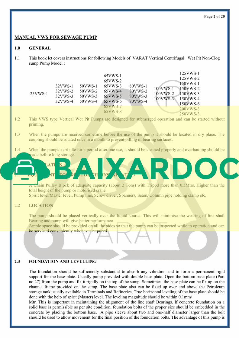
1.1 This book let covers instructions for following Models of VARAT Vertical Centrifugal Wet Pit Non-Clog
sump Pump Model :
25VWS-1
32VWS-1
32VWS-2
32VWS-3
32VWS-4
50VWS-1
50VWS-2
50VWS-3
50VWS-4
65VWS-1
65VWS-2
65VWS-3
65VWS-4
65VWS-5
65VWS-6
65VWS-7
65VWS-8
80VWS-1
80VWS-2
80VWS-3
80VWS-4
100VWS-1
100VWS-2
100VWS-3
125VWS-1
125VWS-2
150VWS-1
150VWS-2
150VWS-3
150VWS-4
150VWS-6
200VWS-3
250VWS-3
1.2 This VWS type Vertical Wet Pit Pumps are designed for submerged operation and can be started without
priming.
1.3 When the pumps are received sometime before the use of the pump it should be located in dry place. The
coupling should be rotated once in a month to prevent pilling of bearing surfaces.
1.4 When the pumps kept idle for a period after one use, it should be cleaned properly and overhauling should be
made before long storage.
2.0 INSTALLATION
2.1 EQUIPMENT REQUIRED FOR THE INSTALLATION
A Chain Pulley Block of adequate capacity (about 2 Tons) with Tripod more than 0.5Mtrs. Higher than the
total height of the pump or motorised crane.
Spirit level/Master level, Pump line, Screw driver, Spanners, Seam, Column pipe holding clamp etc.
2.2 LOCATION
The pump should be placed vertically over the liquid source. This will minimise the wearing of line shaft
Bearing and pump will give better performance.
Ample space should be provided on all the sides so that the pump can be inspected while in operation and can
be serviced conveniently whenever required
2.3 FOUNDATION AND LEVELLING
The foundation should be sufficiently substantial to absorb any vibration and to form a permanent rigid
support for the base plate. Usually pump provided with double base plate. Open the bottom base plate (Part
no.27) from the pump and fix it rigidly on the top of the sump. Sometimes, the base plate can be fix up on the
channel frame provided on the sump. The base plate also can be fixed up over and above the Petroleum
storage tank usually available in Terminals and Refineries. True horizontal leveling of the base plate should be
done with the help of spirit (Master) level. The leveling magnitude should be within 0.1mm/
Mtr. This is important in maintaining the alignment of the line shaft Bearings. If concrete foundation on a
solid base is permissible as per site condition, foundation bolts of the proper size should be embedded in the
concrete by placing the bottom base. A pipe sleeve about two and one-half diameter larger than the bolt
should be used to allow movement for the final position of the foundation bolts. The advantage of this pump is
Page 3 of 20
that of double base plate. A gap of about 25 to 50 mm should be allowed between the base plate and
foundation of grouting. Supporting will be such that it will not be distorted or sprung by the uneven
distribution of the weight. Adjust the wedges until the Four Corners and machined face of the base are in
level. Once the bottom base is fixed, it is not required to remove during maintenance because the top base will
be fixed on this bottom base having both the face machined and total assembly will pass through the opening
of the bottom plate. So, once master leveling has been made on the bottom base, it is not required to disturb
the same and no further master leveling is required during reinstallation after overhauling.
2.4 GROUTING
When the leveling is correct, the foundation bolts should be tightened evenly but not too firmly. Working soft
concrete under the edges can then grout the unit. Foundation bolts should not be fully tightened until the grout
is hardened, usually 48 hours required after pouring.
Page 4 of 20
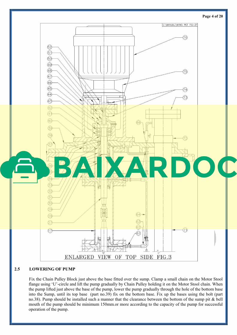
2.5 LOWERING OF PUMP
Fix the Chain Pulley Block just above the base fitted over the sump. Clamp a small chain on the Motor Stool
flange using ‘U’-circle and lift the pump gradually by Chain Pulley holding it on the Motor Stool chain. When
the pump lifted just above the base of the pump, lower the pump gradually through the hole of the bottom base
into the Sump, until its top base (part no.39) fix on the bottom base. Fix up the bases using the bolt (part
no.38). Pump should be installed such a manner that the clearance between the bottom of the sump pit & bell
mouth of the pump should be minimum 150mm.or more according to the capacity of the pump for successful
operation of the pump.

Page 5 of 20
Verticality of the pump should be checked after installation, with the help of pump line. Provide lubrication
pot on the base plate.
Pump can be lowered in the sump part by part using a holding clamp above the base and following the re-
assembling procedure.
2.6 ALIGNMENT
Pump supplied by the manufacturers provided with a Motor Stool, which has been designed, for a particular
suitable International frame of the motor. After lowering of the pump fix up the Flange mounted Motor on the
top flange which will fit with the fitting of the Motor Stool. If the pump and motor are provided with a
coupling this will align automatically and no further alignment is required. Just put the Pin Bush of the
coupling after free running of Motor (without load) for at least One hour. Check up the direction of the
rotation of the motor during free running. Check up the alignment whether correct or not. If alignments found
wrong then check up the fitting of Motor Stool flange with the motor flange. Also check the coupling halves
of the pump and motor if any misalignment found.
2.7 FLEXIBLE COUPLING
A flexible coupling will not compensate for misalignment of the pump and driver shafts. The purpose of the
flexible coupling is to compensate for temperature changes and to permit the movement of the shafts without
interference with each other while transmitting power from the driver to the pump.
2.8 MISALIGNMENT
There are two types of misalignment between the Pump shaft and the driver shaft:
(a) Angular misalignment: Shafts with axis concentric but not parallel.
(b) Parallel misalignment: Shafts with axis Parallel but not concentric.
The faces of the coupling should be spaced for enough apart so that they cannot strike each other when the
drive shaft of the rotor is moved over the pump half. Due allowance should be made for wear of the thrust
Bearings. A minimum gap of 3 to 4 mm should be maintained. The necessary tools for approximately
checking the alignment of the flexible coupling are a straight edge and a taper gauge or a set of feeler gauge.
For pin bush coupling disconnect coupling halves before proceeding with alignment. A check for angular
alignment is made by inserting the taper gauge or feelers at four points between the coupling faces and
comparing the distance between the faces at four points spaced at 90 degree intervals around the coupling, the
unit will be in angular alignment when the measurement show that the coupling faces are the same distance
apart at all point (FIG 1). A check for parallel alignment is made by placing a straight edge across both
coupling ring at the top bottom and at both sides. The unit will be in parallel alignment when the straight edge
rests evenly on the coupling ring at all positions. Care must be taken to have the straight edge parallel to the
axis of the shaft (FIG-2). It should not be necessary to adjust the shims, if used, under the pump.
Page 6 of 20
2.9 PIPING
Delivery pipe and accessories after special pipe (Part no.47) should be independently supported near the pump
so that when the flange bolts are tightened no strain will be transmitted to the special pipe which effect the
strain on pump casing. It is usually advisable
to increase the size of delivery pipes but not to decrease at the pump nozzles in order to decrease the loss of
head from friction and for the same reason piping should be arranged with as minimum bends as possible, as
these should be made with a long radius wherever possible. The pipelines should be free from scales, welding
residuals etc., and have to be mounted in such way that they can be connected to delivery flanges without any
stress on the pump. Adequate supports should be given to pipe lines so that the weight of the pipelines does
not fall on the pump. The use of minimum number of the bends and other fittings will minimise the friction
losses.
2.10 DELIVERY VALVES AND FITTINGS
A check (non-return) valve and a gate or sluice valve (regulating valve) should be installed in the discharge
line. The check valve placed between the pump and the gate valve is to protect the pump from excessive
pressure and to prevent water running back through the pump in case of failure of the driving machine i.e-
excessive back pressure.
Discharge piping should be provided with a sluice valve to control the discharge, if required. The valve had to
be used in starting and when shutting down the pumps. If enlarger are used on the discharge side to increase
the size of discharge piping they should be placed between the check valve and pump. Arrangement for three
ways connection of pressure gauge with air-cock should be after delivery flange but before delivery sluice
valve is required.
2.11 MECHANICAL SEAL
Since mechanical seals are made in a wide variety of designs, the instruction for the specific seal must be
carefully studied and followed exactly. A Mechanical Seal is a precision device and must be treated
accordingly. It is provided at the Lower Bearing Housing to prevent the entering of liquid inside column pipe
of the pump.
2.12 LUBRICATION
Pump is usually provided with a special gravity feed oil lubrication pot or screwed type grease lubrication pot.
Fix up the pot above the base plate and fill it with oil or grease, if the pump is not self or water lubricated. For
self/water lubrication pump, a regulating valve already provided and connected with the base plate. Open the
valve before starting of the pump.
2.13 BALL BEARING
Correct maintenance of ball bearings is essential. The bearing manufacturers give the following as guide to
relubrication periods under normal conditions. Three monthly when on continuous duty.
Six monthly when on eight-hour per day duty.
The bearings and housings should be completely cleaned and recharged with fresh grease after 2500 hours or
the nearest pump overhaul time.
2.14 PRIMING
No priming is required for this pump as the pump bowl assembly submerged inside the liquid.
3.0 PREPARATION OF PUMP STARTING:
After the pump and the drive are mounted, the plant should be prepared for starting. The following rules
should be observed before starting the pump:
Page 7 of 20
3.1 The pins or pad should be inserted into the coupling not before making sure of the correct rotation of drive. In
case of the drive rotating in the wrong direction, the connection of two cable conductors out of the three
supplying the current to the motor should be interchange in case of DOL starting.
3.2 Check presence of grease / oil in bearings and correct location of lubrication line for line shaft bearings,
ensure flashing, quenching and lubrication in case of mechanical seal as well as if required as per design.
3.3 Check the free rotation of pump rotor, turning it by hand to verify any major obstruction or friction with
wearing parts.
3.4 Check the proper order of delivery and pressure pipelines, tightening of flanges, fittings of outlet valve and
presence of drain plug (if any).
3.5 Close the Sluice valve at the delivery side.
3.6 Making reasonably sure of the proper order of the whole plant and its readiness for operation, you can startthe pump.
4.0 STARTING AND STOPPING OF THE PUMP:
4.1 Open the stop-cock of pressure gauge .The pump should be loaded gradually, when the drive is engaged. When
the prime mover attain full speed, the regulating sluice valve should be smoothly opened. This will avoid
overloading of the drive.
On the other hand it should be kept in mind that a lengthy operation with completely close
sliding valve is likewise to be avoided. Since this causes unnecessary heating of the liquid
in the pump.
4.2 By controlling the sliding valve the required flow and head may be obtained. After setting
of pressure gauge at required point, check ampere consumption, if found exceed required
value, pump should be stopped. During running also check about any abnormal sound from
the pump or smooth running of the pump set.
4.3 For stopping of the pump first close the delivery valve then stop the pump.
5.0 TECHNICAL INFORMATIONS:
5.1 DIRECTION OF ROTATION
Standard rotation of the pump is clockwise, when viewed from the driving end.
5.2 BEARINGS
The pump is supplied with anti-friction ball bearings and angular contact bearing at
driving end and usually of SKF/RHP/NBC make. Line shaft bush bearings are made of
bronze or cartilage rubber suitable for self-lubrication or oil-lubrication.
5.3 LUBRICATION:
Ball bearings are normally greased lubricated. Refilling period is after 1000 hours of running. Bearing
temperature is permissible to rise 40 degree Centigrade above ambient temperature. Grades of recommended
grease are INDIAN OIL- SERVOGEM-3 or CALTEX-STARFAX-3, H.P.C.L. NATRA-3 or equivalent. In
case of oil lubrication bearing for line shaft bushes, oil should be maintained in the oil pot. Servo 30/40 may
be used for this purpose. For self-lubrication pumping liquid should be free from any particles.
Page 8 of 20
5.4 GASKET
Compressed asbestos packing gasket for joining of volute casing is used. However, packing gasket suitable to
handle corrosive liquid and high temperature fluid is supplied against specific requirements.
5.5 COUPLING
Normally pin-bush flexible type or star type spider coupling without spacer (for small size motor) is used.
Other type of coupling may be supplied against specific requirements. Pin-bush type coupling is more suitable
for this pump because after placement of the motor above the pump, the free rotation of the pump can be
possible just not to provide the pin-bush of the coupling and pump may be coupled with the motor just
providing the pin bushes after checking of the rotation.
5.6 GUIDE RING / WEARING RING
Replaceable ring for protection of suction cover and LBH plate provided in VWS type pumps. If not specified,
it is usually of non-sparking (Bronze) material.
5.7 SHAFT SLEEVES
Replaceable sleeve for protection of the shaft at lower bearing housing and sleeve for Mechanical seal are
provided.
5.8 MECHANICAL SEAL
The pump is not usually supplied with a mechanical seal. If provided, stationary face (mating ring) is fitted in
the seal retainer by press fit providing ‘O’ ring at the L.B.H. plate. Rotating part is fitted on the pump sleeve.
6.0 SPARE PARTS
One set Anti-friction bearing, one bottom shaft, one impeller, one L.B.H plate, one set Wearing Ring, one set
Shaft Sleeve, one set Bush Bearings, ‘O’ Rings, Impeller Lock Bolt, Gasket and one set of mechanical seal kit
against each pump must always be kept with the actual users of the pump to ensure uninterrupted service from
the pump.
Page 9 of 20
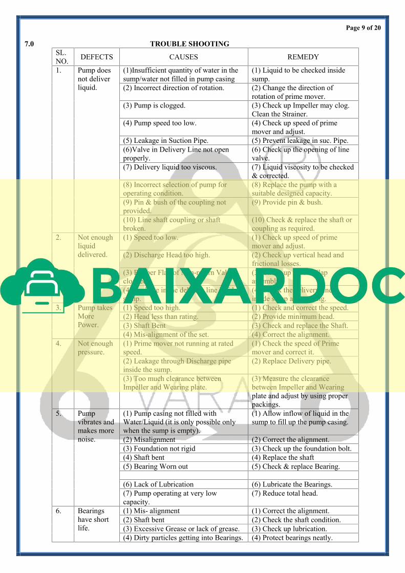
7.0 TROUBLE SHOOTING
SL.
NO.DEFECTS CAUSES REMEDY
1. Pump does
not deliver
liquid.
(1)Insufficient quantity of water in the
sump/water not filled in pump casing
(1) Liquid to be checked inside
sump.
(2) Incorrect direction of rotation. (2) Change the direction of
rotation of prime mover.
(3) Pump is clogged. (3) Check up Impeller may clog.
Clean the Strainer.
(4) Pump speed too low. (4) Check up speed of prime
mover and adjust.
(5) Leakage in Suction Pipe. (5) Prevent leakage in suc. Pipe.
(6)Valve in Delivery Line not open
properly.
(6) Check up the opening of line
valve.
(7) Delivery liquid too viscous. (7) Liquid viscosity to be checked
& corrected.
(8) Incorrect selection of pump for
operating condition.
(8) Replace the pump with a
suitable designed capacity.
(9) Pin & bush of the coupling not
provided.
(9) Provide pin & bush.
(10) Line shaft coupling or shaft
broken.
(10) Check & replace the shaft or
coupling as required.
2. Not enough
liquid
delivered.
(1) Speed too low. (1) Check up speed of prime
mover and adjust.
(2) Discharge Head too high. (2) Check up vertical head and
frictional losses.
(3) Rubber Flap of Non-return Valve
clogged.
(3) Check up rubber Flap
assembly.
(4) Leakage in the delivery line inside
sump.
(4) Check the delivery line
inside sump after casing.
3. Pump takes
More
Power.
(1) Speed too high. (1) Check and correct the speed.
(2) Head less than rating. (2) Provide minimum head.
(3) Shaft Bent (3) Check and replace the Shaft.
(4) Mis-alignment of the set. (4) Correct the alignment.
4. Not enough
pressure.
(1) Prime mover not running at rated
speed.
(1) Check the speed of Prime
mover and correct it.
(2) Leakage through Discharge pipe
inside the sump.
(2) Replace Delivery pipe.
(3) Too much clearance between
Impeller and Wearing plate.
(3) Measure the clearance
between Impeller and Wearing
plate and adjust by using proper
packings.
5. Pump
vibrates and
makes more
noise.
(1) Pump casing not filled with
Water/Liquid (it is only possible only
when the sump is empty).
(1) Allow inflow of liquid in the
sump to fill up the pump casing.
(2) Misalignment (2) Correct the alignment.
(3) Foundation not rigid (3) Check up the foundation bolt.
(4) Shaft bent (4) Replace the shaft
(5) Bearing Worn out (5) Check & replace Bearing.
(6) Lack of Lubrication (6) Lubricate the Bearings.
(7) Pump operating at very low
capacity.
(7) Reduce total head.
6. Bearings
have short
life.
(1) Mis- alignment (1) Correct the alignment.
(2) Shaft bent (2) Check the shaft condition.
(3) Excessive Grease or lack of grease. (3) Check up lubrication.
(4) Dirty particles getting into Bearings. (4) Protect bearings neatly.
Page 10 of 20
8.0 MAINTENANCE
Preventative maintenance schedule is the periodical checks and precautions by which possibilities of failures
and breakdowns are made very remote.
8.1 Daily Checks
1.1 Pressure gauge reading
1.2 Bearing temperature
1.3 Noise and vibration
1.4 Voltage and current
1.5 Constant flow of cooling & lubrication liquid.
8.2 Periodical Maintenance
1.1 Replenish the grease
1.2 Change the stuffing box packing
1.3 Check the alignment of the pump set
1.4 Calibrate the measuring instruments
1.5 Check the sealing and cooling connections for leakage etc.
9.0 OVERHAULING
Normally the pump will be due for overhauling after about 3000 working hours. Pump dismantling and
assembling should be done by skilled personal. Special attention should be given to continuous running
pumps & advice to keep stand by pump for emergency services.
10.0 DISMANTLING & REASSEMBLING PROCEDURE
Pump can be dismantled from the driving end side or non-driving end side. When the pump
is on the horizontal ground (we refer this as horizontal mode) then it is required to start the
dismantling from non-driving end. But when pump has to be removed part by part from the sump due to lack
of vertical space above the sump than the pump has to be dismantled starting from driving end of the pump.
10.1 INFORMATION ABOUT DESIGN
All VWS type Pumps for sewage application having more than one column pipe assembly are divided into
two groups from the design point of view.
Design No.1. Pump with screwed type line shaft coupling and with oil seal system having
external oil lubrication.
Design No.2. Pump with screwed type line shaft coupling and without oil seal for self-liquid lubrication.
Fig. No. 3 explained the design no.1.
When part no.54, 55, 56, 58, 59 & 60 are not provided in design no.1 then it is identify as design no.2.
In case of pump having single column pipe assembly no intermediate holder or shaft coupling are used and
pump having only single combine shaft (fig. No.4).