high pressure piston pumps
TRANSCRIPT
1
2
HIGH PRESSUREPISTON PUMPS
You have decided to show your preference for the "BERTOLINI" brand and have bought a productwhich has been manufactured with the benefit of the most modern technology and the finest mate-rials, designed through research to ensure its improved quality, duration and functionality.
We thank you for the trust shown in our products.
Please read this booklet with care and always keep it within easy reach. You will find it useful inresolving any problem you may have with regard to the characteristics and functionality of theproduct.
Thank you for having chosen "BERTOLINI”
We at Idromeccanica Bertolini recommend that you read this Use and Mainte-nance Manual carefully before installing and using the pump. You should keep itwithin easy reach for any further reference. The Manual should be considered as anintegral part of the pump itself.
Any person using the pump is expected to observe the relevant legislative provisions currently inforce in the country where the pump is to be used. They are also required to follow the instructionsset out in this Manual with care.
A- INTENDED USE
CAUTION
· The pump is only intended for pumping:- high-pressure water in washing machines (water cleaners);- water not for food use.
· The pump is not intended for distributing:- non – filtered water or water with dirt;- detergents, paints and chemical substances both in their pure state and in water so-
lution;- sea water or high salt concentration water;- fuels and lubricants of any kind and type;- flammable fluids or liquefied gases;- food liquids;- water with temperature higher than 60°C or lower than 5°C;
· the pump must be never used to wash : persons, animals, electrical devices under voltage,delicate objects, the pump itself or the machine it is part of.
· The accessories (standard and optional) and the detergents used with the pump must be ofthe type authorised by the Producer .
· The pump is not suitable for the use in rooms that show particular conditions such as, forinstance, corrosive or explosive atmospheres.
· For the use on vehicles, boats or aircraft, apply to the technical service of the Producer, be-cause some added prescriptions can be necessary.Any other use is improper.The Producer cannot be hold liable for possible damage resulting from unintendedor wrong uses.
3
B. OPERATION
PRELIMINARY ACTIVITIES
CAUTION
· The pump cannot be commissioned if the machine that incorporates it does not con-form to the safety requirements established by European Directives. This conformityis guaranteed by the presence of the CE marking and by the Declaration of Conformi-ty of the Producer of the machine incorporating the pump.
· Before starting up the machine, carefully read the indications of this manual and the instruc-tions of the machine incorporating the pump. In particular, make sure that you have wellunderstood the operation of the pump and of the machine incorporating the pump as far asthe fluid sensing operations are concerned.
· Carry out the preliminary checks recommended by the producer of the machine incorporat-ing the pump.
· Check that all delivery pipes are closed or connected to users in closed position (for in-stance water gun)
· Make sure that the pump moving parts are suitable protected and that they cannot be ac-cessed by unauthorised personnel.
· Do not use the pump in case:- the pump has undergone strong hurts;- there are oil leaks;- there are visible water leaks;
In these cases have the pump be checked by a Skilled Engineer.· Have a Specialized Engineer make the scheduled checks as per the extraordinary
maintenance.
WARNING· In case of use at very low temperature, make sure that there is no ice inside the pump.· Carry out the scheduled checks of the routine maintenance with special reference to the
ones relating to oil.
a) Replace the oil plug without vent pos.2 by the oil plug with vent. This operation could havealready been carried out by the Producer of the machine incorporating the pump.
b) With pump at a standstill, check that the oil level corresponds to the middle of the oil levellight. The oil level can be also checked by unscrewing the plug with vent: the correct levelmust be included between the two notches on the rod. Remember that the oil level must bealways checked with pump at a standstill and completely cooled down.For possible filling, refer to the types of lubricants reported in paragraph 12 “Lubrication”.
c) By referring to the use and maintenance manual of the machine incorporating the pump,check the cleaning of the suction filter.
4
This Use and Maintenance Booklet is made up of the following chapters:
1. General Safety Rules.2. Product Description3. Technical Features Identification of components Selection of pump and equipment design4. Installation Pump- motor coupling Inlet circuit5. High pressure circuit6. Selection of the nozzle7. Unloader valves- Pressure relief valves
7.a. Technical features- DescriptionUnloader valves - Starting procedure7.b. Pressure adjusting7.c. Troubles and cures during the starting procedure
8. Pump- Starting procedure9. Operation
9.1 Operation with detergent10. Shut down procedure, cleaning and standstill11. Starting procedure after long time of no operation12. Lubrication13. Routine maintenance14. Troubleshooting pump/unloader by-pass valve15. Limited Warranty
ROUTINE SERVICE AND REPAIRA. PumpA.1. Check valvesA.2. Packings/ SealsA.3. Ceramic plungersB. Unloader valve
Notes:a) This Manual is based on, and complies with, technical knowledge applicable as at the date
of sale of the product and shall not be considered inadequate for the sole reason that it hasbeen up-dated on the basis of new knowledge/experience.IDROMECCANICA BERTOLINI S.p.A. has the right to up-date its products and relatedmanuals without being thereby obliged to up-date previous products and manuals, save incases deriving exclusively from safety considerations.
b) You may consult our Customer Service in relation to any query or need arising when using orservicing the product and to obtain assistance in choosing accessories to use with it.
c) No part of this Manual may be reproduced without the written permission ofIDROMECCANICA BERTOLINI S.p.A.
5
1- GENERAL SAFETY RULES
The high energy on the pressure jet is a source of serious dangers.
The pump must be used only by skilled personnel.
It is strongly recommended to fit mechanically pre-fastened high pressure hoses. Theymust be homologated for the Max. admissible pressure in the system, and they must carryover the stamping of the overpressure and the max. admissible temperature, besides thename of the producer and date of production.
Before starting check always your machine. Particularly check the integrity of plumbing,high pressure fittings, the gun trigger that should work in a soft way, without releases andimmediately return to its position, when off.
Do not install defective high pressure hose and do not try to repair it, rather replace it by anoriginal spare part.
Keep children and animals away from the pump.
Make sure that your system is installed on a strong and safe base.
Always wear eye protection and protective clothing when operating.
Hold always the gun with both hands. Do not open the pressure jet without holding firmlythe trigger gun.
Do not turn the jet against persons, animals and fragile objects.
Do not turn the jet against cables or electric equipment, sockets or nearby.
Do not place yourself in front of the pressure jet.
To clean the delicate surfaces use exclusively fan-shaped jets and keep nozzle 75 cmaway.
Do not operate gasoline engine in an enclosed area. Be sure that the area is well ventilat-ed.
THE EXHALATION OF THE EXHAUST GAS COULD BE MORTAL!
Provide adequate protection in guarding around the moving parts.
Do not use the equipment to clean surfaces that contain asbestos.
Follow strictly the current regulations of draining of the substances taken down from thesurfaces where the pressure jet is used.
Carry out the preliminary checks recommended by the producer of the machine that incor-porates the pump.
High pressure jet is dangerous: do not turn the jet against yourself or others.
Pump must not be used by children or not trained personnel.
Idromeccanica Bertolini S.p.A. declines any civil or criminal liability for damage or accidents to personsor property as may arise from the failure to observe even only one of the above safety rules
6
2- PRODUCT DESCRIPTION
Bertolini high pressure piston pumps are designed to pump clean water, and can be used with atemperature up to 60°C.Do not pump acids or abrasive fluids; consult factory for additional information on questionable flu-ids.Pump operation must be within the specifications indicated on the label (fig. 1); do not remove la-bel, otherwise the warranty will be void.
3- TECHNICAL FEATURES
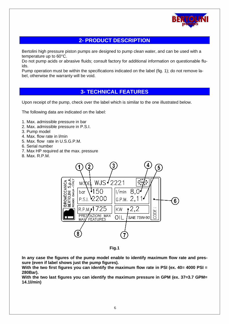
Upon receipt of the pump, check over the label which is similar to the one illustrated below.
The following data are indicated on the label:
1. Max. admissible pressure in bar2. Max. admissible pressure in P.S.I.3. Pump model4. Max. flow rate in l/min5. Max. flow rate in U.S.G.P.M.6. Serial number7. Max HP required at the max. pressure8. Max. R.P.M.
Fig.1
In any case the figures of the pump model enable to identify maximum flow rate and pres-sure (even if label shows just the pump figures).With the two first figures you can identify the maximum flow rate in PSI (ex. 40= 4000 PSI =280Bar).With the two last figures you can identify the maximum pressure in GPM (ex. 37=3.7 GPM=14.1l/min)
7
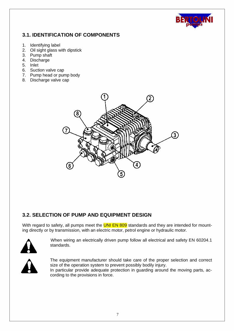
3.1. IDENTIFICATION OF COMPONENTS
1. Identifying label2. Oil sight glass with dipstick3. Pump shaft4. Discharge5. Inlet6. Suction valve cap7. Pump head or pump body8. Discharge valve cap
Fig. 2
3.2. SELECTION OF PUMP AND EQUIPMENT DESIGN
With regard to safety, all pumps meet the UNI EN 809 standards and they are intended for mount-ing directly or by transmission, with an electric motor, petrol engine or hydraulic motor.
When wiring an electrically driven pump follow all electrical and safety EN 60204.1standards.
The equipment manufacturer should take care of the proper selection and correctsize of the operation system to prevent possibly bodily injury.In particular provide adequate protection in guarding around the moving parts, ac-cording to the provisions in force.
8
4- INSTALLATION
Correct installation is the determining factor for good functioning and long life of thepump.90% of failures and of the misfunctions are consequence of:
· Wrong coupling between pump and motor/engine.· Wrong inlet circuit.· Poor quality or not correct adjusting of the unloader valve or pressure relief valve.
Idromeccanica Bertolini S.p.A. declines any liability as may arise from the failure to observeeven only one of the following instructions:
4.1. PUMP-MOTOR COUPLING
Ø In order to obtain correct lubrication of all moving parts the pump must work with the axis ofthe pistons in horizontal position.
Ø The pump-motor/engine assembly must be properly installed on a strong base plate.
Ø When wiring an electrically driven pump follow all electrical and safety EN 60204.1 stand-ards to prevent accidents.
Ø All wiring must be done by qualified electricians.
· In case of direct coupling to motor/engine be sure that:
- the motor/engine shaft is perfectly aligned and centered as to the pump shaft- the key is of correct length- the pump flange leans against the motor flange before tightening bolts
· In case of gearbox drive follow the same above recommendations as to the couplingbetween flanges and between motor/engine shaft- primary shaft and driven shaft-pump shaft
· In case of pulleys drive check:
- there is no slack between shafts and pulleys- that pulleys are parallel and aligned- that belts are correctly stretched. An excessive belts tension will cause prema-
ture wear of the bearings.
9
4.2. INLET CIRCUIT
Inlet can be either in pressure (for all models of pumps) or in suction (only for a few models).
Ø In any case we recommend to fit an inlet strainer rated at least 2 times the rated flow of thepump.
Ø In case of inlet in pressure from water system be sure that the flow is suited to that one ofthe pump. The inlet pressure cannot exceed 5 bar. (72 P.S.I.)
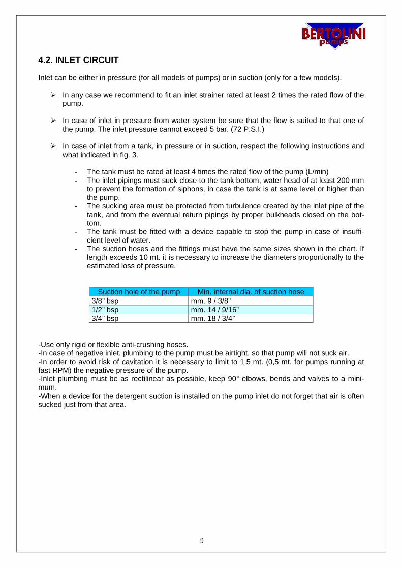
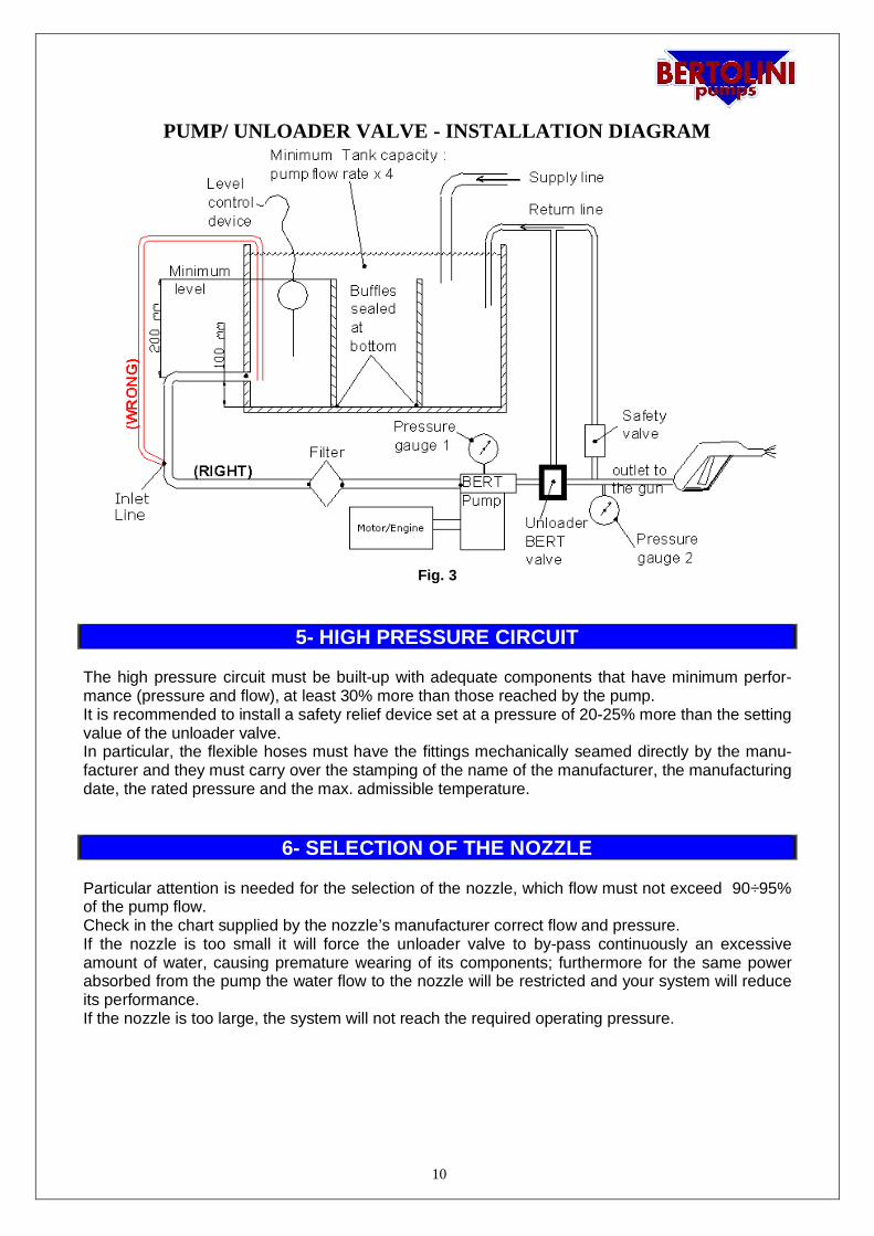
Ø In case of inlet from a tank, in pressure or in suction, respect the following instructions andwhat indicated in fig. 3.
- The tank must be rated at least 4 times the rated flow of the pump (L/min)- The inlet pipings must suck close to the tank bottom, water head of at least 200 mm
to prevent the formation of siphons, in case the tank is at same level or higher thanthe pump.
- The sucking area must be protected from turbulence created by the inlet pipe of thetank, and from the eventual return pipings by proper bulkheads closed on the bot-tom.
- The tank must be fitted with a device capable to stop the pump in case of insuffi-cient level of water.
- The suction hoses and the fittings must have the same sizes shown in the chart. Iflength exceeds 10 mt. it is necessary to increase the diameters proportionally to theestimated loss of pressure.
Suction hole of the pump Min. internal dia. of suction hose3/8” bsp mm. 9 / 3/8”1/2” bsp mm. 14 / 9/16”3/4” bsp mm. 18 / 3/4”
-Use only rigid or flexible anti-crushing hoses.-In case of negative inlet, plumbing to the pump must be airtight, so that pump will not suck air.-In order to avoid risk of cavitation it is necessary to limit to 1.5 mt. (0,5 mt. for pumps running atfast RPM) the negative pressure of the pump.-Inlet plumbing must be as rectilinear as possible, keep 90° elbows, bends and valves to a mini-mum.-When a device for the detergent suction is installed on the pump inlet do not forget that air is oftensucked just from that area.
10
PUMP/ UNLOADER VALVE - INSTALLATION DIAGRAM
Fig. 3
5- HIGH PRESSURE CIRCUIT
The high pressure circuit must be built-up with adequate components that have minimum perfor-mance (pressure and flow), at least 30% more than those reached by the pump.It is recommended to install a safety relief device set at a pressure of 20-25% more than the settingvalue of the unloader valve.In particular, the flexible hoses must have the fittings mechanically seamed directly by the manu-facturer and they must carry over the stamping of the name of the manufacturer, the manufacturingdate, the rated pressure and the max. admissible temperature.
6- SELECTION OF THE NOZZLE
Particular attention is needed for the selection of the nozzle, which flow must not exceed 90÷95%of the pump flow.Check in the chart supplied by the nozzle’s manufacturer correct flow and pressure.If the nozzle is too small it will force the unloader valve to by-pass continuously an excessiveamount of water, causing premature wearing of its components; furthermore for the same powerabsorbed from the pump the water flow to the nozzle will be restricted and your system will reduceits performance.If the nozzle is too large, the system will not reach the required operating pressure.
11
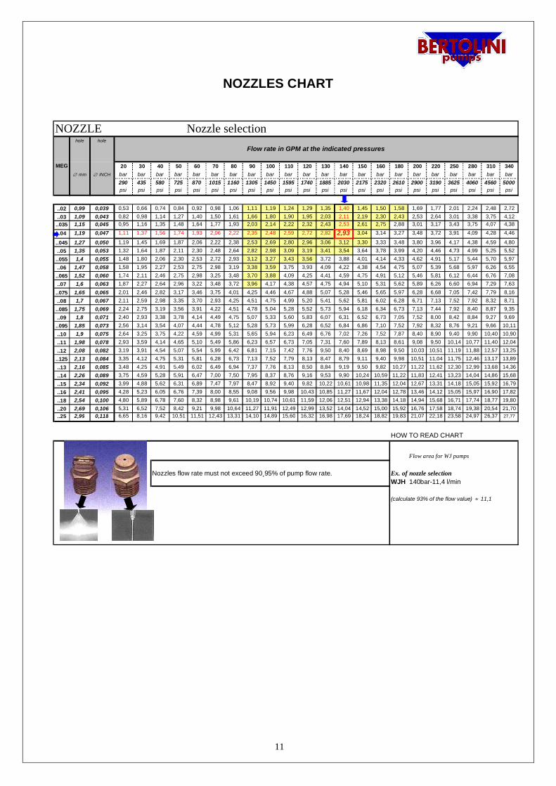
NOZZLES CHART
hole hole
20 30 40 50 60 70 80 90 100 110 120 130 140 150 160 180 200 220 250 280 310 340Æ mm Æ INCH bar bar bar bar bar bar bar bar bar bar bar bar bar bar bar bar bar bar bar bar bar bar
290 435 580 725 870 1015 1160 1305 1450 1595 1740 1885 2030 2175 2320 2610 2900 3190 3625 4060 4560 5000psi psi psi psi psi psi psi psi psi psi psi psi psi psi psi psi psi psi psi psi psi psi
..02 0,99 0,039 0,53 0,66 0,74 0,84 0,92 0,98 1,06 1,11 1,19 1,24 1,29 1,35 1,40 1,45 1,50 1,58 1,69 1,77 2,01 2,24 2,48 2,72
..03 1,09 0,043 0,82 0,98 1,14 1,27 1,40 1,50 1,61 1,66 1,80 1,90 1,95 2,03 2,11 2,19 2,30 2,43 2,53 2,64 3,01 3,38 3,75 4,12..035 1,15 0,045 0,95 1,16 1,35 1,48 1,64 1,77 1,93 2,03 2,14 2,22 2,32 2,43 2,53 2,61 2,75 2,88 3,01 3,17 3,43 3,75 4,07 4,38
..04 1,19 0,047 1,11 1,37 1,56 1,74 1,93 2,06 2,22 2,35 2,48 2,59 2,72 2,82 2,93 3,04 3,14 3,27 3,48 3,72 3,91 4,09 4,28 4,46
..045 1,27 0,050 1,19 1,45 1,69 1,87 2,06 2,22 2,38 2,53 2,69 2,80 2,96 3,06 3,12 3,30 3,33 3,48 3,80 3,96 4,17 4,38 4,59 4,80..05 1,35 0,053 1,32 1,64 1,87 2,11 2,30 2,48 2,64 2,82 2,98 3,09 3,19 3,41 3,54 3,64 3,78 3,99 4,20 4,46 4,73 4,99 5,25 5,52
..055 1,4 0,055 1,48 1,80 2,06 2,30 2,53 2,72 2,93 3,12 3,27 3,43 3,56 3,72 3,88 4,01 4,14 4,33 4,62 4,91 5,17 5,44 5,70 5,97..06 1,47 0,058 1,58 1,95 2,27 2,53 2,75 2,98 3,19 3,38 3,59 3,75 3,93 4,09 4,22 4,38 4,54 4,75 5,07 5,39 5,68 5,97 6,26 6,55
..065 1,52 0,060 1,74 2,11 2,46 2,75 2,98 3,25 3,48 3,70 3,88 4,09 4,25 4,41 4,59 4,75 4,91 5,12 5,46 5,81 6,12 6,44 6,76 7,08..07 1,6 0,063 1,87 2,27 2,64 2,96 3,22 3,48 3,72 3,96 4,17 4,38 4,57 4,75 4,94 5,10 5,31 5,62 5,89 6,26 6,60 6,94 7,29 7,63
..075 1,65 0,065 2,01 2,46 2,82 3,17 3,46 3,75 4,01 4,25 4,46 4,67 4,88 5,07 5,28 5,46 5,65 5,97 6,28 6,68 7,05 7,42 7,79 8,16..08 1,7 0,067 2,11 2,59 2,98 3,35 3,70 2,93 4,25 4,51 4,75 4,99 5,20 5,41 5,62 5,81 6,02 6,28 6,71 7,13 7,52 7,92 8,32 8,71
..085 1,75 0,069 2,24 2,75 3,19 3,56 3,91 4,22 4,51 4,78 5,04 5,28 5,52 5,73 5,94 6,18 6,34 6,73 7,13 7,44 7,92 8,40 8,87 9,35..09 1,8 0,071 2,40 2,93 3,38 3,78 4,14 4,49 4,75 5,07 5,33 5,60 5,83 6,07 6,31 6,52 6,73 7,05 7,52 8,00 8,42 8,84 9,27 9,69
..095 1,85 0,073 2,56 3,14 3,54 4,07 4,44 4,78 5,12 5,28 5,73 5,99 6,28 6,52 6,84 6,86 7,10 7,52 7,92 8,32 8,76 9,21 9,66 10,11..10 1,9 0,075 2,64 3,25 3,75 4,22 4,59 4,99 5,31 5,65 5,94 6,23 6,49 6,76 7,02 7,26 7,52 7,87 8,40 8,90 9,40 9,90 10,40 10,90..11 1,98 0,078 2,93 3,59 4,14 4,65 5,10 5,49 5,86 6,23 6,57 6,73 7,05 7,31 7,60 7,89 8,13 8,61 9,08 9,50 10,14 10,77 11,40 12,04..12 2,08 0,082 3,19 3,91 4,54 5,07 5,54 5,99 6,42 6,81 7,15 7,42 7,76 9,50 8,40 8,69 8,98 9,50 10,03 10,51 11,19 11,88 12,57 13,25
..125 2,13 0,084 3,35 4,12 4,75 5,31 5,81 6,28 6,73 7,13 7,52 7,79 8,13 8,47 8,79 9,11 9,40 9,98 10,51 11,04 11,75 12,46 13,17 13,89..13 2,16 0,085 3,48 4,25 4,91 5,49 6,02 6,49 6,94 7,37 7,76 8,13 8,50 8,84 9,19 9,50 9,82 10,27 11,22 11,62 12,30 12,99 13,68 14,36..14 2,26 0,089 3,75 4,59 5,28 5,91 6,47 7,00 7,50 7,95 8,37 8,76 9,16 9,53 9,90 10,24 10,59 11,22 11,83 12,41 13,23 14,04 14,86 15,68..15 2,34 0,092 3,99 4,88 5,62 6,31 6,89 7,47 7,97 8,47 8,92 9,40 9,82 10,22 10,61 10,98 11,35 12,04 12,67 13,31 14,18 15,05 15,92 16,79..16 2,41 0,095 4,28 5,23 6,05 6,76 7,39 8,00 8,55 9,08 9,56 9,98 10,43 10,85 11,27 11,67 12,04 12,78 13,46 14,12 15,05 15,97 16,90 17,82..18 2,54 0,100 4,80 5,89 6,78 7,60 8,32 8,98 9,61 10,19 10,74 10,61 11,59 12,06 12,51 12,94 13,38 14,18 14,94 15,68 16,71 17,74 18,77 19,80..20 2,69 0,106 5,31 6,52 7,52 8,42 9,21 9,98 10,64 11,27 11,91 12,49 12,99 13,52 14,04 14,52 15,00 15,92 16,76 17,58 18,74 19,38 20,54 21,70..25 2,99 0,118 6,65 8,16 9,42 10,51 11,51 12,43 13,31 14,10 14,89 15,60 16,32 16,98 17,69 18,24 18,82 19,83 21,07 22,18 23,58 24,97 26,37 27,77
HOW TO READ CHART
Flow area for WJ pumps
Nozzles flow rate must not exceed 90¸95% of pump flow rate. Ex. of nozzle selectionWJH 2030 F140bar-11,4 l/min
(calculate 93% of the flow value) » 11,1
NOZZLE Nozzle selection
MEG
Flow rate in GPM at the indicated pressures
12
7. UNLOADER VALVES/ PRESSURE RELIEF VALVES
7.a TECHNICAL FEATURES. DESCRIPTION
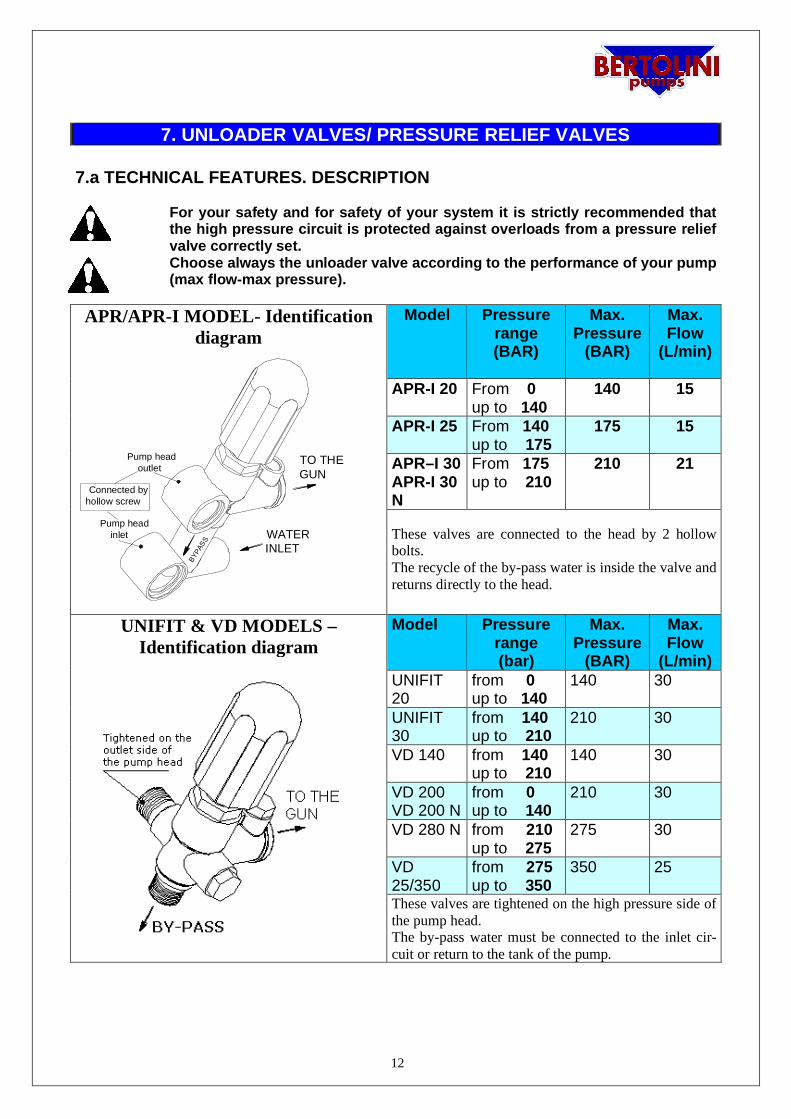
For your safety and for safety of your system it is strictly recommended thatthe high pressure circuit is protected against overloads from a pressure reliefvalve correctly set.Choose always the unloader valve according to the performance of your pump(max flow-max pressure).
APR/APR-I MODEL- Identificationdiagram
BYPA
SS
TO THEGUN
WATERINLET
Pump head outlet
Pump head inlet
Connected byhollow screw
Model Pressurerange(BAR)
Max.Pressure
(BAR)
Max.Flow
(L/min)
APR-I 20 From 0up to 140
140 15
APR-I 25 From 140up to 175
175 15
APR–I 30APR-I 30N
From 175up to 210
210 21
These valves are connected to the head by 2 hollowbolts.The recycle of the by-pass water is inside the valve andreturns directly to the head.
UNIFIT & VD MODELS –Identification diagram
Model Pressurerange(bar)
Max.Pressure
(BAR)
Max.Flow
(L/min)UNIFIT20
from 0up to 140
140 30
UNIFIT30
from 140up to 210
210 30
VD 140 from 140up to 210
140 30
VD 200VD 200 N
from 0up to 140
210 30
VD 280 N from 210up to 275
275 30
VD25/350
from 275up to 350
350 25
These valves are tightened on the high pressure side ofthe pump head.The by-pass water must be connected to the inlet cir-cuit or return to the tank of the pump.
13
Setting of unloader valve must be done only by skilled personnel. All instruc-tions indicated by manufacturer must be observed.
Bertolini valves have been designed to ensure the best efficiency of the system protection and longlife of the pump.When the gun is open they work as pressure relief valves, they return to by-pass the amount ofwater in excess, at the setting pressure of the valve.If, for example, while working with a system set at 140 bar, the nozzle is clogged, the valve is par-tially opening and is returning to by-pass the amount of water that cannot go through the nozzle, sothat the pressure is not overcoming the setting value of the valve.Instead, when the gun is shut off, the valve is completely opening and is returning to by-pass thewhole amount of water.Bertolini valves are conceived in a way that, in these conditions, only the part of the circuit betweenthe valve and the gun remains on pressure, while the water recycling is done at a very low pres-sure (less than 5 bar -72 P.S.I.).In this way the pump is turning on with a minimal absorption of power and the recycling water iswarming up very slowly, providing extended life of the pump and of the seals.The maximum working time in by-pass must never exceed 5 minutes. Otherwise seals will wearquickly.
All Bertolini valves are tested and adjusted in the factory at the max. pressure indicatedin the chart.
When necessary, the system’s manufacturer should REDUCE the max. setting pres-sure of the valve in order to conform to the max. operating pressure of the pump.
DO NOT BOOST THE SETTING PRESSURE
THE REDUCTION OF THE MAX. SETTING PRESSURE VALUE IS ONLY TO BECARRIED OUT BY THE SYSTEM’S MANUFACTURER. THE FOLLOWINGINSTRUCTIONS MUST BE RESPECTED.
UNLOADER VALVES - STARTING PROCEDURE
7.b PRESSURE ADJUSTING
1. Check on the pump label the data and the correct setting pressure.2. Make certain that nozzle mounted on the lance has the correct size (see nozzles chart)and is not clogged.3. Connect the high pressure hose to the pump and check the connection between hoseand gun.4. Connect pump to the inlet circuit.5. If you have a double lance carry the knob to low pressure position.
14
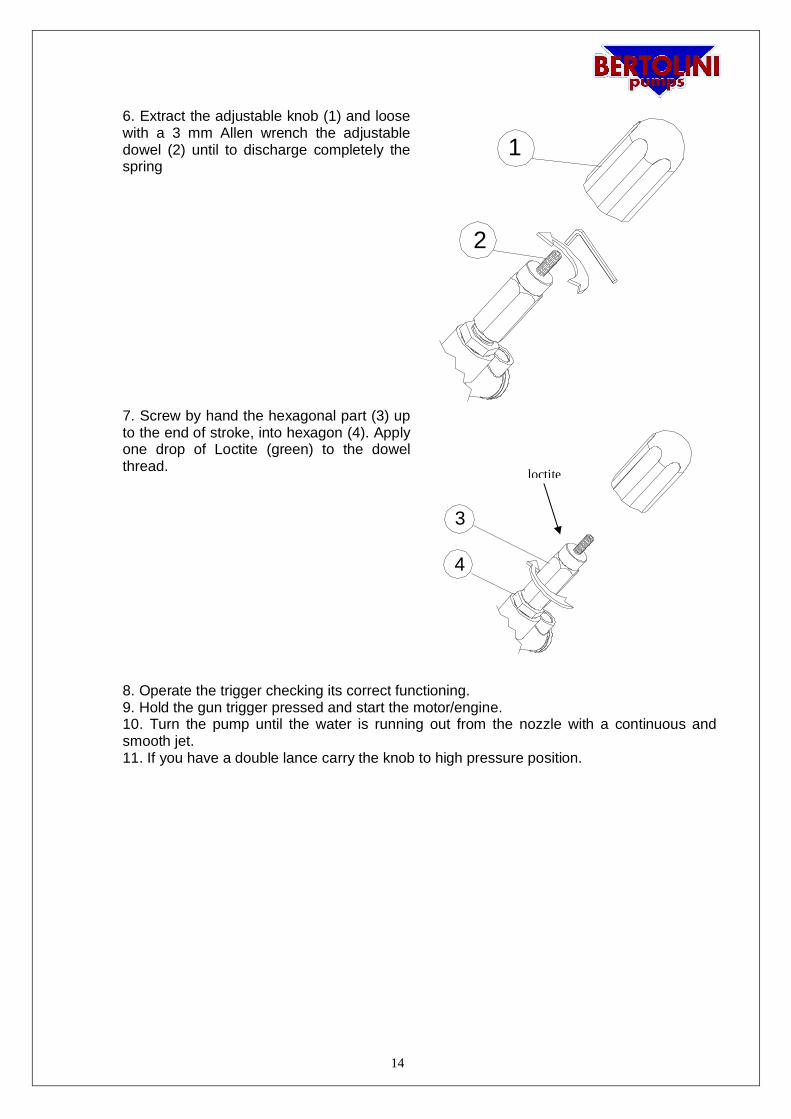
6. Extract the adjustable knob (1) and loosewith a 3 mm Allen wrench the adjustabledowel (2) until to discharge completely thespring
1
2
7. Screw by hand the hexagonal part (3) upto the end of stroke, into hexagon (4). Applyone drop of Loctite (green) to the dowelthread.
4
3
8. Operate the trigger checking its correct functioning.9. Hold the gun trigger pressed and start the motor/engine.10. Turn the pump until the water is running out from the nozzle with a continuous andsmooth jet.11. If you have a double lance carry the knob to high pressure position.
loctite
15
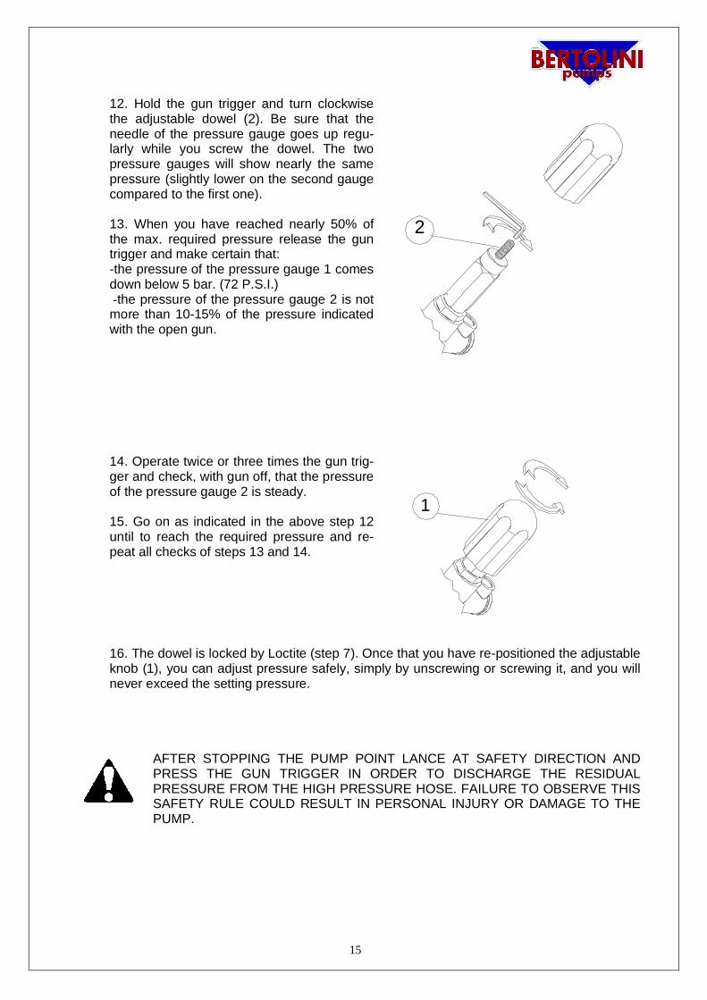
12. Hold the gun trigger and turn clockwisethe adjustable dowel (2). Be sure that theneedle of the pressure gauge goes up regu-larly while you screw the dowel. The twopressure gauges will show nearly the samepressure (slightly lower on the second gaugecompared to the first one).
13. When you have reached nearly 50% ofthe max. required pressure release the guntrigger and make certain that:-the pressure of the pressure gauge 1 comesdown below 5 bar. (72 P.S.I.) -the pressure of the pressure gauge 2 is notmore than 10-15% of the pressure indicatedwith the open gun.
2
14. Operate twice or three times the gun trig-ger and check, with gun off, that the pressureof the pressure gauge 2 is steady.
15. Go on as indicated in the above step 12until to reach the required pressure and re-peat all checks of steps 13 and 14.
1
16. The dowel is locked by Loctite (step 7). Once that you have re-positioned the adjustableknob (1), you can adjust pressure safely, simply by unscrewing or screwing it, and you willnever exceed the setting pressure.
AFTER STOPPING THE PUMP POINT LANCE AT SAFETY DIRECTION ANDPRESS THE GUN TRIGGER IN ORDER TO DISCHARGE THE RESIDUALPRESSURE FROM THE HIGH PRESSURE HOSE. FAILURE TO OBSERVE THISSAFETY RULE COULD RESULT IN PERSONAL INJURY OR DAMAGE TO THEPUMP.
16
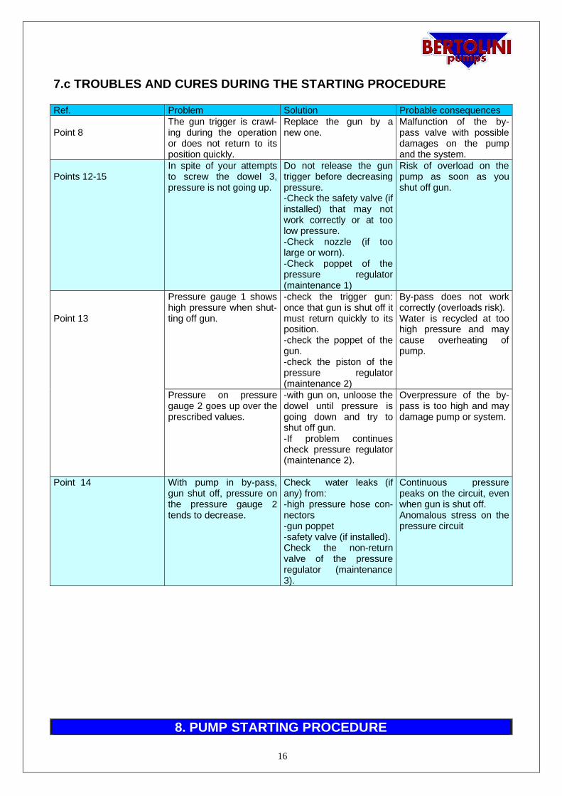
7.c TROUBLES AND CURES DURING THE STARTING PROCEDURE
8. PUMP STARTING PROCEDURE
Ref. Problem Solution Probable consequences
Point 8The gun trigger is crawl-ing during the operationor does not return to itsposition quickly.
Replace the gun by anew one.
Malfunction of the by-pass valve with possibledamages on the pumpand the system.
Points 12-15In spite of your attemptsto screw the dowel 3,pressure is not going up.
Do not release the guntrigger before decreasingpressure.-Check the safety valve (ifinstalled) that may notwork correctly or at toolow pressure.-Check nozzle (if toolarge or worn).-Check poppet of thepressure regulator(maintenance 1)
Risk of overload on thepump as soon as youshut off gun.
Point 13
Pressure gauge 1 showshigh pressure when shut-ting off gun.
-check the trigger gun:once that gun is shut off itmust return quickly to itsposition.-check the poppet of thegun.-check the piston of thepressure regulator(maintenance 2)
By-pass does not workcorrectly (overloads risk).Water is recycled at toohigh pressure and maycause overheating ofpump.
Pressure on pressuregauge 2 goes up over theprescribed values.
-with gun on, unloose thedowel until pressure isgoing down and try toshut off gun.-If problem continuescheck pressure regulator(maintenance 2).
Overpressure of the by-pass is too high and maydamage pump or system.
Point 14 With pump in by-pass,gun shut off, pressure onthe pressure gauge 2tends to decrease.
Check water leaks (ifany) from:-high pressure hose con-nectors-gun poppet-safety valve (if installed).Check the non-returnvalve of the pressureregulator (maintenance3).
Continuous pressurepeaks on the circuit, evenwhen gun is shut off.Anomalous stress on thepressure circuit
17
Before starting pump check to make sure that:
· The suction hose is not damaged or bent;· The suction strainer is clean;· The nozzle is unclogged. It must be of proper size and replaced when worn.· Prime the pump, gun on, to allow air to escape; a quick priming of the pump prevents malfunc-
tions of the pumping elements (packings, pistons);· The water flow is open or the tube is plunged in the supplying container.· Do not run the pump dry, it may cause irreparable damages to the packings and sealing com-
ponents.
9. OPERATION
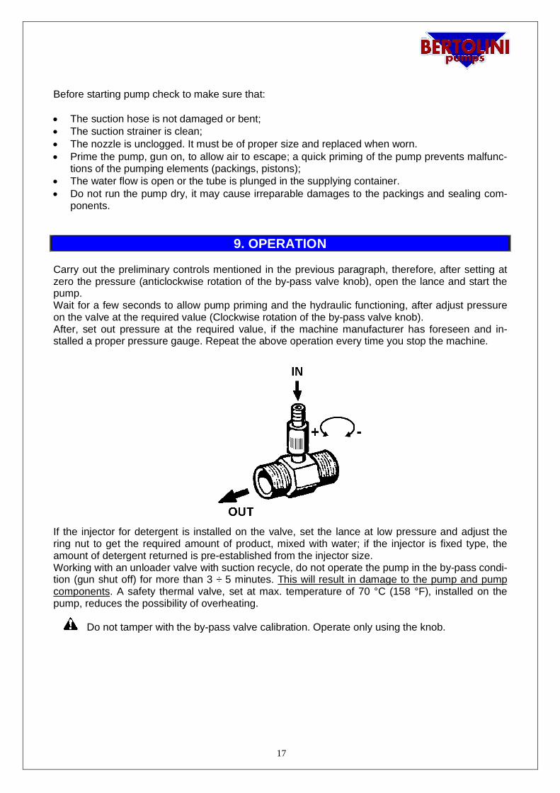
Carry out the preliminary controls mentioned in the previous paragraph, therefore, after setting atzero the pressure (anticlockwise rotation of the by-pass valve knob), open the lance and start thepump.Wait for a few seconds to allow pump priming and the hydraulic functioning, after adjust pressureon the valve at the required value (Clockwise rotation of the by-pass valve knob).After, set out pressure at the required value, if the machine manufacturer has foreseen and in-stalled a proper pressure gauge. Repeat the above operation every time you stop the machine.
If the injector for detergent is installed on the valve, set the lance at low pressure and adjust thering nut to get the required amount of product, mixed with water; if the injector is fixed type, theamount of detergent returned is pre-established from the injector size.Working with an unloader valve with suction recycle, do not operate the pump in the by-pass condi-tion (gun shut off) for more than 3 ÷ 5 minutes. This will result in damage to the pump and pumpcomponents. A safety thermal valve, set at max. temperature of 70 °C (158 °F), installed on thepump, reduces the possibility of overheating.
Do not tamper with the by-pass valve calibration. Operate only using the knob.
18
9.1 OPERATION WITH DETERGENT
CAUTION· Use only the detergents recommended by the Producer of the machine incorporating the
pump. In particular, never suck fluids containing solvents, petrol, thinners, acetone and combus-tible oil, because the sprayed product is highly flammable, explosive and toxic.
· Carefully read all prescriptions and warnings on the label of the detergents in order to takethe suitable measure not to generate dangers for you and for the environment.
· Preserve the detergents in a safe place that cannot be reached by children.In case of contact with eyes, wash immediately with water and apply to a doctor by bringingwith you the detergent package.
· In case of ingestion, do not induce vomiting and immediately apply to a doctor by bringingwith you the detergent package.
To carry out correctly what described below, refer also to the use and maintenancemanual of the machine incorporating the pump.
a) Set the pump pressure below 30 bar/435 psi (for instance, in case of a water clean-er, this can be obtained by activating the low pressure operation on a lance with thesuitable nozzle holder).
b) If there is the possibility to adjust the detergent suction, operate on the knob: byscrewing it you decrease the flow of the sucked detergent and by unscrewing it youincrease it.
WARNINGTo avoid deposits, after the detergent use it is a good habit to wash the passage ducts by suckingsome water.
CAUTION: The high pressure jet, if used incorrectly, could result in personal injuryor damages to the environment. Too high pressure may damage the objects thatyou require to wash; we recommend to carry out operating tests (working pressure,distance of the nozzle from the object, etc.) on waste materials.
Idromeccanica Bertolini S.p.A. declines any civil or criminal liability for damage or acci-dents to persons or property as may arise from the improper use of the pump, relevant ac-cessories and motors/engines driving the pump.
19
10. SHUT DOWN PROCEDURE- CLEANING AND STANDSTILL
After use, if chemical products have been used, run the pump with clean water for a few minutes.Then empty the pump, by running the pump for about 20 seconds, without water supply.If freezing conditions are likely to be met, drain completely of pumped fluid or flush with anti-freezeliquid.
· In no case hoses must have fluid on pressure when stopping the pump.· Carry out the cleaning and maintenance operations recommended by the Producer of the
machine incorporating the pump.Therefore make sure that:- you have closed the water supply and then stop the pump.- you have set the delivery pressure at zero bar as described in paragraph B.
11. STARTING PROCEDURE AFTER LONG TIME OF NO OPERATION
For pumps working in negative inlet pressure from tank, if they have not run for a long time, prim-ing could be difficult.For quick priming, force inlet pressure (1÷ 3 bar), connecting for example water supply, and startthe pump. Once priming is done and the operation is regular, reset the connection in negativepressure.
In some pumps, when starting-up (first minutes), you can notice a little leak of water from the seals;this is a normal factor because, specially in very hot climate conditions, the seals tend to get dryand they loose their elasticity. After working a few minutes, they re-absorb the normal humidity,and they will return to normal conditions.
CAUTION!: Do not run the pump dry for a long time; this will result in premature pump failure. Theinlet plumbing without elbows, of adequate diameter and fitted with an appropriate strainer makespriming easier. A quick priming of the pump prolongs pumping components and packings life.
12. LUBRICATION
Before each start-up, check the pump crankcase for a proper oil level; proper oil level is indicatedby the red dot in the sight-glass or between the high and low marks on the dipstick (incorporated inthe plug).
Use only oil SAE 75W-90
LUBRICANTSCASTROL TAF-X 75W-90PERSIAN SINTEX GEAR 75W-90STILMOIL GEARING SUPER SYNT 75W-90VALVOLINE SYNPOWER GEAR OIL 75W-90
20
Change oil after the first 50 hours and then change oil every 500 hours (200 hours for pumps over240 Bar) or every 6 months or every time you find quality degradation to the touch.If the pump is used in humid climates, it is necessary to change oil periodically, and anyway, be-fore finding out the emulsion with condensation (typical off/white colour).If the pump is used at high temperatures, it is necessary to change oil more frequently in order toprevent the deterioration of lubricating properties.When changing oil (500 hours or emulsion of water or 200 hours), clean crankcase inside remov-ing all impurities, use degreasing products to be spread by brush and consequent disposal.
CAUTION: Operating pump with emulsified oil (with water, condensation, etc.) will reduce the lubri-cation of the moving parts and consequently will result in overheating and premature failures to thekinematic mechanism, Idromeccanica Bertolini cannot be hold liable.
Protect the environment from liquids contained in the pump.Collect residues and dispose of them regularly.
13. ROUTINE MAINTENANCE
At each use check oil level and state.Check every 50 hours:
a) suction filter cleaning.b) The suction circuit (no leaks) and conditions of the hydraulic connections.c) Check fixing conditions of the pump to the motor / engine and to the structure.
Checks must be carried out daily if the pump is working in presence of vibrations
IMPORTANT CONDITION!: Nozzle is subject to wear, so it must be replaced everytime that your pump will not reach the required pressure; in fact, when worn, the actualflow rate is increasing and pressure is decreasing.
21
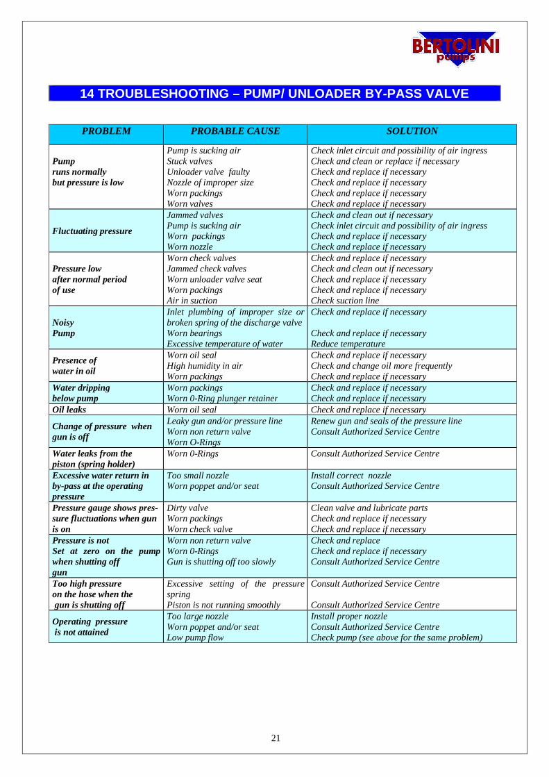
14 TROUBLESHOOTING – PUMP/ UNLOADER BY-PASS VALVE
PROBLEM PROBABLE CAUSE SOLUTION
Pumpruns normallybut pressure is low
Pump is sucking airStuck valvesUnloader valve faultyNozzle of improper sizeWorn packingsWorn valves
Check inlet circuit and possibility of air ingressCheck and clean or replace if necessaryCheck and replace if necessaryCheck and replace if necessaryCheck and replace if necessaryCheck and replace if necessary
Fluctuating pressure
Jammed valvesPump is sucking airWorn packingsWorn nozzle
Check and clean out if necessaryCheck inlet circuit and possibility of air ingressCheck and replace if necessaryCheck and replace if necessary
Pressure lowafter normal periodof use
Worn check valvesJammed check valvesWorn unloader valve seatWorn packingsAir in suction
Check and replace if necessaryCheck and clean out if necessaryCheck and replace if necessaryCheck and replace if necessaryCheck suction line
NoisyPump
Inlet plumbing of improper size orbroken spring of the discharge valveWorn bearingsExcessive temperature of water
Check and replace if necessary
Check and replace if necessaryReduce temperature
Presence ofwater in oil
Worn oil sealHigh humidity in airWorn packings
Check and replace if necessaryCheck and change oil more frequentlyCheck and replace if necessary
Water drippingbelow pump
Worn packingsWorn 0-Ring plunger retainer
Check and replace if necessaryCheck and replace if necessary
Oil leaks Worn oil seal Check and replace if necessary
Change of pressure whengun is off
Leaky gun and/or pressure lineWorn non return valveWorn O-Rings
Renew gun and seals of the pressure lineConsult Authorized Service Centre
Water leaks from thepiston (spring holder)
Worn 0-Rings Consult Authorized Service Centre
Excessive water return inby-pass at the operatingpressure
Too small nozzleWorn poppet and/or seat
Install correct nozzleConsult Authorized Service Centre
Pressure gauge shows pres-sure fluctuations when gunis on
Dirty valveWorn packingsWorn check valve
Clean valve and lubricate partsCheck and replace if necessaryCheck and replace if necessary
Pressure is notSet at zero on the pumpwhen shutting offgun
Worn non return valveWorn 0-RingsGun is shutting off too slowly
Check and replaceCheck and replace if necessaryConsult Authorized Service Centre
Too high pressureon the hose when the gun is shutting off
Excessive setting of the pressurespringPiston is not running smoothly
Consult Authorized Service Centre
Consult Authorized Service Centre
Operating pressure is not attained
Too large nozzleWorn poppet and/or seatLow pump flow
Install proper nozzleConsult Authorized Service CentreCheck pump (see above for the same problem)
22
15- LIMITED WARRANTY
The liability of the manufacturer under the period of warranty (12 months from date of manufactur-er’s shipment) is limited to the replacement of the parts that, upon examination, appear in Bertoli-ni’s satisfaction to have been defective in material or workmanship.This warranty is valid only when the fault is ascertained by its technicians, it shall not apply to anypump which have been repaired or altered to adversely affect the performance or reliability of thepump.This warranty does not apply to malfunctions caused by fault or negligence of the buyer or thirdparty, to the improper use of the pump, to failures reported to the manufacturer after the warrantyperiod has expired, or to the normal wear of the component parts of the products such as seals,cups, O-Rings, valves, etc.Costs of labour, packages and transport costs are at the Buyer’s charges . Products, after receipt pfwritten factory approval, must be returned complete with all parts and not tampered. Otherwisewarranty is void.
This warranty is subject to the following conditions:
- Pump must be used within the specifications indicated in this manual and in the manual of themachine where the pump is installed. A safety valve must be correctly installed in the system.
- The warranty is void if pump is operating without sufficient fluid to the pump (cavitation).- The warranty is void if pump is operating without oil in the crankcase.- Protect pump from freezing. Do not store in area with freezing conditions. Drain completely of
pumped fluid. Flush with antifreeze. Do not store or operate in excessively high temperature areasor without proper ventilation.
- The warranty is void if installation is not correct.- The warranty is void if the recommended maintenance instructions are not observed.- Different uses of the pump than the ones mentioned in the paragraph “Intended Use”.- The warranty is void if the pump use does not conform to the specific current safety standards and
if the machine incorporating the pump is without CE marking.-Use of non-original spare parts or even not suited for the pump model.
USE OF OTHER THAN BERTOLINI PARTS VOIDS THE WARRANTY
ANY PRODUCT MUST BE RETURNED FREE BERTOLINI FACTORYPARTS RETURNED MUST HAVE FACTORY APPROVAL DOCUMENTATION PRIOR TORETURN.
23
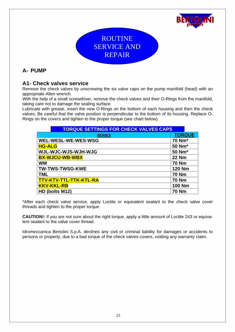
A- PUMP
A1- Check valves serviceRemove the check valves by unscrewing the six valve caps on the pump manifold (head) with anappropriate Allen wrench.With the help of a small screwdriver, remove the check valves and their O-Rings from the manifold,taking care not to damage the sealing surface.Lubricate with grease, insert the new O-Rings on the bottom of each housing and then the checkvalves. Be careful that the valve position is perpendicular to the bottom of its housing. Replace O-Rings on the covers and tighten to the proper torque (see chart below).
TORQUE SETTINGS FOR CHECK VALVES CAPSSERIES TORQUE
WEL-WESL-WE-WES-WSG 70 Nm*HG-ALG 50 Nm*WJL-WJC-WJS-WJH-WJG 50 Nm*BX-WJCU-WB-WBX 22 NmWM 70 NmTW-TWS-TWSG-KWE 120 NmTML 70 NmTTV-KTV-TTL-TTK-KTL-RA 70 NmKKV-KKL-RB 100 NmHD (bolts M12) 70 Nm
*After each check valve service, apply Loctite or equivalent sealant to the check valve coverthreads and tighten to the proper torque.
CAUTION!: If you are not sure about the right torque, apply a little amount of Loctite 243 or equiva-lent sealant to the valve cover thread.
Idromeccanica Bertolini S.p.A. declines any civil or criminal liability for damages or accidents topersons or property, due to a bad torque of the check valves covers, voiding any warranty claim.
ROUTINESERVICE AND
REPAIR
24
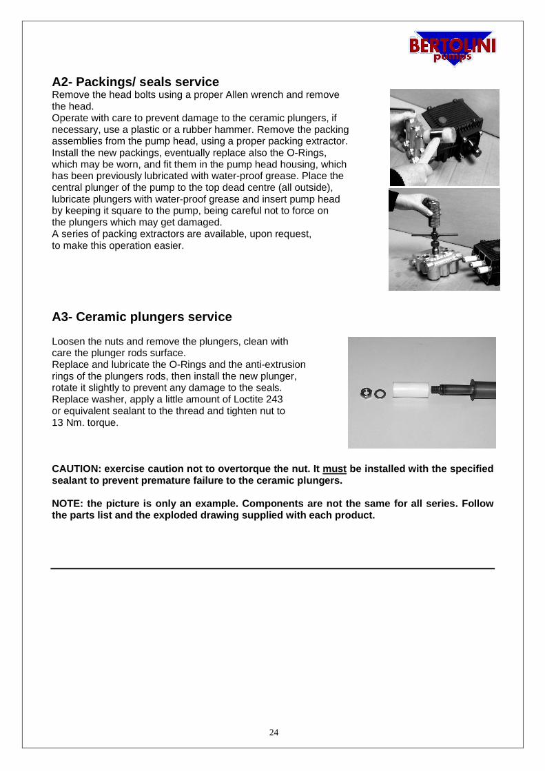
A2- Packings/ seals serviceRemove the head bolts using a proper Allen wrench and removethe head.Operate with care to prevent damage to the ceramic plungers, ifnecessary, use a plastic or a rubber hammer. Remove the packingassemblies from the pump head, using a proper packing extractor.Install the new packings, eventually replace also the O-Rings,which may be worn, and fit them in the pump head housing, whichhas been previously lubricated with water-proof grease. Place thecentral plunger of the pump to the top dead centre (all outside),lubricate plungers with water-proof grease and insert pump headby keeping it square to the pump, being careful not to force onthe plungers which may get damaged.A series of packing extractors are available, upon request,to make this operation easier.
A3- Ceramic plungers service
Loosen the nuts and remove the plungers, clean withcare the plunger rods surface.Replace and lubricate the O-Rings and the anti-extrusionrings of the plungers rods, then install the new plunger,rotate it slightly to prevent any damage to the seals.Replace washer, apply a little amount of Loctite 243or equivalent sealant to the thread and tighten nut to13 Nm. torque.
CAUTION: exercise caution not to overtorque the nut. It must be installed with the specifiedsealant to prevent premature failure to the ceramic plungers.
NOTE: the picture is only an example. Components are not the same for all series. Followthe parts list and the exploded drawing supplied with each product.
25
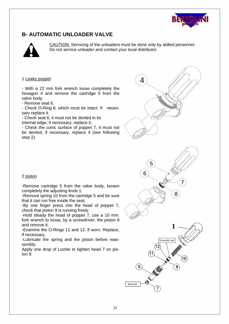
B- AUTOMATIC UNLOADER VALVE
CAUTION: Servicing of the unloaders must be done only by skilled personnel.Do not service unloader and contact your local distributor.
1 Leaky poppet
- With a 22 mm fork wrench loose completely thehexagon 4 and remove the cartridge 5 from thevalve body.- Remove seat 6.- Check O-Ring 8, which must be intact. If neces-sary replace it.- Check seat 6, it must not be dented in itsinternal edge, if necessary, replace it.- Check the conic surface of poppet 7, it must notbe dented, if necessary, replace it (see followingstep 2)
2 piston
-Remove cartridge 5 from the valve body, loosencompletely the adjusting knob 1.-Remove spring 10 from the cartridge 5 and be surethat it can run free inside the seat.-By one finger press into the head of poppet 7,check that piston 9 is running freely.-Hold steady the head of poppet 7, use a 10 mm.fork wrench to loose, by a screwdriver, the piston 9and remove it.-Examine the O-Rings 11 and 12, if worn. Replace,if necessary.-Lubricate the spring and the piston before reas-sembly.Apply one drop of Loctite to tighten head 7 on pis-ton 9.
4
5
67
8
1
26
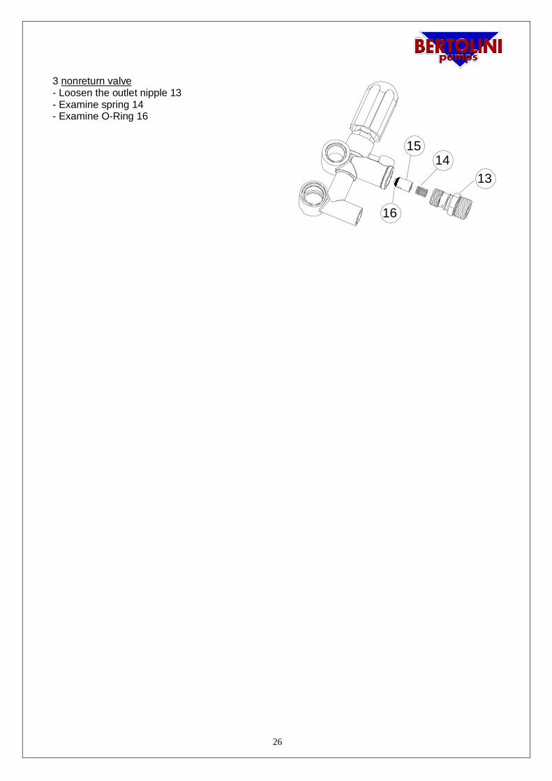
3 nonreturn valve- Loosen the outlet nipple 13- Examine spring 14- Examine O-Ring 16
1314
15
16
27
Manufacturer’s DeclarationMachines Directive 2006/42/CE (Attachment II point B)
Idromeccanica Bertolini S.p.A.:declares under its sole responsibility that the pump series
ALG – BXH-F – BXG – WJC-U – WBL –WBL-F –WBS – WBS-F – WBC – WBC-F – WBH – WBH-F – WBG – WBG-W – WBX – WBXL-F – WBXG – WML – WML-F – WMC – WMC-F – WMS –WMS-F – WMH –WMH-F – WMG – WMG-W – TM-S – TML – TML-F – TML-HP – TMS-HP –
TMS – TMS-F – TMH – TMH-F – TMG – AKML – AKMS – TTV – KTV – KKV – HD – TTL – TTK –KTL – KKL –RA-S – RB-S – RAL – RAS – RAL-H – RAS-H – RB – RBL – RBS
with the serial number(to be filled in by purchaser according to identification label)
-is manufactured to be incorporated in a machine or to be assembled with other equipment to forma machine provided for by Directive 2006/42/CE;
-the producer of the machine, that incorporates the pump, is the only one responsible of the ac-cordance in every point to this Directive’s standards.
Therefore Idromeccanica Bertolini S.p.A. declares that the above pump must not be put into opera-tion up to the machine in which it will be built-in will be identified and will be declared in compliance
with the Directive’s standards 2006/42/CE.
Reggio Emilia 10.10.11Managing Director- L. Quaretti
28