piston engines
TRANSCRIPT
1
Dept. of Energy Technology, KTH - Stockholm
Piston Engines for power plant applications
Sustainable Power Generation (SPG) MJ2405 Miro Petrov
2
Dept. of Energy Technology, KTH - Stockholm
Division of piston (reciprocating) engines per type of fuel and working fluid
• Steam Engine! the birth of the industrial society
• Internal Combustion Engines (ICE) = open gas cycle– Spark Ignition (SI); – Compression Ignition/Diesel (CI); – Dual-fuel (gas-diesel) engines (DF or GD); – Homogeneous Charge Compression Ignition (HCCI)
• Stirling Engine = closed gas cycle(externally-heated closed-cycle piston engine)
3
Dept. of Energy Technology, KTH - Stockholm
Piston Engine Applications
• Stationary - for driving machinery or electrical generators; or as back-up drives
• Propulsion / transportation -automotive, rail, airborne, marine, construction & agricultural vehicles, etc.
• Small engines to drive hand-operateddevices or appliances - loan mower, chainsaw, small back-up power units, etc.
4
Dept. of Energy Technology, KTH - Stockholm
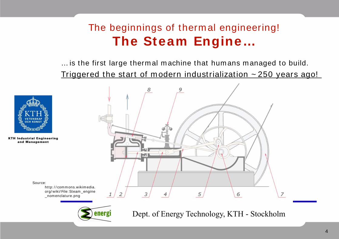
The beginnings of thermal engineering! The Steam Engine…
… is the first large thermal machine that humans managed to build.Triggered the start of modern industrialization ~250 years ago!
Source: http://commons.wikimedia.org/wiki/File:Steam_engine_nomenclature.png
5
Dept. of Energy Technology, KTH - Stockholm
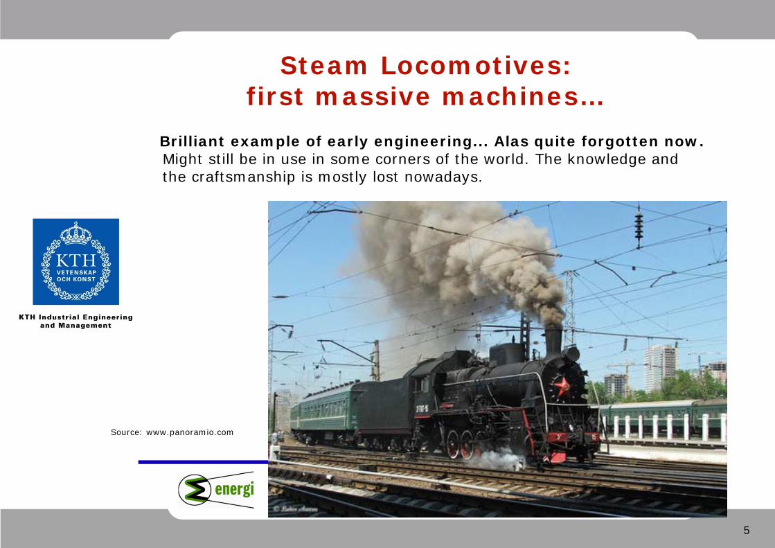
Steam Locomotives: first massive machines…
Brilliant example of early engineering... Alas quite forgotten now. Might still be in use in some corners of the world. The knowledge and the craftsmanship is mostly lost nowadays.
Source: www.panoramio.com
6
Dept. of Energy Technology, KTH - Stockholm
Quick Historical Review
• James Watt – the commercial steam engine in the 1780’s..
• Jean Joseph Etienne Lenoir – the first commercial gas-burning engine in mid 1800’s
• Nicolaus A. Otto and Eugen Langen – patented and marketed the first modern-type gasoline SI engine in 1867
• Alphonse Beau de Rochas (1861) – described theoretically the modern four-stroke SI engine before Otto
• Karl Benz, Wilhelm Maybach, Gottlieb Daimler, etc.. – further perfected various crucial components and production techniques for commercial engines
• Rudolf Diesel – patented the diesel engine in 1892
• Felix Wankel – the rotating-piston ICE in the 1950-ies
• Robert Stirling – patented the Stirling engine already in 1818
7
Dept. of Energy Technology, KTH - Stockholm
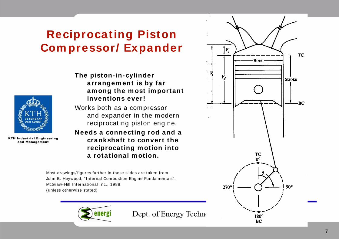
Reciprocating Piston Compressor/Expander
Most drawings/figures further in these slides are taken from: John B. Heywood, ”Internal Combustion Engine Fundamentals”, McGraw-Hill International Inc., 1988. (unless otherwise stated)
The piston-in-cylinder arrangement is by far among the most important inventions ever!
Works both as a compressor and expander in the modern reciprocating piston engine.
Needs a connecting rod and a crankshaft to convert the reciprocating motion into a rotational motion.

8
Dept. of Energy Technology, KTH - Stockholm
Classification of IC Engines
• Otto (SI) or Diesel (CI) cycle
• Four-stroke or Two-stroke
• One cylinder or Multicylinder
• Multicylinder arrangement: in-line, V-type, W-type, boxer
• Naturally-aspirated or forced-charged
• Water-cooled, Air-cooled, Oil-cooled
• Rotary ICE (rotating piston) – the Wankel engine
9
Dept. of Energy Technology, KTH - Stockholm
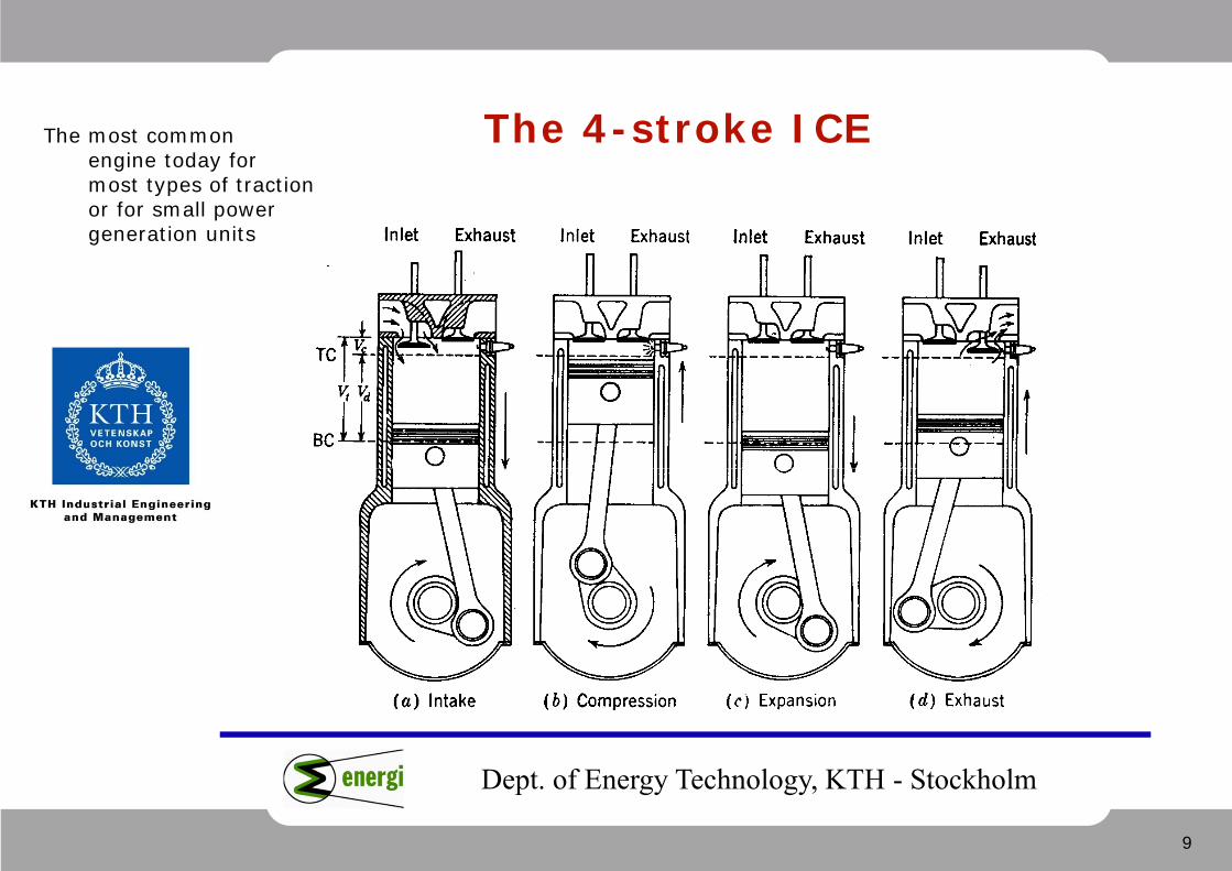
The 4-stroke ICE The most common engine today for most types of traction or for small power generation units
10
Dept. of Energy Technology, KTH - Stockholm
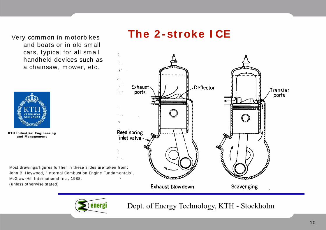
The 2-stroke ICE Very common in motorbikes and boats or in old small cars, typical for all small handheld devices such as a chainsaw, mower, etc.
Most drawings/figures further in these slides are taken from: John B. Heywood, ”Internal Combustion Engine Fundamentals”, McGraw-Hill International Inc., 1988. (unless otherwise stated)
11
Dept. of Energy Technology, KTH - Stockholm
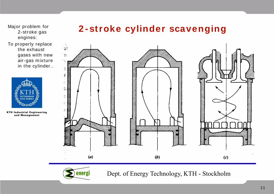
2-stroke cylinder scavengingMajor problem for 2-stroke gas engines:
To properly replacethe exhaustgases with new air-gas mixturein the cylinder..

12
Dept. of Energy Technology, KTH - Stockholm
Typical ICE
Channels for cooling water (jacket water)
The typical car engine: 4-stroke, 4-in-line cylinders, overhead camshaft..
13
Dept. of Energy Technology, KTH - Stockholm
Main parameters of reciprocating engines
• Cylinder displacement (cylinder volume = combustion chamber volume)
• Number of cylinders
• Rotational speed (revolutions per minute – rpm – also defining the number of work strokes per minute)
• Number of work strokes per cycle (2 or 4)
• Compression ratio
• Mean Effective Pressure (break mean effective pressure)
14
Dept. of Energy Technology, KTH - Stockholm
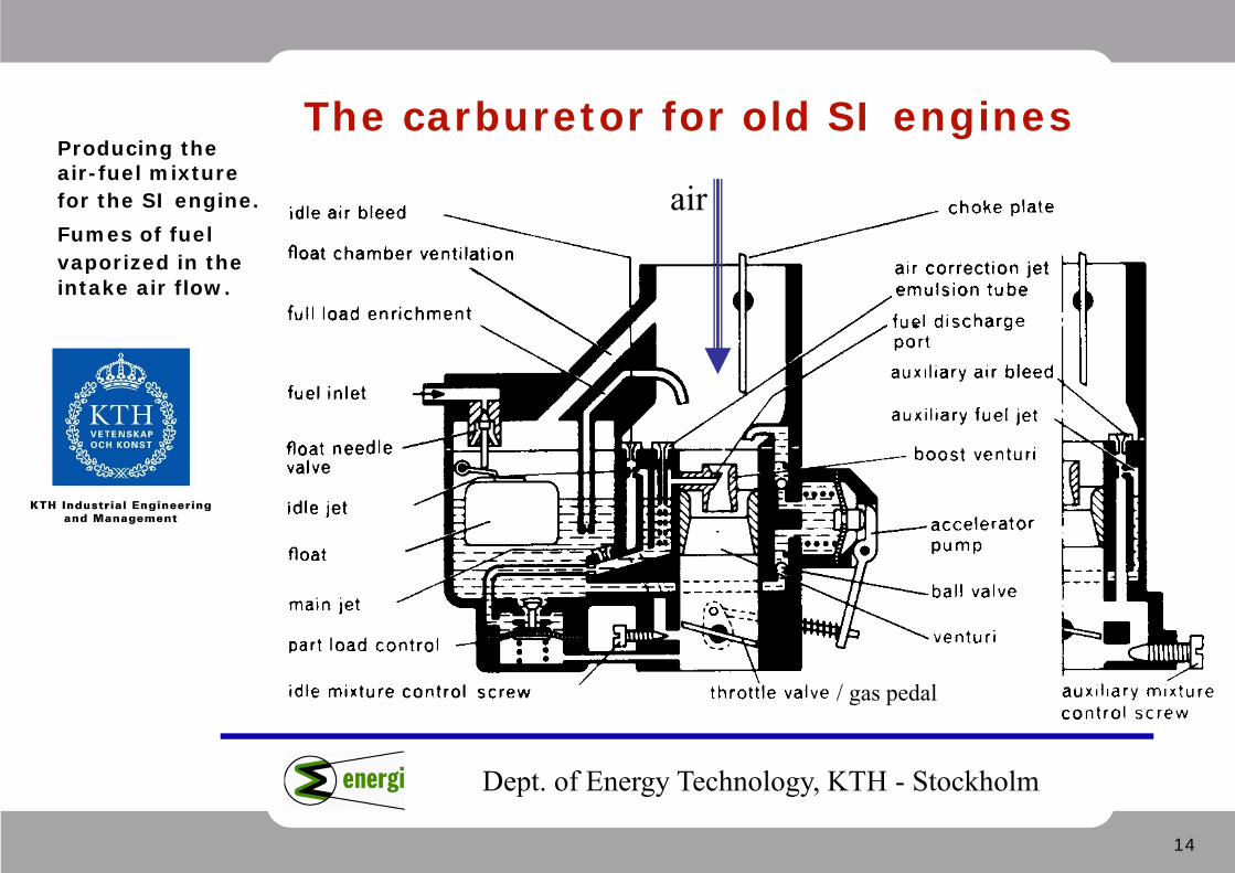
The carburetor for old SI engines
air
/ gas pedal
Producing the air-fuel mixture for the SI engine.Fumes of fuel vaporized in theintake air flow.
15
Dept. of Energy Technology, KTH - Stockholm
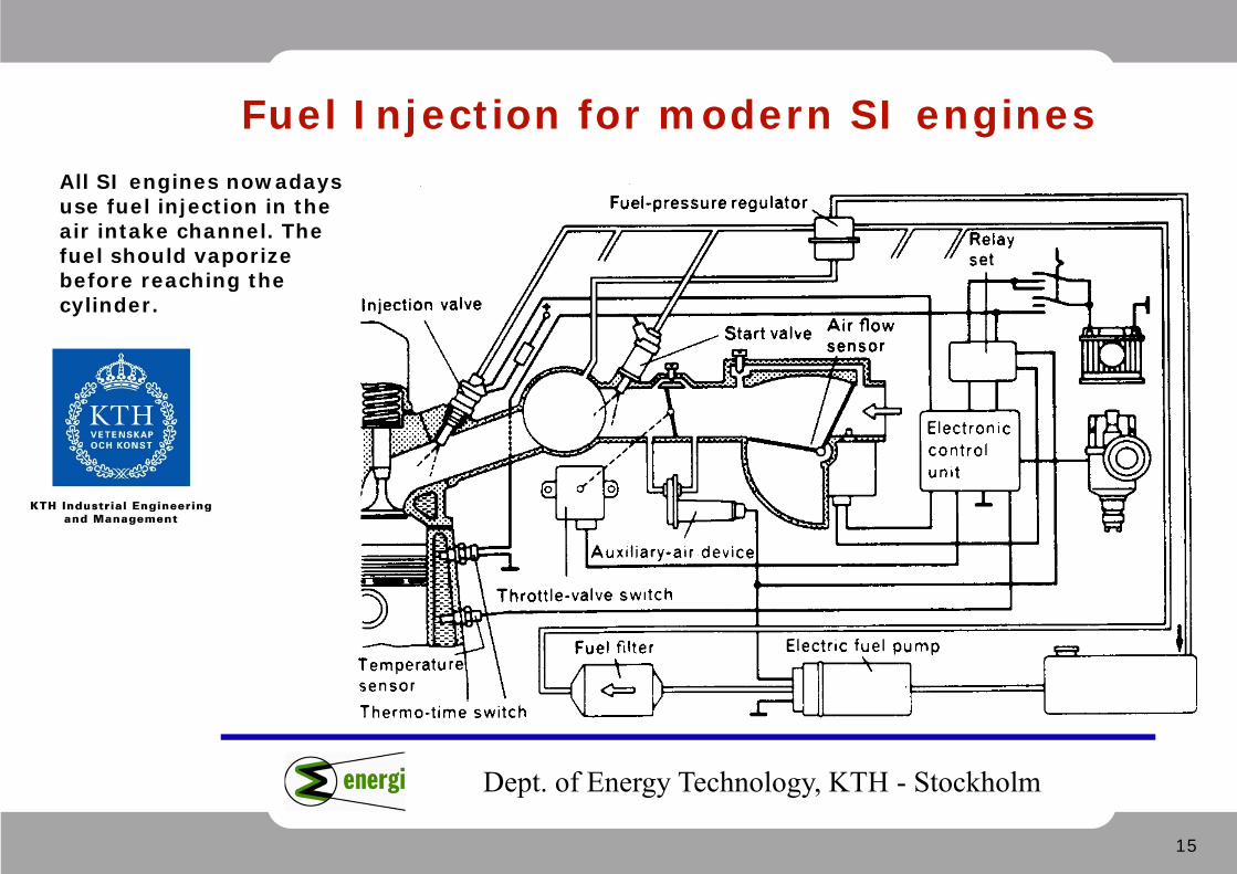
Fuel Injection for modern SI enginesAll SI engines nowadays use fuel injection in the air intake channel. The fuel should vaporize before reaching the cylinder.
16
Dept. of Energy Technology, KTH - Stockholm
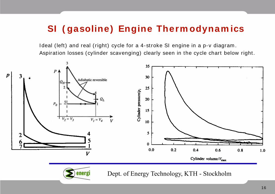
SI (gasoline) Engine ThermodynamicsIdeal (left) and real (right) cycle for a 4-stroke SI engine in a p-v diagram. Aspiration losses (cylinder scavenging) clearly seen in the cycle chart below right.
17
Dept. of Energy Technology, KTH - Stockholm
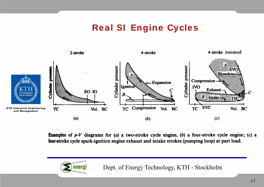
Real SI Engine Cycles
zoomed
18
Dept. of Energy Technology, KTH - Stockholm
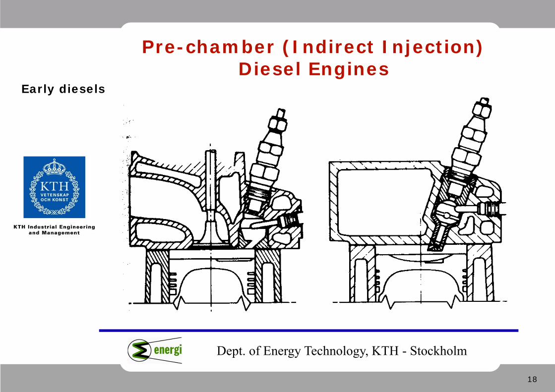
Pre-chamber (Indirect Injection) Diesel Engines
Early diesels
19
Dept. of Energy Technology, KTH - Stockholm
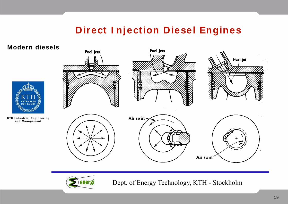
Direct Injection Diesel EnginesModern diesels
20
Dept. of Energy Technology, KTH - Stockholm
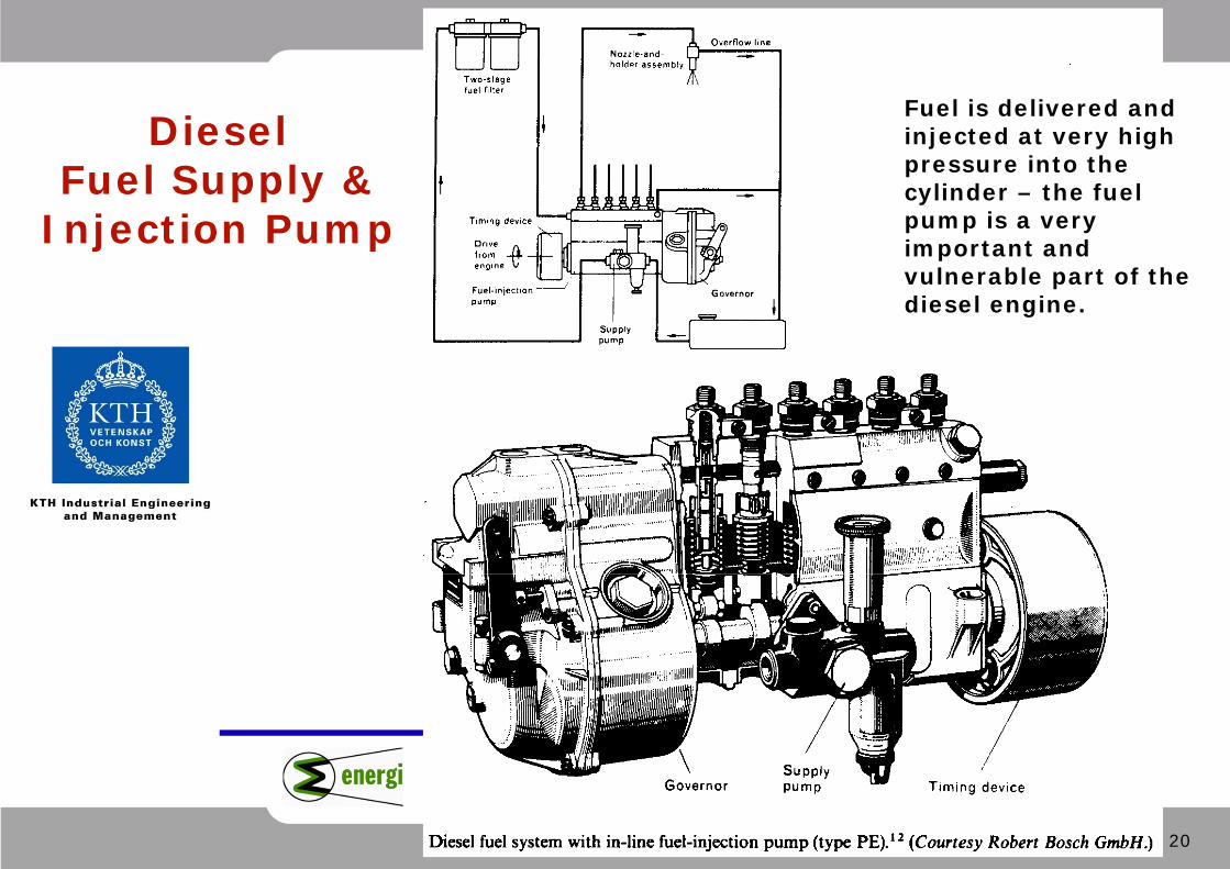
Diesel Fuel Supply &
Injection Pump
Fuel is delivered and injected at very high pressure into the cylinder – the fuel pump is a very important and vulnerable part of the diesel engine.
21
Dept. of Energy Technology, KTH - Stockholm
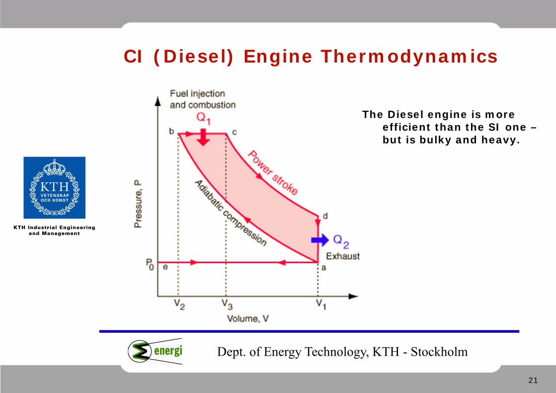
CI (Diesel) Engine Thermodynamics
The Diesel engine is more efficient than the SI one –but is bulky and heavy.
22
Dept. of Energy Technology, KTH - Stockholm
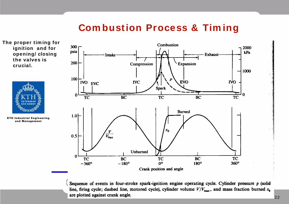
Combustion Process & TimingThe proper timing for
ignition and for opening/closing the valves is crucial.
23
Dept. of Energy Technology, KTH - Stockholm
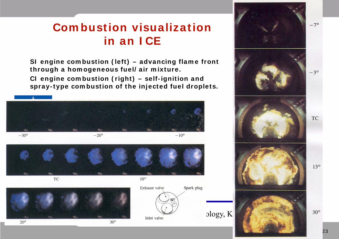
Combustion visualization in an ICE
SI engine combustion (left) – advancing flame front through a homogeneous fuel/air mixture. CI engine combustion (right) – self-ignition and spray-type combustion of the injected fuel droplets.

24
Dept. of Energy Technology, KTH - Stockholm
Combustion Efficiency
25
Dept. of Energy Technology, KTH - Stockholm
Environmental performance of IC engines
SI engines tend to produce unburned HC, CO, and NOx.
CI engines tend to produce lots of NOx and soot, but very little unburned HC or CO.
Possible solutions for improving the environmental profile: • Better control on fuel injection and ignition timing. • Better construction for proper fuel-air mixing. • Catalytic converters. • Exhaust gas recirculation. • Aftertreatment of exhaust gases with active De-NOx systems
(chemicals sprayed in the exhaust gas for heavy truck engines).
26
Dept. of Energy Technology, KTH - Stockholm
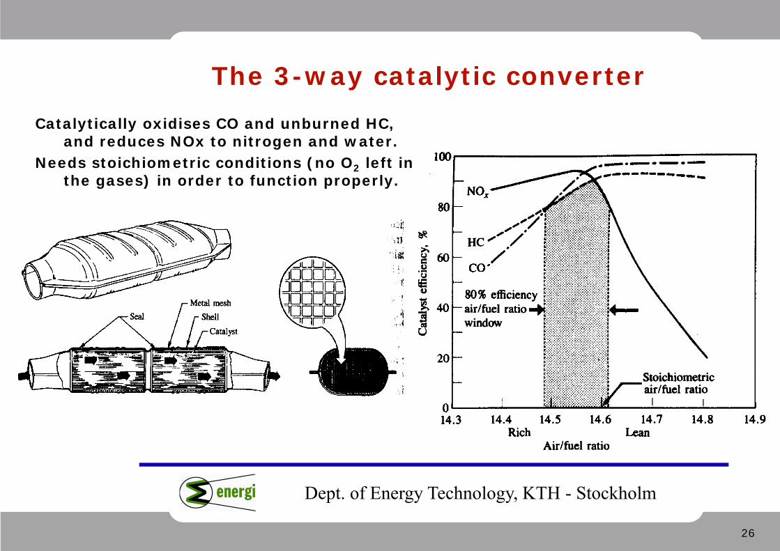
The 3-way catalytic converterCatalytically oxidises CO and unburned HC,
and reduces NOx to nitrogen and water.Needs stoichiometric conditions (no O2 left in
the gases) in order to function properly.
27
Dept. of Energy Technology, KTH - Stockholm
Improving ICE efficiency
Common gasoline car engines have typically an efficiency of <20% Diesel car engines can reach 25-30 % efficiencyTruck diesel engines are around 30-35% efficientLarge stationary or marine gas or diesel engines reach > 40%, some
close to 50% efficiency - the most efficient single-cycle!
Ways to improve the efficiency of internal combustion engines: • Lean-burn gas engines• Direct injection for car-size gasoline engines• Homogeneous-charge compression ignition (HCCI) approach • Stratified charge or dual-fuel combustion• Atkinson cycle or other optimized concepts• Turbocompound systems
28
Dept. of Energy Technology, KTH - Stockholm
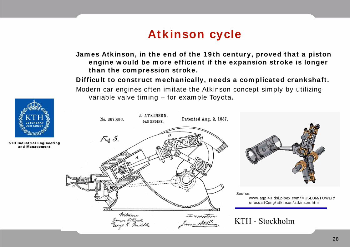
Atkinson cycleJames Atkinson, in the end of the 19th century, proved that a piston
engine would be more efficient if the expansion stroke is longer than the compression stroke.
Difficult to construct mechanically, needs a complicated crankshaft. Modern car engines often imitate the Atkinson concept simply by utilizing
variable valve timing – for example Toyota.
Source: www.aqpl43.dsl.pipex.com/MUSEUM/POWER/unusualICeng/atkinson/atkinson.htm
29
Dept. of Energy Technology, KTH - Stockholm
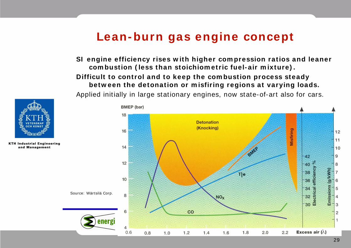
Lean-burn gas engine concept
SI engine efficiency rises with higher compression ratios and leaner combustion (less than stoichiometric fuel-air mixture).
Difficult to control and to keep the combustion process steady between the detonation or misfiring regions at varying loads.
Applied initially in large stationary engines, now state-of-art also for cars.
Source: Wärtsilä Corp.
30
Dept. of Energy Technology, KTH - Stockholm
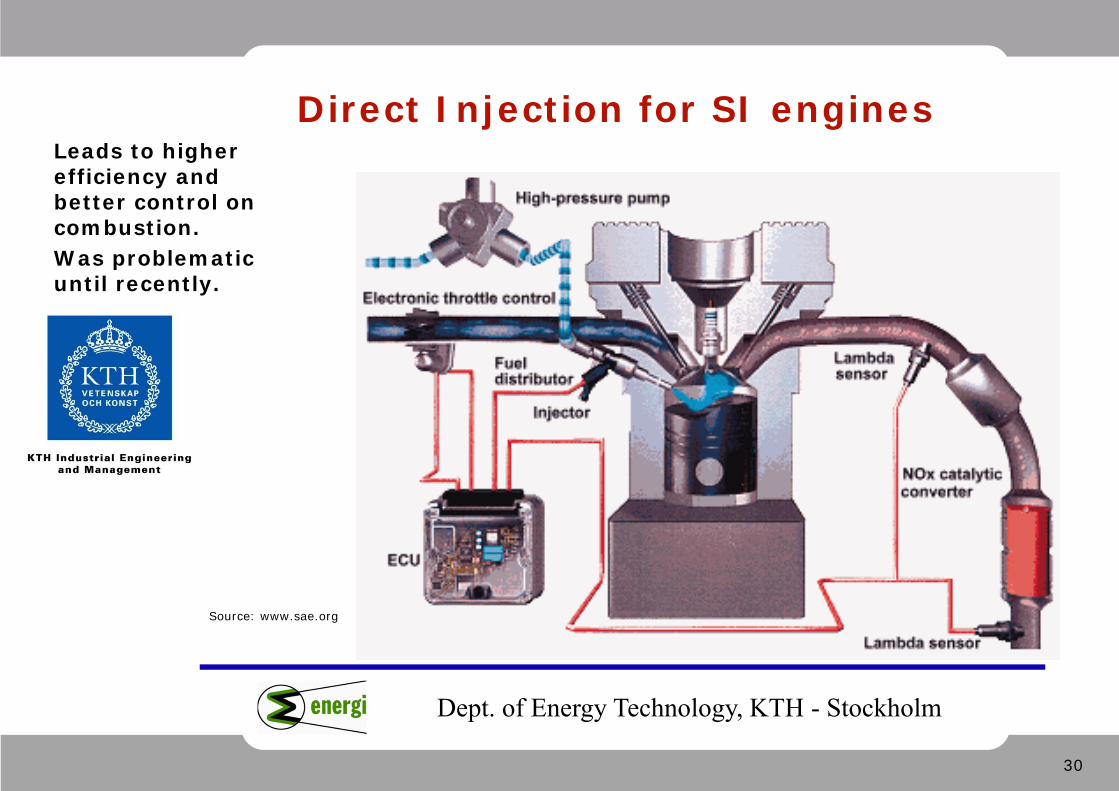
Direct Injection for SI engines
Source: www.sae.org
Leads to higher efficiency and better control on combustion. Was problematic until recently.
31
Dept. of Energy Technology, KTH - Stockholm
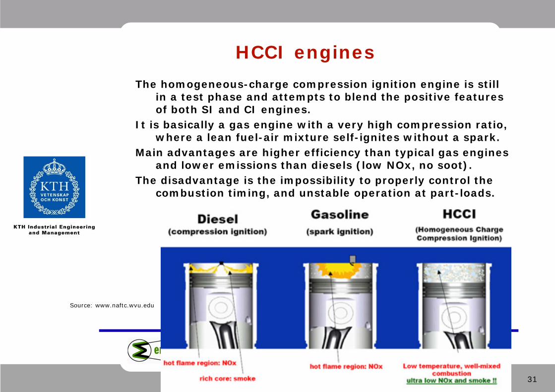
HCCI enginesThe homogeneous-charge compression ignition engine is still
in a test phase and attempts to blend the positive features of both SI and CI engines.
It is basically a gas engine with a very high compression ratio, where a lean fuel-air mixture self-ignites without a spark.
Main advantages are higher efficiency than typical gas engines and lower emissions than diesels (low NOx, no soot).
The disadvantage is the impossibility to properly control the combustion timing, and unstable operation at part-loads.
Source: www.naftc.wvu.edu
32
Dept. of Energy Technology, KTH - Stockholm
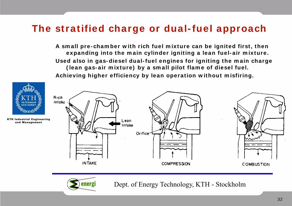
The stratified charge or dual-fuel approachA small pre-chamber with rich fuel mixture can be ignited first, then
expanding into the main cylinder igniting a lean fuel-air mixture. Used also in gas-diesel dual-fuel engines for igniting the main charge
(lean gas-air mixture) by a small pilot flame of diesel fuel. Achieving higher efficiency by lean operation without misfiring.
33
Dept. of Energy Technology, KTH - Stockholm
The Hybrid Vehicle concept
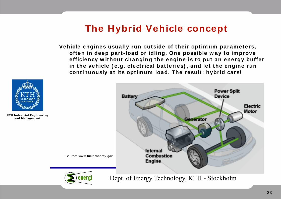
Vehicle engines usually run outside of their optimum parameters, often in deep part-load or idling. One possible way to improveefficiency without changing the engine is to put an energy bufferin the vehicle (e.g. electrical batteries), and let the engine runcontinuously at its optimum load. The result: hybrid cars!
Source: www.fueleconomy.gov
34
Dept. of Energy Technology, KTH - Stockholm
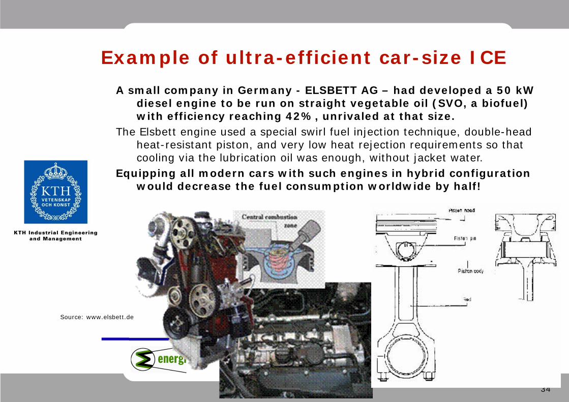
Example of ultra-efficient car-size ICEA small company in Germany - ELSBETT AG – had developed a 50 kW
diesel engine to be run on straight vegetable oil (SVO, a biofuel) with efficiency reaching 42%, unrivaled at that size.
The Elsbett engine used a special swirl fuel injection technique, double-headheat-resistant piston, and very low heat rejection requirements so thatcooling via the lubrication oil was enough, without jacket water.
Equipping all modern cars with such engines in hybrid configurationwould decrease the fuel consumption worldwide by half!
Source: www.elsbett.de

35
Dept. of Energy Technology, KTH - Stockholm
Forced Charging: Supercharger and Turbocharger
Forced charging (forced aspiration) delivers more air (= more oxygen) into the cylinder at higher pressure (>1 atm), allowing to produce more work by combusting more fuel in a given cylinder size, if compared to natural aspiration. Supercharger = air compressor driven by the engine shaft. Turbocharger = free-rotating turbocompressor driven by exhaust gases. Both can be used, but only the latter can bring along efficiency improvements!
36
Dept. of Energy Technology, KTH - Stockholm
Turbocompounding and Intercooling
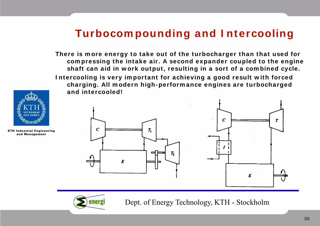
There is more energy to take out of the turbocharger than that used for compressing the intake air. A second expander coupled to the engine shaft can aid in work output, resulting in a sort of a combined cycle.
Intercooling is very important for achieving a good result with forced charging. All modern high-performance engines are turbocharged and intercooled!
37
Dept. of Energy Technology, KTH - Stockholm
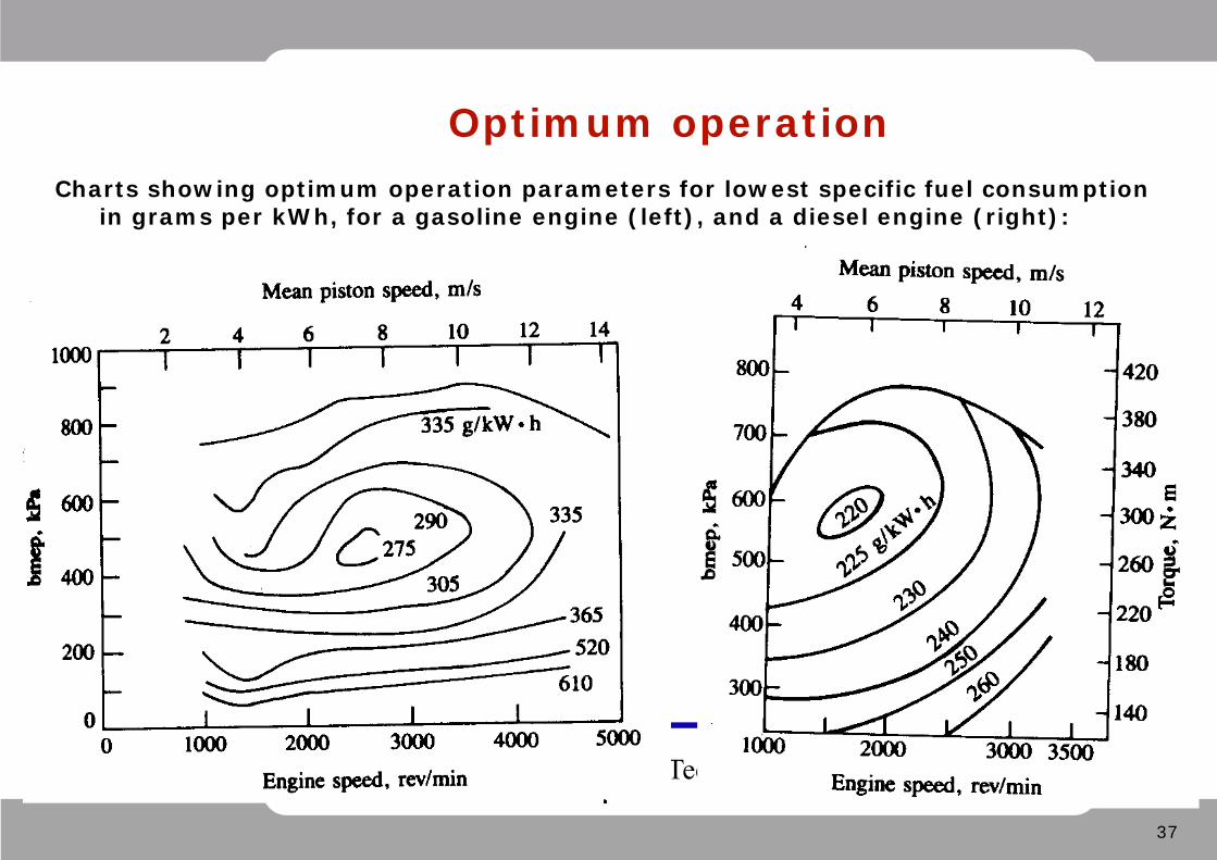
Optimum operationCharts showing optimum operation parameters for lowest specific fuel consumption
in grams per kWh, for a gasoline engine (left), and a diesel engine (right):
38
Dept. of Energy Technology, KTH - Stockholm
Advantages and Drawbacks of ICE
Very suitable for small- or medium-scale power generation. Their main advantages are: • High efficiency (higher than single-cycle gas turbines at same size); • Good part-load performance (better than turbines); • Somewhat lower cost & faster production/delivery than gas turbines; • Suitable for unit-wise installation – adding separate units for higher
total power output, allowing also for efficient part-load strategy.
Disadvantages of ICE, generally: • Low-temperature waste heat streams, not good for combined cycles; • Too large volumes and dimensions at high power outputs – engines
not feasible for power ratings higher than 40-50 MW per unit; • Low rpm or induced vibrations detrimental for certain applications; • May often have high maintenance costs.
39
Dept. of Energy Technology, KTH - Stockholm
Modern automotive engines
• SI engines – ECU-controlled direct injection with catalytic converter, exhaust gas recirculation, turbocharging with intercooling, electronic ignition…
• CI Engines – ECU-controlled direct injection of common-rail or injector-pump (pumpe-düse) type, multipoint injectors, multiple injections per stroke, exhaust gas recirculation, double turbochargers with intercooler, particle filter (soot filter)…
40
Dept. of Energy Technology, KTH - Stockholm
Electronic control of modern engines
Modern electronics (cheap and reliable) allow for better control on engine operational characteristics, optimising engine performance. The following major parameters are constantly monitored by sensors, sending signals to the ECU, deciding the amount of injected fuel and the ignition/injection timing:
• Intake air mass flow; • Intake air temperature and pressure; • Cooling water temperature; • Lambda-value (O2 remaining in exhaust gases); • Load on the engine at the given moment (gas pedal position); • Fuel type (for multifuel engines).
41
Dept. of Energy Technology, KTH - Stockholm
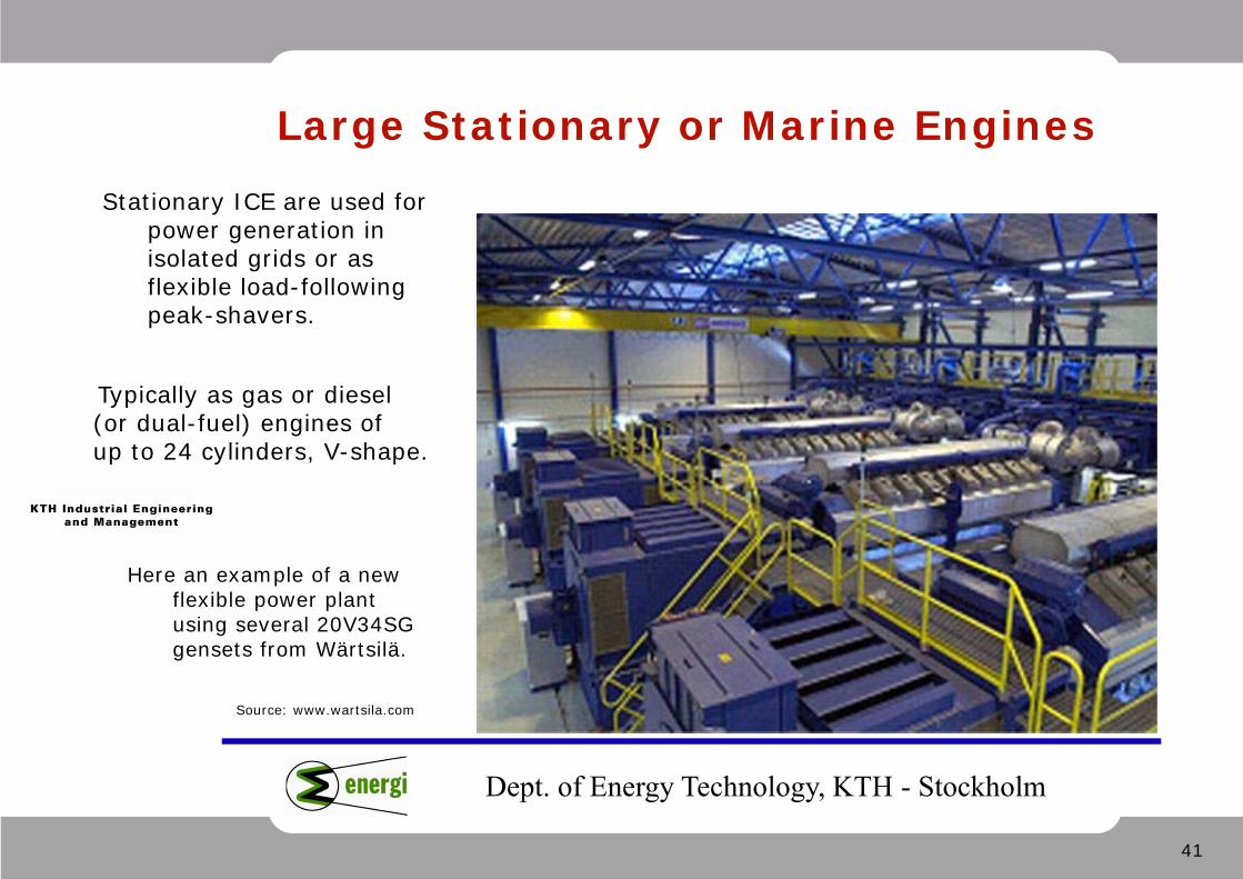
Large Stationary or Marine Engines
Source: www.wartsila.com
Stationary ICE are used for power generation in isolated grids or as flexible load-following peak-shavers.
Typically as gas or diesel (or dual-fuel) engines of up to 24 cylinders, V-shape.
Here an example of a new flexible power plant using several 20V34SG gensets from Wärtsilä.
42
Dept. of Energy Technology, KTH - Stockholm
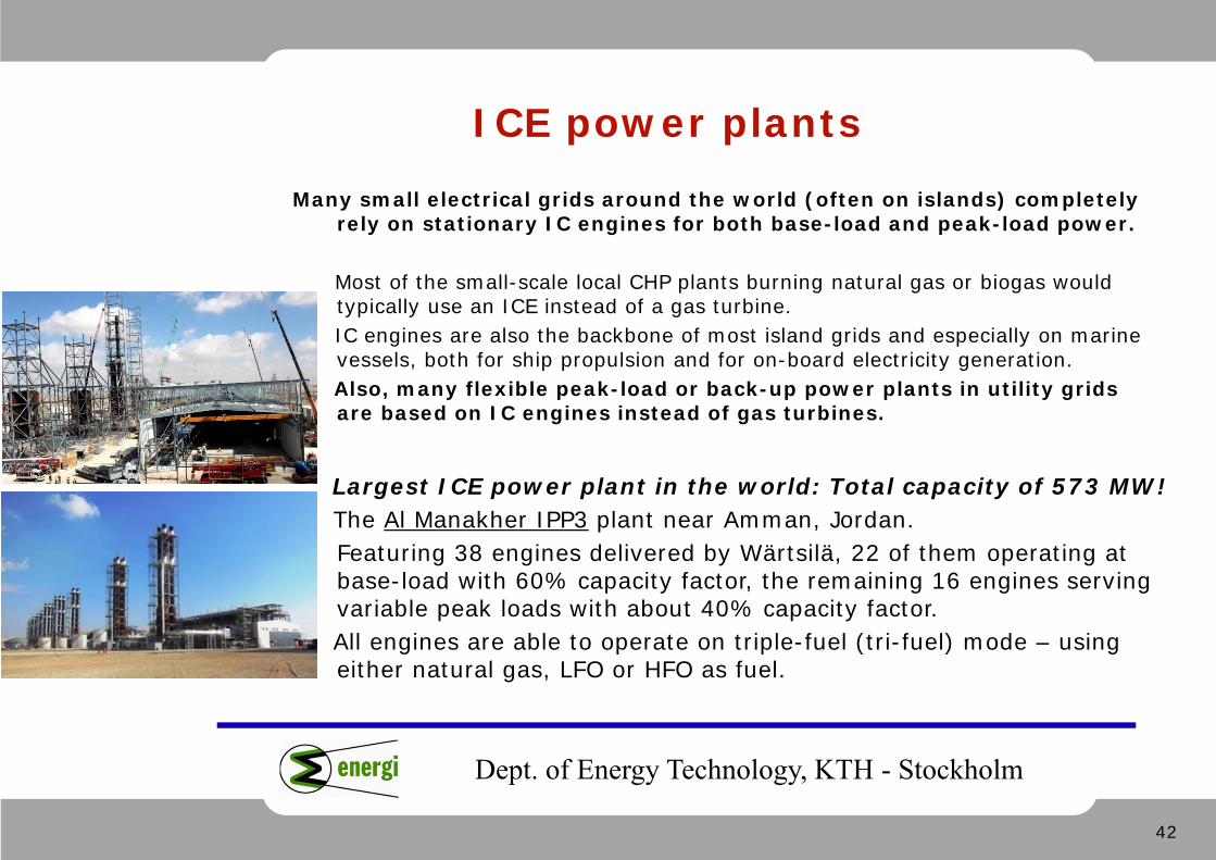
ICE power plants
Many small electrical grids around the world (often on islands) completelyrely on stationary IC engines for both base-load and peak-load power.
Most of the small-scale local CHP plants burning natural gas or biogas wouldtypically use an ICE instead of a gas turbine. IC engines are also the backbone of most island grids and especially on marine vessels, both for ship propulsion and for on-board electricity generation. Also, many flexible peak-load or back-up power plants in utility gridsare based on IC engines instead of gas turbines.
Largest ICE power plant in the world: Total capacity of 573 MW!The Al Manakher IPP3 plant near Amman, Jordan. Featuring 38 engines delivered by Wärtsilä, 22 of them operating at base-load with 60% capacity factor, the remaining 16 engines serving variable peak loads with about 40% capacity factor. All engines are able to operate on triple-fuel (tri-fuel) mode – using either natural gas, LFO or HFO as fuel.
43
Dept. of Energy Technology, KTH - Stockholm
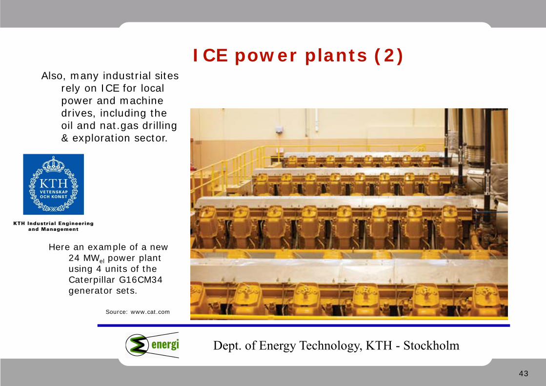
ICE power plants (2)
Source: www.cat.com
Also, many industrial sites rely on ICE for local power and machine drives, including the oil and nat.gas drilling & exploration sector.
Here an example of a new 24 MWel power plant using 4 units of the Caterpillar G16CM34 generator sets.

44
Dept. of Energy Technology, KTH - Stockholm
ICE power plants (3)Most importantly, ICE have
become a preferred choice in dynamic applications such as back-up and balancing power for grids dominated by renewable energy.
Source: www.powergen.gepower.com
Here are examples of some famous (now GE-owned) gensets by Waukesha and the very new Jenbacher J920. Above-right: a 51 MWel gas-fired plant using 6 units of the J920.
45
Dept. of Energy Technology, KTH - Stockholm
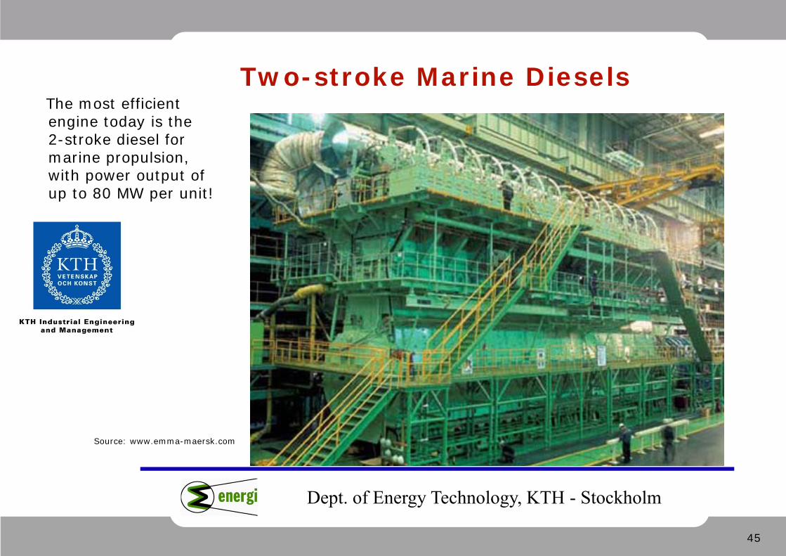
Two-stroke Marine Diesels
Source: www.emma-maersk.com
The most efficient engine today is the 2-stroke diesel for marine propulsion, with power output of up to 80 MW per unit!
46
Dept. of Energy Technology, KTH - Stockholm
Waste heat from an ICE
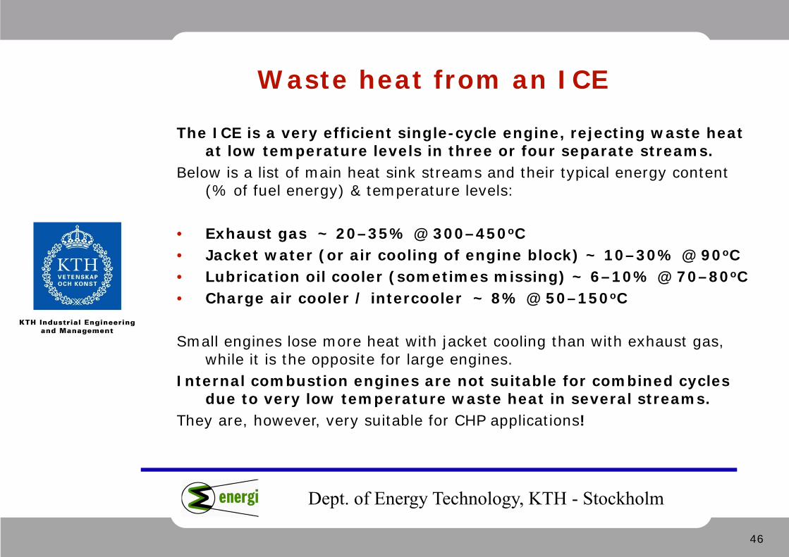
The ICE is a very efficient single-cycle engine, rejecting waste heat at low temperature levels in three or four separate streams.
Below is a list of main heat sink streams and their typical energy content (% of fuel energy) & temperature levels:
• Exhaust gas ~ 20–35% @ 300–450oC • Jacket water (or air cooling of engine block) ~ 10–30% @ 90oC • Lubrication oil cooler (sometimes missing) ~ 6–10% @ 70–80oC • Charge air cooler / intercooler ~ 8% @ 50–150oC
Small engines lose more heat with jacket cooling than with exhaust gas, while it is the opposite for large engines.
Internal combustion engines are not suitable for combined cycles due to very low temperature waste heat in several streams.
They are, however, very suitable for CHP applications!
47
Dept. of Energy Technology, KTH - Stockholm
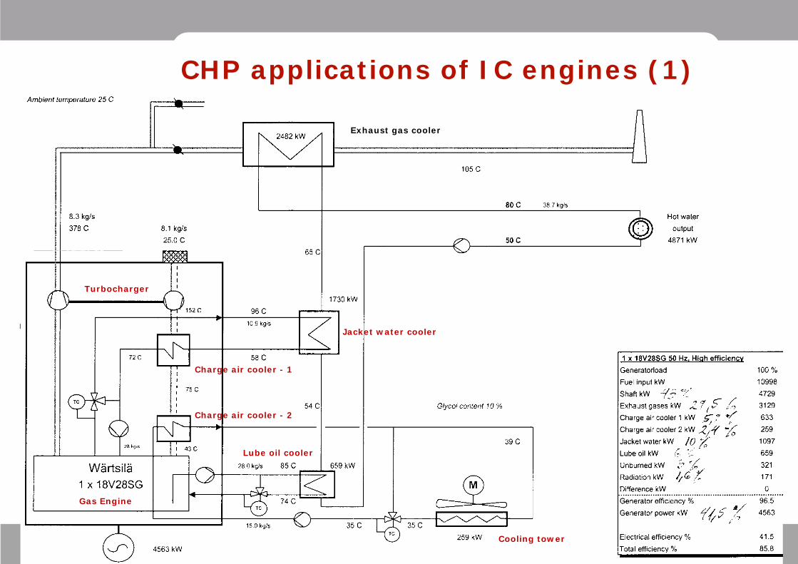
CHP applications of IC engines (1)
Cooling tower
Lube oil cooler
Jacket water cooler
Exhaust gas cooler
Charge air cooler - 1
Charge air cooler - 2
Turbocharger
Gas Engine
48
Dept. of Energy Technology, KTH - Stockholm
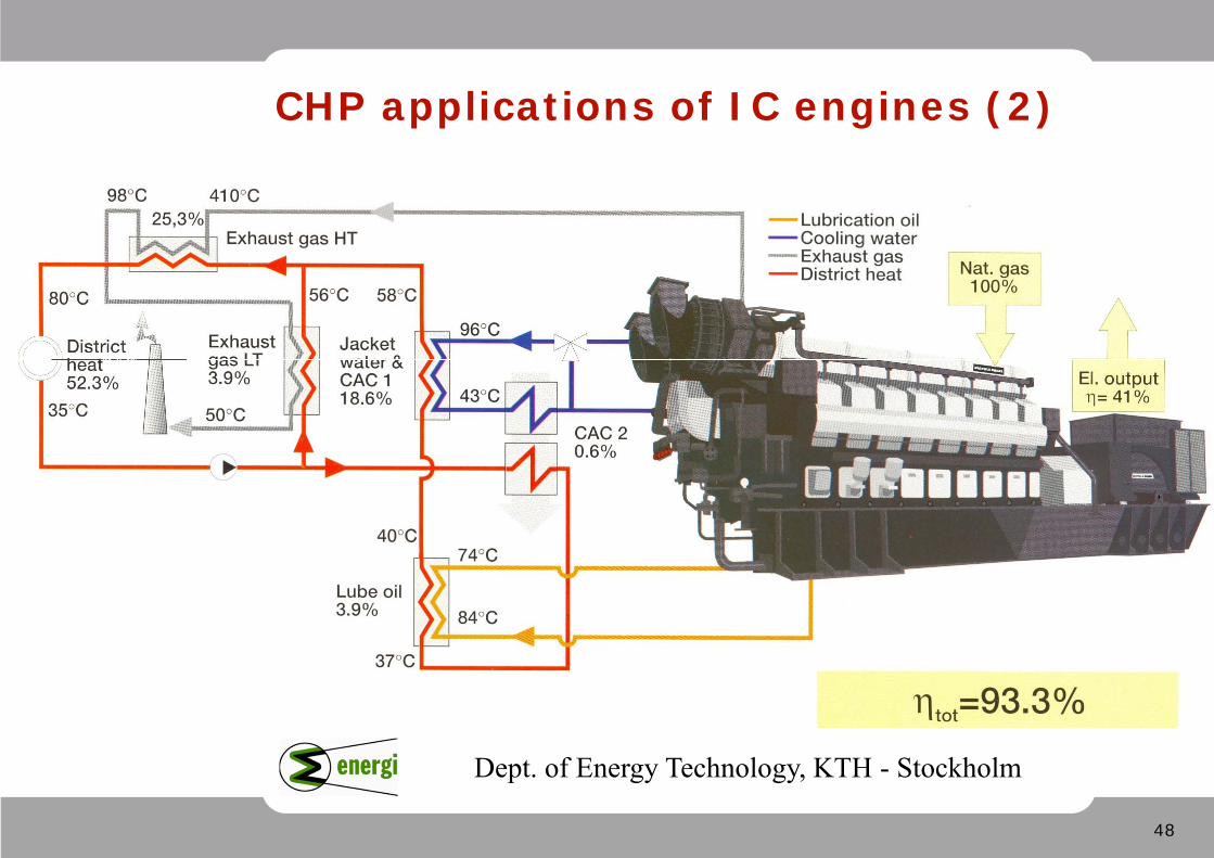
CHP applications of IC engines (2)
49
Dept. of Energy Technology, KTH - Stockholm
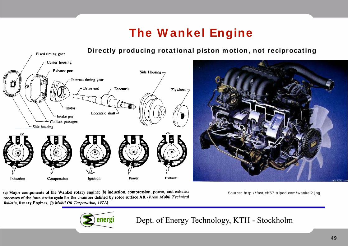
The Wankel Engine
Source: http://fastjeff57.tripod.com/wankel2.jpg
Directly producing rotational piston motion, not reciprocating
50
Dept. of Energy Technology, KTH - Stockholm
Wankel Engine: pros and cons
The idea of constructing a rotary-piston IC engine is very old. However, it is mechanically difficult to build.
Felix Wankel was the first to come up with a possible solution.
The Wankel engine is very fast and responsive, and achieves high rpm, but suffers from two main disadvantages:
• Large friction surfaces between piston and cylinder walls; • Large area of cylinder contact with cooling water.
This makes it far less efficient than conventional IC engines!
51
Dept. of Energy Technology, KTH - Stockholm
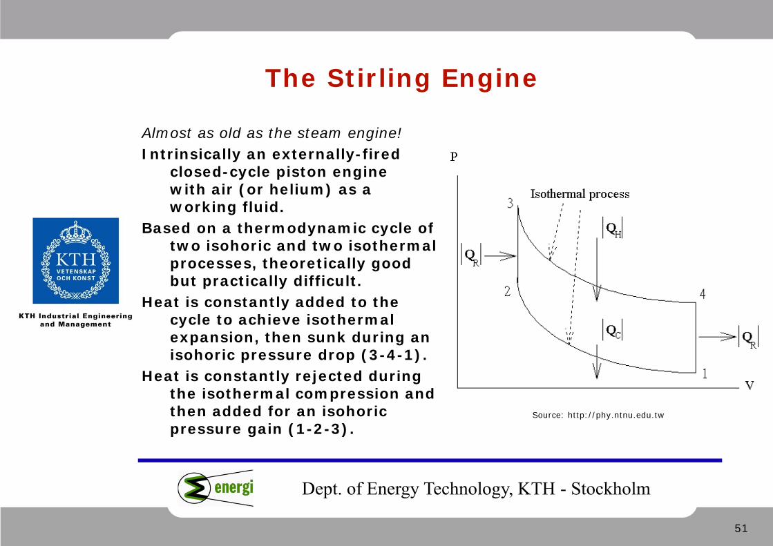
The Stirling Engine
Almost as old as the steam engine! Intrinsically an externally-fired
closed-cycle piston engine with air (or helium) as a working fluid.
Based on a thermodynamic cycle of two isohoric and two isothermal processes, theoretically good but practically difficult.
Heat is constantly added to the cycle to achieve isothermal expansion, then sunk during an isohoric pressure drop (3-4-1).
Heat is constantly rejected during the isothermal compression and then added for an isohoric pressure gain (1-2-3).
Source: http://phy.ntnu.edu.tw

52
Dept. of Energy Technology, KTH - Stockholm
Stirling Engine Configuration
Source: www.animatedengines.com
The working fluid is shuffled between the expansion and the compression cylinders, which have different sizes and stroke lengths. A regenerator in the middle improves the efficiency.
Hydrogen or helium gas (instead of air) is used as working fluid, for better heat exchange and compact size.
A practical Stirling engine works more like on adiabatic non-isothermal principles, losing its theoretical advantages.
It has a complex mechanical construction, and poor gas-to-gas heat exchange. It suffers also from material problems (limited temperatures) just like the steam cycles and gas turbines.
A reversed Stirling cycle can nicely function as a refrigerator!
53
Dept. of Energy Technology, KTH - Stockholm
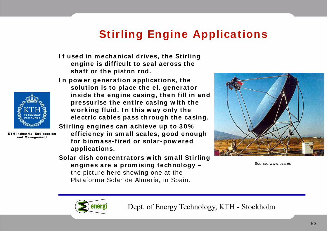
Stirling Engine Applications
Source: www.psa.es
If used in mechanical drives, the Stirling engine is difficult to seal across the shaft or the piston rod.
In power generation applications, the solution is to place the el. generator inside the engine casing, then fill in and pressurise the entire casing with the working fluid. In this way only the electric cables pass through the casing.
Stirling engines can achieve up to 30% efficiency in small scales, good enough for biomass-fired or solar-powered applications.
Solar dish concentrators with small Stirling engines are a promising technology –the picture here showing one at the Plataforma Solar de Almería, in Spain.