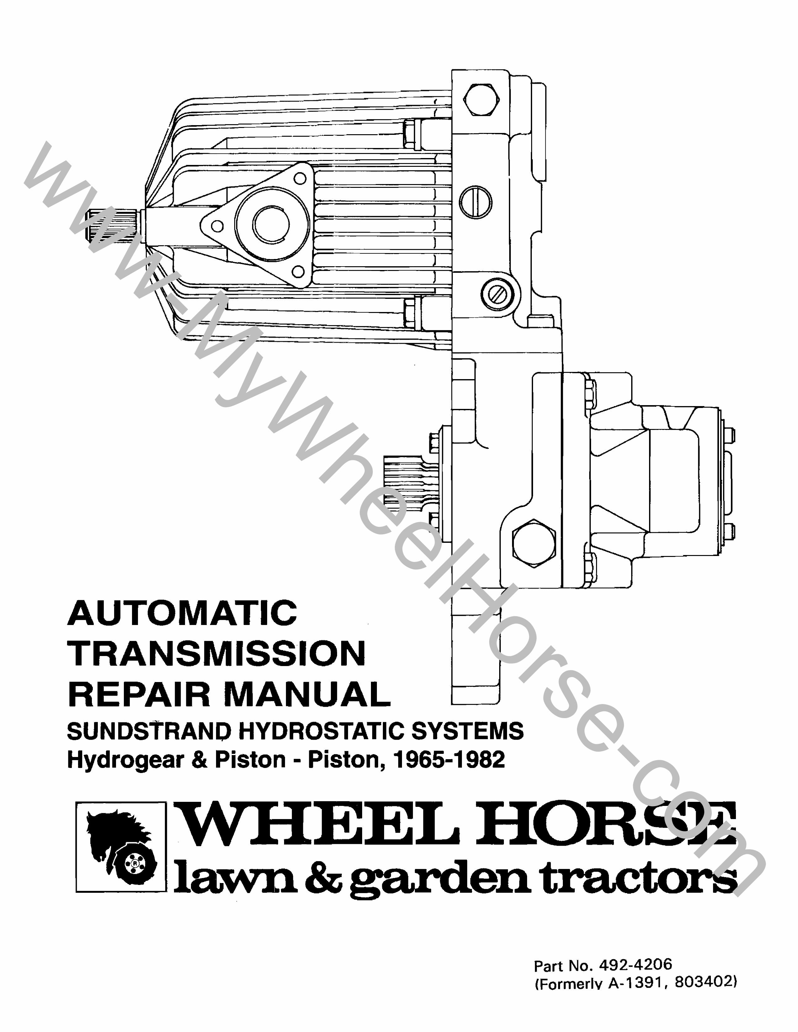
sundstrand hydrostatic systems hydrogear & piston
TRANSCRIPT
UT TR N REP IR
O~===!==I
o .
N NU L
SUNDSTRAND HYDROSTATIC SYSTEMS Hydrogear & Piston - Piston, 1965-1982
Part No. 492-4206 (Formerlv A-1391, 803402)
www-MyWheelHorse-com
..... z w ~ W ..J a.. a.. :::l en
..... z w ~ W ..J a.. a.. :::l en
..... z w ~ W ..J a.. a.. :::l en
SUPPLEMENTAL INFORMATION
INTRODUCTION
The following information will assist you with troubleshooting, assembly, and repair information, in light of changes made and experience gained since this manual was first published in 1974. It also contains special service information for 1978-82 model year Sundstrand units.
SERVICE AND REPAIR PARTS
• Hydrogear Conversions - Many hydrogear units (1966 to mid-1973) have been converted to the serviceable piston-piston transmission. Refer to the photos in this manual to identify the transmission in a particular tractor.
• Complete Transmissions - Complete replacement transmission assemblies are no longer available. Independent outside rebuilding service many be available. Refer to the latest issue of Service Bulletin 437 for information.
• Repair Parts - Use this manual to determine replacement part numbers for 1965 to mid-1973 hydrogear units (Pages 54-56) and mid-1973 to 1977 piston-piston units (Pages 60-62). Be sure to check parts price list to determine if all parts are still available before ordering parts.
Piston-piston part numbers for 1978-82 model year tractors are contained in the particular tractor parts manual.
• D-Series Adjustments - Transmission control linkage adjustments described in this manual for 1975 models are appropriate for 1976-77 models. 1978-82 linkage adjustments are covered in the 1978-79 B,C,D- Series Service Manual, PIN 810063R1.
• D-Series Driven Coupling Preload and Pump Alignment - Refer to Service Bulletins 217 and 305 for special service information .
CONSTRUCTION CHANGES, 1978 AND LATER
• Sundstrand units on 1978 and later tractors differ from earlier units in that the motor shaft extends through the cover plate, for the mounting of a parking brake drum. Motor repair operations described in this manual still apply, except that the motor cover plate oil seal should be replaced during the repair process.
Supplement 1
www-MyWheelHorse-com
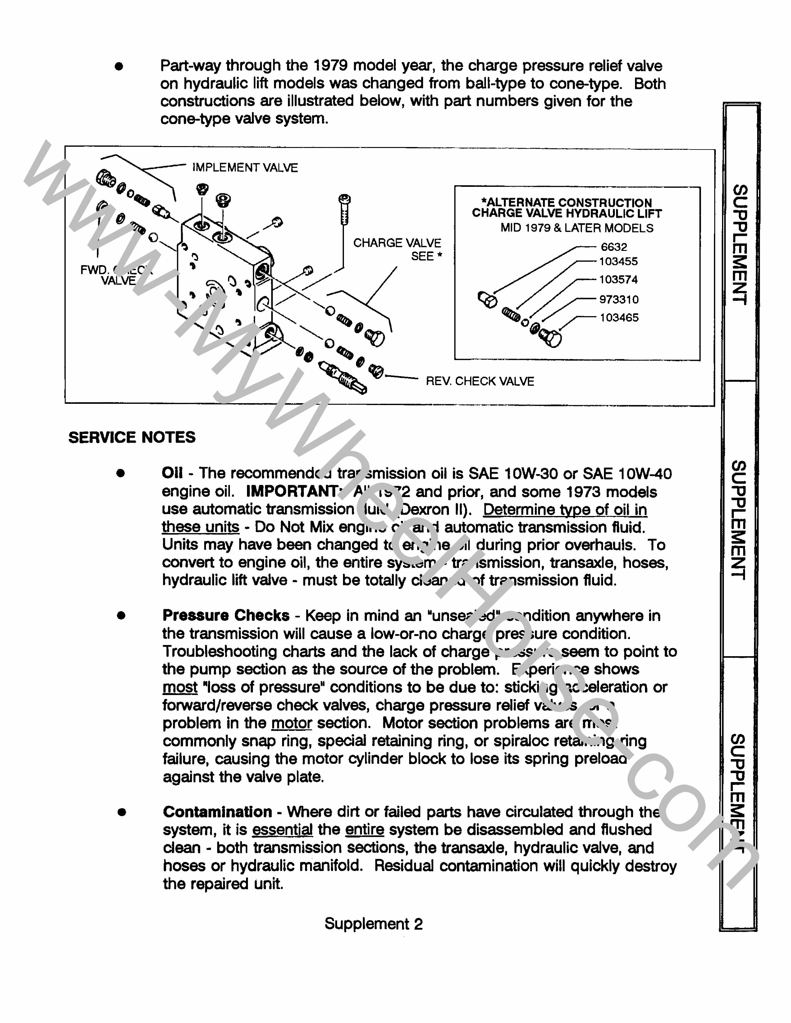
• Part-way through the 1979 model year, the charge pressure relief valve on hydraulic lift models was changed from ball-type to cone-type. Both constructions are illustrated below, with part numbers given for the cone-type valve system.
-.......--- IMPLEMENT VALVE
~(lo ~ ~~
t!) ~ """"""- ~::-....... *ALTERNATE CONSTRUCTION
CHARGE VALVE HYDRAULIC LIFT
{)
FWD. CHECK VALVE
CHARGE VALVE SEE *
'0
" .. " O~ ~
MID 1979 & LATER MODELS
-6632 .-r--1 03455
.,---103574
~,-,---------------------' '~- REV. CHECK VALVE
SERVICE NOTES
•
•
•
Oil - The recommended transmission oil is SAE 10W-30 or SAE 10W-40 engine oil. IMPORTANT: All 1972 and prior, and some 1973 models use automatic transmission fluid (Dexron II). Determine type of oil in
= - Do Not Mix engine oil and automatic transmission fluid. Units may have changed to engine oil during prior overhauls. To convert to engine oil, the entire system - transmission, transaxle, hoses, hydraulic lift valve - must be totally deaned of transmission fluid.
Pressure Checks - Keep in mind an uunsealedll condition anywhere in the transmission will cause a low-or-no charge pressure condition. Troubleshooting charts and the lack of charge pressure to point to the pump section as the source of the problem. Experience shows most ·'oss of conditions to be due to: sticking acceleration or forward/reverse check valves, charge pressure relief valves, or a problem in the motor section. Motor section problems are most commonly snap ring, special retaining ring, or spiraloc retaining ring failure, causing the motor cylinder block to lose its spring preload against the valve plate.
Contamination - Where dirt or failed parts have circulated through the system, it is essential the entire system be ed and flushed dean - both transmission sections, the transaxle, hydraulic valve, and hoses or hydraulic manifold. Residual contamination will quickly destroy the repaired unit.
Supplement 2
(J) C "0 "0 ,... m ;: m ~
(J) C "0 "0
Iii ;: m ~
(J) C "0 "0 ,... m ;: m ~
www-MyWheelHorse-com
..... z w ~ W -I a.. a.. :::> C/)
..... z w ~ W -I a.. a.. :::> C/)
..... z w ~ W -I a.. a.. :::> C/)
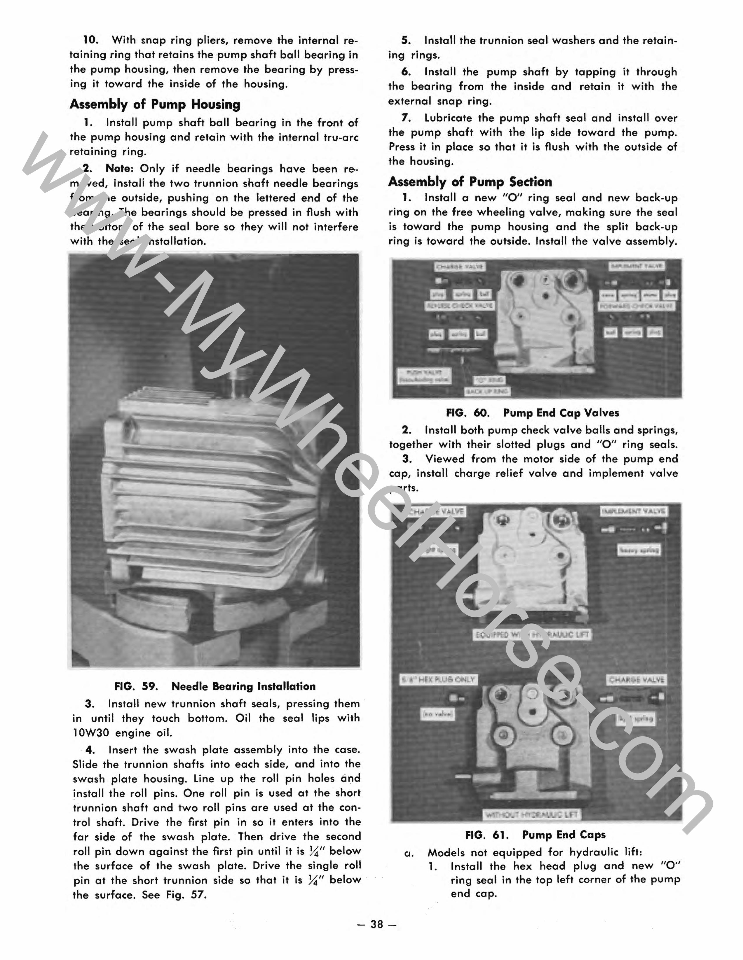
• Valve Plates - Note the difference between the pump and motor valve plates (Fig. 44). Ensure the correct valve plate is ordered when replacing, as the motor plate will fit in place of the pump plate, but will not function properly. Scratches in the brass surface of the plate that can be felt with a fingernail indicate an un~~rviceabl~ valve plate. The cylinder block may also be unserviceable in this case .
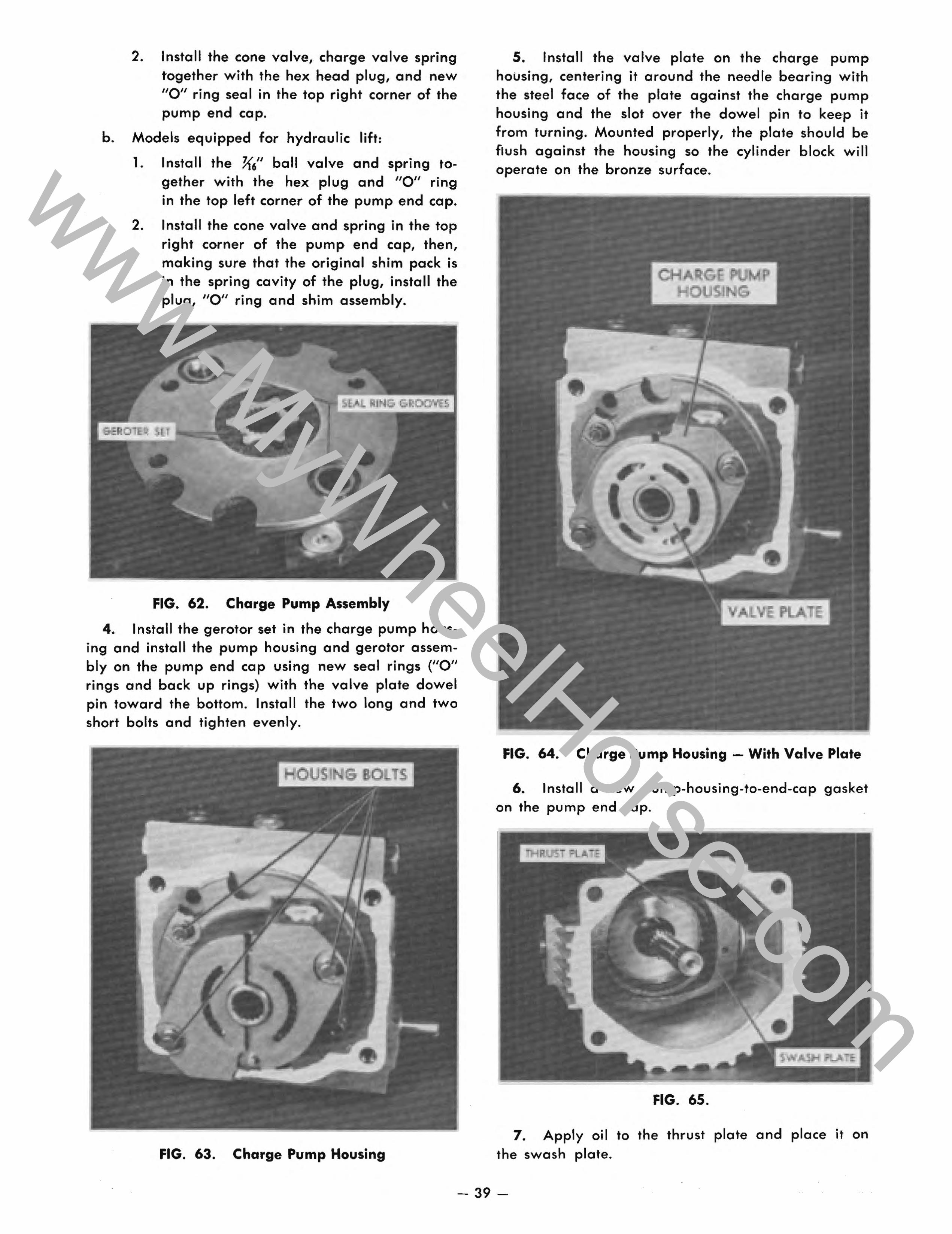
• Charge and Implement Valves - Note the location of these valves, depending on whether the tractor has manual or hydraulic lift (Fig. 61). Using the appropriate valve parts in the correct hole permits setting up any piston-piston unit for either type of lift system.
• Ch~rge Pump - Refer to the installation of the charge pump (Fig. 49). With the pump end cap positioned as shown, note that the dowel pin is down (nearest the sealing surface of the pump end cap). The charge pump can be put on upside-down, and will fail to function.
Also note that the charge pump n Ie bearing, Fig. 54, must protrude above the housing surface, to hold the valve plate in place. Use care to prevent accidentally pressing the dowel pin into the housing. Be sure the valve plate notch is over the dowel pin on assembly, or the valve plate will be ruined.
• Control Shaft/Stub Shaft - On 1978 and later transmissions, the longer control shaft is used on both sides of the pump housing (Fig. 57). Using a later transmission on an earlier tractor may require cutting a clearance hole in the tractor's sheet metal for the longer shaft.
• Acceleration Valves - Original equipment valves are different (Fig. 68) and must not be exchanged during repair. However, the forward valve is used as the service replacement part for both locations.
If an acceleration valve seems to be malfunctioning, ensure the metering plug hole is open (Fig. 70). If clogged, it will prevent the valve from closing. The hole is extremely ~rnall., and it may take a magnifying glass to see it.
• Motor Section - Note that the webbed section of motor housing must be "up" (Fig. 74), or motor will run opposite the intended direction.
Special Assembly Note
Ensure you use new retaining parts in the motor section (Items 23,70,73,74, Pages 61-62), to ensure the integrity of the cylinder block attachment to the motor shaft. On assembly, make ab$9.lutely'_~~m~ the cylinder block is locked securel~ on the motor shaft. Be sure the notch in the valve plate is over the dowel pin in the motor end cap.
Supplement 3
www-MyWheelHorse-com
This service and repair manual has been compiled to provide
authorized Wheel Horse service personnel with the proper procedures
and techniques for servicing Wheel Horse automatic transmissions.
The following index lists all areas covered. It is advisable to read
all of the introductory sections first to gain a proper understanding of
the Wheel Horse automatic transmission.
The automatic transmission is a sophisticated piece of machinery.
Maintain strict cleanliness control during all stages of service and
repair. Even a small amount of dirt or other contamination can severely
damage the system.
Although this manual deals primarily with the Sundstrand piston
piston type hydrostatic transmission, service and repair procedures for
the older hydrogear type transmission have been included in a separate
section.
L..-______________________ . __ .• _, ______________ .--J
-1-
www-MyWheelHorse-com
INDEX PAGE
PRINCIPLES OF TlON . .. .. .. .. .. .. .. .. .. .. . .. .. .. .. .. .. .. .. .. .. .. .. .. .. .. " .. .. 5
Relief Valves . . . . . . . . . . . . . . . . . . . . . . . . . . . . . . . . . . .. 5
Forwa rd Travel . . . . . . . . . . . . . . . . . . . . . . . . . . . . . . . . .. 5
Reverse Travel . . . . . . . . . . . . . . . . . . . . . . . . . . . . . . . . . .. 5
Acceleration Valves .............................. 5
Push Valve .............. ~ .......................... " ...................... ., .... 5
DIAGNOSIS ........................................... " .................................... "" 9
TROUBLE-SHOOTING CHARTS ............................ 9
SPEED CONTROL LINKAGE AND ADJUSTMENTS -
Standard System . . . . . . . . . . . . . . . . . . . . . . . . . . . . . . . .. 19
Neutral Adjustment .............................. 19
Friction Adj ustment . . . . . . . . . . . . . . . . . . . . . . . . . . . . . .. 19
SPEED CONTROL LINKAGE AND ADJUSTMENTS -
Sepa rated System . . . . . . . . . . . . . . . . . . . . . . . . . . . . . . .. 19
1973 18 HP Automatic
Neutral Adjustment ......................... 19
Friction Adjustment . . . . . . . . . . . . . . . . . . . . . . . . .. 20
Parking Brake Adjustment ... . . . . . . . . . . . . . . . .. 20
1974 liD" Series Tractors -
Neutral Adjustment ........................ ~. 22
lever Position Adjustment . . . . . . . . . . . . . . . . . . . .. 22
Speed Control Friction Adjustment . . . . . . . . . . . . .. 22
Parking Brake Friction Adjustment . . . . . . . . . . . . .. 23
Parking Brake Adjustment .................... 23
1975 "0" Series Tractors -
Neutral Adjustment ......................... 23
lever Friction Adjustment . . . . . . . . . . . . . . . . . . . .. 23
Parking Brake Adjustment .................... 23
PRESSURE TESTING •...................... . . . . . • . . . . . . .. 24
Charge Pressure Test ....................•........ 24
Implement Pressure Test . . . . . . . . . . . . . . . . . . . . . . . . . .. 25
-2-
www-MyWheelHorse-com
INDEX PAGE
REPAIR PROCEDURES ................................... 25
Separation of Pump and Motor ........... '.' . . . . . . .. 25
Seal Ring Installation ............................. 26
Assembly of Pump to Motor . . . . . . . . . . . . . . . . . . . . . . .. 26
REMOVAL OF HYDROSTATIC UNIT FROM A STANDARD SYSTEM . . . . . . . . . . . . . . . . . . . . . . . . . . . .. 26
INSTALLATION OF HYDROSTATIC UNIT IN A STANDARD SYSTEM . . . . . . . . . . . . . . . . . . . . . . . . . . . . . . .. 26
REMOVAL OF HYDROSTATIC UNIT FROM A SEPARATED SYSTEM . . . . . . . . . . . . . . . . . . . . . . . . . . . .. 27
Motor Remova I ........ .. .. ... .. .. .. .. .. .. .. .. .. .. .. ~ .. .. .. .. .. .. .. .. .. .. .. .. . .... 27
Pump Removal .................................................................. '" 27
INSTALLATION OF HYDROSTATIC UNIT IN A SEPARATED SYSTEM ............................... 27
Pump Installation ................................ 27
Manifold Installation ............................. 28
Motor I nsta lIation ................................ 30
INSPECTION OF PARTS . . . . . . . . . . . . . . . . . . . . . . . . . . . . . . . . .. 32
Pump and Motor Shafts .. . . . . . . . . . . . . . . . . . . . . . . . .. 32
Cylinder Block Assemblies ......................... 32
Cylinder Block Face .............................. 32
Pistons and Slippers .............................. 32
Slipper Retainers ................................ 33
Va Ive Plates ........................................................................ 33
Thrust Plates ............................................................. ,. .. " .... 33
Charge Pump Assembly .......•.................. 33
Bearings .......... ,. .................................... ,............................. 33
DISASSEMBLY AND ASSEMBLY OF HYDROSTATIC PUMP ....... 34
PUMP HOUSING DISASSEMBLY AND ASSEMBLY ....... . . . . . .. 37
Disassembly ........................................................................ 37
Assembly of Pump Housing ........................ 38
Assembly of Pump Section ......................... 38
-3-
www-MyWheelHorse-com
PAGE
REMOVAL AND REPLACEMENT OF ACCELERATION VALVES . .... 40
Disassem bly ..................................... 41
Assembly ... '. . . . . . . . . . . . . . .. . . . . . . . . . . . . . . . . . . .. 41
DISASSEMBLY AND ASSEMBLY OF HYDROSTATIC MOTOR .... .. 41
Disassembly of Motor . . . . . . . . . . . . . . . . . . . . . . . . . . . .. 41
Assem bly of Motor . . . . . . . . . . . . . . . . . . . . . . . . . . . . . .. 45
DISASSEMBLY AND ASSEMBLY OF CYLINDER BLOCKS AND PISTON ASSEMBLIES . . . . . . . . . . . . . . . . . . . . . . . . . . . . . . .. 46
HYDROGEAR SECTION .................................. 47
Hydrogear Trouble-Shooting Chart . . . . . . . . . . . . . . . . . .. 48
Trouble Shooting Guide ........................... 49
Preliminary Checks ............................... 49
Hydrogear Tune-up .... ' . . . . . . . . . . . . . . . . . . . . . . . . .. 49
Hydrogear Service Note ....... . . . . . . . . . . . . . . . . . . .. 50
Check Valves ......................... . -. . . . . . . . . .. 51
Charge Relief Valve .............................. 52
Towing Valve .................................... 52
Implement Relief Valve . . . . . . . . . . . . . . . . . . . . . . . . . . .. 52
Hydrogear Removal and Replacement . . . . . . . . . . . . . . .. 52
HYDROGEAR TRANSMISSION PARTS DRAWING .............. 54
HYDROGEAR PARTS LIST ................................ 55
HYDROGEAR PUMP SHAFT SEAL REPLACEMENT ............ " 56
THE TRANSAXLE .. . . . . . . . . . . . . . . . . . . . . . . . . . . . . . . . . . . . .. 57
Removal of Transaxle Complete with Hydrostatic Unit .... 57
Removal of Hydrostatic Unit from the Transaxle . . . . . . .. 57
Transaxle Disassembly ............................ 57
Parking Brake and Oil Filter . . . . . . . . . . . . . . . . . . . . . . .. 58
Transaxle Gasket Installation ........ . . . . . . . . . . . . . .. 59
PISTON-PISTON HYDROSTATIC PARTS DRAWING ............. 60
PISTON-PISTON HYDROSTATIC PARTS LIST .................. 61
-4-
www-MyWheelHorse-com
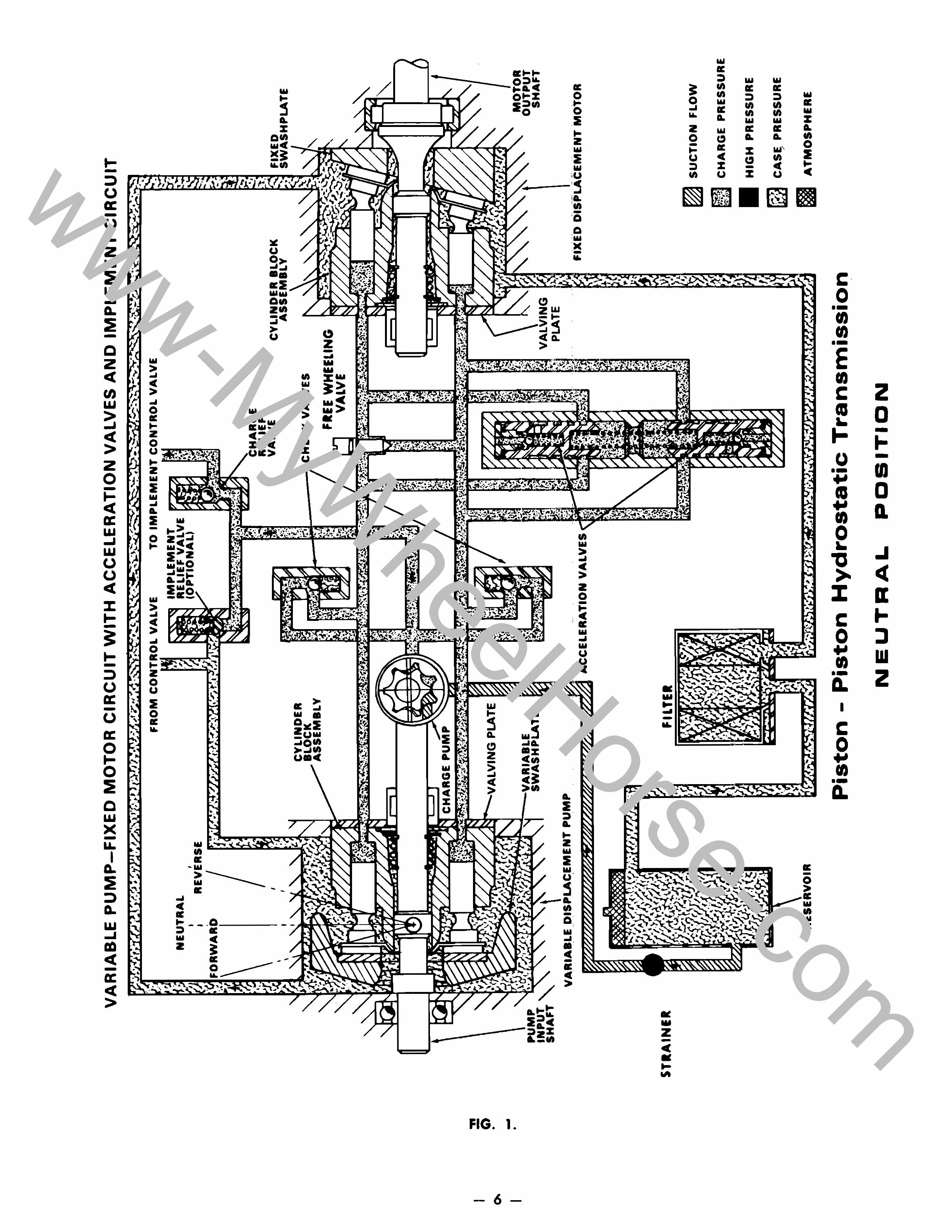
PRINCIPLES OF OPERATION
(Refer to the Neutral, Forward & Reverse Schematic Diagrams, Figs. 1 (Pg. 6), 2 (Pg. 7), 3 (Pg. 8).
Power is transmitted from the engine through a flexible coupling or belt and pulley arrangement to the pump shaft (shown at left of diagrams). Rotation of the input shaft causes the main pump cylinder block and the charge pump to turn, initiating the power transmitting function. Oil from the reservoir is drown by the charge pump through the inlet strainer and forced, by way of the check valves, into the low pressure lines. Oil introduced by the charge pump fills the area in back of the cylinder block pistons, holding them against their swash plates in both the pump and the motor.
When the pump swash plate is in neutral the pump cylinder block pistons do not move in and out. Thus, in neutral, no oil is being pumped from the variable displacement pump.
Low pressure oil from the charge pump fills the complete system, including the area around the acceleration valves. These valves are held open by the spring between them. The acceleration valves remain open until high pressure oil is introduced behind one of them. Which valve depends on the direction of rotation as determined by the position of the pump swash plate.
RELIEF VALVES
Pressure from 70 to 150 PSI is controlled by the charge pressure relief valve. This exhausts the excess charge oil not needed to make up leakage to the oil filter and case reservoir. When an implement is used, the maximum charge pressure, from 550 to 700 PSI, is limited by the implement relief valve.
Some separated systems also incorporate a high pressure relief valve which serves to prolong the life of the hydrostatic unit. Located on the left side of the tractor above the transmission, this relief valve has been factory adjusted and will reset automatically if triggered.
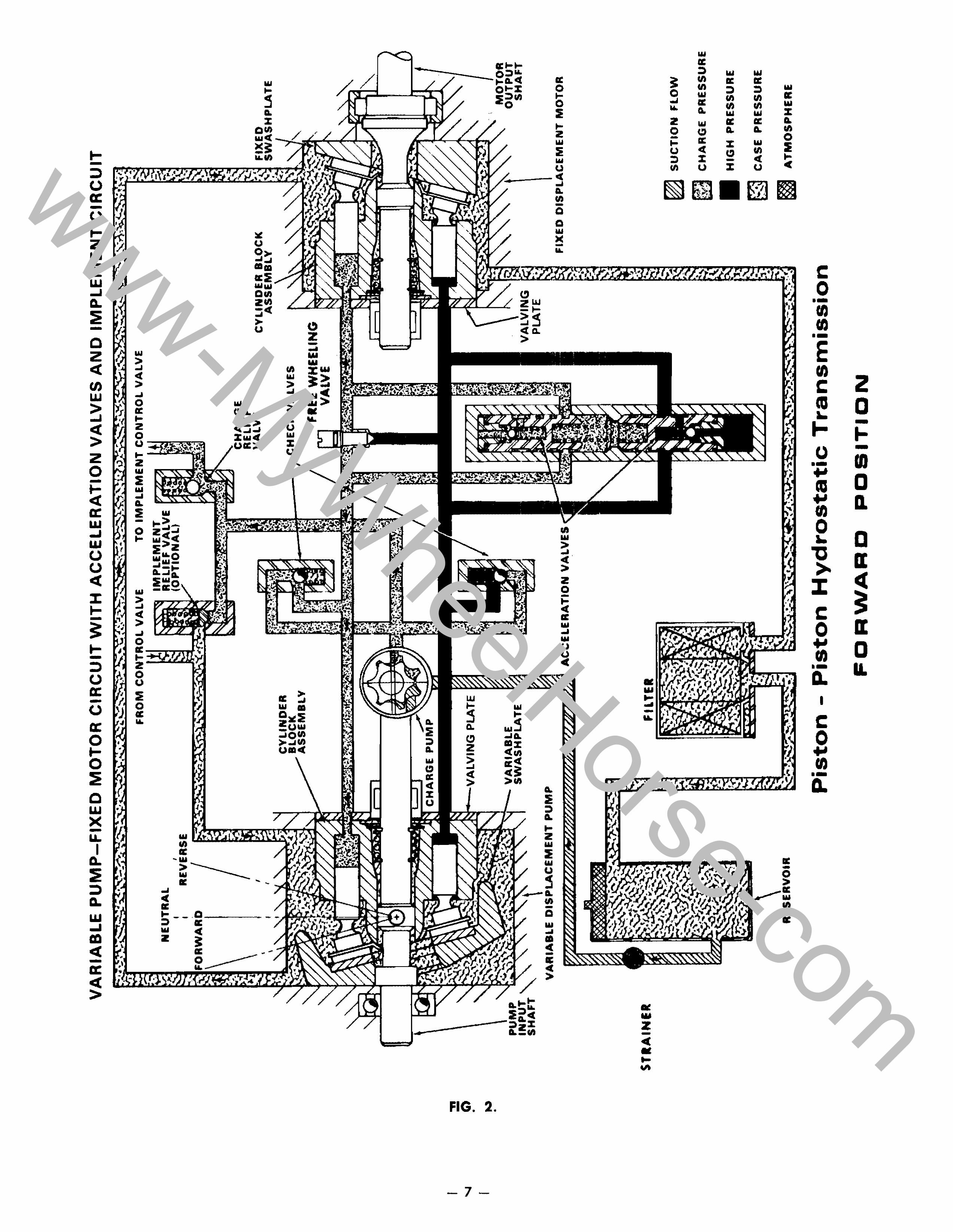
FORWARD TRAVEL
In forward position the pump variable swash plate tilts and, as the cylinder block continues to rotate, the pistons cross over a valving plate under low pressure
and advance up the swash plate. This in turn pushes them into the block, forcing the oil from the block under high pressure. At the bottom of their stroke,
the pistons pass again to the low pressure side of the valving plate and are refilled by the charge pump with oil returning from the motor through the low pressure line. The high pressure oil (shown in black) closes the high pressure check valve and travels through internal passages to the inlet side of the
piston motor.
In the motor, high pressure oil acting on the back
of the piston forces the piston down the incline causing the block to rotate and turn the output shaft.
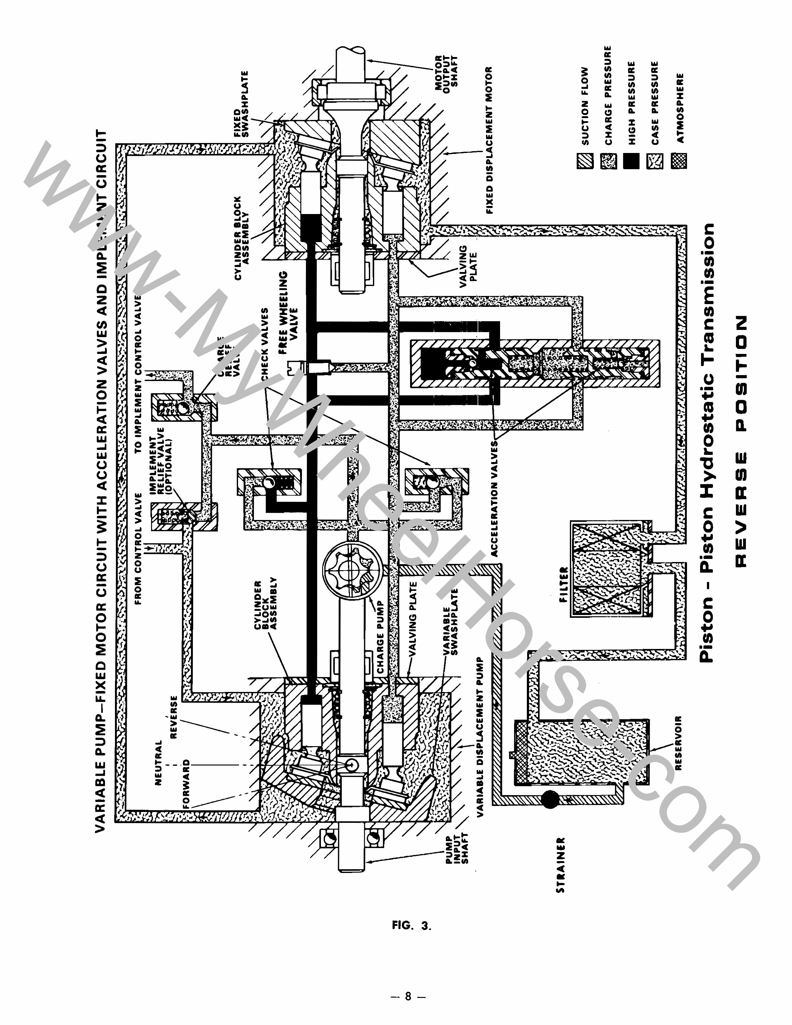
REVERSE TRAVEL When the control handle is moved to the reverse
position, the pump variable swash plate is tilted in the opposite position which changes the direction of oil flow. The high Clnd low pressure circuits interchange causing the motor to rotate in the opposite direction.
ACCELERATION VALVES The acceleration valves are placed in the circuit to
limit vehicle acceleration to a safe rate. With the control lever in neutral, oil is under low pressure throughout the circuit. When the control lev'er is advanced, the circuit pressure increases, causing the oil on the high pressure side to bleed by the flats on the valve lands and into the low pressure side. This high pressure oil continues to bleed to the low pressure side, by-passing the piston motor and holding the acceleration rate to a safe level during the time it takes for the acceleration valve to close against its seat. The delay in closing the valve is due to the time it takes the high pressure oil to bleed through the small orifice in the acceleration valve metering plug end into the
area behind the valve.
PUSH VALVE When open, the push or free wheeling valve allows
the oil to by-pass or flow from one side of the main circuit to the other. When pushing, the motor becomes a pump forcing the oil through the open valve and to the other side of the motor. The direction of oil flow depends on the direction the unit is pushed.
NOTE: On "8" and "c" series tractors, and similar prior models, the hydrostatic pump and motor are bolted together as a single unit. For purposes of description we will refer to such a transmission system as a "standard system".
On "0" series tractors, and similar prior models, the pump and motor are separated incorporating a manifold between them. In this manual We refer to such a system as a "separated system".
-5-
www-MyWheelHorse-com
I 0-
I
"ft -Q •
-•
VARIABLE PUMP-FIXED MOTOR CIRCUIT WITH ACCELERATION VALVES AND IMPLEMENT CIRCUIT
PUMP INPUT'\. SHAFT "'
NEUTRAL I ' I REVERSE
ro,I '''''!In'''!,
CHARGE
VARIABLE DISPLACEMENT PUMP
FROM
CYLINDER BLOCK ASSEMBLY
NG PLATE ~
L VALVE TO IMPLEMENT CONTROL VALVE
IMPLEMENT VALVE
NAL,
•••
RELIEF VALVE
~--77 CHECK VALVES
CYLINDER BLOCK ASSEMBLY
FREE WHEELING VALVE
PLATE
E:--l FIXED ,:i SWASH PLATE
.- ...... ". _.
MOTOR OUTPUT
SHAFT
ACCELERATION VALVES FIXED DISPLACEMENT MOTOR
STRAINER
RESERVOIR
Piston - Piston Hydrostatic Transmission
NEUTRAL POSITION
~ SUCTION FLOW
Ri_C;
r::;;] ~
CHARGE PRESSURE
HIGH PRESSURE
CAS~ PRESSURE
§I ATMOSPHERE
www-MyWheelHorse-com
I " -'I Ci) •
I ..., •
STRAINER
VARIABLE PUMP-FIXED MOTOR CIRCUIT WITH ACCELERATION VALVES AND IMPLEMENT CIRCUIT
NEUTRAL I I
I REVERSE RWARD I ~
,
FROM CONTROL VALVE
CYLINDER BLOCK ASSEMBLY
LVING PLATE
r \J • VARIABLE SWASHPLATE
TO IMPLEMENT CONTROL VALVE
CYLINDER BLOCK Y
I 7 CHECK VALVES
FREE WHEELING t"l1""1 VA LV E
NG PLATE
FIXED r .. "j SWASHPLATE
MOTOR OUTPUT
SHAFT
VARIABLE MENT PUMP
ACCELERATION VALVES
RESE R
Piston - Piston Hydrostatic Transmission
FORWARD POSITION
FIXED DISPLACEMENT MOTOR
~ SUCTION FLOW
~ CHARGE PRESSURE
HIGH PRESSURE
~~ CASE PRESSURE
~ ATMOSPHERE
www-MyWheelHorse-com
I .,. -CIO Q
• I Co)
•
VARIABLE PUMP-FIXED MOTOR CIRCUIT WITH ACCELERATION VALVES AND IMPLEMENT CIRCUIT
PUMP INPUT "SHAFT "-
NEUTRAL I ,
I REVERSE
I
I ,
I VARIABLE DISPLACEMENT PUMP
STRAINER
RESE R
FROM CONTROL VALVE
CYLINDER BLOCK ASSEMBLY
PLATE
ACCELERATION VAL
TO IMPLEMENT CONTROL VALVE
1---77 CHECK VALVES
CYLINDER BLOCK ASSEMBLY
FIn WHEELING r'\I""I VALVE
PLATE
p..:J FIXED I.~.l SWASH PLATE
MOTOR OUTPUT
SHAFT
FIXED DISPLACEMENT MOTOR
~ SUCTION FLOW
~ CHARGE PRESSURE
HIGH PRESSURE
~ CASE PRESSURE
m ATMOSPHERE
Piston - Piston Hydrostatic Transmission
REVERSE POSITION
www-MyWheelHorse-com
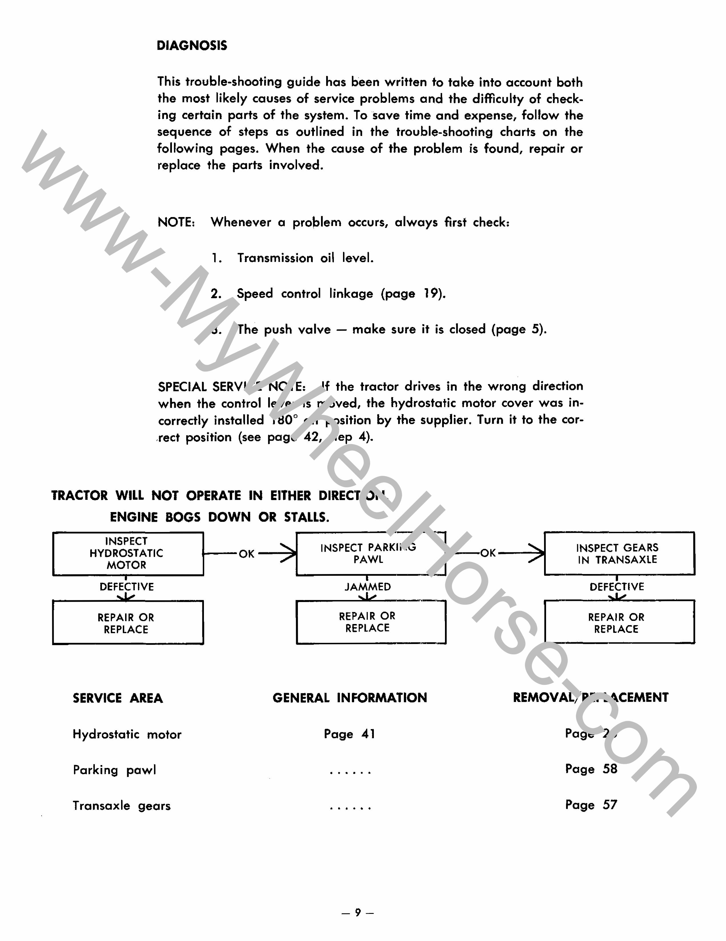
DIAGNOSIS
This trouble-shooting guide has been written to take into account both the most likely causes of service problems and the difficulty of checking certain parts of the system. To save time and expense, follow the sequence of steps as outlined in the trouble-shooting charts on the following pages. When the cause of the problem is found, repair or replace the parts involved.
NOTE: Whenever a pro~lem occurs, always first check:
1. Transmission oil level.
2. Speed control linkage (page 19).
3. The push valve - make sure it is closed (page 5).
SPECIAL SERVICE NOTE: If the tractor drives in the wrong direction when the control lever is moved, the hydrostatic motor cover was incorrectly installed 1800 off position by the supplier. Turn it to the cor,rect position (see page 42, step 4).
TRACTOR WILL NOT OPERATE IN EITHER DIRECTION.
ENGINE BOGS DOWN OR STALLS.
INSPECT HYDROSTATIC
MOTOR i--OK-""""; INSPECT PARKING
PAWL INSPECT GEARS IN TRANSAXLE
~-------.....I DEFECTIVE
REPAIR OR REPLACE
SERVICE AREA
Hydrostatic motor
Parking pawl
Transaxle gears
JAMMED
REPAIR OR REPLACE
GENERAL INFORMATION
Page 41
• • • • • •
• • • • • •
-9-
REPAIR OR REPLACE
REMOVAL/REPLACEMENT
Page 25
Page 58
Page 57
www-MyWheelHorse-com
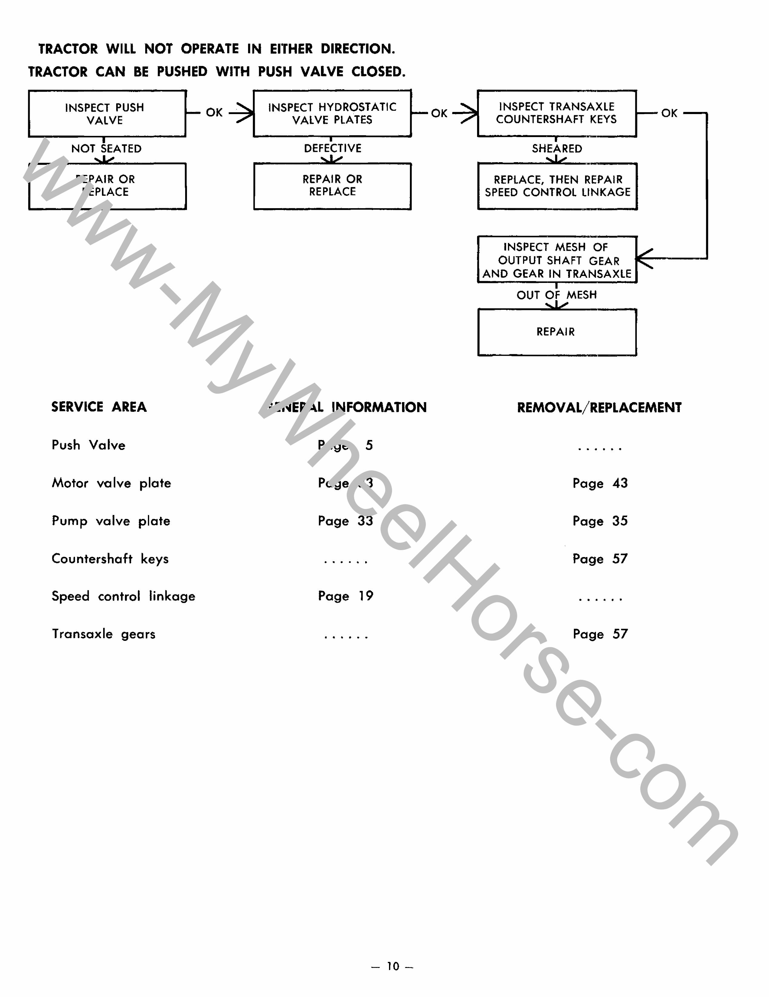
TRACTOR WILL NOT OPERATE IN EITHER DIRECTION.
TRACTOR CAN BE PUSHED WITH PUSH VALVE CLOSED.
INSPECT PUSH VALVE
NOT SEATED
REPAIR OR REPLACE
SERVICE AREA
Push Valve
Motor va Ive plate
Pump valve plate
Countershaft keys
-OK~
Speed control linkage
T ransaxle gears
INSPECT HYDROSTATIC VALVE PLATES
DEFECTIVE
REPAIR OR REPLACE
t--OK --'
GENERAL INFORMATION
Page 5
Page 33
Page 33
.. .. . .. . "
Page 19
" . " " .. ..
- 10-
INSPECT TRANSAXLE COUNTERSHAFT KEYS
SHEARED
REPLACE, THEN REPAIR SPEED CONTROL LINKAGE
INSPECT MESH OF OUTPUT SHAFT GEAR
AND GEAR IN TRANSAXLE
OUT OF MESH
REPAIR
-OK-
REMOVAL/REPLACEMENT
.. .. .. .. .. ..
Page 43
Page 35
Page 57
.. ... .. " " ..
Page 57
www-MyWheelHorse-com
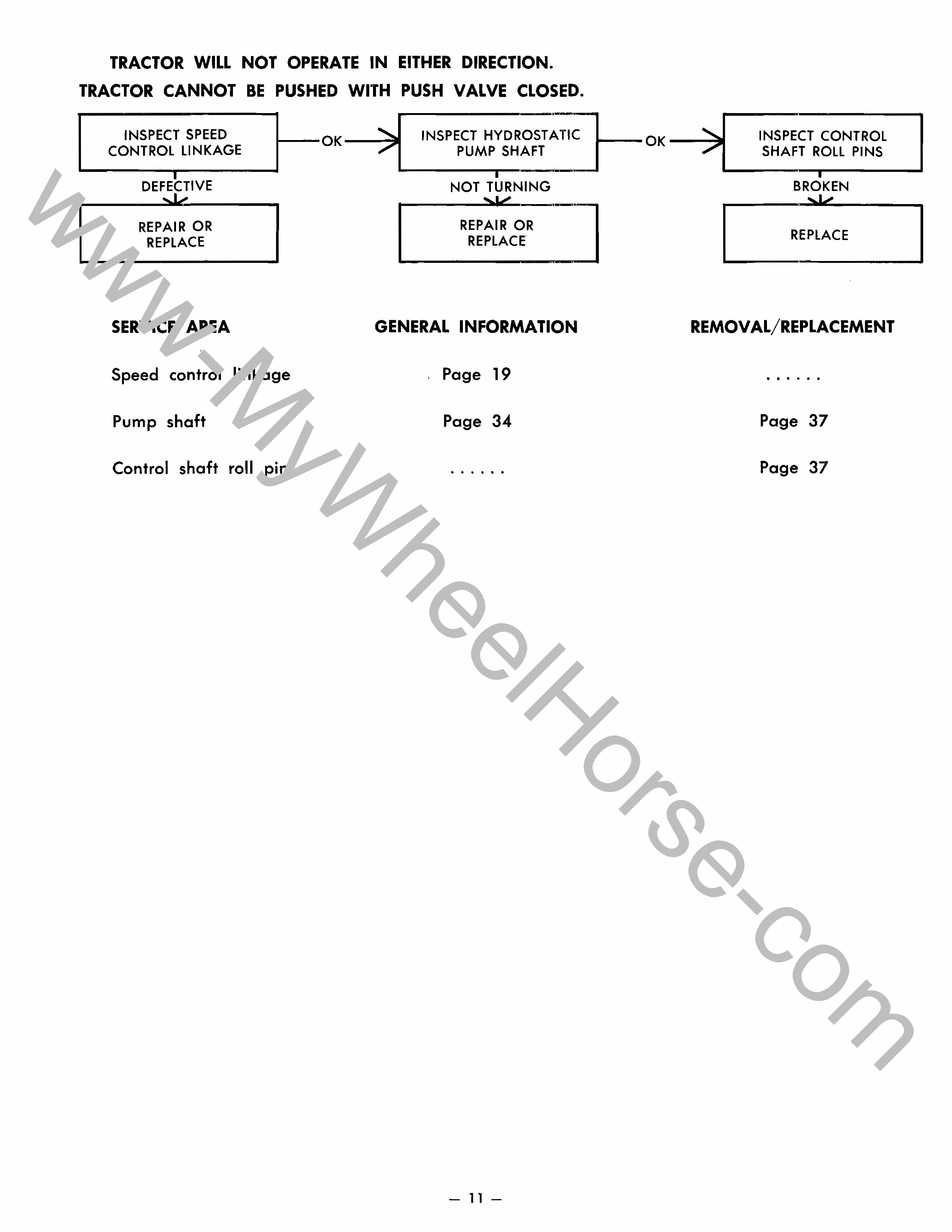
TRACTOR WILL NOT OPERATE IN EITHER DIRECTION.
TRACTOR CANNOT BE PUSHED WITH PUSH VALVE CLOSED.
INSPECT SPEED CONTROL LINKAGE
--OK----: INSPECT HYDROSTATIC PUMP SHAFT
I
DEFECTIVE
REPAIR OR REPLACE
SERVICE AREA
Speed control linkage
Pump shaft
Control shaft roll pins
NOT TURNING
REPAIR OR REPLACE
GENERAL INFORMATION
Page 19
Page 34
• • • • • •
-11-
--OK----: INSPECT CONTROl SHAFT ROlL PINS
BROKEN
REPLACE
REMOVAL/REPLACEMENT
• • • • • •
Page 37
Page 37
www-MyWheelHorse-com
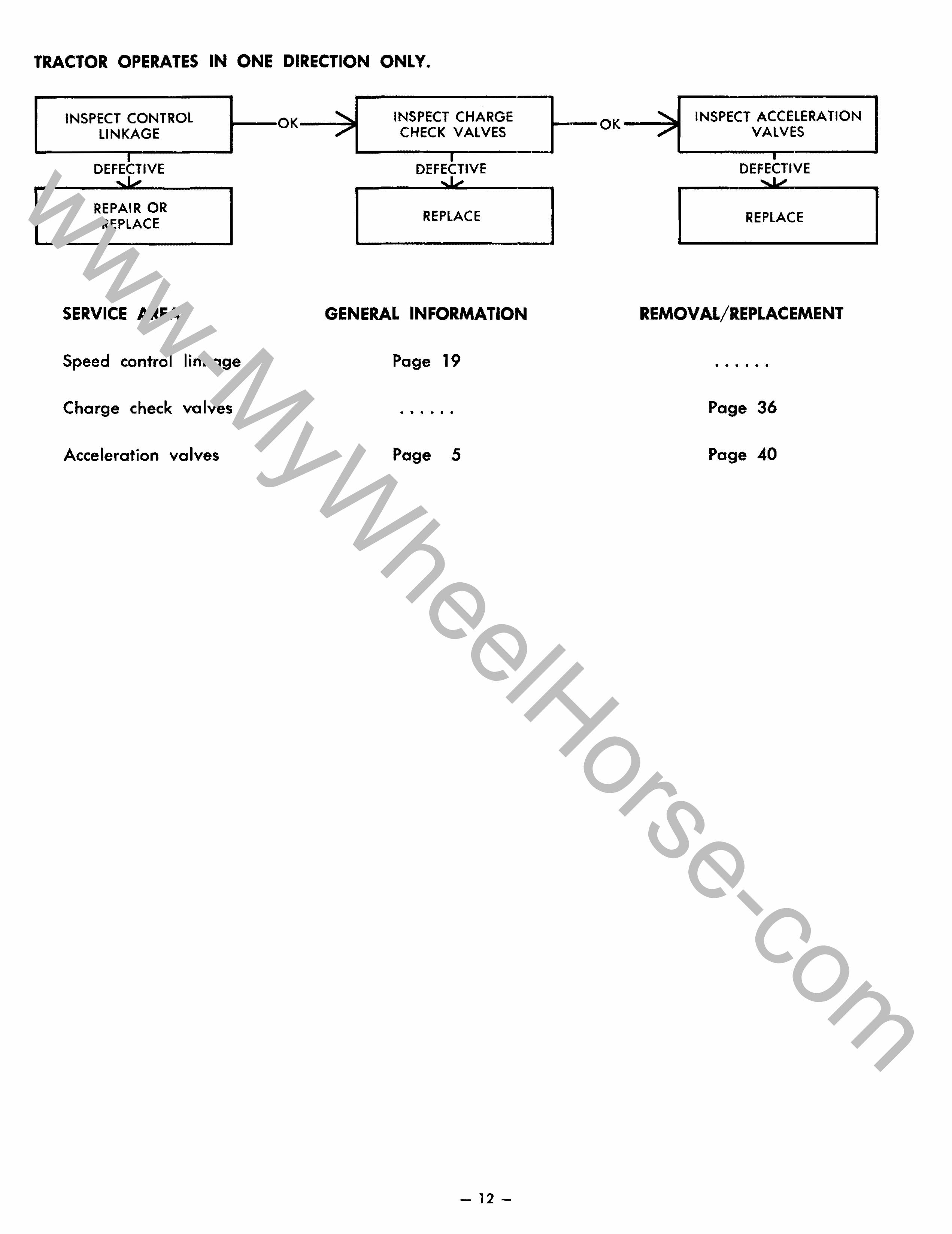
TRACTOR OPERATES IN ONE DIRECTION ONLY.
INSPECT CONTROL LINKAGE
--OK---..: INSPECT CHARGE CHECK VALVES
DEFECTIVE
REPAIR OR REPLACE
SERVICE AREA
Speed control linkage
Charge check valves
Acceleration valves
DEFE VE
REPLACE
GENERAL INFORMATION
Page 19
.. .. .. .. . ..
Page 5
- 12-
INSPECT ACCELERATION VALVES
DEFECTIVE
REPLACE
REMOVAL/REPLACEMENT
.. .. .. .. .. .
Page 36
Page 40
www-MyWheelHorse-com
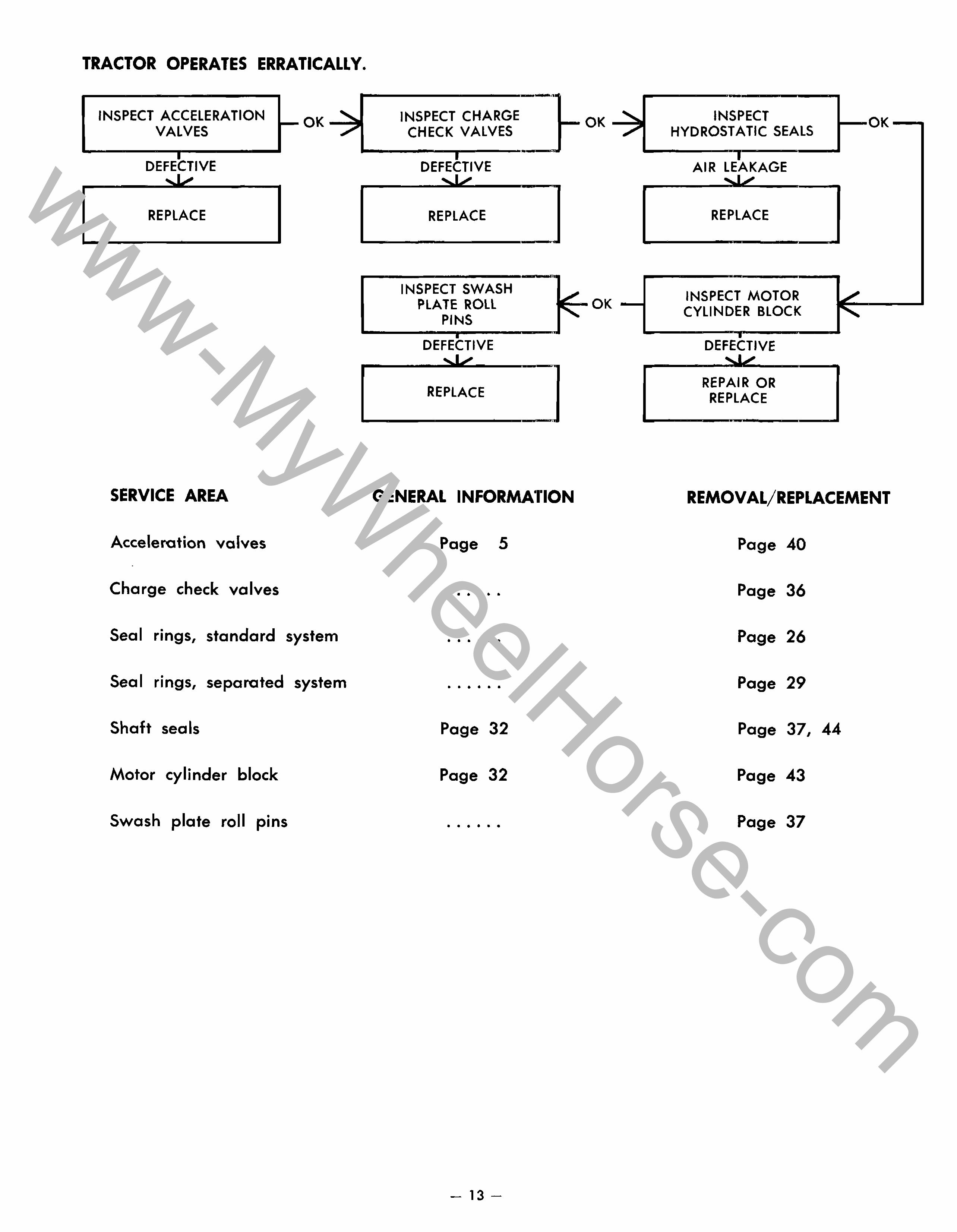
TRACTOR OPERATES ERRATICALLY.
INSPECT ACCElERATION VALVES
• DEFECTIVE
REPLACE
SERVICE AREA
Accelerotion valves
Charge check valves
- OK--.,;:
Seal rings, standard system
Seal rings, separoted system
Shaft seals
Motor cylinder block
Swash plate roll pins
INSPECT CHARGE CHECK VALVES
:FE(:TIVE
REPLACE
INSPECT SWASH PLATE ROLL
PINS ---D-EF- :;:~V;;E---
REPLACE
-OK~
~OK-
GENERAL INFORMATION
Page 5
• • • • • •
• • • • • •
• • • • • •
Page 32
Page 32
• • • • • •
- 13-
INSPECT HYDROSTATIC SEALS
AIR ..... ,
REPLACE
INSPECT MOTOR CYLINDER BLOCK
DEFECTIVE
REPAIR OR REPLACE
-OK--,
REMOVAL/REPLACEMENT
Page 40
Page 36
Page 26
Page 29
Page 37, 44
Page 43
Page 37
www-MyWheelHorse-com
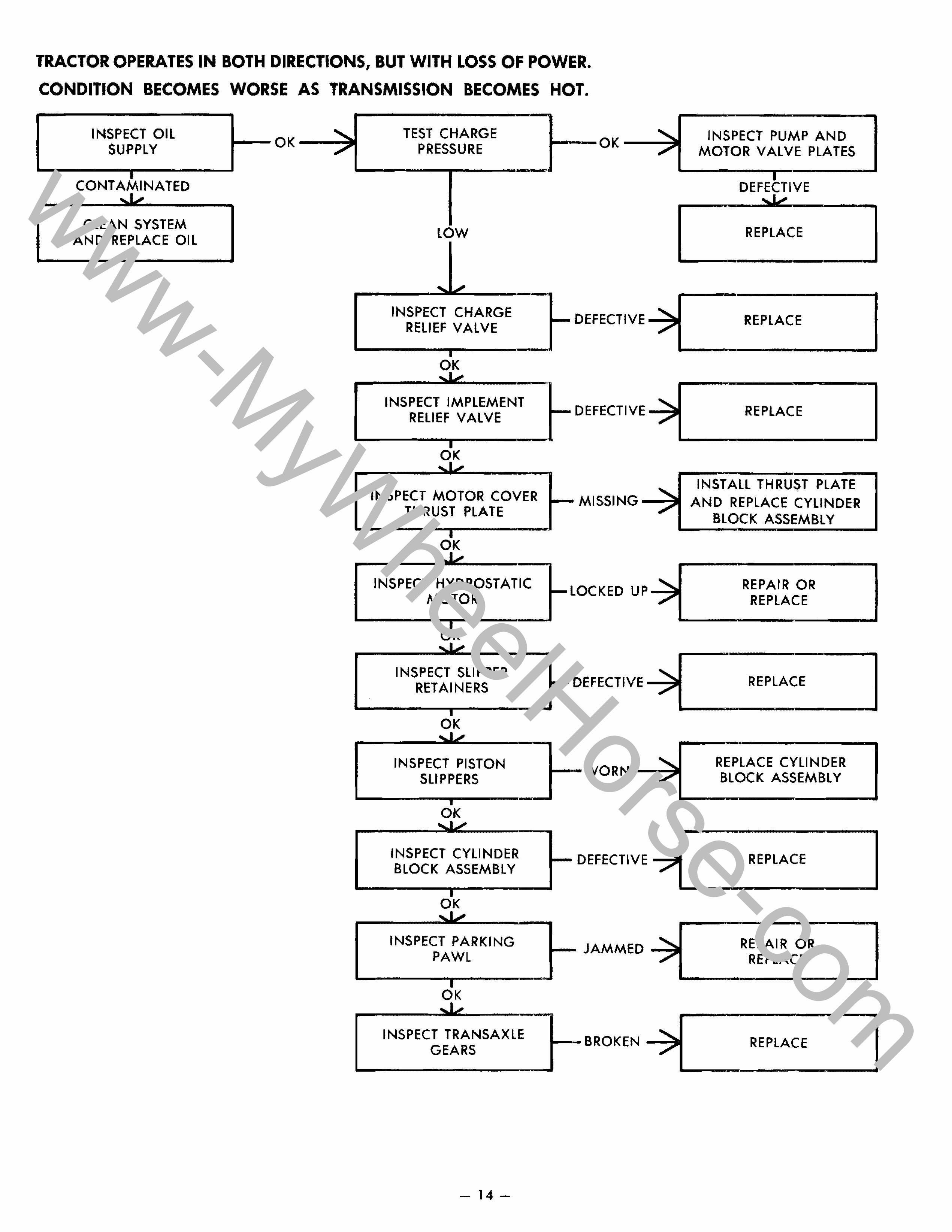
TRACTOR OPERATES IN BOTH DIRECTIONS, BUT WITH LOSS OF POWER.
CONDITION BECOMES WORSE AS TRANSMISSION BECOMES HOT.
INSPECT OIL SUPPLY
I CONT AMI NATED
CLEAN SYSTEM AND REPLACE OIL
--OK-~ TEST CHARGE
PRESSURE
INSPECT CHARGE RELIEF VALVE
OK
INSPECT IMPLEMENT RELIEF VALVE
INSPECT MOTOR COVER THRUST PLATE
OK
INSPECT HYDROSTATIC MOTOR
OK
INSPECT SLIPPER RETAINERS
OK
INSPECT PISTON SLIPPERS
OK
INSPECT CYLINDER BLOCK ASSEMBLY
OK
INSPECT PARKING PAWL
OK
INSPECT TRANSAXLE GEARS
-14-
--OK----:
- DEFECTIVE ~
- DEFECTIVE---::
- MISSING----::
-LOCKED UP-
- DEFECTIVE ~
-WORN -"""'i
- DEFECTIVE -.
- JAMMED.-.
~-BROKEN --:
INSPECT PUMP AND MOTOR VALVE PLATES
VE
REPLACE
REPLACE
REPLACE
INSTALL THRUST PLATE AND REPLACE CYLINDER
BLOCK ASSEMBLY
REPAIR OR REPLACE
REPLACE
REPLACE CYLINDER BLOCK ASSEMBLY
REPLACE
REPAIR OR REPLACE
REPLACE
www-MyWheelHorse-com
.
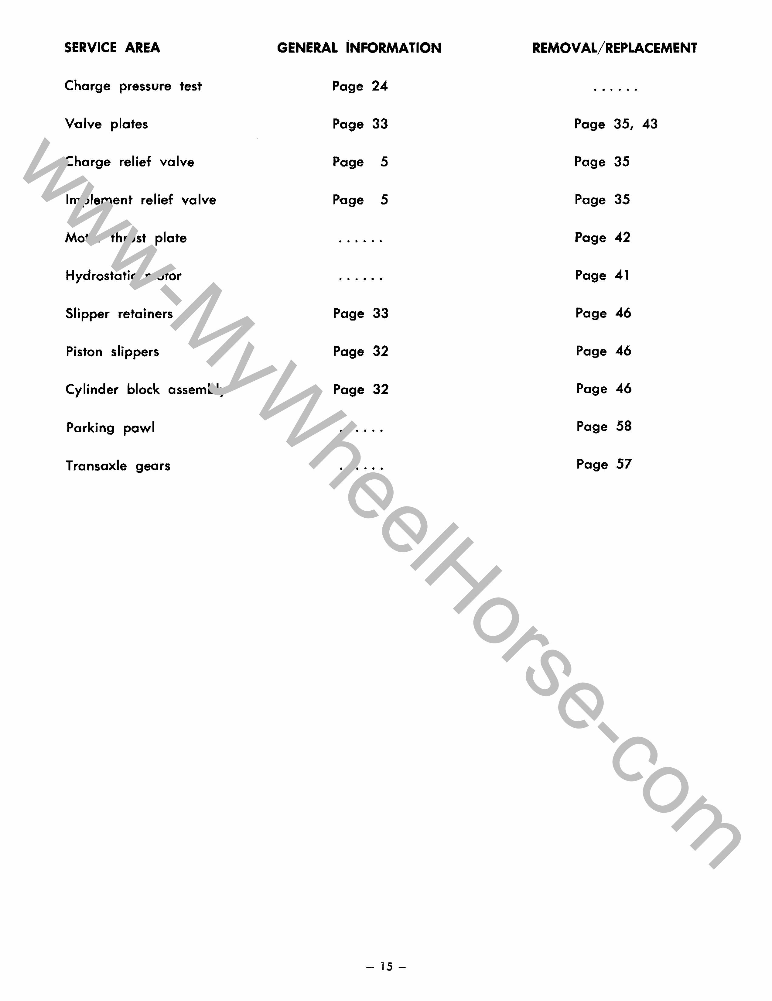
SERVICE AREA GENERAL INFORMATION REMOVAL/REPLACEMENT
Charge pressure test Page 24 " to .. .. .. ..
Va Ive plates Page 33 Page 35, 43
Charge relief valve Page 5 Page 35
Implement relief valve Page 5 Page 35
AAotor thrust plate .. .. .. .. .. .. Page 42
Hydrostatic motor .. . . .. .. .. Page 41
Slipper retainers Page 33 Page 46
Piston slippers Page 32 Page 46
Cylinder block assembly Page 32 Page 46
Parking pawl . .. . .. .. .. Page 58
Transaxle gears . .. .. .. . .. Page 57
- 15-
www-MyWheelHorse-com
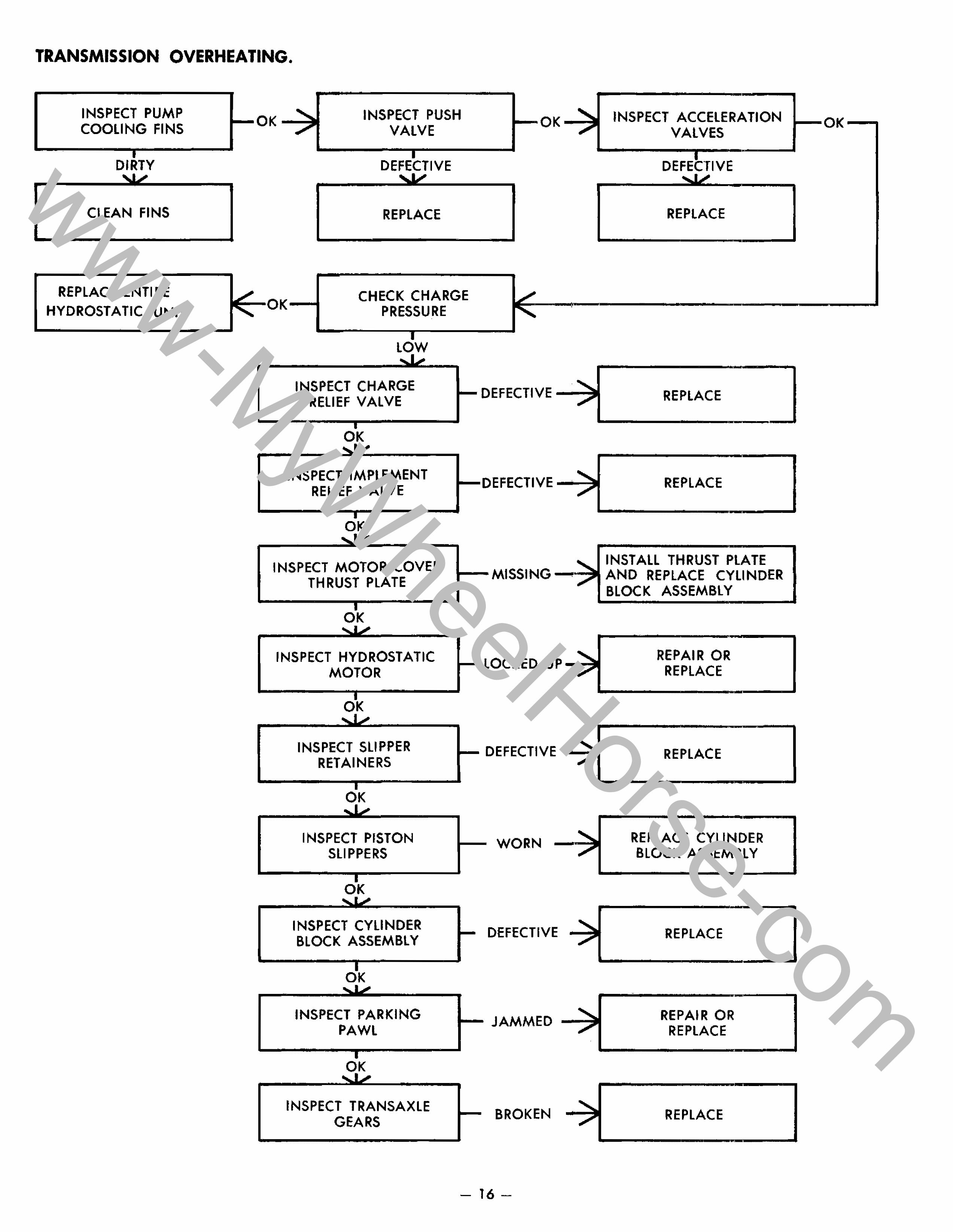
TRANSMISSION OVERHEATING.
INSPECT PUMP COOLING FINS
DIRTY
CLEAN FINS
REPLACE ENTIRE HYDROSTATIC UNIT
-OK --.,;: INSPECT PUSH VALVE
-OK---:;
D VE
REPLACE
CHECK CHARGE PRESSURE
LOW
INSPECT CHARGE RELIEF VALVE
OK
INSPECT IMPLEMENT RELIEF VALVE
INSPECT MOTOR COVER THRUST PLATE
INSPECT HYDROSTATIC MOTOR
OK
INSPECT SLIPPER RETAINERS
OK
I NSPECT PISTON SLIPPERS
INSPECT CYLINDER BLOCK ASSEMBLY
INSPECT PARKING PAWL
INSPECT TRANSAXLE GEARS
I- DEFECTIVE -.....;
-DEFECTIVE -..-;
- MISSING--=
~LOCKED UP~
I- DEFECTIVE ~
- WORN
DEFECTIVE
- JAMMED -.....;
BROKEN
- 16-
INSPECT ACCELERATION VALVES
REPLACE
REPLACE
REPLACE
INSTALL THRUST PLATE AND REPLACE CYLINDER BLOCK ASSEMBLY
REPAIR OR REPLACE
REPLACE
REPLACE CYLINDER BLOCK ASSEMBLY
REPLACE
REPAIR OR REPLACE
REPLACE
-OK-
www-MyWheelHorse-com
SERVICE AREA
Pump cooling fins
Push valve
Accelerotion valves
Charge pressure test
Entire hydrostatic standard system
• Unit,
.
Entire hydrostatic • Unit,
separated system
Charge relief valve
Implement relief valve
Motor thrust plate
Hydrostatic motor
Slipper retainers
Piston slippers
Cylinder block assembly
Parking pawl
Transaxle gears
GENERAL INFORMATION REMOVAL/REPLACEMENT
Page 34 • • • • • •
Page 5 • • • • • •
Page 5 Page 40
Page 24 • • • • • •
• • • • • • Page 26
• • • • • • Page 27
Page 5 Page 35
Page 5 Page 35
• • • • • • Page 42
• • • • • • Page 41
Page 33 Page 46
Page 32 Page 46
Page 32 Page 46
• • 10 • • • Page 58
• • • • • • Page 57
- 17-
www-MyWheelHorse-com
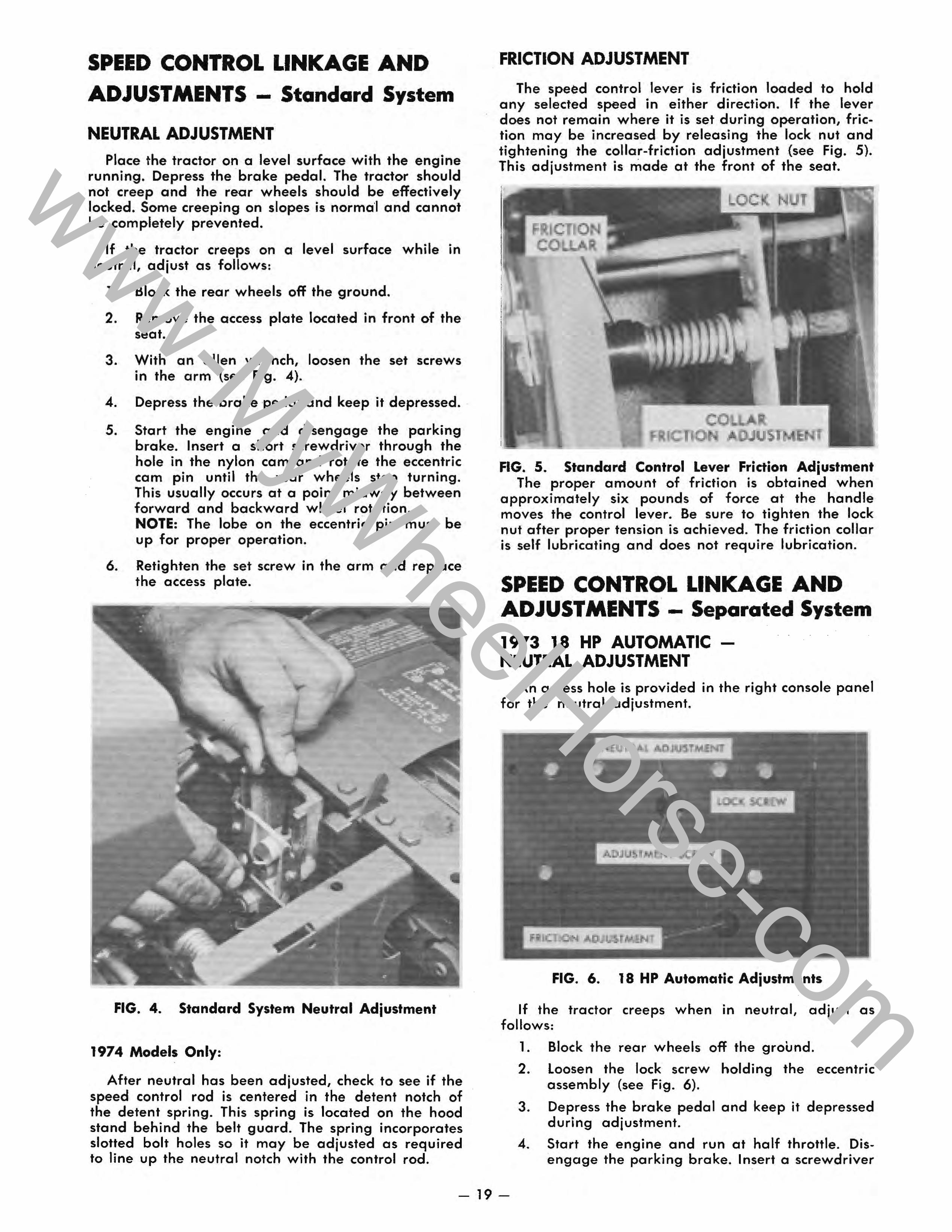
SPEED CONTROL LINKAGE AND
ADJUSTMENTS - Standard System
NEUTRAL ADJUSTMENT Place the tractor on a level surface with the engine
running. Depress the brake pedal. The tractor should not creep and the rear wheels should be effectively locked. Some creeping on slopes is norma'i and cannot be completely prevented.
If the tractor creeps on a level surface while in neutral, adjust as follows:
1. Block the rear wheels off the ground.
2. Remove the access plate located in front of the seat.
3. With an allen wrench, loosen the set screws in the arm (see Fig. 4).
4. Depress the brake pedal and keep it depressed.
5. Start the engine and disengage the parking brake. Insert a short screwdriver through the hole in the nylon cam and rotate the eccentric cam pin until the rear wheels stop turning. This usually occurs at a point midway between forward and backward wheel rotation. NOTE: The lobe on the eccentric pin must be up for proper operation.
6. Retighten the set screw in the arm and replace the access plate.
FIG. 4. Standard System Neutral Adjustment
1974 Models Only:
After neutral has been adjusted, check to see if the speed control rod is centered in the detent notch of the detent spring. This spring is located on the hood stand behind the belt guard. The spring incorporates slotted bolt holes so it may be adjusted as required to line up the neutral notch with the control rod.
FRICTION
The speed control lever is friction loaded to hold any selected speed in either direction. If the lever does not remain where it is set during operation, friction may be increased by releasing the lock nut and tightening the collar-friction adjustment (see Fig. 5). This adjustment is made at the front of the seat.
LOCK N T
co os
FIG. 5. Standard Control Lever Friction Adjustment The proper amount of friction is obtained when
approximcHely six pounds of force at the handle moves the control lever. Be sure to tighten the lock nut after proper tension is achieved. The friction collar is self lubricating and does not require lubrication.
SPEED CONTROL LINKAGE AND ADJUSTMENTS - Separated System
1973 18 HP AUTOMATIC -NEUTRAL ADJUSTMENT
An access hole is provided in the right console panel for the neutral adjustment.
FIG. 6. 18 HP Automatic Adjustments
If the tractor creeps when in neutral, adjust as follows:
1. Block the rear wheels off the ground.
2. loosen the lock screw holding the eccentric assembly (see Fig. 6).
3. Depress the brake pedal and keep it depressed during adjustment.
4. Start the engine and run at half throttle. Disengage the parking brake. Insert a screwdriver
- 19-
www-MyWheelHorse-com
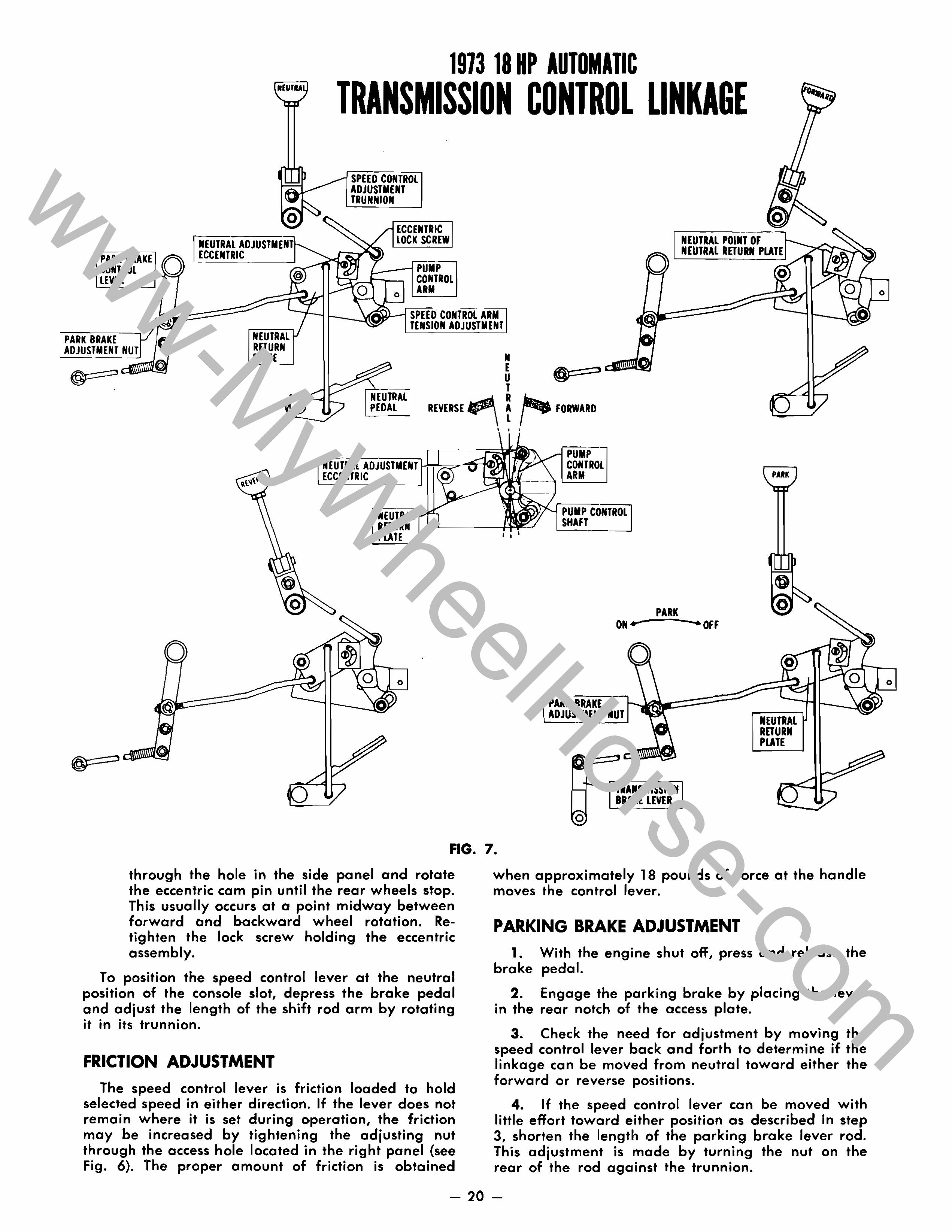
1913 18
PARK CONTROL LEVER
NEUTRAL ADJU ECCENTRIC
ADJUSTMENT TRUNNION
o
CONTROL ARM
NEUTRAL POINT OF NEUTRAL RETURN PLATE
SPEED CONTROL ARM TENSION ADJUSTMENT
PARK BRAKE ADJUSTMENT
N PEDAL
NEUTRAL AOJUSTMENT ECCENTRIC
o o
REVERSE
N E U T R A L
FORWARD
PUMP CONTROL ARM
PUMP SHAFT
PARK
ADJUSTMEIIIT IIIUT
TRANSMISSION BRAKE LMR
PARK
IIIEUTRAL RETURIII PLATE
o
FIG. 7.
through the hole in the side panel and rotate the eccentric cam pin until the rear wheels stop. This usually occurs at a point midway between forward and oockward wheel rotation. Retighten the lock screw holding the eccentric assembly.
To position the speed control lever at the neutral position of the console slot, depress the brake pedal and adjust the length of the shift rod arm by rotating • •• • It In Its trunnion.
FRICTION ADJUSTMENT The speed control lever is friction loaded to hold
selected speed in either direction. If the lever does not remain where it is set during operation, the friction may be increased by tightening the adjusting nut through the access hole located in the right panel (see Fig. 6). The proper amount of friction is obtained
when approximately 18 pounds of force at the handle moves the control lever.
PARKING BRAKE 1. With the engine shut off, press and release the
brake pedal.
2. Engage the parking brake by placing the lever in the rear notch of the access plate.
3. Check the need for adjustment by moving the speed control lever back and forth to determine if the linkage can be moved from neutral toward either the forward or reverse positions.
4. If the speed control lever can be moved with little effort toward either position as described in step 3, shorten the length of the parking brake lever rod. This adjustment is made by turning the nut on the rear of the rod against the trunnion.
- 20-
o
o
www-MyWheelHorse-com
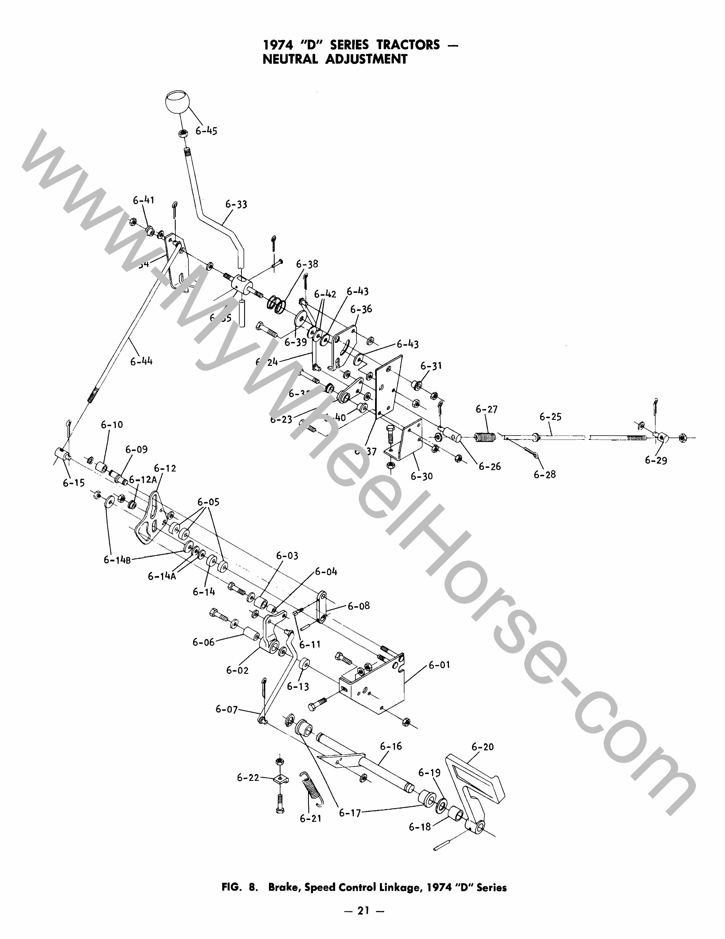
6-41
6-44
6-10
6-12
6-1
6-45
6-33
6-
----". 6-06
6- 2
6 07-___
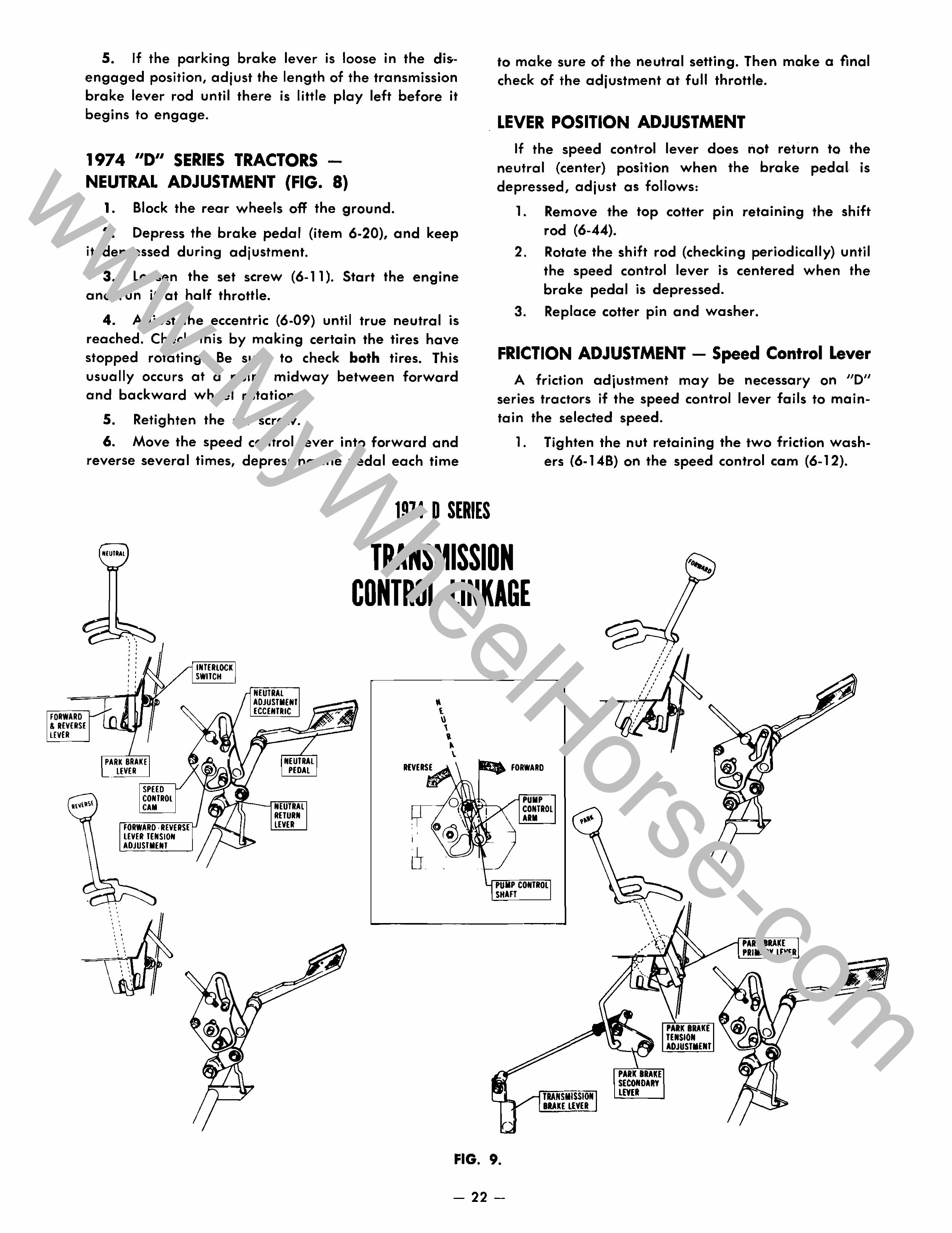
1974 liD" SERIES TRACTORS -NEUTRAL ADJUSTMENT
6-42 3 6-36
6-32-
6-23
6-37
1--6-08
6-01
6-22---., 6- 9
6-21
6-27
FIG. 8. Brake, Speed Control Linkage, 1974 "D" Series
- 21 -
'==
6-28
www-MyWheelHorse-com
5. If the parking brake lever is loose in the dis-engaged position, adjust the length of the transmission brake lever rod until there is little play left before it begins to engage.
1974 "D" SERIES TRACTORS -NEUTRAL ADJUSTMENT (FIG. 8)
1. Block the rear wheels off the ground.
2. Depress the brake pedal (item 6-20), and keep it depressed during adjustment.
3. loosen the set screw (6-11). Start the engine and run it at half throttle.
4. Adjust the eccentric (6-09) until true neutral is reached. Check this by making certain the tires have stopped rotating. Be sure to check both tires. This usually occurs at a point midway between forward and backward wheel rotation.
5. Retighten the set screw.
6. Move the speed control lever into forward and reverse several times, depressing the pedal each time
1914 0
N[Ulhl TRANS
to make sure of the neutral setting. Then make a final check of the adjustment at full throttle.
POSITION ADJUSTMENT If the speed control lever does not return to the
neutral (center) position when the brake pedal is depressed, adjust as follows:
1. Remove the top cotter pin retaining the shift rod (6-44).
2. Rotate the shift rod (checking periodically) until the speed control lever is centered when the brake pedal is depressed.
3. Replace cotter pin and washer.
FRICTION ADJUSTMENT - Speed Control Lever A friction adjustment may be necessary on "0"
series tractors if the speed control lever fails to maintain the selected speed.
1. Tighten the nut retaining the two friction washers (6- 14B) on the speed control cam (6-12).
CONTROL LINKAGE • • • • · : • • , .
PARK LEVER
, . • • • • • • • • • • · , , . • • · , • •
CONTROL CAM
SWITCH
REVERSE FORWARD
FIG. 9.
- 22-
• , . . , • • , ,
• • , , , , , . ,
-', \ , , , , , , ,
www-MyWheelHorse-com
2. The proper adjustment is achieved when a pull of 24 to 28 Ibs. is reached, measured near the top of the speed control lever.
FRICTION ADJUSTMENT - Parking Brake
A friction adjustment may be necessary to maintain the position of the parking brake control in the disengaged position.
1. Tighten the nut securing the two friction washers (6-43) at the parking brake lever (6-36). Try pushing the tractor both forward and reverse to make sure the parking pawl is fully engaged.
PARKING BRAKE ADJUSTMENT
1. Engage the parking brake.
2. Adjust the trunnion (6-29) on the brake rod (6-25) until there is Yeu clearance between the washer and trunnion (6-26) at the other (front) end of the rod.
3. Tighten the lock nut at the adjusting trunnion (6-25).
1975 11011 SERIES TRACTORS -NEUTRAL ADJUSTMENT
An access hole is provided in the right console panel for the neutral adjustment.
If the tractor creeps when in neutral, adjust as follows:
1. Block the rear wheels off the ground.
2. loosen the lock screw holding the eccentric assembly (Fig. 10).
3. Depress the brake pedal and keep it depressed during adjustment.
@ -. FRIC
FIG. 10_ Transmission Neutral & Speed Control Lever Tension Adjustment
4. Start the engine and run it at half throttle. Disengage the parking brake. Insert a screwdriver through the hole in the side panel and rotate the eccentric cam pin to a point midway between forward wheel rotation and backward wheel rotation. Retighten the lock screw holding the eccentric assembly.
5. Increase engine speed to full throttle. Move the speed control lever in both directions and return it to neutral with the pedal. Repeat several times. Recheck adjustment and readjust if required.
To position the speed control lever at the neutral position of the console slot, depress the brake pedal and adjust the length of the shift rod arm by rotating • •• • It In Its trunnion.
LEVER FRICTION ADJUSTMENT The speed control lever is friction loaded to hold
sele.cted speed in either direction. If the lever does not remain where it is set during operation, the friction may be increased by tightening the adjusting nut through the access hole located in the right panel (Fig. 10). The proper amount of friction is obtained when approximately 18 pounds of force at the handle moves the control lever.
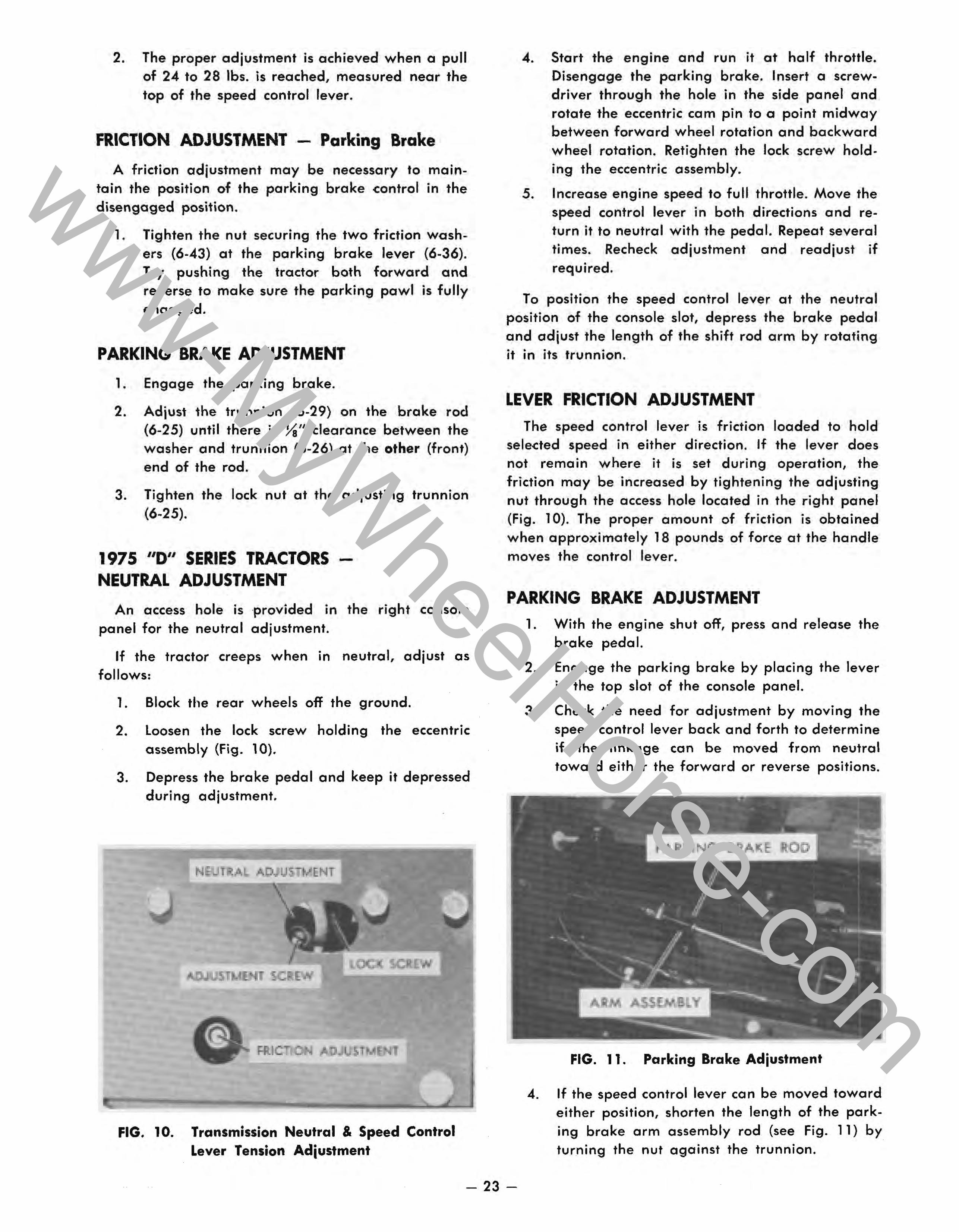
PARKING BRAKE ADJUSTMENT 1. With the engine shut off, press and release the
brake pedal.
2. Engage the parking brake by placing the lever in the top slot of the console panel.
3. Check the need for adjustment by moving the speed control lever back and forth to determine if the linkage can be moved from neutral toward either the forward or reverse positions.
FIG. 11. Parking Brake Adjustment
4. If the speed control lever can be moved toward either position, shorten the length of the parking brake arm assembly rod (see Fig. 11) by turning the nut against the trunnion.
- 23-
www-MyWheelHorse-com
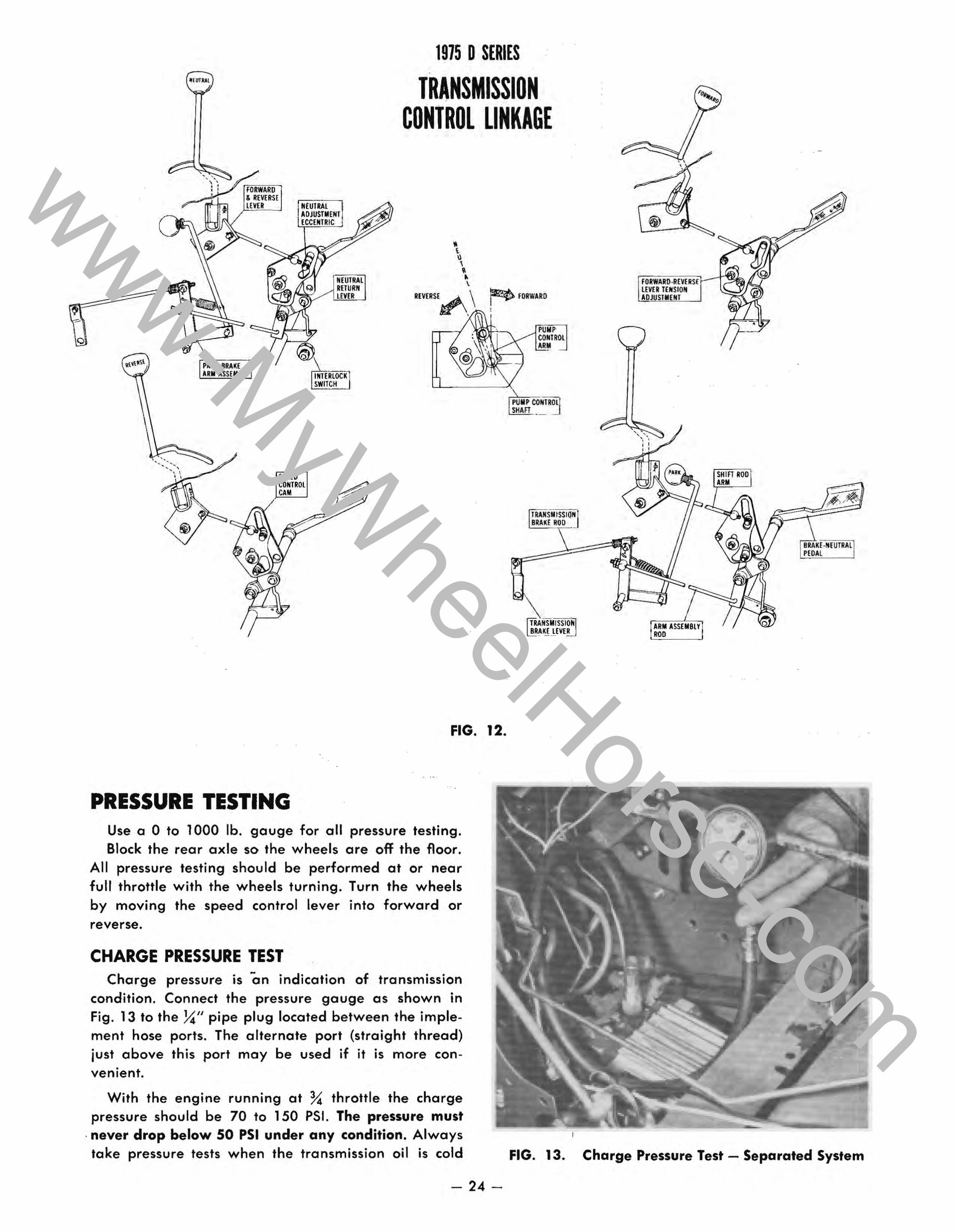
1975 0 SERIES
ON CONTROL LINKAGE
CONTROL
~ FORWARD ,
PUMP ...... 'COMTROl
...... , ARM
PUMP CONTROL/ SHAn -- -
FIG. 12.
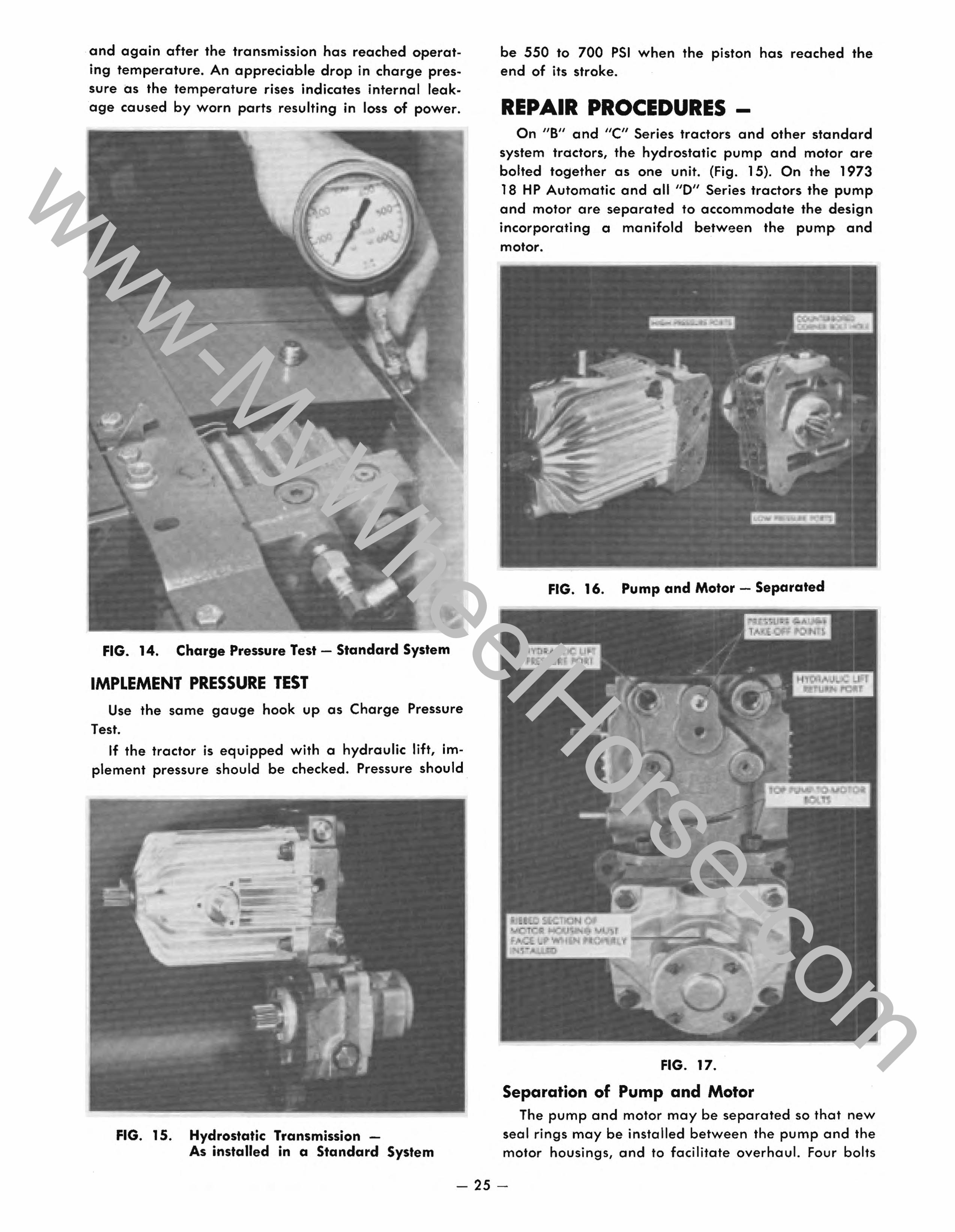
PRESSURE TESTING Use a a to 1000 lb. gauge for all pressure testing. Block the rear axle so the wheels are off the floor.
All pressure testing should be performed at or near full throttle with the wheels turning. Turn the wheels by moving the speed control lever into forward or reverse.
CHARGE PRESSURE TEST Charge pressure is on indication of transmission
condition. Connect the pressure gauge as shown in Fig. 13 to the ~" pipe plug located between the implement hose ports. The alternate port (straight thread) just above this port may be used if it is more convenient.
P[OAl
ASS[MBl Y ROO
With the engine running at % throttle the charge pressure should be 70 to 150 PSI. The pressure must
. never drop below 50 PSI under any condition. Always take pressure tests when the transmission oil is cold FIG. 13. Charge Pressure Test - Separated System
- 24-
www-MyWheelHorse-com
and again after the transmission has reached operating temperature. An appreciable drop in charge pressure as the temperature rises indicates internal leakage caused by worn parts resulting in loss of power.
FIG. 14. Charge Pressure Test - Standard System
IMPLEMENT PRESSURE TEST Use the same gauge hook up as Charge Pressure
Test.
If the tractor is equipped with a hydraulic lift, implement pressure should be checked. Pressure should
.-
FIG. 15. Hydrostatic Transmission -As installed in a Standard System
be 550 to 700 PSI when the piston has reached the end of its stroke.
PROCEDURES -On "8" and "C" Series tractors and other standard
system tractors, the hydrostatic pump and motor are bolted together as one unit. (Fig. 15). On the 1973 18 HP Automatic and all "0" Series tractors the pump and motor are separated to accommodate the design incorporating a manifold between the pump and motor.
FIG. 16. Pump and Motor - Separated
FIG. 17.
Separation of Pump and Motor The pump and motor may be separated so that new
seal rings may be installed between the pump and the motor housings, and to facilitate overhaul. Four bolts
- 25 -
www-MyWheelHorse-com
fasten the two units together. Two of the bolts are accessible from the top, and go down through the pump into the motor housing. The other two are accessible from the gasket side of the motor (where it attaches to the transaxle), and go up through the motor into the pump housing. Because "Allen" type screws are used, a ~6 inch hex Allen wrench is required.
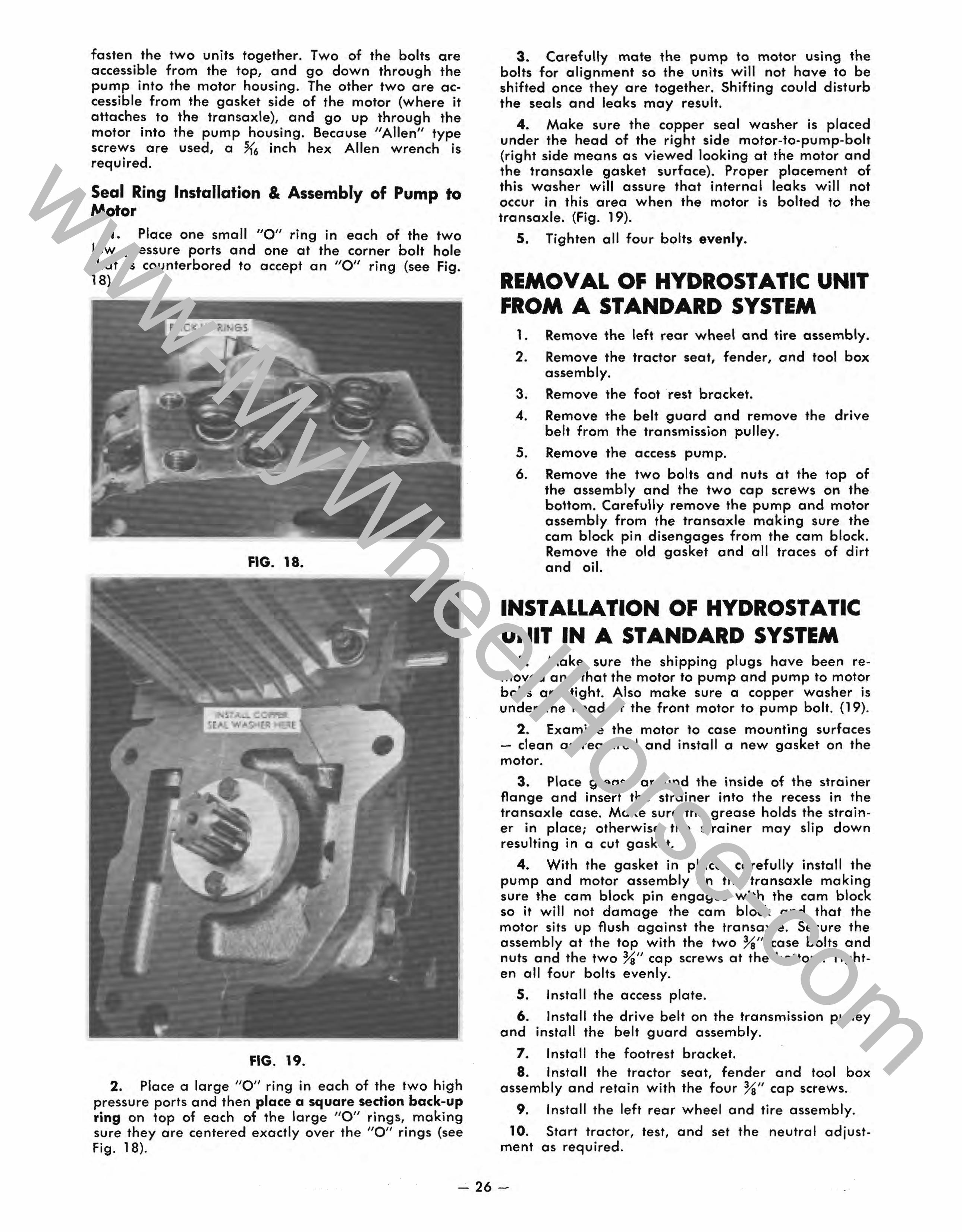
Seal Ring Installation & Assembly of Pump to Motor
1. Place one small "0" ring in each of the two low pressure ports and one at the corner bolt hole that is counterbored to accept an "0" ring (see Fig. 18).
FIG. 18.
FIG. 19.
2. Place a large "0" ring in each of the two high pressure ports and then place a square section back-up ring on top of each of the large "0" rings, making sure they are centered exactly over the "0" rings (see Fig. 18).
3. Carefully mate the pump to motor using the bolts for alignment so the units will not have to be shifted once they are together. Shifting could disturb the seals and leaks may result.
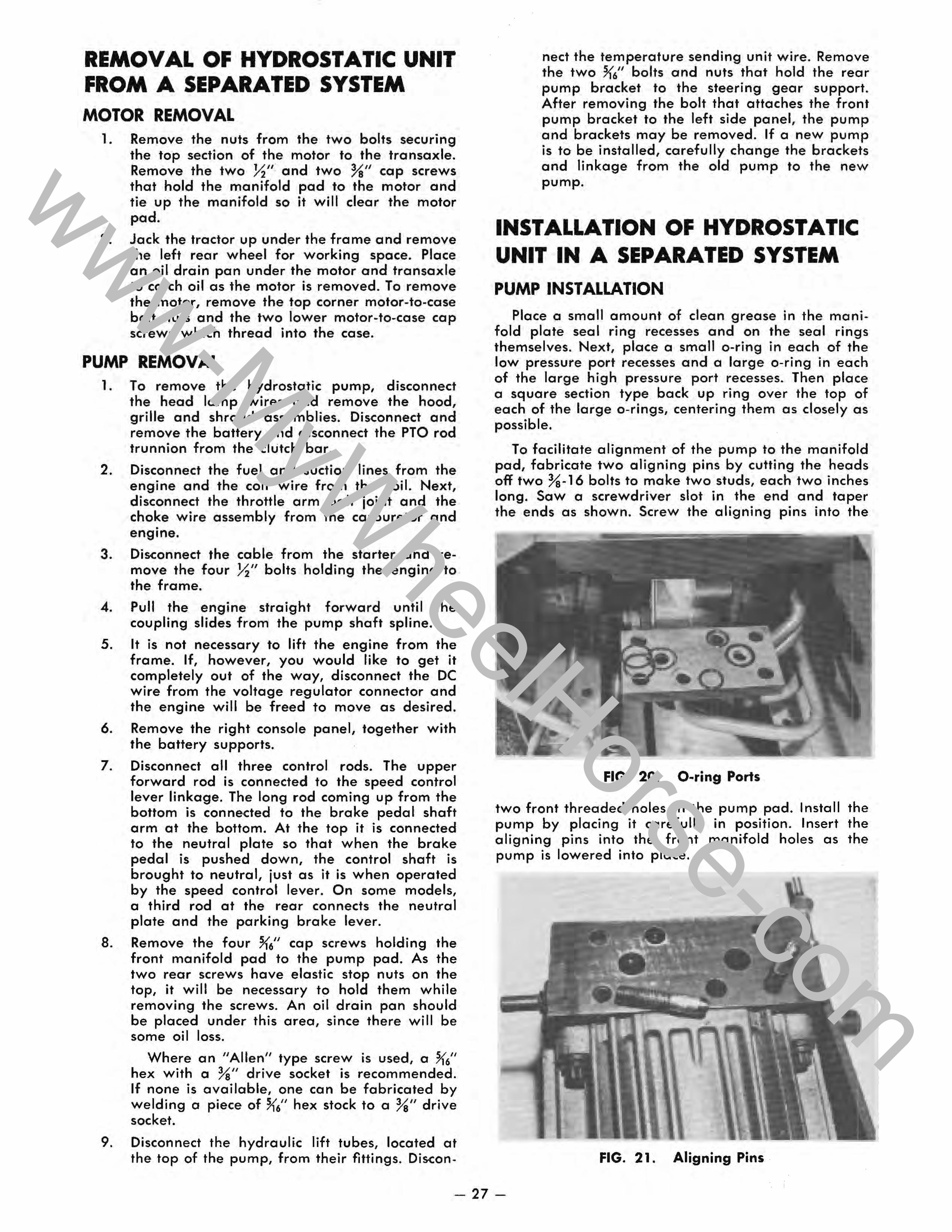
4. Make sure the copper seal washer is placed under the head of the right side motor-to·pump-bolt (right side means as viewed looking at the motor and the transaxle gasket surface). Proper placement of this washer will assure that internal leaks will not occur In this area when the motor is bolted to the transaxle. (Fig. 19).
5. Tighten all four bolts evenly.
REMOVAL OF HYDROSTATIC UNIT FROM A STANDARD SYSTEM
1. Remove the left rear wheel and tire assembly.
2. Remove the tractor seat, fender, and tool box assembly.
3. Remove the footrest bracket.
4. Remove the belt guard and remove the drive belt from the transmission pulley.
5. Remove the access pump.
6. Remove the two bolts and nuts at the top of the assembly and the two cap screws on the bottom. Carefully remove the pump and motor assembly from the transaxle making sure the cam block pin disengages from the cam block. Remove the old gasket and all traces of dirt and oil.
INSTALLATION OF HYDROSTATIC UNIT IN A STANDARD SYSTEM
1. Make sure the shipping plugs have been removed and that the motor to pump and pump to motor bolts are tight. Also make sure a copper washer is under the head of the front motor to pump bolt. (19).
2. Examine the motor to case mounting surfaces - clean as required and install a new gasket on the motor.
3. Place grease around the inside of the strainer flange and insert the strainer into the recess in the transaxle case. Make sure the grease holds the strainer in place; otherwise the strainer may slip down resulting in a cut gasket.
4. With the gasket in place, carefully install the pump and motor assembly on the transaxle making sure the cam block pin engages with the cam block so it will not damage the cam block and that the motor sits up flush against the transaxle. Secure the assembly at the top with the two Ys" case bolts and nuts and the two Ys" cap screws at the bottom. Tighten all four bolts evenly.
5. Install the access plate.
6. Install the drive belt on the transmission pulley and install the belt guard assembly.
7. Install the footrest bracket. 8. Install the tractor seat, fender and tool box
assembly and retain with the four Ys" cap screws.
9. Install the left rear wheel and tire assembly.
10. Start tractor, test, and set the neutral adjustment as required.
- 26-
www-MyWheelHorse-com
REMOVAL OF HYDROSTATIC UNIT FROM A ARATED SYSTEM MOTOR REMOVAL
1. Remove the nuts from the two bolts securing the top section of the motor to the transaxle. Remove the two ~II and two %/1 cap screws that hold the manifold pad to the motor and tie up the manifold so it will clear the motor pad.
2. Jack the tractor up under the frame and remove the left rear wheel for working space. Place an oil drain pan under the motor and transaxle to catch oil as the motor is removed. To remove the motor, remove the top corner motor-to-case bolt nuts and the two lower motor-to-case cap screws which thread into the case.
PUMP REMOVAL 1. To remove the hydrostatic pump, disconnect
the head lamp wires and remove the hood, grille and shroud assemblies. Disconnect and remove the battery and disconnect the PTO rod trunnion from the clutch bar.
2. Disconnect the fuel and suction lines from the engine and the coil wire from the coil. Next, disconnect the throttle arm ball joint and the choke wire assembly from the carburetor and
• engine.
3. Disconnect the cable from the starter and remove the four ~/I bolts holding the engine to the frame.
4. Pull the engine straight forward until the coupling slides from the pump shaft spline.
5. It is not necessary to lift the engine from the frame. If, however, you would like to get it completely out of the way, disconnect the DC wire from the voltage regulator connector and the engine will be freed to move as desired.
6. Remove the right console panel, together with the battery supports.
7. Disconnect all three control rods. The upper forward rod is connected to the speed control lever linkage. The long rod coming up from the bottom is connected to the brake pedal shaft arm at the bottom. At the top it is connected to the neutral plate so that when the brake pedal is pushed down, the control shaft is brought to neutral, just as it is when operated by the speed control lever. On some models, a third rod at the rear connects the neutral plate and the parking brake lever.
8. Remove the four U6/1 cap screws holding the front manifold pad to the pump pad. As the two rear screws have elastic stop nuts on the top, it will be necessary to hold them while removing the screws. An oil drain pan should be placed under this area, since there will be some oil loss.
Where an /lAlien" type screw is used, a U6" hex with a Ye" drive socket is recommended. If none is available, one can be fabricated by welding a piece of U/' hex stock to a Ye" drive socket.
9. Disconnect the hydraulic lift tubes, located at the top of the pump, from their fittings. Discon-
nect the temperature sending unit wire. Remove the two U6/1 bolts and nuts that hold the rear pump bracket to the steering gear support. After removing the bolt that attaches the front pump bracket to the left side panel, the pump and brackets may be removed. If a new pump is to be installed, carefully change the brackets and linkage from the old pump to the new pump.
INSTALLATION OF HYDROSTATIC UNIT IN A SEPARATED SYSTEM
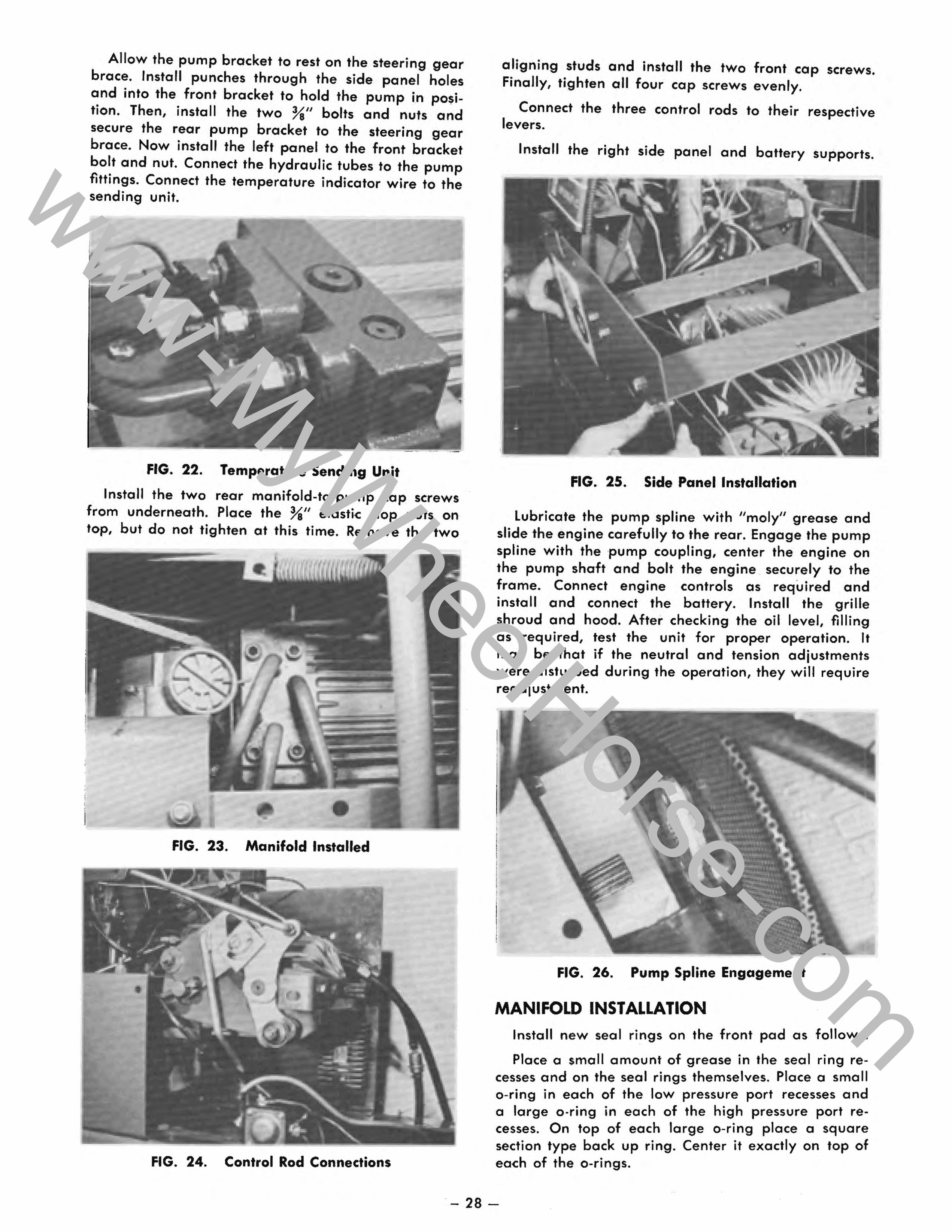
PUMP INSTALLATION Place a small amount of clean grease in the mani
fold plate seal ring recesses and on the seal rings themselves. Next, place a small o-ring in each of the low pressure port recesses and a large o-ring in each of the large high pressure port recesses. Then place a square section type back up ring over the top of each of the large o-rings, centering them as closely as possible.
To facilitate alignment of the pump to the manifold pad, fabricate two aligning pins by cutting the heads off two %-16 bolts to make two studs, each two inches long. Saw a screwdriver slot in the end and taper the ends as shown. Screw the aligning pins into the
FIG. 20. O-ring Ports
two front threaded holes in the pump pad. Install the pump by placing it carefully in position. Insert the aligning pins into the front manifold holes as the pump is lowered into place.
FIG. 21. Aligning Pins
- 27-
www-MyWheelHorse-com
Allow the pump bracket to rest on the steering gear brace. Install punches through the side panel holes and into the front bracket to hold the pump in position. Then, install the two %" bolts and nuts and secure the rear pump bracket to the steering gear brace. Now install the left panel to the front bracket bolt and nut. Connect the hydraulic tubes to the pump fittings. Connect the temperature indicator wire to the sending unit.
FIG. 22. Temperature Sending Unit
Install the two rear manifold-to-pump cap screws from underneath. Place the %" elastic stop nuts on top, but do not tighten at this time. Remove the two
FIG. 23. Manifold Installed
FIG. 24. Control Rod Connections
aligning studs and install the two front cap screws. Finally, tighten all four cap screws evenly.
Connect the three control rods to their respective levers.
Install the right side panel and battery supports.
FIG. 25. Side Panel Installation
Lubricate the pump spline with "moly" grease and slide the engine carefully to the rear. Engage the pump spline with the pump coupling, center the engine on the pump shaft and bolt the engine . securely to the frame. Connect engine controls as required and install and connect the battery. Install the grille shroud and hood. After checking the oil level, filling as required, test the unit for proper operation. It may be that if the neutral and tension adjustments were disturbed during the operation, they will require readjustment.
FIG. 26. Pump Spline Engagement
MANIFOLD INSTALLATION Install new seal rings on the front pad as follows:
Place a small amount of grease in the seal ring recesses and on the seal rings themselves. Place a small o-ring in each of the low pressure port recesses and a large o·ring in each of the high pressure port recesses. On top of each large o-ring place a square section type back up ring. Center it exactly on top of each of the o-rings.
- 28-
www-MyWheelHorse-com
FIG. 27. Ring Installation
Place a protective cardboard cover over the seal rings to hold them in place and keep the .area free from dirt during installation.
FIG. 28. Protected Seal Rings
The following photograph shows the location of the seal rings and manifold attaching bolts at the hydraulic motor pad. NOTE: Two %" bolts and washers are at the left side of the pad and two ~" bolts at the right side. Also note that the rear ~" bolt does not use a washer. The front ~II bolt, however, requires a special seal washer. Also, an o-ring is used at this corner between the manifold and the motor pad. These extra seals are required since this bolt goes down into a pressure area. If it is not sealed, there will be a major oil leak. Before installing seal rings, place a small amount of grease in each recess and on all seal rings. Place one small o-ring in each of the two low pressure ports and one at the right front bolthole recess. Place a large o-ring in each of the high pressure ports and then place a square section back up ring exactly over the top of each of the large o-rings. Make sure no dirt or foreign matter falls into this area while installing the manifold.
Prior to installing the manifold examine it carefully for cracks around the tubing welds and make sure the clamp prevents the tubes from flexing. If the tubes can be moved in the clamp, remove the clamps
FIG. 29. Ring and Bolt Locations
and shape them as required to hold the tubes firmly. The following photograph shows the front of the manifold as it is inserted past the steering gear bracket turned to position it for attachment to the pump pad. Leave the protective cover on this pad while the rear of the manifold is being connected to the hydraulic motor.
• -J
FIG. 30. Positioning the Manifold
FIG. 31. Rear Manifold Pad in Place
- 29-
www-MyWheelHorse-com
Carefully hold the manifold in place. Align the bolt holes in the manifold pad with the bolt holes in %e motor and install all four bolts. Make sure that the special seal washer is under the head of the right front ~" bolt. Do not completely tighten the bolts at this time. Just leave them snug so that the front of the .,
manifold may be aligned without distorting the tubes.
Remove the protective cover from the front manifold pad and check to make sure all seal rings are in place. This can be done by flexing the tubes down just enough to feel if all the o-rings and back up rings are in place. Position the manifold pad so the bolt holes line up and install the two short front hex screws. leave them loose at this time. Install the two longer bolts in the two rear holes, with the elastic stop nuts on top. Tighten all four bolts evenly, holding the nuts on the rear bolts as required. Now tighten all four of the rear manifold pad-to-motor bolts.
FIG. 32. Manifold Installed
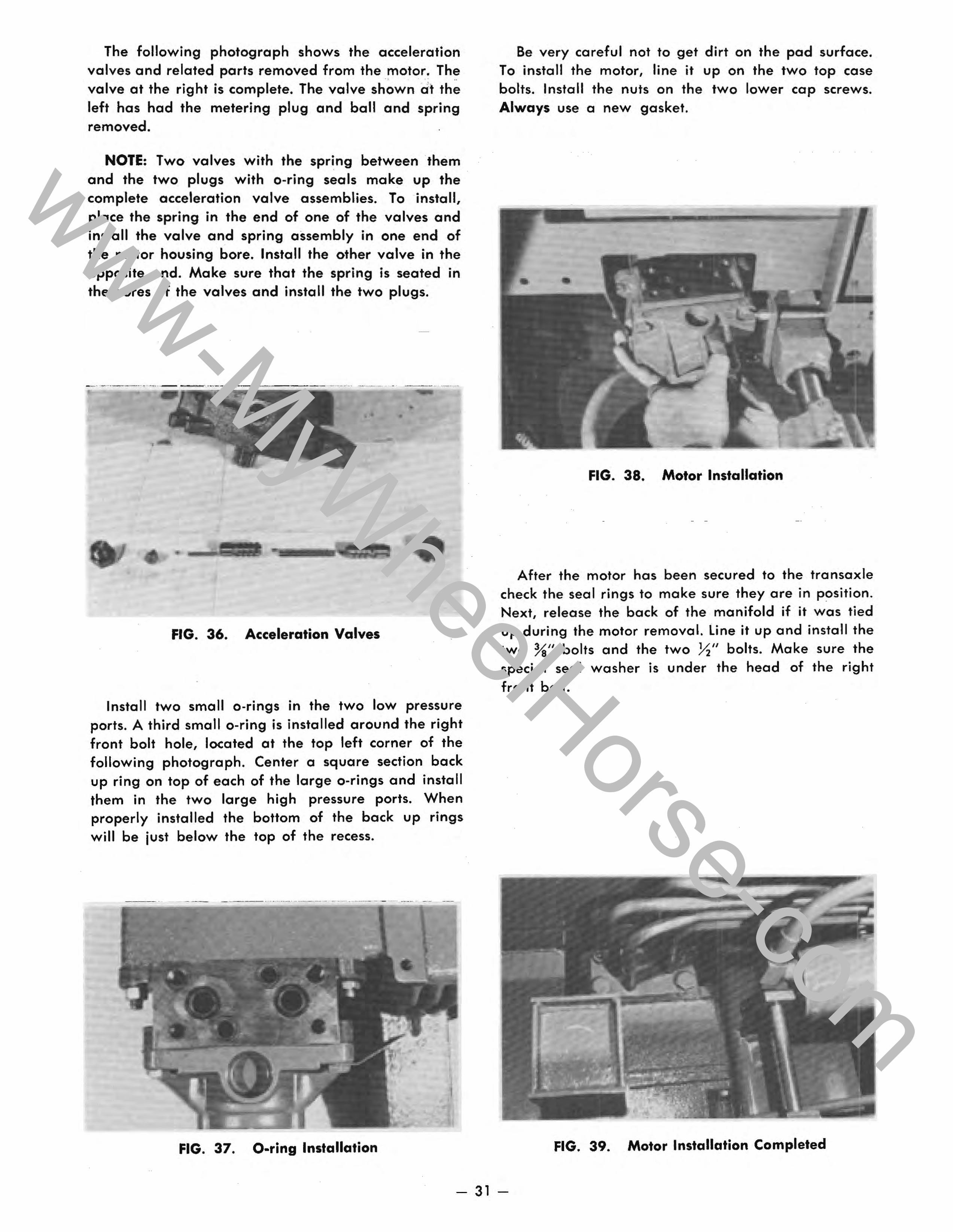
Install the seat spring on its support and install the spring block on top of the spring.
FIG. 33. Spring and Block
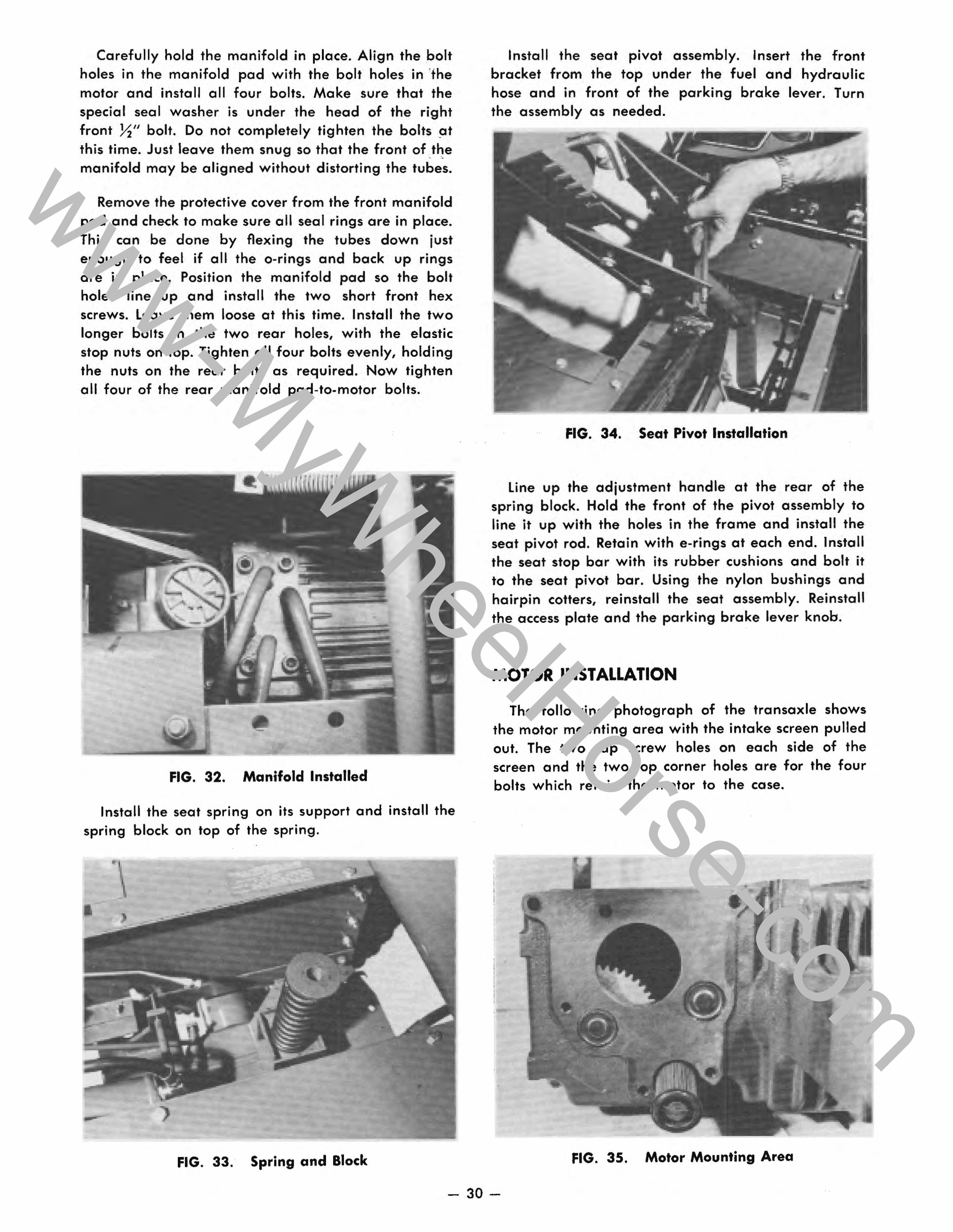
Install the seat pivot assembly. Insert the front bracket from the top under the fuel and hydraulic hose and in front of the parking brake lever. Turn the assembly as needed.
FIG. 34. Seat Pivot Installation
line up the adjustment handle at the rear of the spring block. Hold the front of the pivot assembly to line it up with the holes in the frame and install the seat pivot rod. Retain with e-rings at each end. Install the seat stop bar with its rubber cushions and bolt it to the seat pivot bar. Using the nylon bushings and hairpin cotters, reinstall the seat assembly. Reinstall the access plate and the parking brake lever knob.
MOTOR INSTALLATION
The following photograph of the transaxle shows the motor mounting area with the intake screen pulled out. The two cap screw holes on each side of the screen and the two top corner holes are for the four bolts which retain the motor to the case.
FIG. 35. Motor Mounting Area
- 30-
www-MyWheelHorse-com
The following photograph shows the acceleration valves and related parts removed from the motor. The valve at the right is complete. The valve shown dt the left has had the metering plug and ball and spring removed.
NOTE: Two valves with the spring between them and the two plugs with a-ring seals make up the complete acceleration valve assemblies. To install, place the spring in the end of one of the valves and install the valve and spring assembly in one end of the motor housing bore. Install the other valve in the opposite end. Make sure that the spring is seated in the bores of the valves and install the two plugs.
-... _._ ........ ... .... = == .. -.--.-------.. = = - .. -...... ~ ..... ... ;;.:,. ~ .... ;;;;; ...... ..;;.......;,.,...;;;;;;- .~
•
•
FIG. 36. Acceleration Valves
Install two small a-rings in the two low pressure ports. A third small a-ring is installed around the right front bolt hole, located at the top left corner of the following photograph. Center a square section back up ring on top of each of the large a-rings and install them in the two large high pressure ports. When properly installed the bottom of the back up rings will be just below the top of the recess.
FIG. 37. O·ring Installation
Be very careful not to get dirt on the pad surface. To install the motor, line it up on the two top case bolts. Install the nuts on the two lower cap screws. Always use a new gasket.
FIG. 38. Motor Installation
After the motor has been secured to the transaxle check the seal rings to make sure they are in position. Next, release the back of the manifold if it was tied up during the motor removal. line it up and install the two Ye" bolts and the two ~" bolts. Make sure the special seal washer is under the head of the right front bolt.
FIG. 39. Motor Installation Completed
- 31 -
www-MyWheelHorse-com
INSPECTION OF PARTS All parts should be thoroughly cleaned and exam
ined. After examining, cover all parts with a lint-free cloth while waiting for assembly. Oil all moving parts with 10W30 premium engine oil when assembling.
FIG. 40.
Pump and Motor Shafts Examine the bearing and seal surfaces of the shafts.
Scored or worn shafts must be replaced. Pay particular attention to the pump shaft seal area. A scratched seal area will cause an oil leak.
Cylinder Block Assemblies - General Although the pump and motor cylinder block and
piston assemblies look similar, they differ. Two cylinder block kits, one for the pump and one for the motor, are available, and should be used for replacement when the following conditions are found:
FIG. 41.
1. Cylinder bores out of round or scored. 2. Cylinder block face (valving surface) worn,
scratched or scored. 3. Scored piston barrels. 4. Slipper edges rounded more than ~2 inch. When inspecting cylinder block assemblies always
return pistons to their original cylinder bores.
FIG. 42. Check Free Movement of Pistons
Check to make sure the pistons move freely in their bores. Carefully remove each piston and check for scores on the piston barrels and on the .cylinder bore walls. Replace with cylinder block kit if bores or barrels are scored.
Cylinder Block Face Inspect the polished valving surface of the cylinder
blocks. If the surface is scored replace with a cylinder block kit.
Pistons and Slippers Scored piston barrels and slippers with edges
rounded more than ~2 inch must not be used. Replace with a new cylinder block kit. Slight scratches on slippers or slightly rounded edges may be removed by lapping. Use crocus cloth for finishing. Do not remove more than .005". Make sure that all slippers are within .002" thickness of each other.
Make sure the lubrication hole is open in the center of the slipper face. Use compressed air to open.
FIG. 43.
- 32-
www-MyWheelHorse-com
Slipper Retainers
Slipper retainers must be flat. Examine them carefully. If bent or worn, replace them.
Valve Plates
Clean valve plates and check both sides of the plates. Remove any burrs or foreign matter from the steel side of the plate. Check the bronze side of the plate for scratches and wear. This surface must be smooth and free from scratches. To check the surface, run your fingernail across the plate. If wear is felt, replace the plate.
FIG. 44.
Thrust Plates Inspect both thrust plates (for the pump and motor
swash plates) for flatness, scoring and imbedded material. Replace as required.
FIG. 45. Inspect Thrust Plates
Charge Pump Assembly Inspect the gerotor set (internal and external rotors),
and the housing, for wear and scoring. Replace as required. Note: The gerotor set is a matched unit. Always replace as an assembly. If the charge pump housing is worn or scored, it must be replaced.
Bearings (for replacement see Disassembly and Assembly section)
Examine the needle bearings in the pump and motor end caps and replace as required. Examine the ball bearings in the pump and motor housings and replace as required.
- 33-
www-MyWheelHorse-com
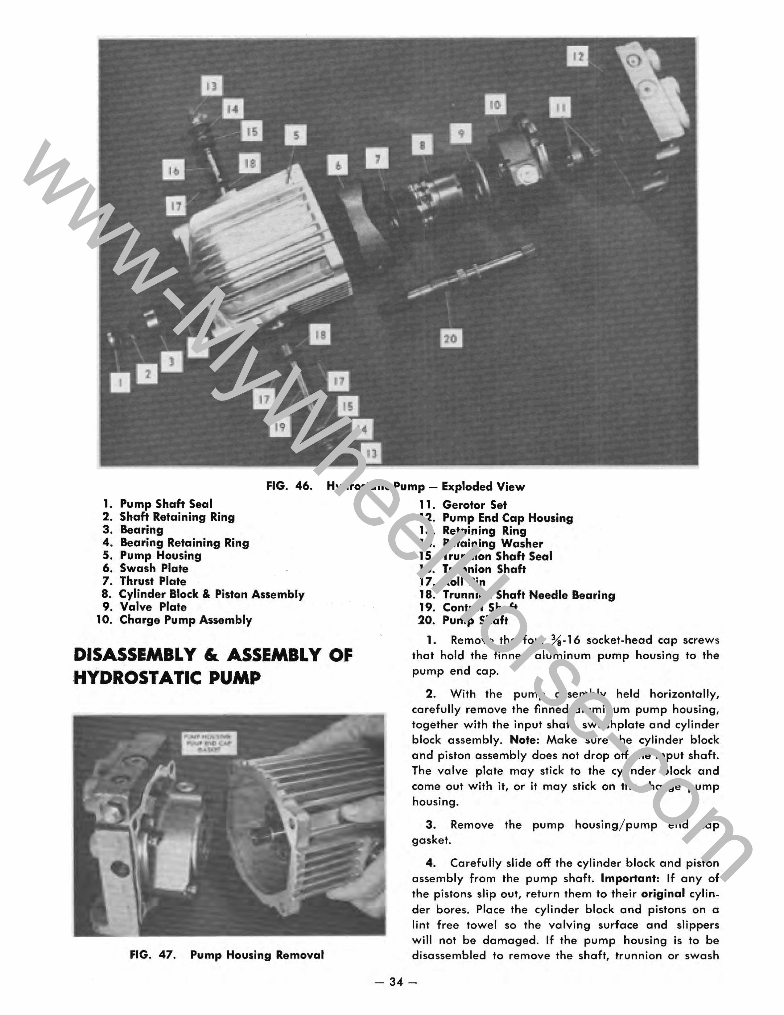
FIG. 46. Hydrostatic Pump - Exploded View
1. Pump Shaft Seal 2. Shaft Retaining Ring 3. Bearing 4. Bearing Retaining Ring 5. Pump Housing 6. Swash Plate 7. Thrust Plate 8. Cylinder Block & Piston Assembly 9. Valve Plate
10. Charge Pump Assembly
DISASSEMBLY & ASSEMBLY OF HYDROSTATIC PUMP
FIG. 47. Pump Housing Removal
11. Gerotor Set 12. Pump End Cap Housing 13. Retaining Ring 14. Retaining Washer 15. Trunnion Shaft Seal 16. Trunnion Shaft 17. Roll Pin 18. Trunnion Shaft Needle Bearing 19. Control Shaft 20. Pump Shaft
1. Remove the four %.16 socket·head cap screws that hold the finned aluminum pump housing to the pump end cap.
2. With the pump assembly held horizontally, carefully remove the finned aluminum pump housing, together with the input shaft, swash plate and cylinder block assembly. Note: Make sure the cylinder block and piston assembly does not drop off the input shaft. The valve plate may stick to the cylinder block and come out with it, or it may stick on the charge pump housing.
3. Remove the pump housing/pump end cap gasket.
4. Carefully slide off the cylinder block and piston assembly from the pump shaft. Important: If any of the pistons slip out, return them to their original cylin. der bores. Place the cylinder block and pistons on a lint free towel so the valving surface and slippers will not be damaged. If the pump housing is to be disassembled to remove the shaft, trunnion or swash
- 34-
www-MyWheelHorse-com
plate, refer to the Pump Housing Disassembly and Assembly section.
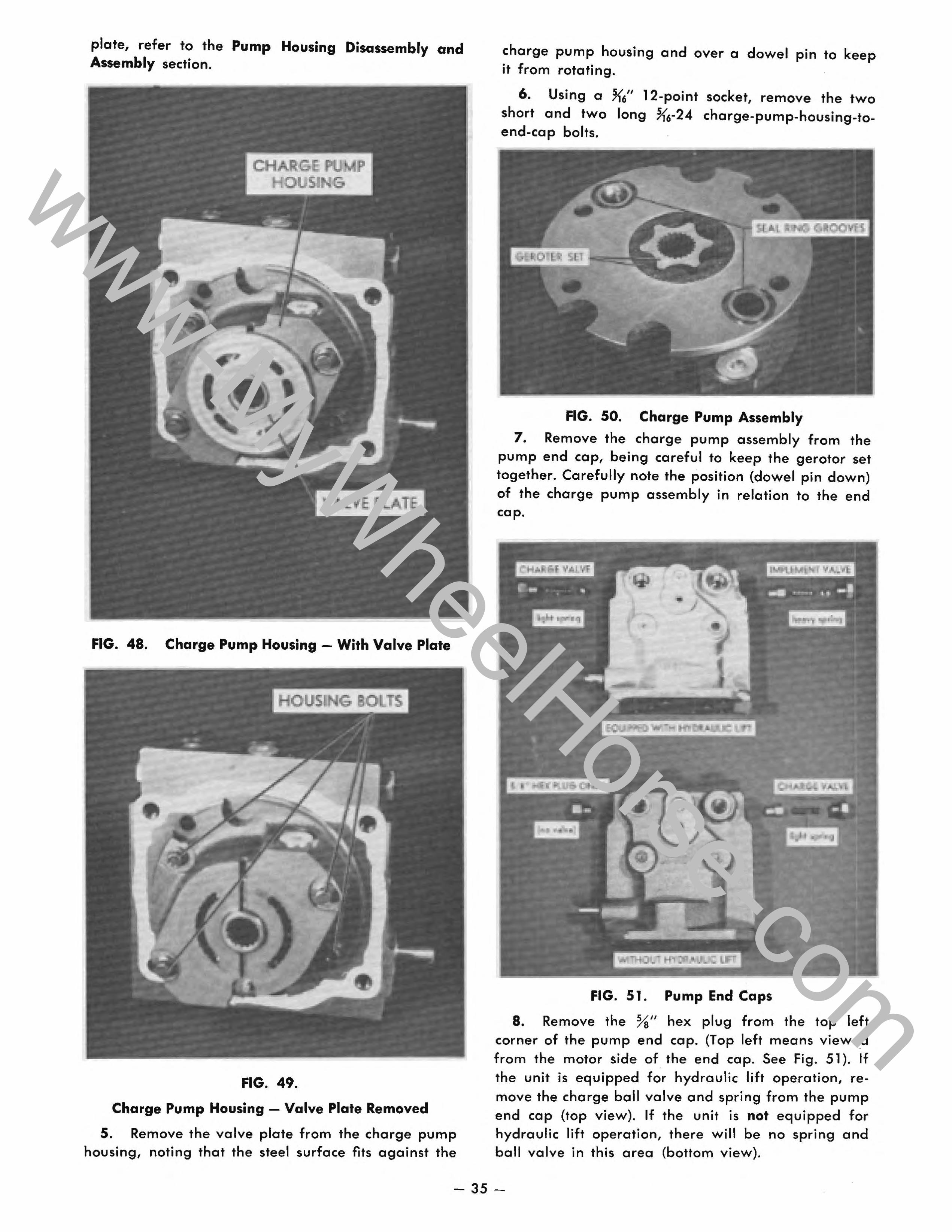
FIG. 48. Charge Pump Housing - With Valve Plate
FIG. 49.
Charge Pump Housing - Valve Plate Removed
5. Remove the valve plate from the charge pump housing, noting that the steel surface fits against the
charge pump housing and over a dowel pin to keep it from rotating.
6. Using a ~6" 12-point socket, remove the two short and two long ~6-24 charge-pump-housing-toend-cap bolts.
FIG. 50. Charge Pump Assembly
7. Remove the charge pump assembly from the pump end cap, being careful to keep the gerotor set together. Carefully note the position (dowel pin down) of the charge pump assembly in relation to the end cap.
FIG. 51. Pump End Caps
8. Remove the %" hex plug from the top left corner of the pump end cap. (Top left means viewed from the motor side of the end cap. See Fig. 51). If the unit is equipped for hydraulic lift operation, remove the charge ball valve and spring from the pump end cap (top view). If the unit is not equipped for hydraulic lift operation, there will be no spring and ball valve in this area (bottom view).
- 35-
www-MyWheelHorse-com
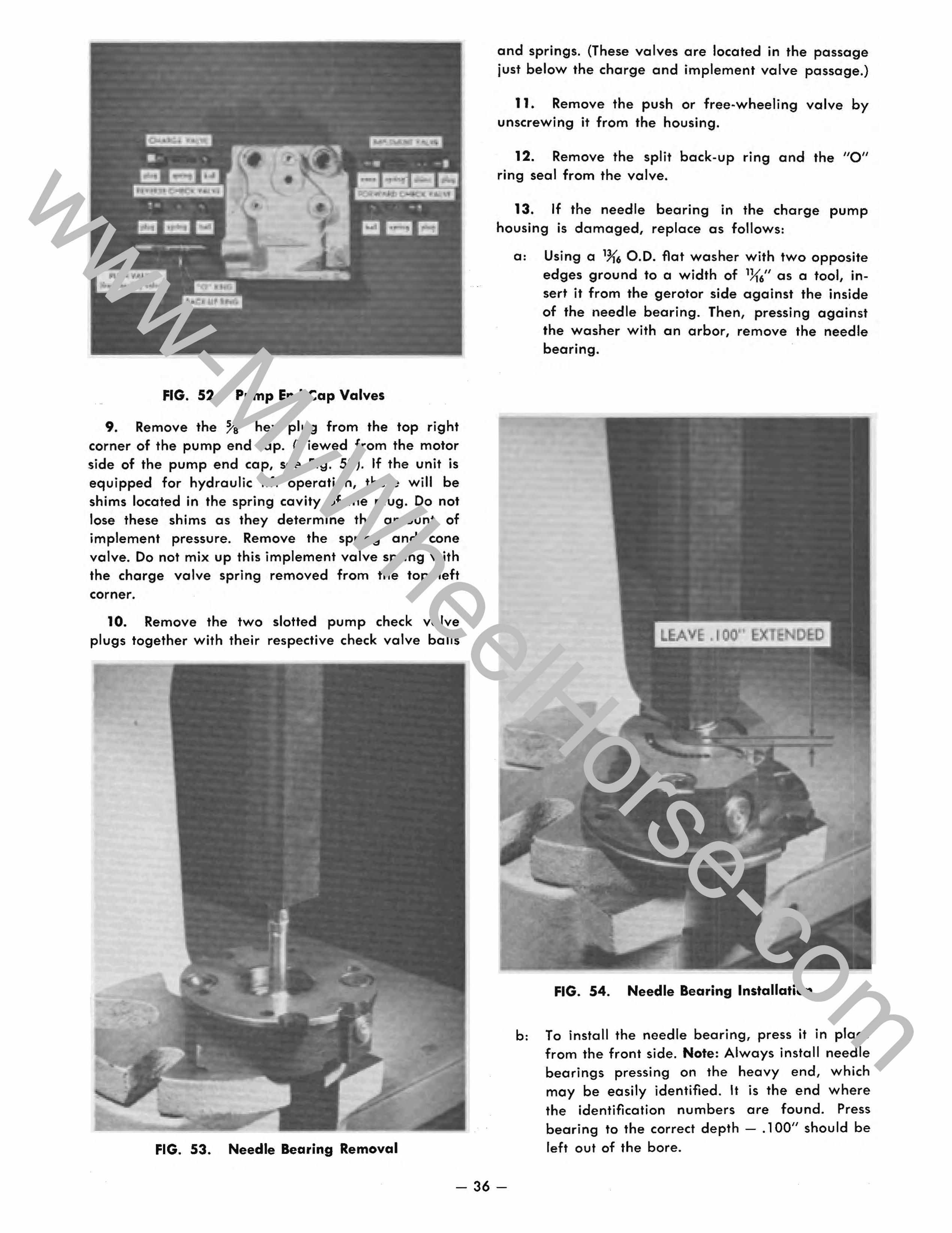
FIG. 52. Pump End Cap Valves
9. Remove the %" hex plug from the top right corner of the pump end cap. (Viewed from the motor side of the pump end cap, see Fig. 52). If the unit is equipped for hydraulic lift operation, there will be shims located in the spring cavity of the plug. Do not lose these shims as they determine the amount of implement pressure. Remove the spring and cone valve. Do not mix up this implement valve spring with the charge valve spring removed from the top left corner.
10. Remove the two slotted pump check valve plugs together with their respective check valve balls
FIG. 53. Needle Bearing Removal
and springs. (These valves are located in the passage just below the charge and implement valve passage.)
11. Remove the push or free-wheeling valve by unscrewing it from the housing.
12. Remove the split back-up ring and the "0" ring seal from the valve.
13. If the needle bearing in the charge pump housing is damaged, replace as follows:
a: Using a 1~6 0.0. flat washer with two opposite edges ground to a width of 1){6" as a tool, insert it from the gerotor side against the inside of the needle bearing. Then, pressing against the washer with an arbor, remove the needle bearing.
FIG. 54. Needle Bearing Installation
b: To install the needle bearing, press it in place from the front side. Note: Always install needle bearings pressing on the heavy end, which may be easily identified. It is the end where the identification numbers are found. Press bearing to the correct depth - .100" should be left out of the bore.
- 36-
www-MyWheelHorse-com
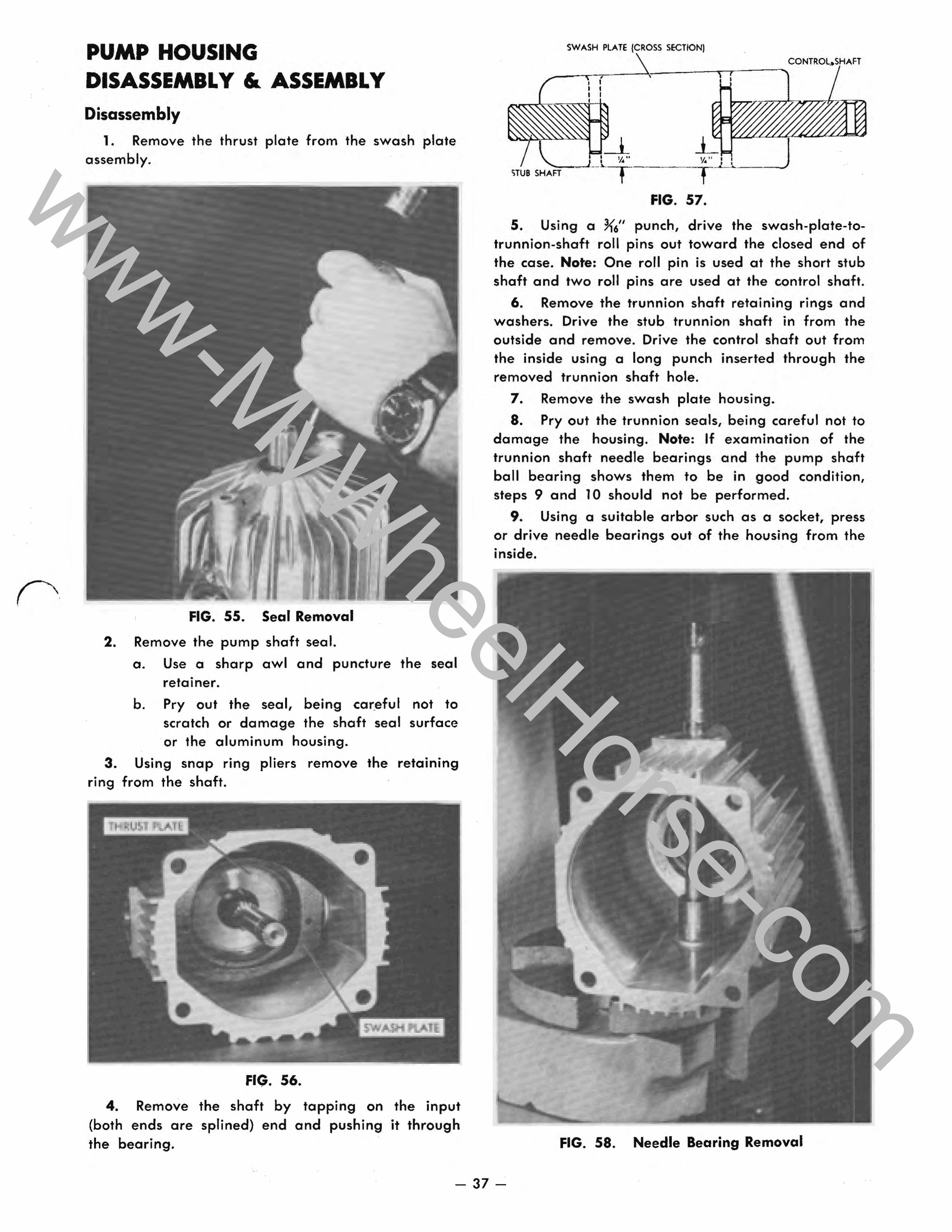
PUMP HOUSING DISASSEMBL Y & ASSEMBLY Disassembly
1. Remove the thrust plate from the swash plate assembly.
FIG. 55. Seal Removal
2. Remove the pump shaft seal.
a. Use a sharp awl and puncture the seal retainer.
b. Pry out the seal, being careful not to scratch or damage the shaft seal surface or the aluminum housing.
3. Using snap ring pliers remove the retaining ring from the shaft.
FIG. 56.
4. Remove the shaft by tapping on the input (both ends are splined) end and pushing it through the bearing.
SWASH PLATE {CROSS SECTIONI
CONTROL.SHAFT
__ ~,--~---~T,--I I I I
Io=!~ I V. .. 11 " I I "":::-_ " • - _ __ -Cy"_--l'-""-___ J
,TUB SHAFT J--~T t . . FIG. 57.
5. Using a K6" punch, drive the swash-plate-totrunnion-shaft roll pins out toward the closed end of the case. Note: One roll pin is used at the short stub shaft and two roll pins are used at the control shaft.
6. Remove the trunnion shaft retaining rings and washers. Drive the stub trunnion shaft in from the outside and remove. Drive the control shaft out from the inside using a long punch inserted through the removed trunnion shaft hole.
7. Remove the swash plate housing.
S. Pry out the trunnion seals, being careful not to damage the housing. Note: If examination of the trunnion shaft needle bearings and the pump shaft ball bearing shows them to be in good condition, steps 9 and 10 should not be performed.
9. Using a suitable arbor such as a socket, press or drive needle bearings out of the housing from the inside.
FIG. 58. Needle Bearing Removal
- 37-
www-MyWheelHorse-com
10. With snap ring pliers, remove the internal retaining ring that retains the pump shaft ball bearing in the pump housing, then remove the bearing by pressing it toward the inside of the housing.
Assembly of Pump Housing 1. Install pump shaft ball bearing in the front of
the pump housing and retain with the internal tru-arc •• • retaining ring.
2. Note: Only if needle bearings have been re.moved, install the two trunnion shaft needle bearings from the outside, pushing on the lettered end of the bearing. The bearings should be pressed in flush with the bottom of the seal bore so they will not interfere with the seal installation.
FIG. 59. Needle Bearing Installation
3. I nstall new trunnion shaft seals, pressing them in until they touch bottom. Oil the seal lips with 10W30 engine oil.
. 4. Insert the swash plate assembly into the case. Slide the trunnion shafts into each side, and into the swash plate housing. Line up the roll pin holes and install the roll pins. One roll pin is used at the short trunnion shaft and two roll pins are used at the control shaft. Drive the first pin in so it enters into the for side of the swash plate. Then drive the second roll pin down against the first pin until it is ~" below the surface of the swash plate. Drive the single roll pin at the short trunnion side so that it is ~" below the surface. See Fig. 57.
5. Install the trunnion seal washers and the retain-• • mg rings.
6. Install the pump shaft by tapping it through the bearing from the inside and retain it with the external snap ring.
1. Lubricate the pump shaft seal and install over the pump shaft with the lip side toward the pump. Press it in place so that it is flush with the outside of the housing.
Assembly of Pump Section 1. Install a new "0" ring seal and new back-up
ring on the free wheeling valve, making sure the seal is toward the pump housing and the split back-up ring is toward the outside. Install the valve assembly.
FIG. 60. Pump End Cap Valves
2. Install both pump check valve balls and springs, together with their slotted plugs and "0" ring seals.
3. Viewed from the motor side of the pump end cap, install charge relief valve and implement valve parts.
FIG. 61. Pump End Caps
o. Models not equipped for hydraulic lift: 1. Install the hex head plug and new "Oil
ring seal in the top left corner of the pump end cap.
- 38-
www-MyWheelHorse-com
2. Install the cone valve, charge valve spring together with the hex head plug, and new "0" ring seal in the top right corner of the pump end cap.
b. Models equipped for hydraulic lift:
1. Install the "K6" ball valve and spring together with the hex plug and "0" ring in the top left corner of the pump end cap.
2. Install the cone valve and spring in the top right corner of the pump end cap, then, making sure that the original shim pack is in the spring cavity of the plug, install the plug, "0" ring and shim assembly.
FIG. 62. Charge Pump Assembly
4. Install the gerotor set in the charge pump housing and install the pump housing and gerotor assembly on the pump end cap using new seal rings ("0" rings and back up rings) with the valve plate dowel pin toward the bottom. Install the two long and two short bolts and tighten evenly.
FIG. 63. Charge Pump Housing
5. Install the valve plate on the charge pump housing, centering it around the needle bearing with the steel face of the plate against the charge pump housing and the slot over the dowel pin to keep it from turning. Mounted properly, the plate should be flush against the housing so the cylinder block will operate on the bronze surface.
FIG. 64. Charge Pump Housing - With Valve Plate
6. Install a new pump-housing-to-end-cap gasket on the pump end cap.
FIG. 65.
7. Apply oil to the thrust plate and place it on the swash plate.
- 39-
www-MyWheelHorse-com
FIG. 66.
8. lay the pump end cap on a flat surface and install the cylinder block w'ith the piston and slipper assembly on the valve plate.
9. Center the charge pump gerotor drive so the pump shaft and spline can enter it.
FIG. 67. Pump Housing Installation
10. Making sure the control shaft is on the correct side, carefully install the aluminum pump housing and shaft so the shaft spline enters the cylinder block and gerotor drive. Install the four pump housing cap screws to align the pump, gasket and end cap. Push the pump housing in place (it may be necessary to turn the pump shaft t,o align it with the charge pump spline). After the housing and shaft are pushed in place, tighten the four bolts evenly.
REMOVAL & REPLACEMENT OF ACCELERATION VALVES
NOTE: Although the acceleration valves look similar, they are not alike. The forward valve, located at the rear of the end cap housing, incorporates wider relief flats on the valve lands than does the reverse valve, located at the front of the end cap housing.
o LYE
FIG. 68. Acceleration Valves
- 40-
www-MyWheelHorse-com
1. Remove the Ye" hex head plug from each side of the motor end cap.
,
FIG. 69.
2. Remove the first valve by pulling it out. Remove the second valve by pushing it out with the spring and remove the spring. NOTE: To simplify removal of the forward valve, located at the rear of the end cap housing, move the tractor about an inch and oil pressure will force the volve to pop out.
FIG. 70.
3. The acceleration valves may be disassembled for inspection and cleaning.
Disassembly a. Carefully hold the valve body wrapped in a
cloth to protect it. Remove the metering plug, ball and spring.
Assembly
Important:
a. Make sure the small metering plug orifice in side of the metering plug is open. (Fig. 70).
b. Seat the ball in the end of the metering plug and install the spring and metering plug.
4. Install the forward acceleration valve assembly (the one with the wider relief flats) in the bore at the rear of the end cap housing.
Insert the reverse acceleration valve assembly (the one with the narrow relief flats) together with the spring into the bore at the front of the end cap housing.
Make sure the spring seats in the spring cavity of each valve. When properly seated each valve will have approximately four or five threads exposed so the Ye" hex plugs may be easily installed.
5. Install both plugs using new "0" ring seals and tighten securely.
DISASSEMBLY AND ASSEMBLY OF HYDROSTATIC MOTOR Disassembly of Motor
1. Remove the four 10·24 Allen head cap screws that retain the cover plate, and remove the cover plate.
2. Remove the large "0" ring seal from around the boll bearing.
FIG. 71. Remove Snap Ring from Motor Shaft
3. Remove the snap ring from the end of the motor shaft.
- 41 -
www-MyWheelHorse-com
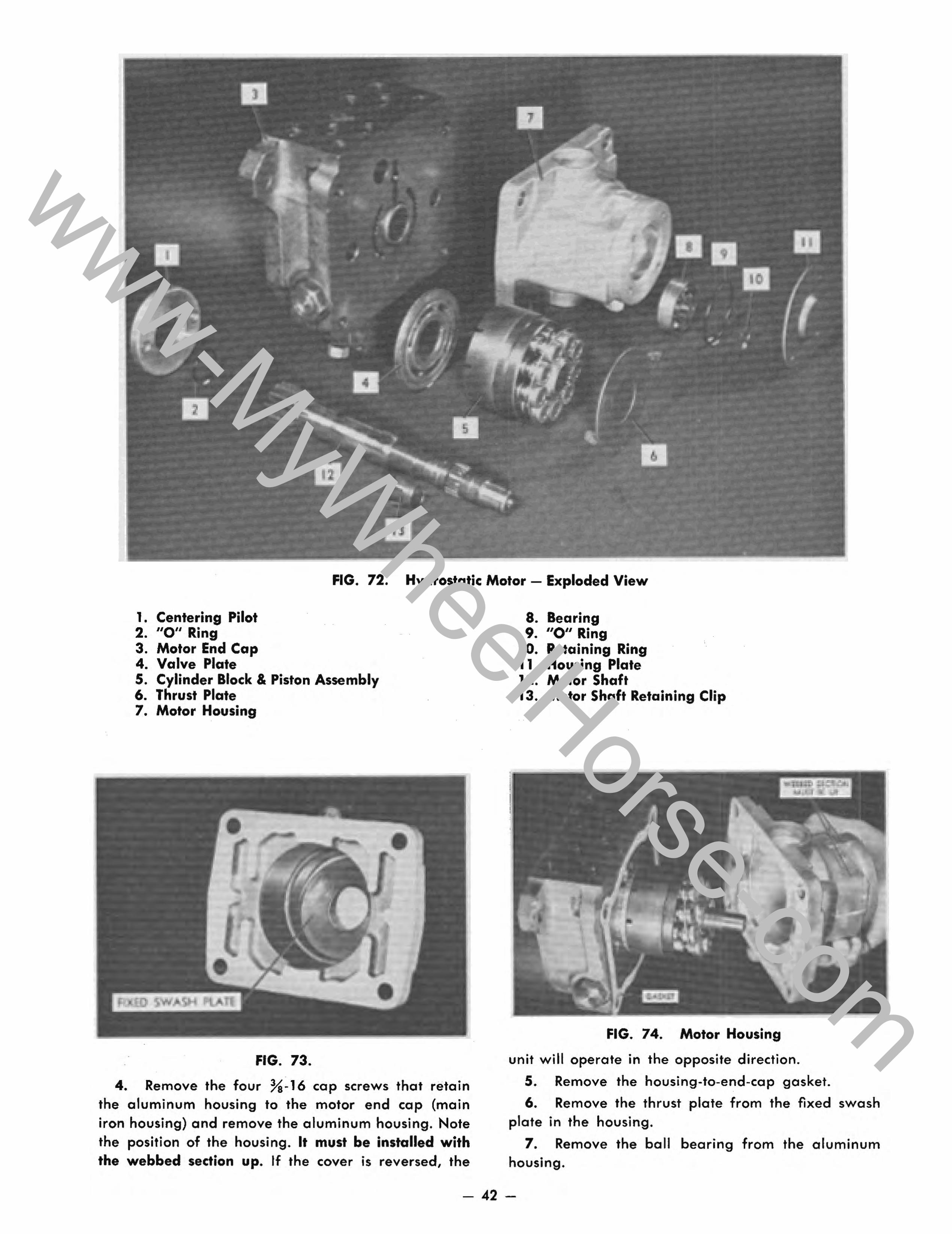
FIG. 72. Hydrostatic Motor - Exploded View
1. Centering Pilot 2. "0" Ring 3. Motor End Cap 4. Valve Plate S. Cylinder Block & Piston Assembly 6. Thrust Plate 7. Motor Housing
FIG. 73.
4. Remove the four Ya-16 cap screws that retain the aluminum housing to the motor end cap (main iron housing) and remove the aluminum housing. Note the position of the housing. It must be installed with the webbed sedion up. If the cover is reversed, the
8. Bearing 9. "0" Ring
10. Retaining Ring 11. Housing Plate 12. Motor Shaft 13. Motor Shaft Retaining Clip
FIG. 74. Motor Housing
unit will operate in the opposite direction.
S. Remove the housing-to-end-cap gasket.
6. Remove the thrust plate from the fixed swash plate in the housing.
7. Remove the ball bearing from the aluminum housing.
- 42-
www-MyWheelHorse-com
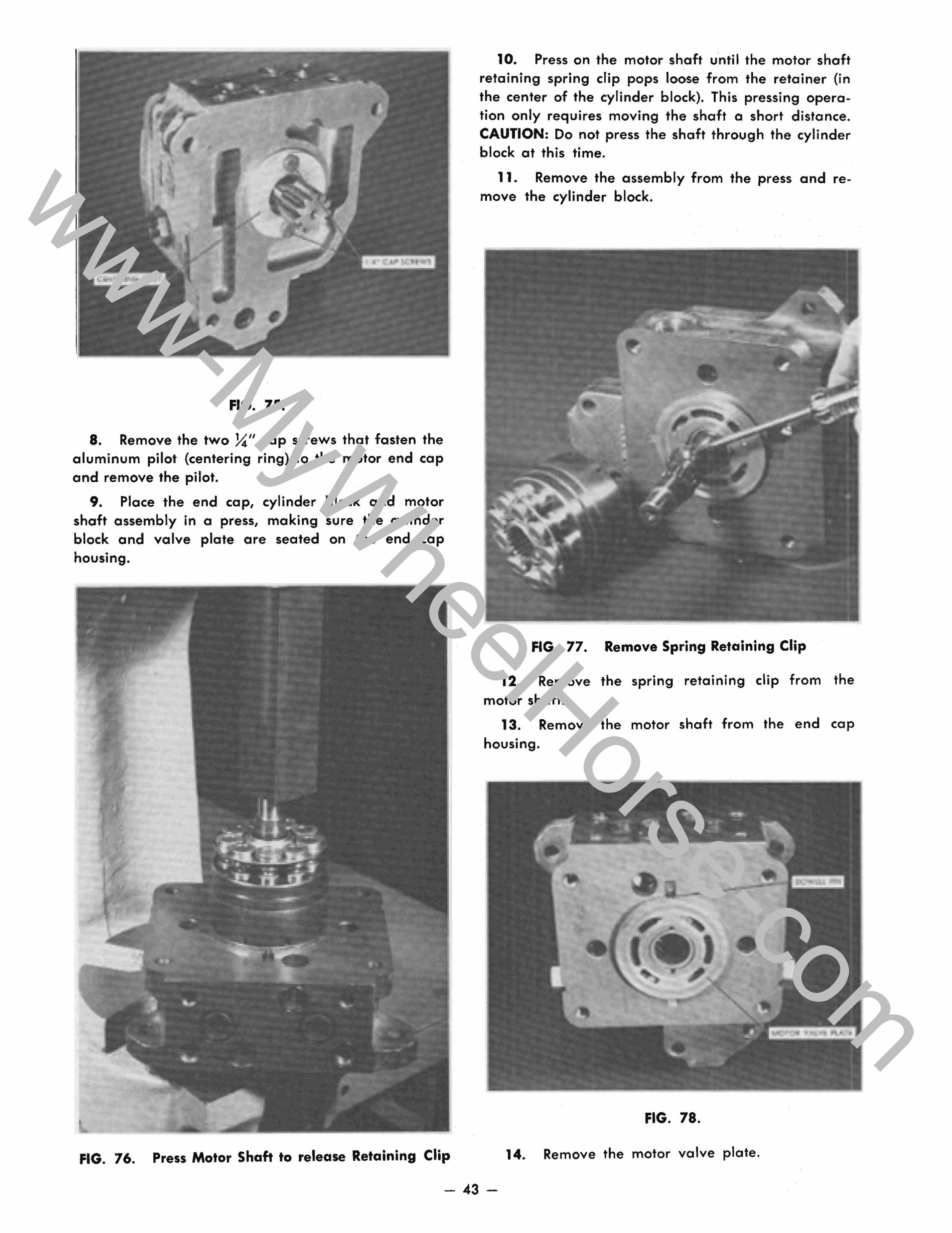
FIG. 75.
8. Remove the two ~" cap screws that fasten the aluminum pilot (centering ring) to the motor end cap and remove the pilot.
9. Place the end cap, cylinder block and motor shaft assembly in a press, making sure the cylinder block and valve plate are seated on the end cap housing.
FIG. 76. Press Motor Shaft to release Retaining Clip
10. Press on the motor shaft until the motor shaft retaining spring clip pops loose from the retainer (in the center of the cylinder block). This pressing operation only requires moving the shaft a short distance. CAUTION: Do not press the shaft through the cylinder block at this time.
11. Remove the assembly from the press and remove the cylinder block.
FIG. 77. Remove Spring Retaining Clip
12. Remove the spring retaining clip from the motor shaft.
13. Remove the motor shaft from the end cap housing.
FIG. 78.
14. Remove the motor valve plate.
- 43-
www-MyWheelHorse-com
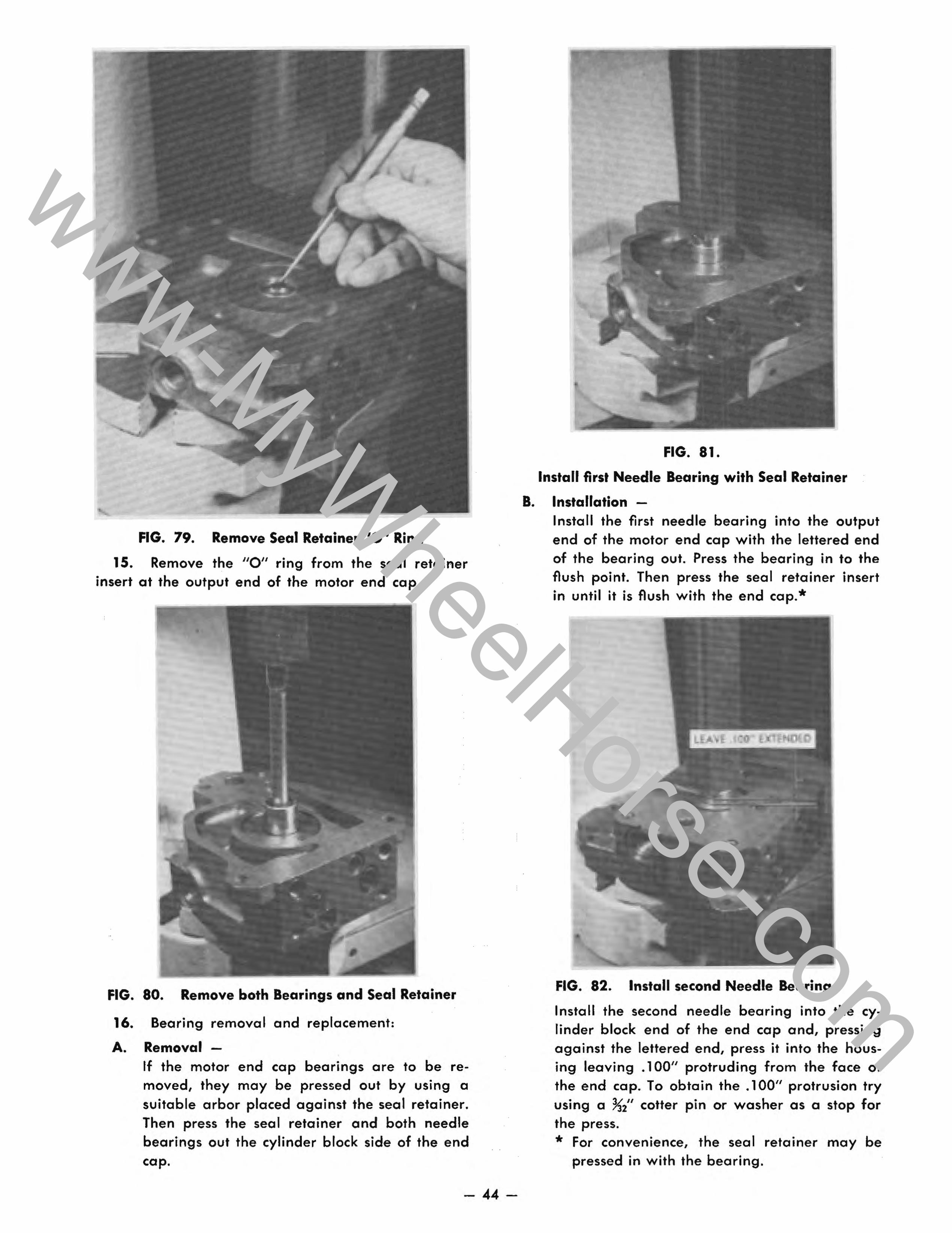
FIG. 79. Remove Seal Retainer "0" Ring
15. Remove the "0" ring from the seal retainer insert at the output end of the motor end cap.
FIG. 80. Remove both Bearings and Seal Retainer
16. Bearing removal and replacement:
A. Removal-If the motor end cap bearings are to be removed, they may be pressed out by using a suitable arbor placed against the seal retainer. Then press the seal retainer and both needle bearings out the cylinder block side of the end cap.
- 44-
B.
FIG. 81.
Install first Needle Bearing with Seal Retainer
Installation -Install the first needle bearing into the output end of the motor end cap with the lettered end of the bearing out. Press the bearing in to the flush point. Then press the seal retainer insert in until it is flush with the end cap. *
FIG. 82. Install second Needle Bearing
Install the second needle bearing into the cylinder block end of the end cap and, pressing against the lettered end, press it into the housing leaving .100" protruding from the face of the end cap. To obtain the .100" protrusion try using a ~2" cotter pin or washer as a stop for the press. * For convenience, the seal retainer may be
pressed in with the bearing.
www-MyWheelHorse-com

Assembly of Motor
1. Install a new "0" ring seal in the recess of the output shaft seal retainer.
2. Install the aluminum centering pilot on the output end of the motor end cap and retain with the two X" cap screws.
FIG. 83.
3. Install the valve plate with the steel side toward the motor end cap, making sure it is centered over the needle bearing and over the end cap dowel pin.
4. Apply 10W30 oil to the bearing surfaces of the shaft and install the motor shaft with the gear at the output end of the motor end cap.
FIG. 84. Spring Retaining Clip
5. Install the motor shaft spring clip with the prongs toward the output gear.
6. Apply 10W30 oil on the va Ive plate surface, the cylinder block valving surface and through the valving ports into the cylinder bores.
FIG. 85. Install Piston-Cylinder Block Assembly
7. Slide the cylinder block, pistons, slippers and slipper retainer assembly on the motor shaft. Push it in place until the spring retaining clip seats.
8. Install the ball bearing in the end of the aluminum housing with lettered end out.
9. Install the four %-16 cap screws through the aluminum housing and install a new gasket over the bolts.
10. Install the thrust plate on the swash plate surface of the housing.
11. With the webbed side of the housing to the top, using the screws as a pilot, install the housing over the shaft and push it in enough to start the screws. Snug up the screws evenly until the housing is approximately ~6" away from the end cap. Do not tighten at this time.
12. Install the bearing retaining ring on the end of the pump shaft.
13. Install the large "0" ring seal in the housing recess around the outside of the bearing.
14. Install the end cover and secure with the four Allen head screws and tighten evenly.
15. Push the housing up flush to seat against the end cap and tighten all four screws evenly.
45 -
www-MyWheelHorse-com
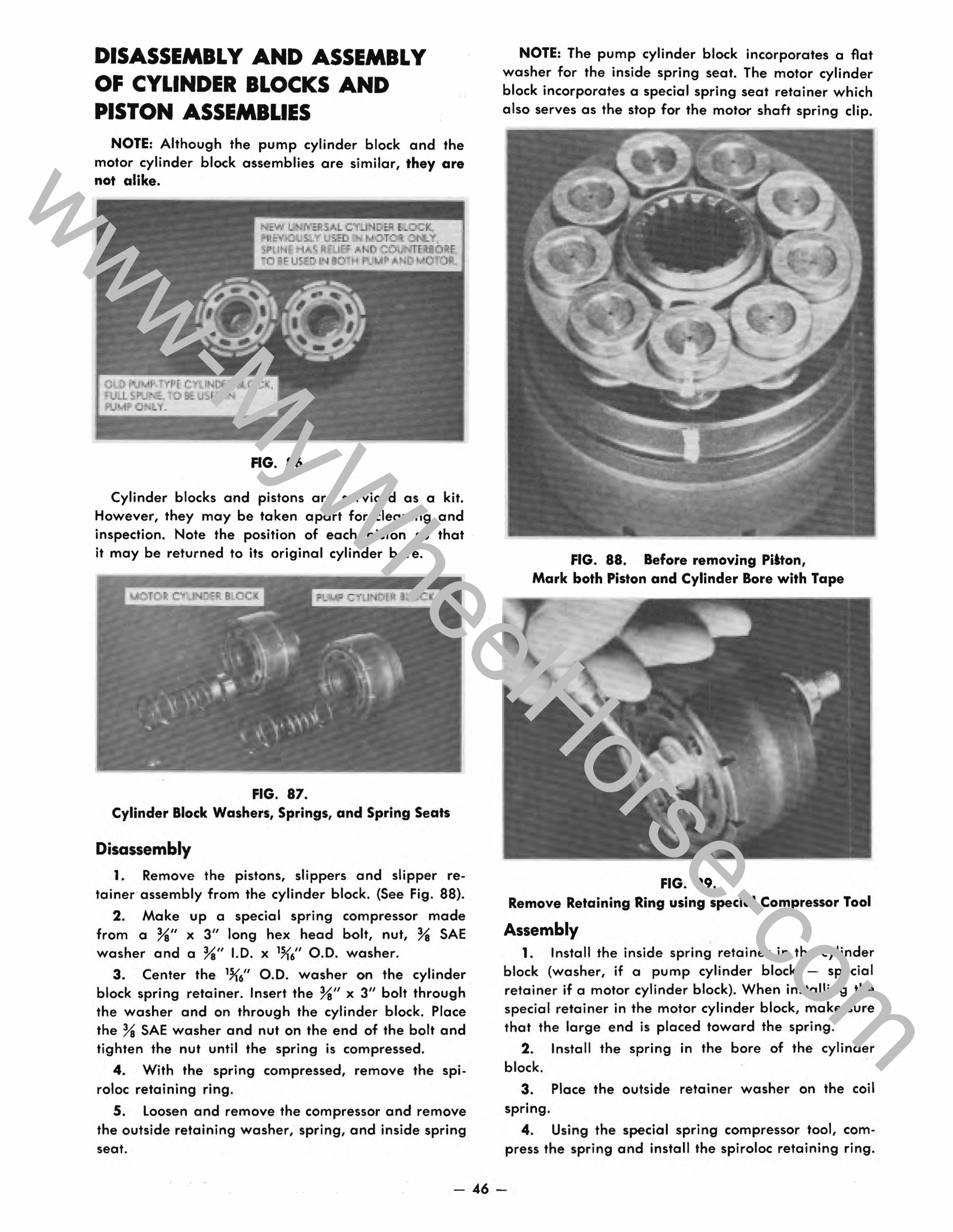
DISASSEMBLY AND ASSEMBLY OF CYLINDER BLOCKS AND PISTON ASSEMBLIES
NOTE: Although the pump cylinder block and the motor cylinder block assemblies are similar, they are not alike.
FIG. 86.
Cylinder blocks and pistons are serviced as a kit. However, they may be taken apart for cleaning and inspection. Note the position of each piston so that it may be returned to its original cylinder bore.
FIG. 87. Cylinder Block Washers, Springs, and Spring Seats
Disassembly
1. Remove the pistons, slippers and slipper retainer assembly from the cylinder block. (See Fig. 88).
2. Make up a special spring compressor made from a %" x 3" long hex head bolt, nut, % SAE washer and a %" 1.0. x 1~6" 0.0. washer.
3. Center the 1~6" 0.0. washer on the cylinder block spring retainer. Insert the %" x 3" bolt through the washer and on through the cylinder block. Place the % SAE washer and nut on the end of the bolt and tighten the nut until the spring is compressed.
4. With the spring compressed, remove the spiroloc retaining ring.
5. Loosen and remove the compressor and remove the outside retaining washer, spring, and inside spring seat.
NOTE: The pump cylinder block incorporates a flat washer for the inside spring seat. The motor cylinder block incorporates a special spring seat retainer which also serves as the stop for the motor shaft spring clip.
FIG. 88. Before removing Pitton, Mark both Piston and Cylinder Bore with Tape
FIG. 89. Remove Retaining Ring using special Compressor Tool
Assembly .
1. Install the inside spring retainer in the cylinder block (washer, if a pump cylinder block - special retainer if a motor cylinder block). When installing the special retainer in the motor cylinder block, make sure that the large end is placed toward the spring.
2. Install the spring in the bore of the cylinder block.
3. Place the outside retainer washer on the coil • spring.
4. Using the special spring compressor tool, compress the spring and install the spiroloc retaining ring.
- 46-
www-MyWheelHorse-com
HYDROGEAR
SECTION
- 47-
www-MyWheelHorse-com
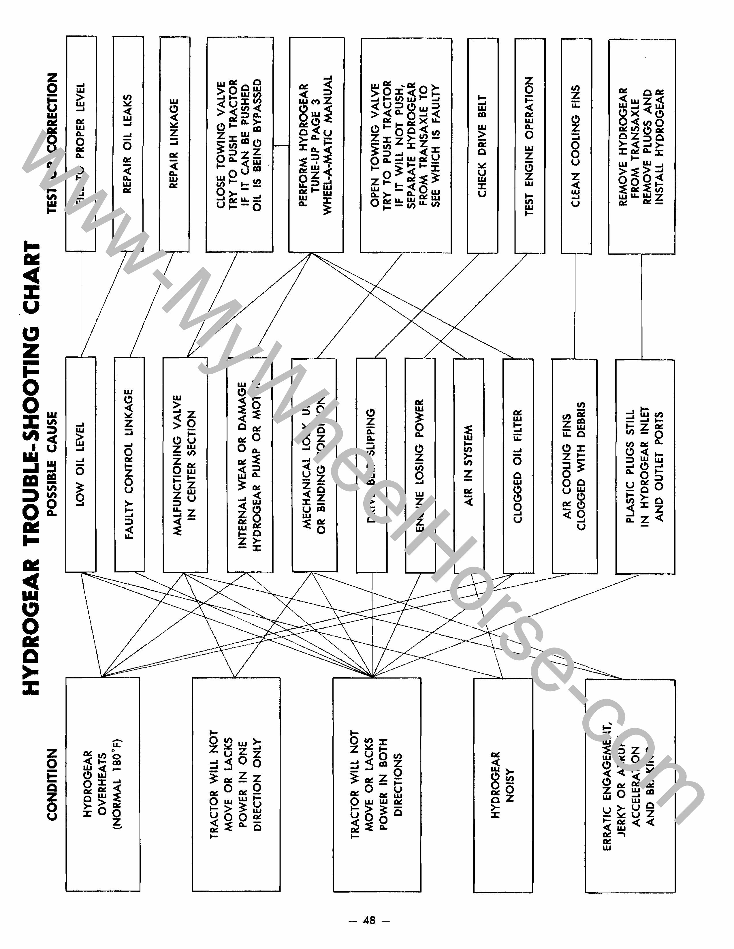
I .a... 00
I
CONDITION
HYDROGEAR OVERHEATS
(NORMAL lBO'F)
,
TRACTOR WILL NOT MOVE OR LACKS POWER IN ONE
DIRECTION ONLY
TRACTOR WILL NOT MOVE OR LACKS POWER IN BOTH
DIRECTIONS
HYDROGEAR NOISY
ERRATIC ENGAGEMENT, JERKY OR ABRUPT
ACCELERATION AND BRAKING
.
HYDROGEAR TROUBLE-SHOOTING CHART POSSIBLE CAUSE
_______ ) LOW OIL LEVEL I
v
" ~
I
.~
FAULTY CONTROL LINKAGE
MALFUNCTIONING VALVE IN CENTER SECTION
INTERNAL WEAR OR DAMAGE HYDROGEAR PUMP OR MOTOR
MECHANICAL LOCK UP OR BINDING CONDITION
DRIVE BELT SLIPPING
ENGINE LOSING POWER
AIR IN SYSTEM
~I I CLOGGED OIL FILTER
AIR COOLING FINS I CLOGGED WITH DEBRIS J
PLASTIC PLUGS STILL IN HYDROGEAR INLET AND OUTLET PORTS
I
'-....
1
TEST OR CORRECTION
FILL TO PROPER LEVEL
REPAIR OIL LEAKS
REPAIR LINKAGE
CLOSE TOWING VALVE TRY TO PUSH TRACTOR IF IT CAN BE PUSHED
OIL IS BEING BYPASSED
PERFORM HYDROGEAR TUNE-UP PAGE 3
WHEEL-A-MATIC MANUAL
OPEN TOWING VALVE TRY TO PUSH TRACTOR IF IT WILL NOT PUSH, SEPARATE HYDROGEAR FROM TRANSAXLE TO SEE WHICH IS FAULTY
CHECK DRIVE BELT
TEST ENGINE OPERATION
CLEAN COOLING FINS
REMOVE HYDROGEAR FROM TRANSAXLE
REMOVE PLUGS AND INSTALL HYDROGEAR
www-MyWheelHorse-com
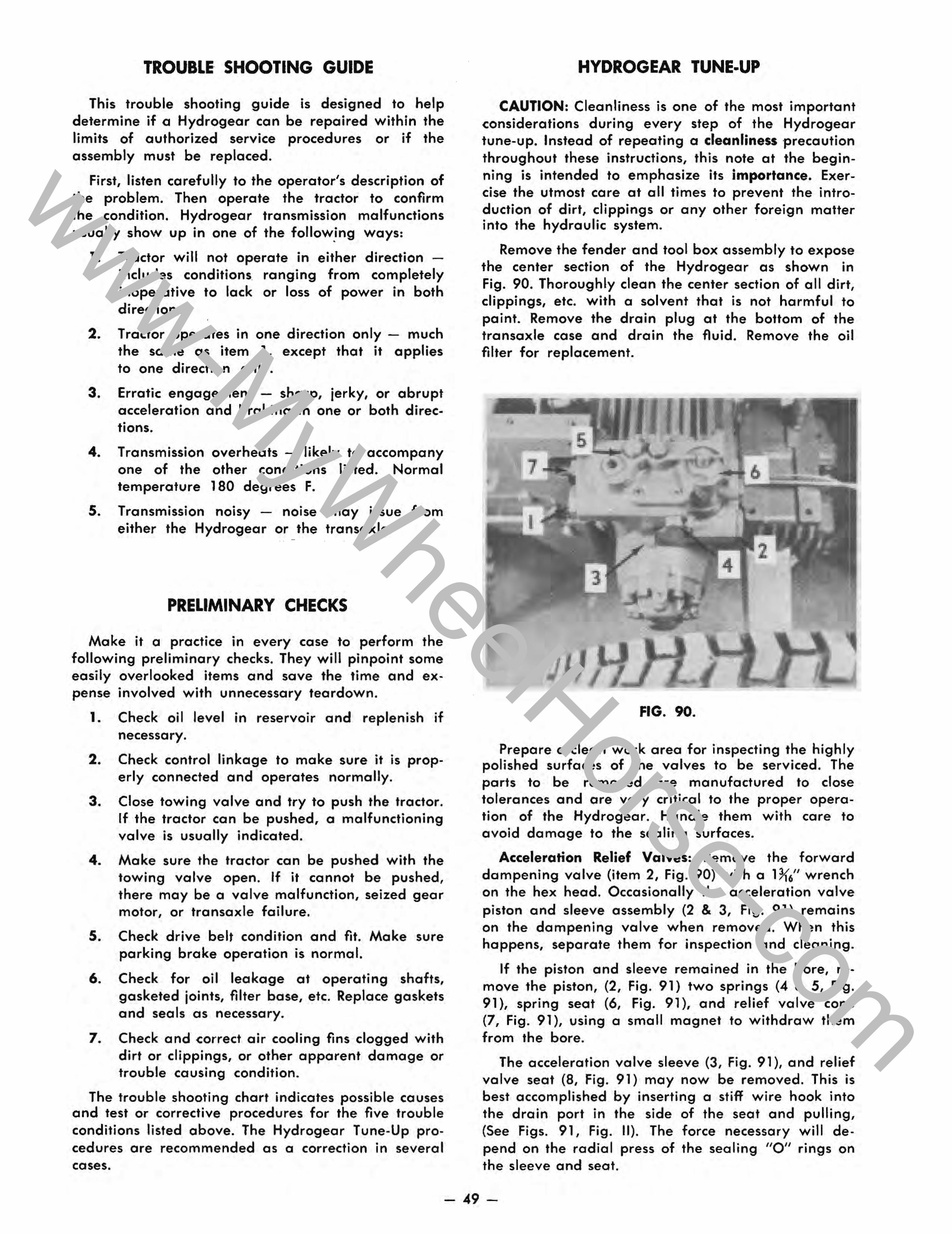
TROUBLf SHOOTING GUIDE
This trouble shooting guide is designed to help determine if a Hydrogear can be repaired within the limits of authorized service procedures or if the assembly must be replaced.
First, listen carefully to the operator's description of the problem. Then operate the tractor to confirm the condition. Hydrogear transmission malfunctions usually show up in one of the follow,ing ways:
1. Tractor will not operate in either direction -includes conditions ranging from completely inoperative to lack or loss of power in both directions.
2. Tractor operates in one direction only - much the same as item 1, except that it applies to one direction only.
3. Erratic engagement - sharp, jerky, or abrupt acceleration and braking in one or both direc-
• tlons.
4. Transmission overheats - likely to accompany one of the other conditions listed. Normal temperature 180 degrees F.
s. Transmission noisy - noise either the Hydrogear or the
• may Issue transaxle.
PRELIMINARY CHECKS
from
Make it a practice in every case to perform the following preliminary checks. They will pinpoint some easily overlooked items and save the time and expense involved with unnecessary teardown.
1. Check oil level in reservoir and replenish if necessary.
2. Check control linkage to make sure it is properly connected and operates normally.
3. Close towing valve and try to push the tractor. If the tractor can be pushed, a malfunctioning valve is usually indicated.
4. Make sure the tractor can be pushed with the towing valve open. If it cannot be pushed, there may be a valve malfunction, seized gear motor, or transaxle failure.
S. Check drive belt condition and fit. Make sure parking brake operation is normal.
6. Check for oil leakage at operating shafts, gasketed joints, filter base, etc. Replace gaskets and seals as necessary.
7. Check and correct air cooling fins clogged with dirt or clippings, or other apparent damage or trouble causing condition.
The trouble shooting chart indicates possible causes and test or corrective procedures for the five trouble conditions listed above. The Hydrogear Tune-Up procedures are recommended as a correction in several cases.
HYDROGEAR TUNE-UP
CAUTION: Cleanliness is one of the most important considerations during every step of the Hydrogear tune-up. Instead of repeating a cleanliness precaution throughout these instructions, this note at the beginning is intended to emphasize its importance. exercise the utmost care at all times to prevent the introduction of dirt, clippings or any other foreign matter into the hydraulic system.
Remove the fender and tool box assembly to expose the center section of the Hydrogear as shown in Fig. 90. Thoroughly clean the center section of all dirt, clippings, etc. with a solvent that is not harmful to paint. Remove the drain plug at the bottom of the transaxle case and drain the fluid. Remove the oil filter for replacement.
FIG. 90.
Prepare a clean work area for inspecting the highly polished surfaces of the valves to be serviced. The parts to be removed are manufactured to close tolerances and are very critical to the proper operation of the Hydrogear. Handle them with care to avoid damage to the sealing surfaces.
Acceleration Relief Valves: Remove the forward dampening valve (item 2, Fig. 90) with a H(6" wrench on the hex head. Occasionally the acceleration valve piston and sleeve assembly (2 & 3, Fig. 91) remains on the dampening valve when removed. When this happens, separate them for inspection and cleaning.
If the piston and sleeve remained in the bore, remove the piston, (2, Fig. 91) two springs (4 & 5, Fig. 91), spring seat (6, Fig. 91), and relief valve cone (7, Fig. 91), using a small magnet to withdraw them from the bore.
The acceleration valve sleeve (3, Fig. 91), and relief valve seat (8, Fig. 91) may now be removed. This is best accomplished by inserting a stiff wire hook into the drain port in the side of the seat and pulling, (See Figs. 91, Fig. II). The force necessary will depend on the radial press of the sealing "0" rings on the sleeve and seat.
- 49-
www-MyWheelHorse-com
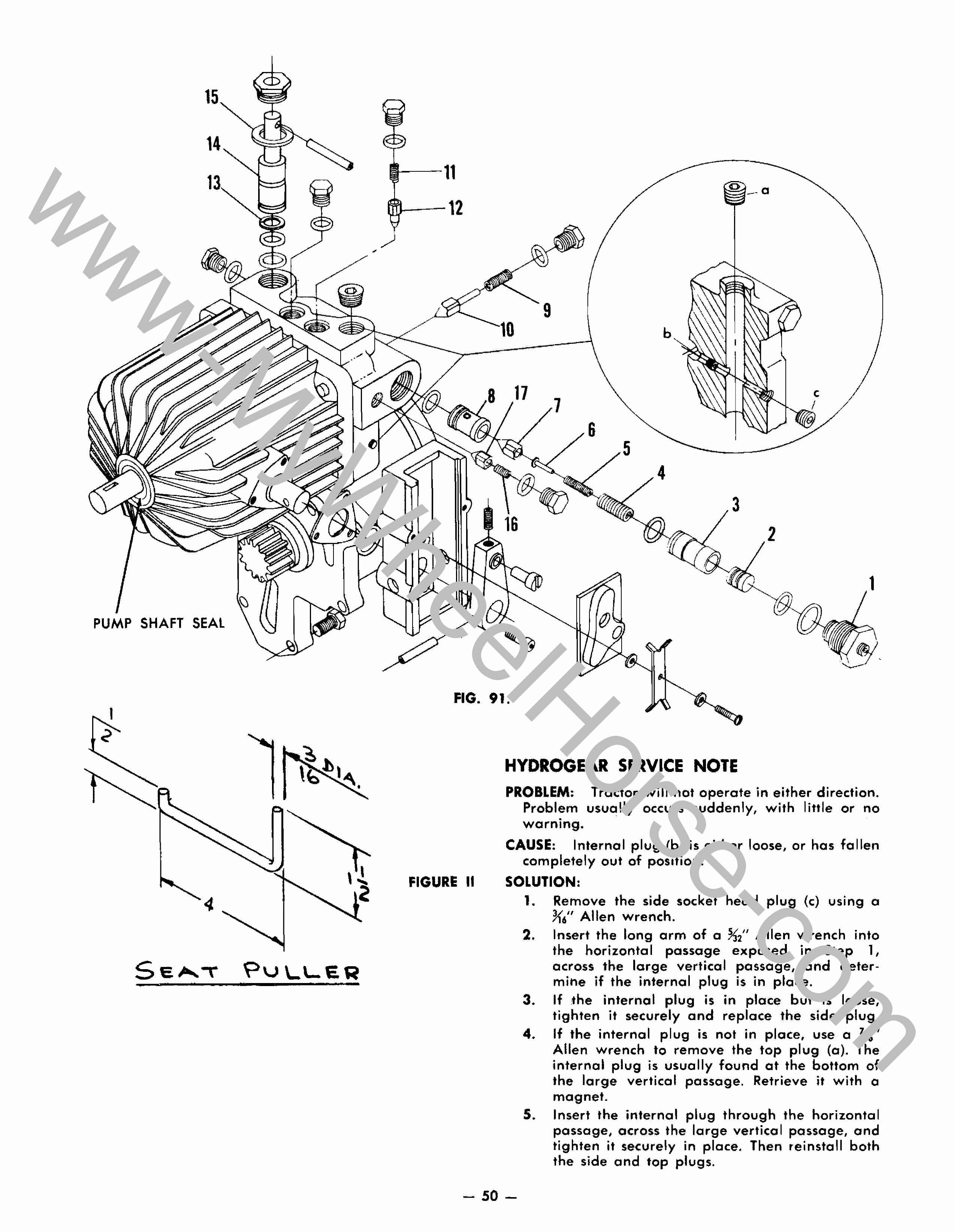
15
14
PUMP SHAFT SEAL
\ ' '2
Se,-..."" l=>\.)L'-E~ • = • T T
--11
~-12
16 3
a
1
FIG. 91.
FIGURE II
HYDROGEAR SERVICE NOTE PROBLEM: Tractor will not operate in either direction.
Problem usually occurs suddenly, with little or no • warning.
CAUSE: Internal plug (b) is either loose, or has fallen completely out of position.
SOLUTION: 1. Remove the side socket head plug (c) using a
7<," Allen wrench. 2. Insert the long arm of a %2" Allen wrench into
the horizontal passage exposed in Step 1, across the large vertical passage, and determine if the internal plug is in place.
3. If the internal plug is in place but is loose, tighten it securely and replace the side plug.
4. If the internal plug is not in place, use a K6" Allen wrench to remove the top plug (a). The internal plug is usually found at the bottom of the large vertical passage. Retrieve it with a magnet.
5. Insert the internal plug through the horizontal passage, across the large vertical passage, and tighten it securely in place. Then reinstall both the side and top plugs.
- 50-
www-MyWheelHorse-com
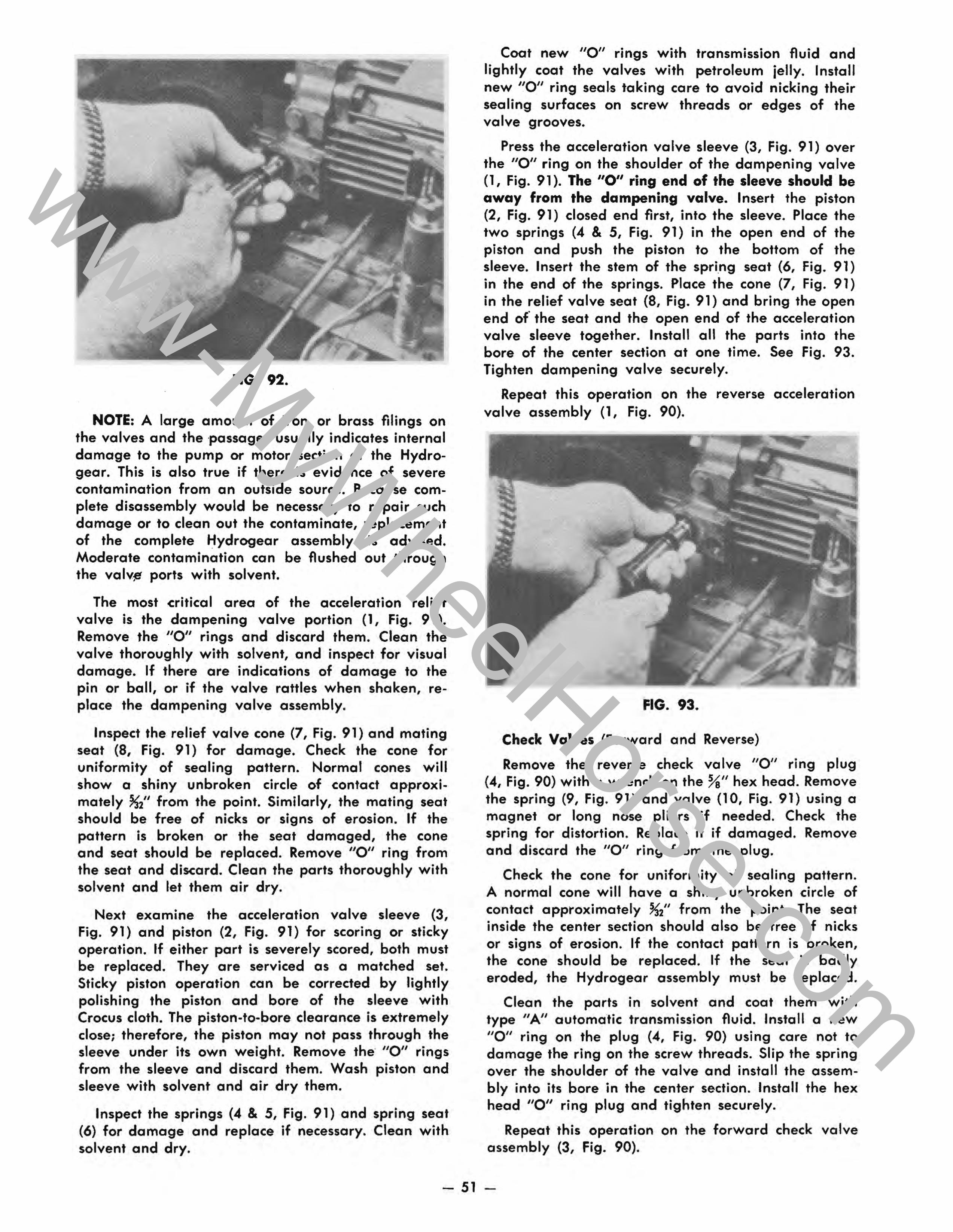
FIG. 92.
NOTE: A large amount of iron or brass filings on the valves and the 'passages usually indicates internal damage to the pump or motor section of the Hydrogear. This is also true if there is evidence of severe contamination from an outside source. Because complete disassembly would be necessary to repair such damage or to clean out the contaminate, replacement of the complete Hydrogear assembly is advised. Moderate contamination can be flushed out through the valv~ ports with solvent.
The most critical area of the acceleration relief valve is the dampening valve portion (1, Fig. 91). Remove the "0" rings and discard them. Clean the valve thoroughly with solvent, and inspect for visual damage. If there are indications of damage to the pin or ball, or if the valve rattles when shaken, replace the dampening valve assembly.
Inspect the relief valve cone (7, Fig. 91) and mating seat (8, Fig. 91) for damage. Check the cone for uniformity of sealing pattern. Normal cones will show a shiny unbroken circle of contact approximately %2" from the point. Similarly, the mating seat should be free of nicks or signs of erosion. If the pattern is broken or the seat damaged, the cone and seat should be replaced. Remove "0" ring from the seat and discard. Clean the parts thoroughly with solvent and let them air dry.
Next examine the acceleration valve sleeve (3, Fig. 91) and piston (2, Fig. 91) for scoring or sticky operation. If either part is severely scored, both must be replaced. They are serviced as a matched set. Sticky piston operation can be corrected by lightly polishing the piston and bore of the sleeve with Crocus cloth. The piston-to-bore clearance is extremely close; therefore, the piston may not pass through the sleeve under its own weight. Remove the "0" rings from the sleeve and discard them. Wash piston and sleeve with solvent and air dry them.
Inspect the springs (4 & 5, Fig. 91) and (6) for damage and replace if necessary. solvent and dry.
• spring seat Clean with
Coat new "0" rings with transmission fluid and lightly coat the valves with petroleum jelly. Install new "0" ring seal·s taking care to avoid nicking their sealing surfaces on screw threads or edges of the valve grooves.
Press the acceleration valve sleeve (3, Fig. 91) over the "0" ring on the shoulder of the dampening valve (1, Fig. 91). The "0" ring end of the sleeve should be away from the dampening valve. Insert the piston (2, Fig. 91) closed end first, into the sleeve. Place the two springs (4 & 5, Fig. 91) in the open end of the piston and push the piston to the bottom of the sleeve. Insert the stem of the spring seat (6, Fig. 91) in the end of the springs. Place the cone (7, Fig. 91) in the relief valve seat (8, Fig. 91) and bring the open end of' the seat and the open end of the acceleration valve sleeve together. Install all the parts into the bore of the center section at one time. See Fig. 93. Tighten dampening valve securely.
Repeat this operation on the reverse acceleration valve assembly (1, Fig. 90).
FIG. 93.
Check Valves (Forward and Reverse)
Remove the reverse check valve "0" ring plug (4, Fig. 90) with a wrench on the %" hex head. Remove the spring (9, Fig. 91) and valve (10, Fig. 91) using a magnet or long nose pliers if needed. Check the spring for distortion. Replace it if damaged. Remove and discard the "0" ring from the plug.
Check the cone for uniformity of sealing pattern. A normal cone will have a shiny unbroken circle of contact approximately ~2" from the point. The seat inside the center section should also be free of nicks or signs of erosion. If the contact pattern is broken, the cone should be replaced. If the seat is badly eroded, the Hydrogear assembly must be replaced.
Clean the parts in solvent and coat them with type "A" automatic transmission fluid. Install a new "0" ring on the plug (4, Fig. 90) using care not to damage the ring on the screw threads. Slip the spring over the shoulder of the valve and install the assembly into its bore in the center section. Install the hex head "0" ring plug and tighten securely.
Repeat this operation on the forward check valve assembly (3, fig. 90).
- 51 -
www-MyWheelHorse-com
Charge Relief Valve
Remove the %" hex head "0" ring plug (5, Fig. 90). Remove the spring (11, Fig. 91) and valve (12, Fig. 91) using a magnet to withdraw them from the bore.
NOTE: There may be shims inside the plug to control valve spring tension. Take care not to lose them.
Remove and discard the "Oil ring from the plug. Check the spring for distortion. Replace if damaged. Check the nose of the valve for continuous sealing pattern and replace it if damaged. Check the seat in the center section for nicks or signs of erosion. If it is badly eroded, the Hydrogear assembly must be replaced.
Clean the parts with solvent and coat them with type II A" automatic transmission fluid. Install a new "0" ring on the plug (5, Fig. 90) using care not to damage it on the screw threads. Install the spring in the valve and insert the assembly, valve first, into its bore on top of the center section. Install the hex head "0" ring plug and tighten securely.
Towing Valv-e (If applicable)
Back out the 1" hex shoulder plug (6, Fig. 90). Pull the valve assembly (14, Fig. 91) out of the bore. The force required will depend on the radial press of the sealing rings on the barrel of the valve.
Remove and discard the "0" rings and the Teflon back up ring (13, Fig. 91). Clean the valve with solvent, dry, and coat with type "A" automatic transmission fluid. Install the Teflon back up ring (13, Fig. 91) in the top groove of the valve. Install an "0" ring alongside the back up ring in the same groove on the side away from the valve stem. Install the second "0" ring in the bottom groove. From top to bottom of the valve, the rings stack up in this order: Teflon ring, "0" ring, "0" ring.
Place the washer (15, Fig. 91) around the bore in the center section and, with a twisting motion, insert the valve into the bore. Start the hex shoulder plug threads and rotate the valve while drawing it into place with the plug. Tighten the plug securely.
Implement Relief Valve (If so equipped)
Remove the %" hex head "0" ring plug (7, Fig. 90). Remove the spring (16, Fig. 91) and valve (17, Fig. 91) using a magnet to withdraw them from the bore. Remove and discord the /'0" ring from the plug. Check the spring for distortion. Replace if damaged.
Check the nose of the valve for continuous sealing pattern and replace if damaged. Check the seat in the center section for nicks or signs of erosion. If it is badly eroded, the Hydrogear assembly must be replaced.
Clean the parts with solvent and coat them with type "A" automatic transmission fluid. Install a new "0" ring on the plug (7, Fig. 90) using care not to damage it on the screw threads. Insert the spring in the valve and install the assembly, valve first, into its bore on the front of the center section. Install the hex head "0" ring plug and tighten securely.
Install new oil filter. Install the drain plug in the bottom of the transaxle. Fill to proper level with type "A' automatic transmission fluid. Approximately four quarts will be required.
Block the tractor up with the rear wheels off the ground. Run the engine at low speed and operate the Hydrogear in forward and reverse to circulate fluid through the system and to check for leaks. Recheck the fluid level and add as necessary.
Adjust neutral position. lower rear wheels to the ground. Reinstall the fender and tool box assembly.
Run the tractor to thoroughly test operation of the Hydrogear.
HYDROGEAR
REMOVAL AND REPLACEMENT
Removal
If the transmission has been contaminated either with metal filings or other foreign matter, the fluid must be changed and the oil filter replaced. The transaxle must also be flushed thoroughly before a new Hydrogear assembly is installed.
Support rear of tractor with rear wheels off the floor. Remove the left rear wheel. If tractor has tail light, disconnect wire and bring it forward of the tool box. If the tractor has a hydraulic lift, disconnect the hoses from the Hydrogear and move them forward out of the way. Remove the instruction plate (located in front of the seat) by removing four mount-• Ing screws.
Remove the four tool box to transmission bolts and remove the fender, seat and tool box as an assembly.
NOTE: On 1965, 1966 and 1967 models it is also necessary to remove the fan guard. The 1968 and 1969 models will also require the removal of the two belt guard-to-otool box bolts.
Remove the belt guard and drive belt. To do this on 1968 and 1969 models, the R.H. foot rest must be removed. Remove the cooling fan from the drive pulley, if so equipped, and remove the pulley.
Clean all dirt and clippings off the Hydrogear and surrounding area with solvent and compressed air to keep the interior of the transaxle free of foreign matter when the Hydrogear is separated from the transaxle.
Place a drain pan beneath the Hydrogear.
- 52-
www-MyWheelHorse-com
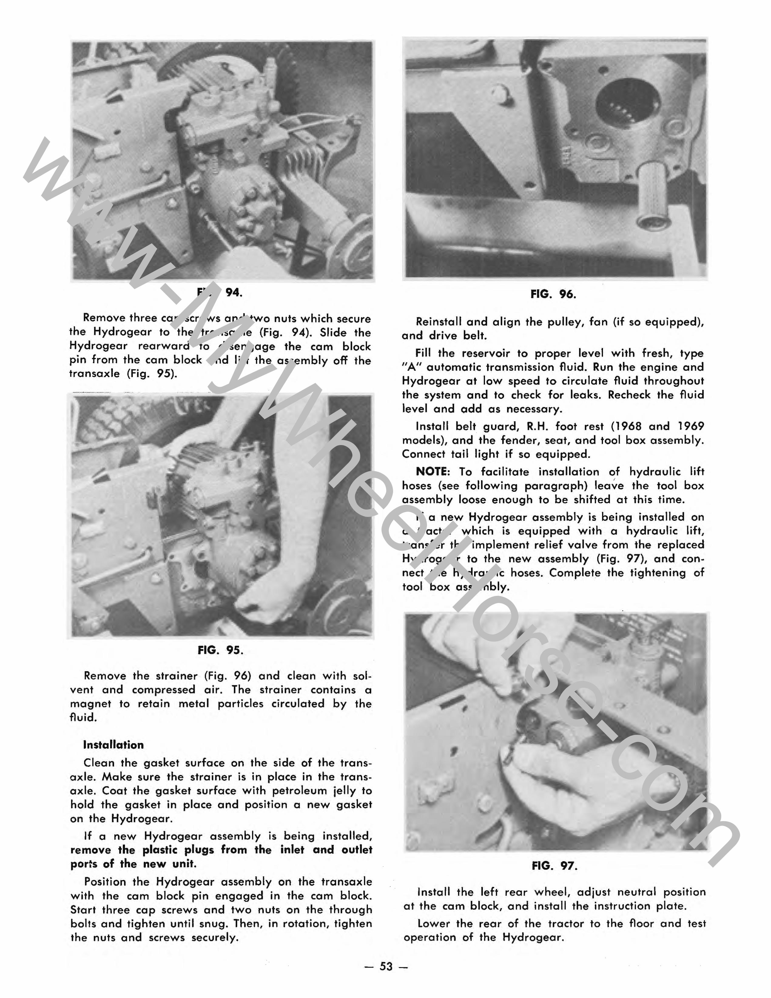
FIG. 94.
Remove three cap screws and two nuts which secure the Hydrogear to the transaxle (Fig. 94). Slide the Hydrogear rearward to disengage the cam block pin from the cam block and lift the assembly off the transaxle (Fig. 95).
FIG. 95.
Remove the strainer (Fig. 96) and clean with solvent and compressed air. The strainer contains a magnet to retain metal particles circulated by the fluid.
Installation
Clean the gasket surface on the side of the transaxle. Make sure the strainer is in place in the transaxle. Coat the gasket surface with petroleum jelly to hold the gasket in place and position a new gasket on the Hydrogear.
If a new Hydrogear assembly is being installed, remove the plastic plugs from the inlet and outlet ports of the new unit.
Position the Hydrogear assembly on the transaxle with the cam block pin engaged in the cam block. Start three cap screws and two nuts on the through bolts and tighten until snug. Then, in rotation, tighten the nuts and screws securely.
FIG. 96.
Reinstall and align the pulley, fan (if so equipped), and drive belt.
Fill the reservoir to proper level with fresh, type "A" automatic transmission fluid. Run the engine and Hydrogear at low speed to circulate fluid throughout the system and to check for leaks. Recheck the fluid level and add as necessary.
Install belt guard, R.H. foot rest (1968 and 1969 models), and the fender, seat, and tool box assembly. Connect tail light if so equipped.
NOTE: To facilitate installation of hydraulic lift , hoses (see following paragraph) leave the tool box assembly loose enough to be shifted at this time.
If a new Hydrogear assembly is being installed on a tractor which is equipped with a hydraulic lift, transfer the implement relief valve from the replaced Hydrogear to the new assembly (Fig. 97), and connect the hydraulic hoses. Complete the tightening of tool box assembly.
FIG. 97.
Install the left rear wheel, adjust neutral position at the cam block, and install the instruction plate.
lower the rear of the tractor to the floor and test operation of the Hydrogear.
- 53-
www-MyWheelHorse-com
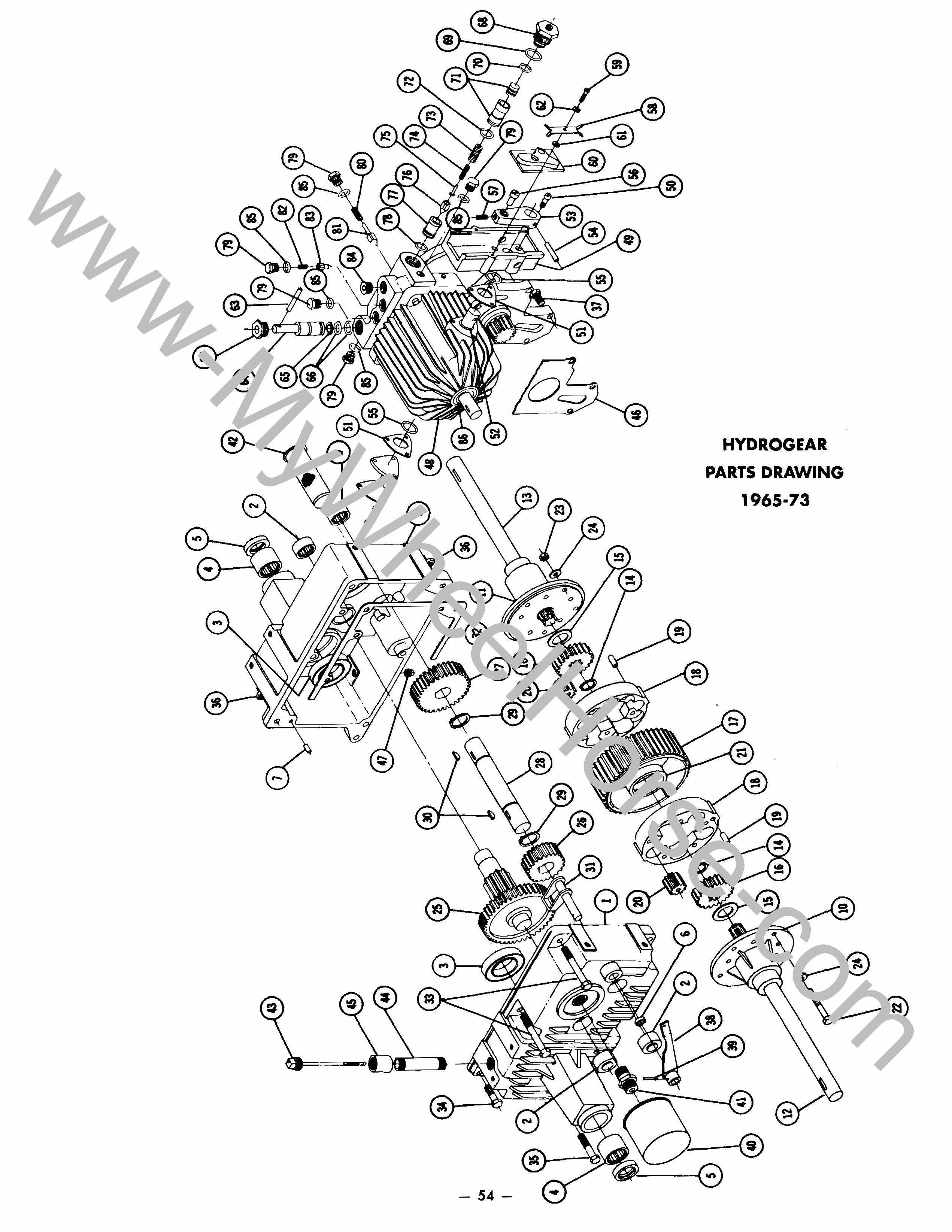
I 1.11 ~
I
4 -35 --
5 -
34 -'
40 41 ......
39 --......
12 )
43
45
3 25 ...... -
1 -zo ......
38 ......
/' )( !V
10) 24
~ "-
ZZ
3 4 -36 ....... -
7 -
47
11 32 ....... -29,_ zo
28 ..... 29 --
31 26
.....
19 18 --......
~~~ , 16 ® .
5 - 67 .....
2
42 ..... 63 79 . • _85 64 .......
65) ''IN IV ..182. .:79 83\\85 ., ........
/::'\ 51) -
./
~"'@l/ / '84
~~~~ 80
48
69 36 86}- ---- .......
52 68 --.......
62 23 ..... 'QY'
54
53 .... 24 ~ ~dA 60 .... -- --
56 61
46 49 ....... .... .... 58 ........ '--
50 ........
~ _ ~ l: I() en ~ 0. tJ ;;a ~ :a 0 "of ~ Q Co) 1ft - » z ;;a
Q
www-MyWheelHorse-com
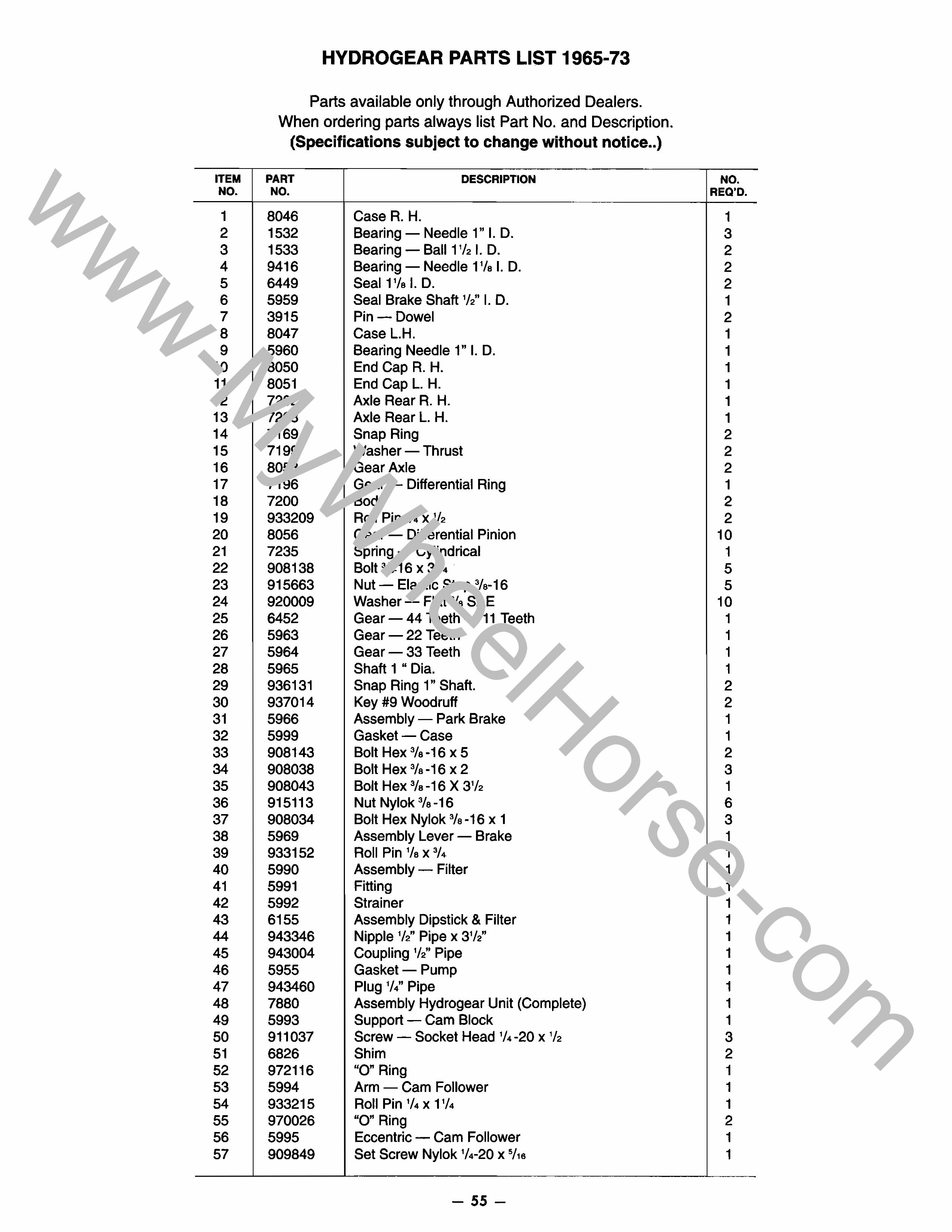
ITEM NO.
1 2 3 4 5 6 7 8 9
10 11 12 13 14 15 16 17 18 19 20 21 22 23 24 25 26 27 28 29 30 31 32 33 34 35 36 37 38 39 40 41 42 43 44 45 46 47 48 49 50 51 52 53 54 55 56 57
HYDROGEAR PARTS LIST 1965-73
Parts available only through Authorized Dealers. When ordering parts always list Part No. and Description.
(Specifications subject to change without notice .. )
PART DESCRIPTION NO.
-
8046 Case R. H. 1532 Bearing - Needle 1" I. D. 1533 Bearing - Ball 1'/2 I. D. 9416 Bearing - Needle 1'/a I. D. 6449 Seal 1'/a I. D. 5959 Seal Brake Shaft '12" I. D. 3915 Pin- Dowel 8047 Case L.H. 5960 Bearing Needle 1" I. D. 8050 End Cap R. H. 8051 End Cap L. H. 7202 Axle Rear R. H. 7203 Axle Rear L. H. 7169 Snap Ring 7199 Washer - Thrust 8053 Gear Axle 7196 Gear - Differential Ring 7200 Body 933209 Roll Pin '/4 x '/2 8056 Gear - Differential Pinion 7235 Spring - Cylindrical 908138 Bolt 3/8-16 x 3'/4 . 915663 Nut - Elastic Stop 3/a-16 920009 Washer - Flat 3/a SAE 6452 Gear - 44 Teeth - 11 Teeth 5963 Gear - 22 Teeth 5964 Gear - 33 Teeth 5965 Shaft 1 " Dia. 936131 Snap Ring 1" Shaft. 937014 Key #9 Woodruff 5966 Assembly - Park Brake 5999 Gasket - Case 908143 Bolt Hex 3/a-16 X 5 908038 Bolt Hex 3/a-16 X 2 908043 Bolt Hex 3/a -16 X 3'/2 915113 Nut Nylok 3/a -16 908034 Bolt Hex Nylok 3/a -16 x 1 5969 Assembly Lever - Brake 933152 Roll Pin '/a x 3/4 5990 Assembly - Filter 5991 Fitting 5992 Strainer 6155 Assembly Dipstick & Filter 943346 Nipple '12" Pipe x 3'12" 943004 Coupling '12" Pipe 5955 Gasket - Pump 943460 Plug '14" Pipe 7880 Assembly Hydrogear Unit (Complete) 5993 Support - Cam Block 911037 Screw - Socket Head '/4-20 x '/2 6826 Shim 972116 "0" Ring 5994 Arm - Cam Follower 933215 Roll Pin '/4 x 1'/4 970026 "0" Ring 5995 Eccentric - Cam Follower 909849 Set Screw Nylok '/4-20 x 5/'6
- 55-
NO. REO 'D.
1 3 2 2 2 1 2 1 1 1 1 1 1 2 2 2 1 2 2
10 1 5 5
10 1 1 1 1 2 2 1 1 2 3 1 6 3 1 1 1 1 1 1 1 1 1 1 1 1 3 2 1 1 1 2 1 1
www-MyWheelHorse-com
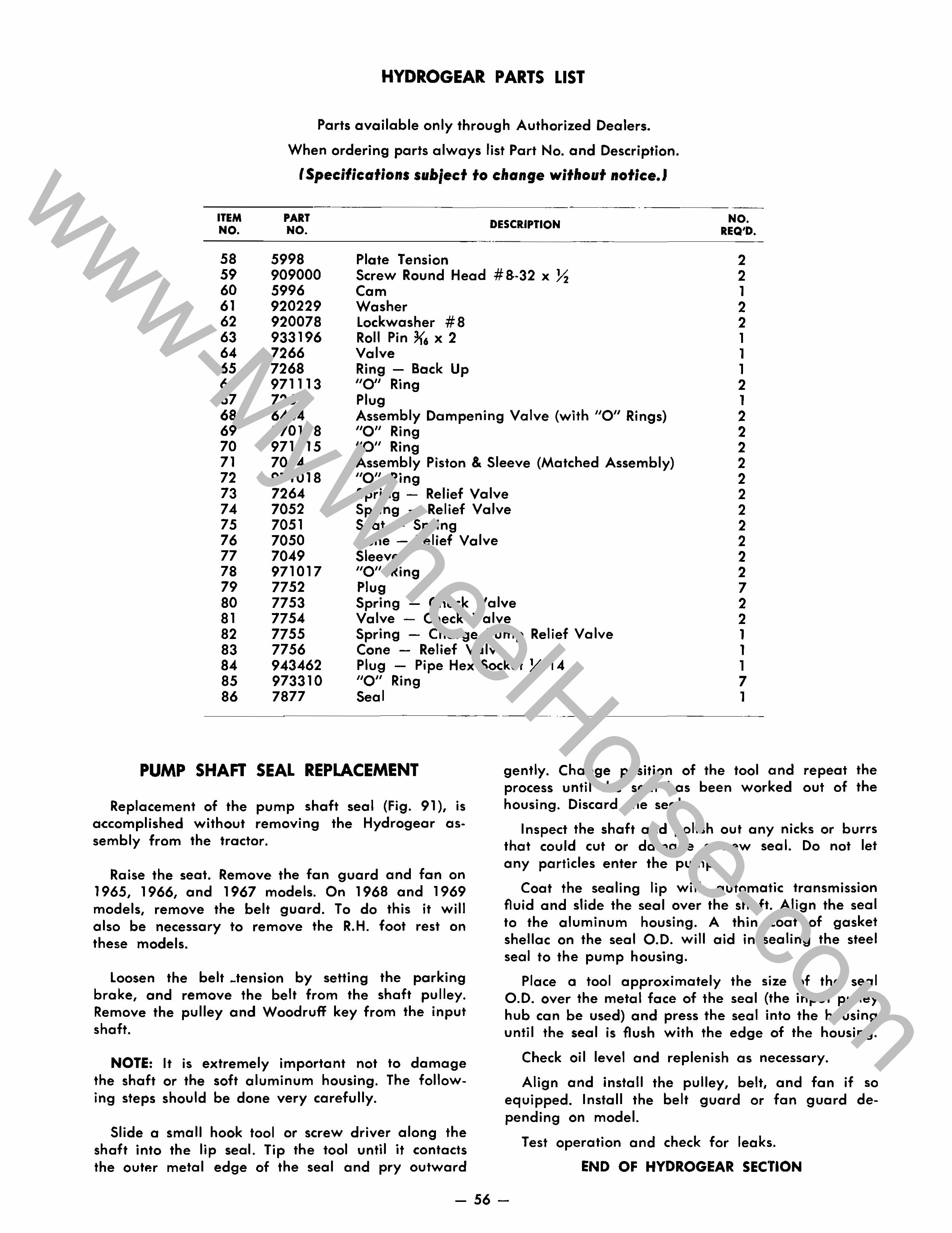
ITEM NO.
58 59 60 61 62 63 64 65 66 67 68 69 70 71 72 73 74 75 76 77 78 79 80 81 82 83 84 85 86
HYDROGEAR PARTS LIST
Parts available only through Authorized Dealers.
When ordering parts always list Part No. and Description.
(Specifications subject to change without notice. I
PART NO.
5998 909000 5996 920229 920078 933196 7266 7268 971113 7267 6444 970118 971015 7054 971018 7264 7052 7051 7050 7049 971017 7752 7753 7754 7755 7756 943462 973310 7877
DESCRIPTION
Plate Tension Screw Round Head # 8-32 x X Cam Washer lockwasher # 8 Roll Pin 3{6 x 2 Valve Ring - Back Up "0" Ring Plug Assembly Dampening Valve (with "0" Rings) "0" Ring "0" Ring Assembly Piston & Sleeve (Matched Assembly) "0" Ring Spring - Relief Valve Spring - Relief Valve Seat - Spring Cone - Relief Valve Sleeve "0" Ring Plug Spring - Check Valve Valve - Check Valve Spring - Charge Pump Relief Valve Cone - Relief Valve Plug - Pipe Hex Socket X-14 "0" Ring Seal
NO. REQ'D.
2 2 1 2 2 1 1 1 2 1 2 2 2 2 2 2 2 2 2 2 2 7 2 2 1 1 1 7 1
------------------- ~-- .. ~--~------------
PUMP SHAFT SEAL REPLACEMENT
Replacement of the pump shaft seal (Fig. 91), is accomplished without removing the Hydrogear assembly from the tractor.
Raise the seat. Remove the fan guard and fan on 1965, 1966, and 1967 models. On 1968 and 1969 models, remove the belt guard. To do this it will also be necessary to remove the R.H. foot rest on these models.
Loosen the belt _tension by setting the parking brake, and remove the belt from the shaft pulley. Remove the pulley and Woodruff key from the input shaft.
NOTE: It is extremely important not to damage the shaft or the soft aluminum housing. The following steps should be done very carefully.
Slide a small hook tool or screw driver along the shaft into the lip seal. Tip the tool until it contacts the outp.r metal edge of the seal and pry outward
gently. Change position of the tool and repeat the process until the seal has been worked out of the housing. Discard the seal.
Inspect the shaft and polish out any nicks or burrs that could cut or damage a new seal. Do not let any particles enter the pump.
Coat the sealing lip with automatic transmission fluid and slide the seal over the shaft. Align the seal to the aluminum housing. A thin coat of gasket shellac on the seal 0.0. will aid in sealing the steel seal to the pump housing.
Place a tool approximately the size of the seal 0.0. over the metal face of the seal (the input pulley hub can be used) and press the seal into the housing until the seal is flush with the edge of the housing.
Check oil level and replenish as necessary.
Align and install the pulley, belt, and fan if so equipped. Install the belt guard or fan guard depending on model.
Test operation and check for leaks.
END OF HYDROGEAR SECTION
- 56-
www-MyWheelHorse-com
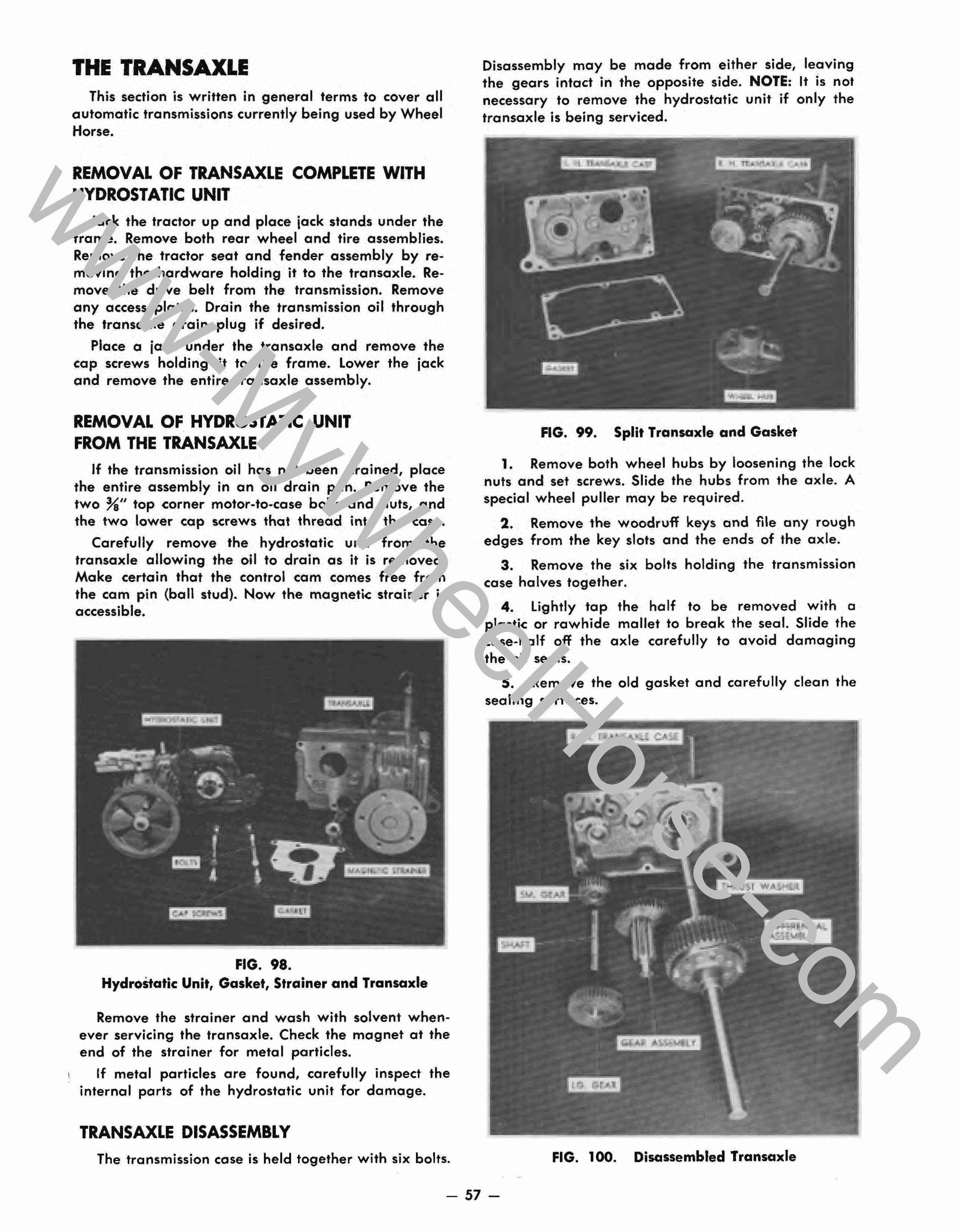
THE TRANSAXLE This section is written in general terms to cover all
automatic transmi.ssions currently being used by Wheel Horse.
REMOVAL OF TRANSAXLE COMPLETE WITH HYDROSTATIC UNIT
Jack the tractor up and place jack stands under the frame. Remove both rear wheel and tire assemblies. · Remove the tractor seat and fender assembly by removing the hardware holding it to the transaxle. Remove the drive belt from the transmission. Remove any access plates. Drain the transmission oil through the transaxle drain plug if desired.
Place a jack under the transaxle and remove the cap screws holding it to the frame. Lower the jack and remove the entire transaxle assembly.
REMOVAL OF HYDROSTATIC UNIT FROM THE TRANSAXLE
If the transmission oil has not been drained, place the entire assembly in an oil drain pan. Remove the two %/1 top corner motor-to-case bolts and nuts, and the two lower cap screws that thread into the case.
Carefully remove the hydrostatic unit from the transaxle allowing the oil to drain as it is removed. Make certain that the control cam comes free from the cam pin (ball stud). Now the magnetic strainer is accessible.
FIG. 98. HydroStatic Unit, Gasket, Strainer and Transaxle
Remove the strainer and wash with solvent whenever servicing the transaxle. Check the magnet at the end of the strainer for metal particles.
If metal particles are found. carefully inspect the internal parts of the hydrostatic unit for damage.
TRANSAXLE DISASSEMBLY The transmission case is held together with six bolts.
Disassembly may be made from either side, leaving the gears intact in the opposite side. NOTE: It is not necessary to remove the hydrostatic unit if only the transaxle is being serviced.
FIG. 99. Split Transaxle and Gasket
1. Remove both wheel hubs by loosening the lock nuts and set screws. Slide the hubs from the axle. A special wheel puller may be required.
2. Remove the woodruff keys and file any rough edges from the key slots and the ends of the axle.
3. Remove the six bolts holding the transmission case halves together.
4. Lightly tap the half to be removed with a plastic or rawhide mallet to break the seal. Slide the case-half off the axle carefully to avoid damaging the oil seals.
5. Remove the old gasket and carefully clean the sealing surfaces.
FIG. 100. Disassembled Transaxle
- 57-
www-MyWheelHorse-com
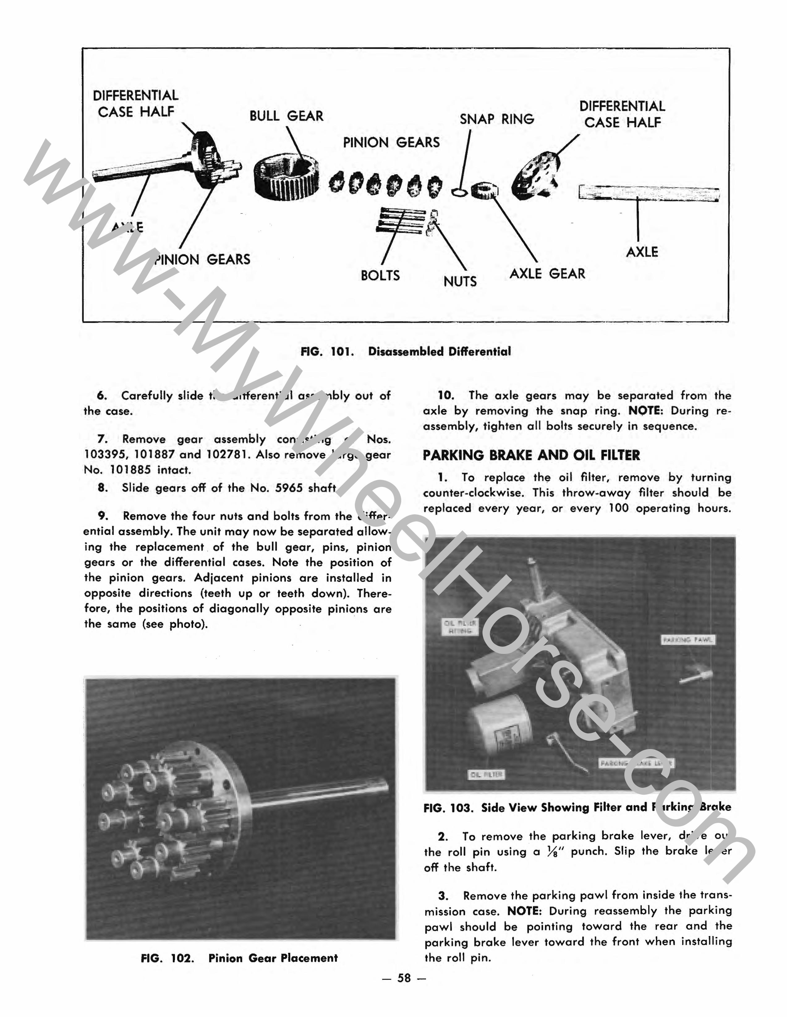
DIFFERENTIAL CASE HALF BULL GEAR SNAP RING
DIFFERENTIAL CASE HALF
PINION GEARS
AXLE
PINION GEARS AXLE
BOLTS NUTS AXLE GEAR
FIG. 101. Disassembled Differential
6. Carefully slide the differential assembly out of the case.
7. Remove gear assembly consisting of Nos. 103395, 101887 and 102781. Also remove large gear No. 101885 intact.
8. Slide gears off of the No. 5965 shaft.
9. Remove the four nuts and bolts from the differential assembly. The unit may now be separated allowing the replacement . of the bull gear, pins, pinion gears or the differential cases. Note the position of the pinion gears. Adjacent pinions are installed in opposite directions (teeth up or teeth down). Therefore, the positions of diagonally opposite pinions are the same (see photo).
FIG. 102. Pinion Gear Placement
10. The axle gears may be separated from the axle by removing the snap ring. NOTE: During reassembly, tighten all bolts securely in sequence.
PARKING BRAKE AND OIL FILTER
1. To replace th~ oil filter, remove by turning counter-clockwise. This throw-away filter should be replaced every year, or every 100 operating hours.
FIG. 103. Side View Showing Filter and Parking Brake
2. To remove the parking brake lever, drive out the roll pin using a Ya" punch. Slip the brake lever off the shaft.
3. Remove the parking pawl from inside the transmission case. NOTE: During reassembly the parking pawl should be pointing toward the rear and the parking brake lever toward the front when installing the roll pin.
- 58-
www-MyWheelHorse-com
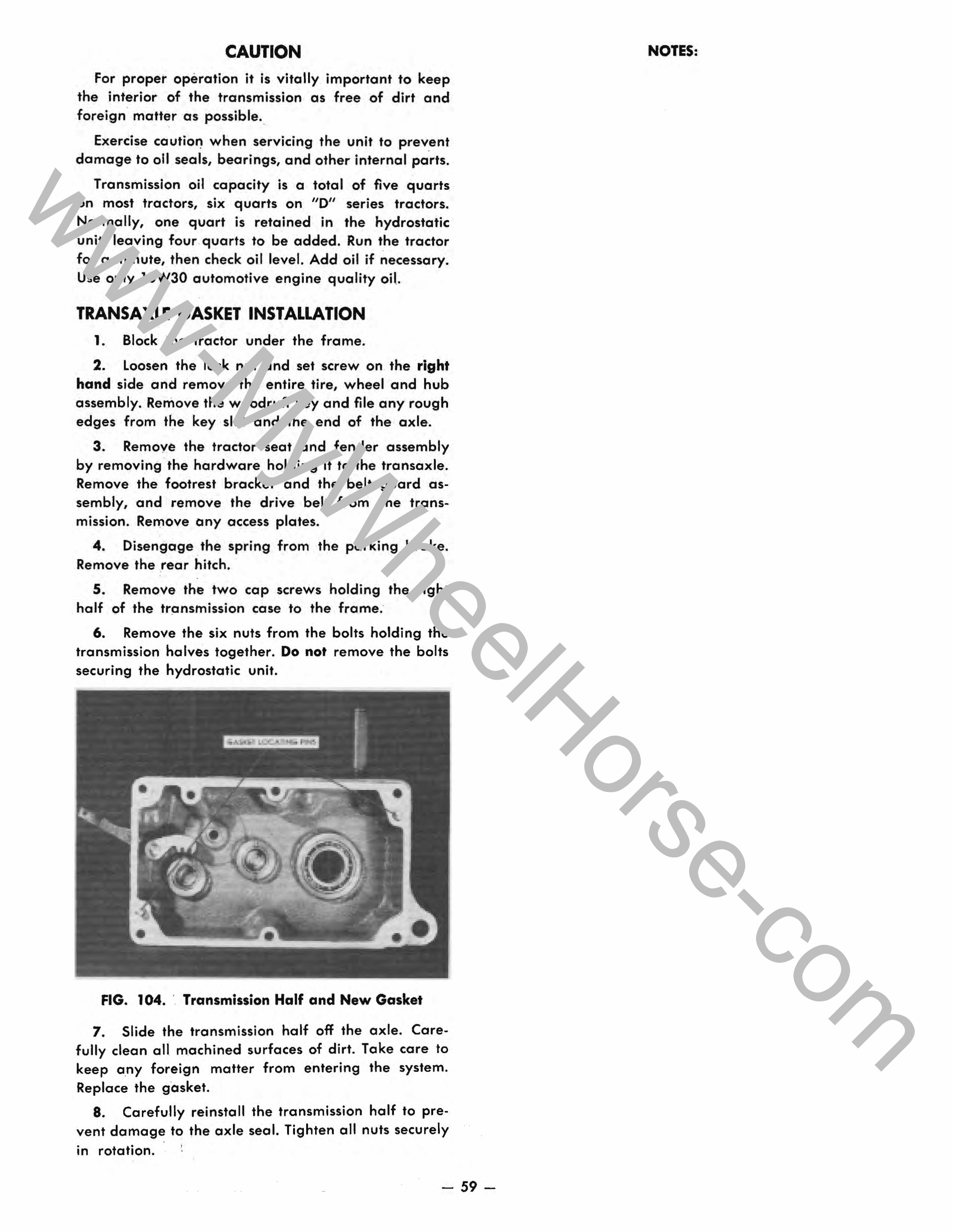
CAUTION For proper operation it is vitally important to keep
the interior of the transmission as free of dirt and foreign matter as possible ..
Exercise caution when servicing the unit to prevent damage to 011 seals, bearings, and other internal parts.
Transmission oil capacity is a total of five quarts on most tractors, six quarts on "0" series tractors. Normally, one quart is retained in the hydrostatic unit, leaving four . quarts to be added. Run the tractor for a minute, then check oil level. Add oil if necessary. Use only 10W30 automotive engine quality oil.
TRANSAXLE GASKET INSTALLATION 1. Block the tractor under the frame.
2. Loosen the lock nut and set screw on the right hand side and remove the entire tire, wheel and hub assembly. Remove the woodruff key and file any rough edges from the key slot and the end of the axle.
3. Remove the tractor seat and fender assembly by removing the hardware holding it to the transaxle. Remove the footrest bracket and the belt guard assembly, and remove the drive belt from the transmission. Remove any access plates.
4. Disengage the spring from the parking brake. Remove the rear hitch.
5. Remove the two cap screws holding the right half of the transmission case to the frame.
6. Remove the six nuts from the bolts holding the transmission halves together. Do not remove the bolts securing the hydrostatic unit.
FIG. 104. ' Transmission Half and New Gasket
7. Slide the transmission half off the axle. Carefully clean all machined surfaces of dirt. Take care to keep any foreign matter from entering the system. Replace the gasket.
8. Carefully reinstall the transmission half to prevent damage to the axle seal. Tighten all nuts securely in rotation.
- 59-
NOTES:
www-MyWheelHorse-com
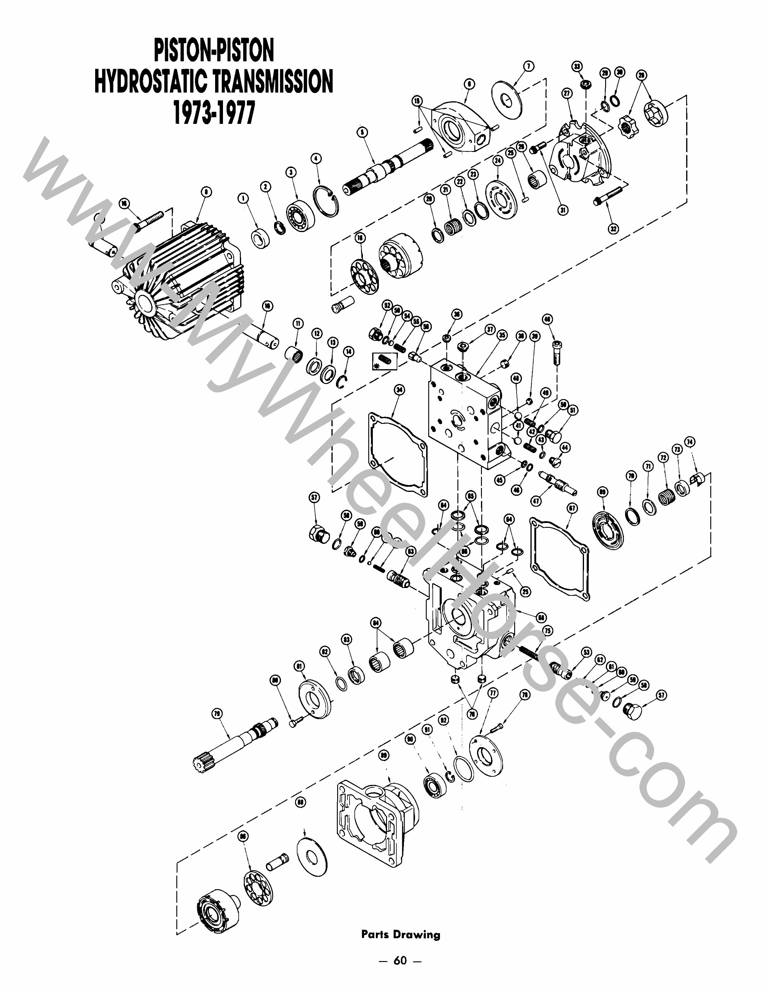
PISTON·PISTON HYDROSTATIC TRANSMISSION
1973·1977
./ ~
/ .. ( 1
I 1/
~ 13 C8 ="14
( I I I I
/
/'
/' ""' /'
I /' ,,'-~/'
Parts Drawing
- 60-
/1 / 1
/
I 1
./
/'" /'"
/' /'
/'"
/'"
/' /'"
/'" /
/ /'
/'"
~ I
/'
"'~ I
/' /'"
/'"
I I I I I
/
<!p® \ \
71 . \ \
~ i ~~
I ,)
www-MyWheelHorse-com
ITEM NO.
PART NO.
PARTS LIST 1973-1977* PISTON-PISTON HYDROSTATIC TRANSMISSION
Parts available only through Authorized Dealers. When ordering parts always list Part No. and Description.
(SpecNications subject to change without notice.)
DESCRIPTION NO. REO'D.
---------------------------------------------1 2 3 4 5 6 7 8 9
10 11 12 13 14 15 16
18 20 21 22 23 24 25 26 27 28 29 30 31 32 33 34 35 36 37 38 39 40 41 42 43 44 45 46 47
7877 83-3870 200214 200215 200213 200217 83-3750 200216 83-3900 83-3890 83-3910 103461 103462 103463 83-3880 200239 200219
200212 83-3920 200244 200245 200208 200220 83-3820 200222 200224 83-3860 971018 103184 200231 200230 200226 83-3850 200238 200241 200226 200227 83-3830 83-3730 103216 103457 973310 103458 971012 103459 103460
Pump Shaft Seal Snap Ring (Formerly 200229) Ball Bearing Snap Ring Pump Shaft Variable Swash Plate Thrust Plate (Formerly 200188) Pump Housing Stub Trunnion Shaft (Formerly 200236) Control Trunnion Shaft (Formerly 200235) Needle Bearing (Formerly 200237) Seal Washer Retaining Ring Spirol Pin (Formerly 200234) Cap Screw Cylinder Block Kit Consists of nine pistons and a cylinder block (not available separately) plus the correct number of items 18, 20, 21, 22 & 23. Slipper Retainer Washer (Formerly 200243) Spring Front Washer Retaining Ring Valve Plate Locating Pin (Formerly 200198) Needle Bearing Charge Pump Housing Gerotor Assembly (Formerly 200225) O-Ring, Large Back Up Ring Cap Screw, Short Cap Screw, Long Socket Head Plug Pump Gasket (Formerly 200223) Pump End Cap Socket Head Plug Socket Head Plug Pipe Plug Pipe Plug, 1J4u (Formerly 200199) Cap Screw, Short (Formerly 200184) Ball Check Valve Spring O-Ring Check Valve Plug O-Ring Back Up Ring Push Valve
* Refer to specific tractor parts manual to determine replacement parts information for 1978-1980 tractors.
- 61 -
1 1 1 1 1 1 1 1 1 1 2 2 2 2 3 4
1 1 1 1 1 1 2 1 1 1 2 2 2 2 2 1 1 1 1 1 2 2 2 2 2 2 1 1 1
www-MyWheelHorse-com
ITEM NO.
48 49 50 51 52 53 54 55 56 57 58 59 60 61 62 63 64 65 66 67 68 69
70 71 72 73 74 75 76 77 78 79 80 81 82 83 84 86 88 89 90 91 92 93 94 95
PART NO.
103216 103455 973310 7752 103465 103588 103574 103464 6632 103593 973500 103591 973190 103590 103589 103588 971015 103184 971018 83-3760 200193 200203 200190
200208 200209 200210 200211 200204 103592 83-3830 103840 200200 105124 83-3790 83-3780 200205 83-3800 83-3770 200212 83-3750 200189 200187 200206 970132 200185 83-3740 200202
PARTS LIST 1973-1977 PISTON-PISTON HYDROSTATIC TRANSMISSION
Parts available only through Authorized Dealers. When ordering parts always list Part No .. and Description.
(Specifications subject to change vJlthout notice.)
DESCRIPTION
Ball Charge Relief Valve Spring O-Ring Plug Plug Acceleration Valve Body Shim Set Implement Relief Valve Spring Relief Valve Cone Hex Plug O-Ring Metering Plug O-Ring Ball Spring Acceleration Valve Assembly O-Ring Back Up Ring O-Ring Motor Gasket (Formerly 200191) Motor End Cap Valve Plate Cylinder Block Kit - Consists of nine pistons and a cylinder block (not available separately) plus the correct number of items 70, 71, 72, 73 & 86. Retaining Ring Washer Spring Retainer Retaining Clip Acceleration Valve Spring Pipe Plug (Formerly 200199) Motor Cover Plate Cap Screw Motor Shaft (Formerly 200197) CapScrew (Formerly 200195) Centering Pilot (Formerly 2001 ~4) O-Ring Seal Retainer With O-Ring (Formerly 200196) Needle Bearing (Formerly 200192) Slipper Retainer Thrust Plate (Formerly 200188) Motor Housing Ball Bearing Retaining Ring O-Ring Copper Washer Socket Head Cap Screw (Formerly 200186) Hex Head Cap Screw
* Tractors not equipped with a hydraulic lift use spring No.1 03455 here, and only the plug (item 51) and o-ring (50) on the opposite side.
- 62-
NO. REO'D.
1 1 2 1 1 1 1 1 1 1 2 2 2 2 2 2 3 2 2 1 1 1
1 1 1 1 1 1 2 1 4 1 2 1 1 1 2 1 1 1 1 1 1 1 2 4
www-MyWheelHorse-com
Bulletin No.
62
64
67
68
80
83
84
101
118
437
172
174
195
217
252
273
305
437
NOTE:
SERVICE BULLETIN RECORD
Date Issued Topic or Part Involved
3/65
4/65
7/65
9/65
12/66
1/67
2/67
7/68
12/69
3/89
4/75
5/75
12/76
2/78
11/79
5/80
4/81
3/89
Hydrogear Bulletins
Hydrogear - Transaxle Gasket Replacement
Hydrogear - Kit 6059, for use with Sickle Bar mower.
Hydrogear - Oil leak due to loose slide casting.
Hydrogear - Kit 6066, for correcting oil leak at cam block trunnion support casting or serial number plate.
Hydrogear - TransmissionfTransaxle usage and interchangeability 1967 and prior.
Hydrogear - New relief valve spring 7264; relates to tiller installation on earlier units.
Hydrogear - Oil and filter change recommendation. (Note Dexron II is present equivalent to Type A Automatic Transmission fluid).
Hydrogear - Replacement unit installation information.
Hydrogear - Securing hydraulic valve hoses.
Hydrogear - Sundstrand rebuilding service.
Piston - Piston Bulletins
Piston-Piston - Use of rust preventative on axles.
Piston-Piston - Differential bolt diameter change.
Piston-Piston - Motor snap ring failure, 1975 and prior tractors; S/A 105124
Piston-Piston - Driven coupling installation on D-Series tractors, 1977 and prior: S/A 105147. Also see SB 305.
Piston-Piston - Conversion of limited slip to 8-pinion differential, 1968-73 tractors; S/A 105173/Gear 101523.
Piston-Piston - Differential end cap nut 108881.
Piston-Piston - Driven coupling repair procedure, D-Series tractors.
Piston-Piston - Sundstrand rebuilding service.
Service Bulletin information is for repair reference purposes. Parts and assemblies covered by bulletin may no longer be available. Warranty coverage has expired for all Sundstrand-equipped products.
www-MyWheelHorse-com