volumetric reactor productivity - rvp
TRANSCRIPT
ChE 471: LECTURE 2B. Fall - September 2004
2. IDEAL REACTORS
One of the key goals of chemical reaction engineering is to quantify
the relationship between production rate, reactor size, reaction
kinetics and selected operating conditions. This requires a
mathematical model of the system, which in turn rests on application
of conservation laws to a well-defined control volume of the reaction
system and on use of appropriate constitutive expressions for the
reaction rates. The concepts of ideal reactors allow us to quantify
reactor performance as a function of its size and selected operating
conditions.
To illustrate this useful concept we deal here with a single,
homogeneous phase, single reaction at constant temperature. We
introduce then the ideal batch reactor, and two ideal continuous flow
reactors. In each case we apply the conservation of species mass
principle which states
(Rate of Accumulation) = (Rate of Input) – (Rate of Output) + (Rate of
Generation) (2-1)
Equation (2-1) is applied to an appropriately selected control volume,
the largest arbitrarily selected volume of the system in which there
are no gradients in composition.
2.1 Batch Reactor1
The ideal batch reactor is assumed to be perfectly mixed. This
implies that at a given moment in time the concentration is uniform
throughout the vessel. The volume, V in the development below is
assumed equal to the volume of the reaction mixture. This is then
equal to the reactor volume VR in case of gas phase reaction but not
in case of liquids (V< VR, then). The batch reactor can be an
autoclave of V = const (Figure 2.1-a) and a constant pressure, P =
const) (Figure 2.1-b) vessel. The former is almost always encountered
in practice.
Our goal is:
a) To find a relationship between species concentration (reactant
conversion) and time on stream.
b) To relate reactor size and production rate.
Let us consider a single irreversible reaction with an n-th
order irreversible rate of reaction
(2-2)
At t = 0 a batch of volume V is filled with fluid of concentration
CAo. Reaction is started (nAo= CAoVo). Find how reactant conversion
depends on reaction time? Also determine the production rate as a
function of reaction time.
We apply (eq 2-1) to reactant A:
(2-3)
2
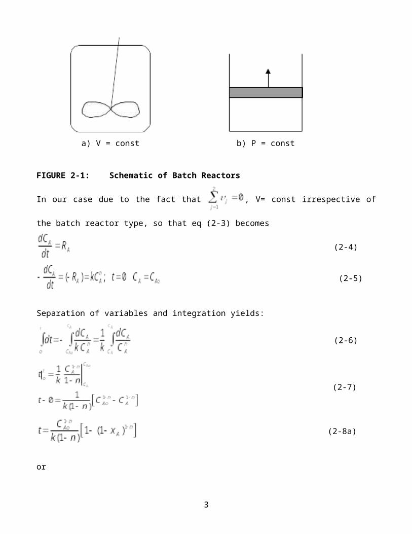
a) V = const b) P = const
FIGURE 2-1: Schematic of Batch Reactors
In our case due to the fact that , V= const irrespective of
the batch reactor type, so that eq (2-3) becomes
(2-4)
(2-5)
Separation of variables and integration yields:
(2-6)
(2-7)
(2-8a)
or
3
(2-8b)
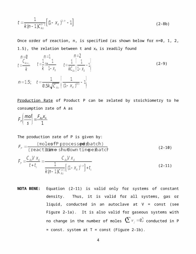
Once order of reaction, n, is specified (as shown below for n=0, 1, 2,
1.5), the relation between t and xA is readily found
(2-9)
Production Rate of Product P can be related by stoichiometry to he
consumption rate of A as
The production rate of P is given by:
(2-10)
(2-11)
NOTA BENE: Equation (2-11) is valid only for systems of constant
density. Thus, it is valid for all systems, gas or
liquid, conducted in an autoclave at V = const (see
Figure 2-1a). It is also valid for gaseous systems with
no change in the number of moles conducted in P
= const. system at T = const (Figure 2-1b).
4
The first equality in equation (2-11) gives the general result, the
second equality presents the result for an n-th order irreversible
reaction with respect to reactant A.
To use this equation the shut down time, i.e. the time needed between
batches, ts, must be known. Consider now the following second order
reaction with stoichiometry A = P.
a) Find the batch reactor volume needed to produce FP = 38 (mol/min)
if reactor shut down time is 60 minutes and the desired
conversion is 0.95. Initial reactant concentration is CAo = 1
(mol L).
Using the right form of equation (2-9) for n = 2 we get the
reaction time.
Then, solving equation (2-11) for the volume we get
b) What is the maximum production rate, FP, achievable in the above
batch reactor of volume V=10m3 if ts, T, CAo all are fixed at
previous values.
5
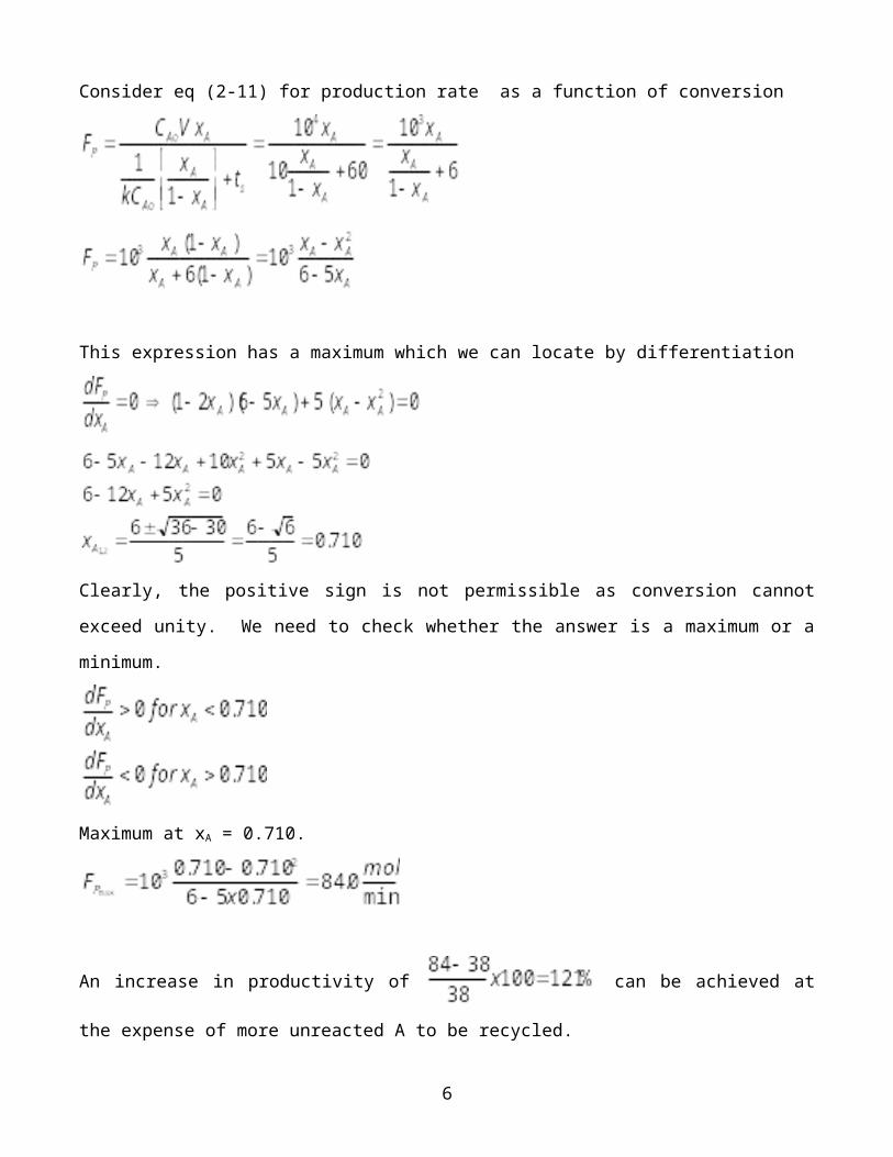
Consider eq (2-11) for production rate as a function of conversion
This expression has a maximum which we can locate by differentiation
Clearly, the positive sign is not permissible as conversion cannot
exceed unity. We need to check whether the answer is a maximum or a
minimum.
Maximum at xA = 0.710.
An increase in productivity of can be achieved at
the expense of more unreacted A to be recycled.
6
One must include the cost of separation into the real economic
optimization.
2.2 Continuous Flow Reactors (Steady State)
2.2.1 Continuous Flow Stirred Tank Reactor (CFSTR or CSTR or
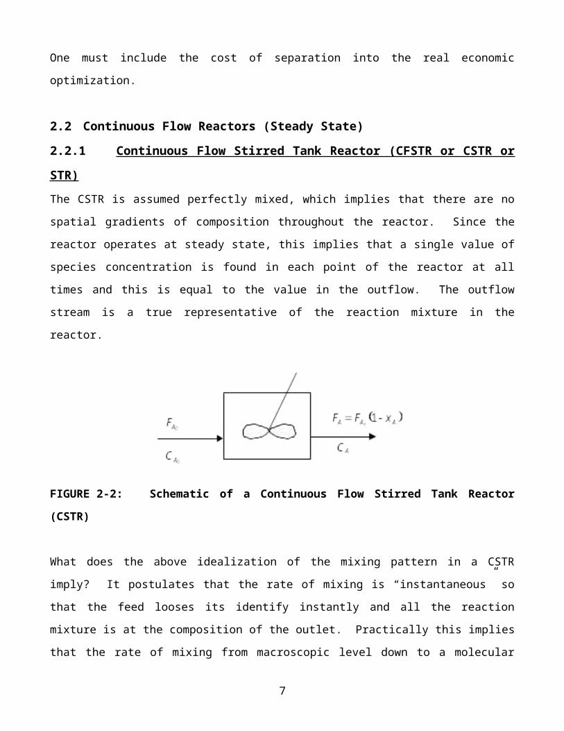
STR)The CSTR is assumed perfectly mixed, which implies that there are no
spatial gradients of composition throughout the reactor. Since the
reactor operates at steady state, this implies that a single value of
species concentration is found in each point of the reactor at all
times and this is equal to the value in the outflow. The outflow
stream is a true representative of the reaction mixture in the
reactor.
FIGURE 2-2: Schematic of a Continuous Flow Stirred Tank Reactor
(CSTR)
What does the above idealization of the mixing pattern in a CSTR
imply? It postulates that the rate of mixing is “instantaneous” so
that the feed looses its identify instantly and all the reaction
mixture is at the composition of the outlet. Practically this implies
that the rate of mixing from macroscopic level down to a molecular
7
scale is orders of magnitude faster than the reaction rate and is so
fast in every point of the vessel.
Then the mass balance of eq (2-1) can be applied to the whole volume
of the reactor recognizing that at steady state the accumulation term
is identically zero. Again, taking a simple example of an
irreversible reaction A P application of eq (2-1) to reactant A
yields:
FAo – FA + ((RA)V=0 (2-12)
Molar flow rate of unreacted A in the outflow by definition is given
by FA = FAo (1-xA) = Q CAo (1-xA). The production rate of P is given
by
(2-13)
Reactor volume is given by eq (2-12)
(2-14)
Reactor space time is defined by
(2-15)
Using stoichiometry we readily develop the relation between production
rate, FP, and reactor volume, V.
Let us consider again the example of our 2nd order reaction, A = P,
with the rate below:8
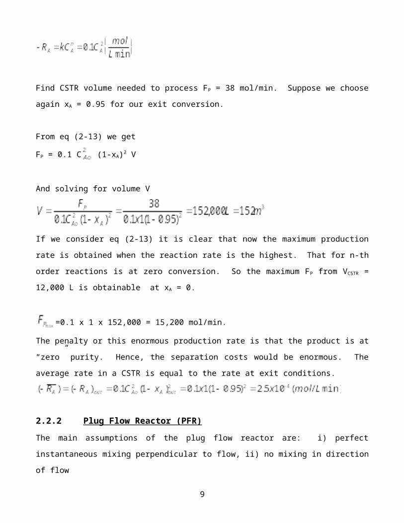
Find CSTR volume needed to process FP = 38 mol/min. Suppose we choose
again xA = 0.95 for our exit conversion.
From eq (2-13) we get
FP = 0.1 C (1-xA)2 V
And solving for volume V
If we consider eq (2-13) it is clear that now the maximum production
rate is obtained when the reaction rate is the highest. That for n-th
order reactions is at zero conversion. So the maximum FP from VCSTR =
12,000 L is obtainable at xA = 0.
=0.1 x 1 x 152,000 = 15,200 mol/min.
The penalty or this enormous production rate is that the product is at
“zero” purity. Hence, the separation costs would be enormous. The
average rate in a CSTR is equal to the rate at exit conditions.
2.2.2 Plug Flow Reactor (PFR) The main assumptions of the plug flow reactor are: i) perfect
instantaneous mixing perpendicular to flow, ii) no mixing in direction
of flow
9
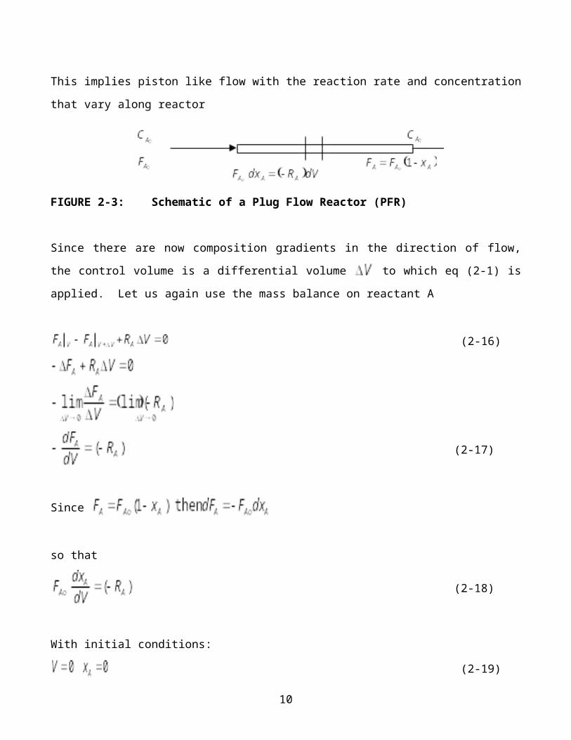
This implies piston like flow with the reaction rate and concentration
that vary along reactor
FIGURE 2-3: Schematic of a Plug Flow Reactor (PFR)
Since there are now composition gradients in the direction of flow,
the control volume is a differential volume to which eq (2-1) is
applied. Let us again use the mass balance on reactant A
(2-16)
(2-17)
Since
so that
(2-18)
With initial conditions:
(2-19)
10
Upon separation of variables in (eq 2-18) and integration:
(2-20)
For an n-th order reaction (with ) we get
(2-21)
The expression for the PFR space time
(2-22)
is now identical to the expression for reaction time, t, in the batch
reactor.
For the example of the second order reaction used earlier we get
FAo = Qo CAo
(Same as the expression for reaction time, t,
in the batch reactor)
Let us consider our example of the second order reaction and find the
PFR volume needed to produce FP = 38 mol/min11
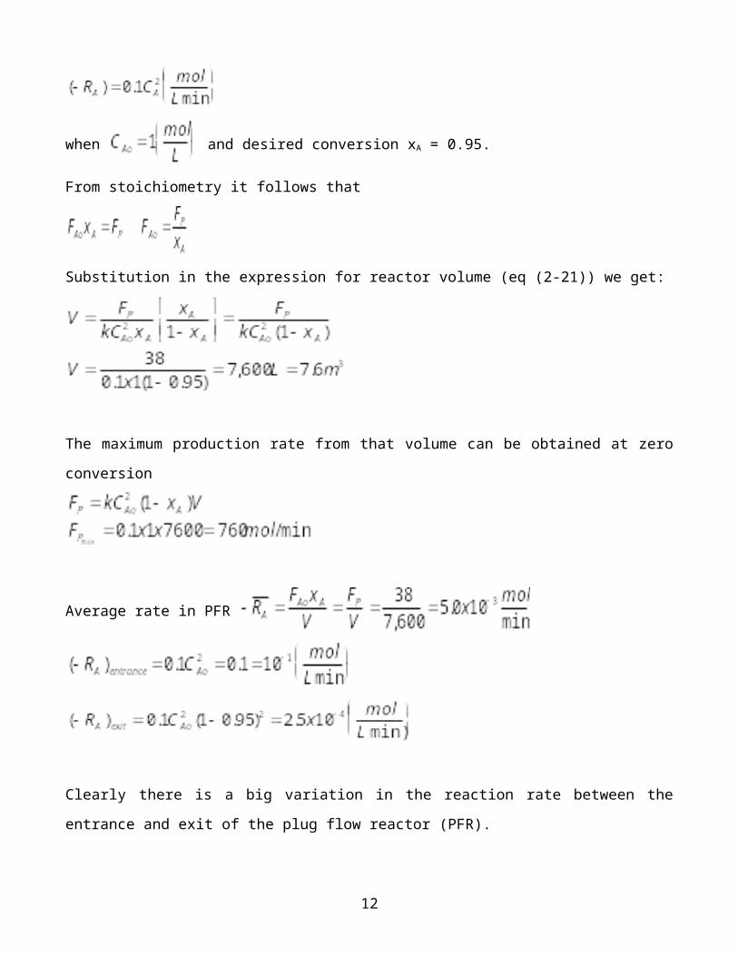
when and desired conversion xA = 0.95.
From stoichiometry it follows that
Substitution in the expression for reactor volume (eq (2-21)) we get:
The maximum production rate from that volume can be obtained at zero
conversion
Average rate in PFR
Clearly there is a big variation in the reaction rate between the
entrance and exit of the plug flow reactor (PFR).
12
2.3 STY – Space Time Yield
Volumetric Reactor Productivity - RVP
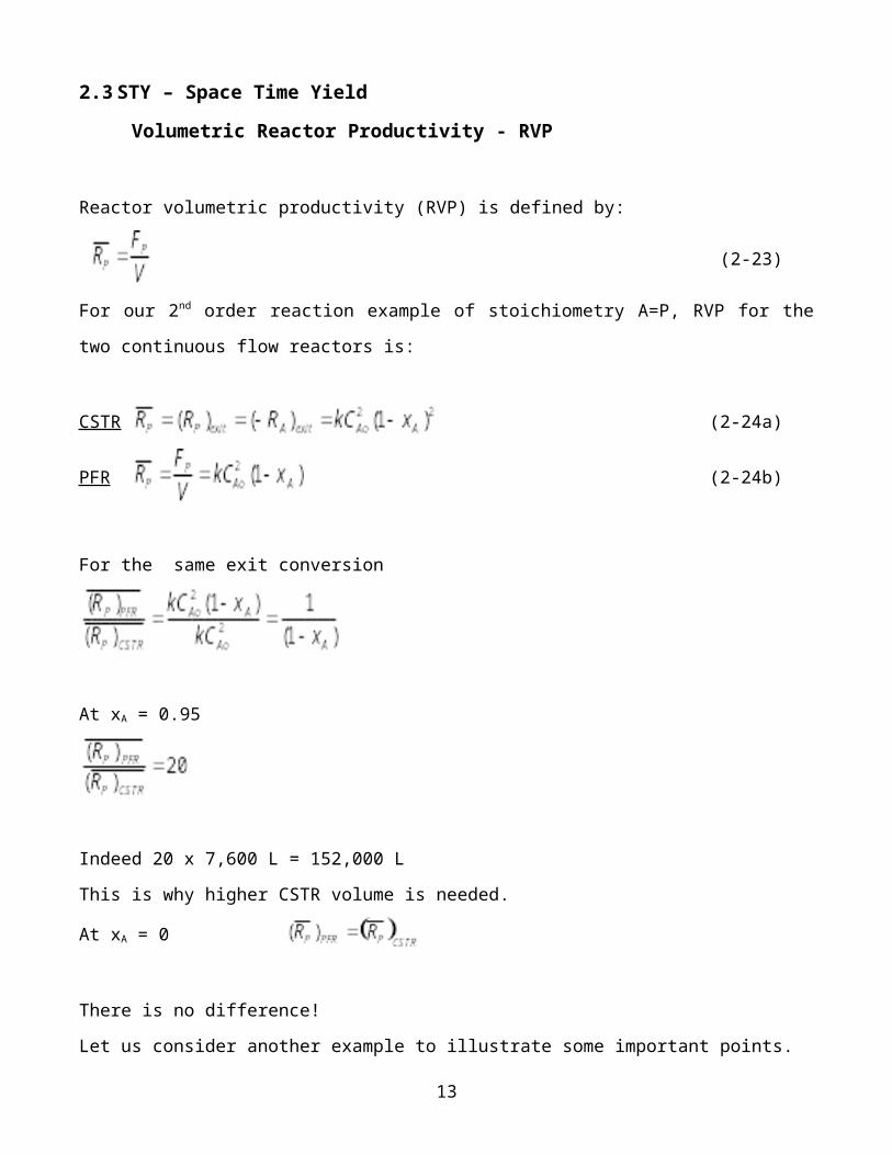
Reactor volumetric productivity (RVP) is defined by:
(2-23)
For our 2nd order reaction example of stoichiometry A=P, RVP for the
two continuous flow reactors is:
CSTR (2-24a)
PFR (2-24b)
For the same exit conversion
At xA = 0.95
Indeed 20 x 7,600 L = 152,000 L
This is why higher CSTR volume is needed.
At xA = 0
There is no difference!
Let us consider another example to illustrate some important points.
13
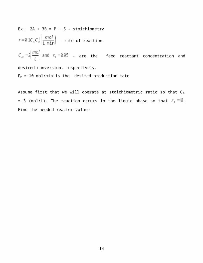
Ex: 2A + 3B = P + S – stoichiometry
- rate of reaction
- are the feed reactant concentration and
desired conversion, respectively.
FP = 10 mol/min is the desired production rate
Assume first that we will operate at stoichiometric ratio so that CBo
= 3 (mol/L). The reaction occurs in the liquid phase so that .
Find the needed reactor volume.
14
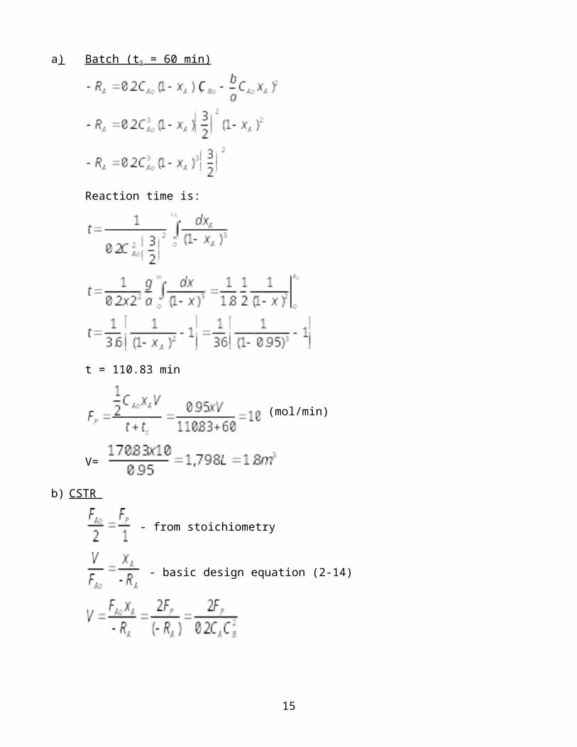
a) Batch (ts = 60 min)
Reaction time is:
t = 110.83 min
(mol/min)
V=
b) CSTR
- from stoichiometry
- basic design equation (2-14)
15
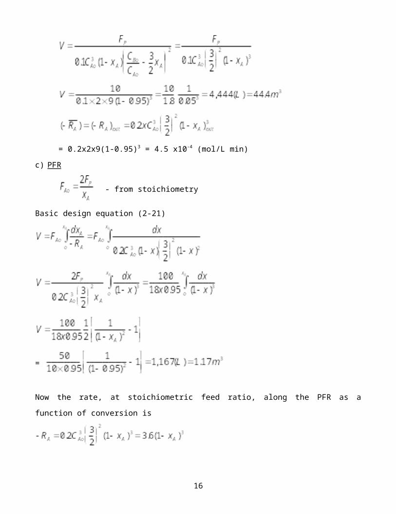
= 0.2x2x9(1-0.95)3 = 4.5 x10⁻⁴ (mol/L min)
c) PFR
- from stoichiometry
Basic design equation (2-21)
=
Now the rate, at stoichiometric feed ratio, along the PFR as a
function of conversion is
16
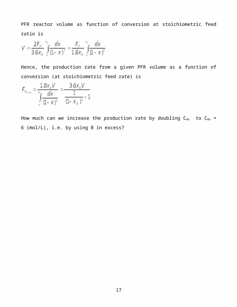
PFR reactor volume as function of conversion at stoichiometric feed
ratio is
Hence, the production rate from a given PFR volume as a function of
conversion (at stoichiometric feed rate) is
How much can we increase the production rate by doubling CBo to CBo =
6 (mol/L), i.e. by using B in excess?
17
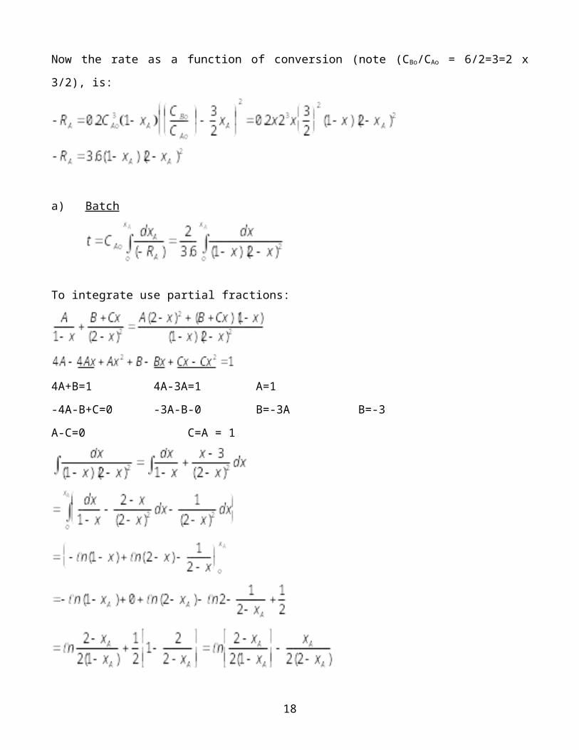
Now the rate as a function of conversion (note (CBo/CAo = 6/2=3=2 x
3/2), is:
a) Batch
To integrate use partial fractions:
4A+B=1 4A-3A=1 A=1
-4A-B+C=0 -3A-B-0 B=-3A B=-3
A-C=0 C=A = 1
18
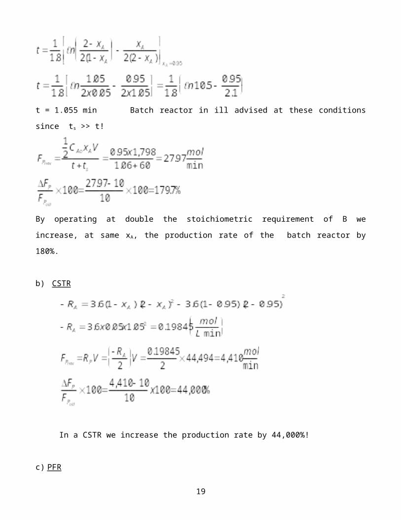
t = 1.055 min Batch reactor in ill advised at these conditions
since ts >> t!
By operating at double the stoichiometric requirement of B we
increase, at same xA, the production rate of the batch reactor by
180%.
b) CSTR
In a CSTR we increase the production rate by 44,000%!
c) PFR
19
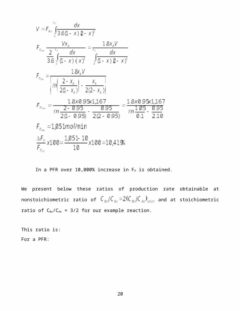
In a PFR over 10,000% increase in FP is obtained.
We present below these ratios of production rate obtainable at
nonstoichiometric ratio of and at stoichiometric
ratio of CBo/CAo = 3/2 for our example reaction.
This ratio is:
For a PFR:
20
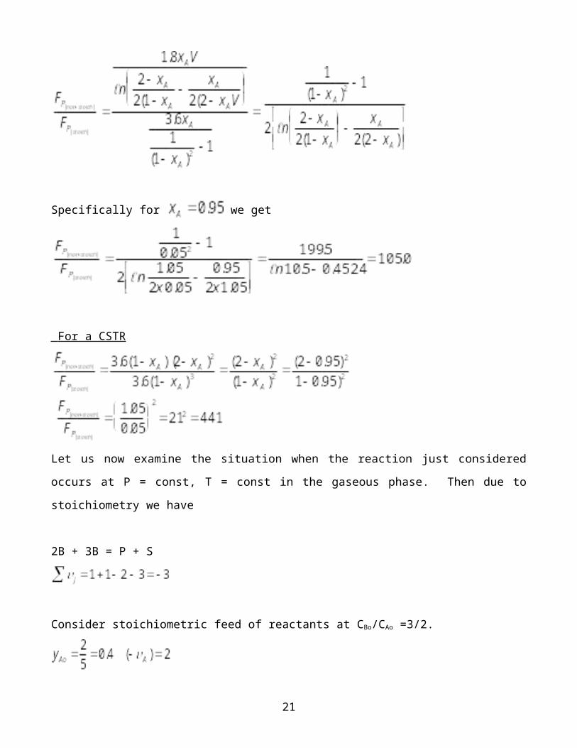
Specifically for we get
For a CSTR
Let us now examine the situation when the reaction just considered
occurs at P = const, T = const in the gaseous phase. Then due to
stoichiometry we have
2B + 3B = P + S
Consider stoichiometric feed of reactants at CBo/CAo =3/2.
21
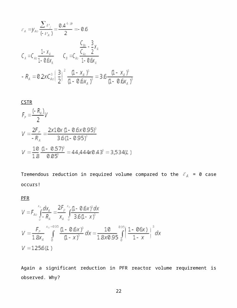
CSTR
Tremendous reduction in required volume compared to the = 0 case
occurs!
PFR
Again a significant reduction in PFR reactor volume requirement is
observed. Why?
22
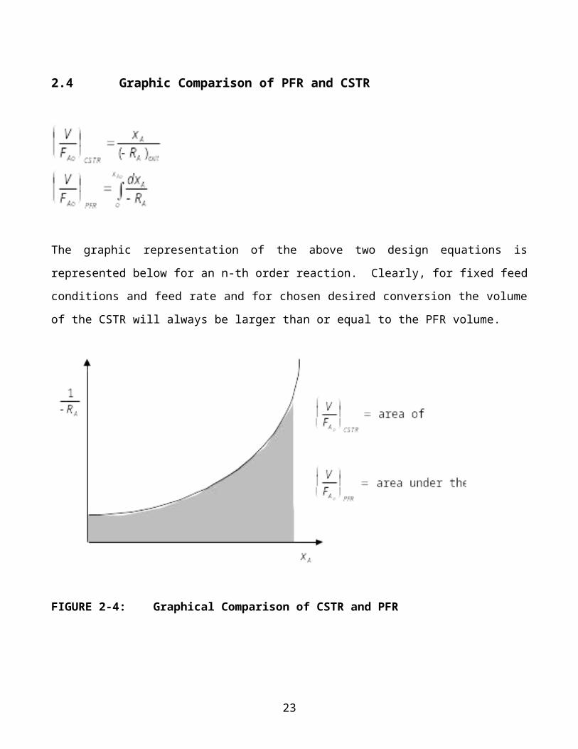
2.4 Graphic Comparison of PFR and CSTR
The graphic representation of the above two design equations is
represented below for an n-th order reaction. Clearly, for fixed feed
conditions and feed rate and for chosen desired conversion the volume
of the CSTR will always be larger than or equal to the PFR volume.
FIGURE 2-4: Graphical Comparison of CSTR and PFR
23