theory of single point incremental forming
TRANSCRIPT
THEORY OF SINGLE POINT INCREMENTAL FORMINGFORMING
P. A. F. Martins(a), N. Bay(b) (1), M. B. Silva(a), M. Skjoedt(b), y ( ), , j(a) Instituto Superior Tecnico, TULisbon, Portugal
(b) Department of Mechanical Engineering, Technical University of Denmark, Denmark
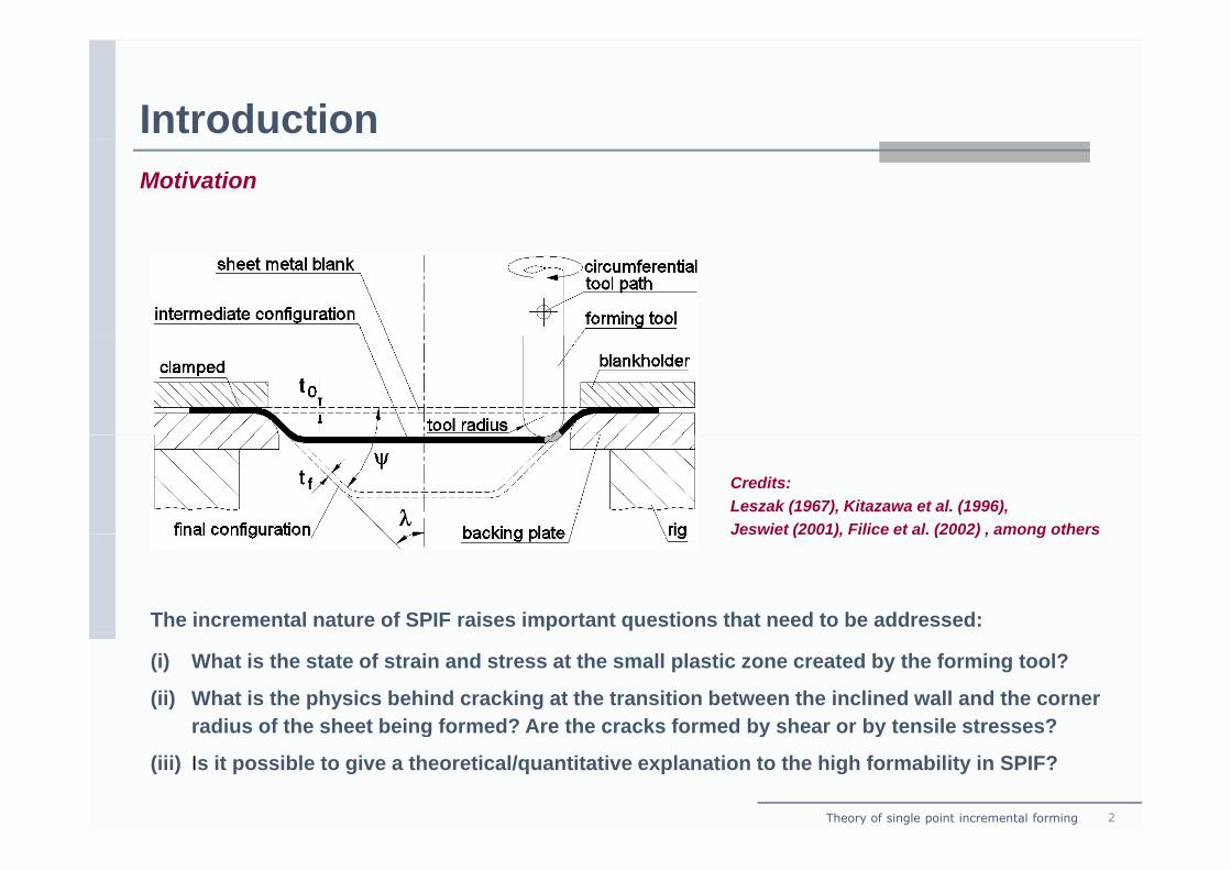
IntroductionMotivation
Credits:Leszak (1967), Kitazawa et al. (1996),Jeswiet (2001), Filice et al. (2002) , among others
The incremental nature of SPIF raises important questions that need to be addressed:
Jeswiet (2001), Filice et al. (2002) , among others
(i) What is the state of strain and stress at the small plastic zone created by the forming tool?
(ii) What is the physics behind cracking at the transition between the inclined wall and the corner radius of the sheet being formed? Are the cracks formed by shear or by tensile stresses?
Theory of single point incremental forming 2
radius of the sheet being formed? Are the cracks formed by shear or by tensile stresses?
(iii) Is it possible to give a theoretical/quantitative explanation to the high formability in SPIF?
IntroductionState-of-the-art
Until very recently SPIF was one of the very few - if not the only - sheet metal forming process inUntil very recently SPIF was one of the very few if not the only sheet metal forming process inwhich the advantage of experimentation over theory was absolute even for solving the simplestpractical problem.
Disputes in explanations on SPIF mechanics and formability:
(i) Deformation by stretching or shearing
(ii) F bilit li it d b ki f t(ii) Formability limited by necking or fracture
(iii) Raising of FLC due to through thickness shear
(iv) Raising of FLC due to serrated strain paths arising from cyclic, local plastic deformation
Credits:Jeswiet et al. (2007), Allwood , Shouler and Tekkaya (2007), Jackson and Allwood (2007), Emmens and van den Boogaard (2007),
( ) g p g y p
Eyckens et al. (2007), Silva et al. (2008), among others.
Theory of single point incremental forming 3
IntroductionObjective
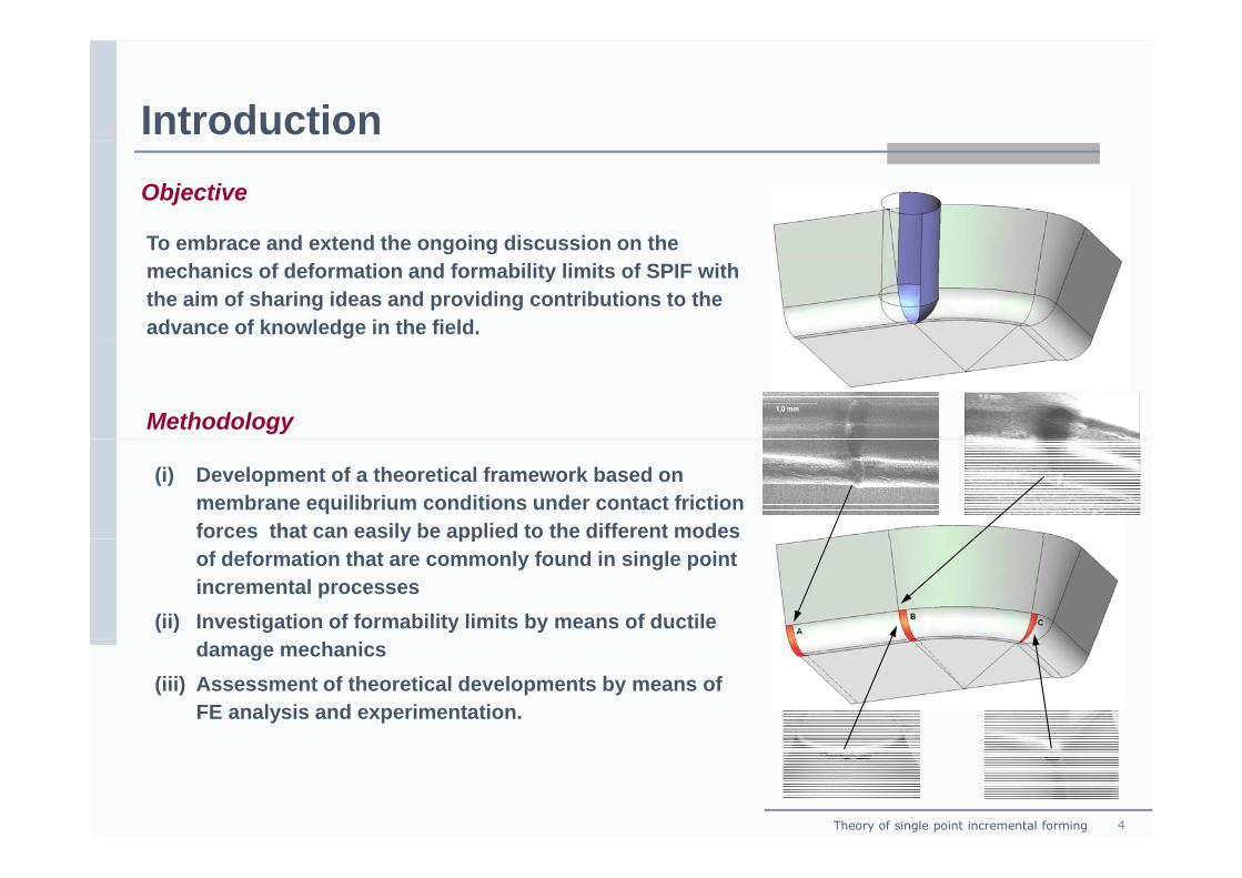
To embrace and extend the ongoing discussion on theTo embrace and extend the ongoing discussion on the mechanics of deformation and formability limits of SPIF with the aim of sharing ideas and providing contributions to the advance of knowledge in the field.
Methodology
(i) Development of a theoretical framework based on membrane equilibrium conditions under contact friction forces that can easily be applied to the different modes
y ppof deformation that are commonly found in single point incremental processes
(ii) Investigation of formability limits by means of ductile damage mechanics
(iii) Assessment of theoretical developments by means of FE analysis and experimentation.
Theory of single point incremental forming 4
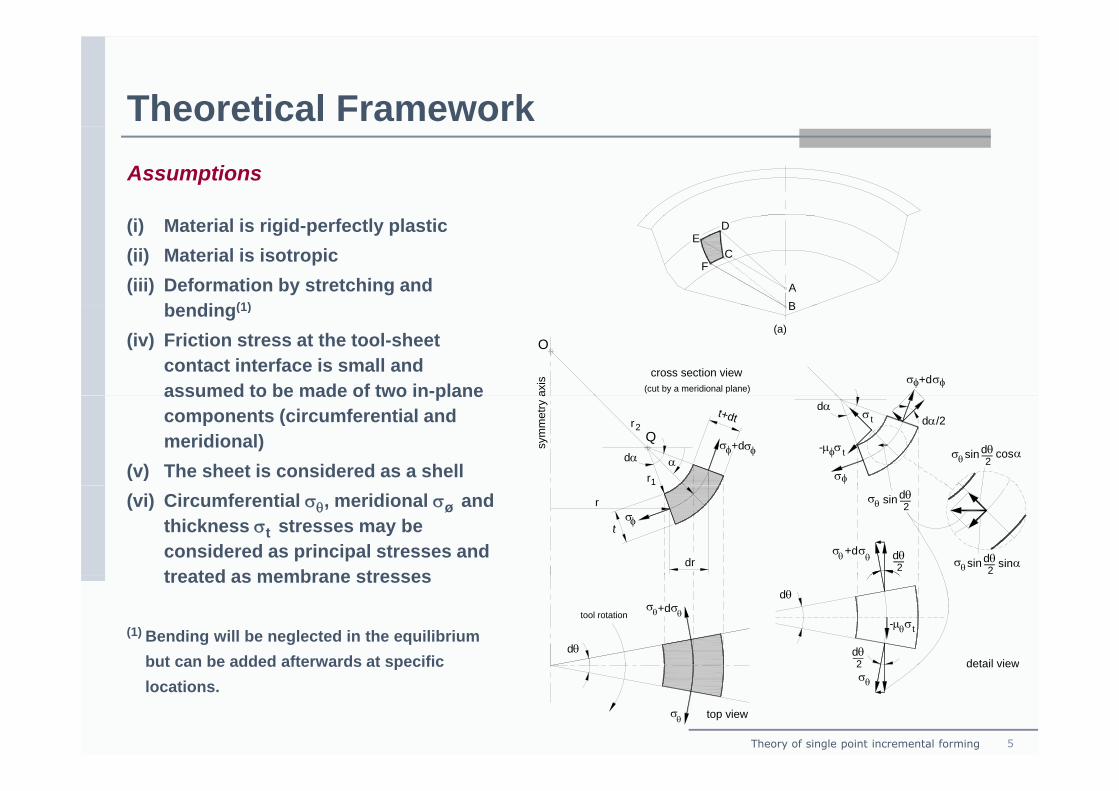
Theoretical FrameworkAssumptions
(i) Material is rigid-perfectly plastic(ii) Material is isotropic(iii) Deformation by stretching and
b di (1)AB
CF
ED
bending(1)
(iv) Friction stress at the tool-sheet contact interface is small and assumed to be made of two in-plane
B
(a)
axis
(cut by a meridional plane)
cross section view
O
σσ +dφ φassumed to be made of two in plane components (circumferential and meridional)
(v) The sheet is considered as a shelldα
+dσ σsym
met
ry a
t+dt
r1
r2
φ φQ
α
dα/2tσ
σ t
σ
dα
θσ cos α
φ
dθ2
sinφ-μ
(vi) Circumferential σθ, meridional σø and thickness σt stresses may be considered as principal stresses and treated as membrane stresses
σ
dr
r
tφ
σθ sinαdθ2
+dσ σθ θ
sinθσ2
dθ
sin dθ2treated as membrane stresses
(1) Bending will be neglected in the equilibrium but can be added afterwards at specific
dθ
σθ+dσθtool rotation
dθ
detail view2dθ
-μθσt
Theory of single point incremental forming 5
but can be added afterwards at specific locations.
σθ top view
detail viewθσ
2
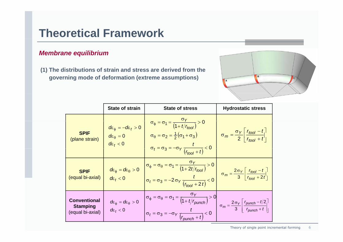
Theoretical FrameworkMembrane equilibrium
(1) The distributions of strain and stress are derived from the governing mode of deformation (extreme assumptions)
State of strain State of stress Hydrostatic stress
0>σY
SPIF(plane strain)
00
0
<ε
=ε
>ε−=ε
θ
φ
t
t
dd
dd ( )( )
( ) 0
01
3
3121
2
1
<σ−=σ=σ
σ+σ=σ=σ
>+
=σ=σ
θ
φ
t
rt
Yt
tool
Y
⎥⎦
⎤⎢⎣
⎡+−σ
=σtrtr
tool
toolYm 2
SPIF( l bi i l)
( ) 03 <+
σ=σ=σtrtool
Yt
( ) 0211 >
+σ
=σ=σ=σ θφ
trt tool
Y
⎥⎦
⎤⎢⎣
⎡ −σ=σ
ttrtoolY
m 2320>ε=ε θφ dd
(equal bi-axial)
Conventional 0>ε=ε θφ dd
( ) 02
23 <+
σ−=σ=σtr
t
toolYt
⎥⎦
⎢⎣ + trtool
m 230<εtd
( ) 011 >
+σ
=σ=σ=σ θφ rt punch
Y
⎥⎤
⎢⎡ −σ trpunchY 22
Theory of single point incremental forming 6
Stamping(equal bi-axial) 0
0
<ε
εε θφ
td
dd ( )
( ) 03 <+
σ−=σ=σtr
t
punchYt
punch
⎥⎥⎦⎢
⎢⎣ +
σ=σ
trpunch
punchYm 3
2
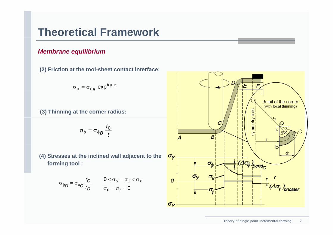
Theoretical FrameworkMembrane equilibrium
(2) Friction at the tool-sheet contact interface:
ϕμφφ σ=σ kB expφφ B
(3) Thinning at the corner radius:
tt
B0
φφ σ=σ
(4) Stresses at the inclined wall adjacent to the forming tool :
D
CCD r
rφφ σ=σ
0
0 1
=σ=σ
σ<σ=σ<
θ
φ
t
Y
Theory of single point incremental forming 7
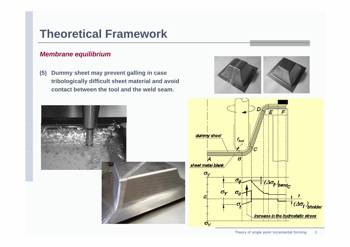
Theoretical FrameworkMembrane equilibrium
(5) Dummy sheet may prevent galling in case tribologically difficult sheet material and avoid contact between the tool and the weld seam.
Theory of single point incremental forming 8
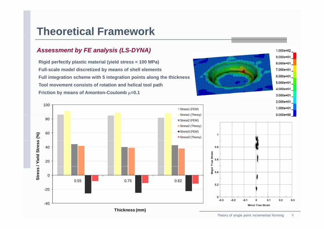
Theoretical FrameworkAssessment by FE analysis (LS-DYNA)
Rigid perfectly plastic material (yield stress = 100 MPa)Rigid perfectly plastic material (yield stress = 100 MPa)Full-scale model discretized by means of shell elementsFull integration scheme with 5 integration points along the thicknessTool movement consists of rotation and helical tool pathFriction by means of Amonton-Coulomb μ=0.1
100Stress1 (FEM)
Stress1 (Theory)
60
80
s (%
)
Stress1 (Theory)
Stress2 (FEM)
Stress2 (Theory)
Stress3 (FEM)
Stress3 (Theory)
20
40
/ Yie
ld S
tres
s
-20
00.55 0.75 0.82St
ress
Theory of single point incremental forming 9
-40
Thickness (mm)
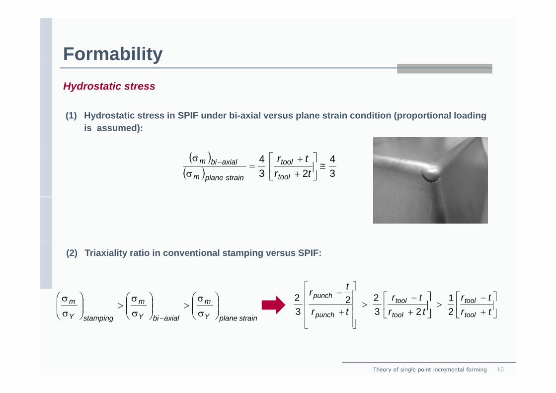
FormabilityyHydrostatic stress
(1) Hydrostatic stress in SPIF under bi-axial versus plane strain condition (proportional loading is assumed):
( )( )( ) 3
423
4≅⎥
⎦
⎤⎢⎣
⎡++
=σ
σ −
trtr
tool
tool
strainplanem
axialbim
(2) Triaxiality ratio in conventional stamping versus SPIF:
⎤⎡ t
⇔⎟⎟⎠
⎞⎜⎜⎝
⎛σσ
>⎟⎟⎠
⎞⎜⎜⎝
⎛σσ
>⎟⎟⎠
⎞⎜⎜⎝
⎛σσ
− strainplaneY
m
axialbiY
m
stampingY
m ⎥⎦
⎤⎢⎣
⎡+−
>⎥⎦
⎤⎢⎣
⎡+−
>
⎥⎥⎥⎥
⎦
⎤
⎢⎢⎢⎢
⎣
⎡
+
−
trtr
trtr
tr
tr
tool
tool
tool
tool
punch
punch
21
2322
32
Theory of single point incremental forming 10
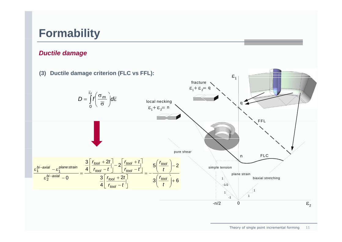
FormabilityyDuctile damage
ε1fracture
1ε + ε =2q
(3) Ductile damage criterion (FLC vs FFL):
⎞⎛εf
local necking
1ε + ε =2 nq
FFL
ε⎟⎠
⎞⎜⎝
⎛σ
σ= ∫
ε
dfDf
m
0
FFL
pure shear
simple tension
FLC
plane strain
n
25
23
22
43
011
⎞⎛
−⎟⎟⎠
⎞⎜⎜⎝
⎛
−=⎤⎡
⎥⎦
⎤⎢⎣
⎡−+
−⎥⎦
⎤⎢⎣
⎡−
+
=ε−ε −
rt
r
ttrtr
trtr tool
tool
tool
tool
tool
axialbi
strainplaneaxialbi
ε0-n/2
1
1-1
11
-1/2
biaxial stretching6324302 +⎟⎟
⎠
⎞⎜⎜⎝
⎛⎥⎦
⎤⎢⎣
⎡−
+−ε −
tr
trtr tool
tool
toolaxialbi
ε0-n/2 2
Theory of single point incremental forming 11
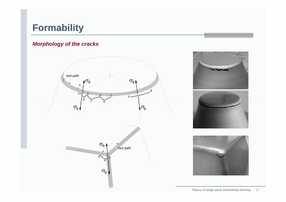
FormabilityyMorphology of the cracks
tool path
o
a
b
c
d
e
f
σφδ
φσ
o
g
c e
σφ φσ
σφt l th
o
σ
φtool path
ed
Theory of single point incremental forming 12
σφ
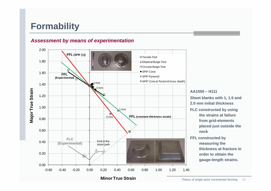
FormabilityyAssessment by means of experimentation
2.00
1.60
1.80Tensile Test
Elliptical Bulge Test
Circular Bulge Test
SPIF Cone
FFL (SPIF [1])
FFL
AA1050 – H111
1 mm
2 mm
1 20
1.40
1.60SPIF Pyramid
SPIF Cone & Pyramid (max. depth)
rain
FFL(Experimental)
Sheet blanks with 1, 1.5 and 2.0 mm initial thicknessFLC constructed by using
the strains at failure 1 mm
2 mm
1.00
1.20
ajor
True
Str
FFL (constant thickness strain)from grid-elements placed just outside the neck
FFL constructed by
2 mm
0.60
0.80
Ma FFL (constant thickness strain)
FLC FFL constructed by measuring the thickness at fracture in order to obtain the gauge-length strains.
0.20
0.40 Kink in the strain path
FLC(Experimental)
Theory of single point incremental forming 13
gauge length strains.0.00
-0.60 -0.40 -0.20 0.00 0.20 0.40 0.60 0.80 1.00 1.20 1.40
MinorTrue Strain
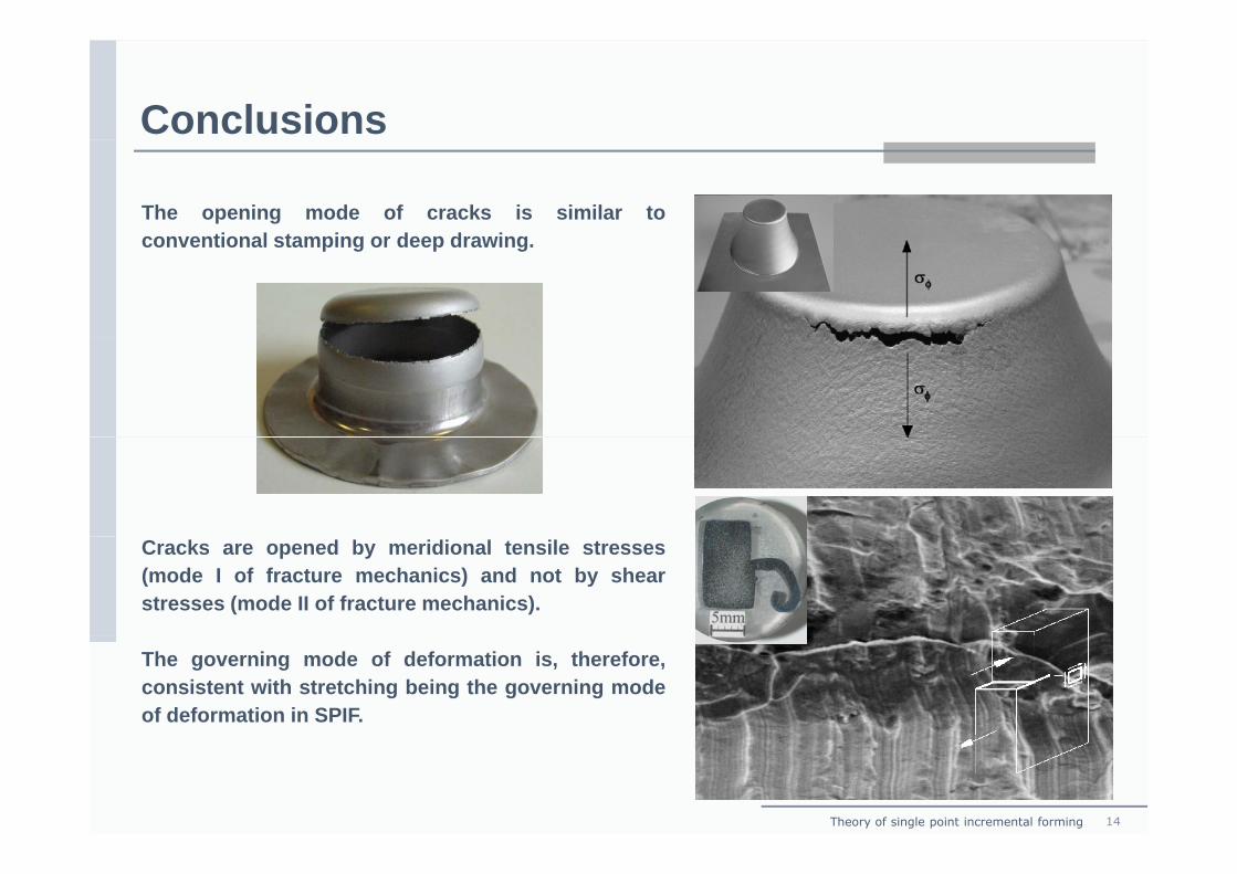
Conclusions
The opening mode of cracks is similar toconventional stamping or deep drawingconventional stamping or deep drawing.
Cracks are opened by meridional tensile stresses(mode I of fracture mechanics) and not by shearstresses (mode II of fracture mechanics).
The governing mode of deformation is, therefore,consistent with stretching being the governing modeof deformation in SPIF.
Theory of single point incremental forming 14
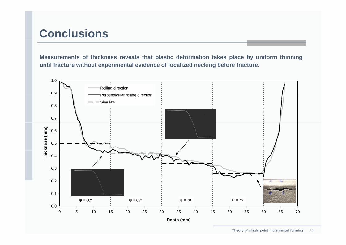
Conclusions
Measurements of thickness reveals that plastic deformation takes place by uniform thinninguntil fracture without experimental evidence of localized necking before fracture.p g
0.9
1.0
Rolling direction
Perpendicular rolling direction
0.7
0.8
Perpendicular rolling direction
Sine law
0.5
0.6
knes
s (m
m)
0.3
0.4Thic
0 0
0.1
0.2
ψ = 65º ψ = 70º ψ = 75ºψ = 60º
Theory of single point incremental forming 15
0.00 5 10 15 20 25 30 35 40 45 50 55 60 65 70
Depth (mm)
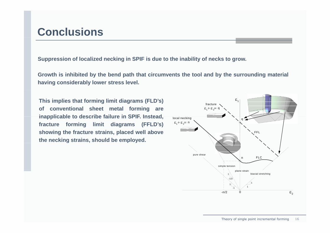
Conclusions
Suppression of localized necking in SPIF is due to the inability of necks to grow.
Growth is inhibited by the bend path that circumvents the tool and by the surrounding materialhaving considerably lower stress level.
ε1fracture
1ε + ε =2 q
This implies that forming limit diagrams (FLD’s)of conventional sheet metal forming areinapplicable to describe failure in SPIF Instead local necking
1ε + ε =2 nq
FFL
inapplicable to describe failure in SPIF. Instead,fracture forming limit diagrams (FFLD’s)showing the fracture strains, placed well abovethe necking strains, should be employed.
pure shear
simple tension
FLCn
g y
ε0-n/2
1
1-1
11
-1/2
2
biaxial stretchingplane strain
Theory of single point incremental forming 16
Acknowledgementsg
The support provided by Prof. Anthony G. Akins during the investigation is greatlyacknowledged by the authors.g y
Theory of single point incremental forming 17