ej5101 - incremental-encoder-interface - download - beckhoff
TRANSCRIPT
Documentation | EN
EJ5101Incremental-Encoder-Interface
2021-10-05 | Version: 1.4

Table of contents
EJ5101 3Version: 1.4
Table of contents1 Foreword .................................................................................................................................................... 5
1.1 Notes on the documentation.............................................................................................................. 51.2 Safety instructions ............................................................................................................................. 61.3 Intended use...................................................................................................................................... 71.4 Signal distribution board .................................................................................................................... 71.5 Documentation issue status .............................................................................................................. 71.6 Guide through documentation ........................................................................................................... 81.7 Marking of EtherCAT plug-in modules............................................................................................... 8
1.7.1 Beckhoff Identification Code (BIC)................................................................................... 111.7.2 Electronic access to the BIC (eBIC) ................................................................................ 131.7.3 Certificates....................................................................................................................... 15
2 System overview ..................................................................................................................................... 16
3 EJ5101 - Product description ................................................................................................................. 173.1 Introduction...................................................................................................................................... 173.2 Technical data ................................................................................................................................. 183.3 Level on interface ............................................................................................................................ 193.4 Pinout .............................................................................................................................................. 203.5 LEDs................................................................................................................................................ 22
4 Installation of EJ modules ...................................................................................................................... 234.1 Power supply for the EtherCAT plug-in modules............................................................................. 234.2 EJxxxx - dimensions........................................................................................................................ 254.3 Installation positions and minimum distances ................................................................................. 26
4.3.1 Minimum distances for ensuring installability................................................................... 264.3.2 Installation positions ........................................................................................................ 27
4.4 Codings ........................................................................................................................................... 294.4.1 Color coding..................................................................................................................... 294.4.2 Mechanical position coding.............................................................................................. 30
4.5 Installation on the signal distribution board ..................................................................................... 314.6 Extension options ............................................................................................................................ 33
4.6.1 Using placeholder modules for unused slots ................................................................... 334.6.2 Linking with EtherCAT Terminals and EtherCAT Box modules via an Ethernet/EtherCAT
connection ....................................................................................................................... 344.7 IPC integration................................................................................................................................. 354.8 Disassembly of the signal distribution board ................................................................................... 374.9 Disposal ........................................................................................................................................... 37
5 EtherCAT basics...................................................................................................................................... 38
6 Commissioning........................................................................................................................................ 396.1 Reference to documentation EL5101 .............................................................................................. 396.2 EJ5101 - object description and parameterization .......................................................................... 39
6.2.1 Restore object.................................................................................................................. 396.2.2 Configuration data ........................................................................................................... 406.2.3 Input data......................................................................................................................... 426.2.4 Output data ...................................................................................................................... 44

Table of contents
EJ51014 Version: 1.4
6.2.5 Information and diagnostic data / channel-specific.......................................................... 446.2.6 Standard objects.............................................................................................................. 44
7 Appendix .................................................................................................................................................. 557.1 Support and Service ........................................................................................................................ 55

Foreword
EJ5101 5Version: 1.4
1 Foreword
1.1 Notes on the documentation
Intended audience
This description is only intended for the use of trained specialists in control and automation engineering whoare familiar with the applicable national standards.It is essential that the documentation and the following notes and explanations are followed when installingand commissioning these components.It is the duty of the technical personnel to use the documentation published at the respective time of eachinstallation and commissioning.
The responsible staff must ensure that the application or use of the products described satisfy all therequirements for safety, including all the relevant laws, regulations, guidelines and standards.
Disclaimer
The documentation has been prepared with care. The products described are, however, constantly underdevelopment.
We reserve the right to revise and change the documentation at any time and without prior announcement.
No claims for the modification of products that have already been supplied may be made on the basis of thedata, diagrams and descriptions in this documentation.
Trademarks
Beckhoff®, TwinCAT®, TwinCAT/BSD®, TC/BSD®, EtherCAT®, EtherCAT G®, EtherCAT G10®, EtherCAT P®,Safety over EtherCAT®, TwinSAFE®, XFC®, XTS® and XPlanar® are registered trademarks of and licensed byBeckhoff Automation GmbH. Other designations used in this publication may be trademarks whose use bythird parties for their own purposes could violate the rights of the owners.
Patent Pending
The EtherCAT Technology is covered, including but not limited to the following patent applications andpatents: EP1590927, EP1789857, EP1456722, EP2137893, DE102015105702 with correspondingapplications or registrations in various other countries.
EtherCAT® is registered trademark and patented technology, licensed by Beckhoff Automation GmbH,Germany.
Copyright
© Beckhoff Automation GmbH & Co. KG, Germany.The reproduction, distribution and utilization of this document as well as the communication of its contents toothers without express authorization are prohibited.Offenders will be held liable for the payment of damages. All rights reserved in the event of the grant of apatent, utility model or design.

Foreword
EJ51016 Version: 1.4
1.2 Safety instructions
Safety regulations
Please note the following safety instructions and explanations!Product-specific safety instructions can be found on following pages or in the areas mounting, wiring,commissioning etc.
Exclusion of liability
All the components are supplied in particular hardware and software configurations appropriate for theapplication. Modifications to hardware or software configurations other than those described in thedocumentation are not permitted, and nullify the liability of Beckhoff Automation GmbH & Co. KG.
Personnel qualification
This description is only intended for trained specialists in control, automation and drive engineering who arefamiliar with the applicable national standards.
Description of instructions
In this documentation the following instructions are used. These instructions must be read carefully and followed without fail!
DANGERSerious risk of injury!Failure to follow this safety instruction directly endangers the life and health of persons.
WARNINGRisk of injury!Failure to follow this safety instruction endangers the life and health of persons.
CAUTIONPersonal injuries!Failure to follow this safety instruction can lead to injuries to persons.
NOTEDamage to environment/equipment or data lossFailure to follow this instruction can lead to environmental damage, equipment damage or data loss.
Tip or pointerThis symbol indicates information that contributes to better understanding.

Foreword
EJ5101 7Version: 1.4
1.3 Intended use WARNING
Caution - Risk of injury!EJ components may only be used for the purposes described below!
1.4 Signal distribution boardNOTE
Signal distribution boardMake sure that the EtherCAT plug-in modules are used only on a signal distribution board that has beendeveloped and manufactured in accordance with the Design Guide.
1.5 Documentation issue statusVersion Comment1.4 • Update chapter Marking of EtherCAT plug-in modules
• Update Technical Data• Chapter Disposal added• Update structure
1.3 • New title page• Update chapter Connection• Chapters Basics communication, TwinCAT Quick Start , TwinCAT development
environment and General Notes - EtherCAT Slave Application replaced byreferences in the chapter Guide through the documentation
• Chapter EJ5101 - Object description and parameterization added• Update revision status• Structural update
1.2 • Note Signal Distribution Board added• Chapter Version identification of EtherCAT devices replaced by Marking of
EtherCAT plug-in modules• Update Technical data• Update chapter Connection• Update revision status
1.1 • Notes on routing and installation added1.0 • First publication EJ5101

Foreword
EJ51018 Version: 1.4
1.6 Guide through documentationNOTE
Further components of documentationThe documentations named in the following table are further components of the completedocumentation. These documentations are required for the use of EtherCAT plug-in mod-ules.
No. Title Description[1] EtherCAT System Documentation • System overview
• EtherCAT basics• Cable redundancy• Hot Connect• Distributed Clocks• Configuration of EtherCAT-Components
[2] Infrastructure for EtherCAT/Ethernet • Technical recommendations and notes fordesign, implementation an testing
[3] Design GuideSignal-Distribution-Board forstandard EtherCAT plug-in modules
Requirements for the design of a Signal-Distribution-Board for standard EtherCAT plug-inmodules• Backplane mounting guidelines• Module placement• Routing guidelines
[4] Documentation of the corresponding terminalELxxxx
• Notes on the principle of operation and• Descriptions for configuration and
parameterizationare transferable to the corresponding ModuleEJxxxx (s. note on documentation of ELxxxx[} 39]).
1.7 Marking of EtherCAT plug-in modules
Designation
A Beckhoff EtherCAT device has a 14-digit technical designation, made up as follows (e.g.EJ1008-0000-0017)
• Order identifier◦ family key: EJ◦ product designation: The first digit of product designation is used for assignment to a product
group (e.g. EJ2xxx = digital output module).◦ Version number: The four digit version number identifies different product variants.
• Revision number:It is incremented when changes are made to the product.
The Order identifier and the revision number are printed on the side of EtherCAT plug-in modules (s.following illustration (A and B).
Foreword
EJ5101 9Version: 1.4
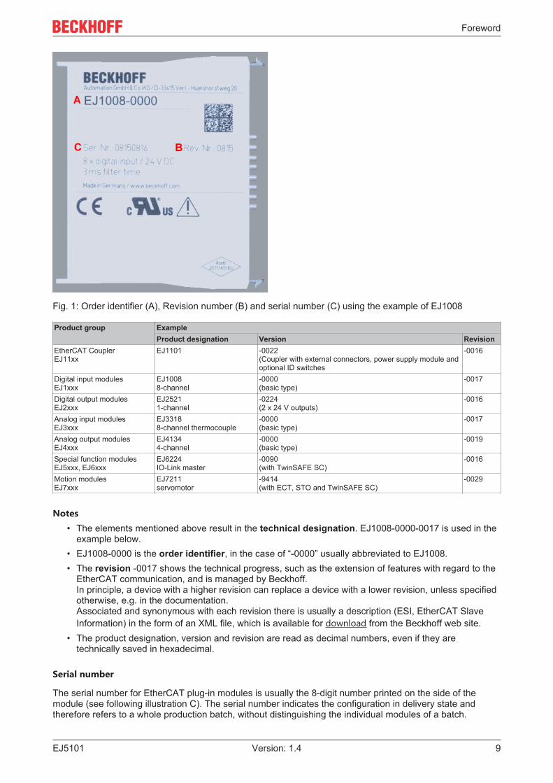
Fig. 1: Order identifier (A), Revision number (B) and serial number (C) using the example of EJ1008
Product group ExampleProduct designation Version Revision
EtherCAT CouplerEJ11xx
EJ1101 -0022(Coupler with external connectors, power supply module andoptional ID switches
-0016
Digital input modulesEJ1xxx
EJ10088-channel
-0000(basic type)
-0017
Digital output modulesEJ2xxx
EJ25211-channel
-0224(2 x 24 V outputs)
-0016
Analog input modulesEJ3xxx
EJ33188-channel thermocouple
-0000(basic type)
-0017
Analog output modulesEJ4xxx
EJ41344-channel
-0000(basic type)
-0019
Special function modulesEJ5xxx, EJ6xxx
EJ6224IO-Link master
-0090(with TwinSAFE SC)
-0016
Motion modulesEJ7xxx
EJ7211servomotor
-9414(with ECT, STO and TwinSAFE SC)
-0029
Notes• The elements mentioned above result in the technical designation. EJ1008-0000-0017 is used in the
example below.• EJ1008-0000 is the order identifier, in the case of “-0000” usually abbreviated to EJ1008.• The revision -0017 shows the technical progress, such as the extension of features with regard to the
EtherCAT communication, and is managed by Beckhoff.In principle, a device with a higher revision can replace a device with a lower revision, unless specifiedotherwise, e.g. in the documentation.Associated and synonymous with each revision there is usually a description (ESI, EtherCAT SlaveInformation) in the form of an XML file, which is available for download from the Beckhoff web site.
• The product designation, version and revision are read as decimal numbers, even if they aretechnically saved in hexadecimal.
Serial number
The serial number for EtherCAT plug-in modules is usually the 8-digit number printed on the side of themodule (see following illustration C). The serial number indicates the configuration in delivery state andtherefore refers to a whole production batch, without distinguishing the individual modules of a batch.

Foreword
EJ510110 Version: 1.4
Fig. 2: Order identifier (A), revision number (B) and serial number (C) using the example of EJ1008
Serial number Example serial number: 08 15 08 16KK - week of production (CW, calendar week) 08 - week of production: 08YY - year of production 15 - year of production: 2015FF - firmware version 08 -f irmware version: 08HH - hardware version 16 - hardware version: 16

Foreword
EJ5101 11Version: 1.4
1.7.1 Beckhoff Identification Code (BIC)The Beckhoff Identification Code (BIC) is increasingly being applied to Beckhoff products to uniquely identifythe product. The BIC is represented as a Data Matrix Code (DMC, code scheme ECC200), the content isbased on the ANSI standard MH10.8.2-2016.
Fig. 3: BIC as data matrix code (DMC, code scheme ECC200)
The BIC will be introduced step by step across all product groups.
Depending on the product, it can be found in the following places:
• on the packaging unit• directly on the product (if space suffices)• on the packaging unit and the product
The BIC is machine-readable and contains information that can also be used by the customer for handlingand product management.
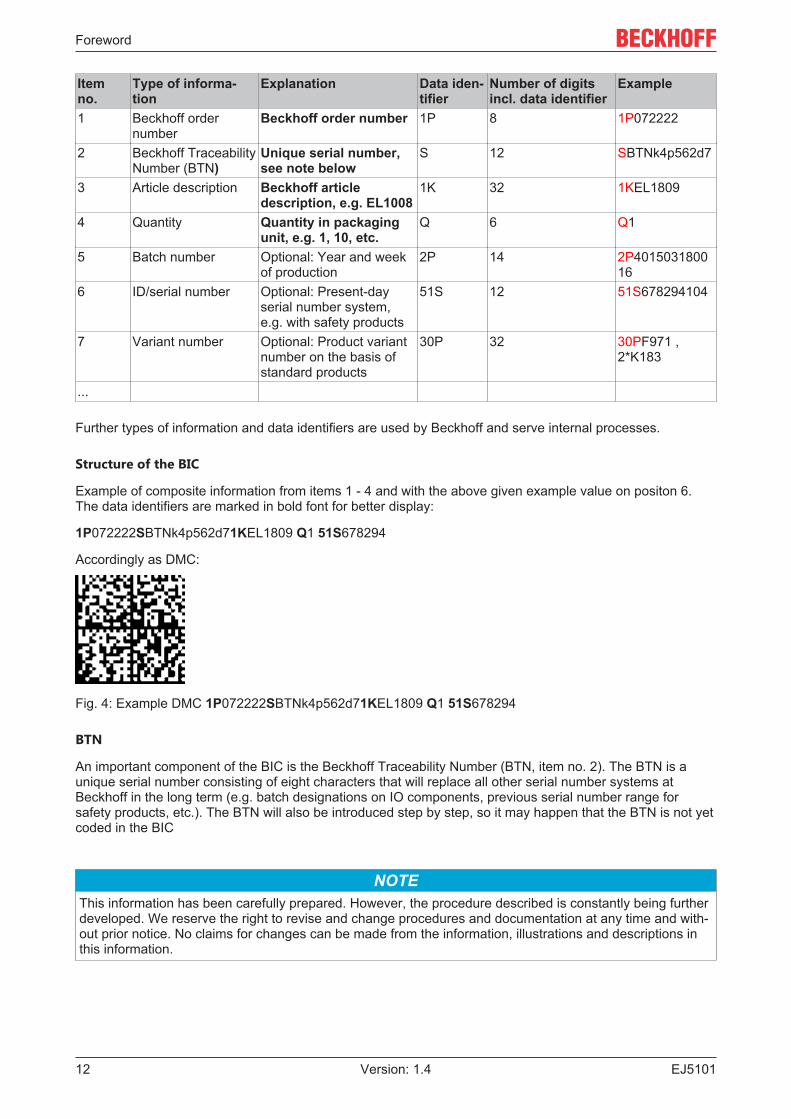
Each piece of information can be uniquely identified using the so-called data identifier (ANSIMH10.8.2-2016). The data identifier is followed by a character string. Both together have a maximum lengthaccording to the table below. If the information is shorter, it shall be replaced by spaces. The data underpositions 1-4 are always available.
The following information is contained:
Foreword
EJ510112 Version: 1.4
Itemno.
Type of informa-tion
Explanation Data iden-tifier
Number of digitsincl. data identifier
Example
1 Beckhoff ordernumber
Beckhoff order number 1P 8 1P072222
2 Beckhoff TraceabilityNumber (BTN)
Unique serial number,see note below
S 12 SBTNk4p562d7
3 Article description Beckhoff articledescription, e.g. EL1008
1K 32 1KEL1809
4 Quantity Quantity in packagingunit, e.g. 1, 10, etc.
Q 6 Q1
5 Batch number Optional: Year and weekof production
2P 14 2P401503180016
6 ID/serial number Optional: Present-dayserial number system,e.g. with safety products
51S 12 51S678294104
7 Variant number Optional: Product variantnumber on the basis ofstandard products
30P 32 30PF971 ,2*K183
...
Further types of information and data identifiers are used by Beckhoff and serve internal processes.
Structure of the BIC
Example of composite information from items 1 - 4 and with the above given example value on positon 6.The data identifiers are marked in bold font for better display:
1P072222SBTNk4p562d71KEL1809 Q1 51S678294
Accordingly as DMC:
Fig. 4: Example DMC 1P072222SBTNk4p562d71KEL1809 Q1 51S678294
BTN
An important component of the BIC is the Beckhoff Traceability Number (BTN, item no. 2). The BTN is aunique serial number consisting of eight characters that will replace all other serial number systems atBeckhoff in the long term (e.g. batch designations on IO components, previous serial number range forsafety products, etc.). The BTN will also be introduced step by step, so it may happen that the BTN is not yetcoded in the BIC
NOTEThis information has been carefully prepared. However, the procedure described is constantly being furtherdeveloped. We reserve the right to revise and change procedures and documentation at any time and with-out prior notice. No claims for changes can be made from the information, illustrations and descriptions inthis information.

Foreword
EJ5101 13Version: 1.4
1.7.2 Electronic access to the BIC (eBIC)
Electronic BIC (eBIC)
The Beckhoff Identification Code (BIC) is applied to the outside of Beckhoff products in a visible place. Ifpossible, it should also be electronically readable.
Decisive for the electronic readout is the interface via which the product can be electronically addressed.
K-bus devices (IP20, IP67)
Currently, no electronic storage and readout is planned for these devices.
EtherCAT devices (IP20, IP67)
All Beckhoff EtherCAT devices have a so-called ESI-EEPROM, which contains the EtherCAT identity withthe revision number. Stored in it is the EtherCAT slave information, also colloquially known as ESI/XMLconfiguration file for the EtherCAT master. See the corresponding chapter in the EtherCAT system manual(Link) for the relationships.
The eBIC is also stored in the ESI‑EEPROM. The eBIC was introduced into the Beckhoff I/O production(terminals, boxes) from 2020; widespread implementation is expected in 2021.
The user can electronically access the eBIC (if existent) as follows:
• With all EtherCAT devices, the EtherCAT master (TwinCAT) can read the eBIC from the ESI‑EEPROM◦ From TwinCAT 4024.11, the eBIC can be displayed in the online view.◦ To do this,
check the checkbox "Show Beckhoff Identification Code (BIC)" underEtherCAT → Advanced Settings → Diagnostics:
◦ The BTN and its contents are then displayed:
◦ Note: as can be seen in the illustration, the production data HW version, FW version andproduction date, which have been programmed since 2012, can also be displayed with "ShowProduction Info".
• In the case of EtherCAT devices with CoE directory, the object 0x10E2:01 can additionally by used todisplay the device's own eBIC; the PLC can also simply access the information here:
Foreword
EJ510114 Version: 1.4
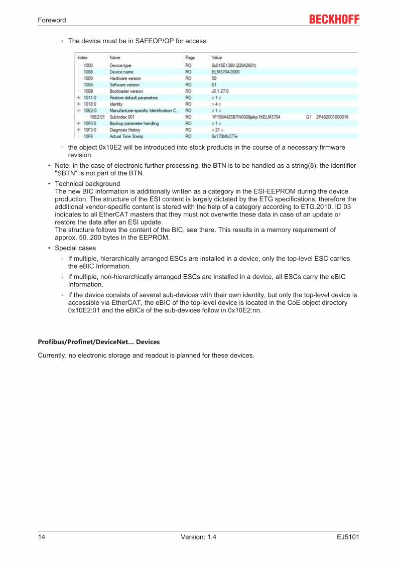
◦ The device must be in SAFEOP/OP for access:
◦ the object 0x10E2 will be introduced into stock products in the course of a necessary firmwarerevision.
• Note: in the case of electronic further processing, the BTN is to be handled as a string(8); the identifier"SBTN" is not part of the BTN.
• Technical backgroundThe new BIC information is additionally written as a category in the ESI‑EEPROM during the deviceproduction. The structure of the ESI content is largely dictated by the ETG specifications, therefore theadditional vendor-specific content is stored with the help of a category according to ETG.2010. ID 03indicates to all EtherCAT masters that they must not overwrite these data in case of an update orrestore the data after an ESI update. The structure follows the content of the BIC, see there. This results in a memory requirement ofapprox. 50..200 bytes in the EEPROM.
• Special cases◦ If multiple, hierarchically arranged ESCs are installed in a device, only the top-level ESC carries
the eBIC Information.◦ If multiple, non-hierarchically arranged ESCs are installed in a device, all ESCs carry the eBIC
Information.◦ If the device consists of several sub-devices with their own identity, but only the top-level device is
accessible via EtherCAT, the eBIC of the top-level device is located in the CoE object directory0x10E2:01 and the eBICs of the sub-devices follow in 0x10E2:nn.
Profibus/Profinet/DeviceNet… Devices
Currently, no electronic storage and readout is planned for these devices.
Foreword
EJ5101 15Version: 1.4
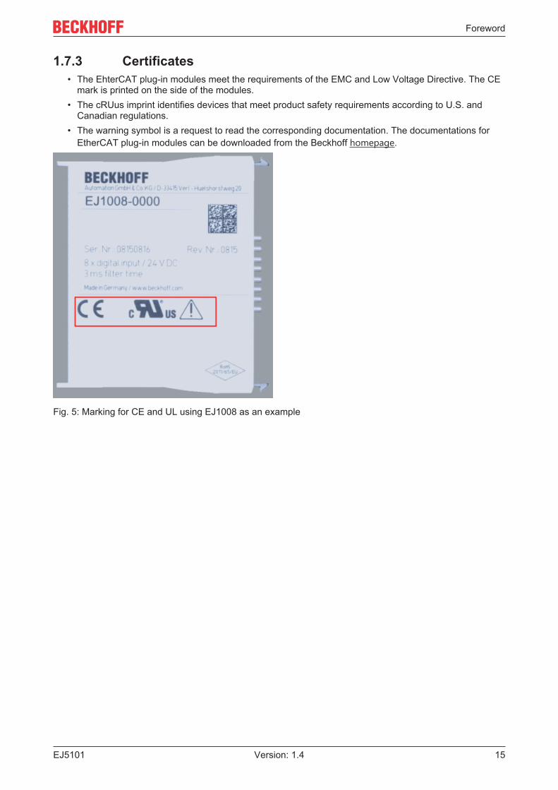
1.7.3 Certificates• The EhterCAT plug-in modules meet the requirements of the EMC and Low Voltage Directive. The CE
mark is printed on the side of the modules.• The cRUus imprint identifies devices that meet product safety requirements according to U.S. and
Canadian regulations.• The warning symbol is a request to read the corresponding documentation. The documentations for
EtherCAT plug-in modules can be downloaded from the Beckhoff homepage.
Fig. 5: Marking for CE and UL using EJ1008 as an example

System overview
EJ510116 Version: 1.4
2 System overviewElectronically, the EJxxxx EtherCAT plug-in modules are based on the EtherCAT I/O system. The EJ systemconsists of the signal distribution board and EtherCAT plug-in modules. It is also possible to connect an IPCto the EJ system.The EJ system is suitable for mass production applications, applications with small footprint and applicationsrequiring a low total weight.The machine complexity can be extended by means of the following:
• reserve slots,• the use of placeholder modules,• linking of EtherCAT Terminals and EtherCAT Boxes via an EtherCAT connection.
The following diagram illustrates an EJ system. The components shown are schematic, to illustrate thefunctionality.
Fig. 6: EJ system sample
Signal distribution board
The signal distribution board distributes the signals and the power supply to individual application-specificplug connectors, in order to connect the controller to further machine modules. Using pre-assembled cableharnesses avoids the need for time-consuming connection of individual wires. Coded components reducethe unit costs and the risk of miswiring.Beckhoff offers development of signal distribution boards as an engineering service. Customers have theoption to develop their own signal distribution board, based on the design guide.
EtherCAT plug-in modules
Similar to the EtherCAT terminal system, a module strand consists of a Bus Coupler and I/O modules.Almost all of the EtherCAT Terminals can also be manufactured in the EJ design as EtherCAT plug-inmodules. The EJ modules are directly attached to the signal distribution board. The communication, signaldistribution and supply take place via the contact pins at the rear of the modules and the PCB tracks of thesignal distribution board. The coding pins at the rear serve as mechanical protection against incorrectconnection. Color coding on the housing facilitates distinguishing of the modules.
EJ5101 - Product description
EJ5101 17Version: 1.4
3 EJ5101 - Product description
3.1 Introduction
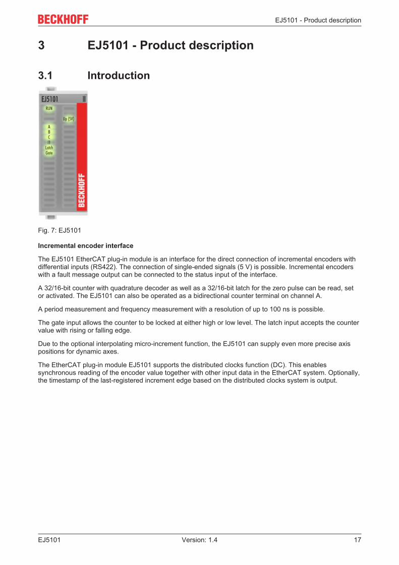
Fig. 7: EJ5101
Incremental encoder interface
The EJ5101 EtherCAT plug-in module is an interface for the direct connection of incremental encoders withdifferential inputs (RS422). The connection of single-ended signals (5 V) is possible. Incremental encoderswith a fault message output can be connected to the status input of the interface.
A 32/16-bit counter with quadrature decoder as well as a 32/16-bit latch for the zero pulse can be read, setor activated. The EJ5101 can also be operated as a bidirectional counter terminal on channel A.
A period measurement and frequency measurement with a resolution of up to 100 ns is possible.
The gate input allows the counter to be locked at either high or low level. The latch input accepts the countervalue with rising or falling edge.
Due to the optional interpolating micro-increment function, the EJ5101 can supply even more precise axispositions for dynamic axes.
The EtherCAT plug-in module EJ5101 supports the distributed clocks function (DC). This enablessynchronous reading of the encoder value together with other input data in the EtherCAT system. Optionally,the timestamp of the last-registered increment edge based on the distributed clocks system is output.
EJ5101 - Product description
EJ510118 Version: 1.4
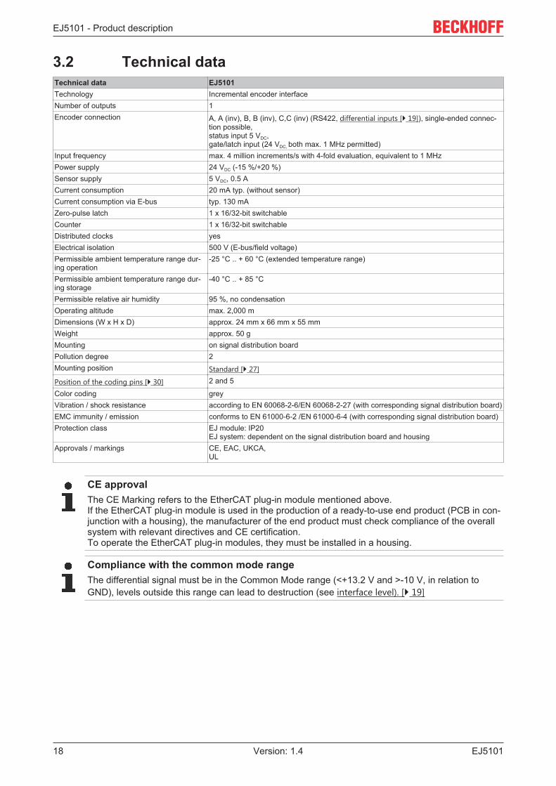
3.2 Technical dataTechnical data EJ5101Technology Incremental encoder interfaceNumber of outputs 1Encoder connection A, A (inv), B, B (inv), C,C (inv) (RS422, differential inputs [} 19]), single-ended connec-
tion possible, status input 5 VDC,gate/latch input (24 VDC, both max. 1 MHz permitted)
Input frequency max. 4 million increments/s with 4-fold evaluation, equivalent to 1 MHzPower supply 24 VDC (-15 %/+20 %)Sensor supply 5 VDC, 0.5 ACurrent consumption 20 mA typ. (without sensor)Current consumption via E-bus typ. 130 mAZero-pulse latch 1 x 16/32-bit switchableCounter 1 x 16/32-bit switchableDistributed clocks yesElectrical isolation 500 V (E-bus/field voltage)Permissible ambient temperature range dur-ing operation
-25 °C .. + 60 °C (extended temperature range)
Permissible ambient temperature range dur-ing storage
-40 °C .. + 85 °C
Permissible relative air humidity 95 %, no condensationOperating altitude max. 2,000 mDimensions (W x H x D) approx. 24 mm x 66 mm x 55 mmWeight approx. 50 gMounting on signal distribution boardPollution degree 2Mounting position Standard [} 27]
Position of the coding pins [} 30] 2 and 5
Color coding greyVibration / shock resistance according to EN 60068-2-6/EN 60068-2-27 (with corresponding signal distribution board)EMC immunity / emission conforms to EN 61000-6-2 /EN 61000-6-4 (with corresponding signal distribution board)Protection class EJ module: IP20
EJ system: dependent on the signal distribution board and housingApprovals / markings CE, EAC, UKCA,
UL
CE approvalThe CE Marking refers to the EtherCAT plug-in module mentioned above.If the EtherCAT plug-in module is used in the production of a ready-to-use end product (PCB in con-junction with a housing), the manufacturer of the end product must check compliance of the overallsystem with relevant directives and CE certification.To operate the EtherCAT plug-in modules, they must be installed in a housing.
Compliance with the common mode rangeThe differential signal must be in the Common Mode range (<+13.2 V and >-10 V, in relation toGND), levels outside this range can lead to destruction (see interface level). [} 19]
EJ5101 - Product description
EJ5101 19Version: 1.4
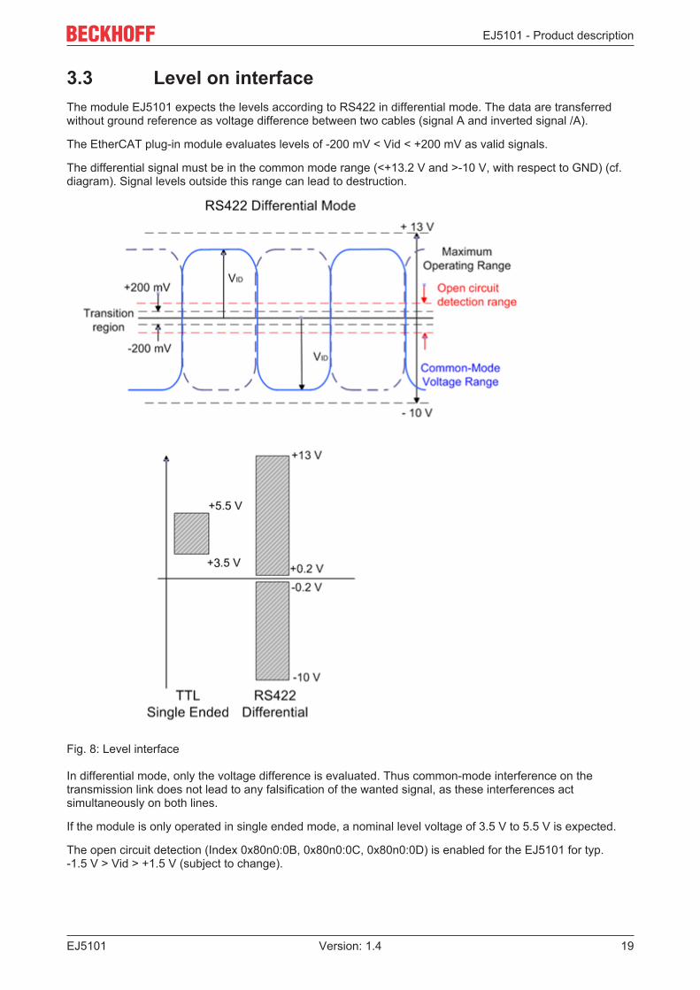
3.3 Level on interfaceThe module EJ5101 expects the levels according to RS422 in differential mode. The data are transferredwithout ground reference as voltage difference between two cables (signal A and inverted signal /A).
The EtherCAT plug-in module evaluates levels of -200 mV < Vid < +200 mV as valid signals.
The differential signal must be in the common mode range (<+13.2 V and >-10 V, with respect to GND) (cf.diagram). Signal levels outside this range can lead to destruction.
Fig. 8: Level interface
In differential mode, only the voltage difference is evaluated. Thus common-mode interference on thetransmission link does not lead to any falsification of the wanted signal, as these interferences actsimultaneously on both lines.
If the module is only operated in single ended mode, a nominal level voltage of 3.5 V to 5.5 V is expected.
The open circuit detection (Index 0x80n0:0B, 0x80n0:0C, 0x80n0:0D) is enabled for the EJ5101 for typ.-1.5 V > Vid > +1.5 V (subject to change).

EJ5101 - Product description
EJ510120 Version: 1.4
3.4 Pinout
Fig. 9: EJ5101 - Pinout
The PCB footprint can be downloaded from the Beckhoff homepage
NOTEDamage to devices possible!• The pins named with “NC” must not be connected.
• Before installation and commissioning read the chapters Installation of EJ modules[} 23] and Commissioning [} 39]!
The following points should be considered during design phase and installation:

EJ5101 - Product description
EJ5101 21Version: 1.4
Notes for routing and installation• The SSI information (Clock and Data) are transmitted as differential signals. To ensure a good
EMC immunity, also for long distances, shielded cables with twisted pair conductors should beused.
ð The cable shield should be connected to earth at both channel ends and the two end de-vices should be always at the same reference potential.
ð When using externally shielded cables, particular care should be paid, not to damage or tointerrupt the shield itself.
ð Shield should be connected near by the connector.
ð Refer also to the corresponding notes of the sensor manufacturer!
• Refer to the guide lines in the design guide for the EtherCAT plug-in modules to ensure a properrouting of the differential signals!
• The value of each termination resistor should be equal to the cable characteristic impedance,typically 120 Ω for EIA-485 or RS-482 standard.
• Routing of the differential signals should be impedance controlled with typically 120 Ω forEIA-485 or RS-482 standard. Traces wide should be > 0.2 mm, the maximum ampacity need tobe taken into account.
• To improve the EMC immunity it may be helpful to connect the two signal channels on two differ-ent connectors
EJ5101 - Product description
EJ510122 Version: 1.4
3.5 LEDs
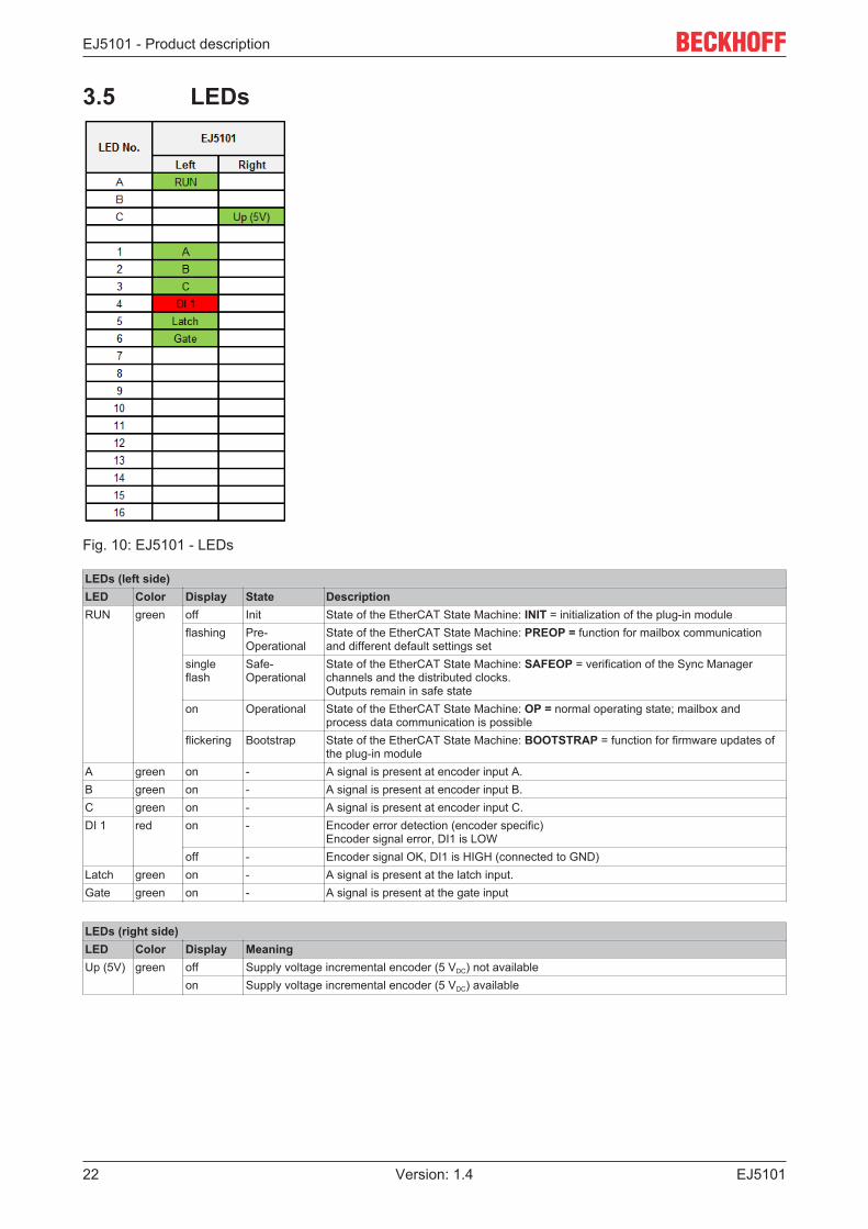
Fig. 10: EJ5101 - LEDs
LEDs (left side)LED Color Display State DescriptionRUN green off Init State of the EtherCAT State Machine: INIT = initialization of the plug-in module
flashing Pre-Operational
State of the EtherCAT State Machine: PREOP = function for mailbox communicationand different default settings set
singleflash
Safe-Operational
State of the EtherCAT State Machine: SAFEOP = verification of the Sync Managerchannels and the distributed clocks.Outputs remain in safe state
on Operational State of the EtherCAT State Machine: OP = normal operating state; mailbox andprocess data communication is possible
flickering Bootstrap State of the EtherCAT State Machine: BOOTSTRAP = function for firmware updates ofthe plug-in module
A green on - A signal is present at encoder input A.B green on - A signal is present at encoder input B.C green on - A signal is present at encoder input C.DI 1 red on - Encoder error detection (encoder specific)
Encoder signal error, DI1 is LOWoff - Encoder signal OK, DI1 is HIGH (connected to GND)
Latch green on - A signal is present at the latch input.Gate green on - A signal is present at the gate input
LEDs (right side)LED Color Display MeaningUp (5V) green off Supply voltage incremental encoder (5 VDC) not available
on Supply voltage incremental encoder (5 VDC) available

Installation of EJ modules
EJ5101 23Version: 1.4
4 Installation of EJ modules
4.1 Power supply for the EtherCAT plug-in modules WARNING
Power supplyA SELV/PELV power supply must be used to supply power for the EJ coupler and modules. Couplers andmodules have to be connected to SELV/PELV circuits exclusively.
The signal distribution board should have a power supply designed for the maximum possible current load ofthe module string. Information on the current required from the E-bus supply can be found for each modulein the respective documentation in section “Technical data”, online and in the catalog. The powerrequirement of the module string is displayed in the TwinCAT System Manager.
E-bus power supply with EJ1100 or EJ1101-0022 and EJ940x
The EJ1100 Bus Coupler supplies the connected EJ modules with the E-bus system voltage of 3.3 V. TheCoupler can accommodate a load up to 2.2 A. If a higher current is required, a combination of the couplerEJ1101-0022 and the power supply units EJ9400 (2.5 A) or EJ9404 (12 A) should be used. The EJ940xpower supply units can be used as additional supply modules in the module string.
Depending on the application, the following combinations for the E-bus supply are available:
Fig. 11: E-bus power supply with EJ1100 or EJ1101-0022 + EJ940x
In the EJ1101-0022 coupler, the RJ45 connectors and optional ID switches are external and can bepositioned anywhere on the signal distribution board, as required. This facilitates feeding through a housing.
The EJ940x power supply plug-in modules provide an optional reset function (see chapter Connection of thedocumentation for EJ9400 and EJ9404)
Installation of EJ modules
EJ510124 Version: 1.4
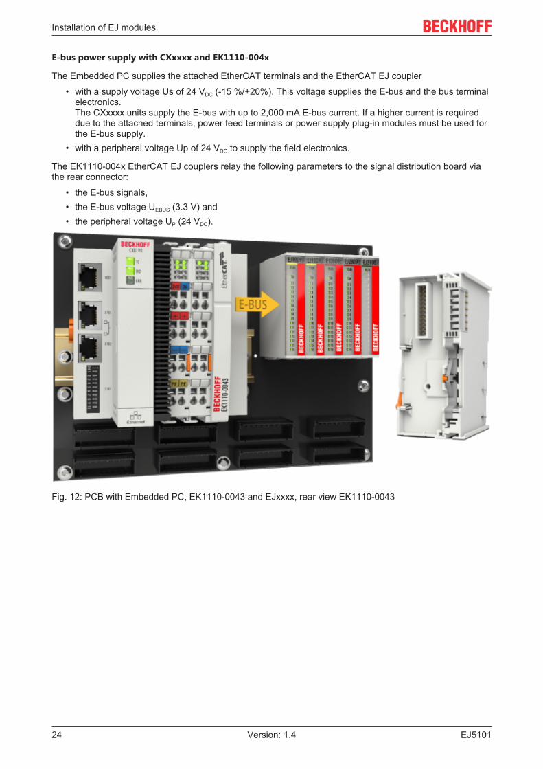
E-bus power supply with CXxxxx and EK1110-004x
The Embedded PC supplies the attached EtherCAT terminals and the EtherCAT EJ coupler
• with a supply voltage Us of 24 VDC (-15 %/+20%). This voltage supplies the E-bus and the bus terminalelectronics. The CXxxxx units supply the E-bus with up to 2,000 mA E-bus current. If a higher current is requireddue to the attached terminals, power feed terminals or power supply plug-in modules must be used forthe E-bus supply.
• with a peripheral voltage Up of 24 VDC to supply the field electronics.
The EK1110-004x EtherCAT EJ couplers relay the following parameters to the signal distribution board viathe rear connector:
• the E-bus signals,• the E-bus voltage UEBUS (3.3 V) and• the peripheral voltage UP (24 VDC).
Fig. 12: PCB with Embedded PC, EK1110-0043 and EJxxxx, rear view EK1110-0043
Installation of EJ modules
EJ5101 25Version: 1.4
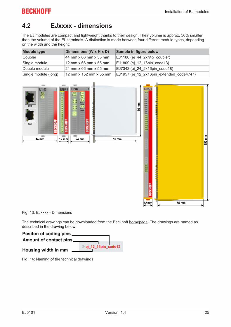
4.2 EJxxxx - dimensionsThe EJ modules are compact and lightweight thanks to their design. Their volume is approx. 50% smallerthan the volume of the EL terminals. A distinction is made between four different module types, dependingon the width and the height:
Module type Dimensions (W x H x D) Sample in figure belowCoupler 44 mm x 66 mm x 55 mm EJ1100 (ej_44_2xrj45_coupler)Single module 12 mm x 66 mm x 55 mm EJ1809 (ej_12_16pin_code13)Double module 24 mm x 66 mm x 55 mm EJ7342 (ej_24_2x16pin_code18)Single module (long) 12 mm x 152 mm x 55 mm EJ1957 (ej_12_2x16pin_extended_code4747)
Fig. 13: EJxxxx - Dimensions
The technical drawings can be downloaded from the Beckhoff homepage. The drawings are named asdescribed in the drawing below.
Fig. 14: Naming of the technical drawings

Installation of EJ modules
EJ510126 Version: 1.4
4.3 Installation positions and minimum distances
4.3.1 Minimum distances for ensuring installabilityNote the dimensions shown in the following diagram for the design of the signal distribution board to ensuresafe latching and simple assembly / disassembly of the modules.
Fig. 15: Mounting distances EJ module - PCB
Observing the reaching areaA minimum reaching area of 92 mm is required for assembly / disassembly, in order to be able toreach the mounting tabs with the fingers.Adherence to the recommended minimum distances for ventilation (see section Installation position[} 27]) ensures an adequate reaching area.
The signal distribution board must have a thickness of 1.6 mm and a minimum distance of 4 mm from themounting surface, in order to ensure latching of the modules on the board.
Installation of EJ modules
EJ5101 27Version: 1.4
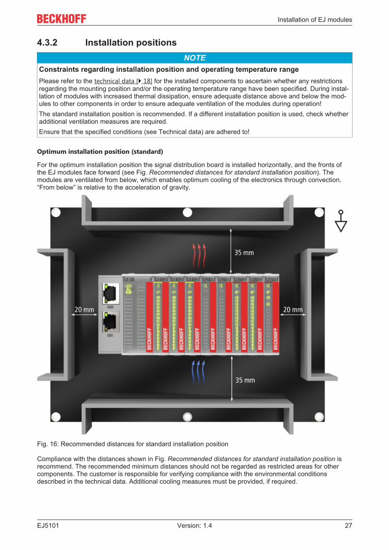
4.3.2 Installation positionsNOTE
Constraints regarding installation position and operating temperature rangePlease refer to the technical data [} 18] for the installed components to ascertain whether any restrictionsregarding the mounting position and/or the operating temperature range have been specified. During instal-lation of modules with increased thermal dissipation, ensure adequate distance above and below the mod-ules to other components in order to ensure adequate ventilation of the modules during operation!The standard installation position is recommended. If a different installation position is used, check whetheradditional ventilation measures are required.Ensure that the specified conditions (see Technical data) are adhered to!
Optimum installation position (standard)
For the optimum installation position the signal distribution board is installed horizontally, and the fronts ofthe EJ modules face forward (see Fig. Recommended distances for standard installation position). Themodules are ventilated from below, which enables optimum cooling of the electronics through convection.“From below” is relative to the acceleration of gravity.
Fig. 16: Recommended distances for standard installation position
Compliance with the distances shown in Fig. Recommended distances for standard installation position isrecommend. The recommended minimum distances should not be regarded as restricted areas for othercomponents. The customer is responsible for verifying compliance with the environmental conditionsdescribed in the technical data. Additional cooling measures must be provided, if required.
Installation of EJ modules
EJ510128 Version: 1.4
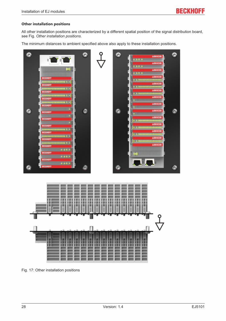
Other installation positions
All other installation positions are characterized by a different spatial position of the signal distribution board,see Fig. Other installation positions.
The minimum distances to ambient specified above also apply to these installation positions.
Fig. 17: Other installation positions

Installation of EJ modules
EJ5101 29Version: 1.4
4.4 Codings
4.4.1 Color coding
Fig. 18: EJ modules color code; sample: EJ1809
The EJ modules are color-coded for a better overview in the control cabinet (see diagram above). The colorcode indicates the signal type. The following table provides an overview of the signal types withcorresponding color coding.
Signal type Modules ColorCoupler EJ11xx No color codingDigital input EJ1xxx YellowDigital output EJ2xxx RedAnalog input EJ3xxx GreenAnalog output EJ4xxx BluePosition measurement EJ5xxx greyCommunication EJ6xxx greyMotion EJ7xxx orangeSystem EJ9xxx grey

Installation of EJ modules
EJ510130 Version: 1.4
4.4.2 Mechanical position codingThe modules have two signal-specific coding pins on the underside (see Figs. B1 and B2 below). Inconjunction with the coding holes in the signal distribution board (see Figs. A1 and A2 below), the codingpins provide an option for mechanical protection against incorrect connection. This significantly reduces therisk of error during installation and service.Couplers and placeholder modules have no coding pins.
Fig. 19: Mechanical position coding with coding pins (B1 and B2) and coding holes (A1 and A2)
The following diagram shows the position of the position coding with position numbers on the left-hand side.Modules with the same signal type have the same coding. For sample, all digital input modules have thecoding pins at positions one and three. There is no plug protection between modules with the same signaltype. During installation the module type should therefore be verified based on the device name.
Fig. 20: Pin coding; sample: digital input modules

Installation of EJ modules
EJ5101 31Version: 1.4
4.5 Installation on the signal distribution boardEJ modules are installed on the signal distribution board. The electrical connections between coupler and EJmodules are realized via the pin contacts and the signal distribution board.
The EJ components must be installed in a control cabinet or enclosure which must provide protection againstfire hazards, environmental conditions and mechanical impact.
WARNINGRisk of injury through electric shock and damage to the device!Bring the module system into a safe, de-energized state before starting installation, disassembly or wiringof the modules.
NOTERisk of damage to components through electrostatic discharge!Observe the regulations for ESD protection.
Fig. 21: Installation of EJ modules
A1 / A2 Latching lugs top / bottom C1 / C2 Mounting holesB1 / B2 Coding pins D1 / D2 Coding holes
To install the modules on the signal distribution board proceed as follows:
1. Before the installation, ensure that the signal distribution board is securely connected to the mountingsurface. Installation on an unsecured signal distribution board may result in damage to the board.
2. If necessary, check whether the positions of the coding pins (B) match the corresponding holes in thesignal distribution board (D).
3. Compare the device name on the module with the information in the installation drawing.4. Press the upper and the lower mounting tabs simultaneously and push the module onto the board
while gently moving it up and down, until the module is latched securely.The required contact pressure can only be established and the maximum current carrying capacity en-sured if the module is latched securely.
5. Use placeholder modules (EJ9001) to fill gaps in the module strand.

Installation of EJ modules
EJ510132 Version: 1.4
NOTE• During installation ensure safe latching of the modules on the signal distribution board! The conse-
quences of inadequate contact pressure include:ð loss of quality of the transferred signals,ð increased power dissipation of the contacts,ð impairment of the service life.

Installation of EJ modules
EJ5101 33Version: 1.4
4.6 Extension optionsThree options are available for modifications and extensions of the EJ system.
• Replacing the placeholder modules with the function modules provided for the respective slot• Assigning function modules specified for the respective slots for the reserve slots at the end of the
module string• Linking with EtherCAT Terminals and EtherCAT Box modules via an Ethernet/EtherCAT connection
4.6.1 Using placeholder modules for unused slotsThe EJ9001 placeholder modules are used to close temporary gaps in the module strands (see Fig. A1below). Gaps in the module strand cause interruption in EtherCAT communication and must be equippedwith placeholder modules.In contrast to the passive terminals of the EL series, the placeholder modules actively participate in the dataexchange. Several placeholder modules can therefore be connected in series, without impairing the dataexchange.Unused slots at the end of the module strand can be left as reserve slots (see Fig. B1 below).
The machine complexity is extended (extended version) by allocating unused slots (see Figs. A2 below -Exchanging placeholder modules and B2 - Assigning reserve slots) according to the specifications for thesignal distribution board.
Fig. 22: Sample: Exchanging placeholder modules and assigning reserve slots
E-bus supplyExchange the placeholder modules with other modules changes the current input from the E-Bus.Ensure that adequate power supply is provided.

Installation of EJ modules
EJ510134 Version: 1.4
4.6.2 Linking with EtherCAT Terminals and EtherCAT Boxmodules via an Ethernet/EtherCAT connection
Fig. 23: Example of extension via an Ethernet/EtherCAT connection
Installation of EJ modules
EJ5101 35Version: 1.4
4.7 IPC integration
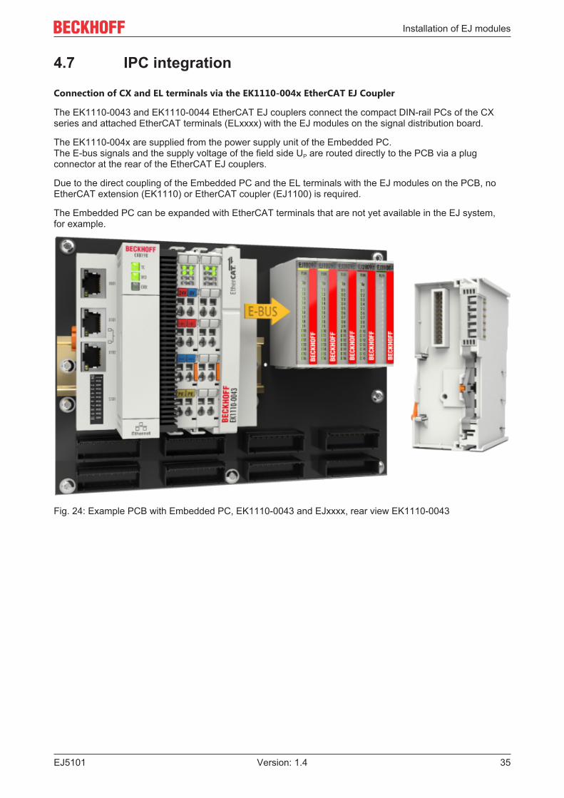
Connection of CX and EL terminals via the EK1110-004x EtherCAT EJ Coupler
The EK1110-0043 and EK1110-0044 EtherCAT EJ couplers connect the compact DIN-rail PCs of the CXseries and attached EtherCAT terminals (ELxxxx) with the EJ modules on the signal distribution board.
The EK1110-004x are supplied from the power supply unit of the Embedded PC.The E-bus signals and the supply voltage of the field side UP are routed directly to the PCB via a plugconnector at the rear of the EtherCAT EJ couplers.
Due to the direct coupling of the Embedded PC and the EL terminals with the EJ modules on the PCB, noEtherCAT extension (EK1110) or EtherCAT coupler (EJ1100) is required.
The Embedded PC can be expanded with EtherCAT terminals that are not yet available in the EJ system,for example.
Fig. 24: Example PCB with Embedded PC, EK1110-0043 and EJxxxx, rear view EK1110-0043

Installation of EJ modules
EJ510136 Version: 1.4
Connection of C6015 / C6017 via the EJ110x-00xx EtherCAT Coupler
Thanks to their ultra-compact design and versatile mounting options, the C6015 and C6017 IPCs are ideallysuited for connection to an EJ system.
In combination with the ZS5000-0003 mounting set, it is possible to place the C6015 and C6017 IPCscompactly on the signal distribution board.The EJ system is optimally connected to the IPC via the corresponding EtherCAT cable (see following Fig.[A]).The IPC can be supplied directly via the signal distribution board using the enclosed power plug (see Fig. [B]below).
NOTEPositioning on the signal distribution boardThe dimensions and distances for placement and other details can be found in the DesignGuide and the documentation for the individual components.
The figure below shows the connection of a C6015 IPC to an EJ system as an example. The componentsshown are schematic, to illustrate the functionality.
Fig. 25: Example for the connection of a C6015 IPC to an EJ system
Installation of EJ modules
EJ5101 37Version: 1.4
4.8 Disassembly of the signal distribution board WARNING
Risk of injury through electric shock and damage to the device!Bring the module system into a safe, de-energized state before starting installation, disassembly or wiringof the modules.
NOTERisk of damage to components through electrostatic discharge!Observe the regulations for ESD protection.
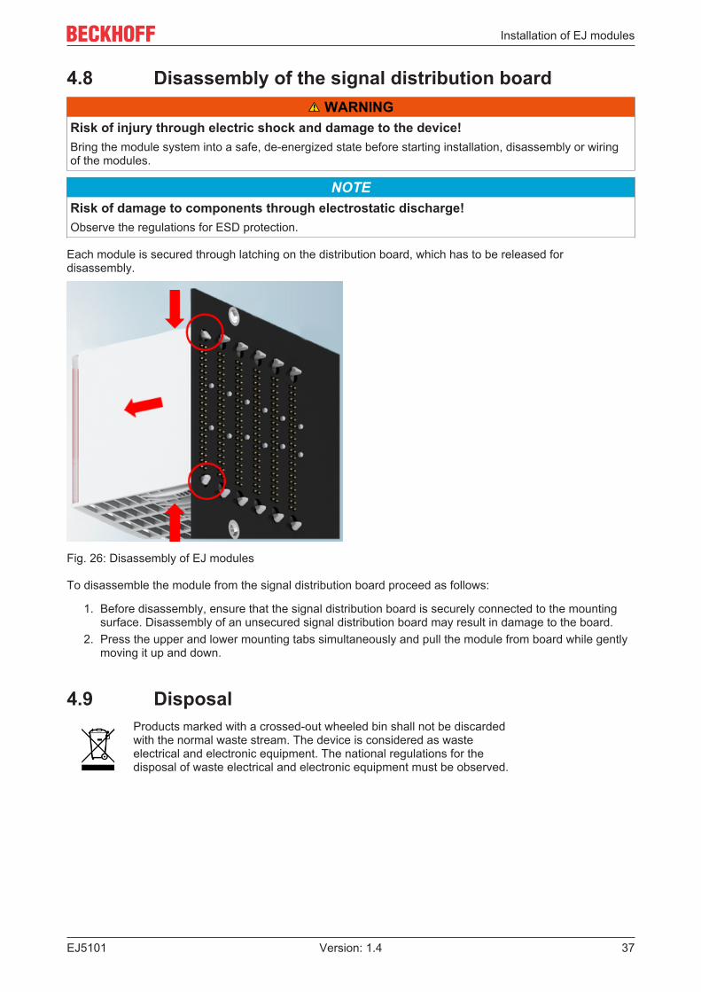
Each module is secured through latching on the distribution board, which has to be released fordisassembly.
Fig. 26: Disassembly of EJ modules
To disassemble the module from the signal distribution board proceed as follows:
1. Before disassembly, ensure that the signal distribution board is securely connected to the mountingsurface. Disassembly of an unsecured signal distribution board may result in damage to the board.
2. Press the upper and lower mounting tabs simultaneously and pull the module from board while gentlymoving it up and down.
4.9 DisposalProducts marked with a crossed-out wheeled bin shall not be discardedwith the normal waste stream. The device is considered as wasteelectrical and electronic equipment. The national regulations for thedisposal of waste electrical and electronic equipment must be observed.
EtherCAT basics
EJ510138 Version: 1.4
5 EtherCAT basicsPlease refer to the EtherCAT System Documentation for the EtherCAT fieldbus basics.
Commissioning
EJ5101 39Version: 1.4
6 Commissioning
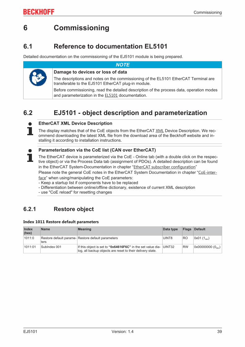
6.1 Reference to documentation EL5101Detailed documentation on the commissioning of the EJ5101 module is being prepared.
NOTEDamage to devices or loss of dataThe descriptions and notes on the commissioning of the EL5101 EtherCAT Terminal aretransferable to the EJ5101 EtherCAT plug-in module.Before commissioning, read the detailed description of the process data, operation modesand parameterization in the EL5101 documentation.
6.2 EJ5101 - object description and parameterizationEtherCAT XML Device DescriptionThe display matches that of the CoE objects from the EtherCAT XML Device Description. We rec-ommend downloading the latest XML file from the download area of the Beckhoff website and in-stalling it according to installation instructions.
Parameterization via the CoE list (CAN over EtherCAT)The EtherCAT device is parameterized via the CoE - Online tab (with a double click on the respec-tive object) or via the Process Data tab (assignment of PDOs). A detailed description can be foundin the EtherCAT System-Documentation in chapter “EtherCAT subscriber configuration”Please note the general CoE notes in the EtherCAT System Documentation in chapter “CoE-inter-face” when using/manipulating the CoE parameters:- Keep a startup list if components have to be replaced- Differentiation between online/offline dictionary, existence of current XML description- use "CoE reload" for resetting changes
6.2.1 Restore object
Index 1011 Restore default parameters
Index(hex)
Name Meaning Data type Flags Default
1011:0 Restore default parame-ters
Restore default parameters UINT8 RO 0x01 (1dec)
1011:01 SubIndex 001 If this object is set to “0x64616F6C” in the set value dia-log, all backup objects are reset to their delivery state.
UINT32 RW 0x00000000 (0dec)

Commissioning
EJ510140 Version: 1.4
6.2.2 Configuration data
6.2.2.1 0x8000, 0x8001 - simple operating mode
Index 8000 Non-Volatile Settings 0
Index(hex)
Name Meaning Data type Flags Default
8000:0 Non-Volatile Settings 0 Maximum subindex UINT8 RO 0x05 (5dec)8000:01 Enable register reload The counter counts up to the Counter reload value
(0x8001:02) or is loaded with the Counter reload value(0x8001:02) in the event of an underflow
Example 360° encoder with set bit:Moves in positive direction via Counter reload value: Re-set counter value to 0
Moves in negative direction less than 0: Reset countervalue to Counter reload value.
BOOLEAN RW 0x00 (0dec)
8000:02 Enable index reset Activates input “C” for resetting the counter.
Example 360° encoder with set bit:Moves in positive direction (signal at input “C”): Resetcounter value to 0
Moves in negative direction (signal at input “C”): under-flow with FFFF, FFFE etc.)
BOOLEAN RW 0x00 (0dec)
8000:03 Enable FWD count FALSE The module operates in quadrature decoder mode.
TRUE The module operates as a counter, counting direction to-wards input B.
BOOLEAN RW 0x00 (0dec)
8000:04 Enable pos. gate Gate input responds to positive edge and locks thecounter
BOOLEAN RW 0x01 (1dec)
8000:05 Enable neg. gate Gate input responds to negative edge and locks thecounter
BOOLEAN RW 0x00 (0dec)
Index 8001 Non-Volatile Settings 1
Index(hex)
Name Meaning Data type Flags Default
8001:0 Non-Volatile Settings 1 Maximum subindex UINT8 RO 0x02 (2dec)8001:01 Frequency window The value specifies the size of the time window for the
variable Window (0x6000:06).Resolution: 16 µs; e.g. default value: 16 µs x 100dec = 1.6 ms
UINT16 RW 0x0064 (100dec)
8001:02 Counter reload value If Enable register reload (0x8000:01) is TRUE, thecounter counts up to this value or is loaded with thisvalue in the event of an underflow
UINT16 RW 0xFFFF (65535dec)
Commissioning
EJ5101 41Version: 1.4
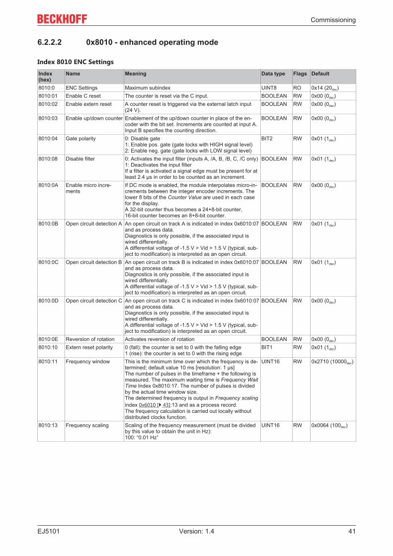
6.2.2.2 0x8010 - enhanced operating mode
Index 8010 ENC Settings
Index(hex)
Name Meaning Data type Flags Default
8010:0 ENC Settings Maximum subindex UINT8 RO 0x14 (20dec)8010:01 Enable C reset The counter is reset via the C input. BOOLEAN RW 0x00 (0dec)8010:02 Enable extern reset A counter reset is triggered via the external latch input
(24 V).BOOLEAN RW 0x00 (0dec)
8010:03 Enable up/down counter Enablement of the up/down counter in place of the en-coder with the bit set. Increments are counted at input A. Input B specifies the counting direction.
BOOLEAN RW 0x00 (0dec)
8010:04 Gate polarity 0: Disable gate1: Enable pos. gate (gate locks with HIGH signal level)2: Enable neg. gate (gate locks with LOW signal level)
BIT2 RW 0x01 (1dec)
8010:08 Disable filter 0: Activates the input filter (inputs A, /A, B, /B, C, /C only)1: Deactivates the input filterIf a filter is activated a signal edge must be present for atleast 2.4 µs in order to be counted as an increment.
BOOLEAN RW 0x01 (1dec)
8010:0A Enable micro incre-ments
If DC mode is enabled, the module interpolates micro-in-crements between the integer encoder increments. Thelower 8 bits of the Counter Value are used in each casefor the display.A 32-bit counter thus becomes a 24+8-bit counter, 16-bit counter becomes an 8+8-bit counter.
BOOLEAN RW 0x00 (0dec)
8010:0B Open circuit detection A An open circuit on track A is indicated in index 0x6010:07and as process data.Diagnostics is only possible, if the associated input iswired differentially.A differential voltage of -1.5 V > Vid > 1.5 V (typical, sub-ject to modification) is interpreted as an open circuit.
BOOLEAN RW 0x01 (1dec)
8010:0C Open circuit detection B An open circuit on track B is indicated in index 0x6010:07and as process data.Diagnostics is only possible, if the associated input iswired differentially.A differential voltage of -1.5 V > Vid > 1.5 V (typical, sub-ject to modification) is interpreted as an open circuit.
BOOLEAN RW 0x01 (1dec)
8010:0D Open circuit detection C An open circuit on track C is indicated in index 0x6010:07and as process data.Diagnostics is only possible, if the associated input iswired differentially.A differential voltage of -1.5 V > Vid > 1.5 V (typical, sub-ject to modification) is interpreted as an open circuit.
BOOLEAN RW 0x00 (0dec)
8010:0E Reversion of rotation Activates reversion of rotation BOOLEAN RW 0x00 (0dec)8010:10 Extern reset polarity 0 (fall): the counter is set to 0 with the falling edge
1 (rise): the counter is set to 0 with the rising edgeBIT1 RW 0x01 (1dec)
8010:11 Frequency window This is the minimum time over which the frequency is de-termined; default value 10 ms [resolution: 1 µs]The number of pulses in the timeframe + the following ismeasured. The maximum waiting time is Frequency WaitTime Index 0x8010:17. The number of pulses is dividedby the actual time window size.The determined frequency is output in Frequency scalingindex 0x6010 [} 43]:13 and as a process record.The frequency calculation is carried out locally withoutdistributed clocks function.
UINT16 RW 0x2710 (10000dec)
8010:13 Frequency scaling Scaling of the frequency measurement (must be dividedby this value to obtain the unit in Hz):100: “0.01 Hz”
UINT16 RW 0x0064 (100dec)
Commissioning
EJ510142 Version: 1.4
Index(hex)
Name Meaning Data type Flags Default
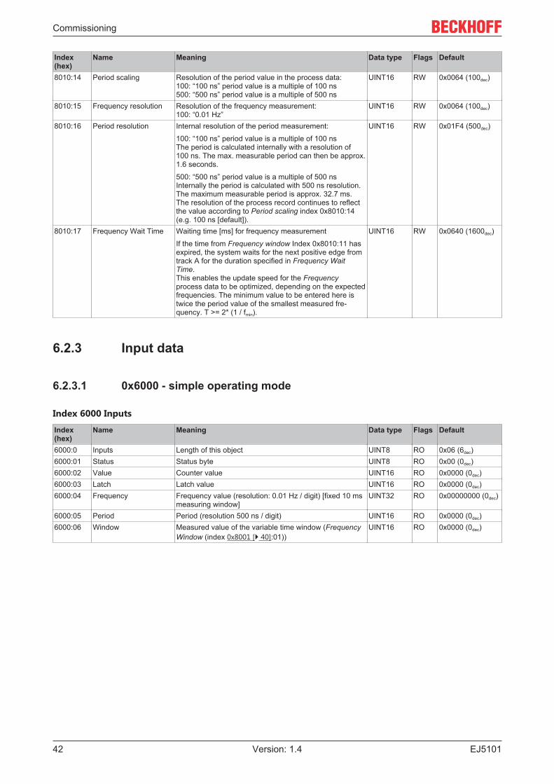
8010:14 Period scaling Resolution of the period value in the process data:100: “100 ns” period value is a multiple of 100 ns 500: “500 ns” period value is a multiple of 500 ns
UINT16 RW 0x0064 (100dec)
8010:15 Frequency resolution Resolution of the frequency measurement:100: “0.01 Hz”
UINT16 RW 0x0064 (100dec)
8010:16 Period resolution Internal resolution of the period measurement:
100: “100 ns” period value is a multiple of 100 nsThe period is calculated internally with a resolution of100 ns. The max. measurable period can then be approx.1.6 seconds.
500: “500 ns” period value is a multiple of 500 nsInternally the period is calculated with 500 ns resolution.The maximum measurable period is approx. 32.7 ms.The resolution of the process record continues to reflectthe value according to Period scaling index 0x8010:14(e.g. 100 ns [default]).
UINT16 RW 0x01F4 (500dec)
8010:17 Frequency Wait Time Waiting time [ms] for frequency measurement
If the time from Frequency window Index 0x8010:11 hasexpired, the system waits for the next positive edge fromtrack A for the duration specified in Frequency WaitTime.This enables the update speed for the Frequencyprocess data to be optimized, depending on the expectedfrequencies. The minimum value to be entered here istwice the period value of the smallest measured fre-quency. T >= 2* (1 / fmin).
UINT16 RW 0x0640 (1600dec)
6.2.3 Input data
6.2.3.1 0x6000 - simple operating mode
Index 6000 Inputs
Index(hex)
Name Meaning Data type Flags Default
6000:0 Inputs Length of this object UINT8 RO 0x06 (6dec)6000:01 Status Status byte UINT8 RO 0x00 (0dec)6000:02 Value Counter value UINT16 RO 0x0000 (0dec)6000:03 Latch Latch value UINT16 RO 0x0000 (0dec)6000:04 Frequency Frequency value (resolution: 0.01 Hz / digit) [fixed 10 ms
measuring window]UINT32 RO 0x00000000 (0dec)
6000:05 Period Period (resolution 500 ns / digit) UINT16 RO 0x0000 (0dec)6000:06 Window Measured value of the variable time window (Frequency
Window (index 0x8001 [} 40]:01))UINT16 RO 0x0000 (0dec)

Commissioning
EJ5101 43Version: 1.4
6.2.3.2 0x6010 - enhanced operating mode
Index 6010 ENC Inputs
Index(hex)
Name Meaning Data type Flags Default
6010:0 ENC Inputs Maximum subindex UINT8 RO 0x16 (22dec)6010:01 Latch C valid The counter value was latched with the “C” input.
The data in Latch value index 0x6010:12 correspond tothe latched value with the bit set. To re-enable the latchinput, Enable latch C index 0x7010 [} 44]:01 must becanceled and then reset.
BOOLEAN RO 0x00 (0dec)
6010:02 Latch extern valid The counter value was locked via the external latch.
The data in Latch value index 0x6010:12 correspond tothe latched value with the bit set. To re-enable the latchinput, Enable latch extern on positive edge index0x7010:02 or Enable latch extern on negative edge index0x7010:04 must first be canceled and then reset.
BOOLEAN RO 0x00 (0dec)
6010:03 Set counter done The counter was set. BOOLEAN RO 0x00 (0dec)6010:04 Counter underflow The counter has passed the zero crossing backwards.
Overflow/underflow control is inactive in combination witha reset function (C/external).
BOOLEAN RO 0x00 (0dec)
6010:05 Counter overflow Counter overflow.
Overflow/underflow control is inactive in combination witha reset function (C/external).
BOOLEAN RO 0x00 (0dec)
6010:06 Status of input status State of the status input (alarm Input 1) BOOLEAN RO 0x00 (0dec)6010:07 Open circuit Indicates an open circuit.
Configuration via index 0x8010: [} 41]0B, 0x8010:0C,0x8010:0D
BOOLEAN RO 0x00 (0dec)
6010:08 Extrapolation stall The extrapolated part of the counter is invalid BOOLEAN RO 0x00 (0dec)6010:09 Status of input A Status of input A BOOLEAN RO 0x00 (0dec)6010:0A Status of input B Status of input B BOOLEAN RO 0x00 (0dec)6010:0B Status of input C Status of input C BOOLEAN RO 0x00 (0dec)6010:0C Status of input gate The state of the gate input BOOLEAN RO 0x00 (0dec)6010:0D Status of extern latch Status of the extern latch input BOOLEAN RO 0x00 (0dec)6010:0E Sync Error The Sync Error bit is only required for the DC mode. It in-
dicates whether a synchronization error occurred in theexpired cycle.This means a SYNC signal was triggered in the module,although no new process data were available (0=ok,1=nok).
BOOLEAN RO 0x00 (0dec)
6010:0F TxPDO State Validity of the data of the associated TxPDO (0 = valid, 1= invalid).
BOOLEAN RO 0x00 (0dec)
6010:10 TxPDO Toggle The TxPDO toggle is toggled by the slave when the dataof the associated TxPDO is updated.
BOOLEAN RO 0x00 (0dec)
6010:11 Counter value Counter value UINT32 RO 0x00000000 (0dec)6010:12 Latch value Latch value UINT32 RO 0x00000000 (0dec)6010:13 Frequency value The frequency (setting of the scaling in index 0x8010:13
and resolution in index 0x8010:15)UINT32 RO 0x00000000 (0dec)
6010:14 Period value The period (setting of the scaling in index 0x8010:14 andthe resolution in index 0x8010:16)
UINT32 RO 0x00000000 (0dec)
6010:16 Timestamp Timestamp of the last counter change UINT64 RO

Commissioning
EJ510144 Version: 1.4
6.2.4 Output data
6.2.4.1 0x7000 - simple operating mode
Index 7000 Outputs
Index(hex)
Name Meaning Data type Flags Default
7000:0 Outputs Length of this object UINT8 RO 0x02 (2dec)7000:01 Ctrl Control byte UINT8 RO 0x00 (0dec)7000:02 Value The counter value to be set via “CNT_SET” (CB.02). UINT16 RO 0x0000 (0dec)
6.2.4.2 0x7010 - enhanced operating mode
Index 7010 ENC Outputs
Index(hex)
Name Meaning Data type Flags Default
7010:0 ENC Outputs Maximum subindex UINT8 RO 0x11 (17dec)7010:01 Enable latch C Activate latching via input “C”. BOOLEAN RO 0x00 (0dec)7010:02 Enable latch extern on
positive edgeActivate external latch with positive edge. BOOLEAN RO 0x00 (0dec)
7010:03 Set counter Set counter value BOOLEAN RO 0x00 (0dec)7010:04 Enable latch extern on
negative edgeActivate external latch with negative edge. BOOLEAN RO 0x00 (0dec)
7010:11 Set counter value The counter value to be set via Set counter (index0x7010:03).
UINT32 RO 0x00000000 (0dec)
6.2.5 Information and diagnostic data / channel-specific
Index A010 ENC diag data (only for enhanced operating mode)
Index(hex)
Name Meaning Data type Flags Default
A010:0 ENC diag data Maximum subindex UINT8 RO 0x03 (3dec)A010:01 Open circuit A Open circuit on track A BOOLEAN RO 0x00 (0dec)A010:02 Open circuit B Open circuit on track B BOOLEAN RO 0x00 (0dec)A010:03 Open circuit C Open circuit on track C BOOLEAN RO 0x00 (0dec)
6.2.6 Standard objectsThe standard objects have the same meaning for all EtherCAT slaves.
Index 1000 Device type
Index (hex) Name Meaning Data type Flags Default1000:0 Device type Device type of the EtherCAT slave: the Lo-Word con-
tains the CoE profile used (5001). The Hi-Word con-tains the module profile according to the modular de-vice profile.
UINT32 RO 0x00001389(5001dec)
Index 1008 Device name
Index(hex)
Name Meaning Data type Flags Default
1008:0 Device name Device name of the EtherCAT slave STRING RO EJ5101

Commissioning
EJ5101 45Version: 1.4
Index 1009 Hardware version
Index(hex)
Name Meaning Data type Flags Default
1009:0 Hardware version Hardware version of the EtherCAT slave STRING RO 09
Index 100A Software version
Index(hex)
Name Meaning Data type Flags Default
100A:0 Software version Firmware version of the EtherCAT slave STRING RO 10
Index 1018 Identity
Index(hex)
Name Meaning Data type Flags Default
1018:0 Identity Information for identifying the slave UINT8 RO 0x04 (4dec)1018:01 Vendor ID Vendor ID of the EtherCAT slave UINT32 RO 0x00000002 (2dec)1018:02 Product code Product code of the EtherCAT slave UINT32 RO 0x13ED2852
(334309458dec)1018:03 Revision Revision number of the EtherCAT slave; the Low Word
(bit 0-15) indicates the special terminal number, the HighWord (bit 16-31) refers to the device description
UINT32 RO 0x00000000(00000000dec)
1018:04 Serial number Serial number of the EtherCAT slave; the Low Byte (bit0-7) of the Low Word contains the year of production, theHigh Byte (bit 8-15) of the Low Word contains the weekof production, the High Word (bit 16-31) is 0
UINT32 RO 0x00000000 (0dec)
Index 10F0 Backup parameter handling
Index(hex)
Name Meaning Data type Flags Default
10F0:0 Backup parameter han-dling
Information for standardized loading and saving ofbackup entries
UINT8 RO 0x01 (1dec)
10F0:01 Checksum Checksum across all backup entries of the EtherCATslave
UINT32 RO 0x00000000 (0dec)
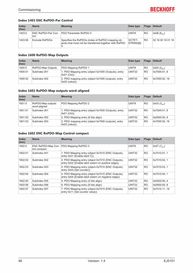
Index 1400 RxPDO-Par outputs
Index(hex)
Name Meaning Data type Flags Default
1400:0 RxPDO-Par outputs PDO Parameter RxPDO 1 UINT8 RO 0x06 (6dec)1400:06 Exclude RxPDOs Specifies the RxPDOs (index of RxPDO mapping ob-
jects) that must not be transferred together with RxPDO1
OCTET-STRING[6]
RO 01 16 02 16 03 16
Index 1401 RxPDO-Par outputs word-aligned
Index(hex)
Name Meaning Data type Flags Default
1401:0 RxPDO-Par outputsword-aligned
PDO Parameter RxPDO 2 UINT8 RO 0x06 (6dec)
1401:06 Exclude RxPDOs Specifies the RxPDOs (index of RxPDO mapping ob-jects) that must not be transferred together with RxPDO2
OCTET-STRING[6]
RO 00 16 02 16 03 16
Index 1402 ENC RxPDO-Par Control compact
Index(hex)
Name Meaning Data type Flags Default
1402:0 ENC RxPDO-Par Con-trol compact
PDO Parameter RxPDO 3 UINT8 RO 0x06 (6dec)
1402:06 Exclude RxPDOs Specifies the RxPDOs (index of RxPDO mapping ob-jects) that must not be transferred together with RxPDO3
OCTET-STRING[6]
RO 03 16 00 16 01 16
Commissioning
EJ510146 Version: 1.4
Index 1403 ENC RxPDO-Par Control
Index(hex)
Name Meaning Data type Flags Default
1403:0 ENC RxPDO-Par Con-trol
PDO Parameter RxPDO 4 UINT8 RO 0x06 (6dec)
1403:06 Exclude RxPDOs Specifies the RxPDOs (index of RxPDO mapping ob-jects) that must not be transferred together with RxPDO4
OCTET-STRING[6]
RO 02 16 00 16 01 16
Index 1600 RxPDO-Map Outputs
Index(hex)
Name Meaning Data type Flags Default
1600:0 RxPDO-Map Outputs PDO Mapping RxPDO 1 UINT8 RO 0x02 (2dec)1600:01 SubIndex 001 1. PDO Mapping entry (object 0x7000 (Outputs), entry
0x01 (Ctrl))UINT32 RO 0x7000:01, 8
1600:02 SubIndex 002 2. PDO mapping entry (object 0x7000 (outputs), entry0x02 (value))
UINT32 RO 0x7000:02, 16
Index 1601 RxPDO-Map outputs word-aligned
Index(hex)
Name Meaning Data type Flags Default
1601:0 RxPDO-Map outputsword-aligned
PDO Mapping RxPDO 2 UINT8 RO 0x03 (3dec)
1601:01 SubIndex 001 1. PDO Mapping entry (object 0x7000 (Outputs), entry0x01 (Ctrl))
UINT32 RO 0x7000:01, 8
1601:02 SubIndex 002 2. PDO Mapping entry (8 bits align) UINT32 RO 0x0000:00, 81601:03 SubIndex 003 3. PDO mapping entry (object 0x7000 (outputs), entry
0x02 (value))UINT32 RO 0x7000:02, 16
Index 1602 ENC RxPDO-Map Control compact
Index(hex)
Name Meaning Data type Flags Default
1602:0 ENC RxPDO-Map Con-trol compact
PDO Mapping RxPDO 3 UINT8 RO 0x07 (7dec)
1602:01 SubIndex 001 1. PDO Mapping entry (object 0x7010 (ENC Outputs),entry 0x01 (Enable latch C))
UINT32 RO 0x7010:01, 1
1602:02 SubIndex 002 2. PDO Mapping entry (object 0x7010 (ENC Outputs),entry 0x02 (Enable latch extern on positive edge))
UINT32 RO 0x7010:02, 1
1602:03 SubIndex 003 3. PDO Mapping entry (object 0x7010 (ENC Outputs),entry 0x03 (Set counter))
UINT32 RO 0x7010:03, 1
1602:04 SubIndex 004 4. PDO Mapping entry (object 0x7010 (ENC Outputs),entry 0x04 (Enable latch extern on negative edge))
UINT32 RO 0x7010:04, 1
1602:05 SubIndex 005 5. PDO Mapping entry (4 bits align) UINT32 RO 0x0000:00, 41602:06 SubIndex 006 6. PDO Mapping entry (8 bits align) UINT32 RO 0x0000:00, 81602:07 SubIndex 007 7. PDO Mapping entry (object 0x7010 (ENC Outputs),
entry 0x11 (Set counter value))UINT32 RO 0x7010:11, 16

Commissioning
EJ5101 47Version: 1.4
Index 1603 ENC RxPDO-Map Control
Index(hex)
Name Meaning Data type Flags Default
1603:0 ENC RxPDO-Map Con-trol
PDO Mapping RxPDO 4 UINT8 RO 0x07 (7dec)
1603:01 SubIndex 001 1. PDO Mapping entry (object 0x7010 (ENC Outputs),entry 0x01 (Enable latch C))
UINT32 RO 0x7010:01, 1
1603:02 SubIndex 002 2. PDO Mapping entry (object 0x7010 (ENC Outputs),entry 0x02 (Enable latch extern on positive edge))
UINT32 RO 0x7010:02, 1
1603:03 SubIndex 003 3. PDO Mapping entry (object 0x7010 (ENC Outputs),entry 0x03 (Set counter))
UINT32 RO 0x7010:03, 1
1603:04 SubIndex 004 4. PDO Mapping entry (object 0x7010 (ENC Outputs),entry 0x04 (Enable latch extern on negative edge))
UINT32 RO 0x7010:04, 1
1603:05 SubIndex 005 5. PDO Mapping entry (4 bits align) UINT32 RO 0x0000:00, 41603:06 SubIndex 006 6. PDO Mapping entry (8 bits align) UINT32 RO 0x0000:00, 81603:07 SubIndex 007 7. PDO Mapping entry (object 0x7010 (ENC Outputs),
entry 0x11 (Set counter value))UINT32 RO 0x7010:11, 32
Index 1800 TxPDO-Par inputs
Index(hex)
Name Meaning Data type Flags Default
1800:0 TxPDO-Par inputs PDO parameter TxPDO 1 UINT8 RO 0x06 (6dec)1800:06 Exclude TxPDOs Specifies the TxPDOs (index of TxPDO mapping objects)
that must not be transferred together with TxPDO 1OCTET-STRING[14]
RO 01 1A 03 1A 041A 05 1A 06 1A07 1A 08 1A
Index 1801 TxPDO-Par inputs word-aligned
Index(hex)
Name Meaning Data type Flags Default
1801:0 TxPDO-Par inputsword-aligned
PDO parameter TxPDO 2 UINT8 RO 0x06 (6dec)
1801:06 Exclude TxPDOs Specifies the TxPDOs (index of TxPDO mapping objects)that must not be transferred together with TxPDO 2
OCTET-STRING[14]
RO 00 1A 03 1A 041A 05 1A 06 1A07 1A 08 1A
Index 1802 TxPDO-Par Inputs optional
Index(hex)
Name Meaning Data type Flags Default
1802:0 TxPDO-Par Inputs op-tional
PDO parameter TxPDO 3 UINT8 RO 0x06 (6dec)
1802:06 Exclude TxPDOs Specifies the TxPDOs (index of TxPDO mapping objects)that must not be transferred together with TxPDO 3
OCTET-STRING[14]
RO 03 1A 04 1A 051A 06 1A 07 1A08 1A 00 00
Index 1803 ENC TxPDO-Par Status compact
Index(hex)
Name Meaning Data type Flags Default
1803:0 ENC TxPDO-Par Statuscompact
PDO parameter TxPDO 4 UINT8 RO 0x06 (6dec)
1803:06 Exclude TxPDOs Specifies the TxPDOs (index of TxPDO mapping objects)that must not be transferred together with TxPDO 4
OCTET-STRING[14]
RO 04 1A 00 1A 011A 02 1A 00 0000 00 00 00
Index 1804 ENC TxPDO-Par Status
Index(hex)
Name Meaning Data type Flags Default
1804:0 ENC TxPDO-Par Status PDO parameter TxPDO 5 UINT8 RO 0x06 (6dec)1804:06 Exclude TxPDOs Specifies the TxPDOs (index of TxPDO mapping objects)
that must not be transferred together with TxPDO 5OCTET-STRING[14]
RO 03 1A 00 1A 011A 02 1A 00 0000 00 00 00
Commissioning
EJ510148 Version: 1.4
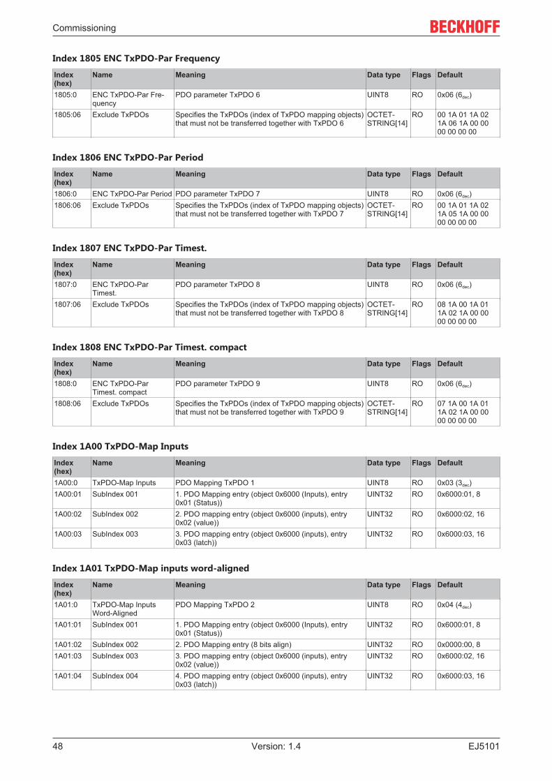
Index 1805 ENC TxPDO-Par Frequency
Index(hex)
Name Meaning Data type Flags Default
1805:0 ENC TxPDO-Par Fre-quency
PDO parameter TxPDO 6 UINT8 RO 0x06 (6dec)
1805:06 Exclude TxPDOs Specifies the TxPDOs (index of TxPDO mapping objects)that must not be transferred together with TxPDO 6
OCTET-STRING[14]
RO 00 1A 01 1A 021A 06 1A 00 0000 00 00 00
Index 1806 ENC TxPDO-Par Period
Index(hex)
Name Meaning Data type Flags Default
1806:0 ENC TxPDO-Par Period PDO parameter TxPDO 7 UINT8 RO 0x06 (6dec)1806:06 Exclude TxPDOs Specifies the TxPDOs (index of TxPDO mapping objects)
that must not be transferred together with TxPDO 7OCTET-STRING[14]
RO 00 1A 01 1A 021A 05 1A 00 0000 00 00 00
Index 1807 ENC TxPDO-Par Timest.
Index(hex)
Name Meaning Data type Flags Default
1807:0 ENC TxPDO-ParTimest.
PDO parameter TxPDO 8 UINT8 RO 0x06 (6dec)
1807:06 Exclude TxPDOs Specifies the TxPDOs (index of TxPDO mapping objects)that must not be transferred together with TxPDO 8
OCTET-STRING[14]
RO 08 1A 00 1A 011A 02 1A 00 0000 00 00 00
Index 1808 ENC TxPDO-Par Timest. compact
Index(hex)
Name Meaning Data type Flags Default
1808:0 ENC TxPDO-ParTimest. compact
PDO parameter TxPDO 9 UINT8 RO 0x06 (6dec)
1808:06 Exclude TxPDOs Specifies the TxPDOs (index of TxPDO mapping objects)that must not be transferred together with TxPDO 9
OCTET-STRING[14]
RO 07 1A 00 1A 011A 02 1A 00 0000 00 00 00
Index 1A00 TxPDO-Map Inputs
Index(hex)
Name Meaning Data type Flags Default
1A00:0 TxPDO-Map Inputs PDO Mapping TxPDO 1 UINT8 RO 0x03 (3dec)1A00:01 SubIndex 001 1. PDO Mapping entry (object 0x6000 (Inputs), entry
0x01 (Status))UINT32 RO 0x6000:01, 8
1A00:02 SubIndex 002 2. PDO mapping entry (object 0x6000 (inputs), entry0x02 (value))
UINT32 RO 0x6000:02, 16
1A00:03 SubIndex 003 3. PDO mapping entry (object 0x6000 (inputs), entry0x03 (latch))
UINT32 RO 0x6000:03, 16
Index 1A01 TxPDO-Map inputs word-aligned
Index(hex)
Name Meaning Data type Flags Default
1A01:0 TxPDO-Map InputsWord-Aligned
PDO Mapping TxPDO 2 UINT8 RO 0x04 (4dec)
1A01:01 SubIndex 001 1. PDO Mapping entry (object 0x6000 (Inputs), entry0x01 (Status))
UINT32 RO 0x6000:01, 8
1A01:02 SubIndex 002 2. PDO Mapping entry (8 bits align) UINT32 RO 0x0000:00, 81A01:03 SubIndex 003 3. PDO mapping entry (object 0x6000 (inputs), entry
0x02 (value))UINT32 RO 0x6000:02, 16
1A01:04 SubIndex 004 4. PDO mapping entry (object 0x6000 (inputs), entry0x03 (latch))
UINT32 RO 0x6000:03, 16

Commissioning
EJ5101 49Version: 1.4
Index 1A02 TxPDO-Map Inputs optional
Index(hex)
Name Meaning Data type Flags Default
1A02:0 TxPDO-Map Inputs op-tional
PDO Mapping TxPDO 3 UINT8 RO 0x03 (3dec)
1A02:01 SubIndex 001 1. PDO Mapping entry (object 0x6000 (Inputs), entry0x04 (Frequency))
UINT32 RO 0x6000:04, 32
1A02:02 SubIndex 002 2. PDO Mapping entry (object 0x6000 (Inputs), entry0x05 (Period))
UINT32 RO 0x6000:05, 16
1A02:03 SubIndex 003 3. PDO Mapping entry (object 0x6000 (Inputs), entry0x06 (Window))
UINT32 RO 0x6000:06, 16
Index 1A03 ENC TxPDO-Map Status compact
Index(hex)
Name Meaning Data type Flags Default
1A03:0 ENC TxPDO-Map Sta-tus compact
PDO Mapping TxPDO 4 UINT8 RO 0x12 (18dec)
1A03:01 SubIndex 001 1. PDO Mapping entry (object 0x6010 (ENC Inputs), en-try 0x01 (Latch C valid))
UINT32 RO 0x6010:01, 1
1A03:02 SubIndex 002 2. PDO Mapping entry (object 0x6010 (ENC Inputs), en-try 0x02 (Latch extern valid))
UINT32 RO 0x6010:02, 1
1A03:03 SubIndex 003 3. PDO Mapping entry (object 0x6010 (ENC Inputs), en-try 0x03 (Set counter done))
UINT32 RO 0x6010:03, 1
1A03:04 SubIndex 004 4. PDO Mapping entry (object 0x6010 (ENC Inputs), en-try 0x04 (Counter underflow))
UINT32 RO 0x6010:04, 1
1A03:05 SubIndex 005 5. PDO Mapping entry (object 0x6010 (ENC Inputs), en-try 0x05 (Counter overflow))
UINT32 RO 0x6010:05, 1
1A03:06 SubIndex 006 6. PDO Mapping entry (object 0x6010 (ENC Inputs), en-try 0x06 (input status))
UINT32 RO 0x6010:06, 1
1A03:07 SubIndex 007 7. PDO Mapping entry (object 0x6010 (ENC Inputs), en-try 0x07 (Open circuit))
UINT32 RO 0x6010:07, 1
1A03:08 SubIndex 008 8. PDO Mapping entry (object 0x6010 (ENC Inputs), en-try 0x08 (Extrapolation stall))
UINT32 RO 0x6010:08, 1
1A03:09 SubIndex 009 9. PDO Mapping entry (object 0x6010 (ENC Inputs), en-try 0x09 (Status of input A))
UINT32 RO 0x6010:09, 1
1A03:0A SubIndex 010 10. PDO Mapping entry (object 0x6010 (ENC Inputs), en-try 0x0A (Status of input B))
UINT32 RO 0x6010:0A, 1
1A03:0B SubIndex 011 11. PDO Mapping entry (object 0x6010 (ENC Inputs), en-try 0x0B (Status of input C))
UINT32 RO 0x6010:0B, 1
1A03:0C SubIndex 012 12. PDO Mapping entry (object 0x6010 (ENC Inputs), en-try 0x0C (Status of input gate))
UINT32 RO 0x6010:0C, 1
1A03:0D SubIndex 013 13. PDO Mapping entry (object 0x6010 (ENC Inputs), en-try 0x0D (Status of extern latch))
UINT32 RO 0x6010:0D, 1
1A03:0E SubIndex 014 14. PDO Mapping entry (object 0x6010 (ENC Inputs), en-try 0x0E (Sync error))
UINT32 RO 0x6010:0E, 1
1A03:0F SubIndex 015 15. PDO Mapping entry (object 0x6010 (ENC Inputs), en-try 0x0F (TxPDO State))
UINT32 RO 0x6010:0F, 1
1A03:10 SubIndex 016 16. PDO Mapping entry (object 0x6010 (ENC Inputs), en-try 0x10 (TxPDO Toggle))
UINT32 RO 0x6010:10, 1
1A03:11 SubIndex 017 17. PDO Mapping entry (object 0x6010 (ENC Inputs), en-try 0x11 (Counter value))
UINT32 RO 0x6010:11, 16
1A03:12 SubIndex 018 18. PDO Mapping entry (object 0x6010 (ENC Inputs), en-try 0x12 (Latch value))
UINT32 RO 0x6010:12, 16

Commissioning
EJ510150 Version: 1.4
Index 1A04 ENC TxPDO-Map Status
Index(hex)
Name Meaning Data type Flags Default
1A04:0 ENC TxPDO-Map Sta-tus
PDO Mapping TxPDO 5 UINT8 RO 0x12 (18dec)
1A04:01 SubIndex 001 1. PDO Mapping entry (object 0x6010 (ENC Inputs), en-try 0x01 (Latch C valid))
UINT32 RO 0x6010:01, 1
1A04:02 SubIndex 002 2. PDO Mapping entry (object 0x6010 (ENC Inputs), en-try 0x02 (Latch extern valid))
UINT32 RO 0x6010:02, 1
1A04:03 SubIndex 003 3. PDO Mapping entry (object 0x6010 (ENC Inputs), en-try 0x03 (Set counter done))
UINT32 RO 0x6010:03, 1
1A04:04 SubIndex 004 4. PDO Mapping entry (object 0x6010 (ENC Inputs), en-try 0x04 (Counter underflow))
UINT32 RO 0x6010:04, 1
1A04:05 SubIndex 005 5. PDO Mapping entry (object 0x6010 (ENC Inputs), en-try 0x05 (Counter overflow))
UINT32 RO 0x6010:05, 1
1A04:06 SubIndex 006 6. PDO Mapping entry (object 0x6010 (ENC Inputs), en-try 0x06 (input status))
UINT32 RO 0x6010:06, 1
1A04:07 SubIndex 007 7. PDO Mapping entry (object 0x6010 (ENC Inputs), en-try 0x07 (Open circuit))
UINT32 RO 0x6010:07, 1
1A04:08 SubIndex 008 8. PDO Mapping entry (object 0x6010 (ENC Inputs), en-try 0x08 (Extrapolation stall))
UINT32 RO 0x6010:08, 1
1A04:09 SubIndex 009 9. PDO Mapping entry (object 0x6010 (ENC Inputs), en-try 0x09 (Status of input A))
UINT32 RO 0x6010:09, 1
1A04:0A SubIndex 010 10. PDO Mapping entry (object 0x6010 (ENC Inputs), en-try 0x0A (Status of input B))
UINT32 RO 0x6010:0A, 1
1A04:0B SubIndex 011 11. PDO Mapping entry (object 0x6010 (ENC Inputs), en-try 0x0B (Status of input C))
UINT32 RO 0x6010:0B, 1
1A04:0C SubIndex 012 12. PDO Mapping entry (object 0x6010 (ENC Inputs), en-try 0x0C (Status of input gate))
UINT32 RO 0x6010:0C, 1
1A04:0D SubIndex 013 13. PDO Mapping entry (object 0x6010 (ENC Inputs), en-try 0x0D (Status of extern latch))
UINT32 RO 0x6010:0D, 1
1A04:0E SubIndex 014 14. PDO Mapping entry (object 0x6010 (ENC Inputs), en-try 0x0E (Sync error))
UINT32 RO 0x6010:0E, 1
1A04:0F SubIndex 015 15. PDO Mapping entry (object 0x6010 (ENC Inputs), en-try 0x0F (TxPDO State))
UINT32 RO 0x6010:0F, 1
1A04:10 SubIndex 016 16. PDO Mapping entry (object 0x6010 (ENC Inputs), en-try 0x10 (TxPDO Toggle))
UINT32 RO 0x6010:10, 1
1A04:11 SubIndex 017 17. PDO Mapping entry (object 0x6010 (ENC Inputs), en-try 0x11 (Counter value))
UINT32 RO 0x6010:11, 32
1A04:12 SubIndex 018 18. PDO Mapping entry (object 0x6010 (ENC Inputs), en-try 0x12 (Latch value))
UINT32 RO 0x6010:12, 32
Index 1A05 ENC TxPDO-Map Frequency
Index(hex)
Name Meaning Data type Flags Default
1A05:0 ENC TxPDO-Map Fre-quency
PDO Mapping TxPDO 6 UINT8 RO 0x01 (1dec)
1A05:01 SubIndex 001 1. PDO Mapping entry (object 0x6010 (ENC Inputs), en-try 0x13 (Frequency value))
UINT32 RO 0x6010:13, 32
Index 1A06 ENC TxPDO-Map Period
Index(hex)
Name Meaning Data type Flags Default
1A06:0 ENC TxPDO-Map Pe-riod
PDO Mapping TxPDO 7 UINT8 RO 0x01 (1dec)
1A06:01 SubIndex 001 1. PDO Mapping entry (object 0x6010 (ENC Inputs), en-try 0x14 (Period value))
UINT32 RO 0x6010:14, 32

Commissioning
EJ5101 51Version: 1.4
Index 1A07 ENC TxPDO-Map Timest.
Index(hex)
Name Meaning Data type Flags Default
1A07:0 ENC TxPDO-MapTimest.
PDO Mapping TxPDO 8 UINT8 RO 0x01 (1dec)
1A07:01 SubIndex 001 1. PDO Mapping entry (object 0x6010 (ENC Inputs), en-try 0x16 (Timestamp))
UINT32 RO 0x6010:16, 64
Index 1A08 ENC TxPDO-Map Timest. compact
Index(hex)
Name Meaning Data type Flags Default
1A08:0 ENC TxPDO-MapTimest. compact
PDO Mapping TxPDO 9 UINT8 RO 0x01 (1dec)
1A08:01 SubIndex 001 1. PDO Mapping entry (object 0x6010 (ENC Inputs), en-try 0x16 (Timestamp))
UINT32 RO 0x6010:16, 32
Index 1C00 Sync manager type
Index(hex)
Name Meaning Data type Flags Default
1C00:0 Sync manager type Using the sync managers UINT8 RO 0x04 (4dec)1C00:01 SubIndex 001 Sync-Manager Type Channel 1: Mailbox Write UINT8 RO 0x01 (1dec)1C00:02 SubIndex 002 Sync-Manager Type Channel 2: Mailbox Read UINT8 RO 0x02 (2dec)1C00:03 SubIndex 003 Sync-Manager Type Channel 3: Process Data Write
(Outputs)UINT8 RO 0x03 (3dec)
1C00:04 SubIndex 004 Sync-Manager Type Channel 4: Process Data Read (In-puts)
UINT8 RO 0x04 (4dec)
Index 1C12 RxPDO assign
Index(hex)
Name Meaning Data type Flags Default
1C12:0 RxPDO assign PDO Assign Outputs UINT8 RW 0x01 (1dec)1C12:01 SubIndex 001 1st allocated RxPDO (contains the index of the associ-
ated RxPDO mapping object)UINT16 RW 0x1600 (5632dec)
Index 1C13 TxPDO assign
Index(hex)
Name Meaning Data type Flags Default
1C13:0 TxPDO assign PDO Assign Inputs UINT8 RW 0x01 (1dec)1C13:01 SubIndex 001 1. allocated TxPDO (contains the index of the associated
TxPDO mapping object)UINT16 RW 0x1A00 (6656dec)
1C13:02 SubIndex 002 2. allocated TxPDO (contains the index of the associatedTxPDO mapping object)
UINT16 RW 0x0000 (0dec)
1C13:03 SubIndex 003 3. allocated TxPDO (contains the index of the associatedTxPDO mapping object)
UINT16 RW 0x0000 (0dec)

Commissioning
EJ510152 Version: 1.4
Index 1C32 SM output parameter
Index(hex)
Name Meaning Data type Flags Default
1C32:0 SM output parameter Synchronization parameters for the outputs UINT8 RO 0x20 (32dec)1C32:01 Sync mode Current synchronization mode:
• 0: Free Run
• 1: Synchron with SM 2 Event
• 2: DC-Mode - Synchron with SYNC0 Event
• 3: DC-Mode - Synchron with SYNC1 Event
UINT16 RW 0x0001 (1dec)
1C32:02 Cycle time Cycle time (in ns):
• Free Run: Cycle time of the local timer
• Synchron with SM 2 Event: Master cycle time
• DC mode: SYNC0/SYNC1 Cycle Time
UINT32 RW 0x000F4240(1000000dec)
1C32:03 Shift time Time between SYNC0 event and output of the outputs (inns, DC mode only)
UINT32 RO 0x00000000 (0dec)
1C32:04 Sync modes supported Supported synchronization modes:
• Bit 0 = 1: free run is supported
• Bit 1 = 1: Synchron with SM 2 Event is supported
• Bit 2-3 = 01: DC mode is supported
• Bit 4-5 = 10: Output Shift with SYNC1 event (onlyDC mode)
• Bit 14 = 1: dynamic times (measurement throughwriting of 0x1C32:08)
UINT16 RO 0xC807 (51207dec)
1C32:05 Minimum cycle time Minimum cycle time (in ns) UINT32 RO 0x000103C4(66500dec)
1C32:06 Calc and copy time Minimum time between SYNC0 and SYNC1 event (in ns,DC mode only)
UINT32 RO 0x00000000 (0dec)
1C32:07 Minimum delay time • UINT32 RO 0x00000000 (0dec)1C32:08 Command • 0: Measurement of the local cycle time is stopped
• 1: Measurement of the local cycle time is started
The entries 0x1C32:03, 0x1C32:05, 0x1C32:06,0x1C32:09, 0x1C33:03, 0x1C33:06, 0x1C33:09 are up-dated with the maximum measured values.For a subsequent measurement the measured valuesare reset
UINT16 RW 0x0000 (0dec)
1C32:09 Delay time Time between SYNC1 event and output of the outputs (inns, DC mode only)
UINT32 RO 0x00000000 (0dec)
1C32:0B SM event missedcounter
Number of missed SM events in OPERATIONAL (DCmode only)
UINT16 RO 0x0000 (0dec)
1C32:0C Cycle exceeded counter Number of occasions the cycle time was exceeded inOPERATIONAL (cycle was not completed in time or thenext cycle began too early)
UINT16 RO 0x0000 (0dec)
1C32:0D Shift too short counter Number of occasions that the interval between SYNC0and SYNC1 event was too short (DC mode only)
UINT16 RO 0x0000 (0dec)
1C32:20 Sync error The synchronization was not correct in the last cycle(outputs were output too late; DC mode only)
BOOLEAN RO 0x00 (0dec)
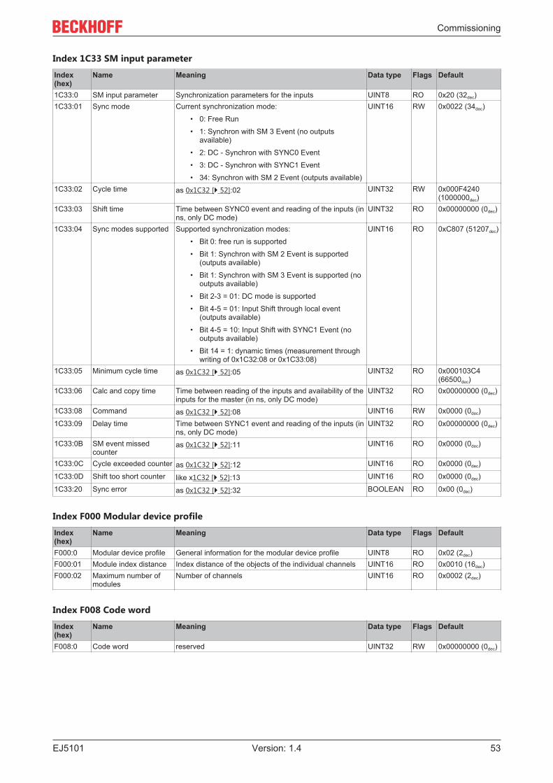
Commissioning
EJ5101 53Version: 1.4
Index 1C33 SM input parameter
Index(hex)
Name Meaning Data type Flags Default
1C33:0 SM input parameter Synchronization parameters for the inputs UINT8 RO 0x20 (32dec)1C33:01 Sync mode Current synchronization mode:
• 0: Free Run
• 1: Synchron with SM 3 Event (no outputsavailable)
• 2: DC - Synchron with SYNC0 Event
• 3: DC - Synchron with SYNC1 Event
• 34: Synchron with SM 2 Event (outputs available)
UINT16 RW 0x0022 (34dec)
1C33:02 Cycle time as 0x1C32 [} 52]:02 UINT32 RW 0x000F4240(1000000dec)
1C33:03 Shift time Time between SYNC0 event and reading of the inputs (inns, only DC mode)
UINT32 RO 0x00000000 (0dec)
1C33:04 Sync modes supported Supported synchronization modes:
• Bit 0: free run is supported
• Bit 1: Synchron with SM 2 Event is supported(outputs available)
• Bit 1: Synchron with SM 3 Event is supported (nooutputs available)
• Bit 2-3 = 01: DC mode is supported
• Bit 4-5 = 01: Input Shift through local event(outputs available)
• Bit 4-5 = 10: Input Shift with SYNC1 Event (nooutputs available)
• Bit 14 = 1: dynamic times (measurement throughwriting of 0x1C32:08 or 0x1C33:08)
UINT16 RO 0xC807 (51207dec)
1C33:05 Minimum cycle time as 0x1C32 [} 52]:05 UINT32 RO 0x000103C4(66500dec)
1C33:06 Calc and copy time Time between reading of the inputs and availability of theinputs for the master (in ns, only DC mode)
UINT32 RO 0x00000000 (0dec)
1C33:08 Command as 0x1C32 [} 52]:08 UINT16 RW 0x0000 (0dec)
1C33:09 Delay time Time between SYNC1 event and reading of the inputs (inns, only DC mode)
UINT32 RO 0x00000000 (0dec)
1C33:0B SM event missedcounter
as 0x1C32 [} 52]:11 UINT16 RO 0x0000 (0dec)
1C33:0C Cycle exceeded counter as 0x1C32 [} 52]:12 UINT16 RO 0x0000 (0dec)
1C33:0D Shift too short counter like x1C32 [} 52]:13 UINT16 RO 0x0000 (0dec)
1C33:20 Sync error as 0x1C32 [} 52]:32 BOOLEAN RO 0x00 (0dec)
Index F000 Modular device profile
Index(hex)
Name Meaning Data type Flags Default
F000:0 Modular device profile General information for the modular device profile UINT8 RO 0x02 (2dec)F000:01 Module index distance Index distance of the objects of the individual channels UINT16 RO 0x0010 (16dec)F000:02 Maximum number of
modulesNumber of channels UINT16 RO 0x0002 (2dec)
Index F008 Code word
Index(hex)
Name Meaning Data type Flags Default
F008:0 Code word reserved UINT32 RW 0x00000000 (0dec)

Commissioning
EJ510154 Version: 1.4
Index F010 Module list
Index(hex)
Name Meaning Data type Flags Default
F010:0 Module list Maximum subindex UINT8 RW 0x02 (2dec)F010:01 SubIndex 001 reserved UINT32 RW 0x000001FE
(510dec)F010:02 SubIndex 002 reserved UINT32 RW 0x000001FF
(511dec)

Appendix
EJ5101 55Version: 1.4
7 Appendix
7.1 Support and ServiceBeckhoff and their partners around the world offer comprehensive support and service, making available fastand competent assistance with all questions related to Beckhoff products and system solutions.
Beckhoff's branch offices and representatives
Please contact your Beckhoff branch office or representative for local support and service on Beckhoffproducts!
The addresses of Beckhoff's branch offices and representatives round the world can be found on her internetpages: https://www.beckhoff.com
You will also find further documentation for Beckhoff components there.
Beckhoff Support
Support offers you comprehensive technical assistance, helping you not only with the application ofindividual Beckhoff products, but also with other, wide-ranging services:
• support• design, programming and commissioning of complex automation systems• and extensive training program for Beckhoff system components
Hotline: +49 5246 963 157Fax: +49 5246 963 9157e-mail: [email protected]
Beckhoff Service
The Beckhoff Service Center supports you in all matters of after-sales service:
• on-site service• repair service• spare parts service• hotline service
Hotline: +49 5246 963 460Fax: +49 5246 963 479e-mail: [email protected]
Beckhoff Headquarters
Beckhoff Automation GmbH & Co. KG
Huelshorstweg 2033415 VerlGermany
Phone: +49 5246 963 0Fax: +49 5246 963 198e-mail: [email protected]: https://www.beckhoff.com


Beckhoff Automation GmbH & Co. KGHülshorstweg 2033415 VerlGermanyPhone: +49 5246 [email protected]
More Information: www.beckhoff.com/EJ5101