pressure measuring modules - em37xx - download - beckhoff
TRANSCRIPT

Documentation | EN
Pressure Measuring ModulesEM37xx
2021-07-02 | Version: 1.4


Table of contents
Pressure Measuring Modules 3Version: 1.4
Table of contents1 Foreword .................................................................................................................................................... 5
1.1 Product overview Pressure Measuring Terminal ............................................................................... 51.2 Notes on the documentation.............................................................................................................. 51.3 Safety instructions ............................................................................................................................. 61.4 Documentation issue status .............................................................................................................. 71.5 Version identification of EtherCAT devices ....................................................................................... 7
1.5.1 Beckhoff Identification Code (BIC)................................................................................... 10
2 EM37xx - Product description ................................................................................................................ 122.1 EM3701 - Introduction ..................................................................................................................... 122.2 EM3702 - Introduction ..................................................................................................................... 132.3 EM3712 - Introduction ..................................................................................................................... 142.4 Quick links ....................................................................................................................................... 142.5 Technical data ................................................................................................................................. 15
3 Basics communication ........................................................................................................................... 163.1 EtherCAT basics.............................................................................................................................. 163.2 EtherCAT cabling – wire-bound....................................................................................................... 163.3 General notes for setting the watchdog........................................................................................... 173.4 EtherCAT State Machine................................................................................................................. 193.5 CoE Interface................................................................................................................................... 203.6 Distributed Clock ............................................................................................................................. 25
4 Mounting and wiring................................................................................................................................ 264.1 Instructions for ESD protection........................................................................................................ 264.2 Recommended mounting rails ......................................................................................................... 264.3 Mounting and demounting - terminals with front unlocking ............................................................. 264.4 Installation positions ........................................................................................................................ 284.5 Positioning of passive Terminals ..................................................................................................... 314.6 UL notice ......................................................................................................................................... 314.7 LED displays.................................................................................................................................... 334.8 Connection ...................................................................................................................................... 34
5 Commissioning........................................................................................................................................ 355.1 TwinCAT Quick Start ....................................................................................................................... 35
5.1.1 TwinCAT 2 ....................................................................................................................... 385.1.2 TwinCAT 3 ....................................................................................................................... 48
5.2 TwinCAT Development Environment .............................................................................................. 615.2.1 Installation of the TwinCAT real-time driver..................................................................... 625.2.2 Notes regarding ESI device description........................................................................... 675.2.3 TwinCAT ESI Updater ..................................................................................................... 715.2.4 Distinction between Online and Offline............................................................................ 715.2.5 OFFLINE configuration creation ...................................................................................... 725.2.6 ONLINE configuration creation ........................................................................................ 775.2.7 EtherCAT subscriber configuration.................................................................................. 855.2.8 Import/Export of EtherCAT devices with SCI and XTI ..................................................... 94
5.3 General Notes - EtherCAT Slave Application................................................................................ 100

Table of contents
Pressure Measuring Modules4 Version: 1.4
6 EM37xx - Commissioning ..................................................................................................................... 1086.1 Basic function principles ................................................................................................................ 1086.2 Application examples..................................................................................................................... 111
6.2.1 EM3701 - application examples..................................................................................... 1116.2.2 EM3702 - application example: pneumatic systems...................................................... 1136.2.3 EM3712 - Application example Packaging plant for eggs ............................................. 113
6.3 Process data and settings ............................................................................................................. 1146.3.1 Parameterization EM37xx ............................................................................................. 1146.3.2 Process data.................................................................................................................. 1156.3.3 Data stream ................................................................................................................... 1176.3.4 Settings.......................................................................................................................... 1186.3.5 Calculation of process data ........................................................................................... 120
6.4 Object description and parameterization ....................................................................................... 1216.4.1 Restore object................................................................................................................ 1216.4.2 Configuration data ......................................................................................................... 1216.4.3 Configuration data (vendor-specific).............................................................................. 1226.4.4 Input data....................................................................................................................... 1226.4.5 Command object............................................................................................................ 1226.4.6 Information / diagnosis data .......................................................................................... 1236.4.7 Standard objects............................................................................................................ 123
6.5 Notices on analog specifications ................................................................................................... 1266.5.1 Full scale value (FSV).................................................................................................... 1266.5.2 Measuring error/ measurement deviation ...................................................................... 127
7 Appendix ................................................................................................................................................ 1287.1 EtherCAT AL Status Codes........................................................................................................... 1287.2 Firmware compatibility ................................................................................................................... 1287.3 Firmware Update EL/ES/EM/ELM/EPxxxx .................................................................................... 128
7.3.1 Device description ESI file/XML..................................................................................... 1307.3.2 Firmware explanation .................................................................................................... 1337.3.3 Updating controller firmware *.efw................................................................................. 1347.3.4 FPGA firmware *.rbf....................................................................................................... 1357.3.5 Simultaneous updating of several EtherCAT devices.................................................... 139
7.4 Restoring the delivery state ........................................................................................................... 1407.5 Support and Service ...................................................................................................................... 141

Foreword
Pressure Measuring Modules 5Version: 1.4
1 Foreword
1.1 Product overview Pressure Measuring TerminalEM3701 [} 12] Single channel differential pressure measuring module (-100 hPa to +100 hPa)
EM3702 [} 13] Dual channel relative pressure measuring module (0 hPa to 7500 hPa)
EM3712 [} 14] Dual channel relative pressure measuring module (-1000 hPa to +1000 hPa)
1.2 Notes on the documentationThis description is only intended for the use of trained specialists in control and automation engineering whoare familiar with the applicable national standards.It is essential that the following notes and explanations are followed when installing and commissioningthese components.
The responsible staff must ensure that the application or use of the products described satisfy all therequirements for safety, including all the relevant laws, regulations, guidelines and standards.
Disclaimer
The documentation has been prepared with care. The products described are, however, constantly underdevelopment.For that reason the documentation is not in every case checked for consistency with performance data,standards or other characteristics.In the event that it contains technical or editorial errors, we retain the right to make alterations at any timeand without warning.No claims for the modification of products that have already been supplied may be made on the basis of thedata, diagrams and descriptions in this documentation.
Trademarks
Beckhoff®, TwinCAT®, EtherCAT®, Safety over EtherCAT®, TwinSAFE®, XFC®and XTS® are registeredtrademarks of and licensed by Beckhoff Automation GmbH.Other designations used in this publication may be trademarks whose use by third parties for their ownpurposes could violate the rights of the owners.
Patent Pending
The EtherCAT Technology is covered, including but not limited to the following patent applications andpatents:EP1590927, EP1789857, DE102004044764, DE102007017835with corresponding applications or registrations in various other countries.
The TwinCAT Technology is covered, including but not limited to the following patent applications andpatents:EP0851348, US6167425 with corresponding applications or registrations in various other countries.
Copyright
© Beckhoff Automation GmbH & Co. KG, Germany.The reproduction, distribution and utilization of this document as well as the communication of its contents toothers without express authorization are prohibited.Offenders will be held liable for the payment of damages. All rights reserved in the event of the grant of apatent, utility model or design.

Foreword
Pressure Measuring Modules6 Version: 1.4
1.3 Safety instructions
Safety regulations
Please note the following safety instructions and explanations!Product-specific safety instructions can be found on following pages or in the areas mounting, wiring,commissioning etc.
Exclusion of liability
All the components are supplied in particular hardware and software configurations appropriate for theapplication. Modifications to hardware or software configurations other than those described in thedocumentation are not permitted, and nullify the liability of Beckhoff Automation GmbH & Co. KG.
Personnel qualification
This description is only intended for trained specialists in control, automation and drive engineering who arefamiliar with the applicable national standards.
Description of instructions
In this documentation the following instructions are used. These instructions must be read carefully and followed without fail!
DANGERSerious risk of injury!Failure to follow this safety instruction directly endangers the life and health of persons.
WARNINGRisk of injury!Failure to follow this safety instruction endangers the life and health of persons.
CAUTIONPersonal injuries!Failure to follow this safety instruction can lead to injuries to persons.
NOTEDamage to environment/equipment or data lossFailure to follow this instruction can lead to environmental damage, equipment damage or data loss.
Tip or pointerThis symbol indicates information that contributes to better understanding.

Foreword
Pressure Measuring Modules 7Version: 1.4
1.4 Documentation issue statusVersion Comment1.4 • New front pate
• Update revision status• Update structure
1.3 • Update chapter “UL notice”• Update chapter “Firmware compatibility”• Update structure
1.2 • Update chapter "Notes on the documentation"• Update chapter "Technical data"• Addenda chapter "Instructions for ESD protection"• Chapter “Analog technical notices - specifications” replaced by chapter “Notices on
analog specifications”• Addenda chapter "UL notice"• Update revision status
1.1 • EM3712 added• Update title page• Addenda temperature coefficient in chapter "Analog technical notices - specifications"• Update chapter "EtherCAT AL Status Codes"• Update chapter "TwinCAT 2.1x" -> "TwinCAT Development Environment"• "TwinCAT Quick Start" added
1.0 • Documentation recreated
1.5 Version identification of EtherCAT devices
Designation
A Beckhoff EtherCAT device has a 14-digit designation, made up of
• family key• type• version• revision
Example Family Type Version RevisionEL3314-0000-0016 EL terminal
(12 mm, non-pluggable connectionlevel)
3314 (4-channel thermocoupleterminal)
0000 (basic type) 0016
ES3602-0010-0017 ES terminal(12 mm, pluggableconnection level)
3602 (2-channel voltagemeasurement)
0010 (high-precision version)
0017
CU2008-0000-0000 CU device 2008 (8-port fast ethernet switch) 0000 (basic type) 0000
Notes• The elements mentioned above result in the technical designation. EL3314-0000-0016 is used in the
example below.• EL3314-0000 is the order identifier, in the case of “-0000” usually abbreviated to EL3314. “-0016” is the
EtherCAT revision.

Foreword
Pressure Measuring Modules8 Version: 1.4
• The order identifier is made up of- family key (EL, EP, CU, ES, KL, CX, etc.)- type (3314)- version (-0000)
• The revision -0016 shows the technical progress, such as the extension of features with regard to theEtherCAT communication, and is managed by Beckhoff.In principle, a device with a higher revision can replace a device with a lower revision, unless specifiedotherwise, e.g. in the documentation.Associated and synonymous with each revision there is usually a description (ESI, EtherCAT SlaveInformation) in the form of an XML file, which is available for download from the Beckhoff web site. From 2014/01 the revision is shown on the outside of the IP20 terminals, see Fig. “EL5021 EL terminal,standard IP20 IO device with batch number and revision ID (since 2014/01)”.
• The type, version and revision are read as decimal numbers, even if they are technically saved inhexadecimal.
Identification number
Beckhoff EtherCAT devices from the different lines have different kinds of identification numbers:
Production lot/batch number/serial number/date code/D number
The serial number for Beckhoff IO devices is usually the 8-digit number printed on the device or on a sticker.The serial number indicates the configuration in delivery state and therefore refers to a whole productionbatch, without distinguishing the individual modules of a batch.
Structure of the serial number: KK YY FF HH
KK - week of production (CW, calendar week)YY - year of productionFF - firmware versionHH - hardware version
Example with Ser. no.: 12063A02: 12 - production week 12 06 - production year 2006 3A - firmware version 3A 02 -hardware version 02
Exceptions can occur in the IP67 area, where the following syntax can be used (see respective devicedocumentation):
Syntax: D ww yy x y z u
D - prefix designationww - calendar weekyy - yearx - firmware version of the bus PCBy - hardware version of the bus PCBz - firmware version of the I/O PCBu - hardware version of the I/O PCB
Example: D.22081501 calendar week 22 of the year 2008 firmware version of bus PCB: 1 hardware versionof bus PCB: 5 firmware version of I/O PCB: 0 (no firmware necessary for this PCB) hardware version of I/OPCB: 1
Unique serial number/ID, ID number
In addition, in some series each individual module has its own unique serial number.
See also the further documentation in the area
• IP67: EtherCAT Box
• Safety: TwinSafe• Terminals with factory calibration certificate and other measuring terminals

Foreword
Pressure Measuring Modules 9Version: 1.4
Examples of markings
Fig. 1: EL5021 EL terminal, standard IP20 IO device with serial/ batch number and revision ID (since2014/01)
Fig. 2: EK1100 EtherCAT coupler, standard IP20 IO device with serial/ batch number
Fig. 3: EL3202-0020 with serial/ batch number 26131006 and unique ID-number 204418

Foreword
Pressure Measuring Modules10 Version: 1.4
1.5.1 Beckhoff Identification Code (BIC)The Beckhoff Identification Code (BIC) is increasingly being applied to Beckhoff products to uniquely identifythe product. The BIC is represented as a Data Matrix Code (DMC, code scheme ECC200), the content isbased on the ANSI standard MH10.8.2-2016.
Fig. 4: BIC as data matrix code (DMC, code scheme ECC200)
The BIC will be introduced step by step across all product groups.
Depending on the product, it can be found in the following places:
• on the packaging unit• directly on the product (if space suffices)• on the packaging unit and the product
The BIC is machine-readable and contains information that can also be used by the customer for handlingand product management.
Each piece of information can be uniquely identified using the so-called data identifier(ANSI MH10.8.2-2016). The data identifier is followed by a character string. Both together have a maximumlength according to the table below. If the information is shorter, spaces are added to it. The data underpositions 1 to 4 are always available.
The following information is contained:

Foreword
Pressure Measuring Modules 11Version: 1.4
Itemno.
Type ofinformation
Explanation Dataidentifier
Number of digitsincl. data identifier
Example
1 Beckhoff ordernumber
Beckhoff order number 1P 8 1P072222
2 Beckhoff TraceabilityNumber (BTN)
Unique serial number,see note below
S 12 SBTNk4p562d7
3 Article description Beckhoff articledescription, e.g.EL1008
1K 32 1KEL1809
4 Quantity Quantity in packagingunit, e.g. 1, 10, etc.
Q 6 Q1
5 Batch number Optional: Year and weekof production
2P 14 2P401503180016
6 ID/serial number Optional: Present-dayserial number system,e.g. with safety productsor calibrated terminals
51S 12 51S678294104
7 Variant number Optional: Product variantnumber on the basis ofstandard products
30P 32 30PF971, 2*K183
...
Further types of information and data identifiers are used by Beckhoff and serve internal processes.
Structure of the BIC
Example of composite information from item 1 to 4 and 6. The data identifiers are marked in red for betterdisplay:
BTN
An important component of the BIC is the Beckhoff Traceability Number (BTN, item no. 2). The BTN is aunique serial number consisting of eight characters that will replace all other serial number systems atBeckhoff in the long term (e.g. batch designations on IO components, previous serial number range forsafety products, etc.). The BTN will also be introduced step by step, so it may happen that the BTN is not yetcoded in the BIC.
NOTEThis information has been carefully prepared. However, the procedure described is constantly being furtherdeveloped. We reserve the right to revise and change procedures and documentation at any time and with-out prior notice. No claims for changes can be made from the information, illustrations and descriptions inthis information.

EM37xx - Product description
Pressure Measuring Modules12 Version: 1.4
2 EM37xx - Product description
2.1 EM3701 - Introduction
Fig. 5: EM3701 Top view
Single channel differential pressure measuring module
The EM3701 differential pressure measuring module enables direct measurement of pressure differencesbetween two hose connections. The pressure difference is available in the fieldbus as a 16 bit value in therange between -100 hPa to +100 hPa (-100 mbar to +100 mbar). The status LEDs indicate proper function orerrors such as overrange.

EM37xx - Product description
Pressure Measuring Modules 13Version: 1.4
2.2 EM3702 - Introduction
Fig. 6: EM3702 Top view
Dual channel relative pressure measuring module for 0 to 7500 hPa (0 to 7.5 bar)
The EM3702 relative pressure measuring module enables direct measurement of two pressure values at thehose connections. The pressure is determined as a pressure difference to the ambiance of the EM3702 andis available in the fieldbus as a 16 bit value. The status LEDs indicate proper function or errors such asoverrange.

EM37xx - Product description
Pressure Measuring Modules14 Version: 1.4
2.3 EM3712 - Introduction
Fig. 7: EM3712 Top view
Dual channel relative pressure measuring module for -1000 hPa to +1000 hPa (-1 bar to +1 bar)
The relative pressure measuring module EM3712 allows the direct measurement of two negative pressurevalues on the hose connections. The pressure is determined as the difference to the environment of theEM3712 and is available in the field bus with 16 bit resolution. The status LEDs indicate proper function orerrors such as range exceedance.
2.4 Quick links• Mounting and wiring [} 26]
• Process data and settings [} 114]
• Application examples [} 111]
• Object description and parameterization [} 121]

EM37xx - Product description
Pressure Measuring Modules 15Version: 1.4
2.5 Technical dataTechnical data EM3701-0000 EM3702-0000 EM3712-0000Number of inputs 1 2 2Technology Differential pressure
measurementRelative pressuremeasurement
Relative pressuremeasurement
Measuring range -100 hPa to +100 hPa(-100 mbar to +100 mbar)
0 hPa to 7500 hPa(0 bar to 7.5 bar)
-1000 hPa to +1000 hPa(-1 bar to +1 bar)
Permissibleoverpressure
max. ±500 hPa differential max. +10,000 hPa +5000 hPa
permissible media non-aggressive gasesResolution 0.1 hPa (0.1 mbar) per digit 1 hPa (1 mbar) per digit 1 hPa (1 mbar) per digitMeasurement error ±3% (of the full scale value)Measuring speed typically 4 msPressure connectors screwing plug [} 34], M12 x 1Power supply for theelectronics
via the E-bus
Current consumptionvia E-bus
70 mA 60 mA 70 mAThe pre-calculated maximum E-Bus current [} 16] is displayed in the TwinCATSystem Manager as a column value.
Electrical isolation 500 V (E-bus/signal voltage)Bit width in processimage
2 bytes status, 2 bytes value per channel
Dimensions withouttubes (w x h x d)
approx. 26,5 mm x 100 mm x 52 mm (width aligned: 24 mm)
Weight approx. 95 gPermissible ambienttemperature rangeduring operation
0°C ... + 55°C
Permissible ambienttemperature rangeduring storage
-25°C ... + 85°C
Permissible relativehumidity
95 %, no condensation
Assembly on a 35 mm mounting rail [} 26] (e.g. DIN rail TH 35-7.5 conforming to EN 60715)Vibration/shockresistance
conforms to EN 60068-2-6 / EN 60068-2-27, EN 60068-2-29
EMC immunity/emission
conforms to EN 61000-6-2 / EN 61000-6-4
Protection class IP20Installation position variableApproval CE,
cULus [} 31]

Basics communication
Pressure Measuring Modules16 Version: 1.4
3 Basics communication
3.1 EtherCAT basicsPlease refer to the EtherCAT System Documentation for the EtherCAT fieldbus basics.
3.2 EtherCAT cabling – wire-boundThe cable length between two EtherCAT devices must not exceed 100 m. This results from the FastEthernettechnology, which, above all for reasons of signal attenuation over the length of the cable, allows a maximumlink length of 5 + 90 + 5 m if cables with appropriate properties are used. See also the Designrecommendations for the infrastructure for EtherCAT/Ethernet.
Cables and connectors
For connecting EtherCAT devices only Ethernet connections (cables + plugs) that meet the requirements ofat least category 5 (CAt5) according to EN 50173 or ISO/IEC 11801 should be used. EtherCAT uses 4 wiresfor signal transfer.
EtherCAT uses RJ45 plug connectors, for example. The pin assignment is compatible with the Ethernetstandard (ISO/IEC 8802-3).
Pin Color of conductor Signal Description1 yellow TD + Transmission Data +2 orange TD - Transmission Data -3 white RD + Receiver Data +6 blue RD - Receiver Data -
Due to automatic cable detection (auto-crossing) symmetric (1:1) or cross-over cables can be used betweenEtherCAT devices from Beckhoff.
Recommended cablesIt is recommended to use the appropriate Beckhoff components e.g.- cable sets ZK1090-9191-xxxx respectively- RJ45 connector, field assembly ZS1090-0005- EtherCAT cable, field assembly ZB9010, ZB9020
Suitable cables for the connection of EtherCAT devices can be found on the Beckhoff website!
E-Bus supply
A bus coupler can supply the EL terminals added to it with the E-bus system voltage of 5 V; a coupler isthereby loadable up to 2 A as a rule (see details in respective device documentation).Information on how much current each EL terminal requires from the E-bus supply is available online and inthe catalogue. If the added terminals require more current than the coupler can supply, then power feedterminals (e.g. EL9410) must be inserted at appropriate places in the terminal strand.
The pre-calculated theoretical maximum E-Bus current is displayed in the TwinCAT System Manager. Ashortfall is marked by a negative total amount and an exclamation mark; a power feed terminal is to beplaced before such a position.

Basics communication
Pressure Measuring Modules 17Version: 1.4
Fig. 8: System manager current calculation
NOTEMalfunction possible!The same ground potential must be used for the E-Bus supply of all EtherCAT terminals in a terminal block!
3.3 General notes for setting the watchdogELxxxx terminals are equipped with a safety feature (watchdog) that switches off the outputs after aspecifiable time e.g. in the event of an interruption of the process data traffic, depending on the device andsettings, e.g. in OFF state.
The EtherCAT slave controller (ESC) in the EL2xxx terminals features two watchdogs:
• SM watchdog (default: 100 ms)• PDI watchdog (default: 100 ms)
SM watchdog (SyncManager Watchdog)
The SyncManager watchdog is reset after each successful EtherCAT process data communication with theterminal. If no EtherCAT process data communication takes place with the terminal for longer than the setand activated SM watchdog time, e.g. in the event of a line interruption, the watchdog is triggered and theoutputs are set to FALSE. The OP state of the terminal is unaffected. The watchdog is only reset after asuccessful EtherCAT process data access. Set the monitoring time as described below.
The SyncManager watchdog monitors correct and timely process data communication with the ESC from theEtherCAT side.
PDI watchdog (Process Data Watchdog)
If no PDI communication with the EtherCAT slave controller (ESC) takes place for longer than the set andactivated PDI watchdog time, this watchdog is triggered.PDI (Process Data Interface) is the internal interface between the ESC and local processors in the EtherCATslave, for example. The PDI watchdog can be used to monitor this communication for failure.
The PDI watchdog monitors correct and timely process data communication with the ESC from theapplication side.
The settings of the SM- and PDI-watchdog must be done for each slave separately in the TwinCAT SystemManager.

Basics communication
Pressure Measuring Modules18 Version: 1.4
Fig. 9: EtherCAT tab -> Advanced Settings -> Behavior -> Watchdog
Notes:
• the multiplier is valid for both watchdogs.• each watchdog has its own timer setting, the outcome of this in summary with the multiplier is a
resulting time.• Important: the multiplier/timer setting is only loaded into the slave at the start up, if the checkbox is
activated.If the checkbox is not activated, nothing is downloaded and the ESC settings remain unchanged.
Multiplier
Both watchdogs receive their pulses from the local terminal cycle, divided by the watchdog multiplier:
1/25 MHz * (watchdog multiplier + 2) = 100 µs (for default setting of 2498 for the multiplier)
The standard setting of 1000 for the SM watchdog corresponds to a release time of 100 ms.
The value in multiplier + 2 corresponds to the number of basic 40 ns ticks representing a watchdog tick.The multiplier can be modified in order to adjust the watchdog time over a larger range.
Example “Set SM watchdog”
This checkbox enables manual setting of the watchdog times. If the outputs are set and the EtherCATcommunication is interrupted, the SM watchdog is triggered after the set time and the outputs are erased.This setting can be used for adapting a terminal to a slower EtherCAT master or long cycle times. Thedefault SM watchdog setting is 100 ms. The setting range is 0...65535. Together with a multiplier with arange of 1...65535 this covers a watchdog period between 0...~170 seconds.

Basics communication
Pressure Measuring Modules 19Version: 1.4
Calculation
Multiplier = 2498 → watchdog base time = 1 / 25 MHz * (2498 + 2) = 0.0001 seconds = 100 µsSM watchdog = 10000 → 10000 * 100 µs = 1 second watchdog monitoring time
CAUTIONUndefined state possible!The function for switching off of the SM watchdog via SM watchdog = 0 is only implemented in terminalsfrom version -0016. In previous versions this operating mode should not be used.
CAUTIONDamage of devices and undefined state possible!If the SM watchdog is activated and a value of 0 is entered the watchdog switches off completely. This isthe deactivation of the watchdog! Set outputs are NOT set in a safe state, if the communication is inter-rupted.
3.4 EtherCAT State MachineThe state of the EtherCAT slave is controlled via the EtherCAT State Machine (ESM). Depending upon thestate, different functions are accessible or executable in the EtherCAT slave. Specific commands must besent by the EtherCAT master to the device in each state, particularly during the bootup of the slave.
A distinction is made between the following states:
• Init• Pre-Operational• Safe-Operational and• Operational• Boot
The regular state of each EtherCAT slave after bootup is the OP state.
Fig. 10: States of the EtherCAT State Machine

Basics communication
Pressure Measuring Modules20 Version: 1.4
Init
After switch-on the EtherCAT slave in the Init state. No mailbox or process data communication is possible.The EtherCAT master initializes sync manager channels 0 and 1 for mailbox communication.
Pre-Operational (Pre-Op)
During the transition between Init and Pre-Op the EtherCAT slave checks whether the mailbox was initializedcorrectly.
In Pre-Op state mailbox communication is possible, but not process data communication. The EtherCATmaster initializes the sync manager channels for process data (from sync manager channel 2), the FMMUchannels and, if the slave supports configurable mapping, PDO mapping or the sync manager PDOassignment. In this state the settings for the process data transfer and perhaps terminal-specific parametersthat may differ from the default settings are also transferred.
Safe-Operational (Safe-Op)
During transition between Pre-Op and Safe-Op the EtherCAT slave checks whether the sync managerchannels for process data communication and, if required, the distributed clocks settings are correct. Beforeit acknowledges the change of state, the EtherCAT slave copies current input data into the associated DP-RAM areas of the EtherCAT slave controller (ECSC).
In Safe-Op state mailbox and process data communication is possible, although the slave keeps its outputsin a safe state, while the input data are updated cyclically.
Outputs in SAFEOP stateThe default set watchdog [} 17] monitoring sets the outputs of the module in a safe state - depend-ing on the settings in SAFEOP and OP - e.g. in OFF state. If this is prevented by deactivation of thewatchdog monitoring in the module, the outputs can be switched or set also in the SAFEOP state.
Operational (Op)
Before the EtherCAT master switches the EtherCAT slave from Safe-Op to Op it must transfer valid outputdata.
In the Op state the slave copies the output data of the masters to its outputs. Process data and mailboxcommunication is possible.
Boot
In the Boot state the slave firmware can be updated. The Boot state can only be reached via the Init state.
In the Boot state mailbox communication via the file access over EtherCAT (FoE) protocol is possible, but noother mailbox communication and no process data communication.
3.5 CoE Interface
General description
The CoE interface (CAN application protocol over EtherCAT)) is used for parameter management ofEtherCAT devices. EtherCAT slaves or the EtherCAT master manage fixed (read only) or variableparameters which they require for operation, diagnostics or commissioning.
CoE parameters are arranged in a table hierarchy. In principle, the user has read access via the fieldbus.The EtherCAT master (TwinCAT System Manager) can access the local CoE lists of the slaves viaEtherCAT in read or write mode, depending on the attributes.

Basics communication
Pressure Measuring Modules 21Version: 1.4
Different CoE parameter types are possible, including string (text), integer numbers, Boolean values or largerbyte fields. They can be used to describe a wide range of features. Examples of such parameters includemanufacturer ID, serial number, process data settings, device name, calibration values for analogmeasurement or passwords.
The order is specified in two levels via hexadecimal numbering: (main)index, followed by subindex. Thevalue ranges are
• Index: 0x0000 …0xFFFF (0...65535dez)• SubIndex: 0x00…0xFF (0...255dez)
A parameter localized in this way is normally written as 0x8010:07, with preceding “0x” to identify thehexadecimal numerical range and a colon between index and subindex.
The relevant ranges for EtherCAT fieldbus users are:
• 0x1000: This is where fixed identity information for the device is stored, including name, manufacturer,serial number etc., plus information about the current and available process data configurations.
• 0x8000: This is where the operational and functional parameters for all channels are stored, such asfilter settings or output frequency.
Other important ranges are:
• 0x4000: here are the channel parameters for some EtherCAT devices. Historically, this was the firstparameter area before the 0x8000 area was introduced. EtherCAT devices that were previouslyequipped with parameters in 0x4000 and changed to 0x8000 support both ranges for compatibilityreasons and mirror internally.
• 0x6000: Input PDOs (“input” from the perspective of the EtherCAT master)• 0x7000: Output PDOs (“output” from the perspective of the EtherCAT master)
AvailabilityNot every EtherCAT device must have a CoE list. Simple I/O modules without dedicated processorusually have no variable parameters and therefore no CoE list.
If a device has a CoE list, it is shown in the TwinCAT System Manager as a separate tab with a listing of theelements:
Fig. 11: “CoE Online” tab

Basics communication
Pressure Measuring Modules22 Version: 1.4
The figure above shows the CoE objects available in device “EL2502”, ranging from 0x1000 to 0x1600. Thesubindices for 0x1018 are expanded.
Data management and function “NoCoeStorage”
Some parameters, particularly the setting parameters of the slave, are configurable and writeable. This canbe done in write or read mode
• via the System Manager (Fig. “CoE Online” tab) by clickingThis is useful for commissioning of the system/slaves. Click on the row of the index to beparameterized and enter a value in the “SetValue” dialog.
• from the control system/PLC via ADS, e.g. through blocks from the TcEtherCAT.lib libraryThis is recommended for modifications while the system is running or if no System Manager oroperating staff are available.
Data managementIf slave CoE parameters are modified online, Beckhoff devices store any changes in a fail-safemanner in the EEPROM, i.e. the modified CoE parameters are still available after a restart. The situation may be different with other manufacturers.
An EEPROM is subject to a limited lifetime with respect to write operations. From typically 100,000write operations onwards it can no longer be guaranteed that new (changed) data are reliably savedor are still readable. This is irrelevant for normal commissioning. However, if CoE parameters arecontinuously changed via ADS at machine runtime, it is quite possible for the lifetime limit to bereached. Support for the NoCoeStorage function, which suppresses the saving of changed CoE val-ues, depends on the firmware version.Please refer to the technical data in this documentation as to whether this applies to the respectivedevice.• If the function is supported: the function is activated by entering the code word 0x12345678 once
in CoE 0xF008 and remains active as long as the code word is not changed. After switching thedevice on it is then inactive. Changed CoE values are not saved in the EEPROM and can thusbe changed any number of times.
• Function is not supported: continuous changing of CoE values is not permissible in view of thelifetime limit.
Startup listChanges in the local CoE list of the terminal are lost if the terminal is replaced. If a terminal is re-placed with a new Beckhoff terminal, it will have the default settings. It is therefore advisable to linkall changes in the CoE list of an EtherCAT slave with the Startup list of the slave, which is pro-cessed whenever the EtherCAT fieldbus is started. In this way a replacement EtherCAT slave canautomatically be parameterized with the specifications of the user.If EtherCAT slaves are used which are unable to store local CoE values permanently, the Startuplist must be used.
Recommended approach for manual modification of CoE parameters• Make the required change in the System Manager
The values are stored locally in the EtherCAT slave• If the value is to be stored permanently, enter it in the Startup list.
The order of the Startup entries is usually irrelevant.

Basics communication
Pressure Measuring Modules 23Version: 1.4
Fig. 12: Startup list in the TwinCAT System Manager
The Startup list may already contain values that were configured by the System Manager based on the ESIspecifications. Additional application-specific entries can be created.
Online/offline list
While working with the TwinCAT System Manager, a distinction has to be made whether the EtherCATdevice is “available”, i.e. switched on and linked via EtherCAT and therefore online, or whether aconfiguration is created offline without connected slaves.
In both cases a CoE list as shown in Fig. “CoE online tab” is displayed. The connectivity is shown as offline/online.
• If the slave is offline◦ The offline list from the ESI file is displayed. In this case modifications are not meaningful or
possible.◦ The configured status is shown under Identity.◦ No firmware or hardware version is displayed, since these are features of the physical device.◦ Offline is shown in red.
Fig. 13: Offline list

Basics communication
Pressure Measuring Modules24 Version: 1.4
• If the slave is online◦ The actual current slave list is read. This may take several seconds, depending on the size and
cycle time.◦ The actual identity is displayed◦ The firmware and hardware version of the equipment according to the electronic information is
displayed◦ Online is shown in green.
Fig. 14: Online list
Channel-based order
The CoE list is available in EtherCAT devices that usually feature several functionally equivalent channels.For example, a 4-channel analog 0...10 V input terminal also has four logical channels and therefore fouridentical sets of parameter data for the channels. In order to avoid having to list each channel in thedocumentation, the placeholder “n” tends to be used for the individual channel numbers.
In the CoE system 16 indices, each with 255 subindices, are generally sufficient for representing all channelparameters. The channel-based order is therefore arranged in 16dec/10hex steps. The parameter range0x8000 exemplifies this:
• Channel 0: parameter range 0x8000:00 ... 0x800F:255• Channel 1: parameter range 0x8010:00 ... 0x801F:255• Channel 2: parameter range 0x8020:00 ... 0x802F:255• ...
This is generally written as 0x80n0.
Detailed information on the CoE interface can be found in the EtherCAT system documentation on theBeckhoff website.

Basics communication
Pressure Measuring Modules 25Version: 1.4
3.6 Distributed ClockThe distributed clock represents a local clock in the EtherCAT slave controller (ESC) with the followingcharacteristics:
• Unit 1 ns• Zero point 1.1.2000 00:00• Size 64 bit (sufficient for the next 584 years; however, some EtherCAT slaves only offer 32-bit support,
i.e. the variable overflows after approx. 4.2 seconds)• The EtherCAT master automatically synchronizes the local clock with the master clock in the EtherCAT
bus with a precision of < 100 ns.
For detailed information please refer to the EtherCAT system description.

Mounting and wiring
Pressure Measuring Modules26 Version: 1.4
4 Mounting and wiring
4.1 Instructions for ESD protectionNOTE
Destruction of the devices by electrostatic discharge possible!The devices contain components at risk from electrostatic discharge caused by improper handling.• Please ensure you are electrostatically discharged and avoid touching the contacts of the device directly.• Avoid contact with highly insulating materials (synthetic fibers, plastic film etc.).• Surroundings (working place, packaging and personnel) should by grounded probably, when handling
with the devices.
• Each assembly must be terminated at the right hand end with an EL9011 or EL9012 bus end cap, to en-sure the protection class and ESD protection.
Fig. 15: Spring contacts of the Beckhoff I/O components
4.2 Recommended mounting railsTerminal Modules and EtherCAT Modules of KMxxxx and EMxxxx series, same as the terminals of theEL66xx and EL67xx series can be snapped onto the following recommended mounting rails:
• DIN Rail TH 35-7.5 with 1 mm material thickness (according to EN 60715)• DIN Rail TH 35-15 with 1,5 mm material thickness
Pay attention to the material thickness of the DIN RailTerminal Modules und EtherCAT Modules of KMxxxx and EMxxxx series, same as the terminals ofthe EL66xx and EL67xx series does not fit to the DIN Rail TH 35-15 with 2,2 to 2,5 mm materialthickness (according to EN 60715)!
4.3 Mounting and demounting - terminals with frontunlocking
The terminal modules are fastened to the assembly surface with the aid of a 35 mm mounting rail (e.g.mounting rail TH 35-15).

Mounting and wiring
Pressure Measuring Modules 27Version: 1.4
Fixing of mounting railsThe locking mechanism of the terminals and couplers extends to the profile of the mounting rail. Atthe installation, the locking mechanism of the components must not come into conflict with the fixingbolts of the mounting rail. To mount the recommended mounting rails under the terminals and cou-plers, you should use flat mounting connections (e.g. countersunk screws or blind rivets).
WARNINGRisk of electric shock and damage of device!Bring the bus terminal system into a safe, powered down state before starting installation, disassembly orwiring of the Bus Terminals!
Mounting• Fit the mounting rail to the planned assembly location.
and press (1) the terminal module against the mounting rail until it latches in place on the mountingrail (2).
• Attach the cables.
Demounting• Remove all the cables.• Lever the unlatching hook back with thumb and forefinger (3). An internal mechanism pulls the two
latching lugs (3a) from the top hat rail back into the terminal module.

Mounting and wiring
Pressure Measuring Modules28 Version: 1.4
• Pull (4) the terminal module away from the mounting surface. Avoid canting of the module; you should stabilize the module with the other hand, if required.
4.4 Installation positionsNOTE
Constraints regarding installation position and operating temperature rangePlease refer to the technical data for a terminal to ascertain whether any restrictions regarding the installa-tion position and/or the operating temperature range have been specified. When installing high power dissi-pation terminals ensure that an adequate spacing is maintained between other components above and be-low the terminal in order to guarantee adequate ventilation!
Optimum installation position (standard)
The optimum installation position requires the mounting rail to be installed horizontally and the connectionsurfaces of the EL/KL terminals to face forward (see Fig. Recommended distances for standard installationposition). The terminals are ventilated from below, which enables optimum cooling of the electronics throughconvection. “From below” is relative to the acceleration of gravity.

Mounting and wiring
Pressure Measuring Modules 29Version: 1.4
Fig. 16: Recommended distances for standard installation position
Compliance with the distances shown in Fig. Recommended distances for standard installation position isrecommended.
Other installation positions
All other installation positions are characterized by different spatial arrangement of the mounting rail - seeFig Other installation positions.
The minimum distances to ambient specified above also apply to these installation positions.

Mounting and wiring
Pressure Measuring Modules30 Version: 1.4
Fig. 17: Other installation positions

Mounting and wiring
Pressure Measuring Modules 31Version: 1.4
4.5 Positioning of passive TerminalsHint for positioning of passive terminals in the bus terminal blockEtherCAT Terminals (ELxxxx / ESxxxx), which do not take an active part in data transfer within thebus terminal block are so called passive terminals. The passive terminals have no current consump-tion out of the E-Bus. To ensure an optimal data transfer, you must not directly string together more than two passive ter-minals!
Examples for positioning of passive terminals (highlighted)
Fig. 18: Correct positioning
Fig. 19: Incorrect positioning
4.6 UL noticeApplicationBeckhoff EtherCAT modules are intended for use with Beckhoff’s UL Listed EtherCAT Sys-tem only.
ExaminationFor cULus examination, the Beckhoff I/O System has only been investigated for risk of fireand electrical shock (in accordance with UL508 and CSA C22.2 No. 142).

Mounting and wiring
Pressure Measuring Modules32 Version: 1.4
For devices with Ethernet connectorsNot for connection to telecommunication circuits.
Basic principles
UL certification according to UL508. Devices with this kind of certification are marked by this sign:

Mounting and wiring
Pressure Measuring Modules 33Version: 1.4
4.7 LED displays
EM3701
Fig. 20: EM3701 Top view
LED DisplayRun (green) off Data communication on the E-Bus is not active
on Data transmission on the E-Bus is activeOverrange (red) on The differential pressure is above the permitted measuring range [} 15]Underrange (red) on The differential pressure is below the permitted measuring range [} 15]

Mounting and wiring
Pressure Measuring Modules34 Version: 1.4
EM3702, EM3712
Fig. 21: LEDs, taking the EM3702 as an example
LED DisplayRun (green) off Data transmission on the E-bus is not active
on Data transmission on the E-bus is activeError X1 (red) on The pressure at connection X1 is below (under-range) or above (over-range)
the permitted measuring range [} 15]Error X2 (red) on The pressure at connection X2 is below (under-range) or above (over-range)
the permitted measuring range [} 15]
4.8 ConnectionThe air hoses are connected to push-in fittings.
Technical Data Threaded push-in fittingType QSS-4-FOuter hose diameter 4 mmNominal diameter 2.6 mmThread M12 x 1Width across flats 14 mm

Commissioning
Pressure Measuring Modules 35Version: 1.4
5 Commissioning
5.1 TwinCAT Quick StartTwinCAT is a development environment for real-time control including multi-PLC system, NC axis control,programming and operation. The whole system is mapped through this environment and enables access to aprogramming environment (including compilation) for the controller. Individual digital or analog inputs oroutputs can also be read or written directly, in order to verify their functionality, for example.
For further information please refer to http://infosys.beckhoff.com:
• EtherCAT Systemmanual:Fieldbus Components → EtherCAT Terminals → EtherCAT System Documentation → Setup in theTwinCAT System Manager
• TwinCAT 2 → TwinCAT System Manager → I/O - Configuration• In particular, TwinCAT driver installation:
Fieldbus components → Fieldbus Cards and Switches → FC900x – PCI Cards for Ethernet →Installation
Devices contain the terminals for the actual configuration. All configuration data can be entered directly viaeditor functions (offline) or via the “Scan” function (online):
• “offline”: The configuration can be customized by adding and positioning individual components.These can be selected from a directory and configured.
◦ The procedure for offline mode can be found under http://infosys.beckhoff.com:TwinCAT 2 → TwinCAT System Manager → IO - Configuration → Adding an I/O Device
• “online”: The existing hardware configuration is read
◦ See also http://infosys.beckhoff.com:Fieldbus components → Fieldbus cards and switches → FC900x – PCI Cards for Ethernet →Installation → Searching for devices
The following relationship is envisaged from user PC to the individual control elements:

Commissioning
Pressure Measuring Modules36 Version: 1.4
Fig. 22: Relationship between user side (commissioning) and installation
The user inserting of certain components (I/O device, terminal, box...) is the same in TwinCAT 2 andTwinCAT 3. The descriptions below relate to the online procedure.
Sample configuration (actual configuration)
Based on the following sample configuration, the subsequent subsections describe the procedure forTwinCAT 2 and TwinCAT 3:
• Control system (PLC) CX2040 including CX2100-0004 power supply unit• Connected to the CX2040 on the right (E-bus):
EL1004 (4-channel digital input terminal 24 VDC)• Linked via the X001 port (RJ-45): EK1100 EtherCAT Coupler• Connected to the EK1100 EtherCAT coupler on the right (E-bus):
EL2008 (8-channel digital output terminal 24 VDC; 0.5 A)• (Optional via X000: a link to an external PC for the user interface)

Commissioning
Pressure Measuring Modules 37Version: 1.4
Fig. 23: Control configuration with Embedded PC, input (EL1004) and output (EL2008)
Note that all combinations of a configuration are possible; for example, the EL1004 terminal could also beconnected after the coupler, or the EL2008 terminal could additionally be connected to the CX2040 on theright, in which case the EK1100 coupler wouldn’t be necessary.

Commissioning
Pressure Measuring Modules38 Version: 1.4
5.1.1 TwinCAT 2
Startup
TwinCAT basically uses two user interfaces: the TwinCAT System Manager for communication with theelectromechanical components and TwinCAT PLC Control for the development and compilation of acontroller. The starting point is the TwinCAT System Manager.
After successful installation of the TwinCAT system on the PC to be used for development, the TwinCAT 2System Manager displays the following user interface after startup:
Fig. 24: Initial TwinCAT 2 user interface
Generally, TwinCAT can be used in local or remote mode. Once the TwinCAT system including the userinterface (standard) is installed on the respective PLC, TwinCAT can be used in local mode and thereby thenext step is “Insert Device [} 40]”.
If the intention is to address the TwinCAT runtime environment installed on a PLC as developmentenvironment remotely from another system, the target system must be made known first. In the menu under
“Actions” → “Choose Target System...”, via the symbol “ ” or the “F8” key, open the following window:

Commissioning
Pressure Measuring Modules 39Version: 1.4
Fig. 25: Selection of the target system
Use “Search (Ethernet)...” to enter the target system. Thus a next dialog opens to either:
• enter the known computer name after “Enter Host Name / IP:” (as shown in red)• perform a “Broadcast Search” (if the exact computer name is not known)• enter the known computer IP or AmsNetID.
Fig. 26: Specify the PLC for access by the TwinCAT System Manager: selection of the target system
Once the target system has been entered, it is available for selection as follows (a password may have to beentered):
After confirmation with “OK” the target system can be accessed via the System Manager.

Commissioning
Pressure Measuring Modules40 Version: 1.4
Adding devices
In the configuration tree of the TwinCAT 2 System Manager user interface on the left, select “I/O Devices”and then right-click to open a context menu and select “Scan Devices…”, or start the action in the menu bar
via . The TwinCAT System Manager may first have to be set to “Config mode” via or via menu“Actions” → “Set/Reset TwinCAT to Config Mode…” (Shift + F4).
Fig. 27: Select “Scan Devices...”
Confirm the warning message, which follows, and select “EtherCAT” in the dialog:
Fig. 28: Automatic detection of I/O devices: selection the devices to be integrated
Confirm the message “Find new boxes”, in order to determine the terminals connected to the devices. “FreeRun” enables manipulation of input and output values in “Config mode” and should also be acknowledged.
Based on the sample configuration [} 36] described at the beginning of this section, the result is as follows:

Commissioning
Pressure Measuring Modules 41Version: 1.4
Fig. 29: Mapping of the configuration in the TwinCAT 2 System Manager
The whole process consists of two stages, which may be performed separately (first determine the devices,then determine the connected elements such as boxes, terminals, etc.). A scan can also be initiated byselecting “Device ...” from the context menu, which then reads the elements present in the configurationbelow:
Fig. 30: Reading of individual terminals connected to a device
This functionality is useful if the actual configuration is modified at short notice.
Programming and integrating the PLC
TwinCAT PLC Control is the development environment for the creation of the controller in different programenvironments: TwinCAT PLC Control supports all languages described in IEC 61131-3. There are two text-based languages and three graphical languages.
• Text-based languages◦ Instruction List (IL)

Commissioning
Pressure Measuring Modules42 Version: 1.4
◦ Structured Text (ST)• Graphical languages
◦ Function Block Diagram (FBD)◦ Ladder Diagram (LD)◦ The Continuous Function Chart Editor (CFC)◦ Sequential Function Chart (SFC)
The following section refers to Structured Text (ST).
After starting TwinCAT PLC Control, the following user interface is shown for an initial project:
Fig. 31: TwinCAT PLC Control after startup
Sample variables and a sample program have been created and stored under the name “PLC_example.pro”:

Commissioning
Pressure Measuring Modules 43Version: 1.4
Fig. 32: Sample program with variables after a compile process (without variable integration)
Warning 1990 (missing “VAR_CONFIG”) after a compile process indicates that the variables defined asexternal (with the ID “AT%I*” or “AT%Q*”) have not been assigned. After successful compilation, TwinCATPLC Control creates a “*.tpy” file in the directory in which the project was stored. This file (“*.tpy”) containsvariable assignments and is not known to the System Manager, hence the warning. Once the SystemManager has been notified, the warning no longer appears.
First, integrate the TwinCAT PLC Control project in the System Manager via the context menu of the PLCconfiguration; right-click and select “Append PLC Project…”:
Fig. 33: Appending the TwinCAT PLC Control project

Commissioning
Pressure Measuring Modules44 Version: 1.4
Select the PLC configuration “PLC_example.tpy” in the browser window that opens. The project including thetwo variables identified with “AT” are then integrated in the configuration tree of the System Manager:
Fig. 34: PLC project integrated in the PLC configuration of the System Manager
The two variables “bEL1004_Ch4” and “nEL2008_value” can now be assigned to certain process objects ofthe I/O configuration.
Assigning variables
Open a window for selecting a suitable process object (PDO) via the context menu of a variable of theintegrated project “PLC_example” and via “Modify Link...” “Standard”:
Fig. 35: Creating the links between PLC variables and process objects
In the window that opens, the process object for the variable “bEL1004_Ch4” of type BOOL can be selectedfrom the PLC configuration tree:

Commissioning
Pressure Measuring Modules 45Version: 1.4
Fig. 36: Selecting PDO of type BOOL
According to the default setting, certain PDO objects are now available for selection. In this sample the inputof channel 4 of the EL1004 terminal is selected for linking. In contrast, the checkbox “All types” must beticked for creating the link for the output variables, in order to allocate a set of eight separate output bits to abyte variable. The following diagram shows the whole process:
Fig. 37: Selecting several PDOs simultaneously: activate “Continuous” and “All types”
Note that the “Continuous” checkbox was also activated. This is designed to allocate the bits contained in thebyte of the variable “nEL2008_value” sequentially to all eight selected output bits of the EL2008 terminal. Inthis way it is possible to subsequently address all eight outputs of the terminal in the program with a bytecorresponding to bit 0 for channel 1 to bit 7 for channel 8 of the PLC. A special symbol ( ) at the yellow orred object of the variable indicates that a link exists. The links can also be checked by selecting a “Goto LinkVariable” from the context menu of a variable. The object opposite, in this case the PDO, is automaticallyselected:

Commissioning
Pressure Measuring Modules46 Version: 1.4
Fig. 38: Application of a “Goto Link” variable, using “MAIN.bEL1004_Ch4” as a sample
The process of assigning variables to the PDO is completed via the menu selection “Actions” → “Generate
Mappings”, key Ctrl+M or by clicking on the symbol in the menu.
This can be visualized in the configuration:
The process of creating links can also take place in the opposite direction, i.e. starting with individual PDOsto variable. However, in this example it would then not be possible to select all output bits for the EL2008,since the terminal only makes individual digital outputs available. If a terminal has a byte, word, integer orsimilar PDO, it is possible to allocate this a set of bit-standardized variables (type “BOOL”). Here, too, a“Goto Link Variable” from the context menu of a PDO can be executed in the other direction, so that therespective PLC instance can then be selected.
Activation of the configuration
The allocation of PDO to PLC variables has now established the connection from the controller to the inputsand outputs of the terminals. The configuration can now be activated. First, the configuration can be verified
via (or via “Actions” → “Check Configuration”). If no error is present, the configuration can be
activated via (or via “Actions” → “Activate Configuration…”) to transfer the System Manager settingsto the runtime system. Confirm the messages “Old configurations are overwritten!” and “Restart TwinCATsystem in Run mode” with “OK”.
A few seconds later the real-time status is displayed at the bottom right in the System Manager.The PLC system can then be started as described below.
Starting the controller
Starting from a remote system, the PLC control has to be linked with the Embedded PC over Ethernet via“Online” → “Choose Run-Time System…”:

Commissioning
Pressure Measuring Modules 47Version: 1.4
Fig. 39: Choose target system (remote)
In this sample “Runtime system 1 (port 801)” is selected and confirmed. Link the PLC with the real-time
system via menu option “Online” → “Login”, the F11 key or by clicking on the symbol . The controlprogram can then be loaded for execution. This results in the message “No program on the controller!Should the new program be loaded?”, which should be acknowledged with “Yes”. The runtime environmentis ready for the program start:

Commissioning
Pressure Measuring Modules48 Version: 1.4
Fig. 40: PLC Control logged in, ready for program startup
The PLC can now be started via “Online” → “Run”, F5 key or .
5.1.2 TwinCAT 3
Startup
TwinCAT makes the development environment areas available together with Microsoft Visual Studio: afterstartup, the project folder explorer appears on the left in the general window area (cf. “TwinCAT SystemManager” of TwinCAT 2) for communication with the electromechanical components.
After successful installation of the TwinCAT system on the PC to be used for development, TwinCAT 3(shell) displays the following user interface after startup:

Commissioning
Pressure Measuring Modules 49Version: 1.4
Fig. 41: Initial TwinCAT 3 user interface
First create a new project via (or under “File”→“New”→ “Project…”). In thefollowing dialog make the corresponding entries as required (as shown in the diagram):
Fig. 42: Create new TwinCAT project
The new project is then available in the project folder explorer:

Commissioning
Pressure Measuring Modules50 Version: 1.4
Fig. 43: New TwinCAT3 project in the project folder explorer
Generally, TwinCAT can be used in local or remote mode. Once the TwinCAT system including the userinterface (standard) is installed on the respective PLC, TwinCAT can be used in local mode and thereby thenext step is “Insert Device [} 51]”.
If the intention is to address the TwinCAT runtime environment installed on a PLC as developmentenvironment remotely from another system, the target system must be made known first. Via the symbol inthe menu bar:
expand the pull-down menu:
and open the following window:
Fig. 44: Selection dialog: Choose the target system

Commissioning
Pressure Measuring Modules 51Version: 1.4
Use “Search (Ethernet)...” to enter the target system. Thus a next dialog opens to either:
• enter the known computer name after “Enter Host Name / IP:” (as shown in red)• perform a “Broadcast Search” (if the exact computer name is not known)• enter the known computer IP or AmsNetID.
Fig. 45: Specify the PLC for access by the TwinCAT System Manager: selection of the target system
Once the target system has been entered, it is available for selection as follows (a password may have to beentered):
After confirmation with “OK” the target system can be accessed via the Visual Studio shell.
Adding devices
In the project folder explorer of the Visual Studio shell user interface on the left, select “Devices” within
element “I/O”, then right-click to open a context menu and select “Scan” or start the action via in the
menu bar. The TwinCAT System Manager may first have to be set to “Config mode” via or via themenu “TwinCAT” → “Restart TwinCAT (Config mode)”.
Fig. 46: Select “Scan”
Confirm the warning message, which follows, and select “EtherCAT” in the dialog:

Commissioning
Pressure Measuring Modules52 Version: 1.4
Fig. 47: Automatic detection of I/O devices: selection the devices to be integrated
Confirm the message “Find new boxes”, in order to determine the terminals connected to the devices. “FreeRun” enables manipulation of input and output values in “Config mode” and should also be acknowledged.
Based on the sample configuration [} 36] described at the beginning of this section, the result is as follows:
Fig. 48: Mapping of the configuration in VS shell of the TwinCAT3 environment
The whole process consists of two stages, which may be performed separately (first determine the devices,then determine the connected elements such as boxes, terminals, etc.). A scan can also be initiated byselecting “Device ...” from the context menu, which then reads the elements present in the configurationbelow:

Commissioning
Pressure Measuring Modules 53Version: 1.4
Fig. 49: Reading of individual terminals connected to a device
This functionality is useful if the actual configuration is modified at short notice.
Programming the PLC
TwinCAT PLC Control is the development environment for the creation of the controller in different programenvironments: TwinCAT PLC Control supports all languages described in IEC 61131-3. There are two text-based languages and three graphical languages.
• Text-based languages◦ Instruction List (IL)◦ Structured Text (ST)
• Graphical languages◦ Function Block Diagram (FBD)◦ Ladder Diagram (LD)◦ The Continuous Function Chart Editor (CFC)◦ Sequential Function Chart (SFC)
The following section refers to Structured Text (ST).
In order to create a programming environment, a PLC subproject is added to the project sample via thecontext menu of “PLC” in the project folder explorer by selecting “Add New Item….”:

Commissioning
Pressure Measuring Modules54 Version: 1.4
Fig. 50: Adding the programming environment in “PLC”
In the dialog that opens select “Standard PLC project” and enter “PLC_example” as project name, forexample, and select a corresponding directory:
Fig. 51: Specifying the name and directory for the PLC programming environment
The “Main” program, which already exists by selecting “Standard PLC project”, can be opened by double-clicking on “PLC_example_project” in “POUs”. The following user interface is shown for an initial project:

Commissioning
Pressure Measuring Modules 55Version: 1.4
Fig. 52: Initial “Main” program of the standard PLC project
To continue, sample variables and a sample program have now been created:

Commissioning
Pressure Measuring Modules56 Version: 1.4
Fig. 53: Sample program with variables after a compile process (without variable integration)
The control program is now created as a project folder, followed by the compile process:
Fig. 54: Start program compilation
The following variables, identified in the ST/ PLC program with “AT%”, are then available in under“Assignments” in the project folder explorer:
Assigning variables
Via the menu of an instance - variables in the “PLC” context, use the “Modify Link…” option to open awindow for selecting a suitable process object (PDO) for linking:

Commissioning
Pressure Measuring Modules 57Version: 1.4
Fig. 55: Creating the links between PLC variables and process objects
In the window that opens, the process object for the variable “bEL1004_Ch4” of type BOOL can be selectedfrom the PLC configuration tree:
Fig. 56: Selecting PDO of type BOOL
According to the default setting, certain PDO objects are now available for selection. In this sample the inputof channel 4 of the EL1004 terminal is selected for linking. In contrast, the checkbox “All types” must beticked for creating the link for the output variables, in order to allocate a set of eight separate output bits to abyte variable. The following diagram shows the whole process:

Commissioning
Pressure Measuring Modules58 Version: 1.4
Fig. 57: Selecting several PDOs simultaneously: activate “Continuous” and “All types”
Note that the “Continuous” checkbox was also activated. This is designed to allocate the bits contained in thebyte of the variable “nEL2008_value” sequentially to all eight selected output bits of the EL2008 terminal. Inthis way it is possible to subsequently address all eight outputs of the terminal in the program with a bytecorresponding to bit 0 for channel 1 to bit 7 for channel 8 of the PLC. A special symbol ( ) at the yellow orred object of the variable indicates that a link exists. The links can also be checked by selecting a “Goto LinkVariable” from the context menu of a variable. The object opposite, in this case the PDO, is automaticallyselected:
Fig. 58: Application of a “Goto Link” variable, using “MAIN.bEL1004_Ch4” as a sample
The process of creating links can also take place in the opposite direction, i.e. starting with individual PDOsto variable. However, in this example it would then not be possible to select all output bits for the EL2008,since the terminal only makes individual digital outputs available. If a terminal has a byte, word, integer or

Commissioning
Pressure Measuring Modules 59Version: 1.4
similar PDO, it is possible to allocate this a set of bit-standardized variables (type “BOOL”). Here, too, a“Goto Link Variable” from the context menu of a PDO can be executed in the other direction, so that therespective PLC instance can then be selected.
Note on the type of variable assignmentThe following type of variable assignment can only be used from TwinCAT version V3.1.4024.4 on-wards and is only available for terminals with a microcontroller.
In TwinCAT it is possible to create a structure from the mapped process data of a terminal. An instance ofthis structure can then be created in the PLC, so it is possible to access the process data directly from thePLC without having to declare own variables.
The procedure for the EL3001 1-channel analog input terminal -10...+10 V is shown as an example.
1. First the required process data must be selected in the “Process data” tab in TwinCAT.2. After that, the PLC data type must be generated in the tab “PLC” via the check box.3. The data type in the “Data Type” field can then be copied using the “Copy” button.
Fig. 59: Creating a PLC data type
4. An instance of the data structure of the copied data type must then be created in the PLC.
Fig. 60: Instance_of_struct
5. Then the project folder must be created. This can be done either via the key combination “CTRL +Shift + B” or via the “Build” tab in TwinCAT.
6. The structure in the “PLC” tab of the terminal must then be linked to the created instance.

Commissioning
Pressure Measuring Modules60 Version: 1.4
Fig. 61: Linking the structure
7. In the PLC the process data can then be read or written via the structure in the program code.
Fig. 62: Reading a variable from the structure of the process data
Activation of the configuration
The allocation of PDO to PLC variables has now established the connection from the controller to the inputs
and outputs of the terminals. The configuration can now be activated with or via the menu under“TwinCAT” in order to transfer settings of the development environment to the runtime system. Confirm themessages “Old configurations are overwritten!” and “Restart TwinCAT system in Run mode” with “OK”. Thecorresponding assignments can be seen in the project folder explorer:
A few seconds later the corresponding status of the Run mode is displayed in the form of a rotating symbol
at the bottom right of the VS shell development environment. The PLC system can then be started asdescribed below.

Commissioning
Pressure Measuring Modules 61Version: 1.4
Starting the controller
Select the menu option “PLC” → “Login” or click on to link the PLC with the real-time system and loadthe control program for execution. This results in the message No program on the controller! Should the newprogram be loaded?, which should be acknowledged with “Yes”. The runtime environment is ready for
program start by click on symbol , the “F5” key or via “PLC” in the menu selecting “Start”. The startedprogramming environment shows the runtime values of individual variables:
Fig. 63: TwinCAT development environment (VS shell): logged-in, after program startup
The two operator control elements for stopping and logout result in the required action(accordingly also for stop “Shift + F5”, or both actions can be selected via the PLC menu).
5.2 TwinCAT Development EnvironmentThe Software for automation TwinCAT (The Windows Control and Automation Technology) will bedistinguished into:
• TwinCAT 2: System Manager (Configuration) & PLC Control (Programming)• TwinCAT 3: Enhancement of TwinCAT 2 (Programming and Configuration takes place via a common
Development Environment)
Details:• TwinCAT 2:
◦ Connects I/O devices to tasks in a variable-oriented manner◦ Connects tasks to tasks in a variable-oriented manner◦ Supports units at the bit level◦ Supports synchronous or asynchronous relationships◦ Exchange of consistent data areas and process images◦ Datalink on NT - Programs by open Microsoft Standards (OLE, OCX, ActiveX, DCOM+, etc.)

Commissioning
Pressure Measuring Modules62 Version: 1.4
◦ Integration of IEC 61131-3-Software-SPS, Software- NC and Software-CNC within WindowsNT/2000/XP/Vista, Windows 7, NT/XP Embedded, CE
◦ Interconnection to all common fieldbusses
◦ More…
Additional features:• TwinCAT 3 (eXtended Automation):
◦ Visual-Studio®-Integration◦ Choice of the programming language◦ Supports object orientated extension of IEC 61131-3◦ Usage of C/C++ as programming language for real time applications◦ Connection to MATLAB®/Simulink®◦ Open interface for expandability◦ Flexible run-time environment◦ Active support of Multi-Core- und 64-Bit-Operatingsystem◦ Automatic code generation and project creation with the TwinCAT Automation Interface
◦ More…
Within the following sections commissioning of the TwinCAT Development Environment on a PC System forthe control and also the basically functions of unique control elements will be explained.
Please see further information to TwinCAT 2 and TwinCAT 3 at http://infosys.beckhoff.com.
5.2.1 Installation of the TwinCAT real-time driverIn order to assign real-time capability to a standard Ethernet port of an IPC controller, the Beckhoff real-timedriver has to be installed on this port under Windows.
This can be done in several ways. One option is described here.
In the System Manager call up the TwinCAT overview of the local network interfaces via Options → ShowReal Time Ethernet Compatible Devices.
Fig. 64: System Manager “Options” (TwinCAT 2)
This have to be called up by the Menü “TwinCAT” within the TwinCAT 3 environment:
Fig. 65: Call up under VS Shell (TwinCAT 3)

Commissioning
Pressure Measuring Modules 63Version: 1.4
The following dialog appears:
Fig. 66: Overview of network interfaces
Interfaces listed under “Compatible devices” can be assigned a driver via the “Install” button. A driver shouldonly be installed on compatible devices.
A Windows warning regarding the unsigned driver can be ignored.
Alternatively an EtherCAT-device can be inserted first of all as described in chapter Offline configurationcreation, section “Creating the EtherCAT device” [} 72] in order to view the compatible ethernet ports via itsEtherCAT properties (tab “Adapter”, button “Compatible Devices…”):
Fig. 67: EtherCAT device properties(TwinCAT 2): click on “Compatible Devices…” of tab “Adapte””
TwinCAT 3: the properties of the EtherCAT device can be opened by double click on “Device .. (EtherCAT)”within the Solution Explorer under “I/O”:
After the installation the driver appears activated in the Windows overview for the network interface(Windows Start → System Properties → Network)

Commissioning
Pressure Measuring Modules64 Version: 1.4
Fig. 68: Windows properties of the network interface
A correct setting of the driver could be:
Fig. 69: Exemplary correct driver setting for the Ethernet port
Other possible settings have to be avoided:

Commissioning
Pressure Measuring Modules 65Version: 1.4
Fig. 70: Incorrect driver settings for the Ethernet port

Commissioning
Pressure Measuring Modules66 Version: 1.4
IP address of the port used
IP address/DHCPIn most cases an Ethernet port that is configured as an EtherCAT device will not transport generalIP packets. For this reason and in cases where an EL6601 or similar devices are used it is useful tospecify a fixed IP address for this port via the “Internet Protocol TCP/IP” driver setting and to disableDHCP. In this way the delay associated with the DHCP client for the Ethernet port assigning itself adefault IP address in the absence of a DHCP server is avoided. A suitable address space is192.168.x.x, for example.
Fig. 71: TCP/IP setting for the Ethernet port

Commissioning
Pressure Measuring Modules 67Version: 1.4
5.2.2 Notes regarding ESI device description
Installation of the latest ESI device description
The TwinCAT EtherCAT master/System Manager needs the device description files for the devices to beused in order to generate the configuration in online or offline mode. The device descriptions are containedin the so-called ESI files (EtherCAT Slave Information) in XML format. These files can be requested from therespective manufacturer and are made available for download. An *.xml file may contain several devicedescriptions.
The ESI files for Beckhoff EtherCAT devices are available on the Beckhoff website.
The ESI files should be stored in the TwinCAT installation directory.
Default settings:
• TwinCAT 2: C:\TwinCAT\IO\EtherCAT• TwinCAT 3: C:\TwinCAT\3.1\Config\Io\EtherCAT
The files are read (once) when a new System Manager window is opened, if they have changed since thelast time the System Manager window was opened.
A TwinCAT installation includes the set of Beckhoff ESI files that was current at the time when the TwinCATbuild was created.
For TwinCAT 2.11/TwinCAT 3 and higher, the ESI directory can be updated from the System Manager, if theprogramming PC is connected to the Internet; by
• TwinCAT 2: Option → “Update EtherCAT Device Descriptions”• TwinCAT 3: TwinCAT → EtherCAT Devices → “Update Device Descriptions (via ETG Website)…”
The TwinCAT ESI Updater [} 71] is available for this purpose.
ESIThe *.xml files are associated with *.xsd files, which describe the structure of the ESI XML files. Toupdate the ESI device descriptions, both file types should therefore be updated.
Device differentiation
EtherCAT devices/slaves are distinguished by four properties, which determine the full device identifier. Forexample, the device identifier EL2521-0025-1018 consists of:
• family key “EL”• name “2521”• type “0025”• and revision “1018”
Fig. 72: Identifier structure
The order identifier consisting of name + type (here: EL2521-0010) describes the device function. Therevision indicates the technical progress and is managed by Beckhoff. In principle, a device with a higherrevision can replace a device with a lower revision, unless specified otherwise, e.g. in the documentation.Each revision has its own ESI description. See further notes [} 7].

Commissioning
Pressure Measuring Modules68 Version: 1.4
Online description
If the EtherCAT configuration is created online through scanning of real devices (see section Online setup)and no ESI descriptions are available for a slave (specified by name and revision) that was found, theSystem Manager asks whether the description stored in the device should be used. In any case, the SystemManager needs this information for setting up the cyclic and acyclic communication with the slave correctly.
Fig. 73: OnlineDescription information window (TwinCAT 2)
In TwinCAT 3 a similar window appears, which also offers the Web update:
Fig. 74: Information window OnlineDescription (TwinCAT 3)
If possible, the Yes is to be rejected and the required ESI is to be requested from the device manufacturer.After installation of the XML/XSD file the configuration process should be repeated.
NOTEChanging the “usual” configuration through a scanü If a scan discovers a device that is not yet known to TwinCAT, distinction has to be made between two
cases. Taking the example here of the EL2521-0000 in the revision 1019a) no ESI is present for the EL2521-0000 device at all, either for the revision 1019 or for an older revision.
The ESI must then be requested from the manufacturer (in this case Beckhoff).b) an ESI is present for the EL2521-0000 device, but only in an older revision, e.g. 1018 or 1017.
In this case an in-house check should first be performed to determine whether the spare parts stock al-lows the integration of the increased revision into the configuration at all. A new/higher revision usuallyalso brings along new features. If these are not to be used, work can continue without reservations withthe previous revision 1018 in the configuration. This is also stated by the Beckhoff compatibility rule.
Refer in particular to the chapter “General notes on the use of Beckhoff EtherCAT IO components” and formanual configuration to the chapter “Offline configuration creation [} 72]”.
If the OnlineDescription is used regardless, the System Manager reads a copy of the device description fromthe EEPROM in the EtherCAT slave. In complex slaves the size of the EEPROM may not be sufficient for thecomplete ESI, in which case the ESI would be incomplete in the configurator. Therefore it’s recommendedusing an offline ESI file with priority in such a case.
The System Manager creates for online recorded device descriptions a new file“OnlineDescription0000...xml” in its ESI directory, which contains all ESI descriptions that were read online.

Commissioning
Pressure Measuring Modules 69Version: 1.4
Fig. 75: File OnlineDescription.xml created by the System Manager
Is a slave desired to be added manually to the configuration at a later stage, online created slaves areindicated by a prepended symbol “>” in the selection list (see Figure Indication of an online recorded ESI ofEL2521 as an example).
Fig. 76: Indication of an online recorded ESI of EL2521 as an example
If such ESI files are used and the manufacturer's files become available later, the file OnlineDescription.xmlshould be deleted as follows:
• close all System Manager windows• restart TwinCAT in Config mode• delete “OnlineDescription0000...xml”• restart TwinCAT System Manager
This file should not be visible after this procedure, if necessary press <F5> to update
OnlineDescription for TwinCAT 3.xIn addition to the file described above “OnlineDescription0000...xml”, a so called EtherCAT cachewith new discovered devices is created by TwinCAT 3.x, e.g. under Windows 7:
(Please note the language settings of the OS!)You have to delete this file, too.
Faulty ESI file
If an ESI file is faulty and the System Manager is unable to read it, the System Manager brings up aninformation window.
Fig. 77: Information window for faulty ESI file (left: TwinCAT 2; right: TwinCAT 3)

Commissioning
Pressure Measuring Modules70 Version: 1.4
Reasons may include:
• Structure of the *.xml does not correspond to the associated *.xsd file → check your schematics• Contents cannot be translated into a device description → contact the file manufacturer

Commissioning
Pressure Measuring Modules 71Version: 1.4
5.2.3 TwinCAT ESI UpdaterFor TwinCAT 2.11 and higher, the System Manager can search for current Beckhoff ESI files automatically, ifan online connection is available:
Fig. 78: Using the ESI Updater (>= TwinCAT 2.11)
The call up takes place under:“Options” → “Update EtherCAT Device Descriptions”
Selection under TwinCAT 3:
Fig. 79: Using the ESI Updater (TwinCAT 3)
The ESI Updater (TwinCAT 3) is a convenient option for automatic downloading of ESI data provided byEtherCAT manufacturers via the Internet into the TwinCAT directory (ESI = EtherCAT slave information).TwinCAT accesses the central ESI ULR directory list stored at ETG; the entries can then be viewed in theUpdater dialog, although they cannot be changed there.
The call up takes place under:“TwinCAT” → “EtherCAT Devices” → “Update Device Description (via ETG Website)…”.
5.2.4 Distinction between Online and OfflineThe distinction between online and offline refers to the presence of the actual I/O environment (drives,terminals, EJ-modules). If the configuration is to be prepared in advance of the system configuration as aprogramming system, e.g. on a laptop, this is only possible in “Offline configuration” mode. In this case allcomponents have to be entered manually in the configuration, e.g. based on the electrical design.
If the designed control system is already connected to the EtherCAT system and all components areenergised and the infrastructure is ready for operation, the TwinCAT configuration can simply be generatedthrough “scanning” from the runtime system. This is referred to as online configuration.
In any case, during each startup the EtherCAT master checks whether the slaves it finds match theconfiguration. This test can be parameterised in the extended slave settings. Refer to note “Installation ofthe latest ESI-XML device description” [} 67].
For preparation of a configuration:• the real EtherCAT hardware (devices, couplers, drives) must be present and installed• the devices/modules must be connected via EtherCAT cables or in the terminal/ module strand in the
same way as they are intended to be used later

Commissioning
Pressure Measuring Modules72 Version: 1.4
• the devices/modules be connected to the power supply and ready for communication• TwinCAT must be in CONFIG mode on the target system.
The online scan process consists of:
• detecting the EtherCAT device [} 77] (Ethernet port at the IPC)
• detecting the connected EtherCAT devices [} 78]. This step can be carried out independent of thepreceding step
• troubleshooting [} 81]
The scan with existing configuration [} 82] can also be carried out for comparison.
5.2.5 OFFLINE configuration creation
Creating the EtherCAT device
Create an EtherCAT device in an empty System Manager window.
Fig. 80: Append EtherCAT device (left: TwinCAT 2; right: TwinCAT 3)
Select type “EtherCAT” for an EtherCAT I/O application with EtherCAT slaves. For the present publisher/subscriber service in combination with an EL6601/EL6614 terminal select “EtherCAT Automation Protocolvia EL6601”.
Fig. 81: Selecting the EtherCAT connection (TwinCAT 2.11, TwinCAT 3)
Then assign a real Ethernet port to this virtual device in the runtime system.
Fig. 82: Selecting the Ethernet port

Commissioning
Pressure Measuring Modules 73Version: 1.4
This query may appear automatically when the EtherCAT device is created, or the assignment can be set/modified later in the properties dialog; see Fig. “EtherCAT device properties (TwinCAT 2)”.
Fig. 83: EtherCAT device properties (TwinCAT 2)
TwinCAT 3: the properties of the EtherCAT device can be opened by double click on “Device .. (EtherCAT)”within the Solution Explorer under “I/O”:
Selecting the Ethernet portEthernet ports can only be selected for EtherCAT devices for which the TwinCAT real-time driver isinstalled. This has to be done separately for each port. Please refer to the respective installationpage [} 62].
Defining EtherCAT slaves
Further devices can be appended by right-clicking on a device in the configuration tree.
Fig. 84: Appending EtherCAT devices (left: TwinCAT 2; right: TwinCAT 3)
The dialog for selecting a new device opens. Only devices for which ESI files are available are displayed.
Only devices are offered for selection that can be appended to the previously selected device. Therefore thephysical layer available for this port is also displayed (Fig. “Selection dialog for new EtherCAT device”, A). Inthe case of cable-based Fast-Ethernet physical layer with PHY transfer, then also only cable-based devicesare available, as shown in Fig. “Selection dialog for new EtherCAT device”. If the preceding device hasseveral free ports (e.g. EK1122 or EK1100), the required port can be selected on the right-hand side (A).
Overview of physical layer
• “Ethernet”: cable-based 100BASE-TX: EK couplers, EP boxes, devices with RJ45/M8/M12 connector

Commissioning
Pressure Measuring Modules74 Version: 1.4
• “E-Bus”: LVDS “terminal bus”, “EJ-module”: EL/ES terminals, various modular modules
The search field facilitates finding specific devices (since TwinCAT 2.11 or TwinCAT 3).
Fig. 85: Selection dialog for new EtherCAT device
By default only the name/device type is used as selection criterion. For selecting a specific revision of thedevice the revision can be displayed as “Extended Information”.
Fig. 86: Display of device revision
In many cases several device revisions were created for historic or functional reasons, e.g. throughtechnological advancement. For simplification purposes (see Fig. “Selection dialog for new EtherCATdevice”) only the last (i.e. highest) revision and therefore the latest state of production is displayed in theselection dialog for Beckhoff devices. To show all device revisions available in the system as ESIdescriptions tick the “Show Hidden Devices” check box, see Fig. “Display of previous revisions”.

Commissioning
Pressure Measuring Modules 75Version: 1.4
Fig. 87: Display of previous revisions
Device selection based on revision, compatibilityThe ESI description also defines the process image, the communication type between master andslave/device and the device functions, if applicable. The physical device (firmware, if available) hasto support the communication queries/settings of the master. This is backward compatible, i.e.newer devices (higher revision) should be supported if the EtherCAT master addresses them as anolder revision. The following compatibility rule of thumb is to be assumed for Beckhoff EtherCATTerminals/ Boxes/ EJ-modules:device revision in the system >= device revision in the configurationThis also enables subsequent replacement of devices without changing the configuration (differentspecifications are possible for drives).
Example
If an EL2521-0025-1018 is specified in the configuration, an EL2521-0025-1018 or higher (-1019, -1020) canbe used in practice.
Fig. 88: Name/revision of the terminal
If current ESI descriptions are available in the TwinCAT system, the last revision offered in the selectiondialog matches the Beckhoff state of production. It is recommended to use the last device revision whencreating a new configuration, if current Beckhoff devices are used in the real application. Older revisionsshould only be used if older devices from stock are to be used in the application.
In this case the process image of the device is shown in the configuration tree and can be parameterized asfollows: linking with the task, CoE/DC settings, plug-in definition, startup settings, ...

Commissioning
Pressure Measuring Modules76 Version: 1.4
Fig. 89: EtherCAT terminal in the TwinCAT tree (left: TwinCAT 2; right: TwinCAT 3)

Commissioning
Pressure Measuring Modules 77Version: 1.4
5.2.6 ONLINE configuration creation
Detecting/scanning of the EtherCAT device
The online device search can be used if the TwinCAT system is in CONFIG mode. This can be indicated bya symbol right below in the information bar:
• on TwinCAT 2 by a blue display “Config Mode” within the System Manager window: .
• on TwinCAT 3 within the user interface of the development environment by a symbol .
TwinCAT can be set into this mode:
• TwinCAT 2: by selection of in the Menubar or by “Actions” → “Set/Reset TwinCAT to ConfigMode…”
• TwinCAT 3: by selection of in the Menubar or by “TwinCAT” → “Restart TwinCAT (Config Mode)”
Online scanning in Config modeThe online search is not available in RUN mode (production operation). Note the differentiation be-tween TwinCAT programming system and TwinCAT target system.
The TwinCAT 2 icon ( ) or TwinCAT 3 icon ( ) within the Windows-Taskbar always shows theTwinCAT mode of the local IPC. Compared to that, the System Manager window of TwinCAT 2 or the userinterface of TwinCAT 3 indicates the state of the target system.
Fig. 90: Differentiation local/target system (left: TwinCAT 2; right: TwinCAT 3)
Right-clicking on “I/O Devices” in the configuration tree opens the search dialog.
Fig. 91: Scan Devices (left: TwinCAT 2; right: TwinCAT 3)
This scan mode attempts to find not only EtherCAT devices (or Ethernet ports that are usable as such), butalso NOVRAM, fieldbus cards, SMB etc. However, not all devices can be found automatically.
Fig. 92: Note for automatic device scan (left: TwinCAT 2; right: TwinCAT 3)

Commissioning
Pressure Measuring Modules78 Version: 1.4
Ethernet ports with installed TwinCAT real-time driver are shown as “RT Ethernet” devices. An EtherCATframe is sent to these ports for testing purposes. If the scan agent detects from the response that anEtherCAT slave is connected, the port is immediately shown as an “EtherCAT Device” .
Fig. 93: Detected Ethernet devices
Via respective checkboxes devices can be selected (as illustrated in Fig. “Detected Ethernet devices” e.g.Device 3 and Device 4 were chosen). After confirmation with “OK” a device scan is suggested for all selecteddevices, see Fig.: “Scan query after automatic creation of an EtherCAT device”.
Selecting the Ethernet portEthernet ports can only be selected for EtherCAT devices for which the TwinCAT real-time driver isinstalled. This has to be done separately for each port. Please refer to the respective installationpage [} 62].
Detecting/Scanning the EtherCAT devices
Online scan functionalityDuring a scan the master queries the identity information of the EtherCAT slaves from the slaveEEPROM. The name and revision are used for determining the type. The respective devices are lo-cated in the stored ESI data and integrated in the configuration tree in the default state definedthere.
Fig. 94: Example default state
NOTESlave scanning in practice in series machine productionThe scanning function should be used with care. It is a practical and fast tool for creating an initial configu-ration as a basis for commissioning. In series machine production or reproduction of the plant, however, thefunction should no longer be used for the creation of the configuration, but if necessary for comparison[} 82] with the defined initial configuration.Background: since Beckhoff occasionally increases the revisionversion of the delivered products for product maintenance reasons, a configuration can be created by sucha scan which (with an identical machine construction) is identical according to the device list; however, therespective device revision may differ from the initial configuration.
Example:
Company A builds the prototype of a machine B, which is to be produced in series later on. To do this theprototype is built, a scan of the IO devices is performed in TwinCAT and the initial configuration “B.tsm” iscreated. The EL2521-0025 EtherCAT terminal with the revision 1018 is located somewhere. It is thus builtinto the TwinCAT configuration in this way:

Commissioning
Pressure Measuring Modules 79Version: 1.4
Fig. 95: Installing EthetCAT terminal with revision -1018
Likewise, during the prototype test phase, the functions and properties of this terminal are tested by theprogrammers/commissioning engineers and used if necessary, i.e. addressed from the PLC “B.pro” or theNC. (the same applies correspondingly to the TwinCAT 3 solution files).
The prototype development is now completed and series production of machine B starts, for which Beckhoffcontinues to supply the EL2521-0025-0018. If the commissioning engineers of the series machine productiondepartment always carry out a scan, a B configuration with the identical contents results again for eachmachine. Likewise, A might create spare parts stores worldwide for the coming series-produced machineswith EL2521-0025-1018 terminals.
After some time Beckhoff extends the EL2521-0025 by a new feature C. Therefore the FW is changed,outwardly recognizable by a higher FW version and a new revision -1019. Nevertheless the new devicenaturally supports functions and interfaces of the predecessor version(s); an adaptation of “B.tsm” or even“B.pro” is therefore unnecessary. The series-produced machines can continue to be built with “B.tsm” and“B.pro”; it makes sense to perform a comparative scan [} 82] against the initial configuration “B.tsm” in orderto check the built machine.
However, if the series machine production department now doesn’t use “B.tsm”, but instead carries out ascan to create the productive configuration, the revision -1019 is automatically detected and built into theconfiguration:
Fig. 96: Detection of EtherCAT terminal with revision -1019
This is usually not noticed by the commissioning engineers. TwinCAT cannot signal anything either, sincevirtually a new configuration is created. According to the compatibility rule, however, this means that noEL2521-0025-1018 should be built into this machine as a spare part (even if this nevertheless works in thevast majority of cases).
In addition, it could be the case that, due to the development accompanying production in company A, thenew feature C of the EL2521-0025-1019 (for example, an improved analog filter or an additional processdata for the diagnosis) is discovered and used without in-house consultation. The previous stock of sparepart devices are then no longer to be used for the new configuration “B2.tsm” created in this way. Þ if seriesmachine production is established, the scan should only be performed for informative purposes forcomparison with a defined initial configuration. Changes are to be made with care!
If an EtherCAT device was created in the configuration (manually or through a scan), the I/O field can bescanned for devices/slaves.
Fig. 97: Scan query after automatic creation of an EtherCAT device (left: TwinCAT 2; right: TwinCAT 3)

Commissioning
Pressure Measuring Modules80 Version: 1.4
Fig. 98: Manual triggering of a device scan on a specified EtherCAT device (left: TwinCAT 2; right:TwinCAT 3)
In the System Manager (TwinCAT 2) or the User Interface (TwinCAT 3) the scan process can be monitoredvia the progress bar at the bottom in the status bar.
Fig. 99: Scan progressexemplary by TwinCAT 2
The configuration is established and can then be switched to online state (OPERATIONAL).
Fig. 100: Config/FreeRun query (left: TwinCAT 2; right: TwinCAT 3)
In Config/FreeRun mode the System Manager display alternates between blue and red, and the EtherCATdevice continues to operate with the idling cycle time of 4 ms (default setting), even without active task (NC,PLC).
Fig. 101: Displaying of “Free Run” and “Config Mode” toggling right below in the status bar
Fig. 102: TwinCAT can also be switched to this state by using a button (left: TwinCAT 2; right: TwinCAT 3)
The EtherCAT system should then be in a functional cyclic state, as shown in Fig. Online display example.

Commissioning
Pressure Measuring Modules 81Version: 1.4
Fig. 103: Online display example
Please note:
• all slaves should be in OP state• the EtherCAT master should be in “Actual State” OP• “frames/sec” should match the cycle time taking into account the sent number of frames• no excessive “LostFrames” or CRC errors should occur
The configuration is now complete. It can be modified as described under manual procedure [} 72].
Troubleshooting
Various effects may occur during scanning.
• An unknown device is detected, i.e. an EtherCAT slave for which no ESI XML description is available.In this case the System Manager offers to read any ESI that may be stored in the device. This case isdescribed in the chapter “Notes regarding ESI device description”.
• Device are not detected properlyPossible reasons include:
◦ faulty data links, resulting in data loss during the scan◦ slave has invalid device description
The connections and devices should be checked in a targeted manner, e.g. via the emergencyscan.Then re-run the scan.
Fig. 104: Faulty identification
In the System Manager such devices may be set up as EK0000 or unknown devices. Operation is notpossible or meaningful.

Commissioning
Pressure Measuring Modules82 Version: 1.4
Scan over existing Configuration
NOTEChange of the configuration after comparisonWith this scan (TwinCAT 2.11 or 3.1) only the device properties vendor (manufacturer), device name andrevision are compared at present! A “ChangeTo” or “Copy” should only be carried out with care, taking intoconsideration the Beckhoff IO compatibility rule (see above). The device configuration is then replaced bythe revision found; this can affect the supported process data and functions.
If a scan is initiated for an existing configuration, the actual I/O environment may match the configurationexactly or it may differ. This enables the configuration to be compared.
Fig. 105: Identical configuration (left: TwinCAT 2; right: TwinCAT 3)
If differences are detected, they are shown in the correction dialog, so that the user can modify theconfiguration as required.
Fig. 106: Correction dialog
It is advisable to tick the “Extended Information” check box to reveal differences in the revision.

Commissioning
Pressure Measuring Modules 83Version: 1.4
Color Explanationgreen This EtherCAT slave matches the entry on the other side. Both type and revision match.blue This EtherCAT slave is present on the other side, but in a different revision. This other revision can
have other default values for the process data as well as other/additional functions.If the found revision is higher than the configured revision, the slave may be used providedcompatibility issues are taken into account.If the found revision is lower than the configured revision, it is likely that the slave cannot be used.The found device may not support all functions that the master expects based on the higherrevision number.
lightblue
This EtherCAT slave is ignored (“Ignore” button)
red • This EtherCAT slave is not present on the other side.• It is present, but in a different revision, which also differs in its properties from the one specified.
The compatibility principle then also applies here: if the found revision is higher than theconfigured revision, use is possible provided compatibility issues are taken into account, sincethe successor devices should support the functions of the predecessor devices. If the found revision is lower than the configured revision, it is likely that the slave cannot beused. The found device may not support all functions that the master expects based on thehigher revision number.
Device selection based on revision, compatibilityThe ESI description also defines the process image, the communication type between master andslave/device and the device functions, if applicable. The physical device (firmware, if available) hasto support the communication queries/settings of the master. This is backward compatible, i.e.newer devices (higher revision) should be supported if the EtherCAT master addresses them as anolder revision. The following compatibility rule of thumb is to be assumed for Beckhoff EtherCATTerminals/ Boxes/ EJ-modules:device revision in the system >= device revision in the configurationThis also enables subsequent replacement of devices without changing the configuration (differentspecifications are possible for drives).
Example
If an EL2521-0025-1018 is specified in the configuration, an EL2521-0025-1018 or higher (-1019, -1020) canbe used in practice.
Fig. 107: Name/revision of the terminal
If current ESI descriptions are available in the TwinCAT system, the last revision offered in the selectiondialog matches the Beckhoff state of production. It is recommended to use the last device revision whencreating a new configuration, if current Beckhoff devices are used in the real application. Older revisionsshould only be used if older devices from stock are to be used in the application.
In this case the process image of the device is shown in the configuration tree and can be parameterized asfollows: linking with the task, CoE/DC settings, plug-in definition, startup settings, ...

Commissioning
Pressure Measuring Modules84 Version: 1.4
Fig. 108: Correction dialog with modifications
Once all modifications have been saved or accepted, click “OK” to transfer them to the real *.tsmconfiguration.
Change to Compatible Type
TwinCAT offers a function Change to Compatible Type… for the exchange of a device whilst retaining thelinks in the task.
Fig. 109: Dialog “Change to Compatible Type…” (left: TwinCAT 2; right: TwinCAT 3)
This function is preferably to be used on AX5000 devices.
Change to Alternative Type
The TwinCAT System Manager offers a function for the exchange of a device: Change to Alternative Type
Fig. 110: TwinCAT 2 Dialog Change to Alternative Type

Commissioning
Pressure Measuring Modules 85Version: 1.4
If called, the System Manager searches in the procured device ESI (in this example: EL1202-0000) fordetails of compatible devices contained there. The configuration is changed and the ESI-EEPROM isoverwritten at the same time – therefore this process is possible only in the online state (ConfigMode).
5.2.7 EtherCAT subscriber configurationIn the left-hand window of the TwinCAT 2 System Manager or the Solution Explorer of the TwinCAT 3Development Environment respectively, click on the element of the terminal within the tree you wish toconfigure (in the example: EL3751 Terminal 3).
Fig. 111: Branch element as terminal EL3751
In the right-hand window of the TwinCAT System Manager (TwinCAT 2) or the Development Environment(TwinCAT 3), various tabs are now available for configuring the terminal. And yet the dimension ofcomplexity of a subscriber determines which tabs are provided. Thus as illustrated in the example above theterminal EL3751 provides many setup options and also a respective number of tabs are available. On thecontrary by the terminal EL1004 for example the tabs “General”, “EtherCAT”, “Process Data” and “Online“are available only. Several terminals, as for instance the EL6695 provide special functions by a tab with itsown terminal name, so “EL6695” in this case. A specific tab “Settings” by terminals with a wide range ofsetup options will be provided also (e.g. EL3751).
“General” tab
Fig. 112: “General” tab
Name Name of the EtherCAT deviceId Number of the EtherCAT deviceType EtherCAT device typeComment Here you can add a comment (e.g. regarding the system).Disabled Here you can deactivate the EtherCAT device.Create symbols Access to this EtherCAT slave via ADS is only available if this control box is
activated.

Commissioning
Pressure Measuring Modules86 Version: 1.4
“EtherCAT” tab
Fig. 113: “EtherCAT” tab
Type EtherCAT device typeProduct/Revision Product and revision number of the EtherCAT deviceAuto Inc Addr. Auto increment address of the EtherCAT device. The auto increment address can
be used for addressing each EtherCAT device in the communication ring throughits physical position. Auto increment addressing is used during the start-up phasewhen the EtherCAT master allocates addresses to the EtherCAT devices. Withauto increment addressing the first EtherCAT slave in the ring has the address0000hex. For each further slave the address is decremented by 1 (FFFFhex, FFFEhexetc.).
EtherCAT Addr. Fixed address of an EtherCAT slave. This address is allocated by the EtherCATmaster during the start-up phase. Tick the control box to the left of the input field inorder to modify the default value.
Previous Port Name and port of the EtherCAT device to which this device is connected. If it ispossible to connect this device with another one without changing the order of theEtherCAT devices in the communication ring, then this combination field isactivated and the EtherCAT device to which this device is to be connected can beselected.
Advanced Settings This button opens the dialogs for advanced settings.
The link at the bottom of the tab points to the product page for this EtherCAT device on the web.
“Process Data” tab
Indicates the configuration of the process data. The input and output data of the EtherCAT slave arerepresented as CANopen process data objects (Process Data Objects, PDOs). The user can select a PDOvia PDO assignment and modify the content of the individual PDO via this dialog, if the EtherCAT slavesupports this function.

Commissioning
Pressure Measuring Modules 87Version: 1.4
Fig. 114: “Process Data” tab
The process data (PDOs) transferred by an EtherCAT slave during each cycle are user data which theapplication expects to be updated cyclically or which are sent to the slave. To this end the EtherCAT master(Beckhoff TwinCAT) parameterizes each EtherCAT slave during the start-up phase to define which processdata (size in bits/bytes, source location, transmission type) it wants to transfer to or from this slave. Incorrectconfiguration can prevent successful start-up of the slave.
For Beckhoff EtherCAT EL, ES, EM, EJ and EP slaves the following applies in general:
• The input/output process data supported by the device are defined by the manufacturer in the ESI/XMLdescription. The TwinCAT EtherCAT Master uses the ESI description to configure the slave correctly.
• The process data can be modified in the System Manager. See the device documentation.Examples of modifications include: mask out a channel, displaying additional cyclic information, 16-bitdisplay instead of 8-bit data size, etc.
• In so-called “intelligent” EtherCAT devices the process data information is also stored in the CoEdirectory. Any changes in the CoE directory that lead to different PDO settings prevent successfulstartup of the slave. It is not advisable to deviate from the designated process data, because thedevice firmware (if available) is adapted to these PDO combinations.
If the device documentation allows modification of process data, proceed as follows (see Figure Configuringthe process data).
• A: select the device to configure• B: in the “Process Data” tab select Input or Output under SyncManager (C)• D: the PDOs can be selected or deselected• H: the new process data are visible as linkable variables in the System Manager
The new process data are active once the configuration has been activated and TwinCAT has beenrestarted (or the EtherCAT master has been restarted)
• E: if a slave supports this, Input and Output PDO can be modified simultaneously by selecting a so-called PDO record (“predefined PDO settings”).

Commissioning
Pressure Measuring Modules88 Version: 1.4
Fig. 115: Configuring the process data
Manual modification of the process dataAccording to the ESI description, a PDO can be identified as “fixed” with the flag “F” in the PDOoverview (Fig. Configuring the process data, J). The configuration of such PDOs cannot bechanged, even if TwinCAT offers the associated dialog (“Edit”). In particular, CoE content cannot bedisplayed as cyclic process data. This generally also applies in cases where a device supportsdownload of the PDO configuration, “G”. In case of incorrect configuration the EtherCAT slave usu-ally refuses to start and change to OP state. The System Manager displays an “invalid SM cfg” log-ger message: This error message (“invalid SM IN cfg” or “invalid SM OUT cfg”) also indicates thereason for the failed start.
A detailed description [} 93] can be found at the end of this section.
“Startup” tab
The Startup tab is displayed if the EtherCAT slave has a mailbox and supports the CANopen over EtherCAT(CoE) or Servo drive over EtherCAT protocol. This tab indicates which download requests are sent to themailbox during startup. It is also possible to add new mailbox requests to the list display. The downloadrequests are sent to the slave in the same order as they are shown in the list.

Commissioning
Pressure Measuring Modules 89Version: 1.4
Fig. 116: “Startup” tab
Column DescriptionTransition Transition to which the request is sent. This can either be
• the transition from pre-operational to safe-operational (PS), or• the transition from safe-operational to operational (SO).If the transition is enclosed in “<>” (e.g. <PS>), the mailbox request is fixed and cannot bemodified or deleted by the user.
Protocol Type of mailbox protocolIndex Index of the objectData Date on which this object is to be downloaded.Comment Description of the request to be sent to the mailbox
Move Up This button moves the selected request up by one position in the list.Move Down This button moves the selected request down by one position in the list.New This button adds a new mailbox download request to be sent during startup.Delete This button deletes the selected entry.Edit This button edits an existing request.
“CoE - Online” tab
The additional CoE - Online tab is displayed if the EtherCAT slave supports the CANopen over EtherCAT(CoE) protocol. This dialog lists the content of the object list of the slave (SDO upload) and enables the userto modify the content of an object from this list. Details for the objects of the individual EtherCAT devices canbe found in the device-specific object descriptions.

Commissioning
Pressure Measuring Modules90 Version: 1.4
Fig. 117: “CoE - Online” tab
Object list display
Column DescriptionIndex Index and sub-index of the objectName Name of the objectFlags RW The object can be read, and data can be written to the object (read/write)
RO The object can be read, but no data can be written to the object (read only)P An additional P identifies the object as a process data object.
Value Value of the object
Update List The Update list button updates all objects in the displayed listAuto Update If this check box is selected, the content of the objects is updated automatically.Advanced The Advanced button opens the Advanced Settings dialog. Here you can specify which
objects are displayed in the list.

Commissioning
Pressure Measuring Modules 91Version: 1.4
Fig. 118: Dialog “Advanced settings”
Online - via SDO Information If this option button is selected, the list of the objects included in the objectlist of the slave is uploaded from the slave via SDO information. The listbelow can be used to specify which object types are to be uploaded.
Offline - via EDS File If this option button is selected, the list of the objects included in the objectlist is read from an EDS file provided by the user.
“Online” tab
Fig. 119: “Online” tab

Commissioning
Pressure Measuring Modules92 Version: 1.4
State Machine
Init This button attempts to set the EtherCAT device to the Init state.Pre-Op This button attempts to set the EtherCAT device to the pre-operational state.Op This button attempts to set the EtherCAT device to the operational state.Bootstrap This button attempts to set the EtherCAT device to the Bootstrap state.Safe-Op This button attempts to set the EtherCAT device to the safe-operational state.Clear Error This button attempts to delete the fault display. If an EtherCAT slave fails during
change of state it sets an error flag.Example: An EtherCAT slave is in PREOP state (pre-operational). The master nowrequests the SAFEOP state (safe-operational). If the slave fails during change ofstate it sets the error flag. The current state is now displayed as ERR PREOP.When the Clear Error button is pressed the error flag is cleared, and the currentstate is displayed as PREOP again.
Current State Indicates the current state of the EtherCAT device.Requested State Indicates the state requested for the EtherCAT device.
DLL Status
Indicates the DLL status (data link layer status) of the individual ports of the EtherCAT slave. The DLL statuscan have four different states:
Status DescriptionNo Carrier / Open No carrier signal is available at the port, but the port is open.No Carrier / Closed No carrier signal is available at the port, and the port is closed.Carrier / Open A carrier signal is available at the port, and the port is open.Carrier / Closed A carrier signal is available at the port, but the port is closed.
File Access over EtherCAT
Download With this button a file can be written to the EtherCAT device.Upload With this button a file can be read from the EtherCAT device.
“DC” tab (Distributed Clocks)
Fig. 120: “DC” tab (Distributed Clocks)
Operation Mode Options (optional):• FreeRun• SM-Synchron• DC-Synchron (Input based)• DC-Synchron
Advanced Settings… Advanced settings for readjustment of the real time determinant TwinCAT-clock
Detailed information to Distributed Clocks is specified on http://infosys.beckhoff.com:
Fieldbus Components → EtherCAT Terminals → EtherCAT System documentation → EtherCAT basics →Distributed Clocks

Commissioning
Pressure Measuring Modules 93Version: 1.4
5.2.7.1 Detailed description of Process Data tab
Sync Manager
Lists the configuration of the Sync Manager (SM).If the EtherCAT device has a mailbox, SM0 is used for the mailbox output (MbxOut) and SM1 for the mailboxinput (MbxIn).SM2 is used for the output process data (outputs) and SM3 (inputs) for the input process data.
If an input is selected, the corresponding PDO assignment is displayed in the PDO Assignment list below.
PDO Assignment
PDO assignment of the selected Sync Manager. All PDOs defined for this Sync Manager type are listedhere:
• If the output Sync Manager (outputs) is selected in the Sync Manager list, all RxPDOs are displayed.• If the input Sync Manager (inputs) is selected in the Sync Manager list, all TxPDOs are displayed.
The selected entries are the PDOs involved in the process data transfer. In the tree diagram of the SystemManager these PDOs are displayed as variables of the EtherCAT device. The name of the variable isidentical to the Name parameter of the PDO, as displayed in the PDO list. If an entry in the PDO assignmentlist is deactivated (not selected and greyed out), this indicates that the input is excluded from the PDOassignment. In order to be able to select a greyed out PDO, the currently selected PDO has to be deselectedfirst.
Activation of PDO assignmentü If you have changed the PDO assignment, in order to activate the new PDO assignment,a) the EtherCAT slave has to run through the PS status transition cycle (from pre-operational to
safe-operational) once (see Online tab [} 91]),b) and the System Manager has to reload the EtherCAT slaves
( button for TwinCAT 2 or button for TwinCAT 3)
PDO list
List of all PDOs supported by this EtherCAT device. The content of the selected PDOs is displayed in thePDO Content list. The PDO configuration can be modified by double-clicking on an entry.
Column DescriptionIndex PDO index.Size Size of the PDO in bytes.Name Name of the PDO.
If this PDO is assigned to a Sync Manager, it appears as a variable of the slave with thisparameter as the name.
Flags F Fixed content: The content of this PDO is fixed and cannot be changed by theSystem Manager.
M Mandatory PDO. This PDO is mandatory and must therefore be assigned to aSync Manager! Consequently, this PDO cannot be deleted from the PDOAssignment list
SM Sync Manager to which this PDO is assigned. If this entry is empty, this PDO does not takepart in the process data traffic.
SU Sync unit to which this PDO is assigned.
PDO Content
Indicates the content of the PDO. If flag F (fixed content) of the PDO is not set the content can be modified.

Commissioning
Pressure Measuring Modules94 Version: 1.4
Download
If the device is intelligent and has a mailbox, the configuration of the PDO and the PDO assignments can bedownloaded to the device. This is an optional feature that is not supported by all EtherCAT slaves.
PDO Assignment
If this check box is selected, the PDO assignment that is configured in the PDO Assignment list isdownloaded to the device on startup. The required commands to be sent to the device can be viewed in theStartup [} 88] tab.
PDO Configuration
If this check box is selected, the configuration of the respective PDOs (as shown in the PDO list and thePDO Content display) is downloaded to the EtherCAT slave.
5.2.8 Import/Export of EtherCAT devices with SCI and XTI
SCI and XTI Export/Import – Handling of user-defined modified EtherCAT slaves
5.2.8.1 Basic principles
An EtherCAT slave is basically parameterized through the following elements:
• Cyclic process data (PDO)• Synchronization (Distributed Clocks, FreeRun, SM-Synchron)• CoE parameters (acyclic object dictionary)
Note: Not all three elements may be present, depending on the slave.
For a better understanding of the export/import function, let's consider the usual procedure for IOconfiguration:
• The user/programmer processes the IO configuration in the TwinCAT system environment. Thisinvolves all input/output devices such as drives that are connected to the fieldbuses used.Note: In the following sections, only EtherCAT configurations in the TwinCAT system environment areconsidered.
• For example, the user manually adds devices to a configuration or performs a scan on the onlinesystem.
• This results in the IO system configuration.• On insertion, the slave appears in the system configuration in the default configuration provided by the
vendor, consisting of default PDO, default synchronization method and CoE StartUp parameter asdefined in the ESI (XML device description).
• If necessary, elements of the slave configuration can be changed, e.g. the PDO configuration or thesynchronization method, based on the respective device documentation.
It may become necessary to reuse the modified slave in other projects in this way, without having to makeequivalent configuration changes to the slave again. To accomplish this, proceed as follows:
• Export the slave configuration from the project,• Store and transport as a file,• Import into another EtherCAT project.
TwinCAT offers two methods for this purpose:
• within the TwinCAT environment: Export/Import as xti file or• outside, i.e. beyond the TwinCAT limits: Export/Import as sci file.

Commissioning
Pressure Measuring Modules 95Version: 1.4
An example is provided below for illustration purposes: an EL3702 terminal with standard setting is switchedto 2-fold oversampling (blue) and the optional PDO "StartTimeNextLatch" is added (red):
The two methods for exporting and importing the modified terminal referred to above are demonstratedbelow.
5.2.8.2 Procedure within TwinCAT with xti files
Each IO device can be exported/saved individually:
The xti file can be stored:
and imported again in another TwinCAT system via "Insert Existing item":

Commissioning
Pressure Measuring Modules96 Version: 1.4
5.2.8.3 Procedure within and outside TwinCAT with sci file
Note regarding availability (2021/01)
The SCI method is available from TwinCAT 3.1 build 4024.14.
The Slave Configuration Information (SCI) describes a specific complete configuration for an EtherCAT slave(terminal, box, drive...) based on the setting options of the device description file (ESI, EtherCAT SlaveInformation). That is, it includes PDO, CoE, synchronization.
Export:• select a single device via the menu (multiple selection is also possible):
TwinCAT → EtherCAT Devices → Export SCI.
• If TwinCAT is offline (i.e. if there is no connection to an actual running controller) a warning messagemay appear, because after executing the function the system attempts to reload the EtherCATsegment. However, in this case this is not relevant for the result and can be acknowledged by clickingOK:

Commissioning
Pressure Measuring Modules 97Version: 1.4
• A description may also be provided:
• Explanation of the dialog box:
Name Name of the SCI, assigned by the user.Description Description of the slave configuration for the use case, assigned by the user.Options Keep modules If a slave supports modules/slots, the user can decide whether these are to be exported or
whether the module and device data are to be combined during export.AoE | Set AmsNetId The configured AmsNetId is exported. Usually this is network-dependent and cannot al-
ways be determined in advance.EoE | Set MAC and IP The configured virtual MAC and IP addresses are stored in the SCI. Usually these are net-
work-dependent and cannot always be determined in advance.CoE | Set cycletime(0x1C3x.2)
The configured cycle time is exported. Usually this is network-dependent and cannot al-ways be determined in advance.
ESI Reference to the original ESI file.Export Save SCI file.
• A list view is available for multiple selections (Export multiple SCI files):
• Selection of the slaves to be exported:◦ All:
All slaves are selected for export.

Commissioning
Pressure Measuring Modules98 Version: 1.4
◦ None:All slaves are deselected.
• The sci file can be saved locally:
• The export takes place:
Import• An sci description can be inserted manually into the TwinCAT configuration like any normal Beckhoff
device description.• The sci file must be located in the TwinCAT ESI path, usually under:
C:\TwinCAT\3.1\Config\Io\EtherCAT
• Open the selection dialog:

Commissioning
Pressure Measuring Modules 99Version: 1.4
• Display SCI devices and select and insert the desired device:
Additional Notes• Settings for the SCI function can be made via the general Options dialog
(Tools → Options → TwinCAT → Export SCI):
Explanation of the settings:
Default exportoptions
AoE | Set AmsNetId Default setting whether the configured AmsNetId is exported.CoE | Set cycle time(0x1C3x.2) Default setting whether the configured cycle time is exported.EoE | Set MAC and IP Default setting whether the configured MAC and IP addresses are exported.Keep modules Default setting whether the modules persist.
Generic Reload Devices Setting whether the Reload Devices command is executed before the SCI ex-port.This is strongly recommended to ensure a consistent slave configuration.

Commissioning
Pressure Measuring Modules100 Version: 1.4
SCI error messages are displayed in the TwinCAT logger output window if required:
5.3 General Notes - EtherCAT Slave ApplicationThis summary briefly deals with a number of aspects of EtherCAT Slave operation under TwinCAT. Moredetailed information on this may be found in the corresponding sections of, for instance, the EtherCATSystem Documentation.
Diagnosis in real time: WorkingCounter, EtherCAT State and Status
Generally speaking an EtherCAT Slave provides a variety of diagnostic information that can be used by thecontrolling task.
This diagnostic information relates to differing levels of communication. It therefore has a variety of sources,and is also updated at various times.
Any application that relies on I/O data from a fieldbus being correct and up to date must make diagnosticaccess to the corresponding underlying layers. EtherCAT and the TwinCAT System Manager offercomprehensive diagnostic elements of this kind. Those diagnostic elements that are helpful to the controllingtask for diagnosis that is accurate for the current cycle when in operation (not during commissioning) arediscussed below.
Fig. 121: Selection of the diagnostic information of an EtherCAT Slave
In general, an EtherCAT Slave offers
• communication diagnosis typical for a slave (diagnosis of successful participation in the exchange ofprocess data, and correct operating mode)This diagnosis is the same for all slaves.
as well as• function diagnosis typical for a channel (device-dependent)
See the corresponding device documentation
The colors in Fig. Selection of the diagnostic information of an EtherCAT Slave also correspond to thevariable colors in the System Manager, see Fig. Basic EtherCAT Slave Diagnosis in the PLC.

Commissioning
Pressure Measuring Modules 101Version: 1.4
Colour Meaningyellow Input variables from the Slave to the EtherCAT Master, updated in every cyclered Output variables from the Slave to the EtherCAT Master, updated in every cyclegreen Information variables for the EtherCAT Master that are updated acyclically. This means that
it is possible that in any particular cycle they do not represent the latest possible status. It istherefore useful to read such variables through ADS.
Fig. Basic EtherCAT Slave Diagnosis in the PLC shows an example of an implementation of basic EtherCATSlave Diagnosis. A Beckhoff EL3102 (2-channel analogue input terminal) is used here, as it offers both thecommunication diagnosis typical of a slave and the functional diagnosis that is specific to a channel.Structures are created as input variables in the PLC, each corresponding to the process image.
Fig. 122: Basic EtherCAT Slave Diagnosis in the PLC
The following aspects are covered here:

Commissioning
Pressure Measuring Modules102 Version: 1.4
Code Function Implementation Application/evaluationA The EtherCAT Master's diagnostic infor-
mation
updated acyclically (yellow) or providedacyclically (green).
At least the DevState is to be evaluated forthe most recent cycle in the PLC.
The EtherCAT Master's diagnostic informa-tion offers many more possibilities than aretreated in the EtherCAT System Documenta-tion. A few keywords:
• CoE in the Master for communicationwith/through the Slaves
• Functions from TcEtherCAT.lib
• Perform an OnlineScanB In the example chosen (EL3102) the
EL3102 comprises two analogue inputchannels that transmit a single functionstatus for the most recent cycle.
Status
• the bit significations may befound in the devicedocumentation
• other devices may supplymore information, or nonethat is typical of a slave
In order for the higher-level PLC task (or cor-responding control applications) to be able torely on correct data, the function status mustbe evaluated there. Such information istherefore provided with the process data forthe most recent cycle.
C For every EtherCAT Slave that has cyclicprocess data, the Master displays, usingwhat is known as a WorkingCounter,whether the slave is participating success-fully and without error in the cyclic ex-change of process data. This important, el-ementary information is therefore providedfor the most recent cycle in the SystemManager
1. at the EtherCAT Slave, and, withidentical contents
2. as a collective variable at theEtherCAT Master (see Point A)
for linking.
WcState (Working Counter)
0: valid real-time communication inthe last cycle
1: invalid real-time communication
This may possibly have effects onthe process data of other Slavesthat are located in the same Syn-cUnit
In order for the higher-level PLC task (or cor-responding control applications) to be able torely on correct data, the communication sta-tus of the EtherCAT Slave must be evaluatedthere. Such information is therefore providedwith the process data for the most recent cy-cle.
D Diagnostic information of the EtherCATMaster which, while it is represented at theslave for linking, is actually determined bythe Master for the Slave concerned andrepresented there. This information cannotbe characterized as real-time, because it
• is only rarely/never changed,except when the system starts up
• is itself determined acyclically (e.g.EtherCAT Status)
State
current Status (INIT..OP) of theSlave. The Slave must be in OP(=8) when operating normally.
AdsAddr
The ADS address is useful forcommunicating from the PLC/taskvia ADS with the EtherCAT Slave,e.g. for reading/writing to the CoE.The AMS-NetID of a slave corre-sponds to the AMS-NetID of theEtherCAT Master; communicationwith the individual Slave is possiblevia the port (= EtherCAT address).
Information variables for the EtherCAT Mas-ter that are updated acyclically. This meansthat it is possible that in any particular cyclethey do not represent the latest possible sta-tus. It is therefore possible to read such vari-ables through ADS.
NOTEDiagnostic informationIt is strongly recommended that the diagnostic information made available is evaluated so that the applica-tion can react accordingly.
CoE Parameter Directory
The CoE parameter directory (CanOpen-over-EtherCAT) is used to manage the set values for the slaveconcerned. Changes may, in some circumstances, have to be made here when commissioning a relativelycomplex EtherCAT Slave. It can be accessed through the TwinCAT System Manager, see Fig. EL3102, CoEdirectory:

Commissioning
Pressure Measuring Modules 103Version: 1.4
Fig. 123: EL3102, CoE directory
EtherCAT System DocumentationThe comprehensive description in the EtherCAT System Documentation (EtherCAT Basics --> CoEInterface) must be observed!
A few brief extracts:
• Whether changes in the online directory are saved locally in the slave depends on the device. ELterminals (except the EL66xx) are able to save in this way.
• The user must manage the changes to the StartUp list.
Commissioning aid in the TwinCAT System Manager
Commissioning interfaces are being introduced as part of an ongoing process for EL/EP EtherCAT devices.These are available in TwinCAT System Managers from TwinCAT 2.11R2 and above. They are integratedinto the System Manager through appropriately extended ESI configuration files.

Commissioning
Pressure Measuring Modules104 Version: 1.4
Fig. 124: Example of commissioning aid for a EL3204
This commissioning process simultaneously manages
• CoE Parameter Directory• DC/FreeRun mode• the available process data records (PDO)
Although the “Process Data”, “DC”, “Startup” and “CoE-Online” that used to be necessary for this are stilldisplayed, it is recommended that, if the commissioning aid is used, the automatically generated settings arenot changed by it.
The commissioning tool does not cover every possible application of an EL/EP device. If the available settingoptions are not adequate, the user can make the DC, PDO and CoE settings manually, as in the past.
EtherCAT State: automatic default behaviour of the TwinCAT System Manager and manual operation
After the operating power is switched on, an EtherCAT Slave must go through the following statuses
• INIT• PREOP• SAFEOP• OP
to ensure sound operation. The EtherCAT Master directs these statuses in accordance with the initializationroutines that are defined for commissioning the device by the ES/XML and user settings (Distributed Clocks(DC), PDO, CoE). See also the section on "Principles of Communication, EtherCAT State Machine [} 19]" inthis connection. Depending how much configuration has to be done, and on the overall communication,booting can take up to a few seconds.
The EtherCAT Master itself must go through these routines when starting, until it has reached at least theOP target state.
The target state wanted by the user, and which is brought about automatically at start-up by TwinCAT, canbe set in the System Manager. As soon as TwinCAT reaches the status RUN, the TwinCAT EtherCATMaster will approach the target states.

Commissioning
Pressure Measuring Modules 105Version: 1.4
Standard setting
The advanced settings of the EtherCAT Master are set as standard:
• EtherCAT Master: OP• Slaves: OP
This setting applies equally to all Slaves.
Fig. 125: Default behaviour of the System Manager
In addition, the target state of any particular Slave can be set in the “Advanced Settings” dialogue; thestandard setting is again OP.
Fig. 126: Default target state in the Slave
Manual Control
There are particular reasons why it may be appropriate to control the states from the application/task/PLC.For instance:

Commissioning
Pressure Measuring Modules106 Version: 1.4
• for diagnostic reasons• to induce a controlled restart of axes• because a change in the times involved in starting is desirable
In that case it is appropriate in the PLC application to use the PLC function blocks from the TcEtherCAT.lib,which is available as standard, and to work through the states in a controlled manner using, for instance,FB_EcSetMasterState.
It is then useful to put the settings in the EtherCAT Master to INIT for master and slave.
Fig. 127: PLC function blocks
Note regarding E-Bus current
EL/ES terminals are placed on the DIN rail at a coupler on the terminal strand. A Bus Coupler can supply theEL terminals added to it with the E-bus system voltage of 5 V; a coupler is thereby loadable up to 2 A as arule. Information on how much current each EL terminal requires from the E-bus supply is available onlineand in the catalogue. If the added terminals require more current than the coupler can supply, then powerfeed terminals (e.g. EL9410) must be inserted at appropriate places in the terminal strand.
The pre-calculated theoretical maximum E-Bus current is displayed in the TwinCAT System Manager as acolumn value. A shortfall is marked by a negative total amount and an exclamation mark; a power feedterminal is to be placed before such a position.

Commissioning
Pressure Measuring Modules 107Version: 1.4
Fig. 128: Illegally exceeding the E-Bus current
From TwinCAT 2.11 and above, a warning message “E-Bus Power of Terminal...” is output in the loggerwindow when such a configuration is activated:
Fig. 129: Warning message for exceeding E-Bus current
NOTECaution! Malfunction possible!The same ground potential must be used for the E-Bus supply of all EtherCAT terminals in a terminal block!

EM37xx - Commissioning
Pressure Measuring Modules108 Version: 1.4
6 EM37xx - Commissioning
6.1 Basic function principles
Fig. 130: EM37xx Modules
The pressure measuring modules EM3701, EM3702 and EM3712 record direct differential and relativepressures of non-aggressive gases.As in electronic signal acquisition the pressure measurement takes place via a terminal module. Thepressure measuring modules convert the measured pressure into an electrical signal and make it availableto the higher-level control system with a resolution of 16 bits.With the aid of user calibration, the measuring module can be adjusted to the ambient conditions.A temperature compensation facility is integrated on the chip and increases the stability of the measurementresult.The status LEDs indicate proper function or errors such as range exceedance.
Pressure measuring modules measure the pressure relative to a reference value. A distinction is madebetween three physical measurement methods:
• Absolute pressure measurement: The pressure is measured relative to an absolute vacuum.Absolute pressure measurement is used in barometers, for example.
• Relative pressure measurement: The pressure is measured relative to a defined reference pressure.The ambient pressure is used as a reference pressure. The average atmospheric pressure at sea level is 1013.25 hPaabsolute = 0 hParelative (at 0 °C and 45°latitude). The ambient air pressure depends on the altitude, the temperature and the latitude of themeasuring site.Values of lower ambient air pressure are referred to as negative pressure and have a negative sign.Values of greater ambient pressure are referred to as overpressure and have a positive sign.P(relative) = P(absolute) -P(ambient); see diagram: Diagram showing relative and absolute pressureThe relative pressure measurement is applied e.g. for filling level measurements in aerated tanks.
• Differential pressure measurement: The difference between any two pressures is measured (notelimit values). Differential pressure measurement is used for monitoring filters, for example.

EM37xx - Commissioning
Pressure Measuring Modules 109Version: 1.4
Measuringmethod
Reference value Value range(EM37xx)
Example
Absolutepressuremeasurement(EP3744-0041)
Absolute vacuum 0 hPa
Barometer,food packaging
Relativepressuremeasurement(EM3702,EM3712)
Ambient air pressure1013,25 hPaAbsolut = 0 hPaRelativ
EM3702:0 ≤ Prelative ≤ 7500 hParelative
EM3712:-1000 hPaRelativ ≤ PRelativ ≤ 1000 hPaRelativ
Filling levelmeasurementof aeratedtanks,pneumaticsystems
Differentialpressuremeasurement(EM3701)
Pdifference = P1 – P2 ; P1 > P2
-100 hPadifferential ≤ Pdifference ≤ 100 hPadifferential Monitoring offilters
Fig. 131: Diagram showing relative and absolute pressure
EM3701 - single-channel differential pressure measuring module
Fig. 132: EM3701 single-channel differential pressure measurement EM3701
The EM3701 terminal module can measure pressure differences between 0 and 100 hPa (0 and 100 mbar)between two hose connections.

EM37xx - Commissioning
Pressure Measuring Modules110 Version: 1.4
EM3702 - two-channel relative pressure measuring module (0 hPa to 7500 hPa)
Fig. 133: EM3702 two-channel relative pressure measurement
The EM3702 terminal module can measure pressure values between 0 and 7500 hPa (0 and 7.5 bar) ateach hose connection. The pressure is measured relative to the ambient air pressure. [} 108]
EM3712 - Dual channel relative pressure measuring module (-1000 hPa to +1000 hPa)
Fig. 134: EM3712 dual channel relative pressure measurement
The EM3712 terminal module can measure pressure values between -1000 and +1000 hPa (-1 and +1 bar)at each hose connection. The pressure is measured relative to the ambient air pressure. [} 108]
Installation and connection technique
The pressure measuring terminal samples the pressure values directly. Additional measuring instruments areunnecessary. This avoids connection systems and saves available space compared with the use ofconventional measuring instruments. The installation of the pressure measuring terminals is simple and fastand can be carried out without any additional mounting tools. The measuring hoses are connected directly tothe quick couplings of the pressure measuring terminal. Standard commercial plastic hoses can be used asmeasuring hoses. In terms of connections and installation space the pressure measuring terminals aredesigned like a "normal" 24 mm Bus Terminal and can be installed with minimum space requirement directlyin the Bus Terminal system.

EM37xx - Commissioning
Pressure Measuring Modules 111Version: 1.4
6.2 Application examplesThe pressure measuring modules can be used in any applications requiring logging and monitoring ofdifferential and dynamic pressures in non-aggressive gases, e.g. pressure vessels, pressure cabins orpneumatic, filter, suction, packaging and positioning systems.
They can be used for measuring operating pressures, monitoring filters and screens, checking the tightnessof containers, assisting in position verification of components and liquid level monitoring. If flow rates arecalculated from the measured pressures, then the pressure measuring terminals can also be used for flowmeasurement. They can therefore be applied in areas such as process engineering, systems engineering,building services and heating, ventilating and air conditioning.
6.2.1 EM3701 - application examples
Tank systems
Fig. 135: EM3701 application example: filling level of tanks
The filling level of a tank system can be checked using a differential pressure measurement. In sealed tanksthe gas phase exerts an additional pressure (P1) on the liquid in the tank. This effect is compensated bydifferential pressure measurement. Based on a tank linearization table, the filling level can be calculated inthe PLC and displayed. The level can be controlled by introducing lower and upper limit values.
• Measuring the pressure difference as an indicator for the filling level• Controlling the filling level of tanks and topping up if the level falls below a level defined by limit 1
(lower limit) or draining of a limit 2 (upper limit) is exceeded.• Determining and displaying the filling level via PLC• No additional pressure gauges, switches and associated connection equipment are required
Measurement resultP = (P2 – P1)
Limit 1(Index 0x6000:03)
Limit 2(Index 0x6000:05)
Message Meaning
Limit1 < P < Limit2 1 2 Status message(green)
Filling level OK
P < limit1 < limit2 2 2 Warning (yellow) Level is below the minimum filling level (limit 1)P > limit2 > limit1 1 1 Warning (yellow) Level is above the maximum filling level (limit 2)

EM37xx - Commissioning
Pressure Measuring Modules112 Version: 1.4
Filter systems, pipe constrictions
Fig. 136: EM3701 application example: filter systems, pipe restrictions
The pressure difference of the transport medium is the driving force in a filtration. The difference between theinlet pressure P1 and the outlet pressure P2 increases with increasing soiling of the filter. Increased soilingresults in increasing energy costs and increasing probability of failure. The filter condition should therefore beclearly displayed at all times.
• Measuring the pressure difference as an indicator for the degree of soiling• Assessing the degree of soiling via the PLC• Monitoring the filter status via limit 1 (warning) and limit 2 (alarm)• Issuing of messages
Measurement re-sultP = (P2-P1)
Limit 1 (Index0x6000:03)
Limit 2 (Index0x6000:05)
Message Meaning
P < limit 1 < limit 2 2 2 Status message(green)
Degree of filter soiling OK
Limit 1 < P < limit 2 1 2 Warning(yellow)
Increased degree of soiling, filtershould be changed.
P > limit 2 > limit 1 1 1 Alarm (red) Change filter

EM37xx - Commissioning
Pressure Measuring Modules 113Version: 1.4
6.2.2 EM3702 - application example: pneumatic systems
Fig. 137: EM3702 application example: pneumatic systems
• Checking the filling level of stores• Monitoring the operating pressure of equipment• enables monitoring and avoidance of overpressure
6.2.3 EM3712 - Application example Packaging plant for eggs
Fig. 138: EM3712 Application example Packaging plant for eggs
• Monitoring of suction• Pressure deviations indicate leakages or positioning inaccuracies

EM37xx - Commissioning
Pressure Measuring Modules114 Version: 1.4
6.3 Process data and settings
6.3.1 Parameterization EM37xxIn the TwinCAT System Manager an EM37xx is parameterized via two dialog windows. Dialog box (A) showsthe process data that can be parameterized based on the CoE directory (B).
Fig. 139: Parameterization EM37xx
• Changes to the process data-specific settings are generally only effective after a restart of theEtherCAT master: Restart TwinCAT in RUN or CONFIG mode; RELOAD in CONFIG mode
• Changes to the online CoE directory◦ are in general immediately effective◦ are in general stored non-volatile only in the terminal/in the slave and should therefore be entered
in the CoE StartUp list. This list is processed at each EtherCAT start and the settings are loadedinto the slave.

EM37xx - Commissioning
Pressure Measuring Modules 115Version: 1.4
6.3.2 Process dataThe EM37xx terminals offer the following process data per analog channel for transmission:
Value 16 (bit) value, after passing through the process data chain resolution:EM3701: 0.1 mbarEM3702, EM3712: 1 mbar
Status 16 (bit) status information
Using the EM3702 (2 channels: 0 – 7.5 bar) as an example, the settings are explained below. The data applyto TwinCAT 2.11 from build 1544 onward and XML revision from EM37xx-0000-0016 onward.
Interpretation of value & status variable
Fig. 140: EM37xx default process data
The plain text display of the bit meanings of the Status word is particularly helpful not only in commissioningbut also for linking to the PLC program.By right-clicking on the Status variable in the configuration tree (A), the structure can be opened for linking(B).
In order to be able to read the it meanings in plain text in the online display (C), use the button "Show SubVariables" (D) to display all subvariables and the structure content of the status word.

EM37xx - Commissioning
Pressure Measuring Modules116 Version: 1.4
Display of the analog values for EM3701
The terminal module displays the analog input values as follows:
Differential pressure Decimal [0.1 mbar] Hexadecimal [0.1 mbar]-100 mbar -1000 0xFC180 mbar 0 0x0000+100 mbar +1000 0x03E8
Display of the analog values for EM3702
The terminal module displays the analog input values as follows:
Print Decimal [1 mbar] Hexadecimal [1 mbar]0 mbar 0 0x00007500 mbar 7500 0x1D4C
Display of the analog values for EM3712
The terminal module displays the analog input values as follows:
Print Decimal [1 mbar] Hexadecimal [1 mbar]-1000 mbar -1000 0xFC180 mbar 0 0x00001000 mbar 1000 0x03E8
Left-clicking on Value (A) results in graphic display of the online value (C) and the corresponding unit (B) inthe Online tab.
Fig. 141: Display of the value for EM3702 Ch1

EM37xx - Commissioning
Pressure Measuring Modules 117Version: 1.4
6.3.3 Data streamThe flow chart below illustrates the data stream of the EM37xx. The raw value of the sensor can be read in object 0x80nE:01 [} 123]. After completion of the process chain, the "value" index: 0x60n0:11 [} 122] is output to the controller.The individual objects of the process are described below.
Fig. 142: EM37xx data stream
Undershoot and overshoot of the measuring range (underrange, overrange), index 0x60n0:01,0x60n0:02 [} 122]
The limits refer to the raw value of the sensor.
Terminalmodule
Overrange / Underrange PDO index Error bit in-dex
LED
EM3701 Nominalpressurerange
-100 mbar < (P1-P2) <100 mbar
(0x6000:01and 0x6000:02): 0
0x60n0:07: 0 Overrange andunderrange (red): off
Underrange (P1-P2) < -100 mbar 0x6000:01: 1 0x60n0:07: 1 Overrange (red): onOverrange (P1-P2) > 100 mbar 0x6000:02: 1 0x60n0:07: 1 Underrange (red): on
EM3702 Nominalpressurerange
0 mbar < Pn < 7500 mbar (0x60n0:01and0x60n0:02): 0
0x60n0:07: 0 Error Xn (red): off
Underrange Pn < -100 mbar 0x60n0:01: 1 0x60n0:07: 1 Error Xn (red): onOverrange Pn > 7500 mbar 0x60n0:02: 1 0x60n0:07: 1 Error Xn (red): on
EM3712 Nominalpressurerange
-1000 mbar < Pn <+1000 mbar
(0x60n0:01and0x60n0:02): 0
0x60n0:07: 0 Error Xn (red): off
Underrange Pn < -1000 mbar 0x60n0:01: 1 0x60n0:07: 1 Error Xn (red): onOverrange Pn > +1000 mbar 0x60n0:02: 1 0x60n0:07: 1 Error Xn (red): on
NOTEMeasuring range exceededPressure values below or above the permitted measuring range may lead to destruction of the pressuremeasuring unit. The limits must be observed.
The error LED lights up if the error bit is set.
Error bit (index 0x60n0:07)The error bit indicates an overrange or underrange. Terminal EM3702 (0 to 7500 mbar) shows anoverrange or an underrange of -100 mbar.

EM37xx - Commissioning
Pressure Measuring Modules118 Version: 1.4
6.3.4 Settings
IIR filter
The EM37xx terminals are equipped with a digital filter that has the characteristics of an infinite impulseresponse filter (IIR filter).
The filter of IIR characteristics is a time-discrete, linear, time-invariant filter that can be set to 8 levels viaindex 0x8000:15 (level 1 = slightly recursive filter, up to level 8 = strongly recursive filter).
The IIR can be understood to be a moving average value calculation after a low-pass filter.
Due to the FreeRun synchronization mode, the IIR filter operates with an internal cycle time of 500 µs.
The EM37xx filter is activated or deactivated via CoE index 0x8000:06 [} 121] (default: 1).
The filter characteristics are set via index 0x8000:15 [} 121]The filter frequencies are set for all channels of the EM37xx terminals centrally via index 0x8000:15(channel 1).The corresponding indices 0x80n0:15 of the other channels have no parameterization function!The latest firmware version (see status table [} 128]) returns an EtherCAT-compliant error mes-sage, if the filter characteristics of other channels (index 0x80n0:06, 0x80n0:15) are set.
Filter data for IIR filter
IIR filter Input value Limit frequency with internal terminal cycle time 1 ms (-3 dB)IIR1 2 168 HzIIR2 3 88 HzIIR3 4 43 HzIIR4 5 21 HzIIR5 6 10.5 HzIIR6 7 5.2 HzIIR7 8 2.5 HzIIR8 9 1.2 Hz
Vendor calibration, index 0x80n0:0B [} 121]
The vendor calibration is enabled via index 0x80n0:0B. The parameterization takes place via the indices:
Index Meaning0x80nF:01 [} 122] Offset (vendor calibration)
0x80nF:02 [} 122] Gain (vendor calibration)
Vendor calibrationThe vendor reserves the authority for the basic calibration of the terminals. Therefore, the vendorcalibration cannot be changed.
User calibration, index 0x80n0:17, 0x80n0:18 [} 121]
With the aid of user calibration, the measuring module can be adjusted to the ambient conditions of themeasuring site. The calculation formulas can be found in section: Calculation of process data [} 120].
The user calibration is enabled via index 0x80n0:0A [} 121].
The parameterization takes place via the indices 0x80n0:17 and 0x80n0:18 [} 121].

EM37xx - Commissioning
Pressure Measuring Modules 119Version: 1.4
Index Meaning0x80n0:17 [} 121] Offset (user calibration)
0x80n0:18 [} 121] Gain (user calibration)
User scaling, index 0x80n0:01 [} 121]
The scaling establishes the relationship between the input value and the display value of the sensor. Thecalculation formulas can be found in section: Calculation of process data [} 120].
• The user scaling is enabled via index 0x80n0:01.
• The scaling can be adjusted to measurement application by parameterizing indices 0x80n0:11 and0x80n0:12 [} 121].
Index Meaning0x80n0:11 [} 121] Offset (user scaling)
0x80n0:12 [} 121] Gain (user scaling)
Limit 1 and limit 2, index 0x80n0:13, index 0x80n0:14 [} 121]
For each channel two limits available for limit value monitoring within the measuring range.In this way it is possible to generate different warning levels or a traffic light function (see applicationexamples [} 111]).
• Activation of limit value monitoring via indices 0x80n0:07 [} 121] (Limit1) or 0x80n0:08 [} 121] (Limit2).
• Entering the values for limit 1 (index 0x80n0:13) [} 121] and limit 2 (index 0x80n0:14). [} 121]
• The bits in indices 0x60n0:03 [} 122] (limit 2) and 0x60n0:05 [} 122] (limit 2) are set when the valueexceeds or falls below the defined limits.Output Limit n (2-bit):
◦ 0: not active◦ 1: Value is smaller than the limit value◦ 2: Value is larger than the limit value◦ 3: Value is equal to the limit value

EM37xx - Commissioning
Pressure Measuring Modules120 Version: 1.4
6.3.5 Calculation of process data
Calculation of process data
The terminal records measured values continuously and places the raw value of its A/D converter into theADC raw value object 0x80nE:01. The calculation of the correction with the vendor calibration values takesplace after each acquisition of the analog signal. This is followed by (optional) user calibration, user scalingand evaluation of the limits (see diagram Calculation of process data)
Fig. 143: Calculation of process data
Calculation DesignationXADC Output of the A/D converterYH = (XADC - BK) x AK x 2-14
YH = (XADC - 0) x 214 x 2-14
YH = XADC
Measured value after vendor calibration (correspondsto the raw value of the A/D converter)
YAK = (YH - BAK) x AAK x 2-14
YAK = (XADC - BAK) x 214 x 2-14
YAK = XADC, if index 0x80n0:0A (enable usercalibration)
Measured value after vendor and user calibration
YA = YAK x AW x 2-16 + BWYA = YAK , if index 0x80n0:01 (enable user scale)inactiveYA = XADC , if index 0x80n0:01 and index 0x80n0:0Ainactive
Measured value following user scaling
Legend
Name Designation IndexXADC Output value of the A/D converter 0x80nE:01 [} 123]BK Vendor calibration offset (cannot be changed) 0x80nF:01 [} 122]AK Vendor calibration gain (cannot be changed) 0x80nF:02 [} 122]BAK User calibration offset (can be activated via index 0x80n0:0A) 0x80n0:17 [} 121]AAK User calibration gain (can be activated via index 0x80n0:0A) 0x80n:018 [} 121]BW User scaling offset (can be activated via index 0x80n0:01) 0x80n0:11 [} 121]AW User scaling gain (can be activated via index 0x80n0:01) 0x80n0:12 [} 121]YA Process data for controller -

EM37xx - Commissioning
Pressure Measuring Modules 121Version: 1.4
6.4 Object description and parameterizationEtherCAT XML Device DescriptionThe display matches that of the CoE objects from the EtherCAT XML Device Description. We rec-ommend downloading the latest EtherCAT Device Description from the download area on the Beck-hoff website and installing it according to the installation instructions.
ParameterizationThe terminal is parameterized via the CoE - Online tab [} 89] (double-click on the respective object)or via the Process Data tab [} 86](allocation of PDOs).
6.4.1 Restore object
Index 1011 Restore default parameters
Index (hex) Name Meaning Format Flags Default value1011:0 Restore default param-
etersRestore default parameters UINT8 RO 0x01 (1dec)
1011:01 SubIndex 001 If this object is set to "0x64616F6C" in the set value di-alog, all backup objects are reset to their delivery state.
UINT32 RW 0x00000000(0dec)
6.4.2 Configuration data
Index 80n0 AI settings (for Ch.1: n=0; Ch.2: n=1)
Index (hex) Name Meaning Format Flags Default value80n0:0 AI Settings Maximum subindex UINT8 RO 0x18 (24dec)80n0:01 Enable user scale Activates scaling BOOLEAN RW 0x00 (0dec)80n0:06 Enable filter Activates filter (0x80n0:15), eliminates the need for
data exchange synchronized with PLC cycleBOOLEAN RW 0x01 (1dec)
80n0:07 Enable limit 1 Activates limit 1 BOOLEAN RW 0x00 (0dec)80n0:08 Enable limit 2 Activates limit 2 BOOLEAN RW 0x00 (0dec)80n0:0A Enable user calibration Enables user calibration BOOLEAN RW 0x00 (0dec)80n0:0B Enable vendor calibra-
tionEnable manufacturer calibration BOOLEAN RW 0x01 (1dec)
80m0:11 User scale offset User scaling offset INT16 RW 0x00 (0dec)80m0:12 User scale gain User scaling gain.
The gain is represented in fixed-point format, with thefactor 2-16.
The value 1 corresponds to 65535dec(0x00010000hex) and is limited to +/- 0x7FFFF
INT32 RW 0x00010000(65536dec)
80m0:13 Limit 1 First limit value for setting the status bit INT16 RW 0x00 (0dec)80m0:14 Limit 2 Second limit value for setting the status bit INT16 RW 0x00 (0dec)80m0:15 Filter settings Permitted values: UINT16 RW 0x0002 (2dec)
2 IIR13 IIR24 IIR35 IIR46 IIR57 IIR68 IIR79 IIR8
80m0:17 User calibration offset User offset calibration INT16 RW 0x0000 (0dec)80m0:18 User calibration gain User gain compensation INT16 RW 0x4000
(16384dec)

EM37xx - Commissioning
Pressure Measuring Modules122 Version: 1.4
6.4.3 Configuration data (vendor-specific)
Index 80nF AI Vendor data
Index (hex) Name Meaning Format Flags Default value80nF:0 AI vendor data Maximum subindex UINT8 RO 0x02 (2dec)80nF:01 Calibration offset Offset (vendor calibration) INT16 RW 0x0000 (0dec)80nF:02 Calibration gain Gain (vendor calibration) INT16 RW 0x4000
(16384dec)
6.4.4 Input data
Index 60n0 AI inputs (for Ch.1: n=0; Ch.2: n=1)
Index (hex) Name Meaning Data type Flags Default60n0:0 AI inputs Maximum subindex UINT8 RO 0x11 (17dec)60n0:01 Underrange Measurement is below range BOOLEAN RO 0x00 (0dec)60n0:02 Overrange Measuring range exceeded BOOLEAN RO 0x00 (0dec)60n0:03 Limit 1 Limit value monitoring Limit 1
0: not active1: Value is smaller than Limit Value 12: Value is larger than Limit Value 13: Value is equal to limit value 1
BIT2 RO 0x00 (0dec)
60n0:05 Limit 2 Limit value monitoring Limit 2
0: not active1: Value is smaller than Limit Value 22: Value is larger than Limit Value 23: Value is equal to limit value 2
BIT2 RO 0x00 (0dec)
60n0:07 Error The error bit is set if the data is invalid (over-range, un-der-range)
BOOLEAN RO 0x00 (0dec)
60n0:0F TxPDO State Validity of the data of the associated TxPDO (0 = valid,1 = invalid).
BOOLEAN RO 0x00 (0dec)
60n0:11 Value Pressure valueEM3701: Pressure in 0.1 mbarEM3702: Pressure in 1 mbarEM3712: Pressure in 1 mbar
6.4.5 Command object
Index FB00 command
Index (hex) Name Meaning Data type Flags DefaultFB00:0 Command Max. subindex UINT8 RO 0x03 (3dec)FB00:01 Request Commands can be sent to the terminal via the request
objectOCTET-STRING[2]
RW {0}
FB00:02 Status Status of the command currently being executed
0: Command terminated without error and without re-sponse1: Command terminated without error with response
255: Command is being executed
UINT8 RO 0x00 (0dec)
FB00:03 Response Return value, if 0xFB00:02=1 OCTET-STRING[6]
RO {0}

EM37xx - Commissioning
Pressure Measuring Modules 123Version: 1.4
6.4.6 Information / diagnosis data
Index 80nE AI internal data
Index (hex) Name Meaning Format Flags Default value80nE:0 AI internal data Maximum subindex UINT8 RO 0x01 (1dec)80nE:01 ADC raw value ADC raw value INT16 RO 0x0000 (0dec)
6.4.7 Standard objects
Index 1000 Device type
Index (hex) Name Meaning Format Flags Default value1000:0 Device type Device type of the EtherCAT slave: the Lo-Word con-
tains the CoE profile used (5001). The Hi-Word con-tains the module profile according to the modular de-vice profile.
UINT32 RO 0x012C1389(19665801dec)
Index 1008 Device name
Index (hex) Name Meaning Data type Flags Default1008:0 Device name Device name of the EtherCAT slave STRING RO EM3701
EM3702EM3712
Index 1009 Hardware version
Index (hex) Name Meaning Format Flags Default value1009:0 Hardware version Hardware version of the EtherCAT slave STRING RO 00
Index 100A Software version
Index (hex) Name Meaning Format Flags Default value100A:0 Software version Firmware version of the EtherCAT slave STRING RO 01
Index 1018 Identity
Index (hex) Name Meaning Data type Flags Default1018:0 Identity Information for identifying the slave UINT8 RO 0x04 (4dec)1018:01 Vendor ID Vendor ID of the EtherCAT slave UINT32 RO 0x00000002 (2dec)1018:02 Product code Product code of the EtherCAT slave UINT32 RO EM3701:
0x0E753452(242562130dec)
EM3702:0x0E763452(242627666dec)
EM3712:0x0E803452(243283026dec)
1018:03 Revision Revision number of the EtherCAT slave; the lowword (bit 0-15) indicates the special terminal number,the high word (bit 16-31) refers to the device descrip-tion
UINT32 RO 0x00000000 (0dec)
1018:04 Serial number Serial number of the EtherCAT slave; the low byte(bit 0-7) of the low word contains the year of produc-tion, the high byte (bit 8-15) of the low word containsthe week of production, the high word (bit 16-31) is 0
UINT32 RO 0x00000000 (0dec)

EM37xx - Commissioning
Pressure Measuring Modules124 Version: 1.4
Index 10F0 Backup parameter handling
Index (hex) Name Meaning Data type Flags Default10F0:0 Backup parameter
handlingInformation for standardized loading and saving ofbackup entries
UINT8 RO 0x01 (1dec)
10F0:01 Checksum Checksum across all backup entries of the EtherCATslave
UINT32 RO 0x00000000 (0dec)
Index 1A0n AI TxPDO-Map Inputs (for Ch.1,n=0;Ch.2,n=1)
Index (hex) Name Meaning Format Flags Default value1A0n:0 AI TxPDO-Map In-
putsCh.1; Ch2PDO Mapping TxPDO 1; PDO Mapping TxPDO 2 UINT8 RO 0x09 (9dec)
1A0n:01 SubIndex 001 1. PDO Mapping entry (object 0x60n0 (AI Inputs), entry0x01 (Underrange))
UINT32 RO 0x60n0:01, 1
1A0n:02 SubIndex 002 2. PDO Mapping entry (object 0x60n0 (AI Inputs), entry0x02 (Overrange))
UINT32 RO 0x60n0:02, 1
1A0n:03 SubIndex 003 3. PDO Mapping entry (object 0x60n0 (AI Inputs), entry0x03 (Limit 1))
UINT32 RO 0x60n0:03, 2
1A0n:04 SubIndex 004 4. PDO Mapping entry (object 0x60n0 (AI Inputs), entry0x05 (Limit 2))
UINT32 RO 0x60n0:05, 2
1A0n:05 SubIndex 005 5. PDO Mapping entry (object 0x60n0 (AI Inputs), entry0x01 (Underrange))
UINT32 RO 0x60n0:07, 1
1A0n:06 SubIndex 006 6. PDO Mapping entry (7 bits align) UINT32 RO 0x0000:00, 71A0n:07 SubIndex 007 7. PDO Mapping entry (object 0x60n0 (AI Inputs), entry
0x0F (TxPDO State))UINT32 RO 0x60n0:0F, 1
1A0n:08 SubIndex 008 8. PDO Mapping entry (1 bits align) UINT32 RO 0x0000:00, 11A0n:09 SubIndex 009 1. PDO Mapping entry (object 0x60n0 (AI Inputs), entry
0x11 (Value))UINT32 RO 0x60n0:11, 16
Index 1C00 Sync manager type
Index (hex) Name Meaning Format Flags Default value1C00:0 Sync manager type Using the sync managers UINT8 RO 0x04 (4dec)1C00:01 SubIndex 001 Sync-Manager Type Channel 1: Mailbox Write UINT8 RO 0x01 (1dec)1C00:02 SubIndex 002 Sync-Manager Type Channel 2: Mailbox Read UINT8 RO 0x02 (2dec)1C00:03 SubIndex 003 Sync-Manager Type Channel 3: Process Data Write
(Outputs)UINT8 RO 0x03 (3dec)
1C00:04 SubIndex 004 Sync-Manager Type Channel 4: Process Data Read(Inputs)
UINT8 RO 0x04 (4dec)
Index 1C12 RxPDO assign
Index (hex) Name Meaning Format Flags Default value1C12:0 RxPDO assign PDO assign outputs UINT8 RO 0x00 (0dec)
Index 1C13 TxPDO assign
Index (hex) Name Meaning Format Flags Default value1C13:0 TxPDO assign PDO assign inputs UINT8 RO 0x02 (2dec)1C13:0 SubIndex 001 1. allocated TxPDO (contains the index of the associ-
ated TxPDO mapping object)UINT16 RO 0x1A00
(6656dec)1C13:0 SubIndex 002 2. allocated TxPDO (contains the index of the associ-
ated TxPDO mapping object)UINT16 RO 0x1A01
(6657dec)

EM37xx - Commissioning
Pressure Measuring Modules 125Version: 1.4
Index 1C33 SM input parameter
Index (hex) Name Meaning Format Flags Default value1C33:0 SM input parameter Synchronization parameters for the inputs UINT8 RO 0x20 (32dec)1C33:01 Sync mode Current synchronization mode:
0: Free Run
UINT16 RW 0x0000 (0dec)
1C33:02 Cycle time Cycle time (in ns):
Free Run: Cycle time of the local timer
Synchronous with SM 2 event: Master cycle time
DC-Mode: SYNC0/SYNC1 Cycle Time
UINT32 RW 0x003D0900(4000000dec)
1C33:03 Shift time Time between SYNC0 event and reading of the inputs(in ns, only DC mode)
UINT32 RO 0x00000384(900dec)
1C33:04 Sync modes supported Supported synchronization modes:
Bit 0: free run is supported
UINT16 RO 0x0001 (1dec)
1C33:05 Minimum cycle time Minimum cycle time (in ns) UINT32 RO 0x00002710(10000dec)
1C33:06 Calc and copy time Time between reading of the inputs and availability ofthe inputs for the master (in ns, only DC mode)
UINT32 RO 0x00000000(0dec)
1C33:07 Minimum delay time UINT32 RO 0x00000384(900dec)
1C33:08 Command With this entry the real required process data provisiontime can be measured.
0: Measurement of the local cycle time is stopped
1: Measurement of the local cycle time is started
The entry 0x1C33:05 is updated with the maximummeasured value.
If another measurement takes place, the measuredvalue is reset
UINT16 RW 0x0000 (0dec)
1C33:09 Maximum delay time Time between SYNC1 event and reading of the inputs(in ns, only DC mode)
UINT32 RO 0x00000384(900dec)
1C33:0B SM event missedcounter
Number of missed SM events in OPERATIONAL (DCmode only)
UINT16 RO 0x0000 (0dec)
1C33:0C Cycle exceededcounter
Number of occasions the cycle time was exceeded inOPERATIONAL (cycle was not completed in time orthe next cycle began too early)
UINT16 RO 0x0000 (0dec)
1C33:0D Shift too short counter Number of occasions that the interval between SYNC0and SYNC1 event was too short (DC mode only)
UINT16 RO 0x0000 (0dec)
1C33:20 Sync error The synchronization was not correct in the last cycle(outputs were output too late; DC mode only)
BOOLEAN RO 0x00 (0dec)
Index F000 Modular device profile
Index (hex) Name Meaning Data type Flags DefaultF000:0 Modular device profile General information for the modular device profile UINT8 RO 0x02 (2dec)F000:01 Module index distance Index distance of the objects of the individual channels UINT16 RO 0x0010 (16dec)F000:02 Maximum number of
modulesNumber of channels UINT16 RO EM3701:
0x0001 (1dec)EM3702,EM3712:0x0002 (2dec)
Index F008 Code word
Index (hex) Name Meaning Format Flags Default valueF008:0 Code word reserved UINT32 RW 0x00000000
(0dec)

EM37xx - Commissioning
Pressure Measuring Modules126 Version: 1.4
Index F010 Module list
Index (hex) Name Meaning Format Flags Default valueF010:0 Module list Maximum subindex UINT8 RW 0x02 (2dec)F010:01 SubIndex 001 Analog input profile (300) UINT32 RW 0x0000012C
(300dec)F010:02 SubIndex 002 Analog input profile (300) UINT32 RW 0x0000012C
(300dec)
6.5 Notices on analog specificationsBeckhoff I/O devices (terminals, boxes, modules) with analog inputs are characterized by a number oftechnical characteristic data; refer to the technical data in the respective documents.
Some explanations are given below for the correct interpretation of these characteristic data.
6.5.1 Full scale value (FSV)An I/O device with an analog input measures over a nominal measuring range that is limited by an upper anda lower limit (initial value and end value); these can usually be taken from the device designation.The range between the two limits is called the measuring span and corresponds to the equation (end value -initial value). Analogous to pointing devices this is the measuring scale (see IEC 61131) or also the dynamicrange.
For analog I/O devices from Beckhoff the rule is that the limit with the largest value is chosen as the full scalevalue of the respective product (also called the reference value) and is given a positive sign. This applies toboth symmetrical and asymmetrical measuring spans.
Fig. 144: Full scale value, measuring span
For the above examples this means:
• Measuring range 0...10 V: asymmetric unipolar, full scale value = 10 V, measuring span = 10 V• Measuring range 4...20 mA: asymmetric unipolar, full scale value = 20 mA, measuring span = 16 mA• Measuring range -200...1370°C: asymmetric bipolar, full scale value = 1370°C, measuring
span = 1570°C• Measuring range -10...+10 V: symmetric bipolar, full scale value = 10 V, measuring span = 20 V
This applies to analog output terminals/ boxes (and related Beckhoff product groups).

EM37xx - Commissioning
Pressure Measuring Modules 127Version: 1.4
6.5.2 Measuring error/ measurement deviationThe relative measuring error (% of the full scale value) is referenced to the full scale value and is calculatedas the quotient of the largest numerical deviation from the true value (‘measuring error’) referenced to the fullscale value.
The measuring error is generally valid for the entire permitted operating temperature range, also called the‘usage error limit’ and contains random and systematic portions of the referred device (i.e. ‘all’ influencessuch as temperature, inherent noise, aging, etc.).
It is always to be regarded as a positive/negative span with ±, even if it is specified without ± in some cases.
The maximum deviation can also be specified directly.
Example: Measuring range 0...10 V and measuring error < ± 0.3 % full scale value → maximum deviation ±30 mV in the permissible operating temperature range.
Lower measuring errorSince this specification also includes the temperature drift, a significantly lower measuring error canusually be assumed in case of a constant ambient temperature of the device and thermal stabiliza-tion after a user calibration.This applies to analog output devices.

Appendix
Pressure Measuring Modules128 Version: 1.4
7 Appendix
7.1 EtherCAT AL Status CodesFor detailed information please refer to the EtherCAT system description.
7.2 Firmware compatibilityBeckhoff EtherCAT devices are delivered with the latest available firmware version. Compatibility of firmwareand hardware is mandatory; not every combination ensures compatibility. The overview below shows thehardware versions on which a firmware can be operated.
Note• It is recommended to use the newest possible firmware for the respective hardware• Beckhoff is not under any obligation to provide customers with free firmware updates for delivered
products.
NOTERisk of damage to the device!Pay attention to the instructions for firmware updates on the separate page [} 128].If a device is placed in BOOTSTRAP mode for a firmware update, it does not check when downloadingwhether the new firmware is suitable.This can result in damage to the device! Therefore, always make sure that the firmware is suitable for thehardware version!
EM3701Hardware (HW) Firmware (FW) Revision no. Release date00-05* 01 EM3701-0000-0016 2014/12
02* 2016/07
EM3702Hardware (HW) Firmware (FW) Revision no. Release date00-05* 01* EM3702-0000-0016 2014/12
EM3712Hardware (HW) Firmware (FW) Revision no. Release date00-02* 01* EM3712-0000-0016 2016/06
*) This is the current compatible firmware/hardware version at the time of the preparing this documentation.Check on the Beckhoff web page whether more up-to-date documentation is available.
7.3 Firmware Update EL/ES/EM/ELM/EPxxxxThis section describes the device update for Beckhoff EtherCAT slaves from the EL/ES, ELM, EM, EK andEP series. A firmware update should only be carried out after consultation with Beckhoff support.

Appendix
Pressure Measuring Modules 129Version: 1.4
NOTEOnly use TwinCAT 3 software!A firmware update of Beckhoff IO devices must only be performed with a TwinCAT 3 installation. It is rec-ommended to build as up-to-date as possible, available for free download on the Beckhoff website https://www.beckhoff.com/en-us/.To update the firmware, TwinCAT can be operated in the so-called FreeRun mode, a paid license is not re-quired.The device to be updated can usually remain in the installation location, but TwinCAT has to be operated inthe FreeRun. Please make sure that EtherCAT communication is trouble-free (no LostFrames etc.).Other EtherCAT master software, such as the EtherCAT Configurator, should not be used, as they may notsupport the complexities of updating firmware, EEPROM and other device components.
Storage locations
An EtherCAT slave stores operating data in up to three locations:
• Depending on functionality and performance EtherCAT slaves have one or several local controllers forprocessing I/O data. The corresponding program is the so-called firmware in *.efw format.
• In some EtherCAT slaves the EtherCAT communication may also be integrated in these controllers. Inthis case the controller is usually a so-called FPGA chip with *.rbf firmware.
• In addition, each EtherCAT slave has a memory chip, a so-called ESI-EEPROM, for storing its owndevice description (ESI: EtherCAT Slave Information). On power-up this description is loaded and theEtherCAT communication is set up accordingly. The device description is available from the downloadarea of the Beckhoff website at (https://www.beckhoff.com). All ESI files are accessible there as zipfiles.
Customers can access the data via the EtherCAT fieldbus and its communication mechanisms. Acyclicmailbox communication or register access to the ESC is used for updating or reading of these data.
The TwinCAT System Manager offers mechanisms for programming all three parts with new data, if theslave is set up for this purpose. Generally the slave does not check whether the new data are suitable, i.e. itmay no longer be able to operate if the data are unsuitable.
Simplified update by bundle firmware
The update using so-called bundle firmware is more convenient: in this case the controller firmware and theESI description are combined in a *.efw file; during the update both the firmware and the ESI are changed inthe terminal. For this to happen it is necessary
• for the firmware to be in a packed format: recognizable by the file name, which also contains therevision number, e.g. ELxxxx-xxxx_REV0016_SW01.efw
• for password=1 to be entered in the download dialog. If password=0 (default setting) only the firmwareupdate is carried out, without an ESI update.
• for the device to support this function. The function usually cannot be retrofitted; it is a component ofmany new developments from year of manufacture 2016.
Following the update, its success should be verified
• ESI/Revision: e.g. by means of an online scan in TwinCAT ConfigMode/FreeRun – this is a convenientway to determine the revision
• Firmware: e.g. by looking in the online CoE of the device

Appendix
Pressure Measuring Modules130 Version: 1.4
NOTERisk of damage to the device!ü Note the following when downloading new device filesa) Firmware downloads to an EtherCAT device must not be interruptedb) Flawless EtherCAT communication must be ensured. CRC errors or LostFrames must be avoided.c) The power supply must adequately dimensioned. The signal level must meet the specification.ð In the event of malfunctions during the update process the EtherCAT device may become unusable and
require re-commissioning by the manufacturer.
7.3.1 Device description ESI file/XMLNOTE
Attention regarding update of the ESI description/EEPROMSome slaves have stored calibration and configuration data from the production in the EEPROM. These areirretrievably overwritten during an update.
The ESI device description is stored locally on the slave and loaded on start-up. Each device description hasa unique identifier consisting of slave name (9 characters/digits) and a revision number (4 digits). Each slaveconfigured in the System Manager shows its identifier in the EtherCAT tab:
Fig. 145: Device identifier consisting of name EL3204-0000 and revision -0016
The configured identifier must be compatible with the actual device description used as hardware, i.e. thedescription which the slave has loaded on start-up (in this case EL3204). Normally the configured revisionmust be the same or lower than that actually present in the terminal network.
For further information on this, please refer to the EtherCAT system documentation.
Update of XML/ESI descriptionThe device revision is closely linked to the firmware and hardware used. Incompatible combinationslead to malfunctions or even final shutdown of the device. Corresponding updates should only becarried out in consultation with Beckhoff support.
Display of ESI slave identifier
The simplest way to ascertain compliance of configured and actual device description is to scan theEtherCAT boxes in TwinCAT mode Config/FreeRun:

Appendix
Pressure Measuring Modules 131Version: 1.4
Fig. 146: Scan the subordinate field by right-clicking on the EtherCAT device
If the found field matches the configured field, the display shows
Fig. 147: Configuration is identical
otherwise a change dialog appears for entering the actual data in the configuration.
Fig. 148: Change dialog
In this example in Fig. Change dialog, an EL3201-0000-0017 was found, while an EL3201-0000-0016 wasconfigured. In this case the configuration can be adapted with the Copy Before button. The ExtendedInformation checkbox must be set in order to display the revision.

Appendix
Pressure Measuring Modules132 Version: 1.4
Changing the ESI slave identifier
The ESI/EEPROM identifier can be updated as follows under TwinCAT:
• Trouble-free EtherCAT communication must be established with the slave.• The state of the slave is irrelevant.• Right-clicking on the slave in the online display opens the EEPROM Update dialog, Fig. EEPROM
Update
Fig. 149: EEPROM Update
The new ESI description is selected in the following dialog, see Fig. Selecting the new ESI. The checkboxShow Hidden Devices also displays older, normally hidden versions of a slave.
Fig. 150: Selecting the new ESI
A progress bar in the System Manager shows the progress. Data are first written, then verified.
The change only takes effect after a restart.Most EtherCAT devices read a modified ESI description immediately or after startup from the INIT.Some communication settings such as distributed clocks are only read during power-on. The Ether-CAT slave therefore has to be switched off briefly in order for the change to take effect.

Appendix
Pressure Measuring Modules 133Version: 1.4
7.3.2 Firmware explanation
Determining the firmware version
Determining the version on laser inscription
Beckhoff EtherCAT slaves feature serial numbers applied by laser. The serial number has the followingstructure: KK YY FF HH
KK - week of production (CW, calendar week)YY - year of productionFF - firmware versionHH - hardware version
Example with ser. no.: 12 10 03 02:
12 - week of production 1210 - year of production 201003 - firmware version 0302 - hardware version 02
Determining the version via the System Manager
The TwinCAT System Manager shows the version of the controller firmware if the master can access theslave online. Click on the E-Bus Terminal whose controller firmware you want to check (in the exampleterminal 2 (EL3204)) and select the tab CoE Online (CAN over EtherCAT).
CoE Online and Offline CoETwo CoE directories are available: • online: This is offered in the EtherCAT slave by the controller, if the EtherCAT slave supports this.This CoE directory can only be displayed if a slave is connected and operational.• offline: The EtherCAT Slave Information ESI/XML may contain the default content of the CoE.This CoE directory can only be displayed if it is included in the ESI (e.g. “Beckhoff EL5xxx.xml”).The Advanced button must be used for switching between the two views.
In Fig. Display of EL3204 firmware version the firmware version of the selected EL3204 is shown as 03 inCoE entry 0x100A.
Fig. 151: Display of EL3204 firmware version

Appendix
Pressure Measuring Modules134 Version: 1.4
In (A) TwinCAT 2.11 shows that the Online CoE directory is currently displayed. If this is not the case, theOnline directory can be loaded via the Online option in Advanced Settings (B) and double-clicking onAllObjects.
7.3.3 Updating controller firmware *.efwCoE directoryThe Online CoE directory is managed by the controller and stored in a dedicated EEPROM, whichis generally not changed during a firmware update.
Switch to the Online tab to update the controller firmware of a slave, see Fig. Firmware Update.
Fig. 152: Firmware Update
Proceed as follows, unless instructed otherwise by Beckhoff support. Valid for TwinCAT 2 and 3 asEtherCAT master.
• Switch TwinCAT system to ConfigMode/FreeRun with cycle time >= 1 ms (default in ConfigMode is4 ms). A FW-Update during real time operation is not recommended.

Appendix
Pressure Measuring Modules 135Version: 1.4
• Switch EtherCAT Master to PreOP
• Switch slave to INIT (A)• Switch slave to BOOTSTRAP• Check the current status (B, C)• Download the new *efw file (wait until it ends). A pass word will not be neccessary usually.
• After the download switch to INIT, then PreOP• Switch off the slave briefly (don't pull under voltage!)• Check within CoE 0x100A, if the FW status was correctly overtaken.
7.3.4 FPGA firmware *.rbfIf an FPGA chip deals with the EtherCAT communication an update may be accomplished via an *.rbf file.
• Controller firmware for processing I/O signals• FPGA firmware for EtherCAT communication (only for terminals with FPGA)
The firmware version number included in the terminal serial number contains both firmware components. Ifone of these firmware components is modified this version number is updated.
Determining the version via the System Manager
The TwinCAT System Manager indicates the FPGA firmware version. Click on the Ethernet card of yourEtherCAT strand (Device 2 in the example) and select the Online tab.
The Reg:0002 column indicates the firmware version of the individual EtherCAT devices in hexadecimal anddecimal representation.

Appendix
Pressure Measuring Modules136 Version: 1.4
Fig. 153: FPGA firmware version definition
If the column Reg:0002 is not displayed, right-click the table header and select Properties in the contextmenu.
Fig. 154: Context menu Properties
The Advanced Settings dialog appears where the columns to be displayed can be selected. UnderDiagnosis/Online View select the '0002 ETxxxx Build' check box in order to activate the FPGA firmwareversion display.
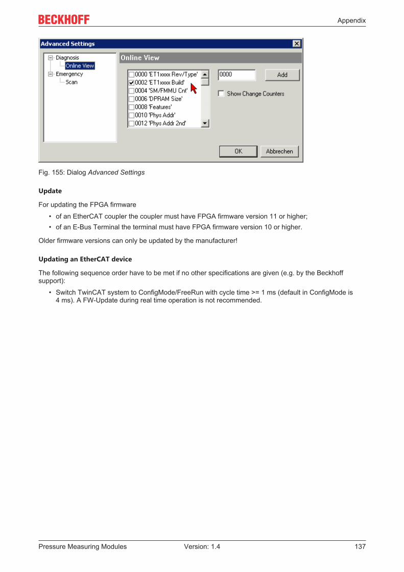
Appendix
Pressure Measuring Modules 137Version: 1.4
Fig. 155: Dialog Advanced Settings
Update
For updating the FPGA firmware
• of an EtherCAT coupler the coupler must have FPGA firmware version 11 or higher;• of an E-Bus Terminal the terminal must have FPGA firmware version 10 or higher.
Older firmware versions can only be updated by the manufacturer!
Updating an EtherCAT device
The following sequence order have to be met if no other specifications are given (e.g. by the Beckhoffsupport):
• Switch TwinCAT system to ConfigMode/FreeRun with cycle time >= 1 ms (default in ConfigMode is4 ms). A FW-Update during real time operation is not recommended.

Appendix
Pressure Measuring Modules138 Version: 1.4
• In the TwinCAT System Manager select the terminal for which the FPGA firmware is to be updated (inthe example: Terminal 5: EL5001) and click the Advanced Settings button in the EtherCAT tab:
• The Advanced Settings dialog appears. Under ESC Access/E²PROM/FPGA click on Write FPGAbutton:

Appendix
Pressure Measuring Modules 139Version: 1.4
• Select the file (*.rbf) with the new FPGA firmware, and transfer it to the EtherCAT device:
• Wait until download ends• Switch slave current less for a short time (don't pull under voltage!). In order to activate the new FPGA
firmware a restart (switching the power supply off and on again) of the EtherCAT device is required.• Check the new FPGA status
NOTERisk of damage to the device!A download of firmware to an EtherCAT device must not be interrupted in any case! If you interrupt thisprocess by switching off power supply or disconnecting the Ethernet link, the EtherCAT device can only berecommissioned by the manufacturer!
7.3.5 Simultaneous updating of several EtherCAT devicesThe firmware and ESI descriptions of several devices can be updated simultaneously, provided the deviceshave the same firmware file/ESI.
Fig. 156: Multiple selection and firmware update
Select the required slaves and carry out the firmware update in BOOTSTRAP mode as described above.

Appendix
Pressure Measuring Modules140 Version: 1.4
7.4 Restoring the delivery stateTo restore the delivery state (factory settings) for backup objects in ELxxxx terminals, the CoE objectRestore default parameters, SubIndex 001 can be selected in the TwinCAT System Manager (Config mode)(see Fig. Selecting the Restore default parameters PDO)
Fig. 157: Selecting the Restore default parameters PDO
Double-click on SubIndex 001 to enter the Set Value dialog. Enter the value 1684107116 in field Dec or thevalue 0x64616F6C in field Hex and confirm with OK (Fig. Entering a restore value in the Set Value dialog).All backup objects are reset to the delivery state.
Fig. 158: Entering a restore value in the Set Value dialog
Alternative restore valueIn some older terminals the backup objects can be switched with an alternative restore value: Deci-mal value: 1819238756, Hexadecimal value: 0x6C6F6164An incorrect entry for the restore valuehas no effect.

Appendix
Pressure Measuring Modules 141Version: 1.4
7.5 Support and ServiceBeckhoff and their partners around the world offer comprehensive support and service, making available fastand competent assistance with all questions related to Beckhoff products and system solutions.
Beckhoff's branch offices and representatives
Please contact your Beckhoff branch office or representative for local support and service on Beckhoffproducts!
The addresses of Beckhoff's branch offices and representatives round the world can be found on her internetpages: https://www.beckhoff.com
You will also find further documentation for Beckhoff components there.
Beckhoff Support
Support offers you comprehensive technical assistance, helping you not only with the application ofindividual Beckhoff products, but also with other, wide-ranging services:
• support• design, programming and commissioning of complex automation systems• and extensive training program for Beckhoff system components
Hotline: +49 5246 963 157Fax: +49 5246 963 9157e-mail: [email protected]
Beckhoff Service
The Beckhoff Service Center supports you in all matters of after-sales service:
• on-site service• repair service• spare parts service• hotline service
Hotline: +49 5246 963 460Fax: +49 5246 963 479e-mail: [email protected]
Beckhoff Headquarters
Beckhoff Automation GmbH & Co. KG
Huelshorstweg 2033415 VerlGermany
Phone: +49 5246 963 0Fax: +49 5246 963 198e-mail: [email protected]: https://www.beckhoff.com


Beckhoff Automation GmbH & Co. KGHülshorstweg 2033415 VerlGermanyPhone: +49 5246 [email protected]
More Information: www.beckhoff.com/EM3701