documentation | en - el3255 - download - beckhoff
TRANSCRIPT

Documentation | EN
EL32555 Channel Potentiometer Measurement with Sensor Supply
2022-01-13 | Version: 3.1


Table of contents
EL3255 3Version: 3.1
Table of contents1 Foreword .................................................................................................................................................... 5
1.1 Notes on the documentation.............................................................................................................. 51.2 Safety instructions ............................................................................................................................. 61.3 Documentation issue status .............................................................................................................. 71.4 Version identification of EtherCAT devices ....................................................................................... 9
1.4.1 General notes on marking ................................................................................................. 91.4.2 Version identification of EL terminals............................................................................... 101.4.3 Beckhoff Identification Code (BIC)................................................................................... 111.4.4 Electronic access to the BIC (eBIC) ................................................................................ 13
2 Product description................................................................................................................................. 152.1 Introduction...................................................................................................................................... 152.2 Technical data ................................................................................................................................. 162.3 Start ................................................................................................................................................. 17
3 Basics communication ........................................................................................................................... 183.1 EtherCAT basics.............................................................................................................................. 183.2 EtherCAT cabling – wire-bound....................................................................................................... 183.3 General notes for setting the watchdog........................................................................................... 193.4 EtherCAT State Machine................................................................................................................. 213.5 CoE Interface................................................................................................................................... 223.6 Distributed Clock ............................................................................................................................. 27
4 Mounting and wiring................................................................................................................................ 284.1 Instructions for ESD protection........................................................................................................ 284.2 Explosion protection ........................................................................................................................ 29
4.2.1 ATEX - Special conditions (extended temperature range) .............................................. 294.2.2 Continuative documentation for ATEX and IECEx .......................................................... 30
4.3 UL notice ......................................................................................................................................... 314.4 Installation on mounting rails ........................................................................................................... 324.5 Installation instructions for enhanced mechanical load capacity ..................................................... 354.6 Connection ...................................................................................................................................... 36
4.6.1 Connection system .......................................................................................................... 364.6.2 Wiring............................................................................................................................... 384.6.3 Shielding .......................................................................................................................... 39
4.7 Positioning of passive Terminals ..................................................................................................... 404.8 Installation positions ........................................................................................................................ 414.9 Diagnosis LEDs ............................................................................................................................... 434.10 Connection ...................................................................................................................................... 444.11 Disposal ........................................................................................................................................... 45
5 Commissioning........................................................................................................................................ 465.1 Quick start........................................................................................................................................ 465.2 TwinCAT Quick Start ....................................................................................................................... 51
5.2.1 TwinCAT 2 ....................................................................................................................... 535.2.2 TwinCAT 3 ....................................................................................................................... 63
5.3 TwinCAT Development Environment .............................................................................................. 77

Table of contents
EL32554 Version: 3.1
5.3.1 Installation of the TwinCAT real-time driver..................................................................... 775.3.2 Notes regarding ESI device description........................................................................... 835.3.3 TwinCAT ESI Updater ..................................................................................................... 875.3.4 Distinction between Online and Offline............................................................................ 875.3.5 OFFLINE configuration creation ...................................................................................... 885.3.6 ONLINE configuration creation ........................................................................................ 935.3.7 EtherCAT subscriber configuration................................................................................ 1015.3.8 Import/Export of EtherCAT devices with SCI and XTI ................................................... 110
5.4 General Notes - EtherCAT Slave Application................................................................................ 1175.5 Basics about signal isolators, barriers ........................................................................................... 1255.6 Notices on analog specifications ................................................................................................... 127
5.6.1 Full scale value (FSV).................................................................................................... 1275.6.2 Measuring error/ measurement deviation ...................................................................... 1275.6.3 Temperature coefficient tK [ppm/K] ............................................................................... 1285.6.4 Long-term use................................................................................................................ 1295.6.5 Ground reference: single-ended/differential typification ................................................ 1295.6.6 Common-mode voltage and reference ground (based on differential inputs)................ 1345.6.7 Dielectric strength .......................................................................................................... 1355.6.8 Temporal aspects of analog/digital conversion.............................................................. 1365.6.9 Explanation of the term GND/Ground............................................................................ 1395.6.10 Sampling type: Simultaneous vs. multiplexed ............................................................... 141
5.7 Process data and operating modes............................................................................................... 1445.7.1 Basic function principles ................................................................................................ 1445.7.2 Application notes ........................................................................................................... 1505.7.3 Process data.................................................................................................................. 1525.7.4 Object description and parameterization ....................................................................... 157
6 Appendix ................................................................................................................................................ 1686.1 EtherCAT AL Status Codes........................................................................................................... 1686.2 Firmware Update EL/ES/EM/ELM/EPxxxx .................................................................................... 169
6.2.1 Device description ESI file/XML..................................................................................... 1706.2.2 Firmware explanation .................................................................................................... 1736.2.3 Updating controller firmware *.efw................................................................................. 1736.2.4 FPGA firmware *.rbf....................................................................................................... 1756.2.5 Simultaneous updating of several EtherCAT devices.................................................... 179
6.3 Firmware compatibility ................................................................................................................... 1806.4 Restoring the delivery state ........................................................................................................... 1816.5 Support and Service ...................................................................................................................... 182

Foreword
EL3255 5Version: 3.1
1 Foreword
1.1 Notes on the documentation
Intended audience
This description is only intended for the use of trained specialists in control and automation engineering whoare familiar with the applicable national standards.It is essential that the documentation and the following notes and explanations are followed when installingand commissioning these components.It is the duty of the technical personnel to use the documentation published at the respective time of eachinstallation and commissioning.
The responsible staff must ensure that the application or use of the products described satisfy all therequirements for safety, including all the relevant laws, regulations, guidelines and standards.
Disclaimer
The documentation has been prepared with care. The products described are, however, constantly underdevelopment.
We reserve the right to revise and change the documentation at any time and without prior announcement.
No claims for the modification of products that have already been supplied may be made on the basis of thedata, diagrams and descriptions in this documentation.
Trademarks
Beckhoff®, TwinCAT®, TwinCAT/BSD®, TC/BSD®, EtherCAT®, EtherCAT G®, EtherCAT G10®, EtherCAT P®,Safety over EtherCAT®, TwinSAFE®, XFC®, XTS® and XPlanar® are registered trademarks of and licensed byBeckhoff Automation GmbH. Other designations used in this publication may be trademarks whose use bythird parties for their own purposes could violate the rights of the owners.
Patent Pending
The EtherCAT Technology is covered, including but not limited to the following patent applications andpatents: EP1590927, EP1789857, EP1456722, EP2137893, DE102015105702 with correspondingapplications or registrations in various other countries.
EtherCAT® is registered trademark and patented technology, licensed by Beckhoff Automation GmbH,Germany.
Copyright
© Beckhoff Automation GmbH & Co. KG, Germany.The reproduction, distribution and utilization of this document as well as the communication of its contents toothers without express authorization are prohibited.Offenders will be held liable for the payment of damages. All rights reserved in the event of the grant of apatent, utility model or design.

Foreword
EL32556 Version: 3.1
1.2 Safety instructions
Safety regulations
Please note the following safety instructions and explanations!Product-specific safety instructions can be found on following pages or in the areas mounting, wiring,commissioning etc.
Exclusion of liability
All the components are supplied in particular hardware and software configurations appropriate for theapplication. Modifications to hardware or software configurations other than those described in thedocumentation are not permitted, and nullify the liability of Beckhoff Automation GmbH & Co. KG.
Personnel qualification
This description is only intended for trained specialists in control, automation and drive engineering who arefamiliar with the applicable national standards.
Description of instructions
In this documentation the following instructions are used. These instructions must be read carefully and followed without fail!
DANGERSerious risk of injury!Failure to follow this safety instruction directly endangers the life and health of persons.
WARNINGRisk of injury!Failure to follow this safety instruction endangers the life and health of persons.
CAUTIONPersonal injuries!Failure to follow this safety instruction can lead to injuries to persons.
NOTEDamage to environment/equipment or data lossFailure to follow this instruction can lead to environmental damage, equipment damage or data loss.
Tip or pointerThis symbol indicates information that contributes to better understanding.

Foreword
EL3255 7Version: 3.1
1.3 Documentation issue statusVersion Comment3.1 • Update chapter “Technical data”
• Update structure3.0 • Update chapter “Technical data”
• Chapter "Commissioning": addenda subchapter "Basics about signal isolators, barriers"• Update chapter “Version identification of EtherCAT devices”• Update structure• Update Notes• Update revision status• Chapter Disposal added
2.9 • Update chapter "Technical data"• Update structure
2.8 • Update chapter “UL notice”• Update chapter “Firmware compatibility”• Update structure
2.7 • Update chapter "LEDs and connection"• Update structure• Update revision version
2.6 • Update chapter "Application notes"• Update chapter "Object description and parameterizatoin"• Update structure• Update revision version
2.5 • Update chapter "LEDs and connection"• Update structure• Update revision version
2.4 • Update chapter "Technical data"• Addenda chapter "Instructions for ESD protection"• Chapter “Analog technical notices - specifications” replaced by chapter “Notices on analog
specifications”2.3 • Update chapter "Notes on the documentation"
• Correction of Technical data• Update chapter "TwinCAT 2.1x" -> "TwinCAT Development Environment" and "TwinCAT
Quick Start"• Correction revision status
2.2 • Update chapter “Analog technical notices - specifications”2.1 • Update chapter “Process data calculation”

Foreword
EL32558 Version: 3.1
Version Comment2.0 • Migration to ST4
• Update structure• Update revision version
1.6 • Update chapter "Technical data"• Addenda chapter "Installation instructions for enhanced mechanical load capacity"• Update structure• Update revision version
1.5 • Update chapter "Basic function principles"• Update revision status
1.4 • Update Technical data• Update revision status
1.3 • Update revision status1.2 • Addenda open-circuit recognition1.1 • Update Technical data
• Addenda open-circuit recognition1.0 • Addenda and 1st public issue0.2 • Addenda0.1 • Provisional documentation for EL3255

Foreword
EL3255 9Version: 3.1
1.4 Version identification of EtherCAT devices
1.4.1 General notes on marking
Designation
A Beckhoff EtherCAT device has a 14-digit designation, made up of
• family key• type• version• revision
Example Family Type Version RevisionEL3314-0000-0016 EL terminal
(12 mm, non-pluggable connectionlevel)
3314 (4-channel thermocoupleterminal)
0000 (basic type) 0016
ES3602-0010-0017 ES terminal(12 mm, pluggableconnection level)
3602 (2-channel voltagemeasurement)
0010 (high-precision version)
0017
CU2008-0000-0000 CU device 2008 (8-port fast ethernet switch) 0000 (basic type) 0000
Notes• The elements mentioned above result in the technical designation. EL3314-0000-0016 is used in the
example below.• EL3314-0000 is the order identifier, in the case of “-0000” usually abbreviated to EL3314. “-0016” is the
EtherCAT revision.• The order identifier is made up of
- family key (EL, EP, CU, ES, KL, CX, etc.)- type (3314)- version (-0000)
• The revision -0016 shows the technical progress, such as the extension of features with regard to theEtherCAT communication, and is managed by Beckhoff.In principle, a device with a higher revision can replace a device with a lower revision, unless specifiedotherwise, e.g. in the documentation.Associated and synonymous with each revision there is usually a description (ESI, EtherCAT SlaveInformation) in the form of an XML file, which is available for download from the Beckhoff web site. From 2014/01 the revision is shown on the outside of the IP20 terminals, see Fig. “EL5021 EL terminal,standard IP20 IO device with batch number and revision ID (since 2014/01)”.
• The type, version and revision are read as decimal numbers, even if they are technically saved inhexadecimal.

Foreword
EL325510 Version: 3.1
1.4.2 Version identification of EL terminalsThe serial number/ data code for Beckhoff IO devices is usually the 8-digit number printed on the device oron a sticker. The serial number indicates the configuration in delivery state and therefore refers to a wholeproduction batch, without distinguishing the individual modules of a batch.
Structure of the serial number: KK YY FF HHKK - week of production (CW, calendar week)YY - year of productionFF - firmware versionHH - hardware version
Example with serial number 12 06 3A 02:12 - production week 1206 - production year 20063A - firmware version 3A02 - hardware version 02
Fig. 1: EL2872 with revision 0022 and serial number 01200815

Foreword
EL3255 11Version: 3.1
1.4.3 Beckhoff Identification Code (BIC)The Beckhoff Identification Code (BIC) is increasingly being applied to Beckhoff products to uniquely identifythe product. The BIC is represented as a Data Matrix Code (DMC, code scheme ECC200), the content isbased on the ANSI standard MH10.8.2-2016.
Fig. 2: BIC as data matrix code (DMC, code scheme ECC200)
The BIC will be introduced step by step across all product groups.
Depending on the product, it can be found in the following places:
• on the packaging unit• directly on the product (if space suffices)• on the packaging unit and the product
The BIC is machine-readable and contains information that can also be used by the customer for handlingand product management.
Each piece of information can be uniquely identified using the so-called data identifier(ANSI MH10.8.2-2016). The data identifier is followed by a character string. Both together have a maximumlength according to the table below. If the information is shorter, spaces are added to it.
Following information is possible, positions 1 to 4 are always present, the other according to need ofproduction:

Foreword
EL325512 Version: 3.1
Posi-tion
Type ofinformation
Explanation Dataidentifier
Number of digitsincl. data identifier
Example
1 Beckhoff ordernumber
Beckhoff order number 1P 8 1P072222
2 Beckhoff TraceabilityNumber (BTN)
Unique serial number,see note below
SBTN 12 SBTNk4p562d7
3 Article description Beckhoff articledescription, e.g.EL1008
1K 32 1KEL1809
4 Quantity Quantity in packagingunit, e.g. 1, 10, etc.
Q 6 Q1
5 Batch number Optional: Year and weekof production
2P 14 2P401503180016
6 ID/serial number Optional: Present-dayserial number system,e.g. with safety products
51S 12 51S678294
7 Variant number Optional: Product variantnumber on the basis ofstandard products
30P 32 30PF971, 2*K183
...
Further types of information and data identifiers are used by Beckhoff and serve internal processes.
Structure of the BIC
Example of composite information from positions 1 to 4 and with the above given example value on position6. The data identifiers are highlighted in bold font:
1P072222SBTNk4p562d71KEL1809 Q1 51S678294
Accordingly as DMC:
Fig. 3: Example DMC 1P072222SBTNk4p562d71KEL1809 Q1 51S678294
BTN
An important component of the BIC is the Beckhoff Traceability Number (BTN, position 2). The BTN is aunique serial number consisting of eight characters that will replace all other serial number systems atBeckhoff in the long term (e.g. batch designations on IO components, previous serial number range forsafety products, etc.). The BTN will also be introduced step by step, so it may happen that the BTN is not yetcoded in the BIC.
NOTEThis information has been carefully prepared. However, the procedure described is constantly being furtherdeveloped. We reserve the right to revise and change procedures and documentation at any time and with-out prior notice. No claims for changes can be made from the information, illustrations and descriptions inthis information.

Foreword
EL3255 13Version: 3.1
1.4.4 Electronic access to the BIC (eBIC)
Electronic BIC (eBIC)
The Beckhoff Identification Code (BIC) is applied to the outside of Beckhoff products in a visible place. Ifpossible, it should also be electronically readable.
Decisive for the electronic readout is the interface via which the product can be electronically addressed.
K-bus devices (IP20, IP67)
Currently, no electronic storage and readout is planned for these devices.
EtherCAT devices (IP20, IP67)
All Beckhoff EtherCAT devices have a so-called ESI-EEPROM, which contains the EtherCAT identity withthe revision number. Stored in it is the EtherCAT slave information, also colloquially known as ESI/XMLconfiguration file for the EtherCAT master. See the corresponding chapter in the EtherCAT system manual(Link) for the relationships.
The eBIC is also stored in the ESI‑EEPROM. The eBIC was introduced into the Beckhoff I/O production(terminals, boxes) from 2020; widespread implementation is expected in 2021.
The user can electronically access the eBIC (if existent) as follows:
• With all EtherCAT devices, the EtherCAT master (TwinCAT) can read the eBIC from the ESI‑EEPROM◦ From TwinCAT 4024.11, the eBIC can be displayed in the online view.◦ To do this,
check the checkbox "Show Beckhoff Identification Code (BIC)" underEtherCAT → Advanced Settings → Diagnostics:
◦ The BTN and its contents are then displayed:
◦ Note: as can be seen in the illustration, the production data HW version, FW version andproduction date, which have been programmed since 2012, can also be displayed with "ShowProduction Info".
• In the case of EtherCAT devices with CoE directory, the object 0x10E2:01 can additionally by used todisplay the device's own eBIC; the PLC can also simply access the information here:

Foreword
EL325514 Version: 3.1
◦ The device must be in SAFEOP/OP for access:
◦ the object 0x10E2 will be introduced into stock products in the course of a necessary firmwarerevision.
• Note: in the case of electronic further processing, the BTN is to be handled as a string(8); the identifier"SBTN" is not part of the BTN.
• Technical backgroundThe new BIC information is additionally written as a category in the ESI‑EEPROM during the deviceproduction. The structure of the ESI content is largely dictated by the ETG specifications, therefore theadditional vendor-specific content is stored with the help of a category according to ETG.2010. ID 03indicates to all EtherCAT masters that they must not overwrite these data in case of an update orrestore the data after an ESI update. The structure follows the content of the BIC, see there. This results in a memory requirement ofapprox. 50..200 bytes in the EEPROM.
• Special cases◦ If multiple, hierarchically arranged ESCs are installed in a device, only the top-level ESC carries
the eBIC Information.◦ If multiple, non-hierarchically arranged ESCs are installed in a device, all ESCs carry the eBIC
Information.◦ If the device consists of several sub-devices with their own identity, but only the top-level device is
accessible via EtherCAT, the eBIC of the top-level device is located in the CoE object directory0x10E2:01 and the eBICs of the sub-devices follow in 0x10E2:nn.
Profibus/Profinet/DeviceNet… Devices
Currently, no electronic storage and readout is planned for these devices.

Product description
EL3255 15Version: 3.1
2 Product description
2.1 Introduction
Fig. 4: EL3255
HD EtherCAT Terminal, 5-channel input, potentiometer analysis with sensor supply
The EL3255 EtherCAT Terminal enables potentiometers to be connected directly. A stabilized power supplyin the terminal for the connected potentiometers and ratiometric measurement of the input voltage offer theprerequisites for precise measuring. On account of its high sampling rate and together with potentiometerposition encoders, the compact, 5-channel EtherCAT terminal represents an economical position detector.
The EL3255 diagnostics detect broken wire, loss of supply voltage and short-circuit for each channel.
The 5 channels are measured simultaneously (at the same time).
The HD EtherCAT Terminals (High Density) with increased packing density are equipped with 16 connectionpoints in the housing of a 12-mm terminal block.
Quick links
• EtherCAT basics [} 18]• QuickStart [} 46]• Creation of the configuration [} 77]• Process data [} 152]• CoE object description [} 157]

Product description
EL325516 Version: 3.1
2.2 Technical dataTechnical data EL3255Number of inputs 5Power supply via power contactsTechnology Ratiometric potentiometer evaluation with own supply, 3-wire connectionDistributed Clocks yesFeed voltage potentiometer typ. 10 V ±10%Internal resistance >> 100 kΩ to wiper connectionSensor types Potentiometer 300 Ω…50 kΩOutput current max. 0.3 A total supply current for the potentiometerInput filter limit frequency typ. - 3 dB at 3 kHz and potentiometer 50 kOhmWiring fail indication yesConversion time typ. 300..700 µs, depending on settings
Default: approx. 500 µs (5 channels, filter deactivated)Resolution 16 bits (including sign)Sampling type simultaneousGround reference differentialMeasuring error < ±0.5 % (relative to full scale value)Voltage supply for electronic via the E-busSpecial features open-circuit recognition, supply monitoring, activatable filters, simultaneous measure-
ment of channelsElectrical isolation 500 V (E-bus/field voltage)Current consumption of power contacts (supplycontacts)
depends on potentiometers, max. 70 mA
Current consumption via E-bus typ. 80 mABit width in the process data image 5 x 16 bit inputConfiguration no address setting, configuration via the controllerConductor connection solid wire conductors: direct plug-in technique;
stranded wire conductors and ferrules: spring actuation by screwdriverRated cross-section solid wire: 0.08…1.5 mm²; stranded wire: 0.25...1.5 mm²; ferrule: 0.14…0.75 mm²Max. Sensor cable length The cable length from the EtherCAT Terminal to the sensor/encoder must not exceed
30 m without further protective measures. Suitable surge protection must be providedfor longer cable lengths
Weight approx. 70 gPermissible ambient temperature range duringoperation
-25°C ... +60°C (extended temperature range)
Permissible ambient temperature range duringstorage
-40°C ... +85°C
Permissible relative humidity 95%, no condensationDimensions (W x H x D) approx. 15 mm x 100 mm x 70 mmMounting [} 32] on 35 mm mounting rail conforms to EN 60715
Vibration/shock resistance conforms to EN 60068-2-6 / EN 60068-2-27,see also installation instructions [} 35] for enhanced mechanical load capacity
EMC immunity/emission conforms to EN 61000-6-2 / EN 61000-6-4Protection class IP20Installation position variableMarking / Approval*) CE, UKCA, EAC
ATEX [} 29]cULus [} 31]
*) Real applicable approvals/markings see type plate on the side (product marking).
Ex marking
Standard MarkingATEX II 3 G Ex nA IIC T4 Gc

Product description
EL3255 17Version: 3.1
2.3 StartFor commissioning:
• mount the EL3255 as explained in the chapter Mounting and wiring [} 28]
• configure the EL3255 in TwinCAT as explained in the chapter Commissioning [} 46].

Basics communication
EL325518 Version: 3.1
3 Basics communication
3.1 EtherCAT basicsPlease refer to the EtherCAT System Documentation for the EtherCAT fieldbus basics.
3.2 EtherCAT cabling – wire-boundThe cable length between two EtherCAT devices must not exceed 100 m. This results from the FastEthernettechnology, which, above all for reasons of signal attenuation over the length of the cable, allows a maximumlink length of 5 + 90 + 5 m if cables with appropriate properties are used. See also the Designrecommendations for the infrastructure for EtherCAT/Ethernet.
Cables and connectors
For connecting EtherCAT devices only Ethernet connections (cables + plugs) that meet the requirements ofat least category 5 (CAt5) according to EN 50173 or ISO/IEC 11801 should be used. EtherCAT uses 4 wiresfor signal transfer.
EtherCAT uses RJ45 plug connectors, for example. The pin assignment is compatible with the Ethernetstandard (ISO/IEC 8802-3).
Pin Color of conductor Signal Description1 yellow TD + Transmission Data +2 orange TD - Transmission Data -3 white RD + Receiver Data +6 blue RD - Receiver Data -
Due to automatic cable detection (auto-crossing) symmetric (1:1) or cross-over cables can be used betweenEtherCAT devices from Beckhoff.
Recommended cablesIt is recommended to use the appropriate Beckhoff components e.g.- cable sets ZK1090-9191-xxxx respectively- RJ45 connector, field assembly ZS1090-0005- EtherCAT cable, field assembly ZB9010, ZB9020
Suitable cables for the connection of EtherCAT devices can be found on the Beckhoff website!
E-Bus supply
A bus coupler can supply the EL terminals added to it with the E-bus system voltage of 5 V; a coupler isthereby loadable up to 2 A as a rule (see details in respective device documentation).Information on how much current each EL terminal requires from the E-bus supply is available online and inthe catalogue. If the added terminals require more current than the coupler can supply, then power feedterminals (e.g. EL9410) must be inserted at appropriate places in the terminal strand.
The pre-calculated theoretical maximum E-Bus current is displayed in the TwinCAT System Manager. Ashortfall is marked by a negative total amount and an exclamation mark; a power feed terminal is to beplaced before such a position.

Basics communication
EL3255 19Version: 3.1
Fig. 5: System manager current calculation
NOTEMalfunction possible!The same ground potential must be used for the E-Bus supply of all EtherCAT terminals in a terminal block!
3.3 General notes for setting the watchdogELxxxx terminals are equipped with a safety feature (watchdog) that switches off the outputs after aspecifiable time e.g. in the event of an interruption of the process data traffic, depending on the device andsettings, e.g. in OFF state.
The EtherCAT slave controller (ESC) features two watchdogs:
• SM watchdog (default: 100 ms)• PDI watchdog (default: 100 ms)
SM watchdog (SyncManager Watchdog)
The SyncManager watchdog is reset after each successful EtherCAT process data communication with theterminal. If no EtherCAT process data communication takes place with the terminal for longer than the setand activated SM watchdog time, e.g. in the event of a line interruption, the watchdog is triggered and theoutputs are set to FALSE. The OP state of the terminal is unaffected. The watchdog is only reset after asuccessful EtherCAT process data access. Set the monitoring time as described below.
The SyncManager watchdog monitors correct and timely process data communication with the ESC from theEtherCAT side.
PDI watchdog (Process Data Watchdog)
If no PDI communication with the EtherCAT slave controller (ESC) takes place for longer than the set andactivated PDI watchdog time, this watchdog is triggered.PDI (Process Data Interface) is the internal interface between the ESC and local processors in the EtherCATslave, for example. The PDI watchdog can be used to monitor this communication for failure.
The PDI watchdog monitors correct and timely process data communication with the ESC from theapplication side.
The settings of the SM- and PDI-watchdog must be done for each slave separately in the TwinCAT SystemManager.

Basics communication
EL325520 Version: 3.1
Fig. 6: EtherCAT tab -> Advanced Settings -> Behavior -> Watchdog
Notes:
• the multiplier is valid for both watchdogs.• each watchdog has its own timer setting, the outcome of this in summary with the multiplier is a
resulting time.• Important: the multiplier/timer setting is only loaded into the slave at the start up, if the checkbox is
activated.If the checkbox is not activated, nothing is downloaded and the ESC settings remain unchanged.
Multiplier
Both watchdogs receive their pulses from the local terminal cycle, divided by the watchdog multiplier:
1/25 MHz * (watchdog multiplier + 2) = 100 µs (for default setting of 2498 for the multiplier)
The standard setting of 1000 for the SM watchdog corresponds to a release time of 100 ms.
The value in multiplier + 2 corresponds to the number of basic 40 ns ticks representing a watchdog tick.The multiplier can be modified in order to adjust the watchdog time over a larger range.
Example “Set SM watchdog”
This checkbox enables manual setting of the watchdog times. If the outputs are set and the EtherCATcommunication is interrupted, the SM watchdog is triggered after the set time and the outputs are erased.This setting can be used for adapting a terminal to a slower EtherCAT master or long cycle times. Thedefault SM watchdog setting is 100 ms. The setting range is 0...65535. Together with a multiplier with arange of 1...65535 this covers a watchdog period between 0...~170 seconds.
Basics communication
EL3255 21Version: 3.1
Calculation
Multiplier = 2498 → watchdog base time = 1 / 25 MHz * (2498 + 2) = 0.0001 seconds = 100 µsSM watchdog = 10000 → 10000 * 100 µs = 1 second watchdog monitoring time
CAUTIONUndefined state possible!The function for switching off of the SM watchdog via SM watchdog = 0 is only implemented in terminalsfrom version -0016. In previous versions this operating mode should not be used.
CAUTIONDamage of devices and undefined state possible!If the SM watchdog is activated and a value of 0 is entered the watchdog switches off completely. This isthe deactivation of the watchdog! Set outputs are NOT set in a safe state, if the communication is inter-rupted.
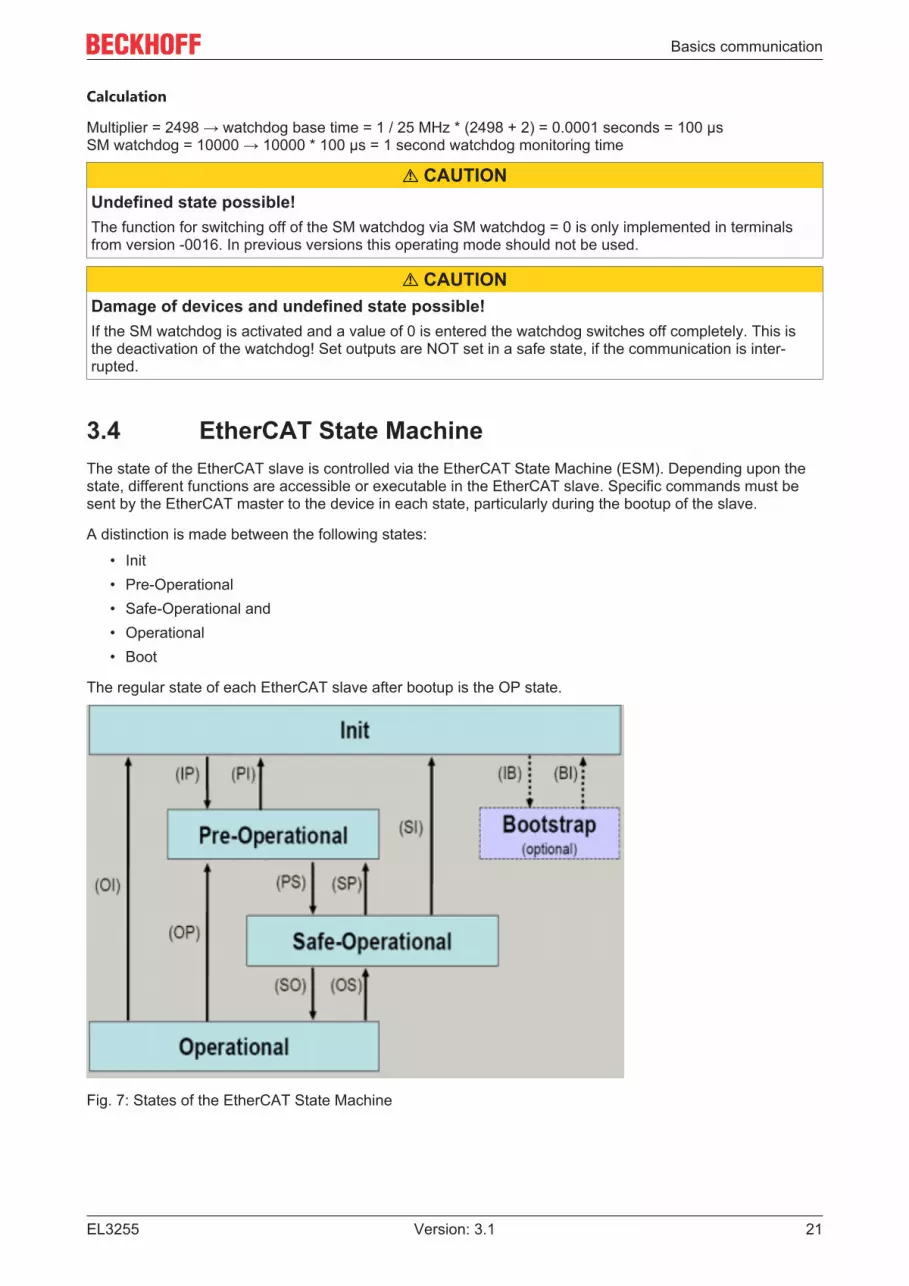
3.4 EtherCAT State MachineThe state of the EtherCAT slave is controlled via the EtherCAT State Machine (ESM). Depending upon thestate, different functions are accessible or executable in the EtherCAT slave. Specific commands must besent by the EtherCAT master to the device in each state, particularly during the bootup of the slave.
A distinction is made between the following states:
• Init• Pre-Operational• Safe-Operational and• Operational• Boot
The regular state of each EtherCAT slave after bootup is the OP state.
Fig. 7: States of the EtherCAT State Machine

Basics communication
EL325522 Version: 3.1
Init
After switch-on the EtherCAT slave in the Init state. No mailbox or process data communication is possible.The EtherCAT master initializes sync manager channels 0 and 1 for mailbox communication.
Pre-Operational (Pre-Op)
During the transition between Init and Pre-Op the EtherCAT slave checks whether the mailbox was initializedcorrectly.
In Pre-Op state mailbox communication is possible, but not process data communication. The EtherCATmaster initializes the sync manager channels for process data (from sync manager channel 2), the FMMUchannels and, if the slave supports configurable mapping, PDO mapping or the sync manager PDOassignment. In this state the settings for the process data transfer and perhaps terminal-specific parametersthat may differ from the default settings are also transferred.
Safe-Operational (Safe-Op)
During transition between Pre-Op and Safe-Op the EtherCAT slave checks whether the sync managerchannels for process data communication and, if required, the distributed clocks settings are correct. Beforeit acknowledges the change of state, the EtherCAT slave copies current input data into the associated DP-RAM areas of the EtherCAT slave controller (ECSC).
In Safe-Op state mailbox and process data communication is possible, although the slave keeps its outputsin a safe state, while the input data are updated cyclically.
Outputs in SAFEOP stateThe default set watchdog [} 19] monitoring sets the outputs of the module in a safe state - depend-ing on the settings in SAFEOP and OP - e.g. in OFF state. If this is prevented by deactivation of thewatchdog monitoring in the module, the outputs can be switched or set also in the SAFEOP state.
Operational (Op)
Before the EtherCAT master switches the EtherCAT slave from Safe-Op to Op it must transfer valid outputdata.
In the Op state the slave copies the output data of the masters to its outputs. Process data and mailboxcommunication is possible.
Boot
In the Boot state the slave firmware can be updated. The Boot state can only be reached via the Init state.
In the Boot state mailbox communication via the file access over EtherCAT (FoE) protocol is possible, but noother mailbox communication and no process data communication.
3.5 CoE Interface
General description
The CoE interface (CAN application protocol over EtherCAT)) is used for parameter management ofEtherCAT devices. EtherCAT slaves or the EtherCAT master manage fixed (read only) or variableparameters which they require for operation, diagnostics or commissioning.
CoE parameters are arranged in a table hierarchy. In principle, the user has read access via the fieldbus.The EtherCAT master (TwinCAT System Manager) can access the local CoE lists of the slaves viaEtherCAT in read or write mode, depending on the attributes.

Basics communication
EL3255 23Version: 3.1
Different CoE parameter types are possible, including string (text), integer numbers, Boolean values or largerbyte fields. They can be used to describe a wide range of features. Examples of such parameters includemanufacturer ID, serial number, process data settings, device name, calibration values for analogmeasurement or passwords.
The order is specified in two levels via hexadecimal numbering: (main)index, followed by subindex. Thevalue ranges are
• Index: 0x0000 …0xFFFF (0...65535dec)• SubIndex: 0x00…0xFF (0...255dec)
A parameter localized in this way is normally written as 0x8010:07, with preceding “0x” to identify thehexadecimal numerical range and a colon between index and subindex.
The relevant ranges for EtherCAT fieldbus users are:
• 0x1000: This is where fixed identity information for the device is stored, including name, manufacturer,serial number etc., plus information about the current and available process data configurations.
• 0x8000: This is where the operational and functional parameters for all channels are stored, such asfilter settings or output frequency.
Other important ranges are:
• 0x4000: here are the channel parameters for some EtherCAT devices. Historically, this was the firstparameter area before the 0x8000 area was introduced. EtherCAT devices that were previouslyequipped with parameters in 0x4000 and changed to 0x8000 support both ranges for compatibilityreasons and mirror internally.
• 0x6000: Input PDOs (“input” from the perspective of the EtherCAT master)• 0x7000: Output PDOs (“output” from the perspective of the EtherCAT master)
AvailabilityNot every EtherCAT device must have a CoE list. Simple I/O modules without dedicated processorusually have no variable parameters and therefore no CoE list.
If a device has a CoE list, it is shown in the TwinCAT System Manager as a separate tab with a listing of theelements:
Fig. 8: “CoE Online” tab

Basics communication
EL325524 Version: 3.1
The figure above shows the CoE objects available in device “EL2502”, ranging from 0x1000 to 0x1600. Thesubindices for 0x1018 are expanded.
Data management and function “NoCoeStorage”
Some parameters, particularly the setting parameters of the slave, are configurable and writeable. This canbe done in write or read mode
• via the System Manager (Fig. “CoE Online” tab) by clickingThis is useful for commissioning of the system/slaves. Click on the row of the index to beparameterized and enter a value in the “SetValue” dialog.
• from the control system/PLC via ADS, e.g. through blocks from the TcEtherCAT.lib libraryThis is recommended for modifications while the system is running or if no System Manager oroperating staff are available.
Data managementIf slave CoE parameters are modified online, Beckhoff devices store any changes in a fail-safemanner in the EEPROM, i.e. the modified CoE parameters are still available after a restart. The situation may be different with other manufacturers.
An EEPROM is subject to a limited lifetime with respect to write operations. From typically 100,000write operations onwards it can no longer be guaranteed that new (changed) data are reliably savedor are still readable. This is irrelevant for normal commissioning. However, if CoE parameters arecontinuously changed via ADS at machine runtime, it is quite possible for the lifetime limit to bereached. Support for the NoCoeStorage function, which suppresses the saving of changed CoE val-ues, depends on the firmware version.Please refer to the technical data in this documentation as to whether this applies to the respectivedevice.• If the function is supported: the function is activated by entering the code word 0x12345678 once
in CoE 0xF008 and remains active as long as the code word is not changed. After switching thedevice on it is then inactive. Changed CoE values are not saved in the EEPROM and can thusbe changed any number of times.
• Function is not supported: continuous changing of CoE values is not permissible in view of thelifetime limit.
Startup listChanges in the local CoE list of the terminal are lost if the terminal is replaced. If a terminal is re-placed with a new Beckhoff terminal, it will have the default settings. It is therefore advisable to linkall changes in the CoE list of an EtherCAT slave with the Startup list of the slave, which is pro-cessed whenever the EtherCAT fieldbus is started. In this way a replacement EtherCAT slave canautomatically be parameterized with the specifications of the user.If EtherCAT slaves are used which are unable to store local CoE values permanently, the Startuplist must be used.
Recommended approach for manual modification of CoE parameters• Make the required change in the System Manager
The values are stored locally in the EtherCAT slave• If the value is to be stored permanently, enter it in the Startup list.
The order of the Startup entries is usually irrelevant.

Basics communication
EL3255 25Version: 3.1
Fig. 9: Startup list in the TwinCAT System Manager
The Startup list may already contain values that were configured by the System Manager based on the ESIspecifications. Additional application-specific entries can be created.
Online/offline list
While working with the TwinCAT System Manager, a distinction has to be made whether the EtherCATdevice is “available”, i.e. switched on and linked via EtherCAT and therefore online, or whether aconfiguration is created offline without connected slaves.
In both cases a CoE list as shown in Fig. “CoE online tab” is displayed. The connectivity is shown as offline/online.
• If the slave is offline◦ The offline list from the ESI file is displayed. In this case modifications are not meaningful or
possible.◦ The configured status is shown under Identity.◦ No firmware or hardware version is displayed, since these are features of the physical device.◦ Offline is shown in red.
Fig. 10: Offline list

Basics communication
EL325526 Version: 3.1
• If the slave is online◦ The actual current slave list is read. This may take several seconds, depending on the size and
cycle time.◦ The actual identity is displayed◦ The firmware and hardware version of the equipment according to the electronic information is
displayed◦ Online is shown in green.
Fig. 11: Online list
Channel-based order
The CoE list is available in EtherCAT devices that usually feature several functionally equivalent channels.For example, a 4-channel analog 0...10 V input terminal also has four logical channels and therefore fouridentical sets of parameter data for the channels. In order to avoid having to list each channel in thedocumentation, the placeholder “n” tends to be used for the individual channel numbers.
In the CoE system 16 indices, each with 255 subindices, are generally sufficient for representing all channelparameters. The channel-based order is therefore arranged in 16dec/10hex steps. The parameter range0x8000 exemplifies this:
• Channel 0: parameter range 0x8000:00 ... 0x800F:255• Channel 1: parameter range 0x8010:00 ... 0x801F:255• Channel 2: parameter range 0x8020:00 ... 0x802F:255• ...
This is generally written as 0x80n0.
Detailed information on the CoE interface can be found in the EtherCAT system documentation on theBeckhoff website.

Basics communication
EL3255 27Version: 3.1
3.6 Distributed ClockThe distributed clock represents a local clock in the EtherCAT slave controller (ESC) with the followingcharacteristics:
• Unit 1 ns• Zero point 1.1.2000 00:00• Size 64 bit (sufficient for the next 584 years; however, some EtherCAT slaves only offer 32-bit support,
i.e. the variable overflows after approx. 4.2 seconds)• The EtherCAT master automatically synchronizes the local clock with the master clock in the EtherCAT
bus with a precision of < 100 ns.
For detailed information please refer to the EtherCAT system description.

Mounting and wiring
EL325528 Version: 3.1
4 Mounting and wiring
4.1 Instructions for ESD protectionNOTE
Destruction of the devices by electrostatic discharge possible!The devices contain components at risk from electrostatic discharge caused by improper handling.• Please ensure you are electrostatically discharged and avoid touching the contacts of the device directly.• Avoid contact with highly insulating materials (synthetic fibers, plastic film etc.).• Surroundings (working place, packaging and personnel) should by grounded probably, when handling
with the devices.
• Each assembly must be terminated at the right hand end with an EL9011 or EL9012 bus end cap, to en-sure the protection class and ESD protection.
Fig. 12: Spring contacts of the Beckhoff I/O components

Mounting and wiring
EL3255 29Version: 3.1
4.2 Explosion protection
4.2.1 ATEX - Special conditions (extended temperature range) WARNING
Observe the special conditions for the intended use of Beckhoff fieldbus components withextended temperature range (ET) in potentially explosive areas (directive 2014/34/EU)!• The certified components are to be installed in a suitable housing that guarantees a protection class of at
least IP54 in accordance with EN 60079-15! The environmental conditions during use are thereby to betaken into account!
• For dust (only the fieldbus components of certificate no. KEMA 10ATEX0075 X Issue 9): The equipmentshall be installed in a suitable enclosure providing a degree of protection of IP54 according toEN 60079-31 for group IIIA or IIIB and IP6X for group IIIC, taking into account the environmental condi-tions under which the equipment is used!
• If the temperatures during rated operation are higher than 70°C at the feed-in points of cables, lines orpipes, or higher than 80°C at the wire branching points, then cables must be selected whose tempera-ture data correspond to the actual measured temperature values!
• Observe the permissible ambient temperature range of -25 to 60°C for the use of Beckhoff fieldbus com-ponents with extended temperature range (ET) in potentially explosive areas!
• Measures must be taken to protect against the rated operating voltage being exceeded by more than40% due to short-term interference voltages!
• The individual terminals may only be unplugged or removed from the Bus Terminal system if the supplyvoltage has been switched off or if a non-explosive atmosphere is ensured!
• The connections of the certified components may only be connected or disconnected if the supply volt-age has been switched off or if a non-explosive atmosphere is ensured!
• The fuses of the KL92xx/EL92xx power feed terminals may only be exchanged if the supply voltage hasbeen switched off or if a non-explosive atmosphere is ensured!
• Address selectors and ID switches may only be adjusted if the supply voltage has been switched off or ifa non-explosive atmosphere is ensured!
Standards
The fundamental health and safety requirements are fulfilled by compliance with the following standards:
• EN 60079-0:2012+A11:2013• EN 60079-15:2010• EN 60079-31:2013 (only for certificate no. KEMA 10ATEX0075 X Issue 9)
Marking
The Beckhoff fieldbus components with extended temperature range (ET) certified according to the ATEXdirective for potentially explosive areas bear the following marking:
II 3G KEMA 10ATEX0075 X Ex nA IIC T4 Gc Ta: -25 … +60°CII 3D KEMA 10ATEX0075 X Ex tc IIIC T135°C Dc Ta: -25 ... +60°C (only for fieldbus components of certificate no. KEMA 10ATEX0075 X Issue 9)
or
II 3G KEMA 10ATEX0075 X Ex nA nC IIC T4 Gc Ta: -25 … +60°CII 3D KEMA 10ATEX0075 X Ex tc IIIC T135°C Dc Ta: -25 ... +60°C (only for fieldbus components of certificate no. KEMA 10ATEX0075 X Issue 9)

Mounting and wiring
EL325530 Version: 3.1
4.2.2 Continuative documentation for ATEX and IECExContinuative documentation about explosion protection according to ATEX andIECExPay also attention to the continuative documentationEx. Protection for Terminal SystemsNotes on the use of the Beckhoff terminal systems in hazardous areas according to ATEX andIECEx,
that is available for download within the download area of your product on the Beckhoff homepagewww.beckhoff.com!

Mounting and wiring
EL3255 31Version: 3.1
4.3 UL noticeApplicationBeckhoff EtherCAT modules are intended for use with Beckhoff’s UL Listed EtherCAT Sys-tem only.
ExaminationFor cULus examination, the Beckhoff I/O System has only been investigated for risk of fireand electrical shock (in accordance with UL508 and CSA C22.2 No. 142).
For devices with Ethernet connectorsNot for connection to telecommunication circuits.
Basic principles
UL certification according to UL508. Devices with this kind of certification are marked by this sign:

Mounting and wiring
EL325532 Version: 3.1
4.4 Installation on mounting rails WARNING
Risk of electric shock and damage of device!Bring the bus terminal system into a safe, powered down state before starting installation, disassembly orwiring of the bus terminals!
Assembly
Fig. 13: Attaching on mounting rail
The bus coupler and bus terminals are attached to commercially available 35 mm mounting rails (DIN railsaccording to EN 60715) by applying slight pressure:
1. First attach the fieldbus coupler to the mounting rail.2. The bus terminals are now attached on the right-hand side of the fieldbus coupler. Join the compo-
nents with tongue and groove and push the terminals against the mounting rail, until the lock clicksonto the mounting rail.If the terminals are clipped onto the mounting rail first and then pushed together without tongue andgroove, the connection will not be operational! When correctly assembled, no significant gap shouldbe visible between the housings.
Fixing of mounting railsThe locking mechanism of the terminals and couplers extends to the profile of the mounting rail. Atthe installation, the locking mechanism of the components must not come into conflict with the fixingbolts of the mounting rail. To mount the mounting rails with a height of 7.5 mm under the terminalsand couplers, you should use flat mounting connections (e.g. countersunk screws or blind rivets).

Mounting and wiring
EL3255 33Version: 3.1
Disassembly
Fig. 14: Disassembling of terminal
Each terminal is secured by a lock on the mounting rail, which must be released for disassembly:
1. Pull the terminal by its orange-colored lugs approximately 1 cm away from the mounting rail. In doingso for this terminal the mounting rail lock is released automatically and you can pull the terminal out ofthe bus terminal block easily without excessive force.
2. Grasp the released terminal with thumb and index finger simultaneous at the upper and lower groovedhousing surfaces and pull the terminal out of the bus terminal block.
Connections within a bus terminal block
The electric connections between the Bus Coupler and the Bus Terminals are automatically realized byjoining the components:
• The six spring contacts of the K-Bus/E-Bus deal with the transfer of the data and the supply of the BusTerminal electronics.
• The power contacts deal with the supply for the field electronics and thus represent a supply rail withinthe bus terminal block. The power contacts are supplied via terminals on the Bus Coupler (up to 24 V)or for higher voltages via power feed terminals.
Power ContactsDuring the design of a bus terminal block, the pin assignment of the individual Bus Terminals mustbe taken account of, since some types (e.g. analog Bus Terminals or digital 4-channel Bus Termi-nals) do not or not fully loop through the power contacts. Power Feed Terminals (KL91xx, KL92xxor EL91xx, EL92xx) interrupt the power contacts and thus represent the start of a new supply rail.
PE power contact
The power contact labeled PE can be used as a protective earth. For safety reasons this contact mates firstwhen plugging together, and can ground short-circuit currents of up to 125 A.

Mounting and wiring
EL325534 Version: 3.1
Fig. 15: Power contact on left side
NOTEPossible damage of the deviceNote that, for reasons of electromagnetic compatibility, the PE contacts are capacitatively coupled to themounting rail. This may lead to incorrect results during insulation testing or to damage on the terminal (e.g.disruptive discharge to the PE line during insulation testing of a consumer with a nominal voltage of 230 V).For insulation testing, disconnect the PE supply line at the Bus Coupler or the Power Feed Terminal! In or-der to decouple further feed points for testing, these Power Feed Terminals can be released and pulled atleast 10 mm from the group of terminals.
WARNINGRisk of electric shock!The PE power contact must not be used for other potentials!

Mounting and wiring
EL3255 35Version: 3.1
4.5 Installation instructions for enhanced mechanicalload capacity
WARNINGRisk of injury through electric shock and damage to the device!Bring the Bus Terminal system into a safe, de-energized state before starting mounting, disassembly orwiring of the Bus Terminals!
Additional checks
The terminals have undergone the following additional tests:
Verification ExplanationVibration 10 frequency runs in 3 axes
6 Hz < f < 60 Hz displacement 0.35 mm, constant amplitude60.1 Hz < f < 500 Hz acceleration 5 g, constant amplitude
Shocks 1000 shocks in each direction, in 3 axes25 g, 6 ms
Additional installation instructions
For terminals with enhanced mechanical load capacity, the following additional installation instructions apply:
• The enhanced mechanical load capacity is valid for all permissible installation positions• Use a mounting rail according to EN 60715 TH35-15• Fix the terminal segment on both sides of the mounting rail with a mechanical fixture, e.g. an earth
terminal or reinforced end clamp• The maximum total extension of the terminal segment (without coupler) is:
64 terminals (12 mm mounting with) or 32 terminals (24 mm mounting with)• Avoid deformation, twisting, crushing and bending of the mounting rail during edging and installation of
the rail• The mounting points of the mounting rail must be set at 5 cm intervals• Use countersunk head screws to fasten the mounting rail• The free length between the strain relief and the wire connection should be kept as short as possible. A
distance of approx. 10 cm should be maintained to the cable duct.

Mounting and wiring
EL325536 Version: 3.1
4.6 Connection
4.6.1 Connection system WARNING
Risk of electric shock and damage of device!Bring the bus terminal system into a safe, powered down state before starting installation, disassembly orwiring of the bus terminals!
Overview
The bus terminal system offers different connection options for optimum adaptation to the respectiveapplication:
• The terminals of ELxxxx and KLxxxx series with standard wiring include electronics and connectionlevel in a single enclosure.
• The terminals of ESxxxx and KSxxxx series feature a pluggable connection level and enable steadywiring while replacing.
• The High Density Terminals (HD Terminals) include electronics and connection level in a singleenclosure and have advanced packaging density.
Standard wiring (ELxxxx / KLxxxx)
Fig. 16: Standard wiring
The terminals of ELxxxx and KLxxxx series have been tried and tested for years.They feature integrated screwless spring force technology for fast and simple assembly.
Pluggable wiring (ESxxxx / KSxxxx)
Fig. 17: Pluggable wiring
The terminals of ESxxxx and KSxxxx series feature a pluggable connection level.The assembly and wiring procedure is the same as for the ELxxxx and KLxxxx series.The pluggable connection level enables the complete wiring to be removed as a plug connector from the topof the housing for servicing.The lower section can be removed from the terminal block by pulling the unlocking tab. Insert the new component and plug in the connector with the wiring. This reduces the installation time andeliminates the risk of wires being mixed up.
The familiar dimensions of the terminal only had to be changed slightly. The new connector adds about 3mm. The maximum height of the terminal remains unchanged.

Mounting and wiring
EL3255 37Version: 3.1
A tab for strain relief of the cable simplifies assembly in many applications and prevents tangling of individualconnection wires when the connector is removed.
Conductor cross sections between 0.08 mm2 and 2.5 mm2 can continue to be used with the proven springforce technology.
The overview and nomenclature of the product names for ESxxxx and KSxxxx series has been retained asknown from ELxxxx and KLxxxx series.
High Density Terminals (HD Terminals)
Fig. 18: High Density Terminals
The terminals from these series with 16 terminal points are distinguished by a particularly compact design,as the packaging density is twice as large as that of the standard 12 mm bus terminals. Massive conductorsand conductors with a wire end sleeve can be inserted directly into the spring loaded terminal point withouttools.
Wiring HD TerminalsThe High Density Terminals of the ELx8xx and KLx8xx series doesn't support pluggable wiring.
Ultrasonically “bonded” (ultrasonically welded) conductors
Ultrasonically “bonded” conductorsIt is also possible to connect the Standard and High Density Terminals with ultrasonically “bonded”(ultrasonically welded) conductors. In this case, please note the tables concerning the wire-sizewidth [} 38]!

Mounting and wiring
EL325538 Version: 3.1
4.6.2 Wiring WARNING
Risk of electric shock and damage of device!Bring the bus terminal system into a safe, powered down state before starting installation, disassembly orwiring of the bus terminals!
Terminals for standard wiring ELxxxx/KLxxxx and for pluggable wiring ESxxxx/KSxxxx
Fig. 19: Connecting a cable on a terminal point
Up to eight terminal points enable the connection of solid or finely stranded cables to the bus terminal. Theterminal points are implemented in spring force technology. Connect the cables as follows:
1. Open a terminal point by pushing a screwdriver straight against the stop into the square openingabove the terminal point. Do not turn the screwdriver or move it alternately (don't toggle).
2. The wire can now be inserted into the round terminal opening without any force.3. The terminal point closes automatically when the pressure is released, holding the wire securely and
permanently.
See the following table for the suitable wire size width.
Terminal housing ELxxxx, KLxxxx ESxxxx, KSxxxxWire size width (single core wires) 0.08 ... 2.5 mm2 0.08 ... 2.5 mm2
Wire size width (fine-wire conductors) 0.08 ... 2.5 mm2 0.08 ... 2.5 mm2
Wire size width (conductors with a wire end sleeve) 0.14 ... 1.5 mm2 0.14 ... 1.5 mm2
Wire stripping length 8 ... 9 mm 9 ... 10 mm
High Density Terminals (HD Terminals [} 37]) with 16 terminal points
The conductors of the HD Terminals are connected without tools for single-wire conductors using the directplug-in technique, i.e. after stripping the wire is simply plugged into the terminal point. The cables arereleased, as usual, using the contact release with the aid of a screwdriver. See the following table for thesuitable wire size width.

Mounting and wiring
EL3255 39Version: 3.1
Terminal housing High Density HousingWire size width (single core wires) 0.08 ... 1.5 mm2
Wire size width (fine-wire conductors) 0.25 ... 1.5 mm2
Wire size width (conductors with a wire end sleeve) 0.14 ... 0.75 mm2
Wire size width (ultrasonically “bonded" conductors) only 1.5 mm2 (see notice [} 37])Wire stripping length 8 ... 9 mm
4.6.3 ShieldingShieldingEncoder, analog sensors and actors should always be connected with shielded, twisted pairedwires.

Mounting and wiring
EL325540 Version: 3.1
4.7 Positioning of passive TerminalsHint for positioning of passive terminals in the bus terminal blockEtherCAT Terminals (ELxxxx / ESxxxx), which do not take an active part in data transfer within thebus terminal block are so called passive terminals. The passive terminals have no current consump-tion out of the E-Bus. To ensure an optimal data transfer, you must not directly string together more than two passive ter-minals!
Examples for positioning of passive terminals (highlighted)
Fig. 20: Correct positioning
Fig. 21: Incorrect positioning

Mounting and wiring
EL3255 41Version: 3.1
4.8 Installation positionsNOTE
Constraints regarding installation position and operating temperature rangePlease refer to the technical data for a terminal to ascertain whether any restrictions regarding the installa-tion position and/or the operating temperature range have been specified. When installing high power dissi-pation terminals ensure that an adequate spacing is maintained between other components above and be-low the terminal in order to guarantee adequate ventilation!
Optimum installation position (standard)
The optimum installation position requires the mounting rail to be installed horizontally and the connectionsurfaces of the EL/KL terminals to face forward (see Fig. Recommended distances for standard installationposition). The terminals are ventilated from below, which enables optimum cooling of the electronics throughconvection. “From below” is relative to the acceleration of gravity.
Fig. 22: Recommended distances for standard installation position
Compliance with the distances shown in Fig. Recommended distances for standard installation position isrecommended.
Other installation positions
All other installation positions are characterized by different spatial arrangement of the mounting rail - seeFig Other installation positions.
The minimum distances to ambient specified above also apply to these installation positions.

Mounting and wiring
EL325542 Version: 3.1
Fig. 23: Other installation positions

Mounting and wiring
EL3255 43Version: 3.1
4.9 Diagnosis LEDs
Fig. 24: EL3255 - Diagnosis LEDs
LED Color MeaningRUN green This LED indicates the terminal's operating state:
off State of the EtherCAT State Machine: INIT = initialization of theterminal
flashing uniformly State of the EtherCAT State Machine [} 21]: PREOP = functionfor mailbox communication and different standard-settings set
flashing slowly State of the EtherCAT State Machine: SAFEOP = verification ofthe sync manager [} 101] channels and the distributed clocks.Outputs remain in safe state
on State of the EtherCAT State Machine: OP = normal operatingstate; mailbox-and process data communication is possible
flashing rapidly State of the EtherCAT State Machine: BOOTSTRAP = functionfor terminal firmware updates [} 169]
Sig ERR Chx
red There is an error on the corresponding channel:- broken wire on wiper or supply- potentiometer outside the specified range (300 - 50 kOhm)- short-circuit- overloadIf channels are not used they can be deactivated via the PDO selection. Thecorresponding LED then goes out.
Power fail red This LED lights up if the 24V supply via the power contacts is absent.

Mounting and wiring
EL325544 Version: 3.1
4.10 Connection
Fig. 25: EL3255
The 24V supply via the power contacts is required for the operation of the EL3255.
Terminal point DescriptionName No.0 V 1 Potentiometer 1, feed AInput 1 2 Potentiometer 1, tap0 V 3 Potentiometer 4, feed A0 V 4 Potentiometer 2, feed AInput 2 5 Potentiometer 2, tap0 V 6 Potentiometer 3, feed AInput 3 7 Potentiometer 3, tap0 V 8 Potentiometer 5, feed A+10 V 9 Potentiometer 1, feed BInput 4 10 Potentiometer 4, tap+10 V 11 Potentiometer 4, feed B+10 V 12 Potentiometer 2, feed B- 13+10 V 14 Potentiometer 3, feed BInput 5 15 Potentiometer 5, tap+10 V 16 Potentiometer 5, feed B

Mounting and wiring
EL3255 45Version: 3.1
4.11 DisposalProducts marked with a crossed-out wheeled bin shall not be discardedwith the normal waste stream. The device is considered as wasteelectrical and electronic equipment. The national regulations for thedisposal of waste electrical and electronic equipment must be observed.

Commissioning
EL325546 Version: 3.1
5 Commissioning
5.1 Quick startNo special measures are required for the initial commissioning of the EL3255.
1. Mounting
Install the EL3255 as described in section Mounting and wiring [} 28].
Connect 1 - 5 potentiometers according to the pin assignment.
2. Configuration
Create a configuration in the TwinCAT System Manager by manually inserting the terminal or scanning itonline. Refer to installation chapter TwinCAT 2.x [} 83] regarding this.
EtherCAT XML Device DescriptionIf the XML description of the EL3255 is not available in your system you can download the latestXML file from the download area of the Beckhoff website and install it according to the installationinstructions.
3. Online operation
Activate the EtherCAT master and start the terminal in OP state. In the input variables the EL3255 mustdeliver State=OP (8) and WC=0.
4. Delivery state
The terminal behaves as follows in the delivery state or after scanning in the System Manager:
• 5 channels active
• 10 kOhm potentiometer (CoE setting 0x80n0:1C) [} 158]• Distributed Clocks deactivated, frame-triggered operation• Filter deactivated• Vendor calibration active
This results in a conversion time of typically 500 µs across all channels.
• Process data status + value for each channel

Commissioning
EL3255 47Version: 3.1
Fig. 26: Default process data
Sensor position PDO-value0 % x0000 050 % x3FFF 16383100 % x7FFF 32767
• CoE settings (in this case channel 1: index x80n0, where n=0)
Fig. 27: default CoE parameters
5. Distributed Clocks mode
If you wish to use Distributed Clocks mode, change the process data and the mode of operation accordingly.
Since the EL3255 is a device for input data, "DC-Synchron (input based)" is recommended.
Fig. 28: Distributed Clocks operating mode
The scanning of the potentiometers is then cyclically initiated by the DC-Sync signal; hence, synchronizedoperation with other DC-capable terminals can take place.

Commissioning
EL325548 Version: 3.1
Distributed Clocks and filtersThe activation of the filters is not permissible in Distributed Clocks mode.
6. Setting the parameters and process data
Process data
Via the PDO selection, 5 - 1 channels can be selected as PDOs to be cyclically transmitted (A). Thedeactivation of a channel reduces the size of the process image; the corresponding Error LED then no longerhas any function.
Fig. 29: PDO selection
CoE parameters
The CoE parameters can now be changed for each channel in the CoE.
Parameterization via the CoE list (CAN over EtherCAT)The terminal is parameterized via the CoE - Online tab (double-click on the respective object) or viathe Process Data tab (allocation of PDOs). Please note the following general CoE information whenusing/manipulating the CoE parameters: - Keep a startup list if components have to be replaced -Differentiation between online/offline dictionary, existence of current XML description - Use "CoEreload" for resetting changes
The following settings should be made in each channel
1. Nominal resistance of connected potentiometer

Commissioning
EL3255 49Version: 3.1
The electrical measuring range encompasses potentiometers from 300 Ω to 50 kΩ. An internal correctionfunction improves the measuring accuracy by linearization if the connected potentiometer is known to theterminal.Therefore the load resistance is to be set in the CoE x80n0:1c. The setting closest to the actual value is tobe selected.
Fig. 30: CoE, nominal resistance setting
Note on open-circuit recognition from firmware 04 [} 180]• The open-circuit recognition runs acyclically in the background.• The open-circuit recognition for the potentiometer wiper takes place every 3 cycles, if the
value 10k (0) is entered in all 0x80n0:1C [} 158] objects (on all channels). In this case the open-circuit recognition is particularly fast. If a >20 kOhm potentiometer is nevertheless connected toone of the channels, a broken wire message may occur, even if no broken wire is present.Therefore, the nearest suitable value that matches the connected potentiometer should be set in0x80n0:1C [} 158].
• The open-circuit recognition for the wiper is slower, if at least for one channel a value >10k ( > 0)has been entered.
2. Filter setting
The filter setting from channel 1 is simultaneously effective for all channels.A combination of Distributed Clock mode and filter activation is not permissible.
Fig. 31: CoE, filter setting
With the exception of the filter setting, different values can be specified for each channel.
The settings can also be loaded via the SPS/PLC/Task at runtime, e.g. using function blocks fromTcEtherCAT.lib.

Commissioning
EL325550 Version: 3.1
7. Diagnostics
Both the terminal and each individual channel signal their proper function in status variables, see Processdata.
Fig. 32: Process data for the diagnosis
For proper operation the cyclic evaluation of the following information is recommended:
• Device EL3255◦ WorkingCounter WcState
must be 0 in each cycle, otherwise no valid data acceptance has taken place.◦ Status State
The EC status of the terminal must be in OP mode, i.e. the 3rd bit is set. There must not be anyerror.
• per channel◦ Error, Underrange, Overrange
These variables must be 0/FALSE.◦ SyncError
This variable indicates a synchronization error in DC mode and must be 0/FALSE.◦ TxPDO State
This variable indicates an internal process data error and must be 0/FALSE.◦ TxPDO Toggle
This variable indicates the delivery of new data by changing its value.
8. Operation
During operation the potentiometers/sensors are cyclically measured and the process value is transmitted tothe master.

Commissioning
EL3255 51Version: 3.1
5.2 TwinCAT Quick StartTwinCAT is a development environment for real-time control including multi-PLC system, NC axis control,programming and operation. The whole system is mapped through this environment and enables access to aprogramming environment (including compilation) for the controller. Individual digital or analog inputs oroutputs can also be read or written directly, in order to verify their functionality, for example.
For further information please refer to http://infosys.beckhoff.com:
• EtherCAT Systemmanual:Fieldbus Components → EtherCAT Terminals → EtherCAT System Documentation → Setup in theTwinCAT System Manager
• TwinCAT 2 → TwinCAT System Manager → I/O - Configuration• In particular, TwinCAT driver installation:
Fieldbus components → Fieldbus Cards and Switches → FC900x – PCI Cards for Ethernet →Installation
Devices contain the terminals for the actual configuration. All configuration data can be entered directly viaeditor functions (offline) or via the “Scan” function (online):
• “offline”: The configuration can be customized by adding and positioning individual components.These can be selected from a directory and configured.
◦ The procedure for offline mode can be found under http://infosys.beckhoff.com:TwinCAT 2 → TwinCAT System Manager → IO - Configuration → Adding an I/O Device
• “online”: The existing hardware configuration is read
◦ See also http://infosys.beckhoff.com:Fieldbus components → Fieldbus cards and switches → FC900x – PCI Cards for Ethernet →Installation → Searching for devices
The following relationship is envisaged from user PC to the individual control elements:
Fig. 33: Relationship between user side (commissioning) and installation

Commissioning
EL325552 Version: 3.1
The user inserting of certain components (I/O device, terminal, box...) is the same in TwinCAT 2 andTwinCAT 3. The descriptions below relate to the online procedure.
Sample configuration (actual configuration)
Based on the following sample configuration, the subsequent subsections describe the procedure forTwinCAT 2 and TwinCAT 3:
• Control system (PLC) CX2040 including CX2100-0004 power supply unit• Connected to the CX2040 on the right (E-bus):
EL1004 (4-channel digital input terminal 24 VDC)• Linked via the X001 port (RJ-45): EK1100 EtherCAT Coupler• Connected to the EK1100 EtherCAT coupler on the right (E-bus):
EL2008 (8-channel digital output terminal 24 VDC; 0.5 A)• (Optional via X000: a link to an external PC for the user interface)
Fig. 34: Control configuration with Embedded PC, input (EL1004) and output (EL2008)
Note that all combinations of a configuration are possible; for example, the EL1004 terminal could also beconnected after the coupler, or the EL2008 terminal could additionally be connected to the CX2040 on theright, in which case the EK1100 coupler wouldn’t be necessary.

Commissioning
EL3255 53Version: 3.1
5.2.1 TwinCAT 2
Startup
TwinCAT basically uses two user interfaces: the TwinCAT System Manager for communication with theelectromechanical components and TwinCAT PLC Control for the development and compilation of acontroller. The starting point is the TwinCAT System Manager.
After successful installation of the TwinCAT system on the PC to be used for development, the TwinCAT 2System Manager displays the following user interface after startup:
Fig. 35: Initial TwinCAT 2 user interface
Generally, TwinCAT can be used in local or remote mode. Once the TwinCAT system including the userinterface (standard) is installed on the respective PLC, TwinCAT can be used in local mode and thereby thenext step is “Insert Device [} 55]”.
If the intention is to address the TwinCAT runtime environment installed on a PLC as developmentenvironment remotely from another system, the target system must be made known first. In the menu under
“Actions” → “Choose Target System...”, via the symbol “ ” or the “F8” key, open the following window:

Commissioning
EL325554 Version: 3.1
Fig. 36: Selection of the target system
Use “Search (Ethernet)...” to enter the target system. Thus a next dialog opens to either:
• enter the known computer name after “Enter Host Name / IP:” (as shown in red)• perform a “Broadcast Search” (if the exact computer name is not known)• enter the known computer IP or AmsNetID.
Fig. 37: Specify the PLC for access by the TwinCAT System Manager: selection of the target system
Once the target system has been entered, it is available for selection as follows (a password may have to beentered):
After confirmation with “OK” the target system can be accessed via the System Manager.

Commissioning
EL3255 55Version: 3.1
Adding devices
In the configuration tree of the TwinCAT 2 System Manager user interface on the left, select “I/O Devices”and then right-click to open a context menu and select “Scan Devices…”, or start the action in the menu bar
via . The TwinCAT System Manager may first have to be set to “Config mode” via or via menu“Actions” → “Set/Reset TwinCAT to Config Mode…” (Shift + F4).
Fig. 38: Select “Scan Devices...”
Confirm the warning message, which follows, and select “EtherCAT” in the dialog:
Fig. 39: Automatic detection of I/O devices: selection the devices to be integrated
Confirm the message “Find new boxes”, in order to determine the terminals connected to the devices. “FreeRun” enables manipulation of input and output values in “Config mode” and should also be acknowledged.
Based on the sample configuration [} 52] described at the beginning of this section, the result is as follows:

Commissioning
EL325556 Version: 3.1
Fig. 40: Mapping of the configuration in the TwinCAT 2 System Manager
The whole process consists of two stages, which may be performed separately (first determine the devices,then determine the connected elements such as boxes, terminals, etc.). A scan can also be initiated byselecting “Device ...” from the context menu, which then reads the elements present in the configurationbelow:
Fig. 41: Reading of individual terminals connected to a device
This functionality is useful if the actual configuration is modified at short notice.
Programming and integrating the PLC
TwinCAT PLC Control is the development environment for the creation of the controller in different programenvironments: TwinCAT PLC Control supports all languages described in IEC 61131-3. There are two text-based languages and three graphical languages.
• Text-based languages◦ Instruction List (IL)

Commissioning
EL3255 57Version: 3.1
◦ Structured Text (ST)• Graphical languages
◦ Function Block Diagram (FBD)◦ Ladder Diagram (LD)◦ The Continuous Function Chart Editor (CFC)◦ Sequential Function Chart (SFC)
The following section refers to Structured Text (ST).
After starting TwinCAT PLC Control, the following user interface is shown for an initial project:
Fig. 42: TwinCAT PLC Control after startup
Sample variables and a sample program have been created and stored under the name “PLC_example.pro”:

Commissioning
EL325558 Version: 3.1
Fig. 43: Sample program with variables after a compile process (without variable integration)
Warning 1990 (missing “VAR_CONFIG”) after a compile process indicates that the variables defined asexternal (with the ID “AT%I*” or “AT%Q*”) have not been assigned. After successful compilation, TwinCATPLC Control creates a “*.tpy” file in the directory in which the project was stored. This file (“*.tpy”) containsvariable assignments and is not known to the System Manager, hence the warning. Once the SystemManager has been notified, the warning no longer appears.
First, integrate the TwinCAT PLC Control project in the System Manager via the context menu of the PLCconfiguration; right-click and select “Append PLC Project…”:
Fig. 44: Appending the TwinCAT PLC Control project

Commissioning
EL3255 59Version: 3.1
Select the PLC configuration “PLC_example.tpy” in the browser window that opens. The project including thetwo variables identified with “AT” are then integrated in the configuration tree of the System Manager:
Fig. 45: PLC project integrated in the PLC configuration of the System Manager
The two variables “bEL1004_Ch4” and “nEL2008_value” can now be assigned to certain process objects ofthe I/O configuration.
Assigning variables
Open a window for selecting a suitable process object (PDO) via the context menu of a variable of theintegrated project “PLC_example” and via “Modify Link...” “Standard”:
Fig. 46: Creating the links between PLC variables and process objects
In the window that opens, the process object for the variable “bEL1004_Ch4” of type BOOL can be selectedfrom the PLC configuration tree:

Commissioning
EL325560 Version: 3.1
Fig. 47: Selecting PDO of type BOOL
According to the default setting, certain PDO objects are now available for selection. In this sample the inputof channel 4 of the EL1004 terminal is selected for linking. In contrast, the checkbox “All types” must beticked for creating the link for the output variables, in order to allocate a set of eight separate output bits to abyte variable. The following diagram shows the whole process:
Fig. 48: Selecting several PDOs simultaneously: activate “Continuous” and “All types”
Note that the “Continuous” checkbox was also activated. This is designed to allocate the bits contained in thebyte of the variable “nEL2008_value” sequentially to all eight selected output bits of the EL2008 terminal. Inthis way it is possible to subsequently address all eight outputs of the terminal in the program with a bytecorresponding to bit 0 for channel 1 to bit 7 for channel 8 of the PLC. A special symbol ( ) at the yellow orred object of the variable indicates that a link exists. The links can also be checked by selecting a “Goto LinkVariable” from the context menu of a variable. The object opposite, in this case the PDO, is automaticallyselected:

Commissioning
EL3255 61Version: 3.1
Fig. 49: Application of a “Goto Link” variable, using “MAIN.bEL1004_Ch4” as a sample
The process of assigning variables to the PDO is completed via the menu selection “Actions” → “Generate
Mappings”, key Ctrl+M or by clicking on the symbol in the menu.
This can be visualized in the configuration:
The process of creating links can also take place in the opposite direction, i.e. starting with individual PDOsto variable. However, in this example it would then not be possible to select all output bits for the EL2008,since the terminal only makes individual digital outputs available. If a terminal has a byte, word, integer orsimilar PDO, it is possible to allocate this a set of bit-standardized variables (type “BOOL”). Here, too, a“Goto Link Variable” from the context menu of a PDO can be executed in the other direction, so that therespective PLC instance can then be selected.
Activation of the configuration
The allocation of PDO to PLC variables has now established the connection from the controller to the inputsand outputs of the terminals. The configuration can now be activated. First, the configuration can be verified
via (or via “Actions” → “Check Configuration”). If no error is present, the configuration can be
activated via (or via “Actions” → “Activate Configuration…”) to transfer the System Manager settingsto the runtime system. Confirm the messages “Old configurations are overwritten!” and “Restart TwinCATsystem in Run mode” with “OK”.
A few seconds later the real-time status is displayed at the bottom right in the System Manager.The PLC system can then be started as described below.
Starting the controller
Starting from a remote system, the PLC control has to be linked with the Embedded PC over Ethernet via“Online” → “Choose Run-Time System…”:

Commissioning
EL325562 Version: 3.1
Fig. 50: Choose target system (remote)
In this sample “Runtime system 1 (port 801)” is selected and confirmed. Link the PLC with the real-time
system via menu option “Online” → “Login”, the F11 key or by clicking on the symbol . The controlprogram can then be loaded for execution. This results in the message “No program on the controller!Should the new program be loaded?”, which should be acknowledged with “Yes”. The runtime environmentis ready for the program start:

Commissioning
EL3255 63Version: 3.1
Fig. 51: PLC Control logged in, ready for program startup
The PLC can now be started via “Online” → “Run”, F5 key or .
5.2.2 TwinCAT 3
Startup
TwinCAT makes the development environment areas available together with Microsoft Visual Studio: afterstartup, the project folder explorer appears on the left in the general window area (cf. “TwinCAT SystemManager” of TwinCAT 2) for communication with the electromechanical components.
After successful installation of the TwinCAT system on the PC to be used for development, TwinCAT 3(shell) displays the following user interface after startup:

Commissioning
EL325564 Version: 3.1
Fig. 52: Initial TwinCAT 3 user interface
First create a new project via (or under “File”→“New”→ “Project…”). In thefollowing dialog make the corresponding entries as required (as shown in the diagram):
Fig. 53: Create new TwinCAT project
The new project is then available in the project folder explorer:

Commissioning
EL3255 65Version: 3.1
Fig. 54: New TwinCAT3 project in the project folder explorer
Generally, TwinCAT can be used in local or remote mode. Once the TwinCAT system including the userinterface (standard) is installed on the respective PLC, TwinCAT can be used in local mode and thereby thenext step is “Insert Device [} 66]”.
If the intention is to address the TwinCAT runtime environment installed on a PLC as developmentenvironment remotely from another system, the target system must be made known first. Via the symbol inthe menu bar:
expand the pull-down menu:
and open the following window:
Fig. 55: Selection dialog: Choose the target system

Commissioning
EL325566 Version: 3.1
Use “Search (Ethernet)...” to enter the target system. Thus a next dialog opens to either:
• enter the known computer name after “Enter Host Name / IP:” (as shown in red)• perform a “Broadcast Search” (if the exact computer name is not known)• enter the known computer IP or AmsNetID.
Fig. 56: Specify the PLC for access by the TwinCAT System Manager: selection of the target system
Once the target system has been entered, it is available for selection as follows (a password may have to beentered):
After confirmation with “OK” the target system can be accessed via the Visual Studio shell.
Adding devices
In the project folder explorer of the Visual Studio shell user interface on the left, select “Devices” within
element “I/O”, then right-click to open a context menu and select “Scan” or start the action via in the
menu bar. The TwinCAT System Manager may first have to be set to “Config mode” via or via themenu “TwinCAT” → “Restart TwinCAT (Config mode)”.
Fig. 57: Select “Scan”
Confirm the warning message, which follows, and select “EtherCAT” in the dialog:

Commissioning
EL3255 67Version: 3.1
Fig. 58: Automatic detection of I/O devices: selection the devices to be integrated
Confirm the message “Find new boxes”, in order to determine the terminals connected to the devices. “FreeRun” enables manipulation of input and output values in “Config mode” and should also be acknowledged.
Based on the sample configuration [} 52] described at the beginning of this section, the result is as follows:
Fig. 59: Mapping of the configuration in VS shell of the TwinCAT3 environment
The whole process consists of two stages, which may be performed separately (first determine the devices,then determine the connected elements such as boxes, terminals, etc.). A scan can also be initiated byselecting “Device ...” from the context menu, which then reads the elements present in the configurationbelow:

Commissioning
EL325568 Version: 3.1
Fig. 60: Reading of individual terminals connected to a device
This functionality is useful if the actual configuration is modified at short notice.
Programming the PLC
TwinCAT PLC Control is the development environment for the creation of the controller in different programenvironments: TwinCAT PLC Control supports all languages described in IEC 61131-3. There are two text-based languages and three graphical languages.
• Text-based languages◦ Instruction List (IL)◦ Structured Text (ST)
• Graphical languages◦ Function Block Diagram (FBD)◦ Ladder Diagram (LD)◦ The Continuous Function Chart Editor (CFC)◦ Sequential Function Chart (SFC)
The following section refers to Structured Text (ST).
In order to create a programming environment, a PLC subproject is added to the project sample via thecontext menu of “PLC” in the project folder explorer by selecting “Add New Item….”:

Commissioning
EL3255 69Version: 3.1
Fig. 61: Adding the programming environment in “PLC”
In the dialog that opens select “Standard PLC project” and enter “PLC_example” as project name, forexample, and select a corresponding directory:
Fig. 62: Specifying the name and directory for the PLC programming environment
The “Main” program, which already exists by selecting “Standard PLC project”, can be opened by double-clicking on “PLC_example_project” in “POUs”. The following user interface is shown for an initial project:

Commissioning
EL325570 Version: 3.1
Fig. 63: Initial “Main” program of the standard PLC project
To continue, sample variables and a sample program have now been created:

Commissioning
EL3255 71Version: 3.1
Fig. 64: Sample program with variables after a compile process (without variable integration)
The control program is now created as a project folder, followed by the compile process:
Fig. 65: Start program compilation
The following variables, identified in the ST/ PLC program with “AT%”, are then available in under“Assignments” in the project folder explorer:
Assigning variables
Via the menu of an instance - variables in the “PLC” context, use the “Modify Link…” option to open awindow for selecting a suitable process object (PDO) for linking:

Commissioning
EL325572 Version: 3.1
Fig. 66: Creating the links between PLC variables and process objects
In the window that opens, the process object for the variable “bEL1004_Ch4” of type BOOL can be selectedfrom the PLC configuration tree:
Fig. 67: Selecting PDO of type BOOL
According to the default setting, certain PDO objects are now available for selection. In this sample the inputof channel 4 of the EL1004 terminal is selected for linking. In contrast, the checkbox “All types” must beticked for creating the link for the output variables, in order to allocate a set of eight separate output bits to abyte variable. The following diagram shows the whole process:

Commissioning
EL3255 73Version: 3.1
Fig. 68: Selecting several PDOs simultaneously: activate “Continuous” and “All types”
Note that the “Continuous” checkbox was also activated. This is designed to allocate the bits contained in thebyte of the variable “nEL2008_value” sequentially to all eight selected output bits of the EL2008 terminal. Inthis way it is possible to subsequently address all eight outputs of the terminal in the program with a bytecorresponding to bit 0 for channel 1 to bit 7 for channel 8 of the PLC. A special symbol ( ) at the yellow orred object of the variable indicates that a link exists. The links can also be checked by selecting a “Goto LinkVariable” from the context menu of a variable. The object opposite, in this case the PDO, is automaticallyselected:
Fig. 69: Application of a “Goto Link” variable, using “MAIN.bEL1004_Ch4” as a sample
The process of creating links can also take place in the opposite direction, i.e. starting with individual PDOsto variable. However, in this example it would then not be possible to select all output bits for the EL2008,since the terminal only makes individual digital outputs available. If a terminal has a byte, word, integer or

Commissioning
EL325574 Version: 3.1
similar PDO, it is possible to allocate this a set of bit-standardized variables (type “BOOL”). Here, too, a“Goto Link Variable” from the context menu of a PDO can be executed in the other direction, so that therespective PLC instance can then be selected.
Note on the type of variable assignmentThe following type of variable assignment can only be used from TwinCAT version V3.1.4024.4 on-wards and is only available for terminals with a microcontroller.
In TwinCAT it is possible to create a structure from the mapped process data of a terminal. An instance ofthis structure can then be created in the PLC, so it is possible to access the process data directly from thePLC without having to declare own variables.
The procedure for the EL3001 1-channel analog input terminal -10...+10 V is shown as an example.
1. First the required process data must be selected in the “Process data” tab in TwinCAT.2. After that, the PLC data type must be generated in the tab “PLC” via the check box.3. The data type in the “Data Type” field can then be copied using the “Copy” button.
Fig. 70: Creating a PLC data type
4. An instance of the data structure of the copied data type must then be created in the PLC.
Fig. 71: Instance_of_struct
5. Then the project folder must be created. This can be done either via the key combination “CTRL +Shift + B” or via the “Build” tab in TwinCAT.
6. The structure in the “PLC” tab of the terminal must then be linked to the created instance.
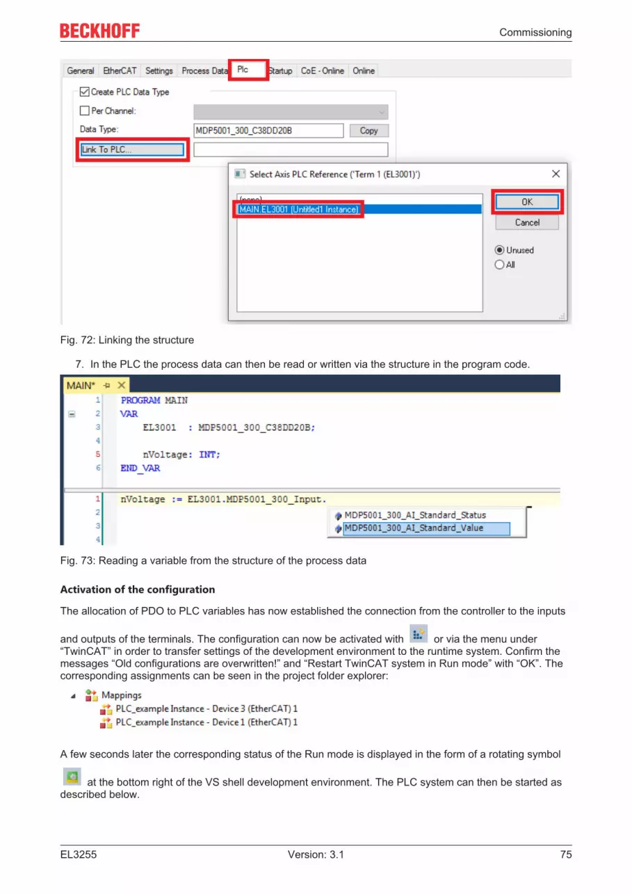
Commissioning
EL3255 75Version: 3.1
Fig. 72: Linking the structure
7. In the PLC the process data can then be read or written via the structure in the program code.
Fig. 73: Reading a variable from the structure of the process data
Activation of the configuration
The allocation of PDO to PLC variables has now established the connection from the controller to the inputs
and outputs of the terminals. The configuration can now be activated with or via the menu under“TwinCAT” in order to transfer settings of the development environment to the runtime system. Confirm themessages “Old configurations are overwritten!” and “Restart TwinCAT system in Run mode” with “OK”. Thecorresponding assignments can be seen in the project folder explorer:
A few seconds later the corresponding status of the Run mode is displayed in the form of a rotating symbol
at the bottom right of the VS shell development environment. The PLC system can then be started asdescribed below.

Commissioning
EL325576 Version: 3.1
Starting the controller
Select the menu option “PLC” → “Login” or click on to link the PLC with the real-time system and loadthe control program for execution. This results in the message No program on the controller! Should the newprogram be loaded?, which should be acknowledged with “Yes”. The runtime environment is ready for
program start by click on symbol , the “F5” key or via “PLC” in the menu selecting “Start”. The startedprogramming environment shows the runtime values of individual variables:
Fig. 74: TwinCAT development environment (VS shell): logged-in, after program startup
The two operator control elements for stopping and logout result in the required action(accordingly also for stop “Shift + F5”, or both actions can be selected via the PLC menu).

Commissioning
EL3255 77Version: 3.1
5.3 TwinCAT Development EnvironmentThe Software for automation TwinCAT (The Windows Control and Automation Technology) will bedistinguished into:
• TwinCAT 2: System Manager (Configuration) & PLC Control (Programming)• TwinCAT 3: Enhancement of TwinCAT 2 (Programming and Configuration takes place via a common
Development Environment)
Details:• TwinCAT 2:
◦ Connects I/O devices to tasks in a variable-oriented manner◦ Connects tasks to tasks in a variable-oriented manner◦ Supports units at the bit level◦ Supports synchronous or asynchronous relationships◦ Exchange of consistent data areas and process images◦ Datalink on NT - Programs by open Microsoft Standards (OLE, OCX, ActiveX, DCOM+, etc.)◦ Integration of IEC 61131-3-Software-SPS, Software- NC and Software-CNC within Windows
NT/2000/XP/Vista, Windows 7, NT/XP Embedded, CE◦ Interconnection to all common fieldbusses
◦ More…
Additional features:• TwinCAT 3 (eXtended Automation):
◦ Visual-Studio®-Integration◦ Choice of the programming language◦ Supports object orientated extension of IEC 61131-3◦ Usage of C/C++ as programming language for real time applications◦ Connection to MATLAB®/Simulink®◦ Open interface for expandability◦ Flexible run-time environment◦ Active support of Multi-Core- and 64-Bit-Operatingsystem◦ Automatic code generation and project creation with the TwinCAT Automation Interface
◦ More…
Within the following sections commissioning of the TwinCAT Development Environment on a PC System forthe control and also the basically functions of unique control elements will be explained.
Please see further information to TwinCAT 2 and TwinCAT 3 at http://infosys.beckhoff.com.
5.3.1 Installation of the TwinCAT real-time driverIn order to assign real-time capability to a standard Ethernet port of an IPC controller, the Beckhoff real-timedriver has to be installed on this port under Windows.
This can be done in several ways. One option is described here.
In the System Manager call up the TwinCAT overview of the local network interfaces via Options → ShowReal Time Ethernet Compatible Devices.

Commissioning
EL325578 Version: 3.1
Fig. 75: System Manager “Options” (TwinCAT 2)
This have to be called up by the menu “TwinCAT” within the TwinCAT 3 environment:
Fig. 76: Call up under VS Shell (TwinCAT 3)
The following dialog appears:
Fig. 77: Overview of network interfaces
Interfaces listed under “Compatible devices” can be assigned a driver via the “Install” button. A driver shouldonly be installed on compatible devices.
A Windows warning regarding the unsigned driver can be ignored.
Alternatively an EtherCAT-device can be inserted first of all as described in chapter Offline configurationcreation, section “Creating the EtherCAT device” [} 88] in order to view the compatible ethernet ports via itsEtherCAT properties (tab “Adapter”, button “Compatible Devices…”):

Commissioning
EL3255 79Version: 3.1
Fig. 78: EtherCAT device properties(TwinCAT 2): click on “Compatible Devices…” of tab “Adapte””
TwinCAT 3: the properties of the EtherCAT device can be opened by double click on “Device .. (EtherCAT)”within the Solution Explorer under “I/O”:
After the installation the driver appears activated in the Windows overview for the network interface(Windows Start → System Properties → Network)
Fig. 79: Windows properties of the network interface
A correct setting of the driver could be:

Commissioning
EL325580 Version: 3.1
Fig. 80: Exemplary correct driver setting for the Ethernet port
Other possible settings have to be avoided:

Commissioning
EL3255 81Version: 3.1
Fig. 81: Incorrect driver settings for the Ethernet port

Commissioning
EL325582 Version: 3.1
IP address of the port used
IP address/DHCPIn most cases an Ethernet port that is configured as an EtherCAT device will not transport generalIP packets. For this reason and in cases where an EL6601 or similar devices are used it is useful tospecify a fixed IP address for this port via the “Internet Protocol TCP/IP” driver setting and to disableDHCP. In this way the delay associated with the DHCP client for the Ethernet port assigning itself adefault IP address in the absence of a DHCP server is avoided. A suitable address space is192.168.x.x, for example.
Fig. 82: TCP/IP setting for the Ethernet port

Commissioning
EL3255 83Version: 3.1
5.3.2 Notes regarding ESI device description
Installation of the latest ESI device description
The TwinCAT EtherCAT master/System Manager needs the device description files for the devices to beused in order to generate the configuration in online or offline mode. The device descriptions are containedin the so-called ESI files (EtherCAT Slave Information) in XML format. These files can be requested from therespective manufacturer and are made available for download. An *.xml file may contain several devicedescriptions.
The ESI files for Beckhoff EtherCAT devices are available on the Beckhoff website.
The ESI files should be stored in the TwinCAT installation directory.
Default settings:
• TwinCAT 2: C:\TwinCAT\IO\EtherCAT• TwinCAT 3: C:\TwinCAT\3.1\Config\Io\EtherCAT
The files are read (once) when a new System Manager window is opened, if they have changed since thelast time the System Manager window was opened.
A TwinCAT installation includes the set of Beckhoff ESI files that was current at the time when the TwinCATbuild was created.
For TwinCAT 2.11/TwinCAT 3 and higher, the ESI directory can be updated from the System Manager, if theprogramming PC is connected to the Internet; by
• TwinCAT 2: Option → “Update EtherCAT Device Descriptions”• TwinCAT 3: TwinCAT → EtherCAT Devices → “Update Device Descriptions (via ETG Website)…”
The TwinCAT ESI Updater [} 87] is available for this purpose.
ESIThe *.xml files are associated with *.xsd files, which describe the structure of the ESI XML files. Toupdate the ESI device descriptions, both file types should therefore be updated.
Device differentiation
EtherCAT devices/slaves are distinguished by four properties, which determine the full device identifier. Forexample, the device identifier EL2521-0025-1018 consists of:
• family key “EL”• name “2521”• type “0025”• and revision “1018”
Fig. 83: Identifier structure
The order identifier consisting of name + type (here: EL2521-0010) describes the device function. Therevision indicates the technical progress and is managed by Beckhoff. In principle, a device with a higherrevision can replace a device with a lower revision, unless specified otherwise, e.g. in the documentation.Each revision has its own ESI description. See further notes [} 9].

Commissioning
EL325584 Version: 3.1
Online description
If the EtherCAT configuration is created online through scanning of real devices (see section Online setup)and no ESI descriptions are available for a slave (specified by name and revision) that was found, theSystem Manager asks whether the description stored in the device should be used. In any case, the SystemManager needs this information for setting up the cyclic and acyclic communication with the slave correctly.
Fig. 84: OnlineDescription information window (TwinCAT 2)
In TwinCAT 3 a similar window appears, which also offers the Web update:
Fig. 85: Information window OnlineDescription (TwinCAT 3)
If possible, the Yes is to be rejected and the required ESI is to be requested from the device manufacturer.After installation of the XML/XSD file the configuration process should be repeated.
NOTEChanging the “usual” configuration through a scanü If a scan discovers a device that is not yet known to TwinCAT, distinction has to be made between two
cases. Taking the example here of the EL2521-0000 in the revision 1019a) no ESI is present for the EL2521-0000 device at all, either for the revision 1019 or for an older revision.
The ESI must then be requested from the manufacturer (in this case Beckhoff).b) an ESI is present for the EL2521-0000 device, but only in an older revision, e.g. 1018 or 1017.
In this case an in-house check should first be performed to determine whether the spare parts stock al-lows the integration of the increased revision into the configuration at all. A new/higher revision usuallyalso brings along new features. If these are not to be used, work can continue without reservations withthe previous revision 1018 in the configuration. This is also stated by the Beckhoff compatibility rule.
Refer in particular to the chapter “General notes on the use of Beckhoff EtherCAT IO components” and formanual configuration to the chapter “Offline configuration creation [} 88]”.
If the OnlineDescription is used regardless, the System Manager reads a copy of the device description fromthe EEPROM in the EtherCAT slave. In complex slaves the size of the EEPROM may not be sufficient for thecomplete ESI, in which case the ESI would be incomplete in the configurator. Therefore it’s recommendedusing an offline ESI file with priority in such a case.
The System Manager creates for online recorded device descriptions a new file“OnlineDescription0000...xml” in its ESI directory, which contains all ESI descriptions that were read online.

Commissioning
EL3255 85Version: 3.1
Fig. 86: File OnlineDescription.xml created by the System Manager
Is a slave desired to be added manually to the configuration at a later stage, online created slaves areindicated by a prepended symbol “>” in the selection list (see Figure Indication of an online recorded ESI ofEL2521 as an example).
Fig. 87: Indication of an online recorded ESI of EL2521 as an example
If such ESI files are used and the manufacturer's files become available later, the file OnlineDescription.xmlshould be deleted as follows:
• close all System Manager windows• restart TwinCAT in Config mode• delete “OnlineDescription0000...xml”• restart TwinCAT System Manager
This file should not be visible after this procedure, if necessary press <F5> to update
OnlineDescription for TwinCAT 3.xIn addition to the file described above “OnlineDescription0000...xml”, a so called EtherCAT cachewith new discovered devices is created by TwinCAT 3.x, e.g. under Windows 7:
(Please note the language settings of the OS!)You have to delete this file, too.
Faulty ESI file
If an ESI file is faulty and the System Manager is unable to read it, the System Manager brings up aninformation window.
Fig. 88: Information window for faulty ESI file (left: TwinCAT 2; right: TwinCAT 3)

Commissioning
EL325586 Version: 3.1
Reasons may include:
• Structure of the *.xml does not correspond to the associated *.xsd file → check your schematics• Contents cannot be translated into a device description → contact the file manufacturer

Commissioning
EL3255 87Version: 3.1
5.3.3 TwinCAT ESI UpdaterFor TwinCAT 2.11 and higher, the System Manager can search for current Beckhoff ESI files automatically, ifan online connection is available:
Fig. 89: Using the ESI Updater (>= TwinCAT 2.11)
The call up takes place under:“Options” → “Update EtherCAT Device Descriptions”
Selection under TwinCAT 3:
Fig. 90: Using the ESI Updater (TwinCAT 3)
The ESI Updater (TwinCAT 3) is a convenient option for automatic downloading of ESI data provided byEtherCAT manufacturers via the Internet into the TwinCAT directory (ESI = EtherCAT slave information).TwinCAT accesses the central ESI ULR directory list stored at ETG; the entries can then be viewed in theUpdater dialog, although they cannot be changed there.
The call up takes place under:“TwinCAT” → “EtherCAT Devices” → “Update Device Description (via ETG Website)…”.
5.3.4 Distinction between Online and OfflineThe distinction between online and offline refers to the presence of the actual I/O environment (drives,terminals, EJ-modules). If the configuration is to be prepared in advance of the system configuration as aprogramming system, e.g. on a laptop, this is only possible in “Offline configuration” mode. In this case allcomponents have to be entered manually in the configuration, e.g. based on the electrical design.
If the designed control system is already connected to the EtherCAT system and all components areenergised and the infrastructure is ready for operation, the TwinCAT configuration can simply be generatedthrough “scanning” from the runtime system. This is referred to as online configuration.
In any case, during each startup the EtherCAT master checks whether the slaves it finds match theconfiguration. This test can be parameterised in the extended slave settings. Refer to note “Installation ofthe latest ESI-XML device description” [} 83].
For preparation of a configuration:• the real EtherCAT hardware (devices, couplers, drives) must be present and installed• the devices/modules must be connected via EtherCAT cables or in the terminal/ module strand in the
same way as they are intended to be used later

Commissioning
EL325588 Version: 3.1
• the devices/modules be connected to the power supply and ready for communication• TwinCAT must be in CONFIG mode on the target system.
The online scan process consists of:
• detecting the EtherCAT device [} 93] (Ethernet port at the IPC)
• detecting the connected EtherCAT devices [} 94]. This step can be carried out independent of thepreceding step
• troubleshooting [} 97]
The scan with existing configuration [} 98] can also be carried out for comparison.
5.3.5 OFFLINE configuration creation
Creating the EtherCAT device
Create an EtherCAT device in an empty System Manager window.
Fig. 91: Append EtherCAT device (left: TwinCAT 2; right: TwinCAT 3)
Select type “EtherCAT” for an EtherCAT I/O application with EtherCAT slaves. For the present publisher/subscriber service in combination with an EL6601/EL6614 terminal select “EtherCAT Automation Protocolvia EL6601”.
Fig. 92: Selecting the EtherCAT connection (TwinCAT 2.11, TwinCAT 3)
Then assign a real Ethernet port to this virtual device in the runtime system.
Fig. 93: Selecting the Ethernet port

Commissioning
EL3255 89Version: 3.1
This query may appear automatically when the EtherCAT device is created, or the assignment can be set/modified later in the properties dialog; see Fig. “EtherCAT device properties (TwinCAT 2)”.
Fig. 94: EtherCAT device properties (TwinCAT 2)
TwinCAT 3: the properties of the EtherCAT device can be opened by double click on “Device .. (EtherCAT)”within the Solution Explorer under “I/O”:
Selecting the Ethernet portEthernet ports can only be selected for EtherCAT devices for which the TwinCAT real-time driver isinstalled. This has to be done separately for each port. Please refer to the respective installationpage [} 77].
Defining EtherCAT slaves
Further devices can be appended by right-clicking on a device in the configuration tree.
Fig. 95: Appending EtherCAT devices (left: TwinCAT 2; right: TwinCAT 3)
The dialog for selecting a new device opens. Only devices for which ESI files are available are displayed.
Only devices are offered for selection that can be appended to the previously selected device. Therefore thephysical layer available for this port is also displayed (Fig. “Selection dialog for new EtherCAT device”, A). Inthe case of cable-based Fast-Ethernet physical layer with PHY transfer, then also only cable-based devicesare available, as shown in Fig. “Selection dialog for new EtherCAT device”. If the preceding device hasseveral free ports (e.g. EK1122 or EK1100), the required port can be selected on the right-hand side (A).
Overview of physical layer
• “Ethernet”: cable-based 100BASE-TX: EK couplers, EP boxes, devices with RJ45/M8/M12 connector

Commissioning
EL325590 Version: 3.1
• “E-Bus”: LVDS “terminal bus”, “EJ-module”: EL/ES terminals, various modular modules
The search field facilitates finding specific devices (since TwinCAT 2.11 or TwinCAT 3).
Fig. 96: Selection dialog for new EtherCAT device
By default only the name/device type is used as selection criterion. For selecting a specific revision of thedevice the revision can be displayed as “Extended Information”.
Fig. 97: Display of device revision
In many cases several device revisions were created for historic or functional reasons, e.g. throughtechnological advancement. For simplification purposes (see Fig. “Selection dialog for new EtherCATdevice”) only the last (i.e. highest) revision and therefore the latest state of production is displayed in theselection dialog for Beckhoff devices. To show all device revisions available in the system as ESIdescriptions tick the “Show Hidden Devices” check box, see Fig. “Display of previous revisions”.

Commissioning
EL3255 91Version: 3.1
Fig. 98: Display of previous revisions
Device selection based on revision, compatibilityThe ESI description also defines the process image, the communication type between master andslave/device and the device functions, if applicable. The physical device (firmware, if available) hasto support the communication queries/settings of the master. This is backward compatible, i.e.newer devices (higher revision) should be supported if the EtherCAT master addresses them as anolder revision. The following compatibility rule of thumb is to be assumed for Beckhoff EtherCATTerminals/ Boxes/ EJ-modules:device revision in the system >= device revision in the configurationThis also enables subsequent replacement of devices without changing the configuration (differentspecifications are possible for drives).
Example
If an EL2521-0025-1018 is specified in the configuration, an EL2521-0025-1018 or higher (-1019, -1020) canbe used in practice.
Fig. 99: Name/revision of the terminal
If current ESI descriptions are available in the TwinCAT system, the last revision offered in the selectiondialog matches the Beckhoff state of production. It is recommended to use the last device revision whencreating a new configuration, if current Beckhoff devices are used in the real application. Older revisionsshould only be used if older devices from stock are to be used in the application.
In this case the process image of the device is shown in the configuration tree and can be parameterized asfollows: linking with the task, CoE/DC settings, plug-in definition, startup settings, ...

Commissioning
EL325592 Version: 3.1
Fig. 100: EtherCAT terminal in the TwinCAT tree (left: TwinCAT 2; right: TwinCAT 3)

Commissioning
EL3255 93Version: 3.1
5.3.6 ONLINE configuration creation
Detecting/scanning of the EtherCAT device
The online device search can be used if the TwinCAT system is in CONFIG mode. This can be indicated bya symbol right below in the information bar:
• on TwinCAT 2 by a blue display “Config Mode” within the System Manager window: .
• on TwinCAT 3 within the user interface of the development environment by a symbol .
TwinCAT can be set into this mode:
• TwinCAT 2: by selection of in the Menubar or by “Actions” → “Set/Reset TwinCAT to ConfigMode…”
• TwinCAT 3: by selection of in the Menubar or by “TwinCAT” → “Restart TwinCAT (Config Mode)”
Online scanning in Config modeThe online search is not available in RUN mode (production operation). Note the differentiation be-tween TwinCAT programming system and TwinCAT target system.
The TwinCAT 2 icon ( ) or TwinCAT 3 icon ( ) within the Windows-Taskbar always shows theTwinCAT mode of the local IPC. Compared to that, the System Manager window of TwinCAT 2 or the userinterface of TwinCAT 3 indicates the state of the target system.
Fig. 101: Differentiation local/target system (left: TwinCAT 2; right: TwinCAT 3)
Right-clicking on “I/O Devices” in the configuration tree opens the search dialog.
Fig. 102: Scan Devices (left: TwinCAT 2; right: TwinCAT 3)
This scan mode attempts to find not only EtherCAT devices (or Ethernet ports that are usable as such), butalso NOVRAM, fieldbus cards, SMB etc. However, not all devices can be found automatically.
Fig. 103: Note for automatic device scan (left: TwinCAT 2; right: TwinCAT 3)

Commissioning
EL325594 Version: 3.1
Ethernet ports with installed TwinCAT real-time driver are shown as “RT Ethernet” devices. An EtherCATframe is sent to these ports for testing purposes. If the scan agent detects from the response that anEtherCAT slave is connected, the port is immediately shown as an “EtherCAT Device” .
Fig. 104: Detected Ethernet devices
Via respective checkboxes devices can be selected (as illustrated in Fig. “Detected Ethernet devices” e.g.Device 3 and Device 4 were chosen). After confirmation with “OK” a device scan is suggested for all selecteddevices, see Fig.: “Scan query after automatic creation of an EtherCAT device”.
Selecting the Ethernet portEthernet ports can only be selected for EtherCAT devices for which the TwinCAT real-time driver isinstalled. This has to be done separately for each port. Please refer to the respective installationpage [} 77].
Detecting/Scanning the EtherCAT devices
Online scan functionalityDuring a scan the master queries the identity information of the EtherCAT slaves from the slaveEEPROM. The name and revision are used for determining the type. The respective devices are lo-cated in the stored ESI data and integrated in the configuration tree in the default state definedthere.
Fig. 105: Example default state
NOTESlave scanning in practice in series machine productionThe scanning function should be used with care. It is a practical and fast tool for creating an initial configu-ration as a basis for commissioning. In series machine production or reproduction of the plant, however, thefunction should no longer be used for the creation of the configuration, but if necessary for comparison[} 98] with the defined initial configuration.Background: since Beckhoff occasionally increases the revisionversion of the delivered products for product maintenance reasons, a configuration can be created by sucha scan which (with an identical machine construction) is identical according to the device list; however, therespective device revision may differ from the initial configuration.
Example:
Company A builds the prototype of a machine B, which is to be produced in series later on. To do this theprototype is built, a scan of the IO devices is performed in TwinCAT and the initial configuration “B.tsm” iscreated. The EL2521-0025 EtherCAT terminal with the revision 1018 is located somewhere. It is thus builtinto the TwinCAT configuration in this way:

Commissioning
EL3255 95Version: 3.1
Fig. 106: Installing EthetCAT terminal with revision -1018
Likewise, during the prototype test phase, the functions and properties of this terminal are tested by theprogrammers/commissioning engineers and used if necessary, i.e. addressed from the PLC “B.pro” or theNC. (the same applies correspondingly to the TwinCAT 3 solution files).
The prototype development is now completed and series production of machine B starts, for which Beckhoffcontinues to supply the EL2521-0025-0018. If the commissioning engineers of the series machine productiondepartment always carry out a scan, a B configuration with the identical contents results again for eachmachine. Likewise, A might create spare parts stores worldwide for the coming series-produced machineswith EL2521-0025-1018 terminals.
After some time Beckhoff extends the EL2521-0025 by a new feature C. Therefore the FW is changed,outwardly recognizable by a higher FW version and a new revision -1019. Nevertheless the new devicenaturally supports functions and interfaces of the predecessor version(s); an adaptation of “B.tsm” or even“B.pro” is therefore unnecessary. The series-produced machines can continue to be built with “B.tsm” and“B.pro”; it makes sense to perform a comparative scan [} 98] against the initial configuration “B.tsm” in orderto check the built machine.
However, if the series machine production department now doesn’t use “B.tsm”, but instead carries out ascan to create the productive configuration, the revision -1019 is automatically detected and built into theconfiguration:
Fig. 107: Detection of EtherCAT terminal with revision -1019
This is usually not noticed by the commissioning engineers. TwinCAT cannot signal anything either, sincevirtually a new configuration is created. According to the compatibility rule, however, this means that noEL2521-0025-1018 should be built into this machine as a spare part (even if this nevertheless works in thevast majority of cases).
In addition, it could be the case that, due to the development accompanying production in company A, thenew feature C of the EL2521-0025-1019 (for example, an improved analog filter or an additional processdata for the diagnosis) is discovered and used without in-house consultation. The previous stock of sparepart devices are then no longer to be used for the new configuration “B2.tsm” created in this way. Þ if seriesmachine production is established, the scan should only be performed for informative purposes forcomparison with a defined initial configuration. Changes are to be made with care!
If an EtherCAT device was created in the configuration (manually or through a scan), the I/O field can bescanned for devices/slaves.
Fig. 108: Scan query after automatic creation of an EtherCAT device (left: TwinCAT 2; right: TwinCAT 3)
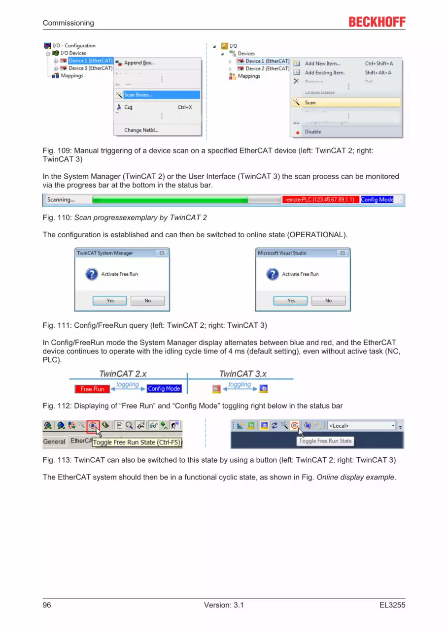
Commissioning
EL325596 Version: 3.1
Fig. 109: Manual triggering of a device scan on a specified EtherCAT device (left: TwinCAT 2; right:TwinCAT 3)
In the System Manager (TwinCAT 2) or the User Interface (TwinCAT 3) the scan process can be monitoredvia the progress bar at the bottom in the status bar.
Fig. 110: Scan progressexemplary by TwinCAT 2
The configuration is established and can then be switched to online state (OPERATIONAL).
Fig. 111: Config/FreeRun query (left: TwinCAT 2; right: TwinCAT 3)
In Config/FreeRun mode the System Manager display alternates between blue and red, and the EtherCATdevice continues to operate with the idling cycle time of 4 ms (default setting), even without active task (NC,PLC).
Fig. 112: Displaying of “Free Run” and “Config Mode” toggling right below in the status bar
Fig. 113: TwinCAT can also be switched to this state by using a button (left: TwinCAT 2; right: TwinCAT 3)
The EtherCAT system should then be in a functional cyclic state, as shown in Fig. Online display example.

Commissioning
EL3255 97Version: 3.1
Fig. 114: Online display example
Please note:
• all slaves should be in OP state• the EtherCAT master should be in “Actual State” OP• “frames/sec” should match the cycle time taking into account the sent number of frames• no excessive “LostFrames” or CRC errors should occur
The configuration is now complete. It can be modified as described under manual procedure [} 88].
Troubleshooting
Various effects may occur during scanning.
• An unknown device is detected, i.e. an EtherCAT slave for which no ESI XML description is available.In this case the System Manager offers to read any ESI that may be stored in the device. This case isdescribed in the chapter “Notes regarding ESI device description”.
• Device are not detected properlyPossible reasons include:
◦ faulty data links, resulting in data loss during the scan◦ slave has invalid device description
The connections and devices should be checked in a targeted manner, e.g. via the emergencyscan.Then re-run the scan.
Fig. 115: Faulty identification
In the System Manager such devices may be set up as EK0000 or unknown devices. Operation is notpossible or meaningful.

Commissioning
EL325598 Version: 3.1
Scan over existing Configuration
NOTEChange of the configuration after comparisonWith this scan (TwinCAT 2.11 or 3.1) only the device properties vendor (manufacturer), device name andrevision are compared at present! A “ChangeTo” or “Copy” should only be carried out with care, taking intoconsideration the Beckhoff IO compatibility rule (see above). The device configuration is then replaced bythe revision found; this can affect the supported process data and functions.
If a scan is initiated for an existing configuration, the actual I/O environment may match the configurationexactly or it may differ. This enables the configuration to be compared.
Fig. 116: Identical configuration (left: TwinCAT 2; right: TwinCAT 3)
If differences are detected, they are shown in the correction dialog, so that the user can modify theconfiguration as required.
Fig. 117: Correction dialog
It is advisable to tick the “Extended Information” check box to reveal differences in the revision.

Commissioning
EL3255 99Version: 3.1
Color Explanationgreen This EtherCAT slave matches the entry on the other side. Both type and revision match.blue This EtherCAT slave is present on the other side, but in a different revision. This other revision can
have other default values for the process data as well as other/additional functions.If the found revision is higher than the configured revision, the slave may be used providedcompatibility issues are taken into account.If the found revision is lower than the configured revision, it is likely that the slave cannot be used.The found device may not support all functions that the master expects based on the higherrevision number.
lightblue
This EtherCAT slave is ignored (“Ignore” button)
red • This EtherCAT slave is not present on the other side.• It is present, but in a different revision, which also differs in its properties from the one specified.
The compatibility principle then also applies here: if the found revision is higher than theconfigured revision, use is possible provided compatibility issues are taken into account, sincethe successor devices should support the functions of the predecessor devices. If the found revision is lower than the configured revision, it is likely that the slave cannot beused. The found device may not support all functions that the master expects based on thehigher revision number.
Device selection based on revision, compatibilityThe ESI description also defines the process image, the communication type between master andslave/device and the device functions, if applicable. The physical device (firmware, if available) hasto support the communication queries/settings of the master. This is backward compatible, i.e.newer devices (higher revision) should be supported if the EtherCAT master addresses them as anolder revision. The following compatibility rule of thumb is to be assumed for Beckhoff EtherCATTerminals/ Boxes/ EJ-modules:device revision in the system >= device revision in the configurationThis also enables subsequent replacement of devices without changing the configuration (differentspecifications are possible for drives).
Example
If an EL2521-0025-1018 is specified in the configuration, an EL2521-0025-1018 or higher (-1019, -1020) canbe used in practice.
Fig. 118: Name/revision of the terminal
If current ESI descriptions are available in the TwinCAT system, the last revision offered in the selectiondialog matches the Beckhoff state of production. It is recommended to use the last device revision whencreating a new configuration, if current Beckhoff devices are used in the real application. Older revisionsshould only be used if older devices from stock are to be used in the application.
In this case the process image of the device is shown in the configuration tree and can be parameterized asfollows: linking with the task, CoE/DC settings, plug-in definition, startup settings, ...

Commissioning
EL3255100 Version: 3.1
Fig. 119: Correction dialog with modifications
Once all modifications have been saved or accepted, click “OK” to transfer them to the real *.tsmconfiguration.
Change to Compatible Type
TwinCAT offers a function Change to Compatible Type… for the exchange of a device whilst retaining thelinks in the task.
Fig. 120: Dialog “Change to Compatible Type…” (left: TwinCAT 2; right: TwinCAT 3)
The following elements in the ESI of an EtherCAT device are compared by TwinCAT and assumed to be thesame in order to decide whether a device is indicated as "compatible":
- Physics (e.g. RJ45, Ebus...)
- FMMU (additional ones are allowed)
- SyncManager (SM, additional ones are allowed)
- EoE (attributes MAC, IP)
- CoE (attributes SdoInfo, PdoAssign, PdoConfig, PdoUpload, CompleteAccess)
- FoE
- PDO (process data: Sequence, SyncUnit SU, SyncManager SM, EntryCount, Ent-ry.Datatype)
This function is preferably to be used on AX5000 devices.
Change to Alternative Type
The TwinCAT System Manager offers a function for the exchange of a device: Change to Alternative Type

Commissioning
EL3255 101Version: 3.1
Fig. 121: TwinCAT 2 Dialog Change to Alternative Type
If called, the System Manager searches in the procured device ESI (in this example: EL1202-0000) fordetails of compatible devices contained there. The configuration is changed and the ESI-EEPROM isoverwritten at the same time – therefore this process is possible only in the online state (ConfigMode).
5.3.7 EtherCAT subscriber configurationIn the left-hand window of the TwinCAT 2 System Manager or the Solution Explorer of the TwinCAT 3Development Environment respectively, click on the element of the terminal within the tree you wish toconfigure (in the example: EL3751 Terminal 3).
Fig. 122: Branch element as terminal EL3751
In the right-hand window of the TwinCAT System Manager (TwinCAT 2) or the Development Environment(TwinCAT 3), various tabs are now available for configuring the terminal. And yet the dimension ofcomplexity of a subscriber determines which tabs are provided. Thus as illustrated in the example above theterminal EL3751 provides many setup options and also a respective number of tabs are available. On thecontrary by the terminal EL1004 for example the tabs “General”, “EtherCAT”, “Process Data” and “Online“are available only. Several terminals, as for instance the EL6695 provide special functions by a tab with itsown terminal name, so “EL6695” in this case. A specific tab “Settings” by terminals with a wide range ofsetup options will be provided also (e.g. EL3751).
“General” tab
Fig. 123: “General” tab

Commissioning
EL3255102 Version: 3.1
Name Name of the EtherCAT deviceId Number of the EtherCAT deviceType EtherCAT device typeComment Here you can add a comment (e.g. regarding the system).Disabled Here you can deactivate the EtherCAT device.Create symbols Access to this EtherCAT slave via ADS is only available if this control box is
activated.
“EtherCAT” tab
Fig. 124: “EtherCAT” tab
Type EtherCAT device typeProduct/Revision Product and revision number of the EtherCAT deviceAuto Inc Addr. Auto increment address of the EtherCAT device. The auto increment address can
be used for addressing each EtherCAT device in the communication ring throughits physical position. Auto increment addressing is used during the start-up phasewhen the EtherCAT master allocates addresses to the EtherCAT devices. Withauto increment addressing the first EtherCAT slave in the ring has the address0000hex. For each further slave the address is decremented by 1 (FFFFhex, FFFEhexetc.).
EtherCAT Addr. Fixed address of an EtherCAT slave. This address is allocated by the EtherCATmaster during the start-up phase. Tick the control box to the left of the input field inorder to modify the default value.
Previous Port Name and port of the EtherCAT device to which this device is connected. If it ispossible to connect this device with another one without changing the order of theEtherCAT devices in the communication ring, then this combination field isactivated and the EtherCAT device to which this device is to be connected can beselected.
Advanced Settings This button opens the dialogs for advanced settings.
The link at the bottom of the tab points to the product page for this EtherCAT device on the web.
“Process Data” tab
Indicates the configuration of the process data. The input and output data of the EtherCAT slave arerepresented as CANopen process data objects (Process Data Objects, PDOs). The user can select a PDOvia PDO assignment and modify the content of the individual PDO via this dialog, if the EtherCAT slavesupports this function.
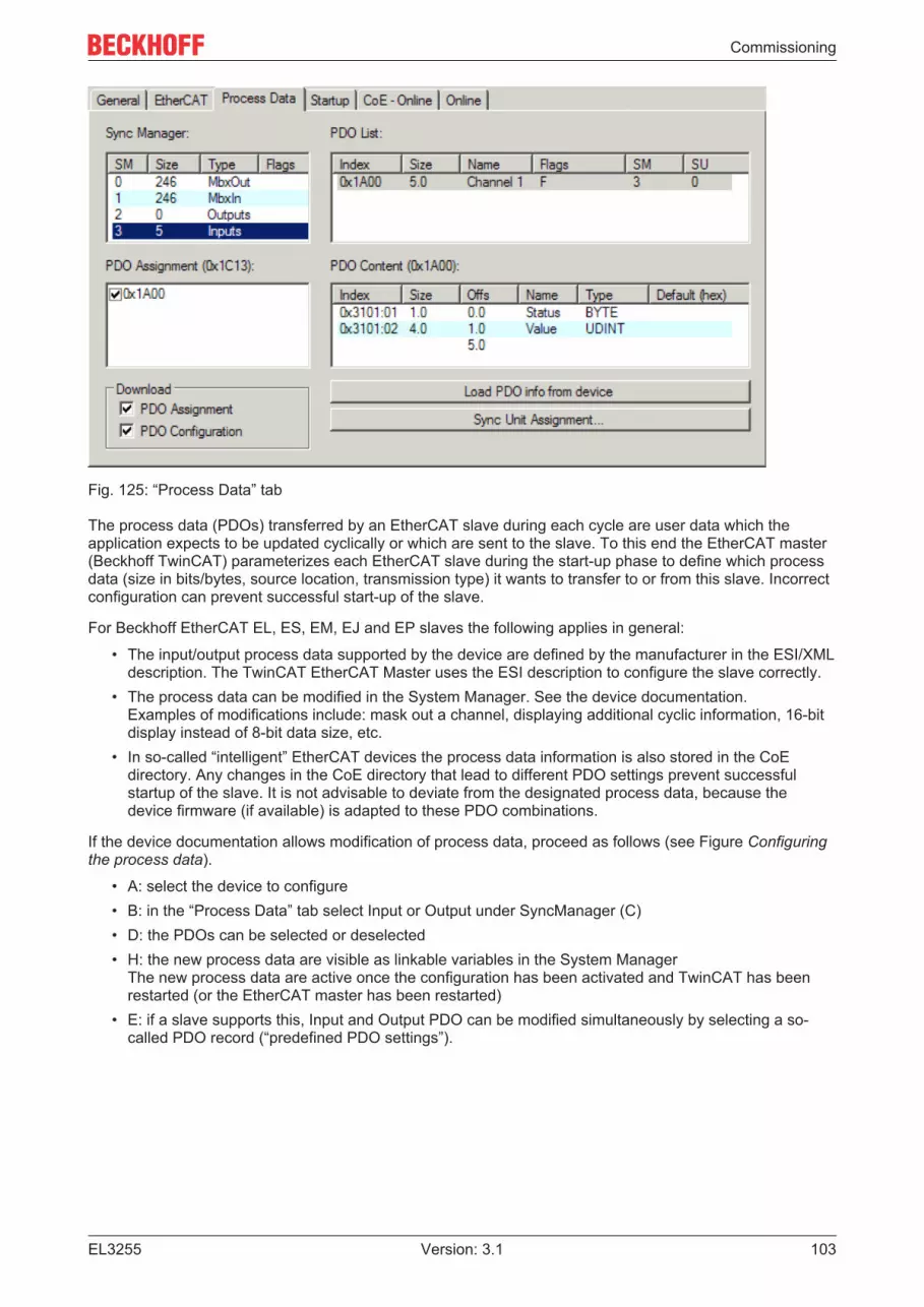
Commissioning
EL3255 103Version: 3.1
Fig. 125: “Process Data” tab
The process data (PDOs) transferred by an EtherCAT slave during each cycle are user data which theapplication expects to be updated cyclically or which are sent to the slave. To this end the EtherCAT master(Beckhoff TwinCAT) parameterizes each EtherCAT slave during the start-up phase to define which processdata (size in bits/bytes, source location, transmission type) it wants to transfer to or from this slave. Incorrectconfiguration can prevent successful start-up of the slave.
For Beckhoff EtherCAT EL, ES, EM, EJ and EP slaves the following applies in general:
• The input/output process data supported by the device are defined by the manufacturer in the ESI/XMLdescription. The TwinCAT EtherCAT Master uses the ESI description to configure the slave correctly.
• The process data can be modified in the System Manager. See the device documentation.Examples of modifications include: mask out a channel, displaying additional cyclic information, 16-bitdisplay instead of 8-bit data size, etc.
• In so-called “intelligent” EtherCAT devices the process data information is also stored in the CoEdirectory. Any changes in the CoE directory that lead to different PDO settings prevent successfulstartup of the slave. It is not advisable to deviate from the designated process data, because thedevice firmware (if available) is adapted to these PDO combinations.
If the device documentation allows modification of process data, proceed as follows (see Figure Configuringthe process data).
• A: select the device to configure• B: in the “Process Data” tab select Input or Output under SyncManager (C)• D: the PDOs can be selected or deselected• H: the new process data are visible as linkable variables in the System Manager
The new process data are active once the configuration has been activated and TwinCAT has beenrestarted (or the EtherCAT master has been restarted)
• E: if a slave supports this, Input and Output PDO can be modified simultaneously by selecting a so-called PDO record (“predefined PDO settings”).

Commissioning
EL3255104 Version: 3.1
Fig. 126: Configuring the process data
Manual modification of the process dataAccording to the ESI description, a PDO can be identified as “fixed” with the flag “F” in the PDOoverview (Fig. Configuring the process data, J). The configuration of such PDOs cannot bechanged, even if TwinCAT offers the associated dialog (“Edit”). In particular, CoE content cannot bedisplayed as cyclic process data. This generally also applies in cases where a device supportsdownload of the PDO configuration, “G”. In case of incorrect configuration the EtherCAT slave usu-ally refuses to start and change to OP state. The System Manager displays an “invalid SM cfg” log-ger message: This error message (“invalid SM IN cfg” or “invalid SM OUT cfg”) also indicates thereason for the failed start.
A detailed description [} 109] can be found at the end of this section.
“Startup” tab
The Startup tab is displayed if the EtherCAT slave has a mailbox and supports the CANopen over EtherCAT(CoE) or Servo drive over EtherCAT protocol. This tab indicates which download requests are sent to themailbox during startup. It is also possible to add new mailbox requests to the list display. The downloadrequests are sent to the slave in the same order as they are shown in the list.

Commissioning
EL3255 105Version: 3.1
Fig. 127: “Startup” tab
Column DescriptionTransition Transition to which the request is sent. This can either be
• the transition from pre-operational to safe-operational (PS), or• the transition from safe-operational to operational (SO).If the transition is enclosed in “<>” (e.g. <PS>), the mailbox request is fixed and cannot bemodified or deleted by the user.
Protocol Type of mailbox protocolIndex Index of the objectData Date on which this object is to be downloaded.Comment Description of the request to be sent to the mailbox
Move Up This button moves the selected request up by one position in the list.Move Down This button moves the selected request down by one position in the list.New This button adds a new mailbox download request to be sent during startup.Delete This button deletes the selected entry.Edit This button edits an existing request.
“CoE - Online” tab
The additional CoE - Online tab is displayed if the EtherCAT slave supports the CANopen over EtherCAT(CoE) protocol. This dialog lists the content of the object list of the slave (SDO upload) and enables the userto modify the content of an object from this list. Details for the objects of the individual EtherCAT devices canbe found in the device-specific object descriptions.
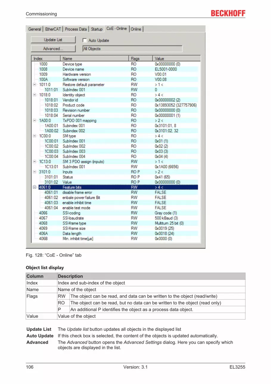
Commissioning
EL3255106 Version: 3.1
Fig. 128: “CoE - Online” tab
Object list display
Column DescriptionIndex Index and sub-index of the objectName Name of the objectFlags RW The object can be read, and data can be written to the object (read/write)
RO The object can be read, but no data can be written to the object (read only)P An additional P identifies the object as a process data object.
Value Value of the object
Update List The Update list button updates all objects in the displayed listAuto Update If this check box is selected, the content of the objects is updated automatically.Advanced The Advanced button opens the Advanced Settings dialog. Here you can specify which
objects are displayed in the list.

Commissioning
EL3255 107Version: 3.1
Fig. 129: Dialog “Advanced settings”
Online - via SDO Information If this option button is selected, the list of the objects included in the objectlist of the slave is uploaded from the slave via SDO information. The listbelow can be used to specify which object types are to be uploaded.
Offline - via EDS File If this option button is selected, the list of the objects included in the objectlist is read from an EDS file provided by the user.
“Online” tab
Fig. 130: “Online” tab

Commissioning
EL3255108 Version: 3.1
State Machine
Init This button attempts to set the EtherCAT device to the Init state.Pre-Op This button attempts to set the EtherCAT device to the pre-operational state.Op This button attempts to set the EtherCAT device to the operational state.Bootstrap This button attempts to set the EtherCAT device to the Bootstrap state.Safe-Op This button attempts to set the EtherCAT device to the safe-operational state.Clear Error This button attempts to delete the fault display. If an EtherCAT slave fails during
change of state it sets an error flag.Example: An EtherCAT slave is in PREOP state (pre-operational). The master nowrequests the SAFEOP state (safe-operational). If the slave fails during change ofstate it sets the error flag. The current state is now displayed as ERR PREOP.When the Clear Error button is pressed the error flag is cleared, and the currentstate is displayed as PREOP again.
Current State Indicates the current state of the EtherCAT device.Requested State Indicates the state requested for the EtherCAT device.
DLL Status
Indicates the DLL status (data link layer status) of the individual ports of the EtherCAT slave. The DLL statuscan have four different states:
Status DescriptionNo Carrier / Open No carrier signal is available at the port, but the port is open.No Carrier / Closed No carrier signal is available at the port, and the port is closed.Carrier / Open A carrier signal is available at the port, and the port is open.Carrier / Closed A carrier signal is available at the port, but the port is closed.
File Access over EtherCAT
Download With this button a file can be written to the EtherCAT device.Upload With this button a file can be read from the EtherCAT device.
“DC” tab (Distributed Clocks)
Fig. 131: “DC” tab (Distributed Clocks)
Operation Mode Options (optional):• FreeRun• SM-Synchron• DC-Synchron (Input based)• DC-Synchron
Advanced Settings… Advanced settings for readjustment of the real time determinant TwinCAT-clock
Detailed information to Distributed Clocks is specified on http://infosys.beckhoff.com:
Fieldbus Components → EtherCAT Terminals → EtherCAT System documentation → EtherCAT basics →Distributed Clocks

Commissioning
EL3255 109Version: 3.1
5.3.7.1 Detailed description of Process Data tab
Sync Manager
Lists the configuration of the Sync Manager (SM).If the EtherCAT device has a mailbox, SM0 is used for the mailbox output (MbxOut) and SM1 for the mailboxinput (MbxIn).SM2 is used for the output process data (outputs) and SM3 (inputs) for the input process data.
If an input is selected, the corresponding PDO assignment is displayed in the PDO Assignment list below.
PDO Assignment
PDO assignment of the selected Sync Manager. All PDOs defined for this Sync Manager type are listedhere:
• If the output Sync Manager (outputs) is selected in the Sync Manager list, all RxPDOs are displayed.• If the input Sync Manager (inputs) is selected in the Sync Manager list, all TxPDOs are displayed.
The selected entries are the PDOs involved in the process data transfer. In the tree diagram of the SystemManager these PDOs are displayed as variables of the EtherCAT device. The name of the variable isidentical to the Name parameter of the PDO, as displayed in the PDO list. If an entry in the PDO assignmentlist is deactivated (not selected and greyed out), this indicates that the input is excluded from the PDOassignment. In order to be able to select a greyed out PDO, the currently selected PDO has to be deselectedfirst.
Activation of PDO assignmentü If you have changed the PDO assignment, in order to activate the new PDO assignment,a) the EtherCAT slave has to run through the PS status transition cycle (from pre-operational to
safe-operational) once (see Online tab [} 107]),b) and the System Manager has to reload the EtherCAT slaves
( button for TwinCAT 2 or button for TwinCAT 3)
PDO list
List of all PDOs supported by this EtherCAT device. The content of the selected PDOs is displayed in thePDO Content list. The PDO configuration can be modified by double-clicking on an entry.
Column DescriptionIndex PDO index.Size Size of the PDO in bytes.Name Name of the PDO.
If this PDO is assigned to a Sync Manager, it appears as a variable of the slave with thisparameter as the name.
Flags F Fixed content: The content of this PDO is fixed and cannot be changed by theSystem Manager.
M Mandatory PDO. This PDO is mandatory and must therefore be assigned to aSync Manager! Consequently, this PDO cannot be deleted from the PDOAssignment list
SM Sync Manager to which this PDO is assigned. If this entry is empty, this PDO does not takepart in the process data traffic.
SU Sync unit to which this PDO is assigned.
PDO Content
Indicates the content of the PDO. If flag F (fixed content) of the PDO is not set the content can be modified.

Commissioning
EL3255110 Version: 3.1
Download
If the device is intelligent and has a mailbox, the configuration of the PDO and the PDO assignments can bedownloaded to the device. This is an optional feature that is not supported by all EtherCAT slaves.
PDO Assignment
If this check box is selected, the PDO assignment that is configured in the PDO Assignment list isdownloaded to the device on startup. The required commands to be sent to the device can be viewed in theStartup [} 104] tab.
PDO Configuration
If this check box is selected, the configuration of the respective PDOs (as shown in the PDO list and thePDO Content display) is downloaded to the EtherCAT slave.
5.3.8 Import/Export of EtherCAT devices with SCI and XTI
SCI and XTI Export/Import – Handling of user-defined modified EtherCAT slaves
5.3.8.1 Basic principles
An EtherCAT slave is basically parameterized through the following elements:
• Cyclic process data (PDO)• Synchronization (Distributed Clocks, FreeRun, SM-Synchron)• CoE parameters (acyclic object dictionary)
Note: Not all three elements may be present, depending on the slave.
For a better understanding of the export/import function, let's consider the usual procedure for IOconfiguration:
• The user/programmer processes the IO configuration in the TwinCAT system environment. Thisinvolves all input/output devices such as drives that are connected to the fieldbuses used.Note: In the following sections, only EtherCAT configurations in the TwinCAT system environment areconsidered.
• For example, the user manually adds devices to a configuration or performs a scan on the onlinesystem.
• This results in the IO system configuration.• On insertion, the slave appears in the system configuration in the default configuration provided by the
vendor, consisting of default PDO, default synchronization method and CoE StartUp parameter asdefined in the ESI (XML device description).
• If necessary, elements of the slave configuration can be changed, e.g. the PDO configuration or thesynchronization method, based on the respective device documentation.
It may become necessary to reuse the modified slave in other projects in this way, without having to makeequivalent configuration changes to the slave again. To accomplish this, proceed as follows:
• Export the slave configuration from the project,• Store and transport as a file,• Import into another EtherCAT project.
TwinCAT offers two methods for this purpose:
• within the TwinCAT environment: Export/Import as xti file or• outside, i.e. beyond the TwinCAT limits: Export/Import as sci file.

Commissioning
EL3255 111Version: 3.1
An example is provided below for illustration purposes: an EL3702 terminal with standard setting is switchedto 2-fold oversampling (blue) and the optional PDO "StartTimeNextLatch" is added (red):
The two methods for exporting and importing the modified terminal referred to above are demonstratedbelow.
5.3.8.2 Procedure within TwinCAT with xti files
Each IO device can be exported/saved individually:
The xti file can be stored:
and imported again in another TwinCAT system via "Insert Existing item":

Commissioning
EL3255112 Version: 3.1
5.3.8.3 Procedure within and outside TwinCAT with sci file
Note regarding availability (2021/01)
The SCI method is available from TwinCAT 3.1 build 4024.14.
The Slave Configuration Information (SCI) describes a specific complete configuration for an EtherCAT slave(terminal, box, drive...) based on the setting options of the device description file (ESI, EtherCAT SlaveInformation). That is, it includes PDO, CoE, synchronization.
Export:• select a single device via the menu (multiple selection is also possible):
TwinCAT → EtherCAT Devices → Export SCI.
• If TwinCAT is offline (i.e. if there is no connection to an actual running controller) a warning messagemay appear, because after executing the function the system attempts to reload the EtherCATsegment. However, in this case this is not relevant for the result and can be acknowledged by clickingOK:

Commissioning
EL3255 113Version: 3.1
• A description may also be provided:
• Explanation of the dialog box:
Name Name of the SCI, assigned by the user.Description Description of the slave configuration for the use case, assigned by the user.Options Keep modules If a slave supports modules/slots, the user can decide whether these are to be exported or
whether the module and device data are to be combined during export.AoE | Set AmsNetId The configured AmsNetId is exported. Usually this is network-dependent and cannot al-
ways be determined in advance.EoE | Set MAC and IP The configured virtual MAC and IP addresses are stored in the SCI. Usually these are net-
work-dependent and cannot always be determined in advance.CoE | Set cycletime(0x1C3x.2)
The configured cycle time is exported. Usually this is network-dependent and cannot al-ways be determined in advance.
ESI Reference to the original ESI file.Export Save SCI file.
• A list view is available for multiple selections (Export multiple SCI files):
• Selection of the slaves to be exported:◦ All:
All slaves are selected for export.

Commissioning
EL3255114 Version: 3.1
◦ None:All slaves are deselected.
• The sci file can be saved locally:
• The export takes place:
Import• An sci description can be inserted manually into the TwinCAT configuration like any normal Beckhoff
device description.• The sci file must be located in the TwinCAT ESI path, usually under:
C:\TwinCAT\3.1\Config\Io\EtherCAT
• Open the selection dialog:

Commissioning
EL3255 115Version: 3.1
• Display SCI devices and select and insert the desired device:
Additional Notes• Settings for the SCI function can be made via the general Options dialog
(Tools → Options → TwinCAT → Export SCI):
Explanation of the settings:
Default exportoptions
AoE | Set AmsNetId Default setting whether the configured AmsNetId is exported.CoE | Set cycle time(0x1C3x.2) Default setting whether the configured cycle time is exported.EoE | Set MAC and IP Default setting whether the configured MAC and IP addresses are exported.Keep modules Default setting whether the modules persist.
Generic Reload Devices Setting whether the Reload Devices command is executed before the SCI ex-port.This is strongly recommended to ensure a consistent slave configuration.

Commissioning
EL3255116 Version: 3.1
SCI error messages are displayed in the TwinCAT logger output window if required:

Commissioning
EL3255 117Version: 3.1
5.4 General Notes - EtherCAT Slave ApplicationThis summary briefly deals with a number of aspects of EtherCAT Slave operation under TwinCAT. Moredetailed information on this may be found in the corresponding sections of, for instance, the EtherCATSystem Documentation.
Diagnosis in real time: WorkingCounter, EtherCAT State and Status
Generally speaking an EtherCAT Slave provides a variety of diagnostic information that can be used by thecontrolling task.
This diagnostic information relates to differing levels of communication. It therefore has a variety of sources,and is also updated at various times.
Any application that relies on I/O data from a fieldbus being correct and up to date must make diagnosticaccess to the corresponding underlying layers. EtherCAT and the TwinCAT System Manager offercomprehensive diagnostic elements of this kind. Those diagnostic elements that are helpful to the controllingtask for diagnosis that is accurate for the current cycle when in operation (not during commissioning) arediscussed below.
Fig. 132: Selection of the diagnostic information of an EtherCAT Slave
In general, an EtherCAT Slave offers
• communication diagnosis typical for a slave (diagnosis of successful participation in the exchange ofprocess data, and correct operating mode)This diagnosis is the same for all slaves.
as well as• function diagnosis typical for a channel (device-dependent)
See the corresponding device documentation
The colors in Fig. Selection of the diagnostic information of an EtherCAT Slave also correspond to thevariable colors in the System Manager, see Fig. Basic EtherCAT Slave Diagnosis in the PLC.
Colour Meaningyellow Input variables from the Slave to the EtherCAT Master, updated in every cyclered Output variables from the Slave to the EtherCAT Master, updated in every cyclegreen Information variables for the EtherCAT Master that are updated acyclically. This means that
it is possible that in any particular cycle they do not represent the latest possible status. It istherefore useful to read such variables through ADS.

Commissioning
EL3255118 Version: 3.1
Fig. Basic EtherCAT Slave Diagnosis in the PLC shows an example of an implementation of basic EtherCATSlave Diagnosis. A Beckhoff EL3102 (2-channel analogue input terminal) is used here, as it offers both thecommunication diagnosis typical of a slave and the functional diagnosis that is specific to a channel.Structures are created as input variables in the PLC, each corresponding to the process image.
Fig. 133: Basic EtherCAT Slave Diagnosis in the PLC
The following aspects are covered here:
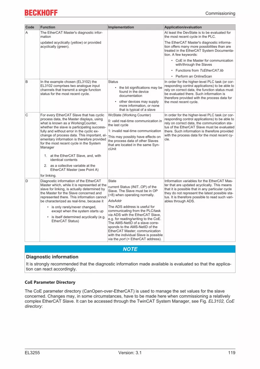
Commissioning
EL3255 119Version: 3.1
Code Function Implementation Application/evaluationA The EtherCAT Master's diagnostic infor-
mationupdated acyclically (yellow) or providedacyclically (green).
At least the DevState is to be evaluated forthe most recent cycle in the PLC.The EtherCAT Master's diagnostic informa-tion offers many more possibilities than aretreated in the EtherCAT System Documenta-tion. A few keywords:
• CoE in the Master for communicationwith/through the Slaves
• Functions from TcEtherCAT.lib
• Perform an OnlineScanB In the example chosen (EL3102) the
EL3102 comprises two analogue inputchannels that transmit a single functionstatus for the most recent cycle.
Status• the bit significations may be
found in the devicedocumentation
• other devices may supplymore information, or nonethat is typical of a slave
In order for the higher-level PLC task (or cor-responding control applications) to be able torely on correct data, the function status mustbe evaluated there. Such information istherefore provided with the process data forthe most recent cycle.
C For every EtherCAT Slave that has cyclicprocess data, the Master displays, usingwhat is known as a WorkingCounter,whether the slave is participating success-fully and without error in the cyclic ex-change of process data. This important, el-ementary information is therefore providedfor the most recent cycle in the SystemManager
1. at the EtherCAT Slave, and, withidentical contents
2. as a collective variable at theEtherCAT Master (see Point A)
for linking.
WcState (Working Counter)0: valid real-time communication inthe last cycle1: invalid real-time communicationThis may possibly have effects onthe process data of other Slavesthat are located in the same Syn-cUnit
In order for the higher-level PLC task (or cor-responding control applications) to be able torely on correct data, the communication sta-tus of the EtherCAT Slave must be evaluatedthere. Such information is therefore providedwith the process data for the most recent cy-cle.
D Diagnostic information of the EtherCATMaster which, while it is represented at theslave for linking, is actually determined bythe Master for the Slave concerned andrepresented there. This information cannotbe characterized as real-time, because it
• is only rarely/never changed,except when the system starts up
• is itself determined acyclically (e.g.EtherCAT Status)
Statecurrent Status (INIT..OP) of theSlave. The Slave must be in OP(=8) when operating normally.AdsAddr
The ADS address is useful forcommunicating from the PLC/taskvia ADS with the EtherCAT Slave,e.g. for reading/writing to the CoE.The AMS-NetID of a slave corre-sponds to the AMS-NetID of theEtherCAT Master; communicationwith the individual Slave is possiblevia the port (= EtherCAT address).
Information variables for the EtherCAT Mas-ter that are updated acyclically. This meansthat it is possible that in any particular cyclethey do not represent the latest possible sta-tus. It is therefore possible to read such vari-ables through ADS.
NOTEDiagnostic informationIt is strongly recommended that the diagnostic information made available is evaluated so that the applica-tion can react accordingly.
CoE Parameter Directory
The CoE parameter directory (CanOpen-over-EtherCAT) is used to manage the set values for the slaveconcerned. Changes may, in some circumstances, have to be made here when commissioning a relativelycomplex EtherCAT Slave. It can be accessed through the TwinCAT System Manager, see Fig. EL3102, CoEdirectory:

Commissioning
EL3255120 Version: 3.1
Fig. 134: EL3102, CoE directory
EtherCAT System DocumentationThe comprehensive description in the EtherCAT System Documentation (EtherCAT Basics --> CoEInterface) must be observed!
A few brief extracts:
• Whether changes in the online directory are saved locally in the slave depends on the device. ELterminals (except the EL66xx) are able to save in this way.
• The user must manage the changes to the StartUp list.
Commissioning aid in the TwinCAT System Manager
Commissioning interfaces are being introduced as part of an ongoing process for EL/EP EtherCAT devices.These are available in TwinCAT System Managers from TwinCAT 2.11R2 and above. They are integratedinto the System Manager through appropriately extended ESI configuration files.

Commissioning
EL3255 121Version: 3.1
Fig. 135: Example of commissioning aid for a EL3204
This commissioning process simultaneously manages
• CoE Parameter Directory• DC/FreeRun mode• the available process data records (PDO)
Although the “Process Data”, “DC”, “Startup” and “CoE-Online” that used to be necessary for this are stilldisplayed, it is recommended that, if the commissioning aid is used, the automatically generated settings arenot changed by it.
The commissioning tool does not cover every possible application of an EL/EP device. If the available settingoptions are not adequate, the user can make the DC, PDO and CoE settings manually, as in the past.
EtherCAT State: automatic default behaviour of the TwinCAT System Manager and manual operation
After the operating power is switched on, an EtherCAT Slave must go through the following statuses
• INIT• PREOP• SAFEOP• OP
to ensure sound operation. The EtherCAT Master directs these statuses in accordance with the initializationroutines that are defined for commissioning the device by the ES/XML and user settings (Distributed Clocks(DC), PDO, CoE). See also the section on "Principles of Communication, EtherCAT State Machine [} 21]" inthis connection. Depending how much configuration has to be done, and on the overall communication,booting can take up to a few seconds.
The EtherCAT Master itself must go through these routines when starting, until it has reached at least theOP target state.
The target state wanted by the user, and which is brought about automatically at start-up by TwinCAT, canbe set in the System Manager. As soon as TwinCAT reaches the status RUN, the TwinCAT EtherCATMaster will approach the target states.

Commissioning
EL3255122 Version: 3.1
Standard setting
The advanced settings of the EtherCAT Master are set as standard:
• EtherCAT Master: OP• Slaves: OP
This setting applies equally to all Slaves.
Fig. 136: Default behaviour of the System Manager
In addition, the target state of any particular Slave can be set in the “Advanced Settings” dialogue; thestandard setting is again OP.
Fig. 137: Default target state in the Slave
Manual Control
There are particular reasons why it may be appropriate to control the states from the application/task/PLC.For instance:

Commissioning
EL3255 123Version: 3.1
• for diagnostic reasons• to induce a controlled restart of axes• because a change in the times involved in starting is desirable
In that case it is appropriate in the PLC application to use the PLC function blocks from the TcEtherCAT.lib,which is available as standard, and to work through the states in a controlled manner using, for instance,FB_EcSetMasterState.
It is then useful to put the settings in the EtherCAT Master to INIT for master and slave.
Fig. 138: PLC function blocks
Note regarding E-Bus current
EL/ES terminals are placed on the DIN rail at a coupler on the terminal strand. A Bus Coupler can supply theEL terminals added to it with the E-bus system voltage of 5 V; a coupler is thereby loadable up to 2 A as arule. Information on how much current each EL terminal requires from the E-bus supply is available onlineand in the catalogue. If the added terminals require more current than the coupler can supply, then powerfeed terminals (e.g. EL9410) must be inserted at appropriate places in the terminal strand.
The pre-calculated theoretical maximum E-Bus current is displayed in the TwinCAT System Manager as acolumn value. A shortfall is marked by a negative total amount and an exclamation mark; a power feedterminal is to be placed before such a position.

Commissioning
EL3255124 Version: 3.1
Fig. 139: Illegally exceeding the E-Bus current
From TwinCAT 2.11 and above, a warning message “E-Bus Power of Terminal...” is output in the loggerwindow when such a configuration is activated:
Fig. 140: Warning message for exceeding E-Bus current
NOTECaution! Malfunction possible!The same ground potential must be used for the E-Bus supply of all EtherCAT terminals in a terminal block!

Commissioning
EL3255 125Version: 3.1
5.5 Basics about signal isolators, barriersOccasionally, analog signals cannot be fed directly from the sensor to the Beckhoff analog input terminal, inwhich case a special intermediary device must be added.
Reasons may include:
• The sensor may be installed in hazardous locations and protected according to the intrinsic safetyignition protection type (Ex i) while a Beckhoff ELX3xxx terminal is not yet available for the desiredapplication.
• Separate electrical isolation between the sensor and the Beckhoff terminal is required.• The sensor has an electrical output signal for which Beckhoff does not yet offer a suitable input
terminal.
The type of intermediate device depends on the following criteria
• Electrical signal supplied by the sensor? voltage 10 V or µV, AC or DC, 20 mA or 1 A, resistance, …• The sensor must be powered in some way, e.g.
◦ an IEPE sensor requires 2..8 mA constant current,◦ a resistor requires a measuring current,◦ an electronic sensor may need a 24V supply, or it may be fed via a 20 mA loop.
• What dynamic transmission quality for AC signals must the sensor provide via the intermediate device?Each intermediate device influences the analog signal, e.g. in terms of frequency-dependentattenuation, crosstalk, line resistance or bandwidth. This must be taken into account when anintermediate device is used in a metrological application.
• Is the device used for energy limitation in accordance with the intrinsic safety ignition protection type(Ex i)? In this case, a barrier with appropriate approval is required. Zener barriers are often used insuch situations. They are made up of resistors, fuses and Zener diodes.
As already mentioned, these can influence the analog signal quality with respect to the above features,e.g. by temperature-dependent change of the internal resistance.Terms: Zener barrier.
• Does it have to ensure electrical isolation of the analog signal?
Does electrical isolation of the analog signal have to be provided? Devices that electrically isolate thetransmitted signal reconfigure the signal, so that in this case special attention must be paid to thesignal influence. In this case the analog properties of the isolator and the Beckhoff analog terminal areinterlinked. The properties of the isolator are dominant, particularly when Beckhoff ELM measurementterminals or other high-quality analog terminals are used. On the output side, they typically supplystandard signals, such as 10 V or 20 mA. Compared with the use of external devices for electrical

Commissioning
EL3255126 Version: 3.1
isolation, the use of Beckhoff input terminals with channel-based electrical isolation is advantageous.Terms: signal isolator, signal converter, signal transducer, isolating amplifier, measuring amplifier, leveltransducer.
• Are both measures, i.e. explosion protection according to ignition protection type Ex i and electricalisolation necessary? In this case, so-called isolation barriers are used, which ensure energy limitationfor intrinsic safety and also electrical isolation of the signal. Please refer to the notes on analog signalinfluence referred to above.
From a metrological point of view, signal-influencing intermediate devices should be avoided if possible.

Commissioning
EL3255 127Version: 3.1
5.6 Notices on analog specificationsBeckhoff I/O devices (terminals, boxes, modules) with analog inputs are characterized by a number oftechnical characteristic data; refer to the technical data in the respective documents.
Some explanations are given below for the correct interpretation of these characteristic data.
5.6.1 Full scale value (FSV)An I/O device with an analog input measures over a nominal measuring range that is limited by an upper anda lower limit (initial value and end value); these can usually be taken from the device designation.The range between the two limits is called the measuring span and corresponds to the equation (end value -initial value). Analogous to pointing devices this is the measuring scale (see IEC 61131) or also the dynamicrange.
For analog I/O devices from Beckhoff the rule is that the limit with the largest value is chosen as the full scalevalue of the respective product (also called the reference value) and is given a positive sign. This applies toboth symmetrical and asymmetrical measuring spans.
Fig. 141: Full scale value, measuring span
For the above examples this means:
• Measuring range 0...10 V: asymmetric unipolar, full scale value = 10 V, measuring span = 10 V• Measuring range 4...20 mA: asymmetric unipolar, full scale value = 20 mA, measuring span = 16 mA• Measuring range -200...1370°C: asymmetric bipolar, full scale value = 1370°C, measuring
span = 1570°C• Measuring range -10...+10 V: symmetric bipolar, full scale value = 10 V, measuring span = 20 V
This applies to analog output terminals/ boxes (and related Beckhoff product groups).
5.6.2 Measuring error/ measurement deviationThe relative measuring error (% of the full scale value) is referenced to the full scale value and is calculatedas the quotient of the largest numerical deviation from the true value (‘measuring error’) referenced to the fullscale value.
The measuring error is generally valid for the entire permitted operating temperature range, also called the‘usage error limit’ and contains random and systematic portions of the referred device (i.e. ‘all’ influencessuch as temperature, inherent noise, aging, etc.).
It is always to be regarded as a positive/negative span with ±, even if it is specified without ± in some cases.

Commissioning
EL3255128 Version: 3.1
The maximum deviation can also be specified directly.
Example: Measuring range 0...10 V and measuring error < ± 0.3 % full scale value → maximum deviation ±30 mV in the permissible operating temperature range.
Lower measuring errorSince this specification also includes the temperature drift, a significantly lower measuring error canusually be assumed in case of a constant ambient temperature of the device and thermal stabiliza-tion after a user calibration.This applies to analog output devices.
5.6.3 Temperature coefficient tK [ppm/K]An electronic circuit is usually temperature dependent to a greater or lesser degree. In analog measurementtechnology this means that when a measured value is determined by means of an electronic circuit, itsdeviation from the “true” value is reproducibly dependent on the ambient/operating temperature.
A manufacturer can alleviate this by using components of a higher quality or by software means.
The temperature coefficient, when indicated, specified by Beckhoff allows the user to calculate the expectedmeasuring error outside the basic accuracy at 23 °C.
Due to the extensive uncertainty considerations that are incorporated in the determination of the basicaccuracy (at 23 °C), Beckhoff recommends a quadratic summation.
Example: Let the basic accuracy at 23 °C be ±0.01% typ. (full scale value), tK = 20 ppm/K typ.; the accuracyA35 at 35 °C is wanted, hence ΔT = 12 K
Remarks: ppm ≙ 10-6 % ≙ 10-2

Commissioning
EL3255 129Version: 3.1
5.6.4 Long-term useAnalog devices (inputs, outputs) are subject to constant environmental influences during operation(temperature, temperature change, shock/vibration, irradiation, etc.) This can affect the function, in particularthe analog accuracy (also: measurement or output uncertainty).
As industrial products, Beckhoff analog devices are designed for 24h/7d continuous operation.
The devices show that they generally comply with the accuracy specification, even in long-term use.However, as is usual for technical devices, an unlimited functional assurance (also applies to accuracy)cannot be given.
Beckhoff recommends checking the usability in relation to the application target within the scope of normalsystem maintenance, e.g. every 12-24 months.
5.6.5 Ground reference: single-ended/differential typificationFor analog inputs Beckhoff makes a basic distinction between two types: single-ended (SE) and differential(DIFF), referring to the difference in electrical connection with regard to the potential difference.
The diagram shows two-channel versions of an SE module and a DIFF module as examples for all multi-channel versions.
Fig. 142: SE and DIFF module as 2-channel version
Note: Dashed lines indicate that the respective connection may not necessarily be present in each SE orDIFF module. Electrical isolated channels are operating as differential type in general, hence there is nodirect relation (voltaic) to ground within the module established at all. Indeed, specified information torecommended and maximum voltage levels have to be taken into account.
The basic rule:
• Analog measurements always take the form of voltage measurements between two potential points.For voltage measurements a large R is used, in order to ensure a high impedance. For currentmeasurements a small R is used as shunt. If the purpose is resistance measurement, correspondingconsiderations are applied.

Commissioning
EL3255130 Version: 3.1
◦ Beckhoff generally refers to these two points as input+/signal potential and input-/referencepotential.
◦ For measurements between two potential points two potentials have to be supplied.◦ Regarding the terms “single-wire connection” or “three-wire connection”, please note the following
for pure analog measurements: three- or four-wire connections can be used for sensor supply, butare not involved in the actual analog measurement, which always takes place between twopotentials/wires.In particular this also applies to SE, even though the term suggest that only one wire is required.
• The term “electrical isolation” should be clarified in advance.Beckhoff IO modules feature 1..8 or more analog channels; with regard to the channel connection adistinction is made in terms of:
◦ how the channels WITHIN a module relate to each other, or◦ how the channels of SEVERAL modules relate to each other.
The property of electrical isolation indicates whether the channels are directly connected to eachother.
◦ Beckhoff terminals/ boxes (and related product groups) always feature electrical isolation betweenthe field/analog side and the bus/EtherCAT side. In other words, if two analog terminals/ boxes arenot connected via the power contacts (cable), the modules are effectively electrically isolated.
◦ If channels within a module are electrically isolated, or if a single-channel module has no powercontacts, the channels are effectively always differential. See also explanatory notes below.Differential channels are not necessarily electrically isolated.
• Analog measuring channels are subject to technical limits, both in terms of the recommended operatingrange (continuous operation) and the destruction limit. Please refer to the respective terminal/ boxdocumentation for further details.
Explanation• differential (DIFF)
◦ Differential measurement is the most flexible concept. The user can freely choose both connectionpoints, input+/signal potential and input-/reference potential, within the framework of the technicalspecification.
◦ A differential channel can also be operated as SE, if the reference potential of several sensors islinked. This interconnection may take place via the system GND.
◦ Since a differential channel is configured symmetrically internally (cf. Fig. SE and DIFF module as2-channel variant), there will be a mid-potential (X) between the two supplied potentials that is thesame as the internal ground/reference ground for this channel. If several DIFF channels are usedin a module without electrical isolation, the technical property VCM (common-mode voltage)indicates the degree to which the mean voltage of the channels may differ.
◦ The internal reference ground may be accessible as connection point at the terminal/ box, in orderto stabilize a defined GND potential in the terminal/ box. In this case it is particularly important topay attention to the quality of this potential (noiselessness, voltage stability). At this GND point awire may be connected to make sure that VCM,max is not exceeded in the differential sensor cable.If differential channels are not electrically isolated, usually only one VCM, max is permitted. If thechannels are electrically isolated this limit should not apply, and the channels voltages may differup to the specified separation limit.
◦ Differential measurement in combination with correct sensor wiring has the special advantage thatany interference affecting the sensor cable (ideally the feed and return line are arranged side byside, so that interference signals have the same effect on both wires) has very little effect on themeasurement, since the potential of both lines varies jointly (hence the term common mode). Insimple terms: Common-mode interference has the same effect on both wires in terms of amplitudeand phasing.
◦ Nevertheless, the suppression of common-mode interference within a channel or betweenchannels is subject to technical limits, which are specified in the technical data.
◦ Further helpfully information on this topic can be found on the documentation page Configurationof 0/4..20 mA differential inputs (see documentation for the EL30xx terminals, for example).
• Single Ended (SE)

Commissioning
EL3255 131Version: 3.1
◦ If the analog circuit is designed as SE, the input/reference wire is internally fixed to a certainpotential that cannot be changed. This potential must be accessible from outside on at least onepoint for connecting the reference potential, e.g. via the power contacts (cable).
◦ In other words, in situations with several channels SE offers users the option to avoid returning atleast one of the two sensor cables to the terminal/ box (in contrast to DIFF). Instead, the referencewire can be consolidated at the sensors, e.g. in the system GND.
◦ A disadvantage of this approach is that the separate feed and return line can result in voltage/current variations, which a SE channel may no longer be able to handle. See common-modeinterference. A VCM effect cannot occur, since the module channels are internally always 'hard-wired' through the input/reference potential.
Typification of the 2/3/4-wire connection of current sensors
Current transducers/sensors/field devices (referred to in the following simply as ‘sensor’) with the industrial0/4-20 mA interface typically have internal transformation electronics for the physical measured variable(temperature, current, etc.) at the current control output. These internal electronics must be supplied withenergy (voltage, current). The type of cable for this supply thus separates the sensors into self-supplied orexternally supplied sensors:
Self-supplied sensors• The sensor draws the energy for its own operation via the sensor/signal cable + and -.
So that enough energy is always available for the sensor’s own operation and open-circuit detection ispossible, a lower limit of 4 mA has been specified for the 4-20 mA interface; i.e. the sensor allows aminimum current of 4 mA and a maximum current of 20 mA to pass.
• 2-wire connection see Fig. 2-wire connection, cf. IEC60381-1• Such current transducers generally represent a current sink and thus like to sit between + and – as a
‘variable load’. Refer also to the sensor manufacturer’s information.
Fig. 143: 2-wire connection
Therefore, they are to be connected according to the Beckhoff terminology as follows:
preferably to ‘single-ended’ inputs if the +Supply connections of the terminal/ box are also to be used -connect to +Supply and Signal
they can, however, also be connected to ‘differential’ inputs, if the termination to GND is thenmanufactured on the application side – to be connected with the right polarity to +Signal and –SignalIt is important to refer to the information page Configuration of 0/4..20 mA differential inputs (seedocumentation for the EL30xx terminals, for example)!
Externally supplied sensors• 3- and 4-wire connection see Fig. Connection of externally supplied sensors, cf. IEC60381-1• the sensor draws the energy/operating voltage for its own operation from two supply cables of its own.
One or two further sensor cables are used for the signal transmission of the current loop:◦ 1 sensor cable: according to the Beckhoff terminology such sensors are to be connected to
‘single-ended’ inputs in 3 cables with +/-/Signal lines and if necessary FE/shield◦ 2 sensor cables: for sensors with 4-wire connection based on +supply/-supply/+signal/-signal,
check whether +signal can be connected to +supply or –signal to –supply.

Commissioning
EL3255132 Version: 3.1
- Yes: then you can connect accordingly to a Beckhoff ‘single-ended’ input.- No: the Beckhoff ‘differential’ input for +Signal and –Signal is to be selected; +Supply and –Supply are to be connected via additional cables.It is important to refer to the information page Configuration of 0/4..20 mA differential inputs(see documentation for the EL30xx terminals, for example)!
Note: expert organizations such as NAMUR demand a usable measuring range <4 mA/>20 mA for errordetection and adjustment, see also NAMUR NE043.The Beckhoff device documentation must be consulted in order to see whether the respective devicesupports such an extended signal range.Usually there is an internal diode existing within unipolar terminals/ boxes (and related product groups), inthis case the polarity/direction of current have to be observed.
Fig. 144: Connection of externally supplied sensors
Classification of Beckhoff Terminals/ Boxes - Beckhoff 0/4-20 mA Terminals/ Boxes (and related productgroups) are available as differential and single-ended:Single-endedEL3x4x: 0-20 mA, EL3x5x: 4-20 mA, same as KL and relatedproduct groups
differentialEL3x1x: 0-20 mA, EL3x2x: 4-20 mA, same as KL and relatedproduct groups
Preferred current direction because of internal diode Preferred current direction because of internal diodeDesigned for the connection of externally-supplied sensors with a3/4-wire connection.
The terminal/box is a passive differential current measuring de-vice; passive means that the sensor is not supplied with power.
Designed for the connection of self-supplied sensors with a 2-wire connection

Commissioning
EL3255 133Version: 3.1
Fig. 145: 2-, 3- and 4-wire connection at single-ended and differential inputs

Commissioning
EL3255134 Version: 3.1
5.6.6 Common-mode voltage and reference ground (based ondifferential inputs)
Common-mode voltage (Vcm) is defined as the average value of the voltages of the individual connections/inputs and is measured/specified against reference ground.
Fig. 146: Common-mode voltage (Vcm)
The definition of the reference ground is important for the definition of the permitted common-mode voltagerange and for measurement of the common-mode rejection ratio (CMRR) for differential inputs.
The reference ground is also the potential against which the input resistance and the input impedance forsingle-ended inputs or the common-mode resistance and the common-mode impedance for differentialinputs is measured.
The reference ground is usually accessible at or near the terminal/ box, e.g. at the terminal contacts, powercontacts (cable) or a mounting rail. Please refer to the documentation regarding positioning. The referenceground should be specified for the device under consideration.
For multi-channel terminals/ boxes with resistive (=direct, ohmic, galvanic) or capacitive connection betweenthe channels, the reference ground should preferably be the symmetry point of all channels, taking intoaccount the connection resistances.
Reference ground samples for Beckhoff IO devices:
1. Internal AGND fed out: EL3102/EL3112, resistive connection between the channels2. 0V power contact: EL3104/EL3114, resistive connection between the channels and AGND; AGND
connected to 0V power contact with low-resistance3. Earth or SGND (shield GND):
◦ EL3174-0002: Channels have no resistive connection between each other, although they arecapacitively coupled to SGND via leakage capacitors
◦ EL3314: No internal ground fed out to the terminal points, although capacitive coupling to SGND

Commissioning
EL3255 135Version: 3.1
5.6.7 Dielectric strengthA distinction should be made between:
• Dielectric strength (destruction limit): Exceedance can result in irreversible changes to the electronics◦ Against a specified reference ground◦ Differential
• Recommended operating voltage range: If the range is exceeded, it can no longer be assumed that thesystem operates as specified
◦ Against a specified reference ground◦ Differential
Fig. 147: Recommended operating voltage range
The device documentation may contain particular specifications and timings, taking into account:
• Self-heating• Rated voltage• Insulating strength• Edge steepness of the applied voltage or holding periods• Normative environment (e.g. PELV)

Commissioning
EL3255136 Version: 3.1
5.6.8 Temporal aspects of analog/digital conversionThe conversion of the constant electrical input signal to a value-discrete digital and machine-readable formtakes place in the analog Beckhoff EL/KL/EP input modules with ADC (analog digital converter). Althoughdifferent ADC technologies are in use, from a user perspective they all have a common characteristic: afterthe conversion a certain digital value is available in the controller for further processing. This digital value,the so-called analog process data, has a fixed temporal relationship with the “original parameter”, i.e. theelectrical input value. Therefore, corresponding temporal characteristic data can be determined and specifiedfor Beckhoff analogue input devices.
This process involves several functional components, which act more or less strongly in every AI (analoginput) module:
• the electrical input circuit• the analog/digital conversion• the digital further processing• the final provision of the process and diagnostic data for collection at the fieldbus (EtherCAT, K‑bus,
etc.)
Fig. 148: Signal processing analog input
Two aspects are crucial from a user perspective:
• “How often do I receive new values?”, i.e. a sampling rate in terms of speed with regard to the device/channel
• What delay does the (whole) AD conversion of the device/channel cause?I.e. the hardware and firmware components in its entirety. For technological reasons, the signalcharacteristics must be taken into account when determining this information: the run times through thesystem differ, depending on the signal frequency.
This is the “external” view of the “Beckhoff AI channel” system – internally the signal delay in particular iscomposed of different components: hardware, amplifier, conversion itself, data transport and processing.Internally a higher sampling rate may be used (e.g. in the deltaSigma converters) than is offered “externally”from the user perspective. From a user perspective of the “Beckhoff AI channel” component this is usuallyirrelevant or is specified accordingly, if it is relevant for the function.
For Beckhoff AI devices the following specification parameters for the AI channel are available for the userfrom a temporal perspective:
1. Minimum conversion time [ms, µs]
This is the reciprocal value of the maximum sampling rate [sps, samples per second]:Indicates how often the analog channel makes a newly detected process data value available for collectionby the fieldbus. Whether the fieldbus (EtherCAT, K-bus) fetches the value with the same speed (i.e.synchronous), or more quickly (if the AI channel operates in slow FreeRun mode) or more slowly (e.g. withoversampling), is then a question of the fieldbus setting and which modes the AI device supports. For EtherCAT devices the so-called toggle bit indicates (by toggling) for the diagnostic PDOs when a newlydetermined analog value is available.Accordingly, a maximum conversion time, i.e. a smallest sampling rate supported by the AI device, can bespecified.Corresponds to IEC 61131-2, section 7.10.2 2, “Sampling repeat time”

Commissioning
EL3255 137Version: 3.1
2. Typical signal delay
Corresponds to IEC 61131-2, section 7.10.2 1, “Sampling duration”. From this perspective it includes allinternal hardware and firmware components, but not “external” delay components from the fieldbus or thecontroller (TwinCAT). This delay is particularly relevant for absolute time considerations, if AI channels also provide a time stampthat corresponds to the amplitude value – which can be assumed to match the physically prevailingamplitude value at the time.Due to the frequency-dependent signal delay time, a dedicated value can only be specified for a givensignal. The value also depends on potentially variable filter settings of the channel.A typical characterization in the device documentation may be:
2.1 Signal delay (step response)
Keywords: Settling timeThe square wave signal can be generated externally with a frequency generator (note impedance!)The 90 % limit is used as detection threshold.The signal delay [ms, µs] is then the time interval between the (ideal) electrical square wave signal and thetime at which the analog process value has reached the 90 % amplitude.
Fig. 149: Diagram signal delay (step response)
2.2 Signal delay (linear)
Keyword: Group delayDescribes the delay of a signal with constant frequencyA test signal can be generated externally with a frequency generator, e.g. as sawtooth or sine. Asimultaneous square wave signal would be used as reference.The signal delay [ms, µs] is then the interval between the applied electrical signal with a particular amplitudeand the moment at which the analog process value reaches the same value.A meaningful range must be selected for the test frequency, e.g. 1/20 of the maximum sampling rate.
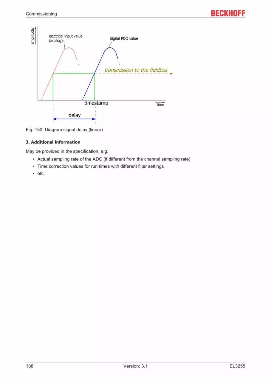
Commissioning
EL3255138 Version: 3.1
Fig. 150: Diagram signal delay (linear)
3. Additional Information
May be provided in the specification, e.g.
• Actual sampling rate of the ADC (if different from the channel sampling rate)• Time correction values for run times with different filter settings• etc.

Commissioning
EL3255 139Version: 3.1
5.6.9 Explanation of the term GND/GroundI/O devices always have a reference potential somewhere. After all, the working voltage is only created bytwo points having different potentials – one of these points is then called the reference potential.
In the Beckhoff I/O area and in particular with the analog products, various reference potentials are used andnamed. These are defined, named and explained here.
Note: for historical reasons, different names are used with various Beckhoff I/O products. The followingexplanations place them on a uniform foundation.
SGND• Also called: FE, Functional Earth, Shield GND, Shield.• Use: Dissipation of interference and radiation, predominantly currentless.
• Symbol: .• Notes and recommendations on SGND/FE can be found in the separate chapter
Notes regarding analog equipment - shielding and earth.• SGND usually ends at the structural earth star point.• In order to be usable for its intended purpose, SGND itself should be a low noise/noise-free "clean"
current and voltage sink.
PE• Also called: Protective Earth.• Use: Protective measure to prevent the occurrence of hazardous touch voltages by dissipating these
touch voltages and then tripping upstream protective devices. If installed correctly, the PE conductor iscurrentless, but according to specification it must be capable of conducting for the protection case.
• Symbol: .• PE usually ends at the structural earth star point.• For specifications and notes on PE, please refer to the relevant rules.
PGND, AGND• Use: Reference ground or return line of analog or digital signals.• Depending on use, nominally currentless as reference potential or conducting as return line.• In the analog area, the so-called standard signals can be 0...10 V and 4...20 mA, measuring bridge
signals and thermocouples can be in the range of a few mV and resistance measurement in any Ohmrange, and voltages can be from µV to a few thousand Volts.
• In the digital area they can be, for example, 0/24 V, -5/+5 V etc.• Symbols:
preferred: ;
hardly used any more, but actually means earth potential: .• There may be several PGND/AGND networks in a system that are electrically isolated from one
another.• If a device has several AGNDs, due to isolation by channel, these can be numbered: AGND1, AGND2,
…• PGND
◦ also called: GNDPC, 0 V, power contact 0 V, GND.◦ Version: PGND is a structural description of the "negative" power contact rail of the Bus Terminal
system.

Commissioning
EL3255140 Version: 3.1
◦ Can be connected to the device electronics, for example for supplying power to the device or as asignal feedback (see chapter Ground reference: single-ended/differential typification [} 129]).Refer to the respective device documentation.
◦ Example: PGND is not connected to the device electronics:
.• AGND
◦ Also called: GNDint, GND, analog ground, GNDanalog.◦ AGND electrically designates the device's analog reference ground.◦ AGND can, for example, be internally connected to PGND or to a connection point so that it can
be connected externally to a desired potential. Electrical restrictions according to the devicedocumentation must be observed, e.g. common mode limits.
◦ AGND is usually a currentless reference potential. The action of interference on AGND must beavoided.
◦ Example: AGND is fed out on the device plug:
.

Commissioning
EL3255 141Version: 3.1
5.6.10 Sampling type: Simultaneous vs. multiplexedAnalog inputs and outputs in Beckhoff devices can operate in 2 different ways in terms of time:"simultaneous sampling" or "multiplex sampling". This so-called sampling type has a decisive influence onthe performance of such a device and must be taken into consideration when selecting a product, at leastwhen it comes to very complex timing control tasks. Whether an analog device operates simultaneously ormultiplexed can be taken from the respective device documentation.
This question is relevant for control tasks as well as for measurement tasks (DataRecording), if the timing ofthe analog value acquisition is sensitive.
Note: The terms "simultaneous" and "multiplex" have been used for a long time and in many contexts, sothey have different meanings depending on the historical background and the subject area. In this chapterand in relation to I/O, the terms are used as Beckhoff understands them as an I/O manufacturer for thebenefit of the user:
• If a test signal is applied electrically to all channels of a multi-channel device at the same time and themeasurements are evaluated in software, e.g. in TwinCAT Scope, and if no significant offset/delay canbe observed between the channels, then it is a simultaneously sampling device *)
• If an offset can be seen, it is a multiplex sampling device• The easiest test to perform is with a square wave signal because an offset can then be easily
observed. However, the rare special case could occur (especially if the test signal is generated from anEL2xxx/EL4xxx from the same IO line) that the square wave signal runs synchronously to theEtherCAT for several minutes and then no offset can be seen.
Absolutely safe is a test with a sinusoidal signal, but then it must be considered that measurement deviations(related to the amplitude) of the channels in the device are also represented as time offset!
Ideally, one should concentrate on the zero crossing.
• 1-channel devices are considered as simultaneous sampling by definition.
Explanation with the example "analog input": if a continuous analog signal is to be digitized and thus fed tothe further programmatic processing, it is digitized by a so-called ADC (AnalogDigitalConverter), e.g. with 16bit resolution:
Fig. 151: Schematic representation of sampling with ADC converter
This represents an analog input channel that is functional in itself. It samples (measures) as often as desired,e.g. 1,000 times per second, and thus sends 1,000 measured values equidistant in time (= at equal timeintervals) for further processing.
Often several channels are combined in one device, in this case the question arises about the sampling type:simultaneous or multiplex.
*) For experts: such a device could also be equipped with a multiplexing ADC, which works with sample-and-hold on all channels. Then technically multiplex is built in, but from the outside the device workssimultaneously, because all channels are electrically read in at the same time.
Simultaneous
As in the 1-channel example, each channel can have its own ADC, shown here for 4 channels:
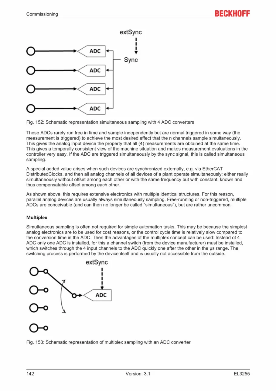
Commissioning
EL3255142 Version: 3.1
Fig. 152: Schematic representation simultaneous sampling with 4 ADC converters
These ADCs rarely run free in time and sample independently but are normal triggered in some way (themeasurement is triggered) to achieve the most desired effect that the n channels sample simultaneously.This gives the analog input device the property that all (4) measurements are obtained at the same time.This gives a temporally consistent view of the machine situation and makes measurement evaluations in thecontroller very easy. If the ADC are triggered simultaneously by the sync signal, this is called simultaneoussampling.
A special added value arises when such devices are synchronized externally, e.g. via EtherCATDistributedClocks, and then all analog channels of all devices of a plant operate simultaneously: either reallysimultaneously without offset among each other or with the same frequency but with constant, known andthus compensatable offset among each other.
As shown above, this requires extensive electronics with multiple identical structures. For this reason,parallel analog devices are usually always simultaneously sampling. Free-running or non-triggered, multipleADCs are conceivable (and can then no longer be called "simultaneous"), but are rather uncommon.
Multiplex
Simultaneous sampling is often not required for simple automation tasks. This may be because the simplestanalog electronics are to be used for cost reasons, or the control cycle time is relatively slow compared tothe conversion time in the ADC. Then the advantages of the multiplex concept can be used: Instead of 4ADC only one ADC is installed, for this a channel switch (from the device manufacturer) must be installed,which switches through the 4 input channels to the ADC quickly one after the other in the µs range. Theswitching process is performed by the device itself and is usually not accessible from the outside.
Fig. 153: Schematic representation of multiplex sampling with an ADC converter

Commissioning
EL3255 143Version: 3.1
This is therefore a time multiplex. As a rule the ADC samples equally clocked, the time intervals of thechannels are therefore equal, whereby the start of channel 1 is usually done by the communication cycle(EtherCAT) or DistributedClocks. For further details please refer to the device documentation.
Advantage: cheaper electronics compared to simultaneous setup.
Disadvantage: the measured values are no longer acquired simultaneously, but one after the other.
Both circuits have their technical and economic justification, for time demanding automation taskssimultaneous circuits should always be chosen, because with them it is easier to keep the temporaloverview.
For analog outputs the same explanations apply, they can also be equipped with multiple simultaneousDACs or output a multiplexed DAC to several outputs.

Commissioning
EL3255144 Version: 3.1
5.7 Process data and operating modes
5.7.1 Basic function principlesSome aspects and settings of the EL3255 are described in greater detail below.
5.7.1.1 General notes
The EL3255 operates as potentiometer evaluation terminal with ratiometric measurement. The connectedpotentiometers are supplied via the internal power supply unit. An external supply is not permissible andapplicable.
5.7.1.2 No. of channels
In the standard setting the EL3255 has 5 activated equivalent channels. 4 - 1 channels can be activated bythe process data selection. According to the notes below the terminal conversion time may be shortened.It may be useful to reduce the number of channels if fewer than 5 potentiometers are connected and theError LEDs that would be lit accordingly would disturb the appearance.
5.7.1.3 Process data flow
The internal data flow of the EL3255 indicates the order of the mathematical operation on the measuredvalue:
Fig. 154: Data flow of the EL3255
Sequence:
1. Raw value query from the ADC, simultaneous sampling of all channels after trigger setting (DC/syn-chron)
2. Check underrange/overrange3. Linearization correction according to the potentiometer specification4. Filtering5. Manufacturer and/or user calibration6. Limit evaluation7. Display of Siemens bits
Overrange evaluation
The measured value is checked for overrange taking into account the calibration settings.

Commissioning
EL3255 145Version: 3.1
Fig. 155: Error and overrange check
5.7.1.4 Operating modes
The EL3255 supports three different operating modes:
• Freerun (filter on, timer interrupt)• Synchron (filter off, SyncManager interrupt)• Distributed-Clock-triggered (DC-Sync interrupt)
The operating mode required for the application is to be selected according to the following decision tree:

Commissioning
EL3255146 Version: 3.1
Fig. 156: Operating modes of the EL3255
The terminal switches between the Freerun (filter on) and Synchron modes by activating/deactivating thefilter via the index. The terminal remains in OP mode during this process. The changeover may result inlonger sampling times and step changes in the process data until the filters have assumed a steady state.
DC mode can only be used when the filters are switched off. Likewise, it is not possible to switch the filterson in DC mode. The DC mode is parameterized via the DC tab in the TwinCAT System Manager.
Synchronous operation
In synchronous operation process data are generated frame-triggered, so that a new value is available witheach PLC cycle. Synchronous operation is automatically used if the filters are deactivated and no DC isactivated.
The minimum permissible cycle times are 500 µs in 5-channel mode and 300 µs in 2-channel mode.
DC operation
In DC mode the process data are requested via DC interrupt. As a result the temporal jitter between twoframes is compensated and the sampling time is the same across the entire system, even over manyEtherCAT devices.
The DC mode requires minimum cycle times of 500 µs in 5-channel mode and 300 µs in 2-channel mode.The "Input-based" mode automatically shifts the sync interrupt in such a way that the process data are readyshortly before the current process data cycle, therefore it is recommended as the standard setting forDCmode.
The measured value is typically read 500 ± 200 ns after the SYNC1 interrupt. There must be a temporal gapof 20 µs between SYNC0 and SYNC1.

Commissioning
EL3255 147Version: 3.1
Filter operation (FIR and IIR), Index 0x80n0:06 [} 158], 0x80n0:15 [} 158]
The EL3255 is equipped with a digital filter which, depending on its settings, can adopt the characteristics ofa Finite Impulse Response filter (FIR filter), or an Infinite Impulse Response filter (IIR filter). The filter isdeactivated by default. Please observe the following note regarding activation with index 0x8000:06 [} 158].
Activation of the filter with index 0x8000:06 [} 158] and setting of the filter charac-teristics via index 0x8000:15 [} 158]The filter frequencies are set for all channels of the EL3255 centrally via index 0x8000:15 [} 158](channel 1). The corresponding indices 80n0:15 of the other channels have no parameterizationfunction.
FIR filter
The filter performs a notch filter function and determines the conversion time of the terminal. It isparameterized via the index 0x8000:15 [} 158]. The higher the filter frequency, the faster the conversion time.A 50 Hz and a 60 Hz filter are available.Notch filter means that the filter has zeros (notches) in the frequency response at the filter frequency andmultiples thereof, i.e. it attenuates the amplitude at these frequencies.
The FIR filter operates as a non-recursive filter.
Fig. 157: Typical attenuation curve of notch filter at 50Hz
Filter data for FIR filterFilter Attenuation Limit frequency (-3 dB) typ. conversion time50 Hz FIR > 50 dB 22 Hz 625 µs60 Hz FIR > 45 dB 26 Hz 521 µs
IIR filter
The filter with IIR characteristics is a discrete time, linear, time invariant filter that can be set to eight levels(level 1 = weak recursive filter, up to level 8 = strong recursive filter).The IIR can be understood to be a moving average value calculation after a low-pass filter.
Due to the FreeRun synchronization mode, the IIR filter operates with an internal cycle time of approx. 500µs.

Commissioning
EL3255148 Version: 3.1
IIR filter Limit frequency (-3 dB), 5 activated channelsIIR 1 400 HzIIR 2 220 HzIIR 3 100 HzIIR 4 50 HzIIR 5 24 HzIIR 6 12 HzIIR 7 6.2 HzIIR 8 3.0 Hz
5.7.1.5 Limit evaluation, index 80n0:07/08
If the value exceeds or falls below these values, which can be entered in the indices 0x80n0:13 [} 158] and0x80n0:14 [} 158], then the bits in the indices 0x60n0:03 [} 159] and 0x60n0:05 [} 159]are set accordingly.The indices 0x80n0:07 [} 158] or 0x80n0:08 [} 158] serve to activate the limit value monitoring. The limitfunction can be inverted by SwapLimitBits in index 0x80n0:0E [} 158].
Output Limit n (2-bit):
SwapLimitBits setting ValueTRUE (default setting) • 0: not active
• 1: value > limit value• 2: value < limit value• 3: Value is equal to the limit value
FALSE • 0: not active• 1: value < limit value• 2: value > limit value• 3: Value is equal to the limit value
Note on linking in the PLC with 2-bit values
Linking in the PLC with 2-bit valuesThe limit information consists of 2 bits. Limitn can be linked to the PLC or a task in the System Man-ager.
• PLC:IEC61131-PLC contains no 2-bit data type that can be linked with this process data directly. Fortransferring the limit information, define an input byte (e.g. see Fig. Input byte definition) and link thelimit to the VariableSizeMismatch dialog, as described in section Note about the 1-byte status of earlierEtherCAT Terminals.
Fig. 158: Input byte definition
• Additional task2-bit variables can be created in the System Manager.

Commissioning
EL3255 149Version: 3.1
Fig. 159: Linking of 2-bit variable to additional task
Channel 1; Limit 1 and Limit 2 enabled, Limit 1 = 5000 (corresponding to ~15% control), Limit 2 = 15000(corresponding to ~45%)
Input channel 1 Index 0x6000:03 [} 159] Index 0x6000:05 [} 159]4500 0x02hex, (Limit 1, limit value undershot) 0x02hex, (Limit 2, limit value undershot)5000 0x03hex, (Limit 1, limit value reached) 0x02hex, (Limit 2, limit value undershot)
5.7.1.6 Siemens bits, index 80n0:05
If this bit is set, status displays are superimposed on the lowest three bits in the status word. In the errorcase "overrange" or "underrange", bit 0 is set.

Commissioning
EL3255150 Version: 3.1
5.7.2 Application notes
Note on open-circuit recognition from firmware 04 [} 180]• The open-circuit recognition runs acyclically in the background.• The open-circuit recognition for the potentiometer wiper takes place every 3 cycles, if the
value 10k (0) is entered in all 0x80n0:1C [} 158] objects (on all channels). In this case the open-circuit recognition is particularly fast. If a >20 kOhm potentiometer is nevertheless connected toone of the channels, a broken wire message may occur, even if no broken wire is present.Therefore, the nearest suitable value that matches the connected potentiometer should be set in0x80n0:1C [} 158].
• The open-circuit recognition for the wiper is slower, if at least for one channel a value >10k ( > 0)has been entered.
Diagnostic options
The diagnostic functions of the terminal can be set via the CoE object 0x8047:11 [} 158]. The settings apply to all channels together:
Fig. 160: Set Value Dialog, diagnostic options
• Sensor Monitoring: Wiper wire break detection• Load Monitoring: Monitoring of the potentiometer supply lines• Supply monitoring: Monitoring of the 24V supply via the power contacts, potentiometer overload/short
circuit
It is recommended to use the full diagnostic scope if possible. If the terminal detects an error, Value=0 andError=1 are reported.
In some cases it can happen that potentiometer wipers lose contact with the contact surface duringmovement, especially at higher speeds or increasing aging. In this case the wiper wire break detection canbe switched off to avoid false alarms. Wiper wire break detection is performed by cyclic voltage pulses. Thepulses can be measured from the outside (if the wiper is not grounded), but are not included in themeasurement result of the channel.

Commissioning
EL3255 151Version: 3.1
Further characteristics
Feature ExplanationPotentiometer The potentiometers connected to channels 1 - 5 do not have to be of the same type or
resistance value.Power dissipation Significant portions of power are converted into heat in the connected potentiometers.
Due to the terminal feed of typically 10 V, approx. 0.3 W are converted in a 300 Ωpotentiometer.
Diagnostics The Error LED or the status word indicates• broken wire in one of the three potentiometer supply cables• short-circuit on the potentiometer supply (shunt)A shunt between the wiper conductor and one end of the potentiometer feed cannotbe recognized. See "Note on open-circuit recognition from firmware 04 [} 150]"
Compensation ofsupply cableresistances
In the case of very long cable lengths with small cross-sections the line resistances Aand C can limit the measuring range. This error can be corrected with the "usercalibration" function: To do this, activate the IIR 8 filter and the "Enable usercalibration" function. Set the potentiometer to the lower limit and enter the input valuein "User calibration offset". Then set the potentiometer to the upper limit and calculatethe "User calibration gain": Y = 32768/X*16384.
Error Codes
Error Underrange Overrange Datainvalid
TxPDOState
SyncError
Error description Remedy
1 1 Measurement isbelow range
Reduce the input level,change the gain (filtersettings)
1 1 Measuring rangeexceeded
Reduce the input level,change the gain (filtersettings)
1 General measuringerror
e.g. broken wire or shortcircuit
1 Synchronization error Master jitter too high, DCswitched off
1 Internal data error Check data transmission 1 Internal data error Check data transmission
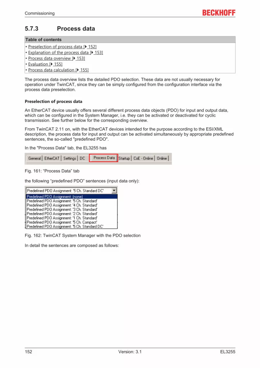
Commissioning
EL3255152 Version: 3.1
5.7.3 Process dataTable of contents• Preselection of process data [} 152]• Explanation of the process data [} 153]• Process data overview [} 153]• Evaluation [} 155]• Process data calculation [} 155]
The process data overview lists the detailed PDO selection. These data are not usually necessary foroperation under TwinCAT, since they can be simply configured from the configuration interface via theprocess data preselection.
Preselection of process data
An EtherCAT device usually offers several different process data objects (PDO) for input and output data,which can be configured in the System Manager, i.e. they can be activated or deactivated for cyclictransmission. See further below for the corresponding overview.
From TwinCAT 2.11 on, with the EtherCAT devices intended for the purpose according to the ESI/XMLdescription, the process data for input and output can be activated simultaneously by appropriate predefinedsentences, the so-called "predefined PDO".
In the "Process Data" tab, the EL3255 has
Fig. 161: “Process Data” tab
the following “predefined PDO” sentences (input data only):
Fig. 162: TwinCAT System Manager with the PDO selection
In detail the sentences are composed as follows:

Commissioning
EL3255 153Version: 3.1
Operating mode Name SM2, PDO assignment SM3, PDO assignmentSM-synchron “frame-triggered”
5 Ch. Standard (defaultsetting)
- 0x1A000x1A020x1A040x1A060x1A08
4 Ch. Standard - 0x1A000x1A020x1A040x1A06
3 Ch. Standard - 0x1A000x1A020x1A04
2 Ch. Standard - 0x1A000x1A02
1 Ch. Standard - 0x1A005 Ch. Compact - 0x1A01
0x1A030x1A050x1A070x1A09
DC-synchron 5 Ch. Standard - 0x1A000x1A020x1A040x1A060x1A08
Explanation of the process data
The default process image (5 Ch. Standard) encompasses the following data:
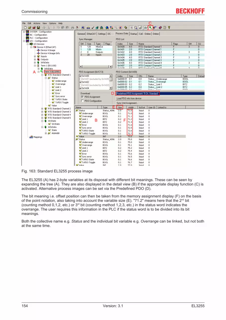
Commissioning
EL3255154 Version: 3.1
Fig. 163: Standard EL3255 process image
The EL3255 (A) has 2-byte variables at its disposal with different bit meanings. These can be seen byexpanding the tree (A). They are also displayed in the detail view (B) if the appropriate display function (C) isactivated. Alternative process images can be set via the Predefined PDO (D).
The bit meaning i.e. offset position can then be taken from the memory assignment display (F) on the basisof the point notation, also taking into account the variable size (E). "71.2" means here that the 2nd bit(counting method 0,1,2, etc.) or 3rd bit (counting method 1,2,3, etc.) in the status word indicates theoverrange. The user requires this information in the PLC if the status word is to be divided into its bitmeanings.
Both the collective name e.g. Status and the individual bit variable e.g. Overrange can be linked, but not bothat the same time.

Commissioning
EL3255 155Version: 3.1
Input dataCollectivename
Name Description / function Bit position [0 -15]
Status Underrange Indicates that the electrical measuring range isundershot
0
Overrange Indicates that the electrical measuring range isexceeded
1
Limit 1 Evaluation limit 1
Setting according to CoE object 0x80n0:07 [} 158], seealso Notes [} 148]
2
Limit 2 Evaluation limit 2, setting based on CoE object0x80n0:08 [} 158], see also Notes [} 148]
4
Error An error has occurred,Error Codes [} 150]
66
Sync error Signals a synchronization error if “distributed clocks”are activated.
13
TxPDO State Validity of the process data, TRUE means invalidprocess data on this channel
14
TxPDOToggle
Changes its state 0/1 each time process data areexchanged.
15
Value 16-bit measured value 0 - x7FFFWcState Setpoint during operation: 0
Each datagram of the EL3255 indicates its processingstate here. This allows the EL3255 to be monitored forcorrect process data communication.
InfoData (State) Setpoint during operation: 8Status display of the “EtherCAT state machine”
AdsAddr AMS address of the responsible EtherCAT Master inthe format "0.0.0.0.0.0". In addition, the port numbervalid for this Slave.Required for acyclic accesses to the CoE at runtime.
Evaluation
For the regular operation of the EL3255 (as for every analog input terminal), proceed as follows via thediagnostic depth:
• Fieldbus/EtherCAT◦ cyclic control of DevState
• Device/EL3255◦ cyclic control of State, WcState
• Channel x◦ cyclic control of Error, TxPDoState, SyncError (in case of DC operation)
If the "EL3255" device diagnostics signals no communication, then the subordinate "Channel" level is also nolonger to be considered ready for operation.
Calculation of process data
The concept “calibration”, which has historical roots at Beckhoff, is used here even if it has nothing to do withthe deviation statements of a calibration certificate. Actually, this is a description of the vendor or customercalibration data/adjustment data used by the device during operation in order to maintain the assuredmeasuring accuracy.

Commissioning
EL3255156 Version: 3.1
The terminal constantly records measured values and saves the raw values from its A/D converter in theADC raw value object 0x80nE:01. After each recording of the analog signal, the correction calculation takesplace with the vendor and user calibration data as well as the user scaling, if these are activated (seefollowing picture).
Fig. 164: Calculation of process data
Calculation DesignationXADC Output of the A/D converterXF Output value after the filterYH = (XADC – BH) x AH x 2-14 Measured value after vendor calibration,YA = (YH – BA) x AA x 2 -14
Measured value after vendor and user calibration
YS= YA x AS x 2-16 + BS Measured value following user scaling
Table 1: Legend
Name Designation IndexXADC Output value of the A/D converter 0x80nE:01XF Output value after the filter -BH Vendor calibration offset (not changeable) 0x80nF:01AH Vendor calibration gain (not changeable) 0x80nF:02BA User calibration offset (can be activated via index 0x80n0:0A) 0x80n0:17AA User calibration gain (can be activated via index 0x80n0:0A) 0x80n0:18BS User scaling offset (can be activated via index 0x80n0:01) 0x80n0:11AS User scaling gain (can be activated via index 0x80n0:01) 0x80n0:12YS Process data for controller -
Measurement resultThe accuracy of the result may be reduced if the measured value is smaller than 32767 / 4 due toone or more multiplications.

Commissioning
EL3255 157Version: 3.1
5.7.4 Object description and parameterizationThe filter properties are set only via index 0x8000:15The filter frequencies are set for all channels of the EL3255 terminals centrally via index 0x8000:15(channel 1).
EtherCAT XML Device DescriptionThe display matches that of the CoE objects from the EtherCAT XML Device Description. We rec-ommend downloading the latest XML file from the download area of the Beckhoff website and in-stalling it according to installation instructions.
Parameterization via the CoE list (CAN over EtherCAT)The terminal is parameterized via the CoE - Online tab (double-click on the respective object) or viathe Process Data tab (allocation of PDOs). Please note the following general CoE information whenusing/manipulating the CoE parameters: - Keep a startup list if components have to be replaced -Differentiation between online/offline dictionary, existence of current XML description - Use "CoEreload" for resetting changes
5.7.4.1 Restore object
Index 1011 Restore default parametersIndex (hex) Name Meaning Data type Flags Default1011:0 Restore default param-
eters [} 181]Restore default parameters UINT8 RO 0x01 (1dec)
1011:01 SubIndex 001 If this object is set to “0x64616F6C” in the set value di-alog, all backup objects are reset to their delivery state.
UINT32 RW 0x00000000(0dec)

Commissioning
EL3255158 Version: 3.1
5.7.4.2 Configuration data
Index 80n0 AI SettingsIndex(hex)
Name Meaning Data type Flags Default
80n0:0 RTD Settings Ch.1 Maximum subindex UINT8 RO 0x1C (28dec)80n0:01 Enable user scale User scale is active. BOOLEAN RW 0x00 (0dec)80n0:05 Siemens bits The S5 bits are displayed in the three low-order bits BOOLEAN RW 0x00 (0dec)80n0:06 Enable filter Enable filter, which makes PLC-cycle-synchronous
data exchange unnecessaryBOOLEAN RW 0x00 (0dec)
80n0:07 Enable limit 1 The status bits are set in relation to Limit 1 BOOLEAN RW 0x00 (0dec)80n0:08 Enable limit 2 The status bits are set in relation to Limit 2 BOOLEAN RW 0x00 (0dec)80n0:0A Enable user calibration Enabling of the user calibration BOOLEAN RW 0x00 (0dec)80n0:0B Enable vendor calibra-
tionEnabling of the vendor calibration BOOLEAN RW 0x01 (1dec)
80n0:0E Swap limit bits Swap limit bits BOOLEAN RW 0x01 (1dec)80n0:11 User scale offset User scaling offset INT16 RW 0x0000 (0dec)80n0:12 User scale gain This is the user scaling gain.
The gain is represented in fixed-point format, with thefactor 2-16.The value 1 corresponds to 65535 (0x00010000).
INT32 RW 0x00010000(65536dec)
80n0:13 Limit 1 First limit value for setting the status bits INT16 RW 0x0000 (0dec)80n0:14 Limit 2 Second limit value for setting the status bits INT16 RW 0x0000 (0dec)80n0:15 Filter settings This object determines the digital filter settings, if it is
active via Enable filter (index 0x8000:06 [} 158]).The possible settings are sequentially numbered (seenote below “The filter properties are set only via index0x8000:15”).
ENUM6 RW 50 Hz FIR (0dec)
0 50 Hz FIR1 60 Hz FIR2 IIR 1 (400 Hz)3 IIR 2 (220 Hz)4 IIR 3 (100 Hz)5 IIR 4 (50 Hz)6 IIR 5 (24 Hz)7 IIR 6 (12 Hz)8 IIR 7 (6.2 Hz)9 IIR 8 (3.0 Hz)
80n0:17 User calibration offset User calibration offset INT16 RW 0x0000 (0dec)80n0:18 User calibration gain User calibration gain UINT16 RW 0xFFFF
(65535dec)80n0:1C Load resistance Linearization for potentiometer values >= 25 kOhm:
0 = off (up to 10 kOhm),1 = 25 kOhm,2 = 50 kOhm
ENUM16 RW 0x0000 (0dec)
The filter properties are set only via index 0x8000:15 [} 158]The filter frequencies are set for all channels of the EL3255 terminals centrally via index 0x8000:15[} 158] (channel 1).
Index 8047 AI Device SettingsIndex (hex) Name Meaning Data type Flags Default8047:0 AI Device Settings Max. subindex UINT8 RO 0x0B (11dec)8047:11 Wire breakage detec-
tion0: sensor/load/supply monitoring1: load/supply monitoring2: supply monitoring3: off
ENUM16 RW 0x0000 (0dec)

Commissioning
EL3255 159Version: 3.1
5.7.4.3 Input data
Index 60n0 AI Inputs (for 0 ≤ n ≤ 4; channel 1 - 5)Index (hex) Name Meaning Data type Flags Default60n0:0 AI Inputs Max. Subindex UINT8 RO 0x11 (17dec)60n0:01 Underrange The measuring range is undershot. BOOLEAN RO 0x00 (0dec)60n0:02 Overrange The measured value has reached its end value BOOLEAN RO 0x00 (0dec)60n0:03 Limit 1 Limit value monitoring
0: not active1: Value is larger than the limit value2: Value is smaller than the limit value3: Value is equal to the limit value
BIT2 RO 0x00 (0dec)
60n0:05 Limit 2 Limit value monitoring
0: not active1: Value is larger than the limit value2: Value is smaller than the limit value3: Value is equal to the limit value
BIT2 RO 0x00 (0dec)
60n0:07 Error An error has occurred. BOOLEAN RO 0x00 (0dec)60n0:0E Sync error The Sync error bit is only required for Distributed
Clocks mode. It indicates whether a synchronizationerror has occurred during the previous cycle.
BOOLEAN RO 0x00 (0dec)
60n0:0F TxPDO State Validity of the data of the associated TxPDO (0 = valid,1 = invalid).
BOOLEAN RO 0x00 (0dec)
60n0:10 TxPDO Toggle The TxPDO toggle is toggled by the slave when thedata of the associated TxPDO is updated.
BOOLEAN RO 0x00 (0dec)
60n0:11 Value Measured value as 32 bit signed integer INT32 RO 0x00000000(0dec)
5.7.4.4 Information / diagnosis data
Index 80nE AI Internal data (for 0 ≤ n ≤ 4; channel 1 - 5)Index (hex) Name Meaning Data type Flags Default80nE:0 AI Internal data Max. Subindex UINT8 RO 0x01 (1dec)80nE:01 ADC raw value 1 ADC raw value INT32 RO 0x00000000
(0dec)
5.7.4.5 Manufacturer configuration data
Index 80nE AI Vendor data (for 0 ≤ n ≤ 4; channel 1 - 5)Index (hex) Name Meaning Data type Flags Default80nF:0 AI Vendor data Max. Subindex UINT8 RO 0x02 (2dec)80nF:01 Calibration offset Offset (vendor calibration) INT32 RW 0x00000000
(0dec)80nF:02 Calibration gain Gain (vendor calibration) INT16 RW 0x4000
(16384dec)
5.7.4.6 Standard objects
Index 1000 Device typeIndex (hex) Name Meaning Data type Flags Default1000:0 Device type Device type of the EtherCAT slave: the Lo-Word con-
tains the CoE profile used (5001). The Hi-Word con-tains the module profile according to the modular de-vice profile.
UINT32 RO 0x012C1389(19665801dec)

Commissioning
EL3255160 Version: 3.1
Index 1008 Device nameIndex (hex) Name Meaning Data type Flags Default1008:0 Device name Device name of the EtherCAT slave STRING RO EL3255
Index 1009 Hardware versionIndex (hex) Name Meaning Data type Flags Default1009:0 Hardware version Hardware version of the EtherCAT slave STRING RO 00
Index 100A Software versionIndex (hex) Name Meaning Data type Flags Default100A:0 Software version Firmware version of the EtherCAT slave STRING RO 99-b0
Index 1018 IdentityIndex (hex) Name Meaning Data type Flags Default1018:0 Identity Information for identifying the slave UINT8 RO 0x04 (4dec)1018:01 Vendor ID Vendor ID of the EtherCAT slave UINT32 RO 0x00000002
(2dec)1018:02 Product code Product code of the EtherCAT slave UINT32 RO 0x0CB73052
(213332050dec)1018:03 Revision Revision number of the EtherCAT slave; the low word
(bit 0-15) indicates the special terminal number, thehigh word (bit 16-31) refers to the device description
UINT32 RO 0x00120000(1179648dec)
1018:04 Serial number Serial number of the EtherCAT slave; the low byte (bit0-7) of the low word contains the year of production,the high byte (bit 8-15) of the low word contains theweek of production, the high word (bit 16-31) is 0
UINT32 RO 0x00000000(0dec)
Index 10F0 Backup parameter handlingIndex (hex) Name Meaning Data type Flags Default10F0:0 Backup parameter
handlingInformation for standardised loading and saving ofbackup entries
UINT8 RO 0x01 (1dec)
10F0:01 Checksum Checksum across all backup entries of the EtherCATslave
UINT32 RO 0x00000000(0dec)
Index 1800 AI TxPDO-Par Standard Ch.1Index (hex) Name Meaning Data type Flags Default1800:0 AI TxPDO-Par Stan-
dard Ch.1PDO parameter TxPDO 1 UINT8 RO 0x09 (9dec)
1800:06 Exclude TxPDOs Specifies the TxPDOs (index of TxPDO mapping ob-jects) that must not be transferred together with Tx-PDO 1
OCTET-STRING[2]
RO 01 1A
1800:07 TxPDO State The TxPDO state is set if it was not possible to cor-rectly read in the associated input data
BOOLEAN RO 0x00 (0dec)
1800:09 TxPDO Toggle The TxPDO toggle is toggled with each update the cor-responding input data
BOOLEAN RO 0x00 (0dec)
Index 1801 AI TxPDO-Par Compact Ch.1Index (hex) Name Meaning Data type Flags Default1801:0 AI TxPDO-Par Com-
pact Ch.1PDO parameter TxPDO 2 UINT8 RO 0x06 (6dec)
1801:06 Exclude TxPDOs Specifies the TxPDOs (index of TxPDO mapping ob-jects) that must not be transferred together with Tx-PDO 2
OCTET-STRING[2]
RO 00 1A

Commissioning
EL3255 161Version: 3.1
Index 1802 AI TxPDO-Par Standard Ch.2Index (hex) Name Meaning Data type Flags Default1802:0 AI TxPDO-Par Stan-
dard Ch.2PDO parameter TxPDO 3 UINT8 RO 0x09 (9dec)
1802:06 Exclude TxPDOs Specifies the TxPDOs (index of TxPDO mapping ob-jects) that must not be transferred together with Tx-PDO 3
OCTET-STRING[2]
RO 03 1A
1802:07 TxPDO State The TxPDO state is set if it was not possible to cor-rectly read in the associated input data
BOOLEAN RO 0x00 (0dec)
1802:09 TxPDO Toggle The TxPDO toggle is toggled with each update the cor-responding input data
BOOLEAN RO 0x00 (0dec)
Index 1803 AI TxPDO-Par Compact Ch.2Index (hex) Name Meaning Data type Flags Default1803:0 AI TxPDO-Par Com-
pact Ch.2PDO parameter TxPDO 4 UINT8 RO 0x06 (6dec)
1803:06 Exclude TxPDOs Specifies the TxPDOs (index of TxPDO mapping ob-jects) that must not be transferred together with Tx-PDO 4
OCTET-STRING[2]
RO 02 1A
Index 1804 AI TxPDO-Par Standard Ch.3Index (hex) Name Meaning Data type Flags Default1804:0 AI TxPDO-Par Stan-
dard Ch.3PDO parameter TxPDO 5 UINT8 RO 0x09 (9dec)
1804:06 Exclude TxPDOs Specifies the TxPDOs (index of TxPDO mapping ob-jects) that must not be transferred together with Tx-PDO 5
OCTET-STRING[2]
RO 05 1A
1804:07 TxPDO State The TxPDO state is set if it was not possible to cor-rectly read in the associated input data
BOOLEAN RO 0x00 (0dec)
1804:09 TxPDO Toggle The TxPDO toggle is toggled with each update the cor-responding input data
BOOLEAN RO 0x00 (0dec)
Index 1805 AI TxPDO-Par Compact Ch.3Index (hex) Name Meaning Data type Flags Default1805:0 AI TxPDO-Par Com-
pact Ch.3PDO parameter TxPDO 6 UINT8 RO 0x06 (6dec)
1805:06 Exclude TxPDOs Specifies the TxPDOs (index of TxPDO mapping ob-jects) that must not be transferred together with Tx-PDO 6
OCTET-STRING[2]
RO 04 1A
Index 1806 AI TxPDO-Par Standard Ch.4Index (hex) Name Meaning Data type Flags Default1806:0 AI TxPDO-Par Stan-
dard Ch.4PDO parameter TxPDO 7 UINT8 RO 0x09 (9dec)
1806:06 Exclude TxPDOs Specifies the TxPDOs (index of TxPDO mapping ob-jects) that must not be transferred together with Tx-PDO 7
OCTET-STRING[2]
RO 07 1A
1806:07 TxPDO State The TxPDO state is set if it was not possible to cor-rectly read in the associated input data
BOOLEAN RO 0x00 (0dec)
1806:09 TxPDO Toggle The TxPDO toggle is toggled with each update the cor-responding input data
BOOLEAN RO 0x00 (0dec)
Index 1807 AI TxPDO-Par Compact Ch.4Index (hex) Name Meaning Data type Flags Default1807:0 AI TxPDO-Par Com-
pact Ch.4PDO parameter TxPDO 8 UINT8 RO 0x06 (6dec)
1807:06 Exclude TxPDOs Specifies the TxPDOs (index of TxPDO mapping ob-jects) that must not be transferred together with Tx-PDO 8
OCTET-STRING[2]
RO 06 1A

Commissioning
EL3255162 Version: 3.1
Index 1808 AI TxPDO-Par Standard Ch.5Index (hex) Name Meaning Data type Flags Default1808:0 AI TxPDO-Par Stan-
dard Ch.5PDO parameter TxPDO 9 UINT8 RO 0x09 (9dec)
1808:06 Exclude TxPDOs Specifies the TxPDOs (index of TxPDO mapping ob-jects) that must not be transferred together with Tx-PDO 9
OCTET-STRING[2]
RO 09 1A
1808:07 TxPDO State The TxPDO state is set if it was not possible to cor-rectly read in the associated input data
BOOLEAN RO 0x00 (0dec)
1808:09 TxPDO Toggle The TxPDO toggle is toggled with each update the cor-responding input data
BOOLEAN RO 0x00 (0dec)
Index 1809 AI TxPDO-Par Compact Ch.5Index (hex) Name Meaning Data type Flags Default1809:0 AI TxPDO-Par Com-
pact Ch.5PDO parameter TxPDO 10 UINT8 RO 0x06 (6dec)
1809:06 Exclude TxPDOs Specifies the TxPDOs (index of TxPDO mapping ob-jects) that must not be transferred together with Tx-PDO 10
OCTET-STRING[2]
RO 08 1A
Index 1A00 AI TxPDO-Map Standard Ch.1Index (hex) Name Meaning Data type Flags Default1A00:0 AI TxPDO-Map Stan-
dard Ch.1PDO Mapping TxPDO 1 UINT8 RO 0x0B (11dec)
1A00:01 SubIndex 001 1. PDO Mapping entry (object 0x6000 (AI Inputs), entry0x01 (Underrange))
UINT32 RO 0x6000:01, 1
1A00:02 SubIndex 002 2. PDO Mapping entry (object 0x6000 (AI Inputs), entry0x02 (Overrange))
UINT32 RO 0x6000:02, 1
1A00:03 SubIndex 003 3. PDO Mapping entry (object 0x6000 (AI Inputs), entry0x03 (Limit 1))
UINT32 RO 0x6000:03, 2
1A00:04 SubIndex 004 4. PDO Mapping entry (object 0x6000 (AI Inputs), entry0x05 (Limit 2))
UINT32 RO 0x6000:05, 2
1A00:05 SubIndex 005 5. PDO Mapping entry (object 0x6000 (AI Inputs), entry0x07 (Error))
UINT32 RO 0x6000:07, 1
1A00:06 SubIndex 006 6. PDO Mapping entry (1 bits align) UINT32 RO 0x0000:00, 11A00:07 SubIndex 007 7. PDO Mapping entry (6 bits align) UINT32 RO 0x0000:00, 51A00:08 SubIndex 008 8. PDO Mapping entry (object 0x1800 (RTD TxPDO-
Par Standard Ch.1), entry 0x07 (TxPDO State))UINT32 RO 0x1C33:20, 1
1A00:09 SubIndex 009 9. PDO Mapping entry (object 0x1800 (RTD TxPDO-Par Standard Ch.1), entry 0x09 (TxPDO Toggle))
UINT32 RO 0x1800:07, 1
1A00:0A SubIndex 010 10. PDO Mapping entry (object 0x6000 (AI Inputs), en-try 0x11 (Value))
UINT32 RO 0x1800:09, 1
1A00:0B SubIndex 011 11. PDO Mapping entry (object 0x6000 (AI Inputs), en-try 0x11 (Value))
UINT32 RO 0x6000:11, 16
Index 1A01 AI TxPDO-Map Compact Ch.1Index (hex) Name Meaning Data type Flags Default1A01:0 AI TxPDO-Map Com-
pact Ch.1PDO Mapping TxPDO 2 UINT8 RO 0x01 (1dec)
1A01:01 SubIndex 001 1. PDO Mapping entry (object 0x6000 (AI Inputs), entry0x11 (Value))
UINT32 RO 0x6000:11, 16

Commissioning
EL3255 163Version: 3.1
Index 1A02 AI TxPDO-Map Standard Ch.2Index (hex) Name Meaning Data type Flags Default1A02:0 AI TxPDO-Map Stan-
dard Ch.2PDO Mapping TxPDO 3 UINT8 RO 0x0B (11dec)
1A02:01 SubIndex 001 1. PDO Mapping entry (object 0x6010 (AI Inputs), entry0x01 (Underrange))
UINT32 RO 0x6010:01, 1
1A02:02 SubIndex 002 2. PDO Mapping entry (object 0x6010 (AI Inputs), entry0x02 (Overrange))
UINT32 RO 0x6010:02, 1
1A02:03 SubIndex 003 3. PDO Mapping entry (object 0x6010 (AI Inputs), entry0x03 (Limit 1))
UINT32 RO 0x6010:03, 2
1A02:04 SubIndex 004 4. PDO Mapping entry (object 0x6010 (AI Inputs), entry0x05 (Limit 2))
UINT32 RO 0x6010:05, 2
1A02:05 SubIndex 005 5. PDO Mapping entry (object 0x6010 (AI Inputs), entry0x07 (Error))
UINT32 RO 0x6010:07, 1
1A02:06 SubIndex 006 6. PDO Mapping entry (1 bits align) UINT32 RO 0x0000:00, 11A02:07 SubIndex 007 7. PDO Mapping entry (6 bits align) UINT32 RO 0x0000:00, 51A02:08 SubIndex 008 8. PDO Mapping entry (object 0x1802 (RTD TxPDO-
Par Standard Ch.2), entry 0x07 (TxPDO State))UINT32 RO 0x1C33:20, 1
1A02:09 SubIndex 009 9. PDO Mapping entry (object 0x1802 (RTD TxPDO-Par Standard Ch.2), entry 0x09 (TxPDO Toggle))
UINT32 RO 0x1802:07, 1
1A02:0A SubIndex 010 10. PDO Mapping entry (object 0x6010 (AI Inputs), en-try 0x11 (Value))
UINT32 RO 0x1802:09, 1
1A02:0B SubIndex 011 11. PDO Mapping entry (object 0x6010 (AI Inputs), en-try 0x11 (Value))
UINT32 RO 0x6010:11, 16
Index 1A03 AI TxPDO-Map Compact Ch.2Index (hex) Name Meaning Data type Flags Default1A03:0 AI TxPDO-Map Com-
pact Ch.2PDO Mapping TxPDO 4 UINT8 RO 0x01 (1dec)
1A03:01 SubIndex 001 1. PDO Mapping entry (object 0x6010 (AI Inputs), entry0x11 (Value))
UINT32 RO 0x6010:11, 16
Index 1A04 AI TxPDO-Map Standard Ch.3Index (hex) Name Meaning Data type Flags Default1A04:0 AI TxPDO-Map Stan-
dard Ch.3PDO Mapping TxPDO 5 UINT8 RO 0x0B (11dec)
1A04:01 SubIndex 001 1. PDO Mapping entry (object 0x6020 (AI Inputs), entry0x01 (Underrange))
UINT32 RO 0x6020:01, 1
1A04:02 SubIndex 002 2. PDO Mapping entry (object 0x6020 (AI Inputs), entry0x02 (Overrange))
UINT32 RO 0x6020:02, 1
1A04:03 SubIndex 003 3. PDO Mapping entry (object 0x6020 (AI Inputs), entry0x03 (Limit 1))
UINT32 RO 0x6020:03, 2
1A04:04 SubIndex 004 4. PDO Mapping entry (object 0x6020 (AI Inputs), entry0x05 (Limit 2))
UINT32 RO 0x6020:05, 2
1A04:05 SubIndex 005 5. PDO Mapping entry (object 0x6020 (AI Inputs), entry0x07 (Error))
UINT32 RO 0x6020:07, 1
1A04:06 SubIndex 006 6. PDO Mapping entry (1 bits align) UINT32 RO 0x0000:00, 11A04:07 SubIndex 007 7. PDO Mapping entry (6 bits align) UINT32 RO 0x0000:00, 51A04:08 SubIndex 008 8. PDO Mapping entry (object 0x1804 (RTD TxPDO-
Par Standard Ch.3), entry 0x07 (TxPDO State))UINT32 RO 0x1C33:20, 1
1A04:09 SubIndex 009 9. PDO Mapping entry (object 0x1804 (RTD TxPDO-Par Standard Ch.3), entry 0x09 (TxPDO Toggle))
UINT32 RO 0x1804:07, 1
1A04:0A SubIndex 010 10. PDO Mapping entry (object 0x6020 (AI Inputs), en-try 0x11 (Value))
UINT32 RO 0x1804:09, 1
1A04:0B SubIndex 011 11. PDO Mapping entry (object 0x6020 (AI Inputs), en-try 0x11 (Value))
UINT32 RO 0x6020:11, 16

Commissioning
EL3255164 Version: 3.1
Index 1A05 AI TxPDO-Map Compact Ch.3Index (hex) Name Meaning Data type Flags Default1A05:0 AI TxPDO-Map Com-
pact Ch.3PDO Mapping TxPDO 6 UINT8 RO 0x01 (1dec)
1A05:01 SubIndex 001 1. PDO Mapping entry (object 0x6020 (AI Inputs), entry0x11 (Value))
UINT32 RO 0x6020:11, 16
Index 1A06 AI TxPDO-Map Standard Ch.4Index (hex) Name Meaning Data type Flags Default1A06:0 AI TxPDO-Map Stan-
dard Ch.4PDO Mapping TxPDO 7 UINT8 RO 0x0B (11dec)
1A06:01 SubIndex 001 1. PDO Mapping entry (object 0x6030 (AI Inputs), entry0x01 (Underrange))
UINT32 RO 0x6030:01, 1
1A06:02 SubIndex 002 2. PDO Mapping entry (object 0x6030 (AI Inputs), entry0x02 (Overrange))
UINT32 RO 0x6030:02, 1
1A06:03 SubIndex 003 3. PDO Mapping entry (object 0x6030 (AI Inputs), entry0x03 (Limit 1))
UINT32 RO 0x6030:03, 2
1A06:04 SubIndex 004 4. PDO Mapping entry (object 0x6030 (AI Inputs), entry0x05 (Limit 2))
UINT32 RO 0x6030:05, 2
1A06:05 SubIndex 005 5. PDO Mapping entry (object 0x6030 (AI Inputs), entry0x07 (Error))
UINT32 RO 0x6030:07, 1
1A06:06 SubIndex 006 6. PDO Mapping entry (1 bits align) UINT32 RO 0x0000:00, 11A06:07 SubIndex 007 7. PDO Mapping entry (6 bits align) UINT32 RO 0x0000:00, 51A06:08 SubIndex 008 8. PDO Mapping entry (object 0x1806 (RTD TxPDO-
Par Standard Ch.4), entry 0x07 (TxPDO State))UINT32 RO 0x1C33:20, 1
1A06:09 SubIndex 009 9. PDO Mapping entry (object 0x1806 (RTD TxPDO-Par Standard Ch.4), entry 0x09 (TxPDO Toggle))
UINT32 RO 0x1806:07, 1
1A06:0A SubIndex 010 10. PDO Mapping entry (object 0x6030 (AI Inputs), en-try 0x11 (Value))
UINT32 RO 0x1806:09, 1
1A06:0B SubIndex 011 11. PDO Mapping entry (object 0x6030 (AI Inputs), en-try 0x11 (Value))
UINT32 RO 0x6030:11, 16
Index 1A07 AI TxPDO-Map Compact Ch.4Index (hex) Name Meaning Data type Flags Default1A07:0 AI TxPDO-Map Com-
pact Ch.4PDO Mapping TxPDO 8 UINT8 RO 0x01 (1dec)
1A07:01 SubIndex 001 1. PDO Mapping entry (object 0x6030 (AI Inputs), entry0x11 (Value))
UINT32 RO 0x6030:11, 16

Commissioning
EL3255 165Version: 3.1
Index 1A08 AI TxPDO-Map Standard Ch.5Index (hex) Name Meaning Data type Flags Default1A08:0 AI TxPDO-Map Stan-
dard Ch.5PDO Mapping TxPDO 9 UINT8 RO 0x0B (11dec)
1A08:01 SubIndex 001 1. PDO Mapping entry (object 0x6040 (AI Inputs), entry0x01 (Underrange))
UINT32 RO 0x6040:01, 1
1A08:02 SubIndex 002 2. PDO Mapping entry (object 0x6040 (AI Inputs), entry0x02 (Overrange))
UINT32 RO 0x6040:02, 1
1A08:03 SubIndex 003 3. PDO Mapping entry (object 0x6040 (AI Inputs), entry0x03 (Limit 1))
UINT32 RO 0x6040:03, 2
1A08:04 SubIndex 004 4. PDO Mapping entry (object 0x6040 (AI Inputs), entry0x05 (Limit 2))
UINT32 RO 0x6040:05, 2
1A08:05 SubIndex 005 5. PDO Mapping entry (object 0x6040 (AI Inputs), entry0x07 (Error))
UINT32 RO 0x6040:07, 1
1A08:06 SubIndex 006 6. PDO Mapping entry (1 bits align) UINT32 RO 0x0000:00, 11A08:07 SubIndex 007 7. PDO Mapping entry (6 bits align) UINT32 RO 0x0000:00, 51A08:08 SubIndex 008 8. PDO Mapping entry (object 0x1808 (RTD TxPDO-
Par Standard Ch.5), entry 0x07 (TxPDO State))UINT32 RO 0x1C33:20, 1
1A08:09 SubIndex 009 9. PDO Mapping entry (object 0x1808 (RTD TxPDO-Par Standard Ch.5), entry 0x09 (TxPDO Toggle))
UINT32 RO 0x1808:07, 1
1A08:0A SubIndex 010 10. PDO Mapping entry (object 0x6040 (AI Inputs), en-try 0x11 (Value))
UINT32 RO 0x1808:09, 1
1A08:0B SubIndex 011 11. PDO Mapping entry (object 0x6040 (AI Inputs), en-try 0x11 (Value))
UINT32 RO 0x6040:11, 16
Index 1A09 AI TxPDO-Map Compact Ch.5Index (hex) Name Meaning Data type Flags Default1A09:0 AI TxPDO-Map Com-
pact Ch.5PDO Mapping TxPDO 10 UINT8 RO 0x01 (1dec)
1A09:01 SubIndex 001 1. PDO Mapping entry (object 0x6040 (AI Inputs), entry0x11 (Value))
UINT32 RO 0x6040:11, 16
Index 1C12 RxPDO assignIndex (hex) Name Meaning Data type Flags Default1C12:0 RxPDO assign PDO Assign Outputs UINT8 RW 0x01 (1dec)
Index 1C13 TxPDO assignIndex (hex) Name Meaning Data type Flags Default1C13:0 TxPDO assign PDO Assign Inputs UINT8 RW 0x05 (5dec)1C13:01 Subindex 001 1st allocated TxPDO (contains the index of the associ-
ated TxPDO mapping object)UINT16 RW 0x1A00
(6656dec)1C13:02 Subindex 002 2nd allocated TxPDO (contains the index of the associ-
ated TxPDO mapping object)UINT16 RW 0x1A02
(6658dec)1C13:03 Subindex 003 3rd allocated TxPDO (contains the index of the associ-
ated TxPDO mapping object)UINT16 RW 0x1A04
(6660dec)1C13:04 Subindex 004 4th allocated TxPDO (contains the index of the associ-
ated TxPDO mapping object)UINT16 RW 0x1A06
(6662dec)1C13:05 Subindex 005 5th allocated TxPDO (contains the index of the associ-
ated TxPDO mapping object)UINT16 RW 0x1A08
(6664dec)

Commissioning
EL3255166 Version: 3.1
Index 1C33 SM input parameterIndex (hex) Name Meaning Data type Flags Default1C33:0 SM input parameter Synchronization parameters for the inputs UINT8 RO 0x20 (32dec)1C33:01 Sync mode Current synchronization mode:
• 0: Free Run• 1: Synchronous with SM 3 event (no outputs
available)• 2: DC - Synchronous with SYNC0 Event• 3: DC - Synchronous with SYNC1 Event• 34: Synchronous with SM 2 event (outputs
available)
UINT16 RW 0x0022 (34dec)
1C33:02 Cycle time Time between SYNC0 event and output of the outputs(in ns, DC mode only)
UINT32 RW 0x000C65D4(812500dec)
1C33:03 Shift time Time between SYNC0 event and reading of the inputs(in ns, only DC mode)
UINT32 RO 0x00000000(0dec)
1C33:04 Sync modes supported Supported synchronization modes:• Bit 0: free run is supported• Bit 1: synchronous with SM 2 event is
supported (outputs available)• Bit 1: synchronous with SM 3 event is
supported (no outputs available)• Bit 2-3 = 01: DC mode is supported• Bit 4-5 = 01: input shift through local event
(outputs available)• Bit 4-5 = 10: input shift with SYNC1 event (no
outputs available)• Bit 14 = 1: dynamic times (measurement
through writing of 1C33:08)
UINT16 RO 0xC007(49159dec)
1C33:05 Minimum cycle time Minimum cycle time (in ns) UINT32 RO 0x0000C350(50000dec)
1C33:06 Calc and copy time Time between reading of the inputs and availability ofthe inputs for the master (in ns, only DC mode)
UINT32 RO 0x00000000(0dec)
1C33:07 Minimum delay time UINT32 RO 0x00000000(0dec)
1C33:08 Command • 0: Measurement of the local cycle time isstopped
• 1: Measurement of the local cycle time isstarted
The entries 1C33:03, 1C33:06, 1C33:09 are updatedwith the maximum measured values.For a subsequent measurement the measured valuesare reset
UINT16 RW 0x0000 (0dec)
1C33:09 Maximum Delay time Time between SYNC1 event and reading of the inputs(in ns, only DC mode)
UINT32 RO 0x00000000(0dec)
1C33:0B SM event missedcounter
Number of missed SM events in OPERATIONAL (DCmode only)
UINT16 RO 0x0000 (0dec)
1C33:0C Cycle exceededcounter
Number of occasions the cycle time was exceeded inOPERATIONAL (cycle was not completed in time orthe next cycle began too early)
UINT16 RO 0x0000 (0dec)
1C33:0D Shift too short counter Number of occasions that the interval between SYNC0and SYNC1 event was too short (DC mode only)
UINT16 RO 0x0000 (0dec)
1C33:20 Sync error The synchronization was not correct in the last cycle(outputs were output too late; DC mode only)
BOOLEAN RO 0x00 (0dec)
Index F000 Modular device profileIndex (hex) Name Meaning Data type Flags DefaultF000:0 Modular device profile General information for the modular device profile UINT8 RO 0x02 (2dec)F000:01 Module index distance Index spacing of the objects of the individual channels UINT16 RO 0x0010 (16dec)F000:02 Maximum number of
modulesNumber of channels UINT16 RO 0x0001 (1dec)

Commissioning
EL3255 167Version: 3.1
Index F008 Code wordIndex (hex) Name Meaning Data type Flags DefaultF008:0 Code word reserved UINT32 RW 0x00000000
(0dec)
Index F010 Module listIndex (hex) Name Meaning Data type Flags DefaultF010:0 Module list Max. Subindex UINT8 RW 0x04 (4dec)F010:01 SubIndex 001 AI Profile UINT32 RW 0x00000140
(320dec)F010:02 SubIndex 002 AI Profile UINT32 RW 0x00000140
(320dec)F010:03 SubIndex 003 AI Profile UINT32 RW 0x00000140
(320dec)F010:04 SubIndex 004 AI Profile UINT32 RW 0x00000140
(320dec)

Appendix
EL3255168 Version: 3.1
6 Appendix
6.1 EtherCAT AL Status CodesFor detailed information please refer to the EtherCAT system description.

Appendix
EL3255 169Version: 3.1
6.2 Firmware Update EL/ES/EM/ELM/EPxxxxThis section describes the device update for Beckhoff EtherCAT slaves from the EL/ES, ELM, EM, EK andEP series. A firmware update should only be carried out after consultation with Beckhoff support.
NOTEOnly use TwinCAT 3 software!A firmware update of Beckhoff IO devices must only be performed with a TwinCAT 3 installation. It is rec-ommended to build as up-to-date as possible, available for free download on the Beckhoff website https://www.beckhoff.com/en-us/.To update the firmware, TwinCAT can be operated in the so-called FreeRun mode, a paid license is not re-quired.The device to be updated can usually remain in the installation location, but TwinCAT has to be operated inthe FreeRun. Please make sure that EtherCAT communication is trouble-free (no LostFrames etc.).Other EtherCAT master software, such as the EtherCAT Configurator, should not be used, as they may notsupport the complexities of updating firmware, EEPROM and other device components.
Storage locations
An EtherCAT slave stores operating data in up to three locations:
• Depending on functionality and performance EtherCAT slaves have one or several local controllers forprocessing I/O data. The corresponding program is the so-called firmware in *.efw format.
• In some EtherCAT slaves the EtherCAT communication may also be integrated in these controllers. Inthis case the controller is usually a so-called FPGA chip with *.rbf firmware.
• In addition, each EtherCAT slave has a memory chip, a so-called ESI-EEPROM, for storing its owndevice description (ESI: EtherCAT Slave Information). On power-up this description is loaded and theEtherCAT communication is set up accordingly. The device description is available from the downloadarea of the Beckhoff website at (https://www.beckhoff.com). All ESI files are accessible there as zipfiles.
Customers can access the data via the EtherCAT fieldbus and its communication mechanisms. Acyclicmailbox communication or register access to the ESC is used for updating or reading of these data.
The TwinCAT System Manager offers mechanisms for programming all three parts with new data, if theslave is set up for this purpose. Generally the slave does not check whether the new data are suitable, i.e. itmay no longer be able to operate if the data are unsuitable.
Simplified update by bundle firmware
The update using so-called bundle firmware is more convenient: in this case the controller firmware and theESI description are combined in a *.efw file; during the update both the firmware and the ESI are changed inthe terminal. For this to happen it is necessary
• for the firmware to be in a packed format: recognizable by the file name, which also contains therevision number, e.g. ELxxxx-xxxx_REV0016_SW01.efw
• for password=1 to be entered in the download dialog. If password=0 (default setting) only the firmwareupdate is carried out, without an ESI update.
• for the device to support this function. The function usually cannot be retrofitted; it is a component ofmany new developments from year of manufacture 2016.
Following the update, its success should be verified
• ESI/Revision: e.g. by means of an online scan in TwinCAT ConfigMode/FreeRun – this is a convenientway to determine the revision
• Firmware: e.g. by looking in the online CoE of the device

Appendix
EL3255170 Version: 3.1
NOTERisk of damage to the device!ü Note the following when downloading new device filesa) Firmware downloads to an EtherCAT device must not be interruptedb) Flawless EtherCAT communication must be ensured. CRC errors or LostFrames must be avoided.c) The power supply must adequately dimensioned. The signal level must meet the specification.ð In the event of malfunctions during the update process the EtherCAT device may become unusable and
require re-commissioning by the manufacturer.
6.2.1 Device description ESI file/XMLNOTE
Attention regarding update of the ESI description/EEPROMSome slaves have stored calibration and configuration data from the production in the EEPROM. These areirretrievably overwritten during an update.
The ESI device description is stored locally on the slave and loaded on start-up. Each device description hasa unique identifier consisting of slave name (9 characters/digits) and a revision number (4 digits). Each slaveconfigured in the System Manager shows its identifier in the EtherCAT tab:
Fig. 165: Device identifier consisting of name EL3204-0000 and revision -0016
The configured identifier must be compatible with the actual device description used as hardware, i.e. thedescription which the slave has loaded on start-up (in this case EL3204). Normally the configured revisionmust be the same or lower than that actually present in the terminal network.
For further information on this, please refer to the EtherCAT system documentation.
Update of XML/ESI descriptionThe device revision is closely linked to the firmware and hardware used. Incompatible combinationslead to malfunctions or even final shutdown of the device. Corresponding updates should only becarried out in consultation with Beckhoff support.
Display of ESI slave identifier
The simplest way to ascertain compliance of configured and actual device description is to scan theEtherCAT boxes in TwinCAT mode Config/FreeRun:

Appendix
EL3255 171Version: 3.1
Fig. 166: Scan the subordinate field by right-clicking on the EtherCAT device
If the found field matches the configured field, the display shows
Fig. 167: Configuration is identical
otherwise a change dialog appears for entering the actual data in the configuration.
Fig. 168: Change dialog
In this example in Fig. Change dialog, an EL3201-0000-0017 was found, while an EL3201-0000-0016 wasconfigured. In this case the configuration can be adapted with the Copy Before button. The ExtendedInformation checkbox must be set in order to display the revision.

Appendix
EL3255172 Version: 3.1
Changing the ESI slave identifier
The ESI/EEPROM identifier can be updated as follows under TwinCAT:
• Trouble-free EtherCAT communication must be established with the slave.• The state of the slave is irrelevant.• Right-clicking on the slave in the online display opens the EEPROM Update dialog, Fig. EEPROM
Update
Fig. 169: EEPROM Update
The new ESI description is selected in the following dialog, see Fig. Selecting the new ESI. The checkboxShow Hidden Devices also displays older, normally hidden versions of a slave.
Fig. 170: Selecting the new ESI
A progress bar in the System Manager shows the progress. Data are first written, then verified.
The change only takes effect after a restart.Most EtherCAT devices read a modified ESI description immediately or after startup from the INIT.Some communication settings such as distributed clocks are only read during power-on. The Ether-CAT slave therefore has to be switched off briefly in order for the change to take effect.

Appendix
EL3255 173Version: 3.1
6.2.2 Firmware explanation
Determining the firmware version
Determining the version via the System Manager
The TwinCAT System Manager shows the version of the controller firmware if the master can access theslave online. Click on the E-Bus Terminal whose controller firmware you want to check (in the exampleterminal 2 (EL3204)) and select the tab CoE Online (CAN over EtherCAT).
CoE Online and Offline CoETwo CoE directories are available: • online: This is offered in the EtherCAT slave by the controller, if the EtherCAT slave supports this.This CoE directory can only be displayed if a slave is connected and operational.• offline: The EtherCAT Slave Information ESI/XML may contain the default content of the CoE.This CoE directory can only be displayed if it is included in the ESI (e.g. “Beckhoff EL5xxx.xml”).The Advanced button must be used for switching between the two views.
In Fig. Display of EL3204 firmware version the firmware version of the selected EL3204 is shown as 03 inCoE entry 0x100A.
Fig. 171: Display of EL3204 firmware version
In (A) TwinCAT 2.11 shows that the Online CoE directory is currently displayed. If this is not the case, theOnline directory can be loaded via the Online option in Advanced Settings (B) and double-clicking onAllObjects.
6.2.3 Updating controller firmware *.efwCoE directoryThe Online CoE directory is managed by the controller and stored in a dedicated EEPROM, whichis generally not changed during a firmware update.
Switch to the Online tab to update the controller firmware of a slave, see Fig. Firmware Update.

Appendix
EL3255174 Version: 3.1
Fig. 172: Firmware Update
Proceed as follows, unless instructed otherwise by Beckhoff support. Valid for TwinCAT 2 and 3 asEtherCAT master.
• Switch TwinCAT system to ConfigMode/FreeRun with cycle time >= 1 ms (default in ConfigMode is4 ms). A FW-Update during real time operation is not recommended.
• Switch EtherCAT Master to PreOP
• Switch slave to INIT (A)• Switch slave to BOOTSTRAP

Appendix
EL3255 175Version: 3.1
• Check the current status (B, C)• Download the new *efw file (wait until it ends). A pass word will not be neccessary usually.
• After the download switch to INIT, then PreOP• Switch off the slave briefly (don't pull under voltage!)• Check within CoE 0x100A, if the FW status was correctly overtaken.
6.2.4 FPGA firmware *.rbfIf an FPGA chip deals with the EtherCAT communication an update may be accomplished via an *.rbf file.
• Controller firmware for processing I/O signals• FPGA firmware for EtherCAT communication (only for terminals with FPGA)
The firmware version number included in the terminal serial number contains both firmware components. Ifone of these firmware components is modified this version number is updated.
Determining the version via the System Manager
The TwinCAT System Manager indicates the FPGA firmware version. Click on the Ethernet card of yourEtherCAT strand (Device 2 in the example) and select the Online tab.
The Reg:0002 column indicates the firmware version of the individual EtherCAT devices in hexadecimal anddecimal representation.

Appendix
EL3255176 Version: 3.1
Fig. 173: FPGA firmware version definition
If the column Reg:0002 is not displayed, right-click the table header and select Properties in the contextmenu.
Fig. 174: Context menu Properties
The Advanced Settings dialog appears where the columns to be displayed can be selected. UnderDiagnosis/Online View select the '0002 ETxxxx Build' check box in order to activate the FPGA firmwareversion display.

Appendix
EL3255 177Version: 3.1
Fig. 175: Dialog Advanced Settings
Update
For updating the FPGA firmware
• of an EtherCAT coupler the coupler must have FPGA firmware version 11 or higher;• of an E-Bus Terminal the terminal must have FPGA firmware version 10 or higher.
Older firmware versions can only be updated by the manufacturer!
Updating an EtherCAT device
The following sequence order have to be met if no other specifications are given (e.g. by the Beckhoffsupport):
• Switch TwinCAT system to ConfigMode/FreeRun with cycle time >= 1 ms (default in ConfigMode is4 ms). A FW-Update during real time operation is not recommended.

Appendix
EL3255178 Version: 3.1
• In the TwinCAT System Manager select the terminal for which the FPGA firmware is to be updated (inthe example: Terminal 5: EL5001) and click the Advanced Settings button in the EtherCAT tab:
• The Advanced Settings dialog appears. Under ESC Access/E²PROM/FPGA click on Write FPGAbutton:

Appendix
EL3255 179Version: 3.1
• Select the file (*.rbf) with the new FPGA firmware, and transfer it to the EtherCAT device:
• Wait until download ends• Switch slave current less for a short time (don't pull under voltage!). In order to activate the new FPGA
firmware a restart (switching the power supply off and on again) of the EtherCAT device is required.• Check the new FPGA status
NOTERisk of damage to the device!A download of firmware to an EtherCAT device must not be interrupted in any case! If you interrupt thisprocess by switching off power supply or disconnecting the Ethernet link, the EtherCAT device can only berecommissioned by the manufacturer!
6.2.5 Simultaneous updating of several EtherCAT devicesThe firmware and ESI descriptions of several devices can be updated simultaneously, provided the deviceshave the same firmware file/ESI.
Fig. 176: Multiple selection and firmware update
Select the required slaves and carry out the firmware update in BOOTSTRAP mode as described above.

Appendix
EL3255180 Version: 3.1
6.3 Firmware compatibilityBeckhoff EtherCAT devices are delivered with the latest available firmware version. Compatibility of firmwareand hardware is mandatory; not every combination ensures compatibility. The overview below shows thehardware versions on which a firmware can be operated.
Note• It is recommended to use the newest possible firmware for the respective hardware.• Beckhoff is not under any obligation to provide customers with free firmware updates for delivered
products.
NOTERisk of damage to the device!Pay attention to the instructions for firmware updates on the separate page [} 169]. If a device is placed inBOOTSTRAP mode for a firmware update, it does not check when downloading whether the new firmwareis suitable. This can result in damage to the device! Therefore, always make sure that the firmware is suit-able for the hardware version!
EL3255Hardware (HW) Firmware (FW) Revision no. Release date02 02 EL3255-0000-0017 2012/0303 - 12* 03 EL3255-0000-0018 2012/04
04 2012/10EL3255-0000-0019 2012/12
05 EL3255-0000-0020 2013/1206 2014/01
EL3255-0000-0021 2014/0307 2014/0508 EL3255-0000-0022 2014/07
EL3255-0000-0023 2017/0609* 2018/04
*) This is the current compatible firmware/hardware version at the time of the preparing this documentation.Check on the Beckhoff web page whether more up-to-date documentation is available.

Appendix
EL3255 181Version: 3.1
6.4 Restoring the delivery stateTo restore the delivery state (factory settings) for backup objects in ELxxxx terminals, the CoE objectRestore default parameters, SubIndex 001 can be selected in the TwinCAT System Manager (Config mode)(see Fig. Selecting the Restore default parameters PDO)
Fig. 177: Selecting the Restore default parameters PDO
Double-click on SubIndex 001 to enter the Set Value dialog. Enter the value 1684107116 in field Dec or thevalue 0x64616F6C in field Hex and confirm with OK (Fig. Entering a restore value in the Set Value dialog).All backup objects are reset to the delivery state.
Fig. 178: Entering a restore value in the Set Value dialog
Alternative restore valueIn some older terminals the backup objects can be switched with an alternative restore value: Deci-mal value: 1819238756, Hexadecimal value: 0x6C6F6164An incorrect entry for the restore valuehas no effect.

Appendix
EL3255182 Version: 3.1
6.5 Support and ServiceBeckhoff and their partners around the world offer comprehensive support and service, making available fastand competent assistance with all questions related to Beckhoff products and system solutions.
Beckhoff's branch offices and representatives
Please contact your Beckhoff branch office or representative for local support and service on Beckhoffproducts!
The addresses of Beckhoff's branch offices and representatives round the world can be found on her internetpages: https://www.beckhoff.com
You will also find further documentation for Beckhoff components there.
Beckhoff Support
Support offers you comprehensive technical assistance, helping you not only with the application ofindividual Beckhoff products, but also with other, wide-ranging services:
• support• design, programming and commissioning of complex automation systems• and extensive training program for Beckhoff system components
Hotline: +49 5246 963 157Fax: +49 5246 963 9157e-mail: [email protected]
Beckhoff Service
The Beckhoff Service Center supports you in all matters of after-sales service:
• on-site service• repair service• spare parts service• hotline service
Hotline: +49 5246 963 460Fax: +49 5246 963 479e-mail: [email protected]
Beckhoff Headquarters
Beckhoff Automation GmbH & Co. KG
Huelshorstweg 2033415 VerlGermany
Phone: +49 5246 963 0Fax: +49 5246 963 198e-mail: [email protected]: https://www.beckhoff.com


Beckhoff Automation GmbH & Co. KGHülshorstweg 2033415 VerlGermanyPhone: +49 5246 [email protected]
More Information: www.beckhoff.com/EL3255