tetrahedral mesh generation with multiple elements through the thickness
TRANSCRIPT

Tetrahedral Mesh Generation With Multiple ElementsThrough The Thickness
Rao Garimella, Mark S. ShephardScientific Computation Research Center,
Rensselaer Polytechnic Institute, Troy NY 12180
ABSTRACT
The problem of automatically generating unstructured tetrahedral meshes having a user specified num-ber of elements in the thickness direction without over-refinement in the other directions is addressed in thispaper. The procedures generate meshes with multiple elements through the thickness by anisotropicallyenriching an initial mesh, using local mesh modification procedures, wherever the mesh does not have a suf-ficient number of elements through the thickness. An algorithm for detecting portions of the mesh withinsufficient elements through the thickness is also given. The procedure to generate multiple elementsthrough the thickness is completely automatic with the only user input being the minimum number of ele-ments required through the thickness and the geometric model. The initial mesh is automatically generatedby Finite Octree [9] and multiple elements are created through the thickness starting from this mesh.
INTRODUCTION
Finite element analysis of domains with thin sections and strong gradients through thethickness using lower polynomial order elements requires meshes with multiple elementsthrough the thickness. Isotropic refinement of meshes to obtain multiple elements in thethickness direction results in a large increase in the number of elements and consequently,considerably higher computational cost. An alternative solution is to anisotropically refinethe mesh such that the resulting elements are stretched in perpendicular directions to thethickness direction. Such a mesh generation procedure must be capable of dealing withdomains which are not uniformly thin (such as models shown in Figure 1) and be able toproduce a user specified number of elements through any thickness.
Figure 1 Examples of thin section models for which meshes with multiple elementsthrough the thickness are required

Until now, the main thrust for automatic anisotropic mesh generation has come fromcomputational fluid dynamics needs [1]. Many of the proposed techniques for anisotropicmesh generation create anisotropy in the mesh by transforming an isotropic mesh using atransformation tensor [3][4]. Typically, this transformation is constructed from error esti-mates in an adaptive analysis procedure. The difference between the above procedures liesin the variables used for the error estimates, construction of the transformation tensor andmethods used for enriching the mesh. Another group of anisotropic mesh generation meth-ods has concentrated on the generation of boundary layer meshes on flow boundaries, uti-lizing knowledge of the model geometry and topology [5][6][7]. The last category ofanisotropic mesh generators is for triangular meshes of general surfaces.
This paper presents an alternate method designed to automatically generate tetrahe-dral meshes with multiple elements through the thickness of general domains. The methodis based on enrichment of an initial mesh where there are less than a user specified numberof elements in the thickness direction. It is designed to work in conjunction with automaticisotropic tetrahedral mesh generators to create multiple elements through the thickness forcompletely general geometric models. The initial meshes for the procedure are generatedby Finite Octree [9] but they can be from any tetrahedral mesh generator that can providethe necessary input [2].
The paper presents a definition of what constitutes an insufficient number of elementslocally through the thickness of a model. A method for detecting such portions of themesh is described based on identifying shortestedge paths in the mesh between mesh ver-tices classified on locally opposite model faces. The mesh is considered to be locally defi-cient in the thickness direction if the path has less than a required number of edges.
The creation of the required number of elements through the thickness is done througha series of tetrahedral mesh modification procedures, in particular, edge splitting and edgeswapping [3][8]. The necessary number of edges are added between pairs of opposite ver-tices by splitting path edges. Parts of the mesh affected by edge splitting are further pro-cessed to improve alignment of the newly created mesh edges along and perpendicular tothe thickness direction. The creation of multiple elements through the thickness and therealignment of edges is done for one model face at a time.
Figure 2 Isotropically and anistropically refined meshes of a 2D domain with fourelements through the thickness

NOTATION
DEFINITION OF “THIN” SECTIONS
Definition: An ordered set of mesh edges between two mesh vertices is defined as anedgepath. An edge path with the least number of edges among all edge paths between a pair ofvertices is called ashortest edge path.Definition: A mesh is considered to belocally deficient in the thickness direction if theshortest edge path between mesh vertices on opposite model faces has less than a userrequested number of edges. Such an edge path is referred to as adeficient path.
Figure 3 shows examples of locally deficient meshes in two types of domains. In Fig-ure 3a, the domain has varying thickness and the mesh is uniform. Assuming that threeelements are desired through the thickness, the mesh is locally deficient in the thicknessdirection in indicated portions of the domain. In Figure 3b, the domain is of uniform thick-ness but due to non-uniform refinement of the mesh, only some parts of the domain areconsidered to be locally deficient.
Definition: A mesh vertex, , is defined as anopposite vertex of another mesh
vertex, , with respect to model face if
1. it is the closest to among all
2. all edges of the shortest edge path are classified on one model entity except
Topological entityi from modelν of dimensiond, d = 0 for a vertex,d = 1for an edge,d = 2 for a face andd = 3 for a region
Boundary of topological entity,
Closure of topological entity, , defined as
Classification symbol used to indicate association of one or more entities ofa mesh,m, with an entity in the geometric model,g
Td
ν i
∂ Td
ν i T
dν i
Td
ν iT
dν i T
dν i ∂ T
dν i
∪
[__
T0
m j T2
g n[__
T0
m i T2
g l[__ T
2g l
Deficient Not deficientDeficient(a) (b)
Figure 3 Examples of locally thin sections (3 elements requested through the thickness)
T0
m i T0
m k T2
g n[__
T2
g l

DETERMINATION OF OPPOSITE MESH VERTICES
The determination of the opposite vertex of a boundary mesh vertex, , is a 3step procedure (refer to Figure 4) consisting of:
1. Forward search
The forward search assumes that the thickness direction at a mesh vertex withrespect to a model face to be the normal to at . Under this assumption, theforward search attempts to find a potential opposite vertex, , approximately in thedirection of the normal and classified on the closure of a model face. Starting fromthe forward search proceeds from one mesh vertex to another along mesh edges until apotential opposite vertex is reached. At a given vertex in the forward search, the meshedge of the vertex that is best aligned with the normal direction is chosen for traveling tothe next mesh vertex.
The forward search ends when a potential opposite mesh vertex is found or (Nt -1)edges have been traversed without reaching the closure of a model face (in which case atleastNt edges are present in the assumed thickness direction). If the forward search endson a model edge or vertex, the model face whose normal at the opposite vertex is bestopposed to the normal used in the forward search is taken as the opposite model face. Onthe other hand if the search terminates because of the second criterion, the vertex islabelled as not having an opposite vertex. As the forward search is ended when (Nt -1)edges have been traversed, its computational complexity isO(Nt).
2. Boundary search
The boundary search is a discrete closest point search on the opposite model face,
, with respect to . The search starts at the vertex, , found in the forward
search. From the current vertex, the search goes to an adjacent (edge connected) vertex
which is closest to . The procedure is repeated until no adjacent vertex is closer to
than the current vertex, orNt edges have been traversed. If the boundary
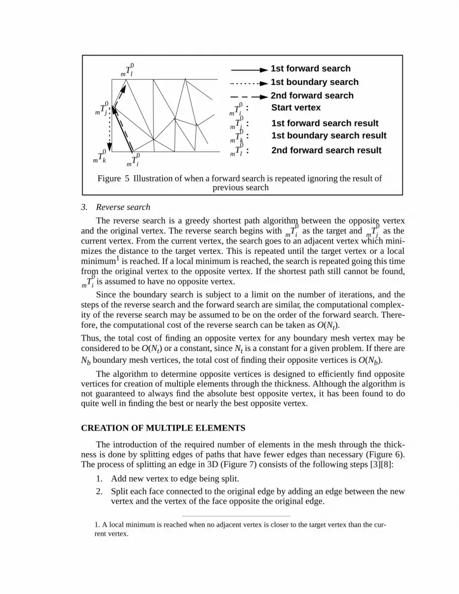
search ends on a vertex classified on the boundary of the original model face, the forwardsearch is repeated ignoring that vertex. The boundary search is then repeated with the newresult of the forward search (see Figure 5). Since the boundary search has a limit on thenumber of iterations (Nt), the computational cost of the boundary search isO(Nt).
T0
m i T2
g l[__
T0
m iT
2g l T
2g l T
0m i
T0
m kT
0m i
Face normal
: Start vertex
: Forward search result
: Boundary search result
: Shortest path
are opposite vertices
T0
m j
T0
m k
T0
m i
T1
m l T1
m m T1
m n, ,{ }T
0m j to T
0m i
T0
m iT
0m j&
fromT
1m n T
0m i
T0
m kT
0m jT
1m lT
1m m
Figure 4 Detection of locally “thin” sections
T2
g n T2
g l≠ T0
m i T0
m k
T0
m i
T0
m i T0
m j T2
g n[__
3. Reverse search
The reverse search is a greedy shortest path algorithm between the opposite vertexand the original vertex. The reverse search begins with as the target and as thecurrent vertex. From the current vertex, the search goes to an adjacent vertex which mini-mizes the distance to the target vertex. This is repeated until the target vertex or a localminimum1 is reached. If a local minimum is reached, the search is repeated going this timefrom the original vertex to the opposite vertex. If the shortest path still cannot be found,
is assumed to have no opposite vertex.
Since the boundary search is subject to a limit on the number of iterations, and thesteps of the reverse search and the forward search are similar, the computational complex-ity of the reverse search may be assumed to be on the order of the forward search. There-fore, the computational cost of the reverse search can be taken asO(Nt).
Thus, the total cost of finding an opposite vertex for any boundary mesh vertex may beconsidered to beO(Nt) or a constant, sinceNt is a constant for a given problem. If there areNb boundary mesh vertices, the total cost of finding their opposite vertices isO(Nb).
The algorithm to determine opposite vertices is designed to efficiently find oppositevertices for creation of multiple elements through the thickness. Although the algorithm isnot guaranteed to always find the absolute best opposite vertex, it has been found to doquite well in finding the best or nearly the best opposite vertex.
CREATION OF MULTIPLE ELEMENTS
The introduction of the required number of elements in the mesh through the thick-ness is done by splitting edges of paths that have fewer edges than necessary (Figure 6).The process of splitting an edge in 3D (Figure 7) consists of the following steps [3][8]:
1. Add new vertex to edge being split.
2. Split each face connected to the original edge by adding an edge between the newvertex and the vertex of the face opposite the original edge.
1. A local minimum is reached when no adjacent vertex is closer to the target vertex than the cur-rent vertex.
Figure 5 Illustration of when a forward search is repeated ignoring the result ofprevious search
T0
m iT
0m k
T0
m j
T0
m l
: Start vertex
: 1st forward search result: 1st boundary search resultT
0m k
T0
m j
T0
m i
: 2nd forward search resultT0
m l
1st forward search
1st boundary search
2nd forward search
T0
m i T0
m j
T0
m i

3. Split each region connected to the original edge by creating an interior facebetween the new vertex and the vertices of the region opposite the original edge.
4. Update the classification of all newly created entities. New entities inherit classifi-cation from the appropriate original entities.
The edges of a path to be split are picked in decreasing order of their lengths. If thereare fewer edges in the path than vertices to be added, edges may be split more than once.Edge split points are determined by bisection and subsequent snapping of the calculatedpoint to the boundary, if the edge is a boundary edge. If snapping to the boundary resultsin the new regions being invalid, the edge is not split.
Since splitting of edges changes the paths determined in the initial opposite vertexsearch, the path information is updated as its edges are being split. This is more efficientthan redoing the opposite vertex search.
REALIGNMENT OF EDGES
From Figure 6 it can be seen that splitting of path edges
1. creates new deficient paths through the thickness,
2. creates large number of connections at some vertices, and
3. results in large face angles (in 2D) and dihedral angles (in 3D).
Therefore, realignment of the diagonal mesh edges is necessary along and perpendic-ular to the thickness direction as shown in Figure 8. The realignment of edges is accom-plished through the use of edge swapping [3][8]. The process of edge swapping isequivalent to retriangulation of the polyhedron formed by deletion of all regions con-nected to the edge such that the new triangulation does not contain any new points anddoes not contain the edge being swapped (Figure 9).
Definition: A mesh edge, , is defined as anopposite edge of another mesh edge,
, if each of the vertices of are opposite to one of the vertices of .
Figure 6 Creation of multiple elementsthrough the thickness by edge splitting in 2D
Figure 7 Edge splitting example in 3D
a
a’
b
b’
c
c’
d
d’
e
e’
f
f’
g
g’
h
h’
i
i’
Initial mesh with opposite vertices identified
Mesh with path edges split
Edge to be split
T1
m j T2
g n[__
T1
m i T2
g l[__ T
1m j T
1m i

Definition: A mesh face, , is defined as anopposite faceof another mesh face,
, if each of the edges of is opposite to one of the edges of .
The knowledge the special mesh topology created by splitting is used in the identifica-tion of mesh edges to swap and the sequence in which to swap them. The identification ofedges to swap is facilitated by abstracting portions of the mesh between opposite faces aswedges (triangular prisms). The lateral faces of such wedges are abstracted as triangulatedquadrilaterals. For example, shown in Figure 10 is a portion of a mesh in which multiple
elements have been introduced through the thickness. In the figure, and are
opposite faces of and respectively. One of the 5 abstracted quadrilaterals shown
is formed by the vertex set . The two wedges shown are formed by
the vertex sets and .
Figure 8 Realignment of edges along andperpendicular to thickness direction
Figure 9 Edge swapping example in 3D
Figure 10 Abstraction of mesh between opposite faces as wedges
Mesh with path edges split
Mesh with edges realigned
Edge to be swapped
T2
m j T2
g n[__
T2
m i T2
g l[__ T
2m j T
2m i
T2
m 1 T2
m 2
T2
m 4 T2
m 3
T0
m 2 T0
m 6 T0
m 8 T0
m 4, , ,{ }
T0
m 1 T0
m 2 T0
m 3 T0
m 5 T0
m 6 T0
m 7, , , , ,{ } T0
m 2 T0
m 1 T0
m 4 T0
m 6 T0
m 5 T0
m 8, , , , ,{ }
T0
m 3
T0
m 7
T0
m 2
T0
m 6
T0
m 4
T0
m 8
T0
m 1
T0
m 5
T2
m 4
T2
m 2T2
m 3 T2
m 1 Thickness of wedge

The triangulation on a quadrilateral resulting from edge splitting and the triangulationdesired after realignment is shown in Figure 11. The former triangulation is called adiag-onal triangulation while the latter azigzag triangulation. A wedge has a diagonal or a zig-zag configuration if all of its quadrilateral faces have a diagonal or a zigzag triangulationrespectively (Figure 11). Note that the sides of the quadrilaterals in the thickness directionare edge paths between opposite vertices.
With this abstraction defined, the process of realigning edges along and perpendicularto the thickness direction can be viewed as a conversion of all triangulated quadrilateralsin the mesh from a diagonal to a zigzag configuration. This allows the edge realignmentprocess to be driven largely by topological considerations and is therefore more efficientthan using geometric criteria.
The conversion of the diagonal triangulation on each quadrilateral to zigzag is done ina templated sequence of swaps illustrated in Figure 12. This sequence can be easily gener-alized for a quadrilateral with any number of edges through its thickness.
If wedge topology is not present in a portion of the mesh, it is still possible to intro-duce multiple elements through the thickness and realign mesh edges to eliminate defi-cient paths through the thickness. For general mesh topology through the thickness, edgesmay be realigned using geometric criteria such as the thickness direction in the localneighborhood. A special situation dealt with in the algorithm is two adjacent mesh verti-ces having the same opposite mesh vertices (Figure 11). In this case, the edge in each pathconnected to the opposite vertex is ignored and the remaining edges used for the quadrilat-eral abstraction. Swapping of edges then proceeds as usual with this topology.
The description of the realignment procedure until now assumed that multiple ele-ments were introduced into a mesh which had only one element through the thickness. Ifthe initial mesh had more than one element through the thickness and additional elementswere introduced, then the multiple wedges, stacked on top of each other, would existbetween opposite faces. The procedures for recognition of quadrilaterals and wedges mustaccount for this. Once the individual wedges through the thickness have been identified,the swapping sequence can be applied to the quadrilateral faces of the wedge as before.
When converting a quadrilateral triangulation from diagonal to zigzag, care must be
Figure 11 Diagonal and zigzag configurations for quadrilaterals, triangles and wedges
swappededge
new edge
Figure 12 Conversion of a diagonal triangulation to zigzag via sequence of edge swaps

taken that wedges on either side of the quadrilateral are not forced into a configuration forwhich a tetrahedronization does not exist. The following rules may be stated about thevalidity of wedge configurations with 2 elements through the thickness:
Rule 1:If the directions1 of triangulations of all 3 quadrilaterals of a wedge are the same,then the wedge cannot be tetrahedronized, regardless of the type of the triangulations.Rule 2: If 2 of the triangulations are diagonal, their directions must be opposite for thewedge to have a valid tetrahedronization. The direction of triangulation of the third quad-rilateral is immaterial.Rule 3:If 2 of the triangulations are zigzag, at least their directions must be the same forthe wedge to have a valid tetrahedronization. In addition, if the third triangulation is zig-zag, its direction must not violateRule 1; if it is diagonal, its direction is immaterial.
If the number of edges through the thickness of the wedge is more than 2, then novalid tetrahedronization is possible with 1 diagonal and 2 zigzag triangulations (i.e.Rule 3no longer holds).Rule 1 andRule 2 are still valid for this case.
The invalidity of all wedge configurations with two zigzag and one diagonal triangu-lation for wedges with more than two elements through their thickness places an importantrestriction on the mesh enrichment process. This restriction is that multiple elements mustbe introduced iteratively with edges through the thickness being split only once before therealignment procedure is applied to the modified mesh. Therefore, if an initial mesh hasone element through the thickness everywhere andNt elements have been requestedthrough the thickness, the splitting and realignment process has to be performedlog2Nttimes rounded off to the next integer. To lift this restriction, the local nature of the diago-nal to zigzag conversion process must be sacrificed and propagated out into the mesh.
If a quadrilateral triangulation could not be converted to zigzag due to one of itsadjoining wedges becoming invalid, it is revisited later to account for the possibility thatother quadrilaterals in the local neighborhood may have been changed to zigzag allowingfor successful conversion. Still, in their current form, the realignment procedures may beprevented from converting all quadrilateral triangulations to zigzag by the invalidity ofcertain wedge configurations, even with two edges through the thickness. Work is inprogress to allow conversion of any quadrilateral by modifying the triangulation of otherquadrilaterals in the neighborhood. Work is also in progress to delete the elements forminga wedge and tetrahedronizing the wedge in its new configuration using templates, a moreefficient process than swapping successively.
1. The direction of triangulation of a quadrilateral is defined with respect to a wedge using thequadrilateral. It is determined by the orientation of the diagonal edges of a triangulation when look-ing at a quadrilateral such that the wedge is behind the quadrilateral.
Figure 13 Valid wedge configurations Figure 14 Invalid wedge configurations

PRE- AND POST-PROCESSING
The success of the realignment procedures to identify wedge configurations partlydepends on the initial mesh having matching faces through the thickness. Since a meshobtained from an unstructured mesh generator is not guaranteed to have this topology, pre-processing procedures are necessary to obtain this form. These procedures currently relyon edge swapping to introduce structure in the mesh through the thickness, but use of edgesplitting and collapsing is also proposed. From a geometric point of view, it is desirable toalign opposite vertices along the average normal direction of the opposite model faces toimprove the quality of elements generated by the main procedures. Node repositioningwith iterations in parametric space of surfaces is proposed for this purpose.
A post processing step to improve the quality of the mesh is applied after the genera-tion of multiple elements. This procedure is a generalized mesh optimization procedurewhich relies on local mesh modification to improve large dihedral angles. These proce-dures are prevented from collapsing edges which have been introduced into the thicknessto eliminate deficient paths or from swapping edges which have been realigned.
RESULTS
Figure 15 shows the initial mesh and a mesh with 4 elements through the thickness fora model with thin sections. The close-up pictures show the interior of a portion of the ini-tial and final meshes. It can be seen from the figure, that the final mesh has the requirednumber of elements through the thickness nearly everywhere in the domain. Also, theswapping procedures did a good job of creating zigzag triangulations through the thin sec-tions thereby eliminating most deficient paths through the thickness.
Figure 15 Initial mesh and mesh with 4 elements through the thickness formodel asm110. Zoom-in shows interior of initial and final meshes

Figure 16 shows the initial and final meshes for another model with thin sections. Asbefore, the locally deficient portions of the initial mesh have been identified very well andmultiple edges created in paths through the thickness. Although the realignment proce-dures were also successful in converting a large number of the triangulations to the desiredform, there are still some edges that could not be realigned.
Figure 17 shows a mesh with multiple elements through the thickness for a modelwith a number of thin sections and solid portions interacting in a complex manner. Themodel represents a sector of a combustor casing with gating attached for casting. Thoughthe model is not of a real part, its complexity is comparable to the real parts developed bythe same user. It can be seen that the procedures deal with this general domain quite well,although the performance of the realignment procedures needs to be improved.
CONCLUSIONS
This paper presented a method for anisotropically refining meshes to generate a userspecified number of elements through the thickness. The method consisted mainly of iden-tifying opposite vertices for mesh vertices on each model face, introducing the requirednumber of edges between opposite vertices by edge splitting, and then swapping meshedges to eliminate new deficient paths created by the splitting. A mechanism was pro-posed for realigning edges more efficiently and in a locally optimum manner by abstract-ing groups of elements through the thickness as wedges, whenever such a structure existsin the mesh. Using this mechanism, it was seen that the current method was constrained inthe number of elements added through the thickness at a time and in the realignment ofedges by the invalidity of some wedge triangulations.
Results were presented showing meshes for three complex models with multiple ele-ments through the thickness. It was seen that the procedures to identify locally deficientparts of meshes and refine them in the thickness direction worked well for all the models.
Figure 16 Initial and refined mesh of model asm107, with close-ups of thin sections

The realignment procedures also did a good job of converting diagonal triangulations tozigzag but were not successful all the time.
Future work with this method will focus largely on the issue of eliminating all defi-cient paths through the thickness in the mesh. Enhancements in progress include tem-plated tetrahedronization instead of sequential edge swapping for conversion of wedges,enhancement of pre-processing algorithm and improvement of quality of mesh.
ACKNOWLEDGEMENTS
This work was supported by the ARPA Investment Casting Cooperative Arrangement.
REFERENCES
1 Simpson, R.B., “Anisotropic Mesh Transformations and Optimal Error Control,”Applied Numerical Mathematics v 14, pp. 183-198, 1994.
2 Beall, M.W.,SCOREC Mesh Database, Version 2.3, Users Guide, Scientific Computa-tion Research Center, Rensselaer Polytechnic Institute, Troy, NY 12180, 1994.
3 de l’Isle, E.B., George, P.L., “Optimization of Tetrahedral Meshes,” INRIA, Domainede Volceau, Rocquencourt, BP 105, Le Chesnay, France, 1993.
4 Mavriplis, D.J., “Adaptive Mesh Generation for Viscous Flows using Delaunay Trian-gulation,”Journal of Computational Physics v 90, pp. 271-291, 1990.
Figure 17 Mesh with 4 elements through the thickness for part representing a sector ofcombustor casing with gating attached for casting. (Courtesy PCC Airfoils, Inc.)

5 Hassan, O., et.al., “Mesh Generation and Adaptivity for the Solution of CompressibleViscous High Speed Flows,”Int. J. Num. Meth. Engng. v 38 n 7, pp. 1123-1148, 1995.
6 Kallinderis, Y., Khawaja, A., McMorris, H., “Hybrid Prismatic/Tetrahedral Grid Gen-eration for Complex Geometries,”33rd Aerospace Sciences Meeting and Exhibit,Reno, NV, Jan 95.
7 Lohner, R., “Matching Semi-Structured and Unstructured Grids for Navier-StokesCalculations,”AIAA paper 93-3348-CP, 1993.
8 de Cougny, H.L., Shephard, M.S., “Local Modification Tools for Adaptive MeshEnrichment and Their Parallelization,”Unpublished report, SCOREC, RensselaerPolytechnic Institute, Troy, NY, 1995.
9 Shephard, M.S., Georges, M.K., “Automatic Three-Dimensional Mesh Generation bythe Finite Octree Technique”Int. J. Num. Meth. Engng. v 32 n 4, pp. 709-749, 1991.
10 Shape Data Limited, Parker’s House, 46, Regent Street, Cambridge CB2 1DB,England.PARASOLID v6.0 Programming Reference Manual, August 1994.
11 Weiler, K.J., “The Radial-Edge Structure: A Topological Representation for Non-Manifold Geometric Boundary Representations,” inGeometric Modeling for CADApplications, ed. Wozny, M.J., et. al., pp. 3-36, North Holland, 1988.