protrusion-oriented 3d mesh segmentation
TRANSCRIPT

The Visual Computer manuscript No.(will be inserted by the editor)
Alexander Agathos · Ioannis Pratikakis · Stavros Perantonis ·Nickolas S. Sapidis
Protrusion-oriented 3D Mesh Segmentation
Abstract In this paper, we present a segmentation algo-rithm which partitions a mesh based on the premise thata 3D object consists of a core body and its constituentprotrusible parts. Our approach is based on prominentfeature extraction and core approximation and segmentsthe mesh into perceptually meaningful components. Basedupon the aforementioned premise, we present a method-ology to compute the prominent features of the mesh,to approximate the core of the mesh and finally to tracethe partitioning boundaries which will be further refinedusing a minimum cut algorithm. Although the proposedmethodology is aligned with a general framework intro-duced by Lin et. al. [13], new approaches have been in-troduced for the implementation of distinct stages of theframework leading to improved efficiency and robustness.The evaluation of the proposed algorithm is addressed ina consistent framework wherein a comparison with thestate of the art is performed.
Keywords Mesh segmentation · Prominent Featureextraction · Core Approximation
1 Introduction
3D mesh segmentation is the process which separates amesh into disjoint connected components. It is an impor-tant process for many applications in Computer Graph-ics like metamorphosis [18], compression [17], 3D shaperetrieval [24], 3D object recognition [19], texture map-ping [11], etc.As previously discussed in [1,15] there are mainly two
A. Agathos · I. Pratikakis · S. PerantonisComputational Intelligence LaboratoryInstitute of Informatics and TelecommunicationsNCSR ‘Demokritos’, GreeceE-mail: {agalex,ipratika,sper}@iit.demokritos.gr
N. Sapidis · A. AgathosDepartment of Product and Systems Design EngineeringUniversity of the Aegean, GreeceE-mail: [email protected]
Fig. 1 Segmentation of a human figure into its meaningfulconstituent parts. Each part is shown with a different color
types of segmentation. In the first, namely, surface-based,the mesh is segmented into patches for which either ba-sic primitives can be fitted or various criteria requiredby the application should be satisfied. In the second,namely part-based, the mesh is divided into volumet-ric parts that are perceptually meaningful.In this paper, we will present a new part-based segmen-tation algorithm which is based on the premise that a3D object consists of a core body and its constituentprotrusible parts. For example, the proposed algorithmsegments a 3D object representing a human into the mainbody along with the head, hands and legs (see Fig. 1).
The contribution of this paper is twofold :
i. A novel way to trace the partitioning boundaries ofthe 3D object using closed boundaries constructedwith the aid of a distance function;
ii. A novel algorithm for the core approximation of the3D object.
The proposed methodology leads to meaningful segmen-tation results that are proven after evaluation which isaddressed in a consistent framework wherein a compari-son with the state of the art is performed.

2 Alexander Agathos et al.
This paper is organized as follows. Section 2 discussesthe related work. Section 3 is dedicated to the detaileddescription of the proposed methodology. In Section 4,the experimental results are discussed while in Section 5conclusions are drawn.
2 Related Work
As discussed in [1], 3D mesh segmentation algorithmscan be categorized according to the core methodologyused namely, (i) Region growing; (ii) Watershed-based;(iii) Reeb graphs; (iv) Model-based; (v) Skeleton-based;(vi) Clustering; (vii) Spectral analysis; (viii) Explicit Bo-undary Extraction; (ix) Critical points-based; (x) Mul-tiscale Shape Descriptors; (xi) Markov Random Fieldsand (xii) Direct segmentation.These categories consist of algorithms that produce seg-mentation in either a surface-based or a part-based fash-ion. In this paper we will focus on part-based algorithmswhich can be further classified based upon the under-lying concept used. The most commonly used conceptscomprise (i) the minima rule; (ii) the connection of theshape’s volume to the mesh surface; (iii) Hierarchicalclustering; (iv) Skeleton-driven segmentation; (v) Salientpoint and Core estimation.
The minima rule concept was introduced by Hoffmanand Richards [5] and relies on the principle wherein anobject is segmented by human perception at areas of con-cavity.Zhang et. al. [22] use the minima rule and construct aregion growing algorithm. Seed vertices that do not be-long on concavities are expanded creating regions thatare surrounded by deep concavities. Their algorithm isable to segment meshes into volumetric parts providedthat the boundaries of the part contain deep concavities.Page et. al. [14] try to conform to the minima rule with aalgorithm. In this, a watershed-based algorithm a topo-graphic surface, which is defined using a height function,is flooded. At the points where the flooded regions meet,watershed lines are created signifying the boundaries ofdistinct parts. The normal curvature of the surface of theobject is used as the height function.Wu and Levine [21] take also advantage of the minimarule and construct a model-based algorithm. Specifically,they create a surface model of the mesh and apply thetheory of the electrical charge distribution across the sur-face and use its correlation with the minima rule, i.e. thedensity charge is very low at areas of deep concavitiesand high at the convexities of the surface. Thus, by trac-ing the local minima in the electrical charge density theboundaries of the parts can be traced.The drawback of the above three algorithms is that theboundaries must contain concavities. Unfortunately, thisis not often the case for many objects, (eg. the boundary
between the arm and the main body in a human).So far, from the aforementioned segmentation algorithmsthat use the minima rule it can be seen that all of themlocalize at the concavities of the mesh in order to seg-ment without using any other information concerning theshape of the mesh.Lee et. al. [10] use the minimum curvature of the mesh inorder to construct the boundaries of its parts. The mainadvantage of their approach is that they manage to con-struct closed boundaries of the parts even if they are notsurrounded by deep concavities. This is achieved by anefficient shortest path algorithm, which drives the openboundary along the mesh so as to close in a perceptu-ally meaningful manner. Although their algorithm man-ages to overcome the main problem that the other threeaforementioned algorithms have, there exist cases in theiralgorithm where some extracted boundaries do not par-tition the mesh into perceptually meaningful parts.Katz and Tal [7] use a combination of geodesic distanceand concavity information in order to create clusterswhich contain perceptually coherent regions. Since con-cavity is considered in their clustering method, they alsoconform to the minima rule. However, the clustering de-pendence on the concavity information reduces robust-ness on a mesh with a lot of geometric texture.Zhang and Liu [23] find two faces of the mesh that belongon two perceptually different parts and apply a Normal-ized Cut Algorithm like in [17] in order to segment themesh at deep concavities into two parts, thus conformingto the minima rule. They apply their method recursivelyin order to acquire a full decomposition of the object.As in [7], their algorithm does not work well on a meshwith a lot of geometric texture. Also, in the recursivedecomposition they apply, it is not possible to define ameaningful hierarchy as small parts of the object mightbe segmented prior to bigger more salient parts.
Another concept which appears in mesh segmentationmethodologies is based on the connection of the shape’svolume to the mesh surface. Such a concept was pre-sented by Kim et. al. [9], who created a volumetric methodto partition the object. Their aim is to extract the convexparts of the object. This is achieved by first doing a vox-elization of the mesh and then maximizing the weightedconvexity of the parts produced after a morphologicalopening on the voxelised grid with a sphere as a shapeelement.Also, in Shapira et. al. [16] a volumetric function is cre-ated which is called the Shape Diameter Function. Thisfunction is defined on the vertices of the mesh and equalsto the average of the distances of a set of rays cast fromthe surface point in opposite directions from its normal.They use this function in a clustering algorithm in or-der to create a hierarchical characterization of the meshwhich is later used by a k-way graph-cut algorithm toseparate smoothly the distinct parts.
Protrusion-oriented 3D Mesh Segmentation 3
The idea behind hierarchical clustering lies upon edgecontraction on the dual graph of the mesh [1]. With eachedge contraction in the dual graph a new node on the hi-erarchical structure is generated whose children are thenodes incident to the edge and the two areas that rep-resent the children nodes are grouped into their parentcommon cluster. The edge contraction cost is applicationdriven.Attene et. al. [3] uses the hierarchical clustering conceptto classify the mesh triangles into clusters that can be ap-proximated by either a plane or sphere or cylinder primi-tive. The contraction cost of a dual edge is the minimumof the errors generated after fitting the plane, sphere andcylinder primitives to the triangles of the merged regions.The primitive corresponding to the minimum fitting er-ror approximates the unified cluster.
The skeleton-driven segmentation concept uses the skele-ton of the 3D object in order to extract the meaningfulparts of the 3D object.Li et. al. [12] segment the mesh using the skeleton ofthe object. The skeleton of the object is constructed byperforming simplification of the surface using the edgecontraction method. The priority for contraction is thelength of the edge to be contracted. Their simplifica-tion process leaves edges that do not have incident tri-angles unaltered, they call these edges skeletal. At theend of the contraction process only skeletal edges areleft, whose union is the skeleton of the object. The par-titioning boundaries of the object are extracted by usinga plane which sweeps the mesh along the skeleton edges.The intersection of the plane and the mesh is one ormore polygon contours. The segmentation areas are ex-tracted by examining the way that these contours alteras the sweep plane moves. For this purpose, a paramet-ric geometric and topological function is defined on thesecontours.
The concept that takes into account the salient points(prominent features residing at the extrema of the mesh)and core estimation aims to the extraction of other indi-vidual parts that do not belong to the main body (core)of the mesh. In Katz et. al. [8] multidimensional scaling isused in order to create a pose invariant representation ofthe object. This representation aids in the computationof the salient points of the surface and then the salientpoints along with the representation are used in order toextract the core by spherical mirroring. Their algorithmrequires to compute a coarse model (approximately 1000faces) of the mesh using a simplification algorithm in or-der to run in a reasonable time and not to overflow thecomputer’s memory.In Valette et. al. [20] the principle of the protrusion func-tion [1] is used to express the degree of closeness of avertex to a protrusible part. Specifically, the evolutionof the protrusion function from its high towards its lowvalues is used in order to extract the protrusions of the
mesh and separate them from the main body. Althoughthe protrusion function does not have pose sensitivitytheir algorithm does (see Section 4). Furthermore, thesegmentation boundaries are usually not extracted onthe areas where human perception would naturally do.Lin et. al. [13] find also the salient points of the mesh anda core approximation. Each of the salient points creategeodesic zones which are called locales. These locales areused to define a border function which identifies thoselocales containing the boundary of the protrusion. Themain drawback with their approach is that some of theirparameters are not set fixed and depend on the localeswhich in turn depend on the resolution of the mesh. Also,their core approximation relies on a fixed threshold whichcan significantly overestimate or underestimate the coreof the mesh.In this paper, the proposed algorithm is based on thesalient point and core estimation concept. It efficientlymakes an approximation of the main body of the 3D ob-ject while the partitioning boundaries are found usingsweeping closed boundaries which first, do not dependon the resolution of the mesh as the locales do in [13]and second, are far less susceptible to noise.
3 The proposed methodology
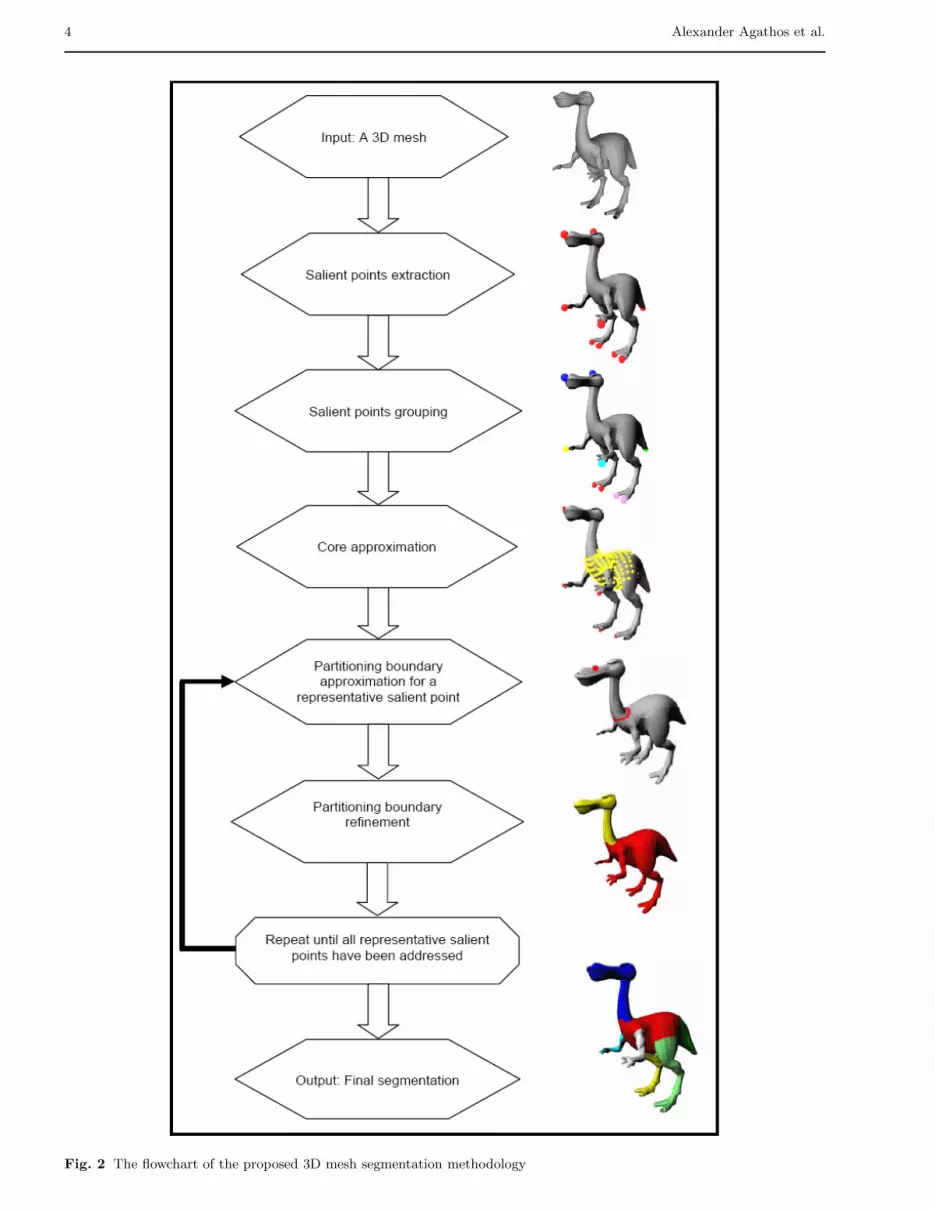
Our objective is to segment a 3D mesh into its meaning-ful components. To this end, we propose a methodologywhich consists of the consecutive steps in the following.
i. The salient points of the mesh are extracted. Thesepoints are the extrema of the mesh and characterizeits protrusions;
ii. The salient points extracted in step (i) are groupedaccording to their geodesic proximity;
iii. An approximation of the core (main body) of themesh is found using the grouped salient points fromstep (ii);
iv. The partitioning boundaries are detected using closedboundaries along the protrusions constructed by adistance function;
v. The detected partitioning boundaries are refined.
The flowchart showing the steps which will be followedby the proposed methodology is shown in Fig. 2.A detailed description of the aforementioned steps isgiven in the following sections.
3.1 Salient Points - Extraction stage
In this section, we describe the process of finding thesalient points of the 3D object.In order to realize this process, a function is going to beused which has the property of having low values at thecenter of the 3D object and high values at its protrusions[4]. This function is called in [1] protrusion function, pf().
4 Alexander Agathos et al.
Fig. 2 The flowchart of the proposed 3D mesh segmentation methodology
Protrusion-oriented 3D Mesh Segmentation 5
Formally, for each point v of the surface S of a 3D object,the protrusion function is defined as :
pf(v) =
∫p∈S
g(v, p) dS (1)
where g(v, p) denotes the geodesic distance between v, p[4]. Usually, this function is approximated on a 3D meshby a tessellation of its surface in compact regions, suchthat (1) is transformed to :
pf(v) =∑i
g(v, bi) area(Vi) (2)
where bi denotes the center of the region Vi.Also, another approximation of the protrusion functionmight alternatively be used as in [4]:
pf(v) =∑vi∈S
g(v, vi) (3)
where vi denotes the vertices of the mesh.Since the protrusion function has the aforementionedproperty and salient points of the mesh reside at the ex-trema of the mesh it is natural to search for them at thelocal maxima of the function, i.e. for each vertex v ∈ S aneighborhood of vertices Nv is considered, v is a salientpoint of the mesh if: pf(v) > pf(vi), ∀ vi ∈ Nv.The neighborhood Nv can be either:i. a k-ring neighborhood defined as the set of vertices
within k edges away from vertex v;ii. a geodesic neighborhood defined as the set of vertices
for which the geodesic distance from vertex v is lessthan a threshold. This threshold is called the radiusof the geodesic neighborhood.
In Katz et. al. [8] a 1-ring neighborhood is used. Sincea 1-ring neighborhood can be susceptible to noise theirpose invariant representation is used in order to filterthe candidate salient points. In Lin et. al. [13] a geodesicneighborhood is used.In our approach, similar to [13], a geodesic neighbor-
hood is used with radius√5 · 10−3 · area(S) as in [4]. In
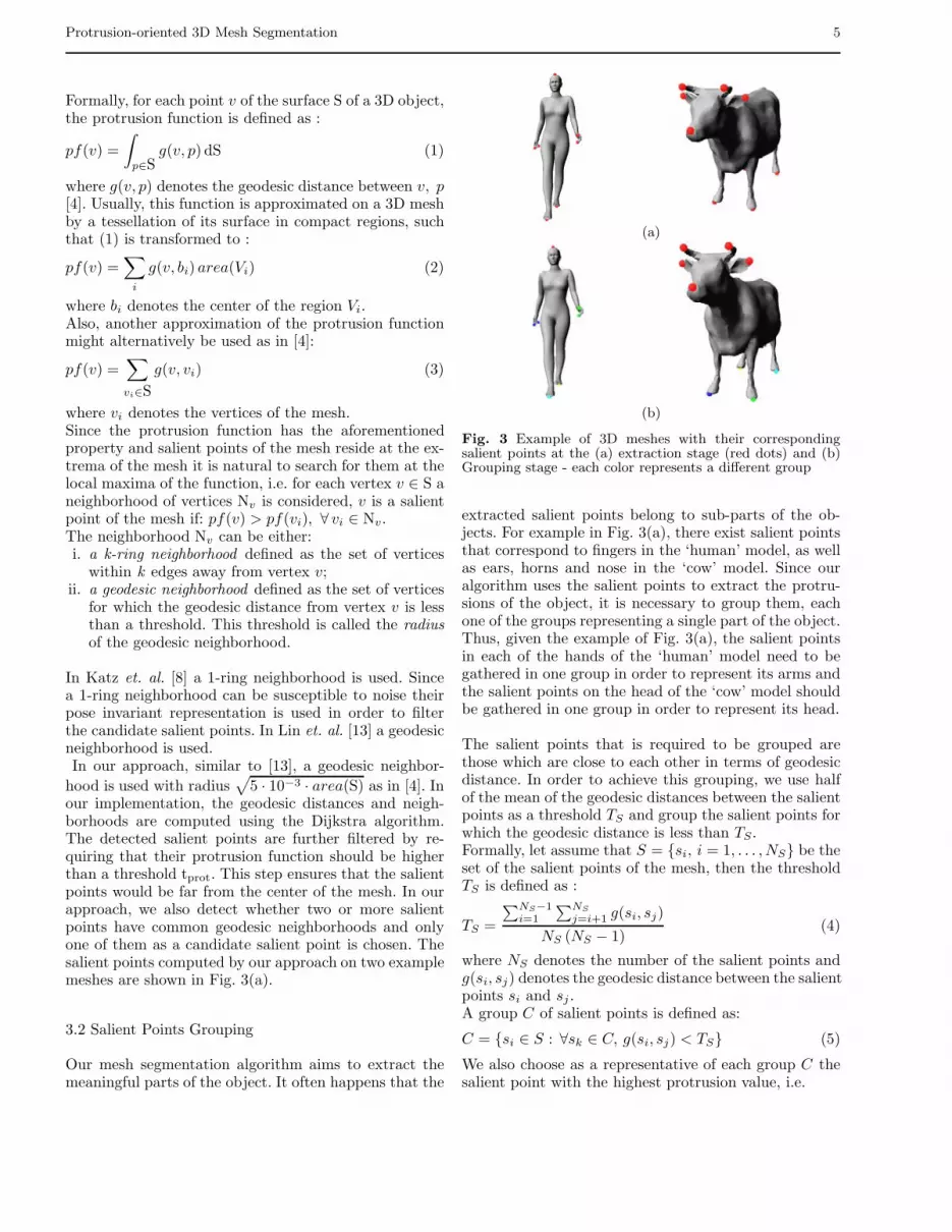
our implementation, the geodesic distances and neigh-borhoods are computed using the Dijkstra algorithm.The detected salient points are further filtered by re-quiring that their protrusion function should be higherthan a threshold tprot. This step ensures that the salientpoints would be far from the center of the mesh. In ourapproach, we also detect whether two or more salientpoints have common geodesic neighborhoods and onlyone of them as a candidate salient point is chosen. Thesalient points computed by our approach on two examplemeshes are shown in Fig. 3(a).
3.2 Salient Points Grouping
Our mesh segmentation algorithm aims to extract themeaningful parts of the object. It often happens that the
(a)
(b)
Fig. 3 Example of 3D meshes with their correspondingsalient points at the (a) extraction stage (red dots) and (b)Grouping stage - each color represents a different group
extracted salient points belong to sub-parts of the ob-jects. For example in Fig. 3(a), there exist salient pointsthat correspond to fingers in the ‘human’ model, as wellas ears, horns and nose in the ‘cow’ model. Since ouralgorithm uses the salient points to extract the protru-sions of the object, it is necessary to group them, eachone of the groups representing a single part of the object.Thus, given the example of Fig. 3(a), the salient pointsin each of the hands of the ‘human’ model need to begathered in one group in order to represent its arms andthe salient points on the head of the ‘cow’ model shouldbe gathered in one group in order to represent its head.
The salient points that is required to be grouped arethose which are close to each other in terms of geodesicdistance. In order to achieve this grouping, we use halfof the mean of the geodesic distances between the salientpoints as a threshold TS and group the salient points forwhich the geodesic distance is less than TS.Formally, let assume that S = {si, i = 1, . . . , NS} be theset of the salient points of the mesh, then the thresholdTS is defined as :
TS =
∑NS−1i=1
∑NS
j=i+1 g(si, sj)
NS (NS − 1)(4)
where NS denotes the number of the salient points andg(si, sj) denotes the geodesic distance between the salientpoints si and sj .A group C of salient points is defined as:
C = {si ∈ S : ∀sk ∈ C, g(si, sj) < TS} (5)
We also choose as a representative of each group C thesalient point with the highest protrusion value, i.e.

6 Alexander Agathos et al.
Rep(C) = {si ∈ C : pf(si) > pf(sk), ∀sk ∈ C}.The efficiency of our grouping method in representing themain parts of the ‘human’ and ‘cow’ models is shown inFig. 3(b).
3.3 Core approximation
In this section, we will present our core approximationalgorithm which is a crucial step in our approach. Bycore approximation, we mean the approximation of themain body of an object. An algorithm which approxi-mates the main body of the object is the one that canacquire all the elements (vertices or faces) of the meshexcept those that belong to the protrusions of the mesh.These elements should separate all the protrusions fromeach other.In Katz et. al. [8] this is achieved by spherical mirroringof the pose invariant representation of the mesh. Whenthey cannot achieve this entirely, they proceed in coreextension until all features are separated. In Lin et. al.[13] a simple thresholding of the protrusion function isused, i.e. they define that the core of the mesh are thepoints of the mesh whose value is lower than a predefinedthreshold. However, a fixed thresholding value is not re-liable since it might lead to a significant overestimationor underestimation of the main body.In our algorithm, the core approximation is addressed byusing the minimum cost paths between the representa-
tive salient points. Let assume that S = {si, i = 1, . . . ,NC} be the set of representative salient points, whereNC denote the number of clusters found in section 3.2and si the representative of the ith group. Also, let P ={Pij , i, j ∈ {1, . . . , NC}} be the set of all minimum cost
paths of the points of S, where Pij denote the minimumcost path between si, sj . The key idea of our core ap-proximation is to expand a set of vertices in ascendingorder of protrusion function value until the expanded settouches a certain percentage of all elements of P . Themotivation of this approach stems from the fact that theminimum cost paths cover a significant amount of theprotrusible parts, thus by expanding a set of vertices bythis way gives a guarantee that it will reach the protrusi-ble parts and cover also an area inside them. The pseudo-code for our core approximation algorithm is shown inFig. 4.First, the vertices of the mesh M are inserted in a priorityqueue PFHeap in which the vertices with the minimumpf() are inserted first. The vertices of the core approxima-tion are stored in a list CoreList. The algorithm proceedsby extracting points from the priority queue which incre-mentally expand the CoreList. Every point extracted isexamined whether it belongs in P . A path Pij in P re-mains active if the ratio of the number of vertices inthe path Pij which have been visited during expansionover the total number of vertices is less than tc. Thisthreshold denotes the aforementioned percentage of the
1: for all vertices v ∈ M do2: insert v in PFHeap with priority pf(v)3: end for4: StopGrowing = false5: while !StopGrowing do6: pop a vertex v from PFHeap7: if vCanBeAdded then8: CoreList.add(v)9: end if10: for all Pij ∈ P do11: if Pij .active then12: if v ∈ Pij then13: increment Pij .counter
14: ifPij .counter
Pij .SizeOfPath≥ tc then
15: Pij .active = false16: end if17: end if18: end if19: end for20: for all si ∈ S do21: if si.active then22: si.active = false23: for all sj ∈ S − si do24: if Pij .active then25: si.active = true26: end if27: end for28: end if29: end for30: //StopGrowing becomes true if all si be-
come non active31: end while
Fig. 4 The pseudo-code of the proposed core approximationalgorithm
points of the minimum cost path that the core approx-imation can touch. Using this threshold it is expectedthat the core approximation will cover even slightly theprotrusible parts that are traversed by the minimum costpath traces. A salient point si ∈ S remains active if ∃Pij
for some j ∈ {1,...,NC} �= i : Pij active. A vertex v ofthe Mesh CanBeAdded in CoreList if the nearest salientpoint in S is active. StopGrowing becomes ‘TRUE’ whenall salient points become non-active.
Our core approximation method has two main advan-tages over [8]:
i. There is no need to do multidimensional scaling, whichis a time consuming process, in order to extract thecore. Instead only the minimum cost paths are usedin order to check whether the core has expanded suf-ficiently. This implies far less complexity;
ii. We have introduced a percentage of minimum costpath traces that should be covered for the termina-tion of core expansion. Those traces span the pro-trusible parts at most. Thus, the selection of a per-centage of the traces provides a high confidence thatthe core points will cover areas of the protrusibleparts or being very close to the neighboring areas in

Protrusion-oriented 3D Mesh Segmentation 7
which the real boundary is situated. Several examplesare given in Fig. 13.
Fig. 5 illustrates our core approximation on two meshes.As it can be observed, our algorithm produces consistentapproximation of the core and its boundaries are nearthe actual boundaries identifying the initial approxima-tion of the partitioning boundaries.In general, it cannot be guaranteed that the core approxi-mation overlaps exactly the partitioning boundaries. Thishappens because the minimum cost paths reside mostlyin the protrusions and sometimes the core expands insidethem in order to achieve the percentage of the points ofthe minimum cost paths it should touch. Thus, a furtherstep is required that can detect the partitioning bound-aries.
3.4 Partitioning Boundary Detection
In this section, we will detail the stage of our algorithmthat detects the partitioning boundary, that is the bound-ary between a protrusion and the main body of the mesh.We consider that in the area that is enclosed by thedesired boundary between the protrusion and the mainbody, an abrupt change in the volume of the 3D objectshould occur, thus, our goal is to detect this change. Toaccomplish this, we construct closed boundaries whichare defined by a distance function D associated to asalient representative of the group which represents theprotrusion. The abrupt change of volume is detected byexamining the closed boundaries perimeter.
For each representative salient point s, the distance func-tion D is defined for each vertex v of the mesh as theshortest distance between v and s. The shortest distanceis computed using the Dijkstra algorithm with source sand cost for each edge (u, v) of the mesh denoted as :
cost(u, v) = δlength(u, v)
avg length+ (1− δ)
prot(u, v)
avg prot(6)
where prot(u, v) = |pf(u)−pf(v)| and avg length, avg p-rot denote the average values of the length and protru-sion difference of the edges of the mesh, respectively.This distance function was introduced in [13]. A properbalance between the two terms of equation (6) create aclosed boundary whose approximating plane is nearlyperpendicular to the principal direction of the corre-sponding protrusion. In our implementation, we set δequal to 0.4.The closed boundaries which are used in our algorithmare constructed by interpolating on the edges of the meshthe iso-contour generated by setting a constant value Dc
on D.The iso-contour CDc intersects the edge (u, v) of themesh if (D(u)−Dc)(Dc−D(v)) > 0 and the intersection
point is vint = (1− λ)u + λv, where λ =Dc −D(u)D(v)−D(u)
.
By tracing all the triangles which are incident to all the
(a) (b)
Fig. 5 Examples of core approximation for the 3D models‘human’ and ‘cow’. The vertices representing the core arecoloured in yellow
Fig. 6 The closed boundary approximating an iso-contourof the distance function D
intersecting edges, an approximation of this iso-contourcan be constructed which in most of the cases is a singleclosed boundary. In the case that more than one closedboundaries are generated, we choose the one with thelargest perimeter. In Fig. 6, an illustration of a closedboundary constructed by the method described above isshown.As already mentioned in section 3.3, our core approxi-mation has its boundaries near the actual boundaries ofthe distinct parts of the model. Taking advantage of thiswe set a predefined number lper of closed boundaries inthe area defined by the interval [(1 − d1)Dcoremin,(1 +d2) Dcoremin] wherein the real protrusion is situated.Dcoremin denotes the value of the distance function be-tween the nearest point of the core approximation andthe representative s, d1, d2 denote the extent of the in-terval (0 < d1 < 1, d2 > 0). For the approximation of thepartitioning boundary, the area of the aforementioned in-
terval is swept in fixed steps equal to e =(d1+d2)Dcoremin
lper.
Sweeping of the area will be terminated when the changeof the perimeter between successive closed boundarieswill be greater than a threshold.Specifically, let peri be the perimeter of the ith closed
8 Alexander Agathos et al.
boundary. We define the ratios:
ri =
⎧⎪⎨⎪⎩
peri+1peri if peri+1 > peri
periperi+1
if peri+1 ≤ peri
, i = 1, . . . , lper (7)
These ratios represent the change of the perimeter be-tween successive closed boundaries. Our algorithm searchesfor rk which is the first ratio that is greater than a thresh-old rmax that has been defined experimentally and setsthe kth closed boundary as the partitioning boundary.If such a ratio cannot be found, the algorithm finds themaximum ratio rkmax and sets the kthmax closed bound-ary as the partitioning boundary. In this way, we detectthe aforementioned abrupt change in the volume of theobject at the boundary between its main body and theprotrusion.
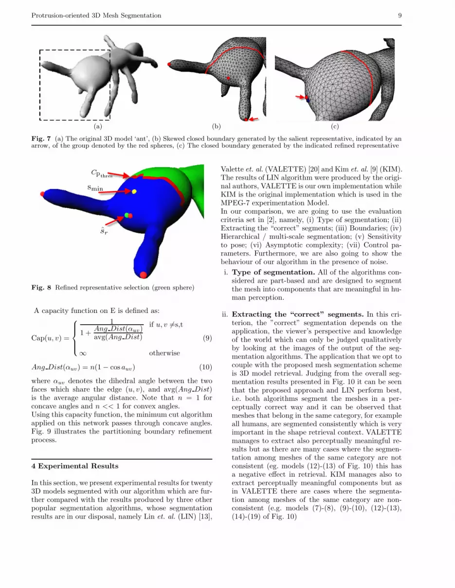
Initially, in our algorithm we have chosen the simple so-lution to select the representative of the group, definedin section 3.2, as the source point from which the dis-tance function D is computed. This choice may lead tothe creation of skewed closed boundaries near the realboundary of the protrusion. This has the consequencethat the algorithm may not be able to trace the realboundary properly as it will largely deviate from it. SeeFig. 7(b) for a demonstration of this problematic case.In the sequel, we present how to find a proper refinedrepresentative sr in order to be used instead of the repre-sentative of the group. The proper refined representativeshould create closed boundaries that are parallel to theprotrusion boundary like the one presented in Fig. 7(c).In order to find the proper refined representative in agroup of salient points we proceed as follows.First, we find the vertex smin of the mesh for which thedistance to all of the salient points in the group is mini-mal. Then, we find the point cmin of our core approxima-tion with the minimum geodesic distance from smin. Thegeodesic distance of smin and cmin is denoted as dmin. Af-terwards, we find the point pthres which is the first pointon the minimum cost path from smin to cmin for whichthe geodesic distance from smin is greater than 0.3dmin.Next, we consider the iso-contour Cpthres
generated bythe protrusion function by setting it to the constant valuepf(pthres). The part of the iso-contour which belongs tothe protrusion of the object being examined is close tothe salient points of the group and in most of the casesits best fit approximating plane is nearly perpendicularto the principal direction of the protrusion. We approxi-mate this contour using the same interpolating techniquediscussed above.We then take into account only the part of the meshwhich contain smin and is constrained by Cpthres
forwhich we compute the protrusion function. The refinedrepresentative sr will be the point of the constrainedmesh with the minimum value of the protrusion func-tion.
In Fig. 8 we illustrate this process. The salient pointsthat belong to the group are the red spheres. The yellowsphere represents smin and the red line approximates theiso-contour Cpthres
(the red line is generated by the tri-
angles that Cpthresintersects). The refined representative
sr is the point of the constrained mesh (coloured in blue)with the minimum protrusion value and is illustrated bythe green sphere.
3.5 Partitioning boundary refinement
The partitioning boundary detected in section 3.4 is aclosed boundary approximating an iso-contour of the dis-tance function D. In most of the cases this boundary is arough approximation of the true protrusion boundary ofthe object, thus it has to be refined and placed accord-ing to Hoffman and Richards [5] at the concavities of theobject.In order to achieve this, we use the minimum-cut method-ology as in Katz and Tal [7]. Specifically, we constructa flow network graph using the dual graph of the mesh.In order to construct the network, three regions shouldbe defined. Specifically, we define a region A containingthe triangles of the protrusion of the mesh, a region Cwhich is going to contain the partitioning boundary anda region B containing the faces of the rest of the mesh.RegionC is constructed as follows. First we find the aver-age geodesic distance, denoted as AvgGeodDist, betweenthe boundary extracted in section 3.4 and the refinedrepresentative calculated also in the same Section. Then,regionC is defined as the triangles of the mesh which ver-tices geodesic distance from the refined representative lieall in the interval [0.9·AvgGeodDist, 1.1·AvgGeodDist].This interval denotes a small area around the estimatedpartitioning boundary where it is expected that the truepartitioning boundary should reside.The set A is constructed by performing a breadth firstsearch starting from the refined representative of the pro-trusion until region C is reached.Let VC, EC be the nodes and edges of the graph rep-resenting C. Let VCA be the nodes of the graph whichrepresent the triangles of A that share a common edgewith the triangles of C, and VCB be the nodes of thegraph which represent the triangles of B that share acommon edge with the triangles of C.The flow network graph G = (V, E) is constructed byadding also two more nodes s, t, and V, E are definedas:
V = VC ∪ VCA ∪ VCB ∪ {s,t}E = EC∪{(s, v), ∀v ∈ VCA}∪{(t, v), ∀v ∈ VCB}∪ (8)
∪{euv ∈ E : u ∈ VC, v ∈ {VCA ∪ VCB}}
Protrusion-oriented 3D Mesh Segmentation 9
(a) (b) (c)
Fig. 7 (a) The original 3D model ‘ant’, (b) Skewed closed boundary generated by the salient representative, indicated by anarrow, of the group denoted by the red spheres, (c) The closed boundary generated by the indicated refined representative
Fig. 8 Refined representative selection (green sphere)
A capacity function on E is defined as:
Cap(u, v) =
⎧⎪⎪⎨⎪⎪⎩
1
1 +Ang Dist(αuv)avg(Ang Dist)
if u, v �=s,t
∞ otherwise
(9)
Ang Dist(αuv) = n(1− cos auv) (10)
where αuv denotes the dihedral angle between the twofaces which share the edge (u, v), and avg(Ang Dist)is the average angular distance. Note that n = 1 forconcave angles and n << 1 for convex angles.Using this capacity function, the minimum cut algorithmapplied on this network passes through concave angles.Fig. 9 illustrates the partitioning boundary refinementprocess.
4 Experimental Results
In this section, we present experimental results for twenty3D models segmented with our algorithm which are fur-ther compared with the results produced by three otherpopular segmentation algorithms, whose segmentationresults are in our disposal, namely Lin et. al. (LIN) [13],
Valette et. al. (VALETTE) [20] and Kim et. al. [9] (KIM).The results of LIN algorithm were produced by the origi-nal authors, VALETTE is our own implementation whileKIM is the original implementation which is used in theMPEG-7 experimentation Model.In our comparison, we are going to use the evaluationcriteria set in [2], namely, (i) Type of segmentation; (ii)Extracting the “correct” segments; (iii) Boundaries; (iv)Hierarchical / multi-scale segmentation; (v) Sensitivityto pose; (vi) Asymptotic complexity; (vii) Control pa-rameters. Furthermore, we are also going to show thebehaviour of our algorithm in the presence of noise.
i. Type of segmentation. All of the algorithms con-sidered are part-based and are designed to segmentthe mesh into components that are meaningful in hu-man perception.
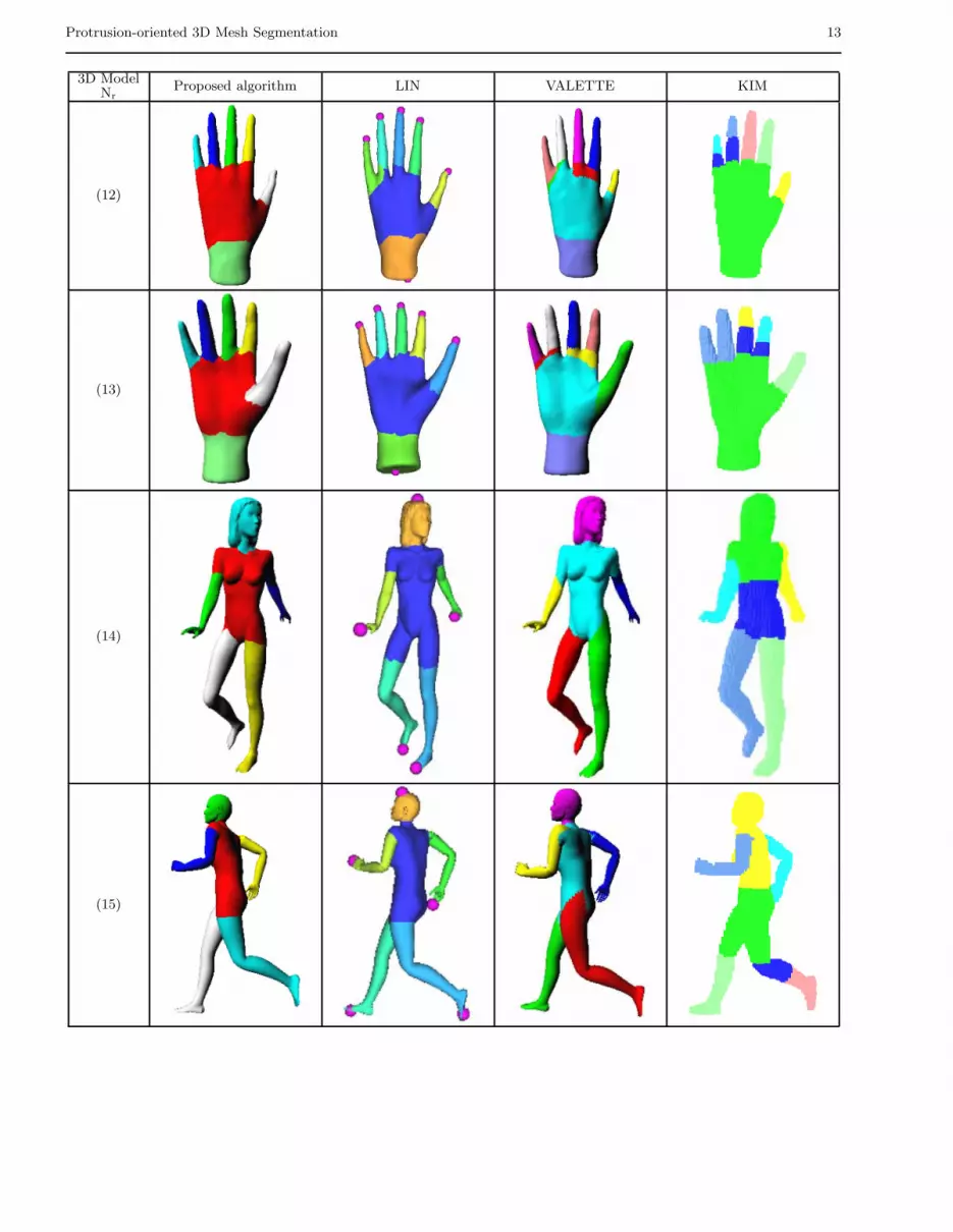
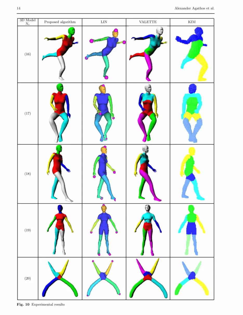
ii. Extracting the “correct” segments. In this cri-terion, the ”correct” segmentation depends on theapplication, the viewer’s perspective and knowledgeof the world which can only be judged qualitativelyby looking at the images of the output of the seg-mentation algorithms. The application that we opt tocouple with the proposed mesh segmentation schemeis 3D model retrieval. Judging from the overall seg-mentation results presented in Fig. 10 it can be seenthat the proposed approach and LIN perform best,i.e. both algorithms segment the meshes in a per-ceptually correct way and it can be observed thatmeshes that belong in the same category, for exampleall humans, are segmented consistently which is veryimportant in the shape retrieval context. VALETTEmanages to extract also perceptually meaningful re-sults but as there are many cases where the segmen-tation among meshes of the same category are notconsistent (eg. models (12)-(13) of Fig. 10) this hasa negative effect in retrieval. KIM manages also toextract perceptually meaningful components but asin VALETTE there are cases where the segmenta-tion among meshes of the same category are non-consistent (e.g. models (7)-(8), (9)-(10), (12)-(13),(14)-(19) of Fig. 10)
10 Alexander Agathos et al.
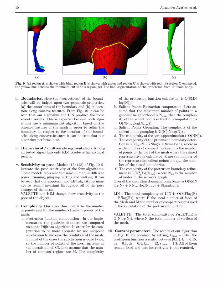
(a) (b) (c)
Fig. 9 (a) region A is shown with blue, region B is shown with green and region C is shown with red, (b) region C enhanced,the yellow line denotes the minimum-cut in this region, (c) The final segmentation of the protrusion from its main body.
iii. Boundaries. Here the “correctness” of the bound-aries will be judged upon two geometric properties,(a) the smoothness of the boundary and (b) its loca-tion along concave features. From Fig. 10 it can beseen that our algorithm and LIN produce the mostsmooth results. This is expected because both algo-rithms use a minimum cut algorithm based on theconcave features of the mesh in order to refine theboundary. In respect to the location of the bound-aries along concave features it can be seen that ouralgorithm performs best.
iv. Hierarchical / multi-scale segmentation.Amongall tested algorithms only KIM produces hierarchicalresults.
v. Sensitivity to pose. Models (15)-(18) of Fig. 10 il-lustrate the pose sensitivity of the four algorithms.These models represent the same human in differentposes : running, jumping, sitting and walking. It canbe seen that our approach and LIN algorithms man-age to remain invariant throughout all of the posechanges of the mesh.VALETTE and KIM though show sensitivity to thepose of the object.
vi. Complexity. Our algorithm : Let N be the numberof points and NS the number of salient points of themesh.a. Protrusion function computation : In our imple-
mentation the geodesic distances are computedusing the Dijkstra algorithm. In order for the com-putation to be more accurate we use midpointsubdivision to increase the resolution of the mesh.In most of the cases the subdivision is done twice,so the number of points of the mesh increase atthe magnitude of 8N. Lets assume that the num-ber of compact regions are M. The complexity
of the protrusion function calculation is O(8MNlog(N)).
b. Salient Points Extraction computation. Lets as-sume that the maximum number of points in ageodesic neighborhood is Nmax then the complex-ity of the salient points extraction computation isO(NNmaxlog(Nmax)).
c. Salient Points Grouping. The complexity of thesalient point grouping is O(N2
S Nlog(N)) .d. The complexity of the core approximation is O(NN2
S).e. The complexity of the protrusion boundary detec-
tion is O(klperN + kNlogN + 8kmnlogn), where mis the number of compact regions, n is the numberof points of the part of the mesh where the refinedrepresentative is calculated, k are the number ofthe representative salient points and lper the num-ber of the closed boundaries.
f. The complexity of the protrusion boundary refine-ment is O(N2
nglog(Nng)) where Nng is the numberof nodes in the network graph.
Overall the algorithm dominant complexity is O(8MNlog(N) + NNmaxlog(Nmax) + 8kmnlogn).
LIN : The total complexity of LIN is O(MFlog(F)+ F2log(F)), where F the total number of faces ofthe Mesh and M the number of compact regions usedin the calculation of the protrusion function.
VALETTE : The total complexity of VALETTE isO(Nlog(N)), where N the total number of vertices ofthe mesh.
vii. Control parameters. The results of our algorithmin Fig. 10 are obtained by setting, tprot = 0.45 (theprotrusion function is scaled between [0,1]), tc = 0.15,d1 = 0.1, d2 = 0.4, lper = 12, rmax = 1.3. All of themremain fixed and user interactivity is not required.

Protrusion-oriented 3D Mesh Segmentation 11
3D ModelNr
Proposed algorithm LIN VALETTE KIM
(1)
(2)
(3)
(4)
(5)

12 Alexander Agathos et al.
3D ModelNr
Proposed algorithm LIN VALETTE KIM
(6)
(7)
(8)
(9)
(10)
(11)
Protrusion-oriented 3D Mesh Segmentation 13
3D ModelNr
Proposed algorithm LIN VALETTE KIM
(12)
(13)
(14)
(15)
14 Alexander Agathos et al.
3D ModelNr
Proposed algorithm LIN VALETTE KIM
(16)
(17)
(18)
(19)
(20)
Fig. 10 Experimental results

Protrusion-oriented 3D Mesh Segmentation 15
Table 1 Computation time for the segmentation of Fig. 103D models
Model Nr. Nr. Vertices Nr. Triangles secs(1) 8504 17004 60(2) 3478 6952 35(3) 12326 24652 68(4) 6689 13374 31(5) 9761 19518 60(6) 7255 14506 38(7) 9492 18980 45(8) 4712 9420 55(9) 7268 14532 35(10) 11312 22620 61(11) 3703 7402 44(12) 7242 14480 34(13) 6607 13210 29(14) 11016 22028 59(15) 5775 11546 52(16) 5766 11528 72(17) 5772 11540 54(18) 5769 11534 55(19) 9509 19014 55(20) 6104 12204 24
In LIN algorithm there exist three parameters thatthe user has to set manually and depend on the coreapproximation and the locales produced by their al-gorithm. Namely the parameters that have to be setby the user are (1) the parameter Δβ which controlsthe extent that the locales overlap with the core ofthe object (2) the parameters Δ+, Δ− which controlthe range of the locales that contain the protrusion’sboundary.It can be seen that our algorithm performs equally orbetter than their results in spite that our parametersremain fixed.
In VALETTE algorithm there exists only one param-eter Pratio which we have set after experimentationto 15% to all of the objects. We have found that thisparameter value produces the best results in their al-gorithm.
In KIM algorithm despite that they set the param-eters fixed, the output is strongly dependent of thevoxelisation resolution. This means that there is aneed for human inspection to correct the resolutionwhen the output is not satisfactory.
In general, there is no any particular geometrical or topo-logical feature that limits the functionality of our seg-mentation methodology for the models used in our ex-perimentation. However, the success of the proposed seg-mentation is bound to the interval [(1− d1) Dcoremin,(1+d2)Dcoremin]. For a meaningful segmentation, the afore-mentioned interval should produce a region that includesthe partitioning boundary. If this is not the case, therewill be a segmentation outcome as in the 3D model ofFig. 11.In Table 1 the time required for segmenting the models
(a) (b) (c)
Fig. 11 (a) The closed boundaries spanning the area[(1− d1) Dcoremin,(1 + d2)Dcoremin], (b) The approximationof the partitioning boundary, (c) Final segmentation
in Fig. 10 is given in seconds. The computation time wascalculated in a Pentium 4, 3GHz PC with 1.5MB mem-ory.Our algorithm has been tested also in terms of robustnesswith respect to noise, i.e. it produces the same segmenta-tion results with different levels of noise. A representativeexample of the proposed mesh segmentation for differentlevels of Gaussian noise is shown in Fig. 12.
In Fig. 13 the core and partitioning boundary approx-imation of the models in Fig. 10 are shown. It can beobserved that the core approximation either cover por-tions of the protrusible parts areas or is very close to theneighboring areas where the real boundary is situated. Itcan also be observed that the approximation of the par-titioning boundary is also effective since it is very closeto the real partitioning boundary.
5 Conclusion
In this paper, a novel 3D mesh segmentation algorithmhas been presented.The novelty of our approach is twofold:i. A novel way to trace the boundary of the protrusion
of the 3D object using closed boundaries constructedwith the aid of a distance function;
ii. A novel algorithm for the core approximation of the3D object is introduced.
The proposed algorithm is capable of segmenting a 3Dobject into perceptually meaningful parts and is pose in-variant. From the experimental results presented it hasbeen shown that it can successfully segment a wide rangeof articulated 3D objects. The evaluation of the proposedalgorithm is addressed in a consistent framework whereina comparison with the state of the art is performed.The algorithm is based on the basic idea that an object

16 Alexander Agathos et al.
(a) (b)
Fig. 12 Segmentation of the ‘camel’ model under different levels of noise (a) SNR = 52dB, (b) SNR = 50dB
can be segmented into its parts if its main body andsalient points are reliably approximated.Our algorithm is capable of producing compatible seg-mentations, for instance the human objects are alwayssegmented into the head, body, arms and legs, thus itcan be successfully applied to applications that requireconsistent segmentations like 3D shape retrieval basedon graph based representations.
Acknowledgements This research was supported by theGreek Secretariat of Research and Technology (PENED “3DGraphics search and retrieval” 03 ED 520).
References
1. Agathos, A., Pratikakis, I., Perantonis, S., Sapidis, N.,Azariadis, P.: 3D Mesh Segmentation Methodologies forCAD applications. Computer-Aided Design and Applica-tion. 4(6), 827-841 (2007)
2. Attene, M., Katz, S., Mortara, M., Patane, G., Spag-nuolo, M., Tal, A.: Mesh segmentation - A compara-tive study. In: IEEE International Conference on ShapeModeling and Applications. IEEE, Matsushima, JAPAN(2006)
3. Attene, M., Falcidieno, B., Spagnuolo, M.: Hierarchi-cal segmentation based on fitting primitives. The VisualComputer. 22(3), 181-193 (2006)
4. Hilaga, M., Shinagawa, Y., Komura, T., Kunii, T.L.:Topology Matching for Full Automatic Similarity Esti-mation of 3D. In: SIGGRAPH, pp. 203-212. ACM, LosAngeles (2001)
5. Hoffman, D., Richards, W.: Parts of recognition. Cogni-tion. 18, 65-96 (1984)
6. Karni, Z., Gotsman, C.: Spectral Compression of MeshGeometry. In: SIGGRAPH, pp. 279-286. ACM, New Or-leans (2000)
7. Katz, S., Tal, A.: Hierarchical Mesh Decomposition Us-ing Fuzzy Clustering and Cuts. ACM Transactions onGraphics. 22(3), 954-961 (2003)
8. Katz, S., Leifman, G., Tal, A.: Mesh Segmentation usingFeature Point and Core Extraction. The Visual Com-puter. 21(8-10), 639-648 (2005)
9. Kim, D. H., Yun, I. D., Lee, S. U.: A new shape decom-position scheme for graph-based representation. PatternRecognition. 38(5), 673-689 (2005)
10. Lee, Y., Lee, S., Shamir A., Cohen-Or, D., Seidel,H.-P.: Mesh Scissoring with Minima Rule and PartSalience. Computer Aided Geometric Design, 22(5), 444-465 (2005)
11. Levy, B., Petitjean, S., Ray, N., Maillot, J.: Least squaresconformal maps for automatic texture atlas generation.ACM Transactions on Graphics. 21(3), 362-371 (2002)
12. Li, X., Toon, T., Tan, T., Huang, Z.:Decomposing poly-gon meshes for interactive applications. In: Proc. of the2001 symposium on Interactive 3D graphics, pp. 35-42,NC, USA 2001
13. Lin, H. S., Liao H. M., Lin, J.: Visual Salience-GuidedMesh Decomposition. IEEE Transactions On Multime-dia. 9(1), 46-57 (2007)
14. Page, D., Koschan, A., Abidi, M.: Perception-based 3Dtriangle mesh segmentation using fast marching water-sheds. In: Proc. Intl. Conf. on Computer Vision and Pat-tern Recognition, pp. 27-32, Wisconsin, USA 2003
15. Shamir, A.: Segmentation and shape extraction of 3Dboundary meshes. In: State-of-the-Art Report, Proceed-ings Eurographics (2006)
16. Shapira L., Shamir, A., Cohen-Or, Lior Shapira, D.: Con-sistent mesh partitioning and skeletonisation using theshape diameter function. The Visual Computer. 24(4),249-259 (2008)
17. Shi, J., Malik, J.: Normalized Cuts and Image Segmen-tation. IEEE Transactions on Pattern Analysis and Ma-chine Intelligence. 22(8), 888-905 (2000)
18. Shlafman, S., Tal, A., Katz, S.: Metamorphosis of poly-hedral surfaces using decomposition. In: Eurographics,pp. 219-228. Eurographics Association, Saarbrcken, Ger-many (2002)

Protrusion-oriented 3D Mesh Segmentation 17
ModelNr.
CorePartitioningBoundaries
ModelNr.
CorePartitioningBoundaries
(1) (2)
(3) (4)
(5) (6)
(7) (8)
(9) (10)
(11) (12)
(13) (14)

18 Alexander Agathos et al.
ModelNr.
CorePartitioningBoundaries
ModelNr.
CorePartitioningBoundaries
(15) (16)
(17) (18)
(19) (20)
Fig. 13 Core approximation and partitioning boundaries of the models of Fig. 10
19. Sukumar, S. R., Page, D. L., Koschan, A. F., Gribok,A. V., Abidi M. A.: Shape Measure for Identifying Per-ceptually Informative Parts of 3D Objects. In: 3D DataProcessing, Visualization and Transmission, pp. 679-686.IEEE, Chapel Hill, NC (2006)
20. Valette, S., Kompatsiaris, I., Strintzis, M. G.: A polygo-nal mesh partitioning algorithm based on protrusion con-quest for perceptual 3D shape description. In: Workshoptowards Semantic Virtual Environments, pp. 68-76. Vil-lars, Switzerland (2005)
21. Wu, K., Levine, M. D.: 3D Part Segmentation Using Sim-ulated Electrical Charge Distributions. Transactions onPattern Analysis and Machine Intelligence. 19(11), 1223-1235 (1997)
22. Zhang, Y., Paik, J., Koschan, A. Abidi, M. A.: A Simpleand Efficient Algorithm for Part Decomposition of 3DTriangulated Models Based on Curvature Analysis. In:International Conference on Image Processing, pp. 273-276. IEEE, Rochester, NY (2002)
23. Zhang, H., Liu, R.: Mesh Segmentation via Recursive andVisually Salient Spectral Cuts. In: Vision, Modeling, andVisualization, pp. 429-436. Erlangen, Germany (2005)
24. Zuckerberger, E., Tal, A., Shlafman, S.: Polyhedral Sur-face Decomposition with Applications. Computers &Graphics. 5, 733-743 (2002)