topological mesh operators
TRANSCRIPT

This article appeared in a journal published by Elsevier. The attachedcopy is furnished to the author for internal non-commercial researchand education use, including for instruction at the authors institution
and sharing with colleagues.
Other uses, including reproduction and distribution, or selling orlicensing copies, or posting to personal, institutional or third party
websites are prohibited.
In most cases authors are permitted to post their version of thearticle (e.g. in Word or Tex form) to their personal website orinstitutional repository. Authors requiring further information
regarding Elsevier’s archiving and manuscript policies areencouraged to visit:
http://www.elsevier.com/copyright

Author's personal copy
Computer Aided Geometric Design 27 (2010) 1–22
Contents lists available at ScienceDirect
Computer Aided Geometric Design
www.elsevier.com/locate/cagd
Topological mesh operators
Thomas Lewiner a, Hélio Lopes a,∗, Esdras Medeiros b, Geovan Tavares a, Luiz Velho b
a Laboratório Matmídia, PUC-Rio, Rio de Janeiro, Brazilb Laboratório VISGRAF, IMPA, Rio de Janeiro, Brazil
a r t i c l e i n f o a b s t r a c t
Article history:Received 2 March 2006Received in revised form 8 February 2008Accepted 22 August 2009Available online 26 August 2009
Keywords:Geometric modelingHandle operatorsStellar operators
In this paper we introduce an unified framework for topological manipulation ontriangulated 2-manifolds with or without boundary. We show that there are two kindsof primitive operators on the underlying meshes: operators that change the topologicalcharacteristic of the mesh and operators that just modify its combinatorial structure. Wepresent such operators and demonstrate that they provide a complete and coherent set ofelementary operations for mesh construction and editing.
© 2009 Elsevier B.V. All rights reserved.
1. Introduction
Triangulated meshes constitute one of the fundamental representations for objects in Computer Graphics and GeometricModeling. They describe the spatial support where attributes of the objects are defined, such as geometry and texture.Moreover, current graphics hardware are optimized for such representations.
Although other representations, such as point sets, are becoming increasingly popular in recent years, polygonal repre-sentations are still prevalent and necessary in one way or another. The main reason is that meshes describe in a convenientpiecewise manner the global space, intrinsic to the object. Point sets, on the other hand, provide only a local description.Indeed, the generation of polygonal meshes from point data is an active area of research.
Two-dimensional surfaces are, arguably, the most common type of object in computer graphics. Moreover, we are ofteninterested in non-degenerate surfaces, i.e. 2D manifolds, since they allow efficient multiresolution representations, compactdata structures and simple geometric approximations. These objects are best represented by combinatorial structures such assimplicial meshes.
Contributions. In this paper we investigate operators to build, unbuild and modify combinatorial two-dimensional manifoldswith or without boundary.
In particular, we introduce an unified framework for primitive operations on combinatorial 2-manifolds with or withoutboundary. This mathematical framework is based on the integration of two fundamental theories: the Handlebody theoryand the Stellar theory.
We further define a complete and sufficient set of operators to change the combinatorial structure, as well as, thetopological characteristic of a polygonal mesh. This computational framework is substantiated by the main theorems of theHandlebody and Stellar theories. These new operators form a complete and coherent set and they not depend on the spacewhere the surface is embedded.
* Corresponding author at: PUC-Rio, Departamento de Matemática, Rua Marquês de São Vicente 225, Gávea, Rio de Janeiro, RJ, Brazil, 22.453-900.E-mail addresses: [email protected] (T. Lewiner), [email protected] (H. Lopes), [email protected] (E. Medeiros), [email protected]
(G. Tavares), [email protected] (L. Velho).
0167-8396/$ – see front matter © 2009 Elsevier B.V. All rights reserved.doi:10.1016/j.cagd.2009.08.004

Author's personal copy
2 T. Lewiner et al. / Computer Aided Geometric Design 27 (2010) 1–22
We finally propose a concise application program interface (API) for the implementation of these operators, give examplesof prototype applications and point out how the framework could be incorporated with advantages in previously knownalgorithms in Geometric Modeling and Computer Graphics.
Paper outline. Section 2 introduces some concepts of combinatorial topology. Section 3 describes previous and relatedworks. Section 4 presents the Handlebody and Stellar theories. Section 5 proposes the complete set of operators for surfacemodeling. Section 6 presents a suitable API for the proposed framework. Section 7 describes example applications improvedby the use of these operators. Finally, Section 8 concludes this work by giving some final remarks and suggestion for futurework.
2. Fundamental concepts
In this section, we present some fundamental concepts of combinatorial topology that will be used on this work.
2.1. Basic topological concepts
A simplex σ p of dimension p (p-simplex, for short) is the convex hull of p + 1 points {v0, . . . , v p}, vi ∈ Rm, in general
position, i.e., the vectors v1 − v0, v2 − v0, . . . , v p − v0 are linearly independent. The points v0, . . . , v p are called the verticesof σ . A face of σ is the convex span of some of the vertices of σ and therefore is also a simplex. The simplices of dimensions2 and 1 will be called, respectively, triangles and edges. If τ is a face of a simplex σ , then τ is said to be incident to σ . Theboundary of a p-simplex σ , denoted by ∂σ , is the collection of all of its faces except σ itself. Two k-simplices σ and ρ ∈ Kare adjacent when σ ∩ ρ �= ∅, and independent otherwise. The valence or degree of a vertex v ∈ K is the number of edgeswhich have v as a vertex, and is denoted by deg(v).
A simplicial complex K is a finite set of simplices containing all their subsimplices such that if ρ and σ belong to K , theneither ρ and σ meet at a subsimplex τ , or ρ and σ are independent. A simplicial complex K is connected if it cannot berepresented as a union of two non-empty disjoint subcomplexes. A component of a complex K is a connected subcomplexthat it is not contained in a larger connected subcomplex of K .
The underlying polyhedron |K | ⊂ Rm corresponds to the union of the simplices in K . A triangle mesh is the underlying
polyhedron of a 2-dimensional simplicial complex.The join σ � τ of independent simplices σ and τ is the simplex whose vertices are those of both σ and τ . The join
of complexes K and L, written K � L, is {σ � τ : σ ∈ K , τ ∈ L} if σ ∈ K and τ ∈ L, σ and τ are independent. Consider asimplicial complex K and σ ∈ K . The local neighborhood of σ is described by the following elements:
• The open star of σ is
star(σ , K ) = {τ ∈ K : σ is a face of τ }.• The star of σ is
star(σ , K ) = {τ ∈ K : τ is a face of an element of star(σ , K )
}.
• The link of σ is
link(σ , K ) = {τ ∈ K : τ and σ are independent and σ � τ ∈ K }.
Definition 1 (Combinatorial surface). A simplicial complex S , |S| ⊂ Rm , is a combinatorial surface if every edge in S is bounding
either one or two triangles and if the link of a vertex in S is homeomorphic either to an interval or to a circle.
The edges in a combinatorial surface S incident to only one face are called boundary edges. Vertices incident to boundaryedges are called boundary vertices. The subcomplex of S of those boundary simplices forms the boundary of S and is denotedby ∂ S . The boundary of a combinatorial surface is a collection of closed curves. The edges and vertices that are not on theboundary are called, respectively, interior edgesand interior vertices.
A combinatorial surface is orientable when it is possible to choose a coherent orientation for all of its simplices, wherecoherent means that two adjacent triangles induce opposite orientations on their common interior edge. The set of faces,edges and vertices of a surface S will be denoted, respectively, by F (S), E(S) and V (S).
2.2. The Euler characteristic of surfaces
The topological setting applied to boundary representation of solids (Baumgart, 1975) has traditionally been the Euler–Poincaré theory, dated from the turn of the XIXth century (Poincaré, 1893). A very important theorem from this theory isthe classification theorem for surfaces, that says:
Theorem 2. Any connected oriented combinatorial surface with boundary is homeomorphic to either a sphere or a connected sum ofg > 0 tori, in any case with some finite number of disks removed. No two of these surfaces are homeomorphic.

Author's personal copy
T. Lewiner et al. / Computer Aided Geometric Design 27 (2010) 1–22 3
The Euler characteristic of a connected combinatorial surface S , denoted by χ(S) with f faces, e edges and v vertices isdefined as
χ(S) = v − e + f .
Poincaré (1893) proved a very important topological invariant for a oriented combinatorial surface with boundary. It saysthat any homeomorphic oriented combinatorial surface has the same Euler characteristic
χ(S) = v − e + f = 2(s − g) − b,
where s is the number of surface connected components, g is the number of genus on the surface, and b is the number ofboundary curves components. The equation above is called the Euler–Poincaré formula.
3. Related works
The representation of a surface by a polygonal mesh is usually made of two parts: the connectivity and the geometry.The connectivity defines neighborhood relations within the surface, while the geometry defines the shape embedding inambient space.
In this paper, we are mainly concerned with the combinatorial structure of a surface. For this reason, we will not addressgeometric issues extensively here. Nonetheless, we observe that the combinatorial representation of a mesh influence theimplementation of geometric operations in non-trivial ways.
Accordingly, we review related work in the area, which fall into three categories: combinatorial data structures; topolog-ical operators; geometric and multiresolution operators.
3.1. Combinatorial data structures
The neighborhood relations within a mesh are encoded by a combinatorial graph that indicates incidence and adja-cency relationships among vertices, edges and faces. The major issue in terms of topological data structures is the trade-offbetween the size of the representation, the execution time of queries; and the flexibility to edit the structure. A generaloverview of data structures for meshes can be found in de Floriani and Hui (2007).
Practically all combinatorial data structures for 2-dimensional manifolds are based on edges or on faces. Edge-based datastructures mainly stores, for each edge, its incident vertices and adjacent edges, while face-based data structures stores, foreach face, its vertices and the adjacent faces.
The classical Winged-Edge (Baumgart, 1975) structure links vertices and faces through the edges, and also includes infor-mation about orientation. Several data structures based on edges have then been proposed. One example is the Quad-Edge(Guibas and Stolfi, 1985) data structure that represents both the primal and dual graphs of the mesh. An important char-acteristic of the Quad-Edge data structure is that it was defined together with an Edge Algebra (see comments in the nextsubsection). Other very significant example is the Half-Edge (Mäntylä, 1988) data structure that decouples the two usesof an edge by adjacent faces and encodes the face orientation by a cycle of half-edges. This structure is very popular inrecent implementations (Boissonnat et al., 2002; Botsch et al., 2002). The Handle-Edge data structure (Castelo et al., 1992;Lage et al., 2005) extends the Half-Edge in order to represent surfaces with boundary. An explicit representation of thesurface boundary will play an important role in the implementation of the operators to be presented in this work.
Some examples of face-based data structure are the one proposed by Higashi et al. (1995), which is designed for robustgeometric computations, and the Corner-Table (Rossignac et al., 2001), which is optimized for memory consumption ratherthan for structure changes. A recently proposed data structure, which is the counterpart of Quad-Edge, is Gems a structurefor d-dimensional triangulations, that stores for each top simplex the list of its incident simplices (Montagner and Stolfi,2006).
All the above data structures were designed to represent only manifold surfaces. Among others, the Radial-Edge (Weiler,1985) and the Non-manifold Indexed Data Structure with Adjacencies (NMIA) (de Floriani and Hui, 2003) are two examples ofdata structures that can represent non-manifold objects, as well. In this paper we adopt an edge-based mesh representation.It is similar to the half-edge, but it is enhanced to support manifolds with boundary. Such data structure shows to be verysuitable for a simple implementation of the proposed mesh operators. However, the topological operators proposed in ourframework can also be implemented using other data structures, such as the Corner-Table.
3.2. Topological operators
Surface modifications are implemented through operators on its mesh representation. These operators can be classifiedaccording to their level of abstraction and their functionality.
Euler operators (Mäntylä, 1988) are low level operators for editing a mesh representation of the boundary of a solid. Theyare based on the Euler–Poincaré theory, which states that the topology of a compact oriented combinatorial surface S withboundary is characterized by its Euler characteristic χ(S) = |V | − |E| + |F |, where |V |, |E| and |F | indicate respectively thenumber of vertices, edges and faces of S . The Euler characteristic classifies compact orientable surfaces according to theEuler formula: χ(S) = 2s − 2g −b, where s is the number of connected components, g is the number of genus (e.g. through

Author's personal copy
4 T. Lewiner et al. / Computer Aided Geometric Design 27 (2010) 1–22
holes, tunnels or handles), and b is the number of boundary curves of the surface. Mäntylä proved that Euler operators forma complete set of modeling primitives for manifold solids (Mäntylä, 1988). That is, every topologically valid polyhedron canbe constructed from an initial polyhedron by a finite sequence of Euler operators. There are two groups of such operations:the make group and the kill group. The main disadvantage of the Euler operators is that, in the process of editing a meshwith these atomic operations, some intermediate results may not represent valid solids. Moreover, the Euler operator thatgenerates a genus, assumes that the 2-manifold being operated is the boundary of a solid in R
3. Therefore, Euler operatorsare usually encapsulated into higher level operators.
Quad-Edge operators are low-level operators based on the Edge Algebra defined by Guibas and Stolfi (1985). Their mainadvantage is conciseness, and they further show that only two atomic operations are sufficient for the construction andmodification of arbitrary topological graphs embedded in two-dimensional manifolds. The Gems data structure has also ansimple algebra associated with it. The Gem Algebra is based on just two topological operators: create and splice. We remarkthat these operators are conceptually equivalent to our handle operators.
The operators proposed in this paper work at a higher-level than the above ones, and as such, could be defined either interms of the Euler or Quad-Edge operators — although this is not necessary. Here we have chosen to define them directly,as atomic operations, since we believe that they provide the right level of abstraction. Moreover, these operators have theadvantage of always maintaining a valid mesh.
3.3. Multiresolution operators
Because of their importance in applications, many high level operators have been proposed to change the resolution ofa mesh. These operators can be used for mesh simplification or mesh refinement. The meshes they operate on can haveregular or irregular connectivity.
Multiresolution operators for regular meshes are usually associated with simplification and subdivision algorithms. Inthis area, the classical operators are the quadrisection for faces (Catmull and Clark, 1978; Loop, 1987) and vertices (Doo andSabin, 1978) (e.g. primal and dual refinement). The drawback of these operators is that they cannot be used for adaptiverefinement without compromising the regularity of the mesh. Recently, two new schemes,
√3 subdivision (Kobbelt, 2000)
and√
2 subdivision (Velho and Zorin, 2001), introduced operators that are suitable for adaptive refinement. These schemesemploy trisection and bisection operators, respectively.
The most popular multiresolution operators for irregular meshes are the edge collapse and its inverse, the edge split. Hoppeet al. (1993) proved that these two operators can be used to transform between any two equivalent simplicial complexes,if respecting the link condition (Edelsbrunner, 2002). Although edge collapse was designed originally in connection withprogressive meshes (Hoppe, 1996), it has also been extensively used in many mesh simplification methods (Garland andHeckbert, 1997).
The operators proposed in this paper have more expressive power than the multiresolution geometric operators discussedabove and can be used to implement them.
3.4. Geometric operators
As we mentioned before, geometric operations are not the focus of this paper. Nonetheless, we would like to brieflydiscuss their relationship with topological operators. Some geometric operations, such as warping deformations, are de-fined only in terms of point-wise information of a shape embedded in the ambient space. Therefore, these operators areindependent of the mesh structure, once the geometry of the point is given.
Other geometric operators, such as the umbrella operator (Taubin, 1995) used in Laplace smoothing, depend on the localgeometry of the surface. There are also operators that associate geometric quantities with elements of the mesh, for exampledifferential properties (Desbrun et al., 2000). These two types of operators need information about the neighborhood of atopological entity, and, thus, they rely on queries about the mesh structure.
The data structure proposed in this paper supports efficient mesh queries and can be augmented with geometric at-tributes associated with different topological elements. Thus, it is suitable for the implementation of geometric operators.
3.5. Overview
In this paper we introduce a complete and minimal set of high-level operators that can be used to change both meshconnectivity and topology. These operators are based on two main theories of combinatorial topology: namely the Handle-body and Stellar theories. They consist of the following atomic operations for:
• Building, unbuilding and changing the topology of a mesh:create(v0, v1, v2)/destroy(f) — generates/eliminates a connected component defined by the triangle (v0, v1, v2)/face f ,respectively;glue(e0, e1)/unglue(e) — joins/splices two pieces of the mesh boundary defined by the pair of edges e0, e1/edge e,respectively.
• Modifying the connectivity and resolution of a mesh:

Author's personal copy
T. Lewiner et al. / Computer Aided Geometric Design 27 (2010) 1–22 5
Fig. 1. 2D handles: H0 = (A0, B0); H1 = (A1, B1); H2 = (A2, B2).
flip(e) — alters the structure of a mesh region defined by two adjacent triangles by swapping their common edge e.split(σ )/flip(σ ) — refines/simplifies the mesh by respectively subdividing/refining either a triangle σ = f or an edgeσ = e.
As we will show in the rest of the paper, these operators can naturally express the algorithms used in geometric modelingand computer graphics applications.
4. Mathematical framework
In this section, we lay out the fundamental concepts of our framework for mesh operations. We distinguish between twokinds of operators on meshes: the ones that change the topology of the mesh, and the one that just alter its combinatorialstructure.
Operators that change the mesh topology globally are based on the Handlebody theory, while operators that alter locallythe combinatorial structure of the mesh are based on the Stellar theory. Both apply on combinatorial surfaces.
4.1. Handlebody theory
The Handlebody theory (Milnor, 1963) refines the Euler–Poincaré theory by bringing several new topological invariantsfor n-dimensional manifolds. The fundamental problem of Handlebody theory is to study the topological changes generatedby handle attachments to a manifold with boundary.
In the surface case, three types of handles are to be defined and they will be distinguished by an index λ that variesfrom 0 to 2. Here, Di denotes the i-dimensional disk and ∂ P denotes the boundary of a set P .
Definition 3. For 2-dimensional manifolds, a handle of index λ, denoted by Hλ , is a pair of topological spaces (Aλ, Bλ) suchthat Bλ ⊂ Aλ , Aλ = Dλ × D2−λ and Bλ = ∂ Dλ × D2−λ .
According to this definition, one can observe that: 1) the set A0 is a 2-disk and B0 is the empty space; 2) the set A1 isa square and B1 is defined to be two of its opposite sides and 3) the set A2 is a 2-disk and B2 is its boundary (see Fig. 1).Observe that Bλ is naturally identified with a subset of the boundary of Aλ , i.e. there is a natural homeomorphism betweenBλ and a subset of ∂ Aλ .
A handle Hλ = (Aλ, Bλ) is attached to a surface S by identifying Bλ with a subset I of ∂ S and glueing Aλ ⊃ Bλ to Salong I .
The next theorem is the main mathematical tool in which the Handlebody theory is based.
Theorem 4 (Handlebody decomposition). For every orientable surface S there is a finite sequence of surfaces {Si}, i = 0..N, such thatS0 = ∅, SN = S and the surface Si is obtained by attaching a handle Hλ = (Aλ, Bλ) to the boundary of Si−1 . This sequence is called ahandlebody decomposition of S.
Fig. 2 illustrates the handlebody decomposition of a torus, S4 = (((S0 + H0) + H1) + H1) + H2.When a handle Hλ = (Aλ, Bλ) is attached to the boundary of Si−1 to obtain Si , a topological change is generated and
such change depends only on the index λ.
Theorem 5. If Si is obtained by attaching the handle Hλ to Si−1 , then χ(Si) = χ(Si−1) + (−1)λ .
As a consequence, the Euler characteristic of a surface S provided with a handlebody decomposition {Si}, i = 0..N , is
χ(S) = |H0| − |H1| + |H2|

Author's personal copy
6 T. Lewiner et al. / Computer Aided Geometric Design 27 (2010) 1–22
Fig. 2. Handlebody decomposition of a torus, S4 = (((S0 + H0) + H1) + H1) + H2.
where |Hk|, k ∈ {0,1,2}, corresponds to the number of handles of type k in {Si}. For example, in the handlebody decom-position of the torus in Fig. 2, there are one handle H0, two handles H1, and one handle H2. The formula above is, then,verified, since the Euler characteristic of a torus is zero. This is a topological invariant introduced by the Handlebody theory.
Handles can be attached to an orientable surface with boundary in such a way to preserve its orientability, i.e., theidentification of Bλ into ∂ S preserves the orientation of S . If one starts with an orientable surface, then after attaching ahandle coherently the surface is again orientable.
We observe that if we keep track of the number of connected components and the number of boundary curves, wecan easily calculate the number of genus on the surface and classify it whenever it is necessary. We will now presenthow to count those two numbers by studying the topological changes caused by a handle attachment that preserves theorientability.
0-Handle. The topological change generated by a handle attachment of index 0 is a creation of a new surface component(see S1 in Fig. 2). This handle attachment increases the Euler characteristic by one.
1-Handle. When the handle H1 is coherently attached to a surface Si , three situations can occur:
(1) The set A1 is attached to disjoint intervals on the same boundary curve component. In this case, the topological changeis the inclusion of a new boundary curve component in the surface (see S2 in Fig. 2).
(2) The set A1 is attached to intervals on different boundary curve components of the same surface component. The topo-logical change is here characterized by the creation of a new genus on the surface. In addition, the number of boundarycurve components decreases (see S3 in Fig. 2).
(3) The set A1 is attached to intervals on different surface components. Here, a boundary curve component and a surfacecomponent is removed.
In these three situations, when a handle H1 is attached coherently to Si−1 to obtain Si , we have χ(Si) = χ(Si−1) − 1.Observe that, all of them alter the number of boundary curves. Moreover, the last one also changes the number of connectedcomponents on the surface.
2-Handle. Handles of index 2 close a boundary curve component (see S4 in Fig. 2).Concluding, there are three types of handles and five different situations in which they can be attached to a boundary
surface.
4.2. Stellar theory
In the previous section, we saw how to change the topology of a manifold. Now, we will see how to manipulate thestructure of a combinatorial surface without modifying its topology, which is the main point of Stellar theory (Alexander,1930; Newman, 1926; Pachner, 1991; Lickorish, 1999).
As we have seen in Section 2.1, the link and the star of a simplex σ provide a combinatorial description of the neighbor-hood of σ . We can use them to define certain changes in a triangle mesh, without modifying essentially (i.e., “topologically”)that neighborhood. That is, we do not want to change the topology of the realization of the surface in R
3. The stellar opera-tions provide a such change. They comprise bistellar moves and stellar subdivision:

Author's personal copy
T. Lewiner et al. / Computer Aided Geometric Design 27 (2010) 1–22 7
Fig. 3. Two-dimensional bistellar moves.
Fig. 4. Two-dimensional stellar subdivision on interior edges.
Fig. 5. Two-dimensional stellar subdivision on boundary edges.
Definition 6. Let K be an n-dimensional simplicial complex. Take an r-simplex σ ∈ K , and an (n − r)-simplex τ /∈ K , suchthat link(σ , K ) = ∂τ . Then, the operation κ(σ , τ ), called bistellar move, consists of changing K by removing σ � ∂τ andinserting ∂σ � τ .
The bistellar moves are atomic operations that make local changes to the neighborhood of an simplex, while maintainingthe integrity of its combinatorial structure. In the case of combinatorial surfaces, there are three types of bistellar moves,for dimσ = 2,1,0, called 2-move, 1-move, and 0-move. They are shown in Fig. 3.
The fundamental result of the Stellar theory is given by the following theorem:
Theorem 7. (See Newman, 1926; Pachner, 1991.) Two combinatorial surfaces are piecewise linearly homeomorphic if and only if theyare bistellar equivalent.
The above result guarantees that bistellar moves can change any triangulation of a closed piecewise linear manifold toany other. A version of this theorem for manifolds with boundary uses all stellar operations, including stellar subdivision(Pachner, 1991).
Definition 8. Let K be a 2-dimensional simplicial complex, take an r-simplex σ ∈ K and a vertex ν in the interior of σ . Theoperation (σ , ν) removes star(σ , K ) and replaces it with ν � ∂σ � link(σ , K ). Such operation is called a stellar subdivision andits inverse (σ , ν)−1 is called a stellar weld.
Note that some of the stellar subdivision and welds are also stellar moves as for example κ(σ ,ν) and κ(ν,σ ) fordimσ = 2 (see the top and bottom rows of Fig. 3).
In dimension 2, this new operation is the stellar subdivision on edges, called 1-split. It is shown in Fig. 4 the interioredge case and in Fig. 5 the boundary edge case.
Stellar subdivision is a very powerful concept and it is the cornerstone of Stellar theory. Here, we will only mentionsome results of the stellar subdivision theory (Alexander, 1930).
Proposition 9. Any stellar move, κ(σ , τ ), is the composition of a stellar subdivision and a weld, namely (τ , ν)−1(σ , ν).
This result can be easily seen through an example, shown in Fig. 6.
Proposition 10. Any stellar operation can be decomposed into a finite sequence of elementary stellar operations on edges.

Author's personal copy
8 T. Lewiner et al. / Computer Aided Geometric Design 27 (2010) 1–22
Fig. 6. A bistellar move on an edge can be decomposed into a subdivision and an weld.
Fig. 7. Handle operator of type 0 (triangle creation).
This result is even stronger than the previous one. It basically allows us to restate the main theorem of Stellar theoryonly in terms of operations on edges. We will use this result to state a simple framework for mesh creation and editionwhich uses only operations on edges, making it particularly suited for implementation on classical data structures.
5. Computational framework
The purpose of this section is to introduce a new set of topological operators based on the concepts of Handlebody andStellar theories. This set includes operators for building/unbuilding meshes and to change the structure and resolution of amesh.
We remark that, although the Handlebody theory can be applied to general combinatorial manifolds, the Stellar theoryis restricted to simplicial complexes. Therefore, from now on, we will focus on triangular meshes. This is not a limitation,since any manifold surface can be triangulated and, in practice, triangular meshes are a common choice in applications.
5.1. Handle operators
5.1.1. Building Handle operatorsThe Handlebody theory presented in Section 4.1 studies the topological changes in a surface caused by a handle attach-
ment. There are three types of handles to build a handlebody decomposition of a surface. From a combinatorial point ofview, we define three types of operators to represent the handle attachments:
• Handle operator of type 0 – This operator creates a new combinatorial surface component with only one triangle (seeFig. 7).
• Handle operator of type 1 – The purpose of this operator is to identify two given boundary edges with no vertices incommon. There are three situations for this group:
Case (a): the boundary edges are on different surfaces. In this case the operator attaches the surfaces and removes oneboundary curve (see Fig. 8(a)).Case (b): the given boundary edges are incident to the same boundary curve. The operator splits the boundary curveinto two different components (see Fig. 8(b)).Case (c): the boundary edges are on different boundary curves on a surface component. It creates a new genus in thesurface and reduce in one the number of boundary curve components of the surface (see Fig. 8(c)).
• Handle operator of type 2 – This operator identifies two given boundary edges with two vertices in common. The operatorcloses one boundary curve component and transform those boundary vertices into two interior vertices (see Fig. 9).
According to the definitions above, we observe that if a Handle operator of type λ is applied to a combinatorial surfaceS1 to obtain S2, then χ(S2) = χ(S1) + (−1)λ . This is a direct consequence of Theorem 5.
One can observe that the Handle operators of type 1 and type 2 identify two boundary edges to make an interior edge.The first is applied when the edges have no vertices in common, and the second when the edges have two vertices incommon. Thus, there is one missing case to consider: when the boundary edges have one vertex in common. So, it issuitable to define the Zip operator, which identifies two boundary edges with one vertex in common. This operator removesone edge and one vertex, then it doesn’t change the Euler characteristic of the surface. Its main purpose is to close thevertex link (see Fig. 10). In fact, such operator can be derived from the building Handle operators together with theirinverse. However, it is very convenient to have a direct implementation of it.

Author's personal copy
T. Lewiner et al. / Computer Aided Geometric Design 27 (2010) 1–22 9
(a) Boundary edges belong to different surfaces
(b) Boundary edges belong to the same boundary curve of a surface
(c) Boundary edges belong to different boundary curves of a surface
Fig. 8. Handle operator of type 1 (joining boundaries).
Boundary edges have two vertices in common
Fig. 9. Handle operator of type 2 (closing boundaries).
Boundary edges have one vertex in common
Fig. 10. Zip operator.
5.1.2. Unbuilding Handle operatorsThere is an inverse operator for each building Handle operator presented. The topological changes caused by their inverse
operation are now described.The unbuilding Handle operator of index zero destroys a triangle. Unbuilding Handle operators of index 1 and index 2
split an interior edge into two boundary edges. There are five cases to consider when splitting an interior edge. Such casesare distinguished according to the number of boundary vertices incident to the interior edge that will be operated, whichcould be 2, 1 or 0. The unbuilding Handle operator of type 1 is used when the incident vertices to the interior edge areboth in the surface boundary. The unbuilding Handle operator of type 2 is applied when the incident vertices of the interioredge are on the interior of the surface. In the last case, when the interior edge has one vertex in the boundary, one shoulduse the inverse Zip operator.
The topological changes caused by an unbuilding Handle operator of index 1 when applied to a given interior edge e,depend on the answer to the following question:
Are the boundary vertices incident to e on different boundary curve components?
If the answer is affirmative then the unbuilding Handle operator will remove one boundary curve component (see theunbuilding operation in Fig. 8(b)). In contrary, the second question has to be answered.
Are those vertices on the same boundary curve component?
When the vertices are incident to the same boundary curve, the unbuilding operation not only will add a new boundarycurve component to the surface but also it will either decrease the genus (see unbuilding of Fig. 8(c)) or disconnect thesurface (see unbuilding of Fig. 8(a)).

Author's personal copy
10 T. Lewiner et al. / Computer Aided Geometric Design 27 (2010) 1–22
Unbuilding operator of index 2 duplicates an interior edge with zero incident boundary vertices. The topological changein this situation is an addition of a new boundary curve to the surface.
The inverse Zip operator (the unzip operator) is applied when the interior edge e has one incident vertex on the bound-ary. It simply duplicates an interior edge and transforms an interior vertex into a boundary vertex.
5.1.3. Algebraic propertiesA surface S is said to be valid if it satisfies the definition of a combinatorial surface. So the Euler–Poincaré formula is a
necessary condition for the validity of the model.
χ(S) = v − e + f = 2(s − g) − b,
where v, e, f ,b, g, and s represent, respectively, the number of vertices, the number of edges, the number of faces, thenumber of boundary curves, the number of genus and the number of connected components on the surface.
Similarly to Braid et al. (1980), we consider a six-dimensional space E6, whose axes are: v, e, f ,b, g, s. The canonical
basis E6 is denoted by B. This consideration allows us to say that the Euler–Poincaré formula can be rewritten in such a
way to represent a hyperplane (five-dimensional subspace) E P on this vector space:
v − e + f − 2(s − g) + b = 0.
It is suitable to define a new basis for this six-dimensional space E6 in such a way that a combination of Handle operators
could be explicitly represented as a vector on the E P hyperplane. This new basis, called the Handle operator basis anddenoted by H, is defined in the following way:
• Handle operator of type 0 ↔ (1,0,0,0,0,0)H .• Handle operator of type 1 (a): boundary edges on different surface components ↔ (0,1,0,0,0,0)H .• Handle operator of type 1 (b): boundary edges on the same boundary component ↔ (0,0,1,0,0,0)H .• Handle operator of type 1 (c): boundary edges on the same surface component but on different boundary curves
↔ (0,0,0,1,0,0)H .• Handle operator of type 2 ↔ (0,0,0,0,1,0)H .
In order to complete the six-dimensional space we can use the perpendicular vector of the Euler–Poincaré hyperplane,which coordinate on the Handle operators basis is (0,0,0,0,0,1)H , and on the canonical basis on the Euclidean space is(1,−1,1,1,2,−2)B .
Now, we would like to change the basis from H to the canonical basis B of E6, whose axis are v, e, f , ∂s, g, s. In this
way, we could obtain the number of cell elements after the application of a combination of Handle operators, or in theinverse way we could obtain the number of Handle operators to be applied to build a surface with a given number of cellelements.
To find the solution of this change of basis problem we need to relate the vectors of the Handle operators basis with thevectors of the basis B. Those relations are expressed as follows:
• Handle operator of type 0: (1,0,0,0,0,0)H ↔ (3,3,1,1,0,1)B .• Handle operator of type 1 (a): (0,1,0,0,0,0)H ↔ (−2,−1,0,−1,0,−1)B .• Handle operator of type 1 (b): (0,0,1,0,0,0)H ↔ (−2,−1,0,1,0,0)B .• Handle operator of type 1 (c): (0,0,0,1,0,0)H ↔ (−2,−1,0,−1,1,0)B .• Handle operator of type 2: (0,0,0,0,1,0)H ↔ (0,−1,0,−1,0,0)B .
We can now introduce the transition matrix Λ as a change of basis matrix from the Handle operators’ base to the baseon the Euclidean space.
Λ =
⎛⎜⎜⎜⎜⎜⎝
3 −2 −2 −2 0 13 −1 −1 −1 −1 −11 0 0 0 0 11 −1 1 −1 −1 10 0 0 1 0 21 −1 0 0 0 −2
⎞⎟⎟⎟⎟⎟⎠
.
So with this matrix we can compute in advance the characteristic of the surface after a combination of the Handle operatorsby just a matrix–vector multiplication:
[v ′]B = Λ[v]H.
For example, a vector (2,1,0,0,0,0)H says that two Handle operators of type 0 and one Handle operator of type 1 (a) hasbeen applied. Multiplying this vector by Λ we obtain (4,5,2,1,0,1)B , which means that the resulted surface has 4 vertices,5 edges, 2 faces, 1 boundary curve, 0 genus, and 1 connected component.

Author's personal copy
T. Lewiner et al. / Computer Aided Geometric Design 27 (2010) 1–22 11
(a) Two uses of Zip operator
(b) One use of Handle operator of type 1(b) and one of type 2
Fig. 11. Obtaining the Zip operator by the use of Handle operators.
In order to compute the number of Handle operators needed to build a surface with boundary, we can use the inversematrix of Λ:
Λ−1 = 1
12
⎛⎜⎜⎜⎜⎜⎝
−1 1 11 −1 −2 2−3 3 9 −3 −6 −6−2 −4 10 4 −4 4−2 2 −2 −2 8 43 −9 15 −3 −6 61 −1 1 1 2 −2
⎞⎟⎟⎟⎟⎟⎠
.
In order to illustrate the use of Λ−1, suppose now that we would like to build a tetrahedron that has 4 vertices, 6 edges,4 faces, no boundary curves and no genus, and 1 connected component. Thus, such surface is represented by the vector(4,6,4,0,0,1)B . If we multiply such vector by Λ−1 we obtain the vector (4,3,1,0,2,0)H . This means that one way toobtain a tetrahedron is to apply 4 Handle operators of type 0, 3 Handle operator of type 1(a), 1 Handle operator of type 1(b) and 2 Handle operators of type 2. It is important to observe that this procedure has to be exercised with care since theunbuilding operators count as −1.
Using this algebraic properties, we could also verify that the Zip operator can be obtained by the application of consec-utive Handle operations. Fig. 11 shows two possible ways to zip two boundary edges:
• One is by the two uses of the Zip operator. The transition caused by two Zip operators on the surface is(−2,−2,0,0,0,0)B , i.e. the resulted surface has −2 vertices and −2 edges than the original one (see Fig. 11(a)).
• An other is by the use of a Handle operators of type 1 (b) and one of type 2. To obtain such transition by the use ofHandle operators, we multiply this vector by the matrix Λ−1 whose result is (0,0,1,0,1,0)H , which is the desiredresult (see Fig. 11(b)).
5.1.4. Remarks on Handle operatorsWith the set of Handle operators presented above one can build and unbuild all kinds of orientable combinatorial
surfaces with or without boundary. The unbuilding Handle operators shall be used to perform cut operations on the surface,while the building Handle operators shall be used to make paste operations. More formally, we could proclaim the followingresults:
Theorem 11. If S is a connected and oriented combinatorial surface with or without boundary, then there is a finite sequence ofunbuilding Handle operators that can completely remove S .
Sketch of the proof. The procedure to destroy the surface is the following: For every interior edge e on S , apply one ofthe unbuilding Handle operators (including the inverse of the Zip operator). Observe that in Section 5.1.2 we study all thepossible cases to apply such operators to an interior edge, and that is always possible to do that. After that, the resultedsurface S ′ has |F (S)| surface components, where each component has only one face. Then, we can apply the unbuildingHandle operator of type 0 to each one destroying all of them. �
If we apply this sequence of operators in the other way round, we obtain the handlebody decomposition of the surface.
Corollary 12. Every orientable combinatorial surface with or without boundary can be created with a finite sequence of buildingHandle operators.
Observe that all Handle operators presented in Sections 5.1.1 and 5.1.2, except the Handle operator of type 0 and its in-verse, are applied to edges. The building operators identify two boundary edges to make an interior edge and the unbuilding

Author's personal copy
12 T. Lewiner et al. / Computer Aided Geometric Design 27 (2010) 1–22
operators split an interior edge to build two boundary edges. In those sections we investigate all the possibilities to pastethat could occur. In all the cases the resulted surface is a valid one.
Theorem 13. Handle operators cannot generate invalid combinatorial surface.
To conclude, from now on we will call the Handle operators presented in this section as low-level Handle operators. Thisis because in Section 6 we will present a suitable API that uses them in a higher level.
5.2. Stellar operators
The Stellar theory presented in Section 4.2 studies structural modifications to the neighborhood of a simplex that do notalter the topology. These modifications are the stellar moves, stellar subdivision and welds. They can be used to change theconnectivity and the resolution of a mesh.
We classify the Stellar operators in terms of their effect in the number of faces, |F |, in the mesh. Accordingly, there arethree groups of operators:
– isolevel;– refinement; and– simplification.
5.2.1. Isolevel Stellar operatorsThe isolevel operators keep the resolution of the mesh at the same level. Thus, they do not change |F |. The operator in
this group is the bistellar 1-move, also called 1-flip (or edge flip). It simply exchanges two existing triangles by two newtriangles. This operator is shown in Fig. 3(b).
The edge flip is a very powerful operator for changing the combinatorics of the mesh structure without altering itsresolution or topology. For this reason, it is the basis of many computational geometry algorithms.
5.2.2. Refinement Stellar operatorsThe refinement operators increase |F |, and thus the resolution of the mesh. The operators in this group are the 2-split
(face split), and 1-split (edge split).The face split replaces one existing triangle with three new triangles, and thus, it increases |F | by 2. This operator is
shown in Fig. 3(a).The edge split has two cases. When the edge is an internal edge, the edge split replaces two existing triangles sharing
that edge with four new triangles. When the edge is a boundary edge, it replaces one existing triangle with two newtriangles. This operator increases |F |, by 1 or 2, depending of whether the edge belongs to the boundary or not. Figs. 4and 5 show the 1-split of an internal and a boundary edge.
5.2.3. Simplification Stellar operatorsThe simplification operators are the inverse of the refinement operators. The inverse of the face split is the face weld,
and the inverse of the edge split is the edge weld, In the case of simplification of an element in the interior of the mesh,the face weld replaces three faces incident in a vertex with one face removing that vertex, and the edge weld replaces thefour faces incident in a vertex with two faces such that the vertex is substituted by one of the two possible edges that givesa triangulation of the region defined by its link.
Observe that weld operations (σ , ν)−1 are specified through a vertex ν , whose star defines the neighborhood to bechanged.
5.2.4. Remarks on Stellar operatorsAt this point it is appropriate to note that Stellar operators can be used as primitives to define other multiresolution
operators.For example, edge collapse and its inverse, vertex split, can be decomposed into a sequence of elementary stellar oper-
ations. This is a natural consequence of Theorem 7. More specifically, the edge collapse is given by a composition of edgeflips and a final edge weld, while the vertex split is given by an edge split composed wit a sequence of edge flips. This isshown in Fig. 12.
We remark that stellar operations are more flexible in general. In the case of edge collapse/vertex split, it is easy tosee that there are many possible sequences of edge flips leading to the final edge weld. Therefore, those edges flips canbe chosen in such a way that the quality of the mesh is improved, for example, those with bad aspect ratios (Vieira et al.,2003). The geometric result of this flips could generate singularities on the geometric polyhedron, in order to avoid that thewell known link condition has to be verified (Edelsbrunner, 2002).

Author's personal copy
T. Lewiner et al. / Computer Aided Geometric Design 27 (2010) 1–22 13
Fig. 12. Decomposition of an edge collapse (top) into an edge swap followed by an edge weld (bottom).
6. Implementation framework
In this section we propose an application program interface (API) for a mesh library based on the Handle and Stellaroperators. To implement such API, we adopt an edge-based data structure similar to the half-edge that supports manifoldswith boundary, although the operators can be defined on any data structure representing the connectivity of the mesh.Such data structure shows to be very suitable for a simple implementation of the proposed mesh operators. Its detaileddescription is on the appendix. All the code and examples are available on the web (Velho et al., 2005),
The API consists of the set of queries, Handle operators, Stellar operators and an additional set of higher-level derivedoperators.
6.1. Queries
The mesh operators need answers of queries and navigation on the mesh structure. The main useful queries are: c =link(s); and c = star(s). Note that they can take as arguments a simplex s of dimension 0 (vertex), 1 (edge) or 2 (face). In ourimplementation, we use only the vertex star, which returns an adjacency iterator object c, called circulator (Mehlhorn et al.,1997). Another useful query, that is directly derived from the star of a vertex is the function degree(v), which is |star(v)|.
We also have the basic operators of the edge algebra (Guibas and Stolfi, 1985): v = org(e) (origin vertex v of a half edgee); f = left(e) (face f to the left of a half edge e); h = sym(e) (symmetric half edge h); and n = lnext(e) (next half edge n on leftface). These functions are trivially computed from edge-based data structures.
In order to have an efficient implementation of the Handle operators, it is important to have an explicit representation ofthe boundary components. Since with that it is possible to identify whether two boundary edges are on the same boundarycomponent or not. For that reason, we also have the query: is_boundary(s), that returns true if the simplex s belongs to themesh boundary.
6.2. Handle operators
The building and unbuilding Handle operators allow cutting and pasting on the surface. They are: f = create(v0, v1, v2)(creates a new triangular face f); destroy(f) (destroys an existing face); glue(e0, e1) (“identifies” two boundary edges to makeone interior edge), and unglue(e) (splits one interior edge to make two boundary edges).
The glue(e0, e1) operator internally decides whether to use a Handle operator of type 1, a Handle operator of type 2or a Zip operator. This decision is done in constant time using our data structure, by simply identifying the boundarycomponents of e0 and e1 and counting how many vertices in common e0 and e1 have. The low level implementation ofthe Handle operator of types 1 and 2 and the Zip operator has constant time complexity, using a union-find data structurefor the boundary.
The unglue(e) operator internally decides whether to use an unbuilding Handle operator of type 1 or type 2 or the unzipoperator. The complexity in the worst case of this decision is done in linear time on the number of faces. Given an interioredge we first have count how many interior vertices are incident to it. If it has two incident interior vertices, we have toapply the unbuilding Handle operator of type 2. In the case it has only one incident interior vertex, we have to apply theunzip operator. Both of them have constant time complexity. Otherwise, we have to apply the unbuilding Handle operatorof type 1, whose complexity is linear in the number of faces, since we have to identify whether the surface component willbe subdivided.
6.3. Stellar operators
The Stellar operators allow changing the resolution and structure of the mesh. They are: flip(e) (swaps the edge e); split(e)(bisects the edge e and its incident faces); split(f) (trisects the face f); weld(v) (inverse of the split operators, which appliesto edges and faces).

Author's personal copy
14 T. Lewiner et al. / Computer Aided Geometric Design 27 (2010) 1–22
Note that flip is only defined for internal edges. In our C++ implementation, split is defined using overload of operators.weld deduces the type operation from the star of the vertex v.
Using our data structure, we can affirm that the operators flip(e), split(e), split(f), and weld(v) have constant time complex-ity.
6.4. Derived, higher-level operators
Although the Handle and Stellar operators described in the previous subsections form a complete set of atomic operatorsto manipulate the combinatorial structure of a mesh, it may be convenient to define some derived mesh operators that areinstrumental in common applications.
These operators can be constructed by a composition of basic Handle or Stellar operators. They encapsulate abstracthigher-level operations on a mesh.
Here we will define the operators attach, detach, and remove, that will be useful in the next section.The operator attach(e, v) augments the mesh by adding to its boundary a new triangle defined by some boundary edge e,
and a new vertex v, as shown in pseudo-code below.
procedure attach(Edge e, Vertex v)Require: e ∈ boundaryf ← create(org(e), org(sym(e)), v)glue(e, f.edge[0])
The operator detach(f) is the inverse of attach, it shrinks the mesh by deleting a triangle from the mesh. It can be a triangleon the boundary or an internal triangle.
procedure detach(Face f)for e ∈ f do
if not is_boundary(e) thenunglue(e)
destroy(f)
The operator remove(v) decreases the resolution of the mesh by eliminating one arbitrary vertex v . In order to be able toapply the stellar weld operator, it first needs to perform some edge swaps to make the degree D of the vertex compatiblewith the desired operation (i.e., in the case of an internal vertex, degree D = 4 for edge weld or degree D = 3 for face weld,and in the case of a boundary vertex, degree D = 3 for edge weld). Note that the selection of edges to be swapped maytake into account the aspect ratio of resulting triangles.
procedure remove(Vertex v, int D)while degree(v) > D do
e ← select_edge(star(v))flip(e)
weld(v)
We could also define an operator insert(v), which would be the inverse of remove. However, this type of operator notonly increases the mesh resolution, but usually also changes the mesh geometry (for example, in the context of meshsubdivision). Because of this dependency, we prefer not defining it here.
7. Applications and examples
Mesh operators embody the fundamental transformations for combinatorial manifolds. Applications that adopt meshesas a surface representation can greatly benefit from our operators, because they provide the correct level of abstraction foralgorithm design and guarantee that the representation is always valid.
In this section we discuss how our framework fits into graphics applications. Below we give examples of the severalalgorithms for geometric modeling that employed some of the concepts presented in this paper. We also describe howthese prototypical applications can fully exploit our mesh operators.
7.1. Mesh construction
Mesh construction is perhaps the most basic geometric modeling application. In this context, advancing front algorithmsconstitute a flexible and principled way to create a mesh representation. This type of algorithm starts with a seed triangleand grows the surface by gluing new triangles to the surface boundary. The Handle operators, create and glue, allow a veryrobust and concise implementation of this algorithm (Medeiros et al., 2003).
Author's personal copy
T. Lewiner et al. / Computer Aided Geometric Design 27 (2010) 1–22 15
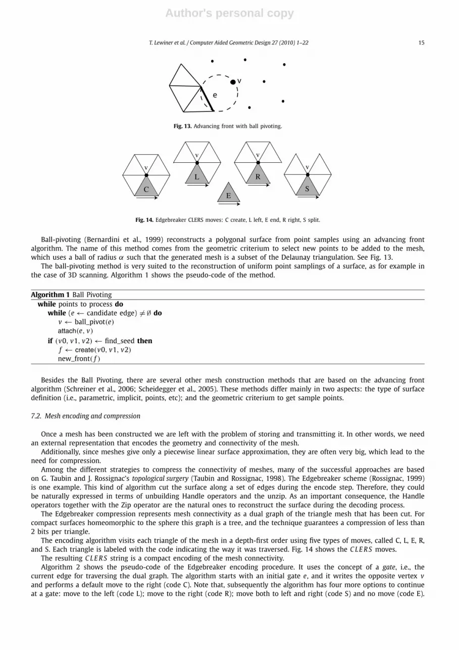
Fig. 13. Advancing front with ball pivoting.
Fig. 14. Edgebreaker CLERS moves: C create, L left, E end, R right, S split.
Ball-pivoting (Bernardini et al., 1999) reconstructs a polygonal surface from point samples using an advancing frontalgorithm. The name of this method comes from the geometric criterium to select new points to be added to the mesh,which uses a ball of radius α such that the generated mesh is a subset of the Delaunay triangulation. See Fig. 13.
The ball-pivoting method is very suited to the reconstruction of uniform point samplings of a surface, as for example inthe case of 3D scanning. Algorithm 1 shows the pseudo-code of the method.
Algorithm 1 Ball Pivotingwhile points to process do
while (e ← candidate edge) �= ∅ dov ← ball_pivot(e)attach(e, v)
if (v0, v1, v2) ← find_seed thenf ← create(v0, v1, v2)
new_front( f )
Besides the Ball Pivoting, there are several other mesh construction methods that are based on the advancing frontalgorithm (Schreiner et al., 2006; Scheidegger et al., 2005). These methods differ mainly in two aspects: the type of surfacedefinition (i.e., parametric, implicit, points, etc); and the geometric criterium to get sample points.
7.2. Mesh encoding and compression
Once a mesh has been constructed we are left with the problem of storing and transmitting it. In other words, we needan external representation that encodes the geometry and connectivity of the mesh.
Additionally, since meshes give only a piecewise linear surface approximation, they are often very big, which lead to theneed for compression.
Among the different strategies to compress the connectivity of meshes, many of the successful approaches are basedon G. Taubin and J. Rossignac’s topological surgery (Taubin and Rossignac, 1998). The Edgebreaker scheme (Rossignac, 1999)is one example. This kind of algorithm cut the surface along a set of edges during the encode step. Therefore, they couldbe naturally expressed in terms of unbuilding Handle operators and the unzip. As an important consequence, the Handleoperators together with the Zip operator are the natural ones to reconstruct the surface during the decoding process.
The Edgebreaker compression represents mesh connectivity as a dual graph of the triangle mesh that has been cut. Forcompact surfaces homeomorphic to the sphere this graph is a tree, and the technique guarantees a compression of less than2 bits per triangle.
The encoding algorithm visits each triangle of the mesh in a depth-first order using five types of moves, called C, L, E, R,and S. Each triangle is labeled with the code indicating the way it was traversed. Fig. 14 shows the C LE R S moves.
The resulting C LE R S string is a compact encoding of the mesh connectivity.Algorithm 2 shows the pseudo-code of the Edgebreaker encoding procedure. It uses the concept of a gate, i.e., the
current edge for traversing the dual graph. The algorithm starts with an initial gate e, and it writes the opposite vertex vand performs a default move to the right (code C). Note that, subsequently the algorithm has four more options to continueat a gate: move to the left (code L); move to the right (code R); move both to left and right (code S) and no move (code E).

Author's personal copy
16 T. Lewiner et al. / Computer Aided Geometric Design 27 (2010) 1–22
In all these cases, the mesh has already been cut, such that the vertex opposite to the gate was previously visited andstored.
Algorithm 2 EdgeBreaker(e)repeat
v ← org(lprev(e))if v not visited then
write geometry(v); mark v as visitedoutput C; e ← lprev(e)
else if right face visited thenif left face visited then
output E; returnelse
output R; e ← lnext(e)else
if left face visited thenoutput L; e ← lprev(e)
elseoutput S; EdgeBreaker(lprev(e)); e ← lnext(e)
until true
We remark that this encoding process is equivalent to unbuilding the mesh. In fact, this could be accomplished by usingthe operation detach after visiting each triangle.
The decoding of a C LE R S string builds the mesh essentially by the reverse of the encoding process. The method Spi-rale Reversi (Isenburg and Snoeyink, 2001), shown in Algorithm 3 does exactly that. It reads the string backwards whileconstructing the mesh.
Observe that the structure of this algorithm is very similar to the one for Advancing Front mesh construction.
Algorithm 3 Spirale Reversie ← initial edgewhile c ← read code do
v ← get_vertex(e, c)if c = C |L|R|S then
attach(e, v)switch (c)case C: e ← lprev(e)case R: e ← lnext(e)case L: e ← lprev(e)case S: pop(lprev(e))
e ← lnext(e)else // c = E
push(e)e = (get_vertex(), get_vertex())create(v, org(e), dest(e))
Edgebreaker can be further extended to encode and decode surfaces with genus (see Lopes et al., 2002). The operatorsof our framework prove to be useful in the design and analysis of algorithms based on topological surgery.
7.3. Mesh refinement and subdivision surfaces
Classical modeling techniques employ polynomial or rational patches, such as B-splines or NURBS, in the geometricdesign of smooth surfaces. In these applications a path is represented by a control polygon.
Subdivision surfaces generalize spline patches to non-regular meshes. In this setting, the surface is the limit of applyinga subdivision scheme to a control polygon. The subdivision scheme is defined by topological rules for mesh refinement andgeometric rules for vertex smoothing.
A simple subdivision scheme for triangle meshes is the√
3 (Kobbelt, 2000). It employs for mesh refinement a combina-tion of the stellar operators face splits and edge flips. The two basic topological rules are shown in Fig. 15.
The√
3 subdivision algorithm consists in the repeated application of the refinement and smoothing rules to a controlmesh. The pseudo-code is given in Algorithm 4, below.
Most refinement methods for subdivision surfaces can be implemented with stellar operators. Velho (2001b) showedthat both primal (Catmull and Clark, 1978) and dual (Doo and Sabin, 1978) schemes can be factorized using edge splits.Other schemes, such as the
√2 subdivision (Velho and Zorin, 2001) also use edge splits.

Author's personal copy
T. Lewiner et al. / Computer Aided Geometric Design 27 (2010) 1–22 17
Fig. 15.√
3 subdivision rules: face split and edge flip.
Fig. 16. Four-face cluster simplification: flips, and weld.
Algorithm 4 sqrt3 Subdivide(M)for face f ∈ M do
v ← split( f )smooth_new_vertex(v)
for all old edges e doflip(e)
for all old vertices o dosmooth_old_vertex(o)
7.4. Mesh simplification and hierarchical structures
In many applications, a surface is densely sampled and approximated by a triangular mesh. This is the case, for example,of 3D scanning and some scientific simulations.
A consequence of such a process is that these meshes are usually very redundant taking more memory space thannecessary for a given approximation accuracy. The solution to this problem is simplification! Mesh simplification algorithmswork by eliminating vertices that do not convey relevant geometric information.
Simplification is essentially an optimization problem: we want to compute a mesh with the minimum number of ele-ments such that a surface is approximated with small error.
The full optimization problem is intractable and most methods employ a “greedy” strategy to find suitable local minima.The basic structure of these methods is as follows: mesh vertices are kept in a priority queue according to some errorfunction. Then, simplification is performed by removing vertices with smallest error until the desired mesh size is reached.
In that way, simplification algorithms can also used to generate approximations of the surface at multiple levels of detailand build a hierarchical structure. This is done by globally simplifying independent regions that completely cover the mesh.
One such algorithm is the four-face cluster simplification (Velho, 2001a) that adopts the quadric error metric (Garlandand Heckbert, 1997) and divides the mesh into regions of four triangles that are simplified using edge weld, after appropri-ate edge flips. See Fig. 16.
The method employs the stellar vertex remove operator, and its pseudo-code is shown in Algorithm 5.
Algorithm 5 Stellar Simplificationassign quadrics to vertices of Mfor all v ∈ M do
compute error E(v)
for j = 1, N doput v ∈ V j into priority queue Qwhile (v ← pop(Q )) �= ∅ do
if v not marked thenremove(v)
locally recompute quadrics and update Q
Any simplification method that is based on edge collapse can be implemented using edge flips and edge splits (Velho,2001a; Vieira et al., 2003). One major advantage of the stellar vertex removal over edge collapse is that it produces meshes

Author's personal copy
18 T. Lewiner et al. / Computer Aided Geometric Design 27 (2010) 1–22
Fig. 17. Histograms of triangle aspect ratio for QSlim and 4-face cluster simplification.
with better quality, since aspect ratio of triangle are taking into account in the optimization. Fig. 17 shows a histogram of amesh simplified from 80k to 40k triangles by both the QSlim and four-face cluster algorithms.
Furthermore, their locality properties make Stellar operators very suitable for creating multiresolution structures. Pro-gressive meshes (Hoppe, 1996) and binary multi-triangulations (Velho and Gomes, 2000) are examples of hierarchical datastructures that can be built with these operators.
7.5. Mesh adaptation
Multiresolution structures constitute the foundation for selecting the appropriate level of detail and adapt a mesh todifferent situations in modeling and visualization, such as display resolution in view dependent rendering.
However, in most applications the level of detail must vary spatially across the mesh and in time as the conditionschange. To resolve this issue, variable resolution adaptation comes into play! The process amounts to coupling an adaptivemechanism on top of a multiresolution structure.
A powerful variable-resolution structure for mesh adaptation is the semi-regular 4–8 mesh (Velho, 2004). It is the two-dimensional version of the n− D Restricted Binary Multi-Triangulation (Mello et al., 2002). The 4–8 mesh has the underlyingstructure of a triangulated quadrangulation (or tri-quad mesh). The properties of this structure makes possible to constructa “virtual” multiresolution, while enforcing that adjacent triangles do not differ by more than one level of resolution. Sucha restriction guarantees a gradual transition in the mesh adaptation.
Another advantage of the adaptive 4–8 mesh is that, thanks to its regular structure, the hierarchy does not need to beexplicitly stored. For this, it is assumed that we are given a base mesh and a function to compute samples of the surfaceover this base domain.
The dynamic 4–8 adaptation mechanism consists in repeatedly coarsening and refining the mesh while conditionschange. For that, two priority queues guide the simplification and subdivision based on some application dependent adap-tation function. Note that this is a conservative strategy, since the mesh is first simplified and only then refined. Thepseudo-code of the method is show in Algorithm 6.
Algorithm 6 Dynamic 4–8 Adaptationread 4–8 base meshinitialize priority queues Q r and Q s
repeatchange mesh and update queueswhile (v ← pop(Q s)) �= ∅ do
if priority(v) < T thenSIMPLIFY(v)
else breakwhile (e ← pop(Q r)) �= ∅ do
if priority(e) > T thenREFINE(e)
else breakuntil (quit)
In order to maintain the mesh invariant that enforces a limit of one-level difference, the concepts of split edge and weldvertex are employed. The split edge is the internal edge of a tri-quad block. As the mesh is refined, neighbor triangles musthave the same split edge to form a block (and therefore, be at the same resolution level). When this is not the case oneof the neighbors must be subdivided first, propagating the resolution restriction. The same reasoning applies in the case ofsimplification for weld vertices. Fig. 18 illustrates the restriction mechanism.
The implementation of the restricted adaptation mechanism for refinement/simplification has a very simple recursive im-plementation, as shown in Algorithm 7. Note that the overall structure of both procedures is essentially the same, revealingthe symmetry of the process.
The adaptive 4–8 mesh can be used in many types of applications where a surface is modified dynamically or even whenthe surface is static by the computation requirements change over time.

Author's personal copy
T. Lewiner et al. / Computer Aided Geometric Design 27 (2010) 1–22 19
(a) test (b) propagation (c) operation
Fig. 18. Dependency propagation for refinement and simplification.
Fig. 19. Adapted meshes generated with a spiraling field at iterations 0, 20, 30, 35, and 63, using 0.012 as time step.
Algorithm 7 Restricted 4–8 Refinement/Simplificationprocedure Refine(Edge e)
for f ∈ star(e) doif f.split_edge() �= e then
Refine(f.split_edge())split(e)
procedure Simplify(Vertex w)repeat
v ← max_level_neighbor(w)if level(v) > level(w) then
Simplify(v)until (degree(v) �= degree(w))weld(w)
One example of such an application is the approximation of deformable surfaces (de Goes et al., 2006). In that case,may be the result of a physical simulation or some other form of procedural animation. Fig. 19 shows the visualizationof a numeric simulation using the level-set method. The surface is the zero-set of a signed distance function representingan interface between two materials. It is a front tracked and evolved by the level-set simulation. For the example in thisfigure we used a spiraling analytical field from Enright et al. (2005), which advects a sphere of radius 0.15 centered at(0.35,0.35,0.35) with velocity:
⎧⎨⎩
u(x, y, z) = 2 sin2(πx) sin(2π y) sin(2π z),
v(x, y, z) = − sin(2πx) sin2(π y) sin(2π z),
w(x, y, z) = − sin(2πx) sin(2π y) sin2(π z).
(1)
Note how the mesh resolution is nicely adapted to the geometric features of the deforming surface. Table 1 gives thetimes for each stage of the computation. We remark that the adaptation is very efficient and the total time is dominated bythe level-set simulation.
Another application that takes advantage of the adaptive 4–8 mesh is the animation of facial expressions (Goldenstein etal., 2005), where the deformation comes from tracking human faces in videos.
Author's personal copy
20 T. Lewiner et al. / Computer Aided Geometric Design 27 (2010) 1–22
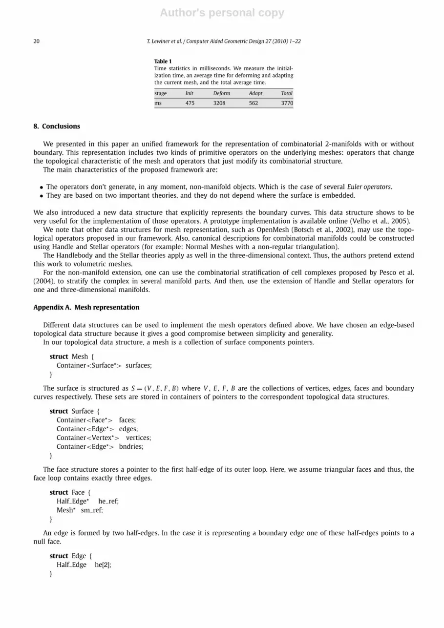
Table 1Time statistics in milliseconds. We measure the initial-ization time, an average time for deforming and adaptingthe current mesh, and the total average time.
stage Init Deform Adapt Total
ms 475 3208 562 3770
8. Conclusions
We presented in this paper an unified framework for the representation of combinatorial 2-manifolds with or withoutboundary. This representation includes two kinds of primitive operators on the underlying meshes: operators that changethe topological characteristic of the mesh and operators that just modify its combinatorial structure.
The main characteristics of the proposed framework are:
• The operators don’t generate, in any moment, non-manifold objects. Which is the case of several Euler operators.• They are based on two important theories, and they do not depend where the surface is embedded.
We also introduced a new data structure that explicitly represents the boundary curves. This data structure shows to bevery useful for the implementation of those operators. A prototype implementation is available online (Velho et al., 2005).
We note that other data structures for mesh representation, such as OpenMesh (Botsch et al., 2002), may use the topo-logical operators proposed in our framework. Also, canonical descriptions for combinatorial manifolds could be constructedusing Handle and Stellar operators (for example: Normal Meshes with a non-regular triangulation).
The Handlebody and the Stellar theories apply as well in the three-dimensional context. Thus, the authors pretend extendthis work to volumetric meshes.
For the non-manifold extension, one can use the combinatorial stratification of cell complexes proposed by Pesco et al.(2004), to stratify the complex in several manifold parts. And then, use the extension of Handle and Stellar operators forone and three-dimensional manifolds.
Appendix A. Mesh representation
Different data structures can be used to implement the mesh operators defined above. We have chosen an edge-basedtopological data structure because it gives a good compromise between simplicity and generality.
In our topological data structure, a mesh is a collection of surface components pointers.
struct Mesh {Container<Surface*> surfaces;
}
The surface is structured as S = (V , E, F , B) where V , E , F , B are the collections of vertices, edges, faces and boundarycurves respectively. These sets are stored in containers of pointers to the correspondent topological data structures.
struct Surface {Container<Face*> faces;Container<Edge*> edges;Container<Vertex*> vertices;Container<Edge*> bndries;
}
The face structure stores a pointer to the first half-edge of its outer loop. Here, we assume triangular faces and thus, theface loop contains exactly three edges.
struct Face {Half Edge* he ref;Mesh* sm ref;
}
An edge is formed by two half-edges. In the case it is representing a boundary edge one of these half-edges points to anull face.
struct Edge {Half Edge he[2];
}

Author's personal copy
T. Lewiner et al. / Computer Aided Geometric Design 27 (2010) 1–22 21
The half-edge is the central topological element of the data structure. It stores a pointer to its initial vertex, a pointer tothe next half-edge in the face loop, and pointers to the edge and face it belongs to. Note that the mate half-edge can beaccessed through the pointer to its parent edge.
struct Half Edge {Vertex* org ref;Half Edge* next ref;Face* f ref;Edge* e ref;
}
The vertex structure stores one pointer to an incident half-edge. In the case of a boundary vertex, this half-edge is partof the boundary curve. This representation makes it trivial to identify if a vertex is on the boundary or is in the interior ofthe surface. Also, it is instrumental not only for the implementation of the vertex star iterator, but also for the boundarycurve iterator. The vertex structure also holds a pointer to vertex geometry.
struct Vertex {Half Edge* star i;Point* p;
}
The point data structure stores a pointer to the vertex. It represents a “bridge” between geometry and topology. It alsostores geometric data of the vertex and can also hold additional data, such as normals, texture and parametric coordinates.
struct Point {Vertex* v;Data* d;
}
These last two data structures separate the roles of points and vertices which are to represent geometry and topology ofthe mesh, respectively. This is a robust approach to compare geometric coincidences between vertices. Surfaces reconstruc-tion is a typical example where this is necessary. Indeed the geometric operations acts on sample points (some may belongto the boundary or not) whereas mesh vertices attach them by handle operations whenever new triangles are created. Seefor example Medeiros et al. (2003).
For a more detailed description of the data structure and to obtain the source code of the Handle and Stellar operatorsusing it see Velho et al. (2005).
References
Alexander, J., 1930. The combinatorial theory of complexes. Ann. Math. 31, 294–322.Baumgart, B.G., 1975. A polyhedron representation for computer vision. AFIPS National Computer Conference 44, 589–596.Bernardini, F., Mittleman, J., Rushmeier, H., Silva, C., Taubin, G., 1999. The ball-pivoting algorithm for surface reconstruction. IEEE Transactions on Visualiza-
tion and Computer Graphics 5 (4), 349–359.Boissonnat, J., Devillers, O., Pion, S., Teillaud, M., Yvinec, M., 2002. Triangulations in CGAL. Comput. Geom. Theory Appl. 22, 5–19, http://www.cgal.org.Botsch, M., Steinberg, S., Bischoff, S., Kobbelt, L., 2002. OpenMesh – a generic and efficient polygon mesh data structure. In: OpenSG Symposium, http://www.
openmesh.org.Braid, I.C., Hillyard, R.C., Stroud, I.A., 1980. Stepwise construction of polyhedra in geometric modeling. In: Brodlie, K.W. (Ed.), Mathematical Methods in
Computer Graphics and Design. Academic Press, pp. 123–141.Castelo, A., Lopes, H., Tavares, G., 1992. Handlebody representation for surfaces and Morse operators. In: Curves and Surfaces in Computer Vision Graphics
III, pp. 270–283.Catmull, E., Clark, J., 1978. Recursively generated B-spline surfaces on arbitrary topological meshes. Comput. Aided Design 10, 350–365.de Floriani, L., Hui, A., 2003. A scalable data structure for three-dimensional non-manifold objects. In: Symposium on Geometry Processing, pp. 72–82.de Floriani, L., Hui, A., 2007. Shape representations based on simplicial and cell complexes. In: Eurographics State-of-The-Art Report.de Goes, F., Bergo, F., Falcao, A., Goldenstein, S., Velho, L., 2006. Adapted dynamic meshes for deformable surfaces. In: Proceedings of SIBGRAPI. October
2006. IEEE Press.Desbrun, M., Meyer, M., Schroder, P., Barr, A., 2000. Discrete differential-geometry operators in nd.Doo, D., Sabin, M., 1978. Behaviour of recursive division surfaces near extraordinary points. Comput. Aided Design 10, 356–360.Edelsbrunner, H., 2002. Geometry and topology for mesh generation. Cambridge.Enright, D., Losasso, F., Fedkiw, R., 2005. A fast and accurate semi-Lagrangian particle level-set method. Computers and Structures 83, 479–490.Garland, M., Heckbert, P.S., 1997. Surface simplification using quadric error metrics. Annual Conference Series Computer Graphics 31, 209–216.Goldenstein, S., Vogler, C., Velho, L., 2005. Adaptive deformable models for graphics and vision. In: Computer Graphics Forum.Guibas, L.J., Stolfi, J., 1985. Primitives for the manipulation of general subdivisions and the computation of Voronoi diagrams. ACM Trans. Graph. 4, 74–123.Higashi, M., Torihara, F., Takeuchi, N., Sata, T., Saitoh, T., Hosaka, M., 1995. Face-based data structure and its application to robust geometric modeling. In:
Solid Modeling and Applications. ACM Press, pp. 235–246.Hoppe, H., 1996. Progressive meshes. In: SIGGRAPH. New Orleans, August 1996, pp. 99–108.Hoppe, H., DeRose, T., Duchamp, T., McDonald, J., Stuetzle, W., 1993. Mesh optimization. Technical report, University of Washington, TR UW CSE 1993-01-01.Isenburg, M., Snoeyink, J., 2001. Spirale reversi: reverse decoding of the edgebreaker encoding. Comput. Geom. Theory Appl. 20 (1–2), 39–52.Kobbelt, L., 2000.
√3 subdivision. In: SIGGRAPH, pp. 103–112.
Lage, M., Lewiner, T., Lopes, H., Velho, L., 2005. CHF: A scalable topological data structure for tetrahedral meshes. In: SIBGRAPI. IEEE, pp. 3349–3356.

Author's personal copy
22 T. Lewiner et al. / Computer Aided Geometric Design 27 (2010) 1–22
Lickorish, W.B.R., 1999. Simplicial moves on complexes and manifolds. In: Proceedings of the Kirbyfest, vol. 2, pp. 299–320.Loop, C., 1987. Smooth subdivision for surfaces based on triangles. Master’s thesis, University of Utah.Lopes, H., Rossignac, J., Safonova, A., Szymczak, A., Tavares, G., 2002. Edgebreaker: A simple compression for surfaces with handles. In: 7th ACM Siggraph
Symposium on Solid Modeling and Application, pp. 289–296.Mäntylä, M., 1988. An Introduction to Solid Modeling. Computer Science Press, Rockville, Maryland.Medeiros, E., Velho, L., Lopes, H., 2003. A topological framework for advancing front triangulations. In: SIBGRAPI. October 2003. IEEE Press, pp. 372–379.Mehlhorn, K., Naher, S., Uhrig, C., 1997. The LEDA platform of combinatorial and geometric computing. In: Automata, Languages and Programming, pp. 7–16.Mello, V., Velho, L., Roma Cavalcanti, P., Silva, C., 2002. A generic programming approach to multiresolution spatial decompositions. In: Visualization and
Mathematics III. Springer Verlag.Milnor, J., 1963. Morse Theory. Annals of Mathematics Study, vol. 51. Princeton University Press.Montagner, A., Stolfi, J., 2006. Gems: A general data structure for d-dimensional triangulations. UNICAMP Technical Report IC-06-16.Newman, M.H.A., 1926. On the foundations of combinatorial analysis situs. Proc. Royal Acad. 29, 610–641.Pachner, U., 1991. PL homeomorphic manifolds are equivalent by elementary shellings. Europ. J. Combinatorics 12, 129–145.Pesco, S., Lopes, H., Tavares, G., 2004. A stratification approach for modeling 2-cell complexes. Computers & Graphics 28 (2), 235–247.Poincaré, H., 1893. Sur la géneralisation d’un théoréme d’euler relatif aux polihédres. C. R. Acad. Sci. Paris 117, 437–464.Rossignac, J., 1999. Edgebreaker: Connectivity compression for triangle meshes. IEEE Transactions on Visualization and Computer Graphics 5 (1), 47–61.Rossignac, J., Safonova, A., Szymczak, A., 2001. 3D compression made simple: Edgebreaker with wrap & zip on a corner-table. In: Proceedings of the 2001
Shape Modeling International Conference, pp. 278–283.Scheidegger, C., Fleishman, S., Silva, C., 2005. Triangulating point set surfaces with bounded error. In: Symposium on Geometry Processing.Schreiner, J., Scheidegger, C., Silva, C., 2006. High-quality extraction of isosurfaces from regular and irregular grids. In: IEEE Transactions on Visualization
and Computer Graphics.Taubin, G., 1995. A signal processing approach to fair surface design. In: SIGGRAPH. August 1995, pp. 351–358.Taubin, G., Rossignac, J., 1998. Geometric compression through topological surgery. ACM Transactions on Graphics 17 (2), 84–115.Velho, L., 2001a. Mesh simplification using four-face clusters. In: International Conference on Shape Modeling and Applications. May 2001. Instituto per la
Matematica Applicata – CNR, IEEE Computer Society.Velho, L., 2001b. Using semi-regular 4–8 meshes for subdivision surfaces. Journal of Graphics Tools 5 (3), 35–47.Velho, L., 2004. A dynamic adaptive mesh library based on stellar operators. Journal of Graphics Tools 9 (2), 1–29.Velho, L., Gomes, J., 2000. Variable resolution 4–k meshes: Concepts and applications. Computer Graphics Forum 19, 195–212.Velho, L., Medeiros, E., Lopes, H., 2005. C++ topological operators for mesh manipulation. http://w3.impa.br/~esdras/tops.Velho, L., Zorin, D., 2001. 4–8 subdivision. Computer-Aided Geometric Design 18 (5), 397–427 (special issue on subdivision techniques).Vieira, A.W., Velho, L., Lopes, H., Tavares, G., Lewiner, T., 2003. Fast stellar mesh simplification. In: SIBGRAPI. October 2003. IEEE Press, pp. 27–34.Weiler, K., 1985. Edge-based data structures for solid modeling in curved-surface environments. IEEE Computer Graphics and Applications 5 (1), 21–40.