technologies for exploration - cern document server
TRANSCRIPT

SP-1254
Contact: ESA Publications Divisionc/o ESTEC, PO Box 299, 2200 AG Noordwijk, The NetherlandsTel. (31) 71 565 3400 - Fax (31) 71 565 5433
SP
-1254Tech
nolo
gies fo
r Explo
ratio
n
Aurora Programme Proposal: Annex DAurora Programme Proposal: Annex D
Technologies for ExplorationTechnologies for Exploration

SP-1254November 2001
Technologies for Exploration
Aurora Programme Proposal: Annex D

Published by: ESA Publications Division
ESTEC, PO Box 299
2200 AG Noordwijk
The Netherlands
Editor/layout: Andrew Wilson
Copyright: © 2001 European Space Agency
ISBN: 92-9092-616-3
ISSN: 0379-6566
Printed in: The Netherlands
Price: €30 / 70 DFl
This report was written by the staff of ESA’s Directorate of Technical and Operational Support.

Technologies for Exploration
Contents
1 Introduction 3
2 Exploration Milestones 3
3 Explorations Missions 3
4 Technology Development and Associated Cost 5
5 Conclusion 6
Annex 1: Automated Guidance, Navigation & Control A1.1and Mission Analysis
Annex 2: Micro-Avionics A2.1Annex 3: Data Processing and Communication Technologies A3.1Annex 4: Entry, Descent and Landing A4.1Annex 5: Crew Aspects of Exploration A5.1Annex 6: In Situ Resource Utilisation A6.1Annex 7: Power A7.1Annex 8: Propulsion A8.1Annex 9: Robotics and Mechanisms A9.1Annex 10: Structures, Materials and Thermal Control A10.1
1
technologies for exploration

Table 1. Exploration Milestones for the Definition of Technology Readiness Requirements.
2005-2010 In situ resource utilisation/life support (ground demonstration)Decision on development of alternative power sourcesSoft landing (Moon, Mars, asteroids)Interplanetary transfer stageIn situ characterisation/resource utilisation test (Moon, Mars, asteroids)In situ exobiology (Mars)Communication network (Mars) / network of satellitesAutonomous rendezvous & docking demonstration flight
2010-2020 Robotic precursor missionsSample return (Mars, asteroids)Knowledge base about humans ‘living in space’Operational Moon mission (In Situ Resource Utilisation & life support)Man-rated soft-landing (Moon)Robotic planetary outpost / deep drillingPlanetary ‘Internet’ capability (planetary relay satellites)In situ resources utilisation (Moon, Mars, asteroids)Closed-cycle life support
2020-2030 Infrastructure operational on martian surfaceMan-rated interplanetary transfer vehiclesMan-rated soft-landing (Mars)Manned mission to Mars Human mobility on planetary surface

1 Introduction
This document provides an assessment of key technology areas for theAurora Programme on Robotic and Human Exploration of the Solar System.Reference phases for exploration are defined within a preliminary scenario.This takes the status of discussion for the longer-term intentions in mannedspaceflight into account and matches it with the known robotic explorationmissions. This scenario is then overlaid with generic exploration missions, assuggested by the ESTEC workshop of April 2001 (see Section 2), in order toestablish the timeframe for the required technology development.
Key technology areas are then defined and an assessment is made of thematurity of these key technologies with respect to the needs. The TechnologyDossiers in the annexes provide a first definition of the correspondingtechnology development and cost plans.
A final overall funding profile is elaborated taking ESA internal (TRP, GSTP)and national activities into account as available. Only additional activitiesspecific to exploration are listed. The resulting funding profile must beconsidered indicative only, especially for the later years, because of thepreliminary nature of the mission scenario and defined exploration mile-stones. For the 3-year preparatory phase of the Aurora Programme, however,choices will have to be made on the most urgent generic technologydevelopments, so that the resulting funding requests are in line with theavailable funding.
2 Exploration Milestones
For the purpose of this document, a sequence of Exploration milestones wasderived on the basis of two sources. Firstly, from recent publications andpress statements it was concluded that an international manned mission toMars might be launched in 2030. Secondly, during the Workshop on Roboticand Human Exploration of the Solar System, held at ESTEC on 3/4 April2001, scientists recommended the following sequence for planetaryexploration: orbiters, landers, in situ robotic exploration, sample return,robotic precursors to manned missions, and manned exploration. This led tothe definition of the reference Exploration Milestones in Table 1.
3 Exploration Missions
The milestones defined above and exploration missions already decided or inan advanced stage of planning set the timeframe for new missions thatmight be chosen within the Aurora Programme. Table 2 (p.4) showsapproved and planned missions, demonstrating the compatibility of theproposed programme with the existing activities.
3
technologies for exploration

4 rS
P-1254
Table 2. Solar System Exploration Missions.

4 Technology Development andAssociated Cost
Once the mission phases are defined in the programme above, technologydevelopment schedules can be tied to it by requiring that a technology for agiven mission must have reached a sufficient level of readiness at the startof the mission’s Phase-B activities.
The elaboration of technology development compatible with the explorationprogramme defined above has also allowed identification of those technologyareas for which work should be conducted immediately. The final selection ofthese areas and their proposed initial funding needs to take the followingfurther criteria into account:
— The available funding through ESA’s Technology Research Programme(TRP), General Support Technology Programme (GSTP) and the GeneralStudies Programme (GSP). For 2001 and 2002, significant funding hasalready been allocated or is foreseen in areas of direct interest toexploration. Particularly relevant from this point of view are the ongoingtechnology development activities of the Agency’s Scientific Programmes,most notably for BepiColombo. Overall, these activities will allow asmooth start in several areas of the Aurora Programme compatible withthe limited funding available. For future years, continuation of theseactivities will be one the tasks of the Aurora Programme.
— The ongoing and planned activities of the national programmes. Theseaspects are dealt with in the Annexes to the best of the Agency’sknowledge and will need to be revisited in the near future in closecooperation with the representatives of the national agencies.
— The generic nature of the technology and its applicability for a range ofexploration missions, in line with the preparatory nature of the first3 years of activities.
The definitions and considerations outlined above lead to the fundingrequirements listed in Table 3 (p.6). The overall level of resources quoted inthe table is generally consistent with the goals of the Aurora Programme.Depending on the final mission selection in some areas, however,significantly higher funding would be needed for optimum utilisation and aconsistent, well-structured enhancement of Europe’s existing industrialcapabilities. In other areas, it is expected that national programmes couldprovide a significant contribution. The proposed funding therefore has to beconsidered as indicative, with some elements still open for differentcontributions. In particular, for the years 2005/2006 it should be noted thatsignificant hardware development is expected to take place and any changein priorities may have a significant impact.
During the preparatory period of the programme, the proposed investmentswill have to be scrutinised while taking into account the available funding
5
technologies for exploration

and the European and national priorities. The prioritisation of the proposeddevelopment plan will have to take into account the potential cooperationwith the international partners in the long term.
5 Conclusion
This document provides an assessment of key technology areas for theAurora Programme on Robotic and Human Exploration of the Solar System. Key technology areas are then defined and an assessment is made of thematurity of these key technologies with respect to the needs. The technologydossiers in the Annexes provide a first definition of corresponding technologydevelopment and cost plans. These documents are intended as a referencefor future work and will have to be further enhanced, taking into account inparticular the ongoing industrial and scientific investigations, beforeconverging on the definition of a European Framework for Exploration.
6
r SP-1254
Table 3. Exploration Initiative: Preliminary Cost Plan (in € million).
Activity 2002 2003 2004 2005 2006
Control and Data Systems 0.5 1.2 2.3 3.8 5.0Micro Avionics 0.2 0.9 2.2 3.0 3.2Data Processing and Communications 0.4 1.5 1.9 3.0 3.8Entry, Descent and Landing 0.9 2.0 2.9 3.5 3.7Crew Aspects of Exploration 0.2 1.8 3.9 4.3 7.8In Situ Resource Utilisation 0.2 0.7 1.3 2.6 2.6Power 0.3 1.0 2.9 5.5 6.7Propulsion 0.4 0.9 1.6 5.5 11.2Robotics and Mechanisms 0.5 2.9 4.6 9.6 17.3Structures, Materials and Thermal Control 0.9 2.3 3.2 5.5 5.5
TOTAL 4.5 15.2 26.8 46.3 66.8

Annex 1
Automated Guidance,
Navigation & Control
and
Mission Analysis

Annex 1 Contents
1 Automated Guidance, Navigation & Control A1.51.1 Introduction A1.51.2 Automated Rendezvous A1.7
1.2.1 Justification A1.81.2.2 Background A1.91.2.3 Planning A1.10
1.3 Entry Guidance, Navigation & Control A1.101.3.1 Justification A1.111.3.2 Background A1.121.3.3 Planning A1.13
1.4 Landing Guidance, Navigation & Control A1.141.4.1 Justification A1.141.4.2 Background A1.151.4.3 Planning A1.17
1.5 Conclusion A1.19
2 Mission Analysis A1.192.1 Introduction A1.192.2 Specific Programme Proposals A1.20
2.2.1 Interplanetary Transfer Optimisation A1.202.2.2 WSB Planetary Arrival Trajectories A1.212.2.3 Advanced Interplanetary Trajectory Navigation A1.22
2.3 Conclusion A1.23
A1.3
annex 1: automated guidance, navigation & control and mission analysis

1 Automated Guidance, Navigation& Control
1.1 IntroductionExploration missions, manned or unmanned, will be characterised by limitedcommunication capabilities owing to long signal delay, limited bandwidthand intermittent opportunities. Automation of onboard processes is thereforerequired to achieve satisfactory response times and handling of anomalies.
Recent years have seen an exponential increase in the use of automationaboard space vehicles, caused by three driving factors: technology availa-bility, the need to reduce operational cost, and the limitations in communic-ations. The foundation for onboard automation lies in the control and datasystems available onboard. Furthering this technology will therefore help toanswer the increased demands of an exploration programme. Thesedemands will initially come from the new capabilities required forunmanned vehicles. But as the mission value/cost increases, the require-ment for higher success rate and the automated handling of contingencieswill be demanded. When man is finally entering the loop, demonstratedflexible and failure-tolerant systems have to be available.
The technology studies in automated guidance & navigation control (GNC)performed in Europe over recent years are too numerous to list individually.There are many areas in which we have unique capabilities or specificstrategic interests, but, focusing on the technologies specific to exploration,the following areas are of particular interest:
— automated rendezvous (system and sensor technologies), as beingdeveloped for ESA’s Automated Transfer Vehicle (ATV);
— launch vehicle trajectory guidance and control, in addition to the Arianefamily of launchers;
— fault-tolerant onboard control and data handling. ESA’s Data Manage-ment System-Russia (DMS-R) has successfully provided the initialcontrol for the International Space Station (ISS);
— man-machine interfaces, where European non-space industry has a lead;— deep space GNC, surpassed only by the US by the number and success of
deep space missions.
Automated rendezvous systems have undergone a long period of develop-ment in Europe, thanks to continuous support from ESA. The capabilitiesdeveloped for ATV constitute the current end product. Beyond the overallautomatic onboard system and its sensory elements of a short-range laserscanner (rendezvous sensor) and differential Global Positioning System (GPS)receivers for the medium range, the unique capabilities in terms of specificrendezvous analysis tools, simulators and dedicated test facilities (e.g. theEuropean Proximity Operations Simulator) must be recognised. The develop-ment is therefore completed as far as the needs of manned low Earth Orbit(LEO) missions. But, if more distant missions are contemplated, the need fornew developments becomes critical.
A1.5
annex 1: automated guidance, navigation & control and mission analysis

Launch vehicle trajectory guidance and control is sufficiently devel-oped for expendable Earth-based launchers, and launcher-specific develop-ment programmes will likely support new developments. However, there areareas in which exploration introduces the necessity for specific capabilities.One large area related to reusability of launchers is reentry technology.There is a certain capability in this field available in Europe through suchprogrammes as Hermes, the Atmospheric Reentry Demonstrator (ARD) andX-38, but nothing unique. Both Russia and the US have superiorcapabilities. It is therefore primarily the strategic importance of futurereusable launchers that demands a drive for mastering this technology.Some developments are therefore expected to be supported by otherprogrammes, but a strong effort will be necessary to address exploration-specific questions.
Fault-tolerant onboard control and data handling was developed for the ISSthrough the DMS-R project. This effort was based on early developments byESA of a SPARC instruction set-based computer core (ERC-32). Develop-ment of cores has continued by adding digital signal processing capabilitiesbased on ADS21020 and generic processor cores (Leon). At some point, thespecific hardware needs of exploration missions will need to be addressed,but the current development in this field is so rapid that a specific effort forexploration is not yet warranted. The emphasis should rather be on thedevelopment of algorithms and architectures for later implementation inhardware.
Man-Machine Interfaces (MMIs) were initially intensively studied forapplications in space through the Hermes/Columbus programmes. Europeanindustry in general has a world-class foundation in human-factorengineering and MMI. This effort should be continued in order to establishearly on which role automation may play in assisting manned exploration,and what the performance requirements are for the automatic systems to bedeveloped.
Deep space GNC is a collective term for the capability that provides theground operational support during deep space missions, navigation forinterplanetary manoeuvring, and systems and equipment for long missionsin harsh environments.
In addition to these areas of traditional capabilities, Europe is in the processof acquiring significant capabilities for soft landing on other planets.Huygens is underway to Titan, Beagle2 is under development for MarsExpress, and Roland is being developed for Rosetta. In addition, CNEScontinues the effort started at ESA for a MarsNet system of landers,potentially followed by participation to a sample-return system. Landing ona planet with an atmosphere is similar to Earth reentry during the initialphases of the entry and hypersonic flight, where deceleration, steering andother GNC aspects are governed by the aerodynamics. This area is thereforecovered by the same reentry technology as identified above for launchers.Landing on a planet (or any target) without an atmosphere is very different,
A1.6
r SP-1254

as retro-propulsive techniques must be used. There are similarities only inthe very final stages of approach and touchdown.
When identifying areas to be covered by the initial 3-year developmentperiod identified in this volumes introduction, we must answer the question:‘Why now, and not in 5 years?’ Many technology areas are in such rapiddevelopment (e.g. computers) that anything new developed now will likely beoutdated in the 15 years leading up to a manned mission. It is thereforerecognised that up-front developments must focus on those technologies withlong lead times and those necessary for precursor missions.
The experience gained from developing ATV’s automated rendezvous is usedfor identifying the long-lead items. Most of the ATV problems were caused bythe interaction between the development of the system concept (strategy,trajectory, etc.) and the new equipment. Initially a system study wasperformed during which equipment specifications were derived. A trade-offof equipment technologies initially selected the most promising for furtherdevelopment, but sometimes during the process a switch to othertechnologies was necessary, the system model had to be refined, and a newset of equipment specifications had to be derived. The development cycle hadto be iterated before a workable baseline could be endorsed for finaldevelopment for ATV. This interaction of system concepts and requiredspecific equipment development is being recognised for the required entryand landing technology areas.
Precursor missions, likely to be automated unmanned vehicles for samplereturn, site survey, site preparation and technology tests, often place morestringent requirements on autonomy and miniaturisation. Notably, earlyexploration missions may be highly similar to today’s science missions, butas the demands on the system rise the invested capital and complexity willincrease. These will demand increases in system robustness andsurvivability – difficult criteria to meet for the long-duration interplanetarymissions. Specific studies to address these problems will therefore be needed.
From the discussion above, four control and data system technology areashave been identified that must be covered specifically by an explorationprogramme:
— Automated Rendezvous— Entry Trajectory, Guidance and Control— Landing Guidance, Navigation & Control
1.2 Automated RendezvousRendezvous technology brings two free-flying space vehicles into contact, butexcludes technologies related to contact dynamics, such as capture, dockingand berthing. An exploration programme needs rendezvous technologies,both for the precursor missions (e.g. sample return) and all of the mannedmissions. Originally conceived as a method of reducing the mass of eachlaunch by dividing complex systems into modules, current manned efforts
A1.7
annex 1: automated guidance, navigation & control and mission analysis

cannot be envisaged without capabilities for crew rescue and logisticsresupply.
There is a distinction between the needs of unmanned precursor missions,which are required to be fully automated, and manned missions, in which acrew can perform the rendezvous manually, maintain a supervisory role, orrelinquish all control to an automated system. For unmanned systems, massand other system resources are typically at a premium in order to reduceoverall mission cost, while for manned systems reliability and robustness arethe focus.
1.2.1 JustificationWhile technologies for manned LEO missions are mature, the specifics ofunmanned scenarios and missions beyond Earth orbit must be addressed.Notably, if the target changes from a circular to an elliptical LEO, or to anorbit about a different body (Moon, Mars) or to deep space (e.g. L2), thedynamics change to such a degree that the overall strategy must be modified.For this reason, the rendezvous needs of exploration missions need specificattention, beyond what is covered in other programmes. Rendezvous forunmanned missions, such as a sample return mission, require improvementsin sensor miniaturisation and performance. Similarly, manned missions toother locations need a replacement for the long- and medium-termnavigation capability that is provided in LEO by GPS. Also, automatedrendezvous systems for LEO applications are not fully autonomous.Monitoring and supervisory control by ground operators increase approachsafety and mission success probability. In all rendezvous operations beyondEarth orbit, supervisory control is limited or impossible. For suchapplications, the onboard system has to be more autonomous, in particularconcerning failure isolation/identification and mission recovery (re-planning)after interruption from a contingency. Previous developments have shownthat these issues need to be addressed at an early stage in order to reach aniterative convergence between the system concept and the equipmentcapabilities.
ATV’s automated rendezvous system is the most advanced in the world.Though the US has long experiences going back to the early 1960s, all USsystems to date have involved man-in-the-loop for controlling the finalapproach. Development of an automated system was begun, but notcompleted. Russia has the longest and deepest experience in automatedrendezvous and docking. System design and technology in use now for theISS is based on 25-30 year-old technology. The Kurs radar-based system is afully autonomous system for LEO applications. It is typically used on theunmanned Progress logistics vehicles for resupplying the ISS. Kurs is verylarge and heavy by today’s standards, and cannot be considered for thesereasons for applications beyond LEO.
Japan’s recent ETS-7 mission demonstrated elements of automaticrendezvous. Though this was an engineering test, it is expected that develop-ment will be continued with the envisaged HII Transfer Vehicle (HTV) for
A1.8
r SP-1254

resupplying the ISS. Its development hinges, however, on the successfulcompletion of the H2A launch vehicle.
We can therefore justify the extension of Europe’s lead in automatedrendezvous by expanding the range of applications through the proposedexploration programme. The foundation of tools and test facilities arealready uniquely available in Europe.
The end goal should be to develop a system applicable to both unmannedsample return from another planet (Moon, Mars and Mercury) and any of theconceived manned exploration missions. ‘Develop’ in the sense of this initial5-year period should be understood as:
— pre-development of the elements needed for the manned systems to thelevel where a harmonised system concept and associated equipment areavailable;
— for unmanned missions to reach a maturity level where demonstrationand early preparation missions can be performed.
1.2.2 BackgroundDevelopment of a rendezvous capability in Europe began in the early 1980sas an enabling technology programme, and continued for Hermes andColumbus. The 3-year Rendezvous and Docking Pre-Development Program(RVD-PDP) laid the foundation in terms of simulation and analysis tools(ROSS) for the onboard GNC system, as well as equipment pre-development(rendezvous sensors, docking mechanism). The next step was the ATVRendezvous Pre-development (ARP), consisting of the development andverification of a realtime onboard system, medium- and short-range sensorsof flight quality, and flight demonstration of the sensor elements. Firstlaunch of the ATV project is expected in 2004.
European companies have therefore already built a significant expertise inthis field. The following table summarises the capabilities of the mostimportant players:
Astrium, Bremen, D System and mission analysis. Control systemdesign (Columbus, RVD-PDP, ARP)
Astrium, Toulouse, F System and mission analysis, camera-typerendezvous sensor. Control system design (Hermes, RVD-PDP, ARP, ATV)
EADS Launch Vehicles, System and mission analysisLes Mureaux, F Control system design (Hermes, ATV)
GMV, Madrid, S System analysisSaab, Gothenburg, S Camera-type rendezvous sensor (not continuedJena Optronic, Laser scanning rendezvous sensor
Jena, D
1.2.3 PlanningFurther development of autonomous rendezvous has to build upon the
A1.9
annex 1: automated guidance, navigation & control and mission analysis

current significant capability. Extensions must initially be sought throughsystems studies on the target orbits, longevity, robustness and massoptimisation. Specific hardware development will then be needed for relativenavigation. This serves a dual purpose: specific developments for unmannedprecursor missions, as well as a pre-development and demonstration effortfor subsequent evolution to robust highly reliable manned systems. Thisway, the specific flight demonstration needs are kept to a minimum.
The first 2 years should lay the foundation through system studies andsimulation tools. The next 2 years concentrate on developing hardware forthe unmanned mission, along with developing higher fidelity simulators andthe initial studies of manned missions. In the final year, the focus shifts toflight demonstration of the techniques for unmanned missions, while thedevelopment of manned systems are ramped up. Hardware development is,at this stage, funded only to the level necessary for supporting thedemonstration missions. The development of man-related systems will haveto continue significantly in the next 5-year cycle, but it can then be based onthe findings of this first period.
On the above basis, the following define an initial set of studies, from whichan expenditure profile for the overall effort was derived (Table A1.1):
— Rendezvous in Non-Circular Orbits,— Relative Navigation for Autonomous Rendezvous beyond Earth Orbit, — Long-Range Rendezvous Sensor for Interplanetary Applications,— Medium-Range Rendezvous Sensor,— Interplanetary Relative Navigation Flight Demonstration,— Automated Contingency Replanning for Rendezvous, — In-Orbit Rendezvous for Sample Return,— Approach to and Rendezvous with Minor Bodies,— Terminal Approach and Capture Strategy and Dynamics.
1.3 Entry Guidance, Navigation and ControlEntry technologies, as identified here, are to a large degree common betweenEarth return (reentry) and the entry and landing on a planet. The onlyplanet with a significant atmosphere of relevance for an initial explorationprogramme is Mars, as neither Venus or the outer planets can support thepresence of humans. The atmospheric pressure on Mars is lower than onEarth, but the weaker gravitational field means that the pressure lapse rateis lower, so the martian atmosphere extends further from the surface.Technologies such as aerobreaking, aerocapture, entry deceleration andvarious atmospheric flight techniques are applicable to both Earth and Marswith many commonalities.
The effort identified here concentrates on the GNC aspects of atmosphericentry and hypersonic flight. Low-speed flight aspects are covered inSection 1.4, while non-GNC aspects such as aerodynamic shape, thermalcontrol and hot structures must be covered by other elements of the explora-tion effort. Within GNC, guidance encompasses trajectory optimisation
A1.10
r SP-1254

techniques to meet system and mission design constraints, as well as pathreplanning in the hypersonic phase for retargeting. Navigation is a uniqueproblem because of the highly accurate surface relative information needed,and the problem of sensing in the high-speed regime when the vehicle inshrouded in a plasma flow. Aerodynamic data acquisition may be consideredas part of the navigation problem. Various aerodynamic means must beconsidered to control the vehicle attitude and trajectory in a mass-efficientmanner. In the latter case, the actuators are not considered as part of thecontrol problem (and so not covered here), but should rather be identifiedand studied in the context of general hot mechanisms.
1.3.1 JustificationWhatever manned exploration mission is contemplated, the crew needs toreturn to Earth. Entry technologies are therefore applicable to any potentialexploration mission. Moreover, if Mars is the target, more specific technologyrequirements have to be addressed. Additionally, related needs will likelyarise for aerocapture and aerobreaking in order to reduce overall missioncost. For unmanned precursors, Europe’s current capability is sufficient forballistic flight systems. However, if more accurate targeting is required, suchas several vehicles landing close to each other for a sample return mission,a new hypersonic steering capability must be developed. Developments inthis field are required if Europe is to have the capability of in situ investi-gation of specific locations.
That European capability is not unique. Both Russia and the US have gained
A1.11
annex 1: automated guidance, navigation & control and mission analysis
Table A1.1: Preliminary Planning for Automated Rendezvous.

long experience from their more than 40 years of competition. Apollo, theSpace Shuttle and Buran all offer steering capabilities better than isavailable in Europe. Japan has been active to a lesser extent, through itsHOPE mini-shuttle development efforts. The justification for Europe’sparticipation is therefore not to be found in a superior capability, but in thestrategic importance of the field. If we embark upon an explorationprogramme, there will likely be room for several players, as demonstrated bythe Crew Return Vehicle cooperation between NASA and ESA. The area islarge enough to encompass several players, and the study and use ofmultiple techniques.
Entry technologies will likely be studied in the context of launchers(reusability) and manned flight to LEO. For exploration missions, the focusis likely to be on capsule shapes entering at relatively high speed.Additionally, the Mars environment demands specific attention for bothunmanned or manned missions.
The goal of the proposed effort for the initial 5-year period should be seen asthe successful development and demonstration of a steerable (re)entrycapability. In its simplest form, this may encompass further development ofthe asymmetric capsule shapes being currently studied, but it may beextended to include winged and/or flexible vehicles such as required for areusable launcher. Demonstration of the developed technology is seen as akey issue.
1.3.2 BackgroundEuropean preeminence in launch vehicle development is exemplified byAriane and studies such as FESTIP (Future European Space TranportationInvestigation Programme) and FLTP (Future Launchers TechnologiesProgramme), which included reuseable vehicles. Europe’s innovations inlauncher trajectory guidance and control are less well-known. The ALTOStool provides a unique flexible and powerful package for handling all kind oflauncher trajectory optimisation problems, ranging from air-breathingmultistage rockets, to various reentry stages. New optimised guidancesystems have been developed for the Ariane family, and other techniqueshave been studied for entry flight of Hermes and Saenger. Control of suchvehicles is often difficult because of the dynamics and interactions betweentrajectory, attitude, environment, system design constraints and vehicleflexibility. Though other countries may have superior flight experience,specific technical solutions studied in Europe may offer the potential forsuperior systems.
ARD is the only demonstration mission in which Europe has flightexperience of active control during (re)entry. Current efforts include thesteerable mini-capsule studied within the CAPREE project, set to developunique guidance and navigation capabilities, and ESA’s involvement in X-38.CAPREE is a TRP technology effort, while X-38 is a large flight demonstra-tion effort in collaboration with NASA that includes ESA participate in GNCissues. As for planetary applications of entry technology, Europe’s efforts so
A1.12
r SP-1254

far are limited to ballistic flights (Huyens, Beagle2), with little or no activeGNC issues.
1.3.3 PlanningInitial efforts must focus on a down-selection of the areas to be covered. Thiswill likely happen in coordination with other development efforts. Once a fewkey areas for the exploration effort have been determined, a pre-development effort similar to that for rendezvous will have to be initiated.An initial guess at these key areas has been made, and is presented below inthe form of individual studies. Again, it serves the sole purpose of identifyingan envelope for the overall effort. These areas include the steering capabilityto target a specific site (focusing on asymmetric capsule shapes), a specificnavigation system in the case of a planetary mission, and air data sensors.
— Hypersonic Precision Steering for Planetary Entry of Capsules— Path Adaptive Reentry Control of Design-Limited Vehicles— Aerocapture Guidance and Control— Atmospheric Flight Control for Planetary Missions— Entry and Hypersonic Flight Technologies— Reentry Flight Demonstration— Hypersonic Flight Data Sensors— Dynamics and Control of Inflatable Heatshield— Navigation for Atmospheric Entry
Starting from the initial down-selection in the first year, the second yearconcentrates on the development of simulation and analysis tools to consoli-
A1.13
annex 1: automated guidance, navigation & control and mission analysis
Table A1.2: Preliminary Planning for Entry GNC.

date requirements on equipment and systems. The second and third yearssee the major developments in preparation for a demonstration flightencompassing as many as possible of the developed technologies. It isexpected that, on the basis of the findings from this pre-development effort,a choice can be made in 2005 of the potential European contributions in thisfield to an exploration mission. Once this is done, the further developmentrequired in the second 5-year cycle is relatively limited. It is, however,mandatory to do this development up front, in order to make the appropriatedecisions in 2005. See Table A1.2.
1.4 Landing Guidance, Navigation & ControlLanding here applies to large and small bodies, with or without anatmosphere, including the Moon, Mars, asteroids and even Earth in the caseof a returning crew or sample (Fig. A1.1). For bodies with a significantatmosphere, landing is differentiated from the entry problem by addressingonly the final low-speed approach and landing phases, in which aerodynamicforces play a lesser role. Retro-propulsive techniques are demanded in theabsence of an atmosphere, but are equally well applicable to landing in anatmosphere. With an atmosphere, additional techniques such as parachutes,parafoil or rotary wings may be contemplated. A fixed-wing solution is lesssuitable because of the need for a prepared ‘runway’.
1.4.1 JustificationAlthough a reference mission has not been defined for the exploration prog-ramme, it is assumed that mastering landing technologies will be required.Hard or semi-hard (e.g. airbag) landings are options for early automatedmissions. As the complexity and value of the landed vehicle increases,however, soft controlled landings with a high success rate and/or an abilityto handle anomalies will be demanded. The estimated 20% mission loss rateduring landing has to be significantly improved.
A1.14
r SP-1254
DeorbitBurn
TrackingUpdate
ApproachPhase
FinalDescent
Lunar OrbitMapping
HomingPhase
Inertial GuidancePhase
Fig. A1.1: Landing GNC requirements for a lunar mission.

Only Russia and the US have performed successful planetary landings. OnlyNASA remains active in the field, with a large array of developments insupport of the planned Mars missions. In some cases, however, the heritagefrom previous projects appears to slow the level of innovation. An example ofthis is the repeated use of the heavy radar-based approach sensor developed30 years ago for Viking, as opposed to newer camera (Fig. A1.2) or laser-based techniques studied in Europe and Japan. Japan does have asignificant development effort in support of missions such as Muses-C andSelene, although a lack of coordination between NASDA and ISAS is slowingdevelopment. Europe, with its developments in support of Rosetta, MarsExpress and BepiColombo, is well positioned to take the lead in this field.
The end goal of the development effort proposed should be perceived asmastering the technologies required to deliver a high value cargo safely tothe surface of another planet. This will allow to consolidate Europe’s positionas an au-par partner to US in this field, and a leader vis-à-vis the rest of theworld. Only in this way can Europe maintain an autonomous capability todeliver and perform experiments on the surface of another planet.Alternatively, the system may be offered as a contribution to a joint mission,as it may be seen as a reasonably isolated system.
1.4.2 BackgroundStudies on planetary landing were initiated in Europe with the preparationactivities for the Rosetta mission proposal. The Comet Approach andLanding System study focused on a radar-based automated descent systemrequiring limited onboard computational resources but with a significantmass impact. A different approach was taken in a follow-up series of studiesfocusing on vision-based systems (COPNAV, HRPBT). From the initial
A1.15
annex 1: automated guidance, navigation & control and mission analysis
Fig. A1.2: Camera-based landing system.

development intending to land the complete Rosetta vehicle on a comet, themission being implemented has a separate orbiter relying on a combinationof optical and NASA Deep Space Network (DSN)-based navigation for cometapproach, and a lander (Roland) without any onboard navigation or controlsystem. The use of a ballistic uncontrolled trajectory down to the surface ispossible in this case only because of the target’s low gravitational field.
While Rosetta relies mostly on optical means to navigate down to thesurface, Huygens will use measurements of deceleration to trigger thesequence of events for descent to the surface of Titan. An onboard range-sensing radar will provide more detailed surface-relative altitude measure-ments during the final phases. While Huygens was not primarily designed tosurvive the landing and perform surface science, the capabilities developedfor the descent system is an important technological achievement.
In the mid-1990’s, a specific interest in lunar missions was identified. Thisled initially to a number of internal ESTEC studies on various lunar landerconcepts (LEDA, ELSPEX and EuroMoon). In parallel, industrial studies(LLS, IVN and VBNL) supported the development of landing technologiesand identified the areas that needed emphasis. In particular, the contract onIntegrated Vision and Navigation for Planetary Exploration (IVN) wasinstrumental in establishing the feasibility of a number of potential landingtechnologies. Advanced hazard-mapping techniques were integrated withonline agents acting as a pilot in order to select the most suitable landingsite in real time (Fig. A1.3). A vision-based navigation system providedground-relative tracking to ensure a soft landing. Although the achieve-ments were impressive, only the feasibility was demonstrated and signifi-cant development is still necessary.
Though little came out of the studies in terms of missions, concepts wereproved and capabilities developed that formed a significant input to thecurrent efforts for defining the BepiColombo Mercury Surface Element. It iswithin this project that these technologies are being furthered today.
A1.16
r SP-1254
Fig. A1.3: The feasibility of automated selection of a landing site has been demonstrated.
Synthetic image Risk map
scale
Confidence map

Beagle2 forms a development branch much on its own, separate from the ESAefforts, largely because of the funding scheme. Through recent changes in theproject set-up, this effort is becoming more coordinated with the others.
The following is a summary of landing technology development efforts so farin Europe:
Comet Approach and Landing System Officine Galileo I(CALS) Selenia Spazio I1988-90 FIAR I
NFT NAME Space NCNR-IAS IU. of Roma I
Lunar Landing System Study Matra Marconi Space F(LLS) GMV SIntegrated Vision and Navigation for Aerospatiale FPlanetary Exploration (IVN) Fokker NL
INRIA FDIST IJoR A
High Resolution Planetary Body JoR A3D Model of Terrain (HRPBT)1990-95Vision Based Navigation for Moon JoR ALanding (VBNL)Huygens Landing System DevelopmentHuygens Descent Radar Ylinen FINBeagle2 Landing System DevelopmentRoland Landing System Development(COPNAV)
Lander technologies are to a large part specific to planetary missions. Thereare, however, cases in which relevant technology has a broader range ofapplications. One such is the development of a smart camera system forlander navigation through interest-point tracking, currently beingconsidered under ESA’s space science core technology programme. Thiscamera and its related components have potential applications on Earthobservation and manned spaceflight missions, as well as specific terrestrialindustrial processes.
1.4.3 PlanningThe capability currently available or under development in Europe focusesprimarily on the delivery of relatively small hard-landing packages. Oncemore valuable payload is involved, methods of trajectory control (throttle-able engine), hazard avoidance, abort scenarios and improved navigationmethods must be developed. As identified in Section 2 for rendezvous anddocking, this will require an iterative development of strategies, systemsand associated equipment. The following is therefore a preliminary list of
A1.17
annex 1: automated guidance, navigation & control and mission analysis

conceivable studies necessary in order to reach the desired level ofmaturity:
— Hazard-Avoidance for Automated Landing of High-Value Cargo— Autonomous Piloting of Landers— Path Adaptive Terminal Control with Retargeting— Precision Landing System Study— Navigation for Return to Base Missions— Micro ElectroMechanical System (MEMS) Inertial Measurement Units
for Descent and Landing— Vehicle Touchdown Control— Vision-Based Absolute Navigation above Planetary Terrain— Abort Strategies for High-Value Cargo— Controlled Planetary Landing System Study— Planetary Landing Demonstration Flight (Selene type)
The development process suggested in this funding profile corresponds to aninitial system and technology concept study phase along with the early devel-opment of the analysis tools (1.5 years). Following is a period of system andequipment pre-development, in order to consolidate the expected perform-ances. The next step is a demonstration effort through flight tests of specifickey areas. This demonstration effort is expected to bridge over into the next5-year period. It is also expected that mission-specific developments will haveto follow in the next 5-year cycle, but the pre-developments proposed hereshould significantly ameliorate the involved risk. See Table A1.3.
A1.18
r SP-1254
Table A1.3: Preliminary Planning for Landing GNC.

1.5 ConclusionThree areas for technology development in support of Solar System explora-tion have been identified. The overall suggested funding profile for the fiveinitial years is given in Table A1.4 on a 2001 price basis.
In addition to the coverage of the above-defined technology areas, it isstrongly recommended to embark on a precursor mission for the develop-ment, testing and demonstration of a soft-landing capability. Such a missionshould test as many soft-landing technologies as possible: autonomy, hazardavoidance, propulsion, piloting, range and rate sensors, operational pro-cedures, design principles and tools, touchdown systems, control duringground contact, energy absorption systems etc. Many of these technologiescannot be tested to a satisfactory level on Earth. The Moon forms a naturalnearby target to perform such tests at a reasonable cost. If no specificpayload requirements are imposed, it is believed that such a test vehicle canbe developed for less than €50 million once the needed technologies areindividually funded. Launch should be targeted for about 2006. Analternative would be to participate in the Japanese Selene missions, but thereadiness in NASDA for cooperation is perceived as low at this stage.
In addition to the above-defined Automated GNC activities, a specificpropulsion need has been identified. To perform a precision landing on aplanetary surface, some method of throttling the applied thrust is necessaryin order to compensate for downrange dispersions. None of our currentlyplanned landing missions has such a trajectory-correction capability. In theinternal studies performed, the problem was circumvented by the use ofmultiple thrusters operated in an off-modulated manner. This is possibleonly for relatively small landers (as in the above proposed demonstratormission) using small thrusters. A throttleable thruster is therefore needed,whose overall thrust level depends on the mass of the payload to bedelivered. Which propulsion technology is used (storable or cryogenic) isimmaterial, as long as a minimum throttle ratio of ±20% is guaranteed.
2 Mission Analysis
2.1 IntroductionMissions in the Solar System are challenging in terms of their high orbitalenergy requirement. A traditional way of gaining energy during the mission,
A1.19
annex 1: automated guidance, navigation & control and mission analysis
Table A1.4: GNC Preliminary Funding Profile (in € million).
Activity 2002 2003 2004 2005 2006
Automated rendezvous 0.1 0.2 0.3 0.6 1.5Entry trajectory, guidance and control 0.2 0.5 1.0 1.6 1.5Landing guidance, navigation & control 0.2 0.5 1.0 1.6 2.0

thereby reducing the launch energy requirement, is to include gravity-assistmanoeuvres with planets during transfer. This is a popular procedure,applied successfully during many interplanetary missions. However, ways offinding the most efficient sequence of gravity-assists are still not trivial,particularly if impulsive or low-thrust mid-course manoeuvres are included.
Gravity-assist manoeuvres are not the only way of borrowing orbital energyfrom the massive bodies of the Solar System. A more subtle method is tomake use of the Weak Stability Boundary (WSB) properties in the vicinity ofthe Lagrange points of a Sun-planet or planet-moon system. WSB trajec-tories allow a reduction of planetary escape or arrival energy. It is proposedhere to further investigate the benefit of such procedures.
Finally, defining optimum trajectories for reaching a given target in theSolar System does not guarantee that such trajectories can actually be flown.The navigation along the trajectories needs to be assessed in order to verifythat the gravity-assist manoeuvres can be performed and that the finaltarget can be reached with the desired precision. This is particularly crucialwith exotic trajectories including WSB, low-thrust arcs and aerobrakingduring gravity-assist.
2.1 Specific Programme Proposals2.2.1 Interplanetary Transfer Optimisation2.2.1.1 Background and JustificationTo find an optimum trajectory from Earth to a planet or a specific orbit in theSolar System is not trivial. An optimum trajectory means that the initialEarth escape velocity (launch energy) is within reach of cost-effectivelaunchers and the sum of the mid-course and final manoeuvres does not
A1.20
r SP-1254
Fig. A1.4: Ariane-5 ECB estimated mass performance in terms of C3 (square of escapevelocity) and declination of the asymptote.
excessively penalise the spacecraft’s propellant budget. Such optimumtrajectories usually involve intermediate planetary Gravity Assist Manoeu-vres (GAMs). They provide velocity increments during transfer at almost nocost, but finding their proper sequence is still an art rather than a science.Once an adequate GAM sequence is found, there are procedures available foroptimising the trajectory to any desired accuracy. The main problem is tofind a suitable initial sequence.
2.2.1.2 PlanningDefining a suitable sequence of GAMs for a given mission requires solving aglobal optimisation problem. Algorithms expected to handle the problemwith good chance of success include Genetic Algorithms. These have beenapplied successfully in the search for WSB trajectories and they may be agood candidate for finding suitable GAM sequences. An initial effort in thisdirection is therefore desirable.
Once a suitable GAM sequence is found with the help of Genetic Algorithms,it is expected that the same method may be used to refine the trajectory byreplacing the procedure’s rough analytical approximation (linked conics) bymore refined models (patched conics or matched asymptotic expansions).This should be done in a second phase.
These methods are to be applied to the simple case of GAMs separated bycoast arcs and also to cases when mid-course manoeuvres, impulsive or low-thrust are included. In a final refinement of these methods, powered swing-bys (impulsive, low-thrust or aerobraking) should also be included.
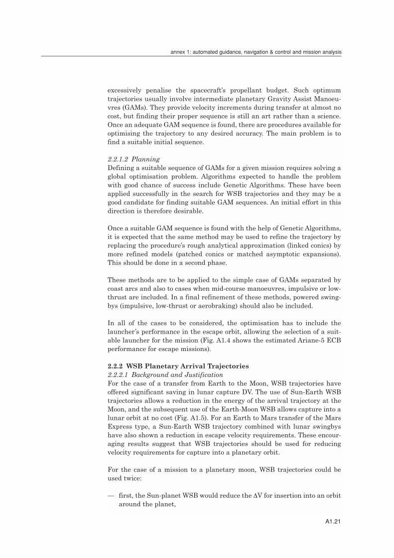
In all of the cases to be considered, the optimisation has to include thelauncher’s performance in the escape orbit, allowing the selection of a suit-able launcher for the mission (Fig. A1.4 shows the estimated Ariane-5 ECBperformance for escape missions).
2.2.2 WSB Planetary Arrival Trajectories2.2.2.1 Background and JustificationFor the case of a transfer from Earth to the Moon, WSB trajectories haveoffered significant saving in lunar capture DV. The use of Sun-Earth WSBtrajectories allows a reduction in the energy of the arrival trajectory at theMoon, and the subsequent use of the Earth-Moon WSB allows capture into alunar orbit at no cost (Fig. A1.5). For an Earth to Mars transfer of the MarsExpress type, a Sun-Earth WSB trajectory combined with lunar swingbyshave also shown a reduction in escape velocity requirements. These encour-aging results suggest that WSB trajectories should be used for reducingvelocity requirements for capture into a planetary orbit.
For the case of a mission to a planetary moon, WSB trajectories could beused twice:
— first, the Sun-planet WSB would reduce the ∆V for insertion into an orbitaround the planet,
A1.21
annex 1: automated guidance, navigation & control and mission analysis

— then, the planet-moon WSB would allow easy capture into an orbitaround the moon.
These two WSB manoeuvres could be combined with moon swingbys.
2.2.2.2 PlanningThe benefit of using WSB trajectories for reducing capture ∆V for insertioninto an orbit around a planet is to be assessed by analysing practical cases:
— arrival at a terrestrial planet (typically Mercury),— arrival at a giant planet (typically Jupiter).
For the Jupiter arrival, combination with swingbys around the moons shouldbe investigated. Then, the case of a moon as a target body should beinvestigated, where the planet-moon WSB is used, possibly combined withswingbys with other moons.
Finally, a low-thrust mission to Jupiter using solar electric propulsion shouldbe analysed. Although solar power is not efficient for outer Solar Systemmissions, it is still the only alternative for Europe to cover the energy needof a Jupiter mission. As very large solar arrays are needed for covering theenergy requirements on orbit around Jupiter, it is natural to use these solararrays as a source of propulsion power during the cruise phase. In this case,a problem is encountered at Jupiter arrival, where a large velocity impulseis needed for capture, involving chemical propulsion and constraining thesolar arrays to be retracted (a risky operation). However, if WSB techniquesallow the arrival ∆V to be small enough to be performed with a low-thrustengine, then the entire mission can be accomplished at low thrust, withoutany need for chemical propulsion. This would make the mission extremelyefficient. The feasibility of such a mission should be analysed.
2.2.3 Advanced Interplanetary Trajectory Navigation2.2.3.1 Background and JustificationClassical navigation for interplanetary missions involving long coast arcs,impulsive mid-course manoeuvres and planetary gravity-assist manoeuvresis well mastered by ESA, as demonstrated by Giotto. However, modern techni-ques for travelling in the Solar System make use of exotic techniques such as:
— solar electric propulsion resulting in long low-thrust arcs,— planetary gravity-assist manoeuvres involving powered swingbys
(impulsive or low-thrust) and aerobraking,— WSB trajectories.
They all pose new challenges in navigation methods and need to beinvestigated.
2.2.3.2 PlanningNavigation including low-thrust manoeuvres combined with planetarygravity-assist is to be investigated first. It is urgently required not only for
A1.22
r SP-1254

the Aurora Programme but also for some ESA-approved missions such asSMART-1 and BepiColombo.
In a second phase, particular attention should be given to the inclusion of man-oeuvres during gravity-assist (powered swingbys), which can be of three types:— impulsive (chemical propulsion) during swingby,— low-thrust (electric propulsion) before, during and after swingby,— aerobraking during swingby for planets with an atmosphere.
The investigation should first concentrate on the feasibility of performingsuch a manoeuvre successfully. In other words, can navigation be preciseenough to create a swingby having the desired effect on the orbitalparameters?
Finally, navigation along WSB trajectories proposed for capture into an orbitaround a planet or a natural satellite Should be investigated. For each classof trajectories, ground-based and autonomous navigation should beconsidered.
2.3 ConclusionThree areas of improvement in support of mission analysis for Solar Systemexploration mission have been identified:
— optimisation of interplanetary transfer trajectories, including gravity-assist manoeuvres (unpowered, powered or with aerobraking) and low-thrust arcs,
— the use of WSB trajectories for planetary capture,— advanced interplanetary trajectory navigation.
These topics can be covered by performing corresponding studies with a totalfunding of the order of €0.4 million.
A1.23
annex 1: automated guidance, navigation & control and mission analysis
Fig. A1.5: WSB trajectory from Earth to Moon.
Satellite orbitMoon orbit

Annex 2
Micro-Avionics

A2.3
annex 2: micro-avionics
Annex 2 Contents
1 Introduction A2.51.1 Background A2.51.2 System Issues A2.51.3 Logical Steps A2.6
2 Technology Item Description A2.92.1 Micro-electronics A2.92.2 Main Building Blocks A2.9
3 Status A2.123.1 Micro-electronics A2.123.2 Avionics Building Blocks A2.123.3 Avionics Systems A2.13
4 European Technology Programmes A2.13
5 Justification and Rationale A2.14
6 Technology Roadmap (Next 30 Years) A2.15
7 Technology Programme Proposal A2.157.1 SOI-CMOS Technology Validation A2.167.2 Aurora Avionics Architecture A2.167.3 Aurora Avionics Main Building Blocks asa ‘System on a Chip’ A2.177.4 Spacecraft Manager Software Kernel A2.177.5 Reconfigurable Hardware: Large-Scale Reprogrammable A2.18
FPGAs7.6 Reconfigurable System: Highly Dependable Computing on A2.18
ULSIC7.7 Extreme Environment Technology Watch and Assessment A2.18

1 Introduction
1.1 BackgroundThe term ‘avionics’ covers the hardware and software elements that, on anaircraft or spacecraft, provide the data acquisition and processing, thecommand distribution, transducers (sensors and actuators), onboard datacommunications and ‘flight segment’ of the space link (ground-spacecommunications). This set of informatics/telematics equipment constitutesthe brain and nervous system of the spacecraft and is critically important tothe mission success.
The term ‘micro’ denotes the need for mass optimisation. The imperative isamplified by an order of magnitude if the mission includes a lander, and bya further order of magnitude if it includes sample return. It is expected thatthe miniaturisation will build upon the constant progress in micro-electronics. However, to be effective at system level, the miniaturisation hasto be understood as a system-level optimisation process, which includesconsiderations proper to the internal architecture of the avionics system aswell as its position in the overall spacecraft system.
1.2 System IssuesDecoupling of the functional/performance specifications from the implementationOn a standard spacecraft, the avionics implement the command and datamanagement functions and the attitude and orbit control/guidancenavigation control function. A key requirement for systems on deep-spaceprobes, where each kilogram has to be justified, is to achieve a gooddecoupling of the avionics’ final implementation from the performance andfunctional specifications of the different subsystems to be supported, inparticular the command and data management and the attitude/orbit andguidance/navigation control. The reason is that the design of the avionicsshould optimise the implementation based on objective criteria of mass,power, volume, reliability etc. while meeting the mission objectives andrelated constraints (operations, environment).
Global optimisation versus local optimisation The avionics already constitute a ‘system’ connected to different elements ofthe spacecraft: other subsystems and payloads. The miniaturisation efforthas to be consistent end to end. When looking to existing state of the artavionics systems, it is clear that a drastic miniaturisation of the centralelectronics alone will have little impact, from a system perspective, if it is notperformed in a ‘system’ approach that includes the minimisation of harnessand connectors by setting up smart sensors and interfaces and by using asensor or field bus.
Impact on other subsystems: power/energy – thermalThe mass or volume gain at the avionics level has to be balanced in a systemapproach. If the mass reduction is not accompanied by a power reduction, thebenefit at system level will be reduced by retaining large batteries and largesolar panels (Rosetta). If miniaturisation is not accompanied by a power
A2.5
annex 2: micro-avionics

reduction, thermal dissipation problems will occur with solutions (activecooling, heat pipes) that may hamper the initial benefit. At mission level, theemphasis is often on energy minimisation rather than power minimisation,but the instantaneous peak power is of more concern for the powersubsystem design. For example, a power peak cannot be avoided on a MarsLander to power the transmitter during a communications window. Fordeep-space probes with long communications delays to Earth, it calls forsome autonomous adaptability of the resources management system to thelocal conditions.
EnvironmentAnother concern is the environment met by the spacecraft at other planets,especially if there are surface or subsurface operations:
Mercury : 180ºC (poles), 270ºC (equator)Venus: 400ºC / 90 barMars: daily temperature cycling from –120ºC to 40ºC (winter), –60ºC to 20ºC
(summer) near the equator (worse near the poles)Jupiter: each satellite has its own environment (e.g. Europa) but jovian
vicinity and orbit is a demanding radiation-harsh environment(>300 Krads)
Technologies that are less sensitive to thermal and radiation effects arepreferred in order to minimise the mass of thermal (heaters, coolers) andradiation (shielding) protection.
1.3 Logical StepsLogical steps for the development are:
1. For the near- to medium-term, prepare the technology for efficientlysupporting robotic (in a wide sense) exploration missions at horizon 2010,with the following constraints:
Take into account the state of the artThe development of future avionics systems must take into account thestatus of the overall informatics and telematics technology. Any basicresearch activity in a field like micro-electronics amd computer sciencerequires a level of resources that cannot be afforded by a space agencyalone. The avionics technology effort will build on the established state ofthe art (technology that has gone through the natural selection process inthe industrial or commercial worlds) and focus on the delta work requiredto adapt a selected subset to space.
Technology evolution and hardware Micro-electronics and computer systems are in constant evolution,whereas the space industry looks for stable products. This apparentdilemma has to be solved by taking into account that avionics is a generictechnology with a high prospect for recurring use. Technology evolutionshould be a built-in characteristic of the micro-avionics toolbox to allow for
A2.6
r SP-1254

a high prospect of reusability and interoperability as key issues for cost-effectiveness. Solid technology development should aim at makingvalidated products (toolbox) available to the exploratory missions, whiletechnology evolution will be smoothly introduced into flight systems byupgrading the toolbox. For this purpose, the micro-avionics must rely asfar as possible on well-established industrial standards for the onboardinterconnections, covering all the design levels from on-chip to theplatform. A side effect is that commercial-off-the-shelf (COTS) can be used,if allowed from an environmental view-point.
Technology evolution and onboard softwareA large part of the knowhow of both the command and data managementsystem (including the upper level of onboard autonomy) and theAOCS/GNC system will be built into the onboard software. To keep thebenefit of reusing application software from mission to mission withoutlosing the capability of technology evolution is a must for a long-termexploratory programme. It will then be important to decouple theapplication software from the underlying layer by providing a basicsoftware layer that provides the applications with the services they expectto receive and which are system-dependent but to a large extent aretechnology-independent.
Technology and systemMany software issues that have arisen in many ESA projects under recentreviews are fundamentally system issues that come from the initialdefinition or capture of incomplete requirements. For the explorationprogramme, tools are required to support the unambiguous capture of themission and system requirements to both hardware and softwarespecifications, and to provide implementation that can be traced up to thefinal integration and test.
System on a chip In micro-electronics, engineers started to design at transistor level, thenat gate level, then at macrocell level (flip-flop, ..). Today, the quantum usedby designers to make one chip are complete functions such as amicrocontroller, a floating point unit or a packet telecommand decoder. Itis generally known as a ‘system on a chip’. It is promising but offers newchallenges: cost, testing, quality, embedded software and hardware/software codesign.
Reconfigurable/evolvable hardware and system A new possibility offered by technology evolution is the concept ofevolvable hardware and systems. This emerging field is expected to havea major impact on deployable systems for space missions and applicationsthat need to survive and perform at optimal functionality, possibly for longdurations in unknown, harsh and/or changing environments. Thisincludes missions to comets and planets with severe environmentalconditions and long-duration autonomous observatory missions. Itincludes in particular bio-inspired computer architectures. However,
A2.7
annex 2: micro-avionics

although the potential is high and many active research & developmentactivities flourish in these domains, most of them have not reached thelevel of maturity required for introduction in space systems in the short-or medium-term. For this reason, and in relation with the Referenceexploration phases and in preparation of the 2010 goals, the near/medium-term focus, with emphasis on reconfigurable architectures,should be:
i. Very large-scale (reprogrammable) FPGAThe capacity of current very large-scale Field Programmable GateArrays (FPGAs) is about 10 million gates. Even if, as with many COTSproducts, their use in space creates concerns, they offer the capability ofusing the same hardware for totally different functions during differentphases of the mission. A lander mission is a typical case.
The use in space of these devices should be considered either in a COTS-based design where fault-tolerance is provided by dedicated peripheralfunctions or by the FPGA manufacturing process itself (rad-tolerantprogrammable FPGA). A typical application is in small-lander avionics,where the functions to be supported before and during the landing arevery different from those to be supported after.
ii. Ultra large-scale integrated circuit (ULSI, geometry < 0.18 µm)Looking at the technology roadmap and the evolution of the on-chipdensity (millions to billions of gates and the possible resulting pin-countof 600-1000), the current design paradigm used in processorarchitecture will not be applicable in the future because of theexponential rise in the complexity of design validation and testing). Thesystem-on-a-chip approach is a solution for the near-term byextensively reusing already-validated functional cores. However, in thelonger term, this approach will not sufficiently exploit the full capabilityoffered by ULSI technology. The challenge is use the full capability ofULSIs while keeping affordable design, validation and testing phasesand providing extensive on-chip fault-tolerance. In computer scienceresearch & development, a large theoretical knowhow has beencapitalised in multi-processing and massive parallelism (data-flowarchitectures, cellular automata), and that should be exploited topropose efficient architectures that are evolvable or reconfigurable byinternal rerouting of the control and data flow, and are resilient tosingle and multiple radiation-induced events.
2. For the horizon 2015, the logic is the same. The avionics toolbox used forthe first generation of explorer missions will be adapted to includeadvances in computer science, including artificial intelligence, micro-electronics and photonics.
3. For the longer term, we must prepare the technology for manned spacemissions on the assumption that:
A2.8
r SP-1254

— there will be still a need for the support of advanced highly integratedtools, including avionics systems,
— the avionics emphasis is on fault-tolerance with repair capability, whileon automated missions it is on reliability.
It can be expected that techniques and technologies that are today in thebasic research field, such as quantum computing and large-scale evolvable,self-repairing systems, will become available for operations in space.
2 Technology Item Descriptions
Avionics offer a very high prospect for recurring use. This prospect is evenhigher for a dedicated programme such as the proposed Exploration of theSolar System. It will then be important to emphasise the possible recurringitems from other programmes as well to identify recurring elements internalto the programme.
2.1 Micro-electronicsA prerequisite for any lead role in Solar System exploration is the need for aEuropean capability in micro-electronics.
Rad-tolerant bulk CMOS technology There is only one company remaining today with a rad-hard capability –AMEL of the US. It is a general concern for European space industry and forprojects like Galileosat that need to be independent of external suppliers. Inorder to alleviate the problem, the concept of ‘radiation tolerance per design’is under investigation.
Silicon-on-Insulator Complementary Metal Oxide Semiconductor (SOI-CMOS)SOI-CMOS is a key technology for a programme devoted to the Solar Systemexploration. Compared with bulk CMOS, SOI combines severalcharacteristics required by exploration missions: very low power, extendedtemperature range (up to 300ºC) and radiation tolerance.
Highly dense interconnect packaging Highly dense interconnect packaging can be used an alternative method ofminiaturisation: MCM (multi-chip modules) or V-MCM (also called 3Dstacking). These techniques are available to the avionics designer. Whilethey add cost at the development level, they bring a significant mass/volumereduction to recurring elements (such as mass-memory modules) or providemission-enabling technology, like 3D packaging for a planetary penetrator toresist deceleration up to 10 000 g.
2.2 Main Building BlocksMicroprocessors and onboard computers These support the command and data management system, including theonboard autonomy at platform level, and the attitude/orbit and guidance/navigation system. They constitute the ‘brain’ of the platform and at the
A2.9
annex 2: micro-avionics

highest criticality level. In most cases, the onboard computer must fail-op/fail-safe in cold redundancy. In critical mission phases such asorbit/trajectory insertion and rendezvous/docking, hot redundancy might berequired. The design of the avionics for automated probes with a potentiallylong lifetime are mainly reliability-driven.
Telemetry formatting and telecommand decoding As part of the command and data management system, this functioninterfaces the radio-frequency tracking, telemetry & command (RF TTC)system in conformity with the CCSDS space links standards. Receiving thecommands from Earth and distributing high-level direct commands forreconfiguration, it is at the highest level of criticality aboard a spacecraft andit is generally in hot redundancy to allow ground control access to thespacecraft in any situation (link permitting).
Spacecraft controller function Combining the Central Processing Unit (CPU) and the TTC system, plussome basic Input/Output, creates the spacecraft controller function. It is partof all the space segment and surface elements. Owing to this high prospectfor recurring use, it is proposed as a ‘system on a chip’. The definition of thespacecraft controller includes a module specification and a standardperipheral extension to expand the basic functionality of the spacecraft coreto mission-tailored additional functions (e.g. mass memory, payloadprocessor) at unit level.
Data storage: mass memory module and unit Data storage is an important issue in planetary probes because of theproblems of communicating with Earth. The manufacture of very high-density memory chips (SDRAM, Flash) is beyond the capacity of rad-hardfoundries. Designing a mass memory then takes a typical COTS approach.Together with highly dense packaging techniques, like 3D packaging, it isexpected that, for many explorer missions, the required mass memory willbe of small volume and accommodated within the same unit as thespacecraft controller on its peripheral extension. A standard file systemsupport will be defined, such as the application software requesting themass storage services. It is independent of the technology used inside thememory itself.
Data storage is an important element of spacecraft autonomy. Beyond therequirement for storing telemetry acquired during the non-visibility periodswith Earth, larger databases will be required as more sophisticated autono-mous behaviour is gradually introduced. This part of the storage must benon-volatile so that the spacecraft can restart from a lost-in-space/zero-power situation after a major failure.
Onboard data communications – user interfaces In past projects, the standardisation effort was essentially devoted to theinterconnection of different units. The push towards miniaturisation nowcalls for standardisation at all levels of the design, from on-chip to platform,
A2.10
r SP-1254

including modules and intra-unit. The standards will be selected fromindustrial and international standards, in agreement with other spaceagencies to ensure interoperability and portability between equipment andscientific instruments. It should be derived from a commonly agreed list ofservices to be supplied by the avionics to the users (application level). Astandard user interface (physical and logical) should be defined for thepurpose of the European exploration programme. It would also allow a ‘plugand play’ interoperability and portability from mission to mission, whileproviding a technology independence versus the physical/transport layerused for onboard communications that may evolve with technology. It will bethe role of the mid-layer hardware and software to accommodate thisevolution transparently to the user.
Harness Harness mass represents 7-8% of a typical spacecraft’s dry mass, increasingto 10% for some Earth observation missions. Of this, half concerns the cablesand connectors required by the data handling (data/signals). Of this budget,it appears that a very large part of the harness does not come from the mainTM-TC databus but rather from all the small transducers (sensors likethermistors, commands and their status relays, etc.), since a spacecraft hasgenerally of the order of 1000 connections of this type. It means that tens ofkilograms of copper are not intensively used – and some never used becausethey are connected to cold-redundant parts. This is not acceptable for anadvanced exploration programme, where every kilogram has to be justifiedto the taxpayers. Further analysis shows that this situation is the heritageof a technology and system approach that is 20 years old.
It is expected that the size of the harness will be significantly reduced byintroducing smart sensors and their interfaces (sensor/field bus) andstandard user interfaces. For example, local reconfiguration and power-switching commands would be routed via the data bus, avoiding the doublingof today’s power-switching performed at the power distribution level byindividual switching commands at equipment level. A second-orderoptimisation should be considered by introducing wireless onboard datacommunications. Beyond that, wireless communications provide flexibilityfor the designer.
Basic softwareThe basic software providing the standard services of the avionics should beimplemented and delivered together with the hardware. It is considered asa ‘reference implementation’, provided as an open-source software to alloweasy maintenance of the software during an extended life-time compatiblewith the Aurora Programme.
Application software: system engineering Firstly, the effort should be devoted to identifying the recurrent part of theapplication software that can then be optimised (especially for supportingautonomous onboard operations). Secondly, the system engineeringapproach for generation of the application software should be a direct
A2.11
annex 2: micro-avionics

derivation of a formal specification. To be effective, it should include the useof computer-aided engineering (CAE) tools to support the capture of the userrequirements, including modelling and formal proof when possible.
3 Status
3.1 Micro-electronicsRad-Tolerant CMOS The only company in Europe with this capability is ATMEL Wireless andMicrocontrollers (originally MHS/TEMIC, now owned by the US companyATMEL). Alternative options under study include a standard CMOS foundryusing specific rad-hard libraries (rad-hard by design approach), where theradiation-tolerance is achieved on commercial fabrication lines with specialdesigns and process enhancement. In the USA, Honewell, BAE Systems (ex-Lockeed-Martin), Sandia and UMC have rad-tolerant processes. In Japan,HIREC has the capability of producing space-qualified application-specificintegrated circuits (ASICs) and components.
SOI-CMOSAlthough Europe has active SOI-CMOS laboratories (B, CH, D, F), there isno commercial foundry or chip manufacturer using this technology, althoughThomson was a pioneer in this field several years ago. LETI under a contractffrom DGA (F) has demonstrated very interesting results in radiation-tolerance (total dose and SEU) using this technology coupled with specificcells libraries. SOITEC (F) is selling SOI wafers worldwide, particularly inthe USA and Japan. Marin (CH) is manufacturing very low-powernanocontrollers using SOI. In the USA, there are several companieshandling both commercial ground applications (IBM) and aerospace(Honeywell). The Jet Propulsion Laboratory (JPL) uses this technology inseveral of their research & development projects. Honeywell uses it for rad-hard and high-temperature products.
PackagingAstrium (Vélizy, F) and Alcatel have capabilities for producing space-qualityMCMs. The Small- & Medium-Enterprise 3DPlus (a Thomson spin-off) issuccessful in the space, military and commercial markets with their 3Dstacking technology, at a lower cost than US competitors like Irvine. MostUS aerospace companies have MCM capability, which is also extensivelyused in military systems.
3.2 Avionics Building BlocksMicroprocessorFollowing GEC-Plessey’s departure from the space business in 1998,ATMEL, Nantes (F) is the only European manufacturer of rad-tolerantmicroprocessors. The TSC695E, Sparc architecture at 25 MHz, wasintroduced in 2000. In the USA, Honeywell, BAE Systems and Sandiaproduce a line of onboard processors, the best known being the RISC 6000family. In the US, the microprocessors are usually exclusive to a major
A2.12
r SP-1254

aerospace company, which then markets products like full onboardcomputers or boards, rather than individual components. In Japan, a rad-tolerant version of the MIPS 64000 (e.g. a 64-bit machine, in comparisonwith the 32-bit Sparc and Power PC) has been produced.
Mass memory From the hardware viewpoint, all countries have to adapt to the evolution ofthe COTS SDRAMs market. European units are now using mostly Samsungcomponents, often with 3DPlus packaging. The potential advantage ofhaving a rad-hard foundry available may not seem not so important, but thecontrol part should ideally be manufactured using rad-hard ASICs.
3.3 Avionics SystemsThe roadmap for rad-tolerant microprocessor is satisfactory, with theprospect of having a 100 MHz rad-tolerant microprocessor (LEON) in 2004.However, European industry took conservative options in the most recentplanetary missions (Rosetta, Mars Express) with a higher mass and muchlower computing performance than the equivalent US missions, by a factorof 20. Having said that, the research & development investment in advancedavionics systems is much higher than in the USA.
For onboard data networking, the Onboard Computer and Data SystemsWorkshop held at ESTEC in March 2001 decided to follow the route of MIL-STD-1553B instead of the European OBDH, to support European compet-itiveness in commercial markets. However, this standard is not the way ofthe future, especially for deep-space low-power missions. Although most ofthe European design currently relies on US components, Europe has thecapability to be autonomous in procuring components for MIL-STD-1553B.
Alternative approaches based on industrial and international standardsappear to be more suitable for those missions (I2C, IEEE 1394, CAN) and arebeing investigated by US and Europe (X2000 architecture of JPL, SMART-1for ESA).
4 European Technology Programmes
In the past, ESA development of microprocessor and fault-tolerant computersand mass memory was performed through TRP and GSTP. However, fewresources remained for the avionics system or for innovative ideas. Recently,the resources allocated to generic technologies (DMS, AOCS) in thoseprogrammes were reduced even further and left big gaps in the avionicstoolbox (no off-the-shelf telemetry-telecommand chipset, no platform buschipset). Furthermore, the lack of system activity like JPL’s X2000 hasresulted in an increasing disparity between the reference implementationarchitectures defined in the 1980s and the technology as actuallyimplemented, which gave problems in some recent projects. A positive stephas been taken by the Technology Programme of ESA’s Science Directorate inpreparation for BepiColombo. For extreme environments, CSEM (CH), CNM
A2.13
annex 2: micro-avionics

(E) and Indra-Espacio (E) have performed assessments for martian, cometaryand hot (>125ºC) environments. As a spin-off of this activity, a micro-camerausing V-MCM technology, weighing less than 50 g and capable of operatingfrom –140ºC to +40ºC, has been developed to fly on Mars Express/Beagle2 andSMART-1, while a derived version will fly on Rosetta’s lander.
CNES has recently initiated a programme for microsats extensively usingCOTS elements. In micro-electronics, TRP and GSTP activities are lookingat the feasibility of the ‘rad-hard by design on commercial CMOS process’approach. The ‘LEON’ next-generation microprocessor, with a targetperformance of 100 MIPS, is being developed to be ready in 2004. The studyof a non-volatile mass memory is also in the TRP planning. In GSP, relatedinnovative activities are planned for wireless onboard communication andevolvable/reconfigurable hardware.
5 Justification and Rationale
Mission enabling and strategic valueAvionics are of strategic value and if highly miniaturised (within a systemoptimisation approach, as mentioned earlier), they are certainly an enablingtechnology (small probes, lander, return vehicle) with application to surfaceelements like rovers/robots.
Other space-related uses of the technologyIf commercial programmes are not interested in developing advancedminiaturised avionics systems, they might be interested in using them offthe shelf as they become available. For example, the current tendency is tobuild telecommunications spacecraft in 2 years, which demands off-the-shelfitems because there is no time for technology development. In this respect,Aurora will act a technology driver of European space technology.
Terrestrial spin-offsThe interest of the space community in Europe’s existing SOI-CMOSexpertise may help this technology to become less confidential and toestablish a commercial European capacity in an area that is occupied only byUS companies (and IBM in particular). From the hardware point of view,terrestrial spin-offs might be found in high-profile applications. For example,the Mars-Moon micro-camera recurrent cost is of the order of €50 000, whichis low for standard space hardware but high for public applications. Theinterest can only be for high-profile applications like an automatic station inAntarctica or high-altitude balloons. However, this is only one example.Having to solve multiple new problems at the scale of Solar Systemexploration will undoubtedly provide many opportunities for spin-offs – butit is not easy to predict precisely where and when.
Spin-offs can also be expected at the system level. Having worked out how tobuild highly autonomous systems with self-reconfiguration capabilitiesmight open new perspectives for ground automation in harsh environmenta.
A2.14
r SP-1254

6 Technology Roadmap (Next 30 Years)
It is certain that future deep-space missions at a lower cost than currentlypossible will be enabled by highly miniaturised but highly reliable andcapable micro-avionics systems. By providing the right instrumentationfrom the beginning, executing goal-oriented, high-level tasks with littleassistance, missions launched after 2005 can have extended lifetimes if theyhave onboard preventive maintenance capabilities piloted by distributed andhierarchical fault-protection. Seeing the performance of Voyager, suchmissions could last 20 years or more as their software is updated from timeto time. Of course, the onboard technology will be from 2005. From the firstgeneration available in 2005+, some evolution will be possible without a‘technology revolution’. The system-on-a-chip concept will still be used, butallowing a bigger system, adding to the basic computing and commandingfunctions others such as telecommunication processing, power management,and storage for science data and program. Using CMOS or SOI-CMOStechnology for a very large number of gates, techniques like massiveparallelism on a chip will provide interesting and highly dependablesolutions. They will also potentially prepare the engineering methods for thenext generation of computing devices that will be available after the2010/2020 timeframe, using new materials with quantum geometry beingscaled at the molecular or atomic level. It will then be the era of the‘quantum information theory’, but it is hard to predict today how and whensuch technologies will take over. Looking to the past, we can see that makingaccurate technology predictions for very far in the future is not easy. At theend of the 1970s, CCD bubble memories were presented as the solution formass memories. They were all but forgotten 10 years later, as was the mid-1980s prediction of AsGa for digital ASICs.
However, computer science is more than the technology we use to implementit. For example, some of the ULSI or quantum computers of the future willdraw on the work on cellular automata performed by the mathematician VonNeumann in 1950. It reemphasises the need to accompany the bottom-uptechnology-driven approach by a top-down approach providing a ‘technologyindependence’ at the system and services levels, allowing incrementalevolution rather than a very costly permanent revolution. It also urges us toput a significant effort into CAE tools to support the technology evolution byproviding automatic (to a large extent) paths from the functional andperformance specifications down to the implementation level.
7 Technology Programme Proposal
Within the Aurora elements (spacecraft, vehicles, surface stations), it will beimportant to maximise the use of recurring avionics elements while makingroom for ESA’s procurement policy. The development plan shouldconcentrate on activities for which Aurora is the technology driver. Theprogramme proposal presents a set of complementary activities tailored toAurora’s objectives, including inputs from recent and ongoing technology
A2.15
annex 2: micro-avionics

programs (TRP, GSTP, GSP, CTP). The ‘Aurora Avionics’ demonstratorshould be developed to a level where it can be used for early flightdemonstration (Sections 7.2, 7.3, 7.4).
7.1 SOI-CMOS Technology Validation (€1 million)Assessment (Phase-1) and validation of the European potential in SOI-CMOS. The second phase should include the manufacture of test ASICs to besubmitted to a wide range of environmental tests (temperature andradiation). If successful, SOI-CMOS will be widely used as part of the secondgeneration of Aurora avionics systems. Start: 2003 (duration: 3 years)Phase-1: €300 000Phase-2: €700 000
7.2 Aurora Avionics Architecture (€2.8 million)Avionics system activity to provide a description of the Aurora avionicsreference architecture, the services and application-level interfaces,including file systems and the Aurora avionics basic software as a reference‘open source’ implementation. It should specify the hierarchical anddistributed fault-protection to be implemented at avionics system level (toavoid the combinatorics explosion if all options appear in a single block in acentral point or application software, making extensive testing impossible)
It will provide the detailed specifications of the avionics main building blocksthat will be tested end-to-end in an integrated context (Aurora avionicsdemonstrator) before being released for the Phase-B/C/D of the first Auroraexplorer missions.
The architecture should be open, using widely known industrial standardsas far as possible and in compliance with ESA’s procurement policy. It shouldspecify the mechanical aspects (form factors, connectors) in addition to theservices, protocols and electrical levels.
For the delivered hardware, the system demonstrator should be at thebreadboard level, while critical elements (modules) such as the spacecraftcontroller should be delivered at the engineering model level, where indivi-dual critical components like ‘system on a chip’ are environmentally tested.
In order to reach these objectives, the activity should select, procure andadapt CAE tools to support hardware and software co-design, and the systemengineering tools to support the efficient capture of mission and systemrequirements and their translations into unambiguous specifications. Itshould also propose an Aurora policy for COTS procurement at theprogramme level (central database, selection/validation procedures,procurement and storage).
This activity should run 2002-2006 as the system activity federating all theoutputs of the other activities to provide an integrated system concept aspresented in Sections 1 and 2.
A2.16
r SP-1254

Start: beginning 2002 (duration: 5 years)Phase-1 (up to mid-2004): €800 000 Phase-2 (up to end-2006): €2 million
7.3 Aurora Avionics Main Building Blocks as a ‘System on a Chip’ (€1.7 million)
This covers two fundamental elements of the avionics, the spacecraftcontroller function (e.g. the embryo of any onboard computer and telemetry-telecommand system) and a standard user interface (data, power switching,control and monitoring, smart sensor interface) that can be implemented onthe peripheral extension of the spacecraft controller or embedded withinequipment/payload units. It should be implemented as a ‘'system on a chip’based on the functional and performance specifications provided by theAurora avionics system activity.
The components are developed and manufactured in a rad-tolerant processthat will be tested (temperature and radiation) before their integration intothe avionics demonstrator. The corresponding synthesisable VHDL models ofthe implemented functions should be available for later implementation in anew process (bulk CMOS or SOI-CMOS) in further iteration of thetechnology during the second phase of the programme, if necessary. Duration: 30 months (start: 3Q 2003; end: 2Q 2006)
7.4 Spacecraft Manager Software Kernel (€1.2 million)While basic software is taken as an integrated and recurring part of theavionics, a significant part of the application software can also be consideredto be recurrent within the context of the Aurora programme and should besupported autonomously. It concerns the highest layer of the spacecraft andmission management functions implemented on the avionics that can bedefined independently of a given mission objective. It relates to the space-craft management resources as well as to the processing of the contingenciesand Failure Detection, Isolation & Recovery (FDIR) at platform level.
The spacecraft manager function should execute goal-oriented high-leveltasks with very little intervention by the ground control centre, the processbeing proved as fail-op/fail-safe at the system level, in line with the fault-protection strategy (7.2).
Phase-1: specifications of the mission and spacecraft management functionbased on the reference Aurora avionics specified in the relevant activity andcomplemented by the identification of the core mission phases (Earthvicinity, cruise, Orbiter) of explorer missions.
Phase-2: implementation of the Aurora avionics spacecraft manager kerneland associated databases, integrated within a global-approach autonomousoperations and recovery process. The delivered software should be tested aspart of the Aurora avionics demonstrator.
Duration: 27 months (start: 4Q 2003; end: 2Q 2006)
A2.17
annex 2: micro-avionics

7.5 Reconfigurable Hardware: Large-Scale ReprogrammableFPGAs (€1.2 million)
Phase-1: definition of a test case (functional and performance specification).Trade-off between a COTS-based design embedded in a rad-tolerantarchitecture (internal and external redundancy, rad-hard checker) or thedevelopment of a rad-tolerant FPGA process (e.g. with ATMEL) against thetest case.Phase-2: implementation of the selected concept, including manufacture of asupport module and radiation-temperature test. Duration: 2 years (start: 3Q 2003; end: 3Q 2005)
7.6 Reconfigurable System: Highly Dependable Computing onULSIC (€800 000)
This activity aims to prepare a second phase (for implementation after 2005).It should identify the architectures for providing both performances anddependable solutions. It must make efficient use of the silicon at chip levelusing a small number of fully testable cores. It should then select onearchitecture approach and core and then provide a proof of concept, on a testcase, through simulation and implementation of a subset on the lastgeneration of FPGA. Duration: 2 years (start: 3Q 2004; end: 3Q 2006)
7.7 Extreme Environment Technology Watch and Assessment(€800 000)
This activity aims at assessing the extreme environmental cases that can bemet by the avionics elements, either during cruise, near-planet operations,landing or surface activities. It covers thermal, radiation, vibration andshock tolerances, plus atmospheric characteristics such as corrosion anddust.
Initially, it will follow a matrix approach identifying the technologycandidates (bulk CMOS, SOI-CMOS, MCM, MCM-V, standard boards withSMT devices, passive components) and the extreme characteristics ofpossible missions for the next 10 years. It includes non-destructive anddestructive testing, imposing the identified extreme conditions onrepresentative ‘test vehicles’, and identification of assembly techniques(soldering, glue, metallisation, coating) to combat those extreme conditions.It is important to consider these items because they are as important as acostly microprocessor for the final reliability of the unit under the extremeconditions.Duration: 27 months (start: 1Q 2004; end: 2Q 2006)
A2.18
r SP-1254

Annex 3
Data Processing and
Communications
Technologies


A3.3
annex 3: data processing and communications technologies
Annex 3 Contents
1 Introduction A3.5
2 Exploration Phases and Related Specific Requirements A3.52.1 Onboard Data Reduction and Interpretation A3.52.2 In situ Data Acquisition by an Array of Disseminated A3.6
Planetary Surface Environmental Stations2.3 Onboard Intelligence for Resource Optimisation and Risk A3.6
Mitigation2.4 Teleoperation and Telepresence A3.6
3 Communication Strategy A3.63.1 Deep Space Network A3.83.2 Data Relays A3.83.3 Local Infrastructure for In Situ Communications A3.83.4 In Situ Geolocation A3.9
4 Communication Technology A3.94.1 Deep Space Network A3.94.2 Data Relays A3.94.3 In Situ Communications Systems A3.94.4 In Situ Geolocation A3.9
5 Payload Data Handling Technologies A3.105.1 Miniaturisation, Power and Mass Budget Minimisation A3.105.2 Smart Sensors & Instruments and Data Fusion A3.105.3 Networks and Data Flow Management A3.115.4 Adaptive and Distributed Processing A3.115.5 Onboard Intelligence A3.125.6 Global Software Lifecycle Management A3.14


1 Introduction
Data processing and communications provide a key set of enablingtechnologies for Solar System exploration missions. This includes not onlyclassical spacecraft control and monitoring (Annex 2) but also advanced dataprocessing functions for which communication and onboard processingfunctions are becoming deeply interdependent. This is particularly the casefor the four exploration phases outlined below. They are introduced here tosupport the definition of application domains and finally technological itemsto be developed, as detailed in Sections 3-5. These reference examples are notexhaustive but, rather, illustrate possible solutions to satsify a prioriconflicting requirements related to full ground operability and a high level ofonboard autonomy.
2 Exploration Phases and RelatedSpecific Requirements
Globally, four sequential phases are to be considered for Aurora missions,irrespective of the specific targets. They correspond to:
� surface mapping with optical/RF instruments (in orbit);� local environment characterisation by an array of surface stations (in
situ);� deployment of lander(s) with robotic support for samples in situ analysis
or return;� launch of a manned mission (on the basis of information gathered during
the previous phases).
Major innovative functional requirements corresponding to these phases aredetailed below.
2.1 Onboard Data Reduction and InterpretationThe very first step in the exploration of a planetary target is to fullycharacterise its environment, in order to select appropriate landing sites forfollowing mission phases (e.g. for in situ sample analysis, collection andreturn). Surface mapping (2D and 3D) and atmospheric sounding areperformed systematically. The typical resolution can vary from 100 m perpixel (global coverage) to 1 m per pixel or even less. With multi-spectralextensions, remote sensing instruments will generate huge amounts of data� equivalent to transmission data-rates higher by at least one or even twoorders of magnitude than the available telemetry rate (even afterenhancement). This leads to specific requirements for sophisticated onboarddata-reduction techniques.
Data reduction is introduced here in a context less restrictive than datacompression, opening the door to onboard data classification (for the sake ofestablishing transmission priorities) with respect to their intrinsicrelevance. In this context, the following options could be considered:
A3.5
annex 3: data processing and communications technologies

� selective data compression with area-dependent compression anddistortion ratios;
� detection of specific planetary surface structures for more detailedanalysis (e.g. at higher resolution);
� identification of sudden changes in the environmental conditions withspecific reporting (e.g. atmospheric changes).
2.2 In situ Data Acquisition by an Array of Disseminated PlanetarySurface Environmental Stations
As a complement to surface mapping via remote sensing, in situ environ-mental data acquisition and subsequent data collection via an orbiter is afundamental step for selecting potential landing sites. This phase is verydemanding in terms of telecommunication support. The functional implica-tions for data communication and processing are:
� geolocation of individual stations;� intercommunication of stations;� data collection mechanisms and interaction with a planetary orbiter.
Two operational modes should be considered: the basic one is a systematicinterrogation of all stations; the second should be event-driven. This meansthat individual stations must have data-discrimination capabilities based onevent signature identification.
In general, surface stations will have to sustain stringent environmentalconditions (e.g. extreme temperatures and interference). Furthermore,miniaturisation and budget minimisation (power, mass) are fundamental.
2.3 Onboard Intelligence for Resource Optimisation andRisk Mitigation
A certain level of autonomy is mandatory for a lander and its robotic support,in addition to requirements imposed on surface stations. This leads to thedevelopment of onboard intelligence techniques and also applies to thespacecraft�s cruise (manned or unmanned).
It is intrinsic in exploratory missions that the spacecraft�s environment,although characterised a priori, contains residual unknown elements forwhich permanent monitoring is needed. This includes the optimisation ofresources (e.g. energy and supplies) and permanent risk mitigation. Further-more, during specific crucial mission phases (rendezvous or landing), evenmore information is necessary in order for the ground operators, crew oronboard computerised supervisor to make optimised decisions. In order toensure the spacecraft�s integrity, the monitoring system should be designed to:
� log and analyse sensor data in nominal situations;� detect deviations (mid- and long-term) and anomalies (short- to very
short-term);� mitigate anomalies to filter out false alarms or force a switchover to safe
modes;
A3.6
r SP-1254

� provide diagnostic information for recovery.
The main elements on which such systems can be built are:
� multi-sensor data collection, smart sensors;� data fusion, soft thresholding, fuzzy logic; � model identification and adaptive filtering; � pattern recognition, signature analysis and anomaly detection.
One important requirement is system adaptability and the possibility ofincluding new functions during the mission itself.
2.4 Teleoperation and TelepresenceTeleoperation and telepresence techniques as used presently in LEO mannedmissions cannot be translated directly to remote exploratory missions.Considering the inherent round-trip delay and, to a lower extent, the limitedcommunication throughput, teleoperation and telepresence aspects must besignificantly enhanced. Innovative concepts will have to be implemented andvalidated, using the most advanced technologies in this field. Of course, evenif they represent a fundamental tool for robotic exploration, they are alsovery important for supporting the crew (e.g. telemedicine) and satisfying thepublic interest in exploration missions. Even with a limited interactivity,investigators and control operators must be given all the means forinteracting properly with the mission scenario. (e.g. for robotic-elementcontrol and decision-based milestones). The following requirements musttherefore be considered:
� visualisation/replay tools reflecting the data capture geometry with ahigh level of fidelity;
� high-quality digital imaging (spatial/temporal resolution);� high-accuracy matching between imaging and ancillary data acquisition;� seamless integration of model-based simulators and actual data
databases;� fulfilling the needs of Public Relations and Outreach.
3 Communication Strategy
The recent failures of NASA missions to Mars have shown that, for low-costmissions with little support, the least hiccough can cause unrecoverable andfatal consequences. With no in situ communication support infrastructure,no monitoring of the Mars lander was possible and no corrective action couldbe taken. Without monitoring data, no lesson could even be learned.
The large distance to Earth calls for a high level of autonomy for spacecraftvisiting planets or asteroids and in situ supporting communication infra-structure. Transmission times do not allow ground operators to be in-the-loop, and small landers and penetrators do not have the resources (transmitpower, antenna size, pointing capability) for direct links to Earth.
A3.7
annex 3: data processing and communications technologies

The communication infrastructure necessary for a programme of explorationincludes a ground-based deep space network, data relays orbiting the targetplanet (Moon, Mars) in support of the landed elements, a local infrastructureon the planetary surface for communication between landed elements, and alocalisation support system that may include orbiting spacecraft and ground-based beacons.
3.1 Deep Space NetworkIf Europe wants to embark upon an ambitious programme of exploration, thequestion of the terrestrial ground network support must be carefullyanalysed. Up to now, the limited number of deep space missions by ESAcould be accommodated by NASA�s Deep Space Network (DSN). Factors suchas DSN�s capacity and rental cost must be considered.
The current ESA stations of Perth (Australia) and Villafranca (E) have onlyS-band (now obsolete) and some limited X-band capabilities. The programmeenvisaged will require Ka-band (32 GHz) in the first stage, an extension to37 GHz for the manned missions and optical communications for high-capacity transmissions.
Scenarios of manned missions to Mars consider using the Moon as anoutpost. Several preparatory missions to the Moon could then be envisaged;the energy required to take off from the Moon towards Mars is far lower thanthat needed from Earth. International Telecommunication Unionregulations do not allow the use of the 32 GHz band for near-Earth missions;missions to the Moon would be accommodated at 37 GHz. This band offers a1 GHz bandwidth well-suited for very long base interferometry (VLBI).
3.2 Data RelaysThere are at least two reasons that would justify the deployment of data-relay satellite(s) around the Moon and Mars to support their exploration.First, the local landers, rovers and penetrators will be limited in size andpower and unable to communicate directly with Earth. Second, a data-relaysatellite can ensure continuity of communication with the �back� side of theplanet.
The data-relay satellites constitute the communication backbone for theexploration of the Moon, Mars and other planets or asteroids. Beingdedicated to communications, they will carry large antennas pointing toEarth, high-power amplifiers and highly sensitive receivers. They maycollect the data from the small landed elements in a multiple access modethrough fixed antennas or offer high-rate telemetry dumps for largerelements through electronically steerable antennas.
3.3 Local Infrastructure for In Situ CommunicationsFor the automated probes visiting planets, a local radio infrastructure basedon short-range radio links will be necessary. The use of low-frequencysystems (typically 400 MHz) is a guarantee of simplicity, low cost, low massand power, with fixed antennas. These radio links are limited in data-rate
A3.8
r SP-1254

capability but they will be sufficient for a least the first generation. The bandcan also be used to collect lander and penetrator data from a low satellite. Inthe longer run, S-band (2 GHz) should be considered for higher rate trans-missions. Manned missions to Mars require specific man-base or man-relaycommunication systems, providing voice/data communications, healthmonitoring and Internet-like access to databases.
3.4 In situ GeolocationSpacecraft visiting Mars will need accurate means for autonomous (i.e.independent from terrestrial operators) localisation and navigation.Accuracy is required for precise landing and orbital rendezvous, as in samplereturn operations. This can be satisfied by a small set of Galileo/GPS-likesatellites, complemented by fixed surface beacons. Data-relay satellitescould provide a navigation service.
4 Communication Technology
4.1 Deep Space NetworkThe development of 32 GHz capabilities for deep space links is a must. Anextension to 37 GHz for high-rate links with the Moon and manned missionsand to optical links for missions to Mars, Europa and asteroids must beconsidered. The number of stations depends on the capacity forecast and thedegree of autonomy that ESA wants to acquire, in conjunction with thecapacity that NASA could offer.
The arraying of antennas may be an economic way of increasing thetelemetry throughput (instead of deploying huge antennas). The deploymentof VLBI capabilities (several ground sites coupled, time-synchronised) willbe needed for accurately tracking the satellites from Earth.
4.2 Data RelaysNot much can be reused from the Artemis experience. A data-relay satellitearound the Moon or Mars should be regenerative and operate at 32 or37 GHz towards the Earth. It is likely that the missions launched beyond2020 will have data capacities requiring optical links. Given that data relayshave to be in place before the arrival of the spacecraft, work on opticalcommunications should start at an early stage. Mass and power constraintswill require the extensive use of miniaturisation.
4.3 In situ Communications SystemsThe exploration infrastructure on the surface of the planet or in orbitrequires compact, low-mass and low-power communication equipment. Theextensive use of digital technology (software radio) would achieve the level ofminiaturisation and power efficiency needed by energy- and mass-constrained penetrators, landers and rovers.
Some preliminary research & development work is under preparation for asystem operating at 400 MHz, to serve BepiColombo. Within the CCSDS
A3.9
annex 3: data processing and communications technologies

standard, ESA is working with NASA and other agencies on a standard forin situ communications that will allow optimum use of resources throughextensive cross-support. An extension towards higher frequencies must beconsidered as a second step, given the relative data-rate limitations of the400 MHz system.
4.4 In situ GeolocationIn principle, it is the intention to base geolocation systems on reuse of theGalileo/GPS technology. Obviously, a positioning system around Mars willsignificantly differ from Earth�s equivalent, given that the satellites arelimited to a few (against 24-30), complemented by some surface beacons.Reasonable performances could be reached with the use of more frequencies(ITU regulations do not apply there) or other techniques that remain to beinvestigated. No work has been done in ESA on this subject so far.
5 Payload Data Handling Techniques
5.1 Miniaturisation, Power and Mass Budget MinimisationMiniaturisation is a recurrent requirement implied by the efficientimplementation of data handling related to spacecraft command & controland payload data processing. The long-term goal is to make most of thecurrent ground technology (e.g. VLSI devices, computers, networks andselected peripherals) available for space exploration. This includes inparticular:
� micro-electronic system integration using the �system on a chip� concept;� the development of a giga ops/flops-class processor;� systematic screening and evaluation of COTS solutions;� optimised data-acquisition networks complying with harness-reduction
objectives;� operational power minimisation combined with idle/sleep mode
management.
These technologies will have a generic impact on many subsystems and offeran extended scope, including instruments and sensors. A high inter-disciplinary horizontal harmonisation is required to avoid duplication ofefforts.
Such technological developments are common to many future missions andtherefore reflected in the Agency�s TRP/GSTP programmes. Nevertheless, asignificant participation in this effort must be undertaken by theExploration programme for generic technologies. Specific requirements mustbe taken into account and particular criteria established for the evaluationof COTS technologies.
5.2 Smart Sensors & Instruments and Data FusionWhile the number and diversity of sensors is increasing in general, they willplay an even more important role in the exploration missions because of the
A3.10
r SP-1254

more uncertain targets they will find. Sensors and monitoring instrumentsshould be developed with the following characteristics:
� unified interfaces able to operate at relatively high speed for raw dataacquisition;
� embedded data-filtering (e.g. averaging, linear and non-linear filtering);� if applicable, embedded signature analysis, spurious measurement
cancellation or event detection and alarm generation.
This innovative field for space applications is not adequately covered inESA�s current technology development programmes (TRP/GSTP/ASTE).Much more effort should be dedicated to this field with fault detection,isolation & recovery (FDIR) aspects taken into account at the sensor level.Moreover, �smart sensor� also denotes �sensor reconfigurability�, whichunderlines the need for high-performance onboard networks.
5.3 Networks and Data Flow ManagementThe management of data flow aboard the spacecraft is particularlyimportant. As in a ground informatics infrastructure, onboard computersand networks should be seen as functional elements interconnected througha networked architecture. The following elements are crucial:
� fault-tolerant command and control computers;� high-speed Digital Data Processing modules;� mass-memory modules based in particular on non-volatile technologies; � I/O modules with direct interfaces to smart sensors;� network protocols, adapted file structure and transfer protocols.
Based on such elements, realtime requirements and offline processing couldcohabit and share common resources. The distinction between these twotypes of applications is handled essentially by software applications.
The basis for onboard networks has been defined and is under development.This includes in particular high-speed digital links and packet routers.Nevertheless, very little effort has been dedicated so far to the applicationfield. This relates to the lack of existing mission scenarios and the importanteffort needed for software modules development and integration. Thecontribution by the Exploration Initiative to this field should then be focusedon integration and software aspects.
5.4 Adaptive and Distributed ProcessingBased on the network architecture outlined in 5.3, processing tasks can bespread and managed according to the following principles:
� data-independent processing are handled by sensors� proximity digitalelectronics;
� low-level functions are executed by embedded processors;� data fusion and interpretation are handled by supervising processor
nodes;
A3.11
annex 3: data processing and communications technologies

� software module updating is integrated as far as possible in the nominaloperational scheme;
� the software architecture allows dynamical insertion of new tasks withminimal impact on nominal operations.
Most of these features are common to ground systems and are already used intransportation systems (rail, aeronautics). The required step is to validatetheir use for long-term space missions. Considering the innovative nature ofthe concept, its application to payload data processing is judged to be adequate.
5.5 Onboard IntelligenceUniversal artificial intelligence is a fairly old concept that has proved to bemore difficult to achieve than initially expected. Nevertheless, application-specific artificial intelligence is realistic but still needs considerableinvestment and experimentation to achieve useful results (e.g. speechrecognition, industrial artificial vision). For far-reaching objectives such as atotally automated car, the availability of human intelligence (i.e. the driver)and legal aspects have always counterbalanced the investment needed todevelop and maintain fully automated systems.
Of course, these constraints are not relevant to space exploration, where thebiological risks for humans could be so high that only an automated missionis conceivable. One benefit could be to implement an automated switchoverto the survival mode in the case of a perceived hazard leading to an�instinctive behaviour�. Nevertheless, should artificial intelligence be used,its scope of intervention should a priori be confined to situations where itcannot create hazard. In the case of manned missions, artificial intelligenceis necessary as a support for event analysis and decision-making, but it isclear that a human decision (either onboard or on the ground) will always bepreferred.
The approach recommended in the frame of the exploration initiative is fourfold:
� study and evaluation of advanced computing techniques such as neuralnetworks, fuzzy logic, classification systems and genetic algorithms;
� development of the necessary building blocks;� integration of data fusion, learning capabilities, expert systems in a test
bench;� benchmarking during mission simulations between human decisions
(operators and/or crew members) and fully-autonomous/assisted decisions.
The studies and developments towards alternative processing techniques foronboard intelligence must be initiated at the very beginning of the explora-tion programme because their level of maturity is low for space applications.
As far as pure technological items are concerned, emphasis should be placedon the availability of high-performance computers, database managementsystems and flexible non-volatile mass memories.
A3.12
r SP-1254

A3.13
annex 3: data processing and communications technologies
Tab
le 1
. Tec
hn
olo
gy
Go
als
and
th
e C
urr
ent
Sit
uat
ion
.

5.6 Global Software Lifecycle ManagementThe concepts introduced in this section cover essentially the needs of payloaddata-processing systems and not the critical ones of the avionics subsystems.
Though the capability/cost ratio increases rapidly for hardware and micro-electronics devices (following Moore�s law), software development does notfollow this trend at the same pace. This introduces software activities quitesystematically in the critical path for embedded systems development. Theorigin of the gap is partly due to the requested high degree of flexibility andto the complexity (an intrinsic property of software), but also to a lack ofrationalisation in software development methodology. This applies especiallyto the space sector, which uses a conservative approach. For instance, ObjectOriented Programming techniques are scarcely used because they arethought to be too expensive in terms of test and system resources (processingcapacity, memory budgets, etc.), though these resources are not limitationsany more in advanced payload data-processing systems. Moreover, even if
A3.14
r SP-1254
Table 2a. Past and Current Activities in Telecommunications and Data Processing.

multi-threaded task management is feared because of its lack ofdeterminism, it might still be an efficient solution when restricted to payloaddata-processing functions. Similarly, fourth-generation languages have noteven been tested for onboard applications despite their adequacy forhandling Man-Machine Interfaces. Along the same line, Automatic CodeGeneration is still a dream without sufficient investment to make it suitablefor space. Overall, it is believed that all of these techniques are useful toolsfor developing systems for manned and unmanned Solar System exploration.The justifications related to flexibility and development costs are madebelow.
A3.15
annex 3: data processing and communications technologies
Table 2b. Past and Current Activities in Onboard Intelligence.

A3.16
r SP-1254
Table 3. The Required Budget for the Technology Preparation Development Activities in 2002-2006.
5.6.1 FlexibilityThe exploration systems will be so complex that the flexibility offered bysoftware (during the development phase and the mission itself) will play avery important role. As a consequence, software tasks will be widelydistributed on embedded micro-controllers, general-purpose processors anddedicated co-processors. These processors should be seen as a largeheterogeneous multi-processor system. At an even broader level, one shouldtake into account large-scale systems based on tens or hundreds of smallmeteorological stations, planetary-rovers/stations/orbiters/relay satellitesystems and multi-module manned spacecraft working cooperatively.
Such software systems cannot be developed in one go, first of all becausemodules (orbiters, meteo stations, rovers) will not be deployed all together.

Secondly, software evolution (not only basic maintenance) will be part of thesoftware�s lifetime. Software will have to adapt to changing configurations atmodule, subsystem or system level. It will have to be patched in situ toaccommodate new algorithms, new services, new interfaces and commun-ication channels, without being suspended because delivery of minimalservices is required. This implies the use of advanced Operating Systemsand Middleware, allowing not only task distribution and planning but alsointeractive task management (patch, creation, addition, suspension andreplacement) and self-maintenance (auto-rejuvenation, diagnostic of nodesand system-level garbage collector). Such a concept will be called TaskWare.TaskWare support tools must be developed to achieve easy management oftasks and services at the large-scale system level. This is not covered bypresently planned TRP and GSTP activities.
5.6.2 Design and Maintenance CostsThe software�s complexity means that development costs will be significant.This should lead to a high level of concern and generate a high burden on theAurora programme. One way of mastering these costs is to invest a prioripart of the budget in the definition and the development of a fully-fledgedsoftware development system customised for exploration missions. This isdriven by the necessity to produce and maintain huge amounts of code in acost-effective manner. Object-oriented languages, system descriptionlanguages and fourth generation languages are emerging tools available forindustrial applications, but they need to be improved, validated and tailoredto space applications.
The developments towards global software lifecycle management techniquesmust be initiated at the very beginning of the exploration programmebecause they are enabling technologies for complex missions.
A3.17
annex 3: data processing and communications technologies


Annex 4
Entry, Descent
and Landing


Annex 4 Contents
1 Introduction A4.5
2 Heritage and status A4.8
3 Technology A4.8
4 Justification A4.10
5 Technology Roadmap A4.10
6 Aerothermodynamics of Hypersonic Entry Vehicles A4.12
7 Advanced Heatshields A4.127.1 Introduction A4.127.2 Technology Item Description A4.127.3 Status A4.137.4 European Technology Programmes A4.137.5 Justification and Rationale A4.137.6 Technology Roadmap (Next 30 Years) A4.137.7 Technology Programme Proposal A4.13
8 High-Speed Entry Demonstrators A4.13
9 Aerocapture Demonstrator A4.14
10 Landing and Lander Technology A4.1510.1 Introduction A4.1510.2 Technology Item Description A4.15
10.2.1 Landers A4.1510.2.2 Landing Systems A4.15
10.3 Status A4.1610.4 European Technology Programmes A4.1610.5 Justification and Rationale A4.1610.6 Technology Roadmap (Next 30 Years) A4.1610.7 Technology Programme Proposal A4.17
11 Lightweight Ceramic Ablators (LCAs) A4.1711.1 Introduction A4.1711.2 Technology Item Description A4.1711.3 Status A4.1711.4 European Technology Programmes A4.1811.5 Justification and Rationale A4.1811.6 Technology Roadmap A4.1811.7 Technology Programme Proposal A4.18
12 The Martian Atmospheric Environment A4.1812.1 Introduction A4.18
A4.3
annex 4: entry, descent and landing
12.2 Status of the Euromars Database A4.1912.3 Distribution of the Database. A4.1912.4 Future of the European Martian Climate Database A4.2012.5 Application to Other Solar System Bodies A4.20
13 Synthesis: Technology Programme Proposal A4.20
A4.4
r SP-1254

1 Introduction
This Annex covers aspects of atmospheric flight for missions involving flyby,entry or orbit around a planet surrounded by an significant atmosphere. Forrobotic missions, it concerns Saturn�s satellite Titan and all the planetsexcept Mercury. For manned missions, only Mars and Earth are consideredhere.
An atmosphere provides the possibility of using aerodynamic forces � lift anddrag � to correct the flight path of a spacecraft. They can deflect itstrajectory, change its orbital characteristics (aerobraking, aero-gravityassist, aeroassisted maneuvres), ensure its capture in orbit (aerocapture), oreven decelerate it to set up a landing (entry), while providing importantpropellant savings.
Aerobraking uses atmospheric drag to decrease a spacecraft�s orbital velocityin order to modify its orbit. The values of ∆V above which aerobraking isbeneficial with respect to propulsive braking are plotted in Fig. A1, fordifferent values of the mass fraction (λab) of the aerobraking system. Anaerobraking system representing 10% of the spacecraft mass is alreadybeneficial for a deceleration as small as 500 m/s.
Aerocapture is an extreme case of aerobraking. The spacecraft�s initialvelocity (higher than the planet�s escape velocity) is reduced during the flybyto an orbital velocity, and the spacecraft is captured into a closed trajectoryaround the planet. Aerodynamic efficiency (lift) of the spacecraft relieves thenavigation accuracy requirements. In the first phase, lift is oriented towardsthe centre of the planet to avoid skipping out of the atmosphere into space.Roll manoeuvres follow, to limit heating and avoid entry. A reduction of a fewkm/s ensures capture. Aerocapture offers great benefits over any form ofpropulsive boost, as soon as the spacecraft mass is large enough to carryaerobraking systems (GNC, heatshield, control thrusters, propellant). Thisis particularly true for Mars or Venus aerocapture of sample returnspacecraft, and of Mars and Earth aerocapture for manned missions.
A4.5
annex 4: entry, descent and landing
Fig. A4.1: Aerobrakingversus propulsive braking.(From E.B. Pritchard, ‘Mars:Past, Present and Future’,Progress in Astronauticsand Aeronautics, vol. 145,AIAA, 1992.)

For manned missions, deconditioned crews cannot sustain high decelerationlevels during entry. Direct high-speed Earth entry implies highdecelerations. One consequence is the need for orbital rendezvous on returnfrom Mars, and establishing an Earth orbit is best achieved by aerocapture.However, even orbital entry leads to relatively high g-loads (more than 7 g)for ballistic entries. An advanced Crew Return Vehicle with adequateaerodynamic efficiency (lift) can achieve a controlled low-g (down to less than3 g). In addition, accurate landing and higher levels of reliability arerequired for manned missions, in particular at the explored planet.
Finally, payload masses can be significantly higher for manned than forrobotic missions, and some technologies could become competitive by offeringmore safety margins for less mass or being cost-effective. For example,reusability could be envisaged for Crew Return Vehicles. In addition, higherreliability is required. This has an impact on the design and verification ofall subsystems.
The presence of an atmosphere allows consideration of airborne transport-ation of instruments or humans, including balloons (including aerobots),
A4.6
r SP-1254
Table A4.1: Entry, Descent and Landing Technologies.

aircraft, autogyros, helicopters, kites and parascending. Such vehicles needto be designed specifically for the low-density carbon dioxide atmosphere ofMars, or the high-pressure and high-temperature atmosphere of Venus. Onlyballoons and aerobots seem appropriate candidates for early development, inthe timeframe 2001-2005.
Soft-landing can be performed in all cases by propulsive means. Thistechnology is discussed in Annex 8. However, the presence of an atmosphereoffers additional options, such as inflatable decelerators, parachutes,parafoils or even rotating or fixed wings. Retrorockets or landing devicesabsorb the remaining kinetic energy at impact with the surface.
A number of technologies are discussed further at the end of this Annex.However, a basic requirement for using the technologies in the explorationprogramme is their validation in low-cost demonstration missions. This isclearly required to validate advanced concepts, or even conventional onesbeyond their nominal range of application, but it is also needed to assess thesafety and reliability of critical elements of a costly mission. In particular,aerocapture and high-speed Earth entry (above the Earth-escape velocity of11.2 km/s) require flight demonstrations. The availability of low-cost flightopportunities makes flight demonstrations even more attractive. The roboticexploration of the Solar System will involve landers for scientific exploration,but also for technological demonstration.
Before sending humans to a planet or moon, sample return missions mustvalidate all the segments of the manned mission. For these unmannedflights, a lightweight (20-30 kg) Earth Entry Vehicle must be developed ableto perform entry at 12-16 km/s.
Several technologies need to be considered for this Annex, related to:� multidisciplinary optimisation;� aerothermodynamic predictions and verifications; in particular,
databases and methods for the prediction of radiative and convectiveheat flux associated with high-speed Earth and Mars entries;
� aerodynamic characterisation for complex shapes, forces and moments,stability in all flight regimes, low-Reynolds flight properties foratmospheric vehicles;
� flight measurement techniques and flight reconstruction. Flightinstruments are also used by the GNC system;
� advanced thermal protection system design and verification. Inparticular, requirements from accommodation, mass availability, safetyand possible thermal cycling associated with aerocapture and aero-braking lead to development requirements in light and efficient ablativematerials, inflatable structures or foldable wings, or even reusableconcepts. Advanced concepts making use of electromagnetic or radiativeinteractions with the flow could provide additional guidance capabilitiesas well as decreased heat loads on future vehicles. For manned missions,the readiness of ground test facilities needs proper assessment, both forMars and Earth entries;
A4.7
annex 4: entry, descent and landing

� Guidance Navigation & Control (GNC) constraints associated withaccurate landing or manoeuvres (Annex1);
� shock attenuation systems, in particular for sample return missions,when passive, decelerator-less systems are considered;
� the propulsion aspects of ascent and descent vehicles are examined inAnnex 8;
� modelling of the atmosphere and of the surface of the planet.
2 Heritage and Status
ESA has participated in a number of projects, some in cooperation withNASA or Rosaviakosmos:
� for controlled Earth entries: Atmospheric Reentry Demonstrator (ARD)and X-38 (NASA);
� for unguided ballistic Earth entries: the German Mirka capsule andESA�s Inflatable Reentry and Descent Technology demonstrators:IRDT(2000), IRDT2(2001) co-funded by the European Commission anddeveloped in cooperation with the Babakin Space Centre in Russia;
� for planetary (unguided) entries: Huygens, launched with the Cassinispacecraft in 1997, will land on Titan in 2004; Beagle2 will be launchedin 2003 with Mars Express to land on Mars;
� planetary probes under development within national programmes:Netlanders (CNES), Mars Sample Return Orbiter (CNES);
� BepiColombo includes a Mercury lander, to be launched after 2009.
In addition, military developments of entry vehicles have been performed inthe UK and France.
Various feasibility studies have also been performed:
� for comet sample return: Rosetta/CNSR in 1990 studied a comet lander,and an Earth Return capsule;
� several studies were dedicated to Mars between 1992 and 1998:Marsnet/Intermarsnet/Mars Express;
� for ESA�s Mercury cornerstone mission, a Venus probe was proposedtaking advantage of a Venus flyby;
� Venus Sample Return/Mercury Sample Return missions were studied in1998-99.
3 Technology
Significant technological progress was achieved in ESA�s Hermes and follow-up Manned Spaceflight Technology Programme, leading to new facilities,analysis methods, concepts and materials. This progress emphasised lifesupport and Earth entry vehicles but could easily be extended to otherplanetary entries. In particular, facilities and tools have started to be
A4.8
r SP-1254

adapted for Titan, Mars, Venus atmosphere and extreme Earth reentryconditions characteristic of super-orbital velocities. In particular, thefollowing technological research programmes have been pursued:
� aerochemistry TRP: databases for Earth and Mars;� ISTC 36, ISTC 1549: co-funded by the European Commission, technology
cooperation with Russia in Mars and Earth entry aerothermodynamics;� various TRPs on contamination, lightweight heatshields, landing
systems, etc.;� PASDA, parachute analysis;� AAS aerodynamic analysis system;� tether study (TSE): includes an Earth entry minicapsule (20 kg)
currently under investigation;� martian climate model;� aerocapture/aerobraking (GSP).
Industrial capabilities have been enhanced by:
� the construction of new plasma test facilities (VKI�s Plasmatron inBelgium, SCIROCCO Plasma Wind Tunnel in Italy) or the upgrading ofexisting ones (SIMOUN in France, L3K in Germany);
� commissioning of new wind tunnels, from subsonic up to hypersonicspeeds (e.g. ONERA�s F4 in France, DLR�s HEG in Germany);
� new measurement techniques have been introduced and ComputationalFluid Dynamics (CFD) further developed, validated and more widelyused.
Europe has good capabilities for Earth and planetary entry missions. Largecompanies (EADS, Astrium, Alenia, Alcatel) but also smaller or lessspecialised ones (Dassault, FGE) can lead or contribute to the developmentof entry probes. For significant contributions, SNECMA in France and MANin Germany are examples of available expertise. However, Western Europehas never performed either Earth entries at super-orbital speeds oraerocapture manoeuvres, but a number of military technologies provide agood starting point. Europe also needs to progress in manned vehicles, flightinstrumentation, accurate prediction of aerothermal environment (inparticular radiative fluxes), accurate landing and advanced heatshields. Thedevelopment of a manned vehicle, for which European experience is limited,requires significantly longer programmes than for robotic missions. Russiaand the US have a technology base that encompasses all aspects ofexploration missions. Japan has embarked on a technology programme, todevelop the HOPE space shuttle. After flying a reentry capsule (OREX) anda low-speed aircraft covering the subsonic regime (ALFLEX), a lifting body(HYFLEX) protected by an advanced ceramic heatshield has successfullyperformed a suborbital entry. However, the programme has been slowed.
More intense technology cooperation, especially with Russia, would allow thereduction of development costs, the transfer or acquisition of the missingtechnologies and the building of a frame for an international programme.
A4.9
annex 4: entry, descent and landing

4 Justification
Aerocapture, aerobraking and entry, descent and landing technologies areunavoidable for a number of robotic and for all human missions. Space spin-offs are mainly related to reusable launchers. Terrestrial spin-offs of entrytechnologies include plasma processing (including waste processing), high-temperature protective materials and high-speed transportation systems,safety systems (airbags for aircraft, rescue and recovery systems, etc.) andadvanced instrumentation.
5 Technology Roadmap
The reference exploration phases are highlighted below in italics.
2001-20052005: in situ resource utilisation/life support (ground demonstration)
autonomous rendezvous & dockingstart International Space Station Columbus/ATV exploitation
� advance research on new concepts for heatshields, on landing systems,on aerothermal analysis and flight instrumentation, on life support, onaccurate landings;
� perform demonstration flights for high-speed Earth entry and for Earthaerocapture (compatibility with CNES sample return mission demon-stration, in 2007);
� perform feasibility studies for Moon and Mars sample return missions,and for Moon and Mars manned missions, in order to preparerequirements for the development of corresponding technology andfacilities, and to assess the benefits of promising technologies.
2005-20102007: CNES Mars sample return technology demonstration mission2010: soft landing (Moon, Mars, asteroids)
Interplanetary Transfer StageEuropa Orbiter in situ characterisation/resource utilisation test (asteroids, Moon,Mars)in situ exobiology (Mars)communications network (Mars)
� perform flight demonstration of Mars aerocapture (could be associatedwith a scientific mission) and Mars accurate landing. Once knowledge ofthe planet increases, more accurate landings and surface mobility will berequired;
� initiate development and test of a Crew Transport Vehicle to and fromEarth orbit (orbital rendezvous is preferred to direct entry for humanmissions to Moon or Mars). This vehicle needs to be ready by 2020;
� develop and test advanced miniature Earth Return Vehicle demonstrators;
A4.10
r SP-1254

� perform flight test of lightweight ballistic entry and descent systemsimplementing advanced heatshield technologies;
� study Earth and Mars aerocapture for a manned vehicle.
2010-20152015: robotic precursor missions
Europa lander sample return (Mars, asteroids)knowledge base on humans �living in space�
� perform Moon sample return mission as precursor to operationalmanned Moon mission (2020);
� validate Crew Transfer Vehicle and start its operational use: this vehicleis needed for the 2020 operational Moon mission;
� perform flight test of lightweight guided and controlled entry anddescent systems. These systems are required for the robotic explorationof Mars, and to preparate for manned missions;
� validate Mars aerocapture for a manned vehicle.
2015-20202020 operational Moon mission (in situ resources utilisation & life support)
man-rated soft-landing (Moon)robotic planetary outpost/deep drillingplanetary �Internet� capability (planetary relay satellites)in situ resources utilisation (asteroids, Moon, Mars)closed-cycle life support
� perform Mars sample return mission;� studies of man-rated Mars entry vehicle initiated, for availability in
2030.
2020-20252025: infrastructure operational on Mars surface
man-rated Interplanetary Transfer Vehiclesman-rated soft-landing (Mars)
� development and robotic flight demonstration of man-rated Mars entryvehicle.
2030manned mission to Mars human mobility on planetary surface
A4.11
annex 4: entry, descent and landing

6 Aerothermodynamics of HypersonicEntry Vehicles
During entry, a spacecraft flies at several km/s. The surrounding flow isheated (typically >10 000K) by a strong shockwave formed in front of thevehicle. This heated flow is dissociated, ionised and emitting thermalradiation. Its degrees of freedom (vibration, rotation and electronicexcitation) are excited. All these processes are out of equilibrium and aregoverned by complex kinetics. They cannot be perfectly simulated on theground, and require both theoretical and experimental investigations. Thedesign of the thermal protection system of an entry vehicle requires anaccurate knowledge of the aerothermal environment during entry, and alsoof the interaction between the flow and the vehicle�s surface.
ESA has performed initial studies into aerochemistry and plasma radiationwithin the TRP. In martian aerochemistry, chemical and vibrational kineticschemes have been proposed, but need further assessment and extension tohigher temperatures and conditions where ionisation occurs. Gas-surfaceinteraction has been studied for catalytic properties of ceramic coatings, andinitial research on ablation has been performed in solar furnaces.
For radiation, Huygens was developed using an old version of the USNEQAIR code for evaluating non-equilibrium radiative fluxes. ESA thenfunded the initial development of the PARADE radiation code, for atomicspecies. The second phase of development, for molecular species and codevalidation, have still to be funded. PARADE is also being used in studies ofthe Mars sample return mission.
The US and Russia have extensive experience of aerochemistry activities.NASA has continued to pursue them since Apollo at a rather high level ofeffort. Similarly, radiation continues to be thoroughly studied: NEQAIR andits RADMOD Russian counterpart are the most advanced codes. Funding foraerochemistry and radiation should be at a level of €200 000 each year over2001-2005, for a programme focused on high-speed Earth and Mars entries.
7 Advanced Heatshields
7.1 IntroductionHeatshields represent a considerable mass fraction of an entry vehicle.Inflatable shields with control capabilities, electromagnetic shields andreusable shields able to withstand thermal cycling could provide not onlymass savings, but also new mission opportunities such as aerocapture andentry by a single shield, guided entries with axi-symmetric shapes, andmanoeuvres. In addition, other technologies need to be explored, such asdrag reduction by injecting energy upstream of the vehicle.
7.2 Technology Item DescriptionThe goal is to offer new reliable technologies for the thermal protection system.
A4.12
r SP-1254

7.3 StatusSome of the technologies have been investigated experimentally in the USand Russia. A large effort in the US is underway into drag-reductiontechniques, which would also benefit future launchers.
7.4 European Technology ProgrammesEurope has begun theoretical investigations (Astrium) into electromagneticshields within the Agency�s GSP programme.
7.5 Justification and RationaleReducing drag, improving the thermal environment, and saving mass woulddirectly benefit future reusable launchers. Terrestrial spin-offs lie mostly inhigh-speed transportation systems.
7.6 Technology Roadmap (Next 30 Years)The technology roadmap remains to be determined.
7.7 Technology Programme ProposalThe first step is an evaluation of the technologies in terms of cost,performance and feasibility issues (2002). Then, promising concepts shouldlead to the design, construction and test of prototypes (2003-2005). Selectedconcepts should then be flight-tested in 2005-2010, for them to be availablefor future human and robotic missions. The cost of the first phase is of theorder of €200 000, and the second phase €400 000 per year.
8 High-Speed Entry Demonstrators
Return from Mars or other planets involves very high-speed Earth entry(11 km/s Moon, 14-16 km/s Mars), compared with orbital entry (< 8 km/s).Sample return missions require miniaturised, probably passive probes,weighing around 20 kg. Such missions are clearly required as precursors tomanned planetary missions. NASA has already flown capsules for extremelyhigh-speed entry (Apollo, Galileo and Pioneer Venus), while Russia has flowncapsules for Moon sample return, and Venus entry. Such expertise is absentin Europe, except for some TRP developments in support of Rosetta/CometNucleus Sample Return (CNSR) preparation, and for military warheadtechnology.
A technology flight demonstration for a 30-40 kg capsule is a necessary firststep, and could provide an option for future enhancements to on-goingnational programmes. In parallel, a research program should develop newheatshield materials or concepts, allowing further reductions of mass.Lightweight ceramic ablators would make an important contribution.
Promising SEPcore-like concepts have been studied within Rosetta/CNSR,and military warhead technology is potentially applicable; a mission andsystem study is required, which would also validate the sample conditioningand recovery procedure for sample return missions. In addition, innovative
A4.13
annex 4: entry, descent and landing

mission analysis options could be introduced that may be required for futurehuman exploration. For example, making use of gravity-assist at Librationpoints to bounce back to Earth and enter against atmospheric rotation is apromising concept.
The cost for a high-speed demonstrator would be about €30 million,including bus and launch, with Russian participation, after a €400 000Phase-A study. Development would require 2-3 years, which should beginnow in order to be useful for and in phase with the CNES Mars samplereturn demonstration mission in 2007.
9 Aerocapture Demonstrator
This technology is needed for manned planetary missions, and would benefitpurely scientific missions. Missions to Mars and Venus, for example, coulduse the technology even for an orbiter. Missions to Europa could takeadvantage of aerobraking at Jupiter, and those to Phobos from Marsaerobraking. Before operational introduction, aerocapture and aerobrakingrequire technology flight demonstration.
The US has thoroughly studied aeromanoeuvres, and particularlyaerobraking and aerocapture. NASA performed aerobraking with Magellan(Venus) and Mars Global Surveyor but has never used aerocapture. Russiaused aerocapture in 1968 for the Zond-2 robotic mission returning from alunar flyby. Aerobraking capabilities are included in ESA�s Mars Express,but its baseline does not make use of them. There is no previous West-European experience of aerocapture, but it is being developed at CNES fortheir Mars sample return Orbiter. A GSP study has been performed on theaerothermodynamic aspects. The first step in developing this technology is amission and system study (elements exist in Mercury and Venus samplereturn studies) into a low-cost flight demonstration.
An Earth aerocapture demonstration is a low-cost initial step to demonstratesome elements of the technology before performing Mars aerocapture. Themajor missing element is the influence of navigation inaccuracy at Mars, andthe uncertainties in our knowledge of the martian atmosphere. The Earthmission could be performed with Russian participation, within 2-3 years, ata probable total cost below €30 million for a small vehicle (€10 mission fromRussia), after a €400 000 Phase-A study. The mission could be shared with ademonstration flight of high-speed Earth entry.
The cost of a Mars technology mission is estimated at more than €50 million(€20 million from Russia). Good synergy with national programmes isachieved if the Earth mission is performed before 2005.
A4.14
r SP-1254

10 Landing and Lander Technology
10.1 IntroductionUltimately, the exploration of the Solar System and particularly of bodiesand planets such as the Moon, Mars and various asteroids implies safelylanding manned spacecraft on the targets and safe returns to Earth of thecrews. In order to achieve this, a preparatory programme aimed at landingrobotic payloads on these bodies is necessary to pave the way for the mannedexploration. Among the exploratory missions, sample return calls for landingthe robotic payloads on the target and the samples on Earth.
10.2 Technology Item Description10.2.1 LandersLanders include small and medium robotic vehicles as well as large mannedcapsules and spacecraft. The technology is strongly related to the environ-ment at the target body to explore, e.g. the absence of an atmosphere dictatesan all-propulsive descent, which is energetically costly and complex butallows complete control of the landing process.
Small scientific planetary or cometary landers do not differ much fromconventional satellites or payloads. They are often considered as a payloadand can be developed by Scientific Institutes with some industrial support.The main problems associated with them are the limited resources theyoffer to the scientific payload, which requires a very high level of integrationof the payload with the vehicle. They are also characterised by their highautonomy and they usually rely on an orbiting companion to relay data tothe Earth.
Large vehicles are also required for technology/robotic missions to preparethe infrastructure for the following manned missions. The payload capabilityhas to be dramatically increased and very efficient structural concepts haveto be devised, similar to or better than those currently used in launch vehicledesign.
Finally, large interplanetary shuttles are necessary to bring crews from orbitto the outpost. The technology is completely different from that of roboticlanders because it needs to be man-rated and, for the return, reusable.
10.2.2 Landing SystemsDepending on the descent conditions and the payload requirements, a widerange of landing systems can be considered. They include, ranked byascending complexity:
� penetrators suitable only for a certain class of scientific payloads;� passive shock-alleviation devices, including crushable structures and
inflatable devices that provide a large deployed volume compared withthe allowable launch volume;
� reusable landing gear suited to landing large structures.
A4.15
annex 4: entry, descent and landing

10.3 StatusEurope�s first planetary lander is the Huygens Probe that is on its way toTitan. The second is the Rosetta cometary lander that will be launched on itslong journey in 2003. Several developments were pursued in scientific Marsexploration, including NetLander and Beagle2, the last scheduled to fly onESA�s Mars Express. France might also fly some landers as a contribution tothe NASA Mars programme.
All major European space companies have the capability to develop roboticplanetary landers. For more complex systems, including manned vehicles,only the few already involved in space infrastructure (Astrium GmbH,Astrium France, Alenia Spazio, EADS Launchers) have the requiredcapability.
So far, only NASA has landed crews on a celestial body (the six Apollo lunarlandings of 1969-72). NASA has also landed robotic payloads on the Moon,Mars and Venus. Russia�s planetary exploration programmes wereexclusively robotic (Moon, Venus; the manned lunar programme wascancelled in 1974) and were the result of a robust approach that includedonboard autonomy. Little is known about Japan�s projects, but they areexpected to launch several lunar penetrators.
10.4 European Technology ProgrammesOverall, limited research has been performed, mainly because very fewmissions were planned for in situ exploration. However, ESA has had severalresearch & development activities related to landing small scientificpayloads, including work on crushable structures and airbags for Marsnetand Intermarsnet, when a full-sized inflatable landing system was tested.The activity then moved to the national level; Beagle2 is being developedunder private and institutional UK funding. However, it is now beingaddressed by an ESA Technology Research Programme in support of theBepiColombo mission to Mercury. An inflatable landing system for a crew-return capsule has also been developed under ESA contract, and tests of ascaled model were performed.
10.5 Justification and RationaleLanding technology is obviously of paramount importance for any planetaryexploration because it enables in situ exploration of the target body. Also,any progress made in structures and landing control systems would benefitthe launch vehicle industry.
10.6 Technology Roadmap (Next 30 Years)The first step, which could be achieved in the next 5 years, is the flightdemonstration of European inflatable landing technology, building upon thesolutions used by Beagle2 and the research & development activities offormer TRP programmes. The activity could then be tailored to support theyet-to-be defined exploration missions
A4.16
r SP-1254

10.7 Technology Programme Proposal
2002-2005 €5 millionFurther development of landing technology (materials, €1.5 millioninterfaces/joints, stability, structural efficiency) building on existing experience (Beagle2, MarsNetlanders) for better integration and efficiency
Further development of inflatable landing technology for €1.5 millionseveral classes of landers (materials, folding techniques... )
Initial development of a landing-gear concept to be adapted €1.0 millionto a Columbus-type structure
Further development of a typical and integrated scientific €1.0 millionpackage for planetary investigations
2006-2007 €10 millionDevelopment of an inflatable landing device €2.5 millionFlight testing of the above device €5.0 millionDevelopment of a landing-gear concept €2.5 million
11 Lightweight Ceramic Ablators (LCAs)
11.1 IntroductionFuture exploration missions will require highly reliable and mass-effectiveplanetary landing technologies. For planets with an atmosphere, a heat-shield is needed to protect the probe from entry heating. The shield isgenerally the lander�s heaviest component, considerably limiting the payloadmass delivered to the surface. This implies an increase in the number ofmissions needed to bring the same hardware to the surface, with theconsequent large increase in the cost and complexity of the programme. Forsample return missions, the sample mass delivered to Earth is very sensitiveto the dry mass of the planetary landing system. A reduction in the heat-shield mass yields a large increase in the returned sample.
Technologies to reduce the mass of the thermal protection system mass aretherefore beneficial at the system level in an exploration programme.
11.2 Technology Item DescriptionHigh mass-efficient ablative materials for heatshields, known as lightweightceramic ablators, combine the good thermal resistance of ceramic materialswith more conventional ablative resins, resulting in a very high specific heatof ablation at low density.
11.3 StatusOwing to their simplicity, reliability and low cost, ablative materials are stillthe preferred thermal protection concept for planetary entry. For entry at
A4.17
annex 4: entry, descent and landing

high velocity or in high-density atmospheres (Venus, Jupiter), the heatfluxes are so high that the only available protection is from high-densityablative materials (carbon-phenolic).
Many ablative heatshield materials are available in Europe. They wereprincipally developed for Earth reentry (moderate heat fluxes) and Mars andTitan (Huygens) entry (low to medium fluxes). Ablative materials from thisclass are well advanced and mature and no further development is deemednecessary. However, in the high flux range, only the rather heavy carbon-phenolic material is available.
US progress in LCAs is reported in H.K. Tran, D.J. Rasky & L. Esfahani,�Thermal Response and Ablation Characteristics of Lightweight CeramicsAblators�, J. Spacecraft & Rockets, 31, No.6, 993-998, 1994.
11.4 European Technology ProgrammesAblative materials have been developed within ESA�s MSTP and TRPprogrammes and within several national and military programmes.
11.5 Justification and RationalePreliminary computations show that lightweight ceramic materials canprovide mass savings of up to 50 % compared with high-density ablators.Missions involving entries in high-density atmospheres or at high speeds(Venus, Jupiter, etc.) will benefit from this mass reduction.
11.6 Technology RoadmapThe technology roadmap remains to be determined.
11.7 Technology Programme ProposalInvestigation at material level (12 months) €200 000Manufacturing of samples and testing (6 months) €300 000Manufacturing of demonstrators (large heatshield sections) €300 000
(12 months)Total Cost €800 000
12 The Martian Atmospheric Environment
12.1 IntroductionDirect or indirect observations of the environmental conditions in themartian atmosphere are too sparse to compile a global spatial and temporaldatabase of the conditions prevailing at a given location, at a given season ortime of day. Such a database is nonetheless useful for the analysis of reentryor aerobraking, and the design of surface landers and remote sensing orbiterinstruments. A database was constructed with the help of a generalcirculation model (GCM) of the martian atmosphere, originating from themerging of two GCMs previously developed separately at LMD (Laboratoirede Météorologie Dynamique, CNRS, Paris) and AOPP (Atmospheric, Oceanic
A4.18
r SP-1254

and Planetary Physics, Oxford, UK). Specialists from the Institute ofAstrophysics of Andalusia, Granada, E, reinforced the team at a later stage.The ESA TRP (Martian Environment Models 11369/95/NL/JG) financed thework. TRP funding for this activity continues to the end of 2002.
12.2 Status of the Euromars DatabaseThe database contains nine variables (Table A4.2) in a 3.75x3.75º horizontalgrid for 32 altitude levels (5 m to 120 km) and different dust scenarios. Meanfields are stored 12 times per day and for 12 seasons to allow adequateresolution of the diurnal and annual cycles. Interpolation software isprovided for easy interpolation at any location and time. A season is definedas a variation of 30º in solar longitude, which corresponds to a variablelength of 50-70 days. Variability of dynamical variables at small and largescales can also be retrieved. The current database (version 3) extends to120 km, but an extension to 250 km is under construction. The datagenerated by numerical simulations have been validated with the availableobservations (Mariner 9, Viking, Mars Pathfinder, Mars Global Surveyor).
The quality of this database continues to increase as new martian data arereleased. It is considered to be very reliable for altitudes up to 80 km, and iscertainly the best thermal model of the upper atmosphere (up to 120 km). Itis an essential tool for entry, aerocapture and aerobraking studies, but alsofor determining environmental constraints for rover, aeroplane, balloon andkite operations and the energetic potential of martian surface winds.
12.3 Distribution of the DatabaseThe database can be accessed at http://www.jussieu.fr/mars.html orordered from LMD or AOPP for intensive use. It has been installed atnumerous centres. It is used by CNES in Toulouse for feasibility studies ofaerocapture of their Mars sample return mission and for the preparation ofthe entry phase of the Netlander mission. It has also been installed at:
� the Geophysical Research Division of the Finnish MeteorologicalInstitute, to assist the design of the surface module of the Netlandernetwork;
A4.19
annex 4: entry, descent and landing
Table A4.2: Euromars Database Variables.
Variable Unit 2D or 3D variable
Surface pressure Pa 2DSurface temperature K 2DCO ice kg m–2 2DSurface emissivity – 2DAtmospheric temperature K 3DZonal wind m s–2 3DMeridional wind m s–2 3DDensity kg m–3 3DTurbulent kinetic energy m2 s–2 3D

� the Cosmic Physics Group of the Astronomical Observatory ofCapodimonte, to prepare for the analysis of Planetary FourierSpectrometer (Mars Express) data and of other martian observations;
� at the Rutherford Appleton Laboratory, UK, for the design of Beagle2�sthermal protection.
12.4 Future of the European Martian Climate DatabaseThe database will continue to improve with the progress of Martian science,provided funding is available at a level of about €150 000 per year after 2002.
12.5 Application to Other Solar System BodiesSimilar atmospheric models would be necessary to plan aero-gravity assistmanoeuvres at Venus on the way to the outer planets and their satellites.Because of many features common between the atmospheres of Mars andVenus, some of the current developments for Mars (especially the modellingof the thermosphere) can be reused for Venus. To create a atmosphericdatabase for the Venus troposphere would require a specific effort at anestimated cost of €600 000.
13 Synthesis: Technology ProgrammeProposal
The following funding profile (in €k) is proposed for the period 2002-2006:
#1: Aerothermodynamics of hypersonic entry vehicles#2: Advanced heatshields#3: High-speed entry demonstrator (Phase-A)#4: High-speed entry demonstrator#5: Aerocapture demonstration (Phase-A)#6: Aerocapture demonstration#7: Landing and lander technology#8: Lightweight Ceramic Ablator#9: The martian atmospheric environment
FY02 FY03 FY04 FY05 FY06 FY07 Total#1 200 200 200 200 200 1000#2 200 400 400 400 400 1800#3 200 200 400#4 3000 15000 12000 30000#5 200 200 400#6 3000 15000 12000 30000#7 300 400 1600 2700 3000 7000 15000#8 200 450 150 800#9 150 150 150 150 600
Total 900 2000 2900 9450 33750 31000 80000
A4.20
r SP-1254

Annex 5
Crew Aspects of
Exploration


A5.3
annex 5: crew aspects of exploration
Annex 5 Contents
1 Introduction A5.5
2 Technology Item Description A5.62.1 Regenerative Life Support Systems A5.62.2 Human Health Issues A5.72.3 Radiation Protection and Biological Effects A5.82.4 EVA Issues A5.8
3 Status A5.93.1 Regenerative Life Support Systems A5.93.2 Human Health Issues A5.113.3 Radiation Protection and Biological Effects A5.123.4 EVA Issues A5.12
4 European Technology Programmes A5.124.1 Regenerative Life Support Systems A5.124.2 Human Health Issues A5.134.3 Radiation Protection and Biological Effects A5.134.4 EVA Issues A5.14
5 Justification and Rationale A5.145.1 Regenerative Life Support Systems A5.145.2 Human Health Issues A5.145.3 Radiation Protection and Biological Effects A5.155.4 EVA Issues A5.15
6 Technology Roadmap A5.16
7 Technology Programme Proposal A5.16


1 Introduction
Manned exploration of the Solar System means, essentially, exploration ofthe planetary and satellite bodies. It does not involve, for example, telescopicobservations or other remote investigations. With the exception of the Moon,all these bodies pursue orbits around the Sun that are very different fromthat of Earth. In addition, and unlike robotic exploration, all journeys areexpected to be �round trips�. Given the constraints of current launchers andpropulsion systems, manned exploration beyond the orbit of the Moontherefore implies long journey times with extended surface stays in locationsthat are very remote from Earth. The crew must be, to a very large extent,self-sufficient: life support consumables (oxygen, water, food) must berecycled, biohazards and chemical contamination must be controlled, andany medical emergencies must be handled on board with only limitedassistance possible from Earth. The weightless and interplanetary radiationenvironments are also extremely constraining � possibly potential �show-stoppers� for manned Solar System exploration. Without adequate counter-measures, a crew arriving on, for example, the martian surface after some6 months in weightlessness will be in no condition to perform serious workor to respond to emergencies, particularly if these involve EVA. Theradiation environment, in particular high-energy cosmic rays and solarflares, is also extremely dangerous and requires special attention, mostimportantly during interplanetary travel. In this context, EVA during travelthrough the Solar System should be limited to emergency situations andlimited in duration. The suit itself must provide adequate radiationprotection with consequent mass penalty. Measures must be taken duringinterplanetary and lunar transfers for special shielding in case of solarevents and adequate shielding to maintain total exposure at reasonablelevels. For planetary surface operations, assuming a degree of atmosphericshielding, radiation is less of a problem but mass becomes crucial. Also, thecrew will be expected to operate regularly and for extended periods outsideon the surface where there will be other dangers such as dust and sharpobjects. Both safety and logistical considerations will dictate a maximumutilisation of in situ resources (see Annex 6).
Many of the above problems have already been tackled in the context ofEurope�s participation in the International Space Station (ISS) and itsevolution. In addition, some technology developments have begun that havemanned planetary exploration as their specific long-term goal. However,considerable work still needs to be done in all the above areas before ahuman crew can be sent to explore the Solar System. The scope, scheduleand estimated cost of the work to be done are indicated in the followingparagraphs.
Manned Solar System exploration will be a large undertaking and it isanticipated that Europe would not wish to undertake this alone. Several ofour potential international partners � particularly the USA and Russia �have significantly more experience in manned space activities but, with theexception of the Apollo programme, this is limited to low Earth orbit. The
A5.5
annex 5: crew aspects of exploration

technology also needs considerable advancement to support Solar Systemexploration. In many areas, Europe is competitive and in some it has aleading position. The establishment of appropriate participation by Europein the crew aspects of international manned Solar System explorationmissions will be an important task in the coming years. In this context, theInternational Working Group on Advanced Life Support (IALSWG),consisting of representatives of ESA, NASA, CSA and NASDA and co-chairedby ESA and NASA, can be of assistance.
2 Technology Item Descriptions
2.1 Regenerative Life Support SystemsIn the context of manned Solar System exploration, the environmentalcontrol and life support system (ECLSS) consists of a number of discretefunctions:
Environmental protection� thermal control� biological protection (microbial contamination monitoring and control)� fire suppression
Air management� air pressure control� air composition control� air revitalisation� air quality monitoring and control
Water management� water recovery � water quality monitoring and control
Waste management� collection and stabilisation of waste� treatment to enable recycling
Food management� food production� storage
Many of these functions are amenable to conventional engineeringtechniques and, while important, do not involve critical technologies orprocedures. The critical areas � the potential show-stoppers � from theECLSS point of view come down to recycling techniques and biologicalhazard protection.
Consumable recycling can be accomplished by two fundamentally differentapproaches: physico-chemical techniques, which rely on classical engin-eering disciplines (filtration, absorption/adsorption, catalysis, electrolysis,
A5.6
r SP-1254

distillation, etc.) and bioregenerative processes (transpiration, photo-synthesis, bioconversion of waste products using microbial systems andplants, etc.). Each approach has its advantages and disadvantages. Physico-chemical systems are relatively easily understood, highly predictable andeasy to control, and to date all manned space missions, including the ISS,have used exclusively physico-chemical life support systems. Disadvantagesinclude a lack of flexibility to accommodate change, an inherent wear-outproblem and the fact that no-one has so far discovered how to regeneratefood from waste by purely physico-chemical means. Bioregenerative systems,on the other hand, are more complex to control but can recycle almosteverything and possess a significant flexibility to adapt to changes.
The crew is not the only living entity in a manned space vehicle or habitat.Biohazards resulting from microbial action were a problem on the Mir spacestation and have, previously, resulted in the abandonment of earlier Russianspacecraft. The danger is to onboard equipment as well as to crew health andcan be expected to increase in importance with complexity of habitats, lengthof mission and remoteness of mission (difficulty to instigate ground-basedcontingency actions). The mutation rate can also be expected to increaseowing to the more intense radiation environment in interplanetary space.The problem is twofold, involving both detection and subsequent control.
2.2 Human Health IssuesHuman health issues are conditioned by the time spent travelling and theduration and nature of activities at the destination. Different scenarios canbe envisaged:
� LEO missions, typified by insignificant travel times and capability foralmost immediate evacuation back to Earth;
� lunar missions where in situ treatment must be possible but return toEarth can be accomplished within a few days;
� planetary missions where intervention from Earth becomes very difficultand medical evacuation to Earth virtually impossible. Of these,planetary missions are, not surprisingly, the most challenging and willdetermine the technology developments required.
Human health issues need to address the basic functions below.
Prevention This covers health maintenance and problems of deconditioning, and focusesprimarily on cardiovascular, musculo-sensory and bone deconditioning.Prevention needs an adapted pharmacotherapy associated with devices suchas lower body negative pressure (LBNP) facilities, muscle stimulators,ergometers and treadmills with elastic bungy cords. Current regimes forcountering the effects of prolonged weightlessness include extensive periodsof exercise on the part of the crew, a discipline that is not easy to maintainfor relatively short periods in LEO and can be expected to be more problem-atic for long interplanetary trips. Other, more radical, countermeasures suchas provision of artificial gravity need to be studied.
A5.7
annex 5: crew aspects of exploration

Diagnostic systemsHealth screening and diagnosis will require sophisticated imaging systemsbased on ultrasound and devices for exploring cardio-vascular, cardio-pulmonary, musculo-sensory and bone systems. For planetary missions, inparticular, they should be complemented by powerful imaging techniquessuch as whole-body-segment imaging using X-rays or magnetic resonanceimaging (MRI). Blood and urine analysis and the more common microbialtesting will also be required.
TreatmentTreatment, particularly for planetary missions, will be the most complexarea. It will be severely limited in scope owing to volume and mass limitationsand to the limited medical training of potential crewmembers. Any surgicalprocedures necessary during interplanetary flight will also (probably) need tobe performed under weightless conditions. Resuscitation/ anesthesia units,patient conditioning units, surgical tools and logistics, fracture-controldevices, cleaning/sterilisation, blood storage or blood replacement materialwill be necessary. Particular attention will need to be given to ensuring thelong-term stability of potentially perishable parts and reagents. Minimallyinvasive tools and procedures will be favoured. Technology to treat toothdecay will need to be considered. Given the limited medical expertise onboard, provision of refresher/training material will be an important issue.
2.3 Radiation Protection and Biological EffectsRadiation hazards are a strong limiting factor in manned exploration ofspace. Whereas crews in LEO are protected by the Earth�s magnetic fieldfrom much of the cosmic and solar particle-event environments and areorbiting low enough to experience low exposure to the trapped radiationbelts, the situation is very different for manned missions beyond this. Forexample, had an Apollo mission been flying during the August 1972 solarproton event, the result would have been severe radiation sickness andpossibly loss of the crew. Solar System exploration missions, characterisedby long mission times involving many months of interplanetary travel, mustexpect to encounter such events, particularly during solar activity maximumperiods, and must be designed to proceed without hazard during them. Inthis context, techniques for predicting and monitoring the occurrence of solarproton events, and predicting their propagation through the Solar System,are required to provide sufficient warning for interplanetary crews to takeappropriate action. Special attention to radiation shielding in all missionphases and scenarios needs to be analysed, including cruise, EVA, surfaceoperation and surface accommodation. Extensive personal and vehicle/habitat radiation environment monitoring will be required.
2.4 EVA IssuesAs alluded to in the Introduction, there are two distinct scenarios that needto be considered for EVA: interplanetary travel and surface operations.
EVA during interplanetary travelArguably the biggest hazard will be from the interplanetary radiation
A5.8
r SP-1254

environment. Space suits that can provide adequate shielding will berelatively massive. On the other hand, major construction tasks, of the sortencountered in the context of the ISS, are not expected. EVA duringinterplanetary flight will likely be for emergency situations, implyinglimited EVA time and a limited number of EVA suits. It is not clear that aheavy, autonomous space suit is the optimum approach in these circum-stances. It needs to be studied to what extent, given the expected brief expo-sure times, a lighter system, perhaps using umbilical connections to exchangeconsumables and data with the spacecraft, might be the better way forward.
EVA during surface operationsUnlike the above scenario, surface EVAs will be routine and relativelyfrequent, and will be an integral part of the exploration process. Importantdifferences between space and the surface include gravity, dust,sharp/abrasive objects and possibly some sort of atmosphere. On the otherhand, the radiation danger should be reduced by the presence of the planeton one side and possibly atmospheric shielding on the other. For destinationswith thin or non-existent atmospheres, well-shielded surface habitats andEVA radiation hazard warning systems are nevertheless required. Suitmaterials must be tough and joints resistant to dust penetration. Suits mustbe easily cleaned to prevent uncontrolled transfer of material from thesurface into habitable volumes. The most serious problem, however, maywell concern weight. The Shuttle suit has a mass of about 112 kg, of which73 kg is for the backpack life support system. On the surface of Mars, thistranslates into an unacceptable 40 kg. In addition, although thin, themartian atmosphere is dense enough to preclude the use of a conventionalsublimator for thermal control (even supposing that the associated loss ofwater were acceptable). It is hence necessary to distinguish between visits tosmall bodies with little atmosphere (Moon, asteroids) and missions to largerplanetary bodies typified, by Mars. In the latter case, the approach of a fullyautonomous system such as the Shuttle, ISS or Apollo designs may beacceptable. For planetary surfaces such as Mars, weight constraints may �will probably � dictate a different approach. Options include umbilicalconnections to rovers or equipping suits with limited amounts of life supportconsumables that can be replenished from a nearby rover.
3 Status
3.1 Regenerative Life Support SystemsEurope began to develop ECLS technology across a broad front in the mid-1980s, in support of the ambitious manned programme foreseen at that time(Columbus Attached Pressurised Module, Man-Tended Free-Flyer, Hermesand EVA Suit 2000). Since that time, and in response to the significantevolution in Europe�s manned space ambitions, efforts have focused on a fewimportant key areas:
Air revitalisation: technology has been developed to the level of a 3-5 manequivalent air revitalisation system demonstrator which extracts carbon
A5.9
annex 5: crew aspects of exploration

dioxide from the air and, with the aid of a Sabatier catalytic reactor andelectrolyser unit, recovers the oxygen for the crew. This equipment issignificantly superior to the air revitalisation system baselined for theISS and is being actively considered for ISS upgrade. Associatedaccommodation studies are in progress and flight testing of the gravity-sensitive electrolyser is in preparation. The system has been tested foruse in submarines (Germany) and its carbon dioxide absorptionsubsystem considered by the Airbus Company for future passengeraircraft. Prime contractor is Astrium-FHN (D) with subcontractor EFPL(CH). Precursor studies involved ORS (A).
Air composition monitoring and control: carbon dioxide and oxygen sensors,based on infrared spectrometry and paramagnetic techniquesrespectively, are available from Draegerwerke (D) and are included inthe Columbus module. The same company has developed catalyticoxidation techniques for the removal of organic contaminants from theatmosphere, techniques that have considerable synergy withapplications in the automotive industry. In addition, biologicaltechniques have been studied (SPE, NL; BioClear, NL) aimed at usingbacterial cultures, constrained within membrane systems, to digestatmospheric trace contaminants (biological air filter, BAF).
Air contaminant monitoring: trace-contaminant monitoring equipment,based on a Fourier-transform Infrared (FTIR) Spectrometer and capableof measurements in the ppm range, has been developed to the level ofadvanced breadboard. It has demonstrated an excellent performancewhen compared with other technologies and equipment in blind sampletests sponsored by NASA, and it is under active consideration for ISSenhancement. Flight demonstration tests are planned. Potentialterrestrial applications include submarines, aircraft and large buildingcomplexes (offices, hospitals). The industrial team currently includesAstrium-FHN (D), Kayser-Threde (D) and Sintef (N).
Water recycling: membrane-based techniques have been developed to recoverpotable water from �grey� water (e.g. shower water). The technology hasbeen developed by TechnoMembranes (F) and is at the level of advancedbreadboard. Automatic operation covering several months has beendemonstrated and the technology has been adopted by a well-knownEuropean producer of mineral water.
Bioregenerative life support: Europe has, since 1989, been developing thetechnologies necessary to establish, maintain and control closedecosystems, via the MELISSA project. MELISSA is a joint venturepartnership consisting of eight partners in five countries (B, CND, E, F,NL). The current status is that a ground demonstration of a closed-loopof five sequential bioreactors, together with a higher-plants compart-ment, is at an advanced stage of development. Flight testing to assess theeffects of space conditions (hypogravity, radiation, etc.) on the MELISSA(bio)components is in preparation. Terrestrial spin-off has included two
A5.10
r SP-1254

patents. Technology developed for the nitrifying compartment ofMELISSA has been adopted by the wastewater industries in Denmark,France, Germany, Italy, Switzerland, Turkey and the UK. A biomasssensor developed for MELISSA has been adapted and is in continual usefor production of Cava by Freixenet (E).
Microbial contamination monitoring: developments have recently startedwith bioMérieux (F) to adapt DNA finger-printing techniques for the(semi-)automatic monitoring of the microbial status in closed cabins.Although of great importance for manned spacecraft, the technology hasstrong potential for terrestrial applications, such as in the foodproduction industry and hospitals.
Physico-chemical atmosphere management and air revitalisation technologyis also available elsewhere and, in particular, in the USA, Russia and Japan.European equipment is, however, competitive. European trace gas monitor-ing techniques, based on the FTIR principle, appear to be ahead of the field,particularly in the area of processing of the data (more robust and greateraccuracy). Bioregenerative life support has been studied extensively in theUSA and Russia and, more recently, in Japan. The focus on understandingand controlling a complete ecosystem, with the aid of a simplified, determin-istic microbial system (MELISSA) has given Europe an internationallyacknowledged lead in this area that should be exploited. Finally, it should benoted that the work already performed with a view to space applications hasplaced Europe in an excellent position to respond to the increasing concernsregarding the terrestrial environment.
3.2 Human Health IssuesSeveral ergometers and treadmills have been tested and used during Mirand Shuttle missions. Results have indicated that, although the approachwas effective, it was not efficient and the crew had the impression of workinglong and hard for little return. In this context, ESA is collaborating withProf. Tech and Dr. Berg of the Karolinska Institute (S) in the development ofa promising novel approach to exercising using the resistive exercise conceptof the Flywheel. On the subject of bone demineralisation, research has beenundertaken in Europe by Prof. Goodship (UK) to develop a device thatattempts to simulate the mechanical shocks to the heel bone associated withwalking in a 1 g environment. Promising results were obtained duringexperiments on Mir. Europe also has experience with LBNP techniques andhas undertaken preliminary research with adapted pharmaco-therapy, suchas non-steroidal anti-inflammatory drugs.
Small �cold� (i.e. non-radioactive) diagnostic tools for the cardio-vascularsystem have been successfully used in space by Europe, Russia and the USA.Bone diagnostic devices, immuno-biochemistry analysis systems, microscopesand X-ray tubes are under development or have been developed, sponsored byTRP and GSTP. New principles for low-energy X-ray collimators have beensuccessfully tested. Body-segment imaging systems (X-ray and MRI) exist onthe ground but will need considerable adaptation for flight.
A5.11
annex 5: crew aspects of exploration

The subject of treatment has received little attention to date, since therequirements are not severe for current LEO manned missions. Thetechnology is used daily on Earth but will need adaptation and furtherdevelopment for space use.
3.3 Radiation Protection and Biological EffectsEurope is at the forefront in the world concerning radiation interactions, inlarge part due to the CERN-originated Geant4 software used for analysingthe effect of shielding. ESA is the only space-agency member of the Geant4Collaboration and, as such, has a prominent position in space radiation-related developments. ESA has a vigorous programme to develop radiationmonitors, currently limited to monitors for unmanned missions. They areplanned to fly on several spacecraft (Rosetta, Herschel, Integral, Galileosat)and will constitute important elements in a projected network to supportspace weather predictions. On the subject of the effects of radiation onhumans, both the US and European radiobiological communities areconducting basic research into the effects of radiation at the cellular andDNA levels. There is also an ESA-sponsored and Geant4-based activity toattempt a rigorous approach in eventual computer simulations of thesehighly complex effects.
3.4 EVA IssuesTechnology development was undertaken in Europe in support of Europeanspace suit studies, culminating in the EVA Suit 2000 studies in the early1990s. Expertise existed, at that time, in the areas of high-strength,abrasion-resistant outer fabrics (Astrium-Bremen, D), carbon dioxide partialpressure sensors (Draegerwerke, D) and low-power fan/pump/separator(Technofan, F). Since the discontinuation of EVA Suit 2000 development in1994 little, if any, EVA-related work has been done in Europe and, as aresult, the above expertise must be considered somewhat �rusty�. Most of theexpertise resides in the USA and Russia, as a result of their long legacy ofmanned space flights. Nevertheless, planetary exploration raises severalnew problems, as indicated above, and European experience, particularly inthe area of the outer suit fabric, could provide a valuable contribution.
4 European Technology Programmes
4.1 Regenerative Life Support SystemsDevelopment of (physico-chemical) air management technology and, inparticular, air revitalisation technology has, since 1985, been sponsored byseveral ESA budgets, including the Columbus preparatory programme,Hermes preparatory programme, TRP, GSTP and technology transferprogramme, and has been closely harmonised throughout with Germannational technology activities. It has also benefited from significant companyinvestment, both as part of development and to support recent and currentefforts to exploit the results in an ISS context. Consistent with the relativematurity of the air revitalisation technology, funding is currently predom-inantly from GSTP, national and company sources. Physico-chemical water
A5.12
r SP-1254

recycling technology has been developed since 1988 using funds from boththe TRP and terrestrial transfer sources.
Developments in bioregenerative life support started in 1988, reflecting theanticipated long lead-time for such novel technology. Funding levels werelow, however, owing to the lack of an identified long-term plan for humanspace exploration. Funding sources included the TRP, technology transferprogramme and company investments mainly in the context of theMELISSA joint venture partnership. More recently, as interest in humanspace activities after ISS has increased, other funding sources have comeinto play, in particular the GSTP, EMIR and national programmes. Basicresearch leading to a ground demonstration of the MELISSA loop continuesto be financed on an approximately 50/50 basis by the Agency and itspartners, under the terms of the joint venture. One exception is the verysignificant contribution from Canada towards the creation of sealed plantgrowth facilities to enable plant performance to be measured under differentatmospheric pressure and composition. The important area of flight testing,now rapidly increasing in importance, is mainly the province of the GSTPand EMIR programmes. Efforts to use the research results to supportdevelopment of real life support systems have only recently started and arecurrently funded exclusively by the GSTP. Microbial contaminationmonitoring studies have also started only recently. They are initially coveredby the GSP and GSTP programmes but are expected to benefit fromconsiderable company co-funding in due time, reflecting the strong potentialfor terrestrial commercial applications.
4.2 Human Health IssuesWork on the Flywheel is currently funded through ESA�s MicrogravityApplications Programme (MAP). Prof. Goodship�s bone demineralisationdevice was funded mainly by his own laboratory, complemented with anAgency contribution in the area of adaptation for space application. Work onthe LBNP device was funded by DLR. Cardio-vascular and bone diagnosticsare rather well mastered in Europe, through the scientific instrumentsdeveloped and used in several spaceflights, funded by both ESA and nationalagencies (DLR, CNES), or under development within the TRP and GSTPprogrammes. Development of a compact device for measuring lung functionis currently under development with ESA funding.
4.3 Radiation Protection and Biological EffectsIn the late 1980s ESA undertook the �PARIS� study of radiation effects onastronauts. In the frame of the Geant4 collaboration, ESA-originateddevelopments have generated a significant medical user community both inEurope and in the USA. This can provide significant feedback spin-offbenefits for manned space exploration. Developments also include GSP-funded space weather studies, development of simulation tools within theTRP and development of radiation monitors within the GSTP, GSP and thegeneral budget. National agencies also have expertise in radiation effects,with a focus on the Columbus programme, and in radiation monitordevelopments.
A5.13
annex 5: crew aspects of exploration

4.4 EVA IssuesTechnology developments related to the EVA studies undertaken in Europeduring the 1980s and early 1990s were financed mainly by the Hermespreparatory programme and by the TRP. At the present time, no activitiesare included in Europe�s technology programmes on the subject of EVA.
5 Justification and Rationale
5.1 Regenerative Life Support SystemsAn adult human consumes, on average, about 0.85 kg of oxygen per day andgenerates about 1 kg of carbon dioxide. The carbon dioxide must be removedfrom the air (concentrations above about 4% rapidly become toxic) and theoxygen replaced. Each crewmember also requires about 4 kg of potable waterfor drinking and food preparation, together with 10-20 kg for hygienepurposes. To this must be added some 0.6 kg per day for solid food. Hence,without any recycling of consumables, each crewmember requires about15.5-25.5 kg to be resupplied every day! The wide range associated with thehygiene water requirement is dependent mainly on the techniques adoptedfor clothes and cooking/eating-utensil hygiene (washing machines anddishwashers are heavy consumers of water). On the above basis, the 7-mancrew of the ISS will need to be resupplied with 9.8-16 t every 90 days, and a6-man Mars crew would need to take, for a 880-day mission, 82-135 t of lifesupport consumables along with them.
For exploration of near-Earth space, the financial penalty of such anapproach is arguably the only problem. However, for missions beyond theMoon and, in particular, to other planets such as Mars, another problemarises that concerns the security of the resupply system and flexibility toadapt to unexpected events (missed return launch window, for example).
Human space exploration hence requires a degree of recycling ofconsumables for a combination of economic, logistical and safety reasons.The degree of recycling increases with the distance from Earth and thelength of mission.
In LEO, economic arguments require recycling of water and recommendrecycling of oxygen. Recycling of solid waste and on-orbit production of foodis not worthwhile. For lunar missions to, for example, a man-tended facility,air and water recycling would be required for mainly economic and safetyreasons. Food production would be necessary only when a permanentlymanned facility is contemplated. For missions to the planets, where transittimes of many months and on-surface stay times of years must becontemplated, comprehensive recycling and regeneration of consumableswill be necessary.
5.2 Human Health IssuesManned space travel is still a risky enterprise. When immediate travel backto Earth is not possible, measures must be taken to allow performance of
A5.14
r SP-1254

those procedures necessary to preserve crew health. Surgical proceduresshould be limited to life-threatening conditions or emergencies and prioritymust be given to prevention. Where surgery is unavoidable, only minimallyinvasive surgery should be considered. Whatever tools or procedures aredeveloped, they should be adapted to the specific mission, be as simple aspossible and rely on minimal logistics. Development should be performed inclose collaboration with the health-care industry, for knowhow and costreasons. This will reduce development costs and, by introducing newrequirements and bringing new teams together, will stimulate new productdevelopment and increase European competitiveness.
5.3 Radiation Protection and Biological EffectsSpace radiation is a potential show-stopper for manned interplanetaryexploration. Its effects on humans are also not well understood. Mostinformation of this nature is based on the results of the use of atomicweapons during World War II and nuclear accidents since. Such informationis of limited usefulness owing to the substantial differences between nuclearand space radiation characteristics (type of particles, energy spectra, etc.).Tests on human subjects are understandably difficult, in view of the risks oflong-term genetic and other cell damage. In view of its criticality for humanspaceflight, the subject is under active study in several parts of the world,most particularly in Europe and the USA. The full protection of aninterplanetary spacecraft against possible solar proton events would resultin prohibitive mass and therefore cost penalties. It is important to develop astrategy, involving, for example, prediction, monitoring and use of stormshelters to reduce the risks to acceptable levels. Modelling the interaction ofspace radiation with a spacecraft is complex and, in this area, Europe has acommanding position that should be preserved and built upon. Theunderstanding and prediction of space weather will be crucial for safeinterplanetary travel and the efforts already in progress concerningmodelling and monitoring need to be continued and enhanced.
5.4 EVA IssuesAlthough the technology for EVA in LEO and on the surface of the Moon hasbeen mastered � although admittedly not in Europe � this technology will beinadequate for the serious task of exploring the surface of planets withsignificant gravity and rugged, dusty environments. In this sense, EVAtechnology must be considered an enabling technology for manned SolarSystem exploration. In this context, Europe�s most valuable contributioncould be in the area of the surface suit, since the in-space suits are theentrenched domain of our American and Russian colleagues. This will makemaximum use of past European developments associated with EVA Suit2000 and particularly the development of the external fabric. Terrestrialspin-off has included protection for fire fighters and application tomilitary/police bullet-proof flak jackets.
Studies will need to be performed to identify, for candidate operationalscenarios, the constraints and driving requirements for planetary surfacemobility suits and to translate these into requirements for technology
A5.15
annex 5: crew aspects of exploration

developments. It may be confidently predicted that the areas requiringdevelopment or further improvement will include suit materials such asfootware, gloves, thermal control systems and life support.
6 Technology Roadmap
Assuming a technology need-date of about 2015, the overall roadmap forcrew aspects of exploration is as shown in Fig. A5.1. In the interests ofclarity and to reflect the main development priorities, the subject of�regenerative life support systems� is divided into �regenerative life supportfor interplanetary travel�, �bioregenerative life support for surfacehabitation�, �cabin environment quality/contamination monitoring� and�ECLS system-level testing/demonstration (on-ground)�. It should beemphasised that, particularly in the areas of regenerative life support forinterplanetary travel and cabin environment quality/contaminationmonitoring, considerable synergy exists between the needs of the SolarSystem exploration programme and evolution of the ISS. In almost all areasof development for manned Solar System exploration, the ISS constitutes anessential facility, both for the generation of research data and as atechnology testbed.
As intimated in the Introduction, there is considerable scope forcollaboration with international partners. For example, while it is essentialto perform long-duration tests of advanced life support equipment underrealistic conditions (i.e. in a closed, manned environment), such facilities areexpensive and consideration should be given to making use of existingfacilities such as the NASA Johnson Space Center BioPlex complex.Likewise, the establishment of a space weather monitoring network need notbe the sole responsibility of Europe, and advantage should be taken of allopportunities to hitch a ride for radiation monitors on spacecraft destined forinterplanetary space. Health issues are also very complex and should beaddressed at the international level. Many teams throughout the world areworking on these issues. In many instances, this apparent duplication isjustifiable in view of both the highly competitive spin-off potential and thediversity of potential solutions for a given problem. However, it isrecommended that, at an early stage, an international working group shouldbe established to keep developments under review and to provide advice tosponsoring agencies concerning unnecessary duplication or areas withinsufficient coverage.
7 Technology Programme Proposal
Although Europe is by no means starting from �ground zero�, it is still notpossible, neither would it be credible, to attempt yet the definition of adetailed technology programme covering the next 15-20 years. Accordingly,the proposal that follows is limited to those activities that need to be startedduring the period up to 2006.
A5.16
r SP-1254

A5.17
annex 5: crew aspects of exploration
Fig. A5.1: Crew Aspects of Exploration – Technology Development Roadmap.

The near-term priorities in regenerative life support are basically to build onthe developments that are already in progress while exploring possible next-generation techniques promising greater reliability and power/mass-efficiency. The current efforts in air and water recycling should be continuedand enhanced to permit a higher degree of loop closure than is acceptable forthe ISS. The MELISSA bioregenerative life support programme needs to beaccelerated to move more rapidly from the current stage of ground-basedresearch to embrace comprehensive space testing. The results of these andground-based research must then be exploited to develop and validate thetechnology for the engineering of closed and controllable ecosystems that cansupport, more-or-less indefinitely, the life of a crew during interplanetarymissions. In addition, the current programmes to develop monitoringequipment to measure both chemical and microbial contamination in thehuman environment need to be continued. Ultimately, it will be necessary toperform extended, ground-based, testing of the complete closed-loop lifesupport system using a human crew. No facilities yet exist in Europe tosupport such tests but they are in the process of being established in theUSA (BioPlex). Possibilities for collaboration in this area should be exploredin due time.
On the subject of human health issues, in parallel with the on-goinghardware developments concerning the immuno-biochemical analyser andbone-scanning device (funded by the TRP/GSTP), strategies need to beestablished for countering in-flight deconditioning, the performance ofhealth screening and diagnosis, and medical treatment. Following this, thenecessary technology developments can be identified, prioritised andbreadboarding initiated. It may be anticipated that important priorities willinclude body segment imaging and bone quality monitoring. On the subjectof treatment, it will be necessary to refine the technological needs forminimally invasive surgery before initiating specific developments. Aninternational working group on human health in space should be establishedto minimise unnecessary duplication and advise (inter)government agenciesor other sponsoring bodies concerning technology development needs.
In the critical area of radiation hazards for manned interplanetary missions,major priorities are to understand and be able to predict the environmentand to establish the tools necessary to design adequate shielding. In thiscontext, development of low-mass, long-life radiation monitors needs to becontinued. In addition, the establishment of an international monitoringnetwork to permanently monitor the interplanetary radiation environment,by including radiation monitors whenever possible on interplanetaryspacecraft, should be accelerated and supported. The sensitive issue of theeffects of prolonged exposure of the crew to space radiation also needs to betackled.
On the subject of EVA, it is likely that the techniques adopted for LEOoperations will prove unworkable either for interplanetary travel or forplanetary surface operations, for reasons mainly of mass, environmentalhazards and (at least for Mars) the existence of an atmosphere. Before major
A5.18
r SP-1254

A5.19
annex 5: crew aspects of exploration
Fig. A5.2: Priority Technology Activities, 2001-2005.

developments in EVA can be contemplated, it is first necessary to assess theoptimum strategies to be adopted for the in-flight and on-ground operations,and to identify and establish requirements for the associated criticaltechnologies. It will also be necessary, in parallel with these activities, todefine an appropriate European role in this area, given the relativelyimmature status of EVA technology in Europe when compared with ourinternational partners in the USA and Russia.
Priority activities to be initiated in the period 2002-2006 are indicated inFig. A5.2. Related activities that are already funded by, or planned under,other programmes are also indicated to illustrate the overall consistency andcontinuity.
A5.20
r SP-1254

Annex 6
In Situ
Resource Utilisation


A6.3
annex 6: in situ resource utilisation
Annex 6 Contents
1 Introduction A6.5
2 Technology Item Description A6.6
3 Status 43.1 ISRU in Europe A6.8
3.1.1 Moon A6.83.1.2 Mars A6.8
3.2 ISRU in the USA A6.93.2.1 Moon A6.93.2.2 Mars A6.9
3.3 ISRU in Japan and Russia A6.10
4 European Technology Programme A6.10
5 Justification and Rationale A6.10
6 Technology Road Map and Technology Programme Proposal A6.10


1 Introduction
In Situ Resources Utilisation (ISRU) means ‘living off the land’. In our urgeto explore the Solar System and to visit those celestial bodies that are withinreach (Mars, Moon, Europa, asteroids), any product from indigenousmaterials that significantly reduces mass, cost and risk should beconsidered. The high upload mass requirements and today’s launchcapability (e.g. Ariane-5) means that ISRU is a prerequisite for missionsbeyond the Moon.
ISRU comes into play for producing propellants, reactants for fuel cells, andoxygen and water for life support. To ensure a safe return to Earth, the crewmust be independent of risky supplies from Earth – the return vehicle mustbe ready waiting fully fuelled and provisioned.
ISRU covers a wide spectrum of products, ranging from consumables directlyneeded in support of the mission in the short-term to products of possibleeconomical significance in the long-term. Metals or construction materialsmay be processed, which are useful for building the habitat, developing thesurrounding infrastructure (e.g. roads) and providing radiation protection.Characterisation of the indigenous materials, however, is a prerequisite fordesigning the production processes.
Robotic missions may basically go anywhere. However, the most probablecandidates for human exploration are Mars, the Moon and perhaps thejovian moon Europa, taking into account the travelling time from Earth andthe relatively benign environments (although radiation will be a particularissue for Europa).
The lunar regolith was well characterised by Apollo, but much of theinformation is missing for Mars and Europa. Based on the availableinformation, a process to produce oxygen on the Moon would look completelydifferent from an oxygen process on Mars or Europa. Without a lunaratmosphere, oxygen has to be produced from oxygen-rich minerals. Morethan 20, mostly non-terrestrial, physico-chemical processes have beenidentified to produce oxygen from the solid lunar regolith, all requiring thebuild-up of an extensive chemical factory.
Mars has a low-density, almost pure carbon dioxide atmosphere,contaminated with nitrogen, argon, oxygen and some traces of water. Thecarbon dioxide would provide a readily accessible resource for oxygenproduction, while the nitrogen could be used for cabin atmosphere make-upgas. Well-established terrestrial processes like the Sabatier reaction or high-temperature electrolysis may be of use here.
Europa appears to have water ice, which may well be suitable for oxygen andhydrogen production, provided that sufficient power is available.
Initially, ISRU should focus on indigenous products that result in the
A6.5
annex 6: in situ resource utilisation
maximum mass saving. Consequently, the highest priority should be onindigenous propellant production for rocket propulsion and life supportconsumables. Reactants for fuel cells may be considered as byproducts.
So far, water has not been confirmed on Mars or the Moon. Hydrogen, as animportant element of water or reactant in the Sabatier process, if notindigenously available, inevitably has to be recycled and (re)supplied fromEarth. If cryogenic hydrogen is carried, the extremely long mission durationimposes special constraints in order to minimise the hydrogen boil-off.
2 Technology Item Description
In the short-term, the most important objectives for ISRU are to generateindigenous propellants (methane, oxygen and carbon monoxide) and lifesupport consumables (water, air) for the crew. The basic technology is thesame for both. The ratio of the products is different or taken at a differentstage of the process. This translates into different sizing for the productionplants or different configurations.
The basic elements for life support consumables are water, oxygen andnitrogen. The preferred propellants are cryogenic oxygen and cryogenicmethane in the ratio 3.5:1. The ratio is essential for ISRU on Mars to havethe stochiometric product-ratio of oxygen and methane meeting that of therocket engines.
There are several parameters that determine how the wanted end productmay be obtained: the available base materials and the local environmentalconditions with respect to provision of energy, cooling, dust, day-night cycle,gravity etc. To achieve a certain product, a series of steps have to be followedin the process:
Step 1: surface mining or material collectionStep 2: pre-processingStep 3: production process Step 4: liquefactionStep 5: storage
Applying this scheme to oxygen production on the Moon means:
Step 1: collection of most oxygen-bearing minerals (silicate or oxides) bymechanical means e.g. an autonomous lunar rover in a highly dustyenvironment.
Step 2: separation and enrichment of the mineral feed (e.g. magnetically).Step 3: raw material processing (more than 20 processes possible) varying
from reagentless (e.g. pyrolysis) to reagents brought from Earth (e.g.oxygen extraction with fluorine). The selection of the process has to bebased on product yield, simplicity, power requirement, byproducts, etc.Oxygen production is a power-intensive process. A preliminary estimate
A6.6
r SP-1254

of an oxygen process plant based on pyrolysis resulted in 90 kW/tonne fora year if the plant were operated only during the lunar day. Takingmaximum advantage of solar energy during the lunar day, when theregolith is directly heated, the power may be reduced by 25-30%. Theproduced oxygen is available for propulsion and life support.
Step 4: liquefaction (more than six processes). Cryogenic oxygen is preferredfor propulsion purposes. The lunar night can be an advantage byreducing the power requirements.
Step 5: special storage tanks (dewars) if the final product cannot be usedimmediately.
The production plant has to be autonomous in order to serve robotic missionsas well as human missions.
To generate propellant on the Moon, methane (or hydrogen) would bebrought from Earth in the short-term. In the long-term, hydrogen may beproduced by heating the regolith.
The fact that Mars has a very low-pressure (~7 mbar) 95% carbon dioxide-rich atmosphere, mixed with 2.7% nitrogen, 1.6% argon and 0.13% oxygen,means the technology is simpler for generating propellants and life supportconsumables than on the Moon. Extensive use can be made of well-knownterrestrial technology or physico-chemical technology specifically developedfor life support. Applying the production scheme described above means:
Step 1/2: martian atmosphere collection, filtering and compression. Afterfiltering, the carbon dioxide and nitrogen are separated. The carbondioxide is pressurised to (typically) 1 bar or higher for further processing.The nitrogen is liquefied and stored according to steps 4 & 5 for use asthe make-up gas in the crewed habitat’s atmosphere. If the argoncontamination is unacceptable for medical reasons, nitrogen has to bepurified by selective molecular sieves or membrane filters. Theseparation of carbon dioxide and nitrogen is accomplished by using solidamine to absorb the carbon dioxide. The temperature variation duringthe martian day-night cycle may be sufficient to provide the energy forthe absorption-desorbtion process. A compressor is needed forpressurisation.
Step 3: carbon dioxide is further processed through reduction with hydrogen(Sabatier reaction), producing water and methane. Methane is thepreferred product for propellant. Water electrolysis regenerates thehydrogen, originally brought from Earth, and provides the oxygen. TheSabatier process produces oxygen and methane in the ratio 2:1. For high-efficiency propulsion, 3.5:1 is required. To produce the missing oxygen(also for life support), different technology is proposed: electrolyticreduction of carbon dioxide (high-temperature electrolysis), reversewater-gas shift and photocatalytic decomposition. The carbon dioxidefrom the martian atmosphere is used directly as feed stock. An alter-native is to produce an excess of hydrogen and pyrolyse this to recycle thehydrogen. However, the residual carbon needs proper handling.
A6.7
annex 6: in situ resource utilisation

Step 4/5: liquefaction and cryogenic storage of all gaseous end products(methane, oxygen, carbon monoxide and nitrogen) would be required.Liquefaction requires large heat-lift refrigeration systems.
The production plants must be fully autonomous. For a safe stay on Marsand return to Earth, propellant and life support consumables must begenerated before the crew leaves Earth. The return vehicle has to beconfirmed as fully fuelled and provisioned with life support consumables.The boil-off rates of the cryogenic methane and cryogenic oxygen have to becontrolled or compensated for to minimise loss.
Hydrogen upload is an issue in itself. The hydrogen may have to betransported and held in a sub-cooled cryogenic condition (e.g. 15K).Alternatives are being studied to retain the hydrogen cryogenically usingcryocoolers to minimise boil-off during the Mars transfer. Uploading wateras a hydrogen source is not an attractive option because oxygen is chemicallyabundant on Mars and is the heavier element.
System analyses and in-depth trade-offs are required to identify the mostsuitable technology for the processes, taking into account all parameters likethe required process energy, fuel requirements, life support requirements,and the suitability of the process for local conditions.
3 Status
3.1 ISRU in Europe3.1.1 MoonEuropean activities towards ISRU on the Moon have been rather limited. InGermany, DLR has studied a process to produce oxygen from the lunarregolith using fluorine as reagent. In 1994, ESTEC contracted AEATechnologies (UK) within the TRP to review the oxygen production processesas part of Lunar European Demonstration Approach (LEDA) programme.The work included the preliminary design of a flight experiment and adevelopment plan of a 10 t production unit.
3.1.2 MarsEuropean activities towards ISRU on Mars are rather limited. However,taking into account the synergy with other disciplines such as life support, ascale of technology becomes available that is readily adaptable for itsalternative use. As the carbon dioxide from the martian atmosphere is thebase material for further processing, there is significant synergy with theAstrium FHN-developed technology for life support, specifically for airrevitalisation based on the carbon dioxide removal-Sabatier reactor-waterelectrolyser-methane pyrolysis system as described in Section 3.1 of Annex 5.Considering that the carbon dioxide partial pressure in the crewed spaceatmosphere and the partial pressure on Mars are of the same order, it maywell be that the Astrium-developed carbon dioxide absorber is adaptable forMars.
A6.8
r SP-1254

The zirconium oxide-based high-temperature electrolysis technique, whichappears to be very attractive for processing the martian atmosphere, isavailable from the (terrestrial) nuclear power industry. The technology wasdeveloped specifically to make economical use of waste high-temperaturewater steam by dissociating it into oxygen and hydrogen; it may also be usedfor carbon dioxide. However, zirconium oxide ceramic is very brittle andmuch research will have to be made to adapt it for space application. For thistechnology, significant synergy is expected with the life support applicationand the developments in fuel cell technology. Other technologies such as the‘Reversed Water Gas Shift’ (RWGS), a well-known process in industry (steamreformation of methane), and photocatalytic carbon dioxide decomposition,in an early stage of development, have also been studied.
Liquefying technology (Stirling coolers, pulse-tube coolers, etc) exists forterrestrial applications but would need adapting for space application. High-lift cryogenic coolers to handle large amounts of gas would have to bedeveloped (cooling power: 4W @ 20K for oxygen, and 15W @ 80K formethane). Storage technologies are a well-known terrestrial technology,which would require adaptation for the new environment.
3.2 ISRU in the USAIn the 1980s the major thrust on developing ISRU processes was aimed atoxygen production on the Moon, while in the 1990s the emphasis shifted toISRU on Mars.
3.2.1 MoonThe lunar samples returned by Apollo provided a wealth of information onthe chemical composition of the different minerals. More than 60% of theatoms are oxygen, but all of them are tightly bound chemically to otherelements. The material characterisation allowed identification of thoselocations on the Moon for optimum oxygen production. The research focusedspecifically on the oxygen recovery process, identifying more than 20. Mostwere tested at laboratory scale using synthetic lunar minerals as the basematerial. However, the lack of a follow-up lunar exploration programme todrive the development meant that none of the technologies actually matured.The state of development has remained more or less at the laboratory level.
3.2.2 MarsThe interest in Mars increased significantly with the Mars Pathfinderproject of 1996-97. However, the uncertainty created in NASA’s ‘faster-better-cheaper’ approach after the failed Mars Climate Orbiter (1998) andMars Polar Lander (1998) and subsequent cancellation of the Mars SurveyorLander has delayed progress in Mars research. Since 2000, the JohnsonSpace Center has managed almost all of NASA’s developments in ISRUtechnology. Under JSC’s lead, hardware development models of sorptionpumps and zirconium high-temperature electrolysis cells were set up andsuccessfully ground-tested. End-to-end (ground) testing was performed on aSabatier reactor/water electrolysis development model connected to aliquefaction and storage system.
A6.9
annex 6: in situ resource utilisation

The culmination of the ISRU research so far is the establishment of a flightexperiment Mars In-situ propellant production Precursor (MIP), originallyassigned to the 2001 Mars Surveyor Lander and which may now bemanifested on a modified lander in 2003. The 8.5 kg experiment will demon-strate the carbon dioxide collection and compression step (sorption pump)and then the production of oxygen in a (zirconium oxide) ceramic high-temperature electrolyser cell.
3.3 ISRU in Japan and RussiaIt appears that little lunar or martian ISRU research has been performed inJapan or Russia. However, Japan has published many articles specificallyaddressing civil engineering issues on the Moon using indigenous materialsand the mining of helium-3.
4 European Technology Programme
The TRP activity on lunar oxygen processing is described in Section 3.1 ofAnnex 5. As mentioned there, significant synergy may be expected with thedevelopment work done in life support, specifically in air revitalisation.
5 Justification and Rationale
The major ISRU driver for any mission beyond the Moon is the saving ofmass. To send to Mars all the materials required for a human crew and theirreturn requires a (non-existant) very large launcher. Each tonne sent toMars and returned to Earth requires 4 t in low Earth orbit. Based on theNASA Mars reference design mission, an upload mass of 60-90 t would berequired merely for the return propellants and the life support consumables(water, breathing air) for a 6-member crew. Ariane-5 can currently send only7 t to Mars! It is estimated that a martian ISRU plant of the requiredcapacity could fit on Ariane-5. Unless larger launchers are developed, themismatch in required and available upload capability can be solved only byin situ resource utilisation.
6 Technology Road Map and Technology Programme Proposal
The envisaged roadmap for the development of ISRU technology anddevelopment of the end-to-end production plants is given in Fig. A6.1. Ittakes into account the ‘reference exploration phases for the definition of thetechnology readiness requirements’. The ISRU work performed so far israther limited so it is proposed, in the short-term, to perform a 2-3-yearextensive system study, followed by a 2-3-year critical technologydevelopment phase and culminating in a 2-3 year (critical) technologydemonstration.
A6.10
r SP-1254

In the longer-term, end-to-end production plants must be established. Ifnecessary, scaled-down performance testing of low-gravity critical itemsshould be accompanied by verification flight testing. This should be followedby the development of full-scale end-to-end production plants as advancedbreadboard models, to be followed by Phase-B/C/D. The order of magnitudecosts indicated in the schedule (Fig. A6.1) reflect the combined activities.The planned system study is intended to provide a better estimation of thedevelopment costs.
The following activities are foreseen for the next 5-6 years :
— The system study covers all of ISRU’s target bodies, although it may besubdivided into separate studies for Moon, Mars, Europa etc. The systemstudy forms the basis for the overall development programme.
— A preliminary system design is established based on the preliminarymission requirements, indigenous feedstock characterisation, environ-mental conditions, etc. of the celestial bodies being considered for ISRU.For the different functions, candidate technologies are analysed. Theselection of preferred technological solutions are supported with in-depthtrade-offs and the critical technology identified for further development.The system study takes into account wherever possible interdisciplinarysynergy (power, life support, propulsion, cryogenics, etc.). The major out-put of the system study is the critical technology for all functions of theISRU systems to be considered for further development in the next studyphase.
— The identified critical technologies (e.g. for Mars: ceramic oxide high-temperature electrolyser cells and long-duration cryogenic storage ofhydrogen) are developed initially at laboratory scale followed by a self-standing technology breadboard acting, with the proper interfaces, as thetechnology demonstrator. The technology demonstrator is subjected to anappropriate test campaign.
The cost estimate given in Fig. A6.1 assumes that the appropriate technolo-gies for all candidate missions will be developed in parallel. The system studyaddresses ISRU for all possible missions. If a specific mission is selected,development costs are lower and the estimate would be adapted accordingly.
A6.11
annex 6: in situ resource utilisation
Fig. A6.1: In Situ Resource Utilisation – Technology Development Roadmap.


Annex 7
Power


Annex 7 Contents
1 Introduction A7.5
2 Photovoltaic Technologies A7.52.1 Introduction A7.52.2 Technology Item Description A7.5
2.2.1 Enhancement of GaAs-based Multi-Junction Cells A7.62.2.2 Optical Concentrator Systems A7.62.2.3 Inflatable Solar Array Structure A7.62.2.4 Thin-Film Photovoltaic Module A7.62.2.5 Low-Intensity Low-Temperature (LILT) Silicon Cells A7.6
2.3 Status A7.72.4 European Technology Programmes A7.72.5 Justification and Rationale A7.82.6 Technology Roadmap (Next 30 Years) A7.82.7 Technology Programme Proposal A7.8
3 Nuclear-Based Power Technologies A7.93.1 Introduction A7.93.2 Technology Item Description A7.93.3 Status A7.93.4 European Technology Programmes A7.103.5 Justification and Rationale A7.103.6 Technology Roadmap (Next 30 Years) A7.103.7 Technology Programme Proposal A7.11
4 Energy Storage A7.114.1 Introduction A7.114.2 Technology Item Description A7.124.3 Status A7.124.4 European Technology Programmes A7.134.5 Justification and Rationale A7.134.6 Technology Roadmap (Next 5-10 Years) A7.144.7 Technology Programme Proposal A7.14
A7.3
annex 7: power


1 Introduction
The main objectives of the Power element of the Aurora programme proposalare:
— to prepare an improved concept for multi-kilowatt photovoltaic powergeneration;
— to prepare a new concept for a multi-kilowatt energy source and powerconditioning technology;
— to prepare the technology for a fuel cell concept capable of storing energyfor use by both base station and mobile vehicle.
Satisfying these objectives will meet the requirements of manned missionsto Mars and unmanned missions to the jovian moons. For power generationand, particularly, photovoltaic technology, development and optimisationwill focus on four main areas:
— enhancement of GaAs-based multi-junction cells;— optical concentrator systems;— inflatable solar array structures; — thin-film photovoltaic modules.
For the nuclear power source, the study will be carried out considering thethree main subsystems:
— the reactor itself and the nuclear shielding (the mass and otherdimensions are almost constant at such high power levels);
— the power conversion system i.e. thermocouples, alternator, magneto-hydrodynamic (MHD) conversion;
— the cold source i.e. a radiator with dimensions that vary according to thereactor temperature.
For energy storage, the technology development will focus on demonstratingthat multi-€ billion terrestrial fuel cells can be modified and integrated intoregenerative fuel cell systems for Aurora.
2 Photovoltaic Technologies
2.1 IntroductionThe goal is to prepare a concept for multi-kW photovoltaic power generationthat meets the requirements of manned missions to Mars (up to 100 kWe onthe surface) and unmanned missions to the jovian moons (up to 2 kWe fororbiters).
2.2 Technology Item DescriptionThis technology development will encompass several areas, as outlined inthe following paragraphs.
A7.5
annex 7: power

2.2.1 Enhancement of GaAs-based Multi-junction CellsThese solar cells are the best candidate for solar arrays for the cruise, orbitaland surface rover phases of an exploration mission because of their very highefficiency and good radiation tolerance. GaAs-based multi-junction solarcells are manufactured using the Metal Organic Chemical Vapour Deposition(MOCVD) system and are grown on the Ge substrate. The currentlyavailable double-junction cells (GaInP2/GaAs/GaAs) have reached anefficiency of 24% at AM0, 25ºC, while triple-junction cells are predicted toreach up to 26%. In the near future, quad-junction cells (particularly ifoperated in a cold, low-illumination environment) are expected to reach 30%.
2.2.2 Optical Concentrator SystemsThese systems are divided mainly into reflecting (mirror) and refracting(lens). For the reflecting systems, the V-trough concentrator that now pro-vides a concentration ratio of about 1.65 seems to be the more attractiveapproach in terms of realisation, cost, influence of solar alignment andoptical degradation during the mission. In its simplest form, eachconcentrator module would include a cell panel and two reflector panelsforming a V-shaped structure when fully deployed. Refractive concentratorstend to be variations of Fresnel lens technology. Two concepts are brieflyconsidered here :
— the Solar Concentrator Array with Refractive Linear Element Technology(SCARLET), developed in the USA, is a line-focus concentrator that usesarched refractive Fresnel optics to concentrate the incoming sunlight ontothe cells. A secondary concentrator at the focus of the primary reflectsrays onto the cell by total internal reflection, so it does not require ametallic surface. This system achieves a concentration ratio of about 7.
— a new refractive concentrator, developed by the Ioffe Physico-TechnicalInstitute under an ESA/ESTEC contract, uses a Fresnel planar lens witha total internal reflection profile. It comprises a primary linear lens madeof shock-proof UV-protective glass with a silicon refractive/reflectiveprofile on the rear side, a secondary cylindrical lens made of quartz andadditional linear photo-receivers providing off-pointing tolerance. Theeffective concentration is about 13.
2.2.3 Inflatable Solar Array Structure This type of array structure, combined with thin-film cells, could enablemissions to Jupiter using only solar power. This presents very importantbenefits in mass and cost reduction. The main important point is the use ofnew plastic materials for the array structure, allowing new configurations.Intensive analysis and tests are necessary to space-qualify such materialsand architecture. Thin-film technology is the most important candidate forthe cells. The compatibility between the structure and cell materials must beoptimised.
2.2.4 Thin-Film Photovoltaic ModuleHere, the key advantage being sought is significant cost reduction for the
A7.6
r SP-1254

photovoltaic module at the expense of conversion efficiency. Thin-film solarcell technology that can be mass-produced at relatively low cost will likelybe:— amorphous silicon (α-Si) deposited on flexible polymer substrates
providing 12-15% efficiency;— polycrystalline structures based on copper indium diselenide (CIS and its
CIGS alloys), characterised by an efficiency of about 15%,— cadmium telluride (CdTe), with an efficiency of 10-12%.
2.2.5 Low-Intensity Low-Temperature (LILT) Silicon CellsThese solar cells have been developed and qualified by ESA for the Rosettamission to cope with the severe temperature and illumination environment.Their use for specific exploration missions (e.g. Europa) could implyoptimisation or dedicated qualification for a severe radiation environment.
Finally, it is important to underline the following points:
— the technology development will focus on the delta activities aimed at theexploration mission requirements, and will be harmonised with thegeneral research & development programmes;
— the development of each photovoltaic technology will focus not only onthe photovoltaic components but also on the support structures, inparticular on the thin-film technology;
— a general study at system level will identify the specific missionrequirements for the photovoltaic technology development activity.
2.3 StatusAlthough not as advanced as the USA, European companies are vigorouslypursuing the photovoltaic developments described above. As a result, theyare improving their competence in producing high-efficiency solar cells, cost-effective thin-film solar cells and concentrator array systems. The firstEuropean dual-junction GaAs solar cell will become generally available inlate 2001 for commercial space use.
The two main industrial organisations in Europe for developing solar cellsfor space application are ASE in Germany and CESI in Italy. The USA hasconducted extensive development of high-efficiency GaAs cells, and triple-junction devices are now readily applied to its government and commercialspace programmes. Additionally, the SCARLET solar concentrator systemwas developed for and flown on the Deep Space-1 mission. Both Russia andJapan have produced GaAs single-junction cells in the past but are not as faradvanced in this technology as the USA. Furthermore, Japan has achieved agood level of maturity in thin-film technology, even if only in terrestrialapplications.
2.4 European Technology ProgrammesA contract including initial development and limited production of triple-junction GaAs cells and array is in progress under TRP funding. Contractsinvolving the characterisation of cell materials and components and
A7.7
annex 7: power

assembly technology for solar arrays are foreseen within TRP and GSTP.Some research & development projects on thin-film cells and solar arrayswill also be carried under TRP funding. The design, development andqualification of a concentrator solar array are planned within ASTE,although it is optimised as a high-power array for geostationary tele-communication satellites. There are no development efforts underway forinflatable solar array structures or their interfaces with the thin-filmphotovoltaic module.
2.5 Justification and RationaleAlthough planetary exploration beyond Jupiter is probably not feasiblewithout some form of nuclear power source, photovoltaic technology is astrong candidate for transportation and orbiter-based research out to thejovian system. This has the advantage of offering both a cheaper solutionand easier social/political acceptance than a nuclear source. It would alsoallow Europe to be active in planetary exploration while the nuclear optionfor manned landings and deep space exploration is in development.
2.6 Technology Roadmap (Next 30 Years)The development of high-efficiency and low-cost solar cells and arraysrequires:
— building on the current multi-junction GaAs initial development activity,in order to increase the number of active junctions and thus the efficiencyof the solar cells;
— evaluating various solar concentration techniques that will enable solarpower generation to satisfy mission requirements up to Jupiter orbiters;
— vigorously pursuing the development and exploitation of thin-film solarcell technology to make solar power more financially attractive;
— designing and developing inflatable solar array structures to allow theready deployment of large arrays in space and also potentially on themartian surface.
2.7 Technology Programme ProposalThe schedule and budget for initial technology activities are listed below.
Phase 1: 1 year (July 2003 – June 2004)Cost: €0.2 million in 2003, €0.8 million in 2004)Research into state-of-the-art GaAs and thin-film solar cells.Feasibility evaluation and prediction of cell thermo-optical and electrical
parameters.Feasibility study on solar concentrator concepts and inflatable solar array
structures.Identification of required critical developments and technology.
Phase 2: 2 years (July 2004 – June 2006)Cost: €1.25 million in 2004, €2.5 million in 2005, €2.5 million in 2006)Production of pilot production lines for multi-junction GaAs and thin-film
cells.
A7.8
r SP-1254

Characterisation of such cells under Earth-orbit and LILT conditions likelyto be experienced at Mars and Jupiter.
Breadboard definition, manufacture and test of a solar concentrator system.Breadboard definition, manufacture and test of an inflatable solar array
system.
3 Nuclear-Based Power Technologies
3.1 IntroductionThe goal is to prepare a new concept for a multi-kW energy source and powerconditioning for future Solar System exploration, meeting both manned andunmanned mission requirements. A robust nuclear power source is essentialfor planetary surface life support/exploration, activation of In Situ ResourceUtilisation (ISRU) processes and powering unmanned space transportationsystems. A power level of 100 kWe is projected, which translates to a thermalpower of 0.2-2 MW (depending on the conversion process).
3.2 Technology Item DescriptionA nuclear power source consists of three main subsystems:
— the reactor itself and the nuclear shielding, for which the mass and otherdimensions are almost constant at such high power levels;
— the power conversion system i.e. thermocouples, alternator, magneto-hydrodynamic (MHD) conversion;
— the cold source i.e. a radiator with dimensions that vary according to thereactor temperature.
Reactor cooling by liquid metal either directly or with heat pipes that canwithstand very high temperatures (1400K for lithium) is a very interestingsolution in the hundreds of kWe range because it offers reduced size andmass for the radiator.
One of the big advantages of this type of power source is its versatility sinceeach of the subsystems identified above can be developed independently. Aninitial solution based on existing technology (e.g. thermocouples) can beincrementally optimised as, for example, turbine or radiator technologymake progress.
3.3 StatusEuropean companies have expertise in building nuclear reactor power plantsand submarine reactors. Plants up to 5000 MWth: Framatome ANP (F/D),British Nuclear Fuels (UK). Submarine reactors up to 300 MWth: Techni-catome (F). ASI has conducted a study into the Fission Fragment NuclearThermal Propulsion System (‘Rubbia’s Engine’). At the consultant level areAEA (UK) and Lahmeyer International (D).
The USA has worked on various Nuclear Thermal Propulsion (NTP)systems, mostly at the study level, but have also built hardware such as
A7.9
annex 7: power

KIWI, PHOEBUS and NERVA Solid-Core NTP Systems. Key companies areWestinghouse, Brookhaven National Laboratory, Sandia NationalLaboratory and General Electric. In the area of space reactors, the USA hasbuilt SNAP-10A (1965) and worked on the SP-100 study during the StrategicDefense Inititiative period. Key companies are Westinghouse, BrookhavenNational Laboratory, Sandia National Laboratory and General Electric.
Russia operates many nuclear power plants, produces 238Pu for radioisotopethermoelectric generator (RTG) purposes and has launched various nuclearreactors into space such as: ROMASHKA, RORSAT and TOPAZ. Keycompanies are the Russian Institute of Physics & Power Engineering (IPPE),Krasnaya Zvezda State Enterprise and Luch Scientific ProductionAssociation. Japan also operates numerous nuclear power plants and ispursuing an active research policy into fusion reactor technology.
3.4 European Technology ProgrammesAn initial conceptual design and technology identification activity to thevalue of €60 000 has been established within the current ESA GeneralStudies Programme.
3.5 Justification and RationaleOne of the key issues to be solved for intensive scientific exploration out toMars – and certainly further from the Sun – is the energy source. Solarenergy becomes progressively insufficient beyond Jupiter. Radioisotopicsources are typically used for power levels below 1 kW and new powersources (fusion, antimatter, etc.) will not be available for operationalapplication within the immediate future. Fission-based sources are thereforethe solution to satisfy the demands of various deep space missions requiringpower levels of at least 100 kWe, such as interplanetary propulsion andsurface exploration. Such a level offers wide possibilities for electricpropulsion, scientific exploration, life support and ISRU.
3.6 Technology Roadmap (Next 30 Years)The technology is required to develop a liquid metal nuclear reactor meetingtwo basic requirements:
— a modular and versatile concept to deliver >100 kWe whatever theconversion system (that translates to 0.2-2 MW thermal power) togetherwith the radiator;
— application as an energy source to a spacecraft or manned planetaryexploration.
MHD power conversion is a process that converts the kinetic and thermalenergy of ionised gas directly into electricity. The basic principle involvespassing a flow of ionised gas through a duct containing a magnetic fieldperpendicular to the gas flow. An electric field is generated in the planeperpendicular to both the gas flow and applied magnetic field and, bypositioning electrodes within the gas flow, electrical power may be extracted.Relatively high efficiencies (30-50%) have been estimated for this type of
A7.10
r SP-1254

converter, with the limiting factor being the temperature required for theionised gas.
This concept has already been demonstrated terrestrially and it wouldappear to be the most appropriate in terms of affordability, reliability,efficiency and global system performances in comparison with concepts suchsolar heat concentration and thermoelectric conversion. A study groupconsisting of French and Belgium companies and universities (Technicatome-Liège / Alcatel ETCA - CSL- University of Liège) prepared files for study anddevelopment of this subject.
3.7 Technology Programme ProposalThe schedule and budget for initial technology activities are listed below.
Phase 1: 3 years (July 2002 – June 2004)Cost: total of €2.4 million (€0.3 million in 2002, €0.6 million in 2003,
€0.6 million in 2004, €0.9 million in 2005)Research into the state-of-the-art.Feasibility evaluation and identification of thermal and electrical
parameters.Simulation and generation of mathematical models.Identification of critical technology.Initial definition of an overall architecture.
Phase 2: 3 years (July 2005 – June 2007)Cost: total of €5.1 million (€1.6 million in 2005, €3.5 million in 2006)Development of critical technology.Finalisation of global architecture.Breadboard definition.Manufacture and test of a simulator system.
Additional activities must be expected for the 2 years after 2006, at a totalcost of about €2.5 million.
4 Energy Storage
4.1 IntroductionThe goal is to prepare the technology for a fuel cell concept capable of storingenergy for both base stations and mobile vehicles in a manned andunmanned exploration initiative. The technology development focuses ondemonstrating that that multi-€ billion terrestrial fuel cells can be modifiedand integrated into regenerative fuel cell systems for Aurora. Depending onthe required power levels, the electricity can be provided by nucleargenerators, regenerative fuel cells or batteries. Large stationary plants withlong life requirements will most likely be nuclear, whereas smaller plantsand, particularly, mobile units will be fuel cells and batteries. Nuclearsources are also excluded where radiation pollution is a problem.
A7.11
annex 7: power

A wide range of battery systems has been already qualified and is readilyavailable. Rechargeable batteries are therefore not discussed in detail here,but a specific demonstration phase will be needed for each specific project.Regenerative fuel cells must be adapted from terrestrial developments,either from stationary power plants or mobile applications (electric cars,trains, etc). The required development time and funding would only be afraction of that required, for example, in developing the Hermes fuel cells.
Fuel cells have been known since 1839, and until the mid-1980s were usedextensively only in space and military applications. In the last 15 years, atremendous effort has been made towards their commercialisation forterrestrial applications – and any upcoming space project can benefit from it.Current space technology is based on fuel cells with alkaline (KOH)electrolyte, but the terrestrial proton exchange membrane (PEM) technologyis so far in the lead in terms of energy density.
4.2 Technology Item DescriptionFor Solar System exploration, two distinct types of application are foreseen:
— a mobile Fuel Cell Power Plant (FCPP) using a PEM fuel cell, whichworks at a temperature below 100ºC and uses hydrogen and oxygen asreactants. This system offers higher efficiency and the reactants areregenerated via electrolysis of the product water, hence a ‘regenerativeFCPP’ concept. This concept is especially valuable if water is available ona planet because then no reactants have to be transported from Earth;Europa appears to be a perfect candidate.
— the carbon dioxide atmosphere of Mars means that a stationary FCPPusing a high-temperature, solid oxide fuel cell (SOFC) design can be builtto any power level. Such a system can work directly with carbonmonoxide, which is generated from the martian atmosphere by splittingcarbon dioxide into carbon monoxide and oxygen. An infinite reactantsupply is the available in principle. There is a variety of other fuelsfeasible, including all low molecular-weight hydrocarbons. Unfortun-ately, most planetary atmospheres cannot supply the reactants, whichwould have to be transported from Earth.
The technologies to be developed are fuel cell units in the range of a fewhundred watts to about 25 kW to provide power for experiments, small packsfor astronauts and larger units for mobile applications – all them incom-patible with nuclear radiation. The energy densities of batteries may be toolow. The fuel cells need to be rechargeable, so a combination with anelectrolyser is required (regenerative fuel cell system). Electrolysers arewell-established both for terrestrial and space applications but needoptimisation in mass and lifetime. The presence or lack of gravity is not verysignificant (closed-loop systems).
4.3 StatusSeveral European companies have conducted fuel cell development. The
A7.12
r SP-1254

activities emphasised terrestrial applications, stimulated primarily by theautomotive and marine industries. To a lesser extent, there has been somespace-related development. Significant activities are ongoing to demonstratehigh-temperature fuel cells (SOFC) for remote power stations.
In the terrestrial field, companies with long experience include:
hydrogen/oxygen fuel cell (PEM-FC). Ballard Power Systems (with Daimler-Chrysler, D) and Ballard (CDN) are world-leaders in the field. Siemens-KWU (D) for submarine fuel cells. As a newcomer in this technology, Tech-nicatome (F) expressed significant interest and submitted a roadmap.
high-temperature SOFC (relevant to carbon monoxide/oxygen fuel cells onMars). Siemens (Westinghouse, D), Sulzer (CH), ECN (NL), study groupat Technical University Graz (also involved in Mars studies).
In the space field (ESA activities):
Hermes spaceplane fuel cell, Siemens fuel cells and Russian (Buran) flightmodel fuel cell test evaluation.
Regenerative Fuel Cell System (RFCS), study contracts for Space Station,lunar rover and survey on Russian RFCS, in-house evaluation for spacetransportation (Crew Transport Vehicle).
The USA has worked extensively on various fuel cell systems, primarily forterrestrial electric vehicles and stationary power plants. Significant spacefuel cell applications include Apollo and the Space Shuttle. Billions of dollarsare being invested in the terrestrial applications, now including smallportable units for military and consumer devices.
Although the US is the only nation currently flying fuel cells in space, thetechnology is old and still expensive. Russia developed a fuel cell system forBuran, many small systems for intercontinental missiles and some weretested on Mir. The cancellation of most military projects means there are nocurrent space demonstrations of the technology. Japan is heavily involved inMW-sizes stationary power plants (SOFC), plus small portable units basedon PEM technology for military and consumer devices.
4.4 European Technology ProgrammesThere are no European technology programmes currently underway forspace applications. Recently, the TRP activity into product water removal(LGPS) was completed by DASA-Dornier. For many years, spaceelectrolysers were developed by the same group originally funded by GSTP,then bilaterally funded with some DLR contribution.
4.5 Justification and RationaleFuel cell technology is essential for manned mobile planetary explorationbecause it offers an impressive energy density, allows recharging and, unlikethe nuclear option, does not require that the power plant is physicallyremote from the crew or sensitive equipment. For the manned base stations,
A7.13
annex 7: power

it also offers the advantage of providing an energy reservoir for peak powerdemands during daylight periods. Its use of natural atmospheric elementsminimises the need for the expensive transportation of such consumablesfrom Earth.
4.6 Technology Roadmap (Next 5-10 Years)The goal is to develop a fuel cell concept exceeding 500 Wh/kg and meetingtwo basic requirements:
— a modular and versatile concept for integration into a system capable ofdelivering a total energy of 1-2 MWh;
— application as an energy source for emergency storage and/or loadlevelling at a manned base or alternatively as the primary energy sourcefor a manned mobile vehicle and astronaut backpacks;
— the sizing covers the range from 500 W to about 10 kW.
PEM fuel cells would cover the Europa missions and the low-power end ofMars/Moon missions for mobile applications, while SOFCs would bedeveloped for stationary plants and, if required, for larger rovers on Mars.
4.7 Technology Programme ProposalThe schedule and budget for initial technology activities are listed below(valid for both PEM and SOFC development), covering 5 years.
Phase 1: 0.5 years (July 2003 – December 2003)Cost: €0.2 million in 2003) Research into the state-of-the-art fuel cell technology.Mission application definition.Preliminary analysis of the space application constraints.Feasibility evaluation and identification of electrical parameters.Identification of critical technologies (materials, devices for fluid
circulation/separation).
Phase 2: 1.5 years (January 2004 – June 2005)Cost: €0.42 million (€0.28 million in 2004, €0.14 million in 2005)Development of critical technology.Finalisation of global architecture.Preliminary design.Manufacture and test of mock-up and scale models
Phase 3: 3 years (July 2005 – June 2008)Cost: €1.02 million (€0.34 million in 2005, €0.68 million in 2006)Detailed system definition.Development of key components (fuel cell stacks and auxiliaries) for a multi-
kWh system.System integration and ground-based testing of a prototype fuel cell model.Possible low-gravity testing such as onboard the International Space
Station.
Additional activities for demonstration testing have to be foreseen in the2 years after 2006 at a total cost of €1.02 million.
A7.14
r SP-1254

Annex 8
Propulsion


A8.3
annex 8: propulsion
Annex 8 Contents
1 Introduction A8.5
2 Electric Propulsion A8.52.1 Introduction A8.52.2 Technology Item Description A8.52.3 Status A8.62.4 European Technology Programmes A8.62.5 Justification and Rationale A8.72.6 Technology Roadmap (Next 30 Years) A8.72.7 Technology Programme Proposal A8.8
3 Solar-Thermal Orbit Transfer Stages (STOTS) A8.93.1 Introduction A8.93.2 Technology Item Description A8.93.3 Status A8.93.4 European Technology Programmes A8.103.5 Justification and Rationale A8.103.6 Technology Roadmap (Next 30 Years) A8.103.7 Technology Programme Proposal A8.10
4 Nuclear Thermal Propulsion A8.114.1 Introduction A8.114.2 Technology Item Description A8.114.3 Status A8.114.4 European Technology Programmes A8.124.5 Justification and Rationale A8.124.6 Technology Roadmap (Next 30 Years) A8.124.7 Technology Programme Proposal A8.12
5 Solar Sail Propulsion A8.125.1 Introduction A8.125.2 Technology Item Description A8.135.3 Status A8.135.4 European Technology Programmes A8.135.5 Justification and Rationale A8.135.6 Technology Roadmap (Next 30 Years) A8.135.7 Technology Programme Proposal A8.13
6 Planetary Ascent/Descent Propulsion Technologies A8.146.1 Introduction A8.146.2 Technology Item Description A8.146.3 Status A8.146.4 European Technology Programmes A8.146.5 Justification and Rationale A8.156.6 Technology Roadmap (Next 30 Years) A8.156.7 Technology Programme Proposal A8.15

A8.4
r SP-1254
7 Tethered Systems A8.157.1 Introduction A8.157.2 Technology Item Description A8.157.3 Status A8.167.4 European Technology Programmes A8.167.5 Justification and rationale A8.177.6 Technology roadmap (next 30 years) A8.177.7 Technology programme proposal A8.17
8 In-Situ Propellant Production and Related A8.17Propulsion Technologies
8.1 Introduction A8.178.2 Technology Item Description A8.178.3 Current Status A8.188.4 European Technology Programmes A8.188.5 Justification and Rationale A8.188.6 Technology Roadmap (next 30 years) A8.188.7 Technology Programme Proposal A8.18

1 Introduction
The success of space exploration will largely depend on the availability ofreliable propulsion systems capable of fulfilling strict new requirementssuch as enabling fast transfer times, large payloads, soft landing on planetsand sample return. Some of the propulsion technologies presented in thisAnnex are the evolution in terms of size and performance of technologiesalready used on commercial and scientific missions (i.e. electric propulsion).In other cases, they are new technologies, existing today only at the conceptor breadboard levels (nuclear-thermal propulsion, solar sails, etc.), or at thecomponent level, possibly in the frame of other application areas (solar-thermal orbital transfer stages).
2 Electric Propulsion
2.1 IntroductionTraditional propulsion systems such as chemical propulsion have performedwell in traditional near-Earth or deep space missions. But the relatively lowenergy they deliver for a given propellant mass imposes severe restrictionson missions requiring high ∆V. To reach the more distant planets, achemically powered space vehicle must have very limited mass and makeextensive use of planetary gravitational assists. To take advantages of theseassists, mission planners must wait for launch windows. Electric Propulsion(EP) systems with high exhaust velocities consume much less propellant,allowing larger payloads and avoiding or reducing gravity-assistmanoeuvres.
2.2 Technology Item DescriptionFor exploration missions requiring short trip times and high payloadfractions, a good compromise between thrust and specific impulse is arequisite for the propulsion system. For this reason, the best candidatesamong electric propulsion systems for this class of applications are the Hall-effect and gridded ion thrusters. More powerful versions than those qualifiedtoday are required for space exploration purposes. Another attractivecandidate is the magnetoplasmadynamic (MPD) thruster, capable of evenhigher thrust densities. Their development is at a lower level, owing to thefact that they do not become attractive until power availability reaches50 kW.
The major components of these electric propulsion systems are the:
— thruster(s), — power conditioning, control and switching unit(s)— propellant storage and distribution system— thrust orientation mechanism (mission-optional).
Producing more powerful versions of these elements requires development toa new level of complexity.
A8.5
annex 8: propulsion

2.3 StatusEuropean systems (Hall-effect and gridded ion thrusters) are qualified orunder development for power levels up to 4 kW. Europe’s capabilities, aloneor in collaboration with non-European organisations, covers all the elements.There is room for improvement in certain areas, such as propellant storageand distribution. Furthermore, the capability exists for testing thesethrusters up to 10 kW of electrical power.
The major companies involved in or with potential for the development andtesting of electric thrusters suitable for exploration are:
— Astrium (D, UK)— SNECMA (F)— DERA (UK)— ALTA/Centrospazio (I)— Laben (I).
Some of these companies also have capabilities for developing other elementsof the EP system. Other companies with important roles to play indeveloping essential components include Alcatel/ETCA (B; power electronics)and Austrian Aerospace (A; orientation mechanisms).
In the USA, gridded ion engines developed and qualified by Boeing (formerlyHughes) at different power levels up to 4.5 kW have been used on severalgeostationary telecommunication satellites of the same company since 1997.In the scientific domain, the 30 cm ion engine on Deep Space-1, developed byNASA-Glenn, Hughes and JPL under the NSTAR project has demonstratedthis EP technology for interplanetary missions.
In Japan, NASDA will launch the ETS-8 telecommunication satellite in 2003with 25 cm ion thrusters for stationkeeping. Furthermore, Japan’s Instituteof Space and Astronautical Science (ISAS) is developing an asteroid samplereturn mission, MUSES-C, featuring a microwave-powered ion engine forprimary propulsion in 2002. In Russia, Hall-effect thrusters at differentpower levels have been available for years and new models are beingqualified, alone or in collaboration with western companies. A Russianmission to Phobos with a Hall-effect thruster is planned for 2004.
2.4 European Technology ProgrammesESA is funding, through TRP and GSTP, several activities for Hall-effect andgridded ion thrusters. The most important of these activities (under TRP)are:
— development (Astrium, UK) and qualification (in a test facility at ALTA,I) of the ROS-2000 Hall-effect thruster (up to 2.5 kW) for the nextgeneration of European GEO platforms;
— design and development (under GSTP) of a modular Power ProcessingUnit for high-power Hall-effect thrusters (Alcatel/ETCA, B).
A8.6
r SP-1254

New TRP activities are being proposed to support development of new Hall-effect and gridded ion thrusters, offering higher power, variable specificimpulse and longer lifetime.
The development of a 4-5 kW-class Hall-effect thruster has been initiated inFrance (SNECMA) under CNES funding. In the UK, DERA has developed a3.5 kW gridded ion engine (T6) under BNSC funding. Astrium (D) iscurrently working, under internal funding, on the development of a 3 kWversion of the Radio-frequency Ion Thruster (RIT).
2.5 Justification and RationaleEP is a mission-enabling technology for space exploration because of its high∆V capability. In addition, it is already considered to be strategic forcommercial telecommunications, so every new development for applicationto exploration missions will also benefit future commercial applications.
2.6 Technology Roadmap (Next 30 Years)EP is being used in telecommunication satellites for North-South StationKeeping (NSSK) and its level of maturity in the low- and medium-powerrange (0.5-4 kW) is high. These thrusters can be used for precursorexploration missions, such as a mission to the jovian moon Europa. ESAmissions such as BepiColombo or the Solar Orbiter will use electric thrusterswithin this decade for the cruises towards Mercury and the Sun.
Some development towards higher power systems (4-10 kW) has beeninitiated in Russia and the USA for orbit-raising operations andinterplanetary cruises. Building on its EP expertise, Europe is now capableof beginning developments that will provide full electric propulsion systems(Hall-effect and gridded ion) operating in the 10 kW range by 2010 or earlier.The systems developed within this framework will also find an immediateutilisation in the commercial space field. Ground-test facilities capable ofperforming characterisation and qualification of these thrusters are alreadyavailable in Europe. In parallel to the development of these thrusters,advanced research in the area of MPD thrusters should be supported.
If a follow-on exploration initiative requires more powerful engines, ESA willbe in a good position to begin development in the 30 kW range for qualifi-cation by 2015-20. This scenario makes it possible to consider intermediatemissions using the propulsion system ready at any specific point in time,paving the way for a final mission within an exploration programme. The30 kW level has been selected by considering a mission providing 100 kW tothe propulsion system from solar panels. Three of these thrusters could beused, for example, to perform the cruise. Ground-test facilities capable ofperforming characterisation and qualification of thrusters above 10 kW willhave to be developed in Europe.
In the event that Europe supports the development and use of nucleargenerators on exploration missions, very high-power (above 30 kW) EPsystems, including MPDs, can be developed in the period 2015-2030.
A8.7
annex 8: propulsion

2.7 Technology Programme ProposalThe technology programme proposal presented here does not include demon-stration missions, because a significant flight heritage will be provided bymissions such as BepiColombo. Nevertheless, the use of EP thrusters isrecommended for every exploration precursor mission in order to increaseour experience of how higher power EP systems behave on future explorationmissions.
The development steps and budgets shown in Table A8.1 apply both to Hall-effect and gridded ion thrusters. Depending on the results of a pre-develop-ment phase, common to the two technologies, the option exists to proceedwith the development of only one type of thruster, depending on mission,technological and financial constraints. In addition to the activities inTable A8.1, Table A8.2 proposes further work within Aurora into MPDthrusters for future very high-power applications (possibly in combinationwith nuclear power sources).
A8.8
r SP-1254
Table A8.1: Technology Programme Proposal for Hall-effect and Gridded Ion Thrusters.
Table A8.2: Technology Programme Proposal for MPD Thrusters.

3 Solar-Thermal Orbit TransferStages (STOTS)
3.1 IntroductionA solar-thermal orbital transfer stage (STOTS) is a highly promisingcandidate to perform bold scientific missions to the outer planets of the SolarSystem. In addition, the STOTS concept offers the unique advantage of beingusable as a propulsion system in the first phase and as a sunlight-focusingdevice far from the Sun, providing electrical power and heat, thus avoidingthe use of RTGs, which are not available in Europe. In other words, STOTSmight offer the unique opportunity of enabling a scientific mission towardsJupiter/Europe or Saturn/Titan within Europe’s present technical possibil-ities. For this reason, this type of mission is being analysed in detail withinPhase-II of a running GSP contract dedicated to STOTS, to be concluded in2001.
3.2 Technology Item DescriptionThe power and heat source will use a solar panel backed by a radiatorintercepting a variable percentage of concentrated flux depending on theSun-spacecraft distance. The required flux-concentration factor is 25 atJupiter’s distance from the Sun, and about 80 at Saturn’s distance. For aninstantaneous collected power of 25 kW at 1 AU, this gives 1 kW power atJupiter’s distance, leaving 140 W (minimum) of electrical power and a fewhundred watts of heating power.
The propulsive phase includes the following steps:
— launch into geostationary transfer orbit (GTO) or other elliptical orbit byAriane-5;
— apogee-raising by firing STOTS at perigee (if required);— when high Earth orbit is reached, a chemical (pressure-fed liquid
hydrogen/oxygen) thrust arc near perigee injects the spacecraft into theinterplanetary orbit;
— near-continuous thrust with STOTS to achieve the required ∆V.
The ∆V capability is estimated to be 5 km/s for STOTS and 1 km/s for liquidhydrogen/oxygen. This is sufficient for missions to Jupiter or Saturn:
— the chemical perigee burn provides an excess speed of 0.7 km/s i.e.sufficient to get directly beyond Mars;
— STOTS adds 3-4 km/s to reach an outer planet.When a propulsive phase is required near an outer planet, the receiver andtank can be jettisoned to reduce the dry mass. A conventional chemical stagecould be used for orbit insertion à la Galileo and Cassini.
3.3 StatusESA is funding two parallel GSP studies with Aerospatiale Matra Lanceursand SNECMA on the technologies and feasibility of a European STOTS. Thetwo studies are in Phase-II for completion in 2001. In the USA, STOTS has
A8.9
annex 8: propulsion

been under development for more than 10 years, but a flight experimentunder preparation has not yet flown.
3.4 European Technology ProgrammesThere are no current European technology programmes.
3.5 Justification and RationaleSTOTS offers the unique opportunity for scientific missions to Jupiter/Europa and Saturn/Titan within current European technical capabilities. Allthe technologies involved in the STOTS concept have extremely usefulcommercial applications.
3.6 Technology Roadmap (Next 30 Years)Europe might benefit from the US results. A total of 5 years of developmentseems feasible for Europe before a flight experiment: 2 years ofpredevelopment/technology demonstration (for each major element),followed by 3 years of development. The flight experiment preparation couldbe performed in parallel to the development work. Three years might beneeded to provide the first Flight Model for the flight experiment. The totaltime before flight is 8 years (sooner with increased funding). A year isrequired to perform the flight test and to analyse the first results.
3.7 Technology Programme ProposalNote that the following budget figures still have to be confirmed by theSTOTS GSP Study phase II results. Order of magnitude figures can beobtained from other programmes:
— for the foldable rigid solar concentrator, around €5 million would benecessary (based on the development costs of a large CFRP rigiddeployable antenna with low mass per unit area and of the XMM-Newtonmirrors for the high-precision reflective surface shape);
— for the low dry-mass fraction liquid hydrogen storage tank, around€4 million is needed (based on the development cost of the Ariane-5/ESCA liquid hydrogen tank);
— for the liquid hydrogen acquisition device based on thermodynamicventing around €2.5 million is necessary for ground tests;
— for the graphite receiver/heat exchanger, around €6 million is required(based on the development cost of a high-temperature space furnace,which has similar complexity but much higher mass and size).
It is very difficult to estimate the recurring cost of the Flight Model,although it will be small (€20-40 million) in comparison with the cost of thescientific spacecraft for the flight demonstration. A flight experiment couldcost a minimum of 80 MAU, including launch (SMART-1 experience), ifliquid hydrogen is replaced by liquid helium (smaller and simpler for launch)and the critical operational issues linked to the use of STOTS technologiesare tested. A full flight experiment with liquid hydrogen would be moreexpensive.
A8.10
r SP-1254

4 Nuclear Thermal Propulsion
4.1 IntroductionThe objective of a development project in Nuclear Thermal Propulsion (NTP)for Aurora is to prepare a new propulsion technology concept capable ofmeeting both manned and unmanned mission requirements, and providingsuperior adjustable levels of thrust and specific impulse, with highindependence from solar energy resources:— thrust level: more than 1000 N— specific impulse: more than 1000 s— independence from solar energy
4.2 Technology Item DescriptionFeatures of an NTP SystemNTP systems, based on a fission or fusion process heating the hydrogenpropellant, offer high thrust (the order of kN) and high specific impulse (theorder of 1000 s and above), with the additional advantage of providingindependence from solar energy. NTP is potentially superior to NuclearElectric Power in terms of provided thrust levels.
Elements of an NTP System— reactor core (fission or fusion) with the associated confinement
(structural, inertial or magnetic), cooling and control systems, radiationshielding;
— power conversion system (MHD, dynamic, thermoelectric or thermionic); — propellant system (additional fuel injection for adjusting thrust and
specific impulse).
The development of the reactor core with its associated systems and of thepower conversion system should be implemented in such a way to maximisetheir dual-use capability with any future nuclear power system.
4.3 StatusEuropean companies have expertise in building nuclear reactor power plantsand submarine reactors. Plants up to 5000 MWth: Framatome ANP (F/D),British Nuclear Fuels (UK). Submarine reactors up to 300 MWth: Techni-catome (F). ASI has conducted a study into the Fission Fragment NuclearThermal Propulsion System (‘Rubbia’s Engine’). At the consultant level areAEA (UK) and Lahmeyer International (D).
The USA has worked on various Nuclear Thermal Propulsion (NTP)systems, mostly at the study level, but have also built hardware such asKIWI, PHOEBUS and NERVA Solid-Core NTP Systems. Key companies areWestinghouse, Brookhaven National Laboratory, Sandia National Labora-tory and General Electric. In the area of space reactors, the USA has builtSNAP-10A (1965) and worked on the SP-100 study during the StrategicDefense Inititiative period. Key companies are Westinghouse, BrookhavenNational Laboratory, Sandia National Laboratory and General Electric.
A8.11
annex 8: propulsion

Russia operates many nuclear power plants, produces 238Pu for radioisotopethermoelectric generator (RTG) purposes and has launched various nuclearreactors into space such as: ROMASHKA, RORSAT and TOPAZ. Keycompanies are the Russian Institute of Physics & Power Engineering (IPPE),Krasnaya Zvezda State Enterprise and Luch Scientific ProductionAssociation. Japan also operates numerous nuclear power plants and ispursuing an active research policy into fusion reactor technology.
4.4 European Technology ProgrammesThere are no current European technology programmes.
4.5 Justification and RationaleCurrent plans for a manned exploration of the Solar System are hamperedby the inefficient propulsion systems available, featuring either values ofhigh thrust/low specific impulse or vice versa. While the Moon is still inreach by means of chemical propulsion systems, Mars and the other planetsare only accessible with extremely efficient high thrust propulsion systemsif one wants to keep the round trip time within acceptable limits. Anadditional factor to be considered is the problematic of solar powergeneration at distances beyond of Mars.
4.6 Technology Roadmap (Next 30 Years)The technology roadmap remains to be determined.
4.7 Technology Programme ProposalPre-development Phase (4 years, €0.5 million)Study and evaluation of existing design (both fission and fusion based).Simulation and generation of mathematical models for concept
parameterisation.
Phase-1 (2 years, €1.5 million)Identification of critical technology.Trade-off study between fission- or fusion-based propulsion system
candidates.Breadboarding phase.Decision for either a fission- or fusion-based propulsion system.
Phase 2 (3 years, €8 million)Development of critical technology.Finalisation of global architecture.Engineering model definition.Manufacture and test of simulator system.
5 Solar Sail Propulsion
5.1 IntroductionA solar sail is a flat, lightweight reflective surface that can propel a space-craft using the momentum transfer of photons. The successful demon-
A8.12
r SP-1254

stration of this concept will enable very demanding missions. The main goalof this development programme is to solve the engineering problemsassociated with this technology and to test a representative concept in space.
5.2 Technology Item DescriptionThe main technical challenges in solar sailing are to minimise the mass, maxi-mise the surface area of the sail and control the dynamics of the system. Inparticular, some important activities to be done are: fabricate sails using ultra-thin films and low-mass booms; package sails in a small volume; deploy theselightweight structures in space; understand the dynamics and control thespacecraft. A flight demonstration of a model representative in power and sizeis very important. Large-surface deployment and control are the challenges.
5.3 StatusEuropean companies and institutes (DLR, Kayser-Threde, INVENT, HPS,Telespazio, Contraves Spazio, Glasgow University, etc.) are involved inactivities related to this technology. DLR with several companies and JPLare currently preparing a demonstration mission.
The USA has a community working on this technology with programmes ledby NASA and JPL and carried out by companies such as Triton, Orcon,Astral and Boeing. In Russia, the Space Regatta Consortium (SRC) deployeda 20 m-diameter rotating solar reflector called Znamya. A series of flightexperiments is planned for the near future. Several universities andinstitutes are also involved in activities related to this technology.
5.4 European Technology ProgrammesESA and DLR are funding a 2003 in-orbit deployment demonstration at acost of €5 million. A first ground test was performed in December 1999 atDLR Cologne. A control demonstrator of a complete solar sail system is alsoenvisaged but not yet funded. Funding of €30 million has been requestedfrom ESA and DLR.
5.5 Justification and RationaleA solar sail does not require engines or propellant, so the technology is suitedto long-duration missions. Depending on the mission, a larger or smallersolar sail will be required to operate under different environments. Thedesign therefore depends on the mission selected, and the critical technologymay be different for different missions.
5.6 Technology Roadmap (Next 30 Years)The technology roadmap remains to be determined.
5.7 Technology Programme ProposalPhase 1 (2 years, starting after the results of the in-orbit deploymentdemonstrator are available, €4 million)Mission analysis, feasibility study and evaluation of critical areas by
analytical and testing methods. Manufacturing of breadboards is fore-seen.
A8.13
annex 8: propulsion

Phase 2 (3 years, €4 million)Design, manufacturing and test of an engineering model capable of being
used as an intermediate step in the development of flight hardware.
6 Planetary Ascent/Descent PropulsionTechnologies
6.1 IntroductionDescent/ascent propulsion technologies for future Solar System explorationare suitable for sample return missions, compatible with strategies usingISRU propellant production (e.g. methane and carbon monoxide for Mars).— thrust level range: 2-4 kN— specific impulse level: more than 300 s— independence from solar energy
6.2 Technology Item DescriptionFeatures of a Pump-Fed Propulsion SystemPump-fed propulsion systems, as currently used on the Space Shuttle andAriane launchers, offer the advantage of a high-pressure combustion section(higher efficiency), while simultaneously keeping the pressure in thepropellant feed system at a lower level, thus saving substantial propellanttank mass. An additional factor is the selection of the type of propulsionsystem. Careful selection of the propellant can achieve a good compromisebetween propulsion performance and ISRU requirements.
Elements of a Pump-Fed Descent/Ascent Propulsion System— a Propellant turbo driven pump to increase the propellant pressure— a descent/ascent high pressure engine with a thrust in the order of 2 to
4 kN— high expansion ratio nozzle to take advantage of high engine combustion
chamber pressure— low mass propellant tanks (optional: tank staging)
6.3 StatusEuropean companies (Alenia, FiatAvio, SNECMA, MAN, Astrium, EADS-LV) have competence in building high-thrust pump-fed propulsion systems(Ariane launcher). The USA has successfully built and flown various pump-fed propulsion systems on launchers such as Atlas, Delta, Titan, Saturn andthe Space Shuttle. The key companies in this area are Boeing, TRW,Lockheed-Martin and Aerojet. Russia has built and flown various pump-fedpropulsion systems for launchers such as Soyuz-Fregat, Proton and Energia.Japan has built high-thrust pump-fed propulsion systems for launchers suchas the H2 and has some experience in low-thrust pump-fed systems. The keycompany is Mitsubishi.
6.4 European Technology ProgrammesThere are no European technology programmes underway.
A8.14
r SP-1254

6.5 Justification and RationaleCurrent plans for scientific exploration of the Solar System foresee a detailedstudy of planetary resources, both by remote sensing and analysis of samplesbrought back from asteroids and planets such as Mars, Venus and Mercury.Some 500 g of martian soil, drilled from a pre-selected location, wouldprovide an unprecedented wealth of information on the planet’s history,geology and ISRU.
6.6 Technology Roadmap (Next 30 Years)The technology roadmap remains to be determined.
6.7 Technology Programme ProposalPre-development Phase (3 years, €0.5 million)Study and evaluation of existing design (both fission- and fusion-based).Simulation and generation of mathematical models for concept
parameterisation and dimensional/sizing analysis.
Phase 1 (2 years, €2.5 million)Identification of critical technologies.Development plan for candidate design.Breadboarding and test.
Phase 2 (3 years, €7 million)Development of critical technology.Finalisation of design architecture.Engineering design.Manufacturing and testing of engineering system.
7 Tethered Systems
7.1 IntroductionSpace tethers could bring significant improvements in terms of propellantmass because they are a propellant-less propulsion system. Envisagedapplications could be Earth-escape trajectory insertion, deceleration forlanding on the target planet and orbit capture and insertion from transferorbit. Furthermore, a tether could be used to create artificial gravity for longmanned interplanetary missions.
7.2 Technology Item DescriptionMomentum transfer by Mechanical Tethers (MT)Transfer of momentum by cutting a tether between two satellites orbiting atdifferent altitudes but at the same speed (orbiting at the speed of the centreof mass of the system). Transfer of momentum by cutting a tether betweentwo satellites spinning around their centre of mass.
Lorentz force propulsion by Electrodynamic Tethers (ET)Lorentz force for propulsion generated by interaction with the Earth’smagnetic field of a current flowing through a conductive tether.
A8.15
annex 8: propulsion
7.3 StatusThe European background in tethered systems technology is:
MT: ready for demonstration flight (TeamSat was launched but not deployed);ET: TSS-1 (Tether Satellite System) and TSS-1R (reflight) in cooperation
with ASI and NASA. Broad expertise in Europe.
The European organisations with capabilities in tether are:
MTHardware: Alenia Spazio (TMM&M tether deployer), SENER (TMM&M
tether deployer ), Kayser-Threde (Rapunzel tether deployer), Delta-Utec(tether);
Ground testing: Alenia Spazio, Univ. of Padova (general testing);Simulation: Alenia Spazio, Univ. of Stuttgart, Delta-Utec;Theory: Astrium UK, Delta-Utec, Univ. of Padova, Alenia Spazio, Univ. of
Stuttgart.
ETHardware: Alenia Spazio (TSS1 & TSS1R), Delta-Utec (tether);Ground testing: CNR-IFSI (plasma testing), Univ. of Madrid (plasma
testing), Alenia Spazio (deployment);Simulation: Alenia Spazio, Univ. of Stuttgart, Univ. of Rome La Sapienza,
Delta-Utec;Theory: Univ. of Madrid, CNR-IFSI.
In the USA, the TSS-1 tether system and tether deployer were built byLockheed-Martin. ATEX & TIPS were flown by Naval Research Lab.SEDS 1, SEDS 2, ProSEDS & PMG were flown by NASA Marshall. Anetwork of mostly small companies and institutes are working in closecooperation with NASA Marshall on programmes for the development ofspace tethers propulsion. In Russia and Japan, expertise exists in the theoryof dynamics and control.
7.4 European Technology ProgrammesESATMM&M (spool reel deployer);TATS/TARGET (TMM&M capsule return demonstration mission on
Progress, Phase-A/B);GSTP-2: TSE (spool deployer capsule return demonstration mission on
Progress/Foton, Phase-A/B);Small studies: degradable tether material, failsafe tether design, bare tether
collection probe;Complex simulators: DATES, ETBSim and others.
National AgenciesASI: TSS-1 & TSS-1R satellite;DLR: Fiesta deployer;NIVR/ESA: YES satellite.
A8.16
r SP-1254

Current activitiesTSE (GSTP-2) being transferred to GSTP-3 for a demonstration mission on
Foton.Several small studies on electron collection, conductive tether stability and
plasma chamber tests (ARCoP), tether lifetime (ESOC).
7.5 Justification and RationaleIn the framework of the Aurora Programme, tether technology can bemission-enabling and of a strategic value. Other space-related uses of thetechnology are artificial gravity, atmospheric research, coordinatedmultipoint sensing, deorbiting of defunct satellites (debris mitigation), SpaceStation stationkeeping and frequent capsule return capability.
7.6 Technology Roadmap (Next 30 Years)1-5 years: the technology is ready for low-cost demonstration missions
(piggyback): capsule return/orbit raising by momentum transfer (30 kmtether), deorbit by conductive tether;
5-10 years: orbit raising by conductive tether, first applications in LEO (ET& MT);
10-20 years: first interplanetary missions;20-30 years: manned missions.
7.7 Technology Programme ProposalNo additional development is necessary for MT; 1-2 years of tetherdevelopment and related hardware is required for ET. A precursorprogramme with three small missions (< €5 million each) in LEO is proposedto validate the technology in space:
— a MT sample return;— an ET end-of-life deorbit spent upper stage;— an ET propulsive mission.
8 ISRU and Related PropulsionTechnologies
8.1 IntroductionThis propulsion technology involves systems capable of making use ofpropellant produced on the planets on which a spacecraft has landed insteadof carrying the propellant from Earth. Two development areas are foreseen:
— propellant production technologies for Mars, Moon etc. (CO2, CH4, Ar,CO, O2);
— propulsion systems capable of using these propellants.
8.2 Technology Item DescriptionPropellant production technologiesIssues related to this subject are covered by Annex 6 (ISRU) and are not partof this study.
A8.17
annex 8: propulsion
Propulsion systems— assessment on the use of existing propulsion systems with in situ
propellants. Analytical and testing methods should be employed duringthis study. For example, the use of Mars propellants such as methane bychemical thrusters and take-off engines or argon and carbon dioxide byelectric thrusters should be studied during this exercise;
— assessment of systems and logistical issues of propulsion technologiesemploying in situ propellants (filling, storage, assembly, redundancy,reliability etc.).
8.3 StatusEurope is currently making some effort mainly in the productiontechnologies of in situ propellants. ONERA, CNRS, DLR, CIRA, TU Berlinand DERA are some centres working in this subject. In the USA, NASA,Loockeed-Martin and JPL are also working in production technologies.Russia has a good background in the field, having ground-tested methaneengines (derived from flight-proven kerosene engines) at thrust levels fromtonnes to several hundred tonnes. Japan has only dedicated some effort atthe university level.
8.4 European Technology ProgrammesESA has contributed to this field with a study on a revitalisation system forcrewed spacecraft. Production of oxygen with methane as a waste productwas the main finding of the study. CNES is dedicating some effort on thissubject through ONERA and CNRS.
8.5 Justification and RationaleThis technology has a strategic value: a reduction in the costly mass to belifted out the Earth’s deep gravity well. A synergy between productiontechnologies of in situ propellants and life support engineering is veryimportant. Production of gases such as oxygen is vital for manned missions.
8.6 Technology Roadmap (Next 30 Years)— feasibility study (2003-2005);— critical components research & development (2005-2012);— demonstrations in space (2017);— protoflight (2020).
8.7 Technology Programme Proposal— feasibility study (2003-2005, €0.7 million)— critical components research & development, first assessment (2006-
2008, €1.3 million).
A8.18
r SP-1254

Annex 9
Robotics and
Mechanisms


A9.3
annex 9: robotics and mechanisms
Annex 9 Contents
1 Introduction A9.51.1 Main Functions A9.5
1.1.1 Docking/Berthing, Assembly, Inspection, Maintenance A9.5and Servicing
1.1.2 Mobility A9.51.1.3 Automation of Scientific and Technological A9.6
Investigations1.1.4 Automation of In Situ Resource Development A9.6
and Management1.1.5 General Support to Human EVA A9.7
1.2 Target Systems A9.71.2.1 Manipulation Systems A9.71.2.2 Surface-Mobile Robots (Rovers) A9.71.2.3 Underground Robots A9.81.2.4 Flying/Floating Robots (Aerobots) A9.81.2.5 Dedicated Mechanisms and Specialised Machinery A9.91.2.6 Mapping of Target Systems vs. Functions A9.9
2 Technology Item Description A9.9
3 Status A9.123.1 European State-of-the-Art and Centres of Competence A9.123.2 Status Outside of Europe A9.12
4 European Technology Programmes A9.124.1 ESA A9.124.2 National Developments A9.12
5 Justification and Rationale A9.155.1 Rationale for Solar System Exploration A9.155.2 Other Space-Related Uses A9.175.3 Terrestrial Spin-Offs A9.17
6 Technology Roadmap A9.18
7 Technology Programme Proposal (2002 � 2005) A9.20


1 Introduction
1.1 Main FunctionsThe technology area of space automation and robotics (A&R) and mechanismsis essential for enabling the main functions described in the following sectionsof future Solar System exploration missions. Note that all of these functionscan, in principle, be performed to various degrees of autonomy, depending onthe feasibility and desirability of human operation on site or on Earth.
1.1.1 Docking/Berthing, Assembly, Inspection, Maintenanceand Servicing
These functions will be needed during various phases of an explorationmission:
� For longer interplanetary missions, complex spacecraft or spacestructures will have to be configured in orbit because they cannot belaunched at the same time. This applies to combinations of crew habitatsand supply modules before the journey to a planet, and to an ascentspacecraft and orbiter before the journey back to Earth. As a minimum,this will require reliable docking or berthing of large modules, butprobably also the unfolding/erection or assembly of large orbitingstructures such as space power stations or antennas. Dedicatedmechanisms or more flexible robot manipulator systems will be neededfor this purpose. Once assembled, these complex structures must beperiodically inspected, maintained and serviced during their potentiallyvery long lifetimes.
� Once landed on the surface of the destination planet or moon, aninfrastructure has to be established there (at the landing site or at adifferent base location). As a minimum, modules (e.g. habitats,stationary or mobile laboratories, greenhouses) have to be docked/berthed to each other. Larger structures for surface power stations, ISRUfacilities, depots, shelters, communications relay stations and others willalso have to be erected or assembled, and the resulting compounds willhave to be periodically inspected, maintained and serviced.
1.1.2 MobilityMobility on the celestial body is one of the most essential and basicrequirements. In general, we will have to provide
� Mobility on the surface. This includes mobility for deploying instrumentsand collecting samples (possibly with drilling/coring) in a local orregional vicinity of a landing site/base, unmanned scouting andexploration at larger ranges around a base, heavy cargo transportation,crew transport and mobile pressurised field laboratories. Varyingtechnological demands will come from the local gravity field, size andtype of vehicle payloads, the operating range and duration (consideringdiurnal and seasonal variations), the available communications andcontrol infrastructure, the type of terrain to be covered (topology, but alsoavailability of a priori maps), the presence of crew, etc.
A9.5
annex 9: robotics and mechanisms

� Mobility beneath the surface. For scientific investigations, as well as inpreparation of base construction, underground operations will berequired. This includes drilling/coring/probing for in situ analysis orsample return. The m technological challenges result from the properties(and predictability) of the subsurface material, from the requiredpenetration depth (which may ultimately range up to several km), therequired controllability and precision of the subsurface motion, therequired preservation of the underground strata (including constraintson cross-contamination) and the available mass/volume/power.
� Mobility above the surface. This may be the preferred means oflocomotion over large distances (e.g. for global reconnaissance, surveyand exploration), or for in situ analysis and sample return fromparticularly inaccessible locations (e.g. the flanks of steep valleys onMars). Depending on atmospheric conditions (e.g. density, but also thepresence of winds), many possible concepts of floating or flying can beenvisaged (see the types of aerobots described below). Mobility above thesurface may even apply to bodies without an atmosphere, for exampleballistic hopping on small bodies like comets, asteroids, or small moons.
1.1.3 Automation of Scientific and Technological InvestigationsRobotic devices or mechanisms are essential to enable the logistics and finemotion of the various in situ investigations that have to take place on orbelow the surface of the celestial body:
� deployment and fine positioning of instrument sensors;� handling of tools to obtain soil samples or to provide access to
measurement locations (grinding, polishing, scooping loose material,picking up small rocks);
� logistics transfer of specimens among different stages of in situ investi-gation (e.g. feeding soil samples into analysis apparatuses or through asample airlock for further processing in a pressurised laboratory).
1.1.4 Automation of In Situ Resource Development and Management
In the later stages of a surface base, more complex processes of In SituResource Utilisation (ISRU), plant cultivation and general �civil engineering�infrastructure will need to be automated or at least supported by robotics ormechanisms. This can include:
� operation of tools for excavating/mining solid raw materials for ISRU;� logistics transport of these materials among different stages of further
processing;� operation of the actual stages of in situ processing, refining, manufac-
turing, structure fabrication;� manipulation and automation of processes for plant cultivation
(�gardening�);� automation of processes for trash management (�garbage collection and
removal�).
A9.6
r SP-1254

1.1.5 General Support to Human EVAFinally, during phases of human presence, astronauts will strongly dependon more or less intelligent tools to support and enhance their manipulative,sensory, but also cognitive capabilities in their strange and hostile workenvironment. This area of robotic EVA aids has not received much attentionyet, but it is considered to be very important (comparable with recent orplanned generations of aids for the physically handicapped on Earth).
1.2 Target SystemsThe term �robotics� used in this Annex requires clarification. While a generalusage of the word refers to a �robotic mission� or a �robotic spacecraft�whenever no humans are involved, we here use a narrower definition. A�robot system� denotes a mechatronic system that is able to perform a varietyof manipulation, locomotion or more general actuation tasks of significantcomplexity in a flexible and controlled way. From these functionalrequirements, the main classes of target systems can be derived, and aredescribed below.
1.2.1 Manipulation Systems� long arms (stretched length of the order of 10 m) for in-orbit assembly. An
example is the European Robotic Arm (ERA). This category will not beuseful for surface operations because its slim design cannot support itsown and payload mass under gravity.
� large gantry/crane systems for heavy-duty (the order of tonnes) cargooperations on planetary surfaces. To minimise the mass of these systemswith respect to the mass of the cargo to be manipulated, the actualgeometric and kinematic structure will be optimised for the type of tasksto be performed and the shape of payloads to be handled.
� short and dextrous arms (stretched length of the order of 1 m, with atleast six joints providing all six degrees-of-freedom (but preferably withkinematic redundancy to optimise reach and handling capacity). Thisrobotic equivalent of the human arm, equipped with a variety of(typically exchangeable) end-effectors (hands, tools, dedicated interfaces)at its tip, is the most general-purpose and versatile manipulative tool. Itwill feature prominently in all sorts of operations, from orbital servicingand inspection (possibly with one or two dextrous short arms mounted asan advanced end-effector on a long arm) to manipulations inside surfacefacilities to flexible devices on rovers or aerobots.
� tiny manipulation arms (micro-manipulators) are an interestingresearch subject, but their useful application in planetary missions is notyet obvious. Certainly, they fit the trend of general miniaturisation andcould eventually be useful tools in the context of other micro systems.
1.2.2 Surface-Mobile Robots (Rovers)Rovers can be classified into the following categories:
� large rovers (with a system mass of the order of 1000 kg and an operatingrange of 100s of km). Such large systems have been unaffordable afterthe first generation of Russian lunar rovers (Lunokhods), but will be
A9.7
annex 9: robotics and mechanisms

needed again in surface bases as (unmanned) cargo transporters(possibly carrying a gantry/crane system) or as manned (pressurised)mobile field laboratories (typically equipped with short/dextrous arms).
� unmanned medium-sized rovers (minirovers) with a system mass of theorder of 100 kg and substantial autonomy (operating range of 10s of km).This is the system of choice for regional exploration and scouting, able toreturn in situ measurement results and physical samples from the field.
� microrovers with a system mass of the order of (or well below) 10 kg andlimited autonomy in control, communications and power supply (e.g.tethered to a lander). These very simple devices can dramaticallyenhance the return of early scientific landing missions because, withminimal own resource consumption, they can extend the reach ofmeasurement instruments and bring them to the actual sites of interest(e.g. rocks in view of the lander). The Sojourner rover of NASA�s MarsPathfinder mission is an example of this type.
� tiny nanorovers of mass significantly below 1 kg represent the limit ofwhat is technologically achievable nowadays. While they are moreresearch subjects so far, swarms of such nanorovers have the potentialfor highly dedicated but distributed investigations with substantialsystem-level redundancy (many individual rovers can fail withoutdegrading the overall mission performance of the swarm).
1.2.3 Underground RobotsThese mechatronic systems address the requirement of mobility beneath thesurface. They can be deployed and operated from a stationary base (e.g. asmall lander of an early science mission) or from rovers (which allows themto visit several specifically selected sites). Typical classes are:
� automatic drill/coring systems operated from the surface. As soon as therequired drill depth becomes larger (more than 1 m), single drills areprohibitive in terms of volume. For deeper drilling, robotically assembledand disassembled drill strings will have to be used. This creates asignificant challenge of compact packaging and reliable control of thecomplex operations involved.
� rather than using a long drill string, small burrowing devices can be sentto completely disappear underground. These moles and penetrators offerthe obvious advantages of small size and less complexity. Limitationsexist in the permissible soil characteristics (typically only feasible forloose soil and not for hard bedrock), in their controllability (deflected bysubsurface obstacles) and in their retrievability.
1.2.4 Flying/Floating Robots (Aerobots)Depending on the atmospheric conditions, a variety of concepts can beemployed for mobility above the surface of planets or moons:
� robotic balloons typically only have control of flight altitude (either activeor passive, from induced temperature variations of the filling gas). Theirhorizontal motion is passive, provided by winds which can be verypredictable depending on the altitude (as in the case of Mars). Attractive
A9.8
r SP-1254

features are that they can potentially cover very long distances (globaltravel) including multiple intermediate landings with very high massand energy efficiency.
� robotic airships are inflatable hulls with or without a rigid frame (blimp/Zeppelin types), but with propulsion subsystems providing both verticaland horizontal acceleration. In terms of mass and complexity, they arebetween balloons and robotic aircraft.
� robotic aircraft of both the fixed-wing and rotary-wing (helicopter orautogyro) types have been proposed for Mars. At the expense of highercomplexity, they could provide the maximum controllability of aerialmobility.
1.2.5 Dedicated Mechanisms and Specialised MachineryThese include essentially all other controlled mechanisms, which aretailored to very specific functions because the more general-purpose robotsystems would be too complex or not suitable for the application. Specifictypes covered here are:
� docking/berthing mechanisms to couple spacecraft modules in orbit or onthe surface.
� deployment/erection mechanisms for large structures like trusses,antennas, booms, solar sails (see Annex 8.5 on solar sail propulsion)
� tether deployment systems (Annex 8.7), controlled mechanisms fordeployment and retrieval of mechanical and/or electrodynamic tethers.
A9.9
annex 9: robotics and mechanisms
Table A9.1: Mapping of Target Systems vs. Functions.

� specialised machinery for automatic or astronaut-controlled excavation,mining, resource processing, refining, manufacturing, plant cultivation,etc.
� miniaturised, low-power, radiation-tolerant and extreme-temperatureactuators for various other purposes.
1.2.6 Mapping of Target Systems vs. FunctionsSee Table A8.1 for the mapping of target systems against the functionsrequired.
2 Technology Item Description
As evidenced by the complexity of the required functions and the typicaltarget systems, Automation and Robotics technology is a system technologyrather than a technology providing space subsystems or components. Thiscan make it difficult to prepare adequate technology, because the eventualA&R systems will be very mission-dependent. This creates the classicalchicken-and-egg dilemma for technology preparation: as long as no specificmission is designed (and approved) one cannot definitely assert the neededtechnology (and obtain funding for its development), but once a mission isapproved it is far too late to start developing the critical technology.
Fortunately, it is possible to identify recurring building blocks (typically atsubsystem level) for which innovative and capable technology can bedeveloped. This is the approach taken by ESA for the past 15 years or so.
Analysing the target systems identified above, we can identify a relativelysmall number of technological building blocks on which the furtherdiscussion will focus. These building blocks are listed as the column headersin Table A9.2, which shows how they meet the needs of the target systems.
A few remarks on this technology building block approach:
� in general, the identified building blocks can be developed in a modularand scalable way which allows configuring them for the whole spectrumof expected application scenarios and target systems.
� a few target systems are still somewhat speculative (micro manipulators,nanorover swarms) because their need cannot yet be definitivelyasserted. On the other hand, their potential could be so large that it isunwise to ignore them. Here the approach is to provide �technology push�in the form of early research & development and to introduce them asbona fide building blocks once they have sufficiently matured and theircapabilities can be properly judged.
� a few other target systems and functions are so specific that no generictechnology building blocks at subsystem level can be identified (e.g. thededicated mechanisms and specialised machinery to automate veryparticular processes). They will necessarily have to be custom-developedonce the mission requirements are available.
A9.10
r SP-1254

� some sophisticated technology building blocks need to developed at thecomponent level, such as advanced actuators (e.g. based on activematerials using piezoelectric or shape-memory effects) or extremetemperature tribology items (coatings, lubricants) for dependable long-lifetime mechanisms.
The system character of Automation & Robotics also makes it highly multi-disciplinary. This implies that it will have to integrate subsystemtechnologies from other, more classical, space disciplines. Specifically this isthe case for the following technologies, which are not considered herebecause they are the subjects of other parts of Annex D:
� miniaturised, low-power, radiation-tolerant and extreme-temperatureavionics as the essential hardware platform for onboard controllers.
� software engineering technologies for reliable implementation of the(onboard) control software.
� telecommunications technologies (antennas, transponders) for compact,low-power communication from rovers or aerobots.
� power generation, conditioning and storage technologies for supplyingthe necessary electric and thermal power to rovers/aerobots/subsurface
A9.11
annex 9: robotics and mechanisms
Table A9.2: Technology Building Blocks vs. Target Systems.

robots (the power subsystem can be considered to be the most criticalsubsystem of an autonomous rover, certainly for longer-durationmissions covering night periods).
With this background, Annex 9 outlines an approach to providing maturetechnological robotics and mechanisms building blocks in a timely fashionfor use in the respective phases of an exploration programme.
3 Status
3.1 European State-of-the-Art and Centres of CompetenceThese are covered in Table A9.3.
3.2 Status Outside of European These are covered in Table A9.4.
4 European Technology Programmes
4.1 ESAESA has been conducting systematic technology research & developmentinto the directions of the building blocks identified here for some 15 years.The status achieved was summarised in Section 3. Table A9.5 provides aglimpse into this programme, indicating the funding source budget. Forfurther details, refer to the proceedings of the bi-annual ESA-organisedconferences on the subject:
� the ESA Workshops on Advanced Space Technologies for Robotics andAutomation (ASTRA),
� the International Symposia on Artificial Intelligence, Robotics andAutomation for Space (iSAIRAS),
� the European Space Mechanisms & Tribology Symposia.
4.2 National DevelopmentsTable A9.6 captures the most eminent work done under funding fromnational space agencies in France, Germany and Italy. The rich variety ofexcellent institute research not directly related to space is not covered. Since1994 or so there has been a judicious harmonisation and complementarity ofthe respective A&R technology development efforts between ESA and themember states. This is provided by the Advisory Group on Automation andRobotics (AGAR) which meets regularly to update the respective prioritiesand to discuss the research & development strategy. Recently, the generalESA technology research & development harmonisation initiative has alsobeen conducted for the field of space robotics.
A9.12
r SP-1254

A9.13
annex 9: robotics and mechanisms
Table A9.3: European State-of-the-Art and Centres of Competence.

A9.14
r SP-1254
Table A9.4: Status Outside of Europe.

A9.15
annex 9: robotics and mechanisms
Table A9.5: Technology Building Blocks (ESA).
5 Justification and Rationale
5.1 Rationale for Solar System ExplorationFor many good reasons, Automation & Robotics and mechanisms have to beconsidered absolutely essential as enabling and strategic technologies in theframework of Solar System exploration:
� as shown before, robot systems or dedicated mechanisms will beessential elements of any true exploration mission, from early unmannedmissions to later human expeditions and bases. They fulfil criticalfunctions that cannot be met in other ways.
� because of its diverse and widespread roles, there will be ample marketshare for European A&R technologies even in international cooperations.
� Automation & Robotics enjoys a high priority in key ESA member states(Belgium, France, Germany, Italy, the Netherlands).
� as shown above, Europe has already achieved an excellent state of thetechnology, and with considerable less funding than was available forcomparable developments in the USA, Canada and Japan.

� in a way, there is even an oversupply of excellent technology in Europe.The major problem so far has been the lack of applications (missionopportunities). This has created an unfortunate situation where manypotent industrial partners have turned away from space applications asnot lucrative and predictable enough.
� indeed, Europe enjoys an excellent research and industrial base in thefield of robotics. Only very little of the potential available in industrialrobotics or car industry and their research labs, in specialised machineryindustry, and in university research has been devoted to spaceapplications. An inspiring and high-profile planetary explorationscenario could mobilise outstanding capacities.
� like no other elements of a planetary exploration mission, robotic sys-tems by their nature can provide high-profile and inspiring contribu-tions, enthusiastically accepted, understood and followed by the general
A9.16
r SP-1254
Table A9.6: Technology Building Blocks (National Developments).

public (see the gigantic public-relations success of NASA�s Path-finder/Sojourner mission).
� Automation & Robotics as a challenging multi-disciplinary systemtechnology has the potential to stimulate excellent progress in a broadrange of other key technologies such as advanced mechatronics, intelli-gent control, human-machine interfaces and telepresence.
� Automation & Robotics technologies developed for space explorationhave wide potential for spin-offs to other space and terrestrial applica-tions (see the following Sections).
5.2 Other Space-Related UsesProgress in A&R technologies can directly benefit the following other spaceapplications:
� flexible tending of payloads on platforms or in the pressurised modulesof the ISS (using small dextrous arms).
� advanced exploitation of the ISS (short dextrous arms can enable novelscience and technological investigations).
� in-orbit assembly of large space structures (large observatories, spacepower stations, interferometers, etc.) using large arms.
� support to planetary science missions (Mars, Moon, comets, Mercury,Venus, Titan, Europa, Phobos, etc.) by rovers, small arms, undergroundrobots, aerobots.
� satellite servicing and preservation of GEO by dextrous arms for servic-ing, repair, disposal of incapacitated satellites, collection of space debris.
� commercial mining of asteroids for precious minerals.� entertainment, as proposed by several recent commercial ventures to
have theme park visitors command a Moon rover.
5.3 Terrestrial Spin-OffsThere are many terrestrial uses of robotics that have large similarities withspace robotics and thus could benefit from significant progress achieved inspace exploration programmes. So far, unfortunately, the balance of research& development spending has been leaning so much to the terrestrial sidethat space was the main beneficiary in the sense of technology �spin-in�. Thefollowing mentions just a few, and all are believed to represent huge futurecommercial markets:
� advanced industrial robots for manufacturing, mining, agriculture, shipbuilding.
� service robots (robots automating servicing tasks) for sub-sea applica-tions (inspection and maintenance of oil rigs etc.), building construction,aircraft/ship/car maintenance (including refuelling), servicing anddecommissioning of nuclear power plants, health care/home care/aids forthe handicapped.
� field robots for disaster relief (including demining) and militaryapplications.
� entertainment robots (e.g. robotic toys and pets that have started tobecome extremely popular).
A9.17
annex 9: robotics and mechanisms

6 Technology Roadmap
The following is an estimate of the necessary and possible developments ofrobotic and mechanisms technologies over the coming 30 years (Table A9.7).Of course, it is based on various assumptions that may be questioned andsignificantly revised, in particular to fit into the emerging phasing of theintended exploration missions. The main message is the following:
� several building blocks (e.g. ERA as a long arm, single short arms, theNanokhod microrover for local science) are already at a very mature leveland can be integrated into early flight demonstration missionsimmediately.
� for the more complex issues, much is presently available in terrestrialresearch labs and will have to go through space engineering phases.
� the performance of the initially demonstrated systems will be continuallyimproved (offering more capabilities, needing fewer resources).
This lends itself perfectly to a judiciously staggered sequence of explorationmissions, allowing quite spectacular successes early on and significantlyreducing the development risk.
A9.18
r SP-1254
Table A9.7: Technology Roadmap for the Next 30 Years.

A9.19
annex 9: robotics and mechanisms
Table A9.7 (continued): Technology Roadmap for the Next 30 Years.

7 Technology Programme Proposal (2002 � 2005)
A development plan can be directly derived from the roadmaps depictedabove for the individual technology building blocks. Not all of the indicatedachievements will have to be funded from Aurora; synergistic use will bemade of already planned activities in the frame of the ISS or sciencemissions. The schedule of the individual developments is tentativelyindicated in the roadmaps, but will have to target the mission opportunitieswhose dates are completely speculative so far. It is almost impossible to givecredible cost estimates at this point, because too many important issues arestill open:
� what are the actually required functions and performances?� what is the actual phasing and schedule of (technology precursor)
missions? � what is the scope of �technology development� as opposed to actual
development of mission and project elements?� what industrial policy will be employed?
Overall, the main bottleneck is not seen in the missing technology or theinherent difficulty in establishing the technology, but the shortage of fundingand the absence of any economy of scale. We are convinced that theschedules presented here could be significantly accelerated by increasing theannual spending, but this will hardly be realistic.
Under the assumption that only limited technology development funding (ofthe order of €4.5 million per year for robotics and mechanisms) and no firstflight demonstration opportunity will be available until 2005, Table A9.8proposes some important (but lower profile) early technology activities ofgeneric nature with rough schedule and costing indications. This is seen ascomplementary to already planned activities in TRP, GSTP and ESA�sDirectorate of Manned Spaceflight & Microgravity. The activities proposedhere are not funded anywhere else, but build on the status achieved inprevious development work. This proposal is completely capped by theexpected available funding envelope. It will not be sufficient to reach all theintermediate milestones (e.g. the 2005 status) described in the TechnologyRoadmap. The table also shows additional estimated cost of intensifiedtechnology developments (not only on the topics described under �InitialActivity�) in the 2006 � 2010 timeframe, including first flight technologydemonstrations.
A9.20
r SP-1254

A9.21
annex 9: robotics and mechanisms
Table A9.8: Technology Programme Proposal (2002-2005).


Annex 10
Structures, Materials
and Thermal Control


A10.3
annex 10: structures, materials and thermal control
Annex 10 Contents
1 Introduction A10.5
2 Habitat Structural Systems A10.62.1 Introduction A10.62.2 Technology Description A10.6
2.2.1 Module Structures A10.62.2.2 Assembly/Joining Technologies (Welding, A10.6
Fastening, Others)2.2.3 Metoroid Impact Protection Technologies. A10.72.2.4 Maintainability/Repairability/Inspectability, A10.7
including Health Monitoring2.3 Status A10.82.4 European Technology Programmes A10.82.5 Justification and Rationale A10.92.6 Technology Roadmap (Next 30 Years) A10.92.7 Technology Programme Proposal A10.10
3 Large Lightweight Inflatable and Deployable Structure A10.12Technologies.
3.1 Introduction A10.123.2 Technology Item Description A10.12
3.2.1 Large Reflectors A10.123.2.2 Solar Arrays, Solar Sails, Solar Reflectors A10.12
and Shadow Shields3.2.3 Other Deployable Structures A10.133.2.4 Inflatable Structures Technologies A10.13
3.3 Status A10.133.4 European Technology Programmes A10.133.5 Justification and Rationale A10.143.6 Technology Roadmap A10.153.7 Technology Programme Proposal A10.15
4 Materials Technologies A10.154.1 Introduction A10.154.2 Technology Item Description A10.154.3 Status A10.174.4 European Technology Programmes A10.174.5 Justification and Rationale A10.174.6 Technology Roadmap (Next 30 Years) A10.174.7 Technology Programme Proposal A10.18

5 Thermal Control Technologies A10.185.1 Introduction A10.185.2 Technology Item Description A10.205.3 Status A10.205.4 European Technology Programmes A10.205.5 Justification and Rationale A10.225.6 Technology Roadmap (Next 30 Years) A10.225.7 Technology Programme Proposal A10.22
6 Conclusions A10.22
A10.4
r SP-1254

1 Introduction
The technologies needed to achieve success in exploration missions is to avery large extent dependent on the type of missions foreseen. Since specificmissions or type of missions are not yet defined, certain mission modelassumptions have to be made. Long-duration manned missions to Mars orother planets are assumed to include stations located either at certain pointsin space (Earth-Moon Lagrange points or others) or on the Moon. The lifecycles of space vehicles is assumed to be several years (>10) and the life cyclesof stations 10-20 years. Far-reaching missions will require assembling spacevehicles at selected stations and, in the long-term, production of materials onthe Moon or Mars will probably have to be considered. Also, autonomousunmanned craft, capable of exploring planets with landers, will be needed,but, to a certain extent, such systems are already being implemented by theAgency. However, some complementary technology tasks should be foreseen.
This Annex defines those structural and materials technologies not yet fullymastered in Europe but needed to perform missions of the kind describedabove.
For each structural sub-group (habitat structures, lightweight structures,etc.) the status of the technology is identified and new developments for theperiods 2002-2006, 2006-2010 and 2010-2020 are proposed with preliminaryorder-of-magnitude costs indicated. Cost summaries are in Appendix A. It isassumed that more detailed system/mission studies will be continued after2005, and that needed structures/mechanical technologies will be developedin parallel. The major mission milestones assumed are:
2002-2006Initial technology developments
2005-2010Unmanned demonstrator flights Soft-landing (Moon,Mars, etc.)In situ characterisation/resource utilisation test (Moon, Mars, etc.)
2010-2020Robotic precursor missionsSample return missionsPlanetary lander missionsMan-rated missions (Moon)Robotic outpost
Therefore, only structures technologies that could have a major impact onthe feasibility of the to-be selected mission concepts are proposed to beaddressed during the 2002-2006 period. Other important, but less critical,structures technologies, as well as the detailed development of criticaltechnologies, will thus have to be performed after 2006. Most activitiesrelated to manned exploration missions are foreseen to start after 2005.
A10.5
annex 10: structures, materials and thermal control
2 Habitat Structural Systems
2.1 IntroductionPlanetary habitats could be manufactured as inflatable structures, deploy-able structures or even structures assembled in space from elementsmanufactured in space or brought from Earth. Another consideration isradiation shielding. Such facilities generally would require heavy structuresmost probably to be built on the planet in question. The identified technologyareas are discussed below.
2.2 Technology Description2.2.1 Module StructuresWhether for in-orbit stations or planetary bases, inflatable modulestructures offer deployed volumes large in comparison with the launchvolume. The simplest inflatable items are airlocks and tunnels that wouldprovide connection between rigid modules without requiring their accuratealignment. They would offer only a reduced set of services to provide e.g.controlled lighting and thermal conditioning. Maintenance hangars would bethe next step in terms of complexity. They would provide an enclosure forshielding astronauts and hardware during scheduled maintenance andrepair activities. For longer stays, they would need to offer more facilitieslike workstations and mounting systems, parts and tool restraint andstorage, and micrometeoroid protection. The highest level of complexitywould be achieved with structures for residential quarters/habitats andgreenhouse structures providing all the life support functions.
The morphology of these facilities are based on the development of standardinflatable elements such as beams, 2D structures and frames, 3D trussstructures, spheres and 3D enclosures. Furthermore, a key element in usingflexible inflatable structures is the development of reliable connectiontechniques between the flexible and rigid elements.
The materials will have to be selected after investigation of theirperformance following long-duration exposure to the space environment(possibly years under deep space conditions), including ageing, thermalcycling and radiation exposure. There is a need for advanced numerical toolsto study both the folding techniques and the in-orbit or on-ground (forplanetary missions) deployment dynamics of these complex structures.
2.2.2 Assembly/Joining Technologies (Welding, Fastening, Others)As a preliminary condition for efficient assembling, modular structures willhave to be designed and evaluated. Owing to the hostile space environment,most assembly will be performed by remote manipulator arms and a limitednumber of EVAs. A key element will be the development of a very limitednumber of standard coupling interfaces. Pressurised modules will requireone type of interface, while truss structures will require another. Self-lockinginterfaces will be necessary for time-efficient integration. As some externalpayloads will require platform-type supports, development of standardpanels to be plugged on truss structures will be needed. The assembly of
A10.6
r SP-1254

large pressurised modules will require welding in space. Techniques such aselectron beam welding and laser welding have to be explored to adapt themto the local environment and to the size and type of elements to beassembled. The long exposure to the space environment requires a thoroughinvestigation into the effects of time, thermal cycling and radiation onmaterials, joints and mechanisms.
2.2.3 Metoroid Impact Protection Technologies.Unless the stations are located in Earth�s immediate vicinity, space debris willnot be a dominant factor. Meteoroids will be the main driver for long-durationmissions to the Moon or Mars. The large difference in impact velocitiesbetween space debris and meteoroids will require assessment of the feasibilityof experimental techniques to reach impact velocities in the velocity range 15-30 km/s. As the assembly of a station on the Moon or far from LEO requiresin situ work, there is a priori no constraint limiting the shield spacing. It is anopportunity to explore shields with large stand-offs (distance between thefront bumper and the main structure). The long lifetime of the stationrequires tests with large projectiles (5-20 g at around or above 10 km/s). Forspace vehicles, deployable or inflatable shields must be explored. Newmaterials like foam will be characterised for the envisaged applications. Tominimise space pollution and dust spreading on the Moon, materials limitingthe amount of secondary ejecta should be considered for the front bumper.
2.2.4 Maintainability/Repairability/Inspectability,including Health Monitoring
Space exploration missions, manned or unmanned, must be based on veryreliable vehicle and infrastructure systems, capable of a high degree of auto-nomous operation. In particular, the infrastructure for manned missions willneed to be optimised in terms of maintainability, repairability and inspect-ability. The ISS is in it self complex from this point of view, but movingfurther from Earth even in a small spacecraft increases the complexity manyfold. Many specific technologies in this area need to mastered in order toachieve successful missions. Some are directly linked to the structural con-cept selected (e.g. inflatable structures), but others are quasi-independent.
Critical structures must be constantly monitored through a healthmonitoring system (HMS). Health monitoring is the fully automated andfully autonomous monitoring of the condition of a vehicle�s system orsubsystems, permanently integrated within the system. This includes boththe definition of appropriate sensors and the development of data-handlinglogics. For areas where potential damage is indicated, or simply for routinechecking, non-destructive inspection techniques must be available. Thisincludes the development of accurate techniques, based on known terrestrialapproaches, as well as possible implementation procedures (man-operated,automatic, internal/external). Finally, in case damage is identified, repairtechniques must be available. The repair approach could include some of theassembly/manufacturing technologies mentioned above (e.g. welding) forlarger problems, but should include repair techniques for smaller damage,such as caused by the crew or meteroid impacts.
A10.7
annex 10: structures, materials and thermal control
2.3 StatusThe development of modular structures will require expertise in pressurisedmodules and related interfaces. Such expertise is available in Europe atAlenia (Italy) and Astrium (D).
For inflatable habitats, the NASA Johnson Space Center has been workingon the TransHab project for some years, making significant progress. InEurope, extensive work has been done on inflatable reflector structures;Contraves (CH) must be considered one of the world leaders in this domain.However, very little effort has gone into inflatable modules. Astrium (D) andContraves (CH) have initiated studies on the topic, and have made anunsolicited proposal to ESA for the development of a demonstratorstructure.
The joining of large truss structures has been studied extensively in theUSA, and is currently being implemented for the ISS. However, the develop-ment of larger modular habitat-like structures still need to be performedboth in Europe and the USA.
Russia has studied in-orbit welding, and has apparently made good progress.Very advanced welding techniques are currently used in Europe, also inlauncher and spacecraft manufacturing, but their transfer to space applica-tions has not occurred. This is an area requiring special attention, possiblywith international cooperation.
Impact shielding technologies are well established for protecting ISSelements, both in the USA and in Europe. Shields for Columbus, ATV andCupola have been developed and tested in Europe. Test facilities areavailable on both continents, bu not for velocities above 10 km/s. Somedevelopments on advanced shielding materials are under way in Europe,and attempts are being made to begin development of high-velocity impacttesting (with CEG France). Some activities are expected to begin in the nearfuture, funded through ESA�s dedicated space debris budget, but a numberof exploration-specific activities must be tackled in parallel.
Health monitoring systems have been studied in Europe and the USA forsome years, but the technologies are still not mature enough to be used forexploration missions. Some progress has been made within FESTIP, X-38and TRP. A small activity dedicated to a specific sensor development beganin 2001, but no others are currently funded. Impact recognition and damagecharacterisation systems, originally foreseen for ISS but not yet imple-mented, are needed. Inspection systems to be applied in space (robot- orastronaut-operated) are currently not available.
2.4 European Technology ProgrammesModule StructuresThe deployment dynamics of structures offer some similarities with airbaginflation. The simulation of airbag deployment has been addressed in theautomobile industry (ESI) and for scientific exploration like spacecraft
A10.8
r SP-1254

intended for landing on nearby planets (Mars). The design and developmentof inflatable structures has been studied (Contraves inflatable antenna).
Assembly and JoiningWith respect to assembly and joining, several GSTP studies have addressedthe development of new lightweight inserts for sandwich panels with CFRPfacings (DLR) and the associated design tools (Patria Finavicomp). GSTPstudies have addressed the joining of large CFRP tubes (XMM-Newton type)where alignment is critical (Patria Finavicomp). Self-locking attachmentshave been explored within the European Robotic Arm project for the ISS(Astrium GmbH).
Meteoroid Impact ProtectionMost of the basic technologies needed to design and verify the performancesof meteoroid impact protection have been developed to support Europe�s ISSparticipation. Two-stage light gas guns are available in Europe foraccelerating 1-50 g projectiles at impact velocities around 6 km/s (EMI,CEG). Numerical simulation techniques have been validated to cover thehigh velocity range of impact conditions (10 km/s and above; CenturyDynamics). Unfortunately, these techniques fall short of addressing theimpact conditions expected from meteoroids at some distance from Earth.Expected impact velocities above 15 km/s will, in addition to full vapor-isation of the material, possibly create incipient plasma and electromagneticeffects. Those questions have not been addressed in Europe.
Maintainability/Repairability/Inspectability/Health MonitoringHealth-monitoring studies in Europe are, as elsewhere in the world, mainlyaimed at terrestrial applications (including aerospace) for compositestructures. Methodologies and sensors, combining a process-control functionand the subsequent health-monitoring function, have been developed.Reusable launch vehicle applications have been studied within FESTIP(Kayser-Threde, D; Contraves, CH), a new sensor development for cryotankapplication is in preparation (TRP), and advanced manufacturing applica-tions will be part of a new GSTP programme with DMT (I). An acousticemission monitor for impact damage was developed for Columbus (DNV, N),and a free-flyer inspection unit (Inspector) has been studied by Astrium (D).
2.5 Justification and RationaleThe above technologies are mostly intended for manned exploration of space.They are needed to prepare for the long-term presence of man on the Moon,which could be a first step toward farther exploration. Technologies likemodular structures and self-locking attachments could provide new conceptsfor terrestrial public transportation.
2.6 Technology Roadmap (Next 30 Years)The technologies presented above should be the objects of on-grounddemonstration by the time the ISS is fully operational (~2005). In-spacedemonstration should aim at not later than 2010. Implementation in anexploration mission in Earth�s vicinity (well above the ISS or possibly on the
A10.9
annex 10: structures, materials and thermal control

Moon) could be foreseen from 2015 or earlier, depending on when the flightdemonstration is performed. Based on the acquired experience, strategies tosend humans beyond the Earth-Moon system should be reevaluated andimplemented in a thoroughly matured mission beyond the Moon by 2025.
2.7 Technology Programme ProposalThe following technology programme encompasses technologies needed toinitiate an on-orbit demonstration phase during 2005-2010. The scope of thetechnologies will not in all cases be fully adequate for on-orbit demonstra-tions, but at a minimum the programme will develop the technologies to adegree of maturity sufficient to verify the feasibility of proceeding with theflight demonstration phase.
A10.10
r SP-1254
Table A10.1: Technology Programme Proposal for Habitat Structural Systems.

A10.11
annex 10: structures, materials and thermal control
Table A10.2: Technology Programme Proposal for Habitat-Related Technologies.

3 Large Lightweight Inflatable andDeployable Structure Technologies
3.1 IntroductionFuture missions to deep space or to the Moon and planets will require largelightweight deployable and/or inflatable structures for applications such aslarge reflectors (including telescopes), solar arrays, solar sails and radiators.The identified technology areas are described below.
3.2 Technology Item Description3.2.1 Large ReflectorsFuture space telescopes and interferometers must be deployed on-orbit toprovide the very large apertures required to resolve the planets of distantstellar systems. The performance of such instruments depends on maintain-ing the precision and stability of the deployed geometry with high structuralefficiency. This means a large area maintained with optical precision with aminimal mass structure.
Bicurved reflective surfaces able to survive the effects of debris impact,charged particles and electromagnetic fields and with smart capabilities tocorrect their shapes need to be developed. Large deployable booms tosupport the reflective surfaces based on composite or metal shells combinedwith inflatable technologies must also be available. Other importantcontributions to loss of accuracy are the friction and freedom in the joints;deployed instruments would change shape to the order of the requiredresolution. Joints with linear behaviour and no friction, based on shape-memory materials (such as piezoelectric materials), provide the requiredprecision.
Deployment of this very large and light structure on the ground introducesthe possibility of damage and fatigue, so testing and associated technologysuch as offload devices must be revised.
3.2.2 Solar Arrays, Solar Sails, Solar Reflectors and Shadow ShieldsMost of the technologies required for large reflectors are applicable to solararrays and solar sails.
Solar sails can propel spacecraft to 200 AU in 15 years. New membranematerials with reflective and emissive finishes, adequate film stress and adensity of the order of 10 g/m2 are required. Mathematical tools to provideconfidence in the design and able to analyse buckling of such low-massmembranes, taking into account all the environment effects, are needed.
Solar array technologies will focus on thin-film solar cell developments.Rolled-up and boom technologies must be available. Solar reflector orconcentrators with similar technologies as those of the large reflectors willbe needed. Shadow shields may, for example, protect a cryogenic stage fromthe solar flux. From a structural point of view, they are similar to theapplications mentioned above.
A10.12
r SP-1254

3.2.3 Other Deployable StructuresA spacecraft using nuclear-electric propulsion (NEP), carrying a smallreactor of the order of 200 kWe, will dissipate a lot of power and thereforerequire very large thermal radiators.
3.2.4 Inflatable Structure TechnologiesThe inflatable technology required for applications such as large reflectors,solar sails, radiators and shields differs from that of habitat applicationsmainly in the really large structures and light loading. As for habitats, it willbe necessary to develop structural elements like beams, masts and 2D and3D frames to permit modular designs. Materials, including the spacerigidising materials, will have to cope with the usual space environment:degradation of characteristics with time, thermal cycling and radiationeffects.
Design numerical tools need to be developed to study both the foldingtechniques and the deployment dynamics. For in-orbit facilities, largeflexible appendages will impose additional constraints on the spacecraftoperations (attitude & orbit control). Dynamic stability must be assuredthrough, for example, adaptive and smart structures.
3.3 StatusInflatable space-rigidising reflector structures were developed in Europe byContraves (CH) during the late 1980s and early 1990s. There were similaractivities in the USA. However, adapting the developed technologies to thelarge structures required for solar arrays, sails etc. remains to be performed.This requires developments in materials, packaging and numerical tools.
For ultra-lightweight bicurved reflective surfaces with foldable capabilities,work has been performed in the USA for a CFRP membrane and, to a lesserextent, in Europe (and Georgia) for CFRP and ultra-thin nickel electro-formed membranes.
Large deployable booms have been studied in the USA and Europe (Sener, E;Contraves, CH; Astrium, D), but the technologies are far from flight ready.
For the large rolled-up solar arrays, some work has been performed in theUSA, and a small ESA TRP activity is planned to begin in early 2002. Forthe large solar concentrators and large thermal radiators, work has beenperformed in the USA and Europe.
In all cases, the structural concepts are at a rather early stage and requiresignificant developments.
3.4 European Technology ProgrammesThere is currently DLR activity in solar sailing. ESA will initiate a TRPactivity on inflatable structures in 2001, aimed at developing the buildingblocks common to and necessary for the different identified applications andalso at building a small circular demonstrator structure. This structure
A10.13
annex 10: structures, materials and thermal control

could be used as the support for an antenna or for a solar generator. In 2002the work will aim at larger structures and in-flight demonstration. Thiswork is the natural continuation of ESA�s previous activities in inflatabletechnology, where promising results were achieved but never brought to thelevel of an in-flight demonstration.
In the area of a Large Deployable Antenna (LDA), many technology activitieswere carried out in the past at ESA and in European industry, but with nospecific application. The requirements of the third-generation mobile phoneapplications means that LDA work is underway within ARTES-5 to producean Engineering Qualification Model 12 m in diameter with technologycapable of being extended to 25 m.
3.5 Justification and RationaleInflatable and deployable technologies will provide the capability to deployvery large appendages such as solar arrays/concentrators and thermalradiators for NEP, enabling missions with high power demand at remotedistance from the Sun. Large antennas are also necessary for mannedmissions to planets where an orbiting telecommunication network wouldinsure high data-rates from point-to-point on the surface or with Earth.
A10.14
r SP-1254
Table A10.3: Technology Programme Proposal for Large Lightweight Inflatable andDeployable Structures.

Currently mini-satellites have demonstrated that they can provide low costmissions, mainly by cutting down the launch costs. However, payloads onthese small spacecraft often suffer from the limited dimensions that restrictthe size of the antennas or of the solar generators. A spin-off of thesetechnologies would be to enhance drastically the capability of smallplatforms by providing larger deployed solar generators or larger antennas.
3.6 Technology RoadmapThe first step, for the coming 5 years, is the in-flight demonstration of theEuropean inflatable technology that was developed in the 1980s and thatESA intends to update within the current TRP. The activity could then betailored to support the yet-to-be defined exploration missions, includingsolar arrays or a sunshield for the Next Generation Space Telescope. Otherapplications could arise as a function of the selected missions.
For LDAs, new concepts for higher frequencies, where better surfaceaccuracy is required, need to be developed. In addition, these new conceptscan be tailored for use as large solar concentrators.
3.7 Technology Programme ProposalThe technology programme proposal is presented in Table A10.3.
4 Materials Technologies
4.1 IntroductionIn the coming years, trends will not change in materials technology for spaceapplication. The volume and mass are limited by the launcher, so the mainconcerns will remain volume- and mass-saving, improved use of availablematerials and mastering the maintenance associated with it. At least threedifferent mission types can be defined for the next 10 years, sometimesoverlapping:
� on Earth, technologies such as the space-elevator and launch-tower;� on planets and moons, technologies combating greater temperature
ranges and aggressive atmospheres;� manned technologies with safety and autonomy as the driving parameters.
4.2 Technology Item DescriptionNano-technoligies offer possibilities for many applications. For instance, aspace elevator requires cables of great length and strength but of low weight.Candidates include carbon nano-tubes, which can be 100 times stronger thansteel. Tethers could be developed from the same technology.
Nano-composites, ODS (Oxide Dispersion Strengthened) and nano-crystal-lines are potentially stronger than current materials. They can be usedtogether with CFRP and other organic-matrix composites to build a 15 km-high launch-tower. These materials can be used for structures, as can metallicfoams, and the porous Sol-Gel processed ceramics in a 3D honeycomb.
A10.15
annex 10: structures, materials and thermal control

For planetary exploration, entry vehicles and reusable launchers, materialswith improved temperature ranges have to be developed, covering from a fewK up to about 2500°C.
Ultra-light materials, foams and felts will be increasingly needed, forinsulation and solar sails. Development of in-space foaming techniques willsave room aboard spacecraft and can be included in the development ofinflatable structures.
Solid metallic foams are attracting the attention of the aerospace industryfor their unique combinations of physical and mechanical properties such ashigh strength (both in tension and compression), high stiffness-to-weightratios, excellent impact energy and sound absorption. Metallic foams can beused in combination with more traditional structural elements (typically insandwich structures), where high stiffness and low density are required, e.g.for large deployable structures.
Several material technologies have to be developed for planetary mannedexploration. Self-healing materials can improve the safety of a space stationor of habitats on moons and planets. In the long-term, crews have to achievea degree of self-sufficiency by taking advantage of the natural environment.Mining technologies, extraction and transformation from ores, silicondioxide and iron dioxide could lower drastically the cost of such colonies.Additionally, some of these natural resources could be used for oxygen or fuelproduction. The natural environment could also be used for energyproduction, e.g. atmosphere-based (wind or stream), geothermal or evenhuman-based. In any case, energy storage technologies would have to bedeveloped: high-temperature superconductors or reversible chemico-physicaltransformations. An important effort on organic and non-organic wastetreatment technology has to be made, in order to recycle as much as possibleof all materials.
Discontinuously Reinforced Aluminium (DRA) is an extremely versatile classof material offering, in comparison with unreinforced aluminium alloys, anattractive balance of specific stiffness and strength, enhanced wearresistance, thermal conductivity and low thermal expansion. In DRA, thealuminium alloy matrix is reinforced by intermetallic particles or bywhiskers tailoring properties in local regions. DRA can be cast or processedby powder metallurgy. It can be used in spacecraft structural and thermalmanagement components, where high strength and stiffness, and resistanceto impact and erosion are required.
Electron Beam-Physical Vapour Deposited (EB-PVD) thermal barriercoatings are protective coatings designed to increase the oxidation/corrosionresistance of the substrate alloys. This is achieved by depositing coatingmaterials of low thermal conductivity. Using the EB-PVD process allows thecoating to be deposited according to a strain-tolerant columnar micro-structure. The EB-PVD coating can be deposited on highly stressed hotcomponents to achieve thermal shock and erosion resistance superior to
A10.16
r SP-1254

traditional plasma sprayed coatings. Areas of application include thermalshock-tolerant protective coating of hot structural components to increaseresistance to oxidation, erosion and creep.
In addition to the above, the full set of existing materials and those still notused in space should be reviewed (including biocomposites and quasi-crystals) to assess their potential use.
4.3 StatusConsidering the diversity of potential materials, the status of thetechnologies range from infancy to highly advanced. The most advancedtechnologies are the CFRP and other composites, where there are alreadymany space applications. Scaling and improving processes are near-termgoals. Other technologies are well-mastered on the ground, such as materialfabrication and recycling, but adapting them to space applications andenvironments is a real challenge.
Among the technologies listed, some are widely developed but without anyspace application in mind. This is the case for clean energy production andits storage using a solid-liquid transformation. Some technologies are intheir infancy even on Earth, including nano-technologies and high-temperature supra-conductors.
Studies are being carried out into solid metallic foams by the automotive andaerospace industries in order to improve fabrication processes and ourunderstanding of the mechanical behaviour.
Several development studies on DRA sponsored by aerospace and auto-motive industries are in progress. The first experimental applicationsinvolve fan exit guide vanes with increased impact and erosion resistance forPratt & Whitney turbofans, and F-16 aircraft ventral fins with fatigue-after-impact life superior to traditional aluminium alloy fins.
EB-PVD thermal barrier coatings have been recently introduced and areunder development at different locations.
4.4 European Technology ProgrammesDepending on the technology mentioned above, the programmes at nationalor international level range from insignificant to important.
4.5 Justification and RationaleMany, if not all, subsystems of an exploration spacecraft require newmaterial developments, some more urgently than others. For many of thosedescribed above, it is clear that other space missions, such as commercialsatellites, and terrestrial projects could benefit from such developments.
4.6 Technology Roadmap (Next 30 Years)Apart from the emergence of new materials, the main issue to be solved isthe upscaling of production, either by increasing the size of individual
A10.17
annex 10: structures, materials and thermal control

components or developing/improving joining technologies. Most of our effortin the future should be dedicated to obtaining, at an early stage,representative samples demonstrating the validity of concepts.
4.7 Technology Programme ProposalThe technology programme proposal is presented in Table A10.4.
5 Thermal Control Technologies
5.1 IntroductionThe following sections define the thermal control technologies required tosupport robotic or manned missions for exploration of the Solar System. Themain thermal control challenge is to cope with the extreme environmentalconditions encountered during such missions. The technologies are intendedto:
ease/improve the transport of heat� loop heat pipe deployable radiators� variable thermo-optical properties coatings
A10.18
r SP-1254
Table A10.4a: Technology Programme Proposal for Materials (2002-2006).

� high heat-lift mechanical coolers� micro-coolers for planetary landers� high-efficiency heat pumps (270-370K)� micro-electromechanical systems
limit heat leaks� variable thermo-optical properties coatings� thermal switches
store heat or cryogenic propellants� cryogenic fuel densification (see Annex 8)� soil heat exchangers
generate electric power from solar energy� thermoelectric systems
A10.19
annex 10: structures, materials and thermal control
Table A10.4b: Technology Programme Proposal for Materials (2006-2020).

5.2 Technology Item DescriptionHigh-Temperature Insulating MaterialsIn the presence of an atmosphere, a planetary habitat or entry vehicle needssome kind of insulating material. The idea is to develop a lightweightinsulating material able to withstand high temperature levels and heatfluxes in a moderate to dense atmosphere. Since it will also be used for thespace habitat, its toxicity has to be studied. In addition, the process forapplying it at its destination has to be investigated.
Loop Heat Pipe Deployable RadiatorsLoop heat pipes can transfer greater energy flux than standard heat pipes.Flexible, lightweight and micrometeoroid-tolerant, highly reliable deploy-able radiators that can be stowed for transport and deployed for use onspacecraft or planetary surfaces need to be developed.
High Heat-Lift Mechanical CoolersHigh heat-lift coolers are required for zero-loss propellant storage,propulsion liquefaction, sample storage and advanced medical systems. Wepropose to develop large heat-lift coolers in the 80K and 10-20K ranges.
Micro-Coolers for Planetary LandersThe mass and power consumption of existing European and US coolers aretoo high to be used on planetary landers. On-ground coolers with low massand power consumption are already used mainly for military applications,and could be upgraded for planetary missions. This technology could beuseful for imminent interplanetary missions such as BepiColombo.
High-Efficiency Heat PumpsHeat pumps can effectively cool a vehicle or habitat using a refrigerationcycle and reject the heat load at a higher temperature. They can be usedeither for satellite application or for permanent planetary bases.
Micro-ElectroMechanical Systems (MEMS)MEMS are integrated micro devices or systems combining electrical andmechanical components. They are fabricated using integrated circuit (IC)batch processing techniques and can range in size from microns tomillimetres. These systems can sense, control and actuate on the micro-scale, and function individually or in arrays to generate effects on the macro-scale. The following thermal hardware can make use of MEMS technology:
� heat pipe (for local cooling of electronic components);� tuneable thermo-optical optical coatings (smart coatings).
Variable Thermo-Optical Properties CoatingsOwing to the extreme thermal conditions encountered during Solar Systemexploration, smart coatings would help to absorb or dump heat as requiredby the thermal control system. The thermo-optical properties (solarabsorptance and infrared emittance) would change under a small electricalcurrent.
A10.20
r SP-1254

Thermal SwitchesAt large distances from the Sun or during planetary night, reducing thermalleaks to deep space are of prime importance. To this ed, lightweight thermalswitches have to be developed.
5.3 StatusHigh Temperature Insulating MaterialsThere is no known current development in Europe.
Loop Heat Pipe Deployable RadiatorsA fully qualified European deployable loop heat pipe radiator is still notavailable.
High Heat-Lift Mechanical CoolersCryocoolers with a medium heat-lift capability have been developed inEurope and are available as a commercial product from Astrium UK. AirLiquide (F) is also involved in several space projects and has delivered theCooler for MELFI (Minus Eighty-degree Laboratory Freezer for the ISS). Agreat deal of development has been performed in the USA in the cooler field.As a result the second generation of pulse tube coolers are now available inthe USA.
Micro-Coolers for Planetary LandersAs far as is known, micro-coolers have not been developed.
High-Efficiency Heat PumpsSimilar programmes are underway in the USA, and different classes of heatpumps are at being studied.
Micro-ElectroMechanical Systems (MEMS)A feasibility study into miniaturising some of the identified items (heat pipeand smart coating) is imminent. However, no commercial availability forspace application is foreseen before 2005-2006.
Variable Thermo-Optical Properties CoatingsDevelopment of a similar product (ESTHER) began in Germany about13 years ago. There has been no flight demonstration.
Thermal SwitchesThere are no known development programmes underway.
5.4 European Technology ProgrammesHigh-Temperature Insulating MaterialsSome insulating materials have been developed in Europe for entry probes(Huygens). However, it turned out that the raw product was toxic to humansand thermally inefficient in a dense atmosphere (2 atm).
Loop Heat Pipe Deployable RadiatorsSome technology programmes have been developed in Europe, including
A10.21
annex 10: structures, materials and thermal control

CNES. US and Russian telecommunication satellites are already using thistechnology.
High Heat-Lift Mechanical CoolersA whole family of coolers has been developed under TRP contracts fortemperatures ranging from 2.5K to 80K. The development of second-generation coolers offering low and medium heat-lift is under way.
Micro-Coolers for Planetary LandersNo technology programme has been performed in Europe.
High-Efficiency Heat PumpsNo technology programme has been performed in Europe. No programme isknown of in the USA.
Micro-ElectroMechanical Systems (MEMS)Similar concepts are under development in the USA.
Variable Thermo-Optical Properties CoatingsActivity on these coatings recently began at ESA.
Thermal SwitchesVery heavy mechanical concepts have been developed.
5.5 Justification and RationaleAll of the identified thermal control technologies are needed for explorationmissions, some of them for more than one mission scenario. Many of thetechnologies described above would benefit other space missions, includingcommercial spacecraft, as well as terrestrial projects.
5.6 Technology Roadmap (Next 30 Years)The technology roadmap for the next 30 years remains to be determined.
5.7 Technology Programme ProposalThe technology programme proposal is presented in Table A10.5.
6 Conclusions
The structures, materials and thermal control technologies needed forexploration missions (manned and unmanned) have been defined. For eachstructural sub-group (habitat structures, lightweight structures, etc.), thestatus of the technology has been addressed, and new developments for theperiods 2002-2006, 2006-2010 and 2011-2020 have been proposed withpreliminary order-of-magnitude costs indicated (Tables A10.1-A10.5; brokendown by year in Tables A10.6-A10.9). It is assumed that more detailedsystem/mission studies will be continued after 2005, and that requiredstructures/materials/thermal technologies will be developed further inparallel. Therefore, only technologies that could have a major impact on the
A10.22
r SP-1254

feasibility of the to-be-selected mission concepts are proposed to beaddressed during the 2002-2006 period. Other important but less criticaltechnologies, as well as the detailed development of critical technologies, willthus have to be performed after 2005.
All of the addressed technologies are essential for exploration missions, butin most cases not only for such missions. This means that funding from othersources will and should be explored in parallel, such as FLTP/RLV, TRP,ASTE and ARTES. It also means that the developed technologies are neededfor other ESA programmes independent of the exploration programmeschedule.
A10.23
annex 10: structures, materials and thermal control
Table A10.5: Technology Programme Proposal for Thermal Control.

A10.24
r SP-1254
Table A10.6: Technology Programme Proposal Summary for Habitat Systems (in € million).
Table A10.7: Technology Programme Proposal Summary for Large Lightweight Inflatable and Deployable Structure (in€ million).

A10.25
annex 10: structures, materials and thermal control
Table A10.8: Technology Programme Proposal Summary for Material Technologies (in € million).
Table A10.9: Technology Programme Proposal Summary for Thermal Control Technologies (in € million).
