synthesis and characterization of magnetic polymer microspheres with photoconductivity
TRANSCRIPT
Synthesis and characterization of magnetic porous clayheterostructure
Natthaphon Bunnak • Sarute Ummartyotin •
Pitak Laoratanakul • Amar S. Bhalla •
Hathaikarn Manuspiya
� Springer Science+Business Media New York 2013
Abstract Magnetic porous clay heterostructure (magnetic
PCH) was successfully synthesized using a simple precipita-
tion method of applying magnetite onto a PCH surface. X-ray
techniques were used to confirm the presence of magnetite in
the composite. The magnetite particles, as investigated by the
transmission electron microscopy, were spherical nanoparti-
cles (*12.07 nm). The magnetic PCH exhibited characteris-
tics of mesoporous material type IV, similar to PCH.
Significant enhancement of the magnetic and dielectric prop-
erties in the high frequency range was also observed.
Keywords Magnetic materials � Dielectric
properties � Magnetic properties � Porous materials
1 Introduction
The development of mineral clay for commercial use has
attracted significant interest in the past several decades.
The use of advanced composite materials has progressed
from a laboratory curiosity to a production reality. From
a fundamental point of view, the dispersion of clay into
a polymer is generally considered the first step of clay
composite preparation. Depending on the physical state
of the materials, various processing methods have been
used such as in situ polymerization [1], high shear
mixing [2], three-roll milling [3], as well as twin screw
extrusion [4]. Therefore, the use of clay-based compos-
ites has been investigated for applications in aerospace
and aircraft technology, sports equipment, and military
hardware [5].
Bentonite (BTN), absorbent aluminium phyllosilicate, is
an impure clay mostly consisting of montmorillonite. It is
used in a wide range of applications including drilling mud
[6, 7], bleaching earth [8], and water- and solvent-based
rheological additives [9, 10]. Due to its high viscosity [11],
low filtration loss [12], and stable swelling [13], BTN is in
high demand for commercial applications. The function of
BTN can be altered by alkali activation or by introducing
cations on its porous structure [14]. These activations
typically employ various types of cations in order to tailor
the engineering properties.
We have previously reported the successful modification
of clay-based materials by the introduction of cations. In
2008, Mattayan et al. [15] studied the enhancement of
magnetic properties of poly (lactic acid) (PLA) film for
food packaging by introducing iron oxide into the PLA
matrix. They reported that the magnetic properties of
the composite films were enhanced, and there was an
improvement in anti-bacterial properties. Then, in 2010,
Jindapech et al. [16] reported the successful modification of
magnetic porous clay heterostructure by the addition of
manganese ions. The purpose of their study was to
induce the magnetic properties of clay for anti-corrosion
enhancement in active packaging.
Similarly, these novel materials have been developed for
telecommunication systems to obtain superior performance
N. Bunnak � S. Ummartyotin � H. Manuspiya (&)
The Petroleum and Petrochemical College, Chulalongkorn
University, Bangkok 10330, Thailand
e-mail: [email protected]
P. Laoratanakul
National Metal and Materials Technology Center,
Pathumthani 12120, Thailand
A. S. Bhalla
Department of Electrical and Computer Engineering, College of
Engineering, The University of Texas at San Antonio,
San Antonio, TX 78249, USA
123
J Porous Mater
DOI 10.1007/s10934-013-9739-6
in radio frequency identification (RFID) products. For use
in electromagnetic systems, the relationship between
structural, dielectric, and magnetic properties has to be
carefully considered. Thus, the development of clay-based
materials is highly desirable because properties of clay can
be modified by the placement of metal particles onto the
surface. This has led to further studies of clay-based
material for applications in electronic devices.
In 2013, Bunnak et al. [17] found that the introduction of
cations on the surface of clay can provide significant
enhancement of dielectric properties. In general, it is
known that clay has a layer-like structure, but in their study
they synthesized porous clay and suggested that cations
trapped in the porous structure lead to the enhancement of
dielectric properties due to the inclusion of the dipole-
dipole mechanism. Therefore, it is important to note that
adsorption of metal ions on clay surfaces is the most
desirable approach to produce significant changes in both
physical and chemical properties of clay-based materials.
This approach is easily exploitable and also useful in
electronic device applications.
It is time for the next generation of radio frequency
identification devices—prepared with clay—to be devel-
oped. We aimed to enhance both the magnetic and dielectric
properties of clay, which is suitable for RFID applications.
The RFID applications, generally used in frequency ranges
of the industrial-scientific-medical (ISM) arena, are
categorized into four ranges; (1) low frequency (LF;
\150 kHz), (2) high frequency (HF; 13.56 MHz), (3) ultra-
high frequency (UHF; 433/868/915 MHz), and (4) micro-
wave frequency (MF; 2.4/58 GHz). We aimed to make
composites for high-frequency applications, therefore, the
electrical properties were studied in the high frequency
range [18–20].
2 Material preparation and measurement
2.1 Material
Bentonite clay was obtained from a commercial source,
Thai Nippon Chemical Industry Co., Ltd. The cation
exchange capacity (CEC) of the BTN was 44.5 mmol/
100 g of clay. Cetyltrimethylammonium bromide (CTAB)
and tetraethyl orthosilicate (TEOS) came from Fluka and
were used as the cationic surfactant and silica source,
respectively. Methanol (CH3OH) and ammonium hydrox-
ide (NH4OH) were purchased from Lab Scan. Dodecyl-
amine and barium chloride (BaCl2) solution were obtained
from Sigma Aldrich. Ferric chloride (FeCl3�6H2O) and
ferrous chloride (FeCl2�4H20) were purchased from Merck.
All of the chemical reagents were used as received without
any further purification.
2.2 Sample preparation
Porous clay heterostructure (PCH) was successfully syn-
thesized as follows: approximately 50 g of BTN was added
into 0.1 M CTAB solution at 323 K and continuously stir-
red for 3 h. The synthesized product was filtered and
washed with 1,000 mL of 1:1 vol% mixture of water and
methanol. Organoclay (OGN) was obtained after the prod-
uct was dried at 334 K. The OGN was stirred in dodecyl-
amine at 323 K, followed by the addition of TEOS, and
stirred at room temperature for a further 4 h (OGN:Dode-
cylamine:TEOS = 1:20:150 mmol). The resulting product
was calcined at 873 K for 5 h and PCH was obtained.
Magnetic PCH was prepared as follows. Complex salts
(ferric and ferrous chloride), 0–50 wt%, were added to the
PCH suspension, and dispersed in distilled water under N2
atmosphere. Then, the solution was stirred at room temper-
ature for 1 h. Next, ammonium hydroxide was slowly drop-
ped into the solution to allow precipitation of the magnetite
[21]. The reactants were stirred for a further 30 min to allow
complete precipitation of the magnetite. The obtained solu-
tion was sonicated for 15 min, then filtered and washed with
1,000 mL of distilled water. The obtained powder was dried
at 343 K for 24 h. Finally, magnetic PCH powder was
obtained. In addition, the magnetite was synthesized and can
be represented by the reaction shown [22]
Fe2þ + 2Fe3þ + 8OH� ! Fe3O4 + 4H2O ð1Þ
2.3 Measurements
2.3.1 Fourier transform infrared spectroscopy (FTIR)
Fourier transform infrared spectra of PCH and magnetic
PCH were obtained with a Nicolet Nexus 670 FTIR
spectrometer in the frequency range of 4,000–400 cm-1 at
64 scans with a resolution of 4 cm-1. The samples were
prepared using a mixture with KBr in pellet form.
2.3.2 X-ray diffraction (XRD)
X-ray diffraction patterns were collected by using a Rigaku
Model Dmax 2002 diffractrometer, with Ni-filtered CuKa
radiation, operated at 40 kV and 30 mA. The powder
samples were observed in the 2h range of 10�–70� with a
scan speed of 2�/min and a scan step of 0.02�.
2.3.3 Field emission scanning electron microscopy
(FE-SEM)
The morphological properties of PCH and magnetic PCH
were investigated by FE-SEM (a Hitachi S-4800 model) at
an acceleration voltage of 2.0 kV. Prior to investigation,
J Porous Mater
123
the samples were sputter coated with platinum under vac-
uum for 3 min to reduce particle charging.
2.3.4 Energy dispersive x-ray analysis (EDX)
The elemental composition of PCH and magnetic PCH was
determined by using a Hitachi S-4800 field emission
scanning electron microscope (FE-SEM). The samples
were coated with platinum nanoparticles before measure-
ment. The tests were operated at an acceleration voltage of
10.0 kV.
2.3.5 X-ray fluorescence spectroscopy (XRF)
The chemical composition was determined with an AXIOS
PW440 XRF with a silver x-ray tube, operated at 60 kV.
Each sample was placed in a sample holder with a diameter
of 37 mm. The chemical composition of PCH and mag-
netic PCH is shown in Table 1.
2.3.6 Surface area analysis (SAA)
Nitrogen adsorption desorption isotherms were obtained at
77 K by using a Quantachrome Autosorb-1. Powder sam-
ples were degased at 422 K for 16 h under vacuum prior to
analysis. Specific surface area and pore size were calcu-
lated by using the BET equation [23]. The pore size dis-
tributions were investigated based on the Barrett, Joyner,
and Halenda (BJH) method [24].
2.3.7 Vibration sample magnetometer (VSM)
Magnetic properties can be measured in terms of magne-
tization. The vibration sample magnetometer (LakeShore-
7404), in continuous mode, was used to perform the
analysis. The maximum field and ramp rate were set at
10 kOe and 50.63 Oe/s, respectively.
2.3.8 Transmission electron microscopy (TEM)
Transmission electron microscopy images of the sample
were taken by using a Hitachi H-7650 TEM. The powder
was prepared as a dilute solution. The test was operated
with an accelerating voltage of 100 kV.
2.3.9 Dielectric properties measurement
All samples had an electrode placed on both sides prior
to taking electrical property measurements. The sample
pellets, with a diameter of 12 mm and thickness of
*0.50 mm, were coated with platinum nanoparticles on
both sides (diameter *10 mm) for 180 s to ensure good
electrode contact. The dielectric data were collected by
using a network analyzer (Agilent E4991A) interfaced with
a 16453A test fixture. The capacitance of the samples was
measured as a function of frequency (1 MHz–1 GHz) at
constant temperature (293 K). The dielectric constant (k) of
the composite was calculated by using Eq. 2:
C ¼ e0kA
dð2Þ
where C is the capacitance of the composite (F), e0 is the
dielectric constant of the free space (8.85 9 10-12 F/m),
A is the electrode area (m2), and d is the distance between
the electrodes, i.e. thickness of the pellet (m).
3 Results and discussion
Magnetic PCH was synthesized by applying magnetite
(Fe2? and Fe3?) onto the PCH surface via the precipita-
tion method. To verify the magnetic properties, a 0.3T
magnet was used. The entire magnetic PCH powder
sample was attracted to the magnet, confirming that the
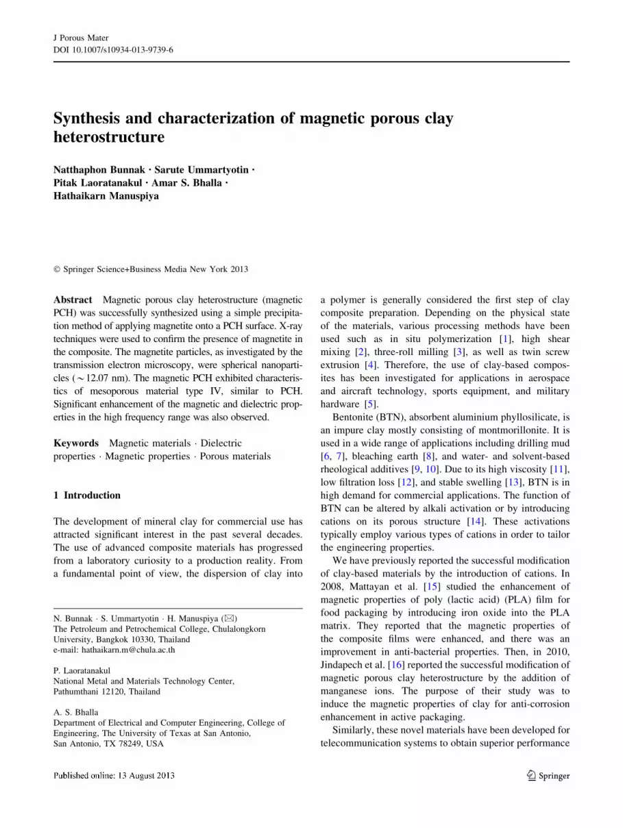
powder was magnetic. Figure 1 displays typical FTIR
spectra of the materials. It was found that the spectrum of
magnetic PCH is similar to the spectrum of PCH, indi-
cating Si–O–Si bending vibrations (476 and 475 cm-1),
Si–O–Si symmetric stretching (785 and 796 cm-1), Si–
O–Si asymmetric stretching (1,085 and 1,097 cm-1), H–
O–H bending vibrations of physically adsorbed water
(1,618 and 1,640 cm-1), and O–H stretching vibrations of
hydrogen-bonded surface silanol groups and physically
adsorbed water (3,398 and 3,440 cm-1) [25]. The FTIR
spectra are in good agreement with previously reported
results [15–17, 25]. There was no observed peak indi-
cating the presence of free iron oxide after synthesis;
consequently, x-ray techniques were used to confirm the
presence of magnetite.
Table 1 Chemical composition of PCH and magnetic PCH
Sample Concentration (%)
Mg Al Si K Ca Fe Cu Cl Ti
PCH 0.72 4.91 92.55 0.18 1.04 0.30 0.05 0.06 0.10
Magnetic PCH 0.52 4.71 66.45 0.08 0.47 26.23 0.23 1.24 0.07
J Porous Mater
123
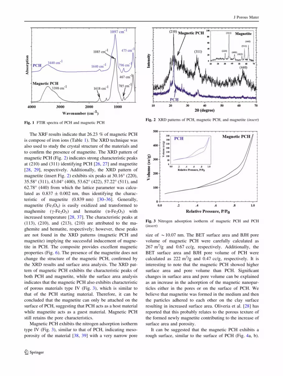
The XRF results indicate that 26.23 % of magnetic PCH
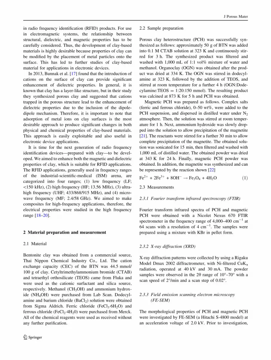
is compose of iron ions (Table 1). The XRD technique was
also used to study the crystal structure of the materials and
to confirm the presence of magnetite. The XRD pattern of
magnetic PCH (Fig. 2) indicates strong characteristic peaks
at (210) and (311) identifying PCH [26, 27] and magnetite
[28, 29], respectively. Additionally, the XRD pattern of
magnetite (insert Fig. 2) exhibits six peaks at 30.16� (220),
35.58� (311), 43.04� (400), 53.62� (422), 57.22� (511), and
62.78� (440) from which the lattice parameter was calcu-
lated as 0.837 ± 0.002 nm, thus identifying the charac-
teristic of magnetite (0.839 nm) [30–36]. Generally,
magnetite (Fe3O4) is easily oxidized and transformed to
maghemite (c-Fe2O3) and hematite (a-Fe2O3) with
increased temperature [28, 37]. The characteristic peaks at
(113), (210), and (213), (210) are attributed to the ma-
ghemite and hematite, respectively; however, these peaks
are not found in the XRD patterns (magnetic PCH and
magnetite) implying the successful inducement of magne-
tite in PCH. The composite provides excellent magnetic
properties (Fig. 6). The presence of the magnetite does not
change the structure of the magnetic PCH, confirmed by
the XRD results and surface area analysis. The XRD pat-
tern of magnetic PCH exhibits the characteristic peaks of
both PCH and magnetite, while the surface area analysis
indicates that the magnetic PCH also exhibits characteristic
of porous materials type IV (Fig. 3), which is similar to
that of the PCH starting material. Therefore, it can be
concluded that the magnetite can only be attached on the
surface of PCH, suggesting that PCH acts as a host material
while magnetite acts as a guest material. Magnetic PCH
still retains the pore characteristics.
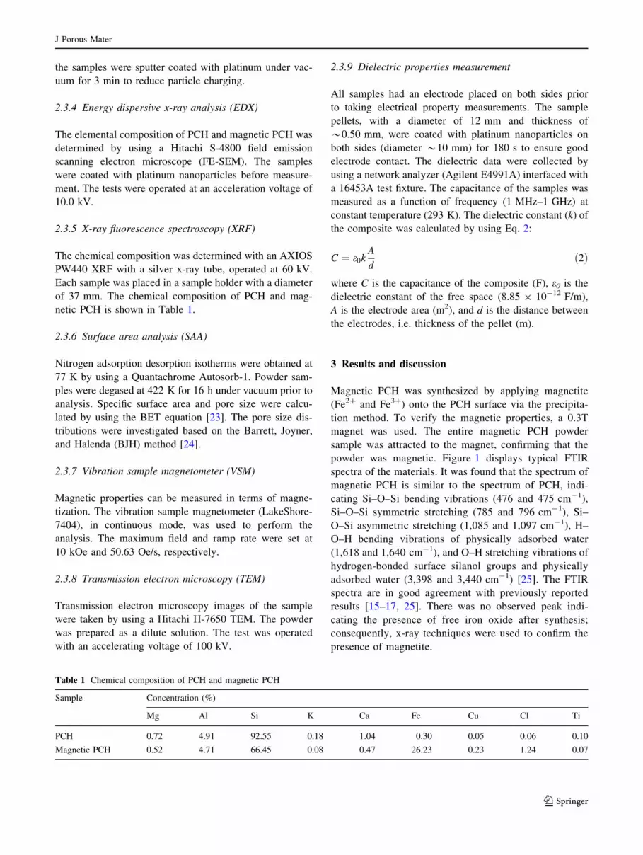
Magnetic PCH exhibits the nitrogen adsorption isotherm
type IV (Fig. 3), similar to that of PCH, indicating meso-
porosity of the material [38, 39] with a very narrow pore
size of *10.07 nm. The BET surface area and BJH pore
volume of magnetic PCH were carefully calculated as
267 m2/g and 0.67 cc/g, respectively. Additionally, the
BET surface area and BJH pore volume of PCH were
calculated as 222 m2/g and 0.47 cc/g, respectively. It is
interesting to note that the magnetic PCH showed higher
surface area and pore volume than PCH. Significant
changes in surface area and pore volume can be explained
as an increase in the adsorption of the magnetic nanopar-
ticles either in the pores or on the surface of PCH. We
believe that magnetite was formed in the medium and then
the particles adhered to each other on the clay surface
resulting in increased surface area. Oliveria et al. [28] has
reported that this probably relates to the porous texture of
the formed newly magnetite contributing to the increase of
surface area and porosity.
It can be suggested that the magnetic PCH exhibits a
rough surface, similar to the surface of PCH (Fig. 4a, b).
Fig. 1 FTIR spectra of PCH and magnetic PCHFig. 2 XRD patterns of PCH, magnetic PCH, and magnetite (insert)
Fig. 3 Nitrogen adsorption isotherm of magnetic PCH and PCH
(insert)
J Porous Mater
123
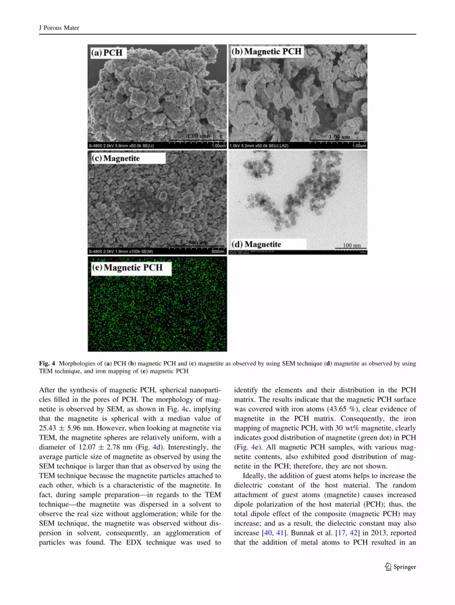
After the synthesis of magnetic PCH, spherical nanoparti-
cles filled in the pores of PCH. The morphology of mag-
netite is observed by SEM, as shown in Fig. 4c, implying
that the magnetite is spherical with a median value of
25.43 ± 5.96 nm. However, when looking at magnetite via
TEM, the magnetite spheres are relatively uniform, with a
diameter of 12.07 ± 2.78 nm (Fig. 4d). Interestingly, the
average particle size of magnetite as observed by using the
SEM technique is larger than that as observed by using the
TEM technique because the magnetite particles attached to
each other, which is a characteristic of the magnetite. In
fact, during sample preparation—in regards to the TEM
technique—the magnetite was dispersed in a solvent to
observe the real size without agglomeration; while for the
SEM technique, the magnetite was observed without dis-
persion in solvent, consequently, an agglomeration of
particles was found. The EDX technique was used to
identify the elements and their distribution in the PCH
matrix. The results indicate that the magnetic PCH surface
was covered with iron atoms (43.65 %), clear evidence of
magnetite in the PCH matrix. Consequently, the iron
mapping of magnetic PCH, with 30 wt% magnetite, clearly
indicates good distribution of magnetite (green dot) in PCH
(Fig. 4e). All magnetic PCH samples, with various mag-
netite contents, also exhibited good distribution of mag-
netite in the PCH; therefore, they are not shown.
Ideally, the addition of guest atoms helps to increase the
dielectric constant of the host material. The random
attachment of guest atoms (magnetite) causes increased
dipole polarization of the host material (PCH); thus, the
total dipole effect of the composite (magnetic PCH) may
increase; and as a result, the dielectric constant may also
increase [40, 41]. Bunnak et al. [17, 42] in 2013, reported
that the addition of metal atoms to PCH resulted in an
Fig. 4 Morphologies of (a) PCH (b) magnetic PCH and (c) magnetite as observed by using SEM technique (d) magnetite as observed by using
TEM technique, and iron mapping of (e) magnetic PCH
J Porous Mater
123
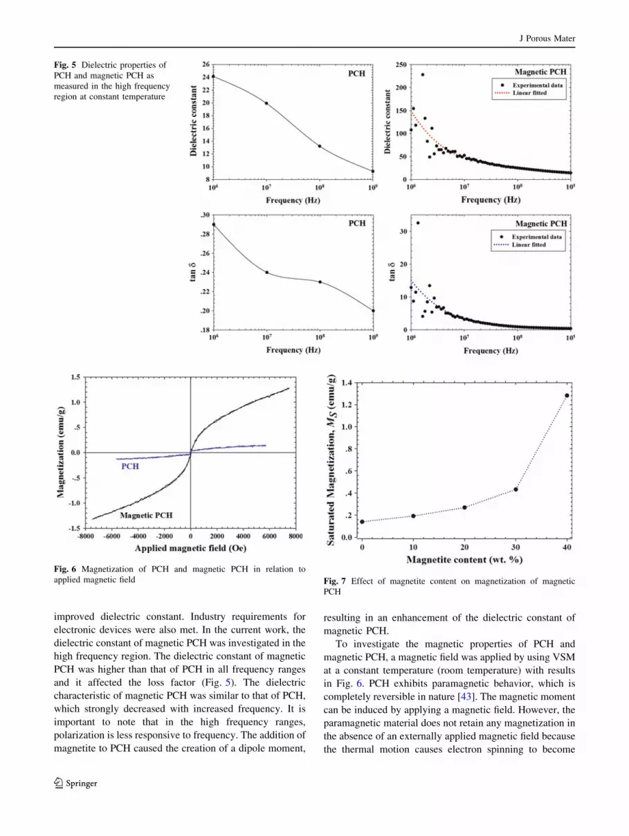
improved dielectric constant. Industry requirements for
electronic devices were also met. In the current work, the
dielectric constant of magnetic PCH was investigated in the
high frequency region. The dielectric constant of magnetic
PCH was higher than that of PCH in all frequency ranges
and it affected the loss factor (Fig. 5). The dielectric
characteristic of magnetic PCH was similar to that of PCH,
which strongly decreased with increased frequency. It is
important to note that in the high frequency ranges,
polarization is less responsive to frequency. The addition of
magnetite to PCH caused the creation of a dipole moment,
resulting in an enhancement of the dielectric constant of
magnetic PCH.
To investigate the magnetic properties of PCH and
magnetic PCH, a magnetic field was applied by using VSM
at a constant temperature (room temperature) with results
in Fig. 6. PCH exhibits paramagnetic behavior, which is
completely reversible in nature [43]. The magnetic moment
can be induced by applying a magnetic field. However, the
paramagnetic material does not retain any magnetization in
the absence of an externally applied magnetic field because
the thermal motion causes electron spinning to become
Fig. 5 Dielectric properties of
PCH and magnetic PCH as
measured in the high frequency
region at constant temperature
Fig. 6 Magnetization of PCH and magnetic PCH in relation to
applied magnetic field Fig. 7 Effect of magnetite content on magnetization of magnetic
PCH
J Porous Mater
123
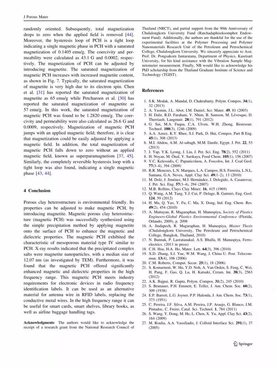
randomly oriented. Subsequently, total magnetization
drops to zero when the applied field is removed [44].
Moreover, the hysteresis loop of PCH is a tight loop
indicating a single magnetic phase in PCH with a saturated
magnetization of 0.1405 emu/g. The coercivity and per-
meability were calculated as 43.1 G and 0.0002, respec-
tively. The magnetization of PCH can be adjusted by
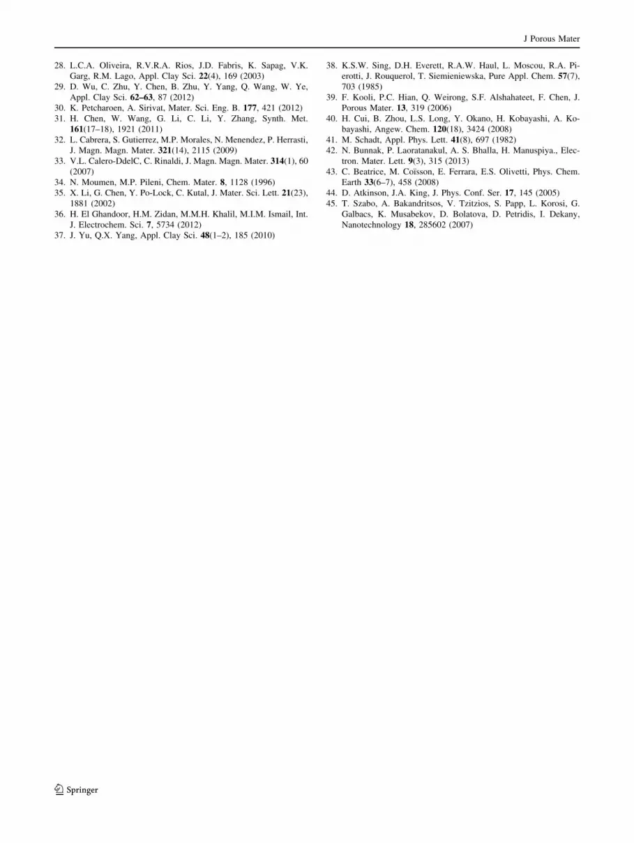
introducing magnetite. The saturated magnetization of
magnetic PCH increases with increased magnetite content,
as shown in Fig. 7. Typically, the saturated magnetization
of magnetite is very high due to its electron spin. Chen
et al. [31] has reported the saturated magnetization of
magnetite as 65 emu/g while Petcharoen et al. [30] has
reported the saturated magnetization of magnetite as
57 emu/g. In this work, the saturated magnetization of
magnetic PCH was found to be 1.2820 emu/g. The coer-
civity and permeability were also calculated as 26.6 G and
0.0009, respectively. Magnetization of magnetic PCH
jumps with an applied magnetic field; therefore, it is clear
that magnetization could be easily adjusted by applying a
magnetic field. In addition, the total magnetization of
magnetic PCH falls down to zero without an applied
magnetic field, known as superparamagnetism [37, 45].
Similarly, the completely reversible hysteresis loop with a
tight loop was also found, indicating a single magnetic
phase [43, 44].
4 Conclusion
Porous clay heterostructure is environmental friendly. Its
properties can be adjusted to make magnetic PCH, by
introducing magnetite. Magnetic porous clay heterostruc-
ture (magnetic PCH) was successfully synthesized using
the simple precipitation method by applying magnetite
onto the surface of PCH to enhance the magnetic and
dielectric properties. The magnetic PCH exhibited the
characteristic of mesoporous material type IV similar to
PCH. X-ray results indicated that the precipitated complex
salts were magnetite nanoparticles, with a median size of
12.07 nm (as investigated by TEM). Furthermore, it was
found that the magnetic PCH offered significantly
enhanced magnetic and dielectric properties in the high
frequency range. This magnetic PCH meets industry
requirements for electronic devices in radio frequency
identification labels. It can be used as an alternative
material for antenna wire in RFID labels, replacing the
conductive metal wires. In the high frequency range it can
be useful for smart cards, smart shelves, library books, as
well as airline baggage handling tags.
Acknowledgments The authors would like to acknowledge the
receipt of a research grant from the National Research Council of
Thailand (NRCT), and partial support from the 90th Anniversary of
Chulalongkorn University Fund (Ratchadaphiseksomphot Endow-
ment Fund). Additionally, the authors are thankful for the use of the
experimental facilities at the Polymer Processing and Polymer
Nanomaterials Research Unit of the Petroleum and Petrochemical
College, Chulalongkorn University. We sincerely appreciate to Asst.
Prof. Dr. Pongsakorn Jantaratana, Department of Physics, Kasetsart
University, for his kind assistance with the Vibration Sample Mag-
netometer measurement. Finally, NB would like to acknowledge his
PhD scholarship from the Thailand Graduate Institute of Science and
Technology (TGIST).
References
1. S.K. Modak, A. Mandal, D. Chakrabarty, Polym. Compos. 34(1),
32 (2013)
2. A. Yasmin, J.L. Abot, I.M. Daniel, Scr. Mater. 49, 81 (2003)
3. H. Dalir, R.D. Farahani, V. Nhim, B. Samson, M. Levesque, D.
Therriault, Langmuir. 28(1), 791 (2012)
4. G. Sui, M.A. Fuqua, C.A. Ulven, W.H. Zhong, Bioresour.
Technol. 100(3), 1246 (2009)
5. A.A. Azeez, K.Y. Rhee, S.J. Park, D. Hui, Compos. Part B Eng.
45(1), 308 (2013)
6. M.I. Abdou, A.M. Al-sabagh, M.M. Dardir, Egypt. J. Pet. 22, 53
(2013)
7. J. Yap, Y.K. Leong, J. Liu, J. Pet. Sci. Eng. 78(2), 552 (2011)
8. H. Noyan, M. Onal, Y. Sarıkaya, Food Chem. 105(1), 156 (2007)
9. V.C. Kelessidis, C. Papanicolaou, A. Foscolos, Int. J. Coal Geol.
77(3–4), 394 (2009)
10. R.R. Menezes, L.N. Marques, L.A. Campos, H.S. Ferreira, L.N.L.
Santana, G.A. Neves, Appl. Clay Sci. 49(1–2), 13 (2010)
11. M. Dolz, J. Jimenez, M.J. Hernandez, J. Delegido, A. Casanovas,
J. Pet. Sci. Eng. 57(3–4), 294 (2007)
12. M.B. Rollins, Clays Clay Miner. 16, 415 (1969)
13. Q. Wang, A.M. Tang, Y.J. Cui, P. Delage, B. Gatmiri, Eng. Geol.
124, 59 (2012)
14. H. Ma, Q. Yao, Y. Fu, C. Ma, X. Dong, Ind. Eng. Chem. Res.
49(2), 454 (2010)
15. A. Mattayan, R. Magaraphan, H. Manuspiya, Society of Plastics
Engineers-Global Plastics Environmental Conference (Florida,
Orlando, 2009), p. 2098
16. A. Jindapech, R. Magaraphan, H. Manuspiya, Master Thesis
(Chulalongkorn University, The Petroleum and Petrochemical
College, Bangkok, Thailand, 2010)
17. N. Bunnak, P. Laoratanakul, A.S. Bhalla, H. Manuspiya, Ferro-
electrics. (2013 in press)
18. C.H. Hsu, H.A. Ho, Mater. Lett. 64(3), 396 (2010)
19. X.D. Zhang, S.J. Yue, W.M. Wang, J. China U. Post. Telecom-
mun. 13(4), 106 (2006)
20. C.M. Roberts, Comput. Secur. 25(1), 18 (2006)
21. S. Komarneni, W. Hu, Y.D. Noh, A. Van Orden, S. Feng, C. Wei,
H. Pang, F. Gao, Q. Lu, H. Katsuki, Ceram. Int. 38(3), 2563
(2012)
22. A.K. Bajpai, R. Gupta, Polym. Compos. 31(2), 245 (2010)
23. S. Brunauer, P.H. Emmett, E. Teller, J. Am. Chem. Soc. 60(2),
309 (1938)
24. E.P. Barrett, L.G. Joyner, P.P. Halenda, J. Am. Chem. Soc. 73(1),
373 (1951)
25. C. Pereira, J.F. Silva, A.M. Pereira, J.P. Araujo, G. Blanco, J.M.
Pintadoc, C. Freire, Catal. Sci. Technol. 1, 784 (2011)
26. S. Wang, Y. Dong, M. He, L. Chen, X. Yu, Appl. Clay Sci. 43(2),
164 (2009)
27. M. Roulia, A.A. Vassiliadis, J. Colloid Interface Sci. 291(1), 37
(2005)
J Porous Mater
123
28. L.C.A. Oliveira, R.V.R.A. Rios, J.D. Fabris, K. Sapag, V.K.
Garg, R.M. Lago, Appl. Clay Sci. 22(4), 169 (2003)
29. D. Wu, C. Zhu, Y. Chen, B. Zhu, Y. Yang, Q. Wang, W. Ye,
Appl. Clay Sci. 62–63, 87 (2012)
30. K. Petcharoen, A. Sirivat, Mater. Sci. Eng. B. 177, 421 (2012)
31. H. Chen, W. Wang, G. Li, C. Li, Y. Zhang, Synth. Met.
161(17–18), 1921 (2011)
32. L. Cabrera, S. Gutierrez, M.P. Morales, N. Menendez, P. Herrasti,
J. Magn. Magn. Mater. 321(14), 2115 (2009)
33. V.L. Calero-DdelC, C. Rinaldi, J. Magn. Magn. Mater. 314(1), 60
(2007)
34. N. Moumen, M.P. Pileni, Chem. Mater. 8, 1128 (1996)
35. X. Li, G. Chen, Y. Po-Lock, C. Kutal, J. Mater. Sci. Lett. 21(23),
1881 (2002)
36. H. El Ghandoor, H.M. Zidan, M.M.H. Khalil, M.I.M. Ismail, Int.
J. Electrochem. Sci. 7, 5734 (2012)
37. J. Yu, Q.X. Yang, Appl. Clay Sci. 48(1–2), 185 (2010)
38. K.S.W. Sing, D.H. Everett, R.A.W. Haul, L. Moscou, R.A. Pi-
erotti, J. Rouquerol, T. Siemieniewska, Pure Appl. Chem. 57(7),
703 (1985)
39. F. Kooli, P.C. Hian, Q. Weirong, S.F. Alshahateet, F. Chen, J.
Porous Mater. 13, 319 (2006)
40. H. Cui, B. Zhou, L.S. Long, Y. Okano, H. Kobayashi, A. Ko-
bayashi, Angew. Chem. 120(18), 3424 (2008)
41. M. Schadt, Appl. Phys. Lett. 41(8), 697 (1982)
42. N. Bunnak, P. Laoratanakul, A. S. Bhalla, H. Manuspiya., Elec-
tron. Mater. Lett. 9(3), 315 (2013)
43. C. Beatrice, M. Coısson, E. Ferrara, E.S. Olivetti, Phys. Chem.
Earth 33(6–7), 458 (2008)
44. D. Atkinson, J.A. King, J. Phys. Conf. Ser. 17, 145 (2005)
45. T. Szabo, A. Bakandritsos, V. Tzitzios, S. Papp, L. Korosi, G.
Galbacs, K. Musabekov, D. Bolatova, D. Petridis, I. Dekany,
Nanotechnology 18, 285602 (2007)
J Porous Mater
123