photoconductivity and gas sensing properties of zno
TRANSCRIPT

Photoconductivity and gas sensing propertiesof ZnO nanowire devices
Dissertation
zur Erlangung des akademischen Grades
doctor rerum naturalium (Dr. rer. nat)
vorgelegt dem Rat der Physikalisch-Astronomischen Fakultat
der Friedrich-Schiller-Universitat Jena
von Dottore Magistrale in Fisica Davide Cammi
geboren am 24.04.1985 in Fiorenzuola d’Arda (PC), Italien

Gutachter:
1. Prof. Dr. Carsten Ronning, FSU Jena
2. Prof. Dr. Tobias Voss, TU Braunschweig
3. Prof. Dr. Giancarlo Cicero, Politecnico di Torino (Turin, Italien)
Tag der Disputation: 23.02.2016

Contents
Contents 1
1 Introduction 3
1.1 Motivation . . . . . . . . . . . . . . . . . . . . . . . . . . . . . . . . . . . 3
1.2 Outline of the thesis . . . . . . . . . . . . . . . . . . . . . . . . . . . . . 5
2 Background and state of the art 7
2.1 Zinc oxide . . . . . . . . . . . . . . . . . . . . . . . . . . . . . . . . . . . 7
2.1.1 Properties and applications . . . . . . . . . . . . . . . . . . . . . 7
2.1.2 Growth . . . . . . . . . . . . . . . . . . . . . . . . . . . . . . . . 9
2.1.3 Properties of nanowires . . . . . . . . . . . . . . . . . . . . . . . . 10
2.1.4 Doping of semiconductor nanowires . . . . . . . . . . . . . . . . . 12
2.2 Surface properties of semiconductors . . . . . . . . . . . . . . . . . . . . 14
2.2.1 Pinning of the Fermi level . . . . . . . . . . . . . . . . . . . . . . 14
2.2.2 Surface band bending in ZnO nanowires . . . . . . . . . . . . . . 15
2.3 Metal - Semiconductor interface . . . . . . . . . . . . . . . . . . . . . . . 16
2.4 Nanowire field-effect transistors . . . . . . . . . . . . . . . . . . . . . . . 18
2.5 Persistence of the photoconductivity . . . . . . . . . . . . . . . . . . . . 20
2.6 Chemical sensing with ZnO . . . . . . . . . . . . . . . . . . . . . . . . . 23
3 Experimental 26
3.1 Nanowire growth . . . . . . . . . . . . . . . . . . . . . . . . . . . . . . . 26
3.2 Photolithography . . . . . . . . . . . . . . . . . . . . . . . . . . . . . . . 26
3.3 Electrical characterization . . . . . . . . . . . . . . . . . . . . . . . . . . 28
3.3.1 Setup . . . . . . . . . . . . . . . . . . . . . . . . . . . . . . . . . 28
3.3.2 Photoconductivity measurements . . . . . . . . . . . . . . . . . . 29
3.3.3 Sensing measurements . . . . . . . . . . . . . . . . . . . . . . . . 30
3.4 Photoluminescence . . . . . . . . . . . . . . . . . . . . . . . . . . . . . . 31
3.5 Ion beam implantation . . . . . . . . . . . . . . . . . . . . . . . . . . . . 32
4 Sub-bandgap photoconductivity in ZnO nanowires 33
4.1 Motivation . . . . . . . . . . . . . . . . . . . . . . . . . . . . . . . . . . . 33
4.2 Electrical properties of ZnO NW FETs in dark . . . . . . . . . . . . . . . 34
4.2.1 Contact properties . . . . . . . . . . . . . . . . . . . . . . . . . . 34
1

2
4.2.2 Transfer characteristics . . . . . . . . . . . . . . . . . . . . . . . . 37
4.3 Gate voltage modulation of photoresponse . . . . . . . . . . . . . . . . . 40
4.4 Conclusions . . . . . . . . . . . . . . . . . . . . . . . . . . . . . . . . . . 45
5 Persistent photoconductivity in ZnO nanowires 47
5.1 Atmosphere dependence of the persistent photoconductivity . . . . . . . 47
5.2 Dynamics of the photoconductivity decay . . . . . . . . . . . . . . . . . . 53
5.3 Conclusions . . . . . . . . . . . . . . . . . . . . . . . . . . . . . . . . . . 65
6 Activation of Al dopants in ZnO nanowires 66
6.1 Introduction . . . . . . . . . . . . . . . . . . . . . . . . . . . . . . . . . . 66
6.2 Implantation procedure . . . . . . . . . . . . . . . . . . . . . . . . . . . . 68
6.3 Thermal stability of implanted ZnO nanowire devices . . . . . . . . . . . 68
6.4 Optical properties of implanted ZnO nanowires . . . . . . . . . . . . . . 71
6.5 Photoconductivity properties of implanted ZnO nanowires . . . . . . . . 74
6.5.1 Photoresponse . . . . . . . . . . . . . . . . . . . . . . . . . . . . . 74
6.5.2 Persistent photoconductivity in Al doped ZnO nanowires . . . . . 76
6.6 Conclusions . . . . . . . . . . . . . . . . . . . . . . . . . . . . . . . . . . 80
7 Hydrogen sensing with ZnO nanowires 82
7.1 Motivation . . . . . . . . . . . . . . . . . . . . . . . . . . . . . . . . . . . 82
7.2 Hydrogen sensing properties of untreated ZnO nanowire devices . . . . . 84
7.3 Argon and oxygen plasma treatments . . . . . . . . . . . . . . . . . . . . 87
7.4 Annealing in oxygen atmosphere . . . . . . . . . . . . . . . . . . . . . . . 92
7.5 Conclusions . . . . . . . . . . . . . . . . . . . . . . . . . . . . . . . . . . 95
8 Summary and outlook 96
Bibliography 100
Appendix 130

Chapter 1
Introduction
1.1 Motivation
The field of nanotechnology has received in the last two decades an increasingly impor-
tance in all research areas of natural sciences [1–4]. The term refers to a large variety
of techniques and applications concerning objects, which typically have at least one di-
mension not larger than few hundreds of nanometers. Well known examples of such
nanostructures are quantum wells, quantum dots, nanowires and nanotubes [5].
From the perspective of the basic research, the possibility of dealing with objects of
reduced dimensionality offers the opportunity to investigate physical processes at the
nanoscale level. Under these conditions several physical properties start to deviate from
those, which are typically observed in bulk materials. For instance, Band gap, density of
states as well as electric, optical and mechanical properties can be strongly modulated
by the size of the nanostructures, due to the quantum confinement of charge carriers
[6–11]. Compared to bulk structures, nanostructures are also characterized by a signifi-
cantly larger surface to volume ratio, which leads to a dramatic impact of the surface on
fundamental physical processes such as charge transport and interaction between matter
and light [12].
Furthermore, the deep comprehension of the nature laws at the nanoscale level opens up
tremendous possibilities in terms of applications. The potentialities of nanostructures,
which are mainly based on their high surface to volume ratio, are nowadays intensively
exploited in electronics, photonics and bio-sciences [13]. These include in particular their
extreme sensitivity to surface related processes, such as molecular detection and catalytic
3

Chapter 1. Introduction 4
activity [14, 15], enhanced interaction with electromagnetic radiation [12] and the possi-
bility to control their electrical, magnetic and properties through the quantum confine-
ment of charge carriers [16]. Furthermore, the process of device miniaturization allows
cosiderable reduction of the power consumption, enhanced operation speed, as well as
improved data processing and transmission [17]. Among nanostructures, semiconductor
nanowires (NWs) are the most promising building components for nano-electronics and
nano-photonics devices [18, 19]. They typically show an approximatively cylindrical ge-
ometry, with diameter around 100 nm and length up to tens of micrometers [5, 20]. Due
to these unique geometrical properties, they can be easily integrated into electronics de-
vices as active semiconducting channel [21, 22] or can act as photonics waveguides and
resonant cavities for nanowire based lasers [19, 23, 24]. Moreover, nanowire morphology
offers optimal features for energy harvesting [25, 26], gas and bio-sensing applications
[27, 28], allowing high conversion efficiency and low detection limit.
Semiconductor nanowires are available in a large variety of material compositions, such
as silicon, III-V and II-VI compounds. Among them, metal oxide nanowires represent
a large class of versatile nanostructures, which have been widely investigated as active
component in opto-electronic devices, field-effect transistors and gas sensors [29, 30]. In
particular, ZnO has attracted increasingly interest due to the combinations of unique
properties. These include for instance the large exciton energy of 60 meV, which en-
sures intense excitonic emission at room temperature, the intrinsic n-type conductivity,
as well as the high resistence to harsh environment and the biocompatibility [31]. Fur-
thermore, ZnO nanowires can be easily grown via vapor transport technique enabled
by vapor-liquid-solid method (VLS), unlike nanowires based on many other compound
semiconductors, which are typically synthetized through more complex chemical vapor
deposition procedures [20]. Recent studies reported about extremely high photo-gain in
ZnO nanowires assembled as UV photodetectors [32], as well as promising performances
in chemical and bio sensing [33–36].
However, the large-scale applicability of ZnO nanowire devices is currently hindered by
the limited control over their electrical properties. In particular, the strong influence of
the surrounding environment on the device conductivity may be deleterious for photode-
tection applications, in which the measurement reproducibility should not be affected by
the surrounding environment. Furthermore, the long persistence of the photoconductivity
(PPC) after light excitation, whose origin is still under debate [37–39], affects deleterio-
suly the recovery speed of ZnO nanowire based photodetectors. The development of an
adequate model, which can precisely describe this effect, would be highly beneficial for

Chapter 1. Introduction 5
an effective controll over the PPC. An additional issue concerns the eventual presence
of localized defect levels in the band gap of the nanowire, which may drastically alter
the charge transport and the photoconductivity properties of the entire device. Defect
states are typically located at interfaces, such as the surface or contact regions, and they
can easily form during the processing steps, which are required to produce the nanowire
devices. Additionally, the specific modification of the device properties requires the op-
timization of various treatment procedures, whose impact on ZnO nanowire devices is
still largely unexplored. This is for instance the case of ion beam implantation or plasma
treatments on contacted ZnO nanowires or treatments in plasma atmospheres.
Furthermore, despite the large number of publications about chemical and bio sensing
with ZnO nanowires, the specific detection mechanism is still unclear and the gas sensi-
tivity at room temperature, as well as the gas selectivity (i.e. the ability to distinguish
different molecular species), are quite poor. These facts reflect more in general that the
impact of the surface on the charge transport properties of ZnO nanowires is not fully
understood and reveal the need of further studies and investigations.
The beneficials from a deeper knowledge about the mentioned issues include in particular
the possibility to selectively modify ZnO nanowire devices according to the specific wish
and to enlarge their functionalities in view of improved applications.
1.2 Outline of the thesis
In this thesis, the photoconductivity and gas sensing properties of ZnO nanowires assem-
bled into electronic devices are investigated.
The properties of ZnO as a material system in general and in the nanowire morphology in
particular are introduced in chapter 2, along with the doping of semiconductor nanowires
as well as the theory about the metal-semiconductor junction and the nanowire based
field-effect transistor (FET). In the same chapter, the state of the art about the persistent
photoconductivity and the gas sensing with ZnO is also presented. The experimental
methods are described in chapter 3. These include the growth of the nanowires and the
device preparation, as well as the subsequent procedures for the modification of the device
properties and the exploited characterization techniques.
Chapter 4 is dedicated to the influence of defect levels on the sub-bandgap photocon-
ductivtiy in ZnO nanowire field-effect transistors. In this configuration the population
of defect levels, and therefore the device photoresponse below the band gap of ZnO, can
be controlled by means of the gate voltage. The contribution of interfacial levels to the

Chapter 1. Introduction 6
photoconductivity is investigated through a combined electrical and photoluminescence
characterization.
Chapter 5 concerns the influence of the surrounding atmosphere on the above band gap
photoconductivity properties of contacted ZnO nanowires. The photoresponse and the
photoconductivity decay after UV excitation have been investigated in particular in vac-
uum, inert atmosphere and air. The dependence of the photoconduction process on the
surrounding environment is discussed in terms of modulation of the surface band bend-
ing. A quantitative analysis of the persistent photoconductivity by means of the so-called
Elovich equation for adsorption processes is then proposed.
Chapter 6 deals with the aluminum doping of contacted ZnO nanowires by means of
ion beam implantation. At first, the optimal conditions for the post-implantation ther-
mal activation of the aluminum ions as shallow donors are discussed. The impact of
the implantation process on the optical and electrical properties of the devices is then
investigated, giving particular emphasis on the change induced in the photoconduction
process. The investigation is enriched and completed through the comparison with argon
implanted devices.
Finally, in chapter 7 the hydrogen sensing properties of ZnO nanowire devices at room
temperature are investigated. The response of the devices toward hydrogen molecules
was measured under different gas concentration and a model for the sensing mechanism
is proposed. Plasma treatments in argon and oxygen atmospheres as well as thermal
annealing in oxygen are then explored as possible methods to enhance the gas sensitivity
of the devices.
Detailed motivations of the performed experiments are presented at the beginning of the
respective chapters, which are concluded with a summary of the most significant results.
A conclusive summary of the thesis work and a corresponding outlook are given in chapter
8.

Chapter 2
Background and state of the art
2.1 Zinc oxide
2.1.1 Properties and applications
Zinc oxide (ZnO) is a one of the most important II-VI compound semiconductors and
has been investigated since the first quarter of the last century [40]. The continuously
growing interest arises from the possibility to grow high quality ZnO single crystals and
nanostructures at relatively low production costs [41–45].
ZnO is a wide band gap semiconductor with a direct band gap of Eg ∼ 3.37 eV at room
temperature [46]. It crystallizes in the hexagonal wurzite structure, with every oxygen
atom tetraedrically bound to four zinc atoms (Figure 2.1). This structure lacks an in-
version plane perpendicular to the c-axis. Therefore, surfaces perpendicular to the c-axis
show either Zn-polarity or O-polarity. Furthermore, the low symmetry of the wurzite
crystal structure combined with the large electromechanical coupling gives rise to strong
piezoelectric and pyroelectric properties [31]. Although the tetrahedral coordination re-
veals a partial covalent nature of the chemical bond, the high electronegativity difference
between oxygen and zinc confers the crystal a strong ionic character [47]. As a conse-
quence, the valence band is mainly determined by the overlap of completely filled 2p
orbitals of O2−, while the condution band is formed by empty orbitals of Zn2+.
Despite the wide band gap, ZnO is typically characterized by spontaneous n-type conduc-
tivity at room temperature. According to density-functional-theory (DFT) calculations
[48–51] and experimental evidences [52–54], hydrogen atoms incorporated during growth,
either at interstitial (Hi) or substitutional positions (HO), are considered the main donor
7

2 Background and state of the art 8
Figure 2.1: Schematic rapresentation of the wurzite unit cell of ZnO, with everyoxygen atom (in yellow) tetraedrically bound to four zinc atoms (in red). Adapted from
[63].
impurites in ZnO. The contribution from intrinsic defects to the spontaneous n-type con-
ductivity is essentially negligible. Interstitial zinc atoms (Zni) or zinc antisites (ZnO) are
shallow donors, but they are present in ZnO only at low concentrations due to the high
formation energy under n-type conditions [31]. Oxygen vacancies (VO) give instead origin
to deep donor levels [55, 56] and thus cannot provide electrons to the conduction band.
Reported values for the donor concentration in nominally undoped ZnO bulk crystals
and thin film range from 1016 cm−3 to 1019 cm−3 at room temperature, largely depending
on the adopted growth technique [57–61]. The corresponding electron mobility, typically
determined by means of Hall measurements, critically depends on the crystal quality. As
such, it is strongly influenced by the growth tecnique, and in case of thin film structures
also by the chosen growth substrate, whose eventual lattice mismatch with ZnO can in-
duce strain and formation of grain boundaries [31]. The highest reported values of the
electron mobility in ZnO bulk and thin film structures at room temperature are 205 [41]
and 440 cm2·V −1s−1 [62], respectively.
The research and application areas of ZnO are particularly wide and includes several fields
of technology, such as photonics, electronics, spintronics, energy harvesting and sensing
[45, 64]. Due to the wide band gap and the high excitonic binding energy of 60 meV,
ZnO has been considered attractive for the development of opto-electronic devices and
light emitting diodes in the near UV range, emerging as possible alternative material to
GaN [65, 66]. The possibility to introduce a large amount of n-type dopants (see also

2 Background and state of the art 9
Section 2.1.4), combined with the high transparency in the infra-red and visible ranges
of the spectrum, is particularly desirable in electronics for the production of transparent
thin-film transistors [67–69] and in photovoltaics for the development of new transparent
electrical contacts [70, 71]. On the other hand, band-gap engineering of ZnO over a
broad energy range by alloying with Mg and Cd have been successfully demonstrated
[72]. Doping of ZnO with magnetic impurities, like manganese, cobalt, or nickel, can
be exploited for the production of spintronic devices, in which the electron spin is used
for writing and reading informations [73]. The strong piezoelectricity allows the use of
ZnO for piezoelectric energy harvesting and conversion, particularly for the production
of electromechanically coupled sensors and actuators [25]. Furthermore, due to the high
chemical stability, biocompatibility and the sensitivity of the surface to the environment
conditions, ZnO have been successfully considered for gas and bio sensing application
[30].
2.1.2 Growth
Growth of ZnO structures can be carried out by a large variety of methods. Bulk crys-
tals are typically grown by hydrothermal techniques [42], vapor-phase transport [41] and
and pressurized melt growth [74]. The growth of ZnO thin films can be accomplished
by means of chemical vapor deposition (CVD) [59, 60], molecular-beam epitaxy (MBE)
[57, 58], laser ablation [75] and sputtering [76]. High crystal quality ZnO films can be
grown homoepitaxial on the native bulk crystal [57, 60], or on substrates with relatively
small lattice mismatch, such as Al2O3 [77, 78]. Alternative substrates with higher lattice
mismatch are for instance Si [79], SiC [78] and GaAs [80].
ZnO nanowires are often grown via the so-called metal catalyst assisted Vapor-Liquid-
Solid mechanism (VLS), firstly described by Ellis and Wagner in 1964 concerning the
growth of silicon whiskers [81]. In the VLS methods, a thin layer of a catalyst material
(typically gold) is deposited on a substrate and heated up above its melting temperature.
The source material is provided in vapor phase and gets incorporated into the liquid
catalyst droplet, forming an alloy. When the alloy becomes saturated, the source material
starts to segregate and in most of the cases re-crystallize at the interface between the
catalyst and the substrate. As the incorporation proceeds, the segregation continues in
vertical direction and the structure receives the typical shape of a nanowire, with diameter
comparable with the size of the catalyst droplet. Typical growth rate are in the order
of some several hundreds of nm/min up to few µm/min [82]. Beside the vertical growth
promoted by the VLS mechanism, also growth in the lateral direction at significantly

2 Background and state of the art 10
lower rate (nm/min) can be observed. This is caused by the direct deposition of the
source material on the side walls of the nanowire and is therefore called Vapor-Solid (VS)
growth. Since its activation requires typically high temperatures, the VLS mechanism
enables typically growth techiques which require high temperatures, such as physical and
chemical deposition, MBE and laser ablation. Additionally, also self-catalyzed growth
techniques [83] as well as solution growth methods at relatively low temperatures [84] can
be exploited fro the growth of ZnO nanowires, altough the crystal quality obtained in the
latter case may be quite poor.
2.1.3 Properties of nanowires
The reduction of the structure dimensionality to the nanometric scale leads to a dramatic
modifications of several properties of ZnO, which are strongly affected by the high sur-
face to volume ratio of nanostructures [32, 85, 86]. In general, the impact of the surface
on several properties of ZnO nanowires is revealed by their dependence on the nanowire
diameter, as well as on the atmosphere surrounding the nanowire. Furthermore, they can
be drastically modified by means of several surface treatments or surface functionaliza-
tion employing various material components (polymers, organic molecules, nanoparticles,
etc.).
The appearance of surface related effects in ZnO nanowires have been widely investigated
by several theoretical and experimental studies. Photoluminescence measurements re-
vealed for instance a strong dependence of the exciton related emission on the nanowire
diameter [85]. In particular, the intensity of the surface exciton emission tends to increase
as the diameter of the nanowire decreases. Moreover, a blue shift of the free exciton
emission has been theoretically predicted [87] and experimentally observed [88, 89] in
ultrathin nanowires with nanowire smaller than 10 nm. The effect has been attributed to
the widening of the band gap, which is induced by the quantum confinement of the charge
carriers in nanostructures with size comparable with the Bohr radius (≈ 2 nm in ZnO)
[90]. Enhancement of the surface exciton emission has been also observed by coating the
nanowire with organic and inorganic compounds [91], which induce passivation of surface
states. On the other hand, nanowires coated with metals exhibite reduced intensity of
the surface excitonic emission [92], due to the formation of metal-induced gap states in
the surface region [93], which leads to a higher electron trapping rate.
Size dependent transport properties in ZnO nanowires have been observed in dark condi-
tions as well as under light excitation [86, 94–96]. Electron mobility values at room tem-
perature for nanowires thinner than 200 nm range from 5 cm2·V −1s−1 to 75 cm2·V −1s−1,

2 Background and state of the art 11
which are much lower than that typically observed in bulk and thin film structures.
This effect has been attributed to the enhanced surface scattering and charge trapping
at surface defects, experienced by charge carriers as a result of the diameter shrinking.
Comparable results have been observed under photoexcitation conditions by means of
scanning photocurrent microscopy measurements, which revealed a significant decrease
of the minority carrier diffusion length for decreasing nanowire diameter [97]. However,
the electron mobility in ZnO nanowire based field effect transistors [95] is typically higher
than that measured in corresponding transistors based on thin films ( 0.01-10 cm2·V −1s−1)
[98, 99]. The electron mobility depends additionally on the environment sorrounding the
nanowire, being lower in oxygen rich atmopshere than in inert environments or at re-
duced pressure [100]. Such dependence can be suppressed by coating the surface with
a variety of molecular compounds [95, 96, 100–103]. Due to the passivation of surface
states, the electron mobility in coated nanowires can reach much higher values than in
bare nanowires, up to 1000 cm2·V −1s−1 [95].
The dependence of the electron mobility on the surrounding atmosphere reflects a more
general influence of the surrounding environment on the transport properties of ZnO
nanowires. Indeed, due to the high surface to volume ratio, the interaction of the surface
with gas and bio-molecules involves a large fraction of the nanowire body. Such effect can
be beneficially exploited in several applications, such as for instance chemical and bio-
sensing [14], allowing particularly high sensitivity for the detection of molecular species
in gas and in liquid phase [30, 104]. Significant examples are the successful detection of
the protein streptavidin down to a concentration of 2.5 nM [105] or the detection limit of
10 ppb in case of NO2 sensing, which is the lowest value achieved in gas sensing applica-
tions with nanowire based sensors [106]. Size dependent gas sensitivity has been reported
in case of oxygen [94] and hydrogen sensing [35] with ZnO nanowires, revealing in both
cases a three time enhancement of the response by shrinking the diameter from 200 to 100
nm. Further enhancement of the sensitivity can be achieved by surface functionalization
with noble metal nanoparticles or organic molecules. Noble metal nanoparticles promote
the catalytic dissociation of gas molecules into the atomic components, which interact
more strongly with the ZnO surface [34, 107]. Organic molecules are typically used for
the covalent binding with specific bio-molecules, which allows the development of highly
selective sensors for label free bio-sensing [36]. Furthermore, in contrast to traditional
polycristalline film gas sensors, which suffer from material instabilities due to grain coa-
lescence [108] and must be heated up to optimal operation temperatures (100 - 400 C)
by external heating elements [109], sensors based on ZnO nanowires ensure long-term

2 Background and state of the art 12
stability and considerable reduction in terms of power consumption (up to few tens of
µW) and device complexity. In particular, the former potentiality is guaranteed by the
higher crystal quality of the nanowires and the substantal absence of grain boundaries,
while the latter is based on the possibility to exploit self heating effects, favored by the
confinement of the structure and the weak thermal coupling of the nanowire with the
substrate and the electrodes, which leads to a reduction of the heat loss [110, 111].
The nanowire geometry leads also to a dramatic increase of the UV photoconductivity gain
up to 108 [32], which represents a five orders of magnitude enhancement in comparison
to ZnO thin film photodetectors [71]. Such extremely high gain has been attributed
to the enhanced separation efficiency of photogenerated charge carriers, promoted by
the reduced dimensionality of nanowires, and could in principle allow reaching single-
photon detectivity in homogeneous single nanowires [112, 113]. In particular, increase
of the UV photoconductivity gain have been observed in ZnO nanowires as a function
of the nanowire diameter shrinking [114]. Enhancement of the UV photoresponse, up
to three orders of magnitude [115, 116], has been also achieved by functionalizing the
nanowire surface with polymers and organic molecules [115, 117, 118] and noble metal
nanoparticles [119]. Furthermore, decoration of the nanowire surface with noble metal
nanoparticles [120] and semiconductor quantum dots [121, 122] can considerably enlarge
the photosensitivity of ZnO based photodetectors toward the visible and infrared spectral
ranges.
2.1.4 Doping of semiconductor nanowires
Doping of semiconductors is a fundamental process for the modification of the electric,
magnetic and optical properties of materials. The controlled introduction of desired im-
purities in semiconductor nanowires can be achieved via three different methods: doping
during growth or subsequent doping either by ion beam implantation or diffusion tech-
niques. Diffusion of dopants after growth offers the lowest controllability and requires typ-
ically suitable precursors and high temperature procedures. The latter issue is particularly
disadvantageous for nanowires, because their high surface/volume ratio leads to higher
thermal instability and eventual degradation at the required temperatures [123]. Doping
during growth has been successfully achieved in case of relatively large Si nanowires [124],
but inhomogeneous dopant distribution occurs in thinner nanowires and more generally
in nanowires based on other materials [125]. Additionally, morphological and structural
changes have been observed in compound semicondutor nanowires doped during growth
[126] and the solubility of several elements in the cristalline matrix is limited.

2 Background and state of the art 13
Ion beam implantation, which is based on the injection of ions of the desired impurities
at high energy, permits instead to overcome this limitations. In particular, it ensures
the availability of every element beyond the solubility limit and a precise control of the
dopant distribution, which can be tuned by specifically selecting the ion energy and
fluence [123]. The key issue of the implantation process consists in the loss of ion energy,
induced by their interaction with the electrons and the nuclei in the matter. The energy
loss, or stopping power, critically depends on the charge and the mass of ions, as well as
on the composition of the target material [123]. However, the main disadvantage of ion
implantation is the generation of defects in the crystal during the implantation process.
Therefore, post-implantation annealing treatments are typically required, in order to
recover the original crystal structure.
The modification of the electrical conductivity in ZnO via doping procedures ensures
higher potentialities for this material system in several application fields. Increase of the
n-type conductivity through the controlled introduction of shallow donor impurities leads
for instance to superior performances of ZnO as transparent conductive oxide and for
sensing applications. On the other hand, the possibility to introduce shallow acceptors
and to achieve consequently p-type doping can open up various possibilities in terms of
optoelectronic applications, in particular concerning the realization of ZnO based light
emitting diodes and lasers.
Potential shallow donors in ZnO are B, Al, Ga and In as Zn substitutional, as well as Cl
and F as O sustitutional [127]. Especially doping with Al and Ga has been attempted by
many groups. The highest reported values for the electron density in Al and Ga doped
ZnO nanowires are respectively around 1020 cm−3 and 1019 cm−3 [128–130], which are
slightly lower than that observed in corresponding ZnO thin films (up to 1021 cm−3)
[131, 132]. However, decrease in the mobility for increasing dopant concentration has
been observed in Al:ZnO nanowires [128], while there is no evidence of such effect in
Ga:ZnO nanowires [129]. This can be attributed to the fact that the substitution of Zn
with Ga does not introduce large distorsion in the lattice, because the bond length of
Ga-O is nearly the same of Zn-O [133, 134].
While n-type doping of ZnO can be achieved straightforward, p-type doping suffers from
lack of stability and reproducibility. These difficulties are caused by a variety of factors,
including compensation effects, low solubitily of the dopants and high ionization energy
of acceptor states [127]. Among compensation sources, the main contributions are rep-
resented by the intrinsic n-type background and the presence of intrinsic defects, such
as VO and Zni. Efforts to drastically reduce the intrinsic n-type background have not

2 Background and state of the art 14
been successfull yet, since the complete elimination of hydrogen impurities during any
growth procedure is practically impossible. Additionally, the formation of the mentioned
intrinsic defects is quite likely during p-type doping, because their fomation energy is
relatively low when the Fermi level approaches the valence band [135]. As such, most of
the efforts to p-type dope ZnO with group-V elements has not lead to the desired results.
It has been claimed that such limitations can be overcome by simultaneous introduction
of n- and p-type dopants [136]. This method, which is known as ”co-doping”, should en-
hance the solubiltity of n-type dopants and partially limit the formation of compensating
intrinsic defects, by keeping the Fermi level relatively far away from the valence band and
increasing consequently their formation energy. However, no reliable and reproducible
experimental results have been reported yet.
2.2 Surface properties of semiconductors
2.2.1 Pinning of the Fermi level
The surface of a crystal corresponds to a sudden break of the lattice symmetry and
determines the formation of a large number of dangling bonds. These generate typically
surface states, which are located in the band gap and can act either as charge acceptors
or donors. In a n-type semiconductor, such as ZnO, surface defects which act as charge
acceptors can localize electrons from the conduction band, lowering their energy and
leaving unbalanced positive ions in the inner part of the crystal. As a result, the Fermi
level gets pinned at these surface states and the valence and conduction bands bend
upward, inducing the formation of a depletion region in the proximity of the surface
(Figure 2.2).
The width of such depletion region depends in general on the height of the surface barrier
φ and the electron density N trough the following expression [137]:
zdep =
√2εε0φ
e2N, (2.1)
where ε0 and ε are respectively the vacuum and the semiconductor dielectric permittivi-
ties, e is the electron charge and φ is related to the density of occupated surface states
Ns:
φ =e2N2
s
2εε0N. (2.2)

2 Background and state of the art 15
Figure 2.2: Schematic representation of the Fermi level pinning at the surface in n-type semiconductors, induced by acceptor surface states. The conduction and valencebands, which are flat and equidinstant fron the Fermi level Ef in the bulk (a), are insteadbent in the proximity of the surface (b). The Fermi level is pinned at sthe surface dueto the presence of midgap surface states, which trap electrons from the conduction band.Accumulation of electrons at the surface results in the formation of a built-in electric
potential φ and a corresponding depletion region W.
2.2.2 Surface band bending in ZnO nanowires
Despite the simplicity of equation 2.1, the determination of zdep can be particulary com-
plex in case of ZnO nanowires, because the height of the surface barrier φ depends on
several factors, such as nanowire diameter [138], surface roughness [139], molecular ad-
sorption [139] and surface functionalization [119, 140, 141]. Moreover, eventual processing
steps typically required for the production of ZnO nanowire based devices can lead to a
further modification of the surface properties, leaving the values of φ and correspondingly
zdep largely unpredictable.
Experimental techniques are therefore required, in order to specifically investigate the
surface band bending properties in ZnO nanowires. Among these, ultraviolet photo-
electron spectroscopy [142], Kelvin probe force microscopy [143] and photoluminescence
spectroscopy [144] are the most exploited contactless and nondestructive methods. Stud-
ies available in literature report values of φ ranging from few tenths of eV [145, 146] up to
1.5 eV [147], which correspond to depletion widths up to several tens of nm. However, the
latter critically depend on the electron density, which varies up one order of magnitude in
the reported works. In particular, a reduction of the depletion width up to 30 % has been
observed after thermal desoprtion treatment, indicating a strong dependence of the sur-
face band bending on the presence of adsorbed species [147]. This reveals that the surface

2 Background and state of the art 16
band bending properties in ZnO nanowires do not depend exclusively on the density of
intrinsic surface states, but also on the formation of defect levels induced by adsorption
processes. Among such levels, those related to the adsorption of oxygen molecules are
the most dominant in ZnO, reaching density up to 1012 - 1013 cm−2 [148, 149]. They
are located at various positions of the band gap, ranging from 0.5 eV above the valence
band [150] up to 0.7 eV below the conduction band [151] and act as electron acceptors.
Therefore, the density of trapped electrons at the surface can be modulated by the oxygen
concentration in the atmosphere surrounding the nanowire, resulting in the enlargement
or reduction of the corresponding surface depletion region. This process can drastically
affect the transport properties of ZnO nanowires, because the depletion region can repre-
sent a large percentage of the nanowire diameter. A strong dependence of several physical
processes (interaction with gas and bio-molecules, catalytic activity, photo-response, etc.)
involving ZnO nanowires on the atmosphere conditions is thus to expect.
2.3 Metal - Semiconductor interface
Typically, the properties of contacted semiconductor nanowires do not depend exclusively
on the nanowire itself, but can be largely influenced by the specific features of the in-
terface to metallic electrodes. A preliminary knowledge of the properties of a metal -
semicondutor junction is therefore required, in order to predict and deeply understand
electric and transport properties of the overall device and to eventually introduce specific
modifications (functionalization, doping, etc.) in view of possible applications. This is
particularly important in case of nanowire based devices, because due to the reduce size of
the structure, the contacts can dramatically impact the electric properties of the overall
device. Since a detailed theoretical description of the properties of a metal - semicon-
ductor junction can be found in several well known text books [137, 152, 153], only few
general concepts will be recalled, which are fundamental for the comprehension of the
electrical properties of ZnO nanowire based electric devices.
In general, when a metal and a n-type semiconductor are placed in contact, a net flow
of electrons between the two materials takes place, until the respective Fermi levels line
up. If the Fermi level of the semiconductor is lower than the work function of the metal,
the electrons flow from the former into the latter. As a consequence, the valence and the
conduction bands of the semiconductor bend upwards in the proximity of the interface
and a depletion region appears, as shown in Figure 2.3. The height of the barrier at the

2 Background and state of the art 17
Figure 2.3: Schematic representation of the band diagram of a metal and a n-typesemiconductor before (a) and after contact (b), in case of φm > φs. The electrons flowfrom the semiconductor into the metal, until the Fermi levels line up. As a consequence,a depletion region forms in the semiconductor in the proximity of the interface. Such
junction is called Schotty contact. Both Figures are adapted from [154].
interface is given by the difference between the work function of the metal φm and the
electron affinity of the semiconductor χs:
ΦSB = φm − χs. (2.3)
The width of the depletion region depends on the dielectric permittivity ε, the charge
carrier density of the semiconductor N and the built-in voltage (VBB = φm - φs) through
the following expression:
zSB =
√2εVBBe2N
. (2.4)
Current across the juction can be induced by applying an external voltage different ∆V.
It mainly consists in the flow of majority carriers and can be distinguished in three
contributions: diffusion from the semiconductor into the metal, thermoionic emission in
the opposite direction and tunneling through the barrier. If the semiconductor is not
heavily doped, the latter component can be neglected and the current is expressed by the
following equation:
I = A∗T 2e−ΦSBkT (e
e∆VkT − 1), (2.5)
where A∗ is the Richardson constant, k is the Boltzmann constant, and T is the absolute
temperature. A junction with such properties is called Schottky contact and is typically

2 Background and state of the art 18
characterized by a high contact resistivity and a rectified profile of the current as a func-
tion of the voltage difference. From this perspective, it resembles the main characteristics
of a pn junction, although in the latter case the current consists in the flow of minority
carriers.
On the contrary, when the Fermi level of the semiconductor is higher than the work
function of the metal, an accumulation of electrons in the proximity of the interface takes
place, giving rise to a low resistive ohmic contact. Ohmic contacts can be formed also
when the Fermi level of the semiconductor is lower than the work function of the metal,
if the semiconductor is heavily doped. Under this condition, the width of the depletion
region shrinks and the electrons can tunnel through the junction without any barrier.
A more accurate and realistic description of metal/semiconductor interfaces is compli-
cated by the presence of surface states, which pin the Fermi level in the band gap of the
semiconductor. As a result of the Fermi level pinning, a depletion region in the proxim-
ity of the semiconductor surface appears and the contact correspondingly tends to show
Schottky properties, independently on the specific choice of the metal.
2.4 Nanowire field-effect transistors
The field-effect transistor is a three-terminal device in which a tranverse electric field
generated by the gate electrode controls the current flowing in the semiconducting channel
between the source and drain terminals [152]. In the so called metal oxide field-effect
transistor (MOSFET), the gate is capacitevely coupled to the semiconductor through a
dielectric layer, typically SiO2 or another insulators with high dielectric constant, such as
for instance HfO2 or Al2O3.
The modulation of the semiconductor conductivity channel enabled by electric gating is
based on the shift of the conduction band in respect to the Fermi level, as illustrated in
Figure 2.4 (a). In particular, the separation between the conduction band and the Fermi
level of the semiconductor increases when the gate voltage is negative, while it decreases
under positive gating. Considering n-type semiconductors, the conductivity rises in the
latter case, as more electrons are available in the conduction band, while the channel
tends to become highly resistive in the former one. The opposite occurs in case of p-type
semiconductors. For this reason, field effect transistors are widely used in electronics as
electric switches and amplifiers.
Field effect transistors based on ZnO nanowires have been intesively investigated in the
last decade [22, 86, 94–96]. Most of their properties, such as the field-effect mobility and

2 Background and state of the art 19
Figure 2.4: Schematic illustration of electrostatic gating effect in a FET (a). Thegate electric field induces a shift of the semiconductor conduction band respect to theFermi level (dashed line), reducing the distance when the gate voltage is positive andincreasing it when the gate voltage is negative. In a n-type semiconductor, electronsaccumulates in the conduction band in the formar case, while they are depleted fromthe semiconductor a positive gate voltage accumulated electrons in conduction band,while a negative gate voltage depletes the channel. In (b) the back gate configuration is
schematically illustrated for a nanowire based FET.
ON/OFF current ratio critically depend on the fabricated gate structure. Among various
gate structures explored, four majour types can be identified: back, top, side and vertical
surrounding gate [22]. The back gate configuration is the most commonly adopted, due
to its fabrication semplicity. As illustrated in Figure 2.4 (b), the nanowire channel lies
typically on the dielectric layer and the underlying highly doped substarte is used as
a back gate. Typical values of the field-effect mobility reported for this configuration
range between 3 and 80 cm2·V −1s−1 and ON/OFF current ratio around 104 - 106 [22].
However, it is unconvenient for efficient device integration and does not offer precise
control of individual channel segment. However, this limitations can be overcome by
considering other configurations. In particular, the fabrication of vertically oriented NW
FETs ensures a ultrahigh integration density [155]. Possible local gating is offered by
the top gate configuration, in which a localized gate electric field requires less strength
in order to effciently modulate the channel conduction [156]. As a result, ON/OFF ratio
up to 107 can be achieved. Excellent gating performances can be also obtained with side
gate structures, in which air acts as dielectric gap between the gate and the ZnO. This
allows singnificant reduction of leakage currents and low dielectric thickness, resulting in
extremely high field effect mobilities up to 1000 cm2·V −1s−1 [157].
Thanks to these novel geometries, NW FETs are expected to ensure better operation
performances than planar devices [158], having potential application as buliding blocks

2 Background and state of the art 20
in future integrated circuits, such as for instance microprocessors and non-volatile mem-
ories. Additionally, the observed dependence of the UV photoresponse and the molecular
detection process on the gate voltage [33, 159] can be exploited for the development of
photodetectors as well as chemical sensors based on ZnO NW FETs working in optimized
conditions.
2.5 Persistence of the photoconductivity
The photoconductivity consists the increase of the electrical conductivity of a semicon-
ductor or insulating material under electromagnetic radiation. The effect is based on the
increase in the free charge carriers density, caused by the absorbtion of photons in the
crystal. Generation of free charge carriers occurs in an ideal semiconductor crystal when
the photo energy exceeds the band gap of the material. Electrons are promoted to the
conduction band, while holes are left in the valence band. Both charge carriers contribute
to the conduction process, although the hole mobility is typically lower than the electron
one. Additionally, in a real crystal also electrons and holes localized at defect states can
be promoted to the respective delocalized band and photoconductivity can be therefore
observed also under sub-bandgap excitation.
After excitation, the photoconductivity persists until excited charge carriers recombine.
The rate of the photocurrent decay is therefore determined by the charge carrier lifetime.
In an ideal semiconducor, this is typically not longer than 1 ns. However, in a real semi-
conductor several processes, such as charge trapping at various defect levels or electron -
hole separation, may prolong it by several orders of magnitude, giving origin to the per-
sistence of the photoconductivity. The slow recovery of the conductivity in dark, which
can proceed for several minutes or hours, has been observed in bulk crystals [160], thin
films [161] and nanostructures [32] of several material systems, including silicon [162],
metal oxides [150] and III-V [138, 163].
The effect was originally observed at the end of the fifties by Melnick [164], who conducted
above band gap photoconductivity experiments on sintered ZnO. The study revealed a
strong dependence of the photocurrent decay on the surrounding atmosphere, showing
in particular a slower recovery of the dark current in inert environments or vacuum than
under oxygen rich conditions. These results indicated a strong inhibition of the charge
carrier recombination in the bulk of the sample, since this is substantially insensitive to
the environment conditions. The reduced recombination probability was attributed to
the separation of photogenerated electron-hole pairs during light excitation, induced by

2 Background and state of the art 21
Figure 2.5: Physical model of the hole-induced oxygen desorption from the ZnO sur-face during above band gap excitation. The process is caused by the migration of thephotogenerated holes toward the surface, driven of the upward surface band bending.The interaction of the holes with the chemisorbed oxygen molecules convert them intoweakly bound physisorbed species, which can easily desorb. As a result of this processunpaired photogenerated electrons are left in the conduction band. Representation taken
from [164].
the upward surface band bending and the corresponding migration of holes toward the
surface (Figure 2.5). Since holes, which are accumulated at the surface, can promote the
desoption of ionosorbed oxygen from the surface, it was then suggested that the decay
of the photoconducitivity after light excitation is driven by the slow trapping at the
surface of unpaired electrons from the conduction band, assisted by the simultaneous re-
adsorption of oxygen molecules. Such interpretation of the persistent photoconductivity
as a purely surface related effect assumed progressively popularity and has been adopted
in later works concerning the photoconductivity properties of several ZnO structures
[32, 37, 39, 161]. The impact of the surface on the charge carrier relaxation after light
excitation is expected to play a fundamental role especially in nanostructured ZnO, due
to the high surface to volume ratio and the confined dynamics of the charge carriers.
However, no systematic studies about the influence of the surrounding environment on
the PPC have been conducted so far in case of ZnO nanowires.
On the other hand, some recent experimental [165–167] and theoretical studies [55, 168]
revealed that also bulk defects can contribute to the PPC. For instance, oxygen vacan-
cies, zinc interstitial and grain boundaries, are supposed to act as hole traps [169–171],
which can cause a reduction of the electron-hole recombination probability, determining
consequently the appearence of the PPC. Furthermore, some authors consider the sur-
face related model, based on the hole-induced oxygen desoprtion, not compatible with

2 Background and state of the art 22
the observation of the PPC after below band gap excitation [167, 172], which does not
lead to the generatation of electron-hole pairs. In particular, it has been suggested that
the slow relaxation of photogenerated electrons is related to the occupation of metastable
states resonant with the conduction band [168]. This process occurs typically after ex-
citation of electrons from the ground state of oxygen vacancies, which is located in ZnO
approximately 1 eV above the valence band maximunm, to excited states located in the
conduction band [50]. As schematically illustrated in figure 2.6, this transition determines
a large lattice relaxation in the proximity of the vacancy [55] and leads consequently to
the formation of such metastable states. After light excitation, a quick relaxation of the
electrons to the ground state of the vacancy is hindered by the presence of a thermal bar-
rier ∆E, which is supposed to contribute to the PPC. Metastable excited states of oxygen
vacancies resonant with the conduction band have been proposed as responsible defects
for the PPC also in SrTiO3 [173] and might be involved more in general also in other
oxides. Hole trapping processes and resonance of metastable states with the conduction
band have been identified as responsible factors for the PPC also in GaN [163].
Furthermore, defect levels responsible for the slow relaxation of charge carriers in semi-
conductor based devices can be located also in the proximity of contacts and interface
regions. These have been identified for instance in ZnO NW FETs at the interface between
ZnO and the gate dielectric [174] and in GaN thin films or AlGaN/GaN heterostructures
at the interface with various growth substrates, such as sapphire and SiC [175].
Therefore, a large variety of factors can simultaneouly contribute to the PPC. As a conse-
quence, a general unified and accepted model for the description of the phenomenon is still
missing. Indeed, several approaches for the quantitative analysis of the photoconducivity
decay are available in literature. The most commonly adopted are typically based on
single or multiple exponential fitting functions, in the simple as well as in the stretched
form. The latter, which is also known as Kohlrausch function, is typically expressed as:
I = Ae−( tτ)β , (2.6)
where A is the value of the photocurrent immediately after light excitation, τ is the re-
laxation time and β falls into a range between 0 and 1. The steched exponential is a
flexible fitting function, which was originally used for the description of decay processes
in presence of multiple energy transfer mechanisms [176]. As β tends to 1, the function
appraoches a classical simple exponential and distinct relaxation processes become indis-
tinguishable. However, despite its popularity, the use of such function for the description
of the PPC is only rarely adeguatamente motivated, being mostly exploited only for its

2 Background and state of the art 23
Figure 2.6: Configuration diagram of an oxygen vacancy in ZnO, describing the op-tical transition of an electron from the ground state to an excited state resonant withthe conduction band of ZnO. Due to the large crystal relaxation occurring immediatelythe transition, the excited state acts as a metastable conductive state and the recap-ture to the ground state is hindered by a thermal barrier. As a result, the persistent
photoconductivity may appear.
capability to fit experimental data. More realistic analysis procedures are therefore re-
quired, in order to obtain from the data evaluation fitting parameters with a reliable
physical meaning. Moreover, a deeper comprehension of the underlying physical mechan-
sims represents the prerequisite for a reliable control of the PPC, which is indesirable
in view of photodetection applications, but can be instead beneficially exploited for the
development of non-volatile memory or optical switches and integrators [177].
2.6 Chemical sensing with ZnO
The detection of gas molecules using sensors based on ZnO and more in general on semi-
conductor materials is based on the change of specific physical properties of the sensor,
induced by the adsorption of the molecules on the semiconductor surface [178]. In partic-
ular, the detection can be performed by measuring the change in electrical conductivity
[30], capacitance [179], work function [180], mass [181], optical properties [182] or reaction

2 Background and state of the art 24
energy released by the gas/solid interaction [183]. Sensors based on the change in con-
ductivity are particularly interesting, because of the high sensitivity, low-cost production
and semplicity of device configuration [184].
It is generally assumed that the change in conductivity of ZnO upon molecular adsorption
is caused by an electron transfer occuring between the gas molecules and the ZnO surface
[185]. In particular, it is believed that for reducing gases such as C2H6O, H2 and CO,
whose adsorption on ZnO causes an increase of the conductivity [35, 186, 187], this
chemical reaction is mediated by the ionosorbed oxygen always present at the surface of
ZnO, either in the molecular (O2−) or in the atomic form (O− and O2−) [185]. The latter
one, which is the most abundant at room temperature [188] and on non stochiometric
surface with lattice oxygen deficiency [189], is the most reactive ionic oxygen species and
interacts easily with reducing gases according to the following reaction formula [185]:
X +mO−a → Y + ne−, (2.7)
where X is the reacting gas, a = 1,2, m = 1,2,... ; Y is the reaction product and n =
1,2,... is the number of free electrons. As a result of this reaction, electrons previously
trapped at the oxygen chemisortion sites are released into the conduction band of ZnO and
contribute to the increase of the nanowire conductivity. On the contrary, the adsorption
of oxiding gases such as NO2 and O3 promotes the trapping of electrons at the surface
and determines consequently a decrease of the nanowire conductivity [190].
The described model is the most commonly adopted in literature for the interpretation
of the gas sensing process [185]. However, it must be noticed that it has mainly a spec-
ulative character, in particular due to the lack of experimental techniques able to probe
the dynamics of the detection process. Additionally, most of the theoretical studies con-
ducted so far do not describe the physical system with a sufficient level of accuracy, since
neither the ionosorbed oxygen coverage nor the intrinsic n-type conductivity of ZnO are
usually included as parameters of the simulation procedure. As such, they cannot pro-
vide conclusive support to the proposed mechanism. It is also under dabate whether
the charge transfer between the gas molecules and the nanowire sensor is necessarely
mediated by chemisorbed oxygen ions, as it was claimed that some molecular species,
including H2 and C2H6O might exchange electrons with ZnO by direct interaction with
surface lattice atoms [186]. Furthermore, the interaction gas/ZnO can eventually lead
to surface reconstruction effects and more in general to a local change of bond angles
and lengths, which may induce further modification of the surface electronic properties
[191]. These considerations reflect the fact that the interaction of gas molecules with a

2 Background and state of the art 25
semicondutor surface is a complex process, which can result from the concomitant occur-
rence of several contributions, largely depending on factors like temperature, activation
energy and stoichiometry of the surface [30]. From this perspective, the description of the
sensing mechanism through the reaction shown in equation 2.7 should be just intended
as a partial and semplified picture of a more complex process.

Chapter 3
Experimental
3.1 Nanowire growth
The ZnO nanowires employed in within the work were grown via VLS method in a
horizontal tube furnace [192–196]. The source material, a ZnO fine powder, was typically
placed in the middle part of the furnace and heated up at 1350 C in order to induce
its evaporation. Silicon substrates sputtered with 10 nm Au were positioned downstream
in the colder region of the furnace, at temperature comprised between 1100 and 950C.
The nanowires were grown under argon flow of 50 sccm, at pressure of 100 mbar. Typical
growth times were coprised between 30 and 60 min. Under such conditions, the growth
procedure results in a dense and disordered ensemble of nanowires, with length up to
40 µm and diameter ranging between 100 and 300 nm. A typical example is shown in
Figure 3.1. Further details about the process and the influence of growth parameters
(temperature, pressure, growth time, etc.) can be found in previous works [192–196].
3.2 Photolithography
The production of nanowire based electric devices proceeded then with electrical con-
tacts were defined via photolithography and metal deposition. The complete procedure
required to assemble the ZnO nanowire field effect transistors is based on four main steps,
which are schematically illustrated in Figure 3.2 (a). They consist in the mechanical im-
printing of the nanowires, photolithography, metal deposition and electric bonding. The
core of this process is the photolithography, which is a well-known technique exploited in
semiconductor industry for the fabrication of electric contacts down to the micrometric
scale [197]. In this work, the nanowires were at first transferred via mechanical imprinting
26

3 Experimental 27
Figure 3.1: Typical ensamble of ZnO nanowires grown on Au-coated Si substratesvia vapor transport technique enabled by the VLS method. The nanowires are up to 40
micrometer long, with diameter ranging between 100 and 300 nm.
from the growth substrate to heavily doped Si substrates with 850 nm SiO2 on top. Low
resistivity of the Si substrates ( 1 ∼ 10 Ωcm) was required to employ them as a back gate
electrodes in the subsequent FET measurements. The image reversal photo-resist TI35ES
from MicroChemicals Gmbh [199] was then uniformily distributed via spin-coating and
the photolithography was performed, in order to define on each substrate a pattern of
fifteen position units for the electrodes. More in detail, the photolitography procedure
with the employed photoresist consists in six steps. At first, the substrates were exposed
to the UV light for 25 s through the photolithography mask. This step makes the exposed
part of the photoresist soluble, while leaves the unexposed one unsoluble. A reversal bake
at 125 C for 120 s was then performed, in order to reverse such properties and to leave
the previously exposed portion of the photo-resist inert. The following UV irradiation
without mask for 90 s makes finally the initially unexposed region soluble. The latter
was then removed by the developing process.
The subsequent deposition of Ti and Au was performed by electron – beam evaporation.
This technique is based on the evaporation of the source materials induced by a high
energetic electron beam. The procedure was performed in a sealed chamber at pressure
of 10−7 mbar, in order to prevent oxidation of Ti. The thickness of the deposited metals
was measured by a quarzoscillator. Although Ti is one order of magnitude less conductive
than Au, its deposition is known to considerably enhance as an intermediate layer the
poor adherence of Au on SiO2 [200]. In the frame of this thesis, the stability of the
contacts was investigated as a function of the Ti thickness. The study revealed that 10
nm Ti are sufficient to provide stable and durable contacts. Such thickness was therefore
chosen as a standard thickness for the Ti layer. After Ti evaporation, 150 nm Au were

3 Experimental 28
Figure 3.2: Schematic representation of the sample preparation procedure (a), con-sisting in the mechanical imprinting of ZnO nanowire on a Si/SiO2 substrate (1), pho-tolithography (2), metal deposition (3) and electric bonding (4) (adapted from [198]).(b) Scanning electron microscopy (SEM) image of a typical single ZnO nanowire de-vice investigated in this work. It consists of two Ti/Au electrodes separadey by a gapof 5 µm and bridged by a single nanowire. The electrodes are electrically bonded to acommercial chip, which can be mounted in a sealed chamber for measurements under
different atmospheres.
deposited and the undeveloped photoresist was removed by lift - off in aceton. Finally,
the devices were bonded to a commercial chip carrier by a thermo-sonic wedge bonding
procedure. Figure 3.2 (b) shows a top view of a typical sample, in which a single nanowire
bridges the electrodes, separated by a gap of 5 µm.
3.3 Electrical characterization
3.3.1 Setup
For all electrical measurements performed in the frame of this thesis, a Keithley 237 [201]
source measurement unit (SMU) was used as voltage generator and amperemeter with
pA sensitivity. Computerized measurements were allowed by a LabView software written
by Steffen Milz [196].
Depending on the specific purpose, the electrical measurements were carrier out either
in a home made sealed chamber or in a EP6 probe station by Suss MicroTec [202], both
connected with the SMU.

3 Experimental 29
Figure 3.3: Sealed chamber used for electrical measurements under different atmo-spheres (a). The commercial chip holding the samples were fixed on a home madecarrier holder and externally connected to the SMU through a blind flange, equipped
with BNC connectors (b).
The sealed chamber environment (Figure 3.3 (a)) allowed to measure under various at-
mospheres and was therefore used for gas sensing measurements and the investigation of
the photoconductivity properties in different environments. The commercial chip hold-
ing the samples was fixed on a home made carrier holder, equipped on every side with
multipin feedthroughs (Figure 3.3 (b)). BNC connectors located on the external side of
a blind flange allowed the electrical connection to the SMU. The chamber had a volume
of approximately 3 l and could be evacuated up to 10−5 mbar. The flow of several gases
was controlled by distinct and independent mass flow controller units from the company
MKS [203].
The probe station was equipped with four manipulators holding conductive needles, which
were used to contact the electrodes of the sample. Due to the flexibility of the contacting
procedure, which do not require any electric bonding of the samples, the probe station
was used for the measurements, which were carried out in air and are discussed in Chapter
4 and Chapter 6. The probe station was kept completely closed while measuring with a
grounded metallic cage, in order to ensure electromagnetic shield.
3.3.2 Photoconductivity measurements
Photoconducivity measurement under below band gap excitation were conducted using
a Xenon Lamp with 200 mm monochromator as a light source. The power density of the
light excitation in the range 400 - 800 nm was around 40 µW/cm2 in the blue, red and
infra-red regions with a peak value of 80 µW/cm2 in the green region.
A UV LED provided by the company Pure Led Technik was instead used as light source
for the above band gap photoconductivity measurements. The LED had an emission angle

3 Experimental 30
Figure 3.4: Emission power of the UV LED, which was used as a light source for theabove band gap photoconductivity measurements. The power could be adjusted from 20
µW up to 5 mW by varying the external bias.
of approximately 15 , central emission at 370 nm and FWHM of 10 nm. As shown in
Figure 3.4, the emission power could be adjusted from 20 µW up to 5 mW by progressively
varying the external bias from 3.05 V up to 3.45 V. The diode was placed 1 cm above the
sample holder, in order to emit on a surface area of around 1 cm2 in correspondence to
the sample position. When not explicitly specified, the photoexcitation was carried out
with the UV LED at an intensity of I = 1 mW/cm2.
Prior every measurement the samples were kept in the dark for at least 24 hours, either
in the sealed chamber or in the probe station, in order to reach a constant value of the
current. For the measurements conducted in the sealed chamber under inert atmospheres,
the gas (argon or nitrogen) was let into the chamber starting 2 hours prior beginning the
measurement, at flow of 100 sccm and pressure of 1 atm.
3.3.3 Sensing measurements
Hydrogen sensing measurements were conducted using nitrogen flowing at 1000 sccm as a
reference atmosphere. Molecular hydrogen was provided for safety reason from a formier
gas (FG) supply, consisting of a mixture of hydrogen and nitrogen in molar concentration
ratio of 5/95.
The gas sensitivity, denoted as SH2 , was calculated as the relative change of the nanowire
resistance upon hydrogen flow respect to the reference resistance R0:

3 Experimental 31
SH2 =∆R
R0
. (3.1)
The concentration of hydrogen in the reference atmosphere can be defined as:
[H2] =nH2
ntot,N2
, (3.2)
where ntot,N2 = nref,N2 + nFG,N2 is the total number of nitrogen moles in the measuring
chamber, which includes the number of moles provided by the reference nitrogen flow
(nref,N2) and by the flow of formier gas (nFG,N2). Thus, equation 3.2 can be rewritten as:
[H2] =1
nref,N2
nH2+nFG,N2
nH2
. (3.3)
Considering that nH2 = 0.05nFG,nFG,N2
nH2= 0.95 and since at constant pressure the molar
ratio corresponds to the flow ratio, equation 3.3 can be finally expressed in terms of the
reference flow Flref,N2 and the flow of formier gas FlFG:
[H2] =FlFG
20Flref,N2 + 0.95FlFG. (3.4)
As for the photoconductivity measurements, also prior sensing measurements the samples
were kept in the dark for at least 24 hours, in order to reach a constant value of the dark
current.
3.4 Photoluminescence
Photoluminescence spectroscopy represents a powerful tool for the investigation of energy
levels in semicondutors, such as for instance impurities and intrinsic defect levels. De-
pending on the size of the incident spot, the photoluminescence can be classified either
as macro or microphotoluminescence (µPL). In the latter case, the spot has typically a
size of few µm2. As such, µPL is a suitable tool for the optical characterization of single
and/or contacted nanowires. Optical properties can be for instance investigated as a
function of the position between the electrodes, revealing useful information about the
distribution of defects along the nanowire.
In the frame of this thesis µPL measurements were performed on contacted ZnO nanowires,
using a continuous wave HeCd laser and a nanosecond pulsed Nd:YAG laser as light
sources. The laser beam was focused by a microscope objective to a spot ranging between
3 Experimental 32
approximately 1 µm2 and 25 µm2, largely depending on the chosen exciting wavelength.
The emitted light was dispersed by a monochromator and detected by a CCD camera.
The measurements presented in Chapter 4 were carried out at room temperature, while
those presented in Chapter 6 were performed at low temperature (4 K). Further details
concerning the PL setup can be found in [204].
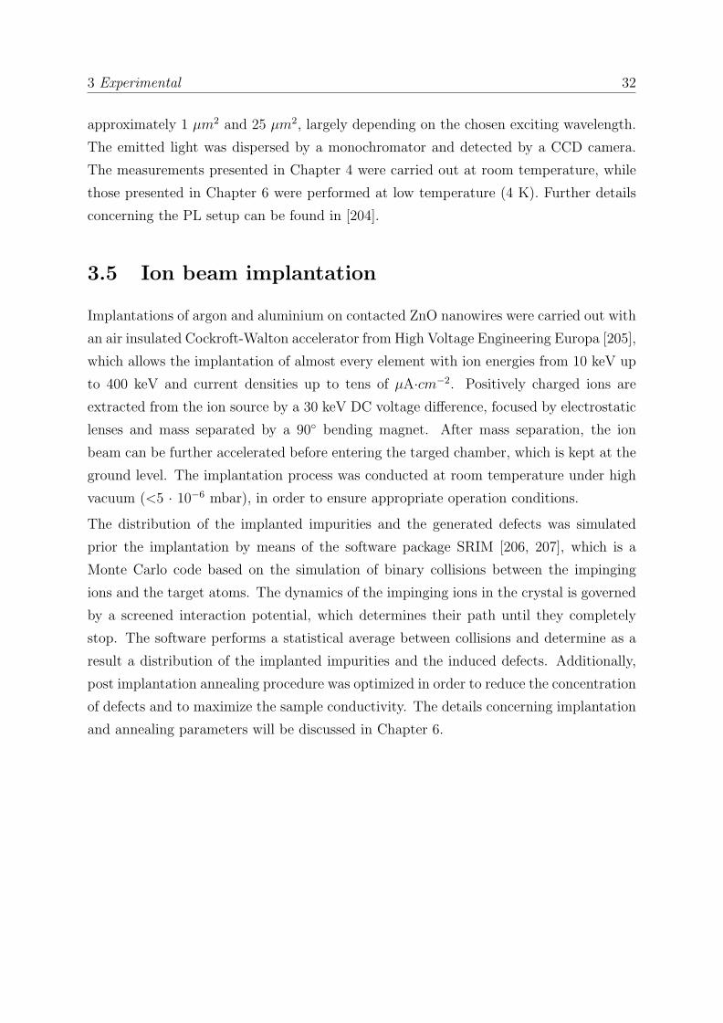
3.5 Ion beam implantation
Implantations of argon and aluminium on contacted ZnO nanowires were carried out with
an air insulated Cockroft-Walton accelerator from High Voltage Engineering Europa [205],
which allows the implantation of almost every element with ion energies from 10 keV up
to 400 keV and current densities up to tens of µA·cm−2. Positively charged ions are
extracted from the ion source by a 30 keV DC voltage difference, focused by electrostatic
lenses and mass separated by a 90 bending magnet. After mass separation, the ion
beam can be further accelerated before entering the targed chamber, which is kept at the
ground level. The implantation process was conducted at room temperature under high
vacuum (<5 · 10−6 mbar), in order to ensure appropriate operation conditions.
The distribution of the implanted impurities and the generated defects was simulated
prior the implantation by means of the software package SRIM [206, 207], which is a
Monte Carlo code based on the simulation of binary collisions between the impinging
ions and the target atoms. The dynamics of the impinging ions in the crystal is governed
by a screened interaction potential, which determines their path until they completely
stop. The software performs a statistical average between collisions and determine as a
result a distribution of the implanted impurities and the induced defects. Additionally,
post implantation annealing procedure was optimized in order to reduce the concentration
of defects and to maximize the sample conductivity. The details concerning implantation
and annealing parameters will be discussed in Chapter 6.

Chapter 4
Sub-bandgap photoconductivity in
ZnO nanowires
This chapter deals with the below band gap photoconductivity properties of ZnO nanowire
based field effect transistors. The initial investigation of the electrical properties of the
samples in dark condition is followed by the analysis of the photoresponse properties
in the range 400 - 800 nm. Particular attention is dedicated to the modulation of the
photoresponse, induced by the applied gate voltage. The electrical measurements are
accompagnied by a microphotoluminescence characterization, in order to gain deeper
insight about the nature of the defect involved in the photoconduction process. The
latter measurements were performed in collaboration with Rober Roder and part of the
results have been published in [208].
4.1 Motivation
It is well known that the presence of defect levels in a field effect transistors can drastically
affect several properties of such devices [209]. Defects can be located in the semiconductor
channel as well as in the gate dielectric and in the sustrates, or at different interfaces.
In particular, the impact on the transport properties can be particularly significant in
nanowire based FETs, due to the high surface to volume ratio of the semiconductor
channel.
In view of photodetection applications with ZnO nanowires, a detailed knowledge about
the nature of defect levels in related electronic devices is fundamental. On the one hand,
the presence of defect can be deleterious, leading for instance to device instabilities and
degradation. Moreover, it can be deleterious in applications for which visible-blind ZnO
33

4 Below band gap photoconductivity in ZnO nanowires 34
photodetectors are required. On the other hand, it may be convenient whenever the
extension of the photosensitivity range in sub-bandgap spectral range is desirable.
From this perspective, the FET configuration is particularly convenient, since it offers the
opportunity to control the occupation of defect levels by means of electric gating. In this
way, it is possible to selectively detemine wheter a defect level is available or not for the
photoconduction process, allowing the development of flexible photodetectors, which can
operate as a visible-blind or as sub-bandgap sensitive devices depending on the specific
applied gate voltage.
4.2 Electrical properties of ZnO NW FETs in dark
4.2.1 Contact properties
As introduced in section 2.3, the dependence of the drain-source current on the corre-
sponding voltage difference reveals fundamental informations about the contact properties
of the device. Current – Voltage measurements (I-V) were performed in the range [-10
V;+10 V] on samples produced as described in 3.2, keeping the gate electrode grounded.
The curves related to single nanowire devices are typically characterized by a strongly non
linear profile, which indicates the formation of Schottky contacts. However, the Schottky
properties of the two contacted nanowire sides are not necessarely comparable, since the
mechanical imprinting of the nanowires on the substrate prior the photo-lithography is
a random process. Consequently, the I-V characteristics of a single nanowire device can
assume either a symmetrical or an asymmetrical profile, as evident in Figure 4.1 (a) and
Figure 4.1 (b) for two different devices. However, when the electrodes are bridged by a
higher number of nanowires, the I-V charateristics appear more linear, as a result of the
average between several non linear I - V curves (Figure 4.1 (c)).
The appearence of the S-shaped profile in the I-V characteristics of single nanowire de-
vices can be understood by modelling the contacted ZnO nanowire, which is basically a
metal-semiconductor-metal structure, as two back-to-back Schottky diodes. This choice
is motivated by the fact that the I-V characteristics of a diode are characterized exactly
the same rectifying properties of a Schottky contact. Basically, when an external voltage
difference is applied, the same current I must flow through both diodes. However, when
one diode (nominated for semplicity diode 1) is forward biased, the other one (diode 2)
is reversed biased. The latter tends consequently to limit the value of the current, which
tends to saturate. The same situation occurs obviously in the opposite interval of the

4 Below band gap photoconductivity in ZnO nanowires 35
voltage difference. This explains qualitatively the observed behaviour. Quantitatively,
the current which would flow through a single diode can be written as:
I1,2 = A∗T 2e−φ1,2kT (e
eVkT − 1) (4.1)
where φ1,2 are the respective potential barrier at the two interfaces. Imposing that I =
I1 = I2, the total current can be expressed as [210]:
I =I01I02sinh(eV/2kT )
I01exp(eV/2kT ) + I02exp(−eV/2kT ), (4.2)
where I01 = AT 2exp(φ1/kT ), I01 = AT 2exp(φ2/kT ) and φ1,2 are the Schottky barrier
heights. The other quantities are definited as previously. An example of fitting using
equation 4.2 is presented in Figure 4.1 (a), in case of two comparable barriers heights.
The discrepancy observed at low bias originates most probably from the non complete
idealy of the diodes [210], which is not taken into account in equation 4.2. The obtained
values of the two Schottky barrier φ1 and φ2, which are around 0.45 eV, are comparable
to that reported in literature for similar ZnO nanowire devices [211].
However, the nature of the Au/Ti/ZnO junction is still matter of debate in literature.
While some studies report about the formation of a Schotthy barrier [212], some others
reveal ohmic properties [32, 213]. In general, a univocal determination of the nature of
such junction is not possible, due to the similarity of the work function of Ti and the elec-
tron affinity of ZnO. In particular, the reported values of the ZnO electron affinity range
from 3.7 up to 4.5 eV [214, 215]. As such, depending on the specific conditions, it can be
higher or lower than the work function of Ti (4.33 eV [216]) and the corresponding junc-
tion might show respectively ohmic or Schottky characteristics. Additionally, depending
on the Ti thickness, the presence of Au (φ = 5.1 eV [216]) in the proximity of the Ti/ZnO
interface can lead to a further mixing of the junction properties. Furthermore, even while
dealing with the same nominal semiconductor, several factors such as growth conditions
and sample preparation can lead to incomparable results in terms of junction properties.
In particular, different growth techniques and growth conditions give typically rise to dif-
ferent concentration of unintentional dopants and determine therefore dissimilar contact
characteristics. Also the roughness of the semiconductor surface critically depends on
the processing steps required for the sample preparation and can drastically affect the
features of the interface.
A final comment concerns the influence of the source-drain bias polarity on the density of
occupied defect levels in the proximity of the contact regions. In general, the occupation

4 Below band gap photoconductivity in ZnO nanowires 36
Figure 4.1: Current - Voltage measurements (I - V) performed on ZnO nanowiredevices (compare figure 3.2) with different contact properties. Single nanowire devicesshow typically nonlinear characteristics due to the formation of a Schottky contact be-tween ZnO and the Ti/Au electrodes. The height of the Schottky barriers on the twocontacted sides of the nanwire can be comparable (a), or considerably differs (b), re-sulting in a symmetric or asymmetric profile of the I- V characteristics, respectively.When the electrodes are bridged by more nanowires the curve is almost linear (c), being
the average between several asymmetric contributions.
probability of a defect level varies in the depletion region, since its position changes in
respect to the Fermi level [217]. Since the application of an external bias modifies the
original width of the contact depletion region and the profile of the corresponding band
bending, the occupation probability of defect levels near the contact region will change
correspondingly. In case of contacted nanowires with symmetric I-V characteristics, no
matter whether linear or not, it is expected that an inversion of the bias polarity does
not affect significantly the total density of occupied defect levels, since the drain and
the source contacts are characterized by comparable properties, as previously discussed.
However, this is not true when the I-V characteristics are highly asymmetric. In this
case the properties of the source and drain contacts significantly differ and the density of

4 Below band gap photoconductivity in ZnO nanowires 37
Figure 4.2: Transfer characteristics (Ids–Vgs) of a single ZnO NWFET, measured atVds = + 5 V in air and dark conditions (a). A large hysteresis is appreciable, whichappears when the voltage is sweept at first from negative toward positive values (1) andthen backwards (2). The effect of a bias conditioning on the transfer measurements isshown in (b). Conditioning at Vgs = - 50 V for 1 hour prior the measurement induces anegative shift in the gate voltage threshold, whiel the occposite occurs after a conditioning
at Vgs = + 50 V. In the former case also a larger hysteresis can be appreciated.
occupied level at a specific bias may be correspondingly uncomparable with that occurring
under opposite bias polarity. This fact must be always taken into account, while dealing
with the transport properties of such nanowire devices.
4.2.2 Transfer characteristics
Since the conductivity of n- and p-type semiconductors shows an opposite dependence
on an external gate potential, transfer characteristic measurements (Ids - Vgs) represent
a suitable tool, in order to determine the nature of charge carriers in the semiconductor
channel. For this purpose, transfer characteristics were measured in air on single nanowire
FETs in the gate voltage range [-50 V;+50 V]. A typical measurement, presented in Figure
4.2 (a), shows that the nanowire channel is fully depleted when the the gate voltage is
lower than a threshold value, above which the conductivity progressively increases. This
result conferms that the investigated ZnO nanowires nanowire are as expected intrinsically
n-type doped, as also revealed by previous studies [22, 86, 94–96]. Additionally, a large
hysteresis can be observed when the voltage is sweept at first from negative toward
positive values and then in the opposite direction.
However, both the voltage threshold and the hysteresis cannot be univoquely determined,
as they can be for instance affected by a gate bias conditioning, which consists in the

4 Below band gap photoconductivity in ZnO nanowires 38
Figure 4.3: Temporal dependence of Ids in a single ZnO NW FET after changingVgs from 0 V toward positive (a) or negative (b) voltage values. In the former casethe current increases quickly, but then decreases gradually. The opposite occurs in the
latter case.
application of a constant Vgs for an extended time prior measuring the transfer char-
acteristics. As shown in Figure 4.2 (b), a positive bias conditioning induces a positive
shift of the threshold voltage and a reduced hysteresis, while the opposite occurs after
a negative bias conditioning. The conditioning was performed in the former and latter
case by keeping the voltage respectively at Vgs = + 50 V and Vgs = - 50 V for one hour
prior the measurement. This indicates that the current Ids is not exclusively determined
by the gate voltage value but is also affectect by the previous gating history. Moreover,
instability of the drain-source current was observed in the investigated samples by mea-
suring Ids as a function of the time during a prolonged gating. Specifically, the change
in Ids induced by a sudden variation of Vgs tends to partially dissipate over the time,
as shown in Figure 4.3 in case of positive and negative gating variations. Ids was also
measured four times consecutively as a function of the time, three times in air and once
in argon, changing Vgs from 0 V to - 50 V. At the end of every measurement Vgs was
switched again to 0 V and left for 10 min at this value of the gate voltage before starting
the following measurement. A progressive decrease of the current saturation is observed
from the first to the last measurement, but this trend is not significantly affected by the
atmosphere conditions, as shown in figure 4.4.
Gating instabilities effects and the appearence of transfer hysteresis have been already
observed in ZnO based transistors and mainly attributed to the charging and discharging
of interface trap levels [218, 219] or to polarization effects induced by adsorpbed molecules
[86, 139]. Since no dependence on the surrounding atmopshere has been observed, the

4 Below band gap photoconductivity in ZnO nanowires 39
Figure 4.4: Repetition of the same measurement presented in Figure 4.3 in case ofVgs = -50 V for four times consecutively, three times in air and once in argon. Aprogressive decrease of the saturation current is observed, not related to the atmosphere
conditions.
former process seems to be predominant in the sample investigated within this work. The
corresponding mechanism is based on the electrostatically induced attraction or repulsion
experienced by electrons respectively toward or from interface levels, located between the
substrate and the SiO2 layer or between the SiO2 and the ZnO. Depending on the sign
of the gate potential, this results in the progressive formation of positively or negatively
charged interface layers, which partially screen the gate field and lead the appearence of
the above presented effects. Furthermore, the gating-driven accumulation or depletion
of electrons in the proximity of the source and drain contact regions may also determine
the occurrence of charging/discharging processes at defect levels, which eventually lead
to a local change of the contact Schottky barrier, with corresponding slow variation of
Ids [220].
Such instabilities are not necesserely deleterious for the performance of FETs, as they
can be for instance positively exploited for the development of non-volatile memories
[221, 222]. As such, attempts have been made, in order to achieve a reliable control of the
hysteresis. These includes for instance the use of gate dielectrics with superior trapping
ability, such as Al2O3 [223], or procedures for the generation in the substrate of mobile
charges, which can be easily trapped and detrapped from interface states. For the latter
purpose, annealing treatments in hydrogen atmospehres [218] and hydrogen implanta-
tion [198] have been succesfully exploited. Furthermore, controlling the population of

4 Below band gap photoconductivity in ZnO nanowires 40
interfacial levels by means of electric gating can be employed in order to modulate the
photoconductiviy of nanowire-based FETs under sub-bandgap excitation.
4.3 Gate voltage modulation of photoresponse
The below band gap photoconductivity of ZnO NW FETs was investigated considering
single nanowire devices with strongly asymmetric I-V characterisitcs, such as in Figure
4.1 (a), in order to simultaneously evaluate the influence of the gate voltage and that of
the source-drain bias on the optical activity of defect levels.
The photoresponse was at first studied under negative gating (Vgs = - 50 V) in the range
from 400 to 800 nm, in steps of 40 nm. The measurements, shown in Figure 4.5 (a), were
conducted initially at Vds = + 5 V, switching Vgs from 0 V to - 50 V immediately before
starting the data acquisition at t = 0 s. The light excitation was then switched on at t
= 5 s. At the end of every measurement Vgs was switched back from -50 V to 0 V and
left at this gate voltage value for 1 min before starting the following measurement with
a different exciting wavelength. Additionally, a reference measurement in the dark was
performed under the same experimental conditions.
No increase of Ids was observed in the investigated temporal interval (200 s) with exciting
wavelength longer than 640 nm. Only with shorter wavelength an onset of the pho-
tocurrent increase appears, untill the current saturates in all investigated cases sligthly
below 100 pA. The onset is not immediate and the activation time required to observe
it decreases progressively with shorter wavelength. The photoconductivity response was
then investigated at gate voltage Vgs = 0 V and Vgs = + 50 V under illumination at
550 nm. For the measurement at Vgs = + 50 V, the same procedure considered for the
previous measurements at Vgs = - 50 V was adopted. In both cases, no photoresponse
was observed, as can be seen in Figure 4.5 (b).
The measurement performed at Vgs = - 50 V under illumination at 550 nm was also
compared on a larger time scale with that carried out in dark conditions, in order to
compare the rise of the photocurrent with the slow gating-induced instablilites in Ids
described in the previous section. As shown in Figure 4.6, the photocurrent and the dark
current saturate at comparable values. However, the onset of the current increase and
the time required to reach the saturation are much reduced under light excitation. This
indicates that the charge trapping/detrapping processes occurring at interfacial states
or near the contacts, which are responsible for the slow increase of the dark current

4 Below band gap photoconductivity in ZnO nanowires 41
Figure 4.5: Ids as a function of the time in a single ZnO NW FET under below-band-gap excitation in the range 400-800 nm, in steps of 40 nm, at Vgs = -50 V (a). In allmeasurements the photocurrent saturates at similar values. The device does not showany response under photo-excitation at wavelength longer than 640 nm. An equivalentmeasurement is repeated at Vgs = 0 V and Vgs = +50 V under photoexcitation at 550
nm (b). In both cases no photoresponse is observed.
at negative gate voltages, must be effectively involved also under photoexcitation below
band gap.
Analogous measurements under photoexcitation at 450 nm and 550 nm were performed
also at reversed source-drain bias (Vds = - 5 V). In view of what pointed out in the
conclusions of the previous section, a significant difference in terms of photoresponse is
to expect, if the defect levels in the proximity of the contact regions play a major role
in the photoconduction process. However, as shown in Figure 4.7, the obtained results
are comparable with that reported in case of Vds = - 5 V, since photocurrent is measured
only at Vgs = - 50 V, but not under positive gating. This indicates that the eventual
charge/discahrge processes occurring in the proximity of the source and the drain contacts
are substantially not responsible for the appearence of the sub-bandgap photoresponse
under negative gating.
The eventual contribution of other defect levels, located in the core of the nanowire, was
investigated by means of microphotoluminescence measurements. Such measurements
were performed at room temperature in the regime of low excitation density, in order to
maximize the deep level emission (DLE) intensity and to avoid defect saturation effects
[204]. At room temperature, the diffusion length of the exciton in ZnO is in the range of
the NW diameter [224] and it is therefore more likely that the excitons are captured at
defects, rather than reaching the surface or the SiO2/ZnO interface. Consequently, the
contribution to the photoluminescence signal from the defects located in the core of the

4 Below band gap photoconductivity in ZnO nanowires 42
Figure 4.6: Direct comparison of Ids as a function of time under sub-bandgap excita-tion at 550 nm and in dark conditions at Vgs = -50 V. The current saturates in bothcases at similar values. However, the temporal onset of the current increase is much
reduced under photoexcitation.
nanowire is expected to be dominant compared to the emission originating from surface
or interface levels.
The sample was connected to the same electrical generators, in order to reproduce the
same experimental conditions as for the electrical measurements and the spectra, shown
in Figure 4.8, were measured at gate voltage Vgs = 0 V, immediately after switching to Vgs
= -50 V and after 1 and 2 minutes of prolonged gating at Vgs = -50 V. It can be clearly
observed that in all investigated cases the change in the gate voltage does not induce
any appreciable change of the DLE, which is typically related to defect levels located
in the band-gap of ZnO [204]. Therefore, the result of the µPL measurements strongly
suggest that the change in the gate voltage does not induce any appreciable variation in
the population of defect levels located in the nanowire volume.
This result corroborates the original hypothesis that the switching of the gate voltage
toward negative values induces substantially only a variation of the interfacial level oc-
cupation. Furthermore, the observation of photoresponse at Vgs = - 50 V but not at Vgs
= 0 V and Vgs = + 50 V, implies that only a negligible density of interfacial levels are
occupied under positive gating. On the contrary, other authors have instead observed
enhancement of the below band gap photoconductivity under positive gating, as a result
of photoexcitation of occupied interfacial levels [225, 226]. In principle, a positive gating

4 Below band gap photoconductivity in ZnO nanowires 43
Figure 4.7: Ids as a function of the time in a single ZnO NW FET under photoexcita-tion at 450 nm and 550 nm and reversed polarity of the drain-source bias (Vds = -5 V).Measurements were performed at Vgs = - 50 V (a), Vgs = 0 V (b) and Vgs = + 50 V(c). As already observed in the measurements performed at Vds = +5 V, photoresponse
occurs only under negative gating.
should induce electron accumulation in ZnO close to the interface with the SiO2 [225], fa-
voring consequently the filling up of such levels. However, whether this process effectively
occurs depends on the effective gate voltage experienced by the semiconductor channel
in the proximity of the interface, which critically depends on the screening determined
by the gate dielectrics. Since the oxide layer of the FETs produced in the frame of this
thesis was at least 4 times thicker than that employed in [225, 226], a stronger screening
of the gate field is expected in the proximity of the SiO2/ZnO. This might consequently
hinder the electron trapping from the ZnO toward interface.
The trapping process must therefore proceed in the opposite direction, involving electrons
which are already available in the oxide layer. It is well known that electrons can be
localized in the gate dielectrics at bulk defect states [209] and at the interface with the
substate [227–229]. Under a negative gating these can be repelled toward the interface

4 Below band gap photoconductivity in ZnO nanowires 44
Figure 4.8: µPL spectra of a single ZnO NW FET in the spectral region of the deep-level-emission, at Vgs = 0 V and Vgs = -50 V. The change of the gate voltage does notinduce any appreciable change in the defect-related emission, which is dominating the
spectra.
with the nanowire and there being trapped, as illustrated in Figure 4.9. Since such
electron migration is expected to be a slow process, an activation time is most propably
required in order to fill the interfacial levels. This might explain the non immediate onset
of the photoresponse observed during the photoconductivity measurements.
Despite the uncertain origin of the migration mechanisms in the gate dielectric and the
interfacial levels involved in the photoconduction process, the observed results clearly
indicate the possibility to succesfully modulate the below band gap photoresponse of
ZnO NW FETs by means of electric gating. The intentional generation of further defects
at the interface SiO2/ZnO interface, succesfully reported for instance in case of proton
irradiation [230], can be in principle exploited for enhancing and tuning the photoresponse
properties of similar nanowire based devices.
On the other hand, the measurements performed reveals that the density of defects in
the core of the nanowire is too low, in order to contribute to the photoresponse. Further
strategies, including for instance modification of the nanowires by means of ion beam
implantation, should be therefore explored, in order to selectively increase the density
of optically active defects in the semiconductor channel. A stronger involvment of the
nanowire channel in the photoresponse mechanism would be highly beneficial for the

4 Below band gap photoconductivity in ZnO nanowires 45
Figure 4.9: Schematic model describing the influence of the electric gating on thesub-bandgap photoresponse properties of a single ZnO NW FET. At Vgs = 0 V in-terfacial levels between the SiO2 and the ZnO are not occupied and photorsponse isconsequently not observed (a). Under negative gating migration of electrons from even-tual subtrate/dielectric or dielectric defect states may occurs, leading to the charging ofSiO2/ZnO interfacial states and the correpondingly to the observed photoconductivity.
development of faster sub-bandgap photodetectors, since the gating-induced emptying
and occupation of defect levels in ZnO is expected to proceed faster than in SiO2. As a
result, a significant reduction of the temporal onset required to observe the photoresponse
is to expect.
4.4 Conclusions
In this chapter the sub-bandgap photoconductivity properties of ZnO nanowire field-
effect-transistors (NW FETs) have been investigated. The FET configuration is exploited,
because it offers the possibility to control the occupation of defect levels by means of elec-
tric gating. Consequently, the photoresponse of such devices can be tuned according to
the desired photodetection applications, allowing the development of flexible photodetec-
tors based on ZnO nanowires.
At first, the electrical properties of the NW FETs in dark conditions have been presented
and discussed. Current - voltage measurements (Ids − Vds) reveal the Schottky nature
of the source and drain contacts. Transfer characteristics (Ids − Vgs) confirm that the
ZnO nanowire channel behaves as expected as an n-type semicondutor, showing electron

4 Below band gap photoconductivity in ZnO nanowires 46
depletion or accumulation under respectively negative or positive gating. However, sig-
nificant gating instability effects have been observed, including the slow dissipation of
the current change induced by a sudden variation of the gate voltage or the influence
of a gate bias conditioning on both gate voltage threshold and transfer hysteresis. Such
effects have been attributed to the charging/discharging of defect states located at the
interface SiO2/ZnO.
Sub-bandgap photoresponse has been observed in the range 400 - 800 nm under negative
gating (Vgs = - 50 V), while no reaction occured at positive gate voltage. The photocur-
rent tends to saturates approximately at the same value independently on the exciting
wavelength. However, the onset of the photresponse requires an activation time, which
progressively decreases as the exciting wavelength decreases. The obtained results are
substantially independent on the drain-source bias polarity.
Photoluminescnece measurement reveal additionally that changes in the gate voltage do
not induce any appreciable variation in the population of defect levels located in the
nanowire volume. This indicates that the same interfacial levels, which are responsible
for the gate instabilites in the dark current, are involved also in the photoconduction
process.

Chapter 5
Persistent photoconductivity in ZnO
nanowires
This chapter deals with the persistent photoconductivity observed in ZnO nanowires after
above band gap excitation. The study is focused in particular on the influence of different
surrounding environments on the photoconduction process, as well as on the dependence
of the photocurrent decay on the light excitation power. A fitting procedure based on the
kinetics of the oxygen adsorption process is then discussed. Part of the results presented
in this chapter have been published in [39].
5.1 Atmosphere dependence of the persistent photo-
conductivity
If the persistence of the photoconductivity is related to the properties of the nanowire
surface, a dependence of the photo-current decay on the surrounding environment must
be expected. Photoconductivity measurements in different atmospheres were therefore
performed, in particular in air, under flow of inert gases (nitrogen and argon) and at low
pressure (10−5 mbar). For this purpose, several single nanowire devices were selected and
their electrical properties investigated.
The I-V characteristics of a typical sample are shown in Figure 5.1 as a function of
different environments and UV excitation. In dark, the value of the current in nitrogen,
argon and air is substantially comparable in the investigated voltage range, while it is
around one order of magnitude lower in vacuum. Upon UV light excitation in steady
47

5 Persistent photoconductivity in ZnO nanowires 48
Figure 5.1: Current-voltage (I-V) characteristics of a single ZnO NW device in dif-ferent environments. The photosensitivity of the nanowires to UV excitation is clearly
appreciable, with a particularly pronounced change under vacuum conditions.
state conditions the conductivity is at least three orders of magnitude higher than in
dark, with a particularly pronounced change under vacuum conditions.
The photocurrent as a function of time increases initially quickly under all atmosphere
conditions (Figure 5.2 (a)), especially in air, as shown in Figure 5.2 (b). The increase
rate slows down progressively and a saturation is reached within one hour in air, nitrogen
and argon. The rate reduction is instead less pronounced in vacuum, in which the pho-
tocurrent increases approximately linearly with the logarithm of the time. The observed
photoresponse can be quantitatively expressed in terms of photoresponsivity R, which
is defined as the ratio between the steady state photocurrent and the excitation power
absorbed by the nanowire Pabs,NW [63]:
R =∆I
Pabs,NW. (5.1)
Pabs,NW can be calculated in terms of the nanowire lateral area (ANW ), light intensity
(Iexc), reflectivity (R) and absorption coefficient (α) of ZnO at 370 nm, as Pabs,NW =
IexcANW (1 − R)(1 − e−αd), where d is the nanowire diamater. The lateral area of the
nanowire can be approximated as ANW ≈ d · l, with d = 200 nm and nanowire length
l= 5 µm. Assuming R = 0.1 and α = 105 cm−1 [231], Pabs,NW ≈ 10−11 W. The values of
the photocurrent are Iph = 5 ·10−6 A in air, argon and nitrogen and Iph = 1.5 ·10−5 A in
vacuum. Correspondingly, the responsivity in air, argon and nitrogen is estimated as:
R ≈ 5 · 105 A
W, (5.2)

5 Persistent photoconductivity in ZnO nanowires 49
Figure 5.2: Increase of the photocurrent in a single ZnO nanowire device as a functionof the time in different environments (a). The current saturates within two hours inair, argon and nitrogen, but not in vacuum. In the latter case the photocurrent increaseslogarithmically with the time, as shown by the corresponding fitting function. (b) showsa magnification of (a), when the UV light is switched on. The photoresponse is initially
stronger in air than in other atmospheres. The measurements were performed atVds = +5 V.
while in vacuum:
R ≈ 1.5 · 106 A
W. (5.3)
The obtained values are comparable with that observed by other authors in similar ZnO
nanowire devices [232–235] and confirm the enormeous potentialities of ZnO nanowires
as building blocks for photodetection applications.
After light excitation the photocurrent decays faster in air than in other environment
conditions, as shown in Figure 5.3 (a). A significant drop of the conductivity is observed
under vacuum conditions and in the inert atmospheres as soon as air is let into the
chamber. However, a gradual slowdown of the decay rate occurs few seconds after letting
in air, as particularly evident in Figure 5.3 (b).
The photocurrent was then measured as a function of the exciting wavelenth, in order to
determine the nature of the charge carriers involved in the photoconduction process. For
this purpose, the Xenon Lamp was used as a light source in the spectral range between
300 and 900 nm. The measurement was carried out in air, by scanning the spectral range
in steps of 5 nm and keeping the light excitation on for 5 s during every step. As shown in
Figure 5.4, a sharp onset of the photocurrent increase is observed around 375 nm, which
corresponds to the band gap of ZnO. The decrease of the photocurrent above 350 nm is

5 Persistent photoconductivity in ZnO nanowires 50
Figure 5.3: Photocurrent decay in a single ZnO nanowire device in different environ-ments after removing the UV excitation; (b) shows a magnification of (a), when air islet into the chamber. The decay rate increases considerably, but then progressively slows
down. The measurements were performed at Vds = +5 V.
caused by the reduced light intensity in this spectral region of the used lamp. Since no
photoresponse is observed at wavelength longer than 375 nm, the overall photoconduction
process can be attributed to the generation of electron-hole pairs from the valence band
to the conduction band, with negligible contribution from defect state levels.
However, the direct contribution of free electron-hole pairs to the photocurrent can be
substantially neglected, as proved in the following by comparing the experimental pho-
tocurrent with that expected under the assumption that all photogenerated electron - hole
pairs contribute to the photoconductivity. The latter assumption presupposes that all
photogenerated charge carriers remain free during the photoconduction process, namely
that their lifetime is not longer than 1 ns.
Under steady state excitation conditions, the density of free electron-holes pairs ∆nph is
related to their lifetime τ and to the carrier photogeneration rate G through the following
expression [152]:
∆nph = τ ·G. (5.4)
The photogeneration rate can be expressed as G = Pabs,NW/(Eg · VNW ), where Eg is the
band gap of ZnO and VNW ≈ 2 · 10−13 cm3 is the nanowire volume. Thus:
G ≈ 1020 s−1 · cm−3. (5.5)

5 Persistent photoconductivity in ZnO nanowires 51
Figure 5.4: Photoresponse of a single ZnO nanowire device as a function of the ex-citing wavelength. A clear onset is observed for wavelength shorter than 375 nm, whichcorresponds approximately to the band gap of ZnO. The measurement was performed in
air at Vds = +5 V.
Considering τ ≈ 1ns, the density of free electrons-hole pairs is estimated to be ∆nph ≈1011 cm−3. This corresponds to the photocurrent:
Iph = S · e · µ · E ·∆nph ≈ 1 pA, (5.6)
assuming a nanowire cross section S = (d/2)2π ≈ 10−9 cm2, an electron mobility µ ≈ 20
cm ·V −1 ·s−1 [37] and an electric field between the electrodes E = 5 V/5 µm = 104 V/cm.
The calculated value of the photocurrent is clearly much lower than the experimental
ones, which is in the order of few µA in all considered environments. The large dis-
crepancy reveals therefore that the lifetime of the photogenerated charge carriers must be
significantly longer than 1 ns. This reflects a reduction of the electron-hole recombination
probability, which can be caused by the trapping of either electrons or holes, which leave
free umpaired charge carriers with prolonged lifetime. Since previous Hall measurements
revealed that the photoconductivity in ZnO is determined by photogenerated electrons
[236], hole trapping mechanisms must be effective. Among these, hole trapping at surface
states is most likely dominant, since the dynamics of the photocurrent increase depends
on the environment conditions. In particular, the evidence that the photocurrent rises
initially faster in air than in vacuum, indicates that oxygen adsorbed species promote

5 Persistent photoconductivity in ZnO nanowires 52
such surface trapping process. These results are in accordance to that obtained by Mel-
nick [164] and attributed to the migration of holes toward the surface, induced by the
ionosorbed-oxygen related surface band bending (Figure 5.5 (a)).
Furthermore, the logaritmic dependence of the photocurrent increase over the time ob-
served in vacuum suggests that the photocurrent increase is accompanied by a pho-
todesortion process, since the photodesorption from semiconductor surfaces is typically
characterized by a logaritmic kinetics [237]. This further supports the original intuition
of Melnick, according to which ionosorbed oxygen is desorbed from the surface as a result
of the recombination between trapped electrons and holes accumulated at the surface.
The desorption process leaves consequently a certain fraction of umpaired photogener-
ated electrons in conduction band with the required prolonged lifetime. More quantitative
considerations about this point will be discussed in section 5.2. The fact that such logar-
itmic dependence is clearly observed only in vacuum, suggests that the oxygen desorption
occurs more effectively at reduced pressure than in other atmosphere conditions. This ap-
pears reasonable, because the release of oxygen species can be hindered at higher pressure
by the enhanced collision rate with other gas molecules in the proximity of the surface,
resulting in a lower net desorption rate.
Since the density of adsorbed oxygen is progressively reduced during the photoconducton
process, it is likely that oxygen molecules tend to readsorb on the nanowire surface after
stopping the illumination, in order to recover the oringinal equilibrium coverage. Fur-
thermore, it is expected that, due to its high electronegativity, the oxygen readsorption
is accompanied by the simultaneous trapping of photogenerated electrons at the surface
and correspondingly by a decrease in the nanowire conductivity (Figure 5.5 (b)). This
explains the observed drop of the photocurrent as soon as air is added to an oxygen
poor atmosphere. However, the progressive accumulation of electrons at the surface is
responsible for a gradual increase of the surface electrostatic potential, which hinders fur-
ther adsoprtion and determines consequently the observed slowdown of the photocurrent
decay rate.
A more detailed description of such recombination mechanism requires however a quanti-
tative analysis of the temporal evolution of the photocurrent decay, including in particular
its dependence on the photogenerated charge carrier density. The determination of an ap-
propriate fitting function, which can realistically describe the adsorption-assisted electron
trapping, permits in particular to overcome the limitation of previously proposed analysis
procedures, which typically lack a reliable underlying physical model. Additionally, it al-
lows to evaluate the weight of such recombination mechanism on the overall photocurrent

5 Persistent photoconductivity in ZnO nanowires 53
Figure 5.5: The photo-generated electrons and holes in a ZnO nanowire are separatedby the built-in electric field, induced by ionosorbed oxygen (a). The charge carrier life-time is thus increased, determining a quick rise of the photoconductivity. After illumi-nation oxygen molecules readsorb and trap simultaneously electrons from the conductionband, causing the observed drop of the photoconductivity (b). This model correspondsto that proposed by Melnick in case of porous sintered ZnO [164]. In both figures, thecolor of photogenerated charge carriers is blue, whereas other electrons in the conduc-tion band determine the intrinsic n-type conductivity of ZnO and are indicated in black.
The green arrows describe the re-trapping of electrons and the oxygen readsorption.
decay, revealing the eventual partecipation of other eventual relaxation processes. These
aspects will be widely discussed in the next section.
5.2 Dynamics of the photoconductivity decay
The results presented in the previous section indicate qualitatively that after above band
gap excitation photogenerated electrons tend to be trapped at the surface during the
simultaneous readsoprtion of oxygen molecules at the nanowire surface. This hyphotesis
can be quantitatively discussed by comparing the temporal dependence of the photocur-
rent decay with the kinetics of the oxygen adsorption process. Indeed, if the adsorption
of oxygen molecules causes the simultaneous trapping of photogenerated electrons at the
surface, both processes should be characterized by the same time dependence.
Although the kinetics of oxygen adsorption on ZnO was not experimentally investigated
in the frame of this thesis, previous studies revealed that it can be accurately described by
the so called Elovich equation, which is widely employed for the description of adsorption
processes on solids [238]. In its differential form, the Elovich equation is expressed as:
dq
dt= a · e−bq, (5.7)

5 Persistent photoconductivity in ZnO nanowires 54
where q is the density of adsorbed molecules and a and b are constants, which represent
respectively the initial adsorption rate and the rate of change of the adsorption energy
with the coverage [188]. The integral form of equation 5.7 is given by:
q =1
b· ln((ab)t+ 1). (5.8)
In view of the previous considerations, equation 5.8 can be exploited to describe also the
temporal evolution of the electron trapping at the surface. Assuming the latter as the only
effective recombination mechanism, the density of electrons in conduction band during
the photocurrent decay is ncb,Elov(t) = nph − ntr,Elov(t), where nph is the photoelectron
density maximum and ntr,Elov(t) is the density of trapped electrons. The latter quantity
can be expressed in terms of q, taking into account that it represents a volume density,
while q is a surface density:
ntr,Elov(t) = q · SNWVNW
, (5.9)
where SNW and VNW are respectively the nanowire lateral area and volume. Therefore:
ncb,Elov(t) = nph −SNWVNW
· 1
b· ln((ab)t+ 1), (5.10)
Within this approximated model, in which all other eventual recombination mechanisms
are not considered, the photocurrent decay is consequently expressed as:
IElov(t) = S · e · µ · E · ncb,Elov(t) = S · e · µ · E · (nph −SNWVNW
· 1
b· ln((ab)t+ 1)). (5.11)
Equation 5.11 represents the required fitting function for the evaluation of the photocur-
rent decay in terms of the adosorption-assisted electron trapping. Since it includes the
generated photocurrent maximum nph as a parameter, it is particularly suitable for the
analysis of the photocurrent decay as a function of the excitation intensity.
For this purpose, photoconductivity measurements were performed in air under different
excitation intensities, ranging from 20 µW/cm2 up to 5 mW/cm2. During every mea-
surement, the current was initially measured in the dark for 60 s, then the samples were
illuminated for 5 s and the photocurrent decay was recorded until the original dark cur-
rent was completely recovered. The decay curves are shown in Figure 5.6 (a), in which

5 Persistent photoconductivity in ZnO nanowires 55
Figure 5.6: Photocurrent decay in a single ZnO nanowire device after light excitationat various intensities (a). The measurements are plotted immediately after removingthe illumination, which lasted for 5 s. The generated photocurrent maximum, Iph,increases approximately linearly with the excitation intensity (b). The measurements
were performed in air at Vds = +5V .
the photocurrent I(t) - Idark is plotted as a function of the time immediately after re-
moving the illumination at t = 0. The maximum generated photocurrent Iph increases
approximately linearly with the excitation intensity, as evident in Figure 5.6 (b).
The experimental decay curves were fitted with equation 5.11, leaving only the constant b
as a fitting parameter without constrains. The other parameters, a and nph, were instead
determined prior fitting procedure.
The initial adsorption rate after illumination, a, was calculated in terms of the experi-
mental rate of the photoelectron density decay. In principle, these two rates do not nec-
essarely correspond, since it is not evident a priori that the adsorption-induced electron
trapping is the unique mechanism responsible for the initial decay of the photocurrent. It
is therefore necessary to quantify the weight of additional recombination mechansims to
the initial part of the photocurrent decay in air, by comparing the decay rate observed in
air,dI
dt air, t=0, with that observed under inert atmosphere,
dI
dt inert, t=0. For this purpose,
considering as a reference the measurements presented in section 5.1, both rates were
determined as the slope of a linear function, which can fit the photocurrent decay within
few seconds after removing the illumination (Figure 5.7). As shown in the same figure,dI
dt air, t=0was determined to be approximately 10 times higher than
dI
dt inert, t=0. However,
it must be taken into account that air residuals were present in the chamber while mea-
suring under inert atmospheres. The air residual concentration immediately after light
excitation was quantified as the ratio between the total volume of inert gas flowing in
the chamber and the original air volume prior introducing the gas, which corresponds

5 Persistent photoconductivity in ZnO nanowires 56
Figure 5.7: Comparison between the photocurrent decay rate in a single ZnO nanowiredevice in air and in argon atmosphere. The dashed lines represent linear fitting func-
tions, which fit the curves within few seconds after removing the illumination att = 0 s. The measurements were performed at Vds = +5V .
obviously to the volume of the chamber. The total volume of inert gas was calculated as
Vtot = Fg · t, where Fg is the gas flow and t = 4 hours, which accounts for the temporal
interval between letting the gas into the chamber prior the measurement (see section 3.3)
and removing the UV illumination (see Figure 5.2). Considering the values of the cham-
ber volume and the gas flow reported in section 3.3, the air concentration was estimated
to be 8 times lower than that of the inert gas. The ratio betweendI
dt inert, t=0and
dI
dt air, t=0
and that between the air residual concentration and the inert gas concentration are there-
fore substantially comparable. This strongly suggests that the initial photocurrent decay
in argon or nitrogen is mainly caused by adsorption-assisted electron trapping, induced
by residuals of oxygen in the chamber. Therefore, compared to the latter process, the
weight of additional recombination mechansims to the initial part of the photocurrent
decay in air must be significantly lower than 10 % and can be consequently neglected.
As such, when the measurement is performed in air, the initial adsorption rate a can be
approximated to the initial rate of the photoelectron density decay:
a ≈ dncbdt t=0
=1
SeµE· dIdt t=0
, (5.12)
where ncb is the electron density in the conduction band and the other quantities are
defined as in the previous section.

5 Persistent photoconductivity in ZnO nanowires 57
Table 5.1: Numerical values of the parameters contained in equation 5.11, whichwas used for fitting the photocurrent decay in ZnO nanowire devices. a and nph weredetermined prior fitting procedure, while b was obtained as fitting parameter without
constrains.
ExcitationIntensity
a (cm−2s−1) b (cm2) nph (cm−3)
20 µW/cm2 5·106 ± 105 2·10−7 ± 10−9 6·1012 ± 1010
300 µW/cm2 2·109 ± 108 7·10−9 ± 10−11 1.6·1014 ± 1013
1 mW/cm2 3·1010 ± 109 2·10−10 ± 10−12 6.2·1015 ± 1014
5 mW/cm2 4·1011 ± 1010 2·10−11 ± 10−12 6.7·1016 ± 1014
Finally, the electron density immediately after photoexcitation, nph, was calculated from
the experimental value of the photocurrent at t = 0, Iph:
nph =IphSeµE
. (5.13)
The obtained fitting parameters are summarized in table 5.1. These were used to fit the
photocurrent decay curves, which were measured in air after light excitation at various
intensities (Figure 5.8). For clarity reasons, the temporal scale of the graphs (a) (b),
(c) and (d) is much reduced compared to the original one in Figure 5.6. An excellent
accordance between the experimetal data and equation 5.11 is observable within few tens
of seconds after light excitation. A following discrepancy can be appreciated, due to the
slower experimental decay compared to the one theoretically predicted. As a quantitative
criterium, it is assumed that the experimental curve starts to deviate from the theoretical
one when the discrepancy amounts at least the estimated noise level of the measurements,
otherwise the deviation is considered as not significant. The noise level was estimated as
the standard deviation of a constant current flowing through the sample under equilibrium
conditions. The measurement was carried out with several contacted nanowires grown
under the same conditions, in order to obtain a large and reliable statistics. The results
allowed to conclude that the noise amounts on average to 5-10% of the current value.
Assuming 10% as a reference value, the photocurrent at which the discrepancy becomes
significant and the corresponding intercept on the temporal scale were determined and
highlighted in figure 5.8. The relative decay ratio was then calculated for every excitation
intensity as the difference between Iph and the highlighted current value (Itr), divided by
Iph:

5 Persistent photoconductivity in ZnO nanowires 58
Figure 5.8: Photocurrent decay curves measured in air after light excitation at variousintensities are fitted in red with equation 5.11, which is based on the Elovich equationfor adsorption processes. The fitting procedure shows an excellent agreement within fewfew tens of seconds after illumination. Afterwards, the experimental decay proceeds in
all investigated cases faster than that theoretically predicted.
∆Irel,Elov =Iph − ItrIph
. (5.14)
As shown in Fugure 5.9, ∆Irel,Elov amounts approximately to 0.9 independently on the
generated photocurrent, indicating that around 90 % of the photogenerated electrons
recombine through the adsorption-assisted trapping mechanism. Furthermore, the time
required to observe such partial decay shortens progressively as the excitation intensity
increases.
Such shortening of the recombination time can be explained by considering a simple
electrostatic model describing the surface trapping process. In order to penetrate to the
surface and there get trapped, electrons must must overcome the electrostatic barrier

5 Persistent photoconductivity in ZnO nanowires 59
Figure 5.9: The fraction of the experimental photocurrent, which decays in accordancewith equation 5.11, is plotted as a function of the photoelectron density maximum. Thisfraction amounts approximately to 0.9 in all investigated cases. The time requiredto observe this partial photocurrent decay is shown in the same graph. This reduces
progressively as the photocurrent maximum increases.
originating from the negatively charged ionosorbed oxygen. As such, the penetration
rate is expressed in terms of the corresponding Boltzmann factor as [164]:
dntrdt∝ exp(− φ
kT). (5.15)
The height of the barrier φ is proportional to the density of adsorbed molecules (see
equation 2.2), and can be therefore reduced by the hole-induced surface discharge dur-
ing photoexcitation. Accordingly, it is expected that an increasingly excitation intensity
leads to a stronger reduction of the surface barrier and consequently to a faster trap-
ping rate after illumination, as experimentally observed. The dynamics of this process
is schematically depicted in Figure 5.10, where (a) describes the surface band bending
in dark and (b) and (c) the modulation of the surface barrier height as a function of
increasing excitation intensity.
On the other hand, the relaxation of the remaining 10% of charge carriers dominates the
long-term overall photocurrent decay process. This can be appreciated in Figure 5.11,
by comparing the corresponding recovery time (τ10%, rest) as a function of Iph with that
required to observe the first 90 % of the relaxation (τ90%) and the complete recovery of the
dark current (τ100%). The recovery time τ10%, rest was calculated as the difference between
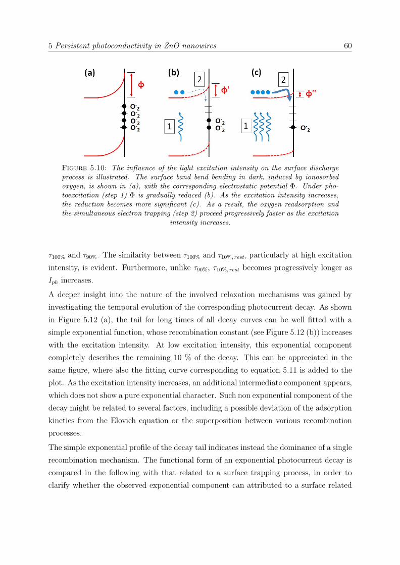
5 Persistent photoconductivity in ZnO nanowires 60
Figure 5.10: The influence of the light excitation intensity on the surface dischargeprocess is illustrated. The surface band bend bending in dark, induced by ionosorbedoxygen, is shown in (a), with the corresponding electrostatic potential Φ. Under pho-toexcitation (step 1) Φ is gradually reduced (b). As the excitation intensity increases,the reduction becomes more significant (c). As a result, the oxygen readsorption andthe simultaneous electron trapping (step 2) proceed progressively faster as the excitation
intensity increases.
τ100% and τ90%. The similarity between τ100% and τ10%, rest, particularly at high excitation
intensity, is evident. Furthermore, unlike τ90%, τ10%, rest becomes progressively longer as
Iph increases.
A deeper insight into the nature of the involved relaxation mechanisms was gained by
investigating the temporal evolution of the corresponding photocurrent decay. As shown
in Figure 5.12 (a), the tail for long times of all decay curves can be well fitted with a
simple exponential function, whose recombination constant (see Figure 5.12 (b)) increases
with the excitation intensity. At low excitation intensity, this exponential component
completely describes the remaining 10 % of the decay. This can be appreciated in the
same figure, where also the fitting curve corresponding to equation 5.11 is added to the
plot. As the excitation intensity increases, an additional intermediate component appears,
which does not show a pure exponential character. Such non exponential component of the
decay might be related to several factors, including a possible deviation of the adsorption
kinetics from the Elovich equation or the superposition between various recombination
processes.
The simple exponential profile of the decay tail indicates instead the dominance of a single
recombination mechanism. The functional form of an exponential photocurrent decay is
compared in the following with that related to a surface trapping process, in order to
clarify whether the observed exponential component can attributed to a surface related

5 Persistent photoconductivity in ZnO nanowires 61
Figure 5.11: The full recovery time τ100% is compared with the time required to ob-serve 90 % of the photocurrent decay (τ90%) and that to observe the remaining 10 %
(τ10%, rest). The similarity between the former and the latter is clearly appreciable.
process. The rate of a pure exponential photocurrent decay is simply proportional to the
density of electrons in conduction band:
(dncbdt
)exp ∝ −ncb. (5.16)
On the other hand, the rate of a surface trapping process can be written including the
corresponding Boltzmann factor, as well as its dependence on the density of non occupied
surface states available for the trapping process, Ns,0 [239]:
(dntrdt
)trap ∝ Ns,0 · exp(−φ
kT). (5.17)
Assuming that non occupied surface states are formed during light excitation as a result
of the hole-induced surface discharge, their density is proportional to the density of pho-
togenerated electrons in the conduction band ncb: Ns,0 = b ·ncb. The constant b, which is
comprised between 0 and 1, represents the efficiency of the discharge process. Therefore,
equation 5.17 can be rewritten as:
(dntrdt
)trap ∝ ncb · exp(−φ
kT). (5.18)
Assuming that the decay is entirely caused by the surface trapping process, ncb = nph−ntr,and, correspondingly:

5 Persistent photoconductivity in ZnO nanowires 62
Figure 5.12: Exponential fitting of the photocurrent decay tail after light excitation atvarious excitation intensity (a). The corresponding recombination time, shown in the
underlying table (b), increases progressively with the excitation intensity.
(dncbdt
)trap = −dntrdt∝ ncb · exp(−
φ
kT). (5.19)
Finally, expressing φ as in equation 2.2 in terms of ntr:
(dncbdt
)trap ∝ −ncb · exp(−e2n2
tr2Nε0εrkT
). (5.20)
Comparing equations 5.20 and 5.16 it can be observed that both rates are proportional
to the density of electrons in conduction band. However, the exponential one lacks the
dependence on the surface barrier, or in other terms, on the density of trapped electrons
at the surface, which progressively increases as the decay proceeds and represents conse-
quently a self-limitation factor for further electron trapping. This consideration indicates

5 Persistent photoconductivity in ZnO nanowires 63
that the observed exponential component of the photocurrent decay is caused by a dif-
ferent mechanisms, rather than by a pure electron trapping at surface states. As such,
previous studies [235, 240, 241], which attributed the observed exponential photocurrent
decay to the surface trapping process, should be considered suspiciously.
More in general, also trapping of photogenerated electrons at defect states located in
the surface depletion region can be ruled out as a possible relaxation mechanism. The
occupation probability of such trap levels and consequently their trapping rate critically
depend on their position in respect to the Fermi level, which is affected by the profile of
the surface band bending [217]. Since the latter enlarges during the photocurrent decay,
due to the progressive decrease of the electron density (see equation 2.1), the trap levels
are progressively shifted up in respect to the Fermi level and their occupation probability
consequently decreases. Similarly to what previously described in case of adsorption-
assisted electron trapping, this represents a self-limitation factor for the recombination
of charge carriers in the surface depletion region. As such, the rate of such relaxation
process cannot be simply proportional to the density of electrons in conduction band, as
in case of a simple exponential function.
Therefore, the exponential tail of the photocurrent decay seems to be prevalently related
to the slow recombination of charge carriers in the core of the nanowire. As introduced in
section 2.5, the prolonged lifetime of electrons in the conduction band can be caused in
principle by two main distinct mechanisms, namely the trapping of electrons in metastable
excited states of oxygen vacancies or the trapping of holes at localized levels in the band
gap. However, the former process would require the photoexcitation of oxygen vacancies,
which does not occur as suggested by the absence of photoresponse under below band
gap excitation. The contribution of such highly conductive metastable electron states to
the PPC can be thus ruled out. Consequently, the exponential component of the PPC is
most probably caused by the reduced electron - hole recombination probability, induced
by the hole trapping at bulk defect states.
The measurements performed do not allow to univocally determine the specific nature
of these trap levels, which could be in principle revealed by a detailed investigation of
the active electron - hole recombination paths. Among the radiative ones, the most
commonly observed in as grown ZnO include the direct recombination of electrons from
the conduction band with trapped holes at such defect levels [242] or the recombination
following the thermal release of trapped holes into the valence band [243]. The rate of
the latter recombination mechanism, in particular, is expected to increase with the tem-
perature, since the de-trapping process is typically activated by phonons. It might be

5 Persistent photoconductivity in ZnO nanowires 64
thus effectively involved in the exponential component of the photocurrent relaxation,
since a significant reduction of the PPC has been observed in several semiconductors for
decreasing temperature [150, 236, 239, 244]. However, in most of the previous studies the
experimental decay curves were simply fitted with a phenomenological strechted exponen-
tial function, in which the superposition of several recombination processes is described
by a single constant parameter. Consequently, such analysis procedure does not allow to
independently evaluate the influence of the temperature on distinct recombination mech-
anisms. Therefore, previous results cannot be conclusively compared with that presented
in this section and further photoconductivity measurements as a function of the temper-
ature would be highly beneficial for a deeper insight on bulk processes responsible for the
appearence of the PPC in ZnO nanowires.
In view of the discussed results, some conclusive comments can be done. Firsty, the
results presented in this section indicate that, within the investigated excitation intensity
range, only the minority of the photogenerated holes get trapped at bulk states, while the
majority migrate to the surface and contribute to the desorption of ionosorbed oxygen.
These results are consistent with previous time resolved photoluminescence studies, which
revealed the higher hole trapping efficiency of surface states compared to other trap levels
[245]. However, this conclusion might be not true in case of significantly higher excitation
intensity. Indeed, under the highest excitation intensity considered (5 mW/cm2), the
generated photocurrent amounts to Iph ≈ 1 µA. This corresponds to a hole density of
nh = Iph/SeµE ≈ 1017 cm−3, which per nanowire volume (≈ 10−13 cm3) amounts to
≈ 104. Such value is comparable to the expected density of adsorbed oxygen per nanowire
surface under equilibrium conditions: Sads,NW = Sads ·ANW ≈ 104 - 105 (see section 2.2.2)
and is therefore close to the maximum density of holes, which can be entirely involved in
the surface discharge process. If the excitation intensity exceeds few tens of mW/cm2, it is
thus expected that an increasing fraction of photogenerated holes can be trapped through
other mechanisms, in particular involving bulk trap levels. This may have obviously a
dramatic influence on the dynamics of the charge carrier recombination, which should be
carefully considered in view of photodection applications with ZnO nanowires.
Secondly, the common perception, according to which the appearence of the PPC in ZnO
nanowires is primarily caused by the slow re-adsoprtion of oxygen at the surface, should
be partially changed. Indeed, although it involves the majoity of photogenerated electrons
(at least 90 %), the adsorption-assisted surface trapping proceeds relatively fast compared
to other bulk trapping processes, which dominate the slow tail of the photocurrent decay.
Within this perspective, the decay of the photocurrent can be effectively described in

5 Persistent photoconductivity in ZnO nanowires 65
terms of fast and slow components, as suggested in few previous studies but without any
specific identification of the involved mechanisms [235, 246]. The obtained results reveal
correspondingly the inadequacy of more commonly adopted analysis approaches, which
are typically based on the modelling of the photocurrent decay with simple or stretched
exponential functions.
The proposed approach, based on the comparison between the dynamics of the pho-
tocurrent decay and the kinetics of the oxygen adospriton, can be extended also to other
structures based on ZnO and more generally to other semicondutors, such as various metal
oxides and GaN, whose photoconductivity properties strongly depend on the surrounding
environment [247–249].
5.3 Conclusions
In this chapter the above band gap photoconductivtiy properties of contated ZnO nanowi-
res have been investigated, focusing in particular on their dependence on the atmosphere
conditions. For this purpose, photoconductivity measurements under UV excitation were
performed in vacuum, inert amospheres and air.
High photoresponse has been observed in all considered conditions, with responsivity up
106 AW
in vacuum and slighly lower in other atmospheres. The photoconduction process has
been attributed to the discharge of the surface, as a result of iosorbed oxygen desoprtion.
The decay of the photocurrent shows a strong dependence on the surrounding environ-
ment, being particularly slow in vacuum and inert atmospheres. The charge carrier
relaxation proceeds instead faster in air, due to the readsorbtion of oxygen molecules and
the simultaneuos trapping of electrons at the surface.
This process has been quantitatively evaluated by comparing the temporal evolution of
the decay with the kinetics of the oxygen adsorption. The latter has been described
assuming that the adsorption rate follows the Elovich equation. The analysis revealed
that, in the investigated light excitation range, approximately 90 % of charge carriers
recombine through the adsorption-assisted surface trapping within few tens of seconds.
The rest of the photocurrent decay proceeds instead much slower, in the order of hundreds
or thousands of seconds, and is caused by different recombination mechanisms, which
include in particular hole trapping in the nanowire volume.

Chapter 6
Activation of Al dopants in ZnO
nanowires
This chapter reports on argon and aluminum implantation in ZnO nanowires, focusing in
particular on the thermal stability as well as on the electrical, optical and photoconduc-
tivity properties of the implanted nanowires. The photoluminescence measurements were
performed in collaboration with Robert Roder, while the electrical characterization were
conducted in collaboration with Michelle Geelen within the scope of her Master thesis
[250]. The implantation of the nanowires were carried out with the support of Andreas
Johannes.
6.1 Introduction
Enhancement of the n-type conductivity of ZnO nanowires by doping is essential in view
of various applications, especially in transparent and flexible eletronics [251] and, in con-
junction with eventual future achievements in p-type doping, for the development of ZnO
NW based LEDs and laser diodes. In particular, it has been claimed that the use of ZnO
nanowires as a buiding component in transparent transistors [252] as well as in conduc-
tive window layers and anti-reflection coatings in solar cells [253, 254] may present several
advantages over the corresponding technology based on thin films, including for instance
higher flexibility, lower reflectivity and more efficient fabrication procedures [253]. Addi-
tional successful applications of n-type doped ZnO nanowires include the development of
gas sensors [255, 256], novel photoswitches [257] and memory devices [258].
Among possible donor impurities in ZnO (see section also 2.1.4), aluminiun is one of
the most commonly used because of its large availability, low cost and non toxicity.
66

6 Activation of Al dopants in ZnO nanowires 67
Aluminum doping of ZnO nanowires during growth has been successfully performed by
means of several methodes, including thermal evaporation [259], low temperature solution
synthesis [128, 260], sol-gel spin-coating technique [261], and chemical vapor deposition
[262].
On the other hand, the literature about attempts to dope ZnO nanowires with aluminum
by post-growth ion beam implantation is rare, leaving this issue substantially unexplored.
As introduced in section 2.1.4, ion beam implantation offers various advantages over other
doping techiques, including in particular the possibility to introduce the desired impurities
in the semiconductor crystal beyond their solubility limit and to achieve a homogeneous
doping profile. As a drawback, a large density of defects may be generated during the
implantation process, which can dramatically alter and deteriorate the electrical and
optical properties of the implanted semiconductor. As such, post-implantation thermal
treatments are typically performed, in order to recover the original crystal structure and to
activate the implanted ions. However, this is a critical issue in case of contacted nanowires,
since at the high temperatures typically required for this purpose, effects such as alloying
near the contact regions [212], formation of new interface states [263] and eventually
sample degradation [220, 264, 265] may occur. Therefore, a detailed investigation of the
thermal stability properties of aluminum implanted contacted ZnO nanowires is highly
required, in order to optimize the annealing conditions and more in general the entire
doping procedure. This would be greatly beneficial for a more intense exploitation of the
ion implantation technique for the doping of contacted ZnO nanowires.
Particularly important is also the analysis of the electrical properties of the implanted
nanowires in dark as well as under illumination conditions. First of all, since some of the
generated intrinsic defects may act as shallow donors (see also section 2.1.1), it is crucial
to distinguish their contribution to the conductivity from that which can be attributed
to the implanted aluminum atoms. For this reason, it is fundamental to investigate the
electrical properties of argon implanted ZnO nanowires, in which the only expected effect
of the implantation process is the generation of defects in the nanowire. Secondly, a
deep understanding of the photoconduction process in the implanted nanowires is highly
desirable, since the introduced impurities and the generated defects in the host crystal
may drastically affect the photoresponse of ZnO, as well as the dynamics of the photo-
conductivity decay after light excitation. Specifically, the aluminum-related and intrinsic
levels may be photoactive or act as trap centers for charge carriers, affecting consequently
the electron-hole recombination rate. Additionally, change in the donor density deter-
mines a modification of the surface band bending, since the latter depends directly on the

6 Activation of Al dopants in ZnO nanowires 68
charge carrier density (see equation 2.1). As such, aluminum doping may drastically affect
surface-related processes such as the electron-hole separation and the adsorption-assisted
trapping at the surface of photogenerated electrons, which were described in Chapter 5
and play a fundamental role in the photoconduction process in ZnO nanowires.
6.2 Implantation procedure
The aluminum implantations were performed on contacted ZnO nanowires (see also sec-
tion 3.2) with diameter between 300 nm and 400 nm at the IFK/Jena using the implanter
ROMEO (see also section 3.5). The distribution of the implanted ions in the crystal
was simulated prior the implantation procedure using the Monte Carlo package SRIM
[206, 207]. According to the simulation results, ion energy of 100 keV and fluence of
1.25 · 1014 cm−2 were selected as the optimal implantation parameters, in order to obtain
an aluminum concentration maximum of around 1019 cm−3 at a depth of 100 nm.
Additionally, similar samples were implanted with argon, in order to separately investigate
the influence of the generated intrinsic defects on the optical and electrical properties of
contacted ZnO nanowires. The implantations were performed with an ion energy of 160
keV and a fluence of 1.1 · 1014 cm−2, in order to obtain a comparable ion range profile as
in the aluminum implanted nanowires.
According to the SRIM simulations, the density of defects, which were generated at the
interface between the nanowires and the SiO2 interface, as well as near the contact regions,
is substantially negligible.
6.3 Thermal stability of implanted ZnO nanowire de-
vices
At the investigated ion energies and fluences only formation of point defects is expected
in ZnO nanowires, while amorphization does not likely occur [266–268]. This is due to
the high resistence of ZnO to the ion-beam damaging and the occurrence of pronounced
dynamic annealing effects during implantation, which are typically observed in highly
ionic semiconductors and determine the immediate disappearence of a large fraction of
defects [269–272]. Nevertheless, the significant formation of defects during argon im-
plantation is proved by the drastic reduction of the dark conductivity in the implanted
sample immediately after implantation (Figure 6.1 (a)). The I-V characteristics of sam-

6 Activation of Al dopants in ZnO nanowires 69
Figure 6.1: I-V characteristics of contacted ZnO nanowires before and after argon (a)and aluminum implantation (b) and following post-implantation annealing treatments.Argon implanted nanowires are seriously deteriored by the implantation process, whileincrease in the conductivity is observed after aluminum implantation. The I-V chara-teristics of a non implanted sample, which is used as a reference for the annealing
procedures, are presented in (c).
ple before and immediately after aluminum implantation are instead substantially similar
(Figure 6.1 (b)), probably due to the lower concentration of generated defects or to the
counteracting effect of the incorporated aluminum ions, which may act as shallow donors
even immediately after implantation. Annealing procedures were then performed, in or-
der to drastically reduce the concentration of generated defects. In general, the optimal
temperature of a post-implantation annealing treatment strongly depends on the defect
formation process, which is typically affected by the nature of the target material as well
as on the mass and the chemical nature of the implanted ions. For instance, in uncon-
tacted ZnO nanowires implanted with transition metals or rare earths the original crystal
structure is recovered after annealing treatments in the temperature range between 700C and 900 C [204, 273], while a lower temperature (500 C) is required after argon

6 Activation of Al dopants in ZnO nanowires 70
implantation [274]. However, it has been shown that annealing performed in air at tem-
perature higher than 350 C with contacted ZnO nanowires leads to a complete sample
degradation [220], which can be mainly attributed to the large modification of the contact
properties due to the occurrence of allowing effects of the ZnO nanowires with Ti and
Au.
Thus, argon and aluminum implanted ZnO nanwoires were annealed at 300 C. Various
annealing durations were considered, in order to investigate the thermal stability of the
device with the implanted nanowires and to optimize the conditions of the thermal treat-
ment. Additionally, a pristine non-implanted sample was repeatedly annealed under the
same conditions and used as a reference, in order to distinghish the modifications induced
by the implantation process from that eventually related to the annealing procedure.
As shown in Figure 6.1 (b), a thermal treatment for 30 min does not induce any ap-
preciable change in the I-V characteristics of the aluminum implanted sample, while a
substantial increase of the dark conductivity, by more than one order of magnitude, is
observed after 4 hours annealing. A further thermal treatment for 8 hours leads only
to a slight improvment of the I-V characteristics, indicating the eventual saturation of
the conductivity increase. Since the thermal treatments were performed at relatively
low temperature, it is unlikely that the original crystal structure of the nanowires is com-
pletely recovered. This assumption is also corroborated by the investigation of the optical
properties of the implanted nanowires, which will be discussed in the next section. It is
therefore likely that the observed saturation of the conductivity increase is caused by the
occurrence of the previously mentioned thermally-induced degradation effects.
On the other hand, the device conductivity is drastically reduced in the argon implanted
sample immediately after implantation and is not recovered after analogous annealing
procedures (Figure 6.1 (a)). Deterioration of the I-V characteristics is also observed in
the annealed reference sample (Figure 6.1 (c)). As such, the observed increase of the
conductivity in aluminum implanted ZnO nanowires can be entirely attributed to the
partial recovery of the crystallinity and simultaneous ionization of the aluminum donors,
without significant contribution from intrinsic defects.
SEM pictures taken after implantation and following annealing treatments reveal that the
implantation process does not induce apprecciable surface roughness, although a slight
reduction of the nanowire diameter can be observed after argon implantation (Figure
6.2). This can be attributed to the occurrence of sputtering effects, which are induced by
the implanted argon ions [275].

6 Activation of Al dopants in ZnO nanowires 71
Figure 6.2: SEM pictures of contacted ZnO nanowires after argon and aluminumimplantation and following post-implantation annealing treatments. Both implantationprocesses do not induce apprecciable surface roughness. Only a slight reduction of the
nanowire diameter can be observed after argon implantation.
6.4 Optical properties of implanted ZnO nanowires
The impact of the aluminum and argon implantation on the optical properties of the
contacted ZnO nanowires was investigated by means of micro-photoluminescence spec-
troscopy. The measurements were performed at 4 K after the longest post-implantation
annealing (8 hours), using a He-Cd laser as excitation light source at 325 nm.
The complete spectra of the implanted samples are shown in Figure 6.3. As a reference,
the spectra of an untreated contacted nanowire is added to the graph. All spectra are
characterized by two distinct emission bands, namely the near band edge emission (NBE)
and the deep level emission (DLE) of ZnO, which are located respectively in the UV and
in the visible spectral range. The photoluminescence intensity is normalized in respect
to the NBE.

6 Activation of Al dopants in ZnO nanowires 72
Figure 6.3: Photoluminescence spectra of contacted ZnO nanowires before and afterargon and aluminum implantation. The samples underwent various post-implantationannealing treatments at 300 C, with maximum duration of 8 hours. The spectrum ofa pristine sample is also presented. The spectra are characterized by a near band edgeemission in the UV spectral range and a broad emission band in the visible range, whichis caused by various recombinations at deep levels. The band centered around 2.8 eV is
an artifact of the PL seput.
The DLE of the pristine sample is dominated by the green luminescence, which has the
maximum intensity at around 2.4 eV. This emission originates from the recombination at
defect levels located in the bulk as well as at the nanowire surface, including in particular
oxygen and zinc vacancies [276–279]. The NBE results instead from the overlap of various
excitonic emissions, which will be described in more detail in the following paragraph.
In comparison to the pristine sample, the NBE of the implanted nanowires is much
broader and the ratio with the DLE decreases, indicating that the performed annealing
procedures do not completely recover the original crystal structure of the nanowires.
Moreover, an additional component of the DLE, which is substantially absent in the
as-grown nanowires, appears in the argon and especially in the aluminum implantend
samples at photon energies lower than 2 eV. This can be attributed to the recombination
between donor levels and oxygen interstitials [280, 281], which can be likely generated
during implantation, while are typically present in low concentration in as grown ZnO
nanowires (see also section 2.1.1). The large band centered around 2.8 eV is instead an
artifact of the PL measurement setup, which was caused by the back reflection of white
light into the monochromator.
High resolution spectra of the NBE from the same nanowires are shown in Figure 6.4
(a). The dominant emission peak is centered approximately at 3.36 eV in all investigated

6 Activation of Al dopants in ZnO nanowires 73
Figure 6.4: High resolution photoluminescence spectra of the near band edge emission(NBE) of contacted ZnO nanowires before and after argon and aluminum implantation(a). The spectrum of a pristine sample is also presented. A close up of the NBEmaximum in (b) shows the main emission lines, which are caused by the recombination
of bound excitons.
samples and is composed by various emission bands (I9 - I3), which are highlighted more
in detail in Figure 6.4 (b) and are related to the recombination of several neutral donor
bound excitons (D0X) [282, 283]. The NBE from the pristine sample is dominated by
the lines I6,6a and I5, which are related to aluminum acting as a shallow donor [282, 284].
This was probably incorporated as a trace during growth of the ZnO nanowires from the
Al2O3 boat and the tube of the furnace. In the pristine sample also the emission lines I9,
I8, I4 and the SX can be recognized. The former two are typically attributed to excitons
bound respectively to indium [285] and gallium [286], which are present as contamination
impurities in the used ZnO powder, while I4 is related to hydrogen acting as a shallow
donor [282], which is also unintentionally incorporated during growth. The emission line
SX is instead assigned to surface bound excitons (SX) [287, 288]. The emission line I5
fully dominates the NBE emission from the aluminum implanted sample, proving thus the
optical activation of implanted aluminum atoms as shallow donors. On the other hand, it
is much weaker in the argon implanted sample. Additionally, in both implanted samples
also the line I3 can be recognized, which is related to Zn interstitials eventually generated
during implantation. The high energy shoulder of the NBE originates instead from the
free exciton recombination (FX) [289], while on the lower energy side several peaks can be
recognized. These include in particular the two-electron-satellite emission (TES) [282],
which occurs when the neutral donor is excited from the 1s ground state to an excited
state after recombination of the bound exciton [290], and the longitudinal phonon replica

6 Activation of Al dopants in ZnO nanowires 74
1LO and 2LO of the excitonic emissions [282]. Such emission lines substantially disappear
after argon and aluminum implantation, indicating once again the non complete recovery
of the crystal structure after the post-implantation annealing procedures.
6.5 Photoconductivity properties of implanted ZnO
nanowires
6.5.1 Photoresponse
The impact of the ion implantation on the photoresponse properties of contacted ZnO
nanowires was investigated by measuring the photocurrent in air under steady state ex-
citation conditions before and after implantation. The measurements were conducted
under UV illumination at 20 µW/cm2 and 5 mW/cm2, in order to explore different exci-
tation intensity regimes. Additionally, also the photoresponse properties of the reference
sample for the annealing procedures were investigated, in order to distiguish the mod-
ifications induced by the implantation process from that eventually attributable to the
post-implantation annealing procedure. In particular, thermal treatments may affect the
photoconduction process mainly due the induced change in the defect concentration, as
well as the modification of the contact and surface properties.
The measured values of the dark current (Idark) and the photocurrent (Iph) are summa-
rized in table 6.1. Immediately after argon implantation and the following annealing for
4 hours, the dark current and the photocurrent values were below the sensitivity of the
SMU and are thus not reported. The photoresponse is quantified in Figure 6.5 in terms
of the photosensitivity, which is the ratio between Iph and Idark.
Enhanced photoresponse is observed in the sample implanted with aluminum after post
implantation annealing under light excitation at 20 µW/cm2 (Figure 6.5 (a)). In partic-
ular, a progressive increase of the annealing duration leads to increasing photosensitivity.
However, this effect cannot be simply attributed to the gradual recovery of the crystal
structure, since decreasing photosensitivity is observed in the argon implanted as well as
in the reference sample after analogous annealing treatments. Although the literature
about this point is quite rare, enhancement of the photoresponse under below band gap
excitation has been observed in porous aluminium-doped zinc oxide nanofibers and at-
tributed to the photoexcitation of aluminum related shallow levels [257]. A similar effect
might thus also occur in the nanowires investigated within this work. On the other hand,
decreased photoresponse is observed in all samples under excitation at 5 mW/cm2. The

6 Activation of Al dopants in ZnO nanowires 75
Table 6.1: Values of the dark current and the photocurrent in contacted ZnOnanowires before and after argon and aluminum implantation. The corresponding valuesof a non-implanted sample, which is used as a reference for the annealing procedures,are also presented. The missing values marked as X in the argon implanted sample were
lower than the SMU sensitivity and are therefore not reported.
Sample Treatment Idark IUV (20 µW) IUV (5 mW)
Al implanted
BeforeImplantation
(0.10 ± 0.05) pA (9 ± 1) pA (46 ± 4) nA
After Implanta-tion, beforeannealing
(1.0 ± 0.3) pA (4.7 ± 0.5) pA (0.66 ± 0.08) nA
After Implanta-tion and anneal-ing (4h at 300C)
(10 ± 1) pA (1.4 ± 0.2) nA (0.32 ± 0.05) µA
After Implanta-tion and anneal-ing (8h at 300C)
(15 ± 1) pA (3.8 ± 0.5) nA (0.73 ± 0.05) µA
Ar implanted
BeforeImplantation
(1.5 ± 0.5) pA (3.0 ± 0.5) pA (13 ± 1) nA
After Implanta-tion, beforeannealing
X X X
After Implanta-tion and anneal-ing (4h at 300C)
X X X
After Implanta-tion and anneal-ing (8h at 300C)
(0.1 ± 0.05) pA X (2.2 ± 0.3) pA
Annealed reference
BeforeAnnealing
(0.3 ± 0.05) pA (85 ± 1) pA (0.33 ± 0.05) nA
After annealing(4h at 300 C)
(0.1 ± 0.05) pA (5.3 ± 0.7) pA (82 ± 1) pA
After annealing(8h at 300 C)
(0.10 ± 0.05) pA (4.7 ± 0.5) pA (8 ± 1) pA
evidence that the photosensitivity of aluminum implanted ZnO nanowires is effectively
enhanced only under excitation at low intensity, suggests that the photogeneration of
higher density of charge carriers leads most likely to enhanced scattering effects, which
cause the observed reduction of the photosensitivity.

6 Activation of Al dopants in ZnO nanowires 76
Figure 6.5: UV Photosensitivity in aluminum (a) and argon implanted ZnO nanowiresunder steady state UV excitation at 20 µW/cm2 and 5 mW/cm2. The photosensitivityis measured immediately after implantation and following post-implantation annealingtreatments. The photosensitivity is calculated as a ration between the photocurrentand the dark current, which were taken from table 6.1. The photosensitivity of a nonimplanted sample, which is used as a reference for the annealing procedures, is also
reported.
6.5.2 Persistent photoconductivity in Al doped ZnO nanowires
The dynamics of the persistent photoconductivity in aluminum implanted ZnO nanowires
was investigated by measuring the photocurrent decay after UV illumination at various
excitation intensity, ranging from 20 µW/cm2 up to 5 mW/cm2. The light excitation was
keept on for 5 s and the decay was measured until the complete recovery of the original
dark current. Similarly to the previous investigations presented in this chapter, analogous
measurements were performed using the argon implanted as well as the reference samples.
A preliminary remark concerns the optimal method to accurately compare the photocur-
rent decay times in the investigated nanowires before and after doping or annealing. In
fact, it has been shown in the previous section that such treatments drastically modify
the photoresponse properties of the nanowires, leading to significantly different values

6 Activation of Al dopants in ZnO nanowires 77
Figure 6.6: Comparison of the photocurrent decay times of not-implanted ZnOnanowires before and after annealing at 300 C for 8 hours. The decay times areplotted in (a) as a function of the excitation intensity and in (b) as a function of thecorresponding generated photocurrent. The latter graph reveals that the decay times
cannot be compared straightforwardly.
of the photocurrent values in the untreated and treated samples. This fact complicates
obviously the comparison of the photoconductivity decay in different samples, since even
in the same sample the dynamics of the decay critically depends on the value of the gen-
erated photocurrent, as detailed described in section 5.2. As such, any treatment of the
nanowires may impact the photoconductivity decay process through two distinct effects:
by direct modification of the decay mechanisms, for instance by generating or suppress-
ing charge carrier recombination channels, or indirectly by changing the photoresponse
properties. It is therefore crucial to distinguish the latter from the former contribution, in
order to avoid misleading or wrong intepretations of the experimental results. These may
occur for instance when the photocurrent decay times are compared as a function of the
excitation intensity, as shown for example in figure 6.6 (a) in case of the reference sample
before and after thermal annealing. The graph clearly suggests that the relaxation of the
photogenerated charge carriers proceeds much faster in the annealed sample. However,
the eventual difference in photoresponse of the two samples is not taken into account. In
order to circumnavigate this problem, a possible solution is to plot both decay times as a
function of the generated photocurrent. Considering the previous example, the new graph
in figure 6.6 (b) reveals instead that the comparison for this specific sample cannot be
done straightforwardly, due to poor overlap of the generated photocurrents. Extrapola-
tion of the experimental data can be therefore required, in order to meaningfully compare
the photocurrent decay in different samples.

6 Activation of Al dopants in ZnO nanowires 78
The analysis of the slow photoconductivity decay (PPC) in non-implanted ZnO nanowires,
which was conducted in chapter 5, revealed that the decay process can be described in
terms of two distinct components. The initial part of decay involves around 90 % of the
photogenerated charge carriers and is caused by a pure surface effect, which consists in
the adsorption-assisted trapping of electrons at the surface. The rest of the photocurrent
decay is instead induced by different recombination mechanisms, which include in par-
ticular the trapping of holes at various bulk defect states. It is therefore reasonable to
investigate the relaxation of photogenerated charge carriers in aluminum implantend ZnO
nanowires, by individually analysing the mentioned components of the decay, in order to
precisely evaluate the impact of the implantation on the corresponding recombination
mechanisms.
The decay time related to the first component (τ90%) in the aluminum implanted sample
is compared in figure 6.7 (a) with that measured before implantation as a function of
the generated photocurrent. For both sets of data, increasing values of the photocurrent
correspond to increasing excitation power. To be rigorous, the decay times corresponding
to the same excitation intensity cannot be individually compared, as the corresponding
values of the photocurrent slighly differ. Nevertheless, since the ranges spanned by the
generated photocurrent before and after implantation overlap for more than 2 orders of
magnitude, it can be in general concluded that the the photoconductivity decay after
implantation proceeds significantly slower than before. Similarly, also the remaining 10
% of photogenerated charge carriers recombine slower after aluminum implantation, as
shown in figure 6.7 (b).
On the other hand, the thermal annealing alone does not affect substantially the dynamics
of the photocurrent decay, as can be seen in figures 6.7 (c) and (d). Only at low excitation
intensity a slight increase of τ90% by less than a factor of 2 is observed (figure 6.7 (d)),
which is anyway negligible in comparison to the corresponding increase by few orders
of magnitude observed in the aluminum implanted sample. In both graphs 6.7 (c) and
6.7 (d) the originally poor overlap of the photocurrent ranges was improved by adding
experimetal data, which were obtained from a similar pristine sample under the same
excitation conditions. No data from the argon implanted nanowires are instead reported,
as the generated photocurrent was lower than the sensitivity as the SMU.
The performed analysis suggests thus that the drastic modification of the photoconductiv-
ity decay properties in aluminum implanted ZnO nanowires can be completely ascribed to
the implantation process and not to the following post-implantation annealing treatment.
The observed enhancement of the persistent photoconductivity indicates a prolongation

6 Activation of Al dopants in ZnO nanowires 79
Figure 6.7: Photocurrent decay times in contacted ZnO nanowires before and afteraluminum implantation and following thermal annealing. The decay times correspond-ing to the initial 90 % of the decay are plotted in (a), while that related to the remaining10 % are presented in (b). The analogous decay times in the sample used as a referencefor the annealing procedure are shown respectively in (c) and (d). The experimental
data connected by the dashed lines were obtained with a similar pristine sample.
of the electron lifetime in conduction band with a corresponding reduction of the charge
carrier recombination rate. In particular, the slowing down of the adsorption-assisted
electron trapping may be caused by the enlargement of the surface depletion region (see
also chapter 5) or the increase of the surface potential barrier, which hinder the pene-
tration of electrons toward the trapping sites at the surface. Both the depletion region
width and the surface barrier height depends explicitly on the electron density and on
the density of occupid surface states (see equations 2.1 and 2.2). The increase of the
electron density causes a reduction of both the depletion region width and the surface
barrier height, while the increase of the density of occupied surface states determines their
enlargement. As such, the enhancement of the n-type conductivity in ZnO by Al dop-
ing should in principle favor a faster electron trapping and a consequent reduction of the

6 Activation of Al dopants in ZnO nanowires 80
PPC. However, the observed reduction of the electron trapping rate at the surface after Al
implantation reveals a significant increase in the density of occupied surface states, which
seems to dominate on the former counteracting effect. A possible explanation is based on
the fact that the implantation process likely generates further surface states by sputter-
ing [269, 275], which may cause the increase of the surface barrier height. Moreover, the
generation of defect states may be also responsible for the slower charge carrier relaxation
in the volume of the nanowire after implantation. The photoluminescence measurements
presented in section 6.4 revealed the increased density of defect levels, which are involved
in the DLE in ZnO nanowires. In particular, oxygen interstitial, which are responsible for
the appearence of the red luminescence in the aluminum implanted sample, are known
to act as hole trap centers [291]. As such, an enhancement of the hole trapping in the
volume of the nanowire is likely to occur in aluminum implanted nanowires, leading to a
reduction of the electron-hole recombination probability and to the observed prolongation
of the photocurrent decay time.
6.6 Conclusions
In this chapter the thermal stability as well as the optical and above band-gap photo-
conductivity properties of argon and aluminum implanted ZnO nanowire devices have
been investigated. Post-implantation annealing procedures were conducted, in order to
reduce the density of point defects, which were generated during implantation. Despite
the non complete recovery of the original crystal structure, electrical and optical char-
acterizations revealed the successful activation of the aluminum ions as shallow donors
in ZnO after thermal annealing at 300 C for 8 hours. Steady state photoconductivity
measurements were performed, in order to investigate the photoresponse properties in the
implanted nanowires. Enhancement of the UV photosensivity after aluminum implanta-
tion has been observed at low excitation intensity and attributed to the photoexcitation
of aluminum-related states. On the other hand, significant deterioration of the photore-
sponse properties has been observed in argon implanted nanowires, as well as in the
non-implanted sample, which was used as a reference for the annealing procedure.
The dynamics of the photoconductivity decay has been investigated as a function of the
excitation intensity, revealing a significant enhancement of the persistent photoconduc-
tivtiy in the aluminum implanted nanowires. The reduced rate of the adsorption-assisted
electron trapping at the surface, which is responsible for the decay of 90 % of the pho-
tocurrent in non implanted ZnO nanowires, is attributed to the possible increase of the

6 Activation of Al dopants in ZnO nanowires 81
surface barrier height after implantation. Such effect is most likely caused by the gen-
eration of further surface states during implantation. Furthermore, the generation of
defects in the volume of the nanowire has a strong impact on other bulk-related recombi-
nation channels. In particular, the increased concentration of oxygen interstitials, which
is revealed by the photoluminescence measurements, leads to enhanced hole trapping pro-
cesses. This determines a reduction of the electron-hole recombination probability and
the observed enhancement of the persistent photoconductivity.

Chapter 7
Hydrogen sensing with ZnO
nanowires
This chapter deals with the room temperature hydrogen sensing properties of contacted
ZnO nanowires. The gas sensing mechanism in the pristine devices is investigated by
comparing the dynamics of the device conductivity change upon interaction with hydro-
gen molecules and UV excitation. A corresponding model for the H2/ZnO interaction
is proposed. Plasma treatments in argon and oxygen atmospheres as well as thermal
annealing procedures under oxygen flow are investigated as possible methods for the en-
hancement of the gas sensitivity. The sensing measurements on the argon plasma-treated
devices were conducted in collaboration with Maximilian Zapf within the scope of his
Bachelor thesis [292]. Ronny Nawrodt and Christian Schwarz assisted in performing the
plasma treatments.
7.1 Motivation
The strong influence of the surrounding environment on the electrical properties of ZnO
nanowires, which was investigated in chapter 5, makes such nanostructures excellent can-
didates for the develompment of a novel generation of miniaturized gas sensors with
enhanced performances. The enhanced surface to volume ratio as well as the easy to
specifically functionalize or modify the surface properties [293], are among the most re-
markable features of ZnO nanowire based gas sensors. Further advantages of using ZnO
nanowires for gas sensing applications as alternative to the correponding thin film tech-
nology include their superior stability [294], possible large-scale production [295] and
considerable reduction in terms of power consumption [110, 111].
82

7 Hydrogen sensing with ZnO nanowires 83
The pronounced sensitivity of ZnO nanowires toward a large variety of gas molecules
has been proved by an exponentially growing number of publications during the last
decade (see for example [35, 296–298]). In particular, there is increasing interest in the
development of hydrogen gas sensors based on ZnO nanowires. Hydrogen is the most
abundant element in nature and finds application in several industrial processes, such as
oil and metal refining, food processing and electronics manufacturing [299]. Furthermore,
it is considered as a potential source of clean energy [300]. However, hydrogen has a
wide concentration window of flammability and, due to its extremely reduced weight, the
greatest tendecy to leak among atomic and molecular species [301]. Therefore, the devel-
opment of suitable and efficient hydrogen sensors is fundamental for the implementation
of appropriate safety procedures.
Several types of hydrogen sensors based on ZnO nanowires have been demostrated, in-
cluding in particular ZnO nanowire arrays and networks [302] and single nanowire devices
[35, 140, 296]. Surface functionalization with noble metal nanoparticles is often consid-
ered, in order to enhance both gas sensitivity and selectivity [297, 303]. However, drastic
lowering of the operation temperatures is highly desirable, since most of the gas sen-
sors operate typically at few hundreds degrees Celsius [304], at which hydrogen may
potentially become explosive [305]. Furthermore, the use of metallic nanoparticles as
a functionalizing elements may be eventually deleterious for the electrical properties of
ZnO nanowires, since it is known that metallic coatings on ZnO induce the formation of
mid-gap states in the proximity of the surface, which can act as trap centers for charge
carriers [92, 93]. Novel strategies must be therefore developed, in order to find alternative
methods for enhancing the room temperature hydrogen sensitivity of ZnO nanowires.
Secondly, despite the extensive activity in reseach and development of such gas sensors,
the understanding of the sensing mechanism is still quite poor [185]. Although it is typ-
ically believed that the detection occurs as a result of the interaction between hydrogen
molecules in gas phase and adsorbed oxygen species on the ZnO surface [185], a con-
vincing evidence for the occurrence of this process is still missing. This is mainly due to
the lack of experimental techniques able to probe the dynamics of the detection process
and to the fact that most of the computational studies do not include in the simulations
the presence of adsorbed species on the nanowire surface. Additionally, even assuming
that the hydrogen molecules interact effectively with the adsorbed oxygen species, it is
also not know whether the hydrogen leave the surface after the interaction or gets irre-
versibly adsorbed. Furthermore, the occurrence of different detection mechanisms cannot
be completely excluded. For instance, it is in principle possible that under dissociation

7 Hydrogen sensing with ZnO nanowires 84
of the hydrogen molecules at the surface, the atomic hydrogen components diffuse into
the nanowire and act as a shallow donors, causing the increase of the sensor conductivity.
This could occur in particular on reduced ZnO surfaces or after functionalization with
noble metal nanoparticles, since in both conditions the molecular dissociation is favored
[34, 107, 306].
Further investigations about the interaction mechanism between hydrogen molecules and
ZnO nanowires are therefore highly required. Deeper understanding about the hydrogen
detection mechanism is fundamental for the enhancement of several sensor parameters,
such as sensitivity, selectivety as well as response and recovery speed. Furthermore, the
development of an accurate model for the hydrogen sensing mechanism in ZnO nanowires
could represent the basis for more sophisticated models describing the detection of more
complex molecules.
7.2 Hydrogen sensing properties of untreated ZnO
nanowire devices
Hydrogen sensing measurements with contacted ZnO nanowires were performed by mea-
suring the change of the electrical conductivity in single ZnO nanowire devices upon
interaction with hydrogen molecules. The measurements were performed at a pressure
of 1 atm in a reference atmosphere of nitrogen flowing at 1000 sccm, by letting into the
measuring chamber hydrogen from a formier gas supply at various flow values between 10
and 1000 sccm. Further details concerning the measurement setup and the experimen-
tal procedures, including the method for the calculation of the hydrogen sensitivity, are
described in section 3.3.3.
As shown in Figure 7.1 (b), the conductivity of the devices increases as soon as hydrogen
molecules are introduced in the chamber. After stopping the hydrogen flow, the con-
ductivity starts to decay slowly. As soon as air is added to the nitrogen atmosphere,
the decay speeds up significantly, until the current reaches the original reference value.
The dependence of the gas sensitivity (see section 3.3.3) on the hydrogen concentration
is presented in Figure 7.1 (a). The nanowires do not show any sensitivity toward hydro-
gen concentration lower than 500 ppm, which represents the threshold for a measurable
change in the nanowire conductivity. Higher hydrogen concentration leads to an increase
of the gas sensitivitiy, which tends progressively to saturate.

7 Hydrogen sensing with ZnO nanowires 85
Figure 7.1: Change of the conductivity in contacted ZnO nanowires when hydrogenflow is introduced in a reference nitrogen atmosphere (a). The conductivity decaysslowly after stopping the hydrogen flow. Faster decay rate is observed as soon as air isintroduced into the measuring chamber. The dependence of the gas sensitivity on the
hydrogen concentration is shown in (b).
The obtained results indicate that an electron transfer occurs from the hydrogen molecules
into the conduction band of the nanowires. After stopping the hydrogen flow, the trans-
ferred electrons relax, as suggested by the observed decay of the condutivity. The conduc-
tivity decay is characterized by a remarkable dependence on the atmosphere conditions,
being slow in the inert nitrogen atmosphere and faster in air. This behaviour resem-
bles that already observed in similar samples after UV excitation, which was detailed
investigated in section 5.1. This evidence suggests that the respective electron relaxation
mechanism might be similar.
In order to corroborate this hyphotesis, the electron relaxation processes after hydrogen
detection and UV excitation will be quantitatively compared in the following. For this
purpose, a new sensing measurement was performed in a reference atmosphere containing
air. Hydrogen flow was let into the chamber in concentration of 4000 ppm and kept on
until saturation of the current. Air was considered as a reference atmosphere instead
of nitrogen in order to speed up the recovery of the reference current after stopping
the hydrogen flow. The photoconductivity measurement was carrier out in air under
UV excitation intensity of 20 µW/cm2. The UV excitation was kept on for the time
sufficient to induce the same change of the current, which was observed upon interaction
with hydrogen molecules. Under these conditions, the respective decay processes can be
directly compared.
Both current decays are shown in figure 7.2, immediately after stopping respectively the

7 Hydrogen sensing with ZnO nanowires 86
UV illumination and the hydrogen flow at t = 0 s. In both plots the reference and the
dark currents have been subtracted. It can be observed that the decay rates are sub-
stantially equal until the current decays by 90 % of its maximum value. In chapter 5 it
was proved that the UV illumination induces the desorption of oxygen species, which are
typically adsorbed on the ZnO surface in equilibrium conditions. After light excitation,
oxygen molecules tends to readsorb from the surrounding environment, trapping simul-
taneously photogenerated electrons and causing around 90 % of the photocurrent decay.
The experimental evidence that this fraction of the current decay proceeds at the same
rate after UV excitation as well as after hydrogen flow, suggests that also the majority
of the electrons, which are transferred from the hydrogen molecules into the conduction
band of the nanowire, relax after detection through the same adsorption-assisted trapping
mechanism. This fundamental conclusion can be further exploited, in order to gain deeper
insight about the interaction mechanism between hydrogen molecules and the nanowire
surface. In fact, it has been observed that after stopping the hydrogen flow, the decay of
the current in air proceeds until the original value of the reference current is recovered
(Figure 7.1). This indicates that the density of oxygen adsorbed species at the end of
the decay process and before introducing hydrogen in the chamber must be the same. In
other terms, oxygen molecules tend to readsorb after stopping the hydrogen flow, in order
to recover the coverage density of equilibrium conditions. Therefore, a reduction of the
density of adsorbed oxygen species must occur during the interaction between hydrogen
molecules and the nanowire surface. In the light of this conclusion, two possible alterna-
tive mechanisms for the interaction between hydrogen molecules and ZnO nanowires can
be discussed:
1. hydrogen molecules simply remove adsorbed oxygen species from the adsorption
sites and get there adsorbed (Figure 7.3 (a));
2. hydrogen molecules interact with adsorbed oxygen species, eventually forming water
molecules, which desorb from the surface of the nanowire and leave unoccupied
adsorption sites (Figure 7.3 (b)).
The former process has been proposed to occur in case of ethanol sensing with ZnO
nanowires and is based on the different adsorption energies of ethanol and oxygen on
ZnO [307]. Since the adsorption energy of the former is higher than that of the latter, it
is likely that under ethanol flow the previously adsorbed oxygen molecules are removed
from the surface and substituted at the adsorption sites by ethanol molecules. However,
this process is unlikely to occur in case of hydrogen sensing, as the adsorption energy

7 Hydrogen sensing with ZnO nanowires 87
Figure 7.2: Comparison of the current decays in contacted ZnO nanowires after stop-ping respectively the hydrogen flow and UV excitation in air atmosphere. The majorpart of the charge carriers (90 %) relax in both cases at the same rate, suggesting the
occurrence of the same recombination mechanism.
of hydrogen on ZnO is lower than that of oxygen [308–310]. Additionally, the eventual
presence of nearly irreversibly adsorbed hydrogen species on the previous oxygen adsorp-
tion sites would change the dynamics of the following oxygen readsoprtion after stopping
the hydrogen flow. However, this would be in contracdition with the evidence that the
readsorption proceeds at the same rate also after UV excitation in absence of hydrogen in
the surrounding atmosphere (figure 7.2). As such, the second proposed model is probably
more realistic. The hydrogen sensing mechanism in ZnO nanowires can be therefore de-
scribed in terms of injection of previously trapped electrons into the conduction band of
ZnO, as a result of a chemical reaction between hydrogen molecules and oxygen adsorbed
species.
7.3 Argon and oxygen plasma treatments
Since the detection of hydrogen molecules with ZnO nanowires results from a chemical
reaction between hydrogen molecules in gas phase and adsorbed oxygen molecules, a
change of the density of the latter species may drastically alter the hydrogen sensitivity
of ZnO nanowire devices.
Plasma treatments are among the most effective methods for the modification of the
surface properties of semiconductors [311]. In particular, plasma treatment in oxygen
atmosphere has been proven to enhance the density of ionic oxygen related species, such as
O2−, O− and OH−, on the ZnO surface [312]. Additionally, plasma treatments at typical

7 Hydrogen sensing with ZnO nanowires 88
Figure 7.3: Alternative models for the hydrogen sensing mechanism in contacted ZnOnanowires. The injection of electrons into the conduction band of the nanowire uponinteraction with hydrogen molecules might result from the replacement of previousy ad-sorbed oxygen molecules with hydrogen molecules at the adsorption sites (a) or froma chemical reaction with the adsorbed oxygen species, which generates desorbing water
molecules (b). The latter model seems to be more realistic (see also text).
power values of several tens of Watts may generate oxygen vacancies at the surface of ZnO
nanowires as a result of the bombardment process [313, 314], since these have formation
energy of around 2.8 eV [315]. It is under debate whether oxygen vancancies may act
as preferential adsorption sites for oxygen molecules and more in general for other gas
molecules. While some theoretical studies revealed an enhancement in the gas sensitivity
[310, 316], some others [307] have shown that that the presence of oxygen vacancies on
the nanowire surface lead to a reduced interaction between the ethanol molecules and the
nanowire, leading consequently to a decrease of the gas sensitivity.
In addition to the plasma treatment in oxygen atmosphere, it is therefore interesting to
consider the effect of plasma in argon, in order to separately investigate the influence of
the ionic oxygen related species on the hydrogen sensing properties of ZnO nanowires,
from that induced by the oxygen vacancies. For this purpose, single nanowire devices
were selected and divided in two groups, which were treated either in argon or in oxygen
atmosphere.
Since the litarature about the investigation of plasma treatments on ZnO nanowires for
sensing applications is quite rare, low values of the plasma parameters were selected,
in order to avoid the occurrence of significant sample degradation effects. For both
atmospheres the gas flow and the chamber pressure were kept respectively at 50 sccm
and 0.7 mbar. The lowest values for the plasma power and the treatment duration,

7 Hydrogen sensing with ZnO nanowires 89
Figure 7.4: SEM pictures of contacted ZnO nanowires several weeks after plasmatreatments in oxygen (a) and argon atmospheres (b). The surface of the oxygen-treatednanowire is characterized only by slight roughness, while after plasma treatment inargon the roughness is more significant and a shrinking of the nanowire diameter can
be observed.
which could ensure sufficient operation stability of the plasma system, were respectively
30 W and 60 s. Scanning electron microscope pictures were taken a few weeks after the
treatments, at the end of the electrical and gas sensing measurements. Two examples
of treated nanowire devices are shown in figure 7.4. While the surface of the oxygen-
treated nanowire is characterized by only slight roughness (figure 7.4 (a)), that of the
argon-treated nanowire is significantly more rough (figure 7.4 (b)). In the latter case also
a considerable shrinking of the nanowire diameter can be observed. This indicates a more
significant occurrence of sputtering effects for the treatment in argon compared to that
in oxygen, which is due to the heavier mass of argon. As such, the plasma treatment in
argon atmosphere results more aggressive for ZnO nanowire devices.
The impact of the plasma treatments on the electrical properties of the nanowires is
presented in figures 7.5 (a) and (b). An increase of the device conductivity is observed
immediately after the treatment in argon. However, the induced change is not stable, as
the conductivity is significantly reduced one week after the treatment. On the contrary,
an initial deterioration of the I-V characteristics is observed immediately after plasma
in oxygen, while the original conductivity is recovered after one week. A previous study
about the photoluminescence properties of uncontacted ZnO nanowires [317] suggested
that hydrogen atoms are eventually incorporated during plasma treatments in a contam-
inated argon atmosphere. Therefore, the temporary increase of the device conductivtiy
observed after argon plasma can be attributed to the incoporated hydrogen atoms acting
as shallow donors [49]. The decrease of the conductivtiy after one week is caused most

7 Hydrogen sensing with ZnO nanowires 90
Figure 7.5: I-V characteristics of contacted ZnO nanowires before and after plasmatreatments in argon (a) and oxygen (b) atmospheres. Increased conductivity is observedimmediately after plasma treatment in argon, which substantially reduces after one week.The treatment in oxygen induces a temporary degradation of the I-V characteristics,
which are completely recovered after one week.
likely by the progressive diffusion of hydrogen out of the nanowire due to its high mobility
in ZnO [318]. The generation of oxygen vacancies at the surface during the treatment also
occurs, as suggested by previous studies [313, 319] and by the increased roughness of the
nanowire surface (figure 7.4). On the other hand, the temporary degradation of the I-V
characteristics after the plasma treatment in oxygen atmosphere indicates the reduction
of either the electron density or the electron mobility. Previous studies conducted on ZnO
nanowire FETs revealed a positive shift of the threshold gate voltage after oxygen plasma
[319], which clearly indicates that the reduction of the electron density is the dominant
effect. This is most probably due to the increased density of oxygen related species on
the surface of the nanowires after plasma treatment in oxygen atmosphere [312], which
capture electrons from the conduction band of ZnO. Since these species are highly reac-
tive, it is possible that they easily react with other molecules in air or leave the surface of
the nanowire, releasing progressively the captured electrons back to the conduction band.
This process may therefore lead to the observed recovery of the pristine conductivity one
week after the treatment.
The sensing measurements with the plasma-treated devices were performed under hy-
drogen concentration of 4000 ppm in a nitrogen reference atmosphere. The hydrogen
flow was kept on until the current saturates. As shown in figure 7.6, the gas sensitivity
is drastically reduced immediately after both treatments. It is substantially recovered
after one week only in the oxygen-treated devices, while it vanishes in the other samples.

7 Hydrogen sensing with ZnO nanowires 91
Figure 7.6: Influence of plasma treatments in argon (a) and oxygen (b) atmosphereson the hydrogen sensitivity of contacted ZnO nanowires. Significant reduction of thesensitivity is observed immediately after both treatments. However, the pristine sensi-
tivity is recovered in the oxygen-treated devices one week after the treatment.
These results indicate that plasma treatments in argon and oxygen atmosphere have a
deleterious impact on the hydrogen sensing properties of ZnO nanowires. The reason
of the temporarly vanishing sensitivity immediately after plasma treatment in oxygen is
not clear, as the specific interaction of the hydrogen molecules with the reactive species,
which are introduced at the surface by the treatment, may differ from that with the sim-
ply adsorbed oxygen molecules (Figure 7.3). However, the recovery of the gas sensitivity
one week after the treatment confirms that the ionic oxygen related species introduced by
the treatment on the surface of the nanowires are particularly reactive and therefore not
stable, as previously suggested by the analysis of the I-V characteristics. On the other
hand, the progressive reduction of the hydrogen sensitivity after plasma in argon is most
probably related to the generation of oxygen vacancies at the nanowire surface. Since such
defects are highly unstable, it is expected they tend to be refilled by oxygen molecules
from the surrounding environment. According to previous DFT calculations [306], the
presence of oxygen vacancies at the ZnO surface induces the molecular dissociation of the
adsorbing oxygen molecules, which bound at the surface with higher adsorption energy
than on a clean surface. Therefore, in comparison to prior the plasma treatment in argon,
these adsorbed oxygen atomic components may be more stable and less sensitive to the
eventual chemical reaction with hydrogen molecules in gas phase. These results seem to
confirm the prediction of previous studies [307], according to which defected ZnO surfaces
show reduced gas sensitivity.

7 Hydrogen sensing with ZnO nanowires 92
7.4 Annealing in oxygen atmosphere
Since plasma treatments in argon and oxygen atmospheres cause a reduction of the hy-
drogen sensitivity of ZnO nanowire devices, thermal annealing treatments in oxygen at-
mosphere were considered as an alternative method to enhance their gas sensitivity. Sim-
ilarly to the plasma treatment in oxygen, also annealing procedures under oxygen flow
increase typically the density of adsorbed oxygen species on the surface of ZnO nanowires
[320, 321], which can potentially interact with hydrogen molecules in gas phase. How-
ever, the impact on the surface properties is expected to be milder in comparison to that
induced by plasma treatments. Therefore, this shoud avoid the occurrence of sputtering
and etching effects, which have been proven in the previous section to be deleterious for
an effective detection of hydrogen molecules.
Annealing treatments were performed at various temperatures between 200 C and 400C, under oxygen flow of 100 sccm and at a pressure of 1 atm. The devices were annealed
for 2 hours, since it has been shown in chapter 6 that longer thermal treatments in air at
similar temperatures lead to significant sample degradation effects.
The impact of the annealing treatments on the I-V characteristics of the investigated
devices in shown in figure 7.7 (a). After thermal annealing at temperatures lower than
400 C, the I-V characteristics remain substantially similar, while after treatment at
400 C the samples are completely degradated. Since the profile of the curves remain
sustantially unaltered, the annealing procedures at temperatures lower than 400 C do
not affect significantly the contact properties, which are responsible for the observed
highly asymmetric profile of the I-V characteristics. Furthermore, it is unlikely to observe
at these temperatures a drastic change of the defect concentration in the volume of
the nanowires. It is instead more probable that the performed annealing treatments
affect the properties of the nanowire surface. In principle, two possible processes can
occur, namely enhanced adsorption of oxygen molecules and passivation of surface states.
While the former causes a reduction of the conductivity, due to the trapping of electrons
from the conduction band, the latter tends to increase it, by reducing charge carrier
scattering effects at the surface. The observed results suggest that these two distinct
effects substantially compensate each other, leading only to a slight change of the device
conductivity.
Sensing measurements were initially performed at maximum hydrogen concentration of
4000 ppm in nitrogen, as previously did with the plasma-treated devices. The hydrogen
flow was kept on until the current saturates. As shown in figure 7.7 (b), only after

7 Hydrogen sensing with ZnO nanowires 93
Figure 7.7: I-V characteristics of contacted ZnO nanowires before and after thermalannealing of various duration in oxygen atmosphere (a). The annealing procedures donot change significantly the profile of the curves, indicating only a slight modificationof the electrical properties of the nanowires below 400 C. The influence of the treat-ments on the hydrogen sensing properties of the devices are shown in figure (b) and(c) at hydrogen concentration of respectively 4000 ppm and 500 ppm in a reference ni-trogen atmopshere. The enhancement of the gas sensitivity is slight at high hydrogen
concentration, while it is looks more significant at lower concentration.
annealing at 300 C the gas sensitivity is slighty higher than in the pristine devices.
The hydrogen concentration was then reduced to 500 ppm, at which the interaction of
hydrogen molecules with the investigated pristine devices is substantially undetectable
(figure 7.1). While no enhancement of the gas sensitivity occurs after annealing at 200C and 250 C, a measurable response of the devices to the hydrogen molecules up to a
sensitivity of 0.17 is observed after annealing at 300 C (figure 7.7 (c)). The sensitivity
vanishes instead after further annealing at higher temperature.
The observed results can be described in terms of enhanced interaction between hydrogen
molecules and the nanowire surface. Since thermal annealing in oxygen atmosphere leads

7 Hydrogen sensing with ZnO nanowires 94
to an increased density of adsorbed oxygen molecules on the surface of ZnO nanowires
[320, 321], a higher density of sites for the interaction is most probably available after
annealing. However, the enhancement of the hydrogen detection seems to be affected by
the concentration of hydrogen molecules in the reference atmosphere. Indeed, since the
pristine samples do not show any gas sensitivity at hydrogen concentration of 500 ppm,
the sensitivity enhancement after annealing at 300 C amounts at this gas concentration
to around 0.17. However, the maximum sensitivity at hydrogen concentration of 4000
ppm increases from 0.83 before annealing up to 0.88 after the treatment, which amounts
to a sensitivity enhancement of only 0.05. Two alternative explanations can be invoked,
in order to explain such discrepancy. It is for instance possible that the surface modifica-
tion, which is induced by the thermal annealing, affects the gas sensing process in a more
pronounced way when the concentration of the gas to detect is low. In other terms, hy-
drogen molecules may feel more effectively the increased density of interaction sites when
they surround the surface of the nanowire at low concentration. Alternatively, it might be
that the enhanced interaction of hydrogen molecules with the surface, which leads to the
injection of electrons from the surface into the conduction band (figure 7.3), is partially
compensated by the simultaneous trapping of electrons from the conduction band toward
the surface. In fact, as described in chapter 5 in regard to the photoconduction mecha-
nism in ZnO nanowires, the progressive injection of electrons from the surface into the
conduction band leads to a partial discharge of the surface and a consequent reduction of
the surface band bending. This implies a reduction of the surface potential barrier, which
electrons must overcome, in order to penetrate toward the surface and get there trapped.
Thus, this process leads to a net reduction of the electron injection rate. The discharge
of the surface during hydrogen sensing measurements is expected to be more pronounced
at high hydrogen concentration, since a high density of electrons are injected into the
conduction band. Therefore, the simultaneous counteracting trapping rate is expected
to be higher than at low hydrogen concentration. This would results in the occurrence
of the described compensation effect and in the observed lower enhancement of the gas
sensitivity at high hydrogen concentration after thermal annealing in oxygen atmosphere.
In the light of the obtained results, thermal annealing in oxygen atmosphere can be con-
sidered as a promising method for enhancing the room temperature hydrogen sensitivity
of ZnO nanowire devices, in contrast to plasma treatments in oxygen and argon atmo-
spheres. The annealing procedure can be eventually further optimized, by exploring for
instance different flow rate or annealing duration. Furthermore, the results support the
prediction of previous theoretical studies, according to which clean ZnO surfaces show

7 Hydrogen sensing with ZnO nanowires 95
higher gas sensitivity than defected ones [307]. Mild treatments should be therefore pre-
ferred for the surface modification of ZnO nanowires in view of gas sensing applications.
7.5 Conclusions
In this chapter the room temperature hydrogen sensing properties of ZnO nanowire de-
vices have been investigated. The detection of the hydrogen molecules in the gas phase
is based on a measurable change of the device conductivity as soon as hydrogen in in-
troduced in a reference nitrogen atmosphere. Gas sensitivity has been observed down
to a hydrogen concentration of 500 ppm in pristine devices. A deeper insight about the
gas sensing mechanism has been gained by comparing the dynamics of the conductiv-
ity relaxation after stopping the hydrogen flow with that observed after UV excitation,
which was detailed investigated in chapter 5 and attributed to the adsorption-assisted
trapping of electrons at the surface. The analysis revealed that the same recombination
mechanism is effective also after interaction of the hydrogen molecules with the surface
of the nanowires. This indicates that during the detection process, hydrogen molecules
interact directly with previously adsorbed oxygen species. As a result of this chemical
reaction, electrons are injected in the conduction band of the nanowire, inducing the
observed increase of the device conductivity.
Plasma treatments in argon and oxygen atmospheres and thermal annealing in oxy-
gen were then investigated as possible methods for enhancing the gas sensitivity of the
nanowire devices. Both plasma treatments lead to a drastic reduction of the sensitivity,
which is partially recovered one week after the treatment only in the oxygen-treated de-
vices. Such instability of the gas sensitivity is probably due to the generation of highly
reactive and unstable oxygen related species on the nanowire surface during the treatment
in oxygen. The vanishing sensitivity after plasma treatment in argon can be instead at-
tributed to the generation of surface defects and the increased roughness of the nanowire
surface. On the one hand, thermal annealing in oxygen atmosphere has a milder im-
pact on the investigated devices. Enhanced hydrogen sensitivity has been observed after
annealing at 300 C and attributed to the increased density of interaction sites for the
hydrogen molecules at the surface of the nanowires.

Chapter 8
Summary and outlook
Owing to remarkable features, such as high surface sensitivity, wide band gap and intrin-
sic n-type conductivity, ZnO nanowires can be assembled as a semiconducting channel in
miniaturized electric devices, which can be exploited as a novel generation of gas sensors
and UV photodetectors with enhanced performances. However, the large-scale applica-
bility of such devices is currently hindered by the limited control over their electrical
properties. In particular, these can be strongly affected by the surrounding environment
and by the presence of defects in the nanowire volume or in the proximity of contact or
interface regions, whose effect is amplified by the high surface to volume ratio of such
nanostructures. Furthermore, the specific modification of the device properties requires
the optimization of various treatment procedures, whose impact on ZnO nanowire devices
is still largely unexplored.
The work presented in this dissertation addresses the mentioned issues. The thesis is
focused initially on the influence of defect levels and surrounding atmosphere on the pho-
toconduction process in ZnO nanowire devices. The use of ion beam implantation for the
n-type doping of the contacted nanowires is then discussed. Finally, the hydrogen sensing
properties of pristine as well as plasma treated and annealed devices are investigated.
The influence of defect levels on the sub-bandgap photoconductivity properties has been
investigated in ZnO nanowire based field-effect transistors, in which the population of
photoactive defect levels can be controlled by the gate voltage. While the investigated
devices do not show any photosensitivity in the spectral range from 400 to 800 nm at
positive gate voltage, photoresponse is observed under negative gating. Photolumines-
cence measurements revealed that the variation of the gate voltage do not induce any
substantial change of the defect population in the volume of the nanowires. The en-
hanced photoresponse under negative gating was then attributed to the photoexcitation
96

8 Summary and outlook 97
of interfacial trap states, which are located at the interface between the nanowires and
the gate oxide and are slowly populated under negative gate voltage. Additionally, the
same levels are responsible for the occurrence of gating instability effects, which were
observed in dark conditions.
The above band gap photoconductivity properties of contated ZnO nanowires has been
investigated, focusing in particular on their dependence on the surrounding atmosphere.
Larger photoresponse was observed in vacuum than under standard pressure conditions
in inert atmosphere as well as in air. The rise of the conductivity under UV excita-
tion is driven by the separation of photogenerated electron-hole pairs, which is caused
by the upward surface band bending. Additionally, the migration of holes toward the
surface induces the desorption of previously ionosorbed oxygen species. After stopping
UV excitation around 90 % of the photoconductivity decay in air proceeds according
to the so-called Elovich equation, which is typically used to quantitatively describe the
adsorption kinetics of molecular species on semiconductor surfaces. This decay behavior
indicates that around 90 % of the photogenerated electrons relax through trapping at the
surface, assisted by the adsorption of oxygen molecules. The remaining photoconductiv-
ity decay is driven by different recombination mechanisms in the volume of the nanowire.
Depending on the UV excitation intensity, the decay can last for several minutes or hours
and the effect is known correspondingly as persistence of the photoconductivity.
The impact of the aluminum doping of ZnO nanowire devices by ion beam implantation
on their electrical and photoconductivity properties has been then investigated. Since
ion implantation generates typically defects in the implanted crystal, argon implantation
was also performed on similar samples, in order to separately investigate the effect of the
generated intrinsic defects. The successful activation of the aluminum atoms as shallow
donors in ZnO nanowires was achieved after the optimized annealing procedure. An-
nealing of the pristine and the argon implanted samples under the same conditions leads
instead to a significant degradation of the electrical properties, which is likely caused by
the partial alloying of the ZnO nanowires with the electrodes. Therefore, despite the non
complete recovery of the pristine crystal structure in the argon and aluminum implanted
devices, which was proved by photoluminescence measurements, thermal treatments of
longer duration or at higher temperature might be deleterious for the thermal stability of
the devices. A drastic impact of the implantation process on the photoconductivity prop-
erties has been also observed. While a reduced UV photosensitivity has been measured
after argon implantation, enhanced photoresponse has been observed in the aluminum

8 Summary and outlook 98
implanted devices and attributed to the photoexcitation of aluminum-related states. Fur-
thermore, the aluminum implantation affects the recombination of photogenerated charge
carriers at the surface as well as in the volume of ZnO nanowires, leading to enhanced
persistence of the photoconductivity. This effect has been attributed to the increased
density of defect states in the implanted nanowires, which induce a more pronounced
surface band bending and a reduced electron-hole recombination rate.
The final part of the thesis is dedicated to the investigation of the hydrogen sensing
properties of ZnO nanowire devices at room temperature. The interaction of hydro-
gen molecules with the nanowire surface induces a measureable increase of the device
conductivtity when hydrogen molecules are introduced into a reference environment in
concentration higher than 500 ppm. Insight about the sensing mechanism was gained by
comparing the dynamics of the conductivity decay after stopping the hydrogen flow with
the persistent photonductivity after UV excitation. The analysis revealed that electrons
are injected into the conduction band of the nanowires as a result of a chemical reac-
tion between hydrogen molecules and the previoulsy ionosorbed oxygen species. Plasma
treatments in argon and oxygen atmospheres, as well as thermal annealing in oxygen were
then investigated as possible methods for enhancing the gas sensitivity of the nanowire
devices. While both plasma treatments affect deleteriously the gas sensitivity, due to the
increased roughness of the nanowire surface, thermal annealing in oxygen has a beneficial
effect on the hydrogen detection process. This is attributed to the increased density of
adsorbed oxygen species on the nanowire surface, which act as sites for the interaction
between hydrogen molecules and the ZnO nanowire.
In summary, the results presented in this thesis provide new insights about the photo-
conductivity and gas sensing properties of ZnO nanowire based devices. The successful
modulation of the sub-bandgap photoconductivity of ZnO nanowire field-effect transistors
is particularly promising for the possible enlargement of the ZnO photosensitivity toward
the visible and infrared spectral ranges. The photoexcitation efficiency of defect levels
at the interface between the nanowire channel and the gate oxide could be eventually
enhanced by specifically modifying the properties of the interface between the nanowire
and the gate oxide.
The quantitative analysis of the photoconductivity relaxation after UV excitation in terms
of the Elovich equation has been performed for the first time in case of ZnO nanostruc-
tures and provide a reliable physical description of the decay process, which overcomes the

8 Summary and outlook 99
inadequacy of previous analysis approaches. As such, it could be further exploited in fu-
ture also for the investigation of the persistent photoconductivity in other nanostructured
material systems.
The successful aluminum implantation of ZnO nanowire devices has proved the efficiency
of the ion beam implantation as a tool for the improvement of the electrical properties of
such devices. The observed enhancement of the UV photoresponse after implantation is
promising in view of possible applications of ZnO nanowires as building components for
photodetectors. However, additional strategies should be in future adopted, in order to
further reduce the density of generated defects. Since the investigated post-implantation
annealing procedures present the mentioned limitations, performing implantation directly
at higher temperature could represent an alternative solution.
Finally, a new insight into the hydrogen sensing mechanism in ZnO nanowire devices
have been presented. The evidence that a significant part of the electron relaxation pro-
cess in the nanowires after hydrogen detection can be modeled similarly to the electron
relaxation after UV excitation, provides the opportunity to develop in future common
strategies for both the reduction of the persistent photoconductivity in ZnO nanowire
based photodetectors and the enhancement of the recovery speed of corresponding hy-
drogen sensors.

Bibliography
[1] I. Amato. The apostle of nanotechnology. Science, 254(5036):1310–1311, 1991.
[2] D. H. Freedman. Exploiting the nanotechnology of life. Science, 254(5036):1308–
1310, 1991.
[3] Nanoscience and nanotechnologies: opportunities and uncertainties. Royal Society,
2004.
[4] K. Eric Drexler. Nanosystems: Molecular machinery, manufacturing, and compu-
tation. Wiley, 1992.
[5] M. Law, J. Goldberger, and P. Yang. Semiconductor nanowires and nanotubes.
Annual Review of Materials Research, 34:83–122, 2004.
[6] D. D. D. Ma, C. S. Lee, F. C. K. Au, S. Y. Tong, and S. T. Lee. Small-diameter
silicon nanowire surfaces. Science, 299(5614):1874–1877, 2003.
[7] D. Katz, T. Wizansky, O. Millo, E. Rothenberg, T. Mokari, and U. Banin. Size-
dependent tunneling and optical spectroscopy of cdse quantum rods. Physical Re-
view Letters, 89(8):086801–4, 2002.
[8] X. Zhao, C. M. Wei, L. Yang, and M. Y. Chou. Quantum confinement and electronic
properties of silicon nanowires. Physical Review Letters, 92(23):236805–4, 2004.
[9] K. S. Yi, K. Trivedi, H. C. Floresca, H. Yuk, W. Hu, and M. J. Kim. Room-
temperature quantum confinement effects in transport properties of ultrathin si
nanowire field-effect transistors. Nano Letters, 11(12):5465–5470, 2011.
[10] L. Chen, T. Niebling, W. Heimbrodt, D. Stichtenoth, C. Ronning, and P. J. Klar.
Dimensional dependence of the dynamics of the mn3d5 luminescence in (zn, mn)s
nanowires and nanobelts. Physical Review B, 76(11):115325–7, 2011.
100

Bibliography 101
[11] B. Wu, A. Heidelberg, and J. J. Boland. Mechanical properties of ultrahigh-strength
gold nanowires. Nature Materials, 4(7):525–529, 2005.
[12] R. Hillenbrand, T. Taubner, and F. Keilmann. Phonon-enhanced light–matter in-
teraction at the nanometre scale. Nature, 418:159–162, 2002.
[13] C. M. Lieber. Semiconductor nanowires: A platform for nanoscience and nanotech-
nology. MRS Bulletin, 36(12):1052–1063, 2011.
[14] Z. Fan and J. G. Lu. Chemical sensing with zno nanowire field-effect transistor.
IEEE Transactions on Nanotechnology, 5(4):393–396, 2006.
[15] S. Amdouni, Y. Coffinier, S. Szunerits, M. A. Zaıbi, M. Oueslati, and R. Boukher-
roub. Catalytic activity of silicon nanowires decorated with silver and copper
nanoparticles. Semiconductor Science and Technology, 31(1):014011–8, 2015.
[16] Y. Xia, P. Yang, Y. Sun, Y. Wu, B. Mayers, B. Gates, Y. Yin, F. Kim, and H. Yan.
One-dimensional nanostructures: Synthesis, characterization, and applications. Ad-
vanced Materials, 15(5):353–389, 2003.
[17] S. Luryi, J. Xu, and A. Zaslavsky (Eds). Future trends in microelectronics: The
nano millennium. Wiley-Interscience, New York, 2002.
[18] X. Duan, Y. Huang, Y. Cui, J. Wang, and C. M. Lieber. Indium phosphide
nanowires as building blocks for nanoscale electronic and optoelectronic devices.
Nature, 409(6816):66–9, 2001.
[19] R. Yan, D. Gargas, and P. Yang. Nanowire photonics. Nature Photonics, 3(10):
569–576, 2009.
[20] W. Lu and C. M. Lieber. Semiconductor nanowires. Journal of Physics D: Applied
Physics, 39(21):R387–R406, 2006.
[21] Y. Cui, Z. Zhong, D. Wang, W. U. Wang, and C. M. Lieber. High performance
silicon nanowire field effect transistors. Nano Letters, 3(2):149–152, 2003.
[22] P. C. Chang and J. G. Lu. Zno nanowire field-effect transistors. IEEE Transaction
on Electron Devices, 55(11):2977–2987, 2008.
[23] T. Voss, G. T. Svacha, E. Mazur, S. Muller, C. Ronning, D. Konjhodzic, and
F. Marlow. High-order waveguide modes in zno nanowires. Nano Letters, 7(12):
3675–3680, 2007.

Bibliography 102
[24] R. Roder, M. Wille, S. Geburt, J. Rensberg, M. Zhang, J. G. Lu, F. Capasso,
R. Buschlinger, U. Peschel, and C. Ronning. Continuous wave nanowire lasing.
Nano Letters, 13(8):3602–3606, 2013.
[25] Z. L. Wang and J. Song. Piezoelectric nanogenerators based on zinc oxide nanowire
array. Science, 312(5771):242–246, 2006.
[26] K. K. Korir, G. Cicero, and A. Catellani. Piezoelectric properties of zinc oxide
nanowires: an ab initio study. Nanotechnology, 24(47):475401–5, 2013.
[27] X. Chen, C. K. Y. Wong, C. A. Yuan, and G. Zhang. Nanowire-based gas sensors.
Sensors and Actuators B: Chemical, 177:178–195, 2013.
[28] F. Patolsky, G. Zheng, and C. M. Lieber. Nanowire sensors for medicine and the
life sciences. Nanomedicine, 1(1):51–65, 2006.
[29] G. Shen, P. C. Chen, K. Ryu, and C. Zhou. Devices and chemical sensing appli-
cations of metal oxide nanowires. Journal of Materials Chemistry, 19(7):828–839,
2009.
[30] E. Comini, C. Baratto, G. Faglia, M. Ferroni, A. Ponzoni, D. Zappa, and
G. Sberveglieri. Metal oxide nanowire chemical and biochemical sensors. Jour-
nal of Materials Research, 28(21):2911–2931, 2013.
[31] A. Janotti and C. G. Van de Walle. Fundamentals of zinc oxide as a semiconductor.
Reports on Progress in Physics, 72(12):126501–29, 2009.
[32] C. Soci, A. Zhang, B. Xiang, S. A. Dayeh, D. P. R. Aplin, J. Park, X. Y. Bao, Y. H.
Lo, and D. Wang. Zno nanowire uv photodetectors with high internal gain. Nano
Letters, 7(4):1003–1009, 2007.
[33] Z. Fan and J. G. Lu. Gate-refreshable nanowire chemical sensors. Applied Physics
Letters, 86(12):123510–3, 2005.
[34] T. J. Hsueh and S. J. Chang. Highly sensitive zno nanowire ethanol sensor with pd
adsorption. Applied Physics Letters, 91(5):053111–3, 2007.
[35] O. Lupan, V. V. Ursaki, G. Chai, L. Chow, G. A. Emelchenko, I. M. Tiginyanu,
A. N. Gruzintsev, and A. N. Redkin. Selective hydrogen gas nanosensor using
individual zno nanowire with fast response at room temperature. Sensors and
Actuators B: Chemical, 144(1):56–66, 2010.

Bibliography 103
[36] R. Niepelt, U. C. Schroder, J. Sommerfeld, I. Slowik, B. Rudolph, R. Moller,
B. Seise, A. Csaki, W. Fritzsche, and C. Ronning. Biofunctionalization of zinc
oxide nanowires for dna sensory applications. Nanoscale Research Letters, 6(511):
1–7, 2011.
[37] J. Bao, I. Shalish, Z. Su, R. Gurwitz, F. Capasso, X. Wang, and Z. Ren. Photoin-
duced oxygen release and persistent photoconductivity in zno nanowires. Nanoscale
Research Letters, 6(404):1–7, 2011.
[38] S. Hullavarad, N. Hullavarad, D. Look, and B. Claflin. Persistent photoconductivity
studies in nanostructured zno uv sensors. Nanoscale Research Letters, 4(12):1421–
1427, 2009.
[39] D. Cammi and C. Ronning. Persistent photoconductivity in zno nanowires in differ-
ent atmospheres. Advances in Condensed Matter Physics, 2014(Article ID 184120),
2014.
[40] C. Klingshirn, J. Fallert, H. Zhou, J. Sartor, C. Thielea, F. Maier-Flaig, D. Schnei-
der, and H. Kalt. 65 years of zno research – old and very recent results. Physica
Status Solidi B, 247(6):1424–1447, 2010.
[41] D. C. Look, D. C. Reynolds, J. R. Sizelove, R. L. Jones, C. W. Litton, G. Cantwell,
and W. C. Harsch. Electrical properties of bulk zno. Solid State Communications,
105(6):399–401, 1998.
[42] K. Maeda, M. Sato, I. Niikura, and T. Fukuda. Growth of 2 inch zno bulk single
crystal by the hydrothermal method. Semiconductor Science and Technology, 20
(4):S49–S54, 2005.
[43] C. Neumann, S. Lautenschlager, S. Graubner, J. Sann, N. Volbers, B. K. Meyer,
J. Blasing, A. Krost, F. Bertram, and J. Christen. Homoepitaxy of zno: from the
substrates to doping. Physica Status Solidi B, 244(5):1451–1457, 2007.
[44] T. Ive, T. Ben-Yaacov, A. Murai, H. Asamizu, C. G Van de Walle, U. Mishra,
S. P. Den Baars, and J. S. Speck. Metalorganic chemical vapor deposition of
zno(0001) thin films on gan(0001) templates and zno(0001) substrates. Physica
Status Solidi C, 5(9):3091–3094, 2008.
[45] Z. L. Wang. Zinc oxide nanostructures: growth, properties and applications. Jour-
nal of Physics: Condensed Matter, 16(25):R829–R858, 2004.
Bibliography 104
[46] A. Mang, K. Reimann, and St. Ruebenacke. Band gaps, crystal-field splitting,
spin-orbit coupling, and exciton binding energies in zno under hydrostatic pressure.
Solid State Communications, 94(4):251–254, 1995.
[47] H. Morkoc and U. Ozgur. Zinc oxide: Fundamentals, materials and device technol-
ogy. WILEY-VCH Verlag GmbH & Co. KGaA, Weinheim, 2009.
[48] C. G. Van de Walle. Hydrogen as a cause of doping in zinc oxide. Physical Review
Letters, 85(5):1012–1015, 2000.
[49] A. Janotti and C. G. Van de Walle. Hydrogen multicenter bonds. Nature Materials,
6(1):44–47, 2007.
[50] F. Gallino, G. Pacchioni, and C. Di Valentin. Transition levels of defect centers in
zno by hybrid functionals and localized basis set approach. The Journal of Chemical
Physics, 133(14):144512–10, 2010.
[51] A. Catellani, A. Ruini, G. Cicero, and A. Calzolari. First principles description of
the electronic properties of doped zno. Physica Status Solidi B, 250(10):2106–2109,
2013.
[52] D. M. Hofmann, A. Hofstatter, F. Leiter, H. Zhou, F. Henecker, B. K. Meyer, S. B.
Orlinskii, J. Schmidt, and P. G. Baranov. Hydrogen: a relevant shallow donor in
zinc oxide. Physical Review Letters, 88(4):045504–4, 2002.
[53] H. Qiu, B. Meyer, Y. Wang, and C. Woll. Ionization energies of shallow donor states
in zno created by reversible formation and depletion of h interstitials. Physical
Review Letters, 101(23):236401–4, 2008.
[54] E. V. Lavrov, F. Herklotz, and J. Weber. Identification of two hydrogen donors in
zno. Physical Review B, 79(16):165210–13, 2009.
[55] A. Janotti and C. G. Van de Walle. Oxygen vacancies in zno. Applied Physics
Letters, 87(12):122102–3, 2005.
[56] A. Janotti and C. G. Van de Walle. New insight into the role of native point defects
in zno. Journal of Crystal Growth, 287(1):58–65, 2006.
[57] S. Heinze, A. Krtschil, J. Blasing, T. Hempel, P. Veit, A. Dadgar, J. Christen, and
A. Krost. Homoepitaxial growth of zno by metalorganic vapor phase epitaxy in
two-dimensional growth mode. Journal of Crystal Growth, 308(1):170–175, 2007.

Bibliography 105
[58] A. Dadgar, N. Oleynik, J. Blasing, S. Deiter, D. Forster, F. Bertram, A. Diez,
M. Seip, A. Greiling, J. Christen, and A. Krost. Heteroepitaxy and nitrogen doping
of high-quality zno. Journal of Crystal Growth, 272(1-4):800–804, 2004.
[59] T. Ive, T. Ben-Yaacov, C. G. Van de Walle, U. K. Mishra, S. P. DenBaars, and J. S.
Speck. Step-flow growth of zno(0 0 0 1) on gan(0 0 0 1) by metalorganic chemical
vapor epitaxy. Journal of Crystal Growth, 310(15):3407–3412, 2008.
[60] T. Ive, T. Ben-Yaacov, A. Murai, H. Asamizu, C. G. Van de Walle, U. Mishra, S. P.
DenBaars, and J. S. Speck. Metalorganic chemical vapor deposition of zno(0001)
thin films on gan(0001) templates and zno(0001) substrates. physica status solidi
(c), 5(9):3091–3094, 2008.
[61] S. Graubner, C. Neumann, N. Volbers, B. K. Meyer, J. Blasing, and A. Krost.
Preparation of zno substrates for epitaxy: Structural, surface, and electrical prop-
erties. Applied Physics Letters, 90(4):042103–3, 2007.
[62] A. Tsukazaki, A. Ohtomo, S. Yoshida, M. Kawasaki, C. H. Chia, T. Makino,
Y. Segawa, T. Koida, S. F. Chichibu, and H. Koinuma. Layer-by-layer growth
of high-optical-quality zno film on atomically smooth and lattice relaxed zno buffer
layer. Applied Physics Letters, 83(14):2784–2786, 2003.
[63] E. L. Dereniak and D. G. Crowe. Optical radiation detectors. Wiley Series in Pure
and Applied Optics, 1st Edition, 1984.
[64] U. Ozgur, D. Hofstetter, and H. Morkoc. Zno devices and applications: a review
of current status and future prospects. Proceedings of the IEEE, 98(7):1255–1268,
2010.
[65] Y. S. Choi, J. W. Kang, D. K. Hwang, and S. J. Park. Recent advances in zno-based
light emitting diodes. IEEE Transactions on Electron Devices, 57(1):26–41, 2010.
[66] V. A. Karpina, V. I. Lazorenko, C. V. Lashkarev, V. D. Dobrowolski, L. I. Kopylova,
V. A. Baturin, S. A. Pustovoytov, A. J. Karpenko, S. A. Eremin, P. M. Lytvyn,
V. P. Ovsyannikov, and E. A. Mazurenko. Zinc oxide – analogue of gan with new
perspective possibilities. Crystal Research and Technology, 39(11):980–992, 2004.
[67] R. Hoffman. Zno thin film transistors. Zinc Oxide Bulk, Thin Films and Nanos-
tructures: processing, Properties and Applications, pages 415–442, C. Jagadish and
S. J. Pearton, Elsevier, 2006.

Bibliography 106
[68] J. Nishii, F. M. Hossain, S. Takagi, T. Aita, K. Saikusa, Y. Ohmaki, I. Ohkubo,
S. Kishimoto, A. Ohtomo, T. Fukumura, F. Matsukura, Y. Ohno, H. Koinuma,
H. Ohno, and M. Kawasaki. High mobility thin film transistors with transparent
zno channels. Japanese Journal of Applied Physics, 42(Part 2, Number 4A):L347–
L349, 2003.
[69] D. J. Rogers, F. H. Teherani, V. E. Sandana, and M. Razeghi. Zno thin films &
nanostructures for emerging optoelectronic applications. Proceedings of SPIE, 7605
(Part 2, Number 4A):76050K–11, 2010.
[70] Y. Liu, Y. Li, and H. Zeng. Zno-based transparent conductive thin films: doping,
performance and processing. Journal of Nanomaterials, 2013(Article ID 196521),
2013.
[71] Y. Liu, C. R. Gorla, S. Liang, N. Emanetoglu, Y. Lu, H. Shen, and M. Wraback.
Ultraviolet detectors based on epitaxial zno films grown by mocvd. Journal of
Electronic Materials, 29(1):69–74, 2000.
[72] U. Ozgur, Ya. I. Alivov, C. Liu, A. Teke, M. A. Reshchikov, S. Dogan, V. Avrutin,
S.-J. Cho, and H. Morkoc. A comprehensive review of zno materials and devices.
Journal of Applied Physics, 98(4):041301–103, 2005.
[73] C. Ronning, P. X. Gao, Y. Ding, Z. L. Wang, and D. Schwen. Manganese-doped
zno nanobelts for spintronics. Applied Physics Letters, 84(5):783–785, 2004.
[74] D. C. Reynolds, C. W. Litton, D. C. Look, J. E. Hoelscher, B. Claflin, T. C. Collins,
J. Nause, and B. Nemeth. High-quality, melt-grown zno single crystals. Journal of
Applied Physics, 95(9):4802–4805, 2004.
[75] H. K. Ardakani. Electrical conductivity of in situ “hydrogen-reduced” and structural
properties of zinc oxide thin films deposited in different ambients by pulsed excimer
laser ablation. Thin Solid Films, 207(1-2):280–283, 1996.
[76] F. Quaranta, A. Valentini, F. R. Rizzi, and G. Casamassima. Dual-ion-beam sputter
deposition of zno films. Journal of Applied Physics, 74(1):244–248, 1993.
[77] K. Kobayashi, T. Matsubara, S. Matsushima, S. Shirakata, S. Isomura, and
G. Okada. Preparation of c-axis oriented zno films by low-pressure organometallic
chemical vapor deposition. Thin Solid Films, 266(2):106–109, 1995.

Bibliography 107
[78] M. A. L. Johnson, S. Fujita, W. H. Rowland Jr., W. C. Hughes, J. W. Cook Jr., and
J. F. Schetzina. Mbe growth and properties of zno on sapphire and sic substrates.
Thin Solid Films, 25(12):855–862, 1996.
[79] R. J. Lad, P. D. Funkenbusch, and C. R. Aita. Postdeposition annealing behavior
of rf sputtered zno films. Journal of Vacuum Science and & Technology, 17(4):
808–811, 1980.
[80] W.-C. Shih and M.-S. Wu. Growth of zno films on gaas substrates with a sio2 buffer
layer by rf planar magnetron sputtering for surface acoustic wave applications.
Journal of Crystal Growth, 137(3-4):319–325, 1994.
[81] R. S. Wagner and W. C. Ellis. Vapor-liquid-solid mechanism of single crystal
growth. Applied Physics Letters, 4(5):89–90, 1964.
[82] H. Simon, T. Krekeler, G. Schaan, and W. Mader. Metal-seeded growth mechanism
of zno nanowires. Crystal Growth & Design, 13(2):572–580, 2012.
[83] M. Wei, D. Zhi, and J. L. MacManus-Driscoll. Self-catalysed growth of zinc oxide
nanowires. Nanotechnology, 16(8):1364–1368, 2005.
[84] S. Xu and Z. L. Wang. One-dimensional zno nanostructures: Solution growth and
functional properties. Nano Research, 4(11):1013–1098, 2011.
[85] L. Wischmeier, T. Voss, S. Borner, and W. Schade. Comparison of the optical
properties of as-grown ensembles and single zno nanowires. Applied Physics A, 84
(1-2):111–116, 2006.
[86] J. Goldberger, D. J. Sirbuly, M. Law, and P Yang. Zno nanowire transistors. The
Journal of Physical Chemistry B, 109(1):9–14, 2004.
[87] S. Haffad, G. Cicero, and M. Samah. Structural and electronic properties of zno
nanowires: a theoretical study. Energy Procedia, 10:128–137, 2011.
[88] Y. Gu, I. L. Kuskovsky, M. Yin, S. O’Brien, and G. F. Neumark. Quantum con-
finement in zno nanorods. Applied Physics Letters, 85(17):3833–3833, 2004.
[89] D. Stichtenoth, C. Ronning, T. Niermann, L. Wischmeier, T. Voss, C.-J. Chien,
P.-C. Chang, and J. G. Lu. Optical size effects in ultrathin zno nanowires. Nan-
otechnology, 18(43):435701–5, 2007.

Bibliography 108
[90] R. T. Senger and K. K. Bajaj. Optical properties of confined polaronic excitons in
spherical ionic quantum dots. Physical Review B, 68(4):045313–8, 2003.
[91] J. P. Richters, T. Voss, L. Wischmeier, I. Ruckmann, and J. Gutowski. Influence
of polymer coating on the low-temperature photoluminescence properties of zno
nanowires. Applied Physics Letters, 92(1):011103–4, 2008.
[92] J. P. Richters, A. Dev, S. Muller, R. Niepelt, C. Borschel, C. Ronning, and T. Voss.
Influence of metallic coatings on the photoluminescence properties of zno nanowires.
Physica Status Solidi (RRL) – Rapid Research Letters, 3(5):166–168, 2009.
[93] D. Yufeng and L. J. Brillson. First-principles studies of metal (111)/zno0001 inter-
faces. Journal of Electronic Materials, 37(5):743–748, 2008.
[94] Z. Fan, D. Wang, P. C. Chang, W. Y. Tseng, and J. G. Lu. Zno nanowire field-effect
transistor and oxygen sensing property. Applied Physics Letters, 85(24):5923–5925,
2004.
[95] W. I. Park, J. S. Kim, G. C. Yi, M. H. Bae, and H.-J. Lee. Fabrication and
electrical characteristics of high-performance zno nanorod field-effect transistors.
Applied Physics Letters, 85(21):5052–5054, 2004.
[96] P.-C. Chang, Z. Fan, C.-J. Chien, D. Stichtenoth, C. Ronning, and J. C. Lu. High-
performance zno nanowire field effect transistors. Applied Physics Letters, 89(13):
133113–3, 2006.
[97] A. Soudi, P. Dhakal, and Y. Gu. Diameter dependence of the minority carrier diffu-
sion length in individual zno nanowires. Applied Physics Letters, 96(25):253115–3,
2010.
[98] F. M. Hossain, J. Nishii, S. Takagi, T. Sugihara, A. Ohtomo, T. Fukumura,
H. Koinuma, H. Ohnoc, and M. Kawasaki. Modeling of grain boundary barrier
modulation in zno invisible thin film transistors. Physica E: Low-dimensional Sys-
tems and Nanostructures, 21(2-4):911–915, 2004.
[99] R. L Hoffman, B. J. Norris, and J. F. Wager. Zno-based transparent thin-film
transistors. Applied Physics Letters, 82(5):733–735, 2003.
[100] S. Song, W.-K. Hong, S.-S. Kwon, and T. Lee. Passivation effects on zno nanowire
field effect transistors under oxygen, ambient, and vacuum environments. Applied
Physics Letters, 92(26):263109–3, 2008.

Bibliography 109
[101] C. Han, D. Xiang, M. Zheng, J. Lin, J. Zhong, C. Haur Sow, and W. Chen. Tuning
the electronic properties of zno nanowire field effect transistors via surface func-
tionalization. Nanotechnology, 26(9):095202–6, 2015.
[102] N. M. J. Ditshego, K. Sun, I. Zeimpekis, P. Ashburn, M. R. R. de Planque, and
H. M. H. Chong. Effects of surface passivation on top-down zno nanowire transis-
tors. Microelectronic Engineering, 145:91–95, 2015.
[103] W.-K. Hong, S. Song, D.-K. Hwang, S.-S. Kwon, G. Jo, S.-J. Park, and T. Lee.
Effects of surface roughness on the electrical characteristics of zno nanowire field
effect transistors. Applied Surface Science, 254(23):7559–7564, 2008.
[104] S. Choopun, N. Hongsith, and E. Wongrat. Metal-oxide nanowires for gas sensors.
Nanowires - Recent Advances, Prof. Xihong Peng (Ed.), 2012.
[105] A. Choi, K. Kim, H.-Il Jung, and S. Y. Lee. Zno nanowire biosensors for detec-
tion of biomolecular interactions in enhancement mode. Sensors and Actuators B:
Chemical, 148(2):577–582, 2010.
[106] E. Oh, H.-Y. Choi, S.-H. Jung, S. Cho, J. C. Kim, K.-H. Lee, S.-W. Kang, J. Kim,
J.-Y. Yun, and S.-H. Jeong. High-performance no2 gas sensor based on zno nanorod
grown by ultrasonic irradiation. Sensors and Actuators B: Chemical, 141(1):239–
243, 2009.
[107] T. A. Baker, X. Liu, and C. M. Friend. The mystery of gold’s chemical activity:
local bonding, morphology and reactivity of atomic oxygen. Physical Chemistry
Chemical Physics, 13(1):34–46, 2011.
[108] C. Baratto, E. Comini, G. Faglia, G. Sberveglieri, M. Zha, and A. Zappettini. Metal
oxide nanocrystals for gas sensing. Sensors and Actuators B: Chemical, 109(1):2–6,
2005.
[109] E. Comini and G. Sberveglieri. Metal oxide nanowires as chemical sensors. mate-
rialstoday, 13(7-8):36–44, 2010.
[110] E. Strelcov, S. Dmitriev, B. Button, J. Cothren, V. Sysoev, and A. Kolmakov.
Evidence of the self-heating effect on surface reactivity and gas sensing of metal
oxide nanowire chemiresistors. Nanotechnology, 19(35):355502 –5, 2008.

Bibliography 110
[111] J. D. Prades, F. Hernandez-Ramirez, A. Cirera, A. Romano-Rodriguez, and J. R.
Morante. Harnessing self-heating in nanowires for energy efficient, fully autonomous
and ultra-fast gas sensors. Sensors and Actuators B: Chemical, 144(1):1–5, 2010.
[112] O. Hayden, R. Agarwal, and C. M. Lieber. Nanoscale avalanche photodiodes for
highly sensitive and spatially resolved photon detection. Nature Materials, 5(5):
352–356, 2006.
[113] C. Yang, C. J. Barrelet, F. Capasso, and C. M. Lieber. Single p-type/intrinsic/n-
type silicon nanowires as nanoscale avalanche photodetectors. Nano Letters, 6(12):
2929–2934, 2006.
[114] C. Garcıa Nunez, A. Garcıa Marın, P. Nanterne, J. Piqueras, P. Kung, and J. L.
Pau. Conducting properties of nearly depleted zno nanowire uv sensors fabricated
by dielectrophoresis. Nanotechnology, 24(41):415702–10, 2013.
[115] J. H. He, Y. H. Lin, M. E. McConney, V. V. Tsukruk, Z. L. Wang, and G. Bao.
Enhancing uv photoconductivity of zno nanobelt by polyacrylonitrile functionaliza-
tion. Journal of Applied Physics, 102(8):084303–4, 2007.
[116] J. R. D. Retamal, C.-Y. Chen, D.-H. Lien, M. R. S. Huang, C.-A. Lin, C.-P. Liu,
and J-H. He. Concurrent improvement in photogain and speed of a metal oxide
nanowire photodetector through enhancing surface band bending via incorporating
a nanoscale heterojunction. ACS Photonics, 1(4):354–359, 2014.
[117] C. S. Lao, M.-C Park, Q. Kuang, Y. Deng, A. K. Sood, D. L. Polla, and Z. L.
Wang. Giant enhancement in uv response of zno nanobelts by polymer surface-
functionalization. Journal of the American Chemical Society, 129(40):12096–12097,
2007.
[118] C. Lao, Y. Li, C. P. Wong, and Z. L. Wang. Enhancing the electrical and opto-
electronic performance of nanobelt devices by molecular surface functionalization.
Nano Letters, 7(5):1323–1328, 2007.
[119] M. W. Chen, C. Y. Chen, D. H. Lien, Y. Ding, and J. H. He. Photoconductive
enhancement of single zno nanowire through localized schottky effects. Optics Ex-
press, 18(14):14836–14841, 2010.
[120] A. Pescaglini, A. Martın, D. Cammi, G. Juska, C. Ronning, E. Pelucchi, and D. Ia-
copino. Hot-electron injection in au nanorod-zno nanowire hybrid device for near-
infrared photodetection. Nano Letters, 14(11):6202–6209, 2014.

Bibliography 111
[121] R. S. Aga, D. Jowhar, A. Ueda, Z. Pan, W. E. Collins, R. Mu, K. D. Singer, and
J. Shen. Enhanced photoresponse in zno nanowires decorated with cdte quantum
dot. Applied Physics Letters, 91(5):232108–3, 2007.
[122] D. Hou, A. Dev, K. Frank, A. Rosenauer, and T. Voss. Enhanced photoresponse in
zno nanowires decorated with cdte quantum dot. The Journal of Physical Chemistry
C, 116(36):19604–19610, 2012.
[123] C. Ronning, C. Borschel, S. Geburt, and R. Niepelt. Ion beam doping of semicon-
ductor nanowires. Materials Science and Engineering: R: Reports, 70(3-6):30–43,
2010.
[124] Y. Cui and C. M. Lieber. Functional nanoscale electronic devices assembled using
silicon nanowire building blocks. Science, 291(5505):851–853, 2001.
[125] P. Xie, Y. Hu, Y. Fang, J.Huang, and C.M. Lieber. Diameter-dependent dopant
location in silicon and germanium nanowires. Proceedings of the National Academy
of Science, 106(36):15254–15258, 2009.
[126] P Wickert H A Nilsson J Tragardh K A Dick G Statkute P Ramvall K Deppert
M T Borgstrom, E Norberg and L Samuelson. Precursor evaluation for in situ inp
nanowire doping. Nanotechnology, 19(44):445602–6, 2008.
[127] A. Janotti and C. G. Van de Walle. Fundamentals of zinc oxide as a semiconductor.
Reports on Progress in Physics, 72(12):126501–29, 2009.
[128] R. Noriega, J. Rivnay, L. Goris, D. Kalblein, H. Klauk, K. Kern, L. M. Thompson,
A. C. Palke, J. F. Stebbins, J. R. Jokisaari, G. Kusinski, and A. Salleo. Probing the
electrical properties of highly-doped al:zno nanowire ensembles. Journal of Applied
Physics, 107(7):074312–7, 2010.
[129] G.-D. Yuan, W.-J. Zhang, J.-S. Jie, J.-X. Tang, I. Shafiq, Z.-Z Ye, C.-S. Lee, and
S.-T. Lee. Tunable n-type conductivity and transport properties of ga-doped zno
nanowire arrays. Advanced Materials, 20(1):168–173, 2008.
[130] D. Li, L. Zhao, R. Wu, C. Ronning, and J. G. Lu. Temperature-dependent pho-
toconductance of heavily doped zno nanowires. Nano Research, 4(11):1110–1116,
2011.

Bibliography 112
[131] J. Hu and R. G. Gordon. Textured aluminum-doped zinc oxide thin films from
atmospheric pressure chemical-vapor deposition. Journal of Applied Physics, 71(2):
880–890, 1992.
[132] J. Hu and R. G. Gordon. Atmospheric pressure chemical vapor deposition of gallium
doped zinc oxide thin films from diethyl zinc, water, and triethyl gallium. Journal
of Applied Physics, 72(11):5381–5392, 1992.
[133] H. J. Ko, Y. F. Chen, S. K. Hong, H. Wenisch, T. Yao, and D. C. Look. Ga-
doped zno films grown on gan templates by plasma-assisted molecular-beam epitaxy.
Applied Physics Letters, 77(23):3761–3763, 2000.
[134] C. Xu, M. Kim, J. Chun, and D. Kim. Growth of ga-doped zno nanowires by
two-step vapor phase method. Applied Physics Letters, 86(13):133107–3, 2005.
[135] A. Janotti and C. G. Van de Walle. Native point defects in zno. Physical Review
B, 76(16):165202–22, 2007.
[136] T. Yamamoto and H. Katayama-Yoshida. Solution using a codoping method to
unipolarity for the fabrication of p-type zno. Japanese Journal of Applied Physics,
38(2B):L166–L169, 1999.
[137] P. Yu and M. Cardona. Fundamentals of semiconductors: Physics and materials
properties. Springer, 2010.
[138] R. Calarco, M. Marso, T. Richter, A. I. Aykanat, R. Meijers, A. v.d. Hart, T. Sto-
ica, and H. Luth. Size-dependent photoconductivity in mbe-growth gan-nanowires.
Nano Letters, 5(5):981–984, 2005.
[139] W. K. Hong, G. Jo, S. S. Kwon, S. Song, and T. Lee. Electrical properties of
surface-tailored zno nanowire field-effect transistors. IEEE Transactions on Electron
Devices, 55(11):3020–3029, 2008.
[140] C. H. Lin, T. T. Chen, and Y. F. Chen. Photocurrent enhancement of sno2
nanowires through au-nanoparticles decoration. Optics Express, 16(21):16916–
16922, 2008.
[141] A. Kolmakov, D. O. Klenov, Y. Lilach, S. Stemmer, and M. Moskovits. Enhanced
gas sensing by individual sno2 nanowires and nanobelts functionalized with pd
catalyst particles. Nano Letters, 5(4):667–673, 2005.

Bibliography 113
[142] K. Horn. Semiconductor interface studies using core and valence level photoemis-
sion. Applied Physics A: Materials Science & Processing, 51(4):289–304, 1990.
[143] O.B. Aphek, L. Kronik, M. Leibovitch, and Y. Shapira. Quantitative assessment of
the photosaturation technique. Surface Science, 409(3):485–500, 1998.
[144] M. Nirmal and L. Brus. Luminescence photophysics in semiconductor nanocrystals.
Accounts on Chemical Research, 32(5):407–414, 1999.
[145] A. Soudi, C.-H. Hsu, and Y. Gu. Diameter-dependent surface photovoltage and
surface state density in single semiconductor nanowires. Nano Letters, 12(10):
5111–5116, 2012.
[146] Z.-M. Liao, H.-Z. Zhang, Y.-B. Zhou, J. Xu, J.-M. Zhang, and D.-P. Yu. Surface
effects on photoluminescence of single zno nanowires. Physics Letters A, 372(24):
4505–4509, 2008.
[147] C. Y. Chen, J. R. Duran Retamal, I. W. Wu, D. H. Lien, M. W. Chen, Y. Ding, Y. L.
Chueh, C. I. Wu, and J. H. He. Probing surface band bending of surface-engineered
metal oxide nanowires. ACSNano, 6(11):9366–9372, 2012.
[148] Y. Lin, D. Wang, Q. Zhao, Z. Li, Y. Ma, and M. Yang. Influence of adsorbed
oxygen on the surface photovoltage and photoluminescence of zno nanorods. Nan-
otechnology, 17(9):2110–2115, 2006.
[149] P. B. Weisz. Effects of electronic charge transfer between adsorbate and solid on
chemisorption and catalysis. The Journal of Chemical Physics, 21(9):1531–1538,
1953.
[150] J. D. Prades, F. Hernandez-Ramirez, R. Jimenez-Diaz, M. Manzanares, T. Andreu,
A. Cirera, A. Romano-Rodriguez, and J. R. Morante. The effects of electron–hole
separation on the photoconductivity of individual metal oxide nanowires. Nan-
otechnology, 19(46):465501–7, 2008.
[151] S. R. Morrison. Measurement of surface state energy levels of one-equivalent ab-
sorbates on zno. Surface Science, 27(3):586–604, 1971.
[152] S. M. Sze. Semiconductor devices: Physics and technology. John Wiley and Sons,
inc., 2002.

Bibliography 114
[153] R. Enderlein and N. J. M Horing. Fundamentals of semiconductor physics. World
Scientific, 1999.
[154] Z. Zhang and J. T. Yates Jr. Band bending in semiconductors: Chemical and
physical consequences at surfaces and interfaces. Chemical Reviews, 112:5520–5551,
2012.
[155] H. T. Ng, J. Han, T. Yamada, P. Nguyen, Y. P. Chen, and M. Meyyappan. Single
crystal nanowire vertical surround-gate field-effect transistor. Nanotechnology, 4
(7):1247–1252, 2004.
[156] Y. W. Heo, L. C. Tien, Y. Kwon, D. P. Norton, S. J. Pearton, B. S. Kang, and
F. Ren. Depletion-mode zno nanowire field-effect transistor. Applied Physics Let-
ters, 85(12):2274–2276, 2004.
[157] S. N. Cha, J. E. Jang, Y. Choi, G. A. J. Amaratunga, G. W. Ho, M. E. Welland,
D. G. Hasko, D.-J. Kang, and J. M. Kim. High performance zno nanowire field effect
transistor using self-aligned nanogap gate electrodes. Applied Physics Letters, 89
(26):263102–3, 2006.
[158] Y. Huang, X. Duan, Q. Wei, and C. M. Lieber. Directed assembly of one-
dimensional nanostructures into functional networks. Science, 291(5504):630–633,
2001.
[159] W. Kim and K. S. Chu. Zno nanowire field-effect transistor as a uv photodetector;
optimization for maximum sensitivity. physica status solidi (a), 206(1):179–182,
2009.
[160] T. Oga, Y. Izawa, K. Kuriyama, K. Kushida, and Q. Xu. Persistent photoconduc-
tivity in electron-irradiated zno bulk single crystals: Evaluation of the metastable
conductive state by the dual light illumination. Solid State Communications, 151
(22):1700–1703, 2011.
[161] P. I. Reyes, C.-J. Ku, Z. Duan, Y. Xu, E. Garfunkel, and Y. Lu. Reduction of
persistent photoconductivity in zno thin film transistor-based uv photodetector.
Applied Physics Letters, 101(3):031118–4, 2012.
[162] Y. Haddab and R. S. Popovic. Persistent photoconductivity in silicon wafers. Semi-
conductor Science and Technology, 13(11):1294–1297, 1998.

Bibliography 115
[163] C. H. Qiu and J. I. Pankove. Deep levels and persistent photoconductivity in gan
thin films. Applied Physics Letters, 70(15):1983–1985, 1997.
[164] D. A. Melnick. Zinc oxide photoconduction, an oxygen adsorption process. The
Journal of Chemical Physics, 26(5):1136–1146, 1957.
[165] K. Kuriyama, K. Matsumoto, Y. Suzuki, K. Kushida, and Q. Xu. Persistent pho-
toconductivity and thermally stimulated current related to electron-irradiation in-
duced defects in single crystal zno bulk. Solid State Communications, 149(33-34):
1347–1350, 2009.
[166] J. Reemts and A. Kitte. Persistent photoconductivity in highly porous zno films.
Journal of Applied Physics, 101(1):013709–5, 2007.
[167] K. Moazzami, T. E. Murphy, J. D. Phillips, M. C.-K. Cheung, and A. N. Cartwright.
Sub-bandgap photoconductivity in zno epilayers and extraction of trap density spec-
tra. Semiconductor Science and Technology, 21(6):717–723, 2006.
[168] S. Lany and A. Zunger. Anion vacancies as a source of persistent photoconductivity
in ii-vi and chalcopyrite semiconductors. Physical Review B, 72(3):035215–13, 2005.
[169] S. B. Zhang, S.-H. Wei, and Alex Zunger. Intrinsic n-type versus p-type doping
asymmetry and the defect physics of zno. Physical Review B, 63(7):075205–7, 2001.
[170] A. v. Dijken, E. A. Meulenkamp, D. Vanmaekelbergh, and A. Meijerink. The
kinetics of the radiative and nonradiative processes in nanocrystalline zno particles
upon photoexcitation. The Journal of Physical Chemistry B, 104(8):1715–1723,
2001.
[171] S. A. Studenikin, N. Golego, and M. Cocivera. Optical and electrical properties
of undoped zno films grown by spray pyrolysis of zinc nitrate solution. Journal of
Applied Physics, 83(4):2104–2111, 1998.
[172] B. F. Spencer, D. M. Graham, S. J. O. Hardman, E. A. Seddon, M. J. Cliffe, K. L.
Syres, A. G. Thomas, S. K. Stubbs, F. Sirotti, M. G. Silly, P. F. Kirkham, A. R.
Kumarasinghe, G. J. Hirst, A. J. Moss, S. F. Hill, D. A. Shaw, S. Chattopadhyay,
and W. R. Flavell. Time-resolved surface photovoltage measurements at n-type
photovoltaic surfaces: Si(111) and zno(10 -10). Physical Review B, 88(19):195301–
16, 2013.

Bibliography 116
[173] M. C. Tarun, F. A. Selim, and M. D. McCluskey. Persistent photoconductivity in
strontium titanate. Physical Review Letters, 111(18):187403–5, 2013.
[174] S. H. Hosseini Shokouh, S. R. Raza, H. S. Lee HS, and S. Im. Non-classical logic
inverter coupling a zno nanowire-based schottky barrier transistor and adjacent
schottky diode. Physical Chemistry Chemical Physics, 16(31):16367–16372, 2014.
[175] E. Arslan, S. Butun, S. B. Lisesivdin, M. Kasap, S. Ozcelik, and E. Ozbay. The
persistent photoconductivity effect in algan/gan heterostructures grown on sapphire
and sic substrates. Journal of Applied Physics, 103(10):103701–7, 2008.
[176] M. N. Berberan-Santos, E. N. Bodunov, and B. Valeur. Mathematical functions
for the analysis of luminescence decays with underlying distributions 1. kohlrausch
decay function (stretched exponential). Chemical Physics, 315(1-2):171–182, 2005.
[177] R. White, A. Colli, H. Li, and J. Kivioja. Input/output pulse operation of zno
nanowire threshold integrators. Nanotechnology, 22(2):025207–8, 2011.
[178] G. Korotcenkov. Metal oxides for solid-state gas sensors: What determines our
choice? Materials Science and Engineering: B, 139(1):1–23, 2007.
[179] T. Ishihara and S. Matsubara. Capacitive type gas sensors. Journal of Electroce-
ramics, 2(4):215–228, 1998.
[180] I. Eisele, T. Doll, and M. Burgmair. Low power gas detection with fet sensors.
Sensors and Actuators B, 78(1-3):19–25, 2001.
[181] S. Fanget, S. Hentz, P. Puget, J. Arcamone, M. Matheron, E. Colinet, P. Andreucci,
L. Duraffourg, Ed. Myers, and M. L. Roukes. Gas sensors based on gravimetric
detection-a review. Sensors and Actuators B: Chemical, 160(1):804–821, 2011.
[182] S. Todros, C. Baratto, E. Comini, G. Faglia, M. Ferroni, G. Sberveglieri, S. Lettieri,
A. Setaro, L. Santamaria, and P. Maddalena. Optical gas sensing properties of zno
nanowires. Sensors and Microsystems, Lecture Notes in Electrical Engineering, 54:
173–176, 2010.
[183] S. Capone, A. Forleo, L. Francioso, R. Rella, P. Siciliano, J. Spadavecchia, D. S.
Presicce, and A. M. Taurino. Solid state gas sensors: State of the art and fu-
ture activities. Journal of Optoelectronics and Advanced Materials, 5(5):1335–1348,
2003.

Bibliography 117
[184] I.-D. Kima, A. Rothschild, and H. L. Tuller. Advances and new directions in gas-
sensing devices. Acta Materialia, 61(3):974–1000, 2013.
[185] N. Barsan and U. Weimar. Conduction model of metal oxide gas sensors. Journal
of Electroceramics, 7(3):143–167, 2001.
[186] Q. Yuan, Y.-P. Zhao, L. Li, and T. Wang. Ab initio study of zno-based gas-sensing
mechanisms: Surface reconstruction and charge transfer. The Journal of Physical
Chemistry C, 113(15):6107–6113, 2009.
[187] S.-J. Chang, T.-J. Hsueh, I.-C. Chen, and B.-R. Huang. Highly sensitive zno
nanowire co sensors with the adsorption of au nanoparticles. Nanotechnology, 19
(17):175502–5, 2008.
[188] T. I. Barry and F. S. Stone. The reactions of oxygen at dark and irradiated zinc
oxide surface. Proceedings of the Royal Society of London, 255(1280):124–144, 1960.
[189] Y. Yan, M. M. Al-Jassim, and S.-H. Wei. Oxygen-vacancy mediated adsorption
and reactions of molecular oxygen on the zno(101-0) surface. Physical Review B,
72(16):161307–4, 2005.
[190] G. Eranna. Metal oxide nanostructures as gas sensing devices. CRC Press, 2011.
[191] Q. Yuan, Y.-P. Zha, L. Li, and T. Wang. Ab initio study of zno-based gas-sensing
mechanisms: Surface reconstruction and charge transfer. The Journal of Physical
Chemistry C, 113(15):6107–6113, 2009.
[192] C. Borchers, S. Muller, D. Stichtenoth, D. Schwen, and C. Ronning. Catalyst-
nanostructure interaction in the growth of 1-d zno nanostructures. The Journal of
Physical Chemistry B, 110(4):1656–60, 2006.
[193] S. Muller. Wachstum von zno nanodrahten und deren dotierung durch ionen-
strahlen. Diplomarbeit, Universitat Gottingen, 2005.
[194] M. Gnauck. Elektrische kontaktierung von zno-nanostrukturen und deren verwen-
dung fur sensorische zwecke. Diplomarbeit, Universitat Jena, 2010.
[195] M. Kozlik. Synthese von halbleiternanodrahten fur die photonik. Diplomarbeit,
Universitat Jena, 2009.
[196] S. Milz. Konzepte zur realisierung von einfachen nanodrahtbauelementen fur die
energiegewinnung. Diplomarbeit, Universitat Jena, 2010.

Bibliography 118
[197] A. K.-K. Wong. Resolution enhancement techniques in optical lithography. (SPIE
Tutorial Texts in Optical Engineering Vol. TT47), 2001.
[198] R. Niepelt. Characterisation and selective modification of semiconductor nanowires
for electrical applications. Doktorarbeit, Universitat Jena, 2012.
[199] Fotolithografie. MicroChemicals GmbH, Ulm, www.microchemicals.eu, 2012.
[200] R. Pretorius, J.M. Harris, and M. A. Nicolet. Reaction of thin metal films with sio2
substrates. Solid-State Electronics, 21(4):667–675, 1978.
[201] Keithley instruments, inc. www.keithley.com, 2012.
[202] SUss microtec ag. www.suss.com, 2012.
[203] Mks instruments deutschland gmbh. http://www.mksinst.com/intl/DE1.aspx.
[204] S. Geburt. Lasing and ion beam doping of semiconductor nanowires.
pages 212106–3, University of Jena, Jena, Germany, 2013; http://www.db-
thueringen.de/servlets/DocumentServlet?id=22078.
[205] High Voltage Engineering Europa B.V. High voltage ion accelerator.
www.highvolteng.com.2012, 2012.
[206] J. F. Ziegler, J. P. Biersack, and U. Littmark. The stopping and ranges of ions in
solids. Pergamon Press, New York, 1985.
[207] J. F. Ziegler, M. D. Ziegler, and J. P. Biersack. Srim-the stopping and range of ions
in matter. Nuclear Instruments and Methods in Physics Research Section B: Beam
Interactions with Materials and Atoms, 268(11-12):1818–1823, 2010.
[208] D. Cammi, R. Roeder, and C. Ronning. Gate modulation of below-band-gap photo-
conductivity in zno nanowire field-effect-transistors. Journal of Physics D: Applied
Physics, 47(39):394014–6, 2014.
[209] D. K. Schroder. Semiconductor material and device characterization, 3rd edition.
Wiley, New York, 2006.
[210] A. J Chiquito, C. A. Amorim, O. M Berengue, L. S Araujo, E. P Bernardo, and
E. R Leite. Back-to-back schottky diodes: the generalization of the diode theory in
analysis and extraction of electrical parameters of nanodevices. Journal of Physics:
Condensed Matter, 24(22):225303–7, 2012.

Bibliography 119
[211] Z.-M. Liao, C. Hou, Y.-B. Zhou, J. Xu, J.-M. Zhang, and D.-P. Yu. Influence of
temperature and illumination on surface barrier of individual zno nanowires. The
Journal of Chemical Physics, 130(8):084708–4, 2009.
[212] K. Ip, G. T. Thaler, H. Yang, H. S. Youn Han, Y. Li, D. P. Norton, S. J. Pearton,
S. Jang, and F. Ren. Contacts to zno. Journal of Crystal Growth, 287(1):149–156,
2006.
[213] H. S. Yang, D. P. Norton, S. J. Pearton, and F. Ren. Ti/ au n-type ohmic contacts
to bulk zno substrates. Applied Physics letters, 87(21):212106–3, 2005.
[214] D. Somvanshi and S. Jit. Mean barrier height and richardson constant for pd/zno
thin film-based schottky diodes grown on n-si substrates by thermal evaporation
method. IEEE Electron Device Letters, 34(10):1238–1240, 2013.
[215] K. Jacobi, G. Zwicker, and A. Gutmann. Work function, electron affinity and band
bending of zinc oxide surfaces. Surface Science, 141(1):109–125, 1984.
[216] J. Holzl and F. K. Schulte. Work functions of metals. Solid Surface Physics, 1979.
[217] Carlo Lamberti and Giovanni Agostini. Characterization of semiconductor het-
erostructures and nanostructures, second edition. Elsevier, 2013.
[218] J. Yoon, W.-K. Hong, M. Jo, G. Jo, M. Choe, W. Park, J. I. Sohn, S. Nedic,
H. Hwang, M. E. Welland, and T. Lee. Nonvolatile memory functionality of zno
nanowire transistors controlled by mobile protons. ACS Nano, 5(1):558–564, 2011.
[219] M. Choe M, W. Park, J. W. Kang, S. Jeong, W. K. Hong, B. H. Lee, S. J. Park,
and T. Lee. Investigation of threshold voltage instability induced by gate bias stress
in zno nanowire field effect transistors. Nanotechnology, 23(48):485201–7, 2012.
[220] A. Johannes. In-situ characterisation of ion-doped zinc oxide nanowires. Diplomar-
beit, Universitat Jena, 2011.
[221] K. Keem, J. Kang, C. Yoon, D. Yeom, D. Y. Jeong, B. Park, J. Park, and S. Kim.
Zno nanowire-based nonvolatile memory devices with al2o3 layers as storage nodes.
Journal of Nanoscience and Nanotechnology, 9(7):4240–4243, 2009.
[222] J. I. Sohn, S. S. Choi, S. M. Morris, J. S. Bendall, H. J. Coles, W.-K. Hong, G. Jo,
T. Lee, and M. E. Welland. Novel nonvolatile memory with multibit storage based
on a zno nanowire transistor. Nano Letters, 10(11):4316–4320, 2010.

Bibliography 120
[223] K. Keem, J. Kang, C. Yoon, D. Yeom, D. Y. Jeong, B. Park, J. Park, and S. Kim.
Zno nanowire-based nonvolatile memory devices with al2o3 layers as storage nodes.
Journal of Nanoscience and Nanotechnology, 9(7):4240–4243, 2009.
[224] M. Noltemeyer, F. Bertram, T. Hempel, B. Bastek, A. Polyakov, J. Christen,
M. Brandt, M. Lorenz, and M. Grundmann. Excitonic transport in zno. Jour-
nal of Materials Research, 27(17):2225–2231, 2012.
[225] S. R. Raza, Y. T. Lee, Y. G. Chang, P. J. Jeon, J. H. Kim, R. Ha, H. J. Choi,
and S. Im. Photoelectric probing of the interfacial trap density-of-states in zno
nanowire field-effect transistors. Physical Chemistry Chemical Physics, 15(8):2660–
2664, 2013.
[226] L. Yang, Q. Wang, X. Tao, S. P. Taylor, and Y. Gu. Gate-tunable photocurrent
in zno nanowires mediated by nanowire-substrate interface states. Applied Physics
Letters, 106(9):093111–5, 2015.
[227] K. L. Ngai and C. T. White. A model of interface states and charges at the si-
sio2 interface: Its predictions and comparison with experiments. Applied Physics
Letters, 52(1):320–337, 1981.
[228] J. M. Sung and S. A. Lyon. Cycling of defects between trapped negative charge and
interface states at the si-sio2 interface. Applied Physics Letters, 50(17):1152–1154,
1987.
[229] T.-Y. Chen, C.-S. Pang, and J.-G. Hwu. Effect of electrons trapping/de-trapping
at si-sio2 interface on two-state current in mos(p) structure with ultra-thin sio2 by
anodization. ECS Journal of Solid State Science and Technology, 2(9):Q159–Q164,
2013.
[230] W.-K. Hong, G. Jo, J. I. Sohn, W. Park, M. Choe, G. Wang, Y. H. Kahng, M. E.
Welland, and T. Lee. Tuning of the electronic characteristics of zno nanowire field
effect transistors by proton irradiation. ACS Nano, 4(2):811–818, 2010.
[231] Z. H. Zhang, X. Y. Qi, J. K. Jian, and X. F. Duan. Investigation on optical
properties of zno nanowires by electron energy-loss spectroscopy. Micron, 37(3):
229–233, 2006.
[232] C Garcıa Nunez, A. Garcıa Marın, P. Nanterne, J. Piqueras, P. Kung, and J. L.
Pau. Conducting properties of nearly depleted zno nanowire uv sensors fabricated
by dielectrophoresis. Nanotechnology, 24(41):415702–10, 2013.

Bibliography 121
[233] J. D. Prades, R. Jimenez-Diaz, F. Hernandez-Ramirez, L. Fernandez-Romero,
T. Andreu, A. Cirera, A. Romano-Rodriguez, A. Cornet, J. Ramon Morante,
S. Barth, and S. Mathur. Toward a systematic understanding of photodetectors
based on individual metal oxide nanowires. The Journal of Physical Chemistry C,
112(37):14639–14644, 2008.
[234] H. Zhang, A. V. Babichev, G. Jacopin, P. Lavenus, F. H. Julien, A. Yu. Egorov,
J. Zhang, T. Pauporte, and M. Tchernycheva. Characterization and modeling of a
zno nanowire ultraviolet photodetector with graphene transparent contact. Journal
of Applied Physics, 114(23):234505–9, 2013.
[235] B. Mallampati, S. V. Nair, H. E. Ruda, and U. Philipose. Role of surface in high
photoconductive gain measured in zno nanowire-based photodetector. Journal of
Nanoparticle Research, 17(4):1–10, 2015.
[236] S. A. Studenikin, N. Golego, and M. Cocivera. Carrier mobility and density con-
tributions to photoconductivity transients in polycrystalline zno films. Journal of
Applied Physics, 87(5):2413–2421, 2000.
[237] C. Aharoni and F. C. Tompkins. Kinetics of adsorption and desorption and the
elovich equation. Advances in Catalysis, 21:1–49, 1970.
[238] M. J. D. Low. Kinetics of chemisorption of gases on solids. Chemical Reviews, 60
(3):267–312, 1960.
[239] J. C. Moore and C. V. Thompson. A phenomenological model for the photocurrent
transient relaxation observed in zno-based photodetector devices. Sensors (Basel),
13(8):9921–9940, 2013.
[240] M.-W. Chen, J. R. D. Retamal, C.-Y. Chen, and J.-H. He. Photocarrier relaxation
behavior of a single zno nanowire uv photodetector: Effect of surface band bending.
IEEE Electron Device Letters, 33(3):411–413, 2012.
[241] S. Mridha and D. Basak. Aluminium doped zno films: electrical, optical and pho-
toresponse studies. Journal of Physics D: Applied Physics, 40(22):6902–6907, 2007.
[242] M. Li, G. Xing, G. Xing, B. Wu, T. Wu, X. Zhangi, and T. C. Sum. Origin of green
emission and charge trapping dynamics in zno nanowires. Physical Review B, 87
(11):115309–8, 2013.
Bibliography 122
[243] V. A. Nikitenko, K. E. Tarkpea, I. V. Pykanov, S. V. Mukhin, S. G. Stoyukhin,
and P. G. Pas’ko. Thermally stimulated electron-hole and ionic processes in zinc
oxide crystals. Journal of Applied Spectroscopy, 67(5):883–887, 2000.
[244] H.-Y. Chen, R. S. Chen, N. K. Rajan, F.-C. Chang, L.-C. Chen, K.-H. Chen, Y.-J.
Yang, and M. A. Reed. Size-dependent persistent photocurrent and surface band
bending in m-axial gan nanowires. Physical Review B, 84(20):205443–7, 2011.
[245] M. Li, G. Xing, Q. Ah, F. N. Lloyd, G. Xing, T. Wu, C. H. A. Huan, X. Zhang,
and T. C. Sum. Tailoring the charge carrier dynamics in zno nanowires: the role of
surface hole/electron traps. Physical Chemistry Chemical Physics, 14(9):3075–3082,
2012.
[246] L. R. Covington and J. C. Moore. Photoconductivity and transient response of
al:zno:al planar structures fabricated via a thermal oxidation process. Thin Solid
Films, 540(4):106–111, 2013.
[247] E. R. Viana, J. C. Gonzalez, G. M. Ribeiro, and A. G. de Oliveira. Photolumi-
nescence and high-temperature persistent photoconductivity experiments in sno2
nanobelts. The Journal of Physical Chemistry C, 117(15):7844–7849, 2013.
[248] K. Huang and Q. Zhang. Giant persistent photoconductivity of the wo3 nanowires
in vacuum condition. Nanoscale Research Letters, 6(52):1–5, 2011.
[249] R. S. Chen, C. Y. Lu, K. H. Chen, and L. C. Chen. Molecule-modulated photocon-
ductivity and gain-amplified selective gas sensing in polar gan nanowires. Applied
Physics Letters, 95(23):233119–3, 2009.
[250] Michelle Geelen. Ion beam doping and defect engineering of zno nanowires for
photodetection and sensing applications. Master’s Thesis, Universiteit Hasselt,
2015.
[251] Z. Liu, J. Xu, D. Chen, and G. Shen. Flexible electronics based on inorganic
nanowires. Chemical Society Reviews, 44(1):161–192, 2015.
[252] D. Chen, Z. Liu, B. Liang, X. Wang, and G. Shen. Transparent metal oxide nanowire
transistors. Nanoscale, 4(10):3001–3012, 2012.
[253] Y.-J. Lee, D. S. Ruby, D. W. Peters, B. B. McKenzie, and J. W. P. Hsu. Zno
nanostructures as efficient antireflection layers in solar cells. Nano Letters, 8(5):
1501–1505, 2008.

Bibliography 123
[254] Y.-C. Chao, C.-Y. Chen, C.-A. Lin, Y.-A. Dai, and J.H. He. Antireflection effect
of zno nanorod arrays. Journal of Materials Chemistry, 2010(37):8134–8138, 20.
[255] D. Y. Kim and J. Y. Son. Horizontal zno nanowires for gas sensor application:
Al-doping effect on sensitivity. Electrochemical and Solid-State Letters, 12(12):
J109–J111, 2009.
[256] S. Y. Lee. Sensing properties of ga-doped zno nanowire gas sensor. Transactions
on Electrical and Electronic Materials, 16(2):78–81, 2015.
[257] Y. Feng, W. Hou, X. Zhang, P. Lv, Y. Li, and W. Feng. Highly sensitive re-
versible light-driven switches using electrospun porous aluminum-doped zinc oxide
nanofibers. The Journal of Physical Chemistry C, 115(10):3956–3961, 2011.
[258] D. Lin, H. Wu, and W. Pan. Photoswitches and memories assembled by electro-
spinning aluminum-doped zinc oxide single nanowires. Advanced Materials, 19(22):
3968–3972, 2007.
[259] H. P. He, H. P. Tang, Z. Z. Ye, L. P. Zhu, B. H. Zhao, L. Wang, and X. H. Li.
Temperature-dependent photoluminescence of quasialigned al-doped zno nanorods.
Applied Physics Letters, 90(2):023104–3, 2007.
[260] L. Goris, R. Noriega, M. Donovan, J. Jokisaari, G. Kusinski, and A. Salleo. In-
trinsic and doped zinc oxide nanowires for transparent electrode fabrication via
low-temperature solution synthesis. Journal of Electronic Materials, 38(4):586–595,
2009.
[261] M. H. Mamat, Z. Khusaimi, M. M. Zahidi, and M. R. Mahmood. Performance of an
ultraviolet photoconductive sensor using well-aligned aluminium-doped zinc-oxide
nanorod arrays annealed in an air and oxygen environment. Japanese Journal of
Applied Physics, 50(6S):06GF05–4, 2011.
[262] S. Dhara and P. K. Giri. Improved fast photoresponse from al doped zno nanowires
network decorated with au nanoparticles. Chemical Physics Letters, 541:39–43,
2012.
[263] L. J. Brillson and Y. Lu. Zno schottky barriers and ohmic contacts. Journal of
Applied Physics, 109(12):121301–33, 2011.

Bibliography 124
[264] S.-H. Kim, S.-W. Jeong, D.-K. Hwang, S.-J. Park, and T.-Y. Seong. Zn/au ohmic
contacts on n-type zno epitaxial layers for light-emitting devices. Electrochemical
and Solid-State Letters, 8(8):G198–G200, 2005.
[265] H.-K. Kim, S.-H. Han, T.-Y. Seong, and W.-K. Choi. Low-resistance ti/au ohmic
contacts to al-doped zno layers. Applied Physics Letters, 77(11):1647–1649, 2000.
[266] S. Geburt, D. Stichtenoth, S. Muller, W. Dewald, C. Ronning, J. Wang, Y. Jiao,
Y. Y. Rao, S. K. Hark, and Q. Li. Rare earth doped zinc oxide nanowires. Journal
of Nanoscience and Nanotechnology, 8(1):244–251, 2008.
[267] D. Weissenberger, M. Durrschnabel, D. Gerthsen, F. Perez-Willard, A. Reiser,
G. M. Prinz, M. Feneberg, K. Thonke, and R. Sauer. Conductivity of single zno
nanorods after ga implantation in a focused-ion-beam system. Applied Physics
Letters, 91(13):132110–3, 2007.
[268] D. Stichtenoth. Dimensional effects in semiconductor nanowires. PhD Thesis, Uni-
versity of Gottingen, 2008, (http://webdoc.sub.gwdg.de/diss/2008/stichtenoth/).
[269] S. O. Kucheyev, J. S. Williams, C. Jagadish, J. Zou, Cheryl Evans, A. J. Nelson,
and A. V. Hamza. Ion-beam-produced structural defects in zno. Physical Review
B, 67(9):094115–11, 2003.
[270] S.O. Kucheyev, J. S. Williams, and S. J. Pearton. Ion implantation into gan.
Materials Science & Engineering R: Reports, 33:51–107, 2001.
[271] K. Lorenz and E. Wendler. Implantation damage formation in gan and zno. Ion
Implantation, Chapter 11, Edited by Mark Goorsky, Publisher InTech, 2012.
[272] K. Trachenko. Understanding resistance to amorphization by radiation damage.
Journal of Physics: Condensed Matter, 16(49):R1491–R1515, 2004.
[273] S. Geburt, M. Lorke, A. L. da Rosa, T. Frauenheim, R. Roder, T. Voss, U. Kaiser,
W. Heimbrodt, and C. Ronning. Intense intrashell luminescence of eu-doped single
zno nanowires at room temperature by implantation created eu–oi complexes. Nano
Letters, 14(8):4523–4528, 2014.
[274] S. Muller. Structural and optical impact of transition metal implantation into zinc
oxide single crystals and nanowires. PhD Thesis, University of Gottingen, 2009,
(https://ediss.uni-goettingen.de/handle/11858/00-1735-0000-0006-B487-7).

Bibliography 125
[275] C. Borschel, S. Spindler, D. Lerose, A. Bochmann, S. H. Christiansen, S. Nietzsche,
M. Oertel, and C. Ronning. Permanent bending and alignment of zno nanowires.
Nanotechnology, 22(18):185307–9, 2011.
[276] K. Vanheusden, C. H. Seager, W. L. Warren, D. R. Tallant, and J. A. Voigt.
Correlation between photoluminescence and oxygen vacancies in zno phosphors.
Applied Physics Letters, 68(3):403–405, 1996.
[277] K. Vanheusden, W. L. Warren, C. H. Seager, D. R. Tallant, J. A. Voigt, and B. E.
Gnade. Mechanisms behind green photoluminescence in zno phosphor powders.
Journal of Applied Physics, 79(10):7983–7990, 1996.
[278] D. C. Reynolds, D. C. Look, B. Jogai, and H. Morkoc. Similarities in the band-
edge and deep-centre photoluminescence mechanisms of zno and gan. Solid State
Communications, 101(9):643–646, 1997.
[279] D. C. Reynolds, D. C. Look, B. Jogai, J. E. Van Nostrand, R. Jones, and J. Jenny.
Source of the yellow luminescence band in gan grown by gas-source molecular beam
epitaxy and the green luminescence band in single crystal zno. Solid State Com-
munications, 106(10):701–704, 1998.
[280] A. Poppl und G. Volkel. Esr and photo-esr investigations of zinc vacancies and
interstitial oxygen ions in undoped zno ceramics. Physica Status Solidi (a), 125:
571–581, 1991.
[281] H. von Wenckstern, G. Benndorf, S. Heitsch, J. Sann, M. Brandt, H. Schmidt,
J. Lenzner, M. Lorenz, A. Kuznetsov, B. Meyer, and M. Grundmann. Properties
of phosphorus doped zno. Applied Physics A: Materials Science & Processing, 88
(1):125–128, 2007.
[282] B. K. Meyer, H. Alves, D. M. Hofmann, W. Kriegseis, D. Forster, F. Bertram,
J. Christen, A. Hoffmann, M. Straßburg, M. Dworzak, U. Haboeck, and A. V.
Rodina. Bound exciton and donor-acceptor pair recombinations in zno. Physica
Status Solidi (b), 241(2):231–260, 2004.
[283] B. K. Meyer, J. Sann, D. M. Hofmann, C. Neumann, and A. Zeuner. Shallow donors
and acceptors in zno. Semiconductor Science and Technology, 20(4):S62–S66, 2005.
[284] H. Shibata, H. Tampo, M. Sakai, A. Yamada, K. Matsubara, K. Sakurai, S. Ishizuka,
K. Kim, P. Fons, K. Iwata, S. Niki, K. Tamura, K. Nakahara, H. Takasu, K. Maeda,

Bibliography 126
and I. Niikura. Photoluminescence recombination centers in zno. physica status
solidi (c), 3(4):1026–1029, 2006.
[285] S. Muller, D. Stichtenoth, M. Uhrmacher, H. Hofsass, C. Ronning, and J. Roder.
Unambiguous identification of the pl-i9 line in zinc oxide. Applied Physics Letters,
90(1):012107–3, 2007.
[286] B. K. Meyer, J. Sann, S. Lautenschlager, M. R. Wagner, and A. Hoffmann. Ionized
and neutral donor-bound excitons in zno. Physical Review B, 76(18):184120–4,
2007.
[287] V. V. Travnikov, A. Freiberg, and S. F. Savikhin. Surface excitons in zno crystals.
Journal of Luminescence, 47(3):107–112, 1990.
[288] L. Wischmeier, C. Bekeny, T. Voss, S. Borner, and W. Schade. Optical properties
of single zno nanowires. Physica Status Solidi (b), 243(4):919–923, 2006.
[289] K. Wu, H. He, Y. Lu, J. Huang, and Z. Ye. Dominant free exciton emission in zno
nanorods. Nanoscale, 4(5):1701–6, 2012.
[290] C. F. Klingshirn. Semiconductor optics. Springer, 2nd edition, 2005.
[291] X. L. Wu, G. G. Siu, C. L. Fu, and H. C. Ong. Photoluminescence and cathodolu-
minescence studies of stoichiometric and oxygen-deficient zno films. Applied Physics
Letters, 78(16):2285–2287, 2001.
[292] M. Zapf. Oberflachenmodifikation von zno-halbleiternanodrahten fur sensorische
anwendungen und die uv-photodetektion. Bachelorarbeit, Universitat Jena, 12(5),
2014.
[293] A Kolmakov. The effect of morphology and surface doping on sensitization of quasi-
1d metal oxide nanowire gas sensors. Proceedings of SPIE, 6370:63700X–63700X–8,
2006.
[294] Z. L. Wang. Characterizing the structure and properties of individual wire-like
nanoentities. Advanced Materials, 12(17):1295–1298, 2000.
[295] Andrei Kolmakov and Martin Moskovits. Chemical sensing and catalysis by one-
dimensional metal-oxide nanostructures. Annual Review of Materials Research, 34:
151–180, 2004.

Bibliography 127
[296] S. N. Das, J. P. Kar, J.-H. Choi, T. Il Lee, K.-J. Moon, and J.-M. Myoung. Fab-
rication and characterization of zno single nanowire-based hydrogen sensor. The
Journal of Physical Chemistry C, 114(3):1689–1693, 2010.
[297] H. T. Wang, B. S. Kang, F. Ren, L.-C. Thien, P. W. Sadik, and D. P. Norton.
Hydrogen-selective sensing at room temperature with pt-coated zno nanorods. Ap-
plied Physics Letters, 86(24):243503–3, 2005.
[298] C. S. Rout, S. H. Krishna, S. R. C. Vivekchand, A. Govindaraj, and C. N. R. Rao.
Hydrogen and ethanol sensors based on zno nanorods, nanowires and nanotubes.
Chemical Physics Letters, 418(4-6):586–590, 2006.
[299] W. Novis Smith and J. G. Santangelo. Hydrogen: Production and marketing. W.
Novis Smith, 1980.
[300] L. P. Bicelli. Hydrogen: A clean energy source. International Journal of Hydrogen
Energy, 11(9):555–562, 1986.
[301] P. Soundarrajan and F. Schweighardt. Hydrogen sensing and detection. Taylor &
Francis Group, LLC, 2009.
[302] J. Huh, J. Park, G. T. Kim, and J. Y. Park. Highly sensitive hydrogen detection
of catalyst-free zno nanorod networks suspended by lithography-assisted growth.
Nanotechnology, 22(8):085502–7, 2011.
[303] L. C. Tien, P. W. Sadik, D. P. Norton, L. F. Voss, S. J. Pearton, H. T. Wang, B. S.
Kang, F. Ren, J. Jun, and J. Lin. Hydrogen sensing at room temperature with
pt-coated zno thin films and nanorods. Applied Physics Letters, 87(22):222106–3,
2005.
[304] C. Wang, L. Yin, L. Zhang, D. Xiang, and R. Gao. Metal oxide gas sensors:
Sensitivity and influencing factors. Sensors (Basel), 10(3):2088–2106, 2010.
[305] Safety standard for hydrogen and hydrogen systems: Guidelines for hydrogen sys-
tem design, materials selection, operations, storage and transportation. NASA,
1997.
[306] Y. Yan, M. M. Al-Jassim, and S.-H. Wei. Oxygen-vacancy mediated adsorption
and reactions of molecular oxygen on the zno(10-10) surface. Physical Review B,
72(16):161307–4, 2005.

Bibliography 128
[307] K. K. Korir, A. Catellani, and G. Cicero. Ethanol gas sensing mechanism in zno
nanowires: An ab initio study. The Journal of Physical Chemistry C, 118(42):
24533–24537, 2014.
[308] B. Fubini, E. Giamello, G. Della Gatta, and G. Venturello. Adsorption of hydrogen
on zinc oxide. energy of interaction and related mechanisms. Journal of the Chemical
Society, Faraday Transactions 1: Physical Chemistry in Condensed Phases, 78(1):
153–164, 1982.
[309] H. Watanabe, M. Wada, and T. Takahashi. The activation energy for oxygen
desorption from zinc oxide surfaces. Japanese Journal of Applied Physics, 4(12):
945–947, 1965.
[310] W. An, X. Wu, and X. C. Zeng. Adsorption of o2, h2, co, nh3, and no2 on zno
nanotube: A density functional theory study. The Journal of Physical Chemistry
C, 112(15):5747–5755, 2008.
[311] P. F. Williams. Plasma processing of semiconductors. edited by P. F. Williams,
Springer Verlag, 2013.
[312] H.-W. Ra, R. Khan, J. T. Kim, B. R. Kang, K. H. Bai, and Y. H. Im. Effects of
surface modification of the individual zno nanowire with oxygen plasma treatment.
Materials Letters, 63(28):2516–2519, 2009.
[313] H.-W. Ra, K. S. Choi, C. W. Ok, S. Y. Jo, K. H. Bai, and Y. H. Im. Ion bombard-
ment effects on zno nanowires during plasma treatment. Applied Physics Letters,
93(3):033112–3, 2008.
[314] J.-D. Kwon, J.-W. Lee, K.-S. Nam, D.-H. Kim, Y. Jeong, S.-H. Kwon, and J.-
S. Park. The impact on in-situ-hydrogen-plasma treatment for zinc oxide plasma
enhanced atomic layer deposition. Current Applied Physics, 12(S2):S134 – S138,
2012.
[315] K. K. Korir. Zno nanowires for energy harvesting and gas sensing applications: a
quantum mechanical study. PhD Thesis, Politecnico di Torino, Torino, Italy, 2014,
http://porto.polito.it/2539901/.
[316] M.-W. Ahn, K.-S. Park, J.-H. Heo, J.-G. Park, D.-W. Kim, K. J. Choi, J.-H. Lee,
and S.-H. Hong. Gas sensing properties of defect-controlled zno-nanowire gas sensor.
Applied Physics Letters, 93(26):263103–3, 2008.

Bibliography 129
[317] A. Dev, R. Niepelt, J. P. Richters, C. Ronning, and T. Voss. Stable enhancement
of near-band-edge emission of zno nanowires by hydrogen incorporation. Nanotech-
nology, 21(6):065709–5, 2010.
[318] W. H. Doh, P. C. Roy, and C. M. Kim. Interaction of hydrogen with zno: Surface
adsorption versus bulk diffusion. Langmuir, 26(21):16278–16281, 2010.
[319] D. D. Kalblein. Field-effect transistors based on zno nanowires. PhD Thesis, Ecole
Polytechnique Federale de Lausanne, Lausanne, 2011.
[320] A. M. Gheis, C. Neygandhi, A. K. Sternig, E. Carrasco, H. Marbach, D. Thomele,
and O. Diwald. O2 adsorption dependent photoluminescence emission from metal
oxide nanoparticles. Physical Chemistry Chemical Physics, 16(43):23922–23929,
2014.
[321] J. Onsgaard, S. M. Barlow, and T. E. Gallon. Clean zno surfaces and oxygen ad-
sorption on the (0001) surface studied by electron spectroscopy. Journal of Physics
C: Solid State Physics, 12(5):925–942, 1979.

Appendix
List of publications
Publications directly related to this thesis
Persistent photoconductivity in zno nanowires in different atmospheres
D. Cammi and C. Ronning
Advances in Condensed Matter Physics, 2014(Article ID 184120), 2014
Gate modulation of below-band-gap photoconductivity in zno nanowire field-effect-transistors
D. Cammi, R. Roder and C. Ronning
Journal of Physics D: Applied Physics, 47(39):394014-6, 2014
Other publications
Hot-Electron Injection in Au Nanorod–ZnO Nanowire Hybrid Device for Near-Infrared
Photodetection
A. Pescaglini, A. Martin, D. Cammi, G. Juska, C. Ronning, E. Pelucchi, and D. Iacopino
Nano Letters, 14(11):6202-6209, 2014
Non-resonant Raman Spectroscopy of Individual ZnO Nanowires via Au Nanorod Surface
Plasmons
A. Pescaglini, E. Secco, A. Martin, D. Cammi, C. Ronning, A. Cantarero, N. Garro and
D. Iacopino
submitted to The Journal of Physical Chemistry (2015)
130

Ehrenwortliche Erklarung
Ich erklare hiermit ehrenwortlich, dass ich die vorliegende Arbeit selbststandig, ohne
unzulassige Hilfe Dritter und ohne Benutzung anderer als der angegebenen Hilfsmittel und
Literatur angefertigt habe. Die aus anderen Quellen direkt oder indirekt ubernommenen
Daten und Konzepte sind unter Angabe der Quelle gekennzeichnet.
Bei der Auswahl und Auswertung folgenden Materials haben mir die nachstehend aufgefuhrten
Personen in der jeweils beschriebenen Weise unentgeltlich geholfen:
• Die Herstellung und die Kontaktierung der ZnO Nanodrahte wurden zusammen mit
Maximilian Zapf, Sascha Creutzburg und Michelle Geelen durchgefuhrt.
• Die elektrischen Messungen auf die plasma-behandelten ZnO Nanodrahte wurden
in Zusammenarbeit mit Maximilian Zapf durchgefuhrt.
• Die elektrischen Messungen auf die implantierten ZnO Nanodrahte wurden in Zusam-
menarbeit mit Michelle Geelen durchgefuhrt.
• Die Ionenimplantationen wurden in Zusammenarbeit mit Michelle Geelen, Andreas
Johannes und mit der Hilfe von Patrick Hoffmann durchgefuhrt.
• Die Plasmabehandlungen wurden in Zusammenarbeit mit Maximilian Zapf, Ronny
Nawrodt and Christian Schwarz durchgefuhrt.
• Im Ubrigen waren jeweils die Koautoren der angefuhrten Veroffentlichungen (siehe
Anhang List of publications) an der Interpretation der Ergebnisse beteiligt.
Weitere Personen waren an der inhaltlich-materiellen Erstellung der vorliegenden Arbeit
nicht beteiligt. Insbesondere habe ich hierfur nicht die entgeltliche Hilfe von Vermittlungs-
bzw. Beratungsdiensten (Promotionsberater oder andere Personen) in Anspruch genom-
men. Niemand hat von mir unmittelbar oder mittelbar geldwerte Leistungen fur die
Arbeiten erhalten, die im Zusammenhang mit dem Inhalt der vorgelegten Dissertation
stehen. Die Arbeit wurde bisher weder im In- noch im Ausland in gleicher oder ahnlicher
Form einer anderen Prufungsbehorde vorgelegt. Die geltende Prufungsordnung der Physi-
kalisch-Astronomischen Fakultat ist mir bekannt. Ich versichere ehrenwortlich, dass ich
nach bestem Wissen die reine Wahrheit gesagt und nichts verschwiegen habe.
Jena, den 04.11.2015 Davide Cammi

Curriculum Vitae
Personliche Daten
Name: Davide Cammi
Geburtsdatum: 24.04.1985
Geburtsort: Fiorenzuola d’Arda (PC), Italien
Bildungsweg
1991 - 1996 Scuola Elementare San ”G. Bosco” in Fiorenzuola d’Arda
1996 - 1999 Scuola Media ”G. Gatti” in Fiorenzuola d’Arda
1999 - 2004 Liceo Scientifico ”M. Gioia” in Piacenza
2004 - 2008 Studium der Physik an der Universita di Pavia, Pavia
2008 Abschluss des Studiums an der Universita di Pavia als ”Dot-
tore in Fisica” (Bachelor)
2008 - 2011 Studium der Physik an der Universita di Milano-Bicocca,
Milano
2011 Abschluss des Studiums an der Universita di Milano-Bicocca
als ”Dottore Magistrale in Fisica” (Master)
2011 - 2015 Wissenschaftlicher Mitarbeiter am Institut fur Festkorperphy-
sik der Friedrich-Schiller-Universitat Jena mit dem Ziel
der Promotion
Jena, den 04.11.2015
Davide Cammi

Thesen zur Dissertation
• Der Einfluss der Gas-Umgebung und von Defektzustanden sowie von verschiedenen
Behandlungen auf die Photoleitfahigkeit und die sensorischen Eigenschaften von
kontaktierten ZnO Nanodrahten wurde in dieser Arbeit untesucht.
• Die Besetzung von Defektzustanden in der Bandlucke vom ZnO kann durch die
Gate-Spannung in ZnO Nanodraht-basierten Feldeffekttransistoren kontrolliert wer-
den. Die Photoreaktion mit sichtbarem Licht wurde unter negativer Gate-Spannung
beobachtet und der Photoanregung von Elektronen ins Leitungsband zugeschrieben,
die von der Gate-Spannung in Grenzflachenzustanden zwischen dem Nanodraht und
dem Gate-Dielektrikum gefangen wurden.
• Im Vakuum wurde eine hohere UV-Photoreaktion als in Luft oder inerten Atmo-
spharen gemessen und der Trennung von Elektronen und Lochern zugeschrieben,
die von der Bandverbiegung an der Oberflache induziert wird.
• Nach der Auswertung des Abfalls der Photoleitfahigkeit nach UV-Anregung durch
die sogenannte Elovich-Gleichung, rekombinieren circa 90 % der Elektronen durch
den Einfang an der Oberflache, der von adsorbierenden Sauerstoffmolekulen in-
duziert wird. Die ubrigen Ladungstrager rekombinieren dagegen im Inneren des
Nanodrahts. Diese langsamen Rekombinationsprozesse ergeben eine anhaltende
Photoleitfahigkeit.
• Die elektrischen Eigenschaften der kontaktierte Nanodrahte wurden durch Implan-
tation von Aluminium verandert. Nach der Optimierung des Ausheilungverfahrens
wurde die Aktivierung von Aluminium als Donator in ZnO Nanodrahten durch
eine erhohte Leitfahigkeit nachgewiesen. Die Implantation fuhrt zu einer erhohten
UV-Photoreaktion und langer anhaltenden Photoleitfahigkeit.
• Die Wasserstoff-Sensitivitat von kontaktierten ZnO Nanodrahten wurde unter ver-
schiedenen Wasserstoff Konzentrationen nachgewiesen. Der Funktionsmechanismus
zur Sensitivitat basiert auf der Interaktion zwischen Wasserstoffmolekulen und ad-
sorbierten Sauerstoffspezies auf der Nanodraht-Oberflache.
• Plasmabehandlungen in Sauerstoff- und Argon-Atmospharen sind schadlich fur den
Detektionsprozess, wahrend eine Ausheilung in Sauerstoff hingegen zu einer erhohten
Wasserstoff-Sensitivitat fuhrt.

Theses of the Dissertation
• The work presented in this thesis focuses on the influence of the environment and
defect levels, as well as of various treatments on the photoconductivity properties
of ZnO nanowire devices.
• The occupation of defect levels in the band gap of ZnO can be controlled through the
gate voltage in ZnO nanowire field-effect transistors. Photoresponse was observed
under visible light at negative gate voltage and attributed to the photoexcitation
of electrons from interfacial levels, which are located between the nanowire and the
gate oxide.
• The higher UV photoresponse observed in vacuum than in air or inert atmospheres
was attributed to the separation of electrons and holes, which is induced by the
upward surface band bending of the nanowires.
• The evaluation of the photoconductivity decay after UV excitation with the so-
called Elovich equation revealed that around 90 % of the photogenerated electrons
recombine through trapping at the surface, which is assisted by the adsorption of
oxygen molecules.
• The electrical properties of ZnO nanowire devices were modified by aluminum im-
plantation. The activation of aluminum atoms as shallow donors in ZnO was de-
mostrated by the enhanced electrical conductivity after optimization of the anneal-
ing procedure.
• The hydrogen sensitivity of ZnO nanowire devices was investigated under various
hydrogen concentration. The sensing mechanism is based on the interaction between
hydrogen molecules and adsorbed oxygen species on the nanowire surface.
• Plasma treatments in oxygen and argon atmospheres are deleterious for the detec-
tion process, while thermal annealing in oxygen leads instead to enhanced hydrogen
sensitivity.

Acknowledgements
I wish to thank all the people who assisted and supported me along this PhD work:
I am grateful to Professor Carsten Ronning, for giving me the opportunity to work in
his group and for the supervision of my work, as well as for the enjoyable and pleasent
atmosphere at the institute. I thank all my colleagues, those from Jena and all others
around Europe, with which I had the pleasure to work within the network ”Nanowiring”.
Furthermore, this research has been made possible thanks to the fundings from European
Union Seventh Framework Program.
Finally, I thank my family and Masha, for their continuous support and affection.