surge tank research in austria and norway ... - ntnu open
TRANSCRIPT
Kaspar Vereide, Wolfgang Richter, Gerald Zenz, and Leif Lia
Surge Tank Research in Austria and Norway
Abstract
Modern high-head hydropower plants, and especially pumped storage plants (PSP), are
designed with increasing high water discharge and higher requirements to flexible operation.
To improve the hydraulic performance and allow for more flexible operation, research on
surge tank design is conducted in Norway and Austria. A cooperation is established, and this
work presents some recent findings. Two types of surge tanks are discussed, the throttled
chamber surge tanks (TCST) of Austria, and the air cushion surge tanks (ACST) of Norway.
Both represent the current state-of-the-art in these countries. For the TCST, the challenges
of long chambers is given special attention.
Wasserschlossforschung in Österreich und Norwegen
Kurzfassung
Moderne Hochdruck-Wasserkraftanlagen, insbesondere Pumpspeicherkraftwerke werden
zunehmend mit höheren Ausbauwassermengen und höheren Anforderungen an einen
flexiblen Betrieb der Maschinen geplant und gebaut. Zur Optimierung der hydraulischen
Parameter des Triebwasserweges wird in Norwegen und Österreich verstärkt an der
optimierten Auslegung von Wasserschlössern geforscht. Einige Ergebnisse der
Forschungskooperation zwischen der NTNU Trondheim und der TU Graz werden dargelegt.
Es werden hierbei das Druckluftwasserschloss und das gedrosselte
Zweikammerwasserschloss untersucht und verglichen. Diese beiden Wasserschlosstypen
stellen den jeweils aktuellen Wasserschlosstyp von Norwegen bzw. Österreich dar. Für
Kammerwasserschlösser werden die Herausforderungen für große Kammerlängen
dargestellt.
1 Introduction
In Austria, throttled chamber surge tanks (TCST) have been the state-of-the-art design since
the construction of the Kaunertal hydropower plant in 1964 [1]. The TCST is constructed with
an upper and a lower chamber, which are slightly inclined to ensure emptying of water. The
upper chamber utilizes the differential effect [2], which improves the mass oscillation
damping and reduce the overall volume requirements of the surge tank. The position of the
upper chamber determines the design pressure in the pressure tunnel. However, in modern
surge tanks with long upper and lower chambers, several new challenges arise due to their
lengths. This work will especially consider two such challenges: (1) the occurrence of surface
waves and waterfalls from the upper chamber, and (2) the behavior of the lower chamber.
The authors from Graz University of Technology have recently conducted several physical
scale-model tests of new surge tanks, including PSP Limberg II, PSP Atdorf, PSP Reisseck II
and PSP Obervermunt II. The main scope of the model tests is to evaluate the hydraulic
losses of the throttles designed, the investigation of the overall hydraulic behavior and safety
of the surge tanks. The hybrid modelling approach is applied, which includes a combination
of 1D- and 3D-numerical modelling with physical scale-model testing.
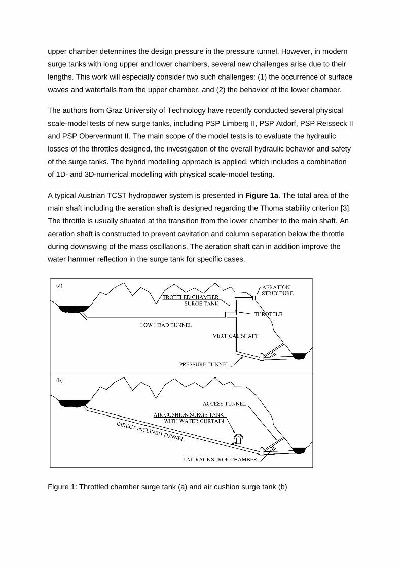
A typical Austrian TCST hydropower system is presented in Figure 1a. The total area of the
main shaft including the aeration shaft is designed regarding the Thoma stability criterion [3].
The throttle is usually situated at the transition from the lower chamber to the main shaft. An
aeration shaft is constructed to prevent cavitation and column separation below the throttle
during downswing of the mass oscillations. The aeration shaft can in addition improve the
water hammer reflection in the surge tank for specific cases.
Figure 1: Throttled chamber surge tank (a) and air cushion surge tank (b)
In Norway, the ACST is regarded as state-of-the-art. This surge tank is constructed as an
excavated underground rock cavern filled with pressurized air. A total of ten ACSTs exist in
Norway, and three are constructed in China [4], [5]. Figure 1b presents a typical ACST
hydropower system.
However, the ACST has not yet been applied on the high-pressure side of hydropower
systems in the alpine region, mainly due to geological reasons. A review of the benefits and
challenges related to application of the ACST in the alpine region is therefore carried out,
and a comparison between the ACST and the TCST is conducted based on a generic
hydropower project.
2 Methods of Surge Tank Investigation
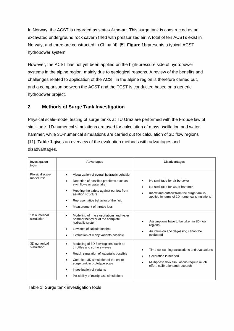
Physical scale-model testing of surge tanks at TU Graz are performed with the Froude law of
similitude. 1D-numerical simulations are used for calculation of mass oscillation and water
hammer, while 3D-numerical simulations are carried out for calculation of 3D flow regions
[11]. Table 1 gives an overview of the evaluation methods with advantages and
disadvantages.
Investigation tools
Advantages Disadvantages
Physical scale-model test
Visualization of overall hydraulic behavior
Detection of possible problems such as swirl flows or waterfalls
Proofing the safety against outflow from aeration structure
Representative behavior of the fluid
Measurement of throttle loss
No similitude for air behavior
No similitude for water hammer
Inflow and outflow from the surge tank is applied in terms of 1D numerical simulations
1D numerical simulation
Modelling of mass oscillations and water hammer behavior of the complete hydraulic system
Low cost of calculation time
Evaluation of many variants possible
Assumptions have to be taken in 3D-flow regions
Air intrusion and degassing cannot be evaluated
3D numerical simulation
Modelling of 3D-flow regions, such as throttles and surface waves
Rough simulation of waterfalls possible
Complete 3D-simulation of the entire surge tank in prototype scale
Investigation of variants
Possibility of multiphase simulations
Time-consuming calculations and evaluations
Calibration is needed
Multiphase flow simulations require much effort, calibration and research
Table 1: Surge tank investigation tools
It has been experienced that a hybrid modelling approach including a combination of 1D
numerical simulations, 3D numerical simulation to investigate hydraulic details, and physical
model tests is necessary in order to detect and evaluate all the different hydraulic
phenomena occurring in new complex surge tanks.
3 Long Upper Chamber Behavior
Long upper chambers are excavated mainly due to construction benefits. This leads to a
more significant differential effect [2], which improves the damping of the mass oscillations.
This effect increases with the length of the upper chamber, limited by the demand of
complete emptying before the next upswing fills the chamber again.
The upper chambers are constructed as tunnels with free surface flow. In contrast to a lower
chamber, the occurrence of pressurized flow should be avoided. The filling and emptying
process is mainly driven by the inclination and the length of the tunnel. The aeration structure
is established at the transition to the atmosphere, where water spilling is prevented and air
ventilation ensured. The volume of the upper chambers is designed for the volume demand
regarding multi shifting load-case operation of the power plant [1].
As long upper chambers are governed by free surface flow conditions, the occurrence of a
significant surface wave should be expected during filling. In addition, the emptying process
results in column separation between the upper chamber and the main shaft, which results in
a waterfall. The size of a filling wave in order to prevent overflow can be reduced by
structural means such as steps or beams [6], and by optimum inclination of the upper
chamber. In the example of surge tank Krespa for PSP Obervermunt II, an inclination of
1.5 % was found for an appropriate performance.
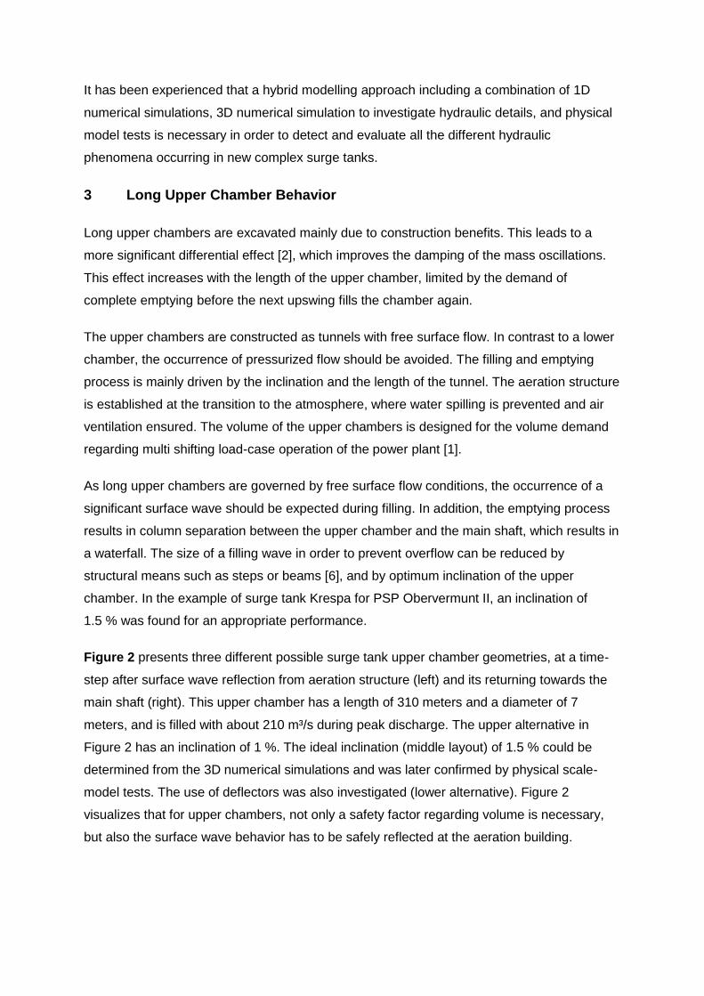
Figure 2 presents three different possible surge tank upper chamber geometries, at a time-
step after surface wave reflection from aeration structure (left) and its returning towards the
main shaft (right). This upper chamber has a length of 310 meters and a diameter of 7
meters, and is filled with about 210 m³/s during peak discharge. The upper alternative in
Figure 2 has an inclination of 1 %. The ideal inclination (middle layout) of 1.5 % could be
determined from the 3D numerical simulations and was later confirmed by physical scale-
model tests. The use of deflectors was also investigated (lower alternative). Figure 2
visualizes that for upper chambers, not only a safety factor regarding volume is necessary,
but also the surface wave behavior has to be safely reflected at the aeration building.
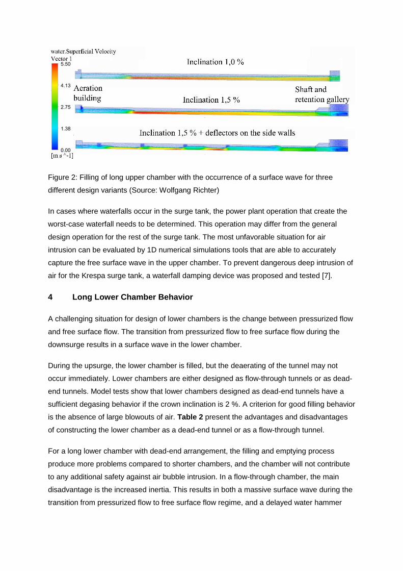
Figure 2: Filling of long upper chamber with the occurrence of a surface wave for three
different design variants (Source: Wolfgang Richter)
In cases where waterfalls occur in the surge tank, the power plant operation that create the
worst-case waterfall needs to be determined. This operation may differ from the general
design operation for the rest of the surge tank. The most unfavorable situation for air
intrusion can be evaluated by 1D numerical simulations tools that are able to accurately
capture the free surface wave in the upper chamber. To prevent dangerous deep intrusion of
air for the Krespa surge tank, a waterfall damping device was proposed and tested [7].
4 Long Lower Chamber Behavior
A challenging situation for design of lower chambers is the change between pressurized flow
and free surface flow. The transition from pressurized flow to free surface flow during the
downsurge results in a surface wave in the lower chamber.
During the upsurge, the lower chamber is filled, but the deaerating of the tunnel may not
occur immediately. Lower chambers are either designed as flow-through tunnels or as dead-
end tunnels. Model tests show that lower chambers designed as dead-end tunnels have a
sufficient degasing behavior if the crown inclination is 2 %. A criterion for good filling behavior
is the absence of large blowouts of air. Table 2 present the advantages and disadvantages
of constructing the lower chamber as a dead-end tunnel or as a flow-through tunnel.
For a long lower chamber with dead-end arrangement, the filling and emptying process
produce more problems compared to shorter chambers, and the chamber will not contribute
to any additional safety against air bubble intrusion. In a flow-through chamber, the main
disadvantage is the increased inertia. This results in both a massive surface wave during the
transition from pressurized flow to free surface flow regime, and a delayed water hammer
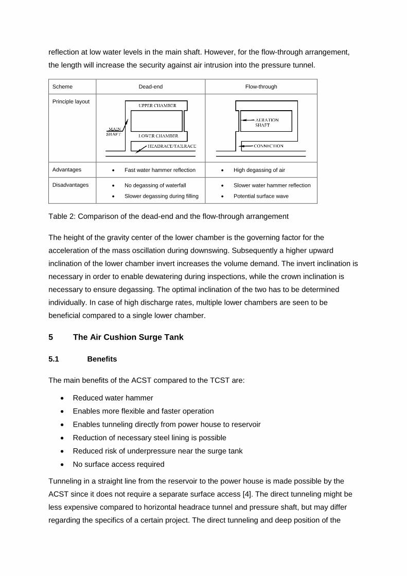
reflection at low water levels in the main shaft. However, for the flow-through arrangement,
the length will increase the security against air intrusion into the pressure tunnel.
Scheme Dead-end Flow-through
Principle layout
Advantages Fast water hammer reflection High degassing of air
Disadvantages No degassing of waterfall
Slower degassing during filling
Slower water hammer reflection
Potential surface wave
Table 2: Comparison of the dead-end and the flow-through arrangement
The height of the gravity center of the lower chamber is the governing factor for the
acceleration of the mass oscillation during downswing. Subsequently a higher upward
inclination of the lower chamber invert increases the volume demand. The invert inclination is
necessary in order to enable dewatering during inspections, while the crown inclination is
necessary to ensure degassing. The optimal inclination of the two has to be determined
individually. In case of high discharge rates, multiple lower chambers are seen to be
beneficial compared to a single lower chamber.
5 The Air Cushion Surge Tank
5.1 Benefits
The main benefits of the ACST compared to the TCST are:
Reduced water hammer
Enables more flexible and faster operation
Enables tunneling directly from power house to reservoir
Reduction of necessary steel lining is possible
Reduced risk of underpressure near the surge tank
No surface access required
Tunneling in a straight line from the reservoir to the power house is made possible by the
ACST since it does not require a separate surface access [4]. The direct tunneling might be
less expensive compared to horizontal headrace tunnel and pressure shaft, but may differ
regarding the specifics of a certain project. The direct tunneling and deep position of the
ACST also avoids potential problems regarding topography. A topography with too high or
too low overburden in the position of the surge tank has been the main reason for selecting
the ACST in many of the Norwegian hydropower plants [8].
In addition, recent refurbishments and replacements of steel lined pressure shafts (steel
ageing) in Austria and Norway are showing that the pressure shaft lifetime is significantly
lower compared to the overall lifetime of the hydropower plant (Kaunertal power plant ~ 50
years, Kaprun power plant ~ 60 years, and Suldal I power plant ~ 45 years). In comparison,
steel lining may be reduced for deep tunneling due to higher rock stress, which protect
against hydraulic jacking.
ACSTs are constructed without surface access, reducing the excavated volume and the
environmental impact on the surface. Hydropower projects are often developed in areas of
natural beauty where reduced environmental impact is of high value. Construction works and
transport on challenging terrain during construction of the surface access is also avoided.
The sum of the benefits provided by the ACST could in some cases make this solution more
economic and environmentally favorable compared to the TCST with adit tunnels.
5.2 Challenges in the Alpine Region
There are several challenges concerning the use of an ACST in the alpine region, such as
[12]:
Secure and economic progress of deep tunneling
Requirement to rock quality and strength parameters
Minimum principle rock stress must be higher than air pressure
Stability of the excavated rock cavern
Control of air leakage
Higher demand of monitoring and maintenance
Time consumption of air filling procedure
Use of the ACST requires that the minimum principle stress (σ3>σw) in the rock is higher than
the static air pressure, in order to avoid hydraulic fracturing of the rock. It should be noted
that the weakest point of the cavern, and not the average should be considered. The
Norwegian geology is known to have relatively high horizontal stresses due to tectonic
movements in the past, and this reduces the required rock cover in order to gain satisfactory
stress levels [9]. In general, construction of an ACST in the Alps will require a deeper
placement in the rock, and the site-specific geological conditions needs to be studied in order
to evaluate optimal placement of these facilities. Final placement of the ACST needs to be
decided based on hydraulic jacking tests in the tunnel during excavation.
A common misconception is that use of the ACST requires high rock strength and quality,
while it is the minimum principle stress that is important. An example is the ACST for Brattset
power plant, which successfully is constructed in graphitic phyllite rock [8].
To ensure stability of the excavated rock cavern, more use of rock support is expected in the
Alps compared to Norway due to the rock mass quality. However, the application of the
ACST in China [5] proves that the solution is not exclusive for Norwegian geology. Common
measures to increase rock mass stability should be sufficient to enable the use of ACST in
some regions of the Alps. However, in areas with very poor rock mass quality, grouting may
be used as an extended measure. For small ACSTs, the use of steel tanks is also possible,
as applied in the alpine PSP Kops II in Austria. Steel tanks should however be avoided for
larger caverns due to the high costs compared to common support measures such as
sprayed concrete and rock bolting. The air leakage is dependent on rock mass permeability,
which increases with the number of cracks and joints in the rock. Hard rock is known to have
higher permeability compared to softer rocks due to rougher transitions in joints and cracks.
Air tightness may however be ensured by a water curtain as described in [4]. The water
curtain consist of boreholes drilled in the rock above the ACST, which are filled with
pressurized water in order to increase the groundwater pressure. The pressurized water
have higher pressure compared to the air in the ACST resulting in water leakage into the
ACST, instead of air leakage out. Water curtains have been applied for hydropower,
compressed air energy storage and LPG storage in several countries successfully [8]. After
construction, the ACST requires monitoring in order to ensure that the air pressure and water
level is within limited boundaries. A redundant and robust monitoring scheme is necessary.
For large ACSTs the filling time of the air pocket needs to be considered. The filling time of
Kvilldal ACST (80 000 m³ of air with 40 bar pressure) is several weeks, which may result in
water losses given high inflow and high reservoir water level. The experience from existing
ACST show that higher investment in air compressor capacity and piping connection is
valuable in order to reduce stop-time of the power plant during tunnel emptying.
6 Comparison
In order to compare the ACST against the TCST, a generic hydropower scheme is
evaluated. A principle drawing of the two alternatives is seen in Figure 1, while Table 3
presents the properties of the schemes. The TCST scheme is designed with a horizontal
headrace tunnel, and a pressure shaft. The ACST scheme incorporates a direct inclined
tunnel without pressure shaft. Similar properties for both schemes are head of 600 m,
discharge of 100 m3/s, tunnel cross section area of 60 m2, and shaft diameter of 6 m. The
comparison is made on excavated rock volume, exposed rock surface in the tunnel system,
and design pressure.
One should note that 5 % increased tunnel length is assumed in the TCST scheme due to
the possibility of a more direct aligned tunnel in the ACST scheme. The shaft of the TCST
has a minimum area of 45 m2 given from Thoma [3], while the upper and lower chambers
have 500 m2 each. The ACST is designed with the minimum volume occurring to the Svee
[10] criteria. Both schemes include a throttle with headloss factor 1:5 in upswing and
downswing direction respectively. For calculation of the thermodynamic behavior of the air,
the adiabatic exponent of 1.4 is applied [4].
TCST ACST
Headrace length (m) 10 500 10 000
Pressure shaft length (m) 600 x
Pressure tunnel length (m) 500 500
Surface access tunnels (adits)(m) 1 000 x
Surge tank volume (m3) 16 000 75 000
Resulting design pressure (mWC) 680 670
Rock surface area surge chamber (m2) 7 500 12 300
Reflection time of water hammer (s) 1.8 1.0
Water inertia time constant (s) 0.6 0.3
Total amount of rock surface area (m2) 350 000 301 000
Total amount of excavated volume (m3) 744 000 711 000
Table 3: Comparison of the air cushion and the throttled chamber surge tank schemes
As shown in Table 3, both the total amount of excavated rock volume and resulting exposed
rock surface is higher for the TCST scheme compared to the ACST scheme. Less exposed
rock surface for the ACST scheme indicates that there is less need for rock support and
lining.
It should however be noted that when considered isolated, the volume of the ACST is larger
than the volume of the TCST. This implies that for hydropower projects where the headrace
length of the two alternatives are more similar, the TCST scheme will be more beneficial.
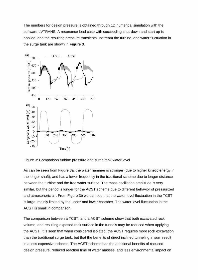
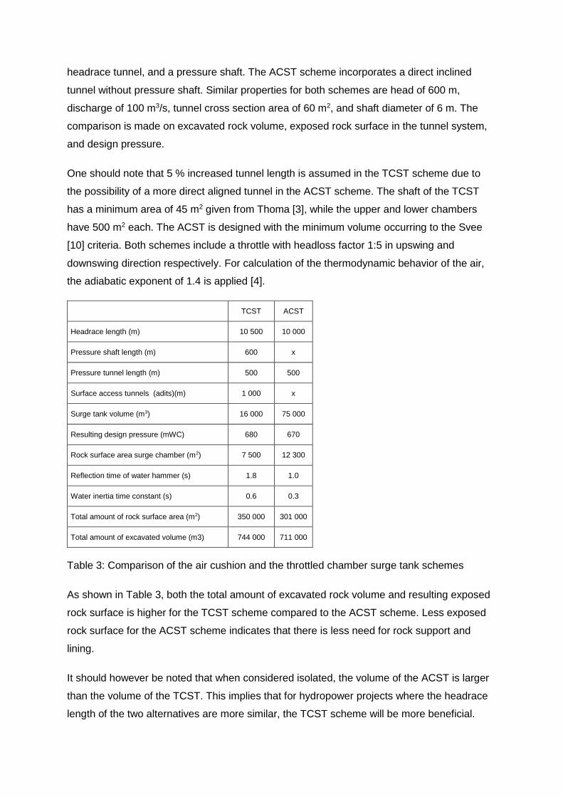
The numbers for design pressure is obtained through 1D numerical simulation with the
software LVTRANS. A resonance load case with succeeding shut-down and start up is
applied, and the resulting pressure transients upstream the turbine, and water fluctuation in
the surge tank are shown in Figure 3.
Figure 3: Comparison turbine pressure and surge tank water level
As can be seen from Figure 3a, the water hammer is stronger (due to higher kinetic energy in
the longer shaft), and has a lower frequency in the traditional scheme due to longer distance
between the turbine and the free water surface. The mass oscillation amplitude is very
similar, but the period is longer for the ACST scheme due to different behavior of pressurized
and atmospheric air. From Figure 3b we can see that the water level fluctuation in the TCST
is large, mainly limited by the upper and lower chamber. The water level fluctuation in the
ACST is small in comparison.
The comparison between a TCST, and a ACST scheme show that both excavated rock
volume, and resulting exposed rock surface in the tunnels may be reduced when applying
the ACST. It is seen that when considered isolated, the ACST requires more rock excavation
than the traditional surge tank, but that the benefits of direct inclined tunneling in sum result
in a less expensive scheme. The ACST scheme has the additional benefits of reduced
design pressure, reduced reaction time of water masses, and less environmental impact on
the surface due to fewer surface access tunnels. However, site-specific variation in
topography will always have key influence to which solution is most beneficial.
7 Conclusion
Modern pumped storage plants with increasing water discharge request increasingly larger
surge tank systems. Simple scaling of available schemes lead to increased challenges in
terms of water hammer reflection, air intrusion, and filling and emptying of chambers. To
mitigate negative effects, measures such as multiple chamber design, waterfall damping
devices, steps and beams, optimized chamber inclination, and aeration shafts are seen to
improve the hydraulic behavior significantly.
From the experience of several physical model studies at TU Graz, it is concluded that the
hybrid modelling approach is necessary in order to detect and accurately capture all the
different hydraulic phenomena occurring in new complex surge tanks to allow highest
flexibility during operation.
A review of the benefits of the ACST compared to the TCST shows that the ACST might be
more beneficial for certain hydropower projects, and especially for problematic topographies.
The limitation for application in alpine projects has so far been the uncertainty regarding
geology. It is concluded that application of ACST in the alpine region may be possible with
modern rock engineering technology, but should be selected for projects where the benefits
are high. For projects where the benefits of the ACST is not high, the TCST scheme with a
long low head tunnel and pressure shaft should be selected. This is to better cope with
uncertainties regarding geology, and the operational challenges of storing pressurized air in
the tunnel system.
Acknowledgements
Vorarlberger Illwerke AG supported the investigation of a long upper chamber. The authors
are very thankful for the valuable process and friendly-constructive communication. Ass.
Prof. Helmut Knoblauch and Ass. Prof. Josef Schneider for great leading of the high head
model tests at TU Graz. The Center for Environmental Design of Renewable Energy
(CEDREN) have given economical support.
Authors
M.Sc. Kaspar Vereide
Norwegian University of Science and Technology
Institute of Hydraulic and Environmental Engineering
S.P. Andersens veg 5
7491 Trondheim, Norway
Dipl.-Ing. Wolfgang Richter
Graz University of Technology
Institute of Hydraulic Engineering and Water Resources Management
Stremayrgasse 10/II
A-8020 Graz, Austria
Univ.-Prof. Dipl.-Ing. Dr.techn. Gerald Zenz
Graz University of Technology
Institute of Hydraulic Engineering and Water Resources Management
Stremayrgasse 10/II
A-8020 Graz, Austria
Prof. Leif Lia
Norwegian University of Science and Technology
Institute of Hydraulic and Environmental Engineering
S.P. Andersens veg 5
7491 Trondheim, Norway
Literature
[1] Heigert, G.: Drossel – und – Differential – Wasserschlösser von Regelkraftwerken mit
Freier Betriebsführung. Dissertation, Technische Hochschule Wien, 1970.
[2] Johnson, R: The Surge Tank in Water Power Plants. In: Trans. ASME 30 (1908), P.
443-474.
[3] Thoma, D: Zur Theorie des Wasserschlosses bei selbsttätig geregelten
Turbinenanlagen. Dissertation, Technische Hochschule München: R.Oldenburg,
1910.
[4] Goodal, D.C.; Kjørholt, H.; Tekle, T.; Broch, E.: Air Cushion Surge Chambers for
Underground Hydropower Plants. In: Water Power and Dam Construction (1988),
Issue 11, P. 29-34.
[5] Hu, J.; Zhang, J.; Suo, L.; Fang, J.: Advance in Research on Air Cushion Surge
Chamber in Hydropower Plant, In: Proceedings of IMECE2007 (2007), P. 11-15.
[6] Larcher, M.; Knoblauch, H.; Heigerth, G.; Wagner E.; Stering, P.: Instationäre Füll-
und Entleervorgänge bei der Auslegung der Oberkammer des Wasserschlosses
Limberg II, Wasserwirtschaft Nr.4 (2010), P. 107-109.
[7] Richter, W.; Schneider, J.; Zenz, G.; Innerhofer, G.: Hybrid Modelling and
Development of a long Upper Chamber in a Surge Tank, In: Proceedings of Hydro
Congress (2013), Innsbruck.
[8] Kjørholt, H.; Dahlø, T.: Geotechnical Design of Air Cushion Surge Chambers, In:
Hydropower’92, Balkema, Rotterdam, 1992.
[9] Nilsen, B.; Thidemann, A.: Hydropower Development - Rock Engineering, Trondheim,
Tapir Press, 1993.
[10] Svee, R.: Surge Chamber with Enclosed Compressed Air Cushion. Proc. 1st. Int.
Conf. on Pressure Surges (1972), British Hydromechanics Research Association,
Bedford, P. 15-24.
[11] Richter W.; Schneider J.; Knoblauch H.; Zenz G.: Behavior of Long Chambers in
Surge Tanks. Proc. of 18th International Seminar on Hydropower plants (2014),
Vienna.
[12] Vereide, K.; Leif, L.; Richter, W.: Benefits of the Air Cushion Chamber for Alpine
Hydropower Plants. Proc. of 18th International Seminar on Hydropower plants (2014),
Vienna.