type 2 surge arrester type 3 surge arrester - tracon electric
TRANSCRIPT
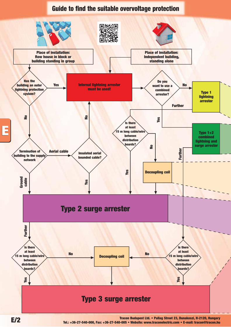
E/2
Place of installation:Row house in block or
building standing in group
Place of installation:Independent building,
standing alone
Has the building an outer
lightning protectionsystem?
Termination of building to the supply
network
Is there at least
15 m long cable/wirebetween
distribution boards?
Is there at least
15 m long cable/wirebetween
distribution boards?
Is there at least
15 m long cable/wirebetween
distribution boards?
Insulated aerial bounded cable?
Decoupling coil
Do you want to use a
combined arrester?
Decoupling coil
Type 1 lightningarrester
Type 1+2combined
lightning andsurge arrester
Yes No
No No
Further
NoGr
ound
cabl
e
Yes
Yes
Furt
her
Furt
her
Yes
Yes
Yes
No
NoInternal lightning arrester
must be used!
Type 2 surge arrester
Type 3 surge arrester
Guide to find the suitable overvoltage protection
Aerial cable
Tracon Budapest Ltd. • Pallag Street 23, Dunakeszi, H-2120, Hungary Tel.: +36-27-540-000, Fax: +36-27-540-005 • Website: www.traconelectric.com • E-mail: [email protected]
E/3
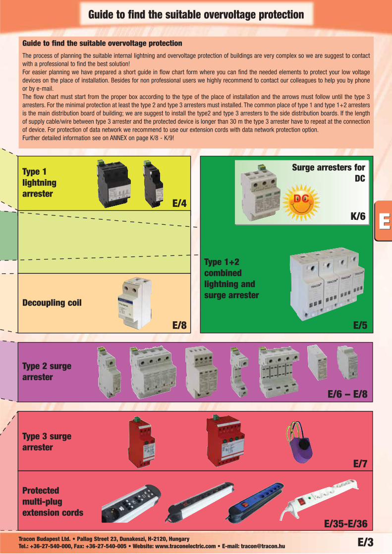
E/4
E/8 E/5
E/6 – E/8
E/7
E/35-E/36
K/6
Guide to find the suitable overvoltage protection
The process of planning the suitable internal lightning and overvoltage protection of buildings are very complex so we are suggest to contactwith a professional to find the best solution! For easier planning we have prepared a short guide in flow chart form where you can find the needed elements to protect your low voltagedevices on the place of installation. Besides for non professional users we highly recommend to contact our colleagues to help you by phoneor by e-mail.The flow chart must start from the proper box according to the type of the place of installation and the arrows must follow until the type 3arresters. For the minimal protection at least the type 2 and type 3 arresters must installed. The common place of type 1 and type 1+2 arrestersis the main distribution board of building; we are suggest to install the type2 and type 3 arresters to the side distribution boards. If the lengthof supply cable/wire between type 3 arrester and the protected device is longer than 30 m the type 3 arrester have to repeat at the connectionof device. For protection of data network we recommend to use our extension cords with data network protection option.Further detailed information see on ANNEX on page K/8 - K/9!
Guide to find the suitable overvoltage protection
Tracon Budapest Ltd. • Pallag Street 23, Dunakeszi, H-2120, Hungary Tel.: +36-27-540-000, Fax: +36-27-540-005 • Website: www.traconelectric.com • E-mail: [email protected]
Type 1 lightningarrester
Decoupling coil
Type 2 surgearrester
Type 3 surgearrester
Protected multi-plugextension cords
Type 1+2combinedlightning andsurge arrester
Surge arresters forDC
W
90
6.7
5843
45
E/4
K/6
Tracon Budapest Ltd. • Pallag Street 23, Dunakeszi, H-2120, Hungary Tel.: +36-27-540-000, Fax: +36-27-540-005 • Website: www.traconelectric.com • E-mail: [email protected]
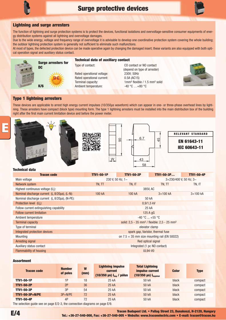
Technical data of auxiliary contactType of contact: CO contact or NO contact
(depend on type of arrester)Rated operational voltage: 230V; 50HzRated operational current: 0.5A (AC15)Terminal capacity: 1mm² flexible / 1.5 mm² solidAmbient temperature: -40 °C …+80 °C
Lightning and surge arresters The function of lightning and surge protection systems is to protect the devices, functional isolations and overvoltage-sensitive consumer equipments of ener-gy distribution systems against all lightning and overvoltage damages. Due to the wide energy, voltage and frequency range of overvoltage it is advisable to develop one coordinative protection system covering the whole building;the outdoor lightning protection system is generally not sufficient to eliminate such malfunctions. At most of types, the defected protection device can be made operative again by changing the damaged insert; these variants are also equipped with both opti-cal operation signal and auxiliary status contact.
Tracon code TTV1-50-1P TTV1-50-2P TTV1-50-3P… TTV1-50-4PMain voltage 230 V, 50 Hz; 1~ 3×230/400 V, 50 Hz; 3~Network system TN, TT TN, IT TN, TT TN, ITHighest continuous voltage (Uc): 385V, ACNominal discharge current (In 8/20μs), (L-N): 100 kA 100 kA 3×100 kA 3×100 kANominal discharge current (In 8/20μs), (N-PE): 50 kAProtection level (Up): 0,9/1,5 kVFollow current extinguishing capability 25 kAFollow current limitation 125 A gGAmbient temperature -40 °C ... +55 °CTerminal capacity solid: 2,5 - 35 mm² / flexible: 2,5 - 25 mm²Type of terminal elevator clampIntegrated protection devices spark gap, Varistor, thermal fuseMounting on 7.5 × 35 mm size mounting rail (EN 50022)Arresting signal Red optical signalAuxiliary status contact Integrated (1 pc NO contact)Flammability of housing UL94-V0
Type 1 lightning arrestersThese devices are applicable to arrest high energy current impulses (10/350μs waveform) which can appear in one- or three-phase overhead lines by light-ning. These arresters have compact (block type) mounting form. The type 1 lightning arresters must be installed into the main distribution box of the buildingright after the first main current limitation device and before the power meter.
Technical data
Number WLightning impulse Total Lightning
Tracon codeof poles (mm)
current impulse current Color Type(10/350 μs) Iimp / pólus (10/350 μs) Iimptotal
TTV1-50-1P 1P 18 25 kA 50 kA black compactTTV1-50-2P 2P 36 25 kA 50 kA black compactTTV1-50-3P 3P 54 25 kA 50 kA black compactTTV1-50-3P+N/PE 3P+N/PE 72 25 kA 50 kA black compactTTV1-50-4P 4P 72 25 kA 50 kA black compact
Assortment
The selection guide see on page E/2-3, the connection diagrams on page E/9.
Surge protective devices
EN 61643-11IEC 60643-11
R E L E V A N T S TA N D A R D
Surge arresters forDC
W
90
6.7
5843
45
E/5Tracon Budapest Ltd. • Pallag Street 23, Dunakeszi, H-2120, Hungary Tel.: +36-27-540-000, Fax: +36-27-540-005 • Website: www.traconelectric.com • E-mail: [email protected]
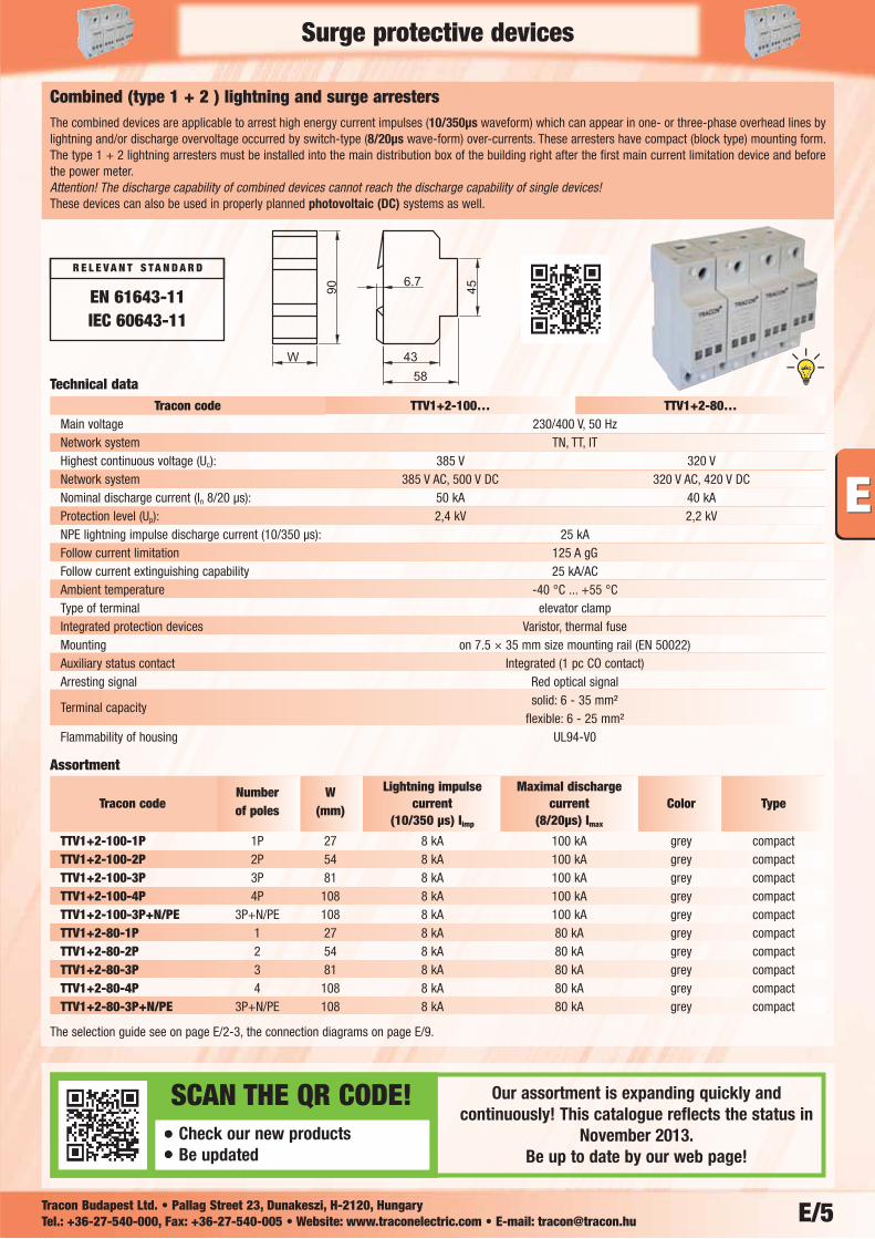
Combined (type 1 + 2 ) lightning and surge arrestersThe combined devices are applicable to arrest high energy current impulses (10/350μs waveform) which can appear in one- or three-phase overhead lines bylightning and/or discharge overvoltage occurred by switch-type (8/20μs wave-form) over-currents. These arresters have compact (block type) mounting form.The type 1 + 2 lightning arresters must be installed into the main distribution box of the building right after the first main current limitation device and beforethe power meter. Attention! The discharge capability of combined devices cannot reach the discharge capability of single devices!These devices can also be used in properly planned photovoltaic (DC) systems as well.
Tracon code TTV1+2-100… TTV1+2-80…Main voltage 230/400 V, 50 HzNetwork system TN, TT, ITHighest continuous voltage (Uc): 385 V 320 VNetwork system 385 V AC, 500 V DC 320 V AC, 420 V DCNominal discharge current (In 8/20 μs): 50 kA 40 kAProtection level (Up): 2,4 kV 2,2 kVNPE lightning impulse discharge current (10/350 μs): 25 kAFollow current limitation 125 A gGFollow current extinguishing capability 25 kA/ACAmbient temperature -40 °C ... +55 °CType of terminal elevator clampIntegrated protection devices Varistor, thermal fuseMounting on 7.5 × 35 mm size mounting rail (EN 50022)Auxiliary status contact Integrated (1 pc CO contact)Arresting signal Red optical signal
Terminal capacity solid: 6 - 35 mm² flexible: 6 - 25 mm²
Flammability of housing UL94-V0
Technical data
Number W Lightning impulse Maximal dischargeTracon code of poles (mm) current current Color Type
(10/350 μs) Iimp (8/20μs) Imax
TTV1+2-100-1P 1P 27 8 kA 100 kA grey compactTTV1+2-100-2P 2P 54 8 kA 100 kA grey compactTTV1+2-100-3P 3P 81 8 kA 100 kA grey compactTTV1+2-100-4P 4P 108 8 kA 100 kA grey compactTTV1+2-100-3P+N/PE 3P+N/PE 108 8 kA 100 kA grey compactTTV1+2-80-1P 1 27 8 kA 80 kA grey compactTTV1+2-80-2P 2 54 8 kA 80 kA grey compactTTV1+2-80-3P 3 81 8 kA 80 kA grey compactTTV1+2-80-4P 4 108 8 kA 80 kA grey compactTTV1+2-80-3P+N/PE 3P+N/PE 108 8 kA 80 kA grey compact
Assortment
The selection guide see on page E/2-3, the connection diagrams on page E/9.
Surge protective devices
EN 61643-11IEC 60643-11
R E L E V A N T S TA N D A R D
Our assortment is expanding quickly andcontinuously! This catalogue reflects the status in
November 2013.Be up to date by our web page!
SCAN THE QR CODE!Check our new productsBe updated
W
90
6.7
5843
45
E/6 Tracon Budapest Ltd. • Pallag Street 23, Dunakeszi, H-2120, Hungary Tel.: +36-27-540-000, Fax: +36-27-540-005 • Website: www.traconelectric.com • E-mail: [email protected]
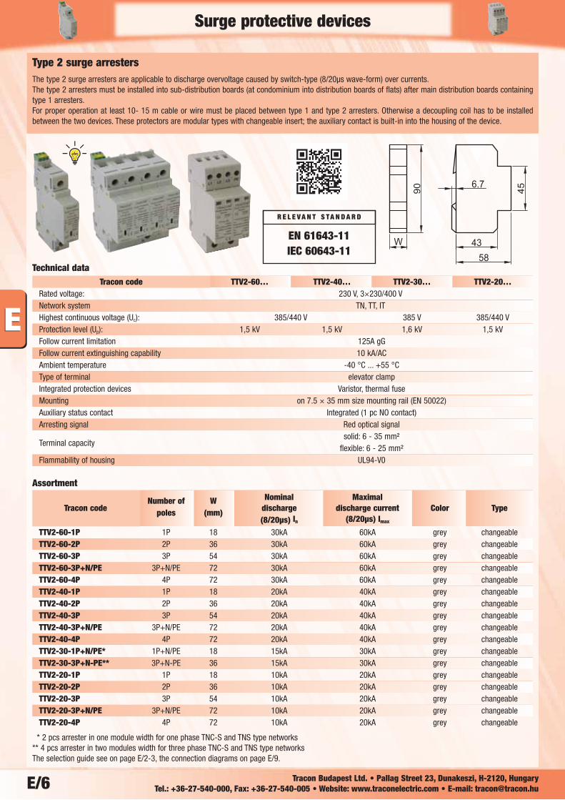
Type 2 surge arrestersThe type 2 surge arresters are applicable to discharge overvoltage caused by switch-type (8/20μs wave-form) over currents.The type 2 arresters must be installed into sub-distribution boards (at condominium into distribution boards of flats) after main distribution boards containingtype 1 arresters. For proper operation at least 10- 15 m cable or wire must be placed between type 1 and type 2 arresters. Otherwise a decoupling coil has to be installedbetween the two devices. These protectors are modular types with changeable insert; the auxiliary contact is built-in into the housing of the device.
Number of W Nominal Maximal Tracon code poles (mm) discharge discharge current Color Type
(8/20μs) In (8/20μs) Imax
TTV2-60-1P 1P 18 30kA 60kA grey changeableTTV2-60-2P 2P 36 30kA 60kA grey changeableTTV2-60-3P 3P 54 30kA 60kA grey changeableTTV2-60-3P+N/PE 3P+N/PE 72 30kA 60kA grey changeableTTV2-60-4P 4P 72 30kA 60kA grey changeableTTV2-40-1P 1P 18 20kA 40kA grey changeableTTV2-40-2P 2P 36 20kA 40kA grey changeableTTV2-40-3P 3P 54 20kA 40kA grey changeableTTV2-40-3P+N/PE 3P+N/PE 72 20kA 40kA grey changeableTTV2-40-4P 4P 72 20kA 40kA grey changeableTTV2-30-1P+N/PE* 1P+N/PE 18 15kA 30kA grey changeableTTV2-30-3P+N-PE** 3P+N-PE 36 15kA 30kA grey changeableTTV2-20-1P 1P 18 10kA 20kA grey changeableTTV2-20-2P 2P 36 10kA 20kA grey changeableTTV2-20-3P 3P 54 10kA 20kA grey changeableTTV2-20-3P+N/PE 3P+N/PE 72 10kA 20kA grey changeableTTV2-20-4P 4P 72 10kA 20kA grey changeable
Assortment
* 2 pcs arrester in one module width for one phase TNC-S and TNS type networks** 4 pcs arrester in two modules width for three phase TNC-S and TNS type networksThe selection guide see on page E/2-3, the connection diagrams on page E/9.
Tracon code TTV2-60… TTV2-40… TTV2-30… TTV2-20…Rated voltage: 230 V, 3×230/400 VNetwork system TN, TT, ITHighest continuous voltage (Uc): 385/440 V 385 V 385/440 VProtection level (Up): 1,5 kV 1,5 kV 1,6 kV 1,5 kVFollow current limitation 125A gGFollow current extinguishing capability 10 kA/ACAmbient temperature -40 °C ... +55 °CType of terminal elevator clampIntegrated protection devices Varistor, thermal fuseMounting on 7.5 × 35 mm size mounting rail (EN 50022)Auxiliary status contact Integrated (1 pc NO contact)Arresting signal Red optical signal
Terminal capacitysolid: 6 - 35 mm²
flexible: 6 - 25 mm²Flammability of housing UL94-V0
Technical data
Surge protective devices
EN 61643-11IEC 60643-11
R E L E V A N T S TA N D A R D
W
90
6.7
5843
45
13
23
34
15
5
E/7Tracon Budapest Ltd. • Pallag Street 23, Dunakeszi, H-2120, Hungary Tel.: +36-27-540-000, Fax: +36-27-540-005 • Website: www.traconelectric.com • E-mail: [email protected]
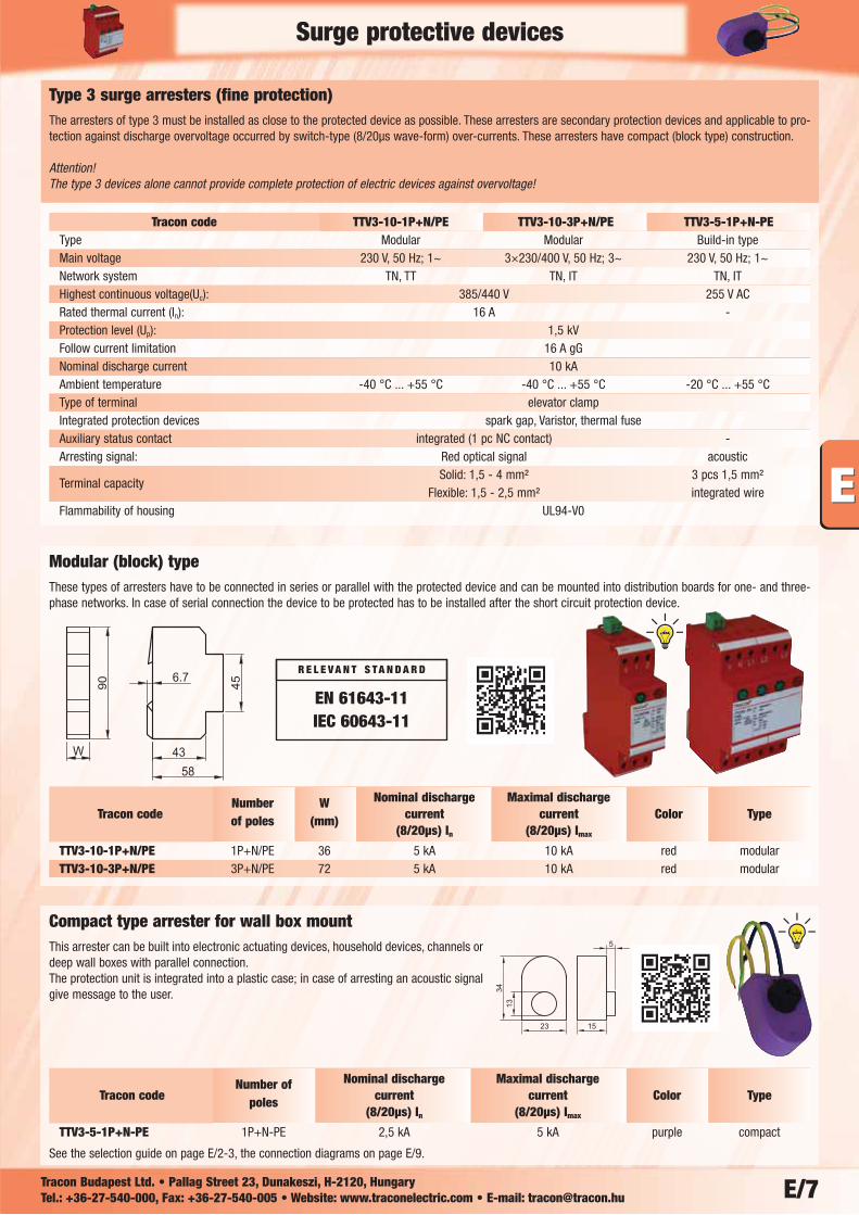
Number W Nominal discharge Maximal discharge Tracon code of poles (mm) current current Color Type
(8/20μs) In (8/20μs) Imax
TTV3-10-1P+N/PE 1P+N/PE 36 5 kA 10 kA red modularTTV3-10-3P+N/PE 3P+N/PE 72 5 kA 10 kA red modular
Number of Nominal discharge Maximal discharge Tracon code poles current current Color Type
(8/20μs) In (8/20μs) Imax
TTV3-5-1P+N-PE 1P+N-PE 2,5 kA 5 kA purple compact
See the selection guide on page E/2-3, the connection diagrams on page E/9.
Type 3 surge arresters (fine protection)The arresters of type 3 must be installed as close to the protected device as possible. These arresters are secondary protection devices and applicable to pro-tection against discharge overvoltage occurred by switch-type (8/20μs wave-form) over-currents. These arresters have compact (block type) construction.
Attention! The type 3 devices alone cannot provide complete protection of electric devices against overvoltage!
Tracon code TTV3-10-1P+N/PE TTV3-10-3P+N/PE TTV3-5-1P+N-PEType Modular Modular Build-in typeMain voltage 230 V, 50 Hz; 1~ 3×230/400 V, 50 Hz; 3~ 230 V, 50 Hz; 1~Network system TN, TT TN, IT TN, ITHighest continuous voltage(Uc): 385/440 V 255 V ACRated thermal current (In): 16 A -Protection level (Up): 1,5 kVFollow current limitation 16 A gGNominal discharge current 10 kAAmbient temperature -40 °C ... +55 °C -40 °C ... +55 °C -20 °C ... +55 °CType of terminal elevator clampIntegrated protection devices spark gap, Varistor, thermal fuseAuxiliary status contact integrated (1 pc NC contact) -Arresting signal: Red optical signal acoustic
Terminal capacitySolid: 1,5 - 4 mm² 3 pcs 1,5 mm²
Flexible: 1,5 - 2,5 mm² integrated wireFlammability of housing UL94-V0
Modular (block) typeThese types of arresters have to be connected in series or parallel with the protected device and can be mounted into distribution boards for one- and three-phase networks. In case of serial connection the device to be protected has to be installed after the short circuit protection device.
Compact type arrester for wall box mountThis arrester can be built into electronic actuating devices, household devices, channels ordeep wall boxes with parallel connection. The protection unit is integrated into a plastic case; in case of arresting an acoustic signalgive message to the user.
Surge protective devices
EN 61643-11IEC 60643-11
R E L E V A N T S TA N D A R D
2%
22%3%5%
15% 28%
25%
�
�
�
�
�
�
�
E/8 Tracon Budapest Ltd. • Pallag Street 23, Dunakeszi, H-2120, Hungary Tel.: +36-27-540-000, Fax: +36-27-540-005 • Website: www.traconelectric.com • E-mail: [email protected]
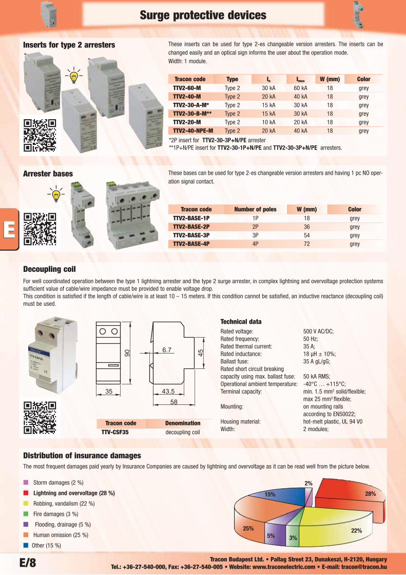
Decoupling coilFor well coordinated operation between the type 1 lightning arrester and the type 2 surge arrester, in complex lightning and overvoltage protection systemssufficient value of cable/wire impedance must be provided to enable voltage drop. This condition is satisfied if the length of cable/wire is at least 10 – 15 meters. If this condition cannot be satisfied, an inductive reactance (decoupling coil)must be used.
Tracon code Type In Imax W (mm) ColorTTV2-60-M Type 2 30 kA 60 kA 18 greyTTV2-40-M Type 2 20 kA 40 kA 18 greyTTV2-30-A-M* Type 2 15 kA 30 kA 18 greyTTV2-30-B-M** Type 2 15 kA 30 kA 18 greyTTV2-20-M Type 2 10 kA 20 kA 18 greyTTV2-40-NPE-M Type 2 20 kA 40 kA 18 grey
These inserts can be used for type 2-es changeable version arresters. The inserts can bechanged easily and an optical sign informs the user about the operation mode. Width: 1 module.
These bases can be used for type 2-es changeable version arresters and having 1 pc NO oper-ation signal contact.
Inserts for type 2 arresters
Arrester bases
Technical dataRated voltage: 500 V AC/DC; Rated frequency: 50 Hz; Rated thermal current: 35 A; Rated inductance: 18 μH ± 10%; Ballast fuse: 35 A gL/gG; Rated short circuit breaking capacity using max. ballast fuse: 50 kA RMS; Operational ambient temperature: -40°C … +115°C; Terminal capacity: min. 1.5 mm2 solid/flexible;
max 25 mm2 flexible; Mounting: on mounting rails
according to EN50022; Housing material: hot-melt plastic, UL 94 V0Width: 2 modules;
Tracon code Number of poles W (mm) ColorTTV2-BASE-1P 1P 18 greyTTV2-BASE-2P 2P 36 greyTTV2-BASE-3P 3P 54 greyTTV2-BASE-4P 4P 72 grey
Tracon code DenominationTTV-CSF35 decoupling coil
*2P insert for TTV2-30-3P+N/PE arrester**1P+N/PE insert for TTV2-30-1P+N/PE and TTV2-30-3P+N/PE arresters.
Distribution of insurance damages
Storm damages (2 %)
Lightning and overvoltage (28 %)
Robbing, vandalism (22 %)
Fire damages (3 %)
Flooding, drainage (5 %)
Human omission (25 %)
Other (15 %)
The most frequent damages paid yearly by Insurance Companies are caused by lightning and overvoltage as it can be read well from the picture below.
Surge protective devices
E/9
Surge protective devices
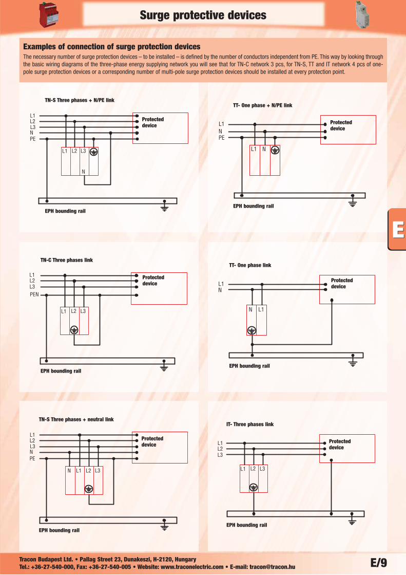
TN-C Three phases link
EPH bounding rail
EPH bounding rail
EPH bounding rail
EPH bounding rail
EPH bounding rail
TT- One phase link
IT- Three phases link
TT- One phase + N/PE linkTN-S Three phases + N/PE link
Protecteddevice
Protecteddevice
Protecteddevice
Protecteddevice
Protecteddevice
EPH bounding rail
TN-S Three phases + neutral link
Protecteddevice
Examples of connection of surge protection devicesThe necessary number of surge protection devices – to be installed – is defined by the number of conductors independent from PE. This way by looking throughthe basic wiring diagrams of the three-phase energy supplying network you will see that for TN-C network 3 pcs, for TN-S, TT and IT network 4 pcs of one-pole surge protection devices or a corresponding number of multi-pole surge protection devices should be installed at every protection point.
Tracon Budapest Ltd. • Pallag Street 23, Dunakeszi, H-2120, Hungary Tel.: +36-27-540-000, Fax: +36-27-540-005 • Website: www.traconelectric.com • E-mail: [email protected]