seismic analysis and design of cold-formed steel structural
TRANSCRIPT

Missouri University of Science and Technology Missouri University of Science and Technology
Scholars' Mine Scholars' Mine
International Specialty Conference on Cold-Formed Steel Structures
(1975) - 3rd International Specialty Conference on Cold-Formed Steel Structures
Nov 24th, 12:00 AM
Seismic Analysis and Design of Cold-formed Steel Structural Seismic Analysis and Design of Cold-formed Steel Structural
Members Members
Suresh G. Pinjarkar
Follow this and additional works at: https://scholarsmine.mst.edu/isccss
Part of the Structural Engineering Commons
Recommended Citation Recommended Citation Pinjarkar, Suresh G., "Seismic Analysis and Design of Cold-formed Steel Structural Members" (1975). International Specialty Conference on Cold-Formed Steel Structures. 3. https://scholarsmine.mst.edu/isccss/3iccfss/3iccfss-session4/3
This Article - Conference proceedings is brought to you for free and open access by Scholars' Mine. It has been accepted for inclusion in International Specialty Conference on Cold-Formed Steel Structures by an authorized administrator of Scholars' Mine. This work is protected by U. S. Copyright Law. Unauthorized use including reproduction for redistribution requires the permission of the copyright holder. For more information, please contact [email protected].
brought to you by COREView metadata, citation and similar papers at core.ac.uk
provided by Missouri University of Science and Technology (Missouri S&T): Scholars' Mine

SEISMIC ANALYSIS AND DESIGN
OF
COLD-FORMED STEEL STRUCTURAL MEMBERS
by
Suresh G. Pinjarkar*, A.M. ASCE
Cold-formed steel structural members are widely used in nuclear
power plant installations. These members are primarily used for carrying
electrical cables and in HVAC duct work. In Seismic Category I Structures,
all electrical cables are often grouped together and carried through con
duits or cable buses in the case of power cables and in cable trays in
the case of control cables. These cable trays and ducts are supported by
the frames or other supporting systems from the slabs, beams, walls, etc.
The primary function of such a system is to support and ensure the safety
of the cables and ducts during the seismic event. lt is essential that
all systems which are vital for the control and safe shutdown of a nuclear
reactor remain functional under the most severe earthquake. The various
components of such a structural system are composed of cold-formed struc
tural steel and are classified as Category I items for seismic analysis
and design.
The seismic response of the secondary system such as cable trays and
ducts is greatly influenced by the nature and type of response of the
* Associate; Wiss, Janney, El:oltner and Associates, Northbrook, Illinois
865

866 THIRD SPECIALTY CONFERENCE
primary structure which supports it. A response spectrum method of
analysis is used to compute forces due to seismic excitations. Due to
an earthquake there is a differential motion between the various elements
and the supporting structure. Since this motion is relatively rapid, it
causes stresses and deformationsin various structural elements. In order
to survive a seismic event the various components must be strong as well
as ductile enough to resist forces and deformations imposed upon it.
The behavior of the secondary system under seismic conditions depends
not only on the earthquake motion to which it is subjected, but on the
properties of the various components of the system. These proper-
ties include member stiffnesses, types of supports, type of connec-
tions, damping characteristics and period of vibration. The purpose of
this paper is to provide a seismic resistant design taking into account
the various factors outlined above. The definition of terms used in this
paper is provided in the Appendix.
TYPES OF MEMBERS
The various types of cold-formed steel structural members more
widely used in Seismic Category I Systems are described below:
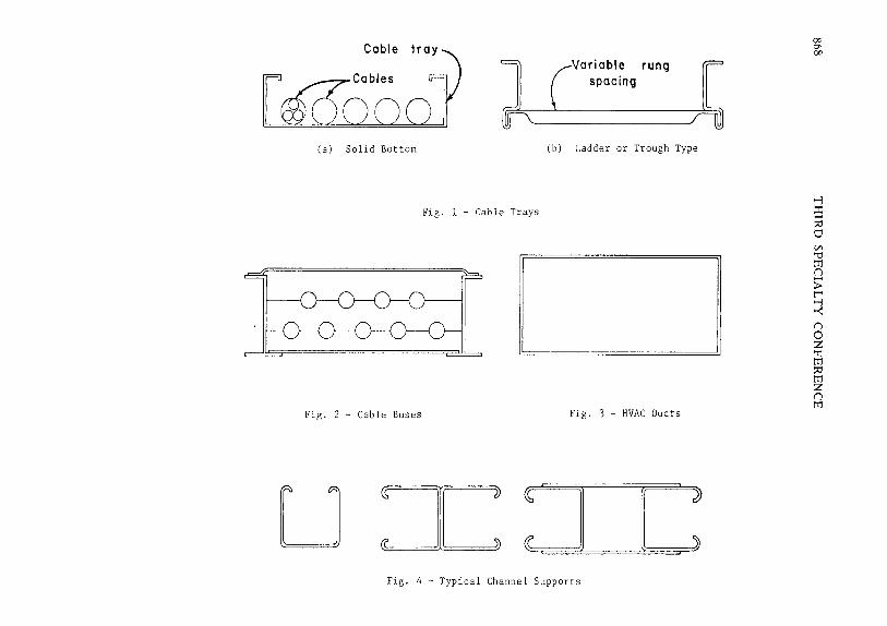
Cable Trays: Cable trays are continuous "U"-shaped members where cables
rest on the bottom of the tray and are held in place by two longitudinal
side walls. There are different types of trays according to their
function and trays from different manufacturers vary in size and shape
and in method of construction.
shown in Fig. 1.
Some of the important types of trays are

SEISMIC ANALYSIS AND DESIGN 867
Cable Buses: Cable buses are used to carry power cables and are of
various types. They are provided with spacers and separate holes for
each cable. See Fig. 2.
HVAC Ducts: These are continuous box type members as shown in Fig. 3.
Support Frames: Various types of channels or combinations of channels (see
Fig. 4) are used as supporting elements for cable trays and HVAC ducts.
These channels permit rigid metal construction without welding or drill-
ing. Standard components are used to create virtually unlimited variety
of support systems. The connections consist of a spring-loaded nut in-
serted anywhere along the continuous channel slot and then secured with
bolts to appropriate fittings. Serrations in the hardened nut engage
channel ridges to produce ~igid vise-like grip. Various support systems
are used to support the cable trays and the ducts as shown in Fig. 5.
ANALYSIS
The seismic analysis of cable tray and HVAC duct systems is
performed by use of the response spectrum or time-history concept of
analysis. The use of response spectrum method, however, provides the
most convenient and direct procedure for seismic analysis. It is there-
fore, necessary to obtain response spectra for various primary supporting
structural elements such as floor slabs and walls, etc. The response
spectra thus obtained is known as in-structure response spectra.
The methods for generating in-structure response spectra are well
documented in the literature. Briefly, a time-history analysis of the
entire structure is performed to obtain the time-history response at the
selected mass points. The next step is to subject
Coble :1 [OOQbOc
Variable rung spacing
(a) Solid Bottom (b) Ladder or Trough Type
Fig. l - Cable Trays
~ Fig. 2 - Cable Buses Fig. 3 - HVAC Ducts
u =c: ~ ~: Fig. 4 - Typical Channel Supports
CP 0' CP
-l :5 ::0 0 C/l "1:1 tr1 (j
:; tl ~ (j
0 z ., tr1 ::0 tr1 z (j tr1

/Fixed or hinged I support
[ 0 0 0 0 J
[ 0 0 0 0 J
·.-Wall
Fig. 5 - Support Systems for Cable Trays, Conduits and HVAC Ducts
[ J
,-Floor slab
Vl
t:l Vl
3:: -(')
> z > t"' -<: ~ Vl
> z 0 0 tTl Vl
Ci z
(7J 0'< \0
870 THIRD SPECIALTY CONFERENCE
a single-degree-freedom system,with the natural frequency range of
interest and various damping ratios,to this time-history motion. The
response spectrum for a particular mass point (supporting structural
element) is obtained by plotting the maximum acceleration against its
frequency. The same procedure is repeated for various damping values.
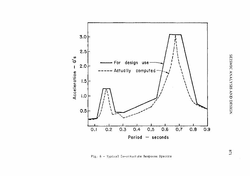
There are a number of uncertainties involved in computing the fre-
quencies and amplitude calculations. These uncertainties are due to
variation in elastic properties of both structure and foundation, ideal-
ization of structure with lumped masses, and elastic properties of dis-
crete parts. These uncertainties are usually accounted for by broadening
of the peak responses as shown in Fig. 6. The resulting smoothed spe·ctra
are used for the purpose of design.
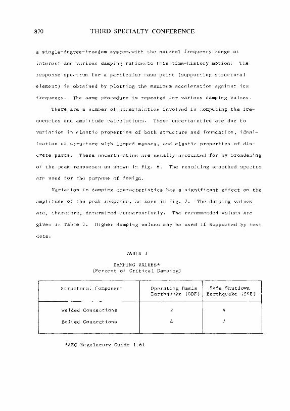
Variation in damping characteristics has a significant effect on the
amplitude of the peak response, as seen in Fig. 7. The damping values
are, therefore, determined conservatively. The recommended values are
given in Table 1. Higher damping values may be used if supported by test
data.
TABLE l
DAMPING VALUES* (Percent of Critical Damping)
Structural Component Operating Earthquake
Welded Connec-tions 2
Bolted Connections 4
*AEC Regulatory Guide 1.61
Basis Safe Shutdown (OBE) Earthquake (SSE)
4
7
3.0
2.5 en
(.!)
2.0 c: 0 - 1.5 c .... Q)
Q)
0 0 1.0 <(
0.5
0.1
-For design use-
----- Actually
\..~ ......... ' , ... ' ...... ,.,""
, , ,,
0.2 0.3 0.4 0.5
', /
I I
I I
I I
I
Period - seconds
Fig. 6 - Typical In-structure Response Spectra
0.7 0.8 0.9
Vl
[:] Vl
~ -n ;I> z ;I> r ~ Vl -Vl
;I> z 0 0 tT1 Vl -0 z
'7J ---1 ......

872
en -c:: ::1
tn
c:: 0
0 ... Q)
Q) (.} (.}
<t
THIRD SPECIALTY CONFERENCE
50 33 20 20.0
10.0 8.0
6.0 5.0 4.0
3.0
2.0
1.0 0.8 I.
0.6 0.5
1--1--
0.4
0.3
0.2
0.1
.05 0.02 0.03 0.05
Frequency {CPS)
10 5.0 3.3 2.0
7£~1% Damping 2% Damping 5% Damping
/h ~0% Damping
r;:l.'l X~ /; ~ v '< \\
\\ I .\ I \ ~ '/ v-··---~~1 '\ \\ ~ v--1'\. \.\
'\ '\ r--~
'\ .\ 1'\
0.1 0.2 0.3 0.5
Period - seconds
Fig. 7 - Typical Response Spectra for Various Damping Values
1.0 0.5
~ \ ~ ~ " '\ ~ ~
""-.. ~
1.0 2.0

SEISMIC ANALYSIS AND DESIGN 873
Recordings of seismic events indicate that the earthquake motions
occur simultaneously in all three directions without consistent relations
among the motions in various directions. Hence, it is necessary to
compute the total effect of all components by taking the square root of
the sum of the squares of the three components of motion (two orthogonal
horizontal and one vertical motion). For the purpose of design, therefore,
the in-structure response spectra are developed for all three components
of earthquake motion. These spectra are developed both for Safe Shutdown
Earthquake (SSE) and Operating Basis Earthquake (OBE).
DESIGN PROCEDURES
The methods and procedures for seismic calculations depend upon the
type of structural component to be analyzed, and accordingly, the analysis
Is divided into two parts:
Rigid Component: In this ··ase the component is rigidly attached to the
supporting element a11d has a 11atural period of vihratio11 eqtial to or less
than 0.02 (or frequency greater than 50). Ir1 tl1is case the componcJlt
simply "rides" along with the support and the acceleration of the compo
nent is the same as that of the support without amplification. The
acceleration to which the component is subjected is assumed to be equal to
the acceleration corresponding to zero period from the in-structure re-
sponse spectrum.
Flexible Component: When the component is flexible there is a resonant
874 THIRD SPECIALTY CONFERENCE
effect between the component and structure. If the component has a
natural frequency close to the resonant frequency of the structure, the
component motion is greatly amplified. Near the point of resonance the
acceleration of the component may be several times that of the supporting
point. The response of flexible components depends upon the stiffness of
various members, type of connections, type of supports and material
characteristics and loads.
The complex flexible systems are analyzed by performing dynamic
analysis. For the purpose of a dynamic analysis the system may be repre
sented by a lumped-mass multi-degree-of-freedom system consisting of a
discrete number of masses connected by a set of mass-free elastic members.
The masses are chosen so that all significant modes are included. Also a
mass is lumped at points where significant concentrated weight is located.
The resulting system is analyzed using response spectrum modal analysis
technicque or time-history analysis. All significant modes are included
in the analysis. A square-root of the sum of the square method criterion
is used i11 combini11g model responses.
The structural system is subjected to the seismic excitations in
three orthogonal directions; namely, two horizontal and one vertical. The
individual responses are combined according to the square-root of the sum
of the square criterion to determine the complete response of the compo
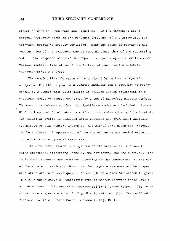
nent structure to an earthquake. An example of a flexible system is given
in Fig. 8 which shows a cantilever type of hanger carrying three levels
of cable trays. This system is represented by 3 lumped masses. The indi
vidua 1 mode shapes are shown in Fig. 8 (d). (e). and (f). The combined
response due to all three modes is shown in Fig. 8(c).

Support
Motion
~
c.___)
t:____1 II [.__J
L...J~I (_1
(a)
Lumped mass model
tbA
~
~
(b)
u
L_j
~
(c)
:!
!....1
l..___..\
1st Mode
(d)
Fig. 8 - Dynamic Analysis of Flexible Systems
+ n +
w
~
2nd Mode
(e)
~ f-J
~
3rd Mode
(f)
Vl tTl v; 3:: I)
> z > r -< Vl
Vl
> z tJ tJ tTl Vl
C1 z
~ ---1 (fo

876 THIRD SPECIALTY CONFERENCE
Pseudo-Dynamic or Equivalent Static Analysis
Since the complete dynamic analysis of the system is quite cumber
some, static analysis based on the dynamic response, also known as pseudo-
dynamic analysis, may be performed under certain conditions. In pseudo-
dynamic analysis the structure is represented by a single-degree-of
freedom system and the period of vibration is computed by simple analytical
methods. The seismic forces are then obtained by multiplying the mass by
the appropriate acceleration and applying it at the center of gravity of
the mass. A detai 1 description of Lhis procedure is given later. The analy
sis could be further simplified by using the peak acceleration value
obtained from the in-structure spectra. This value is multiplied by a
factor of 1.5 to obtain equivalent static loads to account for all modes.
Any simplified analysis which results in equally conservative response is
a] so acceptable.
The various <·ompor1et1ts of tl1e ,·able tray or HVAC du<·t system are de
signed to withstand the effects of dead load, live load, and seismic forces.
The following load conditions are investigated and checked to determine the
most severe cot1dition.
l. Dead Load
2. Dead Load plus Live Load
3. Dead Load plus Safe Shutdown Earthquake (SSE)
4. Dead Load plus Operating Bases Earthquake (OBE)
SEISMIC ANALYSIS AND DESIGN 877
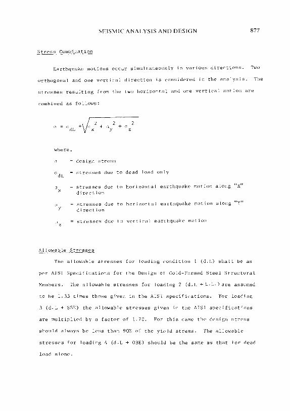
Stress Combination
Earthquake motions occur simultaneously in various directions. Two
orthogonal and one vertical direction is considered in the analysis. The
stresses resulting from the two horizontal and one vertical motio11 are
~ombined as follows:
0 dL
where,
(\
0dL
0 X
(j y
n z
2 2 + n + o y z
design stress
stresses due to dead load only
stresses due to horizontal earthquake motion along "X" direction
stresses due to horizontal earthquake motion along "Y"
direction
stresses due to vertica1 eartbquake motion
Allowable Stresses
The allowable stresses for loading condition l (d.L) shall be as
per AISI Specifications for the Design of Cold-Famed Steel Structural
Members. The allowable stresses for loading 2 (d.L +L.L.) are assumed
to be l. 33 times those given in the AISI specifications. For loading
3 (d.L +SSE) the allowable stresses given in the AISl specifications
are multiplied by a factor of 1.70. For this case the design stress
should always be less than 90% of the yield stress. The allowable
stresses for loading 4 (d.L + OBE) should be the same as that for dead
load alone.

878 THIRD SPECIALTY CONFERENCE
PSEUDO-DYNAMIC ANALYSIS OF TYPICAL COMPONENTS
I. Cable Trays, Cable Buses and HVAC Ducts
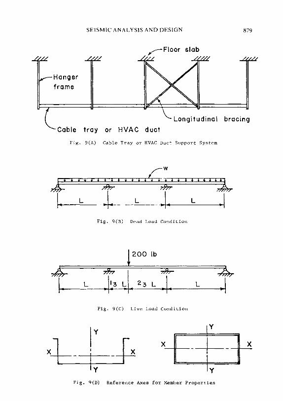
The analysis and design of cable trays, cable buses, and HVAC ducts
is very similar and therefore, only the analysis and design of cable
trays is described here. A typical cable tray support system is
~hown in Fig. 9(A). For computing forces in vertical plane, the
cable tray is assumed to be ~ontinuous over two supports as shown in
Fig. 9(B). This assumption gives results which are consistent with
the comprehensive dynamic analysis of the entire system. The forces
induced due to various loads are computed as follows:
1. Dead Load Only
Referring to Fig. 9(B), the maximum design moment will be
wL2/l0
where
w dead load per unit length of pan cable tray
L support spacing
2. Dead Load Plus Live Load
Referring to Fig. 9(B) and 9(C) maximum design moment will be
~L wL2/l0 + 0.08PL
where,
P = concentrated live load, 200 lbs. placed anywhere on the tray.
3. Safe Shutdown Earthquake (SSE)
The computations described here are based on a study of analyti-
cal models by the author of entire cable tray systems including
trays, hangers, etc. The objective of the study was to develop a
Hanger
frame
SEISMIC ANALYSIS AND DESIGN 879
,..----Floor slab
Longitudinal bracing
Cable tray or HVAC duct
J! 1-
£ 1-
Fig. 9(A) Cable Tray or HVAC Duct Support System
* * i f *%* i * f .<;£ i + + * * * %l L .\~ L ~I~ L .I
Fig. 9(B) Dead Load Condition
! 200 lb
L 7h I 7Er .. \~3 ~ • 23 L .. \. L
Fig. 9(C) Live Load Condition
y
X - -i I y
Fig. q(D) Reference Axes for Member Properties
X

880 THIRD SPECIALTY CONFERENCE
"implified approach for the design of various components of the cable
tray system. It was determined that the effect of the first mode was
more than 90% of the total dynamic response due to all significant
modes. Therefore, equivalent static analysis is performed in lieu of
dynamic analysis.
The forces caused due to dead load and seismic excitations in vertical
and horizontal directions are computed as follows:
(a) Moment due to vertical excitation:
M (wL 2
/10) v
where,
a v
a acceleration, as obtained from the response spectrum curve of the v
supporting slab for vertical component of SSE, corresponding to
the vertical period of vibration, of the cable tray.
The vertical period of vibration Tv of the rable tray for a three span
continuous beam shown in Fig. 9(B) is computed as follows:
v J WLJ = ~- ----~---
27.76 X 10⁶
xI T
X
where,
I moment of inertia of the tray about horizontal axis, (in.4
)
W wL (kips)
L = span in inches
(h) Maximum moment due to horizontal excitation in the direction
perpendicular to longitudinal axis of cable trays:
2 ~ ~ (wL /I 0) . ah
SEISMIC ANALYSIS AND DESIGN 881
where,
ah peak acceleration from the response spectrum of the supporting
slab due to horizontal component of SSE.
The peak acceleration value of ah is used due to uncertainty in
determining the period of vibration in the horizontal direction.
This is due to the fact that period is a function of relative lateral
stiffnesses of cable tray and the supporting hangers and can not be
determined by simple methods. However, the model studies indicate
that the total response in this case is primarily due to the lg mode
and therefore, the factor of 1.5 is not required.
(c) Forces due to horizontal excitation in direction parallel to the
longitudinal axis of the cable trays:
Axial stress due to horizontal excitation in the direction of the
longitudinal pan axis is very small compared to the forces caused due
to excitation in other directions. Therefore, they are not included
in the design. However, it is imperative that adequate bracing
should be provided to prevent any longitudinal motion during the
earthquake.
4. Operating Basis Earth~<l_ke __ (.OBE)
The forces induced due to OBE are computed in a similar way by sub
stituting the floor response spectra for OBE earthquake.
Stress Combination
The stresses caused due to dead load and excitation in horizontal
a11d vertical directions are combined as follows:

882 THIRD SPECIALTY CONFERENCE
0 = (M /S) +' /(M /S ) 2 + (M /S')z dL X \1 V X -n y
where design
o =;stress at the point under consideration
S section modulus about 'X' (horizontal) axis, see Fig. 9 (D) X
S' section modulus about 'Y' (vertical) axis,modified to reflect y
different allowable stresses for bending of the tray in
vertical and horizontal planes. The allowable stress for
bending in horizontal plane is considerably smaller
compared to that in the vertical plane which is used as a basis
for design.
S section modulus about 'Y' (vertical) axis y
fv allowable stress for bending in vertical plane. This stress
is different for top and for the bottom of the tray in
compression.
fh allowable stress for bending in horizontal plane
s' y
s y
The stress "o" is computed for the top of the tray to be in
compression at the center of the span and bottom of the tray to be
in compression at the continuous support. This stress is then
checked against the corresponding allowable design stress fv.
Allowable Stresses
The top flange or the lip of the cable trays is often laterally
unbraced and can buckle separately by a deflection of the compression
flange relative to the tension flange accompanied by out-of-plane
SEISMIC ANALYSIS AND DESIGN 883
bending of the web and the rest of the section. Accurate analysis
of such a situation is extremely complex. The allowable bending
stress for such cases may be determined according to Section 3 of
the Supplementary Information on AISI Specifications.
Allowable stresses in bending when the bottom flange is in
compression may be computed by determining the effective width as
per Sec. 2.3 of the Specifications. Allowable bending stress for
bending in the plane of the web may be computed as per Sec. 3.4.2 of
the Specifications.
In case of cable trays without a solid bottom or other members
where theoretical determination of properties is impossible, the
properties of sections should be determined by actual tests.
II. Surport Frames
The cable trays, cable buses, and HVAC ducts are supported by means
of various types of support frames as shown in Fig. 5. Selection
of a type of frame depends on the available support conditions,
clearances, type of connections, etc. Only trapeze type of hanger
frame shown in Fig. lO(A) are considered herein. Since the lateral
stiffness of trays or ducts is very small, the hanger frames act
independently during excitation in the horizontal direction. The
frame, therefore, could be represented by a single-degree-of-freedom
system with the mass of the trays lumped at the tray level, as shown
in Fig. lO(B). The forces induced in the trapeze frame due to
various loadsare computed as follows:

884
\ \ \ \ \ \ \ \
THIRD SPECIALTY CONFERENCE
Iv Iv
I. b
Fig. IO(A) Fig. IO(B)
Seismic Seismic Excitation
-4 ...
I I I I I I I I I \ \
l Excitoti~n
Fig. !O(C)
\ \ \ \ \ \
---~.J --- ---Fig. lO(D)
Fig. 10 - Typical Support Frame
\ I I I I I I I I
h

SEISMIC ANALYSIS AND DESIGN
1. Dead Load Only
The forces due to dead load W are calculated from simple frame
analysis. W is the reaction of the hanger from cable trays.
W = w. L
where,
w dead load of tray per linear foot
L hanger spacing, ft.
2. Forces Due to Horizontal Excitation
F =F.w.ah
where,
F forces in the frame due to unit horizontal load
ah horizontal acceleration corresponding to the horizontal
period of vibration Th computed from the response spectra
of the supporting floor slab.
considering Fig. 10(C)1 Th is given by
= 2TI !W JKi,
where,
K
T h
(\
2TI
lateral frame stiffness
deflection
l b IV + -.-.-J
2 h Ih
due to unit
3 l b IV Wl1 (l + -.-.-)
2 h Ih
load
Ih moment of inertia of horizontal member
l moment of inertia of the vertical member v
h height of the frame
885
886 THIRD SPECIALTY CONFERENCE
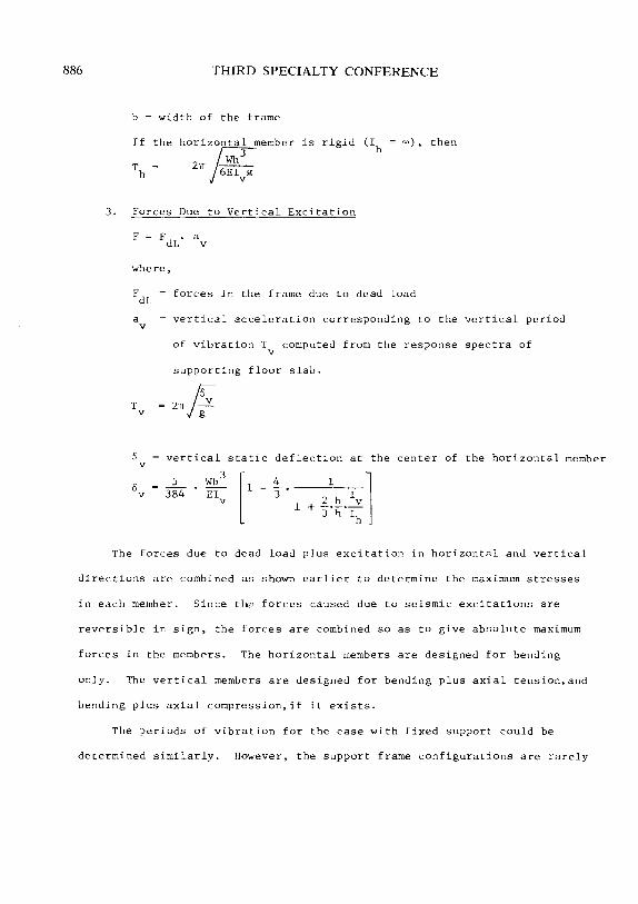
b = width of the frame
If the horiz~member
2rr j6E'Qi is rigid (Ih oo), then
3. Forces Due to Vertical Excitation
F = F dL
where,
a v
FdL forces in the frame due to dead load
av vertical acceleration corresponding to the vertical period
T v
6 v
0 v
of vibration Tv computed from the response spectra of
supporting floor slab.
2rr /i-vertical static deflection at the center of the horizontal member
5 Wb3
[ 1 -4
~~t. 1v l 384 EI 3. v
1 + 3 IJ. Ih
The forces due to dead load plus excitation in horizontal and vertical
directions are combined as shown earlier to determine the maximum stresses
in each member. Since th?• forces caused due to seismic excitations are
reversible in sign, the forces are combined so as to give absolute maximum
forces in the members. The horizontal members are designed for bending
only. The vertical members are designed for bending plus axial tension,and
bending plus axial compression,if it exists.
The periods of vibration for the case with fixed support could be
determined similarly. However, the support frame configurations are rarely

SEISMIC ANALYSIS AND DESIGN 887
simple as mentioned above. Most frames have multilevel trays and are
provided with diagonal bracing. A complete dynamic analysis of such
frames is required to compute the forces induced due to earthquake
motions.
SYNOPSIS
The use of cold-formed steel structural members in nuclear power
plants is discussed. A design criteria for a seismic resistant design
of such members is presented. Simplified methods of seismic analysis
are illustrated. However, the design information provided by the
manufacturers is not adequate for complete dynamic analysis and more
research should be undertaken to provide it.

888 THIRD SPECIALTY CONFERENCE
APPENDIX I - DEFINITIONS
Operating Basis Earthquake (OBE): The earthquake which produces the
vibratory ground motion for which structures, systems, and components,
necessary for power generation and safety of the plant, are designed to
perform their intended function. This earthquake is usually assumed to
be equivalent of the 50 percent of the Safe Shutdown Earthquake. OBE
could occur several times at the site during the life of the plant.
Response Spectrum: A plot of the maximum response (acceleration, velo
city, or displacement) of a family of idealized single-degree-freedom
damped oscillators as a function of natural frequencies (or periods) of
the oscillators to a specified vibratory motion input at their support.
Safe Shutdown Earthquake (SSE): The earthquake which produces the maxi
mum vibratory ground motion that the nuclear power plant is designed to
withstand without functional impairment of those compone11ts 11ecessary to
shut down the reactor and maintain the plant in safe condition. This
earthquake is expected to be the largest earthquake which could occur at
the site during the life of the plant.
Seismic Category I Components: Those structural components which are
essential to the safe shutdown and control of the reactor if earthquake
occurs. These components must perform their intended function during
and after the earthquake.

a v
b
E
SEISMIC ANALYSIS AND DESIGN 889
APPENDIX II - NOTATION
vertical acceleration
horizontal acceleration
width of the support frame
modulus of elasticity
F forces in support frame due to horizontal excitation
F forces in support frame due to unit horizontal load
FdL forces in support frame due to dead load
f v
g
h
l v
l X
K
L
M v
p
s X
s y
allowable stress in cable tray for bending in horizontal plane
allowable stress in cable tray for bending in vertical plane
acceleration due to gravity
height of the support frame
moment of inertia of horizontal member of support frame
moment of inertia of vertical member of support frame
moment of inertia of cable tray about horizontal axis
lateral frame stiffness
cable tray support spacing
moment in cable tray due to dead load only
moment in cable tray due to horizontal excitation
moment in cable tray due to dead load plus live load
moment in cable tray due to vertical excitation
concentrated live load
section modulus of cable tray about 'X' (horizontal) axis
section modulus of cable tray about 'Y' (vertical) axis

890
s' y
v
w
CJ
CJ X
0 y
0 z
6 v
THIRD SPECIALTY CONFERENCE
modified section modulus of cable tray about 'Y' (vertical) axis
horizontal period of vibration
vertical period of vibration
total load over length 'L' of the cable tray
dead load per unit length of cable tray or HVAC duct
design stress
stresses due to dead load only
stresses due horizontal earthquake motion in 'X' direction
stresses due horizontal earthquake motion in 'Y' direction
stresses due to vertical earthquake motion
lateral deflection of support frame due to unit load
vertical static deflection at the center of the horizontal member of the support frame
SEISMIC ANALYSIS AND DESIGN
APPENDIX III - REFERENCES
1. IEEE Std. 344-1971, "IEEE Guide for Seismic Qualification of Class I Electric Equipment for Nuclear Power Generating Stations", Institute of Electrical and Electronics Engineers, Inc.
891
2. M. Stoykovich, "Seismic Design and Analysis of Nuclear Power Plant Components", Specialty Conference on Structural Design of Nuclear Power Plants, Dec. 17-18, 1973, Chicago.
3. Timoshenko, S.P., and Young, D.H., Vibration Problems in Engineering, 3rd Edition, D. Van Nostrand Co., New York, 1955.
4. USAEC, Dictorate of Regulatory Standards, Regulatory Guide 1.61, "Damping Values for Seismic Design of Nuclear Power Plants", Oct. 1973.
5. USAEC, Dictorate of Licensing, Regulatory Standard Review Plan, Sec. 3.8, "Design of Seismic Category I Structures".