cold formed steel beams under monotonic and cyclic loading: experimental investigation
TRANSCRIPT
Journal of Constructional Steel Research 65 (2009) 219–227
Contents lists available at ScienceDirect
Journal of Constructional Steel Research
journal homepage: www.elsevier.com/locate/jcsr
Cold formed steel beams under monotonic and cyclic loading:Experimental investigationB. Calderoni a,∗, A. De Martino b, A. Formisano a, L. Fiorino aa Department of Structural Engineering, University of Naples ‘‘Federico II’’, P.le Tecchio 80, 80125 Naples, Italyb Department of Constructions and Mathematical Methods in Architecture, University of Naples ‘‘Federico II’’, Via Monteoliveto, 80134 Naples, Italy
a r t i c l e i n f o
Article history:Received 20 December 2006Accepted 2 July 2008
Keywords:Cyclic loadingCold-formed profilesCoupled channel beamsExperimental testsMonotonic loadingThin-walled profiles
a b s t r a c t
The use of cold-formed thin-walled steel profiles in seismic structures is nowadays strongly penalizedby code prescriptions, which impose for this kind of members a q-factor equal to 1, so that the designfor the action of a severe earthquake must be carried out practically in the elastic field. On the otherhand, some theoretical studies on the seismic performance of such structural systems gave encouragingresults. For these reasons, an experimental and theoretical research program on the behaviour of cold-formed members loaded by cyclic loads has been started in the recent past by the authors. In the firstphase of the experimental program, tests in bending on coupled channel beams under monotonic andcyclic load have been carried out. In this paper the research program is described, the obtained resultsare presented and some preliminary consideration is made on the behaviour of these types of members.
© 2008 Elsevier Ltd. All rights reserved.
1. Introduction
The use of steel structures, built up by light gauge steelmembers, should be very important from the point of view ofboth research and technology, particularly for a country like Italy,which is producer of this kind of profiles and has a large number ofdeteriorated buildings to be restored and protected against seismicactions.The practical use of steel moment resisting frame made of
cold-formed sections in seismic zones is slowly increasing andthe attention of scientific community is mainly focused on thedefinition of reliable q-factors, considering that the seismic codesdo not allow at the moment a seismic design with a significantreduction of elastic seismic actions.It seems particularly interesting to deep the seismic capacity
of cold-formed steel structures, which is directly related to thedefinition of failure criteria for members and connections. Withreference to this point, considering that steel structures areallowed to undergo significant inelastic deformations under severeearthquakes, seismic capacity is often governed by the maximumallowable deformation (plastic rotation) rather than by strengthcapacity of the connections themselves.In the general field of energy dissipation and structural damage,
the application of light gauge steel members is strongly penalisedon the base of their lack in dissipation capacity, which does notallow a favourable behaviour in case of seismic events.
∗ Corresponding author. Tel.: +39 0817682440; fax: +39 0815934792.E-mail addresses: [email protected] (B. Calderoni), [email protected]
(A. De Martino), [email protected] (A. Formisano), [email protected] (L. Fiorino).
0143-974X/$ – see front matter© 2008 Elsevier Ltd. All rights reserved.doi:10.1016/j.jcsr.2008.07.014
On the other side, studies on light steel gauge portal frames,carried on in the past by Japanese [23] and Italian [3] researchers,showed an acceptable performance under cyclic actions corre-sponding to moderate earthquakes. While the elastic behaviour ofthis type of structures or members has been deeply analysed, theirpost elastic behaviour, the technology and the elastic and post elas-tic behaviour of connections deserve more studies.So, it is necessary to analyse the behaviour of member to define
clearly the parameters influencing the problem. Particularly, itneeds to take into account the cyclic nature of the action and thedegrading phenomena in terms of strength, stiffness and rotationalcapacity.Recent researches, based on simplified assumptions about the
cyclic degrading behaviour as resulting from experimental datagiven by some authors, allowed the modelling of a simple portalframe behaviour which, under the action of several earthquakes,showed the possibility of using light gauge member frames in lowseismic areas with q-factor varying from 2 to 3, if they show a notnegligible ‘‘ductility’’ (µ ∼= 3) [4,5].It is worth noticing that moment resisting frame with cold-
formed steel members have been not deeply studied in recentyears, except for the case of storage racking systems. Nevertheless,this type of structures could be not comparable with frameswithstanding seismic actions and usually used in the buildings. Onthe contrary, buildingsmade of cold-formed steel frames sheathedwith panels have been largely studied in Europe [21,8,15–17,12,13,19], North America [25,24,22,2,1], Japan [20] and Australia [18].But also in this type of structures the structural response underhorizontal actions generally depends on the interaction between

220 B. Calderoni et al. / Journal of Constructional Steel Research 65 (2009) 219–227
Fig. 1. Nominal geometry of specimens (front view and transversal sections).
profiles, sheathing panels and sheathing fasteners and then theseismic capacity is not directly related to the plastic behaviour ofcold-formed steel profiles.The experimental activity presented in this paper is aimed to
evaluate the performance of a double channel profile from thepoint of view of deformation capacity and cyclic degradation. Theinterest on such profiles is dictated from the fact that they couldbe used, for example, as beams in moment resisting steel frameshaving columns made of hot rolled compact sections.
2. The experimental programme and the equipment set-up
The experimental investigation has been performed on someof identical beam specimens. A preliminary test was carried outon a slightly different beam, in order to test the efficiency ofthe experimental equipment and set-up. More in detail, twomonotonic tests, on the beamsnamedT01 and T02, and three cyclictests, on the beams named T03, T04, and T05, have been carriedout. In the preliminary test (beam named T00) a mixed (cyclic andmonotonic) load history was applied to the beam.The generic specimen ismade of 1740mm long double back-to-
back coupled cold formed unlipped channel profiles. In particular,the two C-section beams are linked together by a 20 mm thickvertical inner plate placed at mid-length. Two 15 mm thick endplates are welded to the members at both edges of the beamallowing for the connection to the external restraints. Moreover,the profiles are stiffened by means of 4 mm thick vertical platesparallel to the web and welded to the flanges at mid-length,corresponding to the load application zone; further four horizontal4 mm thick batten plates have been welded to the top and bottomflanges too. The geometrical scheme of the specimen is given inFig. 1, in which the front view and some significant transversalsections are shown.Considering the single channel profile, the geometrical slender-
ness b/t (wide to thickness ratio) for flange and web are 10.5 and61.7, respectively. Consequently, according to the Eurocode 3 [11],the profile can be classified in class 4 for the flange and class 2 forthe web, so that the whole section should be classified as a slendersection (class 4).With reference to the material, the average yield and ultimate
stresses of the used steel are fy = 364 MPa and fu = 425 MPa,respectively. These values have been obtained from tensile testspecifically performed.The beams used in the preliminary test has a different
transversal section, obtained by connecting back to back twolipped channel profiles, having stiffeners (20 mm long) at the edgeof the flanges, as depicted in Fig. 2. This arrangement has beenchosen for allowing some comparison with the results of testsdeveloped in the past by other researchers [10].All tests were carried out on simply supported beam, loaded by
a singlemid-span concentrated force (three-point bending test), as
Fig. 2. Specimen used in the first test.
(a) Test configuration for monotonic tests.
(b) Test configuration for cyclic tests.
Fig. 3. Global view of the specimens T01 and T05 ready for testing.
shown in Fig. 3. In particular the beam was restrained by a hingeon the left side and a simple support on the other side. Lateralbracing system was adopted in the cyclic test in order to avoidflexural–torsional buckling.Deflections and deformations were measured during testing
by means of displacement transducers (LVDT) and strain gauges,respectively. In particular, a pair of LVDTs (1 and 2) has been usedto measure the horizontal displacement of the simple support anda further pair (3 and 4) to acquire the rotation of the edge hinge.For the specimen T03, T04 and T05 a further LVTD (5) has beenused tomeasure the vertical displacement at mid length. The LVDTlocations are shown in Fig. 4(a) and (b).Concerning the strain gauges, two different arrangements were
adopted. In particular, for the specimens T01, T02 and T03, onestrain gauge has been placed on both top and bottom flanges ofeach profile in four significant sections. For the specimens T04 andT05 only the bottom flange of a single profile has been monitored.In these cases four strain gauges have been positioned on eachtop and bottom sides in two significant sections. The strain gaugelocations are shown in Fig. 4(c) and (d).

B. Calderoni et al. / Journal of Constructional Steel Research 65 (2009) 219–227 221
(a) Arrangement type 1 (specimens T00, T01 and T02). (b) Arrangement type 2 (specimens T03, T04 and T05).
(c) Arrangement type 1 (specimens T00, T01, T02, T03). (d) Arrangement type 2 (specimens T04 and T05).
Fig. 4. LVDTs and strain gauges location.
The tests were carried out at the Department of StructuralEngineering of the University of Naples Federico II, using testingequipment consisting of a reaction steel frame and a 500 kNhydraulic jack. The loading jack was controlled by means of anelectronic device, which have been used for data acquisition too.All tests were carried out in displacement control, using a lowdisplacement rate for the sake of obtaining a quasi-static loadingprocedure [14].In the preliminary test (T00) two complete cycles (loading and
unloading phases) were carried out, in which mid-span deflectionranged from 0 mm to 10 mm and from 0 mm to 20 mm in the firstand in the second cycle, respectively. Then a monotonic loadingphasewas performed up to deflection equal to 80mm, followed byan unloading phase, in which the beamwas pushed up to a reversedisplacement of 80 mm.For tests T01 and T02 a monotonic test protocol has been
adopted, it being characterised by displacements applied withrate of 0.5 mm/s. The increasing displacement step was 10 mm,followed by a hold step of 20 s.In the test T01 the displacement has been progressively
increased up to the complete collapse, reached at 120 mm, whilein test T02 the maximum displacement has been fixed at 20 mm,in order to investigate also the response in the unloading phaseimmediately after the attainment of local buckling.Cyclic tests have been carried out using a procedure based on
indications given in [9]. A fixed constant displacement amplitudehas been adopted and the number of cycles has not beeninitially defined: the test ended when the failure occurred. Thedisplacement amplitudes were 15 mm, 30 mm and 45 mm for testT03, T04 and T05, respectively. In cyclic tests the displacement ratehas been fixed at 1.0 mm/s and each cycle has been followed by ahold step of 20 s.In the following paragraph each test is described in detail,
reporting the corresponding more significant results.
3. Test description and results
The performed tests have been reported by means of thecorresponding reaction force — applied deflection (F–δ) diagram,
Fig. 5. T00 specimen employed in the first test.
Fig. 6. F–δ curve for test T00.
in which some points have been highlighted, so defining a seriesof meaningful phases. For each phase a brief description of theoccurred phenomena is given, also by means of significant photos.
3.1. Preliminary test (beam T00)
In Fig. 5 the beam T00 before testing is shown and in Fig. 6 theexperimental F–δ curve is depicted.
222 B. Calderoni et al. / Journal of Constructional Steel Research 65 (2009) 219–227
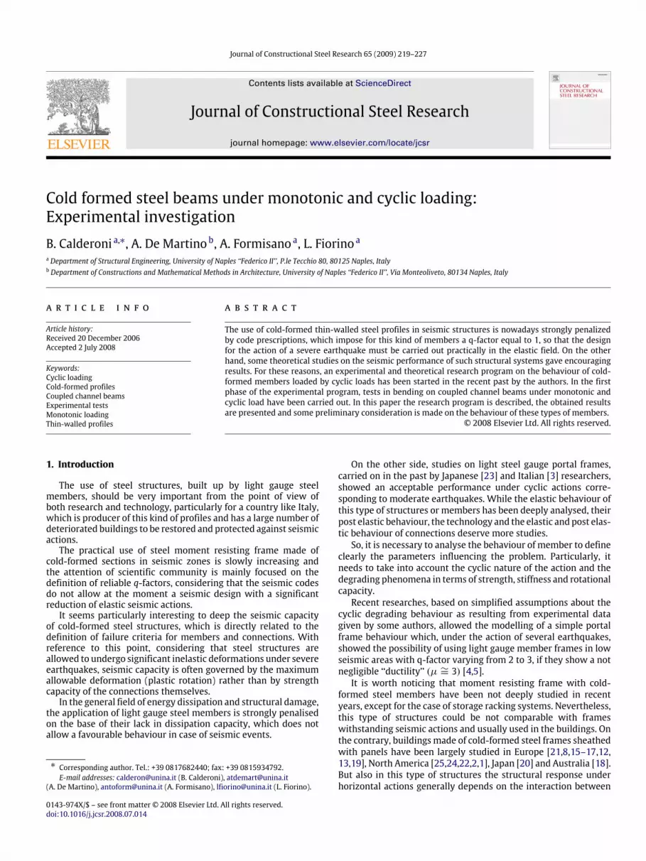
Fig. 7. Starting (a) and development (b) of local buckling in the bottom flange of the T00 beam.
(a) The deformed specimen. (b) Zoom.
Fig. 8. Test T00: Distorted configuration for downward deflection.
The first phase (0-A) corresponds to the first loading cycle, inwhich the beam has been pulled up to 10 mm by means of a loadof 55 kN and subsequently pushed down to the initial position. Thebehaviour was practically linear-elastic, but some slipping due totesting equipment can be observed, particularly in the pulling upbranch, so that the reaction force for a null displacement was notnull (but equal to 30 kN).In the second phase (A–B) a new complete cycle has been
performed: The beam has been pulled up to 20 mm, reaching a85 kN reaction force, and thenmoved down to a null displacement.Again some little slipping occurred; moreover a non-linearbehaviour was exhibited by the specimen for an applied load ofabout 75 kN, so denoting the attainment of first yielding in thesection before the occurrence of local instability. For these reasonsin the unloading phase a residual deflection (roughly 10 mm) wasshowed for a null acting force.The third phase (B–C–D) has been a monotonic pulling up
step, in which a maximum deflection of 80 mm was reached. Fora displacement equal to 25 mm local buckling occurred in thebottom flange (Fig. 7), giving rise to a softening branch in thediagram. The maximum corresponding reaction force was 90 kN(point C),which represents the ultimate load bearable by the beam.The local deformation (wave amplitude) was roughly 10 mm.When continuing to pull up the beam, the reaction force decreasedto 40 kN for a deflection of 80 mm (point D).During development of the softening branch, local buckling
interested a larger zone of the flange and the web too, with notsymmetric pattern of deformation with respect to the verticalcentral axis of the beam. At the maximum displacement the beamshowed a very strong deformation in the bottom buckled zone.When the specimenhas beenunloaded, a very large residual plasticdeflection was exhibited for a null reaction force.
In the subsequent reversal loading phase (fourth phase D′–E)a significant reduction in stiffness was observed while the localdeformation was going to be recovered. Local buckling alsooccurred in the top flange for a deflection of 10 mm.Then a new softening branch (E–F) in the reversal side of
the F–δ diagram appeared and the test continued up to thedownward deflection of 80 mm, characterized by a very strongdeformation also in the top flange and in the web (Fig. 8). Aresidual reaction force of only 30 kNwasmeasuredwhen the globalflexural–torsional buckling of the beam occurred, caused by thevery distorted configuration of the specimen.When unloaded and removed from the loading frame, the beam
recovered only a little bit of the total deflection.
3.2. Monotonic test — beam T01
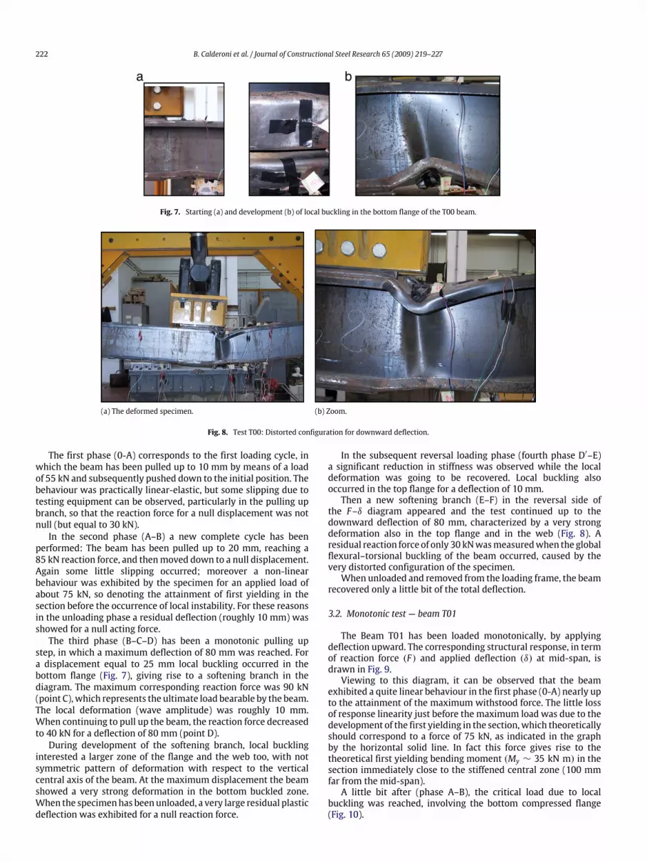
The Beam T01 has been loaded monotonically, by applyingdeflection upward. The corresponding structural response, in termof reaction force (F) and applied deflection (δ) at mid-span, isdrawn in Fig. 9.Viewing to this diagram, it can be observed that the beam
exhibited a quite linear behaviour in the first phase (0-A) nearly upto the attainment of the maximum withstood force. The little lossof response linearity just before the maximum load was due to thedevelopment of the first yielding in the section,which theoreticallyshould correspond to a force of 75 kN, as indicated in the graphby the horizontal solid line. In fact this force gives rise to thetheoretical first yielding bending moment (My ∼ 35 kN m) in thesection immediately close to the stiffened central zone (100 mmfar from the mid-span).A little bit after (phase A–B), the critical load due to local
buckling was reached, involving the bottom compressed flange(Fig. 10).
B. Calderoni et al. / Journal of Constructional Steel Research 65 (2009) 219–227 223
Fig. 9. F–δ curve for test T01.
Fig. 10. Test T01: The buckled bottom flange.
Increasing the applied deflection, local buckling progressivelyincreased and involved the web too, as shown in Fig. 11. Thehalf-wave length of local deformation was about 60 mm withdisplacements toward the internal of the profile. The value of themaximum load recorded during the test was Fmax = 77.6 kNwhendisplacement was equal to 16.2 mm.Once this deflection has been exceeded, the specimen expe-
rienced an unstable decreasing behaviour (phase B–C) up to thecollapse. The collapse displacement can be considered equal to80 mm. In fact at this value of deflection the deformed flanges ofthe profiles went in contact with the central stiffening plates of thespecimen, as shown in Fig. 12. For this reason, further increasing ofthe deflection led to growing of reaction force and stiffening of thebeam (phase C–D) up to 120mm,when the loading phase has beenstopped, considering that the results obtained in this phasewas notsufficiently reliable.The minimum registered reaction force is roughly 30 kN (point
C), which can be considered as the residual bearing capacity ofthe specimen. Subsequently, the beam has been unloaded (phaseD–D′), showing a very significant residual deflection, equal toabout 105 mm, for a null reaction force. When the beam wasadditionally pushed down (phase D′–E), a significant reduction inboth stiffness and resistance was noted and the local deformationin the previous compressed flanges was going to be partiallyrecovered.Further pushing the beam, local buckling occurred also in
the top flanges just a little after the beam reached the originalhorizontal position (δ = 0 mm) (Fig. 13).The test ended at the occurrence of the global flexural–torsional
instability for a downward deflection of 29 mm.
3.3. Monotonic test — beam T02
As already said, beam T02 had the same initial configurationthan beam T01, but it has been pushed up to only 20 mm, in
Fig. 11. Test T01: Local buckling also in the web.
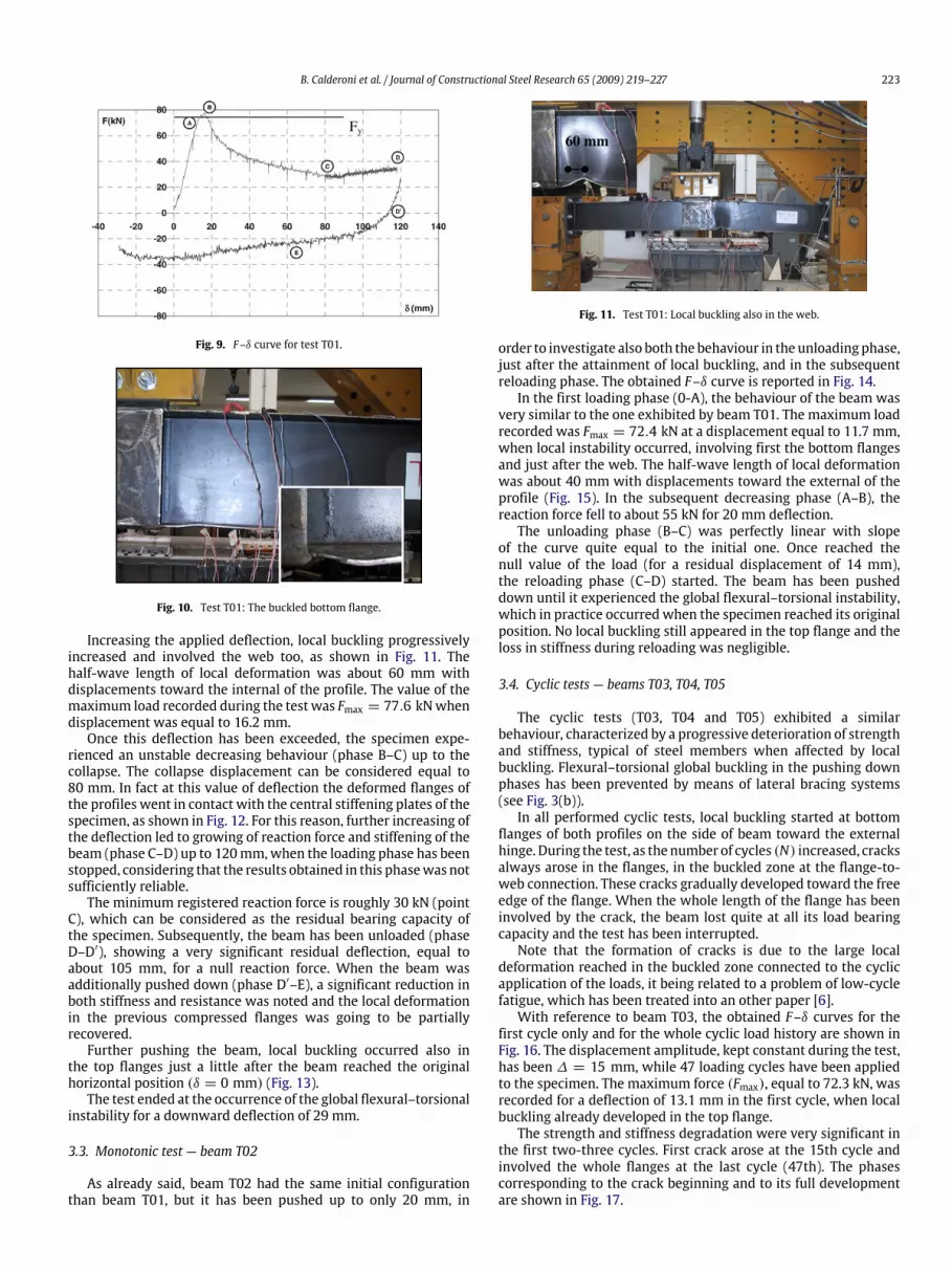
order to investigate also both the behaviour in the unloading phase,just after the attainment of local buckling, and in the subsequentreloading phase. The obtained F–δ curve is reported in Fig. 14.In the first loading phase (0-A), the behaviour of the beam was
very similar to the one exhibited by beam T01. The maximum loadrecorded was Fmax = 72.4 kN at a displacement equal to 11.7 mm,when local instability occurred, involving first the bottom flangesand just after the web. The half-wave length of local deformationwas about 40 mm with displacements toward the external of theprofile (Fig. 15). In the subsequent decreasing phase (A–B), thereaction force fell to about 55 kN for 20 mm deflection.The unloading phase (B–C) was perfectly linear with slope
of the curve quite equal to the initial one. Once reached thenull value of the load (for a residual displacement of 14 mm),the reloading phase (C–D) started. The beam has been pusheddown until it experienced the global flexural–torsional instability,which in practice occurred when the specimen reached its originalposition. No local buckling still appeared in the top flange and theloss in stiffness during reloading was negligible.
3.4. Cyclic tests — beams T03, T04, T05
The cyclic tests (T03, T04 and T05) exhibited a similarbehaviour, characterized by a progressive deterioration of strengthand stiffness, typical of steel members when affected by localbuckling. Flexural–torsional global buckling in the pushing downphases has been prevented by means of lateral bracing systems(see Fig. 3(b)).In all performed cyclic tests, local buckling started at bottom
flanges of both profiles on the side of beam toward the externalhinge. During the test, as the number of cycles (N) increased, cracksalways arose in the flanges, in the buckled zone at the flange-to-web connection. These cracks gradually developed toward the freeedge of the flange. When the whole length of the flange has beeninvolved by the crack, the beam lost quite at all its load bearingcapacity and the test has been interrupted.Note that the formation of cracks is due to the large local
deformation reached in the buckled zone connected to the cyclicapplication of the loads, it being related to a problem of low-cyclefatigue, which has been treated into an other paper [6].With reference to beam T03, the obtained F–δ curves for the
first cycle only and for the whole cyclic load history are shown inFig. 16. The displacement amplitude, kept constant during the test,has been ∆ = 15 mm, while 47 loading cycles have been appliedto the specimen. The maximum force (Fmax), equal to 72.3 kN, wasrecorded for a deflection of 13.1 mm in the first cycle, when localbuckling already developed in the top flange.The strength and stiffness degradation were very significant in
the first two-three cycles. First crack arose at the 15th cycle andinvolved the whole flanges at the last cycle (47th). The phasescorresponding to the crack beginning and to its full developmentare shown in Fig. 17.
224 B. Calderoni et al. / Journal of Constructional Steel Research 65 (2009) 219–227
(a) Front view. (b) Zoom (back side).
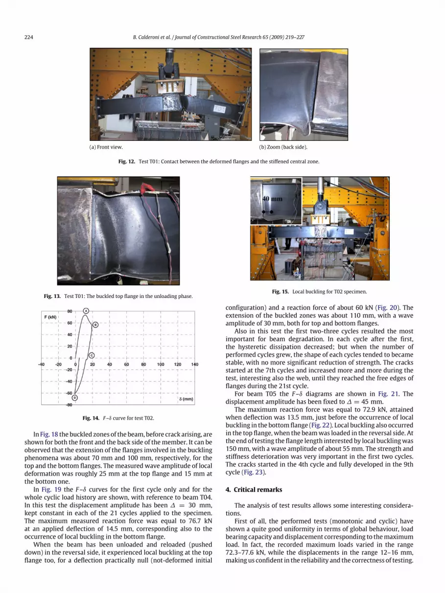
Fig. 12. Test T01: Contact between the deformed flanges and the stiffened central zone.
Fig. 13. Test T01: The buckled top flange in the unloading phase.
Fig. 14. F–δ curve for test T02.
In Fig. 18 the buckled zones of the beam, before crack arising, areshown for both the front and the back side of themember. It can beobserved that the extension of the flanges involved in the bucklingphenomena was about 70 mm and 100 mm, respectively, for thetop and the bottom flanges. Themeasured wave amplitude of localdeformation was roughly 25 mm at the top flange and 15 mm atthe bottom one.In Fig. 19 the F–δ curves for the first cycle only and for the
whole cyclic load history are shown, with reference to beam T04.In this test the displacement amplitude has been ∆ = 30 mm,kept constant in each of the 21 cycles applied to the specimen.The maximum measured reaction force was equal to 76.7 kNat an applied deflection of 14.5 mm, corresponding also to theoccurrence of local buckling in the bottom flange.When the beam has been unloaded and reloaded (pushed
down) in the reversal side, it experienced local buckling at the topflange too, for a deflection practically null (not-deformed initial
Fig. 15. Local buckling for T02 specimen.
configuration) and a reaction force of about 60 kN (Fig. 20). Theextension of the buckled zones was about 110 mm, with a waveamplitude of 30 mm, both for top and bottom flanges.Also in this test the first two-three cycles resulted the most
important for beam degradation. In each cycle after the first,the hysteretic dissipation decreased; but when the number ofperformed cycles grew, the shape of each cycles tended to becamestable, with no more significant reduction of strength. The cracksstarted at the 7th cycles and increased more and more during thetest, interesting also the web, until they reached the free edges offlanges during the 21st cycle.For beam T05 the F–δ diagrams are shown in Fig. 21. The
displacement amplitude has been fixed to∆ = 45 mm.The maximum reaction force was equal to 72.9 kN, attained
when deflection was 13.5 mm, just before the occurrence of localbuckling in the bottom flange (Fig. 22). Local buckling also occurredin the top flange, when the beamwas loaded in the reversal side. Atthe end of testing the flange length interested by local bucklingwas150mm, with a wave amplitude of about 55mm. The strength andstiffness deterioration was very important in the first two cycles.The cracks started in the 4th cycle and fully developed in the 9thcycle (Fig. 23).
4. Critical remarks
The analysis of test results allows some interesting considera-tions.First of all, the performed tests (monotonic and cyclic) have
shown a quite good uniformity in terms of global behaviour, loadbearing capacity anddisplacement corresponding to themaximumload. In fact, the recorded maximum loads varied in the range72.3–77.6 kN, while the displacements in the range 12–16 mm,making us confident in the reliability and the correctness of testing.

B. Calderoni et al. / Journal of Constructional Steel Research 65 (2009) 219–227 225
(a) First cycle. (b) Complete curve.
Fig. 16. F–δ curve for test T03.
(a) Start of the crack. (b) Full development of the crack.
Fig. 17. Test T03: Typical propagation of the crack.
(a) Buckled zone of the beam (front view). (b) Buckled zone of the beam (back side).
Fig. 18. Local buckling in T03 beam.
(a) First cycle. (b) Complete curve.
Fig. 19. F–δ curve for test T04.
226 B. Calderoni et al. / Journal of Constructional Steel Research 65 (2009) 219–227
Fig. 20. Deformed shape of T04 beam in the reloading phase.
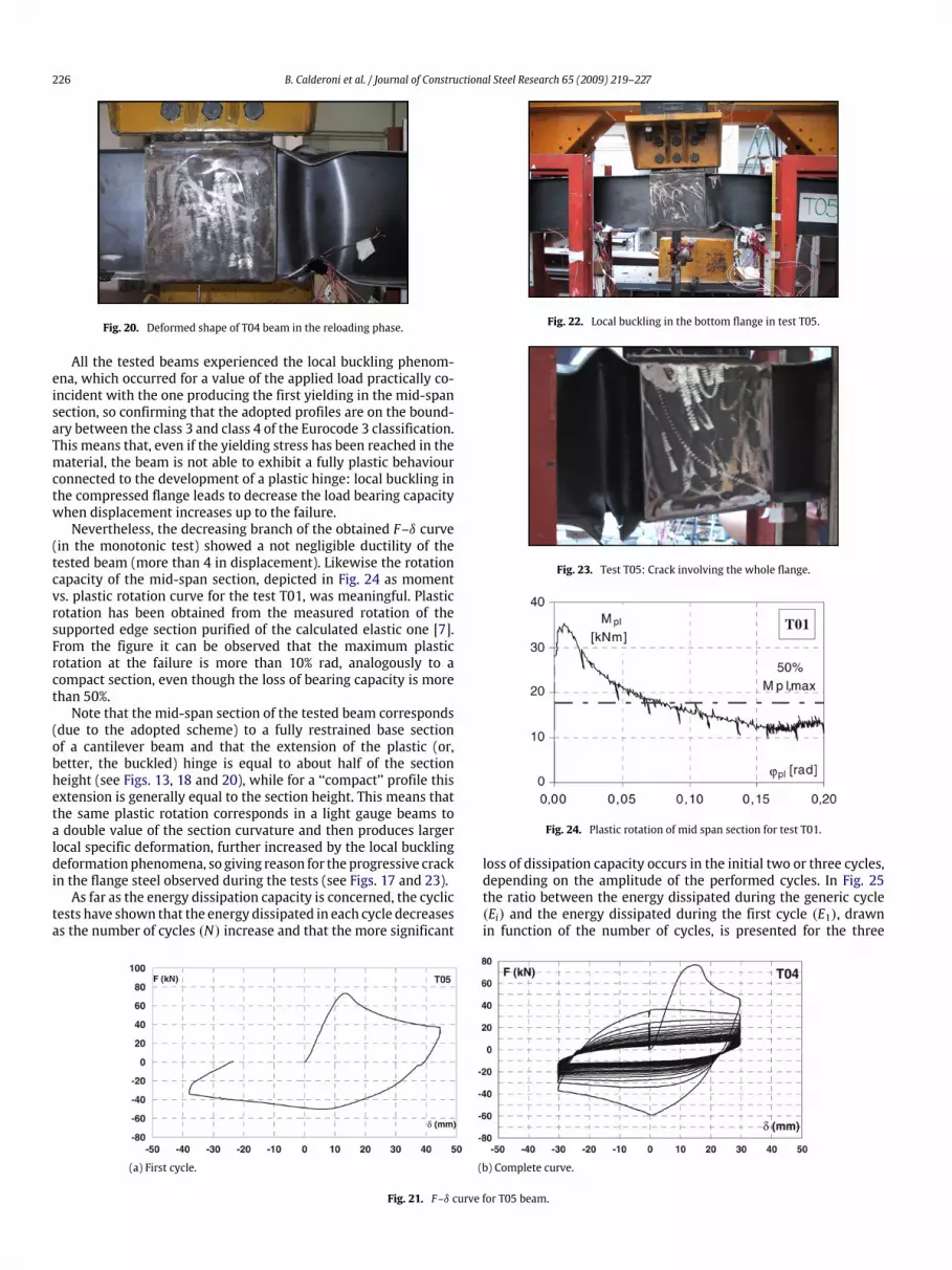
All the tested beams experienced the local buckling phenom-ena, which occurred for a value of the applied load practically co-incident with the one producing the first yielding in the mid-spansection, so confirming that the adopted profiles are on the bound-ary between the class 3 and class 4 of the Eurocode 3 classification.This means that, even if the yielding stress has been reached in thematerial, the beam is not able to exhibit a fully plastic behaviourconnected to the development of a plastic hinge: local buckling inthe compressed flange leads to decrease the load bearing capacitywhen displacement increases up to the failure.Nevertheless, the decreasing branch of the obtained F–δ curve
(in the monotonic test) showed a not negligible ductility of thetested beam (more than 4 in displacement). Likewise the rotationcapacity of the mid-span section, depicted in Fig. 24 as momentvs. plastic rotation curve for the test T01, was meaningful. Plasticrotation has been obtained from the measured rotation of thesupported edge section purified of the calculated elastic one [7].From the figure it can be observed that the maximum plasticrotation at the failure is more than 10% rad, analogously to acompact section, even though the loss of bearing capacity is morethan 50%.Note that the mid-span section of the tested beam corresponds
(due to the adopted scheme) to a fully restrained base sectionof a cantilever beam and that the extension of the plastic (or,better, the buckled) hinge is equal to about half of the sectionheight (see Figs. 13, 18 and 20), while for a ‘‘compact’’ profile thisextension is generally equal to the section height. This means thatthe same plastic rotation corresponds in a light gauge beams toa double value of the section curvature and then produces largerlocal specific deformation, further increased by the local bucklingdeformationphenomena, so giving reason for the progressive crackin the flange steel observed during the tests (see Figs. 17 and 23).As far as the energy dissipation capacity is concerned, the cyclic
tests have shown that the energy dissipated in each cycle decreasesas the number of cycles (N) increase and that the more significant
Fig. 22. Local buckling in the bottom flange in test T05.
Fig. 23. Test T05: Crack involving the whole flange.
Fig. 24. Plastic rotation of mid span section for test T01.
loss of dissipation capacity occurs in the initial two or three cycles,depending on the amplitude of the performed cycles. In Fig. 25the ratio between the energy dissipated during the generic cycle(Ei) and the energy dissipated during the first cycle (E1), drawnin function of the number of cycles, is presented for the three
(a) First cycle. (b) Complete curve.
Fig. 21. F–δ curve for T05 beam.

B. Calderoni et al. / Journal of Constructional Steel Research 65 (2009) 219–227 227
Fig. 25. Ratio Ei/E1 vs. Cycle number (N).
performed cyclic tests. It can be clearly observed that the increaseof the displacement amplitude applied during the test produces amore significant reduction of structural dissipation as the numberof cycles grows.Furthermore, the dissipated energy becomes practically con-
stant (equally to about 20% of that dissipated in the first cycle),independently of the amplitude of the cycle, when the number ofcycles becomes high and the beam is close to the failure condition.Anyway the ‘‘shape’’ of each cycle in the response F–δ diagram canbe considered satisfactory, due to the absence of negative phenom-ena as, for instance, pinching.
5. Conclusions
The monotonic and cyclic tests carried out on channel beamsmade with cold formed light gauge sections have confirmed theinfluence of local buckling phenomena on the behaviour of thiskind of structures. In fact, a significant reduction in resistance hasbeen exhibited by the specimens after attainment of local bucklingin the compressed flange and progressive loss of both load bearingcapacity and flexural stiffness have been highlighted during cyclictests.Nevertheless, the experimental results, which has to be
considered as basic data for future research developments, haveshown not negligible available ductility and energy dissipationcapacity, which could be considered in a ‘‘not elastic’’ seismicdesign of light gauge steel frames, at now not allowed by thecurrent seismic codes.Future developments of this research have already been
defined: cyclic tests with variable displacement amplitude will becarried out and the effects of axial load on themonotonic and cyclicbehaviour will be also analysed.In the meantime, a numerical model for cyclic behaviour of
such types of profiles is under definition. This model will takeinto account also the progressive deterioration of the mechanicalresponse, by means of simple rules and on the basis of only fewexperimental parameters, and could be used for better analyse alsothe dynamic behaviour of frames made of cold-formed elements.
References
[1] Boudreault FA, Blais C, Rogers CA. Seismic force modification factors for light-gauge steel-frame – wood structural panel shear walls. Can J Civ Eng 2007;34:56–65.
[2] Brantson AE, Boudreault FA, Chen CY, Rogers CA. Light-gauge steel-frame –wood structural panel shear wall design method. Can J Civ Eng 2006;33:872–89.
[3] Calderoni B, De Martino A, Ghersi A, Landolfo R. On the seismic resistance oflight gauge steel frames. In: Mazzolani FM, Gioncu V, editors. Proceedings ofSTESSA’94. Timisoara, London: E&F SPON; 1994. p. 333–43.
[4] Calderoni B, De Martino A, Landolfo R. Seismic behaviour of light gaugesimple frames: Influence of serviceability limitation and q-factor assessment.In: Costruzioni metalliche, vol. 2. Milano: ACS-ACAI Servizi Srl; 1999.
[5] Calderoni B, De Martino A. Sulla progettazione di strutture intelaiate in paretesottile in zona sismica. In: Proceedings of the XVI C.T.A. congress. 2001 [inItalian].
[6] Calderoni B, Formisano A, De Martino A. Structural behaviour and low-cyclicfatigue of cold-formed steel member under cyclic loads. In: Proceedings of thefourth international conference on coupled instabilities in metal structures.2004. p. 565–78.
[7] Calderoni B, Giubileo C, De Martino A. Assessment of hysteretic cyclicbehaviour of plastic hinge in cold-formed steel beams. In: Proceedings of thefifth international conference on behaviour of steel structures in seismic areas.2006. p. 185–90.
[8] Della Corte G, Fiorino L, Landolfo R. Seismic behavior of sheathed cold-formedstructures: Numerical study. J Struct Eng 2006;132(4):558–69.
[9] De Martino A, Manfredi G. Experimental testing procedures for the analysisof the cyclic behaviour of structural elements: Activity of Rilem technicalcommittee 134 MJP. In: Proc. of the workshop on cyclic damage andpseudodynamic tests. 1994.
[10] De Martino A, De Martino FP, Ghersi A, Mazzolani FM. Il comportamentoflessionale dei profili sottili sagomati a freddo: indagine sperimentale. Acciaio,December 1990 [in Italian].
[11] EN 1993-1-1. Eurocode 3: Design of steel structures — Part 1.1: General rulesand rules for buildings. 2005.
[12] Fiorino L, Landolfo R, Della Corte G. Lateral response of sheathed cold-formed shear walls: An analytical approach. In: Proc. of the 18th internationalspecialty conf. on cold-formed steel structures. 2006.
[13] Fiorino L, Della Corte G, Landolfo R. Experimental tests on typical screwconnections for cold-formed steel housing. Eng Struct 2007;29(8):1761–73.
[14] Formisano A. Analisi teorico-sperimentale della fatica oligociclica di travi diacciaio in parete sottile. Thesis of Degree, University of Naples Federico II,Faculty of Engineering; 2003 [in Italian].
[15] Fülöp LA, Dubina D. Performance of wall-stud cold-formed shear panels undermonotonic and cyclic loading Part I: Experimental research. Thin-WalledStructures 2004;42(2).
[16] Fülöp LA, Dubina D. Performance of wall-stud cold-formed shear panels undermonotonic and cyclic loading Part II: Numerical modelling and performanceanalysis. Thin-Walled Structures 2004;42(2).
[17] Fülöp LA, Dubina D. Design criteria for seam and sheeting-to-framingconnections of cold-formed steel shear panels. J Struct Eng, ASCE 2006;132(4):582–90.
[18] Gad EF, Chandler AM, Duffield CF, Stark G. Lateral behaviour of plasterboard-clad residential steel frames. J Struct Eng 1999;125:32–9.
[19] Iuorio O, Landolfo R, Fiorino L, Mazzolani FM. Cold-formed steel housing. In:Proc. of the XXXIV IAHSworld congress on housing sustainability design. 2006.
[20] Kawai Y, Kanno R, Uno N, Sakumoto Y. Seismic resistance and design of steelframed houses. Nippon Steel Technical report, No. 79; 1999.
[21] Landolfo R, Fiorino L. Della Corte G. Seismic behavior of sheathed cold-formedstructures: Physical tests. J Struct Eng 2006;132(4):570–81.
[22] Morgan KA, Sorhouet MA, Serrette RL. Performance of cold-formed steel-framed shearwalls: Alternative configurations. Research rep. no. LGSRG-06-02(final revision 9-9-02). Santa Clara: Light Gauge Steel Research Group; 2002.
[23] Ono T, Suzuki T. Inelastic behaviour and earthquake-resistance designmethodfor thin-walled metal structures. In: Proceedings of the IABSE coll. on thin-walled metal structures in building. 1986.
[24] Salenikovich AJ, Dolan JD, Easterling WS. Monotonic and cyclic tests of longsteel-frame shearwalls with openings. Virginia Polytechnic Institute and StateUniversity. Report no. TE-1999-001. March 1999.
[25] Serrette RL, Encalada J, Juadines M, Nguyen H. Static racking behavior ofplywood, OSB, gypsum, and fiberboard walls with metal framing. J Struct Eng1997;123(8):1079–86.