holographic synthesis of diffraction free beams and dark hollow beams
TRANSCRIPT
13
Holographic Synthesis of Diffraction Free Beams and Dark Hollow Beams
G. Martínez Niconoff1, P. Martínez Vara2, J. Muñoz Lopez1 and A. Carbajal Dominguez3
1Instituto Nacional de Astrofísica, Óptica y Electrónica, INAOE, Departamento de Óptica, Grupo de Óptica Estadística, Puebla
2Benemérita Universidad Autónoma de Puebla, BUAP, Facultad de Ingeniería, Puebla 3Universidad Juárez Autónoma de Tabasco, UJAT, Cunduacan, Tabasco,
México
1. Introduction Since its discovery, holographic techniques had been proved to be one of the most powerful tools for controlling the optical field in almost all the optical areas [1,2,3]. Just to mention some ones, these techniques had been used in the design of hybrid lenses to decrease or avoid aberrations, in optical metrology it had been used to analyze the vibration modes in order to detect potential risks. The recording of the holographic interaction on photo resins it had been possible to design surface roughness, where the statistical features of the surface can be controlled with the parameters of the recording interaction such as time of exposition, angle of recording, wavelength, etc. The influence of these parameters is manifested in the power spectrum associated to the scattered field. A very interesting application of this technique was implemented by West-O’Donnell [4] in order to describe the relation of the scattered field with surface plasmon modes. The experiment was obtained by depositing a metal thin film over the hologram surface. This technique paves the way to implement a two dimensional surface plasmon optics [5,6]. This configuration allows the study of interesting physical properties such as enhanced backscattering also the apparition of satellite peaks in the scattered field [7,8]. This process can be extended by depositing a stack of layers of dielectric thin film-metal thin film, generating in this way a holographic roughness wave guides with application to communication systems. In the holographic context, a very interesting subject consists in the research of novel material of holographic register. In this same context, recently has been reported the recording of the interaction between optical waves on rubidium vapor, which allows the control of light with light [9,10]. Other important materials of holographic register are the photorefractive crystals. In this kind of material, non-linear features can be induced and controlled. For example shift frequency, control of fluorescence time [11,12]. The purpose of this work is to present, in a plain way, the use of a photorefractive crystal as holographic recording material. The hologram consists in the interference between diffraction free beams. The interest in this topic comes from the fact that in the physical optics context, a contemporary topic research consists in the trapping and manipulation of particle conductors or/and dielectrics by means of optical fields also as atom/ion trapping
Holograms – Recording Materials and Applications
306
[13,14]. This problem implies the generation of diffraction free beams [15,16] and dark hollow beams [17] with geometries and phase easily tunable [18]; more details concerning to the applications of these beams can be founded in [19]. In the present chapter, we describe a holographic technique to generate these kinds of optical fields by incorporating spatial filtering techniques. The resulting optical fields can be diffraction free beams and/or dark hollow beams. The spatial filtering is implemented by controlling the kind of illumination which allows us to add or avoid, in the diffraction field some spatial frequencies. The transmittance function for generate the diffraction field is obtained by interfering two zero order Bessel beams with non-common axis. The irradiance distribution is recorded on a holographic plate which consists in a photorefractive crystal. In this configuration it is indistinct which is the object beam and which is the reference beam. This configuration is analogous to one point hologram as was described by Hariharan [20]. By illuminating the hologram with the reference beam, the resulting optical field consists in a set of diffraction free beams propagating in different directions. We show below that, for certain values of the recording angle a beam is generated that propagate quasi-parallel to the surface. We will show that the holographic reconstruction with other kinds of illumination generates a variety of non-diffracting beams. The simplest case is for illumination with a plane wave illuminating in the same direction as the recording Bessel beams. In this configuration, we are adding the zero order spatial frequency. In consequence, reverse contrast in the optical field respect to the zero order Bessel beam is expected. This simple technique allows us to generate dark hollow beams. Changing the kind of illumination we can generate arrays of diffraction free fields and/or dark hollow beams whose profile and phase features are easily tunable. Also, the kind of illumination allows us to incorporate partially coherent features. The experimental results showed are for a holographic transmittance generated with the interference between two zero order Bessel beams and reconstructing with the same reference beam. The emerging optical field consists in a set of beams where one of them emerges quasi-parallel to the surface. The other experimental result are by illuminating the hologram with a plane wave. The beam that emerges in the same direction that the plane wave is a dark hollow beam.
2. Description of diffraction free beams In this section we show an overview of the theoretical synthesis for diffraction free beams propagating in free space. More details of this were described by Patorsky [21] and reference there in. The starting point is to solve the Helmholtz equation using the operator’s formalism. The Helmholtz equation is
2 2 0Kφ φ∇ + = ; (1)
where 2 /K π λ= is the wave number. The analysis presented is for a reference system separable in the coordinate of propagation, without loss of generality, it is considered as the z-axis. In this system, the representation for the Helmholtz equation takes the form
2
2 22 0K
zφ φ φ⊥
∂ + ∇ + =∂
(2)
Holographic Synthesis of Diffraction Free Beams and Dark Hollow Beams
307
Defining the operator ( )1/22 2A K⊥= ∇ + , the equation (2) is similar to the differential equation for the harmonic oscillator
2
22 0A
zφ φ∂ + =
∂. (3)
Solving explicitly for the z coordinate, we have that the amplitude function is given by
( ) { } ( ), , exp ,x y z iAz f x yφ = . (4)
In this expression f(x,y) is an arbitrary function. Letting now that f(x,y) be an eigenfunction of the operator A with eigenvalue β , i.e.
( ) ( )( ) ( )( ) ( )
2 2
ˆ , ,ˆ , ,ˆ , ,n n
Af x y f x y
A f x y f x y
A f x y f x y
β
β
β
=
=
=
(5)
the amplitude solution takes the simple form
( ) ( ) { }, , , expx y z f x y i zϕ β= , (6)
The eigenfunction f(x,y) describe the profile of the beam and it satisfies the eigenvalue equation
( ) ( ) ( )2 2 2, , 0f x y K f x yβ⊥∇ + − = . (7)
The solution obtained following these treatment generates a kind of waves whose profile does not changes when it is propagating along the coordinate of propagation, as can be deduced from equation (6). This is the reason that these mode solutions (6) are known as diffraction free beams. The equation (7) can be analyzed in frequency space taking its Fourier transform. Is easy to show that its frequency representation stay on a circle, given by
( )( ) ( ) ( )2 2 2 2 24 , , 0F u v u v K F u vπ β− + + − = (8)
In last representation we have that ( ) ( ) ( ){ }, , exp 2F u v f x y i xu yv dxdyπ∞ ∞
−∞ −∞
= + being the
space frequencies coscos ,u v βαλ λ= . Then we have that the profile of the diffraction free
beam is given by
( ) ( ) ( ) ( ){ }2 2 2, , exp 2f x y u v d F u v i xu yv dudvδ π∞ ∞
−∞ −∞
= + − − + ; (9)

Holograms – Recording Materials and Applications
308
where δ is the Dirac delta function and ( )1/22 2
2
Kd
β
π
−= . It must be noted that the general
expression for the diffraction free beams is of the form ( ) ( ) { }, , , expx y z f x y i zϕ β= where
f(x,y) satisfies equation (9). Two simple cases can be identified from last equation. The first case is trivial and it occurs when the radius of the circle is zero, d=0, and F(u,v) is a constant. The diffraction free beam corresponds with a plane wave. The second case occurs when the radius is different of zero and F(u,v) is a constant. For this case we have that the profile of the beam is
( )2 20( , ) 2f x y J d x yπ= + . (10)
This means that the profile is a zero order Bessel function. This profile is shown in figure (1).
Fig. 1. a) Annular transmittance in frequency space. b) Profile in z=0 for the zero order Bessel beam.
3. Holographic recording with two zero order bessel beams In general, holography consists in two stages. One of them is the recording process between the interference of two optical fields. The irradiance associated is recorded on a media and the irradiance distribution generates the hologram. The other stage consists in the reconstruction process. In general it is obtained by illuminating the hologram using a reference beam. In this section, we describe these two stages as follows. The hologram is generated by the interference between two zero order Bessel beams. The irradiance is recorded on a photorefractive crystal. The reason to use this media is to avoid the development process required in the traditional holographic techniques. During the reconstruction process, we use two kinds of reference beam. One of them is illuminating with a zero order Bessel beam and another is illuminating with a plane wave. The mathematical analysis is as follows. From the previous section we have that the spatial frequency representation for diffraction free fields must be on some regions of a circle of radius d . This same result was obtained by
Holographic Synthesis of Diffraction Free Beams and Dark Hollow Beams
309
Durnin [22]. With this condition, the synthesis of diffraction free beams using a Fourier transform system is very simple. The mathematical representation for the zero order Bessel beam propagating along the z-coordinate is given by
( ) ( ) { }2 20, , 2 exp 2x y z AJ d x y i zφ π πγ= + , (11)
where 22
1dγ
λ= − , d is constant. By means of a rotation respect the y-axis, we have that the
amplitude function for the coherent superposition of two zero order Bessel beams with non common axis propagating on x-z plane is given by
( ) ( ){ }
( ) ( ){ }
2 20
2 20
( , , ) 2 exp
2 exp
x y z AJ d ax bz y i ax bz
AJ d ax bz y i x z
φ π ξ
π α β
= + + − + +
− + +
, (12)
where cosa θ= and sinb θ= cos ; sinα γ θ β γ θ= = . The irradiance is obtained taking the square modulus of the amplitude function, it takes the form
( ) ( )
( ) ( ) { }
( ) ( ) { }
2 22 2 2 20 0
2 22 20 0
2 22 20 0
( , , )
exp 2
exp 2
I x y z J ax bz y J ax bz y
J ax bz y J ax bz y i ax
J ax bz y J ax bz y i ax
μ μ
μ μ ξ
μ μ ξ
= + + + − + + + + − + − + + + − +
(13)
where 2 dμ π= . The irradiance distribution is recorded on a photorefractive crystal, generating the hologram. We assume that the transmittance function of the hologram is proportional to the irradiance distribution t(x,y)=hI(x,y), where h is a constant. For further analysis this constant is not relevant and it will be omitted. The holographic plate is placed on z=0 plane, consequently the hologram has a transmittance function given by
( ) ( ) ( )
( ) ( ) { }
( ) ( ) { }
2 22 2 2 20 0
2 22 20 0
2 22 20 0
,
exp 2
exp 2
t x y J ax y J ax y
J ax y J ax y i ax
J ax y J ax y i ax
μ μ
μ μ ξ
μ μ ξ
= + + + + + + − + + +
. (14)
The experimental set up for the generation of the hologram also as the parameters involved are shown in figure (2.a).
Holograms – Recording Materials and Applications
310
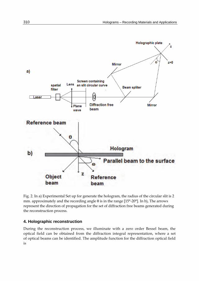
Fig. 2. In a) Experimental Set up for generate the hologram, the radius of the circular slit is 2 mm. approximately and the recording angle θ is in the range [15°-20°]. In b), The arrows represent the direction of propagation for the set of diffraction free beams generated during the reconstruction process.
4. Holographic reconstruction During the reconstruction process, we illuminate with a zero order Bessel beam, the optical field can be obtained from the diffraction integral representation, where a set of optical beams can be identified. The amplitude function for the diffraction optical field is
Holographic Synthesis of Diffraction Free Beams and Dark Hollow Beams
311
( ) ( ) ( ) { } { }
( ) ( ) { } { }
( ) ( ) { } { }
2 22 2 20 0
2 22 2 20 0
2 22 2 20 0
exp, , 2 exp
expexp
expexp
ikrx y z J ax y J ax y i ax dxdy
rikr
J ax y J ax y i ax dxdyr
ikrJ ax y J ax y i ax dxdy
r
φ μ μ ξ
μ μ ξ
μ μ ξ
= + + − +
+ + +
+ + −
(15)
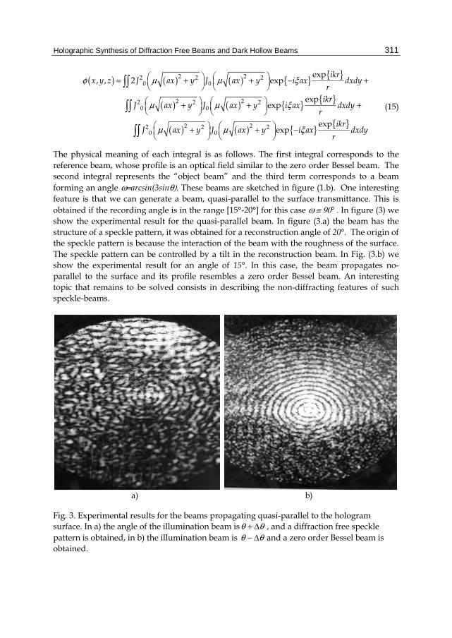
The physical meaning of each integral is as follows. The first integral corresponds to the reference beam, whose profile is an optical field similar to the zero order Bessel beam. The second integral represents the “object beam” and the third term corresponds to a beam forming an angle ω=arcsin(3sinθ). These beams are sketched in figure (1.b). One interesting feature is that we can generate a beam, quasi-parallel to the surface transmittance. This is obtained if the recording angle is in the range [15°-20°] for this case ω ≅ 90° . In figure (3) we show the experimental result for the quasi-parallel beam. In figure (3.a) the beam has the structure of a speckle pattern, it was obtained for a reconstruction angle of 20°. The origin of the speckle pattern is because the interaction of the beam with the roughness of the surface. The speckle pattern can be controlled by a tilt in the reconstruction beam. In Fig. (3.b) we show the experimental result for an angle of 15°. In this case, the beam propagates no-parallel to the surface and its profile resembles a zero order Bessel beam. An interesting topic that remains to be solved consists in describing the non-diffracting features of such speckle-beams.
a) b)
Fig. 3. Experimental results for the beams propagating quasi-parallel to the hologram surface. In a) the angle of the illumination beam isθ θ+ Δ , and a diffraction free speckle pattern is obtained, in b) the illumination beam is θ θ− Δ and a zero order Bessel beam is obtained.
Holograms – Recording Materials and Applications
312
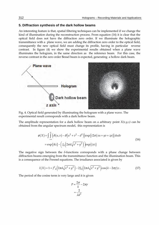
5. Diffraction synthesis of the dark hollow beams An interesting feature is that, spatial filtering techniques can be implemented if we change the kind of illumination during the reconstruction process. From equation (14) it is clear that the optical field does not have the diffraction zero order. If we illuminate the holographic transmittance with a plane wave, we are adding the diffraction zero order to the optical field, consequently the new optical field must change its profile, having in particular reverse contrast. In figure (4) we show the experimental results obtained when a plane wave illuminates the hologram, in the same direction as the reference beam. For this case, the reverse contrast in the zero order Bessel beam is expected, generating a hollow dark beam.
Fig. 4. Optical field generated by illuminating the hologram with a plane wave. The experimental result corresponds with a dark hollow beam.
The amplitude representation for a dark hollow beam on a arbitrary point X(x,y,z) can be obtained from the angular spectrum model, this representation is
( ) ( ) ( )( ) ( ){ }
{ } ( ) { }
2 2 2
2 20
, exp 2
exp 2 exp
X u v u v d i xu yv zp dudv
ikz J d x y i z
φ δ δ π
π γ
∞
−∞
= − + − + +
= − +
(16)
The negative sign between the δ-functions corresponds with a phase change between diffraction beams emerging from the transmittance function and the illumination beam. This is a consequence of the Fresnel equations. The irradiance associated is given by
( ) ( ) ( ) ( )2 2 2 2 20 01 2 2 2 cos 2I X J d x y J d x y k zπ π πγ= + + − + − . (17)
The period of the cosine term is very large and it is given
2
22
2
Pk
d
π πγ
λ
= −
≈
Holographic Synthesis of Diffraction Free Beams and Dark Hollow Beams
313
The consequence of this large period is that in z≥0 region, the irradiance can be approximated as
( ) ( )2 2 201 2I X J d x yπ= − + ,
that explains the contrast reverse. It must be noted for this approximation that dark hollow beams are not depending on the z coordinate. For this reason, dark hollow beams may be interpreted as quasi-diffraction free beams. The experimental results shown in figure (4) are in very good agreement with the theoretical model presented.
6. Final remarks In this chapter we have described a simple method using holographic techniques in order to generate a variety of diffraction free beams and dark hollow beams. A fundamental part of the study consists in the generation of the boundary condition for the optical field characterized by a transmittance function. This is obtained by interfering two zero order Bessel beams. However, our model can be easily extended to other kind of diffracting free beams. During the reconstruction process, the transmittance function can be illuminated with different kinds of optical fields incorporating in this way spatial filtering techniques. The analysis showed allowed us to generate simultaneously a set of diffraction free beams and dark hollow beams with profiles and phases easily tunable. An important fact is that, we can generate diffracting free beams quasi-parallel to the hologram surface. This offers the possibility to study the self regeneration property of the electromagnetic field associated to the diffraction free beams, also, this beam offers the possibility to be implemented as surface optical twisters to transfer angular momentum perpendicular to the surface for the development of micro-motors and it can be implemented for the synthesis of surface plasmon waves.
7. References [1] Hariharan, P, “Colour Holography”, Progress in optics 20, Elsevier Science, 1983,
Chapter 4, p.p. 265-321 North Holland. [2] Christian Frere and Olof Bryngdahl, “ Computer-Generated Holograms: Reconstruction
of curves in 3-D”, Opt. Comm., Vol 60, 6, pp. 369-372 [3] Feng Gao, Jianhua Zhu, Qizhong Huang, Yixiao Zhang, Yangsu Zeng, Fuhua Gao,
Yongkang Guo, Zheng Cui, “Electron-beam lithography to improve quality of computer- generated hologram” Microelectronic Engineering, Vol. 61-62, 2002 pp. 363-369
[4] C. S. West and K. A. O'Donnell, "Observations of backscattering enhancement from polaritons on a rough metal surface," J. Opt. Soc. Am. A ,12, 390-397 (1995)
[5] G. Martinez-Niconoff, J. A. Sanchez-Gil, H. H. Sanchez Hernandez and A. Perez Leija, “Self Imaging and caustic in two dimensional plasmon optics” Opt. Comm., 281, Vol. 8 (2008), p.p. 2316-2320
Holograms – Recording Materials and Applications
314
[6] G. Martinez Niconoff, P. Martinez-Vara, J. Muñoz-Lopez, J.C. Juarez M and A. Carbajal-Dominguez “Partially coherent surface plasmon modes” Journal of the European of the Optical Society, 6,1109(2011)
[7] G. Bernine, “Small-amplitude perturbation theory for two dimensional surfaces, in light scattering and nanoscale surface roughness”, Ed. A. A. Maradudin (Springer-Verlag, Ney York, 2007).
[8] T.A. Leskova, M. Leyva-Lucero, E. R. Mendez, A.A. Maradudin, I.V. Novikov, “The surface enhanced second harmonic generation of light from a randomly rough metal surface in the Kretschmann geometry” Opt. Comm., 183, 529, 2000
[9] E. Korolev, “Dynamic holography in alkali metal vapour”, Optics and Laser Technology, Vol. 28, 4, (1996), 277-284
[10] 10.- Ryan M. Camacho, Preveen K. Vudyasetu A and John C. Howell, “Four-wave-mixing stopped light in hot atomic rubidium vapour”, Nature photonics 3,103 (2009)
[11] D.L. Mill, “Nonlinear Optics: Basic concepts” 2nd ed. (Springer-Verlag, New York, 1998).
[12] R.W. Boyd, “Nonlinear Optics”, 3rd ed. (Academic press, 2008) [13] J. Arlt, V. Garces-Chavez, W. Sibbett and K. Dholakia, “Optical micromanipulation
using a Bessel light beam”, Opt. Comm, 197, 239-245 (2001) [14] D. P. Rhodes, G.P.T. Lancaster, J. Livesey, D. Mcgloin, J. Arlt and K. Dholakia,
“Guiding a cold atomic beam along a co-propagating and oblique hollow light guide”, Opt. Comm., 214, 247-254 (2002)
[15] J. Durnin, “Exact solutions for diffraction free beams I: the scalar theory” J. Opt. Soc. Am. A, Vol 4, 651-654 (1987)
[16] Andrey S. Ostrovsky, Gabriel Martinez Niconoff and Julio C. Ramirez San-Juan, “Generation of light string and light capillary beams”, Opt. Comm., 207, (2002), 131-138
[17] Gabriel Martinez Niconoff, Julio C. Ramirez San-Juan, Patricia Martinez Vara, Adrian Carbajal Dominguez and Andrey S. Ostrovsky., “Generation of partially coherent diffraction free fields with tunable geometry”, J. Opt. Soc. Am. A, Vol. 21, No. 4, (2004)
[18] Jianping Yin, Weijian Gao and YifunZhu, “Generation of dark hollow beams and their applications”, Progress in Optics 45, Elsevier Science 2003, Chapter 3,pp 119. North Holland.
[19] Andrey S. Ostrovsky, Gabriel Martinez Niconoff, Julio C. Ramirez San Juan, “Coherent Mode representation of propagation-invariant fields”, Opt. Comm., 195 (2001), 27-34
[20] Hariharan, P., “Optical Holography: Principles, Techniques, and Applications”. Cambridge University Press., New York, USA, 1984, pp 23-25
[21] K. Patorski, “The self Imaging phenomenon and its applications” Progress in Optics Vol. 27 Chapter 1, pp 3-108 Elsevier Science 1990 North Holland.