monotonic response of exposed base plates of columns
TRANSCRIPT
Metals 2020, 10, 396; doi:10.3390/met10030396 www.mdpi.com/journal/metals
Article
Monotonic Response of Exposed Base Plates of Columns: Numerical Study and a New Design Method
Héctor Díaz 1, Eduardo Nuñez 2, * and Claudio Oyarzo-Vera 2
1 Instituto de Materiales y Modelos Estructurales. Ciudad Universitaria, Universidad Central de Venezuela,
Facultad de Ingeniería, 1051 Los Chaguaramos Caracas, Venezuela; [email protected] 2 Depto. Ingeniería Civil. Alonso de Ribera 2850, Facultad de Ingeniería, Universidad Católica de la
Santísima Concepción, Concepción 4090541, Chile; [email protected]
* Correspondence: [email protected]; Tel.: +56-9-5127-7382
Received: 27 February 2020; Accepted: 18 March 2020; Published: 19 March 2020
Abstract: This paper describes a numerical study of the behavior of exposed base plates of columns
under the action of axial and bending loads. The aim of this research is to evaluate numerically the
failure mechanisms on stiffened and non-stiffened base plates and propose a new design method.
The effects of base plate thickness, location of anchor rods, location of stiffeners and tensile strength
of anchor rods were considered in the analysis. Sixteen finite elements simulations were performed
considering different combinations of the above mentioned parameters. The results show a fragile
response in the base plates when high resistance anchor rods are used. The anchor rods worked as
fuse elements in base plates with a large thickness or many stiffeners. Additionally, the models with
anchor bars located outside of the column flanges showed lower flexural strength and rotational
stiffness compared to the models with anchor rods located between column flanges. The simulations
showed that the base plate strength was determined by the simultaneous failure mechanisms of two
or more components, different to what is stated in current design guides. Finally, the new method
is suitable to design base plates with stiffened and not stiffened configurations, which unlike
traditional design methods, show a good adjustment with numerical models.
Keywords: exposed column; base plate; stiffeners; yield line; anchor rods; rotational stiffness;
ductility
1. Introduction
The base plates correspond to one of the most frequent column connections of steel structures.
These connections are responsible for transferring loads from the superstructure to the foundations.
However, the performance of these connections was deficient during recent seismic events in the
USA and Japan, where significant damage and failure of these joint elements was reported [1,2].
An exposed column base consists of several components, such as: column sections, base plate,
stiffeners, anchor rods, concrete foundation and shear-lug. Each of these components affects the
connection’s capacity to withstand axial load, shear load and bending moments. Current design
methods, such as those presented in the AISC Steel Design Guide 1 [3], provide design procedures
that allow for sizing of the base plate of exposed columns and their anchor rods. However, these
design methods do not consider combined failure mechanisms, such as those observed in several
experimental studies [4], resulting in non-conservative designs. In other cases, as the current
guidelines do not consider joint configurations with stiffeners, the design often specifies plates with
thicknesses that is not commercially available [5].
Numerical studies using finite elements indicate that the base plates designed using the current
guidelines do not behave as expected, leading to premature crushing of concrete when using base
Metals 2020, 10, 396 2 of 21
plates with thickness higher than 25 mm [6]. A recent experimental study on exposed base plates
considering axial load and bending moment [7] showed an important correlation between the
thickness of the base plate and the performance of the connection. This study concludes that despite
complying with the design guidelines, flexural capacity may not be reliable due to plate interaction
with other components such as the anchors. On the other hand, few studies have addressed the
behavior of column bases with stiffened base plates, which are very common in the practices of
detailing and construction of steel structures, as it allows for reducing the thicknesses of base plates
[8,9]. However, there are no numerically or experimentally validated design procedures that consider
the different performance of stiffened and non-stiffened base plates. The response of connections in
terms of stiffness, strength, rotational capacity and energy dissipation is heavily dependent on the
details of connection and, therefore, on the components considering their location and individual
strength [10]. These problems could be alternatively solved by improving material properties or by
the use of novel nanostructured materials, which have emerged to allow the synergy of high strength
and high ductility modifying failure mechanisms [11]. However, it is usually preferred an
engineering and constructive solution, using currently commonly used materials.
The exposed and embedded base plate connection have been researched by [12–15], obtaining
that rotational fixity of base plate in steel moment resisting frames strongly influences their seismic
response. However, the stiffened base plates were not considered by this investigation.
In this investigation, a numerical study on the behavior of stiffened and non-stiffened base plates
is carried out, considering the contribution of different components to each configuration. The aim of
the research is to evaluate numerically the failure mechanisms in stiffened and non-stiffened base
plates. Additionally, due to currents design methods are focused in non-stiffened base plates a new
design method is proposed. The numerical study was conducted using finite element models
considering material, geometric and contact nonlinear properties. Axial load and bending moment
were simultaneously applied with the goal of identifying the behavior of the base plate and its
interaction with the stiffeners and anchor rods. The welds were designed to remain within the elastic
range and to develop the inelastic behavior of the connected elements, being considered as ideal
monolithic contacts in the numerical models. Similarly, concrete was designed to remain elastic.
These conditions are like those observed on typical connection tests that intend to evaluate the seismic
performance of the links, avoiding a fragile failure of elements with limited inelastic capacity, such
as, welding and concrete. In the final part of the paper, the authors propose a new design method
based on yield lines theory, suitable to design base plates with stiffened and not stiffened
configurations.
2. Numerical Study
2.1. Specimens under Analysis
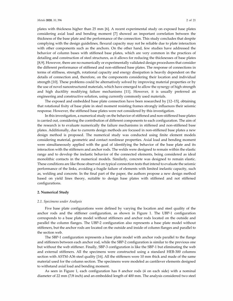
Five base plate configurations were defined by varying the location and steel quality of the
anchor rods and the stiffener configuration, as shown in Figure 1. The UBP-1 configuration
corresponds to a base plate model without stiffeners and anchor rods located on the outside and
parallel the column flanges. The UBP-2 configuration also represents a base plate model without
stiffeners, but the anchor rods are located on the outside and inside of column flanges and parallel to
the section web.
The SBP-1 configuration represents a base plate model with anchor rods parallel to the flange
and stiffeners between each anchor rod, while the SBP-2 configuration is similar to the previous one
but without the web stiffener. Finally, SBP-3 configuration is like the SBP-1 but eliminating the web
and external stiffeners. All the specimens were constructed using a standard HEB-300 columns
section with ASTM-A36 steel quality [16]. All the stiffeners were 10 mm thick and made of the same
material used for the column section. The specimens were modeled as cantilever elements designed
to withstand axial load and bending moment.
As seen in Figure 1, each configuration has 8 anchor rods (4 on each side) with a nominal
diameter of 22 mm (7/8 inch) and an embedded length of 400 mm. The analysis considered two steel

Metals 2020, 10, 396 3 of 21
qualities for the anchor rods: ASTM-A36 quality [16] and ASTM-A193 quality [17]. The washers and
the holes in the base plate were sized according to the recommendations presented in the AISC
Design Guide 1 [3]. The spacing be-tween the anchor bars was selected to comply with what is
specified in section D.8.2 of ACI Code 318-14 [18].
The column was supported by a square concrete foundation (700 mm × 700 mm) with a
characteristic compressive strength of concrete equal to f’c = 25 MPa. The parameters considered in
this analysis are presented in Table 1, where tp, g, ts, dr and Fur represents the base plate thickness,
gage, stiffeners thickness, anchor rods diameter and ultimate tensile strength of anchor rods,
respectively.
Table 1. Simulations matrix.
Model tp (mm) g (mm) ts (mm) dr (mm) Fur (mm)
UBP-1-1 19 N/A N/A 22 408
UBP-1-2 25 N/A N/A 22 408
UBP-1-3 38 N/A N/A 22 408
UBP-1-4 19 N/A N/A 22 878
UBP-1-5 25 N/A N/A 22 878
UBP-1-6 38 N/A N/A 22 878
UBP-2-1 25 210 N/A 22 408
UBP-2-2 25 390 N/A 22 408
UBP-2-3 25 210 N/A 22 878
UBP-2-4 25 390 N/A 22 878
SBP-1-1 19 N/A 10 22 408
SBP-1-2 19 N/A 10 22 878
SBP-2-1 19 N/A 10 22 408
SBP-2-2 19 N/A 10 22 878
SBP-3-1 19 N/A 10 22 408
SBP-3-2 19 N/A 10 22 878
Metals 2020, 10, 396 4 of 21
Figure 1. Specimen configurations.
2.2. Finite Element Models
A numerical study was carried out using the finite element method with ANSYS software [19],
considering the variables involved in the design, such as: thickness of the base plate, location of the
anchor rods, stiffener configuration and ultimate tensile strength of anchor rods. Secondary
components such as grouting material and leveling nuts were not included in the models.
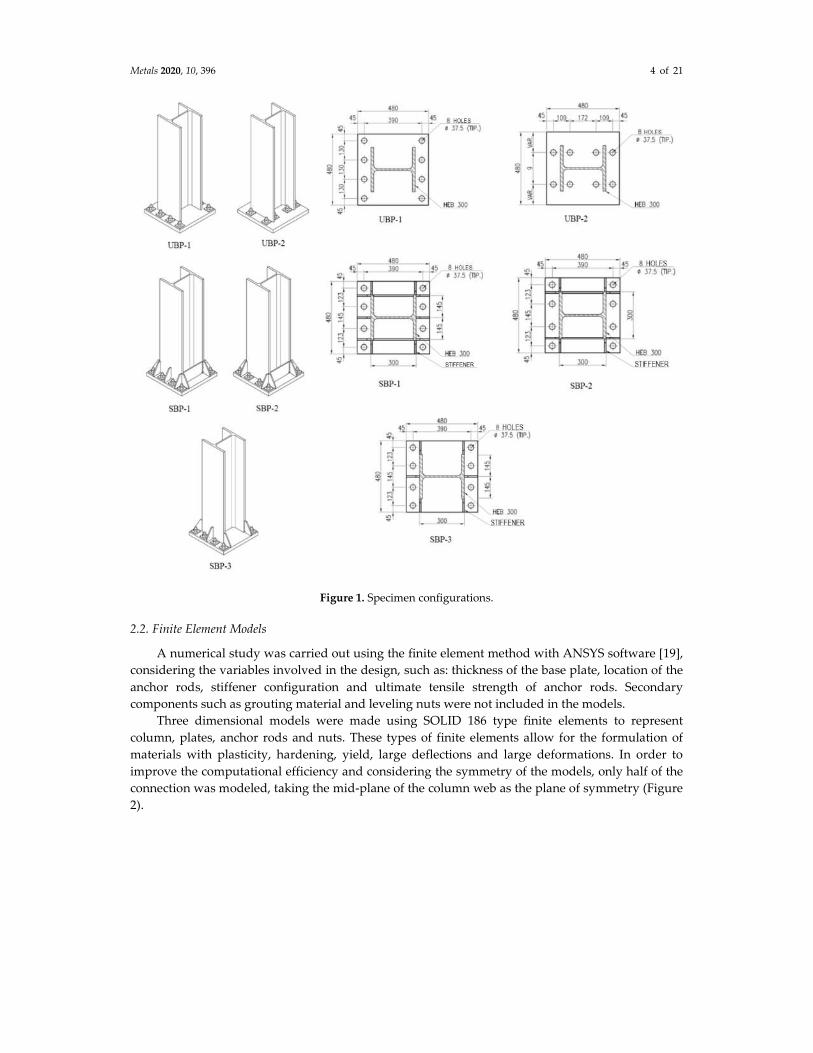
Three dimensional models were made using SOLID 186 type finite elements to represent
column, plates, anchor rods and nuts. These types of finite elements allow for the formulation of
materials with plasticity, hardening, yield, large deflections and large deformations. In order to
improve the computational efficiency and considering the symmetry of the models, only half of the
connection was modeled, taking the mid-plane of the column web as the plane of symmetry (Figure
2).
Metals 2020, 10, 396 5 of 21
Figure 2. Finite element models for each specimen configuration.
To incorporate the effect of diameter reducing on the anchor rods, each anchor rod on the model
consists of two parts, representing the threaded section and the non-threaded section. The threaded
part was modeled with an equivalent diameter, such that its cross section has the reduced area. The
concrete foundation was modeled with a height equal to the embedded depth of the anchor rods (400
mm) and with fully fixed support condition in its base. Along the vertical symmetry plane,
“frictionless” type constraints were assigned to simulate the behavior of the entire specimen.
Between the base plate and the surface of the foundation, a “frictional” type contact surface was
assigned considering a friction coefficient between steel and concrete equal to 0.45, according to
previous experimental studies [20]. Similarly, a “frictional” type contact surface was assigned
between the anchor rod and the concrete with the same coefficient of friction. The nut-washer contact
and anchor rod-washer contact were simulated in a simplified way by assigning “frictionless” type
contacts. This type of contact allows a separation between the connected parts and a tangential
movement without friction. To simulate the welded joint between the column, the base plate and the
stiffeners, a “bonded” type contact was assigned, which prevents any type of relative movement.
Different constitutive laws were used to characterize the behavior of the materials considered in
the model. These curves were adjusted by applying Equations (1) and (2) (actual stress and strain) to
describe the multiaxial behavior of steel from the uniaxial behavior depicted by the results of the
uniaxial tensile test.
ε���� = ln (1 + ε) (1)
σ���� = σ (1 + ε) (2)
where,
ε = normal strain obtained from uniaxial tensile test.
σ = normal stress obtained from uniaxial tensile test.

Metals 2020, 10, 396 6 of 21
��� = real normal strain.
�� = real normal stress.
For the ASTM-A36 steel elements (base plate, stiffeners and steel anchors), a multilinear model
with hardening due to strain was used, according to [21]. The material for the high strength steel
anchor rods was modeled as multilinear with hardening due to strain, according to [22]. The uniaxial
compression stress–strain curve of concrete was defined as a multilinear model, according to [23,24].
The curves of the materials used are shown in Figure 3.
(a) (b) (c)
Figure 3. Constitutive models considered for (a) ASTM-A36 steel, (b) ASTM-A193 steel and (c)
concrete.
2.3. Loading Protocol
Each specimen was analyzed under the action of a lateral load applied parallel to the column’s
web. Additionally, a constant compression axial load equal to 50 [T] was applied. The lateral load
was applied monotonically following the scheme of a displacement protocol. These displacements
were applied at 2 m above the top of the base plate, corresponding approximately to the inflection
point in a column of moment resistant frame with fully fixed supports.
Under seismic conditions, a base plate can be loaded in a non-proportional manner, such that
the axial load remains constant while flexural deformations vary and are reversed [4]. For this reason,
the axial compression force and lateral displacement were defined in the numerical model as two
separate loading steps: first the axial load is applied and then displacements are imposed until failure
of the connection (Figure 4).
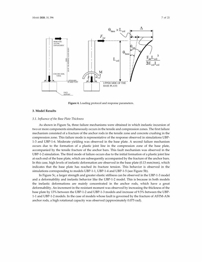
2.4. Response Parameters
In each of the simulations, the lateral force was recorded according to the displacement protocol
applied at the top of the column, as well as the sliding measured at the bottom of the base plate. From
these results, the moment–rotation response was obtained using the following equations:
M = F��� × L��� (3)
θ���� = �∆ −F��� ∙ L���
�
3 ∙ E��� ∙ I���� ∙
1
L��� (4)
where,
F��� = Lateral load.
∆ = Relative displacement between top and base of the column.
E��� = Column Young’s modulus (2.1 × 10⁵ MPa).
I��� = Moment of inertia of the column section.
L��� = Load application point height.
From the moment–rotation curves the following results were obtained (Figure 4): Maximum
connection moment, (Mmax), yielding moment of the connection (My), rotation at yielding (θy),
rotation at maximum moment (θ_max) and the elastic rotational stiffness of the connection (βy =
My⁄θy ).
Metals 2020, 10, 396 7 of 21
Figure 4. Loading protocol and response parameters.
3. Model Results
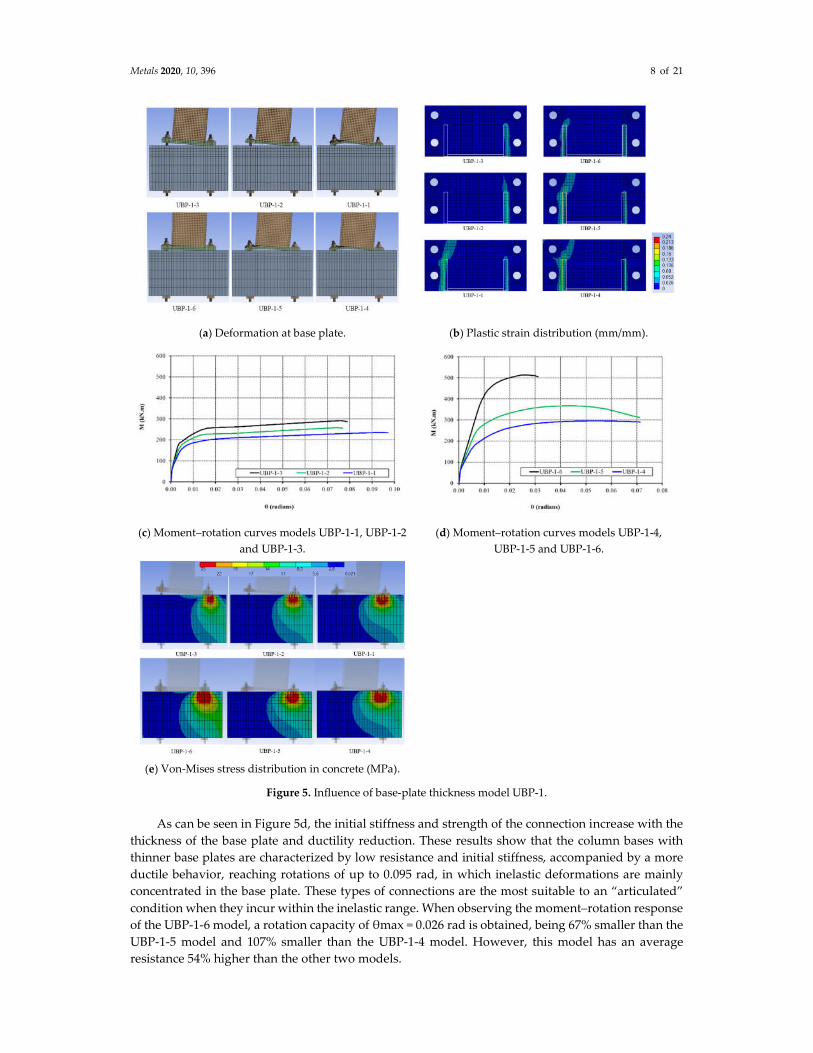
3.1. Influence of the Base Plate Thickness
As shown in Figure 5a, three failure mechanisms were obtained in which inelastic incursion of
two or more components simultaneously occurs in the tensile and compression zones. The first failure
mechanism consisted of a fracture of the anchor rods in the tensile zone and concrete crushing in the
compression zone. This failure mode is representative of the response observed in simulations UBP-
1-3 and UBP-1-6. Moderate yielding was observed in the base plate. A second failure mechanism
occurs due to the formation of a plastic joint line in the compression zone of the base plate,
accompanied by the tensile fracture of the anchor bars. This fault mechanism was observed in the
UBP-1-2 simulation. The third mode of failure occurs due to the initial formation of a plastic joint line
at each end of the base plate, which are subsequently accompanied by the fracture of the anchor bars.
In this case, high levels of inelastic deformation are observed in the base plate (0.13 mm/mm), which
indicates that the base plate has reached its fracture tension. This behavior is observed in the
simulations corresponding to models UBP-1-1, UBP-1-4 and UBP-1-5 (see Figure 5b).
In Figure 5c, a larger strength and greater elastic stiffness can be observed in the UBP-1-3 model
and a deformability and inelastic behavior like the UBP-1-2 model. This is because in both models
the inelastic deformations are mainly concentrated in the anchor rods, which have a great
deformability. An increment in the resistant moment was observed by increasing the thickness of the
base plate by 13% between the UBP-1-2 and UBP-1-3 models and increase of 9.5% between the UBP-
1-1 and UBP-1-2 models. In the case of models whose fault is governed by the fracture of ASTM-A36
anchor rods, a high rotational capacity was observed (approximately 0.075 rad).
Metals 2020, 10, 396 8 of 21
(a) Deformation at base plate. (b) Plastic strain distribution (mm/mm).
(c) Moment–rotation curves models UBP-1-1, UBP-1-2
and UBP-1-3.
(d) Moment–rotation curves models UBP-1-4,
UBP-1-5 and UBP-1-6.
(e) Von-Mises stress distribution in concrete (MPa).
Figure 5. Influence of base-plate thickness model UBP-1.
As can be seen in Figure 5d, the initial stiffness and strength of the connection increase with the
thickness of the base plate and ductility reduction. These results show that the column bases with
thinner base plates are characterized by low resistance and initial stiffness, accompanied by a more
ductile behavior, reaching rotations of up to 0.095 rad, in which inelastic deformations are mainly
concentrated in the base plate. These types of connections are the most suitable to an “articulated”
condition when they incur within the inelastic range. When observing the moment–rotation response
of the UBP-1-6 model, a rotation capacity of θmax = 0.026 rad is obtained, being 67% smaller than the
UBP-1-5 model and 107% smaller than the UBP-1-4 model. However, this model has an average
resistance 54% higher than the other two models.

Metals 2020, 10, 396 9 of 21
The tension distribution in the concrete due to the pressure applied by the base plate is shown
in Figure 5e. A variation of the area in which the maximum tensions are concentrated was observed,
which was dependent on the thickness of the base plate. In general, it can be seen that in the case of
models with more rigid base plates (38 mm), the maximum tensions are concentrated at the end of
the base plate, unlike the models with more flexible base plates (19 mm) where the stresses are
distributed over a wider area once the flexural yielding of the base plate occurred.
In summary, in the non-stiffened base plates with A36 steel anchor rods, a loss of ductility
appears as the thickness increases and the inelastic incursion is concentrated in anchor rods.
Therefore, when A193 steel anchor rods are used, a loss of ductility with increase of strength and
stiffened is reached as the thickness of the base plate increases. These effects must be considered in
the global seismic analysis of steel structure.
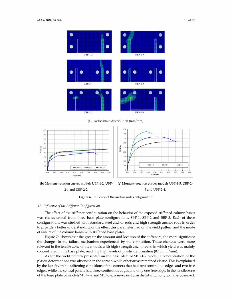
3.2. Influence of the Anchor Rods Configuration
The specimens UBP-1-2, UBP-2-1 and UBP-2-2 (25 mm thick base plates, without stiffeners) were
fixed to the base by ASTM A36 anchors rods, and in UBP-1-5 models, the specimens UBP-2-3, UBP-
2-4 (25 mm thick base plates, without stiffeners) were fixed with ASTM A193 anchors anchor rods.
These two kinds of configurations were compared in order to assess the effect of the anchor strength
on the yielding pattern and failure mode of the connection.
As can be seen in Figure 6a, the location of the anchor bars significantly affected the distribution
of base plate’s deformations, being more evident in the tensile zone of the models with high strength
anchor bars. Additionally, a lower plastic deformation was observed in the base plates where anchor
bars are located parallel and closer to the column web (UBP-2-1 and UBP-2-3). This condition suggests
the base plates have a larger bending strength when fixed following this anchor setting.
In the configurations with ASTM A36 steel anchor rods, a similarity was observed in the resistant
moment of the column bases with anchors parallel to the column web (UBP-2-1 and UBP-2-2), as
shown in Figure 6b. The difference between the resistant moment of these two connections was 1.2%.
In both cases the fault was governed mainly by the fracture of the anchor rods, and not by the flexural
yielding of the base plate in the traction zone. On the other hand, there was also a lower strength in
the column base with anchor bars parallel to the flanges (UBP-1-2), due to the difference between the
lever arms, reaching rotations larger than 0.07 rad.
In the configurations with ASTM A193 anchor bars, a concentration of the plastic deformations
in the base plate or the anchor bars is evidenced depending on their configuration. As can be seen in
Figure 6b,c, the UBP-2-3 model had a significantly higher strength, giving a moment 35% larger than
the UBP-2-4 model. This demonstrates that the flexural strength of the base plate in the tensile zone
was influenced by the distance of the anchor rods to the web of the column, which in turn has an
influence on the resistant moment of the connection.
In Figure 6b,c, a lower elastic rotational stiffness and a lager ductility can be seen in those column
bases whose anchor bars were located away from the column web and outside of the column flanges
(UBP-2-2 and UBP-2-4). This indicates that the location of the anchor groups did not significantly
influence the stiffness, but it is important to determine flexural deformation of the base plate in the
traction zone.
In summary, a minor ductility was obtained in the non-stiffened base plates with A36 steel
anchor rods, as the anchor rods configuration was similar to end-plate configuration. However, an
inclined failure mechanism was obtained with anchor rods near from weak axis column restricting
the flexural capacity of base plate. Therefore, when A193 steel anchor rods were used a loss of
ductility with increase of strength and stiffness was reached, as the anchor rods were located
according to end-plate configuration. These effects must be considered in the global seismic analysis
of steel structure.
Metals 2020, 10, 396 10 of 21
(a) Plastic strain distribution (mm/mm).
(b) Moment–rotation curves models UBP-1-2, UBP-
2-1 and UBP-2-2.
(c) Moment–rotation curves models UBP-1-5, UBP-2-
3 and UBP-2-4.
Figure 6. Influence of the anchor rods configuration.
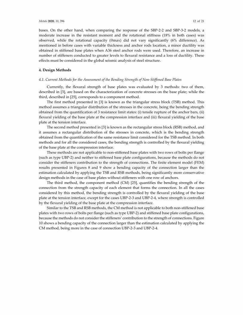
3.3. Influence of the Stiffener Configuration
The effect of the stiffener configuration on the behavior of the exposed stiffened column bases
was characterized from three base plate configurations, SBP-1, SBP-2 and SBP-3. Each of these
configurations was studied with standard steel anchor rods and high strength anchor rods in order
to provide a better understanding of the effect this parameter had on the yield pattern and the mode
of failure of the column bases with stiffened base plates.
Figure 7a shows that the greater the amount and location of the stiffeners, the more significant
the changes in the failure mechanism experienced by the connection. These changes were more
relevant in the tensile zone of the models with high strength anchor bars, in which yield was mainly
concentrated in the base plate, reaching high levels of plastic deformation (0.10 mm/mm).
As for the yield pattern presented on the base plate of SBP-1-2 model, a concentration of the
plastic deformations was observed in the corner, while other areas remained elastic. This is explained
by the less favorable stiffening conditions of the corners that had two continuous edges and two free
edges, while the central panels had three continuous edges and only one free edge. In the tensile zone
of the base plate of models SBP-2-2 and SBP-3-2, a more uniform distribution of yield was observed.

Metals 2020, 10, 396 11 of 21
Additionally, in all of the models, flexural yield was reached in the compression zone of the base
plate and axial yield (tension or compression) on the stiffener (see Figure 7b).
The moment–rotation curves presented in Figure 7c,d show small differences in the resistant
moment of the group of column bases with stiffeners. On average, the resistant moment of these three
connections differed only by 4.5%. This difference, although not very significant, could mainly be
attributed to the resistance provided by the stiffeners in the compression zone, where the amount
varies for each model. On the other hand, these specimens show a good rotation capacity, reaching
rotations close to 0.07 rad. This relatively high ductility was provided by the deformation capacity of
the anchor rods, which in this case were made of ordinary steel (ASTM A36).
(a) Plastic strain distribution (mm/mm). (b) Plastic strain distribution on stiffeners
(mm/mm).
(c) Moment–rotation curves models UBP-1-1, SBP-1-
1, SBP-2-1 and SBP-3-1.
(d) Moment–rotation curves models UBP-1-4, SBP-
1-2, SBP-2-2 and SBP-3-2.
Figure 7. Influence of the stiffener configuration.
In the column bases with high strength anchor bars (ASTM A193) a different behavior was
observed. Inelastic deformations were concentrated in the base plate or the anchor rods depending
on the amount and configuration of the stiffeners. The moment–rotation curves of Figure 7 show that
connections SBP-1-2 and SBP-2-2 models had similar moment resistance (only a 1.7% of difference),
although they had different amounts of stiffeners. The same figure also shows that SBP-2-2 model
reached a maximum rotation of 87% greater than that achieved by the SBP-1-2 model, showing that
the amount and configuration of stiffeners affected the strength and ductility of exposed column
Metals 2020, 10, 396 12 of 21
bases. On the other hand, when comparing the response of the SBP-2-2 and SBP-3-2 models, a
moderate increase in the resistant moment and the rotational stiffness (18% in both cases) was
observed, while the rotational capacity (θmax) did not vary significantly (6% difference). As
mentioned in before cases with variable thickness and anchor rods location, a minor ductility was
obtained in stiffened base plates when A36 steel anchor rods were used. Therefore, an increase in
number of stiffeners conducted to greater levels to flexural resistance and a loss of ductility. These
effects must be considered in the global seismic analysis of steel structure.
4. Design Methods
4.1. Current Methods for the Assessment of the Bending Strength of Non-Stiffened Base Plates
Currently, the flexural strength of base plates was evaluated by 3 methods: two of them,
described in [3], are based on the characterization of concrete stresses on the base plate; while the
third, described in [25], corresponds to a component method.
The first method presented in [3] is known as the triangular stress block (TSB) method. This
method assumes a triangular distribution of the stresses in the concrete, being the bending strength
obtained from the quantification of 3 resistance limit states: (i) tensile rupture of the anchor bars, (ii)
flexural yielding of the base plate at the compression interface and (iii) flexural yielding of the base
plate at the tension interface.
The second method presented in [3] is known as the rectangular stress block (RSB) method, and
it assumes a rectangular distribution of the stresses in concrete, which is the bending strength
obtained from the quantification of the same resistance limit considered for the TSB method. In both
methods and for all the considered cases, the bending strength is controlled by the flexural yielding
of the base plate at the compression interface.
These methods are not applicable to non-stiffened base plates with two rows of bolts per flange
(such as type UBP-2) and neither to stiffened base plate configurations, because the methods do not
consider the stiffeners contribution to the strength of connections. The finite element model (FEM)
results presented in Figures 8 and 9 show a bending capacity of the connection larger than the
estimation calculated by applying the TSB and RSB methods, being significantly more conservative
design methods in the case of base plates without stiffeners with one row of anchors.
The third method, the component method (CM) [25], quantifies the bending strength of the
connection from the strength capacity of each element that forms the connection. In all the cases
considered by this method, the bending strength is controlled by the flexural yielding of the base
plate at the tension interface, except for the cases UBP-2-3 and UBP-2-4, where strength is controlled
by the flexural yielding of the base plate at the compression interface.
Similar to the TSB and RSB methods, the CM method is not applicable to both non-stiffened base
plates with two rows of bolts per flange (such as type UBP-2) and stiffened base plate configurations,
because the methods do not consider the stiffeners’ contribution to the strength of connections. Figure
10 shows a bending capacity of the connection larger than the estimation calculated by applying the
CM method, being more in the case of connection UBP-2-3 and UBP-2-4.

Metals 2020, 10, 396 13 of 21
Figure 8. Comparison of FEM results with estimations of the triangular stress block (TSB) method.
Figure 9. Comparison of FEM results with estimations of the rectangular stress block (RSB) method.
Figure 10. Comparison of FEM results with estimations of the component method (CM).
4.2. Proposed Methods for the Assessment of the Bending Strength of Stiffened and Non-Stiffened
Connections
The behavior observed in finite element simulations suggests that the maximum strength of the
connection was controlled by different limit states associated to different collapse mechanisms. In
this sense, the current design methods did not allow for accurately reproducing the flexural strength,
Metals 2020, 10, 396 14 of 21
often resulting conservative designs and excluding stiffener base plates configurations that are
frequent and necessary in professional practice.
The novel method proposed here considered the following limit states: (i) flexural yielding of
the base plate, both in the tension zone and in the compression zone (LS1); (ii) flexural yielding of the
base plate and ultimate failure of the anchor bars in the tension interface, combined with flexural
yielding of the base plate at the compression interface (LS2); (iii) ultimate failure of the anchor bars
at the tension interface and flexural yielding of the base plate at the compression interface (LS3); (iv)
ultimate failure of the anchor bars in the tension interface and bearing of concrete in the compression
interface (LS4) and (v) flexural yielding of the base plate and ultimate failure of the anchor bars in the
tension interface, combined with concrete bearing in the compression interface (LS5).
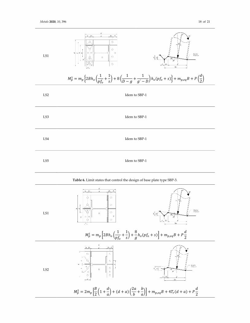
In this novel method, the flexural strength was obtained from the application of the yielding
lines theory, by applying a balance between the work of the external forces and the work of the
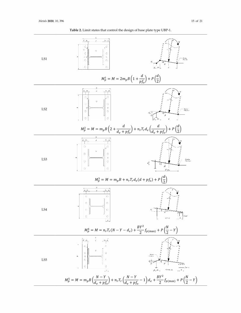
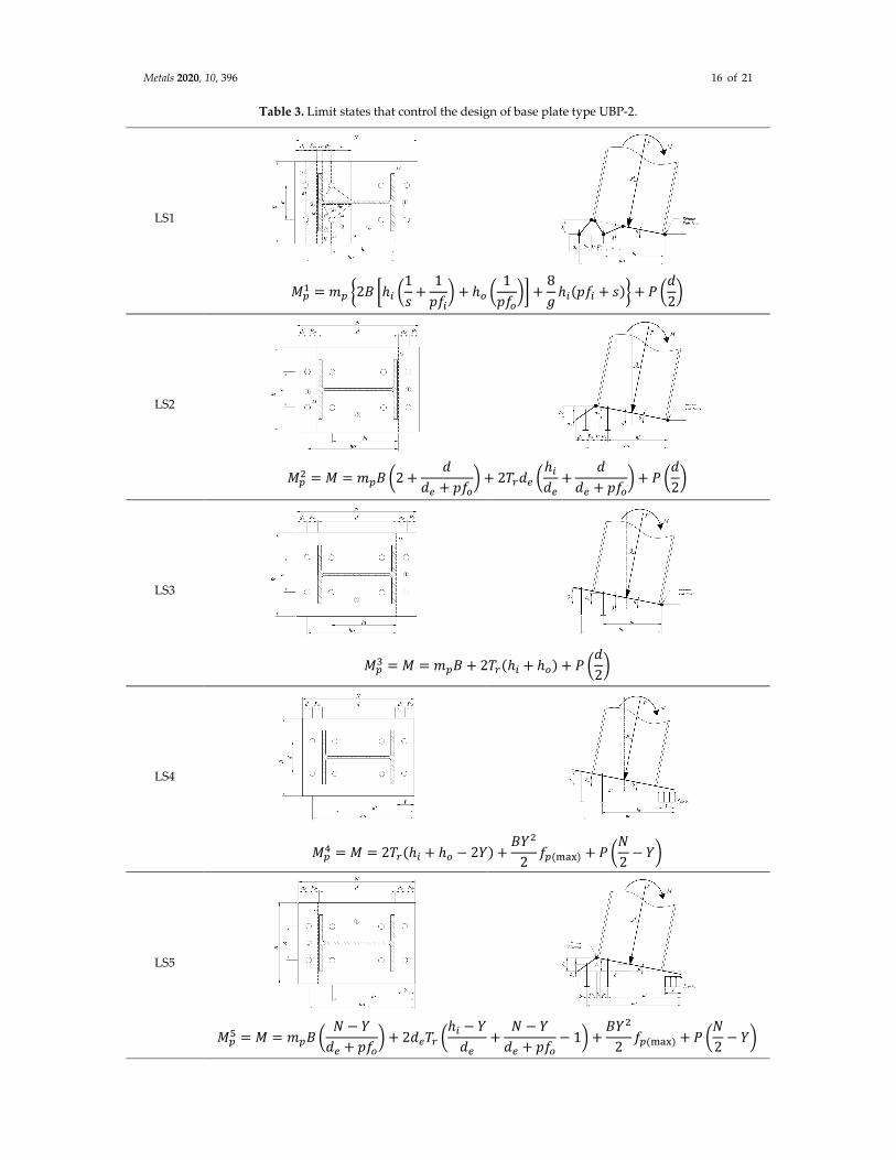
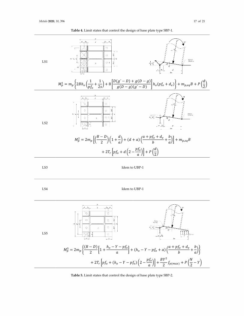
internal forces that occurs for the different collapse mechanisms. Tables 2–6 show the collapse
mechanisms that control the flexural strength of the base plates UBP-1, UBP-2, SBP-1, SBP-2 and SBP-
3, respectively. These tables show the parameterized flexural strength for each failure mechanism.
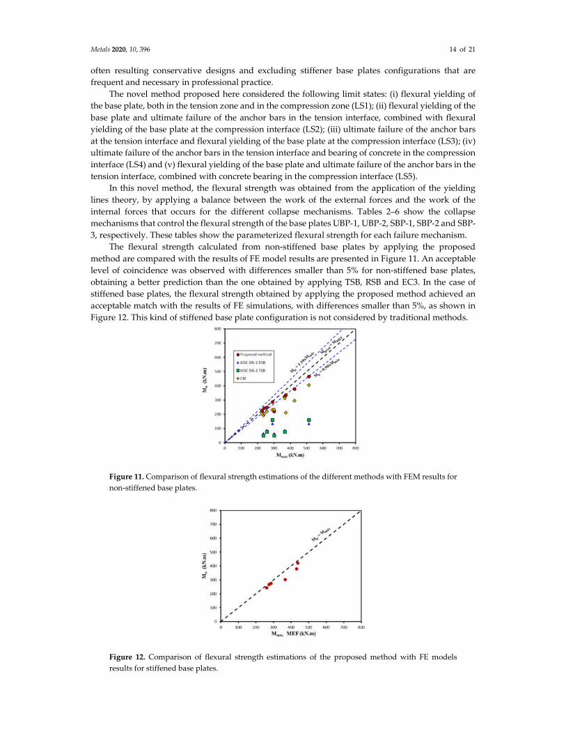
The flexural strength calculated from non-stiffened base plates by applying the proposed
method are compared with the results of FE model results are presented in Figure 11. An acceptable
level of coincidence was observed with differences smaller than 5% for non-stiffened base plates,
obtaining a better prediction than the one obtained by applying TSB, RSB and EC3. In the case of
stiffened base plates, the flexural strength obtained by applying the proposed method achieved an
acceptable match with the results of FE simulations, with differences smaller than 5%, as shown in
Figure 12. This kind of stiffened base plate configuration is not considered by traditional methods.
Figure 11. Comparison of flexural strength estimations of the different methods with FEM results for
non-stiffened base plates.
Figure 12. Comparison of flexural strength estimations of the proposed method with FE models
results for stiffened base plates.
Metals 2020, 10, 396 15 of 21
Table 2. Limit states that control the design of base plate type UBP-1.
LS1
��� = � = 2��� �1 +
�
���� + � �
�
2�
LS2
��� = � = ��� �2 +
�
�� + ���� + ������ �
�
�� + ���� + � �
�
2�
LS3
��� = � = ��� + ������(� + ���) + � �
�
2�
LS4
��� = � = ����(� − � − ��) +
���
2��(���) + � �
�
2− ��
LS5
��� = � = ��� �
� − �
�� + ���� + ���� �
� − �
�� + ���− 1� �� +
���
2��(���) + � �
�
2− ��
Metals 2020, 10, 396 16 of 21
Table 3. Limit states that control the design of base plate type UBP-2.
LS1
��� = �� �2� �ℎ� �
1
�+
1
���� + ℎ� �
1
����� +
8
�ℎ�(��� + �)� + � �
�
2�
LS2
��� = � = ��� �2 +
�
�� + ���� + 2���� �
ℎ�
��+
�
�� + ���� + � �
�
2�
LS3
��� = � = ��� + 2��(ℎ� + ℎ�) + � �
�
2�
LS4
��� = � = 2��(ℎ� + ℎ� − 2�) +
���
2��(���) + � �
�
2− ��
LS5
��� = � = ��� �
� − �
�� + ���� + 2���� �
ℎ� − �
��+
� − �
�� + ���− 1� +
���
2��(���) + � �
�
2− ��
Metals 2020, 10, 396 17 of 21
Table 4. Limit states that control the design of base plate type SBP-1.
LS1
��� = �� �2�ℎ� �
1
���+
1
2�� + 8 �
�(�´ − �) + �(� − �)
�(� − �)(�´ − �)� ℎ�(��� + ��)� + ��,��� + � �
�
2�
LS2
��� = 2�� ��
� − �
2� �1 +
�
�� + (� + �) �
� + ��� + ��
�+
�
��� + ��,���
+ 2�� ���� + � �2 −���
��� + � �
�
2�
LS3 Idem to UBP-1
LS4 Idem to UBP-1
LS5
��� = 2�� �
(� − �)
2�1 +
ℎ� − � − ���
�� + (ℎ� − � − ��� + �) �
� + ��� + ��
�+
�
���
+ 2�� ���� + (ℎ� − � − ���) �2 −���
��� +
���
2��(���) + � �
�
2− ��
Table 5. Limit states that control the design of base plate type SBP-2.
Metals 2020, 10, 396 18 of 21
LS1
��� = �� �2�ℎ� �
1
���+
1
�� + 8 �
1
� − �+
1
�´ − �� ℎ�(��� + �)� + ��,��� + � �
�
2�
LS2 Idem to SBP-1
LS3 Idem to SBP-1
LS4 Idem to SBP-1
LS5 Idem to SBP-1
Table 6. Limit states that control the design of base plate type SBP-3.
LS1
��� = �� �2�ℎ� �
1
���+
1
�� +
8
�ℎ�(��� + �)� + ��,��� + �
�
2
LS2
��� = 2�� �
�
2�1 +
�
�� + (� + �) �
2�
�+
�
��� + ��,��� + 4��(� + �) + �
�
2
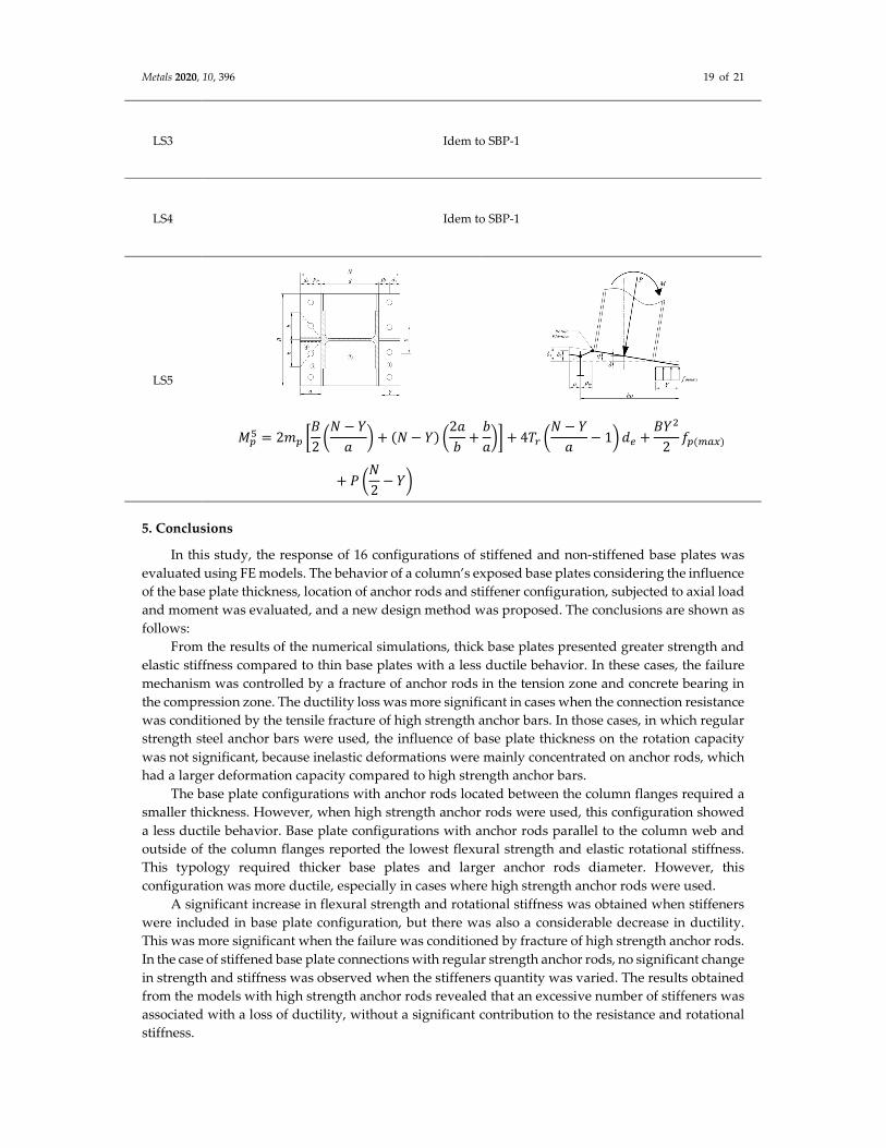
Metals 2020, 10, 396 19 of 21
LS3 Idem to SBP-1
LS4 Idem to SBP-1
LS5
��� = 2�� �
�
2�
� − �
�� + (� − �) �
2�
�+
�
��� + 4�� �
� − �
�− 1� �� +
���
2��(���)
+ � ��
2− ��
5. Conclusions
In this study, the response of 16 configurations of stiffened and non-stiffened base plates was
evaluated using FE models. The behavior of a column’s exposed base plates considering the influence
of the base plate thickness, location of anchor rods and stiffener configuration, subjected to axial load
and moment was evaluated, and a new design method was proposed. The conclusions are shown as
follows:
From the results of the numerical simulations, thick base plates presented greater strength and
elastic stiffness compared to thin base plates with a less ductile behavior. In these cases, the failure
mechanism was controlled by a fracture of anchor rods in the tension zone and concrete bearing in
the compression zone. The ductility loss was more significant in cases when the connection resistance
was conditioned by the tensile fracture of high strength anchor bars. In those cases, in which regular
strength steel anchor bars were used, the influence of base plate thickness on the rotation capacity
was not significant, because inelastic deformations were mainly concentrated on anchor rods, which
had a larger deformation capacity compared to high strength anchor bars.
The base plate configurations with anchor rods located between the column flanges required a
smaller thickness. However, when high strength anchor rods were used, this configuration showed
a less ductile behavior. Base plate configurations with anchor rods parallel to the column web and
outside of the column flanges reported the lowest flexural strength and elastic rotational stiffness.
This typology required thicker base plates and larger anchor rods diameter. However, this
configuration was more ductile, especially in cases where high strength anchor rods were used.
A significant increase in flexural strength and rotational stiffness was obtained when stiffeners
were included in base plate configuration, but there was also a considerable decrease in ductility.
This was more significant when the failure was conditioned by fracture of high strength anchor rods.
In the case of stiffened base plate connections with regular strength anchor rods, no significant change
in strength and stiffness was observed when the stiffeners quantity was varied. The results obtained
from the models with high strength anchor rods revealed that an excessive number of stiffeners was
associated with a loss of ductility, without a significant contribution to the resistance and rotational
stiffness.
Metals 2020, 10, 396 20 of 21
The proposed method allowed an acceptable adjustment with FE models unlike the traditional
design methods with differences smaller than 5%. Additionally, an identification of failure
mechanisms for stiffened and non-stiffened base plates was obtained. Unlike analytical methods, the
FE models verified that the maximum resistance of a base plate was conditioned by the simultaneous
occurrence of the different failure mechanisms and not by the individual failure of any of its
components. In addition, contrasting with the traditional methods, the new design method can
estimate the flexural strength of stiffened and non-stiffened base plates, conducting to lighting
solutions for base plates.
Author Contributions: Conceptualization, E.N.; Methodology, E.N.; Investigation, H.D. and E.N.; Writing—
original draft, E.N. and C.O.; Writing—review and editing, E.N. and C.O.; Funding acquisition, E.N.; Resources,
E.N.; Supervision, E.N. and C.O. All authors have read and agreed to the published version of the manuscript.
Funding: This research received no external funding.
Conflicts of Interest: The authors declare no conflict of interest.
References
1. Grauvilardell, J.; Lee, D.; Hajjar, J.; Dexter, R. Synthesis of Design, Testing and Analysis Research on Steel
Column Base Plate Connections in High-Seismic Zones. Structural Engineering Report, No. ST-04-02. Technical
Report for: Department of Civil Engineering, University of Minnesota: Minneapolis, MN, USA, October
2005.
2. Fahmy, M. Seismic Behavior of Moment-resisting Steel Column Bases. Ph.D. Thesis, Department of Civil
and Environmental Engineering, University of Michigan, 2000.
3. Fisher, J.M.; Kloiber, L.A. Steel Design Guide Series 1–Base Plate and Anchor Rod Design. 2nd Edition,
American Institute of Steel Construction: Chicago, IL USA, 2006.
4. Gomez, I.; Kanvinde, A.; Smith, C.; Deierlein, G. Exposed Column Base Connections Subjected to Axial
Compression and Flexure; Technical Report for: American Institute of Steel Construction, AISC, Chicago, IL
USA, August 2010.
5. Kanvinde, A; Jordan, S.; Cooke, R. Exposed column base plate connections in moment frames —
Simulations and behavioral insights. J. Constr. Steel Res. 2013, 84, 82–93.
6. Lee, D.; Goel, S.; Stojadinovic, B. Exposed column-base plate connections bending about weak axis: I.
Numerical parametric study. Int. J. Steel Struct. 2008, 8. 11–27.
7. Lim, W.; Lee, D.; You, Y. Exposed column-base plate strong-axis connections for small-size steel
construction. J. Constr. Steel Res. 2017, 137. 286–296.
8. Blodgett, O. Design of Welded Structures. The James F. Lincoln Arc Welding Foundation: Cleveland, OH,
USA 1966. Volume 3.3, pp. 1–32.
9. Karbakhsh, A; Bin, I.; Binti, Z. Finite element analysis of bolted column base connection without and with
stiffeners. Int. J. Phys. Sci. 2011, 6, 1–7.
10. Latour, M.; Rizzano, G. Mechanical modelling of exposed column base plate joints under cyclic loads. Eng.
Technol. 2019, 162, 105726.
11. Tian, L.; Li, L. A Review on the Strengthening of Nanostructured Materials. Int. J. Curr. Eng. Technol. 2018,
8, 236–249.
12. Myers, A.; Kanvinde, A.; Deierlein, G.; Fell, B. Effect of weld details on the ductility of steel column
baseplate connections. Eng. Technol. 2009, 65, 1366–1373.
13. Grilli, D.; Kanvinde, A. Embedded column base connections subjected to seismic loads: Strength model. J.
Constr. Steel Res. 2017, 129, 240–249.
14. Torres, P.; Zareian, F.; Kanvinde, A. A hysteretic model for the rotational response of embedded column
base connections. Soil Dyn. Earthquake Eng. 2018, 115, 55–65.
15. Falborski, T.; Hassan, A.; Kanvinde, A. Column base fixity in steel moment frames: Observations from
instrumented buildings. J. Constr. Steel Res. 2020, 168, 1–13.
16. A36/A36M-19. Standard Specification for Carbon Structural Steel; Philadelphia American Society for Testing
and Materials: Philadelphia, PA, 2019.
17. A193/A193M-17. Standard Specification for Alloy-Steel and Stainless Steel Bolting for High Temperature or High
Pressure Service and Other Special Purpose Applications. American Society for Testing and Materials.
Philadelphia, PA, 2017
Metals 2020, 10, 396 21 of 21
18. ACI Committee 318-14 (2014). Building Code Requirements for Structural Concrete and Commentary. ACI
Committee: Farmington Hills, MI, USA, 2014.
19. ANSYS Multiphysics 16.0, Ansys Inc.: Canonsburg, PA, USA, 2015
20. Gomez, I.; Kanvinde, A.; Smith, C.; Deierlein, G. Shear Transfer in Exposed Column Base Plates. Technical
Report for American Institute of Steel Construction. American Institute of Steel Construction. Chicago, IL
USA, 2006.
21. Ghassemieh, M. Evaluation of Stiffened End-Plate Moment Connection through Optimized Artificial
Neural Network. J. Software Eng. Appl. 2012, 5. 156–167.
22. Bae, S.; Bayrak, O.; Jirsa, J. Klingner, R. Anchor Bolt Behavior in ASR/DEF-Damaged Drilled Shafts, Technical
Report N IAC 88-5DDIA004. Report for the Texas Department of Transportation, University of Texas at
Austin: Austin, Texas, TX, USA, 2007.
23. Desayi, P.; Krishnan, S. Equation for the stress-strain curve of concrete. J. Am. Concr. Ins. 1964, 61, 345–350.
24. Gere, J.; Timoshenko, S. Mechanics of Materials. 3rd ed. PWS-KENT Publishing Company: Boston, MA, USA,
1990.
25. EN1993 Eurocode 3. Design of Steel Structures, Comité Européen de Normalisation (CEN): Brusels, Belgium,
2003.
© 2020 by the authors. Licensee MDPI, Basel, Switzerland. This article is an open access
article distributed under the terms and conditions of the Creative Commons Attribution
(CC BY) license (http://creativecommons.org/licenses/by/4.0/).